EP2395493A1 - Vehicle periphery monitor - Google Patents
Vehicle periphery monitor Download PDFInfo
- Publication number
- EP2395493A1 EP2395493A1 EP10183671A EP10183671A EP2395493A1 EP 2395493 A1 EP2395493 A1 EP 2395493A1 EP 10183671 A EP10183671 A EP 10183671A EP 10183671 A EP10183671 A EP 10183671A EP 2395493 A1 EP2395493 A1 EP 2395493A1
- Authority
- EP
- European Patent Office
- Prior art keywords
- vehicle
- photo image
- indicator display
- driver
- lateral
- Prior art date
- Legal status (The legal status is an assumption and is not a legal conclusion. Google has not performed a legal analysis and makes no representation as to the accuracy of the status listed.)
- Granted
Links
- 238000000034 method Methods 0.000 claims description 31
- 238000012544 monitoring process Methods 0.000 claims description 5
- 230000008859 change Effects 0.000 abstract description 6
- 238000012545 processing Methods 0.000 description 95
- 238000010276 construction Methods 0.000 description 21
- 230000002093 peripheral effect Effects 0.000 description 17
- 230000009467 reduction Effects 0.000 description 13
- 230000003287 optical effect Effects 0.000 description 9
- 230000007935 neutral effect Effects 0.000 description 4
- 230000008569 process Effects 0.000 description 4
- 238000012790 confirmation Methods 0.000 description 3
- 230000007423 decrease Effects 0.000 description 3
- 230000003247 decreasing effect Effects 0.000 description 2
- 230000033228 biological regulation Effects 0.000 description 1
- 239000003086 colorant Substances 0.000 description 1
- 230000004044 response Effects 0.000 description 1
- 230000002194 synthesizing effect Effects 0.000 description 1
Images


Classifications
-
- H—ELECTRICITY
- H04—ELECTRIC COMMUNICATION TECHNIQUE
- H04N—PICTORIAL COMMUNICATION, e.g. TELEVISION
- H04N7/00—Television systems
- H04N7/18—Closed-circuit television [CCTV] systems, i.e. systems in which the video signal is not broadcast
-
- B—PERFORMING OPERATIONS; TRANSPORTING
- B60—VEHICLES IN GENERAL
- B60R—VEHICLES, VEHICLE FITTINGS, OR VEHICLE PARTS, NOT OTHERWISE PROVIDED FOR
- B60R1/00—Optical viewing arrangements; Real-time viewing arrangements for drivers or passengers using optical image capturing systems, e.g. cameras or video systems specially adapted for use in or on vehicles
- B60R1/20—Real-time viewing arrangements for drivers or passengers using optical image capturing systems, e.g. cameras or video systems specially adapted for use in or on vehicles
- B60R1/22—Real-time viewing arrangements for drivers or passengers using optical image capturing systems, e.g. cameras or video systems specially adapted for use in or on vehicles for viewing an area outside the vehicle, e.g. the exterior of the vehicle
- B60R1/28—Real-time viewing arrangements for drivers or passengers using optical image capturing systems, e.g. cameras or video systems specially adapted for use in or on vehicles for viewing an area outside the vehicle, e.g. the exterior of the vehicle with an adjustable field of view
-
- B—PERFORMING OPERATIONS; TRANSPORTING
- B60—VEHICLES IN GENERAL
- B60R—VEHICLES, VEHICLE FITTINGS, OR VEHICLE PARTS, NOT OTHERWISE PROVIDED FOR
- B60R2300/00—Details of viewing arrangements using cameras and displays, specially adapted for use in a vehicle
- B60R2300/10—Details of viewing arrangements using cameras and displays, specially adapted for use in a vehicle characterised by the type of camera system used
- B60R2300/105—Details of viewing arrangements using cameras and displays, specially adapted for use in a vehicle characterised by the type of camera system used using multiple cameras
-
- B—PERFORMING OPERATIONS; TRANSPORTING
- B60—VEHICLES IN GENERAL
- B60R—VEHICLES, VEHICLE FITTINGS, OR VEHICLE PARTS, NOT OTHERWISE PROVIDED FOR
- B60R2300/00—Details of viewing arrangements using cameras and displays, specially adapted for use in a vehicle
- B60R2300/30—Details of viewing arrangements using cameras and displays, specially adapted for use in a vehicle characterised by the type of image processing
- B60R2300/302—Details of viewing arrangements using cameras and displays, specially adapted for use in a vehicle characterised by the type of image processing combining image information with GPS information or vehicle data, e.g. vehicle speed, gyro, steering angle data
-
- B—PERFORMING OPERATIONS; TRANSPORTING
- B60—VEHICLES IN GENERAL
- B60R—VEHICLES, VEHICLE FITTINGS, OR VEHICLE PARTS, NOT OTHERWISE PROVIDED FOR
- B60R2300/00—Details of viewing arrangements using cameras and displays, specially adapted for use in a vehicle
- B60R2300/70—Details of viewing arrangements using cameras and displays, specially adapted for use in a vehicle characterised by an event-triggered choice to display a specific image among a selection of captured images
Definitions
- the invention relates to a vehicle periphery monitor for monitoring the periphery of a vehicle.
- a vehicle periphery monitor having an indicator display for selectively or synthetically displaying a plurality of photo images representing different areas surrounding a vehicle.
- This monitor is provided with a plurality of cameras disposed in front and rear portions of the vehicle, and can capture a plurality of photo images representing different areas surrounding the vehicle.
- This monitor has a switch that can be operated by the driver.
- the indicator display displays a photo image representing a front-left area or a rear-left area. If the driver shifts a shift lever to an "R" range under a situation in which the "pull-over-to-the-left" switch has been selected, the indicator display displays a photo image obtained by synthesizing a front-left photo image and a rear-left photo image. Thus, in the aforementioned vehicle periphery monitor, the indicator display displays a photo image representing an area required by the driver. Hence, the driver is allowed to confirm, for example, whether or not the vehicle has approached an obstacle, by having a glance at the indicator display. As a result, the driver can be guaranteed of safe driving.
- the photo image displayed by the indicator display of the aforementioned vehicle periphery monitor is selected through a switching operation performed by the driver.
- the driver is confronted with an increase in operational burden.
- a photo image representing an area beside the vehicle be displayed by the indicator display at an initial stage of the turn so as to allow the driver to confirm whether or not there is any risk that the side of a vehicle hits, and that a photo image representing an area in front of a corner of the vehicle be displayed by the indicator display at a late stage of the turn so as to allow the driver to confirm whether or not the front portion of the vehicle has come into contact with something.
- the aforementioned vehicle periphery monitor requires the driver to perform a switching operation for shifting photo images while making the turn. Hence, the driver is confronted with an excessive increase in operational burden.
- photo images representing different areas that are to be mutually shifted i.e., the photo image representing the area beside the vehicle and the photo image representing the area in front of the corner of the vehicle in the aforementioned example
- the photo images displayed by the indicator display are small in size, and the manner in which these photo images are displayed is complicated.
- the driver has difficulty in instinctively recognizing a situation surrounding the vehicle.
- the driver is confronted with a reduction in visibility and has trouble in driving the vehicle appropriately.
- a vehicle periphery monitor in accordance with a first aspect of the invention comprises a controller for causing an indicator display that can be visually recognized by a driver to selectively display a first photo image representing an area beside a vehicle (hereinafter referred to as a lateral photo image) or a second photo image representing an area different from the first photo image.
- the controller automatically makes a shift from one of the first and second photo images to the other upon fulfillment of a predetermined condition and causes the indicator display to display the other photo image.
- the second photo image may be a photo image representing an area in front of the vehicle.
- the controller may shift the photo image displayed by the indicator display from the lateral photo image to the front photo image if it is determined that a deflection angle has reached a predetermined angle under a situation in which the indicator display displays the lateral photo image.
- the deflection angle of the vehicle has reached the predetermined angle under a situation in which the indicator display displays the lateral photo image
- the photo image displayed by the indicator display is shifted from the lateral photo image to the front photo image. That is, after the display of the lateral photo image at the initial stage of a turn, the front photo image is displayed if the turn has continued for a certain period.
- the controller may determine whether or not the deflection angle has reached the predetermined angle, on the assumption that the vehicle is in a reference state when the indicator display starts displaying the lateral photo image. This makes it possible to suitably set the timing for a shift between the lateral photo image and the front photo image as a timing when the vehicle is highly likely to come into contact with an obstacle or the like.
- the controller may determine whether or not the deflection angle has reached the predetermined angle, on the basis of a yaw angle generated by the vehicle.
- the controller may determine whether or not the deflection angle has reached the predetermined angle, on the basis of a relationship between a steering angle generated by the vehicle and a running distance. If the vehicle has covered a certain distance while maintaining a steering angle equal to or larger than a certain angle, the vehicle is deflected by a certain angle or more with respect to its initial state. Hence, in the aforementioned first aspect of the invention, the controller may determine that the deflection angle has reached the predetermined angle, if the vehicle has continuously covered a predetermined distance with the steering angle being equal to or larger than a predetermined angle.
- the controller may cause the indicator display to display in a superimposed manner a predicted travel locus that is estimated to be traced by the vehicle when the indicator display displays the front photo image upon a shift from the lateral photo image.
- the predicted travel locus may be an outer-wheel predicted travel locus that is estimated to be traced by outer wheels of the vehicle.
- the indicator display may display in a superimposed manner a predicted travel locus that is estimated to be traced by the vehicle when the indicator display displays the lateral photo image.
- the predicted travel locus may be an inner-wheel predicted travel locus that is estimated to be traced by inner wheels of the vehicle.
- the lateral photo image may be a photo image representing an area beside the vehicle on the other side of a driver seat.
- a first camera disposed in a front portion of the vehicle and having an optical axis oriented toward an area in front of the vehicle be provided to film the area in front of the vehicle
- a second camera disposed in a lateral portion of the vehicle and having an optical axis oriented toward an area beside the vehicle be provided to film the area beside the vehicle
- the controller cause the indicator display to selectively display the front photo image filmed by the first camera or the lateral photo image filmed by the second camera.
- a vehicle periphery monitor in accordance with a second aspect of the invention comprises a controller capable of causing an indicator display that can be visually recognized by a driver to display a first photo image (hereinafter referred to as a lateral photo image) representing an area beside the vehicle.
- the controller causes the indicator display to display the lateral photo image if a steering angle has reached a first angle.
- the controller stops the indicator display from displaying the lateral photo image if the steering angle has reached and then dropped below a second angle that is larger than the first angle.
- the indicator display displays the lateral photo image if the steering angle of the vehicle has reached the first angle.
- the driver can be provided at an early timing in advance with a photo image of an area stretching in a direction along which the vehicle travels while making a turn, without causing an increase in operational burden or a reduction in visibility to the driver.
- the indicator display stops displaying the lateral photo image. If the steering angle has temporarily increased and then decreased, it can be determined that the vehicle makes a shift from a state of turning to a state of traveling straight ahead. The demand to monitor the area beside the vehicle falls. Accordingly, the invention makes it possible to inform the driver of a situation beside the vehicle during a turn, at an early timing and for a required period.
- the controller may also stop the indicator display from displaying the lateral photo image if the lateral photo image remains displayed by the indicator display for a predetermined period.
- the controller cause the indicator display to selectively display the lateral photo image or the front photo image representing the area different from the lateral photo image, namely, the area in front of the vehicle, and that the controller cause the indicator display to display the front photo image if the indicator display has stopped displaying the lateral photo image.
- a vehicle periphery monitor in accordance with a third aspect of the invention comprises a controller for causing an indicator display that can be visually recognized by a driver to selectively display a first photo image representing an area beside a vehicle (hereinafter referred to as a lateral photo image) or a front photo image representing an area different from the first photo image, namely, an area in front of the vehicle.
- the controller causes the indicator display to temporarily display the front photo image if a predetermined time has elapsed under a situation in which the indicator display displays the lateral photo image.
- the indicator display temporarily displays the front photo image if the predetermined time has elapsed under the situation in which the indicator display displays the lateral photo image.
- a vehicle periphery monitor in accordance with a fourth aspect of the invention comprises a controller capable of causing an indicator display that can be visually recognized by a driver to display a first photo image representing an area beside a vehicle (hereinafter referred to as a lateral photo image).
- the controller causes the indicator display to temporarily display the lateral photo image if it is determined that the vehicle has become ready to take off and that the steering angle is equal to or larger than the predetermined angle.
- the indicator display temporarily displays the lateral photo image if the vehicle has become ready to take off with the steering angle being equal to or larger than the predetermined angle.
- a vehicle periphery monitor in accordance with a fifth aspect of the invention comprises a controller for causing an indicator display that can be visually recognized by a driver to selectively display a first photo image representing an area beside a vehicle (hereinafter referred to as a lateral photo image) or a traveling-direction photo image representing an area different from the lateral photo image, namely, an area in front of or behind the vehicle.
- the controller causes the indicator display to temporarily display the traveling-direction photo image and the lateral photo image in a predetermined order if it is determined that the vehicle has become ready to take off.
- the indicator display temporarily displays the traveling-direction photo image and the lateral photo image in a predetermined order.
- the controller may determine that the vehicle has become ready to take off, if a shift position of the vehicle has shifted from a non-drive position to a drive position or has shifted from one forward or backward drive position to the other forward or backward drive position.
- the controller may determine that the vehicle has become ready to take off, if a braking operation has been performed with the vehicle being stopped.
- the lateral photo image may include a photo image representing a continuous area extending from a lateral portion to a front portion of the vehicle, in addition to the photo image representing the area beside the vehicle.
- the steering angle of the vehicle may be a steering angle actually formed by wheels or a steering angle actually formed by a steering wheel operated by the driver.
- Fig. 1 is a system configuration view of a vehicle periphery monitor in accordance with a first embodiment of the invention.
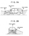
- Fig. 2A and Fig. 2B show areas to be filmed by cameras of the vehicle periphery monitor in accordance with the first embodiment.
- Fig. 3 schematically shows a situation in which a vehicle travels from one road into another road by making a left turn.
- Fig. 4 is a flowchart of a control routine that is executed to shift photo images displayed by an indicator display in the first embodiment.
- Fig. 5A and Fig. 5B show in a time-series manner photo images displayed by the indicator display when a side camera is required under the situation shown in Fig. 3 .
- Fig. 6 is a flowchart of a control routine that is executed to shift photo images displayed by the indicator display in a second embodiment of the invention.
- Fig. 7 is a flowchart of a control routine that is executed to shift photo images displayed by the indicator display in a third embodiment of the invention.
- Fig. 8 is a flowchart of a control routine that is executed to shift photo images displayed by the indicator display in a fourth embodiment of the invention.
- Fig. 1 shows a system configuration of a vehicle periphery monitor 20 in accordance with a first embodiment of the invention.
- a vehicle equipped with the vehicle periphery monitor 20 has front wheels as turnable wheels that are turned in accordance with a steering operation performed by the driver and rear wheels as non-turnable wheels.
- the vehicle periphery monitor 20 has a monitor-purpose electronic control computer (hereinafter referred to simply as "a computer") 22.
- the computer 22 controls the vehicle periphery monitor 20.
- a shift position sensor 24, a steering angle sensor 26, and a vehicle speed sensor 28 are connected to the computer 22.
- the shift position sensor 24 outputs a signal corresponding to a position of a gear-shift lever operated by the driver.
- the steering angle sensor 26 outputs a signal corresponding to a steering angle ⁇ of a steering wheel operated by the driver.
- the vehicle speed sensor 28 generates a pulse signal at intervals of a period corresponding to a vehicle speed SPD.
- the signals output from the shift position sensor 24, the steering angle sensor 26, and the vehicle speed sensor 28 are supplied to the computer 22.
- the computer 22 detects a position of the gear-shift lever on the basis of an output signal of the shift position sensor 24, detects a steering angle ⁇ on the basis of an output signal of the steering sensor 26, and detects a vehicle speed SPD on the basis of an output signal of the vehicle speed sensor 28. It is assumed herein that the steering angle ⁇ is positive when the steering wheel has been turned to the left (i.e., counterclockwise) and that the steering angle ⁇ is negative when the steering wheel has been turned to the right (i.e., clockwise).
- the computer 22 determines on the basis of a position of the gear-shift lever whether or not the wheels are coupled with power (i.e., whether or not the vehicle is in a driven state) or whether or not the wheels are uncoupled with power (i.e., whether or not the vehicle is in a non-driven state). If the vehicle is in a coupled state, the computer 22 further determines whether or not the vehicle is moving forwards or whether or not the vehicle is moving backwards. The computer 22 estimates a turning radius occurring in the vehicle on the basis of the steering angle ⁇ and the vehicle speed SPD, detects a position of the pertinent vehicle with respect to a reference position, and detects an amount of change in the direction of the vehicle (i.e., deflection angle ⁇ ).
- the computer 22 calculates a predicted travel path (guidance route) which is estimated to be covered when the vehicle moves forwards or backwards, on the basis of a turning radius estimated on the basis of the steering angle ⁇ .
- a back camera 30 disposed at a center of a door of a vehicle rear portion, a front camera 32 disposed at a center of a grille of a vehicle front portion, and a side camera 34 disposed in a lateral portion on the other side of the driver seat of the vehicle (e.g., in a door mirror stay) are connected to the computer 22. It is also appropriate that the back camera 30 and the front camera 32 be disposed on a bumper or the like in the vehicle rear portion or the vehicle front portion. Further, it is also appropriate that the side camera 34 be disposed in a lateral portion other than the door mirror stay.
- Fig. 2A and Fig. 2B show areas filmed by the cameras 30 to 34 in the first embodiment. It is to be noted herein that the areas filmed by the cameras 30 to 34 are indicated by diagonal lines in Fig. 2A and Fig. 2B .
- the back camera 30 has an optical axis oriented backwards from the vehicle rear portion, and films a predetermined area stretching backwards therefrom, including a dead area invisible from the driver.
- the front camera 32 has an optical axis oriented forwards from the vehicle front portion, and films a predetermined area stretching forwards therefrom, including a dead area invisible from the driver.
- the side camera 34 has an optical axis oriented sidewards and diagonally forwards from a vehicle lateral portion, and films a predetermined area stretching in that direction, including a dead area invisible from the driver.
- the images filmed by the cameras 30 to 34 (hereinafter referred to as a rear photo image, a front photo image, and a lateral photo image respectively) are supplied to the computer 22.
- an indicator display 40 is connected to the computer 22.
- the indicator display 40 is disposed in a console or the like in a compartment so as to ensure visibility of the driver.
- the computer 22 selects one of a rear photo image filmed by the back camera 30, a front photo image filmed by the front camera 32, and a lateral photo image filmed by the side camera 34 in accordance with a regulation to be described later, and drives the indicator display 40 so that the selected image is displayed by the indicator display 40.
- a back camera request switch 50, a front camera request switch 52, and a side camera request switch 54 are also connected to the computer 22.
- the request switches 50 to 54 are disposed in the console or the like in the compartment so as to be operable by the driver.
- the request switches 50 to 54 be designed to appear in a touch-panel manner on a screen of the indicator display 40.
- the back camera request switch 50 is a switch that outputs a signal corresponding to whether or not the driver requests a rear photo image filmed by the back camera 30 to be displayed by the indicator display 40.
- the front camera request switch 52 is a switch that outputs a signal corresponding to whether or not the driver requests a front photo image filmed by the front camera 32 to be displayed by the indicator display 40.
- the side camera request switch 54 is a switch that outputs a signal corresponding to whether or not the driver requests a lateral photo image filmed-by the side camera 34 to be displayed by the indicator display 40.
- the output signals of the request switches 50 to 54 are supplied to the computer 22.
- the computer 22 specifies an image requested by the driver to be displayed by the indicator display 40, on the basis of the output signals of the request switches 50 to 54.
- a timer 58 is built into the computer 22.
- the timer 58 counts a time starting from a timing when a photo image on the indicator display 40 is first displayed through the request switches 50 to 54 or through fulfillment of a predetermined condition by a vehicle state as will be described later (also including a time after a shift from an image filmed by one camera to an image filmed by another camera).
- the computer 22 performs predetermined processings on the basis of a value counted by the timer 58, as will be described later.
- the computer 22 causes the indicator display 40 to display a photo image requested by the driver and specified on the basis of the output signals of the back camera request switch 50, the front camera request switch 52, and the side camera request switch 54.
- the indicator display 40 displays a photo image requested by the driver and specified on the basis of the output signals of the back camera request switch 50, the front camera request switch 52, and the side camera request switch 54.
- the vehicle of the first embodiment has the front wheels as turnable wheels and the rear wheels as non-turnable wheels. Hence, whether the vehicle is making a turn while moving forwards or backwards, the turn-wise inner rear wheel moves along the innermost path (with a minimum radius) and the turn-wise outer front wheel moves along the outermost path (with a maximum radius).
- an inner-wheel predicted travel locus a locus estimated to be actually traced by the turn-wise inner rear wheel moving with the minimum radius
- an outer-wheel predicted travel locus a locus estimated to be actually traced by the turn-wise outer front wheel moving with the maximum radius
- the computer 22 calculates an inner-wheel predicted travel locus X and an outer-wheel predicted travel locus Y on the basis of a turning radius, conforms the inner-wheel predicted travel locus X and the outer-wheel predicted travel locus Y with photo images filmed by the cameras 30 to 34, and displays in a superimposed manner those travel loci X, Y by means of the indicator display 40 where the photo images are displayed. It is also appropriate herein that the computer 22 cause the indicator display 40 to display in a superimposed manner an elongation representative of vehicle width (hereinafter referred to as vehicle width elongation) which is determined from a positional relationship among the cameras 30 to 34 and a body of the vehicle. In this case, the inner-wheel predicted travel locus X, the outer-wheel predicted travel locus Y, and the vehicle width elongation Z are displayed by the indicator display 40 in mutually different shapes, colors, or the like.
- vehicle width elongation an elongation representative of vehicle width
- display of a lateral photo image filmed by the side camera 34 on the indicator display 40 is requested by operating the side camera request switch 54 mainly in the following cases where: (a) the driver confirms a situation in the periphery laterally leftward of the vehicle, for example, at the time of takeoff; (b) the driver confirms a distance to be covered when pulling the vehicle over toward a left wall; and (c) the driver confirms whether there is any risk that the side of a vehicle hits when making a left turn.
- Fig. 3 schematically shows a situation in which a vehicle travels from a road 82 into a narrow road 84 by making a left turn. It is assumed herein that a lateral wall 86 exists beside the road 82, that lateral walls 88, 89 exist beside the road 84, and that the lateral walls 86, 88 form a corner 92. Fig. 3 also shows locations (1), (2), and (3) that are sequentially passed by the vehicle 80 when making a left turn and entering the road 84.
- the driver is required to first confirm the possibility that the side of a vehicle hits due to a difference between the turn-wise inner front and rear wheels and a gap between a lateral-left portion of the vehicle 80 and the corner 92 (indicated by O in Fig. 3 ), and then to confirm, after duration of the turning, a gap between a front-right position of the vehicle 80 and a lateral wall 90 (indicated by O in Fig. 3 ).
- a lateral photo image that has been displayed by the indicator display 40 through operation of the side camera request switch 54 remain as it is for a long time.
- the vehicle periphery monitor 20 of the first embodiment is characterized in shifting the photo image displayed by the indicator display 40 from a lateral photo image filmed by the side camera 34 to a front photo image filmed by the front camera 32 at a suitable timing so as to confirm a gap between the front-right portion of the vehicle 80 and an obstacle such as the lateral wall 90, without requiring the driver to perform any operation.
- This characteristic part will be described hereinafter.
- the driver In the situation shown in Fig. 3 , the driver must determine whether there is the possibility that the side of a vehicle hits on the turn-wise inner side when the vehicle 80 is located substantially parallel to the road 82 immediately before making a left turn into the road 84 (the state indicated by (1) in Fig. 3 ). The driver must also confirm there is a gap between the lateral-left portion of the vehicle and the corner 92 when the vehicle 80 has actually traveled from the road 82 into the road 84 (the state indicated by (2) in Fig. 3 ). Furthermore, the driver must confirm a gap between the front-right portion of the vehicle 80 and the lateral wall 90 when the vehicle 80 has continued to turn for a certain period (the state indicated by (3) in Fig. 3 ).
- the indicator display 40 starts displaying a lateral photo image filmed by the side camera 34 through operation of the side camera request switch 54 performed by the driver so as to determine whether the side of a vehicle hits in the aforementioned case (c)
- the lateral photo image remains displayed until the vehicle 80 turns to almost pass the corner 92. If the vehicle reaches such a turning state, a shift to a front photo image filmed by the front camera 32 is made.
- the amount of change in direction of the vehicle 80 is substantially constant from the start of the confirmation until the vehicle 80 passes the corner 92.
- the photo image displayed by the indicator display 40 is shifted depending on whether or not the deflection angle ⁇ of the vehicle 80 has reached a predetermined angle, for example, the photo image displayed by the indicator display 40 is prevented from being shifted when the driver confirms a peripheral situation of the area beside the vehicle, at the time of takeoff or when the driver confirms a process of pulling the vehicle over.
- Fig. 4 is an exemplary flowchart of a control routine that is executed by the computer 22 in the first embodiment so as to realize the aforementioned functions.
- the routine shown in Fig. 4 is repeatedly started every time processings thereof are terminated. If the routine shown in Fig. 4 is started, the processing in step 100 is first performed.
- step 100 it is determined whether or not the front camera request switch 52 has been turned on, that is, whether or not the display of a front photo image filmed by the front camera 32 by means of the indicator display 40 has been requested. If the result of the determination is positive, the processing in step 102 is then performed. On the other hand, if the result of the determination is negative, the processing in step 104 is then performed.
- step 102 the processing of causing the indicator display 40 to display a front photo image filmed by the front camera 32 as to an area in front of the vehicle is performed. If the processing in step 102 is performed, the indicator display 40 thereafter displays a sight in front of the vehicle 80. If the processing in step 102 is terminated, the present routine is terminated.
- step 104 it is determined whether or not the side camera request switch 54 has been turned on, that is, whether or not the display of a lateral photo image filmed by the side camera 34 by means of the indicator display 40 has been requested. If the result of the determination is negative, the present routine is terminated without performing any further processing afterwards. On the other hand, if the result of the determination is positive, the processing in step 106 is then performed.
- step 106 it is determined whether or not the deflection angle ⁇ of the vehicle 80, which has been detected on the basis of the steering angle ⁇ detected by the steering angle sensor 26 and the vehicle speed SPD detected by the vehicle speed sensor 28, is smaller than a predetermined angle ⁇ 1, on the assumption that the vehicle 80 is oriented in a reference direction when the display of a lateral photo image is requested through operation of the side camera request switch 54.
- the predetermined angle ⁇ 1 is a deflection angle ⁇ of the vehicle 80 from a time when the side camera request switch 54 is operated to a time when the vehicle 80 is estimated to pass the corner 92.
- step 108 If a relationship ⁇ ⁇ ⁇ 1 has been established, it can be determined that the vehicle 80 has not turned to the extent of passing the corner 92 after operation of the side camera request switch 54. In this case, it is appropriate that a lateral photo image filmed by the side camera 34 be displayed as requested. Accordingly, if such a determination is made, the processing in step 108 is then performed.
- step 108 the processing of causing the indicator display 40 to display a lateral photo image filmed by the side camera 34 as to a lateral area of the vehicle is performed. If the processing of this step 108 is performed, the indicator display 40 thereafter displays a sight beside the vehicle 80. If the processing of this step 108 is terminated, the present routine is terminated.
- the relationship ⁇ ⁇ ⁇ 1 has not been established in the aforementioned step 106, that is, if a relationship ⁇ ⁇ ⁇ 1 has been established, it can be determined that the vehicle 80 has passed the corner 92, and there is no need to thereafter cause the indicator display 40 to display a lateral photo image filmed by the side camera 34. In this case, it is appropriate that the photo image displayed by the indicator display 40 be thereafter shifted from the lateral photo image filmed by the side camera 34 to a front photo image filmed by the front camera 32.
- the processing of causing the indicator display 40 to display the front photo image filmed by the front camera 32 as to the area in front of the vehicle is performed in the aforementioned step 102.
- the lateral photo image filmed by the side camera 34 can be displayed as requested until the deflection angle of the vehicle 80 reaches the predetermined angle ⁇ 1 after the request has been made, and the front photo image filmed by the front camera 32 can be displayed instead of the lateral photo image after the deflection angle ⁇ has reached the predetermined angle ⁇ 1.
- Fig. 5A and Fig. 5B show in a time-series manner photo images to be displayed by the indicator display 40 in the case where the side camera request switch 54 has been operated under the situation shown in Fig. 3 in the first embodiment.
- the photo images are displayed by the indicator display 40 as shown in Fig. 5A and Fig. 5B , it is possible to cause the driver at an early stage of a left turn of the vehicle to confirm the possibility that the side of a vehicle hits due to a difference between the turn-wise inner wheels and to confirm a gap between the lateral portion of the vehicle 80 and the corner 92. Further, it is also possible to cause the driver at a late stage of the left turn of the vehicle to confirm a gap between the front portion of the vehicle 80 and the lateral wall 90.
- a shift of the photo image displayed by the indicator display 40 from the lateral photo image to the front photo image under the situation in which the display of the lateral photo image filmed by the side camera 34 has been requested is not made on the basis of an operation performed by the driver.
- This shift is made through a determination made on the monitor side on the basis of the deflection angle ⁇ of the vehicle 80.
- the driver is prevented from facing an increase in operational burden in making such a shift of display.
- the driver can instinctively recognize a situation surrounding the vehicle, and the driver is prevented from losing visibility.
- the lateral photo image filmed by the side camera 34 is displayed as requested until the deflection angle of the vehicle 80 reaches the predetermined angle ⁇ 1 after the request has been made, and a front photo image filmed by the front camera 32 is displayed instead of the lateral photo image after the deflection angle ⁇ has reached the predetermined angle ⁇ 1.
- a timing for a shift between the lateral photo image and the front photo image can be suitably set as a timing when the vehicle is highly likely to come into contact with an obstacle or the like.
- the vehicle periphery monitor it is possible to adequately inform the driver of a peripheral situation of a portion of the vehicle 80 which tends to contact something, namely, of a peripheral situation of the vehicle which is wanted by the driver and to which attention has to be paid when the vehicle 80 makes a left turn, without causing an increase in operational burden or a reduction in visibility to the driver.
- the driver can be reminded to pay attention so as to ensure safe driving when making a left turn, and it is possible for the driver to suitably and easily operate the vehicle.
- the deflection angle ⁇ of the vehicle 80 does not substantially change from a time when the display of the lateral photo image by means of the indicator display 40 is started to a time when confirmation of the peripheral situation is completed or when the process of pulling the vehicle over is completed.
- the deflection angle ⁇ has not reached the predetermined angle ⁇ 1, the lateral photo image remains displayed.
- the photo image displayed by the indicator display 40 is prevented from being unexpectedly shifted to the photo image filmed by the front camera 32.
- the indicator display 40 if photo images filmed by the cameras 30 to 34 are displayed by the indicator display 40, the inner-wheel predicted travel locus X, the outer-wheel predicted travel locus Y, and the vehicle width elongation of the vehicle 80 are displayed in a superimposed manner by the indicator display 40 in accordance with the photo images as described above.
- the inner-wheel predicted travel locus X and the vehicle width elongation Z of the vehicle 80 are displayed in a superimposed manner. It is also appropriate herein that an area between the inner-wheel predicted travel locus X and the vehicle width elongation Z be colored on the indicator display 40 as shown in Fig. 5A . According to this construction, if the driver has requested a lateral photo image filmed by the side camera 34 to be displayed when the vehicle 80 makes a right or left turn, it is possible for the driver to suitably grasp a mutual positional relationship between the vehicle 80 and the corner 92.
- the precision in confirming the possibility that the side of a vehicle hits on the turn-wise inner side and the precision in confirming a gap between the vehicle 80 and the corner 92 can be enhanced.
- the vehicle can be guaranteed of safe driving when making a right or left turn.
- the outer-wheel predicted travel locus Y is displayed in a superimposed manner.
- This construction makes it possible for the driver to adequately grasp a mutual positional relationship between the vehicle 80 and the lateral wall 90 in the case where the driver has requested the lateral photo image filmed by the side camera 34 to be displayed when the vehicle 80 makes a right or left turn.
- the precision in confirming a gap between the vehicle and the lateral wall on the turn-wise outer side can be enhanced, and the vehicle can be guaranteed of safe driving when making a right or left turn.
- the inner-wheel predicted travel locus X and the outer-wheel predicted travel locus Y correspond to "the predicted travel locus” mentioned in the claims
- the front camera 32 corresponds to "the first camera” mentioned in the claims
- the side camera 34 corresponds to "the second camera” mentioned in the claims.
- the computer 22 performs the processings in step 102, step 106, and step 108 in the routine shown in Fig. 4 corresponds to "the controller” mentioned in the claims.
- the lateral photo image corresponds to "the first photo image” mentioned in the claims.
- the front photo image and the rear photo image correspond to "the second photo image” mentioned in the claims, which is obtained by filming an area other than the lateral photo image.
- the deflection angle ⁇ of the vehicle is detected on the basis of the steering angle ⁇ of the steering wheel and the vehicle speed SPD, and the photo image displayed by the indicator display 40 is shifted from the lateral photo image to the front photo image using the deflection angle ⁇ as a parameter.
- the invention is not limited to this construction. That is, it is also appropriate that a yaw angle generated by the vehicle be directly detected or that a deflection angle ⁇ be detected by integrating an output from a yaw rate sensor 29.
- the deflection angle ⁇ of the vehicle is detected on the basis of the steering angle ⁇ of the steering wheel detected by the steering angle sensor 26 and the vehicle speed SPD detected by the vehicle speed sensor 28, and it is determined whether or not the deflection angle ⁇ has reached the predetermined angle ⁇ 1 on the assumption that the vehicle is oriented in a reference direction when the display of a lateral photo image is started through operation of the side camera request switch 54, so as to shift the photo image displayed by the indicator display 40. It is also appropriate to additionally determine on the basis of a relationship between the steering angle ⁇ and running distance whether or not the deflection angle ⁇ has reached the predetermined angle ⁇ 1.
- the vehicle covers a certain distance while maintaining a steering angle equal to or larger than a certain value, the vehicle is deflected by a certain angle or more with respect to an initial reference state. Hence, it is appropriate to determine that the deflection angle ⁇ has reached the predetermined angle ⁇ 1 if the vehicle has continuously covered a predetermined distance with the steering angle ⁇ thereof being equal to or larger than a predetermined angle. It is also possible to calculate a running distance on the basis of an output from the vehicle speed sensor.
- the photo images filmed by the cameras 30 to 34 are displayed by the indicator display 40, in principle, through the operation of the request switches 50 to 54 performed by the driver.
- the second embodiment while the vehicle is running, photo images filmed by the cameras 30 to 34 are selectively displayed by the indicator display 40 in accordance with a running state of the vehicle, without requiring the driver to perform any operation.
- components identical to those of the aforementioned construction shown in Fig. 1 are denoted by the same reference numerals and will not be described again below.
- the turning radius of the vehicle is small.
- the lateral photo image filmed by the side camera 34 often covers a larger area in the traveling direction of the vehicle than the front photo image filmed by the front camera 32. If the turning radius is small, the angular difference between the turn-wise inner wheels is enlarged accordingly. In consideration of this respect, when the vehicle makes a sharp left turn while moving forwards, the peripheral situation to which the driver has to pay attention is a situation on the left of the vehicle.
- the driver can be informed of a situation to which the driver has to pay attention in the traveling direction of the vehicle. Further, if the turning of the vehicle is completed under the situation in which the lateral photo image filmed by the side camera 34 is displayed by the indicator display 40 according to the aforementioned method, the steering angle ⁇ decreases. Hence, the peripheral situation of the vehicle to which the driver has to pay attention thereafter shifts from the situation on the left of the vehicle to a situation in front of the vehicle.
- the driver can be informed of a situation to which the driver has to pay attention in the traveling direction of the vehicle.
- Fig. 6 shows an exemplary flowchart of a control routine that is executed by the computer 22 in the second embodiment so as to realize the aforementioned functions.
- the routine shown in Fig. 6 is repeatedly started every time processings thereof are terminated. If the routine shown in Fig. 6 is started, the processing in step 150 is first performed.
- step 150 it is determined whether or not the vehicle speed SPD detected by means of the vehicle speed sensor 28 is "0", that is, whether or not the vehicle is in a stopped state. If the vehicle is in a stopped state as a result, it is impossible to cause the indicator display 40 to display a photo image in accordance with a traveling direction of the vehicle. Thus, if the result of this determination is positive, the processing in step 152 is then performed. On the other hand, if it is determined that the vehicle is not in a stopped state, the processing in step 154 is then performed.
- step 152 the processing of causing the indicator display 40 to display photo images of the cameras 30 to 34 in accordance with operational states of the back camera request switch 50, the front camera request switch 52, and the side camera request switch 54 is performed. If the processing in step 152 is performed, the indicator display 40 thereafter displays a sight corresponding to a request. If the processing in step 152 is terminated, the present routine is terminated.
- step 154 it is determined whether or not the gear-shift lever detected by means of the shift position sensor 24 is at a reverse position "R". If the gear-shift lever is at the reverse position "R", it can be determined that the vehicle is in a state of moving backwards. The area behind the vehicle is often invisible from the driver. Hence, in this case, it is appropriate that the rear photo image filmed by the back camera 30 be displayed by the indicator display 40 regardless of the steering angle ⁇ of the steering wheel. Thus, if the result of this determination is positive, the processing in step 156 is then performed. On the other hand, if the gear-shift position is not at the reverse position "R", the aforementioned inconvenience is not caused. Thus, if the result of this determination is negative, the processing in step 158 is then performed.
- step 156 the processing of causing the indicator display 40 to display the rear photo image filmed by the back camera 30 as to the area behind the vehicle is performed. If the processing in step 156 is performed, the indicator display 40 thereafter displays a sight behind the vehicle. If the processing in step 156 is terminated, the present routine is terminated.
- step 158 it is determined whether or not the steering angle ⁇ of the steering wheel detected by means of the steering angle sensor 26 is smaller than a predetermined angle ⁇ 1.
- the predetermined angle ⁇ 1 is a steering angle ⁇ at a time immediately preceding a time when it can be determined that the lateral photo image filmed by the side camera 34 covers a larger area in the traveling direction of the vehicle than the front photo image filmed by the front camera 32. If it is determined that a relationship ⁇ ⁇ ⁇ 1 has been established as a result, the processing in step 160 is then performed. On the other hand, if it is determined that the relationship ⁇ ⁇ ⁇ 1 has not been established, the processing in step 162 is then performed.
- step 160 the processing of causing the indicator display 40 to display the front photo image filmed by the front camera 32 as to the area in front of the vehicle is performed. If the processing in step 160 is performed, the indicator display 40 thereafter displays a sight in front of the vehicle. If the processing in step 160 is terminated, the present routine is terminated. Further, in step 162, the processing of causing the indicator display 40 to display the lateral photo image filmed by the side camera 34 as to the area beside the vehicle is performed. If the processing in step 162 is performed, the indicator display 40 thereafter displays a sight beside the vehicle. If the processing in step 162 is terminated, the processing in step 164 is then performed.
- step 164 it is determined whether or not the steering angle ⁇ has become equal to or larger than a predetermined angle ⁇ 2 that is larger than the predetermined angle ⁇ 1 after being regarded in the aforementioned step 158 as having reached the predetermined angle ⁇ 1 and has thereafter dropped below the predetermined angle ⁇ 2.
- the predetermined angle ⁇ 2 is a steering angle ⁇ from which it can be determined that the lateral photo image filmed by the side camera 34 covers a larger area in the traveling direction of the vehicle than the front photo image filmed by the front camera 32.
- the predetermined angle ⁇ 2 is larger than the aforementioned predetermined angle ⁇ 1.
- step 160 the processing in step 160 is then performed, and the processing of shifting the photo image displayed by the indicator display 40 from the lateral photo image filmed by the side camera 34 to the front photo image filmed by the front camera 32 is performed.
- the processing in step 166 is then performed.
- step 166 it is determined whether or not a time T that has elapsed after the start of the display of the lateral photo image filmed by the side camera 34 in the aforementioned step 162 has reached a predetermined time T0.
- the predetermined time T0 is set as an average time from a time when the steering angle ⁇ of the vehicle becomes equal to or larger than the predetermined angle ⁇ 1 through a time when the steering angle ⁇ then becomes equal to or larger than the predetermined angle ⁇ 2 to a time when the steering angle ⁇ drops below the predetermined angle ⁇ 2. If it is determined that a relationship T ⁇ T0 has not been established as a result, the processing in the aforementioned step 164 is repeatedly performed.
- the indicator display 40 makes it possible to cause the indicator display 40 to display the photo images corresponding to the request switches 50 to 54 while the vehicle is stopped, to cause the indicator display 40 to display the rear photo image filmed by the back camera 30 disposed at the rear portion of the vehicle body when the vehicle moves backwards, to cause the indicator display 40 to display the front photo image filmed by the front camera 32 if the steering angle of the steering wheel is small under the situation in which the vehicle moves forwards, and to cause the indicator display 40 to display the lateral photo image filmed by the side camera 34 if the steering angle of the steering wheel is large under the situation in which the vehicle moves forwards.
- the driver while the vehicle is traveling, the driver can be informed of a situation in front of the vehicle where the traveling direction of the vehicle can be easily recognized if the steering angle ⁇ is small, whereas the driver can be informed of a situation beside the vehicle where the traveling direction of the vehicle can be easily recognized if the steering angle ⁇ is large.
- a so-called hysteresis is set as to a threshold of a parameter for shifting the photo image displayed by the indicator display 40. That is, the condition for starting the display of a lateral photo image filmed by the side camera 34 is that the steering angle ⁇ reaches the predetermined angle ⁇ 1 which is relatively small, whereas the condition for thereafter starting the display of a front photo image filmed by the front camera 32 is that the steering angle ⁇ drops below the predetermined angle ⁇ 2 which is relatively large.
- the vehicle periphery monitor 20 in accordance with the second embodiment informs the driver well in advance of a peripheral situation of the vehicle to which the driver has to pay attention, and thus makes it possible to keep the driver alert and to ensure safe driving during a turn.
- a hysteresis is set as to a threshold of a parameter for shifting the photo image displayed by the indicator display 40, even if the turning of the vehicle has been completed, for example, because the steering angle ⁇ that has reached the predetermined angle ⁇ 1 does not reach the predetermined angle ⁇ 2 afterwards, the lateral photo image filmed by the side camera 34 may remain displayed.
- the lateral photo image filmed by the side camera 34 may remain displayed.
- the predetermined angle ⁇ 1 corresponds to "the first angle” mentioned in the claims
- the predetermined angle ⁇ 2 corresponds to “the second angle” mentioned in the claims
- the predetermined time T0 corresponds to "the predetermined time” mentioned in the claims.
- the lateral photo image remains displayed until the steering angle ⁇ is reduced or until a predetermined time elapses.
- the photo image displayed by the indicator display 40 be temporarily shifted to the front photo image filmed by the front camera 32, for example, every time a certain period elapses or every time the vehicle covers a certain distance.
- the third embodiment is designed to help the driver check safety by causing the indicator display 40 to display a peripheral situation of the vehicle as a photo image in the case where the vehicle is ready for takeoff, without requiring the driver to perform any operation.
- components identical to those of the aforementioned construction shown in Fig. 1 are denoted by the same reference numerals and will not be described again below.
- the vehicle has rear wheels RL, RR as non-turnable wheels and front wheels FL, FR as turnable wheels as described above.
- the front portion of the vehicle on the turn-wise outer side swings outwards considerably and thus causes a substantial difference between the tracks of the turn-wise outer wheels.
- the indicator display 40 it is appropriate from the standpoint of checking safety that the driver be informed of a situation beside the vehicle by causing the indicator display 40 to display a lateral photo image filmed by the side camera 34.
- Fig. 7 shows an exemplary flowchart of a control routine that is executed by the computer 22 in the third embodiment so as to realize the aforementioned functions.
- the routine shown in Fig. 7 is repeatedly started every time processings thereof are terminated. If the routine shown in Fig. 7 is started, the processing in step 200 is first performed.
- step 200 it is determined on the basis of an output signal of the shift position sensor 24 whether or not the gear-shift lever has been shifted from a neutral position "N", a parking position "P", or the reverse position "R” to a forward position "D". If this condition has been fulfilled, it can be determined that the vehicle is allowed to move forwards. Thus, the necessity to inform the driver of a situation behind the vehicle is not vital. Accordingly, if the determination is thus made, the processing in step 202 is then performed.
- step 202 it is determined whether or not the steering angle ⁇ of the steering wheel detected by means of the steering angle sensor 26 is smaller than a predetermined angle ⁇ 3.
- the predetermined angle ⁇ 3 is a steering angle ⁇ from which it can be determined that the lateral photo image filmed by the side camera 34 covers a larger area in the traveling direction of the vehicle than the front photo image filmed by the front camera 32. If a relationship ⁇ ⁇ ⁇ 3 has been established as a result, it is possible to determine that the vehicle starts moving forwards almost rectilinearly. Accordingly, if the determination is thus made, the processing in step 204 is then performed.
- step 204 the processing of causing the indicator display 40 to display the front photo image filmed by the front camera 32 as to the area in front of the vehicle is performed. If the processing in step 204 is performed, the indicator display 40 thereafter displays a sight in front of the vehicle. If the processing in step 204 is terminated, the processing in step 206 is performed.
- step 206 it is determined whether or not a time T F that has elapsed after the start of the display of the front photo image filmed by the front camera 32 in the aforementioned step 204 has reached a predetermined time T F0 .
- the predetermined time T F0 is set as a time that enables the driver to broadly grasp an overall situation in front of the vehicle. If the vehicle periphery monitor is equipped with a speaker in this case, it is also appropriate that the driver be informed through audio guidance of the fact that a photo image filmed by the camera has been displayed by the indicator display 40.
- the processing in step 206 is repeatedly performed until it is determined that a relationship T F ⁇ T F0 has been established.
- step 208 If it is determined as a result that the relationship T F ⁇ T F0 has been established, the processing in step 208 is then performed, and the photo image displayed by the indicator display 40 ceases to be displayed. If the processing in step 208 is terminated, the present routine is terminated.
- step 202 if a relationship ⁇ ⁇ ⁇ 3 has not been established, that is, if a relationship ⁇ ⁇ ⁇ 3 has been established (i.e., if the steering wheel has been considerably turned counterclockwise), it can be determined that the vehicle starts moving forwards while making a sharp left turn. In this case, it is appropriate to display a photo image filmed by the side camera 34 where the traveling direction of the vehicle can be easily recognized. Accordingly, if the determination is thus made, the processing in step 210 is then performed.
- step 210 the processing of causing the indicator display 40 to display the lateral photo image filmed by the side camera 34 as to the area beside the vehicle is performed. If the processing in step 210 is performed, a sight beside the vehicle is represented on the indicator display 40. If the processing in step 210 is terminated, the processing in step 212 is performed.
- step 212 it is determined whether or not a time T s that has elapsed after the start of the display of the lateral photo image filmed by the side camera 34 in the aforementioned step 210 has reached a predetermined time T s0 .
- the predetermined time T s0 is set as a time that enables the driver to broadly grasp an overall situation beside the vehicle.
- the processing in step 212 is repeatedly performed until it is determined that a relationship T s ⁇ T s0 has been established. If it is determined as a result that the relationship T s ⁇ T s0 has been established, the aforementioned processing in step 208 is then performed, and the photo image displayed by the indicator display 40 ceases to be displayed.
- step 214 is then performed.
- step 214 it is determined on the basis of an output signal of the shift position sensor 24 whether or not the gear-shift lever has been shifted from the neutral position "N", the parking position "P", or the forward position "D” to the reverse position "R". If this condition has been fulfilled, it can be determined that the vehicle is allowed to move backwards. Therefore, the necessity to inform the driver of a situation in front of the vehicle is vital. Accordingly, if the determination is thus made, the processing in step 214 is then performed. On the other hand, if it is determined that this condition has not been fulfilled, the processing in the aforementioned step 200 is performed.
- step 216 it is determined whether or not a steering angle - ⁇ of the steering wheel detected by means of the steering angle sensor 26 is smaller than a predetermined angle - ⁇ 4.
- a predetermined angle - ⁇ 4 is a steering angle ⁇ from which it can be determined that a difference between the turn-wise outer wheels is caused to such an extent that the front portion of the vehicle on the turn-wise outer side can be estimated to swing outwards considerably.
- a relationship - ⁇ ⁇ - ⁇ 4 has not been established as a result, that is, if a relationship - ⁇ ⁇ - ⁇ 4 has been established (i.e., if the steering wheel has been considerably turned clockwise), it is possible to determine that the vehicle starts moving backwards while making a sharp right turn, and it is appropriate to display a photo image filmed by the side camera 34.
- the aforementioned processing in step 210 is performed, and the indicator display 40 thereafter displays a sight beside the vehicle.
- the relationship - ⁇ ⁇ - ⁇ 4 has been established, it is possible to determine that the vehicle moves backwards almost rectilinearly.
- the processing in step 218 is then performed.
- step 218 the processing of displaying the rear photo image filmed by the back camera 30 as to the area behind the vehicle is performed. If the processing in step 218 is performed, the indicator display 40 thereafter displays a sight behind the vehicle. If the processing in step 218 is terminated, the processing in step 220 is performed.
- step 220 it is determined on the basis of an output signal of the shift position sensor 24 whether or not the gear-shift lever has been shifted from the reverse position "R" to another position. If the gear-shift lever is maintained in the reverse position "R", there is an extensive area behind the vehicle which is invisible from the driver. Hence, it is appropriate that the rear photo image filmed by the back camera 30 remain displayed. On the other hand, if the gear-shift lever has been shifted from the reverse position "R” to another position, the necessity to display the rear photo image diminishes. Accordingly, the processing in step 220 is repeatedly performed until it is determined that the aforementioned condition has been fulfilled. If it is determined that the condition has been fulfilled, the aforementioned processing in step 208 is then performed, whereby the photo image displayed by the indicator display 40 ceases to be displayed.
- the front photo image filmed by the front camera 32 can be displayed by the indicator display 40 if the steering angle of the steering wheel is small, and the lateral photo image filmed by the side camera 34 can be displayed if the steering angle is large.
- the rear photo image filmed by the back camera 30 can be displayed by the indicator display 40 if the steering angle of the steering wheel is small, and the lateral photo image filmed by the side camera 34 can be displayed by the indicator display 40 if the steering angle is large.
- the driver can be informed of a situation in front of the vehicle where the traveling direction of the vehicle can be easily recognized if the steering angle ⁇ is small during forward takeoff, and of a situation beside the vehicle where the traveling direction of the vehicle can be easily recognized if the steering angle ⁇ is large during forward takeoff. Further, the driver can be informed of a situation behind the vehicle where the traveling direction of the vehicle can be easily recognized if the steering angle ⁇ is small during backward takeoff, and of a situation beside the vehicle where the periphery of a region corresponding to a great difference between the turn-wise outer wheels is projected if the steering angle ⁇ is large during backward takeoff.
- the driver can be adequately informed of a peripheral situation of the vehicle to which the driver has to pay attention during takeoff (a situation beside the vehicle as an invisible area in particular) in accordance with a running state of the vehicle.
- the vehicle periphery monitor 20 in accordance with the third embodiment makes it possible to keep the driver alert during takeoff and to cause the driver to check the safety of an area surrounding the vehicle during takeoff.
- the front photo image filmed by the front camera 32 and the lateral photo image filmed by the side camera 34 cease to be displayed if the predetermined period has elapsed since the start of the display thereof.
- the driver does not focus too much attention on the screen of the indicator display 40.
- safe driving of the vehicle based on the operation by the driver can be reliably ensured.
- the computer 22 performs the processings in step 200 or 214 and step 202 or 216 in the aforementioned routine shown in Fig. 7 , corresponding to "the controller" mentioned in the claims.
- the front photo image filmed by the front camera 32 and the lateral photo image filmed by the side camera 34 cease to be displayed if the predetermined period has elapsed since the start of the display thereof.
- those photo images cease to be displayed not only in the case where the predetermined time has elapsed but also in the case where the vehicle has covered a predetermined distance, where the vehicle speed SPD has reached a predetermined vehicle speed, or the like. It is not absolutely required that those photo images cease to be displayed.
- the photo image displayed by the indicator display 40 be shifted to the front photo image filmed by the front camera 32 in the case where a predetermined time has elapsed, where the vehicle has covered a predetermined distance, or the like.
- the photo image displayed by the indicator display 40 is changed in accordance with the steering angle ⁇ of the steering wheel during takeoff of the vehicle.
- photo images filmed by the cameras 30 to 34 are displayed by the indicator display 40 in a predetermined order during takeoff of the vehicle. According to this construction, without causing an increase in operational burden or a reduction in visibility to the driver, the driver is broadly informed of a peripheral situation of the vehicle. Thus, by urging the driver to pay attention to an invisible area, the confirmation of safety in the periphery of the vehicle during takeoff thereof can be ensured.
- components identical to those of the aforementioned construction shown in Fig. 1 are denoted by the same reference numerals and will not be described again below.
- Fig. 8 shows an exemplary flowchart of a control routine that is executed by the computer 22 in the fourth embodiment so as to realize the aforementioned functions.
- the routine shown in Fig. 8 is repeatedly started every time processings thereof are terminated. If the routine shown in Fig. 8 is started, the processing in step 250 is first performed.
- step 250 it is determined on the basis of an output signal of the shift position sensor 24 whether or not the gear-shift lever has been shifted from the neutral position "N", the parking position “P", or the reverse position “R” to the forward position “D”, or whether or not the gear-shift lever has been shifted from the neutral position "N", the parking position "P", or the forward position “D” to the reverse position “R”.
- the processing in step 250 is repeatedly performed until it is determined that the aforementioned condition has been fulfilled. If it is determined as a result that the aforementioned condition has been fulfilled, the processing in step 252 is performed.
- step 252 the processing of displaying a front photo image filmed by the front camera 32 as to an area in front of the vehicle on the indicator display 40 is performed. If the processing in step 252 is performed, the indicator display 40 thereafter displays a sight in front of the vehicle. If the processing in step 252 is terminated, the processing in step 254 is performed.
- step 254 it is determined whether or not the time T F that has elapsed after the start of the display of the front photo image filmed by the front camera 32 in the aforementioned step 252 has reached a predetermined time T F1 .
- the predetermined time T F1 is set as a time that enables the driver to broadly grasp an overall situation in front of the vehicle. If the vehicle periphery monitor is equipped with a speaker in this case, it is also appropriate that the driver be informed through audio guidance of the fact that a photo image filmed by the camera has been displayed by the indicator display 40.
- the processing in step 254 is repeatedly performed until it is determined that a relationship T F ⁇ T F1 has been established. If it is determined as a result that the relationship T F ⁇ T F1 has been established, the processing in step 256 is then performed.
- step 256 the processing of causing the indicator display 40 to display a lateral photo image filmed by the side camera 34 as to an area beside the vehicle is performed. If the processing in step 256 is performed, the indicator display 40 thereafter displays a sight beside the vehicle. If the processing in step 256 is terminated, the processing in step 258 is performed.
- step 258 it is determined whether or not a time T S1 that has elapsed after the start of the display of the lateral photo image filmed by the side camera 34 in the aforementioned step 256 has reached a predetermined time T S1 .
- the predetermined time T S1 is set as a time that enables the driver to broadly grasp an overall situation beside the vehicle.
- the processing in step 258 is repeatedly performed until it is determined that a relationship T S ⁇ T S1 has been established. If it is determined as a result that the relationship T S ⁇ T S1 has been established, the aforementioned processing in step 260 is then performed.
- step 260 the processing of causing the indicator display 40 to display a rear photo image filmed by the back camera 30 as to an area behind the vehicle is performed. If the processing in step 260 is performed, a sight behind the vehicle is thereafter represented on the indicator display 40. If the processing in step 260 is terminated, the processing in step 262 is performed.
- step 262 it is determined whether or not a time T B that has elapsed after the start of the display of the rear photo image filmed by the back camera 30 in the aforementioned step 260 has reached a predetermined time T B1 .
- the predetermined time T B1 is set as a time that enables the driver to broadly grasp an overall situation behind the vehicle.
- the processing in step 262 is repeatedly performed until it is determined that a relationship T B ⁇ T B1 has been established. If it is determined as a result that the relationship T B ⁇ T B1 has been established, the processing in step 264 is performed.
- step 264 the photo image displayed by the indicator display 40 ceases to be displayed. If the processing in step 264 is terminated, the present routine is terminated.
- the front photo image filmed by the front camera 32, the lateral photo image filmed by the side camera 34, and the rear photo image filmed by the back camera 30 can be temporarily displayed in this order by the indicator display under the situation in which the vehicle takes off.
- the driver can be broadly informed of a peripheral situation of the vehicle during takeoff, without causing an increase in operational burden or a reduction in visibility to the driver.
- the vehicle periphery monitor 20 in accordance with the fourth embodiment it is possible to cause the driver to adequately check safety in starting the vehicle.
- the driver does not focus too much attention on the screen of the indicator display 40.
- safe driving of the vehicle based on the operation by the driver can be reliably ensured.
- the front photo image filmed by the front camera 32 and the rear photo image filmed by the back camera 30 correspond to "the second photo image" mentioned in the claims.
- the photo image to be temporarily displayed by the indicator display 40 is shifted in the order of the front photo image filmed by the front camera 32, the lateral photo image filmed by the side camera 34, and the rear photo image filmed by the back camera 30.
- the photo image displayed by the indicator display 40 it is not absolutely required that the photo image displayed by the indicator display 40 be shifted in this order. That is, it is also appropriate that the photo image displayed by the indicator display 40 be shifted in another order. Further, it is not invariably required that the photo image displayed by the indicator display 40 be shifted in a predetermined order. The order in which those photo images are displayed may be changed in accordance with the shift position or the steering angle ⁇ .
- the invention is not limited to this construction. It is also appropriate to determine whether or not the vehicle has become ready to take off, depending on whether or not a braking operation is being performed in a stopped state of the vehicle. In this construction, if the vehicle has temporarily stopped through a braking operation after having traveled for a while, the vehicle is regarded as having become ready to take off, and the photo images filmed by the cameras 30 to 34 are displayed by the indicator display 40. Hence, it is possible to permit the driver to check safety during takeoff of the vehicle. In this case, it is also appropriate that the photo image be displayed by the indicator display 40 if a predetermined delay time has elapsed after temporary stoppage of the vehicle through a braking operation, which follows a running state of the vehicle.
- the rear photo image filmed by the back camera 30 is displayed by the indicator display 40 if the driver is informed of a situation behind the vehicle
- the lateral photo image filmed by the side camera 34 is displayed by the indicator display 40 if the driver is informed of a situation beside the vehicle
- the front photo image filmed by the front camera 32 is displayed by the indicator display 40 if the driver is informed of a situation in front of the vehicle.
- the invention is not limited to this construction.
- one camera capable of filming the entire area surrounding the vehicle be disposed in the vehicle and that the photo image to be displayed by the indicator display 40 be shifted from one area to another by orienting the camera in a direction of which the driver is to be informed.
- the vehicle periphery monitor 20 is used to help the driver drive the vehicle having the rear wheels RL, RR as non-turnable wheels and the front wheels FL, FR as turnable wheels.
- the vehicle periphery monitor 20 can also be used to help the driver drive a vehicle having front wheels FL, FR as non-turnable wheels and rear wheels RL, RR as turnable wheels or a vehicle having front and rear wheels as turnable wheels.
- the side camera 34 is disposed only in the lateral portion on the other side of the driver seat, and the photo image filmed by the side camera 34 can be displayed by the indicator display 40.
- the driver can be informed of a situation beside the vehicle on the other side of the driver seat.
- the area beside the vehicle on the other side of the driver seat is less visible from the driver than the area beside the vehicle on the side of the driver seat. It is not absolutely required that the side camera 34 be disposed in the lateral portion on the other side of the driver seat.
- the side camera 34 be disposed in the lateral portion on the side of the driver seat and that the indicator display 40 be capable of displaying photo images filmed by the side camera 34.
- the driver can be adequately informed of a peripheral situation of a portion of the vehicle 80 which tends to come into contact with something, namely, of a peripheral situation of the vehicle which is wanted by the driver and to which attention has to be paid, if the driver has requested a lateral photo image filmed by the side camera to be displayed for the purpose of checking safety during a right turn or if the driver has considerably turned the steering wheel to the right. As a result, it is possible to keep the driver alert in driving safely during a right turn.
- the lateral photo image may include a photo image representing a continuous area extending from the lateral portion to the front portion of the vehicle in addition to a photo image representing the lateral portion of the vehicle.
- the steering angle that is actually relevant to the steering wheel is regarded as the steering angle of the vehicle.
- a steering that is actually relevant to the wheels be regarded as the steering angle of the vehicle.
- a front camera (32) for filming an area stretching forwards is disposed in a front portion of a vehicle.
- a side camera (34) for filming an area stretching laterally and diagonally forwards is disposed in a lateral-left portion of the vehicle.
- An indicator display (40) that can be visually recognized by a driver is disposed in a compartment of the vehicle. An amount of change in the direction of the vehicle, that is, a deflection angle ( ⁇ ) of the vehicle is detected on the basis of a vehicle speed and a steering angle ( ⁇ ) of a steering wheel, which have been detected by means of various sensors. After the indicator display (40) has started displaying a lateral photo image filmed by the side camera (34), the photo image displayed by the indicator display (40) is shifted from the lateral photo image filmed by the side camera (34) to a front photo image filmed by the front camera (32) if the deflection angle has reached a predetermined angle.
- This application is a divisional application of European patent application no. 02025187.2 (the "patent application"), also published under no. EP-A-1350671 . The original subject matter of the parent application is repeated below in the present specification and forms part of the content of this divisional application as filed.
Abstract
Description
- The invention relates to a vehicle periphery monitor for monitoring the periphery of a vehicle.
- In general, as disclosed in Japanese Patent Laid-Open Application No.
2000-172996 - In the aforementioned vehicle periphery monitor, if the driver selects a "pull-over-to-the-left" switch for pulling the vehicle over to the left for example, the indicator display displays a photo image representing a front-left area or a rear-left area. If the driver shifts a shift lever to an "R" range under a situation in which the "pull-over-to-the-left" switch has been selected, the indicator display displays a photo image obtained by synthesizing a front-left photo image and a rear-left photo image. Thus, in the aforementioned vehicle periphery monitor, the indicator display displays a photo image representing an area required by the driver. Hence, the driver is allowed to confirm, for example, whether or not the vehicle has approached an obstacle, by having a glance at the indicator display. As a result, the driver can be guaranteed of safe driving.
- However, the photo image displayed by the indicator display of the aforementioned vehicle periphery monitor is selected through a switching operation performed by the driver. Hence, in an attempt to suitably check safety or the like by looking at the indicator display, the driver is confronted with an increase in operational burden. For example, when the vehicle enters a narrow road by making a right or left turn, it is probable that a photo image representing an area beside the vehicle be displayed by the indicator display at an initial stage of the turn so as to allow the driver to confirm whether or not there is any risk that the side of a vehicle hits, and that a photo image representing an area in front of a corner of the vehicle be displayed by the indicator display at a late stage of the turn so as to allow the driver to confirm whether or not the front portion of the vehicle has come into contact with something. In this case, the aforementioned vehicle periphery monitor requires the driver to perform a switching operation for shifting photo images while making the turn. Hence, the driver is confronted with an excessive increase in operational burden.
- It is also possible that photo images representing different areas that are to be mutually shifted (i.e., the photo image representing the area beside the vehicle and the photo image representing the area in front of the corner of the vehicle in the aforementioned example) be simultaneously displayed by the indicator display. According to this method, the photo images displayed by the indicator display are small in size, and the manner in which these photo images are displayed is complicated. Hence, the driver has difficulty in instinctively recognizing a situation surrounding the vehicle. As a result, the driver is confronted with a reduction in visibility and has trouble in driving the vehicle appropriately.
- It is an object of the invention to construct a vehicle periphery monitor capable of informing a driver of a situation surrounding a vehicle upon request without causing an increase in operational burden or a reduction in visibility to the driver.
- A vehicle periphery monitor in accordance with a first aspect of the invention comprises a controller for causing an indicator display that can be visually recognized by a driver to selectively display a first photo image representing an area beside a vehicle (hereinafter referred to as a lateral photo image) or a second photo image representing an area different from the first photo image. The controller automatically makes a shift from one of the first and second photo images to the other upon fulfillment of a predetermined condition and causes the indicator display to display the other photo image.
- In the vehicle periphery monitor in accordance with the first aspect of the invention, the second photo image may be a photo image representing an area in front of the vehicle. In the vehicle periphery monitor in accordance with the first aspect of the invention, the controller may shift the photo image displayed by the indicator display from the lateral photo image to the front photo image if it is determined that a deflection angle has reached a predetermined angle under a situation in which the indicator display displays the lateral photo image.
- In the vehicle periphery monitor in accordance with the first aspect of the invention, if the deflection angle of the vehicle has reached the predetermined angle under a situation in which the indicator display displays the lateral photo image, the photo image displayed by the indicator display is shifted from the lateral photo image to the front photo image. That is, after the display of the lateral photo image at the initial stage of a turn, the front photo image is displayed if the turn has continued for a certain period. According to this construction, while the driver drives the vehicle into a narrow road by making a right or left turn for example, it is possible to inform the driver of a situation beside the vehicle at the initial stage of the turn, for example, for the purpose of allowing the driver to confirm whether or not there is any risk that the side of a vehicle hits, and to inform the driver of a situation in front of the vehicle at the late stage of the turn for the purpose of allowing the driver to confirm a gap between a lateral wall on the narrow road and the vehicle. According to the first aspect of the invention, it is possible to inform the driver of a situation surrounding the vehicle upon request and to keep the driver alert when making a turn, without causing an increase in operational burden or a reduction in visibility to the driver.
- In the aforementioned first aspect, the controller may determine whether or not the deflection angle has reached the predetermined angle, on the assumption that the vehicle is in a reference state when the indicator display starts displaying the lateral photo image. This makes it possible to suitably set the timing for a shift between the lateral photo image and the front photo image as a timing when the vehicle is highly likely to come into contact with an obstacle or the like.
- In the aforementioned first aspect, the controller may determine whether or not the deflection angle has reached the predetermined angle, on the basis of a yaw angle generated by the vehicle.
- Furthermore, in the aforementioned first aspect of the invention, the controller may determine whether or not the deflection angle has reached the predetermined angle, on the basis of a relationship between a steering angle generated by the vehicle and a running distance. If the vehicle has covered a certain distance while maintaining a steering angle equal to or larger than a certain angle, the vehicle is deflected by a certain angle or more with respect to its initial state. Hence, in the aforementioned first aspect of the invention, the controller may determine that the deflection angle has reached the predetermined angle, if the vehicle has continuously covered a predetermined distance with the steering angle being equal to or larger than a predetermined angle.
- In the aforementioned first aspect of the invention, the controller may cause the indicator display to display in a superimposed manner a predicted travel locus that is estimated to be traced by the vehicle when the indicator display displays the front photo image upon a shift from the lateral photo image.
- In this case, the predicted travel locus may be an outer-wheel predicted travel locus that is estimated to be traced by outer wheels of the vehicle.
- Further, the indicator display may display in a superimposed manner a predicted travel locus that is estimated to be traced by the vehicle when the indicator display displays the lateral photo image. In this case, the predicted travel locus may be an inner-wheel predicted travel locus that is estimated to be traced by inner wheels of the vehicle. Thus, if the predicted travel locus that is estimated to be traced by the vehicle is displayed in a superimposed manner when the indicator display displays the front photo image or the lateral photo image, it is possible to allow the driver to grasp a positional relationship between the vehicle and an obstacle or the like by having a glance at the indicator display, without causing an increase in operational burden to the driver.
- In the aforementioned first aspect of the invention, the lateral photo image may be a photo image representing an area beside the vehicle on the other side of a driver seat. Thus, the driver can be informed of a situation beside the vehicle on the other side of the driver seat, despite the fact that the area beside the vehicle on the other side of the driver seat is less visible from the driver than the area beside the vehicle on the side of the driver seat.
- Further, in the aforementioned first aspect of the invention, it is also appropriate that a first camera disposed in a front portion of the vehicle and having an optical axis oriented toward an area in front of the vehicle be provided to film the area in front of the vehicle, that a second camera disposed in a lateral portion of the vehicle and having an optical axis oriented toward an area beside the vehicle be provided to film the area beside the vehicle, and that the controller cause the indicator display to selectively display the front photo image filmed by the first camera or the lateral photo image filmed by the second camera.
- A vehicle periphery monitor in accordance with a second aspect of the invention comprises a controller capable of causing an indicator display that can be visually recognized by a driver to display a first photo image (hereinafter referred to as a lateral photo image) representing an area beside the vehicle. The controller causes the indicator display to display the lateral photo image if a steering angle has reached a first angle. The controller stops the indicator display from displaying the lateral photo image if the steering angle has reached and then dropped below a second angle that is larger than the first angle.
- In the second aspect of the invention, the indicator display displays the lateral photo image if the steering angle of the vehicle has reached the first angle. Hence, the driver can be provided at an early timing in advance with a photo image of an area stretching in a direction along which the vehicle travels while making a turn, without causing an increase in operational burden or a reduction in visibility to the driver. If the steering angle of the vehicle has reached and then dropped below a second angle that is larger than the first angle, the indicator display stops displaying the lateral photo image. If the steering angle has temporarily increased and then decreased, it can be determined that the vehicle makes a shift from a state of turning to a state of traveling straight ahead. The demand to monitor the area beside the vehicle falls. Accordingly, the invention makes it possible to inform the driver of a situation beside the vehicle during a turn, at an early timing and for a required period.
- In this case, in the second aspect of the invention, the controller may also stop the indicator display from displaying the lateral photo image if the lateral photo image remains displayed by the indicator display for a predetermined period. Thus, it is possible to prevent the lateral photo image from being continuously displayed due to the steering angle that has not reached the second angle yet after having reached the first angle, without imposing an operational burden on the driver.
- In the second aspect of the invention, it is appropriate that the controller cause the indicator display to selectively display the lateral photo image or the front photo image representing the area different from the lateral photo image, namely, the area in front of the vehicle, and that the controller cause the indicator display to display the front photo image if the indicator display has stopped displaying the lateral photo image. Thus, while the driver can be provided at an early timing in advance with a photo image of an area stretching in a direction along which the vehicle travels during a turn, the driver can be provided at an early timing in advance with a photo image of an area stretching in a direction along which the vehicle travels straight ahead at a late stage of the turn, without causing an increase in operational burden or a reduction in visibility to the driver.
- A vehicle periphery monitor in accordance with a third aspect of the invention comprises a controller for causing an indicator display that can be visually recognized by a driver to selectively display a first photo image representing an area beside a vehicle (hereinafter referred to as a lateral photo image) or a front photo image representing an area different from the first photo image, namely, an area in front of the vehicle. The controller causes the indicator display to temporarily display the front photo image if a predetermined time has elapsed under a situation in which the indicator display displays the lateral photo image.
- In the aforementioned third aspect of the invention, the indicator display temporarily displays the front photo image if the predetermined time has elapsed under the situation in which the indicator display displays the lateral photo image. According to this construction, the driver can be temporarily informed of a situation in front of the vehicle while being informed of a situation beside the vehicle, without causing an increase in operational burden or a reduction in visibility to the driver. Thus, by keeping the driver alert for the area in front of the vehicle as well, the driver can be prevented from focusing too much attention on the area beside the vehicle.
- A vehicle periphery monitor in accordance with a fourth aspect of the invention comprises a controller capable of causing an indicator display that can be visually recognized by a driver to display a first photo image representing an area beside a vehicle (hereinafter referred to as a lateral photo image). The controller causes the indicator display to temporarily display the lateral photo image if it is determined that the vehicle has become ready to take off and that the steering angle is equal to or larger than the predetermined angle.
- In the vehicle periphery monitor as the fourth aspect of the invention, the indicator display temporarily displays the lateral photo image if the vehicle has become ready to take off with the steering angle being equal to or larger than the predetermined angle. According to this construction, the driver can be informed of a situation beside the vehicle as a dead area during takeoff with a large steering angle, without causing an increase in operational burden or a reduction in visibility to the driver. Thus, by keeping the driver alert for the dead area, the driver is allowed to check the security of the area surrounding the vehicle.
- A vehicle periphery monitor in accordance with a fifth aspect of the invention comprises a controller for causing an indicator display that can be visually recognized by a driver to selectively display a first photo image representing an area beside a vehicle (hereinafter referred to as a lateral photo image) or a traveling-direction photo image representing an area different from the lateral photo image, namely, an area in front of or behind the vehicle. The controller causes the indicator display to temporarily display the traveling-direction photo image and the lateral photo image in a predetermined order if it is determined that the vehicle has become ready to take off.
- In the fifth aspect of the invention, if the vehicle has become ready to take off, the indicator display temporarily displays the traveling-direction photo image and the lateral photo image in a predetermined order. According to this construction, the driver can be informed of an overall situation of an area surrounding the vehicle during takeoff, without causing an increase in operational burden or a reduction in visibility to the driver. Thus, by keeping the driver alert for the dead area, the driver is allowed to check the security of the area surrounding the vehicle.
- In the aforementioned fourth and fifth aspects of the invention, the controller may determine that the vehicle has become ready to take off, if a shift position of the vehicle has shifted from a non-drive position to a drive position or has shifted from one forward or backward drive position to the other forward or backward drive position.
- In the aforementioned fourth and fifth aspects of the invention, the controller may determine that the vehicle has become ready to take off, if a braking operation has been performed with the vehicle being stopped.
- In the first to fifth aspects of the invention, "the lateral photo image" may include a photo image representing a continuous area extending from a lateral portion to a front portion of the vehicle, in addition to the photo image representing the area beside the vehicle. Further, in the first to fifth aspects of the invention, "the steering angle of the vehicle" may be a steering angle actually formed by wheels or a steering angle actually formed by a steering wheel operated by the driver.
- The foregoing and further objects, features and advantages of the invention will become apparent from the following description of preferred embodiments with reference to the accompanying drawings, wherein like numerals are used to represent like elements and wherein:
-
Fig. 1 is a system configuration view of a vehicle periphery monitor in accordance with a first embodiment of the invention. -
Fig. 2A and Fig. 2B show areas to be filmed by cameras of the vehicle periphery monitor in accordance with the first embodiment. -
Fig. 3 schematically shows a situation in which a vehicle travels from one road into another road by making a left turn. -
Fig. 4 is a flowchart of a control routine that is executed to shift photo images displayed by an indicator display in the first embodiment. -
Fig. 5A and Fig. 5B show in a time-series manner photo images displayed by the indicator display when a side camera is required under the situation shown inFig. 3 . -
Fig. 6 is a flowchart of a control routine that is executed to shift photo images displayed by the indicator display in a second embodiment of the invention. -
Fig. 7 is a flowchart of a control routine that is executed to shift photo images displayed by the indicator display in a third embodiment of the invention. -
Fig. 8 is a flowchart of a control routine that is executed to shift photo images displayed by the indicator display in a fourth embodiment of the invention. -
Fig. 1 shows a system configuration of a vehicle periphery monitor 20 in accordance with a first embodiment of the invention. In this embodiment, a vehicle equipped with the vehicle periphery monitor 20 has front wheels as turnable wheels that are turned in accordance with a steering operation performed by the driver and rear wheels as non-turnable wheels. The vehicle periphery monitor 20 has a monitor-purpose electronic control computer (hereinafter referred to simply as "a computer") 22. Thecomputer 22 controls the vehicle periphery monitor 20. - A
shift position sensor 24, asteering angle sensor 26, and avehicle speed sensor 28 are connected to thecomputer 22. Theshift position sensor 24 outputs a signal corresponding to a position of a gear-shift lever operated by the driver. Thesteering angle sensor 26 outputs a signal corresponding to a steering angle δ of a steering wheel operated by the driver. Thevehicle speed sensor 28 generates a pulse signal at intervals of a period corresponding to a vehicle speed SPD. The signals output from theshift position sensor 24, thesteering angle sensor 26, and thevehicle speed sensor 28 are supplied to thecomputer 22. - The
computer 22 detects a position of the gear-shift lever on the basis of an output signal of theshift position sensor 24, detects a steering angle δ on the basis of an output signal of thesteering sensor 26, and detects a vehicle speed SPD on the basis of an output signal of thevehicle speed sensor 28. It is assumed herein that the steering angle δ is positive when the steering wheel has been turned to the left (i.e., counterclockwise) and that the steering angle δ is negative when the steering wheel has been turned to the right (i.e., clockwise). - The
computer 22 determines on the basis of a position of the gear-shift lever whether or not the wheels are coupled with power (i.e., whether or not the vehicle is in a driven state) or whether or not the wheels are uncoupled with power (i.e., whether or not the vehicle is in a non-driven state). If the vehicle is in a coupled state, thecomputer 22 further determines whether or not the vehicle is moving forwards or whether or not the vehicle is moving backwards. Thecomputer 22 estimates a turning radius occurring in the vehicle on the basis of the steering angle δ and the vehicle speed SPD, detects a position of the pertinent vehicle with respect to a reference position, and detects an amount of change in the direction of the vehicle (i.e., deflection angle θ). It is assumed herein that the deflection angle θ is positive when the vehicle is directed to the left (i.e., counterclockwise) from a reference direction and that the deflection angle θ is negative when the vehicle is directed to the right (i.e., clockwise) from the reference direction. Thecomputer 22 calculates a predicted travel path (guidance route) which is estimated to be covered when the vehicle moves forwards or backwards, on the basis of a turning radius estimated on the basis of the steering angle δ. - A
back camera 30 disposed at a center of a door of a vehicle rear portion, afront camera 32 disposed at a center of a grille of a vehicle front portion, and aside camera 34 disposed in a lateral portion on the other side of the driver seat of the vehicle (e.g., in a door mirror stay) are connected to thecomputer 22. It is also appropriate that theback camera 30 and thefront camera 32 be disposed on a bumper or the like in the vehicle rear portion or the vehicle front portion. Further, it is also appropriate that theside camera 34 be disposed in a lateral portion other than the door mirror stay. -
Fig. 2A and Fig. 2B show areas filmed by thecameras 30 to 34 in the first embodiment. It is to be noted herein that the areas filmed by thecameras 30 to 34 are indicated by diagonal lines inFig. 2A and Fig. 2B . As shown inFig. 2A and Fig. 2B , theback camera 30 has an optical axis oriented backwards from the vehicle rear portion, and films a predetermined area stretching backwards therefrom, including a dead area invisible from the driver. Thefront camera 32 has an optical axis oriented forwards from the vehicle front portion, and films a predetermined area stretching forwards therefrom, including a dead area invisible from the driver. Theside camera 34 has an optical axis oriented sidewards and diagonally forwards from a vehicle lateral portion, and films a predetermined area stretching in that direction, including a dead area invisible from the driver. The images filmed by thecameras 30 to 34 (hereinafter referred to as a rear photo image, a front photo image, and a lateral photo image respectively) are supplied to thecomputer 22. - As shown in
Fig. 1 , anindicator display 40 is connected to thecomputer 22. Theindicator display 40 is disposed in a console or the like in a compartment so as to ensure visibility of the driver. Thecomputer 22 selects one of a rear photo image filmed by theback camera 30, a front photo image filmed by thefront camera 32, and a lateral photo image filmed by theside camera 34 in accordance with a regulation to be described later, and drives theindicator display 40 so that the selected image is displayed by theindicator display 40. - A back
camera request switch 50, a frontcamera request switch 52, and a sidecamera request switch 54 are also connected to thecomputer 22. Hereinafter, when generically describing the backcamera request switch 50, the frontcamera request switch 52, and the sidecamera request switch 54, they will be referred to simply as the request switches 50 to 54. The request switches 50 to 54 are disposed in the console or the like in the compartment so as to be operable by the driver. For example, it is appropriate that the request switches 50 to 54 be designed to appear in a touch-panel manner on a screen of theindicator display 40. - The back
camera request switch 50 is a switch that outputs a signal corresponding to whether or not the driver requests a rear photo image filmed by theback camera 30 to be displayed by theindicator display 40. The frontcamera request switch 52 is a switch that outputs a signal corresponding to whether or not the driver requests a front photo image filmed by thefront camera 32 to be displayed by theindicator display 40. The sidecamera request switch 54 is a switch that outputs a signal corresponding to whether or not the driver requests a lateral photo image filmed-by theside camera 34 to be displayed by theindicator display 40. The output signals of the request switches 50 to 54 are supplied to thecomputer 22. Thecomputer 22 specifies an image requested by the driver to be displayed by theindicator display 40, on the basis of the output signals of the request switches 50 to 54. - A
timer 58 is built into thecomputer 22. Thetimer 58 counts a time starting from a timing when a photo image on theindicator display 40 is first displayed through the request switches 50 to 54 or through fulfillment of a predetermined condition by a vehicle state as will be described later (also including a time after a shift from an image filmed by one camera to an image filmed by another camera). Thecomputer 22 performs predetermined processings on the basis of a value counted by thetimer 58, as will be described later. - Next, the operation of the vehicle periphery monitor 20 in accordance with the first embodiment will be described.
- In the first embodiment, in principle, the
computer 22 causes theindicator display 40 to display a photo image requested by the driver and specified on the basis of the output signals of the backcamera request switch 50, the frontcamera request switch 52, and the sidecamera request switch 54. When a rear photo image is displayed by theindicator display 40, the image appears laterally inversed with respect to an image actually filmed by theback camera 30, so as to enhance visibility of the driver. - As described above, the vehicle of the first embodiment has the front wheels as turnable wheels and the rear wheels as non-turnable wheels. Hence, whether the vehicle is making a turn while moving forwards or backwards, the turn-wise inner rear wheel moves along the innermost path (with a minimum radius) and the turn-wise outer front wheel moves along the outermost path (with a maximum radius). In view of this respect, when helping the driver operate the vehicle, it is appropriate that a locus estimated to be actually traced by the turn-wise inner rear wheel moving with the minimum radius (hereinafter referred to as an inner-wheel predicted travel locus) and a locus estimated to be actually traced by the turn-wise outer front wheel moving with the maximum radius (hereinafter referred to as an outer-wheel predicted travel locus) be displayed in a superimposed manner by the
indicator display 40 where photo images filmed by thecameras 30 to 34 are displayed. - Thus, in the first embodiment, the
computer 22 calculates an inner-wheel predicted travel locus X and an outer-wheel predicted travel locus Y on the basis of a turning radius, conforms the inner-wheel predicted travel locus X and the outer-wheel predicted travel locus Y with photo images filmed by thecameras 30 to 34, and displays in a superimposed manner those travel loci X, Y by means of theindicator display 40 where the photo images are displayed. It is also appropriate herein that thecomputer 22 cause theindicator display 40 to display in a superimposed manner an elongation representative of vehicle width (hereinafter referred to as vehicle width elongation) which is determined from a positional relationship among thecameras 30 to 34 and a body of the vehicle. In this case, the inner-wheel predicted travel locus X, the outer-wheel predicted travel locus Y, and the vehicle width elongation Z are displayed by theindicator display 40 in mutually different shapes, colors, or the like. - It is to be noted herein that display of a lateral photo image filmed by the
side camera 34 on theindicator display 40 is requested by operating the sidecamera request switch 54 mainly in the following cases where: (a) the driver confirms a situation in the periphery laterally leftward of the vehicle, for example, at the time of takeoff; (b) the driver confirms a distance to be covered when pulling the vehicle over toward a left wall; and (c) the driver confirms whether there is any risk that the side of a vehicle hits when making a left turn. -
Fig. 3 schematically shows a situation in which a vehicle travels from aroad 82 into anarrow road 84 by making a left turn. It is assumed herein that alateral wall 86 exists beside theroad 82, thatlateral walls 88, 89 exist beside theroad 84, and that thelateral walls corner 92.Fig. 3 also shows locations (1), (2), and (3) that are sequentially passed by thevehicle 80 when making a left turn and entering theroad 84. - In order for the
vehicle 80 to suitably travel from theroad 82 into theroad 84 by making a left turn, the driver is required to first confirm the possibility that the side of a vehicle hits due to a difference between the turn-wise inner front and rear wheels and a gap between a lateral-left portion of thevehicle 80 and the corner 92 (indicated by O inFig. 3 ), and then to confirm, after duration of the turning, a gap between a front-right position of thevehicle 80 and a lateral wall 90 (indicated by O inFig. 3 ). In this respect, in the aforementioned case (c), it is not appropriate that a lateral photo image that has been displayed by theindicator display 40 through operation of the sidecamera request switch 54 remain as it is for a long time. That is, if a lateral photo image remains displayed by theindicator display 40 despite continuation of the turning of the vehicle, the driver is unable to confirm the gap between the front-right portion of thevehicle 80 and thelateral wall 90 by having a glance at theindicator display 40. As a result, there is a risk of the front-right portion of thevehicle 80 coming into contact with thelateral wall 90. - Thus, if the vehicle continues to turn even in the case where a lateral photo image has been displayed by the
indicator display 40 through operation of the sidecamera request switch 54, the vehicle periphery monitor 20 of the first embodiment is characterized in shifting the photo image displayed by theindicator display 40 from a lateral photo image filmed by theside camera 34 to a front photo image filmed by thefront camera 32 at a suitable timing so as to confirm a gap between the front-right portion of thevehicle 80 and an obstacle such as thelateral wall 90, without requiring the driver to perform any operation. This characteristic part will be described hereinafter. - In the situation shown in
Fig. 3 , the driver must determine whether there is the possibility that the side of a vehicle hits on the turn-wise inner side when thevehicle 80 is located substantially parallel to theroad 82 immediately before making a left turn into the road 84 (the state indicated by (1) inFig. 3 ). The driver must also confirm there is a gap between the lateral-left portion of the vehicle and thecorner 92 when thevehicle 80 has actually traveled from theroad 82 into the road 84 (the state indicated by (2) inFig. 3 ). Furthermore, the driver must confirm a gap between the front-right portion of thevehicle 80 and thelateral wall 90 when thevehicle 80 has continued to turn for a certain period (the state indicated by (3) inFig. 3 ). - Accordingly, if the
indicator display 40 starts displaying a lateral photo image filmed by theside camera 34 through operation of the sidecamera request switch 54 performed by the driver so as to determine whether the side of a vehicle hits in the aforementioned case (c), the lateral photo image remains displayed until thevehicle 80 turns to almost pass thecorner 92. If the vehicle reaches such a turning state, a shift to a front photo image filmed by thefront camera 32 is made. Thus, it becomes possible to permit the driver to confirm a gap formed by the lateral-left portion of thevehicle 80 and thecorner 92 and to confirm a gap between the front-right portion of thevehicle 80 and an obstacle such as thelateral wall 90 at a suitable timing, without requiring the driver to perform any operation. - If a positional relationship between the
vehicle 80 and thecorner 92 is the same when the driver starts confirming the possibility that the side of a vehicle hits, the amount of change in direction of the vehicle 80 (i.e., deflection angle θ) is substantially constant from the start of the confirmation until thevehicle 80 passes thecorner 92. Thus, in shifting the photo image displayed by theindicator display 40 from a lateral photo image filmed by theside camera 34 to a front photo image filmed by thefront camera 32 as described above, it is appropriate to detect a deflection angle θ of thevehicle 80 on the assumption that the vehicle is oriented in a reference direction when the display of a lateral photo image is started through operation of the sidecamera request switch 54, and to determine whether or not the deflection angle θ has reached a predetermined angle. - In the θ aforementioned cases (a) and (b), unlike the aforementioned case (c), there is no substantial change in the direction of the vehicle, that is, no increase in the deflection angle θ of the vehicle from a timing when the display of a lateral photo image is started through operation of the side
camera request switch 54 to a timing when a peripheral situation of an area beside the vehicle is confirmed or when the vehicle has been pulled over. Hence, as described, if the photo image displayed by theindicator display 40 is shifted depending on whether or not the deflection angle θ of thevehicle 80 has reached a predetermined angle, for example, the photo image displayed by theindicator display 40 is prevented from being shifted when the driver confirms a peripheral situation of the area beside the vehicle, at the time of takeoff or when the driver confirms a process of pulling the vehicle over. -
Fig. 4 is an exemplary flowchart of a control routine that is executed by thecomputer 22 in the first embodiment so as to realize the aforementioned functions. The routine shown inFig. 4 is repeatedly started every time processings thereof are terminated. If the routine shown inFig. 4 is started, the processing instep 100 is first performed. - In
step 100, it is determined whether or not the frontcamera request switch 52 has been turned on, that is, whether or not the display of a front photo image filmed by thefront camera 32 by means of theindicator display 40 has been requested. If the result of the determination is positive, the processing instep 102 is then performed. On the other hand, if the result of the determination is negative, the processing instep 104 is then performed. - In
step 102, the processing of causing theindicator display 40 to display a front photo image filmed by thefront camera 32 as to an area in front of the vehicle is performed. If the processing instep 102 is performed, theindicator display 40 thereafter displays a sight in front of thevehicle 80. If the processing instep 102 is terminated, the present routine is terminated. - In
step 104, it is determined whether or not the sidecamera request switch 54 has been turned on, that is, whether or not the display of a lateral photo image filmed by theside camera 34 by means of theindicator display 40 has been requested. If the result of the determination is negative, the present routine is terminated without performing any further processing afterwards. On the other hand, if the result of the determination is positive, the processing instep 106 is then performed. - In
step 106, it is determined whether or not the deflection angle θ of thevehicle 80, which has been detected on the basis of the steering angle δ detected by thesteering angle sensor 26 and the vehicle speed SPD detected by thevehicle speed sensor 28, is smaller than a predetermined angle θ1, on the assumption that thevehicle 80 is oriented in a reference direction when the display of a lateral photo image is requested through operation of the sidecamera request switch 54. It is to be noted herein that the predetermined angle θ1 is a deflection angle θ of thevehicle 80 from a time when the sidecamera request switch 54 is operated to a time when thevehicle 80 is estimated to pass thecorner 92. - If a relationship θ < θ1 has been established, it can be determined that the
vehicle 80 has not turned to the extent of passing thecorner 92 after operation of the sidecamera request switch 54. In this case, it is appropriate that a lateral photo image filmed by theside camera 34 be displayed as requested. Accordingly, if such a determination is made, the processing instep 108 is then performed. - In
step 108, the processing of causing theindicator display 40 to display a lateral photo image filmed by theside camera 34 as to a lateral area of the vehicle is performed. If the processing of thisstep 108 is performed, theindicator display 40 thereafter displays a sight beside thevehicle 80. If the processing of thisstep 108 is terminated, the present routine is terminated. - On the other hand, if the relationship θ < θ1 has not been established in the
aforementioned step 106, that is, if a relationship θ ≥ θ1 has been established, it can be determined that thevehicle 80 has passed thecorner 92, and there is no need to thereafter cause theindicator display 40 to display a lateral photo image filmed by theside camera 34. In this case, it is appropriate that the photo image displayed by theindicator display 40 be thereafter shifted from the lateral photo image filmed by theside camera 34 to a front photo image filmed by thefront camera 32. Accordingly, if it is determined in theaforementioned step 106 that the relationship θ < θ1 has not been established, the processing of causing theindicator display 40 to display the front photo image filmed by thefront camera 32 as to the area in front of the vehicle is performed in theaforementioned step 102. - According to the aforementioned routine shown in
Fig. 4 , under the situation in which the driver has requested the lateral photo image filmed by theside camera 34 to be displayed by theindicator display 40, the lateral photo image filmed by theside camera 34 can be displayed as requested until the deflection angle of thevehicle 80 reaches the predetermined angle θ1 after the request has been made, and the front photo image filmed by thefront camera 32 can be displayed instead of the lateral photo image after the deflection angle θ has reached the predetermined angle θ1. -
Fig. 5A and Fig. 5B show in a time-series manner photo images to be displayed by theindicator display 40 in the case where the sidecamera request switch 54 has been operated under the situation shown inFig. 3 in the first embodiment. Under the situation in which the display of the lateral photo image filmed by theside camera 34 has been requested, if the photo images are displayed by theindicator display 40 as shown inFig. 5A and Fig. 5B , it is possible to cause the driver at an early stage of a left turn of the vehicle to confirm the possibility that the side of a vehicle hits due to a difference between the turn-wise inner wheels and to confirm a gap between the lateral portion of thevehicle 80 and thecorner 92. Further, it is also possible to cause the driver at a late stage of the left turn of the vehicle to confirm a gap between the front portion of thevehicle 80 and thelateral wall 90. - In the first embodiment, a shift of the photo image displayed by the
indicator display 40 from the lateral photo image to the front photo image under the situation in which the display of the lateral photo image filmed by theside camera 34 has been requested is not made on the basis of an operation performed by the driver. This shift is made through a determination made on the monitor side on the basis of the deflection angle θ of thevehicle 80. Hence, the driver is prevented from facing an increase in operational burden in making such a shift of display. Further, in the first embodiment, there is no chance of the lateral photo image filmed by theside camera 34 and the front photo image filmed by thefront camera 32 being displayed by theindicator display 40 simultaneously. Hence, the driver can instinctively recognize a situation surrounding the vehicle, and the driver is prevented from losing visibility. - Further, in the first embodiment, under the situation in which the driver has requested a lateral photo image filmed by the
side camera 34 to be displayed by theindicator display 40, the lateral photo image filmed by theside camera 34 is displayed as requested until the deflection angle of thevehicle 80 reaches the predetermined angle θ1 after the request has been made, and a front photo image filmed by thefront camera 32 is displayed instead of the lateral photo image after the deflection angle θ has reached the predetermined angle θ1. Hence, a timing for a shift between the lateral photo image and the front photo image can be suitably set as a timing when the vehicle is highly likely to come into contact with an obstacle or the like. - Thus, according to the vehicle periphery monitor, it is possible to adequately inform the driver of a peripheral situation of a portion of the
vehicle 80 which tends to contact something, namely, of a peripheral situation of the vehicle which is wanted by the driver and to which attention has to be paid when thevehicle 80 makes a left turn, without causing an increase in operational burden or a reduction in visibility to the driver. Thus, according to the first embodiment, the driver can be reminded to pay attention so as to ensure safe driving when making a left turn, and it is possible for the driver to suitably and easily operate the vehicle. - If the driver has operated the side
camera request switch 54 not to confirm the possibility that the side of a vehicle hits during a left turn of thevehicle 80 but to confirm a peripheral situation during takeoff or a process of pulling the vehicle over to the left, the deflection angle θ of thevehicle 80 does not substantially change from a time when the display of the lateral photo image by means of theindicator display 40 is started to a time when confirmation of the peripheral situation is completed or when the process of pulling the vehicle over is completed. In the first embodiment, even in the case where the display of the lateral photo image has been started through operation of the sidecamera request switch 54, if the deflection angle θ has not reached the predetermined angle θ1, the lateral photo image remains displayed. Hence, according to the first embodiment, if the sidecamera request switch 54 has been operated to confirm a peripheral situation at the time of takeoff or to confirm a process of pulling the vehicle over to the left, the photo image displayed by theindicator display 40 is prevented from being unexpectedly shifted to the photo image filmed by thefront camera 32. - Further, in the first embodiment, if photo images filmed by the
cameras 30 to 34 are displayed by theindicator display 40, the inner-wheel predicted travel locus X, the outer-wheel predicted travel locus Y, and the vehicle width elongation of thevehicle 80 are displayed in a superimposed manner by theindicator display 40 in accordance with the photo images as described above. - More specifically, if the lateral photo image filmed by the
side camera 34 is displayed by theindicator display 40 as shown inFig. 5A , the inner-wheel predicted travel locus X and the vehicle width elongation Z of thevehicle 80 are displayed in a superimposed manner. It is also appropriate herein that an area between the inner-wheel predicted travel locus X and the vehicle width elongation Z be colored on theindicator display 40 as shown inFig. 5A . According to this construction, if the driver has requested a lateral photo image filmed by theside camera 34 to be displayed when thevehicle 80 makes a right or left turn, it is possible for the driver to suitably grasp a mutual positional relationship between thevehicle 80 and thecorner 92. Thus, according to the first embodiment, the precision in confirming the possibility that the side of a vehicle hits on the turn-wise inner side and the precision in confirming a gap between thevehicle 80 and thecorner 92 can be enhanced. As a result, the vehicle can be guaranteed of safe driving when making a right or left turn. - Further, if the front photo image filmed by the
front camera 32 is displayed by theindicator display 40 as shown inFig. 5B , the outer-wheel predicted travel locus Y is displayed in a superimposed manner. This construction makes it possible for the driver to adequately grasp a mutual positional relationship between thevehicle 80 and thelateral wall 90 in the case where the driver has requested the lateral photo image filmed by theside camera 34 to be displayed when thevehicle 80 makes a right or left turn. Thus, according to the first embodiment, the precision in confirming a gap between the vehicle and the lateral wall on the turn-wise outer side can be enhanced, and the vehicle can be guaranteed of safe driving when making a right or left turn. - It is to be noted in the aforementioned embodiment that the inner-wheel predicted travel locus X and the outer-wheel predicted travel locus Y correspond to "the predicted travel locus" mentioned in the claims, that the
front camera 32 corresponds to "the first camera" mentioned in the claims, and that theside camera 34 corresponds to "the second camera" mentioned in the claims. Further, thecomputer 22 performs the processings instep 102,step 106, and step 108 in the routine shown inFig. 4 corresponds to "the controller" mentioned in the claims. The lateral photo image corresponds to "the first photo image" mentioned in the claims. The front photo image and the rear photo image correspond to "the second photo image" mentioned in the claims, which is obtained by filming an area other than the lateral photo image. - In the aforementioned first embodiment, the deflection angle θ of the vehicle is detected on the basis of the steering angle δ of the steering wheel and the vehicle speed SPD, and the photo image displayed by the
indicator display 40 is shifted from the lateral photo image to the front photo image using the deflection angle θ as a parameter. However, the invention is not limited to this construction. That is, it is also appropriate that a yaw angle generated by the vehicle be directly detected or that a deflection angle θ be detected by integrating an output from ayaw rate sensor 29. - Further, in the aforementioned first embodiment, the deflection angle θ of the vehicle is detected on the basis of the steering angle δ of the steering wheel detected by the
steering angle sensor 26 and the vehicle speed SPD detected by thevehicle speed sensor 28, and it is determined whether or not the deflection angle θ has reached the predetermined angle θ1 on the assumption that the vehicle is oriented in a reference direction when the display of a lateral photo image is started through operation of the sidecamera request switch 54, so as to shift the photo image displayed by theindicator display 40. It is also appropriate to additionally determine on the basis of a relationship between the steering angle δ and running distance whether or not the deflection angle θ has reached the predetermined angle θ1. If the vehicle covers a certain distance while maintaining a steering angle equal to or larger than a certain value, the vehicle is deflected by a certain angle or more with respect to an initial reference state. Hence, it is appropriate to determine that the deflection angle θ has reached the predetermined angle θ1 if the vehicle has continuously covered a predetermined distance with the steering angle δ thereof being equal to or larger than a predetermined angle. It is also possible to calculate a running distance on the basis of an output from the vehicle speed sensor. - Next, a second embodiment of the invention will be described with reference to
Fig. 6 as well asFigs. 1 and2 . - In the aforementioned first embodiment, the photo images filmed by the
cameras 30 to 34 are displayed by theindicator display 40, in principle, through the operation of the request switches 50 to 54 performed by the driver. On the other hand, in the second embodiment, while the vehicle is running, photo images filmed by thecameras 30 to 34 are selectively displayed by theindicator display 40 in accordance with a running state of the vehicle, without requiring the driver to perform any operation. In the second embodiment, components identical to those of the aforementioned construction shown inFig. 1 are denoted by the same reference numerals and will not be described again below. - If the steering angle δ is large under the situation in which the vehicle travels forwards, the turning radius of the vehicle is small. The lateral photo image filmed by the
side camera 34 often covers a larger area in the traveling direction of the vehicle than the front photo image filmed by thefront camera 32. If the turning radius is small, the angular difference between the turn-wise inner wheels is enlarged accordingly. In consideration of this respect, when the vehicle makes a sharp left turn while moving forwards, the peripheral situation to which the driver has to pay attention is a situation on the left of the vehicle. Thus, if the lateral photo image filmed by theside camera 34 is displayed by theindicator display 40 in response to an increase in the steering angle δ during the traveling of the vehicle, the driver can be informed of a situation to which the driver has to pay attention in the traveling direction of the vehicle. Further, if the turning of the vehicle is completed under the situation in which the lateral photo image filmed by theside camera 34 is displayed by theindicator display 40 according to the aforementioned method, the steering angle δ decreases. Hence, the peripheral situation of the vehicle to which the driver has to pay attention thereafter shifts from the situation on the left of the vehicle to a situation in front of the vehicle. Thus, if the front photo image filmed by thefront camera 32 is displayed by theindicator display 40 in the case where the steering angle δ has decreased after the display of the lateral photo image filmed by theside camera 34 as described above, the driver can be informed of a situation to which the driver has to pay attention in the traveling direction of the vehicle. -
Fig. 6 shows an exemplary flowchart of a control routine that is executed by thecomputer 22 in the second embodiment so as to realize the aforementioned functions. The routine shown inFig. 6 is repeatedly started every time processings thereof are terminated. If the routine shown inFig. 6 is started, the processing instep 150 is first performed. - In
step 150, it is determined whether or not the vehicle speed SPD detected by means of thevehicle speed sensor 28 is "0", that is, whether or not the vehicle is in a stopped state. If the vehicle is in a stopped state as a result, it is impossible to cause theindicator display 40 to display a photo image in accordance with a traveling direction of the vehicle. Thus, if the result of this determination is positive, the processing instep 152 is then performed. On the other hand, if it is determined that the vehicle is not in a stopped state, the processing instep 154 is then performed. - In
step 152, the processing of causing theindicator display 40 to display photo images of thecameras 30 to 34 in accordance with operational states of the backcamera request switch 50, the frontcamera request switch 52, and the sidecamera request switch 54 is performed. If the processing instep 152 is performed, theindicator display 40 thereafter displays a sight corresponding to a request. If the processing instep 152 is terminated, the present routine is terminated. - In
step 154, it is determined whether or not the gear-shift lever detected by means of theshift position sensor 24 is at a reverse position "R". If the gear-shift lever is at the reverse position "R", it can be determined that the vehicle is in a state of moving backwards. The area behind the vehicle is often invisible from the driver. Hence, in this case, it is appropriate that the rear photo image filmed by theback camera 30 be displayed by theindicator display 40 regardless of the steering angle δ of the steering wheel. Thus, if the result of this determination is positive, the processing instep 156 is then performed. On the other hand, if the gear-shift position is not at the reverse position "R", the aforementioned inconvenience is not caused. Thus, if the result of this determination is negative, the processing instep 158 is then performed. - In
step 156, the processing of causing theindicator display 40 to display the rear photo image filmed by theback camera 30 as to the area behind the vehicle is performed. If the processing instep 156 is performed, theindicator display 40 thereafter displays a sight behind the vehicle. If the processing instep 156 is terminated, the present routine is terminated. - In
step 158, it is determined whether or not the steering angle δ of the steering wheel detected by means of thesteering angle sensor 26 is smaller than a predetermined angle δ1. It is to be noted herein that the predetermined angle δ1 is a steering angle δ at a time immediately preceding a time when it can be determined that the lateral photo image filmed by theside camera 34 covers a larger area in the traveling direction of the vehicle than the front photo image filmed by thefront camera 32. If it is determined that a relationship δ < δ1 has been established as a result, the processing instep 160 is then performed. On the other hand, if it is determined that the relationship δ < δ1 has not been established, the processing instep 162 is then performed. - In
step 160, the processing of causing theindicator display 40 to display the front photo image filmed by thefront camera 32 as to the area in front of the vehicle is performed. If the processing instep 160 is performed, theindicator display 40 thereafter displays a sight in front of the vehicle. If the processing instep 160 is terminated, the present routine is terminated. Further, instep 162, the processing of causing theindicator display 40 to display the lateral photo image filmed by theside camera 34 as to the area beside the vehicle is performed. If the processing instep 162 is performed, theindicator display 40 thereafter displays a sight beside the vehicle. If the processing instep 162 is terminated, the processing instep 164 is then performed. - In
step 164, it is determined whether or not the steering angle δ has become equal to or larger than a predetermined angle δ2 that is larger than the predetermined angle δ1 after being regarded in theaforementioned step 158 as having reached the predetermined angle δ1 and has thereafter dropped below the predetermined angle δ2. The predetermined angle δ2 is a steering angle δ from which it can be determined that the lateral photo image filmed by theside camera 34 covers a larger area in the traveling direction of the vehicle than the front photo image filmed by thefront camera 32. The predetermined angle δ2 is larger than the aforementioned predetermined angle δ1. - If the steering angle δ further increases and then decreases under the situation in which the lateral photo image filmed by the
side camera 34 is displayed, it is possible to determine that the turning of the vehicle is about to end. Hence, the necessity to inform the driver of a situation beside the vehicle decreases, whereas the necessity to inform the driver of a situation in front of the vehicle increases. Thus, if it is determined that the aforementioned condition has been fulfilled, the processing instep 160 is then performed, and the processing of shifting the photo image displayed by theindicator display 40 from the lateral photo image filmed by theside camera 34 to the front photo image filmed by thefront camera 32 is performed. On the other hand, if it is determined that the aforementioned condition has not been fulfilled, the processing instep 166 is then performed. - In
step 166, it is determined whether or not a time T that has elapsed after the start of the display of the lateral photo image filmed by theside camera 34 in theaforementioned step 162 has reached a predetermined time T0. It is to be noted herein that the predetermined time T0 is set as an average time from a time when the steering angle δ of the vehicle becomes equal to or larger than the predetermined angle δ1 through a time when the steering angle δ then becomes equal to or larger than the predetermined angle δ2 to a time when the steering angle δ drops below the predetermined angle δ2. If it is determined that a relationship T ≥ T0 has not been established as a result, the processing in theaforementioned step 164 is repeatedly performed. On the other hand, if the relationship T ≥ T0 has been established, it is possible to determine that a sufficient time for displaying the lateral photo image filmed by theside camera 34 has continuously elapsed, and it is appropriate that the photo image displayed by theindicator display 40 be shifted to the front photo image filmed by thefront camera 32. Thus, if the result of this determination is positive, the aforementioned processing instep 160 is then performed. The aforementioned routine shown inFig. 6 makes it possible to cause theindicator display 40 to display the photo images corresponding to the request switches 50 to 54 while the vehicle is stopped, to cause theindicator display 40 to display the rear photo image filmed by theback camera 30 disposed at the rear portion of the vehicle body when the vehicle moves backwards, to cause theindicator display 40 to display the front photo image filmed by thefront camera 32 if the steering angle of the steering wheel is small under the situation in which the vehicle moves forwards, and to cause theindicator display 40 to display the lateral photo image filmed by theside camera 34 if the steering angle of the steering wheel is large under the situation in which the vehicle moves forwards. - According to this construction, while the vehicle is traveling, the driver can be informed of a situation in front of the vehicle where the traveling direction of the vehicle can be easily recognized if the steering angle δ is small, whereas the driver can be informed of a situation beside the vehicle where the traveling direction of the vehicle can be easily recognized if the steering angle δ is large. Thus, according to the second embodiment, it is possible to suitably inform the driver, while driving, of a peripheral situation of the vehicle to which the driver has to pay attention, in accordance with a running state of the vehicle, and it is possible to keep the driver alert in driving the vehicle.
- In the second embodiment, a so-called hysteresis is set as to a threshold of a parameter for shifting the photo image displayed by the
indicator display 40. That is, the condition for starting the display of a lateral photo image filmed by theside camera 34 is that the steering angle δ reaches the predetermined angle δ1 which is relatively small, whereas the condition for thereafter starting the display of a front photo image filmed by thefront camera 32 is that the steering angle δ drops below the predetermined angle δ2 which is relatively large. - Hence, according to the second embodiment, without causing the driver to face an increase in operational burden through reduced operability or visibility, the driver is informed of a situation beside the vehicle where the traveling direction of the vehicle can be easily recognized for a required period starting from a relatively early time at an initial stage of a turn of the vehicle, and of a situation in front of the vehicle where the traveling direction of the vehicle can be easily recognized at a relatively early time at a late stage of the turn of the vehicle. Thus, the vehicle periphery monitor 20 in accordance with the second embodiment informs the driver well in advance of a peripheral situation of the vehicle to which the driver has to pay attention, and thus makes it possible to keep the driver alert and to ensure safe driving during a turn.
- Further, in the case where a hysteresis is set as to a threshold of a parameter for shifting the photo image displayed by the
indicator display 40, even if the turning of the vehicle has been completed, for example, because the steering angle δ that has reached the predetermined angle δ1 does not reach the predetermined angle δ2 afterwards, the lateral photo image filmed by theside camera 34 may remain displayed. Hence, according to the second embodiment, with a view to avoiding such an inconvenience, if a predetermined time has elapsed after the start of the display of the lateral photo image filmed by theside camera 34, the lateral photo image ceases to be displayed, and the front photo image filmed by thefront camera 32 is displayed. Hence, according to the second embodiment, the lateral photo image filmed by theside camera 34 is prevented from unduly remaining displayed, without requiring the driver to perform any operation. - It is to be noted in the aforementioned second embodiment that the predetermined angle δ1 corresponds to "the first angle" mentioned in the claims, that the predetermined angle δ2 corresponds to "the second angle" mentioned in the claims, that the predetermined time T0 corresponds to "the predetermined time" mentioned in the claims.
- In the aforementioned second embodiment, after the display of the lateral photo image filmed by the
side camera 34 has been started, the lateral photo image remains displayed until the steering angle δ is reduced or until a predetermined time elapses. However, while the lateral photo image remains displayed, it is also appropriate that the photo image displayed by theindicator display 40 be temporarily shifted to the front photo image filmed by thefront camera 32, for example, every time a certain period elapses or every time the vehicle covers a certain distance. According to this construction, without requiring the driver to perform any operation, the driver is temporarily informed of a situation in front of the vehicle while being informed of a situation beside the vehicle. Thus, the driver can be prevented from focusing too much attention on the area beside the vehicle, whereby it becomes possible to guarantee much safer driving while making a turn. That is, the lateral photo image can be prevented from remaining displayed, without imposing an operational burden on the driver. - Next, a third embodiment of the invention will be described with reference to
Fig. 7 as well asFigs. 1 and2 . - When starting the vehicle from a stopped state, the driver first has to confirm, just before takeoff, a situation of an area toward which the vehicle is to travel. Thus, the third embodiment is designed to help the driver check safety by causing the
indicator display 40 to display a peripheral situation of the vehicle as a photo image in the case where the vehicle is ready for takeoff, without requiring the driver to perform any operation. In the third embodiment, components identical to those of the aforementioned construction shown inFig. 1 are denoted by the same reference numerals and will not be described again below. - During takeoff of the vehicle as well, as has been described above in the second embodiment, it is appropriate, from the standpoint of informing the driver of a situation to which the driver has to pay attention in the traveling direction of the vehicle, that a front photo image filmed by the
front camera 32 be displayed by theindicator display 40 if the steering angle δ is small, and that a lateral photo image filmed by theside camera 34 be displayed by theindicator display 40 if the steering angle δ is large. - Further, in the third embodiment, the vehicle has rear wheels RL, RR as non-turnable wheels and front wheels FL, FR as turnable wheels as described above. Hence, when the vehicle moves backwards by making a turn, the front portion of the vehicle on the turn-wise outer side swings outwards considerably and thus causes a substantial difference between the tracks of the turn-wise outer wheels. Thus, when the vehicle starts backwards while making a turn, it is appropriate from the standpoint of checking safety that the driver be informed of a situation beside the vehicle by causing the
indicator display 40 to display a lateral photo image filmed by theside camera 34. -
Fig. 7 shows an exemplary flowchart of a control routine that is executed by thecomputer 22 in the third embodiment so as to realize the aforementioned functions. The routine shown inFig. 7 is repeatedly started every time processings thereof are terminated. If the routine shown inFig. 7 is started, the processing instep 200 is first performed. - In
step 200, it is determined on the basis of an output signal of theshift position sensor 24 whether or not the gear-shift lever has been shifted from a neutral position "N", a parking position "P", or the reverse position "R" to a forward position "D". If this condition has been fulfilled, it can be determined that the vehicle is allowed to move forwards. Thus, the necessity to inform the driver of a situation behind the vehicle is not vital. Accordingly, if the determination is thus made, the processing instep 202 is then performed. - In
step 202, it is determined whether or not the steering angle δ of the steering wheel detected by means of thesteering angle sensor 26 is smaller than a predetermined angle δ3. It is to be noted herein that the predetermined angle δ3 is a steering angle δ from which it can be determined that the lateral photo image filmed by theside camera 34 covers a larger area in the traveling direction of the vehicle than the front photo image filmed by thefront camera 32. If a relationship δ < δ3 has been established as a result, it is possible to determine that the vehicle starts moving forwards almost rectilinearly. Accordingly, if the determination is thus made, the processing instep 204 is then performed. - In
step 204, the processing of causing theindicator display 40 to display the front photo image filmed by thefront camera 32 as to the area in front of the vehicle is performed. If the processing instep 204 is performed, theindicator display 40 thereafter displays a sight in front of the vehicle. If the processing instep 204 is terminated, the processing instep 206 is performed. - In
step 206, it is determined whether or not a time TF that has elapsed after the start of the display of the front photo image filmed by thefront camera 32 in theaforementioned step 204 has reached a predetermined time TF0. It is to be noted herein that the predetermined time TF0 is set as a time that enables the driver to broadly grasp an overall situation in front of the vehicle. If the vehicle periphery monitor is equipped with a speaker in this case, it is also appropriate that the driver be informed through audio guidance of the fact that a photo image filmed by the camera has been displayed by theindicator display 40. The processing instep 206 is repeatedly performed until it is determined that a relationship TF ≥ TF0 has been established. If it is determined as a result that the relationship TF ≥ TF0 has been established, the processing instep 208 is then performed, and the photo image displayed by theindicator display 40 ceases to be displayed. If the processing instep 208 is terminated, the present routine is terminated. - On the other hand, in the
aforementioned step 202, if a relationship δ < δ3 has not been established, that is, if a relationship δ ≥ δ3 has been established (i.e., if the steering wheel has been considerably turned counterclockwise), it can be determined that the vehicle starts moving forwards while making a sharp left turn. In this case, it is appropriate to display a photo image filmed by theside camera 34 where the traveling direction of the vehicle can be easily recognized. Accordingly, if the determination is thus made, the processing instep 210 is then performed. - In
step 210, the processing of causing theindicator display 40 to display the lateral photo image filmed by theside camera 34 as to the area beside the vehicle is performed. If the processing instep 210 is performed, a sight beside the vehicle is represented on theindicator display 40. If the processing instep 210 is terminated, the processing instep 212 is performed. - In
step 212, it is determined whether or not a time Ts that has elapsed after the start of the display of the lateral photo image filmed by theside camera 34 in theaforementioned step 210 has reached a predetermined time Ts0. It is to be noted herein that the predetermined time Ts0 is set as a time that enables the driver to broadly grasp an overall situation beside the vehicle. The processing instep 212 is repeatedly performed until it is determined that a relationship Ts ≥ Ts0 has been established. If it is determined as a result that the relationship Ts ≥ Ts0 has been established, the aforementioned processing instep 208 is then performed, and the photo image displayed by theindicator display 40 ceases to be displayed. - Further, if it is determined in the
aforementioned step 200 that the predetermined condition has not been fulfilled, the processing instep 214 is then performed. - In
step 214, it is determined on the basis of an output signal of theshift position sensor 24 whether or not the gear-shift lever has been shifted from the neutral position "N", the parking position "P", or the forward position "D" to the reverse position "R". If this condition has been fulfilled, it can be determined that the vehicle is allowed to move backwards. Therefore, the necessity to inform the driver of a situation in front of the vehicle is vital. Accordingly, if the determination is thus made, the processing instep 214 is then performed. On the other hand, if it is determined that this condition has not been fulfilled, the processing in theaforementioned step 200 is performed. - In
step 216, it is determined whether or not a steering angle -δ of the steering wheel detected by means of thesteering angle sensor 26 is smaller than a predetermined angle -δ4. As described above, the steering angle δ assumes a positive value if the steering wheel has been turned counterclockwise, whereas the steering angle δ assumes a negative value if the steering wheel has been turned clockwise. The predetermined angle -δ4 is a steering angle δ from which it can be determined that a difference between the turn-wise outer wheels is caused to such an extent that the front portion of the vehicle on the turn-wise outer side can be estimated to swing outwards considerably. If a relationship -δ < -δ4 has not been established as a result, that is, if a relationship -δ ≥ -δ4 has been established (i.e., if the steering wheel has been considerably turned clockwise), it is possible to determine that the vehicle starts moving backwards while making a sharp right turn, and it is appropriate to display a photo image filmed by theside camera 34. Thus, if it is determined that the relationship -δ < -δ4 has not been established, the aforementioned processing instep 210 is performed, and theindicator display 40 thereafter displays a sight beside the vehicle. On the other hand, if the relationship -δ < -δ4 has been established, it is possible to determine that the vehicle moves backwards almost rectilinearly. Thus, if it is determined that the relationship -δ < -δ4 has been established, the processing instep 218 is then performed. - In
step 218, the processing of displaying the rear photo image filmed by theback camera 30 as to the area behind the vehicle is performed. If the processing instep 218 is performed, theindicator display 40 thereafter displays a sight behind the vehicle. If the processing instep 218 is terminated, the processing instep 220 is performed. - In
step 220, it is determined on the basis of an output signal of theshift position sensor 24 whether or not the gear-shift lever has been shifted from the reverse position "R" to another position. If the gear-shift lever is maintained in the reverse position "R", there is an extensive area behind the vehicle which is invisible from the driver. Hence, it is appropriate that the rear photo image filmed by theback camera 30 remain displayed. On the other hand, if the gear-shift lever has been shifted from the reverse position "R" to another position, the necessity to display the rear photo image diminishes. Accordingly, the processing instep 220 is repeatedly performed until it is determined that the aforementioned condition has been fulfilled. If it is determined that the condition has been fulfilled, the aforementioned processing instep 208 is then performed, whereby the photo image displayed by theindicator display 40 ceases to be displayed. - According to the aforementioned routine shown in
Fig. 7 , under the situation in which the vehicle starts moving forwards, the front photo image filmed by thefront camera 32 can be displayed by theindicator display 40 if the steering angle of the steering wheel is small, and the lateral photo image filmed by theside camera 34 can be displayed if the steering angle is large. Further, under the situation in which the vehicle starts moving backwards, the rear photo image filmed by theback camera 30 can be displayed by theindicator display 40 if the steering angle of the steering wheel is small, and the lateral photo image filmed by theside camera 34 can be displayed by theindicator display 40 if the steering angle is large. - According to this construction, without causing an increase in operational burden or a reduction in visibility to the driver, the driver can be informed of a situation in front of the vehicle where the traveling direction of the vehicle can be easily recognized if the steering angle δ is small during forward takeoff, and of a situation beside the vehicle where the traveling direction of the vehicle can be easily recognized if the steering angle δ is large during forward takeoff. Further, the driver can be informed of a situation behind the vehicle where the traveling direction of the vehicle can be easily recognized if the steering angle δ is small during backward takeoff, and of a situation beside the vehicle where the periphery of a region corresponding to a great difference between the turn-wise outer wheels is projected if the steering angle δ is large during backward takeoff.
- Thus, according to the third embodiment, the driver can be adequately informed of a peripheral situation of the vehicle to which the driver has to pay attention during takeoff (a situation beside the vehicle as an invisible area in particular) in accordance with a running state of the vehicle. Thus, the vehicle periphery monitor 20 in accordance with the third embodiment makes it possible to keep the driver alert during takeoff and to cause the driver to check the safety of an area surrounding the vehicle during takeoff.
- Further, according to the third embodiment, the front photo image filmed by the
front camera 32 and the lateral photo image filmed by theside camera 34 cease to be displayed if the predetermined period has elapsed since the start of the display thereof. In this construction, the driver does not focus too much attention on the screen of theindicator display 40. Thus, safe driving of the vehicle based on the operation by the driver can be reliably ensured. - It is to be noted in the aforementioned third embodiment that the
computer 22 performs the processings instep Fig. 7 , corresponding to "the controller" mentioned in the claims. - In the aforementioned third embodiment, the front photo image filmed by the
front camera 32 and the lateral photo image filmed by theside camera 34 cease to be displayed if the predetermined period has elapsed since the start of the display thereof. However, it is also appropriate that those photo images cease to be displayed not only in the case where the predetermined time has elapsed but also in the case where the vehicle has covered a predetermined distance, where the vehicle speed SPD has reached a predetermined vehicle speed, or the like. It is not absolutely required that those photo images cease to be displayed. It is also appropriate that the photo image displayed by theindicator display 40 be shifted to the front photo image filmed by thefront camera 32 in the case where a predetermined time has elapsed, where the vehicle has covered a predetermined distance, or the like. - Next, a fourth embodiment of the invention will be described with reference to
Fig. 8 as well asFigs. 1 and2 . - In the aforementioned third embodiment, the photo image displayed by the
indicator display 40 is changed in accordance with the steering angle δ of the steering wheel during takeoff of the vehicle. On the other hand, in the fourth embodiment, photo images filmed by thecameras 30 to 34 are displayed by theindicator display 40 in a predetermined order during takeoff of the vehicle. According to this construction, without causing an increase in operational burden or a reduction in visibility to the driver, the driver is broadly informed of a peripheral situation of the vehicle. Thus, by urging the driver to pay attention to an invisible area, the confirmation of safety in the periphery of the vehicle during takeoff thereof can be ensured. In the fourth embodiment, components identical to those of the aforementioned construction shown inFig. 1 are denoted by the same reference numerals and will not be described again below. -
Fig. 8 shows an exemplary flowchart of a control routine that is executed by thecomputer 22 in the fourth embodiment so as to realize the aforementioned functions. The routine shown inFig. 8 is repeatedly started every time processings thereof are terminated. If the routine shown inFig. 8 is started, the processing instep 250 is first performed. - In
step 250, it is determined on the basis of an output signal of theshift position sensor 24 whether or not the gear-shift lever has been shifted from the neutral position "N", the parking position "P", or the reverse position "R" to the forward position "D", or whether or not the gear-shift lever has been shifted from the neutral position "N", the parking position "P", or the forward position "D" to the reverse position "R". The processing instep 250 is repeatedly performed until it is determined that the aforementioned condition has been fulfilled. If it is determined as a result that the aforementioned condition has been fulfilled, the processing instep 252 is performed. - In
step 252, the processing of displaying a front photo image filmed by thefront camera 32 as to an area in front of the vehicle on theindicator display 40 is performed. If the processing instep 252 is performed, theindicator display 40 thereafter displays a sight in front of the vehicle. If the processing instep 252 is terminated, the processing instep 254 is performed. - In
step 254, it is determined whether or not the time TF that has elapsed after the start of the display of the front photo image filmed by thefront camera 32 in theaforementioned step 252 has reached a predetermined time TF1. It is to be noted herein that the predetermined time TF1 is set as a time that enables the driver to broadly grasp an overall situation in front of the vehicle. If the vehicle periphery monitor is equipped with a speaker in this case, it is also appropriate that the driver be informed through audio guidance of the fact that a photo image filmed by the camera has been displayed by theindicator display 40. The processing instep 254 is repeatedly performed until it is determined that a relationship TF ≥ TF1 has been established. If it is determined as a result that the relationship TF ≥ TF1 has been established, the processing instep 256 is then performed. - In
step 256, the processing of causing theindicator display 40 to display a lateral photo image filmed by theside camera 34 as to an area beside the vehicle is performed. If the processing instep 256 is performed, theindicator display 40 thereafter displays a sight beside the vehicle. If the processing instep 256 is terminated, the processing instep 258 is performed. - In
step 258, it is determined whether or not a time TS1 that has elapsed after the start of the display of the lateral photo image filmed by theside camera 34 in theaforementioned step 256 has reached a predetermined time TS1. It is to be noted herein that the predetermined time TS1 is set as a time that enables the driver to broadly grasp an overall situation beside the vehicle. The processing instep 258 is repeatedly performed until it is determined that a relationship TS ≥ TS1 has been established. If it is determined as a result that the relationship TS ≥ TS1 has been established, the aforementioned processing instep 260 is then performed. - In
step 260, the processing of causing theindicator display 40 to display a rear photo image filmed by theback camera 30 as to an area behind the vehicle is performed. If the processing instep 260 is performed, a sight behind the vehicle is thereafter represented on theindicator display 40. If the processing instep 260 is terminated, the processing instep 262 is performed. - In
step 262, it is determined whether or not a time TB that has elapsed after the start of the display of the rear photo image filmed by theback camera 30 in theaforementioned step 260 has reached a predetermined time TB1. It is to be noted herein that the predetermined time TB1 is set as a time that enables the driver to broadly grasp an overall situation behind the vehicle. The processing instep 262 is repeatedly performed until it is determined that a relationship TB ≥ TB1 has been established. If it is determined as a result that the relationship TB ≥ TB1 has been established, the processing instep 264 is performed. - In
step 264, the photo image displayed by theindicator display 40 ceases to be displayed. If the processing instep 264 is terminated, the present routine is terminated. - According to the aforementioned routine shown in
Fig. 8 , the front photo image filmed by thefront camera 32, the lateral photo image filmed by theside camera 34, and the rear photo image filmed by theback camera 30 can be temporarily displayed in this order by the indicator display under the situation in which the vehicle takes off. According to this construction, the driver can be broadly informed of a peripheral situation of the vehicle during takeoff, without causing an increase in operational burden or a reduction in visibility to the driver. Thus, according to the vehicle periphery monitor 20 in accordance with the fourth embodiment, it is possible to cause the driver to adequately check safety in starting the vehicle. - In the fourth embodiment, after all the photo images filmed by the
cameras 30 to 34 have been displayed, no more photo image is displayed by theindicator display 40. In this construction, as in the case of the aforementioned third embodiment, the driver does not focus too much attention on the screen of theindicator display 40. Thus, safe driving of the vehicle based on the operation by the driver can be reliably ensured. - It is to be noted in the aforementioned fourth embodiment that the front photo image filmed by the
front camera 32 and the rear photo image filmed by theback camera 30 correspond to "the second photo image" mentioned in the claims. - In the aforementioned fourth embodiment, after all the photo images filmed by the
cameras 30 to 34 have been displayed, no more photo image is displayed by theindicator display 40. However, it is also appropriate that a photo image representing a situation in the traveling direction of the vehicle be displayed by theindicator display 40. - In the aforementioned fourth embodiment, the photo image to be temporarily displayed by the
indicator display 40 is shifted in the order of the front photo image filmed by thefront camera 32, the lateral photo image filmed by theside camera 34, and the rear photo image filmed by theback camera 30. However, it is not absolutely required that the photo image displayed by theindicator display 40 be shifted in this order. That is, it is also appropriate that the photo image displayed by theindicator display 40 be shifted in another order. Further, it is not invariably required that the photo image displayed by theindicator display 40 be shifted in a predetermined order. The order in which those photo images are displayed may be changed in accordance with the shift position or the steering angle δ. - In the aforementioned third and fourth embodiments, it is determined whether or not the vehicle has become ready to take off, depending on whether or not the shift position has changed according to a predetermined pattern on the basis of an output signal of the
shift position sensor 24. However, the invention is not limited to this construction. It is also appropriate to determine whether or not the vehicle has become ready to take off, depending on whether or not a braking operation is being performed in a stopped state of the vehicle. In this construction, if the vehicle has temporarily stopped through a braking operation after having traveled for a while, the vehicle is regarded as having become ready to take off, and the photo images filmed by thecameras 30 to 34 are displayed by theindicator display 40. Hence, it is possible to permit the driver to check safety during takeoff of the vehicle. In this case, it is also appropriate that the photo image be displayed by theindicator display 40 if a predetermined delay time has elapsed after temporary stoppage of the vehicle through a braking operation, which follows a running state of the vehicle. - According to the aforementioned first to fourth embodiments, in the arrangement wherein the
back camera 30 for filming a rear area, thefront camera 32 for filming a front area, and theside camera 34 for filming a lateral area are disposed in the rear, front, and lateral portions of the vehicle body respectively, the rear photo image filmed by theback camera 30 is displayed by theindicator display 40 if the driver is informed of a situation behind the vehicle, the lateral photo image filmed by theside camera 34 is displayed by theindicator display 40 if the driver is informed of a situation beside the vehicle, and the front photo image filmed by thefront camera 32 is displayed by theindicator display 40 if the driver is informed of a situation in front of the vehicle. However, the invention is not limited to this construction. That is, it is also appropriate that one camera capable of filming the entire area surrounding the vehicle be disposed in the vehicle and that the photo image to be displayed by theindicator display 40 be shifted from one area to another by orienting the camera in a direction of which the driver is to be informed. - In the aforementioned first to fourth embodiments, the vehicle periphery monitor 20 is used to help the driver drive the vehicle having the rear wheels RL, RR as non-turnable wheels and the front wheels FL, FR as turnable wheels. However, the vehicle periphery monitor 20 can also be used to help the driver drive a vehicle having front wheels FL, FR as non-turnable wheels and rear wheels RL, RR as turnable wheels or a vehicle having front and rear wheels as turnable wheels.
- Furthermore, in the aforementioned first to fourth embodiments, the
side camera 34 is disposed only in the lateral portion on the other side of the driver seat, and the photo image filmed by theside camera 34 can be displayed by theindicator display 40. Hence, according to these embodiments, the driver can be informed of a situation beside the vehicle on the other side of the driver seat. The area beside the vehicle on the other side of the driver seat is less visible from the driver than the area beside the vehicle on the side of the driver seat. It is not absolutely required that theside camera 34 be disposed in the lateral portion on the other side of the driver seat. That is, it is also appropriate that theside camera 34 be disposed in the lateral portion on the side of the driver seat and that theindicator display 40 be capable of displaying photo images filmed by theside camera 34. In this construction, without causing an increase in operational burden or a reduction in visibility to the driver, the driver can be adequately informed of a peripheral situation of a portion of thevehicle 80 which tends to come into contact with something, namely, of a peripheral situation of the vehicle which is wanted by the driver and to which attention has to be paid, if the driver has requested a lateral photo image filmed by the side camera to be displayed for the purpose of checking safety during a right turn or if the driver has considerably turned the steering wheel to the right. As a result, it is possible to keep the driver alert in driving safely during a right turn. - In the aforementioned first to fourth embodiments, the lateral photo image may include a photo image representing a continuous area extending from the lateral portion to the front portion of the vehicle in addition to a photo image representing the lateral portion of the vehicle. Further, in the aforementioned first to fourth embodiments, the steering angle that is actually relevant to the steering wheel is regarded as the steering angle of the vehicle. However, it is also appropriate that a steering that is actually relevant to the wheels be regarded as the steering angle of the vehicle.
A front camera (32) for filming an area stretching forwards is disposed in a front portion of a vehicle. A side camera (34) for filming an area stretching laterally and diagonally forwards is disposed in a lateral-left portion of the vehicle. An indicator display (40) that can be visually recognized by a driver is disposed in a compartment of the vehicle. An amount of change in the direction of the vehicle, that is, a deflection angle (θ) of the vehicle is detected on the basis of a vehicle speed and a steering angle (δ) of a steering wheel, which have been detected by means of various sensors. After the indicator display (40) has started displaying a lateral photo image filmed by the side camera (34), the photo image displayed by the indicator display (40) is shifted from the lateral photo image filmed by the side camera (34) to a front photo image filmed by the front camera (32) if the deflection angle has reached a predetermined angle.
This application is a divisional application of European patent application no.02025187.2 EP-A-1350671 . The original subject matter of the parent application is repeated below in the present specification and forms part of the content of this divisional application as filed. - 1. A vehicle periphery monitor having a controller (22) for causing an indicator display (40) that selectively displays a first photo image representing an area beside a vehicle or a second photo image representing an area different from the first photo image, characterized in
that the controller (22) automatically displays of a shift from one of the first and second photo images on the indicator display to the other image upon fulfillment of a predetermined condition. - 2. The vehicle periphery monitor according to subject matter 1, characterized in
that the controller (22) uses a deflection angle (θ) of the vehicle as the predetermined condition and makes a shift between the first and second photo images depending on whether or not the deflection angle (θ) has reached a predetermined angle. - 3. The vehicle periphery monitor according to
subject matter 2, characterized in
that the controller (22) makes a shift to the second photo image if it is determined that the deflection angle (θ) has reached the predetermined angle while the indicator display (40) is displaying the first photo image. - 4. The vehicle periphery monitor according to
subject matter
that the controller (22) determines whether or not the deflection angle (θ) has reached the predetermined angle, on the assumption that the vehicle is in a reference state when the indicator display (40) starts displaying the first photo image. - 5. The vehicle periphery monitor according to any one of
subject matters 2 to 4, characterized in
that the controller (22) determines whether or not the deflection angle (θ) has reached the predetermined angle, on the basis of a yaw angle generated by the vehicle. - 6. The vehicle periphery monitor according to any one of
subject matters 2 to 4, characterized in
that the controller (22) determines whether or not the deflection angle (θ) has reached the predetermined angle, on the basis of a relationship between a steering angle (5) generated by the vehicle and a running distance. - 7. The vehicle periphery monitor according to any one of
subject matters 2 to 4 and 6, characterized in
that the controller (22) determines that the deflection angle (θ) has reached the predetermined angle, if the vehicle has continuously covered a predetermined distance with the steering angle (δ) being equal to or larger than a predetermined angle. - 8. The vehicle periphery monitor according to any one of subject matters 1 to 7, characterized in
that the second photo image is a photo image representing an area in front of the vehicle. - 9. The vehicle periphery monitor according to
subject matter 8, characterized in
that the controller (22) causes the indicator display (40) to display in a superimposed manner a predicted travel locus (X, Y) that is estimated to be traced by the vehicle when the indicator display (40) displays the second photo image upon a shift from the first photo image. - 10. The vehicle periphery monitor according to subject matter 9, characterized in
that the predicted travel locus is an outer-wheel predicted travel locus (Y) that is estimated to be traced by outer wheels of the vehicle. - 11. The vehicle periphery monitor according to any one of subject matters 1 to 10, characterized in
that the controller (22) causes the indicator display (40) to display in a superimposed manner a predicted travel locus (X, Y) that is estimated to be traced by the vehicle when the indicator display (40) displays the first photo image. - 12. The vehicle periphery monitor according to subject matter 11, characterized in
that the predicted travel locus is an inner-wheel predicted travel locus (X) that is estimated to be traced by inner wheels of the vehicle. - 13. The vehicle periphery monitor according to any one of subject matters 1 to 12, characterized in
that the first photo image is a photo image representing an area beside the vehicle on the other side of a driver seat of the vehicle. - 14. The vehicle periphery monitor according to any one of subject matters 1 to 13, characterized in
that the second photo image is filmed by a first camera that is disposed in a front portion of the vehicle and that has an optical axis oriented toward an area in front of the vehicle, and
that the first photo image is filmed by a second camera that is disposed in a lateral portion of the vehicle and that has an optical axis oriented toward an area beside the vehicle. - 15. The vehicle periphery monitor according to any one of subject matters 1 to 8 and 14, characterized in
that the controller (22) causes the indicator display (40) to temporarily display the second photo image if a predetermined time has elapsed as the predetermined condition while the indicator display (40) is displaying the first photo image. - 16. The vehicle periphery monitor according to any one of subject matters 1 to 7 and 11 to 15, characterized in
that the second photo image is a photo image representing an area in front of or behind the vehicle. - 17. The vehicle periphery monitor according to any one of subject matters 1 to 16, characterized in
that the controller (22) causes the indicator display (40) to temporarily display the first photo image if it is determined that the vehicle has become ready to take off and that the steering angle (δ) is equal to or larger than the predetermined angle. - 18. The vehicle periphery monitor according to subject matter 1, characterized in
that the controller (22) causes the indicator display (40) to display one of the first and second photo images if it is determined that the vehicle has become ready to take off, automatically makes a shift to the other photo image upon fulfillment of a predetermined condition, and causes the indicator display (40) to display the other photo image. - 19. The vehicle periphery monitor according to subject matter 1, characterized in
that the controller (22) detects a steering angle (δ), causes the indicator display (40) to display the first photo image if the steering angle (δ) has reached a first angle, and shifts the photo image displayed by the indicator display (40) from the first photo image to the second photo image if the steering angle (δ) has reached and then dropped below a second angle that is larger than the first angle. - 20. A vehicle periphery monitor having a controller (22) for causing an indicator display (40) that displays a first photo image representing an area beside a vehicle, characterized in
that the controller (22) detects a steering angle (δ) of a vehicle, causes the indicator display (40) to display the first photo image representing the area beside the vehicle if the steering angle (δ) has reached a first angle, and stops the indicator display (40) from displaying the first photo image if the steering angle (δ) has reached and then dropped below a second angle that is larger than the first angle. - 21. The vehicle periphery monitor according to
subject matter 20, characterized in
that the controller (22) also stops the indicator display (40) from displaying the first photo image if the first photo image has been displayed by the indicator display (40) for a predetermined period. - 22. The vehicle periphery monitor according to
subject matter 20, characterized in
that the controller (22) causes the indicator display (40) to display a second photo image representing an area in front of the vehicle if the indicator display (40) has stopped displaying the first photo image. - 23. A vehicle periphery monitor having a controller (22) for causing an indicator display (40) that displays a first photo image representing an area beside a vehicle, characterized in
that the controller (22) causes the indicator display (40) to temporarily display the first photo image representing the area beside the vehicle if it is determined that the vehicle has become ready to take off and that a steering angle (δ) of the vehicle is equal to or larger than a predetermined angle. - 24. The vehicle periphery monitor according to any one of subject matters 17, 18, and 23, characterized in
that the controller (22) determines that the vehicle has become ready to take off, if a shift position of the vehicle has shifted from a non-drive position to a drive position or has shifted from one forward or backward drive position to the other forward or backward drive position. - 25. The vehicle periphery monitor according to any one of subject matters 17, 18, and 23, characterized in
that the controller (22) determines that the vehicle has become ready to take off, if a braking operation has been performed with the vehicle being stopped. - 26. A method of monitoring a periphery of a vehicle having an indicator display (40) that selectively displays a first photo image representing an area beside the vehicle or a second photo image representing an area different from the first photo image, characterized by comprising the step of:
- automatically causing from one of the first and second photo images to the other upon fulfillment of a predetermined condition.
- 27. The method according to
subject matter 26,
characterized in
that a deflection angle (θ) of the vehicle is used as the predetermined condition, and
that a shift between the first and second photo images is made depending on whether or not the deflection angle (θ) has reached a predetermined angle. - 28. The method according to subject matter 27,
characterized in
that a shift to the second photo image is made if it is determined that the deflection angle (θ) has reached the predetermined angle while the indicator display (40) is displaying the first photo image. - 29. The method according to
subject matter 27 or 28,
characterized in
that it is determined whether or not the deflection angle (θ) has reached the predetermined angle, on the assumption that the vehicle is in a reference state when the indicator display (40) starts displaying the first photo image. - 30. The method according to any one of subject matters 27 to 29, characterized in
that it is determined whether or not the deflection angle (θ) has reached the predetermined angle, on the basis of a yaw angle generated by the vehicle. - 31. The method according to any one of subject matters 27 to 29, characterized in
that it is determined whether or not the deflection angle (θ) has reached the predetermined angle, on the basis of a relationship between a steering angle (δ) generated by the vehicle and a running distance. - 32. The method according to any one of subject matters 27 to 29 and 31, characterized in
that it is determined that the deflection angle (θ) has reached the predetermined angle, if the vehicle has continuously covered a predetermined distance with the steering angle (δ) being equal to or larger than a predetermined angle. - 33. The method according to any one of subject matters 26 to 32, characterized in
that the second photo image is a photo image representing an area in front of the vehicle. - 34. The method according to subject matter 33, characterized in
that the indicator display (40) displays in a superimposed manner a predicted travel locus (X, Y) that is estimated to be traced by the vehicle when the indicator display (40) displays the second photo image upon a shift from the first photo image. - 35. The method according to any one of subject matters 26 to 34, characterized in
that the indicator display (40) displays in a superimposed manner a predicted travel locus (X, Y) that is estimated to be traced by the vehicle when the indicator display (40) displays the first photo image. - 36. The method according to any one of subject matters 26 to 35, characterized in
that the second photo image is filmed by a first camera that is disposed in a front portion of the vehicle and that has an optical axis oriented toward an area in front of the vehicle, and
that the first photo image is filmed by a second camera that is disposed in a lateral portion of the vehicle and that has an optical axis oriented toward an area beside the vehicle. - 37. The method according to any one of subject matters 26 to 33 and 36, characterized in
that the indicator display (40) temporarily displays the second photo image if a predetermined time has elapsed while the indicator display (40) is displaying the first photo image. - 38. The method according to any one of subject matters 26 to 32 and 35 to 37, characterized in
that the second photo image represents one of an area in front of the vehicle and behind the vehicle. - 39. The method according to any one of subject matters 26 to 38, characterized in
that the indicator display (40) temporarily displays the first photo image if it is determined that the vehicle has become ready to take off and that the steering angle (δ) is equal to or larger than the predetermined angle. - 40. The method according to
subject matter 26,
characterized in
that the indicator display (40) displays one of the first and second photo images if it is determined that the vehicle has become ready to take off, and
that the other photo image is automatically displayed upon fulfillment of a predetermined. - 41. The method according to
subject matter 26,
characterized in
that a steering angle (δ) is detected,
that the indicator display (40) displays the first photo image if the steering angle (δ) has reached a first angle, and
that the photo image displayed by the indicator display (40) is shifted from the first photo image to the second photo image if the steering angle (δ) has, as the predetermined condition, reached and then dropped below a second angle that is larger than the first angle. - 42. A method of monitoring a periphery of a vehicle having an indicator display that displays a first photo image representing an area beside the vehicle, characterized in that a steering angle (6) of the vehicle is detected,
that the indicator display (40) displays the first photo image representing the area beside the vehicle if the steering angle (δ) has reached a first angle, and
that the indicator display (40) stops displaying the first photo image if the steering angle (δ) has reached and then dropped below a second angle that is larger than the first angle. - 43. The method according to subject matter 42,
characterized in
that the indicator display (40) stops displaying the first photo image if the first photo image has been displayed by the indicator display (40) for a predetermined period. - 44. The method according to subject matter 42,
characterized in
that the indicator display (40) displays a second photo image representing an area in front of the vehicle if the indicator display (40) has stopped displaying the first photo image. - 45. A method of monitoring a periphery of a vehicle having an indicator display that displays a first photo image representing an area beside the vehicle, characterized in that the indicator display (40) temporarily displays the first photo image representing the area beside the vehicle if it is determined that the vehicle has become ready to take off and that a steering angle (δ) of the vehicle is equal to or larger than a predetermined angle.
- 46. The method according to any one of subject matters 39, 40, and 45, characterized in
that it is determined that the vehicle has become ready to take off, if a shift position of the vehicle has shifted from a non-drive position to a drive position or has shifted from one forward or backward drive position to the other forward or backward drive position. - 47. The method according to any one of subject matters 39, 40, and 45, characterized in
that it is determined that the vehicle has become ready to take off, if a braking operation has been performed with the vehicle being stopped.
Claims (6)
- A vehicle periphery monitor having a controller (22) for causing an indicator display (40) that displays a first photo image representing an area beside a vehicle, characterized in that
the controller (22) causes the indicator display (40) to temporarily display the first photo image representing the area beside the vehicle if it is determined that the vehicle has become ready to take off and that a steering angle (δ) of the vehicle is equal to or larger than a predetermined angle. - The vehicle periphery monitor according to claim 1, characterized in that
the controller (22) determines that the vehicle has become ready to take off, if a shift position of the vehicle has shifted from a non-drive position to a drive position or has shifted from one forward or backward drive position to the other forward or backward drive position. - The vehicle periphery monitor according to claim 1, characterized in that
the controller (22) determines that the vehicle has become ready to take off, if a braking operation has been performed with the vehicle being stopped. - A method of monitoring a periphery of a vehicle having an indicator display that displays a first photo image representing an area beside the vehicle, characterized in that
the indicator display (40) temporarily displays the first photo image representing the area beside the vehicle if it is determined that the vehicle has become ready to take off and that a steering angle (δ) of the vehicle is equal to or larger than a predetermined angle. - The method according to claim 4, characterized in that
it is determined that the vehicle has become ready to take off, if a shift position of the vehicle has shifted from a non-drive position to a drive position or has shifted from one forward or backward drive position to the other forward or backward drive position. - The method according to claim 4, characterized in that
it is determined that the vehicle has become ready to take off, if a braking operation has been performed with the vehicle being stopped.
Applications Claiming Priority (2)
| Application Number | Priority Date | Filing Date | Title |
|---|---|---|---|
| JP2001346603A JP3607994B2 (en) | 2001-11-12 | 2001-11-12 | Vehicle periphery monitoring device |
| EP02025187A EP1350671B1 (en) | 2001-11-12 | 2002-11-11 | Vehicle periphery monitor |
Related Parent Applications (1)
| Application Number | Title | Priority Date | Filing Date |
|---|---|---|---|
| EP02025187.2 Division | 2002-11-11 |
Publications (2)
| Publication Number | Publication Date |
|---|---|
| EP2395493A1 true EP2395493A1 (en) | 2011-12-14 |
| EP2395493B1 EP2395493B1 (en) | 2013-01-02 |
Family
ID=19159753
Family Applications (2)
| Application Number | Title | Priority Date | Filing Date |
|---|---|---|---|
| EP10183671A Expired - Lifetime EP2395493B1 (en) | 2001-11-12 | 2002-11-11 | Vehicle periphery monitor |
| EP02025187A Expired - Lifetime EP1350671B1 (en) | 2001-11-12 | 2002-11-11 | Vehicle periphery monitor |
Family Applications After (1)
| Application Number | Title | Priority Date | Filing Date |
|---|---|---|---|
| EP02025187A Expired - Lifetime EP1350671B1 (en) | 2001-11-12 | 2002-11-11 | Vehicle periphery monitor |
Country Status (4)
| Country | Link |
|---|---|
| US (2) | US7248283B2 (en) |
| EP (2) | EP2395493B1 (en) |
| JP (1) | JP3607994B2 (en) |
| DE (1) | DE60238969D1 (en) |
Cited By (1)
| Publication number | Priority date | Publication date | Assignee | Title |
|---|---|---|---|---|
| RU2542835C1 (en) * | 2013-09-05 | 2015-02-27 | Федеральное государственное бюджетное образовательное учреждение высшего профессионального образования "Московский государственный индустриальный университет" | Method to monitor "blind area" of going ahead vehicle side mirrors and device for this method implementation |
Families Citing this family (182)
| Publication number | Priority date | Publication date | Assignee | Title |
|---|---|---|---|---|
| US5877897A (en) | 1993-02-26 | 1999-03-02 | Donnelly Corporation | Automatic rearview mirror, vehicle lighting control and vehicle interior monitoring system using a photosensor array |
| US6822563B2 (en) | 1997-09-22 | 2004-11-23 | Donnelly Corporation | Vehicle imaging system with accessory control |
| US5910854A (en) | 1993-02-26 | 1999-06-08 | Donnelly Corporation | Electrochromic polymeric solid films, manufacturing electrochromic devices using such solid films, and processes for making such solid films and devices |
| US5668663A (en) | 1994-05-05 | 1997-09-16 | Donnelly Corporation | Electrochromic mirrors and devices |
| US6891563B2 (en) | 1996-05-22 | 2005-05-10 | Donnelly Corporation | Vehicular vision system |
| US7655894B2 (en) | 1996-03-25 | 2010-02-02 | Donnelly Corporation | Vehicular image sensing system |
| US6124886A (en) | 1997-08-25 | 2000-09-26 | Donnelly Corporation | Modular rearview mirror assembly |
| US6172613B1 (en) | 1998-02-18 | 2001-01-09 | Donnelly Corporation | Rearview mirror assembly incorporating vehicle information display |
| US6326613B1 (en) | 1998-01-07 | 2001-12-04 | Donnelly Corporation | Vehicle interior mirror assembly adapted for containing a rain sensor |
| US8294975B2 (en) | 1997-08-25 | 2012-10-23 | Donnelly Corporation | Automotive rearview mirror assembly |
| US8288711B2 (en) | 1998-01-07 | 2012-10-16 | Donnelly Corporation | Interior rearview mirror system with forwardly-viewing camera and a control |
| US6445287B1 (en) | 2000-02-28 | 2002-09-03 | Donnelly Corporation | Tire inflation assistance monitoring system |
| US6693517B2 (en) | 2000-04-21 | 2004-02-17 | Donnelly Corporation | Vehicle mirror assembly communicating wirelessly with vehicle accessories and occupants |
| US6329925B1 (en) | 1999-11-24 | 2001-12-11 | Donnelly Corporation | Rearview mirror assembly with added feature modular display |
| US6477464B2 (en) * | 2000-03-09 | 2002-11-05 | Donnelly Corporation | Complete mirror-based global-positioning system (GPS) navigation solution |
| EP1263626A2 (en) | 2000-03-02 | 2002-12-11 | Donnelly Corporation | Video mirror systems incorporating an accessory module |
| US7167796B2 (en) | 2000-03-09 | 2007-01-23 | Donnelly Corporation | Vehicle navigation system for use with a telematics system |
| WO2007053710A2 (en) | 2005-11-01 | 2007-05-10 | Donnelly Corporation | Interior rearview mirror with display |
| US7370983B2 (en) | 2000-03-02 | 2008-05-13 | Donnelly Corporation | Interior mirror assembly with display |
| US7255451B2 (en) | 2002-09-20 | 2007-08-14 | Donnelly Corporation | Electro-optic mirror cell |
| ATE363413T1 (en) | 2001-01-23 | 2007-06-15 | Donnelly Corp | IMPROVED VEHICLE LIGHTING SYSTEM |
| US7581859B2 (en) | 2005-09-14 | 2009-09-01 | Donnelly Corp. | Display device for exterior rearview mirror |
| JP3607994B2 (en) | 2001-11-12 | 2005-01-05 | トヨタ自動車株式会社 | Vehicle periphery monitoring device |
| US6918674B2 (en) | 2002-05-03 | 2005-07-19 | Donnelly Corporation | Vehicle rearview mirror system |
| ES2391556T3 (en) | 2002-05-03 | 2012-11-27 | Donnelly Corporation | Object detection system for vehicles |
| US20060061008A1 (en) | 2004-09-14 | 2006-03-23 | Lee Karner | Mounting assembly for vehicle interior mirror |
| US7329013B2 (en) | 2002-06-06 | 2008-02-12 | Donnelly Corporation | Interior rearview mirror system with compass |
| WO2003105099A1 (en) | 2002-06-06 | 2003-12-18 | Donnelly Corporation | Interior rearview mirror system with compass |
| WO2004103772A2 (en) | 2003-05-19 | 2004-12-02 | Donnelly Corporation | Mirror assembly for vehicle |
| AU2003278863A1 (en) | 2002-09-20 | 2004-04-08 | Donnelly Corporation | Mirror reflective element assembly |
| US7310177B2 (en) | 2002-09-20 | 2007-12-18 | Donnelly Corporation | Electro-optic reflective element assembly |
| JP2005056336A (en) * | 2003-08-07 | 2005-03-03 | Denso Corp | Device for supervising area around vehicle |
| US7446924B2 (en) | 2003-10-02 | 2008-11-04 | Donnelly Corporation | Mirror reflective element assembly including electronic component |
| US7308341B2 (en) | 2003-10-14 | 2007-12-11 | Donnelly Corporation | Vehicle communication system |
| JP2005145217A (en) * | 2003-11-14 | 2005-06-09 | Auto Network Gijutsu Kenkyusho:Kk | On-vehicle display device, and vehicle periphery monitoring device |
| US7653486B2 (en) * | 2004-02-20 | 2010-01-26 | Sharp Kabushiki Kaisha | Surroundings exhibiting system and surroundings exhibiting method |
| JP4380550B2 (en) * | 2004-03-31 | 2009-12-09 | 株式会社デンソー | In-vehicle imaging device |
| US7526103B2 (en) | 2004-04-15 | 2009-04-28 | Donnelly Corporation | Imaging system for vehicle |
| DE102004027640A1 (en) * | 2004-06-05 | 2006-06-08 | Robert Bosch Gmbh | Method and device for assisted parking of a motor vehicle |
| JP4449618B2 (en) * | 2004-07-22 | 2010-04-14 | 株式会社デンソー | Vehicle perimeter monitoring system |
| TWM268233U (en) * | 2004-09-02 | 2005-06-21 | Shin-He Chen | Monitoring system for parking with rear-view mirror monitoring function |
| US7881496B2 (en) | 2004-09-30 | 2011-02-01 | Donnelly Corporation | Vision system for vehicle |
| DE102004049840A1 (en) * | 2004-10-13 | 2006-04-20 | Robert Bosch Gmbh | Arrangement for improving the visibility of a vehicle |
| JP4186908B2 (en) * | 2004-10-28 | 2008-11-26 | アイシン精機株式会社 | Moving object periphery monitoring device |
| JP4576996B2 (en) * | 2004-12-06 | 2010-11-10 | 日産自動車株式会社 | Presentation device and information presentation method |
| US7423521B2 (en) * | 2004-12-07 | 2008-09-09 | Kabushiki Kaisha Honda Lock | Vehicular visual assistance system |
| JP4539378B2 (en) * | 2005-03-08 | 2010-09-08 | アイシン・エィ・ダブリュ株式会社 | Driving support device and driving support method |
| US8130269B2 (en) * | 2005-03-23 | 2012-03-06 | Aisin Aw Co., Ltd. | Visual recognition apparatus, methods, and programs for vehicles |
| JP4631519B2 (en) * | 2005-04-21 | 2011-02-16 | 日産自動車株式会社 | Parking assistance device and parking assistance method |
| US7425889B2 (en) | 2005-05-06 | 2008-09-16 | Delphi Technologies, Inc. | Vehicle turning assist system and method |
| ATE517368T1 (en) | 2005-05-16 | 2011-08-15 | Donnelly Corp | VEHICLE MIRROR ARRANGEMENT WITH CHARACTER ON THE REFLECTIVE PART |
| FR2891934B1 (en) * | 2005-10-12 | 2008-01-18 | Valeo Electronique Sys Liaison | DEVICE FOR PROCESSING VIDEO DATA FOR A MOTOR VEHICLE |
| JP4766314B2 (en) * | 2005-10-31 | 2011-09-07 | アイシン精機株式会社 | Vehicle driving support device |
| US8698894B2 (en) | 2006-02-07 | 2014-04-15 | Magna Electronics Inc. | Camera mounted at rear of vehicle |
| EP2378350B1 (en) | 2006-03-09 | 2013-12-11 | Gentex Corporation | Vehicle rearview assembly including a high intensity display |
| JP4432929B2 (en) * | 2006-04-25 | 2010-03-17 | トヨタ自動車株式会社 | Parking assistance device and parking assistance method |
| US8139109B2 (en) * | 2006-06-19 | 2012-03-20 | Oshkosh Corporation | Vision system for an autonomous vehicle |
| US8947531B2 (en) * | 2006-06-19 | 2015-02-03 | Oshkosh Corporation | Vehicle diagnostics based on information communicated between vehicles |
| WO2008024639A2 (en) | 2006-08-11 | 2008-02-28 | Donnelly Corporation | Automatic headlamp control system |
| JP2008068675A (en) * | 2006-09-12 | 2008-03-27 | Auto Network Gijutsu Kenkyusho:Kk | Apparatus for visually confirming vehicle periphery |
| US20080068455A1 (en) * | 2006-09-19 | 2008-03-20 | Pratt Richard J | Rear facing viewing system for large vehicles |
| JP4386083B2 (en) * | 2007-02-27 | 2009-12-16 | トヨタ自動車株式会社 | Parking assistance device |
| JP5047650B2 (en) * | 2007-03-06 | 2012-10-10 | クラリオン株式会社 | In-vehicle camera system |
| US20080239080A1 (en) * | 2007-03-26 | 2008-10-02 | Moscato Jonathan D | Head-mounted rear vision system |
| JP4325705B2 (en) * | 2007-06-15 | 2009-09-02 | 株式会社デンソー | Display system and program |
| FR2917771B1 (en) * | 2007-06-25 | 2009-09-04 | Valeo Securite Habitacle Sas | SECURE METHOD OF AUTOMATICALLY CLOSING A MOTOR VEHICLE TAILGATE |
| US8694195B2 (en) * | 2007-12-04 | 2014-04-08 | Volkswagen Ag | Motor vehicle having a wheel-view camera and method for controlling a wheel-view camera system |
| US8154418B2 (en) | 2008-03-31 | 2012-04-10 | Magna Mirrors Of America, Inc. | Interior rearview mirror system |
| KR200442841Y1 (en) * | 2008-07-08 | 2008-12-17 | 강무영 | Vehicular device for displaying front blind spots |
| JP5032416B2 (en) * | 2008-08-06 | 2012-09-26 | 本田技研工業株式会社 | Driving assistance device |
| JP5420216B2 (en) * | 2008-09-16 | 2014-02-19 | 本田技研工業株式会社 | Vehicle perimeter monitoring device |
| US9487144B2 (en) | 2008-10-16 | 2016-11-08 | Magna Mirrors Of America, Inc. | Interior mirror assembly with display |
| EP2179892A1 (en) | 2008-10-24 | 2010-04-28 | Magna Electronics Europe GmbH & Co. KG | Method for automatic calibration of a virtual camera |
| JP2010183170A (en) * | 2009-02-03 | 2010-08-19 | Denso Corp | Display apparatus for vehicle |
| JP5344227B2 (en) * | 2009-03-25 | 2013-11-20 | アイシン精機株式会社 | Vehicle periphery monitoring device |
| KR101023275B1 (en) * | 2009-04-06 | 2011-03-18 | 삼성전기주식회사 | Calibration method and apparatus for automotive camera system, and method and ecu for determining angular misalignments of automotive camera system |
| JP5523448B2 (en) * | 2009-04-23 | 2014-06-18 | パナソニック株式会社 | Driving support system, information display device, and information display program |
| JP5337878B2 (en) | 2009-07-22 | 2013-11-06 | トヨタ自動車株式会社 | Driving assistance device |
| JP5327630B2 (en) * | 2009-09-17 | 2013-10-30 | スズキ株式会社 | Rear image display switching device and method |
| US8502860B2 (en) * | 2009-09-29 | 2013-08-06 | Toyota Motor Engineering & Manufacturing North America (Tema) | Electronic control system, electronic control unit and associated methodology of adapting 3D panoramic views of vehicle surroundings by predicting driver intent |
| JP2011119785A (en) * | 2009-11-30 | 2011-06-16 | Fujitsu Ltd | Camera control apparatus, and method for controlling camera |
| US20120050025A1 (en) * | 2010-08-26 | 2012-03-01 | Hoeffel James J | Vehicle steering assist system and method of operation |
| US8459619B2 (en) | 2010-10-24 | 2013-06-11 | Oshkosh Corporation | Gas spring control system and method |
| WO2012061567A1 (en) | 2010-11-04 | 2012-05-10 | Magna Electronics Inc. | Vehicular camera system with reduced number of pins and conduits |
| US9264672B2 (en) | 2010-12-22 | 2016-02-16 | Magna Mirrors Of America, Inc. | Vision display system for vehicle |
| JP2012169883A (en) * | 2011-02-15 | 2012-09-06 | Panasonic Corp | Driving support device and vehicle |
| US9233641B2 (en) | 2011-02-25 | 2016-01-12 | Magna Electronics Inc. | Vehicular camera with aligned housing members and electrical connection between aligned housing members |
| TWI421624B (en) * | 2011-04-01 | 2014-01-01 | Ind Tech Res Inst | Adaptive surrounding view monitoring apparatus and method thereof |
| US9854209B2 (en) | 2011-04-19 | 2017-12-26 | Ford Global Technologies, Llc | Display system utilizing vehicle and trailer dynamics |
| JP5722127B2 (en) * | 2011-06-07 | 2015-05-20 | 株式会社小松製作所 | Work vehicle perimeter monitoring device |
| DE112012003931T5 (en) | 2011-09-21 | 2014-07-10 | Magna Electronics, Inc. | Image processing system for a motor vehicle with image data transmission and power supply via a coaxial cable |
| KR20130037274A (en) * | 2011-10-06 | 2013-04-16 | 엘지이노텍 주식회사 | An apparatus and method for assisting parking using the multi-view cameras |
| US9264673B2 (en) | 2011-11-20 | 2016-02-16 | Magna Electronics, Inc. | Vehicle vision system with enhanced functionality |
| WO2013081985A1 (en) | 2011-11-28 | 2013-06-06 | Magna Electronics, Inc. | Vision system for vehicle |
| JP5278527B2 (en) * | 2011-12-27 | 2013-09-04 | 日産自動車株式会社 | VEHICLE DISPLAY DEVICE AND VEHICLE VIDEO DISPLAY CONTROL METHOD |
| JP5278528B2 (en) * | 2011-12-27 | 2013-09-04 | 日産自動車株式会社 | VEHICLE DISPLAY DEVICE AND VEHICLE VIDEO DISPLAY CONTROL METHOD |
| US20140139669A1 (en) * | 2012-01-30 | 2014-05-22 | Steven Petrillo | System and method for providing front-oriented visual information to vehicle driver |
| JP5938222B2 (en) * | 2012-02-07 | 2016-06-22 | 日立建機株式会社 | Transportation vehicle surrounding monitoring device |
| JP5996879B2 (en) * | 2012-02-16 | 2016-09-21 | 日立建機株式会社 | Work machine ambient monitoring device |
| US10457209B2 (en) | 2012-02-22 | 2019-10-29 | Magna Electronics Inc. | Vehicle vision system with multi-paned view |
| US9565342B2 (en) | 2012-03-06 | 2017-02-07 | Magna Electronics Inc. | Vehicle camera with tolerance compensating connector |
| US9319637B2 (en) | 2012-03-27 | 2016-04-19 | Magna Electronics Inc. | Vehicle vision system with lens pollution detection |
| US8879139B2 (en) | 2012-04-24 | 2014-11-04 | Gentex Corporation | Display mirror assembly |
| US10089537B2 (en) | 2012-05-18 | 2018-10-02 | Magna Electronics Inc. | Vehicle vision system with front and rear camera integration |
| JP6090559B2 (en) * | 2012-10-04 | 2017-03-08 | 三菱自動車工業株式会社 | Starting safety device |
| US9707896B2 (en) | 2012-10-15 | 2017-07-18 | Magna Electronics Inc. | Vehicle camera lens dirt protection via air flow |
| CN103832355B (en) * | 2012-11-23 | 2015-12-02 | 怡利电子工业股份有限公司 | The guidance method of reversing guide wire system |
| US9445057B2 (en) | 2013-02-20 | 2016-09-13 | Magna Electronics Inc. | Vehicle vision system with dirt detection |
| US10057544B2 (en) | 2013-03-04 | 2018-08-21 | Magna Electronics Inc. | Vehicle vision system camera with integrated physical layer components |
| US9598018B2 (en) | 2013-03-15 | 2017-03-21 | Gentex Corporation | Display mirror assembly |
| AU2014326772B2 (en) | 2013-09-24 | 2017-07-20 | Gentex Corporation | Display mirror assembly |
| US9881220B2 (en) | 2013-10-25 | 2018-01-30 | Magna Electronics Inc. | Vehicle vision system utilizing communication system |
| US9511715B2 (en) | 2014-01-31 | 2016-12-06 | Gentex Corporation | Backlighting assembly for display for reducing cross-hatching |
| US10017114B2 (en) | 2014-02-19 | 2018-07-10 | Magna Electronics Inc. | Vehicle vision system with display |
| US9688199B2 (en) | 2014-03-04 | 2017-06-27 | Magna Electronics Inc. | Vehicle alert system utilizing communication system |
| WO2015143333A1 (en) | 2014-03-21 | 2015-09-24 | Gentex Corporation | Tri-modal display mirror assembly |
| US9359009B2 (en) | 2014-03-22 | 2016-06-07 | Ford Global Technologies, Llc | Object detection during vehicle parking |
| KR101894262B1 (en) | 2014-04-01 | 2018-09-04 | 젠텍스 코포레이션 | Automatic display mirror assembly |
| JPWO2015159407A1 (en) * | 2014-04-17 | 2017-04-13 | 三菱電機株式会社 | In-vehicle display device |
| US9971947B2 (en) | 2014-07-31 | 2018-05-15 | Magna Electronics Inc. | Vehicle vision system with camera power control |
| US9729636B2 (en) | 2014-08-01 | 2017-08-08 | Magna Electronics Inc. | Smart road system for vehicles |
| WO2016024444A1 (en) * | 2014-08-12 | 2016-02-18 | ソニー株式会社 | Signal processing device, signal processing method and monitoring system |
| JP6361382B2 (en) * | 2014-08-29 | 2018-07-25 | アイシン精機株式会社 | Vehicle control device |
| WO2016044746A1 (en) | 2014-09-19 | 2016-03-24 | Gentex Corporation | Rearview assembly |
| US10356337B2 (en) | 2014-10-07 | 2019-07-16 | Magna Electronics Inc. | Vehicle vision system with gray level transition sensitive pixels |
| WO2016073848A1 (en) | 2014-11-07 | 2016-05-12 | Gentex Corporation | Full display mirror actuator |
| EP3218227B1 (en) | 2014-11-13 | 2018-10-24 | Gentex Corporation | Rearview mirror system with a display |
| JP6447060B2 (en) | 2014-11-28 | 2019-01-09 | アイシン精機株式会社 | Vehicle periphery monitoring device |
| KR101997815B1 (en) | 2014-12-03 | 2019-07-08 | 젠텍스 코포레이션 | Display mirror assembly |
| USD746744S1 (en) | 2014-12-05 | 2016-01-05 | Gentex Corporation | Rearview device |
| US9744907B2 (en) | 2014-12-29 | 2017-08-29 | Gentex Corporation | Vehicle vision system having adjustable displayed field of view |
| US9740945B2 (en) | 2015-01-14 | 2017-08-22 | Magna Electronics Inc. | Driver assistance system for vehicle |
| US10032369B2 (en) | 2015-01-15 | 2018-07-24 | Magna Electronics Inc. | Vehicle vision system with traffic monitoring and alert |
| US9720278B2 (en) | 2015-01-22 | 2017-08-01 | Gentex Corporation | Low cost optical film stack |
| US10298818B2 (en) | 2015-03-23 | 2019-05-21 | Magna Electronics Inc. | Vehicle camera with enhanced imager and PCB assembly |
| JP2018513810A (en) | 2015-04-20 | 2018-05-31 | ジェンテックス コーポレイション | Rear view assembly with decoration |
| EP3297870B1 (en) | 2015-05-18 | 2020-02-05 | Gentex Corporation | Full display rearview device |
| CN104924988A (en) * | 2015-06-03 | 2015-09-23 | 奇瑞汽车股份有限公司 | Automatic car following system |
| WO2016209877A1 (en) | 2015-06-22 | 2016-12-29 | Gentex Corporation | System and method for processing streamed video images to correct for flicker of amplitude-modulated lights |
| US10486599B2 (en) | 2015-07-17 | 2019-11-26 | Magna Mirrors Of America, Inc. | Rearview vision system for vehicle |
| CN105172701B (en) * | 2015-09-16 | 2018-05-29 | 浙江吉利汽车研究院有限公司 | A kind of control method of auto-panorama image system |
| JP2017061283A (en) * | 2015-09-25 | 2017-03-30 | 株式会社タダノ | Periphery monitoring device of work vehicle |
| US10875403B2 (en) | 2015-10-27 | 2020-12-29 | Magna Electronics Inc. | Vehicle vision system with enhanced night vision |
| CN108349435B (en) | 2015-10-30 | 2021-06-15 | 金泰克斯公司 | Switching board |
| USD797627S1 (en) | 2015-10-30 | 2017-09-19 | Gentex Corporation | Rearview mirror device |
| EP3368375B1 (en) | 2015-10-30 | 2020-03-04 | Gentex Corporation | Rearview device |
| USD798207S1 (en) | 2015-10-30 | 2017-09-26 | Gentex Corporation | Rearview mirror assembly |
| USD800618S1 (en) | 2015-11-02 | 2017-10-24 | Gentex Corporation | Toggle paddle for a rear view device |
| DE102015015437A1 (en) * | 2015-12-02 | 2017-06-08 | Conti Temic Microelectronic Gmbh | Control unit and method for a driver assistance system of a vehicle |
| US11027654B2 (en) | 2015-12-04 | 2021-06-08 | Magna Electronics Inc. | Vehicle vision system with compressed video transfer via DSRC link |
| CN106994935A (en) * | 2016-01-25 | 2017-08-01 | 北京汽车股份有限公司 | Automobile, automobile turn monitoring system and its control method |
| US10132971B2 (en) | 2016-03-04 | 2018-11-20 | Magna Electronics Inc. | Vehicle camera with multiple spectral filters |
| USD845851S1 (en) | 2016-03-31 | 2019-04-16 | Gentex Corporation | Rearview device |
| USD817238S1 (en) | 2016-04-29 | 2018-05-08 | Gentex Corporation | Rearview device |
| US10025138B2 (en) | 2016-06-06 | 2018-07-17 | Gentex Corporation | Illuminating display with light gathering structure |
| US10380439B2 (en) | 2016-09-06 | 2019-08-13 | Magna Electronics Inc. | Vehicle sensing system for detecting turn signal indicators |
| CN110023988B (en) * | 2016-10-26 | 2023-02-28 | 大陆汽车有限责任公司 | Method and system for generating a combined overhead image of a roadway |
| USD809984S1 (en) | 2016-12-07 | 2018-02-13 | Gentex Corporation | Rearview assembly |
| USD854473S1 (en) | 2016-12-16 | 2019-07-23 | Gentex Corporation | Rearview assembly |
| EP3562710A4 (en) | 2016-12-30 | 2019-11-13 | Gentex Corporation | Full display mirror with on-demand spotter view |
| US10607094B2 (en) | 2017-02-06 | 2020-03-31 | Magna Electronics Inc. | Vehicle vision system with traffic sign recognition |
| JP6730612B2 (en) * | 2017-02-27 | 2020-07-29 | 株式会社Jvcケンウッド | Vehicle display control device, vehicle display control system, vehicle display control method and program |
| CN110312641A (en) | 2017-03-17 | 2019-10-08 | 金泰克斯公司 | Dual display reversing camera system |
| US10933798B2 (en) | 2017-09-22 | 2021-03-02 | Magna Electronics Inc. | Vehicle lighting control system with fog detection |
| US10682966B2 (en) | 2017-11-16 | 2020-06-16 | Magna Electronics Inc. | Vehicle light/display control system using camera |
| US11417107B2 (en) | 2018-02-19 | 2022-08-16 | Magna Electronics Inc. | Stationary vision system at vehicle roadway |
| WO2019167109A1 (en) * | 2018-02-27 | 2019-09-06 | 三菱電機株式会社 | Display control device and display control method for vehicle |
| CN108596019B (en) * | 2018-03-12 | 2022-01-28 | 杭州英歌智达科技有限公司 | Camera monitoring method and system based on diagonal potential |
| US11683911B2 (en) | 2018-10-26 | 2023-06-20 | Magna Electronics Inc. | Vehicular sensing device with cooling feature |
| WO2020098903A1 (en) * | 2018-11-12 | 2020-05-22 | Volvo Truck Corporation | Side clearance device, assembly and vehicle comprising such side clearance device and method for manoeuvring such vehicle |
| US11609304B2 (en) | 2019-02-07 | 2023-03-21 | Magna Electronics Inc. | Vehicular front camera testing system |
| US10497232B1 (en) * | 2019-03-01 | 2019-12-03 | Motorola Solutions, Inc. | System and method for dynamic vehicular threat detection perimeter modification for an exited vehicular occupant |
| US11535158B2 (en) | 2019-03-28 | 2022-12-27 | Magna Electronics Inc. | Vehicular camera with automatic lens defogging feature |
| JP2020177452A (en) * | 2019-04-18 | 2020-10-29 | 矢崎エナジーシステム株式会社 | On-vehicle apparatus and on-vehicle system |
| JP7323326B2 (en) * | 2019-04-22 | 2023-08-08 | フォルシアクラリオン・エレクトロニクス株式会社 | PARKING ASSIST DEVICE AND CONTROL METHOD FOR PARKING ASSIST DEVICE |
| US11135883B2 (en) | 2019-05-13 | 2021-10-05 | Magna Electronics Inc. | Vehicular sensing system with ultrasonic sensor at trailer hitch |
| JP7354946B2 (en) * | 2020-07-06 | 2023-10-03 | トヨタ自動車株式会社 | Vehicle and vehicle interior/exterior monitoring system |
| US11750905B2 (en) | 2020-08-14 | 2023-09-05 | Magna Electronics Inc. | Vehicular camera with inductive lens heater |
| CN112158197B (en) * | 2020-08-21 | 2021-08-27 | 恒大新能源汽车投资控股集团有限公司 | Vehicle blind area obstacle avoiding method, device and system |
| US11801795B2 (en) | 2020-09-18 | 2023-10-31 | Magna Electronics Inc. | Vehicular camera with lens heater with connectors |
| US11749105B2 (en) | 2020-10-01 | 2023-09-05 | Magna Electronics Inc. | Vehicular communication system with turn signal identification |
| WO2022254514A1 (en) * | 2021-05-31 | 2022-12-08 | 日本電信電話株式会社 | Remote control device, remote control program, and non-transitory recording medium |
Citations (8)
| Publication number | Priority date | Publication date | Assignee | Title |
|---|---|---|---|---|
| US5680123A (en) * | 1996-08-06 | 1997-10-21 | Lee; Gul Nam | Vehicle monitoring system |
| DE19816054A1 (en) * | 1997-04-18 | 1998-10-22 | Volkswagen Ag | Camera system fitted to road vehicle for driving aid |
| JP2000172996A (en) | 1998-12-03 | 2000-06-23 | Aisin Aw Co Ltd | Driving support device |
| US6144296A (en) * | 1997-10-15 | 2000-11-07 | Yazaki Corporation | Vehicle monitoring system |
| DE10037129A1 (en) * | 1999-09-13 | 2001-04-26 | Volkswagen Ag | Parking or maneuvering assistance device for motor vehicle uses several cameras arranged on outside of vehicle |
| DE10109680A1 (en) * | 2000-02-29 | 2001-10-18 | Aisin Seiki | Parking aid device and parking aid method for a vehicle |
| EP1350671A2 (en) | 2001-11-12 | 2003-10-08 | Toyota Jidosha Kabushiki Kaisha | Vehicle periphery monitor |
| EP2025187A2 (en) | 2006-06-05 | 2009-02-18 | LG Electronics Inc. | A method of controlling idle mode initiation of a mobile station in a broadband wireless access system |
Family Cites Families (15)
| Publication number | Priority date | Publication date | Assignee | Title |
|---|---|---|---|---|
| US4633709A (en) * | 1984-08-07 | 1987-01-06 | Nippondenso Co., Ltd. | Vehicle turn angle detecting device |
| JPH04243639A (en) * | 1991-01-23 | 1992-08-31 | Victor Co Of Japan Ltd | On-vehicle visual device |
| JPH07215130A (en) * | 1994-02-01 | 1995-08-15 | Hitachi Ltd | On-vehicle camera switching device |
| US6320612B1 (en) * | 1998-05-12 | 2001-11-20 | Jan J. Young | Vehicular camera system with plural perspectives |
| GB2341028A (en) * | 1998-08-19 | 2000-03-01 | Tseng Chun Jung | Vehicle mounted camera array and monitor for driver blind-spot imaging |
| JP4114292B2 (en) * | 1998-12-03 | 2008-07-09 | アイシン・エィ・ダブリュ株式会社 | Driving support device |
| JP2000339598A (en) | 1999-03-19 | 2000-12-08 | Yazaki Corp | Monitor device for vehicle |
| JP3515926B2 (en) * | 1999-06-23 | 2004-04-05 | 本田技研工業株式会社 | Vehicle periphery monitoring device |
| JP3298851B2 (en) * | 1999-08-18 | 2002-07-08 | 松下電器産業株式会社 | Multi-function vehicle camera system and image display method of multi-function vehicle camera |
| JP2001114048A (en) * | 1999-10-20 | 2001-04-24 | Matsushita Electric Ind Co Ltd | On-vehicle operation supporting information display device |
| JP3427823B2 (en) * | 2000-02-29 | 2003-07-22 | 株式会社豊田自動織機 | Backing support device for parallel parking |
| EP1199225B1 (en) * | 2000-05-12 | 2009-07-15 | Kabushiki Kaisha Toyota Jidoshokki | Vehicle backing support apparatus |
| JP3599639B2 (en) * | 2000-05-26 | 2004-12-08 | 松下電器産業株式会社 | Image processing device |
| US20030137586A1 (en) * | 2002-01-22 | 2003-07-24 | Infinite Innovations, Inc. | Vehicle video switching system and method |
| JP2004306695A (en) * | 2003-04-03 | 2004-11-04 | Haradakuni:Kk | Drive system switching device, its method and its program |
-
2001
- 2001-11-12 JP JP2001346603A patent/JP3607994B2/en not_active Expired - Fee Related
-
2002
- 2002-11-11 EP EP10183671A patent/EP2395493B1/en not_active Expired - Lifetime
- 2002-11-11 EP EP02025187A patent/EP1350671B1/en not_active Expired - Lifetime
- 2002-11-11 DE DE60238969T patent/DE60238969D1/en not_active Expired - Lifetime
- 2002-11-12 US US10/291,618 patent/US7248283B2/en active Active
-
2007
- 2007-06-04 US US11/806,764 patent/US20070236563A1/en not_active Abandoned
Patent Citations (8)
| Publication number | Priority date | Publication date | Assignee | Title |
|---|---|---|---|---|
| US5680123A (en) * | 1996-08-06 | 1997-10-21 | Lee; Gul Nam | Vehicle monitoring system |
| DE19816054A1 (en) * | 1997-04-18 | 1998-10-22 | Volkswagen Ag | Camera system fitted to road vehicle for driving aid |
| US6144296A (en) * | 1997-10-15 | 2000-11-07 | Yazaki Corporation | Vehicle monitoring system |
| JP2000172996A (en) | 1998-12-03 | 2000-06-23 | Aisin Aw Co Ltd | Driving support device |
| DE10037129A1 (en) * | 1999-09-13 | 2001-04-26 | Volkswagen Ag | Parking or maneuvering assistance device for motor vehicle uses several cameras arranged on outside of vehicle |
| DE10109680A1 (en) * | 2000-02-29 | 2001-10-18 | Aisin Seiki | Parking aid device and parking aid method for a vehicle |
| EP1350671A2 (en) | 2001-11-12 | 2003-10-08 | Toyota Jidosha Kabushiki Kaisha | Vehicle periphery monitor |
| EP2025187A2 (en) | 2006-06-05 | 2009-02-18 | LG Electronics Inc. | A method of controlling idle mode initiation of a mobile station in a broadband wireless access system |
Cited By (1)
| Publication number | Priority date | Publication date | Assignee | Title |
|---|---|---|---|---|
| RU2542835C1 (en) * | 2013-09-05 | 2015-02-27 | Федеральное государственное бюджетное образовательное учреждение высшего профессионального образования "Московский государственный индустриальный университет" | Method to monitor "blind area" of going ahead vehicle side mirrors and device for this method implementation |
Also Published As
| Publication number | Publication date |
|---|---|
| DE60238969D1 (en) | 2011-03-03 |
| JP3607994B2 (en) | 2005-01-05 |
| EP1350671A2 (en) | 2003-10-08 |
| US7248283B2 (en) | 2007-07-24 |
| US20030090570A1 (en) | 2003-05-15 |
| US20070236563A1 (en) | 2007-10-11 |
| EP1350671A3 (en) | 2004-02-04 |
| EP2395493B1 (en) | 2013-01-02 |
| JP2003146133A (en) | 2003-05-21 |
| EP1350671B1 (en) | 2011-01-19 |
Similar Documents
| Publication | Publication Date | Title |
|---|---|---|
| EP2395493B1 (en) | Vehicle periphery monitor | |
| EP1308346B1 (en) | Device for monitoring area around vehicle | |
| US10744942B2 (en) | Vehicle peripheral display device | |
| US6483442B2 (en) | Parking aid system | |
| EP1452390B1 (en) | Apparatus and method for monitoring the immediate surroundings of a vehicle | |
| JP4100026B2 (en) | Start support device | |
| EP1400410A2 (en) | Vehicle drive assist system | |
| EP1170172B1 (en) | Apparatus for displaying rear view from moving body and method of displaying the rear view | |
| JP4061219B2 (en) | Parking assistance device | |
| JP4623396B2 (en) | Vehicle periphery display device | |
| JP3891537B2 (en) | Vehicle side monitoring device | |
| JP3739269B2 (en) | Vehicle driving support device | |
| JP2004123057A (en) | Parking support device | |
| JPH09180088A (en) | Surrounding monitoring device for vehicle | |
| KR101039986B1 (en) | Parking assistant video system | |
| KR19980061720A (en) | Vehicle with road environment awareness | |
| JP4003513B2 (en) | Vehicle rear image display device | |
| JP2004262449A (en) | Parking assisting device | |
| JP2005135203A (en) | Vehicle-driving support device | |
| JP4228959B2 (en) | Vehicle periphery monitoring device | |
| JP2004314781A (en) | Parking support device | |
| WO2012059966A1 (en) | Parking assistance device | |
| JP2005238925A (en) | Monitor for enlarging view |
Legal Events
| Date | Code | Title | Description |
|---|---|---|---|
| 17P | Request for examination filed |
Effective date: 20101230 |
|
| AC | Divisional application: reference to earlier application |
Ref document number: 1350671 Country of ref document: EP Kind code of ref document: P |
|
| AK | Designated contracting states |
Kind code of ref document: A1 Designated state(s): DE FR GB |
|
| PUAI | Public reference made under article 153(3) epc to a published international application that has entered the european phase |
Free format text: ORIGINAL CODE: 0009012 |
|
| RIC1 | Information provided on ipc code assigned before grant |
Ipc: G08G 1/16 20060101AFI20120516BHEP Ipc: B60Q 1/48 20060101ALI20120516BHEP Ipc: H04N 7/18 20060101ALI20120516BHEP Ipc: B60R 1/00 20060101ALI20120516BHEP |
|
| GRAP | Despatch of communication of intention to grant a patent |
Free format text: ORIGINAL CODE: EPIDOSNIGR1 |
|
| RIN1 | Information on inventor provided before grant (corrected) |
Inventor name: KONNO, KAZUSHI Inventor name: KATSUNO, TOSHIYASU C/O TOYOTA JIDOSHA KABUSHIKI KA Inventor name: KAKINAMI, TOSHIAKI Inventor name: TAKAGI, MAKOTO C/O TOYOTA JIDOSHA KABUSHIKI KAISHA |
|
| GRAS | Grant fee paid |
Free format text: ORIGINAL CODE: EPIDOSNIGR3 |
|
| GRAA | (expected) grant |
Free format text: ORIGINAL CODE: 0009210 |
|
| AC | Divisional application: reference to earlier application |
Ref document number: 1350671 Country of ref document: EP Kind code of ref document: P |
|
| AK | Designated contracting states |
Kind code of ref document: B1 Designated state(s): DE FR |
|
| RBV | Designated contracting states (corrected) |
Designated state(s): DE FR |
|
| RAP2 | Party data changed (patent owner data changed or rights of a patent transferred) |
Owner name: TOYOTA JIDOSHA KABUSHIKI KAISHA Owner name: AISIN SEIKI KABUSHIKI KAISHA |
|
| REG | Reference to a national code |
Ref country code: DE Ref legal event code: R096 Ref document number: 60244360 Country of ref document: DE Effective date: 20130228 |
|
| PLBE | No opposition filed within time limit |
Free format text: ORIGINAL CODE: 0009261 |
|
| STAA | Information on the status of an ep patent application or granted ep patent |
Free format text: STATUS: NO OPPOSITION FILED WITHIN TIME LIMIT |
|
| 26N | No opposition filed |
Effective date: 20131003 |
|
| REG | Reference to a national code |
Ref country code: DE Ref legal event code: R097 Ref document number: 60244360 Country of ref document: DE Effective date: 20131003 |
|
| REG | Reference to a national code |
Ref country code: FR Ref legal event code: PLFP Year of fee payment: 14 |
|
| REG | Reference to a national code |
Ref country code: DE Ref legal event code: R084 Ref document number: 60244360 Country of ref document: DE |
|
| REG | Reference to a national code |
Ref country code: FR Ref legal event code: PLFP Year of fee payment: 15 |
|
| PGFP | Annual fee paid to national office [announced via postgrant information from national office to epo] |
Ref country code: DE Payment date: 20161108 Year of fee payment: 15 Ref country code: FR Payment date: 20161014 Year of fee payment: 15 |
|
| REG | Reference to a national code |
Ref country code: DE Ref legal event code: R119 Ref document number: 60244360 Country of ref document: DE |
|
| REG | Reference to a national code |
Ref country code: FR Ref legal event code: ST Effective date: 20180731 |
|
| PG25 | Lapsed in a contracting state [announced via postgrant information from national office to epo] |
Ref country code: FR Free format text: LAPSE BECAUSE OF NON-PAYMENT OF DUE FEES Effective date: 20171130 Ref country code: DE Free format text: LAPSE BECAUSE OF NON-PAYMENT OF DUE FEES Effective date: 20180602 |