EP2394593A1 - High-frequency surgery device and surgery control method - Google Patents
High-frequency surgery device and surgery control method Download PDFInfo
- Publication number
- EP2394593A1 EP2394593A1 EP10826483A EP10826483A EP2394593A1 EP 2394593 A1 EP2394593 A1 EP 2394593A1 EP 10826483 A EP10826483 A EP 10826483A EP 10826483 A EP10826483 A EP 10826483A EP 2394593 A1 EP2394593 A1 EP 2394593A1
- Authority
- EP
- European Patent Office
- Prior art keywords
- high frequency
- frequency current
- output
- impedance
- threshold
- Prior art date
- Legal status (The legal status is an assumption and is not a legal conclusion. Google has not performed a legal analysis and makes no representation as to the accuracy of the status listed.)
- Granted
Links
- 238000001356 surgical procedure Methods 0.000 title claims abstract description 61
- 238000000034 method Methods 0.000 title claims description 27
- 238000001514 detection method Methods 0.000 claims abstract description 29
- 239000000523 sample Substances 0.000 claims abstract description 23
- 210000004204 blood vessel Anatomy 0.000 claims description 145
- 238000007789 sealing Methods 0.000 claims description 79
- 238000012545 processing Methods 0.000 description 25
- 238000010586 diagram Methods 0.000 description 17
- 230000006870 function Effects 0.000 description 6
- 238000009413 insulation Methods 0.000 description 5
- 238000011156 evaluation Methods 0.000 description 3
- 208000005156 Dehydration Diseases 0.000 description 2
- 230000036772 blood pressure Effects 0.000 description 2
- 239000003990 capacitor Substances 0.000 description 2
- 230000015271 coagulation Effects 0.000 description 2
- 238000005345 coagulation Methods 0.000 description 2
- 230000007850 degeneration Effects 0.000 description 2
- 230000018044 dehydration Effects 0.000 description 2
- 238000006297 dehydration reaction Methods 0.000 description 2
- 230000000694 effects Effects 0.000 description 2
- 238000005259 measurement Methods 0.000 description 2
- XLYOFNOQVPJJNP-UHFFFAOYSA-N water Substances O XLYOFNOQVPJJNP-UHFFFAOYSA-N 0.000 description 2
- 102000008186 Collagen Human genes 0.000 description 1
- 108010035532 Collagen Proteins 0.000 description 1
- 238000009825 accumulation Methods 0.000 description 1
- 230000005540 biological transmission Effects 0.000 description 1
- 229920001436 collagen Polymers 0.000 description 1
- 230000003111 delayed effect Effects 0.000 description 1
- 230000004048 modification Effects 0.000 description 1
- 238000012986 modification Methods 0.000 description 1
- 238000011272 standard treatment Methods 0.000 description 1
Images


Classifications
-
- A—HUMAN NECESSITIES
- A61—MEDICAL OR VETERINARY SCIENCE; HYGIENE
- A61B—DIAGNOSIS; SURGERY; IDENTIFICATION
- A61B18/00—Surgical instruments, devices or methods for transferring non-mechanical forms of energy to or from the body
- A61B18/04—Surgical instruments, devices or methods for transferring non-mechanical forms of energy to or from the body by heating
- A61B18/12—Surgical instruments, devices or methods for transferring non-mechanical forms of energy to or from the body by heating by passing a current through the tissue to be heated, e.g. high-frequency current
- A61B18/1206—Generators therefor
-
- A—HUMAN NECESSITIES
- A61—MEDICAL OR VETERINARY SCIENCE; HYGIENE
- A61B—DIAGNOSIS; SURGERY; IDENTIFICATION
- A61B18/00—Surgical instruments, devices or methods for transferring non-mechanical forms of energy to or from the body
- A61B18/04—Surgical instruments, devices or methods for transferring non-mechanical forms of energy to or from the body by heating
- A61B18/12—Surgical instruments, devices or methods for transferring non-mechanical forms of energy to or from the body by heating by passing a current through the tissue to be heated, e.g. high-frequency current
- A61B18/14—Probes or electrodes therefor
- A61B18/1442—Probes having pivoting end effectors, e.g. forceps
- A61B18/1445—Probes having pivoting end effectors, e.g. forceps at the distal end of a shaft, e.g. forceps or scissors at the end of a rigid rod
-
- A—HUMAN NECESSITIES
- A61—MEDICAL OR VETERINARY SCIENCE; HYGIENE
- A61B—DIAGNOSIS; SURGERY; IDENTIFICATION
- A61B18/00—Surgical instruments, devices or methods for transferring non-mechanical forms of energy to or from the body
- A61B2018/00315—Surgical instruments, devices or methods for transferring non-mechanical forms of energy to or from the body for treatment of particular body parts
- A61B2018/00345—Vascular system
- A61B2018/00404—Blood vessels other than those in or around the heart
-
- A—HUMAN NECESSITIES
- A61—MEDICAL OR VETERINARY SCIENCE; HYGIENE
- A61B—DIAGNOSIS; SURGERY; IDENTIFICATION
- A61B18/00—Surgical instruments, devices or methods for transferring non-mechanical forms of energy to or from the body
- A61B2018/00571—Surgical instruments, devices or methods for transferring non-mechanical forms of energy to or from the body for achieving a particular surgical effect
- A61B2018/00619—Welding
-
- A—HUMAN NECESSITIES
- A61—MEDICAL OR VETERINARY SCIENCE; HYGIENE
- A61B—DIAGNOSIS; SURGERY; IDENTIFICATION
- A61B18/00—Surgical instruments, devices or methods for transferring non-mechanical forms of energy to or from the body
- A61B2018/00636—Sensing and controlling the application of energy
- A61B2018/00642—Sensing and controlling the application of energy with feedback, i.e. closed loop control
- A61B2018/00648—Sensing and controlling the application of energy with feedback, i.e. closed loop control using more than one sensed parameter
-
- A—HUMAN NECESSITIES
- A61—MEDICAL OR VETERINARY SCIENCE; HYGIENE
- A61B—DIAGNOSIS; SURGERY; IDENTIFICATION
- A61B18/00—Surgical instruments, devices or methods for transferring non-mechanical forms of energy to or from the body
- A61B2018/00636—Sensing and controlling the application of energy
- A61B2018/00666—Sensing and controlling the application of energy using a threshold value
- A61B2018/00678—Sensing and controlling the application of energy using a threshold value upper
-
- A—HUMAN NECESSITIES
- A61—MEDICAL OR VETERINARY SCIENCE; HYGIENE
- A61B—DIAGNOSIS; SURGERY; IDENTIFICATION
- A61B18/00—Surgical instruments, devices or methods for transferring non-mechanical forms of energy to or from the body
- A61B2018/00636—Sensing and controlling the application of energy
- A61B2018/00696—Controlled or regulated parameters
- A61B2018/00702—Power or energy
- A61B2018/00708—Power or energy switching the power on or off
-
- A—HUMAN NECESSITIES
- A61—MEDICAL OR VETERINARY SCIENCE; HYGIENE
- A61B—DIAGNOSIS; SURGERY; IDENTIFICATION
- A61B18/00—Surgical instruments, devices or methods for transferring non-mechanical forms of energy to or from the body
- A61B2018/00636—Sensing and controlling the application of energy
- A61B2018/00696—Controlled or regulated parameters
- A61B2018/00726—Duty cycle
-
- A—HUMAN NECESSITIES
- A61—MEDICAL OR VETERINARY SCIENCE; HYGIENE
- A61B—DIAGNOSIS; SURGERY; IDENTIFICATION
- A61B18/00—Surgical instruments, devices or methods for transferring non-mechanical forms of energy to or from the body
- A61B2018/00636—Sensing and controlling the application of energy
- A61B2018/00696—Controlled or regulated parameters
- A61B2018/00761—Duration
-
- A—HUMAN NECESSITIES
- A61—MEDICAL OR VETERINARY SCIENCE; HYGIENE
- A61B—DIAGNOSIS; SURGERY; IDENTIFICATION
- A61B18/00—Surgical instruments, devices or methods for transferring non-mechanical forms of energy to or from the body
- A61B2018/00636—Sensing and controlling the application of energy
- A61B2018/00696—Controlled or regulated parameters
- A61B2018/00767—Voltage
-
- A—HUMAN NECESSITIES
- A61—MEDICAL OR VETERINARY SCIENCE; HYGIENE
- A61B—DIAGNOSIS; SURGERY; IDENTIFICATION
- A61B18/00—Surgical instruments, devices or methods for transferring non-mechanical forms of energy to or from the body
- A61B2018/00636—Sensing and controlling the application of energy
- A61B2018/00773—Sensed parameters
- A61B2018/00875—Resistance or impedance
-
- A—HUMAN NECESSITIES
- A61—MEDICAL OR VETERINARY SCIENCE; HYGIENE
- A61B—DIAGNOSIS; SURGERY; IDENTIFICATION
- A61B18/00—Surgical instruments, devices or methods for transferring non-mechanical forms of energy to or from the body
- A61B2018/00636—Sensing and controlling the application of energy
- A61B2018/00773—Sensed parameters
- A61B2018/00886—Duration
Definitions
- the present invention relates to a high frequency surgery apparatus and a surgery control method for performing surgery by passing a high frequency current through a living tissue.
- a technique of injecting high frequency energy into a blood vessel to perform treatment is conventionally known.
- a high frequency surgery apparatus is used which passes a high frequency current through the blood vessel which is being grasped with an appropriate grasping force and seals the blood vessel using thermal energy thereby generated.
- a high frequency surgery apparatus described in Japanese Patent Application Laid-Open Publication No. 2002-325772 measures an electric impedance of a living tissue while supplying a high frequency current to the living tissue, performs control so as to sequentially reduce the output value of high frequency power in three stages, stops the output when a predetermined electric impedance is reached and ends the processing.
- the present invention has been made in view of the above-described point and an object of the present invention is to provide a high frequency surgery apparatus and a surgery control method capable of performing surgery such as sealing even in a case of performing the surgery on different target living tissues.
- a high frequency surgery apparatus includes:
- a high frequency surgery apparatus includes:
- a surgery control method includes:
- a high frequency surgery apparatus 1 includes a high frequency power supply apparatus 2 provided with a high frequency current generation section 31 that generates a high frequency current for treatment (see Fig. 2 ).
- the high frequency power supply apparatus 2 is provided with a connector receiver 3 that outputs a high frequency current generated and a connector 5 provided at a proximal end of a connection cable 4a of a high frequency probe 4 is detachably connected to the connector receiver 3 as a high frequency treatment instrument.
- the high frequency probe 4 includes an operation section 6 for an operator to grasp to operate, a sheath 7 that extends from a top end of the operation section 6 and a treatment section 9 provided via a link mechanism 8 at a distal end of the sheath 7 to pass a high frequency current through a living tissue to be treated and perform treatment of high frequency surgery.
- a slide pipe 10 is inserted into the sheath 7 and a rear end of the slide pipe 10 is connected to a connection bearing 13 at one top end of handles 12a and 12b forming the operation section 6 via a connection shaft 11.
- the connection bearing 13 is provided with a slit 13a that allows a rear end side of the connection shaft 11 to pass and does not allow its spherical portion at the rear end to pass.
- the handles 12a and 12b are pivotably coupled at a pivoted section 14 and are provided with finger hooking members 15a and 15b on the bottom end side.
- a distal end of the slide pipe 10 is connected to a pair of treatment members 16a and 16b making up the treatment section 9 via a link mechanism 8 for opening/closing.
- the operator performs operation of opening/closing the handles 12a and 12b, and can thereby drive the link mechanism 8 connected to the slide pipe 10 that moves forward/backward and open/close the pair of treatment members 16a and 16b.
- the blood vessel 17 as the living tissue to be treated can be grasped using the two mutually facing inner surface parts of the pair of treatment members 16a and 16b that open/close (see Fig. 2 ).
- the state in Fig. 1 is a state in which the handles 12a and 12b are closed and if the handles 12a and 12b are opened from this condition, the slide pipe 10 moves forward and the pair of treatment members 16a and 16b can be opened via the link mechanism 8.
- the pair of treatment members 16a and 16b are provided with bipolar electrodes 18a and 18b on the inner surfaces facing each other.
- the rear end sides of the treatment members 16a and 16b are connected to the link mechanism 8.
- a pair of signal lines 21 are passed through the slide pipe 10 and connected to the electrodes 18a and 18b respectively. Furthermore, the rear end of the signal line 21 is connected to a connector receiver 23 provided, for example, at a top of the handle 12b. A connector at the other end of the connection cable 4a is detachably connected to the connector receiver 23.
- a foot switch 27 as an output switch that performs operation of instructing output ON (energization) or output OFF (disconnection) of a high frequency current is connected to the high frequency power supply apparatus 2, in addition to a power supply switch 26.
- the operator can step on the foot switch 27 with the foot to thereby supply or stop supplying the high frequency current to the treatment section 9.
- a setting section 28 for setting a high frequency power value or the like is provided on the front of the high frequency power supply apparatus 2.
- the setting section 28 is provided with a power setting button 28a that sets a high frequency power value and a selection switch 28b that selects one of an intermittent output mode in which a high frequency current is outputted intermittently and a continuous output mode in which a high frequency current is outputted continuously.
- the operator is allowed to set a high frequency power value suitable for treatment and set an output mode used to perform high frequency surgery.
- a display section 29 that displays the set high frequency power value or the like is provided above the setting section 28.
- the high frequency power supply apparatus 2 is configured by a high frequency current generation section 31 that generates a high frequency current to be transmitted to a living tissue to be operated on using an insulation transformer 32.
- a parallel resonance circuit 33a to which a capacitor is connected in parallel is provided on a primary wiring side of the insulation transformer 32.
- a DC voltage is applied to one end of the parallel resonance circuit 33a from a variable power supply 34 and a switching circuit 35 is connected to the other end thereof.
- the variable power supply 34 can change and output the DC voltage. Furthermore, the switching circuit 35 performs switching through application of a switching control signal from a waveform generation section 36.
- the switching circuit 35 switches a current that flows from the variable power supply 34 to the primary wiring of the insulation transformer 32 and generates a voltage-boosted high frequency current at an output section 33b on a secondary wiring side of the insulation transformer 32 insulated from the primary wiring side.
- a capacitor is also connected to the secondary wiring.
- the output section 33b on the secondary wiring side of the insulation transformer 32 is connected to contacts 3a and 3b of the connector receiver 3 which is an output end of the high frequency current. Treatment such as sealing can be performed by transmitting a high frequency current via the high frequency probe 4 connected to the connector receiver 3 and supplying (applying) the high frequency current to a blood vessel 17 as a living tissue to be operated on.
- both ends of the output section 33b are connected to an impedance detection section 37.
- the impedance detection section 37 detects a voltage between output ends (two contacts 3a and 3b) when the high frequency current is passed through the blood vessel 17 as the living tissue as shown in Fig. 2 and a current that flows through the blood vessel 17 which becomes a load and detects an electric impedance (simply abbreviated as "impedance") obtained by dividing the voltage in that case by the current.
- the impedance detection section 37 outputs the detected impedance to a control section 38.
- the impedance detection section 37 may also be configured so as to further calculate an impedance Za of the blood vessel 17 portion and output the impedance Za to the control section 38.
- control section 38 is connected to a timer 39 as a time measuring section that measures time, a memory 40 that stores various kinds of information, the foot switch 27 that turns ON or OFF the output of a high frequency current, the setting section 28 and the display section 29.
- the control section 38 that controls the sections of the high frequency power supply apparatus 2 sends setting conditions and control signals corresponding to the impedance detected by the impedance detection section 37 and the measured time by the timer 39 to the variable power supply 34 and the waveform generation section 36.
- the variable power supply 34 outputs DC power corresponding to the control signal sent from the control section 38. Furthermore, the waveform generation section 36 outputs a waveform (here, square wave) corresponding to the control signal sent from the control section 38.
- the high frequency current generation section 31 generates a high frequency current through the operation of the switching circuit 35, which is turned ON or OFF by the DC power sent from the variable power supply 34 and the square wave sent from the waveform generation section 36 and outputs the high frequency current from the connector receiver 3.
- the parallel resonance circuit 33a reduces spurious caused by the square wave obtained through the switching operation.
- the output section 33b also forms a resonance circuit and reduces spurious.
- the control section 38 is constructed, for example, of a CPU 38a and the CPU 38a controls the respective sections when performing treatment such as sealing on the blood vessel 17 according to the program stored in the memory 40.
- the memory 40 stores a first threshold Tm of output time and a second threshold Zs of impedance as control parameters for appropriately performing sealing treatment.
- the impedance detection section 37 In order to detect impedance at the connector receiver 3 to which the connector 5 at the proximal end of the high frequency probe 4 is connected, the impedance detection section 37 actually detects a net impedance Za of the blood vessel 17 at the electrodes 18a and 18b as an impedance Za' including an impedance component of the high frequency probe 4.
- the impedance detection section 37 further calculates the net impedance Za from the impedance Za' and outputs the impedance Za to the CPU 38a. This processing may also be performed by the CPU 28a.
- the impedance detection section 37 calculates (detects) the net impedance Za of the blood vessel 17 at the electrodes 18a and 18b and outputs the net impedance Za to the CPU 38a.
- the impedance threshold Zs stored in the memory 40 is a threshold set for the net impedance of the blood vessel 17 at the electrodes 18a and 18b.
- the impedance Za' may be compared with the threshold Zs'.
- the CPU 38a of the control section 38 has the function of the judging section 38b that measures an output time Ta via the timer 39, judges whether or not the output time Ta has reached the threshold Tm and judges whether or not the impedance Za detected by the impedance detection section 37 has reached the second threshold Zs.
- the CPU 38a Upon judging that the condition of having reached the first threshold Tm and the condition of having reached the second threshold Zs are satisfied, the CPU 38a has the function of the output control section 38c that performs output control of stopping the output of the high frequency current from the high frequency current generation section 31.
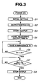
- the operator turns ON the power supply switch 26 and makes an initial setting of a high frequency power value and an output mode or the like when performing treatment as shown in step S1.
- Fig. 2 schematically shows the blood vessel 17 as the living tissue grasped by the electrodes 18a and 18b.
- step S2 the operator turns ON the foot switch 27 as an output switch to perform sealing treatment on the blood vessel 17.
- the output switch may also be provided in the high frequency probe 4.
- the CPU 38 of the control section 38 controls the high frequency current generation section 31 so as to generate a high frequency current.
- the high frequency current generation section 31 outputs the high frequency current from the output end and the high frequency probe 4 transmits the high frequency current and supplies the high frequency current to the blood vessel 17 contacting the electrodes 18a and 18b.
- the high frequency current flows through the blood vessel 17 and sealing treatment starts. That is, the output of the high frequency current in step S3 in Fig. 3 starts.
- step S4 the CPU 38a causes the timer 39 as the time measuring section to start measurement (counting) of the output time Ta of the high frequency current.
- step S5 the CPU 38a takes in the impedance Za detected (measured) by the impedance detection section 37 in a predetermined cycle.
- the CPU 38a judges whether or not the impedance Za taken in has reached a preset second threshold Zs, that is, Za ⁇ Zs.
- step S7 the CPU 38a judges whether or not the output time Ta measured by the timer 39 has reached the first threshold Tm, that is, judges whether or not Ta ⁇ Tm.
- step S7 is processing of substantially judging whether or not Za ⁇ Zs and Ta ⁇ Tm.
- step S7 When the judgment result in step S7 does not satisfy Ta ⁇ Tm (that is, Ta ⁇ Tm), the CPU 38a returns to the processing in step S7. On the other hand, when the judgment result shows that the condition of Ta ⁇ Tm is satisfied, the CPU 38a moves to the processing in step S8. In step S8, the CPU 38a performs control of stopping the output. The CPU 38a then ends the control processing on the sealing treatment in Fig. 3 .
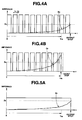
- Fig. 4A illustrates a typical variation of the impedance Za when the high frequency current is set to an intermittent output mode and sealing treatment is applied to a large diameter blood vessel.
- the horizontal axis shows time t and the vertical axis shows an impedance.
- Fig. 4A (the same applies to Fig. 4B or the like) also illustrates a situation in which a high frequency current is intermittently outputted in the intermittent output mode.
- the present embodiment has such a setting that a first period T 1 for outputting a high frequency current intermittently and a second period T2 for stopping the output, the first period T 1 and the second period T2 forming a cycle, are set to 2:1.
- the periods T1 and T2 are set to 60 ms and 30 ms respectively.
- the high frequency current is set to a constant power value.
- FIG. 4B A typical variation of the impedance Za when sealing treatment is applied to a small diameter blood vessel under output conditions similar to those in the case with Fig. 4A is as shown in Fig. 4B .
- the value of impedance Za increases relatively slowly.
- the impedance Za is smaller than the second threshold Zs even when the output time Ta reaches the first threshold Tm.
- the intermittent output mode continues even when the time exceeds the first threshold Tm.
- the output is stopped when the impedance Za reaches (exceeds) the second threshold Zs.
- the value of impedance Za increases earlier.
- the impedance Za exceeds the second threshold Zs before the output time Ta reaches the first threshold Tm.
- the output is stopped.
- the intermittent output is stopped at timing at which the output time Ta exceeds the first threshold Tm, the output may also be stopped at timing slightly delayed as shown by a dotted line.
- Fig. 4A and Fig. 4B illustrate a case where sealing treatment is applied to in the intermittent output mode
- treatment may also be performed in a continuous output mode.
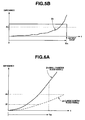
- Fig. 5A and Fig. 5B illustrate a typical variation of impedance Za when sealing treatment is applied to a large diameter blood vessel and a small diameter blood vessel in the continuous output mode.
- the tendency (situation) of variation of impedance Za when treatment is performed in the continuous output mode is similar to that in the case described in Fig. 4A and Fig. 4B .
- the present embodiment sets the first threshold Tm corresponding to the output time Ta and the second threshold Zs corresponding to the value of impedance Za, performs sealing treatment with a high frequency current, and can thereby appropriately perform sealing treatment on the blood vessel 17 of small (to be more specific, on the order of 1 mm) to large diameter (to be more specific, on the order of 7 mm).
- the operator can smoothly perform sealing treatment on the blood vessel 17 and the burden on the operator when performing sealing treatment can be alleviated. Furthermore, since sealing treatment can be performed smoothly, the surgery time can be reduced.
- a common sealing mechanism includes concrescence and coagulation.
- sealing can be realized through coagulation by dehydration of removing water content, but in the case of a large diameter blood vessel, sealing is realized using concrescence whereby mainly collagen in the blood vessel is heated and liquefied.
- sealing characteristics do not deteriorate even when the treatment time extends, whereas sealing characteristics are affected in the case of the large diameter blood vessel.
- a solid line and a dotted line in Fig. 6A schematically indicate variations of impedances Z1 and Z2 of the small diameter blood vessel and the large diameter blood vessel when a high frequency current is supplied under the same condition to seal the small diameter blood vessel and the large diameter blood vessel.
- the horizontal axis shows time t during which sealing treatment is being performed.
- the impedances Z 1 and Z2 greatly differ from each other in variation, and therefore the method in the prior art of detecting an impedance value, stopping the output when the value reaches a preset threshold and ending the sealing treatment is limited to cases in a narrow range of blood vessel diameter.
- a characteristic Qa shown by a two-dot dashed line in Fig. 6B schematically illustrates sealing performance when the diameter of blood vessel is changed when a threshold (A) of impedance is set as a control parameter in the case with a medium diameter blood vessel (M) so as to obtain sealing performance that exceeds target performance.
- the characteristic Qa results in sealing performance lower than required target performance in the cases of small diameter blood vessel (S) and large diameter blood vessel (L).
- the present embodiment uses the threshold Tm of the output time in addition to the threshold Zs of impedance as a control parameter.
- the threshold Zs of impedance is set for a large diameter blood vessel so as to obtain appropriate sealing performance.
- This threshold Zs of impedance may be approximated to be substantially made up of a resistance component only.
- the threshold Tm of the output time is set so as to be able to secure required sealing performance.
- the present embodiment performs output control so as to end the sealing treatment when conditions for both thresholds Tm and Zs are satisfied.
- a characteristic Qb shown by the solid line in Fig. 6B is a characteristic that the threshold Tm of the output time is adjusted (tuned) so as to obtain appropriate sealing performance for a small diameter blood vessel (S).
- a characteristic Qc shown by a thick dotted line is a characteristic that the threshold Zs of impedance is tuned for a large diameter blood vessel (L).
- output control is performed mainly with the characteristic Qb in the case of a small diameter blood vessel, while output control is performed with the characteristic Qc on the large diameter blood vessel side.
- FIG. 6B A case has been described in Fig. 6B where tuning of output time is performed for a small diameter blood vessel and tuning of impedance is performed for a large diameter blood vessel.
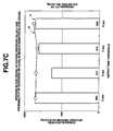
- Fig. 6C illustrates measured data showing grounds when such tuning is performed.
- VBP blood vessel sealing pressure values
- the blood vessel withstand pressure value is a measured value of a pressure when a blood vessel sealed part which is the blood vessel 17 subjected to sealing (treatment) is burst by applying a water pressure thereto in order to objectively evaluate the sealing strength. Since a standard blood pressure of human being is 120 mmHg, sealing performance is considered sufficient when it is possible to obtain a blood vessel withstand pressure value three times that blood pressure, that is 360 mmHg or more.
- Fig. 6C output time control is described as “T control” in abbreviated form and impedance control is described as “Z control” in abbreviated form.
- the measured data in Fig. 6C is an example where the threshold Zs' of impedance is used as a control parameter when an impedance component of a cable such as the high frequency probe 4 for a blood vessel as a living tissue is included, but using the threshold Zs of impedance for only the blood vessel produces a similar result.
- the measured data is actually obtained according to a high frequency surgery control method of a second embodiment.
- the present embodiment performs tuning using the output time in the case of the small diameter blood vessel and performs tuning using impedance in the case of the large diameter blood vessel.
- Fig. 7A illustrates measured data of an average blood vessel withstand pressure value V for determining the threshold Zs' of impedance and a probability P exceeding 360 mmHg when tuning is performed for the large diameter blood vessel. That is, Fig. 7A illustrates measured data obtained when the impedance control described in Fig. 6C is performed by changing the threshold Zs' of impedance.
- the threshold Zs' of impedance may be set in the vicinity of, for example, 650 ⁇ with consideration given to the fact that the probability P exceeding 360 mmHg shown by a polygonal line of is high.
- the threshold Zs' of impedance as a tuning value of impedance is 650 ⁇ and the threshold Zs of net impedance of the blood vessel 17 portion in this case is 925 ⁇ . Therefore, the vicinity of 700 ⁇ to 1100 ⁇ including this value 925 ⁇ may be set to the threshold Zs of impedance of the blood vessel 17 as the living tissue to be treated (to be operated on).
- the probability P that exceeds 360 mmHg in Fig. 7A shows a relative value which is a probability of exceeding 360 mmHg statistically calculated from the blood vessel withstand pressure value obtained.
- Fig. 7B illustrates measured data of an average blood vessel withstand pressure value V for determining the threshold Tm of the output time Ta and the probability P exceeding 360 mmHg when tuning is performed for the small diameter blood vessel. That is, Fig. 7B illustrates measured data obtained when the output time control described in Fig. 6C is performed by changing the threshold Tm of the output time Ta. The upper part in Fig. 7B shows measured data of the probability P exceeding 360 mmHg and the lower part shows the average blood vessel withstand pressure value V.
- the vicinity of 3 seconds to 6 seconds may be set as the threshold Tm of the output time Ta.
- Fig. 7C illustrates measured data of the average blood vessel withstand pressure value V for determining the threshold Tm of output time Ta and the probability P exceeding 360 mmHg when tuning is performed for a medium diameter blood vessel. That is, Fig. 7C illustrates measured data obtained when the output time control described in Fig. 6C is performed by changing the threshold Tm of the output time Ta.
- the configuration of the present embodiment is a configuration similar to that of the first embodiment shown in Fig. 1 and Fig. 2 .
- the CPU 38a of the control section 38 performs output control different from that of the first embodiment.
- sealing treatment is performed in one output mode.
- the CPU 38a performs control so as to use the intermittent output mode when starting the output and switch the mode from the intermittent output mode to the continuous output mode when the detected impedance Za reaches a third threshold Zf of impedance as a control parameter used to switch a preset output mode. That is, in the present embodiment, the CPU 38a has a function of a switching control section (indicated by 38d in Fig. 10 which will be described later) that performs switching control of the output mode.
- the threshold Zf is a value by far smaller than the threshold Zs, to be more specific, on the order of 101 ⁇ .
- the threshold Zf is stored in the memory 40 (see Fig. 2 ).
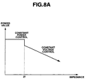
- the present embodiment performs constant power control for the period in the intermittent output mode and performs constant voltage control after reaching the threshold Zf of impedance and shifting to the continuous output mode.
- the constant power control is shifted to the constant voltage control, the amount of high frequency energy injected into the blood vessel 17 is gradually reduced.
- the present embodiment allows sealing treatment to be smoothly performed for any blood vessel of small to large diameter.
- the horizontal axis shows an impedance and the vertical axis shows a power value.
- the threshold Tm of the output time and the threshold Zs of impedance as control parameters are set to 4 seconds and 925 ⁇ respectively by default. Furthermore, the threshold Zf of impedance used for switching between output modes is set to 101 ⁇ by default.
- the intermittent output mode period is set by default such that a high frequency current is outputted in a cycle including 60 ms of ON and 30 ms of OFF with constant power of 40 W. Furthermore, the continuous output mode period is set by default such that a high frequency current is outputted at a constant voltage of 70 Vrms.
- the operator can perform the treatment without changing these values.
- the operator may also operate the setting section 28 to make a selective setting from, for example, 3 seconds of level 1, 4 seconds of level 2 and 5 seconds of level 3, which are prepared in advance, as the threshold Tm of the output time.
- the operator grasps the blood vessel to be treated using the electrodes 18a and 18b at the distal end of the high frequency probe 4 and turns ON the foot switch 27 as the output switch as shown in step S12.
- the CPU 38a of the control section 38 then performs control so as to cause the high frequency current generation section 31 to generate a high frequency current.
- the high frequency power supply apparatus 2 outputs a high frequency current from the output end in the intermittent output mode.
- the high frequency current is transmitted to the blood vessel 17 via the high frequency probe 4, the high frequency current passes through the blood vessel 17 and sealing treatment is started. That is, the output starts in the intermittent output mode.
- step S 14 the CPU 38a causes the timer 39 to start measuring (counting) the output time Ta of the high frequency current.
- step S15 the CPU 38a takes in a detected impedance Za in a predetermined cycle using the impedance detection section 37.
- step S17 the CPU 38a switches (shifts) the high frequency current of the high frequency current generation section 31 from the intermittent output mode to the continuous output mode. Therefore, the high frequency current in the continuous output mode flows through the blood vessel 17.
- next step S18 the CPU 38a takes in the detected (measured) impedance Za from the impedance detection section 37 in a predetermined cycle.
- step S20 the CPU 38a judges whether or not the measured (counted) output time Ta has reached the threshold Tm, that is, Ta ⁇ Tm from the timer 39. Since the judgment result in step S 19 before the judgment in step S20 shows that the condition of Za ⁇ Zs is satisfied, it is substantially judged in step S20 whether or not Za ⁇ Zs and Ta ⁇ Tm.
- step S20 When the judgment result in step S20 shows that Ta ⁇ Tm is not satisfied (that is, Ta ⁇ Tm), the CPU 38a returns to the processing in step S20. On the other hand, when the judgment result shows that the condition of Ta ⁇ Tm is satisfied, the CPU 38a moves to processing in step S21. In step S21, the CPU 38a performs control so as to stop the output. The CPU 38a then ends the control processing on the sealing treatment in Fig. 8B .
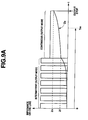
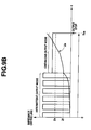
- Fig. 9A and Fig. 9B illustrate a variation of the impedance Za when the high frequency control method in Fig. 8B is applied to a large diameter blood vessel and a small diameter blood vessel.
- the output mode shifts to the continuous output mode. After the shift, even when the output time Ta reaches the threshold Tm of the output time, the impedance Za in the case of the large diameter blood vessel is less than the threshold Zs. Furthermore, when the continuous output mode continues and the impedance Za thereof reaches or exceeds the threshold Zs, the output is stopped.
- the impedance Za increases sooner than in the case of the large diameter blood vessel, and therefore the impedance Za reaches the threshold Zf in a shorter time than in the case of the large diameter blood vessel.
- the output mode shifts to the continuous output mode. After the shift, before the output time Ta reaches the threshold Tm of the output time, the impedance Za thereof exceeds the threshold Zs. Furthermore, the continuous output mode continues and when the output time Ta reaches or exceeds the threshold Tm, the output is stopped.
- the present embodiment allows sealing treatment to be smoothly performed such that a sufficient blood vessel withstand pressure value is obtained for any blood vessel 17 of small to large diameter.
- the aforementioned threshold Tm of output time is a value on the lower limit side of the time set so as to satisfy a target value of the blood vessel withstand pressure value required by sealing treatment and sealing treatment may be performed for a longer time than the threshold Tm in the case of the small diameter blood vessel.
- the impedance Za is smaller than the threshold Zs of impedance during the output time until the threshold Tm, and therefore the value of the threshold Tm may also be set to a value slightly greater than 3 to 6 seconds (on the order of 1 second).
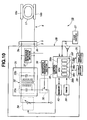
- Fig. 10 illustrates a configuration of a high frequency power supply apparatus 2B in a high frequency surgery apparatus 1B of the present embodiment.
- the CPU 38a making up the control section 38 in the high frequency power supply apparatus 2 in Fig. 2 includes an impedance variation calculation section 38e that calculates an impedance variation ⁇ Za per predetermined time from an impedance Za detected by the impedance detection section 37. Furthermore, the CPU 38a includes a judging section that judges whether or not the calculated impedance variation ⁇ Za is equal to or above a preset threshold ⁇ Zt.
- the CPU 38a has a function of a second output control section 38f that performs output control so as to reduce a high frequency current (or high frequency energy) that performs sealing treatment.
- the output control section 38c may include this function as well.
- the CPU 38a performs output control so that the calculated impedance variation ⁇ Za falls within a predetermined range.
- the CPU 38a also has the function of the switching control section 38d described in the second embodiment.
- the present embodiment corresponds to the second embodiment further provided with the impedance variation calculation section 38e and the second output control section 38f.
- the second output control section 38f reduces a set value of high frequency power during a period in an intermittent output mode and reduces a set value of voltage during a period in a continuous output mode.
- the high frequency power supply apparatus 2B of the present embodiment includes a notifying section 51 that notifies the operator et al., when sealing treatment is performed using control parameters, that the output is not stopped even after a lapse of an allowable output time.
- the CPU 3 8a judges whether or not a threshold Te set to a value greater than the threshold Tm (e.g., 10 seconds) is exceeded.
- a threshold Te set to a value greater than the threshold Tm (e.g., 10 seconds) is exceeded.
- the operator is vocally notified through, for example, a speaker that makes up the notifying section 51 that a standard treatment time has been exceeded.
- Notification is not limited to notification by voice but may also be realized by means of display on a display section 29. After the notification, stoppage of the output may be realized interlocked therewith. Furthermore, the operator may be asked to judge whether or not to stop the output and the stoppage or continuation of the output may be decided according to the judgment result.
- the rest of the configuration is similar to the configuration of the second embodiment.
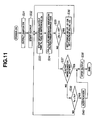
- the processing procedure for output control of the present embodiment corresponding to a case where sealing treatment according to the second embodiment is performed is as shown in Fig. 11 .
- the high frequency surgery apparatus 1B When the power is turned ON, the high frequency surgery apparatus 1B is set in an operating state.
- the operator turns ON the output switch as in step S31, a high frequency current is supplied to a blood vessel to be treated through the high frequency probe 4 as shown in step S32 and the output is started.
- the CPU 38a causes the timer 39 to start to measure an output time Ta and causes the impedance detection section 37 to take in the detected impedance Za.
- the CPU 38a calculates an impedance variation ⁇ Za per predetermined time.
- the predetermined time may also be set to an appropriate time.
- next step S35 the CPU 38a judges whether or not the impedance variation ⁇ Za reaches or exceeds a preset threshold ⁇ Zt. That is, the CPU 38a judges whether or not ⁇ Za ⁇ Zt.
- step S36 the CPU 38a reduces the output by lowering the set power value by a value of X1 or lowering the set voltage value by X2, and then returns to the processing in step S33.
- the set power value is reduced by X1.
- the set power value is 40W
- the set power value is reduced by on the order of several W.
- the judgment condition in step S35 is met during the period in the continuous output mode
- the set voltage value is reduced by X2.
- the set voltage value is 70 Vrms
- the set voltage value is reduced by on the order of 5 Vrms.
- step S35 when the judgment condition in step S35 is not satisfied, the CPU 38a moves to step S37 and in step S37, the CPU 3 8a judges whether or not the output ending condition is satisfied.
- the output ending condition is the judgment processing in step S20 in Fig. 8B .
- step S38 the CPU 38a performs processing of stopping the output and ends the output control in Fig. 11 .
- step S37 In the case of a judgment result that the output ending condition in step S37 is not satisfied, the CPU 38a moves to processing in step S39 and in this step S39, the CPU 38a judges whether or not the output time Ta exceeds a threshold Te close to a maximum value allowable as a preset standard output time. That is, the CPU 38a judges whether or not Ta>Te.
- step S39 the CPU 38a notifies through the notifying section 51 that the standard output time (treatment time) is exceeded and then moves to processing in step S38.
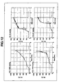
- Fig. 12 illustrates impedance variations in cases with near-best blood vessel withstand pressure values in a plurality of samples sealed according to the second embodiment (samples #10 and #13 on the left) and near-minimum blood vessel withstand pressure values (samples #9 and #14 on the right).
- the present embodiment performs control to reduce the amount of high frequency energy injected so as to prevent such a steep impedance variation from occurring, resulting in an excessive temperature rise on the surface of the tissue.
- the constant power value thereof is reduced by a predetermined power value (X1) at a time through a control loop.
- the impedance variation ⁇ Za exceeds the threshold ⁇ Zt during the period in continuous output mode in which a high frequency current is outputted with a constant voltage value
- the constant voltage value thereof is reduced by a predetermined voltage value (X2) at a time through a control loop.
- the present embodiment not only has effects similar to those of the second embodiment, but also can reduce the probability that an insufficient blood vessel withstand pressure value may be generated when sealing treatment is applied and perform more preferable sealing treatment.
- the present embodiment may also be applied to the first embodiment.
- the present embodiment may reference accumulated past data when sealing treatment is performed, use data such as impedance Za, impedance variation ⁇ Za or the like at each output time Ta obtained when sealing treatment is actually performed, and estimate sealing strength, to be more specific, an evaluation result of blood vessel withstand pressure values as an objective measure of sealing treatment thereof.
- data when known data is not enough to give an evaluation result with predetermined reliability, data may be accumulated until it is possible to give an evaluation result with the predetermined reliability.
- Fig. 13 illustrates a procedure for a high frequency surgery control method designed to notify a blood vessel withstand pressure value as estimated sealing strength after treatment using accumulated data. Since Fig. 13 is only partially different from Fig. 11 , only differences will be described.
- step S51 provided between steps S34 and S35 in Fig. 11 in the processing procedure shown in Fig. 13 , the CPU 38a records the output time Ta, the impedance Za and the impedance variation ⁇ Za in recording means such as the memory 40.
- step S52 after step S36 the CPU 38a records the output time Ta, set power value -X1 or set voltage value -X2 in recording means such as the memory 40.
- step S53 after step S38 the CPU 38a calculates an estimate value of blood vessel withstand pressure value estimated in the case of the blood vessel 17 immediately after treatment is ended based on data such as the output time Ta, the impedance Za, the impedance variation ⁇ Za or the like when sealing treatment is performed in Fig. 13 and the accumulated past data, and displays the estimate value on the display section 29.
- the CPU 38a records the accumulated data (however, data whose blood vessel withstand pressure value is known) in the memory 40 or the like with its characteristics such as the value of impedance Za corresponding to the passage of the output time Ta and the impedance variation ⁇ Za or the like classified into a plurality of patterns.
- the CPU 38a records, for example, an average blood vessel withstand pressure value and reliability thereof in the case of the blood vessel 17 subjected to sealing treatment while being included in each pattern in the memory 40 or the like.
- the CPU 38a judges to which pattern of characteristics the data of the blood vessel 17 subjected to sealing treatment corresponds and calculates an estimate value of the blood vessel withstand pressure value in that case. Furthermore, reliability or the like corresponding to the estimate value is also displayed.
- the operator can confirm a blood vessel withstand pressure value immediately after the treatment through estimation which can be an objective measure (or guideline) when the blood vessel 17 is sealed.
- the blood vessel withstand pressure value through this estimation is assumed to improve reliability as data accumulation advances.
- a judgment result as to whether or not a preset target value (e.g., 360 mmHg) of, for example, the blood vessel withstand pressure value is exceeded and a standard blood vessel withstand pressure value obtained by standard sealing or the like may be displayed or notified together with a value indicating the reliability of the judgment result.
- the operator can also confirm an objective judgment result corresponding to the treatment result.
- the ratio of the ON time to OFF time in the case of, for example, intermittent output is set to 2:1.
- the ON time and OFF time may be changed while keeping this ratio according to the type or the like of the high frequency probe 4.
- An embodiment configured by partially combining the aforementioned embodiments or the like also belongs to the present invention.
Abstract
Description
- The present invention relates to a high frequency surgery apparatus and a surgery control method for performing surgery by passing a high frequency current through a living tissue.
- In recent years, various types of surgery apparatus are used in surgery and the like. For example, a technique of injecting high frequency energy into a blood vessel to perform treatment is conventionally known. In this case, a high frequency surgery apparatus is used which passes a high frequency current through the blood vessel which is being grasped with an appropriate grasping force and seals the blood vessel using thermal energy thereby generated.
- For example, a high frequency surgery apparatus described in Japanese Patent Application Laid-Open Publication No.
2002-325772 - However, according to the method in which the output is stopped when the predetermined electric impedance is reached as described in the above conventional example, it would be difficult to readily perform surgery in a case of performing surgery (or treatment) of sealing with respect to blood vessels different in thickness as target living tissues of the surgery.
- The present invention has been made in view of the above-described point and an object of the present invention is to provide a high frequency surgery apparatus and a surgery control method capable of performing surgery such as sealing even in a case of performing the surgery on different target living tissues.
- A high frequency surgery apparatus according to an aspect of the present invention includes:
- a high frequency current generation section that generates a high frequency current to be transmitted to a living tissue to be operated on;
- a high frequency probe that transmits the high frequency current generated to the living tissue to perform treatment on the living tissue with the high frequency current;
- a time measuring section that measures an output time of the high frequency current of the high frequency current generation section;
- an impedance detection section that detects an electric impedance of the living tissue; and
- an output control section that performs control so as to stop the output of the high frequency current upon detecting that the output time measured by the time measuring section exceeds a first threshold and detecting that the electric impedance value detected by the impedance detection section exceeds a second threshold.
- A high frequency surgery apparatus according to an aspect of the present invention includes:
- a high frequency current generation section that generates a high frequency current to be transmitted to a living tissue to be operated on;
- an impedance detection section that detects an electric impedance of the living tissue to which the high frequency current is transmitted via a high frequency treatment instrument;
- an impedance variation calculation section that calculates an electric impedance variation per predetermined time from the electric impedance value detected by the impedance detection section; and
- an output control section that performs output control on the high frequency current transmitted to the living tissue,
- wherein the output control section performs output control of the high frequency current so that the impedance variation calculated by the impedance variation calculation section falls within a predetermined range.
- A surgery control method according to an aspect of the present invention includes:
- an outputting step of a high frequency current generation section outputting a high frequency current to a living tissue as a target of surgery by operation of a switch;
- a time measuring step of a time measuring section measuring an output time of the high frequency current to the living tissue;
- an impedance detecting step of an impedance detection section chronologically detecting an electric impedance after the high frequency current is outputted to the living tissue;
- a judging step of a judging section judging whether or not a first condition under which the measured output time reaches a first threshold and a second condition under which the detected electric impedance value reaches a second threshold are satisfied; and
- an output controlling step of an output control section performing control so as to stop the output of the high frequency current to the living tissue when the judgment result shows that the first condition and the second condition are satisfied.
-
-
Fig. 1 is a diagram illustrating an overall configuration of a high frequency surgery apparatus according to a first embodiment of the present invention; -
Fig. 2 is a block diagram illustrating an internal configuration of a high frequency power supply apparatus of the high frequency surgery apparatus; -
Fig. 3 is a flowchart illustrating a typical example of high frequency surgery control method for a blood vessel to be treated according to the first embodiment; -
Fig. 4A is an explanatory operation diagram illustrating an impedance variation when sealing treatment is applied to a large diameter blood vessel according to the high frequency surgery control method inFig. 3 through intermittent output; -
Fig. 4B is an explanatory operation diagram illustrating an impedance variation when sealing treatment is applied to a small diameter blood vessel according to the high frequency surgery control method inFig. 3 through intermittent output; -
Fig. 5A is an explanatory operation diagram illustrating an impedance variation when sealing treatment is applied to a large diameter blood vessel according to the high frequency surgery control method inFig. 3 through continuous outputs; -
Fig. 5B is an explanatory operation diagram illustrating an impedance variation when sealing treatment is applied to a small diameter blood vessel according to the high frequency surgery control method inFig. 3 through continuous outputs; -
Fig. 6A is a diagram illustrating an impedance variation when a high frequency current is supplied under the same condition to apply sealing treatment to a small diameter blood vessel and a large diameter blood vessel; -
Fig. 6B is a diagram illustrating the way to realize high sealing performance by setting two control parameters according to the first embodiment; -
Fig. 6C is a diagram illustrating measured data of average blood vessel withstand pressure values when sealing treatment is applied to a large diameter blood vessel and a small diameter blood vessel using an output time threshold and an impedance threshold as control parameters respectively; -
Fig. 7A is a diagram illustrating measured data to determine an impedance threshold as a control parameter in the case of a large diameter blood vessel; -
Fig. 7B is a diagram illustrating measured data to determine an output time threshold as a control parameter in the case of a small diameter blood vessel; -
Fig. 7C is a diagram illustrating measured data to determine an output time threshold as a control parameter in the case of a medium diameter blood vessel; -
Fig. 8A is a diagram illustrating constant power control and constant voltage control when performing output control according to a second embodiment of the present invention; -
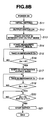
Fig. 8B is a flowchart illustrating a typical example of a high frequency surgery control method for a blood vessel to be treated according to the second embodiment; -
Fig. 9A is an explanatory operation diagram illustrating an impedance variation or the like when sealing treatment is applied to a large diameter blood vessel according to the high frequency surgery control method of the second embodiment; -
Fig. 9B is an explanatory operation diagram illustrating an impedance variation or the like when sealing treatment is applied to a small diameter blood vessel according to the high frequency surgery control method of the second embodiment; -
Fig. 10 is a block diagram illustrating an internal configuration of a high frequency power supply apparatus according to a third embodiment of the present invention; -
Fig. 11 is a flowchart illustrating a processing procedure for exercising output control when performing sealing treatment according to the third embodiment; -
Fig. 12 is a diagram illustrating an example of measured data of an impedance variation in the case of a sample when a near-best blood vessel withstand pressure value is obtained and a sample of a near-minimum blood vessel withstand pressure value; and -
Fig. 13 is a flowchart illustrating a processing procedure when performing sealing treatment in a modification example of the third embodiment. - Hereinafter, embodiments of the present invention will be described with reference to the accompanying drawings.
- As shown in
Fig. 1 , a highfrequency surgery apparatus 1 according to a first embodiment of the present invention includes a high frequencypower supply apparatus 2 provided with a high frequencycurrent generation section 31 that generates a high frequency current for treatment (seeFig. 2 ). - The high frequency
power supply apparatus 2 is provided with aconnector receiver 3 that outputs a high frequency current generated and aconnector 5 provided at a proximal end of aconnection cable 4a of ahigh frequency probe 4 is detachably connected to theconnector receiver 3 as a high frequency treatment instrument. - The
high frequency probe 4 includes anoperation section 6 for an operator to grasp to operate, asheath 7 that extends from a top end of theoperation section 6 and atreatment section 9 provided via alink mechanism 8 at a distal end of thesheath 7 to pass a high frequency current through a living tissue to be treated and perform treatment of high frequency surgery. - A
slide pipe 10 is inserted into thesheath 7 and a rear end of theslide pipe 10 is connected to a connection bearing 13 at one top end ofhandles operation section 6 via aconnection shaft 11. Theconnection bearing 13 is provided with aslit 13a that allows a rear end side of theconnection shaft 11 to pass and does not allow its spherical portion at the rear end to pass. - The
handles section 14 and are provided withfinger hooking members - When the operator performs operation of opening or closing the
finger hooking members handles slide pipe 10. - A distal end of the
slide pipe 10 is connected to a pair oftreatment members treatment section 9 via alink mechanism 8 for opening/closing. - Therefore, the operator performs operation of opening/closing the
handles link mechanism 8 connected to theslide pipe 10 that moves forward/backward and open/close the pair oftreatment members blood vessel 17 as the living tissue to be treated can be grasped using the two mutually facing inner surface parts of the pair oftreatment members Fig. 2 ). - The state in
Fig. 1 is a state in which thehandles handles slide pipe 10 moves forward and the pair oftreatment members link mechanism 8. - The pair of
treatment members bipolar electrodes treatment members link mechanism 8. - A pair of
signal lines 21 are passed through theslide pipe 10 and connected to theelectrodes signal line 21 is connected to aconnector receiver 23 provided, for example, at a top of thehandle 12b. A connector at the other end of theconnection cable 4a is detachably connected to theconnector receiver 23. - A
foot switch 27 as an output switch that performs operation of instructing output ON (energization) or output OFF (disconnection) of a high frequency current is connected to the high frequencypower supply apparatus 2, in addition to apower supply switch 26. The operator can step on thefoot switch 27 with the foot to thereby supply or stop supplying the high frequency current to thetreatment section 9. - Furthermore, a
setting section 28 for setting a high frequency power value or the like is provided on the front of the high frequencypower supply apparatus 2. Thesetting section 28 is provided with apower setting button 28a that sets a high frequency power value and aselection switch 28b that selects one of an intermittent output mode in which a high frequency current is outputted intermittently and a continuous output mode in which a high frequency current is outputted continuously. The operator is allowed to set a high frequency power value suitable for treatment and set an output mode used to perform high frequency surgery. - A
display section 29 that displays the set high frequency power value or the like is provided above thesetting section 28. - As shown in
Fig. 2 , the high frequencypower supply apparatus 2 is configured by a high frequencycurrent generation section 31 that generates a high frequency current to be transmitted to a living tissue to be operated on using aninsulation transformer 32. Aparallel resonance circuit 33a to which a capacitor is connected in parallel is provided on a primary wiring side of theinsulation transformer 32. A DC voltage is applied to one end of theparallel resonance circuit 33a from avariable power supply 34 and aswitching circuit 35 is connected to the other end thereof. - The
variable power supply 34 can change and output the DC voltage. Furthermore, the switchingcircuit 35 performs switching through application of a switching control signal from awaveform generation section 36. - The switching
circuit 35 switches a current that flows from thevariable power supply 34 to the primary wiring of theinsulation transformer 32 and generates a voltage-boosted high frequency current at anoutput section 33b on a secondary wiring side of theinsulation transformer 32 insulated from the primary wiring side. A capacitor is also connected to the secondary wiring. - The
output section 33b on the secondary wiring side of theinsulation transformer 32 is connected tocontacts connector receiver 3 which is an output end of the high frequency current. Treatment such as sealing can be performed by transmitting a high frequency current via thehigh frequency probe 4 connected to theconnector receiver 3 and supplying (applying) the high frequency current to ablood vessel 17 as a living tissue to be operated on. - Furthermore, both ends of the
output section 33b are connected to animpedance detection section 37. Theimpedance detection section 37 detects a voltage between output ends (twocontacts blood vessel 17 as the living tissue as shown inFig. 2 and a current that flows through theblood vessel 17 which becomes a load and detects an electric impedance (simply abbreviated as "impedance") obtained by dividing the voltage in that case by the current. Theimpedance detection section 37 outputs the detected impedance to acontrol section 38. As will be described later, theimpedance detection section 37 may also be configured so as to further calculate an impedance Za of theblood vessel 17 portion and output the impedance Za to thecontrol section 38. - Furthermore, the
control section 38 is connected to atimer 39 as a time measuring section that measures time, amemory 40 that stores various kinds of information, thefoot switch 27 that turns ON or OFF the output of a high frequency current, thesetting section 28 and thedisplay section 29. - The
control section 38 that controls the sections of the high frequencypower supply apparatus 2 sends setting conditions and control signals corresponding to the impedance detected by theimpedance detection section 37 and the measured time by thetimer 39 to thevariable power supply 34 and thewaveform generation section 36. - The
variable power supply 34 outputs DC power corresponding to the control signal sent from thecontrol section 38. Furthermore, thewaveform generation section 36 outputs a waveform (here, square wave) corresponding to the control signal sent from thecontrol section 38. - The high frequency
current generation section 31 generates a high frequency current through the operation of the switchingcircuit 35, which is turned ON or OFF by the DC power sent from thevariable power supply 34 and the square wave sent from thewaveform generation section 36 and outputs the high frequency current from theconnector receiver 3. Theparallel resonance circuit 33a reduces spurious caused by the square wave obtained through the switching operation. Theoutput section 33b also forms a resonance circuit and reduces spurious. - The
control section 38 is constructed, for example, of aCPU 38a and theCPU 38a controls the respective sections when performing treatment such as sealing on theblood vessel 17 according to the program stored in thememory 40. - In the present embodiment, in order to be able to appropriately perform sealing treatment on any
blood vessel 17 of small to large diameter, thememory 40 stores a first threshold Tm of output time and a second threshold Zs of impedance as control parameters for appropriately performing sealing treatment. - In order to detect impedance at the
connector receiver 3 to which theconnector 5 at the proximal end of thehigh frequency probe 4 is connected, theimpedance detection section 37 actually detects a net impedance Za of theblood vessel 17 at theelectrodes high frequency probe 4. - The present embodiment will describe that the
impedance detection section 37 further calculates the net impedance Za from the impedance Za' and outputs the impedance Za to theCPU 38a. This processing may also be performed by theCPU 28a. Hereinafter, suppose theimpedance detection section 37 calculates (detects) the net impedance Za of theblood vessel 17 at theelectrodes CPU 38a. - The impedance threshold Zs stored in the
memory 40 is a threshold set for the net impedance of theblood vessel 17 at theelectrodes - When the threshold Zs' itself that corresponds to the impedance Za' detected through the measurement by the
impedance detection section 37 is used instead of the threshold Zs, the impedance Za' may be compared with the threshold Zs'. - As will be described below, upon starting treatment with high frequency energy, the
CPU 38a of thecontrol section 38 has the function of thejudging section 38b that measures an output time Ta via thetimer 39, judges whether or not the output time Ta has reached the threshold Tm and judges whether or not the impedance Za detected by theimpedance detection section 37 has reached the second threshold Zs. - Upon judging that the condition of having reached the first threshold Tm and the condition of having reached the second threshold Zs are satisfied, the
CPU 38a has the function of theoutput control section 38c that performs output control of stopping the output of the high frequency current from the high frequencycurrent generation section 31. - Next, the operation when performing treatment of sealing the
blood vessel 17 using thehigh frequency probe 4 according to the present embodiment will be described with reference to a flowchart inFig. 3 . - The operator turns ON the
power supply switch 26 and makes an initial setting of a high frequency power value and an output mode or the like when performing treatment as shown in step S1. - Furthermore, the operator grasps the
blood vessel 17 as a living tissue to be treated using theelectrodes treatment section 9 at the distal end portion of thehigh frequency probe 4 shown inFig. 1 .Fig. 2 schematically shows theblood vessel 17 as the living tissue grasped by theelectrodes - As shown in step S2, the operator turns ON the
foot switch 27 as an output switch to perform sealing treatment on theblood vessel 17. The output switch may also be provided in thehigh frequency probe 4. - When the output switch is turned ON, the
CPU 38 of thecontrol section 38 controls the high frequencycurrent generation section 31 so as to generate a high frequency current. The high frequencycurrent generation section 31 outputs the high frequency current from the output end and thehigh frequency probe 4 transmits the high frequency current and supplies the high frequency current to theblood vessel 17 contacting theelectrodes blood vessel 17 and sealing treatment starts. That is, the output of the high frequency current in step S3 inFig. 3 starts. - At this moment, as shown in step S4, the
CPU 38a causes thetimer 39 as the time measuring section to start measurement (counting) of the output time Ta of the high frequency current. - Furthermore, as shown in step S5, the
CPU 38a takes in the impedance Za detected (measured) by theimpedance detection section 37 in a predetermined cycle. - As shown in next step S6, the
CPU 38a judges whether or not the impedance Za taken in has reached a preset second threshold Zs, that is, Za≥Zs. - When the condition of Za≥Zs is not satisfied (that is, Za<Zs), the
CPU 38a returns to the processing in step S5. - On the other hand, when the judgment result shows that the condition of Za≥Zs is satisfied, the
CPU 38a moves to processing in step S7. In step S7, theCPU 38a judges whether or not the output time Ta measured by thetimer 39 has reached the first threshold Tm, that is, judges whether or not Ta≥Tm. When theCPU 38a performs judgment in step S7, since the judgment in step S6 has already proved that the condition of Za≥Zs is satisfied, step S7 is processing of substantially judging whether or not Za≥Zs and Ta≥Tm. - When the judgment result in step S7 does not satisfy Ta≥Tm (that is, Ta<Tm), the
CPU 38a returns to the processing in step S7. On the other hand, when the judgment result shows that the condition of Ta≥Tm is satisfied, theCPU 38a moves to the processing in step S8. In step S8, theCPU 38a performs control of stopping the output. TheCPU 38a then ends the control processing on the sealing treatment inFig. 3 . -
Fig. 4A illustrates a typical variation of the impedance Za when the high frequency current is set to an intermittent output mode and sealing treatment is applied to a large diameter blood vessel. Here, the horizontal axis shows time t and the vertical axis shows an impedance.Fig. 4A (the same applies toFig. 4B or the like) also illustrates a situation in which a high frequency current is intermittently outputted in the intermittent output mode. - In the case of the intermittent output mode, the present embodiment has such a setting that a
first period T 1 for outputting a high frequency current intermittently and a second period T2 for stopping the output, thefirst period T 1 and the second period T2 forming a cycle, are set to 2:1. The periods T1 and T2 are set to 60 ms and 30 ms respectively. Furthermore, during the period in this intermittent output mode, the high frequency current is set to a constant power value. - A typical variation of the impedance Za when sealing treatment is applied to a small diameter blood vessel under output conditions similar to those in the case with
Fig. 4A is as shown inFig. 4B . - As is clear from
Fig. 4A and Fig. 4B , when treatment is applied to the large diameter blood vessel, the value of impedance Za increases relatively slowly. The impedance Za is smaller than the second threshold Zs even when the output time Ta reaches the first threshold Tm. - Thus, the intermittent output mode continues even when the time exceeds the first threshold Tm. The output is stopped when the impedance Za reaches (exceeds) the second threshold Zs.
- On the other hand, in the case of the treatment on the small diameter blood vessel, compared to the case with the large diameter blood vessel, the value of impedance Za increases earlier. The impedance Za exceeds the second threshold Zs before the output time Ta reaches the first threshold Tm.
- When the intermittent output mode continues with the value of impedance Za exceeding the second threshold Zs and the output time Ta reaches (exceeds) the first threshold Tm, the output is stopped. In
Fig. 4B , if the intermittent output is stopped at timing at which the output time Ta exceeds the first threshold Tm, the output may also be stopped at timing slightly delayed as shown by a dotted line. - Although
Fig. 4A and Fig. 4B illustrate a case where sealing treatment is applied to in the intermittent output mode, treatment may also be performed in a continuous output mode. -
Fig. 5A andFig. 5B illustrate a typical variation of impedance Za when sealing treatment is applied to a large diameter blood vessel and a small diameter blood vessel in the continuous output mode. - The tendency (situation) of variation of impedance Za when treatment is performed in the continuous output mode is similar to that in the case described in
Fig. 4A and Fig. 4B . - As described above, the present embodiment sets the first threshold Tm corresponding to the output time Ta and the second threshold Zs corresponding to the value of impedance Za, performs sealing treatment with a high frequency current, and can thereby appropriately perform sealing treatment on the
blood vessel 17 of small (to be more specific, on the order of 1 mm) to large diameter (to be more specific, on the order of 7 mm). - Thus, the operator can smoothly perform sealing treatment on the
blood vessel 17 and the burden on the operator when performing sealing treatment can be alleviated. Furthermore, since sealing treatment can be performed smoothly, the surgery time can be reduced. - The effectiveness in performing such control according to the present invention will be described below. As is clear from characteristics of variation of impedance Za in
Fig. 4A to Fig. 5B , in the case of a small diameter blood vessel, the value of impedance Za increases together with the output time Ta in a shorter time than in the case of a large diameter blood vessel. - A common sealing mechanism includes concrescence and coagulation. In the case of a small diameter blood vessel, sealing can be realized through coagulation by dehydration of removing water content, but in the case of a large diameter blood vessel, sealing is realized using concrescence whereby mainly collagen in the blood vessel is heated and liquefied.
- Thus, in the case of the small diameter blood vessel, sealing characteristics do not deteriorate even when the treatment time extends, whereas sealing characteristics are affected in the case of the large diameter blood vessel.
- A solid line and a dotted line in
Fig. 6A schematically indicate variations of impedances Z1 and Z2 of the small diameter blood vessel and the large diameter blood vessel when a high frequency current is supplied under the same condition to seal the small diameter blood vessel and the large diameter blood vessel. The horizontal axis shows time t during which sealing treatment is being performed. - As shown in
Fig. 6A , theimpedances Z 1 and Z2 greatly differ from each other in variation, and therefore the method in the prior art of detecting an impedance value, stopping the output when the value reaches a preset threshold and ending the sealing treatment is limited to cases in a narrow range of blood vessel diameter. - A characteristic Qa shown by a two-dot dashed line in
Fig. 6B schematically illustrates sealing performance when the diameter of blood vessel is changed when a threshold (A) of impedance is set as a control parameter in the case with a medium diameter blood vessel (M) so as to obtain sealing performance that exceeds target performance. - The characteristic Qa results in sealing performance lower than required target performance in the cases of small diameter blood vessel (S) and large diameter blood vessel (L).
- Thus, the present embodiment uses the threshold Tm of the output time in addition to the threshold Zs of impedance as a control parameter. As shown in
Fig. 6A , the threshold Zs of impedance is set for a large diameter blood vessel so as to obtain appropriate sealing performance. This threshold Zs of impedance may be approximated to be substantially made up of a resistance component only. - In the case of the small diameter blood vessel as shown in
Fig. 6A , the threshold Tm of the output time is set so as to be able to secure required sealing performance. The present embodiment performs output control so as to end the sealing treatment when conditions for both thresholds Tm and Zs are satisfied. - An overview of sealing performance in this case is as shown by a solid line and a thick dotted line in
Fig. 6B . A characteristic Qb shown by the solid line inFig. 6B is a characteristic that the threshold Tm of the output time is adjusted (tuned) so as to obtain appropriate sealing performance for a small diameter blood vessel (S). - Furthermore, a characteristic Qc shown by a thick dotted line is a characteristic that the threshold Zs of impedance is tuned for a large diameter blood vessel (L). By performing output control so as to satisfy both thresholds Tm and Zs, sealing performance that exceeds target performance can be achieved as shown in
Fig. 6B . To be more specific, output control is performed mainly with the characteristic Qb in the case of a small diameter blood vessel, while output control is performed with the characteristic Qc on the large diameter blood vessel side. - A case has been described in
Fig. 6B where tuning of output time is performed for a small diameter blood vessel and tuning of impedance is performed for a large diameter blood vessel.Fig. 6C illustrates measured data showing grounds when such tuning is performed. - Two bars on the left and two bars on the right in
Fig. 6C illustrate average blood vessel sealing pressure values (VBP) [mmHg] when sealing treatment is applied using a threshold of output time (4 seconds in a specific example) and a threshold of impedance (where Zs' is 670Ω 890Ω) as control parameters in the cases of a large diameter blood vessel and a small diameter blood vessel respectively. - The blood vessel withstand pressure value is a measured value of a pressure when a blood vessel sealed part which is the
blood vessel 17 subjected to sealing (treatment) is burst by applying a water pressure thereto in order to objectively evaluate the sealing strength. Since a standard blood pressure of human being is 120 mmHg, sealing performance is considered sufficient when it is possible to obtain a blood vessel withstand pressure value three times that blood pressure, that is 360 mmHg or more. - Furthermore, in
Fig. 6C , output time control is described as "T control" in abbreviated form and impedance control is described as "Z control" in abbreviated form. Furthermore, the measured data inFig. 6C is an example where the threshold Zs' of impedance is used as a control parameter when an impedance component of a cable such as thehigh frequency probe 4 for a blood vessel as a living tissue is included, but using the threshold Zs of impedance for only the blood vessel produces a similar result. The measured data is actually obtained according to a high frequency surgery control method of a second embodiment. - In the case of the large diameter blood vessel, it is obvious from the measured data that impedance control is more effective than output time control.
- On the other hand, in the case of the small diameter blood vessel, it is obvious that output time control is more effective than impedance control.
- Thus, as described in
Fig. 6B , the present embodiment performs tuning using the output time in the case of the small diameter blood vessel and performs tuning using impedance in the case of the large diameter blood vessel. - Furthermore,
Fig. 7A illustrates measured data of an average blood vessel withstand pressure value V for determining the threshold Zs' of impedance and a probability P exceeding 360 mmHg when tuning is performed for the large diameter blood vessel. That is,Fig. 7A illustrates measured data obtained when the impedance control described inFig. 6C is performed by changing the threshold Zs' of impedance. - It is obvious from the measured data in
Fig. 7A that the threshold Zs' of impedance may be set in the vicinity of, for example, 650Ω with consideration given to the fact that the probability P exceeding 360 mmHg shown by a polygonal line of is high. - That is, the threshold Zs' of impedance as a tuning value of impedance is 650Ω and the threshold Zs of net impedance of the
blood vessel 17 portion in this case is 925Ω. Therefore, the vicinity of 700Ω to 1100Ω including this value 925Ω may be set to the threshold Zs of impedance of theblood vessel 17 as the living tissue to be treated (to be operated on). - The probability P that exceeds 360 mmHg in
Fig. 7A shows a relative value which is a probability of exceeding 360 mmHg statistically calculated from the blood vessel withstand pressure value obtained. - Furthermore,
Fig. 7B illustrates measured data of an average blood vessel withstand pressure value V for determining the threshold Tm of the output time Ta and the probability P exceeding 360 mmHg when tuning is performed for the small diameter blood vessel. That is,Fig. 7B illustrates measured data obtained when the output time control described inFig. 6C is performed by changing the threshold Tm of the output time Ta. The upper part inFig. 7B shows measured data of the probability P exceeding 360 mmHg and the lower part shows the average blood vessel withstand pressure value V. - From the measured data in
Fig. 7B , for example, the vicinity of 3 seconds to 6 seconds may be set as the threshold Tm of the output time Ta. - Furthermore,
Fig. 7C illustrates measured data of the average blood vessel withstand pressure value V for determining the threshold Tm of output time Ta and the probability P exceeding 360 mmHg when tuning is performed for a medium diameter blood vessel. That is,Fig. 7C illustrates measured data obtained when the output time control described inFig. 6C is performed by changing the threshold Tm of the output time Ta. - In the measured data in
Fig. 7C , although the average blood vessel withstand pressure value V in the case of 4 seconds is somewhat low, since a value nearly twice 360 mmHg is maintained in this case too, any value in the vicinity of, for example, 3 seconds to 6 seconds may be adopted as the threshold Tm of the output time Ta. - Using two control parameters set in this way, it is possible to smoothly perform sealing treatment in the case of any
blood vessel 17 of small to large diameter according to the present embodiment as described above. Furthermore, according to the present embodiment, it is possible to perform sealing treatment simply and in a short time in the case of anyblood vessel 17 of small to large diameter and alleviate the burden on the operator and patient. - Next, a second embodiment of the present invention will be described. The configuration of the present embodiment is a configuration similar to that of the first embodiment shown in
Fig. 1 andFig. 2 . - The
CPU 38a of thecontrol section 38 according to the present embodiment performs output control different from that of the first embodiment. In the first embodiment, sealing treatment is performed in one output mode. - By contrast, in the present embodiment, the
CPU 38a performs control so as to use the intermittent output mode when starting the output and switch the mode from the intermittent output mode to the continuous output mode when the detected impedance Za reaches a third threshold Zf of impedance as a control parameter used to switch a preset output mode. That is, in the present embodiment, theCPU 38a has a function of a switching control section (indicated by 38d inFig. 10 which will be described later) that performs switching control of the output mode. The threshold Zf is a value by far smaller than the threshold Zs, to be more specific, on the order of 101Ω. The threshold Zf is stored in the memory 40 (seeFig. 2 ). - As shown in
Fig. 8A , the present embodiment performs constant power control for the period in the intermittent output mode and performs constant voltage control after reaching the threshold Zf of impedance and shifting to the continuous output mode. When the constant power control is shifted to the constant voltage control, the amount of high frequency energy injected into theblood vessel 17 is gradually reduced. - By switching between the output modes in this way, the present embodiment allows sealing treatment to be smoothly performed for any blood vessel of small to large diameter. In
Fig. 8A , the horizontal axis shows an impedance and the vertical axis shows a power value. - Next, a high frequency surgery control method according to the present embodiment will be described with reference to
Fig. 8B . After turning ON the power, the operator makes an initial setting infirst step S 11. - In the present embodiment, the threshold Tm of the output time and the threshold Zs of impedance as control parameters are set to 4 seconds and 925Ω respectively by default. Furthermore, the threshold Zf of impedance used for switching between output modes is set to 101Ω by default.
- Furthermore, the intermittent output mode period is set by default such that a high frequency current is outputted in a cycle including 60 ms of ON and 30 ms of OFF with constant power of 40 W. Furthermore, the continuous output mode period is set by default such that a high frequency current is outputted at a constant voltage of 70 Vrms.
- Therefore, when performing sealing treatment with the default setting as is, the operator can perform the treatment without changing these values. The operator may also operate the
setting section 28 to make a selective setting from, for example, 3 seconds oflevel level level 3, which are prepared in advance, as the threshold Tm of the output time. - The operator grasps the blood vessel to be treated using the
electrodes high frequency probe 4 and turns ON thefoot switch 27 as the output switch as shown in step S12. TheCPU 38a of thecontrol section 38 then performs control so as to cause the high frequencycurrent generation section 31 to generate a high frequency current. - As shown in
step S 13, the high frequencypower supply apparatus 2 outputs a high frequency current from the output end in the intermittent output mode. The high frequency current is transmitted to theblood vessel 17 via thehigh frequency probe 4, the high frequency current passes through theblood vessel 17 and sealing treatment is started. That is, the output starts in the intermittent output mode. - In this case, as shown in
step S 14, theCPU 38a causes thetimer 39 to start measuring (counting) the output time Ta of the high frequency current. - Furthermore, as shown in step S15, the
CPU 38a takes in a detected impedance Za in a predetermined cycle using theimpedance detection section 37. - As shown in next step S16, the
CPU 38a judges whether or not the impedance Za taken in has reached a preset threshold Zf (to be more specific, Zf=101Ω), that is, Za≥Zf. - When the condition of Za≥Zf is not satisfied (that is, Za<Zf), the
CPU 38a returns to the processing in step S 15. - On the other hand, when the judgment result shows that the condition of Za≥Zf is satisfied, the
CPU 38a moves to processing in step S17. In step S17, theCPU 38a switches (shifts) the high frequency current of the high frequencycurrent generation section 31 from the intermittent output mode to the continuous output mode. Therefore, the high frequency current in the continuous output mode flows through theblood vessel 17. - Furthermore, in next step S18, the
CPU 38a takes in the detected (measured) impedance Za from theimpedance detection section 37 in a predetermined cycle. - As shown in next step S19, the
CPU 38a judges whether or not the impedance Za taken in has reached the preset threshold Zs (to be more specific, Zs=925Ω), that is, Za≥Zs. - When the condition of Za≥Zs is not satisfied (that is, Za<Zs), the
CPU 38a returns to the processing in step S 18. - On the other hand, when the judgment result shows that the condition of Za≥Zs is satisfied, the
CPU 38a moves to processing in step S20. In step S20, theCPU 38a judges whether or not the measured (counted) output time Ta has reached the threshold Tm, that is, Ta≥Tm from thetimer 39. Since the judgment result in step S 19 before the judgment in step S20 shows that the condition of Za≥Zs is satisfied, it is substantially judged in step S20 whether or not Za≥Zs and Ta≥Tm. - When the judgment result in step S20 shows that Ta≥Tm is not satisfied (that is, Ta<Tm), the
CPU 38a returns to the processing in step S20. On the other hand, when the judgment result shows that the condition of Ta≥Tm is satisfied, theCPU 38a moves to processing in step S21. In step S21, theCPU 38a performs control so as to stop the output. TheCPU 38a then ends the control processing on the sealing treatment inFig. 8B . -
Fig. 9A andFig. 9B illustrate a variation of the impedance Za when the high frequency control method inFig. 8B is applied to a large diameter blood vessel and a small diameter blood vessel. - As is clear from a comparison of
Fig. 9A andFig. 9B , since the impedance Za increases more slowly in the case of the large diameter blood vessel than in the case of the small diameter blood vessel, the time until the impedance Za reaches the threshold Zf is longer than in the case of the small diameter blood vessel. Therefore, in the case of the large diameter blood vessel, the treatment time in the intermittent output mode is longer than in the case of the small diameter blood vessel. - When the impedance Za reaches the threshold Zf, the output mode shifts to the continuous output mode. After the shift, even when the output time Ta reaches the threshold Tm of the output time, the impedance Za in the case of the large diameter blood vessel is less than the threshold Zs. Furthermore, when the continuous output mode continues and the impedance Za thereof reaches or exceeds the threshold Zs, the output is stopped.
- On the other hand, in the case of the small diameter blood vessel, the impedance Za increases sooner than in the case of the large diameter blood vessel, and therefore the impedance Za reaches the threshold Zf in a shorter time than in the case of the large diameter blood vessel.
- When the impedance Za reaches the threshold Zf, the output mode shifts to the continuous output mode. After the shift, before the output time Ta reaches the threshold Tm of the output time, the impedance Za thereof exceeds the threshold Zs. Furthermore, the continuous output mode continues and when the output time Ta reaches or exceeds the threshold Tm, the output is stopped.
- The present embodiment allows sealing treatment to be smoothly performed such that a sufficient blood vessel withstand pressure value is obtained for any
blood vessel 17 of small to large diameter. - In the case of the small diameter blood vessel, the aforementioned threshold Tm of output time is a value on the lower limit side of the time set so as to satisfy a target value of the blood vessel withstand pressure value required by sealing treatment and sealing treatment may be performed for a longer time than the threshold Tm in the case of the small diameter blood vessel.
- Furthermore, in the case of the large diameter blood vessel, the impedance Za is smaller than the threshold Zs of impedance during the output time until the threshold Tm, and therefore the value of the threshold Tm may also be set to a value slightly greater than 3 to 6 seconds (on the order of 1 second).
- Next, a third embodiment of the present invention will be described. The configuration of the present embodiment is a configuration similar to that of the first embodiment shown in
Fig. 1 andFig. 2 .Fig. 10 illustrates a configuration of a high frequencypower supply apparatus 2B in a highfrequency surgery apparatus 1B of the present embodiment. - In the high frequency
power supply apparatus 2B, theCPU 38a making up thecontrol section 38 in the high frequencypower supply apparatus 2 inFig. 2 includes an impedancevariation calculation section 38e that calculates an impedance variation ΔZa per predetermined time from an impedance Za detected by theimpedance detection section 37. Furthermore, theCPU 38a includes a judging section that judges whether or not the calculated impedance variation ΔZa is equal to or above a preset threshold ΔZt. - Furthermore, upon judging that the calculated impedance variation ΔZa is equal to or above the preset threshold ΔZt, the
CPU 38a has a function of a secondoutput control section 38f that performs output control so as to reduce a high frequency current (or high frequency energy) that performs sealing treatment. Theoutput control section 38c may include this function as well. - In other words, the
CPU 38a performs output control so that the calculated impedance variation ΔZa falls within a predetermined range. - When calculating the impedance variation ΔZa, the value of the predetermined time is set to, for example, on the order of several tens of ms to 100 ms. Furthermore, the threshold ΔZt is set to a value on the order of 200Ω/200 ms (=1kΩ/s) or slightly smaller than this value. The threshold ΔZt is set based on measured data shown in
Fig. 12 which will be described later. - The
CPU 38a also has the function of the switchingcontrol section 38d described in the second embodiment. - Therefore, the present embodiment corresponds to the second embodiment further provided with the impedance
variation calculation section 38e and the secondoutput control section 38f. - The second
output control section 38f reduces a set value of high frequency power during a period in an intermittent output mode and reduces a set value of voltage during a period in a continuous output mode. - The high frequency
power supply apparatus 2B of the present embodiment includes a notifyingsection 51 that notifies the operator et al., when sealing treatment is performed using control parameters, that the output is not stopped even after a lapse of an allowable output time. - To be more specific, when a threshold Tm of an output time Ta has elapsed, the
CPU 3 8a judges whether or not a threshold Te set to a value greater than the threshold Tm (e.g., 10 seconds) is exceeded. When the threshold Te is exceeded, the operator is vocally notified through, for example, a speaker that makes up the notifyingsection 51 that a standard treatment time has been exceeded. - Notification is not limited to notification by voice but may also be realized by means of display on a
display section 29. After the notification, stoppage of the output may be realized interlocked therewith. Furthermore, the operator may be asked to judge whether or not to stop the output and the stoppage or continuation of the output may be decided according to the judgment result. - The rest of the configuration is similar to the configuration of the second embodiment. The processing procedure for output control of the present embodiment corresponding to a case where sealing treatment according to the second embodiment is performed is as shown in
Fig. 11 . - When the power is turned ON, the high
frequency surgery apparatus 1B is set in an operating state. When the operator turns ON the output switch as in step S31, a high frequency current is supplied to a blood vessel to be treated through thehigh frequency probe 4 as shown in step S32 and the output is started. As shown in step S33, theCPU 38a causes thetimer 39 to start to measure an output time Ta and causes theimpedance detection section 37 to take in the detected impedance Za. - Furthermore, in next step S34, the
CPU 38a calculates an impedance variation ΔZa per predetermined time. The predetermined time may also be set to an appropriate time. - In next step S35, the
CPU 38a judges whether or not the impedance variation ΔZa reaches or exceeds a preset threshold ΔZt. That is, theCPU 38a judges whether or not ΔZa≥ΔZt. - When this judgment condition is satisfied, in next step S36, the
CPU 38a reduces the output by lowering the set power value by a value of X1 or lowering the set voltage value by X2, and then returns to the processing in step S33. - When the output is started as described in the second embodiment, treatment is performed in an intermittent output mode with constant power. Therefore, when the judgment condition in step S35 is met during the period in the intermittent output mode, the set power value is reduced by X1. When, for example, the set power value is 40W, the set power value is reduced by on the order of several W. When the judgment condition in step S35 is met during the period in the continuous output mode, the set voltage value is reduced by X2. When, for example, the set voltage value is 70 Vrms, the set voltage value is reduced by on the order of 5 Vrms.
- On the other hand, when the judgment condition in step S35 is not satisfied, the
CPU 38a moves to step S37 and in step S37, theCPU 3 8a judges whether or not the output ending condition is satisfied. To be more specific, the output ending condition is the judgment processing in step S20 inFig. 8B . When the output ending condition is satisfied, in step S38, theCPU 38a performs processing of stopping the output and ends the output control inFig. 11 . - In the case of a judgment result that the output ending condition in step S37 is not satisfied, the
CPU 38a moves to processing in step S39 and in this step S39, theCPU 38a judges whether or not the output time Ta exceeds a threshold Te close to a maximum value allowable as a preset standard output time. That is, theCPU 38a judges whether or not Ta>Te. - When the judgment condition is not satisfied, the
CPU 38a returns to step S33 and repeats the aforementioned processing. On the other hand, when the judgment condition in step S39 is satisfied, in next step S40, theCPU 38a notifies through the notifyingsection 51 that the standard output time (treatment time) is exceeded and then moves to processing in step S38. - By performing output control as shown in
Fig. 11 , it is possible to reduce the possibility that treatment may be performed departing from the characteristics of the standard impedance Za according to the second embodiment shown inFig. 9A andFig. 9B . -
Fig. 12 illustrates impedance variations in cases with near-best blood vessel withstand pressure values in a plurality of samples sealed according to the second embodiment (samples # 10 and #13 on the left) and near-minimum blood vessel withstand pressure values (samples # 9 and #14 on the right). - In the sample with the near-minimum blood vessel withstand pressure values compared with the near-best sample, a steep impedance variation has occurred until about the middle of the output time (for a lapse of time). A steep impedance variation (ΔZ/Δt), to be more specific, ΔZ/Δt≈200Ω/200 ms has occurred, for example, in the vicinity of 1.5 to 2 seconds in
sample # 9 and in the vicinity before 3 seconds insample # 14. Thus, the samples showing the occurrence of steep impedance variations (ΔZ/Δt) until about the middle of the output time have shown a tendency that their blood vessel withstand pressure values decrease. - Furthermore, when such samples were examined, a tendency was found that degeneration of the tissue occurred on the surface of the tissue due to an excessive temperature rise, transmission of high frequency energy was blocked by the degeneration of the surface and concrescence effects on the interior of the tissue or dehydrations were often not obtained.
- For this reason, the present embodiment performs control to reduce the amount of high frequency energy injected so as to prevent such a steep impedance variation from occurring, resulting in an excessive temperature rise on the surface of the tissue.
- To be more specific, when the impedance variation ΔZa exceeds the threshold ΔZt during an intermittent output mode period when a high frequency current is outputted with a constant power value as described above, the constant power value thereof is reduced by a predetermined power value (X1) at a time through a control loop.
- On the other hand, when the impedance variation ΔZa exceeds the threshold ΔZt during the period in continuous output mode in which a high frequency current is outputted with a constant voltage value, the constant voltage value thereof is reduced by a predetermined voltage value (X2) at a time through a control loop.
- With such output control, the present embodiment not only has effects similar to those of the second embodiment, but also can reduce the probability that an insufficient blood vessel withstand pressure value may be generated when sealing treatment is applied and perform more preferable sealing treatment. The present embodiment may also be applied to the first embodiment.
- The present embodiment may reference accumulated past data when sealing treatment is performed, use data such as impedance Za, impedance variation ΔZa or the like at each output time Ta obtained when sealing treatment is actually performed, and estimate sealing strength, to be more specific, an evaluation result of blood vessel withstand pressure values as an objective measure of sealing treatment thereof.
- In this case, when known data is not enough to give an evaluation result with predetermined reliability, data may be accumulated until it is possible to give an evaluation result with the predetermined reliability.
-
Fig. 13 illustrates a procedure for a high frequency surgery control method designed to notify a blood vessel withstand pressure value as estimated sealing strength after treatment using accumulated data. SinceFig. 13 is only partially different fromFig. 11 , only differences will be described. - In step S51 provided between steps S34 and S35 in
Fig. 11 in the processing procedure shown inFig. 13 , theCPU 38a records the output time Ta, the impedance Za and the impedance variation ΔZa in recording means such as thememory 40. - Furthermore, in step S52 after step S36, the
CPU 38a records the output time Ta, set power value -X1 or set voltage value -X2 in recording means such as thememory 40. - Furthermore, in step S53 after step S38, the
CPU 38a calculates an estimate value of blood vessel withstand pressure value estimated in the case of theblood vessel 17 immediately after treatment is ended based on data such as the output time Ta, the impedance Za, the impedance variation ΔZa or the like when sealing treatment is performed inFig. 13 and the accumulated past data, and displays the estimate value on thedisplay section 29. - For example, the
CPU 38a records the accumulated data (however, data whose blood vessel withstand pressure value is known) in thememory 40 or the like with its characteristics such as the value of impedance Za corresponding to the passage of the output time Ta and the impedance variation ΔZa or the like classified into a plurality of patterns. - Furthermore, the
CPU 38a records, for example, an average blood vessel withstand pressure value and reliability thereof in the case of theblood vessel 17 subjected to sealing treatment while being included in each pattern in thememory 40 or the like. - The
CPU 38a then judges to which pattern of characteristics the data of theblood vessel 17 subjected to sealing treatment corresponds and calculates an estimate value of the blood vessel withstand pressure value in that case. Furthermore, reliability or the like corresponding to the estimate value is also displayed. - By so doing, for the
blood vessel 17 treated, the operator can confirm a blood vessel withstand pressure value immediately after the treatment through estimation which can be an objective measure (or guideline) when theblood vessel 17 is sealed. - Furthermore, the blood vessel withstand pressure value through this estimation is assumed to improve reliability as data accumulation advances.
- Not only the estimate value of the blood vessel withstand pressure value, but also a judgment result as to whether or not a preset target value (e.g., 360 mmHg) of, for example, the blood vessel withstand pressure value is exceeded and a standard blood vessel withstand pressure value obtained by standard sealing or the like may be displayed or notified together with a value indicating the reliability of the judgment result. In this case, the operator can also confirm an objective judgment result corresponding to the treatment result.
- A case has been described in the aforementioned embodiments where the ratio of the ON time to OFF time in the case of, for example, intermittent output is set to 2:1. In this case, the ON time and OFF time may be changed while keeping this ratio according to the type or the like of the
high frequency probe 4. - An embodiment configured by partially combining the aforementioned embodiments or the like also belongs to the present invention.
- The present application is filed claiming the priority of
U.S. Application No. 61/255,536
Claims (20)
- A high frequency surgery apparatus comprising:a high frequency current generation section that generates a high frequency current to be transmitted to a living tissue to be operated on;a high frequency probe that transmits the high frequency current generated to the living tissue to perform treatment on the living tissue with the high frequency current;a time measuring section that measures an output time of the high frequency current of the high frequency current generation section;an impedance detection section that detects an electric impedance of the living tissue; andan output control section that performs control so as to stop the output of the high frequency current upon detecting that the output time measured by the time measuring section exceeds a first threshold and detecting that the electric impedance value detected by the impedance detection section exceeds a second threshold.
- The high frequency surgery apparatus according to claim 1, wherein the first threshold is 3 seconds to 6 seconds and the second threshold is 700Ω to 1100Ω.
- The high frequency surgery apparatus according to claim 1, wherein the high frequency current generation section generates the high frequency current in one of two output modes; an intermittent output mode in which the high frequency current is outputted temporally intermittently and a continuous output mode in which the high frequency current is outputted temporally continuously.
- The high frequency surgery apparatus according to claim 3, wherein the output control section causes the high frequency current to be outputted in the intermittent output mode when output of the high frequency current is started and causes, upon judging that a value of electric impedance detected by the impedance detection section exceeds a third threshold which is smaller than the second threshold, the high frequency current to be outputted by switching the intermittent output mode to the continuous output mode.
- The high frequency surgery apparatus according to claim 4, wherein the output control section performs control so that the ratio of a first period during which the high frequency current is outputted to a second period during which the output of the high frequency current is stopped, the first and second periods forming a cycle in the intermittent output mode, is 2:1.
- The high frequency surgery apparatus according to claim 5, wherein the first period and the second period are 60 ms and 30 ms respectively.
- The high frequency surgery apparatus according to claim 4, wherein the output control section performs control in the intermittent output mode so as to output the high frequency current with a constant power value.
- The high frequency surgery apparatus according to claim 4, wherein the output control section performs control in the continuous output mode so as to output the high frequency current with a constant voltage value.
- The high frequency surgery apparatus according to claim 4, further comprising an impedance variation calculation section that calculates an impedance variation as a variation of the electric impedance per predetermined time.
- The high frequency surgery apparatus according to claim 9, wherein the output control section judges whether or not the impedance variation exceeds a preset fourth threshold and performs control, upon judging that the impedance variation has exceeded the fourth threshold, so as to reduce an output level of the high frequency current.
- The high frequency surgery apparatus according to claim 10, wherein the output control section reduces, upon judging that the impedance variation has exceeded the fourth threshold for a period during which the high frequency current is outputted in the intermittent output mode, the set power value of the high frequency current by a predetermined power value.
- The high frequency surgery apparatus according to claim 10, wherein the output control section reduces, upon judging that the impedance variation has exceeded the fourth threshold for a period during which the high frequency current is outputted in the continuous output mode, the set voltage value of the high frequency current by a predetermined voltage value.
- The high frequency surgery apparatus according to claim 10, further comprising a notifying section that notifies, when the output time measured by the time measuring section exceeds a fifth threshold set to a value greater than the first threshold, a user of information that the output time exceeds the fifth threshold.
- The high frequency surgery apparatus according to claim 9, wherein the treatment with the high frequency current is sealing treatment of a blood vessel as the living tissue and calculates an estimate value of sealing strength corresponding to sealing treatment using data including an electric impedance of the blood vessel during at least a plurality of output times acquired when sealing treatment is performed on the blood vessel based on accumulated data.
- A high frequency surgery apparatus comprising:a high frequency current generation section that generates a high frequency current to be transmitted to a living tissue to be operated on;an impedance detection section that detects an electric impedance of the living tissue to which the high frequency current is transmitted via a high frequency treatment instrument;an impedance variation calculation section that calculates an electric impedance variation per predetermined time from the electric impedance value detected by the impedance detection section; andan output control section that performs output control on the high frequency current transmitted to the living tissue,wherein the output control section performs output control of the high frequency current so that the impedance variation calculated by the impedance variation calculation section falls within a predetermined range.
- The high frequency surgery apparatus according to claim 15, further comprising a time measuring section that measures an output time of the high frequency current to the living tissue from the high frequency current generation section,
wherein the output control section stops the output of the high frequency current upon judging that the output time measured by the time measuring section exceeds a first threshold and judging that the electric impedance value detected by the impedance detection section exceeds a second threshold. - The high frequency surgery apparatus according to claim 16, wherein the high frequency current generation section outputs the high frequency current with a predetermined power value, and
the output control section changes, when the electric impedance value detected by the impedance detection section reaches a third threshold smaller than the second threshold, the high frequency current so as to be outputted with a predetermined constant voltage value. - A surgery control method comprising:an outputting step of a high frequency current generation section outputting a high frequency current to a living tissue as a target of surgery by operation of a switch;a time measuring step of a time measuring section measuring an output time of the high frequency current to the living tissue;an impedance detecting step of an impedance detection section chronologically detecting an electric impedance after the high frequency current is outputted;a judging step of a judging section judging whether or not a first condition under which the measured output time reaches a first threshold and a second condition under which the detected electric impedance value reaches a second threshold are satisfied; andan output controlling step of an output control section performing control so as to stop the output of the high frequency current to the living tissue when the judgment result shows that the first condition and the second condition are satisfied.
- The surgery control method according to claim 18, wherein in the judging step, the judging section judges whether or not a third condition is satisfied under which the detected electric impedance reaches a third threshold set to a value smaller than the second threshold, and
when the judgment result shows that the third condition is satisfied, in the output control step, the output control section switches the mode from an intermittent output mode in which the high frequency current is outputted intermittently to a continuous output mode in which the high frequency current is outputted continuously. - The surgery control method according to claim 19, further comprising an impedance variation calculating step of an impedance variation calculation section calculating an electric impedance variation per predetermined time of the electric impedance detected in the impedance detecting step,
wherein when the electric impedance variation is greater than a fourth threshold, in the output control step, the output control section reduces the output of the high frequency current.
Applications Claiming Priority (2)
| Application Number | Priority Date | Filing Date | Title |
|---|---|---|---|
| US25553609P | 2009-10-28 | 2009-10-28 | |
| PCT/JP2010/067439 WO2011052349A1 (en) | 2009-10-28 | 2010-10-05 | High-frequency surgery device and surgery control method |
Publications (3)
| Publication Number | Publication Date |
|---|---|
| EP2394593A1 true EP2394593A1 (en) | 2011-12-14 |
| EP2394593A4 EP2394593A4 (en) | 2011-12-14 |
| EP2394593B1 EP2394593B1 (en) | 2014-02-12 |
Family
ID=43921776
Family Applications (1)
| Application Number | Title | Priority Date | Filing Date |
|---|---|---|---|
| EP10826483.9A Active EP2394593B1 (en) | 2009-10-28 | 2010-10-05 | High-frequency surgery device |
Country Status (5)
| Country | Link |
|---|---|
| US (2) | US20110160725A1 (en) |
| EP (1) | EP2394593B1 (en) |
| JP (1) | JP4704520B1 (en) |
| CN (1) | CN102378601B (en) |
| WO (1) | WO2011052349A1 (en) |
Cited By (1)
| Publication number | Priority date | Publication date | Assignee | Title |
|---|---|---|---|---|
| EP2805682A1 (en) | 2013-05-24 | 2014-11-26 | Erbe Elektromedizin GmbH | Power controlled coagulation device |
Families Citing this family (447)
| Publication number | Priority date | Publication date | Assignee | Title |
|---|---|---|---|---|
| US10835307B2 (en) | 2001-06-12 | 2020-11-17 | Ethicon Llc | Modular battery powered handheld surgical instrument containing elongated multi-layered shaft |
| US9060770B2 (en) | 2003-05-20 | 2015-06-23 | Ethicon Endo-Surgery, Inc. | Robotically-driven surgical instrument with E-beam driver |
| US20070084897A1 (en) | 2003-05-20 | 2007-04-19 | Shelton Frederick E Iv | Articulating surgical stapling instrument incorporating a two-piece e-beam firing mechanism |
| US11896225B2 (en) | 2004-07-28 | 2024-02-13 | Cilag Gmbh International | Staple cartridge comprising a pan |
| US8215531B2 (en) | 2004-07-28 | 2012-07-10 | Ethicon Endo-Surgery, Inc. | Surgical stapling instrument having a medical substance dispenser |
| US11246590B2 (en) | 2005-08-31 | 2022-02-15 | Cilag Gmbh International | Staple cartridge including staple drivers having different unfired heights |
| US7669746B2 (en) | 2005-08-31 | 2010-03-02 | Ethicon Endo-Surgery, Inc. | Staple cartridges for forming staples having differing formed staple heights |
| US11484312B2 (en) | 2005-08-31 | 2022-11-01 | Cilag Gmbh International | Staple cartridge comprising a staple driver arrangement |
| US7934630B2 (en) | 2005-08-31 | 2011-05-03 | Ethicon Endo-Surgery, Inc. | Staple cartridges for forming staples having differing formed staple heights |
| US10159482B2 (en) | 2005-08-31 | 2018-12-25 | Ethicon Llc | Fastener cartridge assembly comprising a fixed anvil and different staple heights |
| US9237891B2 (en) | 2005-08-31 | 2016-01-19 | Ethicon Endo-Surgery, Inc. | Robotically-controlled surgical stapling devices that produce formed staples having different lengths |
| US20070106317A1 (en) | 2005-11-09 | 2007-05-10 | Shelton Frederick E Iv | Hydraulically and electrically actuated articulation joints for surgical instruments |
| US8186555B2 (en) | 2006-01-31 | 2012-05-29 | Ethicon Endo-Surgery, Inc. | Motor-driven surgical cutting and fastening instrument with mechanical closure system |
| US20120292367A1 (en) | 2006-01-31 | 2012-11-22 | Ethicon Endo-Surgery, Inc. | Robotically-controlled end effector |
| US7845537B2 (en) | 2006-01-31 | 2010-12-07 | Ethicon Endo-Surgery, Inc. | Surgical instrument having recording capabilities |
| US11224427B2 (en) | 2006-01-31 | 2022-01-18 | Cilag Gmbh International | Surgical stapling system including a console and retraction assembly |
| US11278279B2 (en) | 2006-01-31 | 2022-03-22 | Cilag Gmbh International | Surgical instrument assembly |
| US20110024477A1 (en) | 2009-02-06 | 2011-02-03 | Hall Steven G | Driven Surgical Stapler Improvements |
| US8820603B2 (en) | 2006-01-31 | 2014-09-02 | Ethicon Endo-Surgery, Inc. | Accessing data stored in a memory of a surgical instrument |
| US11793518B2 (en) | 2006-01-31 | 2023-10-24 | Cilag Gmbh International | Powered surgical instruments with firing system lockout arrangements |
| US7753904B2 (en) | 2006-01-31 | 2010-07-13 | Ethicon Endo-Surgery, Inc. | Endoscopic surgical instrument with a handle that can articulate with respect to the shaft |
| US20110295295A1 (en) | 2006-01-31 | 2011-12-01 | Ethicon Endo-Surgery, Inc. | Robotically-controlled surgical instrument having recording capabilities |
| US8708213B2 (en) | 2006-01-31 | 2014-04-29 | Ethicon Endo-Surgery, Inc. | Surgical instrument having a feedback system |
| US8992422B2 (en) | 2006-03-23 | 2015-03-31 | Ethicon Endo-Surgery, Inc. | Robotically-controlled endoscopic accessory channel |
| US8322455B2 (en) | 2006-06-27 | 2012-12-04 | Ethicon Endo-Surgery, Inc. | Manually driven surgical cutting and fastening instrument |
| US10568652B2 (en) | 2006-09-29 | 2020-02-25 | Ethicon Llc | Surgical staples having attached drivers of different heights and stapling instruments for deploying the same |
| US11291441B2 (en) | 2007-01-10 | 2022-04-05 | Cilag Gmbh International | Surgical instrument with wireless communication between control unit and remote sensor |
| US8652120B2 (en) | 2007-01-10 | 2014-02-18 | Ethicon Endo-Surgery, Inc. | Surgical instrument with wireless communication between control unit and sensor transponders |
| US8684253B2 (en) | 2007-01-10 | 2014-04-01 | Ethicon Endo-Surgery, Inc. | Surgical instrument with wireless communication between a control unit of a robotic system and remote sensor |
| US8701958B2 (en) | 2007-01-11 | 2014-04-22 | Ethicon Endo-Surgery, Inc. | Curved end effector for a surgical stapling device |
| US11039836B2 (en) | 2007-01-11 | 2021-06-22 | Cilag Gmbh International | Staple cartridge for use with a surgical stapling instrument |
| US7669747B2 (en) | 2007-03-15 | 2010-03-02 | Ethicon Endo-Surgery, Inc. | Washer for use with a surgical stapling instrument |
| US11564682B2 (en) | 2007-06-04 | 2023-01-31 | Cilag Gmbh International | Surgical stapler device |
| US8931682B2 (en) | 2007-06-04 | 2015-01-13 | Ethicon Endo-Surgery, Inc. | Robotically-controlled shaft based rotary drive systems for surgical instruments |
| US7753245B2 (en) | 2007-06-22 | 2010-07-13 | Ethicon Endo-Surgery, Inc. | Surgical stapling instruments |
| US11849941B2 (en) | 2007-06-29 | 2023-12-26 | Cilag Gmbh International | Staple cartridge having staple cavities extending at a transverse angle relative to a longitudinal cartridge axis |
| US7866527B2 (en) | 2008-02-14 | 2011-01-11 | Ethicon Endo-Surgery, Inc. | Surgical stapling apparatus with interlockable firing system |
| US8636736B2 (en) | 2008-02-14 | 2014-01-28 | Ethicon Endo-Surgery, Inc. | Motorized surgical cutting and fastening instrument |
| US7819298B2 (en) | 2008-02-14 | 2010-10-26 | Ethicon Endo-Surgery, Inc. | Surgical stapling apparatus with control features operable with one hand |
| JP5410110B2 (en) | 2008-02-14 | 2014-02-05 | エシコン・エンド−サージェリィ・インコーポレイテッド | Surgical cutting / fixing instrument with RF electrode |
| US8758391B2 (en) | 2008-02-14 | 2014-06-24 | Ethicon Endo-Surgery, Inc. | Interchangeable tools for surgical instruments |
| US9179912B2 (en) | 2008-02-14 | 2015-11-10 | Ethicon Endo-Surgery, Inc. | Robotically-controlled motorized surgical cutting and fastening instrument |
| US8573465B2 (en) | 2008-02-14 | 2013-11-05 | Ethicon Endo-Surgery, Inc. | Robotically-controlled surgical end effector system with rotary actuated closure systems |
| US20130153641A1 (en) | 2008-02-15 | 2013-06-20 | Ethicon Endo-Surgery, Inc. | Releasable layer of material and surgical end effector having the same |
| US9089360B2 (en) | 2008-08-06 | 2015-07-28 | Ethicon Endo-Surgery, Inc. | Devices and techniques for cutting and coagulating tissue |
| US9005230B2 (en) | 2008-09-23 | 2015-04-14 | Ethicon Endo-Surgery, Inc. | Motorized surgical instrument |
| US8210411B2 (en) | 2008-09-23 | 2012-07-03 | Ethicon Endo-Surgery, Inc. | Motor-driven surgical cutting instrument |
| US9386983B2 (en) | 2008-09-23 | 2016-07-12 | Ethicon Endo-Surgery, Llc | Robotically-controlled motorized surgical instrument |
| US11648005B2 (en) | 2008-09-23 | 2023-05-16 | Cilag Gmbh International | Robotically-controlled motorized surgical instrument with an end effector |
| US8608045B2 (en) | 2008-10-10 | 2013-12-17 | Ethicon Endo-Sugery, Inc. | Powered surgical cutting and stapling apparatus with manually retractable firing system |
| US8517239B2 (en) | 2009-02-05 | 2013-08-27 | Ethicon Endo-Surgery, Inc. | Surgical stapling instrument comprising a magnetic element driver |
| EP2393430A1 (en) | 2009-02-06 | 2011-12-14 | Ethicon Endo-Surgery, Inc. | Driven surgical stapler improvements |
| US8663220B2 (en) | 2009-07-15 | 2014-03-04 | Ethicon Endo-Surgery, Inc. | Ultrasonic surgical instruments |
| US11090104B2 (en) | 2009-10-09 | 2021-08-17 | Cilag Gmbh International | Surgical generator for ultrasonic and electrosurgical devices |
| US10441345B2 (en) | 2009-10-09 | 2019-10-15 | Ethicon Llc | Surgical generator for ultrasonic and electrosurgical devices |
| US8220688B2 (en) | 2009-12-24 | 2012-07-17 | Ethicon Endo-Surgery, Inc. | Motor-driven surgical cutting instrument with electric actuator directional control assembly |
| US8851354B2 (en) | 2009-12-24 | 2014-10-07 | Ethicon Endo-Surgery, Inc. | Surgical cutting instrument that analyzes tissue thickness |
| US8469981B2 (en) | 2010-02-11 | 2013-06-25 | Ethicon Endo-Surgery, Inc. | Rotatable cutting implement arrangements for ultrasonic surgical instruments |
| US8783543B2 (en) | 2010-07-30 | 2014-07-22 | Ethicon Endo-Surgery, Inc. | Tissue acquisition arrangements and methods for surgical stapling devices |
| US9566061B2 (en) | 2010-09-30 | 2017-02-14 | Ethicon Endo-Surgery, Llc | Fastener cartridge comprising a releasably attached tissue thickness compensator |
| US10945731B2 (en) | 2010-09-30 | 2021-03-16 | Ethicon Llc | Tissue thickness compensator comprising controlled release and expansion |
| US9386988B2 (en) | 2010-09-30 | 2016-07-12 | Ethicon End-Surgery, LLC | Retainer assembly including a tissue thickness compensator |
| US11849952B2 (en) | 2010-09-30 | 2023-12-26 | Cilag Gmbh International | Staple cartridge comprising staples positioned within a compressible portion thereof |
| US9629814B2 (en) | 2010-09-30 | 2017-04-25 | Ethicon Endo-Surgery, Llc | Tissue thickness compensator configured to redistribute compressive forces |
| US11298125B2 (en) | 2010-09-30 | 2022-04-12 | Cilag Gmbh International | Tissue stapler having a thickness compensator |
| US8746535B2 (en) | 2010-09-30 | 2014-06-10 | Ethicon Endo-Surgery, Inc. | Tissue thickness compensator comprising detachable portions |
| US11812965B2 (en) | 2010-09-30 | 2023-11-14 | Cilag Gmbh International | Layer of material for a surgical end effector |
| US9839420B2 (en) | 2010-09-30 | 2017-12-12 | Ethicon Llc | Tissue thickness compensator comprising at least one medicament |
| US8695866B2 (en) | 2010-10-01 | 2014-04-15 | Ethicon Endo-Surgery, Inc. | Surgical instrument having a power control circuit |
| US10405920B2 (en) | 2016-01-25 | 2019-09-10 | Biosense Webster (Israel) Ltd. | Temperature controlled short duration ablation |
| US10441354B2 (en) * | 2016-01-25 | 2019-10-15 | Biosense Webster (Israel) Ltd. | Temperature controlled short duration ablation |
| AU2012250197B2 (en) | 2011-04-29 | 2017-08-10 | Ethicon Endo-Surgery, Inc. | Staple cartridge comprising staples positioned within a compressible portion thereof |
| US11207064B2 (en) | 2011-05-27 | 2021-12-28 | Cilag Gmbh International | Automated end effector component reloading system for use with a robotic system |
| US9072535B2 (en) | 2011-05-27 | 2015-07-07 | Ethicon Endo-Surgery, Inc. | Surgical stapling instruments with rotatable staple deployment arrangements |
| DE102011082307A1 (en) * | 2011-09-07 | 2013-03-07 | Celon Ag Medical Instruments | Electrosurgical instrument, electrosurgical device and related methods |
| WO2013119545A1 (en) | 2012-02-10 | 2013-08-15 | Ethicon-Endo Surgery, Inc. | Robotically controlled surgical instrument |
| US9044230B2 (en) | 2012-02-13 | 2015-06-02 | Ethicon Endo-Surgery, Inc. | Surgical cutting and fastening instrument with apparatus for determining cartridge and firing motion status |
| MX358135B (en) | 2012-03-28 | 2018-08-06 | Ethicon Endo Surgery Inc | Tissue thickness compensator comprising a plurality of layers. |
| RU2639857C2 (en) | 2012-03-28 | 2017-12-22 | Этикон Эндо-Серджери, Инк. | Tissue thickness compensator containing capsule for medium with low pressure |
| RU2644272C2 (en) | 2012-03-28 | 2018-02-08 | Этикон Эндо-Серджери, Инк. | Limitation node with tissue thickness compensator |
| US9439668B2 (en) | 2012-04-09 | 2016-09-13 | Ethicon Endo-Surgery, Llc | Switch arrangements for ultrasonic surgical instruments |
| US9101358B2 (en) | 2012-06-15 | 2015-08-11 | Ethicon Endo-Surgery, Inc. | Articulatable surgical instrument comprising a firing drive |
| US20140001231A1 (en) | 2012-06-28 | 2014-01-02 | Ethicon Endo-Surgery, Inc. | Firing system lockout arrangements for surgical instruments |
| US20140005718A1 (en) | 2012-06-28 | 2014-01-02 | Ethicon Endo-Surgery, Inc. | Multi-functional powered surgical device with external dissection features |
| US9649111B2 (en) | 2012-06-28 | 2017-05-16 | Ethicon Endo-Surgery, Llc | Replaceable clip cartridge for a clip applier |
| US20140005705A1 (en) | 2012-06-29 | 2014-01-02 | Ethicon Endo-Surgery, Inc. | Surgical instruments with articulating shafts |
| BR112014032776B1 (en) | 2012-06-28 | 2021-09-08 | Ethicon Endo-Surgery, Inc | SURGICAL INSTRUMENT SYSTEM AND SURGICAL KIT FOR USE WITH A SURGICAL INSTRUMENT SYSTEM |
| US11202631B2 (en) | 2012-06-28 | 2021-12-21 | Cilag Gmbh International | Stapling assembly comprising a firing lockout |
| US9289256B2 (en) | 2012-06-28 | 2016-03-22 | Ethicon Endo-Surgery, Llc | Surgical end effectors having angled tissue-contacting surfaces |
| EP2866686A1 (en) | 2012-06-28 | 2015-05-06 | Ethicon Endo-Surgery, Inc. | Empty clip cartridge lockout |
| US9226751B2 (en) | 2012-06-28 | 2016-01-05 | Ethicon Endo-Surgery, Inc. | Surgical instrument system including replaceable end effectors |
| US9326788B2 (en) | 2012-06-29 | 2016-05-03 | Ethicon Endo-Surgery, Llc | Lockout mechanism for use with robotic electrosurgical device |
| US9351754B2 (en) | 2012-06-29 | 2016-05-31 | Ethicon Endo-Surgery, Llc | Ultrasonic surgical instruments with distally positioned jaw assemblies |
| US9408622B2 (en) | 2012-06-29 | 2016-08-09 | Ethicon Endo-Surgery, Llc | Surgical instruments with articulating shafts |
| US9393037B2 (en) | 2012-06-29 | 2016-07-19 | Ethicon Endo-Surgery, Llc | Surgical instruments with articulating shafts |
| US9226767B2 (en) | 2012-06-29 | 2016-01-05 | Ethicon Endo-Surgery, Inc. | Closed feedback control for electrosurgical device |
| US20140005702A1 (en) | 2012-06-29 | 2014-01-02 | Ethicon Endo-Surgery, Inc. | Ultrasonic surgical instruments with distally positioned transducers |
| US9198714B2 (en) | 2012-06-29 | 2015-12-01 | Ethicon Endo-Surgery, Inc. | Haptic feedback devices for surgical robot |
| US9095367B2 (en) | 2012-10-22 | 2015-08-04 | Ethicon Endo-Surgery, Inc. | Flexible harmonic waveguides/blades for surgical instruments |
| US20140135804A1 (en) | 2012-11-15 | 2014-05-15 | Ethicon Endo-Surgery, Inc. | Ultrasonic and electrosurgical devices |
| RU2672520C2 (en) | 2013-03-01 | 2018-11-15 | Этикон Эндо-Серджери, Инк. | Hingedly turnable surgical instruments with conducting ways for signal transfer |
| RU2669463C2 (en) | 2013-03-01 | 2018-10-11 | Этикон Эндо-Серджери, Инк. | Surgical instrument with soft stop |
| US9332987B2 (en) | 2013-03-14 | 2016-05-10 | Ethicon Endo-Surgery, Llc | Control arrangements for a drive member of a surgical instrument |
| US9629629B2 (en) | 2013-03-14 | 2017-04-25 | Ethicon Endo-Surgey, LLC | Control systems for surgical instruments |
| BR112015026109B1 (en) | 2013-04-16 | 2022-02-22 | Ethicon Endo-Surgery, Inc | surgical instrument |
| US9867612B2 (en) | 2013-04-16 | 2018-01-16 | Ethicon Llc | Powered surgical stapler |
| US9775609B2 (en) | 2013-08-23 | 2017-10-03 | Ethicon Llc | Tamper proof circuit for surgical instrument battery pack |
| MX369362B (en) | 2013-08-23 | 2019-11-06 | Ethicon Endo Surgery Llc | Firing member retraction devices for powered surgical instruments. |
| US9814514B2 (en) | 2013-09-13 | 2017-11-14 | Ethicon Llc | Electrosurgical (RF) medical instruments for cutting and coagulating tissue |
| US9265926B2 (en) | 2013-11-08 | 2016-02-23 | Ethicon Endo-Surgery, Llc | Electrosurgical devices |
| GB2521228A (en) | 2013-12-16 | 2015-06-17 | Ethicon Endo Surgery Inc | Medical device |
| US9795436B2 (en) | 2014-01-07 | 2017-10-24 | Ethicon Llc | Harvesting energy from a surgical generator |
| US9962161B2 (en) | 2014-02-12 | 2018-05-08 | Ethicon Llc | Deliverable surgical instrument |
| US9554854B2 (en) | 2014-03-18 | 2017-01-31 | Ethicon Endo-Surgery, Llc | Detecting short circuits in electrosurgical medical devices |
| BR112016021943B1 (en) | 2014-03-26 | 2022-06-14 | Ethicon Endo-Surgery, Llc | SURGICAL INSTRUMENT FOR USE BY AN OPERATOR IN A SURGICAL PROCEDURE |
| US9826977B2 (en) | 2014-03-26 | 2017-11-28 | Ethicon Llc | Sterilization verification circuit |
| US20150272557A1 (en) | 2014-03-26 | 2015-10-01 | Ethicon Endo-Surgery, Inc. | Modular surgical instrument system |
| US10092310B2 (en) | 2014-03-27 | 2018-10-09 | Ethicon Llc | Electrosurgical devices |
| US9737355B2 (en) | 2014-03-31 | 2017-08-22 | Ethicon Llc | Controlling impedance rise in electrosurgical medical devices |
| US9913680B2 (en) | 2014-04-15 | 2018-03-13 | Ethicon Llc | Software algorithms for electrosurgical instruments |
| JP6612256B2 (en) | 2014-04-16 | 2019-11-27 | エシコン エルエルシー | Fastener cartridge with non-uniform fastener |
| US10206677B2 (en) | 2014-09-26 | 2019-02-19 | Ethicon Llc | Surgical staple and driver arrangements for staple cartridges |
| JP6532889B2 (en) | 2014-04-16 | 2019-06-19 | エシコン エルエルシーEthicon LLC | Fastener cartridge assembly and staple holder cover arrangement |
| US9844369B2 (en) | 2014-04-16 | 2017-12-19 | Ethicon Llc | Surgical end effectors with firing element monitoring arrangements |
| CN106456176B (en) | 2014-04-16 | 2019-06-28 | 伊西康内外科有限责任公司 | Fastener cartridge including the extension with various configuration |
| US20150297223A1 (en) | 2014-04-16 | 2015-10-22 | Ethicon Endo-Surgery, Inc. | Fastener cartridges including extensions having different configurations |
| US10285724B2 (en) | 2014-07-31 | 2019-05-14 | Ethicon Llc | Actuation mechanisms and load adjustment assemblies for surgical instruments |
| US20160066913A1 (en) | 2014-09-05 | 2016-03-10 | Ethicon Endo-Surgery, Inc. | Local display of tissue parameter stabilization |
| US11311294B2 (en) | 2014-09-05 | 2022-04-26 | Cilag Gmbh International | Powered medical device including measurement of closure state of jaws |
| BR112017004361B1 (en) | 2014-09-05 | 2023-04-11 | Ethicon Llc | ELECTRONIC SYSTEM FOR A SURGICAL INSTRUMENT |
| US10105142B2 (en) | 2014-09-18 | 2018-10-23 | Ethicon Llc | Surgical stapler with plurality of cutting elements |
| US11523821B2 (en) | 2014-09-26 | 2022-12-13 | Cilag Gmbh International | Method for creating a flexible staple line |
| JP6648119B2 (en) | 2014-09-26 | 2020-02-14 | エシコン エルエルシーEthicon LLC | Surgical stapling buttress and accessory materials |
| US10076325B2 (en) | 2014-10-13 | 2018-09-18 | Ethicon Llc | Surgical stapling apparatus comprising a tissue stop |
| US9924944B2 (en) | 2014-10-16 | 2018-03-27 | Ethicon Llc | Staple cartridge comprising an adjunct material |
| US11141153B2 (en) | 2014-10-29 | 2021-10-12 | Cilag Gmbh International | Staple cartridges comprising driver arrangements |
| US10517594B2 (en) | 2014-10-29 | 2019-12-31 | Ethicon Llc | Cartridge assemblies for surgical staplers |
| DE102014115868A1 (en) * | 2014-10-31 | 2016-05-04 | Aesculap Ag | Method and device for controlling a treatment process |
| US9844376B2 (en) | 2014-11-06 | 2017-12-19 | Ethicon Llc | Staple cartridge comprising a releasable adjunct material |
| US10639092B2 (en) | 2014-12-08 | 2020-05-05 | Ethicon Llc | Electrode configurations for surgical instruments |
| US10736636B2 (en) | 2014-12-10 | 2020-08-11 | Ethicon Llc | Articulatable surgical instrument system |
| RU2703684C2 (en) | 2014-12-18 | 2019-10-21 | ЭТИКОН ЭНДО-СЕРДЖЕРИ, ЭлЭлСи | Surgical instrument with anvil which is selectively movable relative to staple cartridge around discrete fixed axis |
| US9844375B2 (en) | 2014-12-18 | 2017-12-19 | Ethicon Llc | Drive arrangements for articulatable surgical instruments |
| US9844374B2 (en) | 2014-12-18 | 2017-12-19 | Ethicon Llc | Surgical instrument systems comprising an articulatable end effector and means for adjusting the firing stroke of a firing member |
| US10085748B2 (en) | 2014-12-18 | 2018-10-02 | Ethicon Llc | Locking arrangements for detachable shaft assemblies with articulatable surgical end effectors |
| US10004501B2 (en) | 2014-12-18 | 2018-06-26 | Ethicon Llc | Surgical instruments with improved closure arrangements |
| US9987000B2 (en) | 2014-12-18 | 2018-06-05 | Ethicon Llc | Surgical instrument assembly comprising a flexible articulation system |
| US10245095B2 (en) | 2015-02-06 | 2019-04-02 | Ethicon Llc | Electrosurgical instrument with rotation and articulation mechanisms |
| US11154301B2 (en) | 2015-02-27 | 2021-10-26 | Cilag Gmbh International | Modular stapling assembly |
| US10687806B2 (en) | 2015-03-06 | 2020-06-23 | Ethicon Llc | Adaptive tissue compression techniques to adjust closure rates for multiple tissue types |
| US9993248B2 (en) | 2015-03-06 | 2018-06-12 | Ethicon Endo-Surgery, Llc | Smart sensors with local signal processing |
| US10052044B2 (en) | 2015-03-06 | 2018-08-21 | Ethicon Llc | Time dependent evaluation of sensor data to determine stability, creep, and viscoelastic elements of measures |
| US10441279B2 (en) * | 2015-03-06 | 2019-10-15 | Ethicon Llc | Multiple level thresholds to modify operation of powered surgical instruments |
| JP2020121162A (en) | 2015-03-06 | 2020-08-13 | エシコン エルエルシーEthicon LLC | Time dependent evaluation of sensor data to determine stability element, creep element and viscoelastic element of measurement |
| US10245033B2 (en) | 2015-03-06 | 2019-04-02 | Ethicon Llc | Surgical instrument comprising a lockable battery housing |
| US9808246B2 (en) | 2015-03-06 | 2017-11-07 | Ethicon Endo-Surgery, Llc | Method of operating a powered surgical instrument |
| US10617412B2 (en) | 2015-03-06 | 2020-04-14 | Ethicon Llc | System for detecting the mis-insertion of a staple cartridge into a surgical stapler |
| US9924961B2 (en) | 2015-03-06 | 2018-03-27 | Ethicon Endo-Surgery, Llc | Interactive feedback system for powered surgical instruments |
| US9901342B2 (en) | 2015-03-06 | 2018-02-27 | Ethicon Endo-Surgery, Llc | Signal and power communication system positioned on a rotatable shaft |
| US10595929B2 (en) | 2015-03-24 | 2020-03-24 | Ethicon Llc | Surgical instruments with firing system overload protection mechanisms |
| US10433844B2 (en) | 2015-03-31 | 2019-10-08 | Ethicon Llc | Surgical instrument with selectively disengageable threaded drive systems |
| US10898256B2 (en) | 2015-06-30 | 2021-01-26 | Ethicon Llc | Surgical system with user adaptable techniques based on tissue impedance |
| US11051873B2 (en) | 2015-06-30 | 2021-07-06 | Cilag Gmbh International | Surgical system with user adaptable techniques employing multiple energy modalities based on tissue parameters |
| US11129669B2 (en) | 2015-06-30 | 2021-09-28 | Cilag Gmbh International | Surgical system with user adaptable techniques based on tissue type |
| US10034704B2 (en) | 2015-06-30 | 2018-07-31 | Ethicon Llc | Surgical instrument with user adaptable algorithms |
| US11141213B2 (en) | 2015-06-30 | 2021-10-12 | Cilag Gmbh International | Surgical instrument with user adaptable techniques |
| US10835249B2 (en) | 2015-08-17 | 2020-11-17 | Ethicon Llc | Implantable layers for a surgical instrument |
| US10238386B2 (en) | 2015-09-23 | 2019-03-26 | Ethicon Llc | Surgical stapler having motor control based on an electrical parameter related to a motor current |
| US10105139B2 (en) | 2015-09-23 | 2018-10-23 | Ethicon Llc | Surgical stapler having downstream current-based motor control |
| US10299878B2 (en) | 2015-09-25 | 2019-05-28 | Ethicon Llc | Implantable adjunct systems for determining adjunct skew |
| US10603039B2 (en) | 2015-09-30 | 2020-03-31 | Ethicon Llc | Progressively releasable implantable adjunct for use with a surgical stapling instrument |
| US10194973B2 (en) | 2015-09-30 | 2019-02-05 | Ethicon Llc | Generator for digitally generating electrical signal waveforms for electrosurgical and ultrasonic surgical instruments |
| US11890015B2 (en) | 2015-09-30 | 2024-02-06 | Cilag Gmbh International | Compressible adjunct with crossing spacer fibers |
| US10980539B2 (en) | 2015-09-30 | 2021-04-20 | Ethicon Llc | Implantable adjunct comprising bonded layers |
| US10271849B2 (en) | 2015-09-30 | 2019-04-30 | Ethicon Llc | Woven constructs with interlocked standing fibers |
| US10595930B2 (en) | 2015-10-16 | 2020-03-24 | Ethicon Llc | Electrode wiping surgical device |
| US10299905B2 (en) * | 2015-12-28 | 2019-05-28 | Ethicon, Inc. | Applicator instruments having off-axis surgical fastener delivery |
| US10368865B2 (en) | 2015-12-30 | 2019-08-06 | Ethicon Llc | Mechanisms for compensating for drivetrain failure in powered surgical instruments |
| DE102015226846A1 (en) * | 2015-12-30 | 2017-07-06 | Olympus Winter & Ibe Gmbh | Electrosurgical system for generating high-frequency alternating current |
| US10265068B2 (en) | 2015-12-30 | 2019-04-23 | Ethicon Llc | Surgical instruments with separable motors and motor control circuits |
| US10292704B2 (en) | 2015-12-30 | 2019-05-21 | Ethicon Llc | Mechanisms for compensating for battery pack failure in powered surgical instruments |
| US10575892B2 (en) | 2015-12-31 | 2020-03-03 | Ethicon Llc | Adapter for electrical surgical instruments |
| US11129670B2 (en) | 2016-01-15 | 2021-09-28 | Cilag Gmbh International | Modular battery powered handheld surgical instrument with selective application of energy based on button displacement, intensity, or local tissue characterization |
| US10716615B2 (en) | 2016-01-15 | 2020-07-21 | Ethicon Llc | Modular battery powered handheld surgical instrument with curved end effectors having asymmetric engagement between jaw and blade |
| US11051840B2 (en) | 2016-01-15 | 2021-07-06 | Ethicon Llc | Modular battery powered handheld surgical instrument with reusable asymmetric handle housing |
| US11229471B2 (en) | 2016-01-15 | 2022-01-25 | Cilag Gmbh International | Modular battery powered handheld surgical instrument with selective application of energy based on tissue characterization |
| US11213293B2 (en) | 2016-02-09 | 2022-01-04 | Cilag Gmbh International | Articulatable surgical instruments with single articulation link arrangements |
| BR112018016098B1 (en) | 2016-02-09 | 2023-02-23 | Ethicon Llc | SURGICAL INSTRUMENT |
| US10433837B2 (en) | 2016-02-09 | 2019-10-08 | Ethicon Llc | Surgical instruments with multiple link articulation arrangements |
| US10448948B2 (en) | 2016-02-12 | 2019-10-22 | Ethicon Llc | Mechanisms for compensating for drivetrain failure in powered surgical instruments |
| US11224426B2 (en) | 2016-02-12 | 2022-01-18 | Cilag Gmbh International | Mechanisms for compensating for drivetrain failure in powered surgical instruments |
| US10555769B2 (en) | 2016-02-22 | 2020-02-11 | Ethicon Llc | Flexible circuits for electrosurgical instrument |
| US10617413B2 (en) | 2016-04-01 | 2020-04-14 | Ethicon Llc | Closure system arrangements for surgical cutting and stapling devices with separate and distinct firing shafts |
| US10492783B2 (en) | 2016-04-15 | 2019-12-03 | Ethicon, Llc | Surgical instrument with improved stop/start control during a firing motion |
| US11179150B2 (en) | 2016-04-15 | 2021-11-23 | Cilag Gmbh International | Systems and methods for controlling a surgical stapling and cutting instrument |
| US10456137B2 (en) | 2016-04-15 | 2019-10-29 | Ethicon Llc | Staple formation detection mechanisms |
| US10357247B2 (en) | 2016-04-15 | 2019-07-23 | Ethicon Llc | Surgical instrument with multiple program responses during a firing motion |
| US10426467B2 (en) | 2016-04-15 | 2019-10-01 | Ethicon Llc | Surgical instrument with detection sensors |
| US10828028B2 (en) | 2016-04-15 | 2020-11-10 | Ethicon Llc | Surgical instrument with multiple program responses during a firing motion |
| US11607239B2 (en) | 2016-04-15 | 2023-03-21 | Cilag Gmbh International | Systems and methods for controlling a surgical stapling and cutting instrument |
| US10335145B2 (en) | 2016-04-15 | 2019-07-02 | Ethicon Llc | Modular surgical instrument with configurable operating mode |
| US10426469B2 (en) | 2016-04-18 | 2019-10-01 | Ethicon Llc | Surgical instrument comprising a primary firing lockout and a secondary firing lockout |
| US20170296173A1 (en) | 2016-04-18 | 2017-10-19 | Ethicon Endo-Surgery, Llc | Method for operating a surgical instrument |
| US11317917B2 (en) | 2016-04-18 | 2022-05-03 | Cilag Gmbh International | Surgical stapling system comprising a lockable firing assembly |
| EP3329874A4 (en) * | 2016-04-26 | 2019-05-08 | Olympus Corporation | Energy treatment tool, treatment system, and control device |
| WO2017187528A1 (en) | 2016-04-26 | 2017-11-02 | オリンパス株式会社 | Energy treatment tool, treatment system, and control device |
| WO2017187530A1 (en) | 2016-04-26 | 2017-11-02 | オリンパス株式会社 | Energy treatment tool, treatment system, and control device |
| US10646269B2 (en) | 2016-04-29 | 2020-05-12 | Ethicon Llc | Non-linear jaw gap for electrosurgical instruments |
| US10485607B2 (en) | 2016-04-29 | 2019-11-26 | Ethicon Llc | Jaw structure with distal closure for electrosurgical instruments |
| US10456193B2 (en) | 2016-05-03 | 2019-10-29 | Ethicon Llc | Medical device with a bilateral jaw configuration for nerve stimulation |
| CN106073890A (en) * | 2016-07-11 | 2016-11-09 | 北京大学第医院 | A kind of resistance temperature Digital Control formula vein ablatograph |
| US10376305B2 (en) | 2016-08-05 | 2019-08-13 | Ethicon Llc | Methods and systems for advanced harmonic energy |
| US11266430B2 (en) | 2016-11-29 | 2022-03-08 | Cilag Gmbh International | End effector control and calibration |
| US11419606B2 (en) | 2016-12-21 | 2022-08-23 | Cilag Gmbh International | Shaft assembly comprising a clutch configured to adapt the output of a rotary firing member to two different systems |
| JP7010956B2 (en) | 2016-12-21 | 2022-01-26 | エシコン エルエルシー | How to staple tissue |
| US20180168625A1 (en) | 2016-12-21 | 2018-06-21 | Ethicon Endo-Surgery, Llc | Surgical stapling instruments with smart staple cartridges |
| JP6983893B2 (en) | 2016-12-21 | 2021-12-17 | エシコン エルエルシーEthicon LLC | Lockout configuration for surgical end effectors and replaceable tool assemblies |
| MX2019007311A (en) | 2016-12-21 | 2019-11-18 | Ethicon Llc | Surgical stapling systems. |
| US10695055B2 (en) | 2016-12-21 | 2020-06-30 | Ethicon Llc | Firing assembly comprising a lockout |
| US10856868B2 (en) | 2016-12-21 | 2020-12-08 | Ethicon Llc | Firing member pin configurations |
| US20180168598A1 (en) | 2016-12-21 | 2018-06-21 | Ethicon Endo-Surgery, Llc | Staple forming pocket arrangements comprising zoned forming surface grooves |
| US10610224B2 (en) | 2016-12-21 | 2020-04-07 | Ethicon Llc | Lockout arrangements for surgical end effectors and replaceable tool assemblies |
| US10588630B2 (en) | 2016-12-21 | 2020-03-17 | Ethicon Llc | Surgical tool assemblies with closure stroke reduction features |
| US20180168615A1 (en) | 2016-12-21 | 2018-06-21 | Ethicon Endo-Surgery, Llc | Method of deforming staples from two different types of staple cartridges with the same surgical stapling instrument |
| US10568625B2 (en) | 2016-12-21 | 2020-02-25 | Ethicon Llc | Staple cartridges and arrangements of staples and staple cavities therein |
| US11134942B2 (en) | 2016-12-21 | 2021-10-05 | Cilag Gmbh International | Surgical stapling instruments and staple-forming anvils |
| US10675025B2 (en) | 2016-12-21 | 2020-06-09 | Ethicon Llc | Shaft assembly comprising separately actuatable and retractable systems |
| US11090048B2 (en) | 2016-12-21 | 2021-08-17 | Cilag Gmbh International | Method for resetting a fuse of a surgical instrument shaft |
| US10888322B2 (en) | 2016-12-21 | 2021-01-12 | Ethicon Llc | Surgical instrument comprising a cutting member |
| US10568624B2 (en) | 2016-12-21 | 2020-02-25 | Ethicon Llc | Surgical instruments with jaws that are pivotable about a fixed axis and include separate and distinct closure and firing systems |
| US11191540B2 (en) | 2016-12-21 | 2021-12-07 | Cilag Gmbh International | Protective cover arrangements for a joint interface between a movable jaw and actuator shaft of a surgical instrument |
| USD879809S1 (en) | 2017-06-20 | 2020-03-31 | Ethicon Llc | Display panel with changeable graphical user interface |
| US10646220B2 (en) | 2017-06-20 | 2020-05-12 | Ethicon Llc | Systems and methods for controlling displacement member velocity for a surgical instrument |
| US10779820B2 (en) | 2017-06-20 | 2020-09-22 | Ethicon Llc | Systems and methods for controlling motor speed according to user input for a surgical instrument |
| US10888321B2 (en) | 2017-06-20 | 2021-01-12 | Ethicon Llc | Systems and methods for controlling velocity of a displacement member of a surgical stapling and cutting instrument |
| US10881399B2 (en) | 2017-06-20 | 2021-01-05 | Ethicon Llc | Techniques for adaptive control of motor velocity of a surgical stapling and cutting instrument |
| US11653914B2 (en) | 2017-06-20 | 2023-05-23 | Cilag Gmbh International | Systems and methods for controlling motor velocity of a surgical stapling and cutting instrument according to articulation angle of end effector |
| US11090046B2 (en) | 2017-06-20 | 2021-08-17 | Cilag Gmbh International | Systems and methods for controlling displacement member motion of a surgical stapling and cutting instrument |
| USD879808S1 (en) | 2017-06-20 | 2020-03-31 | Ethicon Llc | Display panel with graphical user interface |
| USD890784S1 (en) | 2017-06-20 | 2020-07-21 | Ethicon Llc | Display panel with changeable graphical user interface |
| US11071554B2 (en) | 2017-06-20 | 2021-07-27 | Cilag Gmbh International | Closed loop feedback control of motor velocity of a surgical stapling and cutting instrument based on magnitude of velocity error measurements |
| US11382638B2 (en) | 2017-06-20 | 2022-07-12 | Cilag Gmbh International | Closed loop feedback control of motor velocity of a surgical stapling and cutting instrument based on measured time over a specified displacement distance |
| US10307170B2 (en) | 2017-06-20 | 2019-06-04 | Ethicon Llc | Method for closed loop control of motor velocity of a surgical stapling and cutting instrument |
| US10980537B2 (en) | 2017-06-20 | 2021-04-20 | Ethicon Llc | Closed loop feedback control of motor velocity of a surgical stapling and cutting instrument based on measured time over a specified number of shaft rotations |
| US11517325B2 (en) | 2017-06-20 | 2022-12-06 | Cilag Gmbh International | Closed loop feedback control of motor velocity of a surgical stapling and cutting instrument based on measured displacement distance traveled over a specified time interval |
| US10624633B2 (en) | 2017-06-20 | 2020-04-21 | Ethicon Llc | Systems and methods for controlling motor velocity of a surgical stapling and cutting instrument |
| US10881396B2 (en) | 2017-06-20 | 2021-01-05 | Ethicon Llc | Surgical instrument with variable duration trigger arrangement |
| US10813639B2 (en) | 2017-06-20 | 2020-10-27 | Ethicon Llc | Closed loop feedback control of motor velocity of a surgical stapling and cutting instrument based on system conditions |
| US11266405B2 (en) | 2017-06-27 | 2022-03-08 | Cilag Gmbh International | Surgical anvil manufacturing methods |
| US10631859B2 (en) | 2017-06-27 | 2020-04-28 | Ethicon Llc | Articulation systems for surgical instruments |
| US10856869B2 (en) | 2017-06-27 | 2020-12-08 | Ethicon Llc | Surgical anvil arrangements |
| US10993716B2 (en) | 2017-06-27 | 2021-05-04 | Ethicon Llc | Surgical anvil arrangements |
| US11324503B2 (en) | 2017-06-27 | 2022-05-10 | Cilag Gmbh International | Surgical firing member arrangements |
| US10772629B2 (en) | 2017-06-27 | 2020-09-15 | Ethicon Llc | Surgical anvil arrangements |
| US20190000461A1 (en) | 2017-06-28 | 2019-01-03 | Ethicon Llc | Surgical cutting and fastening devices with pivotable anvil with a tissue locating arrangement in close proximity to an anvil pivot axis |
| US11259805B2 (en) | 2017-06-28 | 2022-03-01 | Cilag Gmbh International | Surgical instrument comprising firing member supports |
| US11564686B2 (en) | 2017-06-28 | 2023-01-31 | Cilag Gmbh International | Surgical shaft assemblies with flexible interfaces |
| US11246592B2 (en) | 2017-06-28 | 2022-02-15 | Cilag Gmbh International | Surgical instrument comprising an articulation system lockable to a frame |
| EP4070740A1 (en) | 2017-06-28 | 2022-10-12 | Cilag GmbH International | Surgical instrument comprising selectively actuatable rotatable couplers |
| US10903685B2 (en) | 2017-06-28 | 2021-01-26 | Ethicon Llc | Surgical shaft assemblies with slip ring assemblies forming capacitive channels |
| US10716614B2 (en) | 2017-06-28 | 2020-07-21 | Ethicon Llc | Surgical shaft assemblies with slip ring assemblies with increased contact pressure |
| US10765427B2 (en) | 2017-06-28 | 2020-09-08 | Ethicon Llc | Method for articulating a surgical instrument |
| US11678880B2 (en) | 2017-06-28 | 2023-06-20 | Cilag Gmbh International | Surgical instrument comprising a shaft including a housing arrangement |
| USD869655S1 (en) | 2017-06-28 | 2019-12-10 | Ethicon Llc | Surgical fastener cartridge |
| USD906355S1 (en) | 2017-06-28 | 2020-12-29 | Ethicon Llc | Display screen or portion thereof with a graphical user interface for a surgical instrument |
| US10932772B2 (en) | 2017-06-29 | 2021-03-02 | Ethicon Llc | Methods for closed loop velocity control for robotic surgical instrument |
| US10898183B2 (en) | 2017-06-29 | 2021-01-26 | Ethicon Llc | Robotic surgical instrument with closed loop feedback techniques for advancement of closure member during firing |
| US11007022B2 (en) | 2017-06-29 | 2021-05-18 | Ethicon Llc | Closed loop velocity control techniques based on sensed tissue parameters for robotic surgical instrument |
| US11304695B2 (en) | 2017-08-03 | 2022-04-19 | Cilag Gmbh International | Surgical system shaft interconnection |
| US11944300B2 (en) | 2017-08-03 | 2024-04-02 | Cilag Gmbh International | Method for operating a surgical system bailout |
| US11471155B2 (en) | 2017-08-03 | 2022-10-18 | Cilag Gmbh International | Surgical system bailout |
| US10729501B2 (en) | 2017-09-29 | 2020-08-04 | Ethicon Llc | Systems and methods for language selection of a surgical instrument |
| US10765429B2 (en) | 2017-09-29 | 2020-09-08 | Ethicon Llc | Systems and methods for providing alerts according to the operational state of a surgical instrument |
| USD907648S1 (en) | 2017-09-29 | 2021-01-12 | Ethicon Llc | Display screen or portion thereof with animated graphical user interface |
| USD917500S1 (en) | 2017-09-29 | 2021-04-27 | Ethicon Llc | Display screen or portion thereof with graphical user interface |
| USD907647S1 (en) | 2017-09-29 | 2021-01-12 | Ethicon Llc | Display screen or portion thereof with animated graphical user interface |
| US10743872B2 (en) | 2017-09-29 | 2020-08-18 | Ethicon Llc | System and methods for controlling a display of a surgical instrument |
| US11399829B2 (en) | 2017-09-29 | 2022-08-02 | Cilag Gmbh International | Systems and methods of initiating a power shutdown mode for a surgical instrument |
| US11090075B2 (en) | 2017-10-30 | 2021-08-17 | Cilag Gmbh International | Articulation features for surgical end effector |
| US11134944B2 (en) | 2017-10-30 | 2021-10-05 | Cilag Gmbh International | Surgical stapler knife motion controls |
| US10842490B2 (en) | 2017-10-31 | 2020-11-24 | Ethicon Llc | Cartridge body design with force reduction based on firing completion |
| US10779903B2 (en) | 2017-10-31 | 2020-09-22 | Ethicon Llc | Positive shaft rotation lock activated by jaw closure |
| US10743874B2 (en) | 2017-12-15 | 2020-08-18 | Ethicon Llc | Sealed adapters for use with electromechanical surgical instruments |
| US10779826B2 (en) | 2017-12-15 | 2020-09-22 | Ethicon Llc | Methods of operating surgical end effectors |
| US10966718B2 (en) | 2017-12-15 | 2021-04-06 | Ethicon Llc | Dynamic clamping assemblies with improved wear characteristics for use in connection with electromechanical surgical instruments |
| US10743875B2 (en) | 2017-12-15 | 2020-08-18 | Ethicon Llc | Surgical end effectors with jaw stiffener arrangements configured to permit monitoring of firing member |
| US10828033B2 (en) | 2017-12-15 | 2020-11-10 | Ethicon Llc | Handheld electromechanical surgical instruments with improved motor control arrangements for positioning components of an adapter coupled thereto |
| US11197670B2 (en) | 2017-12-15 | 2021-12-14 | Cilag Gmbh International | Surgical end effectors with pivotal jaws configured to touch at their respective distal ends when fully closed |
| US11071543B2 (en) | 2017-12-15 | 2021-07-27 | Cilag Gmbh International | Surgical end effectors with clamping assemblies configured to increase jaw aperture ranges |
| US11006955B2 (en) | 2017-12-15 | 2021-05-18 | Ethicon Llc | End effectors with positive jaw opening features for use with adapters for electromechanical surgical instruments |
| US10687813B2 (en) | 2017-12-15 | 2020-06-23 | Ethicon Llc | Adapters with firing stroke sensing arrangements for use in connection with electromechanical surgical instruments |
| US10869666B2 (en) | 2017-12-15 | 2020-12-22 | Ethicon Llc | Adapters with control systems for controlling multiple motors of an electromechanical surgical instrument |
| US10779825B2 (en) | 2017-12-15 | 2020-09-22 | Ethicon Llc | Adapters with end effector position sensing and control arrangements for use in connection with electromechanical surgical instruments |
| US11033267B2 (en) | 2017-12-15 | 2021-06-15 | Ethicon Llc | Systems and methods of controlling a clamping member firing rate of a surgical instrument |
| US11020112B2 (en) | 2017-12-19 | 2021-06-01 | Ethicon Llc | Surgical tools configured for interchangeable use with different controller interfaces |
| US10716565B2 (en) | 2017-12-19 | 2020-07-21 | Ethicon Llc | Surgical instruments with dual articulation drivers |
| USD910847S1 (en) | 2017-12-19 | 2021-02-16 | Ethicon Llc | Surgical instrument assembly |
| US10835330B2 (en) | 2017-12-19 | 2020-11-17 | Ethicon Llc | Method for determining the position of a rotatable jaw of a surgical instrument attachment assembly |
| US11045270B2 (en) | 2017-12-19 | 2021-06-29 | Cilag Gmbh International | Robotic attachment comprising exterior drive actuator |
| US10729509B2 (en) | 2017-12-19 | 2020-08-04 | Ethicon Llc | Surgical instrument comprising closure and firing locking mechanism |
| US11129680B2 (en) | 2017-12-21 | 2021-09-28 | Cilag Gmbh International | Surgical instrument comprising a projector |
| US11076853B2 (en) | 2017-12-21 | 2021-08-03 | Cilag Gmbh International | Systems and methods of displaying a knife position during transection for a surgical instrument |
| US11337691B2 (en) | 2017-12-21 | 2022-05-24 | Cilag Gmbh International | Surgical instrument configured to determine firing path |
| US11311290B2 (en) | 2017-12-21 | 2022-04-26 | Cilag Gmbh International | Surgical instrument comprising an end effector dampener |
| US11291440B2 (en) | 2018-08-20 | 2022-04-05 | Cilag Gmbh International | Method for operating a powered articulatable surgical instrument |
| US10856870B2 (en) | 2018-08-20 | 2020-12-08 | Ethicon Llc | Switching arrangements for motor powered articulatable surgical instruments |
| US11253256B2 (en) | 2018-08-20 | 2022-02-22 | Cilag Gmbh International | Articulatable motor powered surgical instruments with dedicated articulation motor arrangements |
| US11039834B2 (en) | 2018-08-20 | 2021-06-22 | Cilag Gmbh International | Surgical stapler anvils with staple directing protrusions and tissue stability features |
| US11045192B2 (en) | 2018-08-20 | 2021-06-29 | Cilag Gmbh International | Fabricating techniques for surgical stapler anvils |
| US11324501B2 (en) | 2018-08-20 | 2022-05-10 | Cilag Gmbh International | Surgical stapling devices with improved closure members |
| US10912559B2 (en) | 2018-08-20 | 2021-02-09 | Ethicon Llc | Reinforced deformable anvil tip for surgical stapler anvil |
| US10779821B2 (en) | 2018-08-20 | 2020-09-22 | Ethicon Llc | Surgical stapler anvils with tissue stop features configured to avoid tissue pinch |
| US10842492B2 (en) | 2018-08-20 | 2020-11-24 | Ethicon Llc | Powered articulatable surgical instruments with clutching and locking arrangements for linking an articulation drive system to a firing drive system |
| US11207065B2 (en) | 2018-08-20 | 2021-12-28 | Cilag Gmbh International | Method for fabricating surgical stapler anvils |
| USD914878S1 (en) | 2018-08-20 | 2021-03-30 | Ethicon Llc | Surgical instrument anvil |
| US11083458B2 (en) | 2018-08-20 | 2021-08-10 | Cilag Gmbh International | Powered surgical instruments with clutching arrangements to convert linear drive motions to rotary drive motions |
| JP6952204B2 (en) * | 2018-11-07 | 2021-10-20 | オリンパス株式会社 | Control device, residual heat determination method, and residual heat determination program |
| US11172929B2 (en) | 2019-03-25 | 2021-11-16 | Cilag Gmbh International | Articulation drive arrangements for surgical systems |
| US11147553B2 (en) | 2019-03-25 | 2021-10-19 | Cilag Gmbh International | Firing drive arrangements for surgical systems |
| US11147551B2 (en) | 2019-03-25 | 2021-10-19 | Cilag Gmbh International | Firing drive arrangements for surgical systems |
| US11696761B2 (en) | 2019-03-25 | 2023-07-11 | Cilag Gmbh International | Firing drive arrangements for surgical systems |
| US11903581B2 (en) | 2019-04-30 | 2024-02-20 | Cilag Gmbh International | Methods for stapling tissue using a surgical instrument |
| US11471157B2 (en) | 2019-04-30 | 2022-10-18 | Cilag Gmbh International | Articulation control mapping for a surgical instrument |
| US11253254B2 (en) | 2019-04-30 | 2022-02-22 | Cilag Gmbh International | Shaft rotation actuator on a surgical instrument |
| US11648009B2 (en) | 2019-04-30 | 2023-05-16 | Cilag Gmbh International | Rotatable jaw tip for a surgical instrument |
| US11432816B2 (en) | 2019-04-30 | 2022-09-06 | Cilag Gmbh International | Articulation pin for a surgical instrument |
| US11426251B2 (en) | 2019-04-30 | 2022-08-30 | Cilag Gmbh International | Articulation directional lights on a surgical instrument |
| US11452528B2 (en) | 2019-04-30 | 2022-09-27 | Cilag Gmbh International | Articulation actuators for a surgical instrument |
| KR20220007884A (en) * | 2019-05-09 | 2022-01-19 | 자이러스 에이씨엠아이, 인코포레이티드 디.비.에이. 올림푸스 써지컬 테크놀러지스 아메리카 | Electrosurgical systems and methods |
| US11224497B2 (en) | 2019-06-28 | 2022-01-18 | Cilag Gmbh International | Surgical systems with multiple RFID tags |
| US11771419B2 (en) | 2019-06-28 | 2023-10-03 | Cilag Gmbh International | Packaging for a replaceable component of a surgical stapling system |
| US11523822B2 (en) | 2019-06-28 | 2022-12-13 | Cilag Gmbh International | Battery pack including a circuit interrupter |
| US11259803B2 (en) | 2019-06-28 | 2022-03-01 | Cilag Gmbh International | Surgical stapling system having an information encryption protocol |
| US11246678B2 (en) | 2019-06-28 | 2022-02-15 | Cilag Gmbh International | Surgical stapling system having a frangible RFID tag |
| US11553971B2 (en) | 2019-06-28 | 2023-01-17 | Cilag Gmbh International | Surgical RFID assemblies for display and communication |
| US11291451B2 (en) | 2019-06-28 | 2022-04-05 | Cilag Gmbh International | Surgical instrument with battery compatibility verification functionality |
| US11478241B2 (en) | 2019-06-28 | 2022-10-25 | Cilag Gmbh International | Staple cartridge including projections |
| US11399837B2 (en) | 2019-06-28 | 2022-08-02 | Cilag Gmbh International | Mechanisms for motor control adjustments of a motorized surgical instrument |
| US11497492B2 (en) | 2019-06-28 | 2022-11-15 | Cilag Gmbh International | Surgical instrument including an articulation lock |
| US11298132B2 (en) | 2019-06-28 | 2022-04-12 | Cilag GmbH Inlernational | Staple cartridge including a honeycomb extension |
| US11464601B2 (en) | 2019-06-28 | 2022-10-11 | Cilag Gmbh International | Surgical instrument comprising an RFID system for tracking a movable component |
| US11241235B2 (en) | 2019-06-28 | 2022-02-08 | Cilag Gmbh International | Method of using multiple RFID chips with a surgical assembly |
| US11376098B2 (en) | 2019-06-28 | 2022-07-05 | Cilag Gmbh International | Surgical instrument system comprising an RFID system |
| US11051807B2 (en) | 2019-06-28 | 2021-07-06 | Cilag Gmbh International | Packaging assembly including a particulate trap |
| US11660163B2 (en) | 2019-06-28 | 2023-05-30 | Cilag Gmbh International | Surgical system with RFID tags for updating motor assembly parameters |
| US11298127B2 (en) | 2019-06-28 | 2022-04-12 | Cilag GmbH Interational | Surgical stapling system having a lockout mechanism for an incompatible cartridge |
| US11638587B2 (en) | 2019-06-28 | 2023-05-02 | Cilag Gmbh International | RFID identification systems for surgical instruments |
| US11627959B2 (en) | 2019-06-28 | 2023-04-18 | Cilag Gmbh International | Surgical instruments including manual and powered system lockouts |
| US11219455B2 (en) | 2019-06-28 | 2022-01-11 | Cilag Gmbh International | Surgical instrument including a lockout key |
| US11684434B2 (en) | 2019-06-28 | 2023-06-27 | Cilag Gmbh International | Surgical RFID assemblies for instrument operational setting control |
| US11426167B2 (en) | 2019-06-28 | 2022-08-30 | Cilag Gmbh International | Mechanisms for proper anvil attachment surgical stapling head assembly |
| WO2021065876A1 (en) * | 2019-09-30 | 2021-04-08 | テルモ株式会社 | Energy generating device and cauterization system |
| US11304696B2 (en) | 2019-12-19 | 2022-04-19 | Cilag Gmbh International | Surgical instrument comprising a powered articulation system |
| US11607219B2 (en) | 2019-12-19 | 2023-03-21 | Cilag Gmbh International | Staple cartridge comprising a detachable tissue cutting knife |
| US11529137B2 (en) | 2019-12-19 | 2022-12-20 | Cilag Gmbh International | Staple cartridge comprising driver retention members |
| US11234698B2 (en) | 2019-12-19 | 2022-02-01 | Cilag Gmbh International | Stapling system comprising a clamp lockout and a firing lockout |
| US11529139B2 (en) | 2019-12-19 | 2022-12-20 | Cilag Gmbh International | Motor driven surgical instrument |
| US11464512B2 (en) | 2019-12-19 | 2022-10-11 | Cilag Gmbh International | Staple cartridge comprising a curved deck surface |
| US11576672B2 (en) | 2019-12-19 | 2023-02-14 | Cilag Gmbh International | Surgical instrument comprising a closure system including a closure member and an opening member driven by a drive screw |
| US11911032B2 (en) | 2019-12-19 | 2024-02-27 | Cilag Gmbh International | Staple cartridge comprising a seating cam |
| US11446029B2 (en) | 2019-12-19 | 2022-09-20 | Cilag Gmbh International | Staple cartridge comprising projections extending from a curved deck surface |
| US11504122B2 (en) | 2019-12-19 | 2022-11-22 | Cilag Gmbh International | Surgical instrument comprising a nested firing member |
| US11701111B2 (en) | 2019-12-19 | 2023-07-18 | Cilag Gmbh International | Method for operating a surgical stapling instrument |
| US11844520B2 (en) | 2019-12-19 | 2023-12-19 | Cilag Gmbh International | Staple cartridge comprising driver retention members |
| US11931033B2 (en) | 2019-12-19 | 2024-03-19 | Cilag Gmbh International | Staple cartridge comprising a latch lockout |
| US11291447B2 (en) | 2019-12-19 | 2022-04-05 | Cilag Gmbh International | Stapling instrument comprising independent jaw closing and staple firing systems |
| US11559304B2 (en) | 2019-12-19 | 2023-01-24 | Cilag Gmbh International | Surgical instrument comprising a rapid closure mechanism |
| US11660089B2 (en) | 2019-12-30 | 2023-05-30 | Cilag Gmbh International | Surgical instrument comprising a sensing system |
| US11786294B2 (en) | 2019-12-30 | 2023-10-17 | Cilag Gmbh International | Control program for modular combination energy device |
| US11696776B2 (en) | 2019-12-30 | 2023-07-11 | Cilag Gmbh International | Articulatable surgical instrument |
| US11950797B2 (en) | 2019-12-30 | 2024-04-09 | Cilag Gmbh International | Deflectable electrode with higher distal bias relative to proximal bias |
| US11779329B2 (en) | 2019-12-30 | 2023-10-10 | Cilag Gmbh International | Surgical instrument comprising a flex circuit including a sensor system |
| US11937866B2 (en) | 2019-12-30 | 2024-03-26 | Cilag Gmbh International | Method for an electrosurgical procedure |
| US11786291B2 (en) | 2019-12-30 | 2023-10-17 | Cilag Gmbh International | Deflectable support of RF energy electrode with respect to opposing ultrasonic blade |
| US11937863B2 (en) | 2019-12-30 | 2024-03-26 | Cilag Gmbh International | Deflectable electrode with variable compression bias along the length of the deflectable electrode |
| US11812957B2 (en) | 2019-12-30 | 2023-11-14 | Cilag Gmbh International | Surgical instrument comprising a signal interference resolution system |
| US11911063B2 (en) | 2019-12-30 | 2024-02-27 | Cilag Gmbh International | Techniques for detecting ultrasonic blade to electrode contact and reducing power to ultrasonic blade |
| US11707318B2 (en) | 2019-12-30 | 2023-07-25 | Cilag Gmbh International | Surgical instrument with jaw alignment features |
| US11779387B2 (en) | 2019-12-30 | 2023-10-10 | Cilag Gmbh International | Clamp arm jaw to minimize tissue sticking and improve tissue control |
| US11944366B2 (en) | 2019-12-30 | 2024-04-02 | Cilag Gmbh International | Asymmetric segmented ultrasonic support pad for cooperative engagement with a movable RF electrode |
| US11452525B2 (en) | 2019-12-30 | 2022-09-27 | Cilag Gmbh International | Surgical instrument comprising an adjustment system |
| US20210196362A1 (en) | 2019-12-30 | 2021-07-01 | Ethicon Llc | Electrosurgical end effectors with thermally insulative and thermally conductive portions |
| US20210196349A1 (en) | 2019-12-30 | 2021-07-01 | Ethicon Llc | Electrosurgical instrument with flexible wiring assemblies |
| USD975850S1 (en) | 2020-06-02 | 2023-01-17 | Cilag Gmbh International | Staple cartridge |
| USD966512S1 (en) | 2020-06-02 | 2022-10-11 | Cilag Gmbh International | Staple cartridge |
| USD975851S1 (en) | 2020-06-02 | 2023-01-17 | Cilag Gmbh International | Staple cartridge |
| USD976401S1 (en) | 2020-06-02 | 2023-01-24 | Cilag Gmbh International | Staple cartridge |
| USD974560S1 (en) | 2020-06-02 | 2023-01-03 | Cilag Gmbh International | Staple cartridge |
| USD975278S1 (en) | 2020-06-02 | 2023-01-10 | Cilag Gmbh International | Staple cartridge |
| USD967421S1 (en) | 2020-06-02 | 2022-10-18 | Cilag Gmbh International | Staple cartridge |
| US11883024B2 (en) | 2020-07-28 | 2024-01-30 | Cilag Gmbh International | Method of operating a surgical instrument |
| US11779330B2 (en) | 2020-10-29 | 2023-10-10 | Cilag Gmbh International | Surgical instrument comprising a jaw alignment system |
| US11844518B2 (en) | 2020-10-29 | 2023-12-19 | Cilag Gmbh International | Method for operating a surgical instrument |
| US11717289B2 (en) | 2020-10-29 | 2023-08-08 | Cilag Gmbh International | Surgical instrument comprising an indicator which indicates that an articulation drive is actuatable |
| US11534259B2 (en) | 2020-10-29 | 2022-12-27 | Cilag Gmbh International | Surgical instrument comprising an articulation indicator |
| US11517390B2 (en) | 2020-10-29 | 2022-12-06 | Cilag Gmbh International | Surgical instrument comprising a limited travel switch |
| USD1013170S1 (en) | 2020-10-29 | 2024-01-30 | Cilag Gmbh International | Surgical instrument assembly |
| US11896217B2 (en) | 2020-10-29 | 2024-02-13 | Cilag Gmbh International | Surgical instrument comprising an articulation lock |
| US11452526B2 (en) | 2020-10-29 | 2022-09-27 | Cilag Gmbh International | Surgical instrument comprising a staged voltage regulation start-up system |
| US11617577B2 (en) | 2020-10-29 | 2023-04-04 | Cilag Gmbh International | Surgical instrument comprising a sensor configured to sense whether an articulation drive of the surgical instrument is actuatable |
| USD980425S1 (en) | 2020-10-29 | 2023-03-07 | Cilag Gmbh International | Surgical instrument assembly |
| US11931025B2 (en) | 2020-10-29 | 2024-03-19 | Cilag Gmbh International | Surgical instrument comprising a releasable closure drive lock |
| US11653915B2 (en) | 2020-12-02 | 2023-05-23 | Cilag Gmbh International | Surgical instruments with sled location detection and adjustment features |
| US11849943B2 (en) | 2020-12-02 | 2023-12-26 | Cilag Gmbh International | Surgical instrument with cartridge release mechanisms |
| US11737751B2 (en) | 2020-12-02 | 2023-08-29 | Cilag Gmbh International | Devices and methods of managing energy dissipated within sterile barriers of surgical instrument housings |
| US11627960B2 (en) | 2020-12-02 | 2023-04-18 | Cilag Gmbh International | Powered surgical instruments with smart reload with separately attachable exteriorly mounted wiring connections |
| US11678882B2 (en) | 2020-12-02 | 2023-06-20 | Cilag Gmbh International | Surgical instruments with interactive features to remedy incidental sled movements |
| US11744581B2 (en) | 2020-12-02 | 2023-09-05 | Cilag Gmbh International | Powered surgical instruments with multi-phase tissue treatment |
| US11890010B2 (en) | 2020-12-02 | 2024-02-06 | Cllag GmbH International | Dual-sided reinforced reload for surgical instruments |
| US11944296B2 (en) | 2020-12-02 | 2024-04-02 | Cilag Gmbh International | Powered surgical instruments with external connectors |
| US11653920B2 (en) | 2020-12-02 | 2023-05-23 | Cilag Gmbh International | Powered surgical instruments with communication interfaces through sterile barrier |
| US11744583B2 (en) | 2021-02-26 | 2023-09-05 | Cilag Gmbh International | Distal communication array to tune frequency of RF systems |
| US11950777B2 (en) | 2021-02-26 | 2024-04-09 | Cilag Gmbh International | Staple cartridge comprising an information access control system |
| US11730473B2 (en) | 2021-02-26 | 2023-08-22 | Cilag Gmbh International | Monitoring of manufacturing life-cycle |
| US11793514B2 (en) | 2021-02-26 | 2023-10-24 | Cilag Gmbh International | Staple cartridge comprising sensor array which may be embedded in cartridge body |
| US11696757B2 (en) | 2021-02-26 | 2023-07-11 | Cilag Gmbh International | Monitoring of internal systems to detect and track cartridge motion status |
| US11751869B2 (en) | 2021-02-26 | 2023-09-12 | Cilag Gmbh International | Monitoring of multiple sensors over time to detect moving characteristics of tissue |
| US11723657B2 (en) | 2021-02-26 | 2023-08-15 | Cilag Gmbh International | Adjustable communication based on available bandwidth and power capacity |
| US11812964B2 (en) | 2021-02-26 | 2023-11-14 | Cilag Gmbh International | Staple cartridge comprising a power management circuit |
| US11749877B2 (en) | 2021-02-26 | 2023-09-05 | Cilag Gmbh International | Stapling instrument comprising a signal antenna |
| US11950779B2 (en) | 2021-02-26 | 2024-04-09 | Cilag Gmbh International | Method of powering and communicating with a staple cartridge |
| US11701113B2 (en) | 2021-02-26 | 2023-07-18 | Cilag Gmbh International | Stapling instrument comprising a separate power antenna and a data transfer antenna |
| US11925349B2 (en) | 2021-02-26 | 2024-03-12 | Cilag Gmbh International | Adjustment to transfer parameters to improve available power |
| US11717291B2 (en) | 2021-03-22 | 2023-08-08 | Cilag Gmbh International | Staple cartridge comprising staples configured to apply different tissue compression |
| US11737749B2 (en) | 2021-03-22 | 2023-08-29 | Cilag Gmbh International | Surgical stapling instrument comprising a retraction system |
| US11826042B2 (en) | 2021-03-22 | 2023-11-28 | Cilag Gmbh International | Surgical instrument comprising a firing drive including a selectable leverage mechanism |
| US11806011B2 (en) | 2021-03-22 | 2023-11-07 | Cilag Gmbh International | Stapling instrument comprising tissue compression systems |
| US11826012B2 (en) | 2021-03-22 | 2023-11-28 | Cilag Gmbh International | Stapling instrument comprising a pulsed motor-driven firing rack |
| US11723658B2 (en) | 2021-03-22 | 2023-08-15 | Cilag Gmbh International | Staple cartridge comprising a firing lockout |
| US11759202B2 (en) | 2021-03-22 | 2023-09-19 | Cilag Gmbh International | Staple cartridge comprising an implantable layer |
| US11793516B2 (en) | 2021-03-24 | 2023-10-24 | Cilag Gmbh International | Surgical staple cartridge comprising longitudinal support beam |
| US11786243B2 (en) | 2021-03-24 | 2023-10-17 | Cilag Gmbh International | Firing members having flexible portions for adapting to a load during a surgical firing stroke |
| US11849944B2 (en) | 2021-03-24 | 2023-12-26 | Cilag Gmbh International | Drivers for fastener cartridge assemblies having rotary drive screws |
| US11896218B2 (en) | 2021-03-24 | 2024-02-13 | Cilag Gmbh International | Method of using a powered stapling device |
| US11849945B2 (en) | 2021-03-24 | 2023-12-26 | Cilag Gmbh International | Rotary-driven surgical stapling assembly comprising eccentrically driven firing member |
| US11857183B2 (en) | 2021-03-24 | 2024-01-02 | Cilag Gmbh International | Stapling assembly components having metal substrates and plastic bodies |
| US11744603B2 (en) | 2021-03-24 | 2023-09-05 | Cilag Gmbh International | Multi-axis pivot joints for surgical instruments and methods for manufacturing same |
| US11786239B2 (en) | 2021-03-24 | 2023-10-17 | Cilag Gmbh International | Surgical instrument articulation joint arrangements comprising multiple moving linkage features |
| US11832816B2 (en) | 2021-03-24 | 2023-12-05 | Cilag Gmbh International | Surgical stapling assembly comprising nonplanar staples and planar staples |
| US11903582B2 (en) | 2021-03-24 | 2024-02-20 | Cilag Gmbh International | Leveraging surfaces for cartridge installation |
| US11944336B2 (en) | 2021-03-24 | 2024-04-02 | Cilag Gmbh International | Joint arrangements for multi-planar alignment and support of operational drive shafts in articulatable surgical instruments |
| US11896219B2 (en) | 2021-03-24 | 2024-02-13 | Cilag Gmbh International | Mating features between drivers and underside of a cartridge deck |
| US11826047B2 (en) | 2021-05-28 | 2023-11-28 | Cilag Gmbh International | Stapling instrument comprising jaw mounts |
| US11957337B2 (en) | 2021-10-18 | 2024-04-16 | Cilag Gmbh International | Surgical stapling assembly with offset ramped drive surfaces |
| US11877745B2 (en) | 2021-10-18 | 2024-01-23 | Cilag Gmbh International | Surgical stapling assembly having longitudinally-repeating staple leg clusters |
| US11937816B2 (en) | 2021-10-28 | 2024-03-26 | Cilag Gmbh International | Electrical lead arrangements for surgical instruments |
| CN115500934B (en) * | 2022-11-23 | 2023-03-10 | 昆山雷盛医疗科技有限公司 | Radio frequency thermal ablation system and sectional power control method thereof |
Citations (6)
| Publication number | Priority date | Publication date | Assignee | Title |
|---|---|---|---|---|
| US5643257A (en) * | 1994-01-18 | 1997-07-01 | Endovascular, Inc. | Apparatus and method for venous ligation |
| US20020052599A1 (en) * | 2000-10-31 | 2002-05-02 | Gyrus Medical Limited | Electrosurgical system |
| US20030158551A1 (en) * | 2002-02-19 | 2003-08-21 | Paton Boris E. | System and method for control of tissue welding |
| EP1810630A1 (en) * | 2006-01-24 | 2007-07-25 | Sherwood Services AG | System for terminating treatment in impedance feedback algorithm |
| US20080103495A1 (en) * | 2006-10-31 | 2008-05-01 | Takashi Mihori | High frequency cauterization power supply apparatus |
| EP2106762A1 (en) * | 2008-04-01 | 2009-10-07 | Olympus Medical Systems Corporation | Treatment system based on biological information of the living tissue |
Family Cites Families (9)
| Publication number | Priority date | Publication date | Assignee | Title |
|---|---|---|---|---|
| US5540684A (en) * | 1994-07-28 | 1996-07-30 | Hassler, Jr.; William L. | Method and apparatus for electrosurgically treating tissue |
| US6033399A (en) * | 1997-04-09 | 2000-03-07 | Valleylab, Inc. | Electrosurgical generator with adaptive power control |
| JP3989166B2 (en) * | 2000-08-31 | 2007-10-10 | オリンパス株式会社 | Electrosurgical equipment |
| US6730080B2 (en) * | 2000-08-23 | 2004-05-04 | Olympus Corporation | Electric operation apparatus |
| JP4656755B2 (en) | 2001-05-07 | 2011-03-23 | オリンパス株式会社 | Electrosurgical equipment |
| JP3984193B2 (en) * | 2003-06-09 | 2007-10-03 | オリンパス株式会社 | Electrosurgical equipment |
| DE102004041681A1 (en) * | 2004-08-20 | 2006-02-23 | Celon Ag Medical Instruments | Device for the electrosurgical desquamation of body tissue |
| US20080114351A1 (en) * | 2006-10-31 | 2008-05-15 | Takashi Irisawa | High-frequency operation apparatus and method for controlling high-frequency output based on change with time of electrical parameter |
| US8932282B2 (en) * | 2009-08-03 | 2015-01-13 | Covidien Lp | Power level transitioning in a surgical instrument |
-
2010
- 2010-10-05 CN CN201080014847.5A patent/CN102378601B/en active Active
- 2010-10-05 EP EP10826483.9A patent/EP2394593B1/en active Active
- 2010-10-05 WO PCT/JP2010/067439 patent/WO2011052349A1/en active Application Filing
- 2010-10-05 JP JP2010549974A patent/JP4704520B1/en active Active
- 2010-12-29 US US12/980,875 patent/US20110160725A1/en not_active Abandoned
-
2017
- 2017-07-24 US US15/657,704 patent/US20170333111A1/en not_active Abandoned
Patent Citations (6)
| Publication number | Priority date | Publication date | Assignee | Title |
|---|---|---|---|---|
| US5643257A (en) * | 1994-01-18 | 1997-07-01 | Endovascular, Inc. | Apparatus and method for venous ligation |
| US20020052599A1 (en) * | 2000-10-31 | 2002-05-02 | Gyrus Medical Limited | Electrosurgical system |
| US20030158551A1 (en) * | 2002-02-19 | 2003-08-21 | Paton Boris E. | System and method for control of tissue welding |
| EP1810630A1 (en) * | 2006-01-24 | 2007-07-25 | Sherwood Services AG | System for terminating treatment in impedance feedback algorithm |
| US20080103495A1 (en) * | 2006-10-31 | 2008-05-01 | Takashi Mihori | High frequency cauterization power supply apparatus |
| EP2106762A1 (en) * | 2008-04-01 | 2009-10-07 | Olympus Medical Systems Corporation | Treatment system based on biological information of the living tissue |
Non-Patent Citations (1)
| Title |
|---|
| See also references of WO2011052349A1 * |
Cited By (3)
| Publication number | Priority date | Publication date | Assignee | Title |
|---|---|---|---|---|
| EP2805682A1 (en) | 2013-05-24 | 2014-11-26 | Erbe Elektromedizin GmbH | Power controlled coagulation device |
| US9962218B2 (en) | 2013-05-24 | 2018-05-08 | Erbe Elektromedizin Gmbh | Coagulation device comprising an energy control |
| US11207121B2 (en) | 2013-05-24 | 2021-12-28 | Erbe Elektromedizin Gmbh | Coagulation device comprising an energy control |
Also Published As
| Publication number | Publication date |
|---|---|
| WO2011052349A1 (en) | 2011-05-05 |
| US20170333111A1 (en) | 2017-11-23 |
| EP2394593B1 (en) | 2014-02-12 |
| EP2394593A4 (en) | 2011-12-14 |
| JP4704520B1 (en) | 2011-06-15 |
| US20110160725A1 (en) | 2011-06-30 |
| JPWO2011052349A1 (en) | 2013-03-21 |
| CN102378601B (en) | 2014-04-30 |
| CN102378601A (en) | 2012-03-14 |
Similar Documents
| Publication | Publication Date | Title |
|---|---|---|
| EP2394593B1 (en) | High-frequency surgery device | |
| US8808204B2 (en) | High-frequency operation apparatus and operation apparatus | |
| JP4656755B2 (en) | Electrosurgical equipment | |
| JP4796018B2 (en) | High frequency surgical device | |
| AU2009200404B2 (en) | System and method for return electrode monitoring | |
| US6306131B1 (en) | Electric medical apparatus | |
| EP2499982B1 (en) | Energy-based ablation completion algorithm | |
| EP2340778B1 (en) | High-frequency surgical apparatus for closure of patent foramen ovale | |
| US20180325589A1 (en) | Apparatus and method for occluding a vessel by rf embolization | |
| EP2338429A1 (en) | Electric surgery apparatus and method for controlling electric surgery apparatus | |
| US10251694B2 (en) | Operation method of electric power source device, electric power source device, and high-frequency treatment system | |
| CN107847266B (en) | Control method of power supply device, and high-frequency treatment system | |
| JP3989166B2 (en) | Electrosurgical equipment | |
| US10695118B2 (en) | Operation method of electric power source device, electric power source device, and high-frequency treatment system | |
| WO2016056360A1 (en) | Ultrasound observation device | |
| CN108135650A (en) | Energy treatment apparatus, disposal system and control device | |
| GB2543083A (en) | Apparatus and method for occluding a vessel | |
| GB2543171A (en) | Apparatus and method for occluding a vessel |
Legal Events
| Date | Code | Title | Description |
|---|---|---|---|
| PUAI | Public reference made under article 153(3) epc to a published international application that has entered the european phase |
Free format text: ORIGINAL CODE: 0009012 |
|
| 17P | Request for examination filed |
Effective date: 20110829 |
|
| A4 | Supplementary search report drawn up and despatched |
Effective date: 20110930 |
|
| AK | Designated contracting states |
Kind code of ref document: A1 Designated state(s): AL AT BE BG CH CY CZ DE DK EE ES FI FR GB GR HR HU IE IS IT LI LT LU LV MC MK MT NL NO PL PT RO RS SE SI SK SM TR |
|
| DAX | Request for extension of the european patent (deleted) | ||
| 17Q | First examination report despatched |
Effective date: 20130116 |
|
| GRAP | Despatch of communication of intention to grant a patent |
Free format text: ORIGINAL CODE: EPIDOSNIGR1 |
|
| RIC1 | Information provided on ipc code assigned before grant |
Ipc: A61B 18/12 20060101AFI20130828BHEP Ipc: A61B 18/14 20060101ALN20130828BHEP |
|
| INTG | Intention to grant announced |
Effective date: 20130917 |
|
| GRAS | Grant fee paid |
Free format text: ORIGINAL CODE: EPIDOSNIGR3 |
|
| GRAA | (expected) grant |
Free format text: ORIGINAL CODE: 0009210 |
|
| AK | Designated contracting states |
Kind code of ref document: B1 Designated state(s): AL AT BE BG CH CY CZ DE DK EE ES FI FR GB GR HR HU IE IS IT LI LT LU LV MC MK MT NL NO PL PT RO RS SE SI SK SM TR |
|
| REG | Reference to a national code |
Ref country code: GB Ref legal event code: FG4D |
|
| REG | Reference to a national code |
Ref country code: CH Ref legal event code: EP |
|
| REG | Reference to a national code |
Ref country code: AT Ref legal event code: REF Ref document number: 651800 Country of ref document: AT Kind code of ref document: T Effective date: 20140215 |
|
| REG | Reference to a national code |
Ref country code: IE Ref legal event code: FG4D |
|
| REG | Reference to a national code |
Ref country code: DE Ref legal event code: R096 Ref document number: 602010013597 Country of ref document: DE Effective date: 20140327 |
|
| REG | Reference to a national code |
Ref country code: NL Ref legal event code: VDEP Effective date: 20140212 |
|
| REG | Reference to a national code |
Ref country code: AT Ref legal event code: MK05 Ref document number: 651800 Country of ref document: AT Kind code of ref document: T Effective date: 20140212 |
|
| REG | Reference to a national code |
Ref country code: LT Ref legal event code: MG4D |
|
| PG25 | Lapsed in a contracting state [announced via postgrant information from national office to epo] |
Ref country code: NO Free format text: LAPSE BECAUSE OF FAILURE TO SUBMIT A TRANSLATION OF THE DESCRIPTION OR TO PAY THE FEE WITHIN THE PRESCRIBED TIME-LIMIT Effective date: 20140512 Ref country code: LT Free format text: LAPSE BECAUSE OF FAILURE TO SUBMIT A TRANSLATION OF THE DESCRIPTION OR TO PAY THE FEE WITHIN THE PRESCRIBED TIME-LIMIT Effective date: 20140212 Ref country code: IS Free format text: LAPSE BECAUSE OF FAILURE TO SUBMIT A TRANSLATION OF THE DESCRIPTION OR TO PAY THE FEE WITHIN THE PRESCRIBED TIME-LIMIT Effective date: 20140612 |
|
| PG25 | Lapsed in a contracting state [announced via postgrant information from national office to epo] |
Ref country code: AT Free format text: LAPSE BECAUSE OF FAILURE TO SUBMIT A TRANSLATION OF THE DESCRIPTION OR TO PAY THE FEE WITHIN THE PRESCRIBED TIME-LIMIT Effective date: 20140212 Ref country code: CY Free format text: LAPSE BECAUSE OF FAILURE TO SUBMIT A TRANSLATION OF THE DESCRIPTION OR TO PAY THE FEE WITHIN THE PRESCRIBED TIME-LIMIT Effective date: 20140212 Ref country code: PT Free format text: LAPSE BECAUSE OF FAILURE TO SUBMIT A TRANSLATION OF THE DESCRIPTION OR TO PAY THE FEE WITHIN THE PRESCRIBED TIME-LIMIT Effective date: 20140612 Ref country code: NL Free format text: LAPSE BECAUSE OF FAILURE TO SUBMIT A TRANSLATION OF THE DESCRIPTION OR TO PAY THE FEE WITHIN THE PRESCRIBED TIME-LIMIT Effective date: 20140212 Ref country code: ES Free format text: LAPSE BECAUSE OF FAILURE TO SUBMIT A TRANSLATION OF THE DESCRIPTION OR TO PAY THE FEE WITHIN THE PRESCRIBED TIME-LIMIT Effective date: 20140212 Ref country code: FI Free format text: LAPSE BECAUSE OF FAILURE TO SUBMIT A TRANSLATION OF THE DESCRIPTION OR TO PAY THE FEE WITHIN THE PRESCRIBED TIME-LIMIT Effective date: 20140212 Ref country code: SE Free format text: LAPSE BECAUSE OF FAILURE TO SUBMIT A TRANSLATION OF THE DESCRIPTION OR TO PAY THE FEE WITHIN THE PRESCRIBED TIME-LIMIT Effective date: 20140212 |
|
| PG25 | Lapsed in a contracting state [announced via postgrant information from national office to epo] |
Ref country code: HR Free format text: LAPSE BECAUSE OF FAILURE TO SUBMIT A TRANSLATION OF THE DESCRIPTION OR TO PAY THE FEE WITHIN THE PRESCRIBED TIME-LIMIT Effective date: 20140212 Ref country code: RS Free format text: LAPSE BECAUSE OF FAILURE TO SUBMIT A TRANSLATION OF THE DESCRIPTION OR TO PAY THE FEE WITHIN THE PRESCRIBED TIME-LIMIT Effective date: 20140212 Ref country code: LV Free format text: LAPSE BECAUSE OF FAILURE TO SUBMIT A TRANSLATION OF THE DESCRIPTION OR TO PAY THE FEE WITHIN THE PRESCRIBED TIME-LIMIT Effective date: 20140212 Ref country code: BE Free format text: LAPSE BECAUSE OF FAILURE TO SUBMIT A TRANSLATION OF THE DESCRIPTION OR TO PAY THE FEE WITHIN THE PRESCRIBED TIME-LIMIT Effective date: 20140212 |
|
| PG25 | Lapsed in a contracting state [announced via postgrant information from national office to epo] |
Ref country code: CZ Free format text: LAPSE BECAUSE OF FAILURE TO SUBMIT A TRANSLATION OF THE DESCRIPTION OR TO PAY THE FEE WITHIN THE PRESCRIBED TIME-LIMIT Effective date: 20140212 Ref country code: EE Free format text: LAPSE BECAUSE OF FAILURE TO SUBMIT A TRANSLATION OF THE DESCRIPTION OR TO PAY THE FEE WITHIN THE PRESCRIBED TIME-LIMIT Effective date: 20140212 Ref country code: DK Free format text: LAPSE BECAUSE OF FAILURE TO SUBMIT A TRANSLATION OF THE DESCRIPTION OR TO PAY THE FEE WITHIN THE PRESCRIBED TIME-LIMIT Effective date: 20140212 Ref country code: RO Free format text: LAPSE BECAUSE OF FAILURE TO SUBMIT A TRANSLATION OF THE DESCRIPTION OR TO PAY THE FEE WITHIN THE PRESCRIBED TIME-LIMIT Effective date: 20140212 |
|
| REG | Reference to a national code |
Ref country code: DE Ref legal event code: R097 Ref document number: 602010013597 Country of ref document: DE |
|
| PG25 | Lapsed in a contracting state [announced via postgrant information from national office to epo] |
Ref country code: SK Free format text: LAPSE BECAUSE OF FAILURE TO SUBMIT A TRANSLATION OF THE DESCRIPTION OR TO PAY THE FEE WITHIN THE PRESCRIBED TIME-LIMIT Effective date: 20140212 Ref country code: PL Free format text: LAPSE BECAUSE OF FAILURE TO SUBMIT A TRANSLATION OF THE DESCRIPTION OR TO PAY THE FEE WITHIN THE PRESCRIBED TIME-LIMIT Effective date: 20140212 |
|
| PLBE | No opposition filed within time limit |
Free format text: ORIGINAL CODE: 0009261 |
|
| STAA | Information on the status of an ep patent application or granted ep patent |
Free format text: STATUS: NO OPPOSITION FILED WITHIN TIME LIMIT |
|
| 26N | No opposition filed |
Effective date: 20141113 |
|
| REG | Reference to a national code |
Ref country code: DE Ref legal event code: R097 Ref document number: 602010013597 Country of ref document: DE Effective date: 20141113 |
|
| PG25 | Lapsed in a contracting state [announced via postgrant information from national office to epo] |
Ref country code: IT Free format text: LAPSE BECAUSE OF FAILURE TO SUBMIT A TRANSLATION OF THE DESCRIPTION OR TO PAY THE FEE WITHIN THE PRESCRIBED TIME-LIMIT Effective date: 20140212 |
|
| PG25 | Lapsed in a contracting state [announced via postgrant information from national office to epo] |
Ref country code: SI Free format text: LAPSE BECAUSE OF FAILURE TO SUBMIT A TRANSLATION OF THE DESCRIPTION OR TO PAY THE FEE WITHIN THE PRESCRIBED TIME-LIMIT Effective date: 20140212 Ref country code: LU Free format text: LAPSE BECAUSE OF FAILURE TO SUBMIT A TRANSLATION OF THE DESCRIPTION OR TO PAY THE FEE WITHIN THE PRESCRIBED TIME-LIMIT Effective date: 20141005 Ref country code: MC Free format text: LAPSE BECAUSE OF FAILURE TO SUBMIT A TRANSLATION OF THE DESCRIPTION OR TO PAY THE FEE WITHIN THE PRESCRIBED TIME-LIMIT Effective date: 20140212 |
|
| REG | Reference to a national code |
Ref country code: CH Ref legal event code: PL |
|
| GBPC | Gb: european patent ceased through non-payment of renewal fee |
Effective date: 20141005 |
|
| REG | Reference to a national code |
Ref country code: IE Ref legal event code: MM4A |
|
| PG25 | Lapsed in a contracting state [announced via postgrant information from national office to epo] |
Ref country code: GB Free format text: LAPSE BECAUSE OF NON-PAYMENT OF DUE FEES Effective date: 20141005 Ref country code: LI Free format text: LAPSE BECAUSE OF NON-PAYMENT OF DUE FEES Effective date: 20141031 Ref country code: CH Free format text: LAPSE BECAUSE OF NON-PAYMENT OF DUE FEES Effective date: 20141031 |
|
| REG | Reference to a national code |
Ref country code: FR Ref legal event code: ST Effective date: 20150630 |
|
| PG25 | Lapsed in a contracting state [announced via postgrant information from national office to epo] |
Ref country code: FR Free format text: LAPSE BECAUSE OF NON-PAYMENT OF DUE FEES Effective date: 20141031 |
|
| PG25 | Lapsed in a contracting state [announced via postgrant information from national office to epo] |
Ref country code: IE Free format text: LAPSE BECAUSE OF NON-PAYMENT OF DUE FEES Effective date: 20141005 |
|
| REG | Reference to a national code |
Ref country code: DE Ref legal event code: R082 Ref document number: 602010013597 Country of ref document: DE Representative=s name: WUESTHOFF & WUESTHOFF, PATENTANWAELTE PARTG MB, DE Ref country code: DE Ref legal event code: R081 Ref document number: 602010013597 Country of ref document: DE Owner name: OLYMPUS CORPORATION, JP Free format text: FORMER OWNER: OLYMPUS MEDICAL SYSTEMS CORP., TOKYO, JP |
|
| PG25 | Lapsed in a contracting state [announced via postgrant information from national office to epo] |
Ref country code: SM Free format text: LAPSE BECAUSE OF FAILURE TO SUBMIT A TRANSLATION OF THE DESCRIPTION OR TO PAY THE FEE WITHIN THE PRESCRIBED TIME-LIMIT Effective date: 20140212 |
|
| PG25 | Lapsed in a contracting state [announced via postgrant information from national office to epo] |
Ref country code: BG Free format text: LAPSE BECAUSE OF FAILURE TO SUBMIT A TRANSLATION OF THE DESCRIPTION OR TO PAY THE FEE WITHIN THE PRESCRIBED TIME-LIMIT Effective date: 20140212 Ref country code: GR Free format text: LAPSE BECAUSE OF FAILURE TO SUBMIT A TRANSLATION OF THE DESCRIPTION OR TO PAY THE FEE WITHIN THE PRESCRIBED TIME-LIMIT Effective date: 20140513 |
|
| PG25 | Lapsed in a contracting state [announced via postgrant information from national office to epo] |
Ref country code: TR Free format text: LAPSE BECAUSE OF FAILURE TO SUBMIT A TRANSLATION OF THE DESCRIPTION OR TO PAY THE FEE WITHIN THE PRESCRIBED TIME-LIMIT Effective date: 20140212 Ref country code: MT Free format text: LAPSE BECAUSE OF FAILURE TO SUBMIT A TRANSLATION OF THE DESCRIPTION OR TO PAY THE FEE WITHIN THE PRESCRIBED TIME-LIMIT Effective date: 20140212 Ref country code: HU Free format text: LAPSE BECAUSE OF FAILURE TO SUBMIT A TRANSLATION OF THE DESCRIPTION OR TO PAY THE FEE WITHIN THE PRESCRIBED TIME-LIMIT; INVALID AB INITIO Effective date: 20101005 |
|
| PG25 | Lapsed in a contracting state [announced via postgrant information from national office to epo] |
Ref country code: MK Free format text: LAPSE BECAUSE OF FAILURE TO SUBMIT A TRANSLATION OF THE DESCRIPTION OR TO PAY THE FEE WITHIN THE PRESCRIBED TIME-LIMIT Effective date: 20140212 |
|
| PG25 | Lapsed in a contracting state [announced via postgrant information from national office to epo] |
Ref country code: AL Free format text: LAPSE BECAUSE OF FAILURE TO SUBMIT A TRANSLATION OF THE DESCRIPTION OR TO PAY THE FEE WITHIN THE PRESCRIBED TIME-LIMIT Effective date: 20140212 |
|
| P01 | Opt-out of the competence of the unified patent court (upc) registered |
Effective date: 20230528 |
|
| PGFP | Annual fee paid to national office [announced via postgrant information from national office to epo] |
Ref country code: DE Payment date: 20231020 Year of fee payment: 14 |