EP2392435A2 - Tool handling system and method for manipulating workpieces by means of cooperating manipulators - Google Patents
Tool handling system and method for manipulating workpieces by means of cooperating manipulators Download PDFInfo
- Publication number
- EP2392435A2 EP2392435A2 EP11168345A EP11168345A EP2392435A2 EP 2392435 A2 EP2392435 A2 EP 2392435A2 EP 11168345 A EP11168345 A EP 11168345A EP 11168345 A EP11168345 A EP 11168345A EP 2392435 A2 EP2392435 A2 EP 2392435A2
- Authority
- EP
- European Patent Office
- Prior art keywords
- manipulator
- workpiece
- manipulators
- control device
- handling system
- Prior art date
- Legal status (The legal status is an assumption and is not a legal conclusion. Google has not performed a legal analysis and makes no representation as to the accuracy of the status listed.)
- Granted
Links
Images

Classifications
-
- B—PERFORMING OPERATIONS; TRANSPORTING
- B25—HAND TOOLS; PORTABLE POWER-DRIVEN TOOLS; MANIPULATORS
- B25J—MANIPULATORS; CHAMBERS PROVIDED WITH MANIPULATION DEVICES
- B25J9/00—Programme-controlled manipulators
- B25J9/16—Programme controls
- B25J9/1679—Programme controls characterised by the tasks executed
- B25J9/1682—Dual arm manipulator; Coordination of several manipulators
-
- B—PERFORMING OPERATIONS; TRANSPORTING
- B25—HAND TOOLS; PORTABLE POWER-DRIVEN TOOLS; MANIPULATORS
- B25J—MANIPULATORS; CHAMBERS PROVIDED WITH MANIPULATION DEVICES
- B25J9/00—Programme-controlled manipulators
- B25J9/16—Programme controls
- B25J9/1656—Programme controls characterised by programming, planning systems for manipulators
-
- G—PHYSICS
- G05—CONTROLLING; REGULATING
- G05B—CONTROL OR REGULATING SYSTEMS IN GENERAL; FUNCTIONAL ELEMENTS OF SUCH SYSTEMS; MONITORING OR TESTING ARRANGEMENTS FOR SUCH SYSTEMS OR ELEMENTS
- G05B19/00—Programme-control systems
- G05B19/02—Programme-control systems electric
- G05B19/42—Recording and playback systems, i.e. in which the programme is recorded from a cycle of operations, e.g. the cycle of operations being manually controlled, after which this record is played back on the same machine
- G05B19/423—Teaching successive positions by walk-through, i.e. the tool head or end effector being grasped and guided directly, with or without servo-assistance, to follow a path
-
- G—PHYSICS
- G05—CONTROLLING; REGULATING
- G05B—CONTROL OR REGULATING SYSTEMS IN GENERAL; FUNCTIONAL ELEMENTS OF SUCH SYSTEMS; MONITORING OR TESTING ARRANGEMENTS FOR SUCH SYSTEMS OR ELEMENTS
- G05B2219/00—Program-control systems
- G05B2219/30—Nc systems
- G05B2219/36—Nc in input of data, input key till input tape
- G05B2219/36432—By putting some constraints on some DOF, move within limited volumes, areas, planes, limits motion in x, y or z planes, virtual reality constraints
-
- G—PHYSICS
- G05—CONTROLLING; REGULATING
- G05B—CONTROL OR REGULATING SYSTEMS IN GENERAL; FUNCTIONAL ELEMENTS OF SUCH SYSTEMS; MONITORING OR TESTING ARRANGEMENTS FOR SUCH SYSTEMS OR ELEMENTS
- G05B2219/00—Program-control systems
- G05B2219/30—Nc systems
- G05B2219/36—Nc in input of data, input key till input tape
- G05B2219/36433—Position assisted teaching
-
- G—PHYSICS
- G05—CONTROLLING; REGULATING
- G05B—CONTROL OR REGULATING SYSTEMS IN GENERAL; FUNCTIONAL ELEMENTS OF SUCH SYSTEMS; MONITORING OR TESTING ARRANGEMENTS FOR SUCH SYSTEMS OR ELEMENTS
- G05B2219/00—Program-control systems
- G05B2219/30—Nc systems
- G05B2219/39—Robotics, robotics to robotics hand
- G05B2219/39121—Two manipulators operate on same object
-
- G—PHYSICS
- G05—CONTROLLING; REGULATING
- G05B—CONTROL OR REGULATING SYSTEMS IN GENERAL; FUNCTIONAL ELEMENTS OF SUCH SYSTEMS; MONITORING OR TESTING ARRANGEMENTS FOR SUCH SYSTEMS OR ELEMENTS
- G05B2219/00—Program-control systems
- G05B2219/30—Nc systems
- G05B2219/39—Robotics, robotics to robotics hand
- G05B2219/39122—Follower, slave mirrors leader, master
-
- G—PHYSICS
- G05—CONTROLLING; REGULATING
- G05B—CONTROL OR REGULATING SYSTEMS IN GENERAL; FUNCTIONAL ELEMENTS OF SUCH SYSTEMS; MONITORING OR TESTING ARRANGEMENTS FOR SUCH SYSTEMS OR ELEMENTS
- G05B2219/00—Program-control systems
- G05B2219/30—Nc systems
- G05B2219/39—Robotics, robotics to robotics hand
- G05B2219/39124—Grasp common rigid object, no movement end effectors relative to object
Definitions
- the invention relates to a workpiece handling system, comprising at least two manipulators cooperating for handling workpieces, which are automatically controllable and / or programmable by means of at least one freely programmable control device in three or more axes.
- the invention also relates to a method for manipulating workpieces by means of cooperating manipulators, which are controlled by at least one control device, in particular by means of a workpiece handling system according to the invention.
- a method for controlling a plurality of handling devices with a number of control units that are assigned to the handling devices such that each control unit controls at least one handling device, wherein an operating device accesses a plurality of control units for controlling the handling devices.
- the operating device is used for manual operation of handling devices such as industrial robots, for example in the context of learning processes (teaching), or for changing software-based control programs on the handling devices associated control units.
- the operating device usually has operating and input elements such as control levers or buttons and, where appropriate, display elements and are connected via cable or wireless communication with a robot control unit.
- the object of the invention is to provide a workpiece handling system and to provide a method which allows an intuitive handling of workpieces by cooperating manipulators.
- a workpiece handling system comprising at least two manipulators cooperating for handling workpieces, which are automatically controllable and / or programmable by means of at least one freely programmable control device in three or more axes, wherein at least one first manipulator in at least one of his Degree of freedom is set up for manually guided movement, and the control device is set up to automatically control at least one second manipulator in dependence on the manually guided manipulator.
- the workpiece handling system can be used for positioning or transporting, for example, heavy workpieces, alternatively or additionally to the assembly and / or machining of the workpiece.
- a plurality of workpieces can also be machined or handled simultaneously by the at least two cooperating manipulators, in particular in each case a workpiece can be processed or handled by a respective manipulator. wherein several workpieces can also be edited or handled by a manipulator in synchronized movements.
- the cooperating manipulators are part of a common handling system, so that the cooperating manipulators can also share a common workspace.
- each manipulator can be connected to a separate control device.
- the plurality of control devices may, for example, be connected and / or synchronized by means of interfaces and data lines.
- the cooperating manipulators can alternatively also be operated by a common control device.
- the common control device In addition, the plurality of separate control devices can additionally be monitored by a higher-level or secondary control device or coordinated with one another for co-operating cooperation.
- the first manipulator can be used in all degrees of freedom, i. for example, Cartesian in the three spatial directions and three rotations or, for example, axially related to his joints are moved manually guided.
- the first manipulator can be moved manually in less degrees of freedom, for example also only a single degree of freedom, for example in a Cartesian spatial direction or a spatial rotation or with respect to a joint.
- the second manipulator which is automatically controlled as a function of the manually guided manipulator, can simply copy the movement of the manually guided manipulator, ie perform the same movement synchronously.
- the automatically controlled manipulator synchronously perform a non-congruent in the geometrical sense ie similar movement.
- the automatically controlled manipulator may move the manually guided manipulator under another Copy the scale.
- the movement of the automatically controlled manipulator can be carried out later depending on the application instead of synchronously ie at the same time.
- the control device can be set up to operate the manually guided manipulator in at least one of its degrees of freedom and / or torque-controlled and to automatically control another manipulator as a function of the force- and / or torque-controlled manipulator.
- the manually guided manipulator will not be purely passive in this case. de-energized pushed by a user. Instead, in force and / or torque-controlled operation, a force applied by the user to the manipulator can form a controlled variable for automatically controlling or regulating the position of the manually guided manipulator. Haptic feedback can also be returned to the guided manipulator. The force that the user feels can be determined depending on the process status.
- the control device can be set up to operate one of the manipulators in at least one of its degrees of freedom by means of compliance control and to automatically control another manipulator as a function of the compliance-controlled manipulator.
- a compliance, i. Compliance control of the manipulator can be achieved in particular by means of an impedance control or an admittance control.
- the control device may be configured to generate the compliance of the manipulator by means of impedance regulation.
- An impedance control is based on an existing torque control at the joint level, in contrast to the admittance control.
- the deviation of the actual position from a defined desired position is measured, and a desired generalized force or forces and moments are determined according to the desired dynamic behavior.
- This force can be mapped via the known kinematics of the manipulator to corresponding joint torques.
- the torques can finally be adjusted via the subordinate torque control.
- the control device may be configured to generate the flexibility of the manipulator by means of admittance control.
- An admittance control is based on an existing position control of the manipulator at the joint level.
- the generalized forces acting on the manipulator from the outside must be measured.
- a movement of the manipulator corresponding to the desired dynamic behavior is determined, which is commanded by an inverse kinematics and the subordinate position control to the manipulator.
- the achievement of a desired Cartesian behavior can be done based on a subordinate position, torque or joint impedance control.
- the realization of these regulations can be achieved by integrating torque sensors into the joints of an industrial robot.
- the sensor detects the one-dimensional torque acting on the output of a gearbox.
- This variable can be used for the control as a measured variable and thus allows the consideration of the elasticity of the joints in the context of the scheme.
- a torque sensor in contrast to the use of a force torque sensor on an end effector of the manipulator, those forces are measured, not on the end effector, but on the members of the manipulator and / or in particular on a held by the manipulator workpiece are exercised.
- the control device can be set up to let the at least one automatically controlled manipulator execute a movement which is uniform, in particular congruent or similar, to the manually guided manipulator.
- the at least one automatically controlled manipulator can also perform a completely different movement than the manually guided manipulator, the various movements are only temporally coupled.
- the automatically controlled manipulator may perform a uniform motion, i. the movement path of the automatically controlled manipulator has the same shape in the geometric sense, but without having to have the same size and orientation.
- the automatically controlled manipulator moves off a path of movement which, in the geometrical sense, arises only through rotation, displacement, reflection or any combination of these images from the motion path traveled by the manually guided manipulator.
- the at least one automatically controlled manipulator departs an enlarged or reduced image from the motion path traveled by the manually guided manipulator.
- the manually guided manipulator can specify a movement path with respect to a reduced model of the workpiece and the at least one automatically controlled manipulator can travel this movement path on one or more larger workpieces.
- the control device can be set up to let the automatically controlled manipulator perform a movement mirrored to the manually guided manipulator.
- This is for example then useful if a symmetrical workpiece to be processed and / or handled in the same way from two opposite sides.
- two identical holes to be mounted on two opposite sides, or the workpiece for example by means of two gripper halves, each of which a gripper half is guided by a respective manipulator, gripped on the two opposite sides to be gripped in particular clamping.
- the manually guided manipulator can be brought with his gripper half by a user only with little force to one side of the workpiece and pressed.
- the automatically controlled manipulator follows this movement of the manually guided manipulator synchronously and in particular mirrored, whereby the gripper half of the automatically controlled manipulator on an opposite side of the workpiece with the same force is introduced and pressed, as predetermined by the user on the other side.
- the clamping force from the contact pressure which is initiated by the user in the manually guided manipulator or in the workpiece, determine.
- the clamping force can also be determined by measuring by means of one or more additional force sensors, which are provided for example on the gripper hammers.
- the user can bring the manually guided manipulator with its gripper half with little force to one side of the workpiece to a touch and not or only slightly press.
- the applied clamping force can be predetermined and then applied by the automatically controlled manipulator and the manually guided manipulator automatically pressing the workpiece.
- each manipulator can have a complete gripper and the workpiece at two different, in particular opposite points of the workpiece, in particular positively engaged.
- a user may guide the gripper of the manually guided manipulator to a grip portion of the workpiece, and the automatically controlled manipulator simultaneously engages the workpiece on the opposite side in a synchronous movement or delayed in a similar manner, such that the workpiece divides the load from both Manipulators can be included.
- the control device can be set up to execute the movements of the automatically controlled manipulators and of the manually guided manipulator at the same time. This may be useful in cases where a single workpiece is to be handled jointly by at least two manipulators. This may be the case, for example, when the load of the workpiece is to be carried divisionally or a stability requirement is to be met, such as holding the workpiece in the horizontal by the manipulators. Due to the manually operable manipulator, the workpiece carried by the at least two manipulators can also be moved by manually pressing or pulling the workpiece. In this case, the force exerted by a user on the workpiece is transferred to the manually manageable manipulator, so that the manually maneuverable manipulator moves accordingly and the at least one automatically controlled manipulator makes the movement, so that the workpiece is actively moved by the manipulators.
- both manipulators can be switched into a compliant mode. Both manipulators aim for a point in the workpiece and bring up a certain spring force, so to speak. In this case, none of the manipulators is in slave mode.
- a very heavy workpiece which is kept “suspended" by means of the manipulators, can be raised or lowered or moved in a horizontal direction with little effort, for example with one hand or even only by a user's finger.
- control device can also be set up to execute the movements of the automatically controlled manipulator at a later time or with a time delay.
- two force / torque controlled robots are operated with two control devices.
- only the manually guided robot can be operated under force / torque control, and the second or further robot can be operated position-controlled.
- the controls may be connected, for example, via an interface to a control computer, for example a PC, on which a robot operating program is installed.
- the two robots can be equipped with internal torque sensors and operated cooperatively by means of at least one robot controller.
- the user informs the system that the orientation of the first force / torque controlled robot is now correct. He can do this by, for example actuates an input means, for example presses an electrical switch or a button, or by tapping the other robot, that is a force in the structure of the force / torque controlled robot initiates, which can be detected by the control device by the force / moment sensor and then evaluated ,
- the second force / torque controlled robot approaches the workpiece from the other side.
- the size of the workpiece can be known. For example, by an impedance control, it is possible to compensate for minor orientation errors. Both robots then pick up the workpiece by pinching it between them or picking it up with grippers, such as hooks.
- the user can change the position of the workpiece by moving the robots in space.
- Working space limitations ensure that the workpiece can not be brought into positions in which one of the robots can no longer reach the workpiece.
- a gesture such as tapping on the robot structure, or by pulling apart the robot or by operating an input means, such as an electric switch.
- robots can either be remotely controlled, eg via a 6-D mouse or several control sticks, or via force torque sensors, which are usually provided on the flange, are moved in space.
- moving robots in this way is cumbersome and slowly.
- a force- / torque-controlled robot which can be moved freely in space by the integrated force torque sensor and associated models. In this case, the robot can also be moved on its structure.
- two or more robots can work together on one task and coordinate their movements in space. It is easily possible to move a workpiece in this way with several robots on a programmed path in space. It is also possible to combine this with one of the described guiding methods.
- two or more force / torque controlled robots can collaborate simultaneously, i. in collaboration with humans and cooperating, i. be used in collaboration of multiple robots.
- the use of force / torque controlled robots has the advantage that a very dynamic collaboration is possible.
- the human sensory capabilities are linked to the machine's handling capabilities.
- the tool may be held by one or more robots.
- One of these robots is led by one person and the others copy the movements of the first one Robot. Similar to the copy of a key, the process is therefore carried out identically in several places.
- a robot can be used as a haptic input device.
- the manipulating robots are in a different location than the robot used as an input device.
- Using the robot as an input device has the advantage that the kinematics of the input device corresponds exactly to that of the output device.
- the robots can be switched according to the invention in a kind of mirror operation, for example, to be able to drive towards each other. Symmetry or mirror point are chosen, depending on how the robots are set up and how, for example, you want to exert a clamping force.
- mirror operation may be such that the second robot only reflects parts of the target position of the first robot, such as height and lateral position, but not the direction between the robots. This leaves the second robot outside the work area and can be brought to the work area if necessary. This action can also be performed automatically when the guided robot enters a predefined working space. The workspace becomes a button to that extent.
- the robot can follow the manual specifications, for example of the user, and can also give the user haptic feedback to the input device.
- the human performs one of the force / moment controlled robots on the workpiece.
- the second force / torque controlled robot uses the information about the position and orientation of the first force / torque controlled robot to approach a known workpiece from the other side and then cooperatively record. So it is not necessary to detect the position of a known workpiece by other sensors.
- the robots can mirror the position of the first robot around the object - the closer you get to the object, the closer the other robot approaches or approaches the other robots.
- the robots can keep their orientation and possibly even even even the dynamic movements of the liquid, such as water, compensate. It is also possible to move very hot, cold or otherwise dangerous or unpleasant objects or liquids.
- a process ie a work process
- a user for example a carpenter
- the manual work is hereby mechanically supported.
- you can use the Rigidity of the robots can vary slightly over time or space. As a result, each piece would be unique.
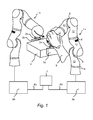
- FIG. 1 is a first force / torque-controlled manipulator 1a and a second force / torque-controlled manipulator 1b shown.
- it is in the illustrated manipulators 1a and 1b to lightweight robot of the type KUKA LBR III.
- Each manipulator 1 a and 1 b has an end effector 3 on its hand flange 2 a, 2 b.
- the end effector 3 may also be referred to as a gripper.
- the manipulator 1a is set up for manually guided movement and carries a first gripper half 3a.
- the second manipulator 1b is automatically activated and carries a second gripper half 3b.
- the manipulators 1a and 1b have members 12 which are connected to each other by joints 8. By moving the joints 8 of the manipulators 1a and 1b, the end effectors 3a and 3b are moved alone or together with a workpiece 4.
- the manually guided manipulator 1a is connected to a first control device 5a.
- the automatically controlled manipulator 1b is connected to a second control device 5b.
- Both control devices 5a, 5b are connected to a common control computer 7, for example a PC, via interface connections 6a and 6b, which may be, for example, (fast-research-interface; FRI) interfaces.
- FRI fast-research-interface
- a control program OROCOS
- the manipulator 1 a In the exemplary embodiment shown, the manipulator 1 a, indicated schematically by the human hand 9, manually guided.
- the control device 5a is set up to operate the manually guided manipulator 1a in at least one of its degrees of freedom and / or torque-controlled and to automatically control a second manipulator 1b as a function of the first force and / or torque-controlled manipulator 1a.
- the control device 5a is set up in the application example to the manipulator 1a in at least one of its degrees of freedom by means of compliance control operate and automatically control the second manipulator 1b in response to the compliance-controlled manipulator 1a.
- the control devices 5a, 5b, 7 are set up to allow the automatically controlled manipulator 1b to perform a movement mirrored to the manually guided manipulator 1a. The movements are executed here in particular at the same time.
- the first manipulator 1a is manually brought to the workpiece 4 by means of the hand 9 of a user.
- the user applies a gripper half 3a of the manipulator 1a to one of two opposite side walls of the workpiece 4.
- the second manipulator 1b with its gripper half 3b moves in mirror symmetry to the opposite side wall of the workpiece 4.
- the workpiece 4 is clamped between the two gripper halves 3a, 3b and can be moved or raised, for example.
- a clamping force may be previously defined, i. be specified.
- known workpieces 4 can be detected by means of at least one force / torque-controlled manipulator 1a, that the current distance corresponds, for example, the two gripper halves 3a and 3b of the workpiece width and then the at least two manipulators 1a and 1b are driven, a force from the workpiece 4th exercise.
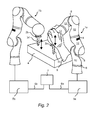
- FIG. 2 another example of application is shown.
- the manually guided manipulator 1a is locked by the control devices 5a in the three spatial rotations and can only perform translational movements. This ensures the tool handled by the manipulator 1a, for example a drill 3c, always impinges perpendicular to the flat workpiece 4.
- the manipulator 1a can be moved manually to the desired location for the bore of the workpiece 4 by means of a hand 9 of the user translational.
- the automatically controlled manipulator 1b moves its drill 3d to a second location of the workpiece 4 in order to automatically introduce a bore, which is symmetrical to the first bore, into the workpiece 4.
- the automatically controlled manipulator 1b requires no limitation of its degrees of freedom, for example, no limitation or blocking of its rotations, since by blocking the rotations of the manually guided manipulator 1a, the automatically controlled manipulator 1b can not perform any rotations. Consequently, the second bore made by the drill 3d has the same quality as the first bore of the first drill 3c.
- FIG. 3 an embodiment of a method according to the invention is shown schematically.
- a manually guided movement of at least one first manipulator (1a) takes place in at least one of its degrees of freedom.
- the manual approach can, according to a method step S3, be a feeding of a tool, in particular a gripper or a gripper half, held by the at least one manipulator (1a, 1b) to the workpiece.
- a second method step S2 an automatic control of at least one second manipulator (1b) takes place as a function of the manually guided manipulator.
- the automatic In accordance with a method step S4, it is possible to bring it into line with a further tool held by the at least one further manipulator (1b), in particular another gripper or a further gripper half (3a, 3b).
- a third method step S6 the workpiece (4) is clamped between one gripper half (3a) of the manually guided manipulator (1a) and the other gripper half (3b) of the automatically controlled further manipulator (1b).
- a fourth method step S5 a common processing and / or movement of the same workpiece (4) by the cooperating manipulators (1a, 1b) can take place by manually guiding at least one of the manipulators (1a, 1b) and / or the workpiece (4).
Abstract
Description
Die Erfindung betrifft ein Werkstück-Handhabungssystem, aufweisend mindestens zwei zur Handhabung von Werkstücken kooperierende Manipulatoren, die mittels wenigstens einer frei programmierbaren Steuervorrichtung in drei oder mehr Achsen automatisch steuerbar und/oder programmierbar sind. Die Erfindung betrifft auch ein Verfahren zum Manipulieren von Werkstücken mittels kooperierender Manipulatoren, die von wenigstens einer Steuervorrichtung gesteuert sind, insbesondere mittels eines erfindungsgemäßen Werkstück-Handhabungssystems.The invention relates to a workpiece handling system, comprising at least two manipulators cooperating for handling workpieces, which are automatically controllable and / or programmable by means of at least one freely programmable control device in three or more axes. The invention also relates to a method for manipulating workpieces by means of cooperating manipulators, which are controlled by at least one control device, in particular by means of a workpiece handling system according to the invention.
Aus der
Aufgabe der Erfindung ist es, ein Werkstück-Handhabungssystem zu schaffen und ein Verfahren bereitzustellen, das eine intuitive Handhabung von Werkstücken durch kooperierende Manipulatoren ermöglicht.The object of the invention is to provide a workpiece handling system and to provide a method which allows an intuitive handling of workpieces by cooperating manipulators.
Diese Aufgabe wird erfindungsgemäß gelöst durch ein Werkstück-Handhabungssystem, aufweisend mindestens zwei zur Handhabung von Werkstücken kooperierende Manipulatoren, die mittels wenigstens einer frei programmierbaren Steuervorrichtung in drei oder mehr Achsen automatisch steuerbar und/oder programmierbar sind, wobei mindestens ein erster Manipulator in wenigstens einem seiner Freiheitsgrade zum manuell geführten Bewegen eingerichtet ist, und die Steuervorrichtung eingerichtet ist, mindestens einen zweiten Manipulator in Abhängigkeit des manuell geführten Manipulators automatisch zu steuern.This object is achieved by a workpiece handling system, comprising at least two manipulators cooperating for handling workpieces, which are automatically controllable and / or programmable by means of at least one freely programmable control device in three or more axes, wherein at least one first manipulator in at least one of his Degree of freedom is set up for manually guided movement, and the control device is set up to automatically control at least one second manipulator in dependence on the manually guided manipulator.
Das Werkstück-Handhabungssystem kann zum Positionieren bzw. zum Transportieren beispielsweise schwerer Werkstücke, alternativ oder ergänzend zur Montage und/oder Bearbeitung des Werkstücks dienen. Statt eines einzelnen Werkstücks, das durch die mindestens zwei kooperierenden Manipulatoren gleichzeitig bearbeitet bzw. gehandhabt wird, können auch mehrere Werkstücke gleichzeitig durch die mindestens zwei kooperierenden Manipulatoren bearbeitet bzw. gehandhabt werden, insbesondere jeweils ein Werkstück durch jeweils einen Manipulator bearbeitet bzw. gehandhabt werden, wobei mehrere Werkstücke auch von jeweils einem Manipulator in synchronisierten Bewegungen bearbeitet bzw. gehandhabt werden können.The workpiece handling system can be used for positioning or transporting, for example, heavy workpieces, alternatively or additionally to the assembly and / or machining of the workpiece. Instead of a single workpiece, which is processed or handled simultaneously by the at least two cooperating manipulators, a plurality of workpieces can also be machined or handled simultaneously by the at least two cooperating manipulators, in particular in each case a workpiece can be processed or handled by a respective manipulator. wherein several workpieces can also be edited or handled by a manipulator in synchronized movements.
Die kooperierenden Manipulatoren sind Teil eines gemeinsamen Handhabungssystems, so dass die kooperierenden Manipulatoren sich auch einen gemeinsamen Arbeitsraum teilen können. Von den kooperierenden Manipulatoren kann jeder Manipulator mit einer separaten Steuerungsvorrichtung verbunden sein. Die mehreren Steuerungsvorrichtungen können beispielsweise mittels Schnittstellen und über Datenleitungen verbunden bzw. synchronisiert sein. Die kooperierenden Manipulatoren können jedoch alternativ auch durch eine gemeinsame Steuerungsvorrichtung betrieben werden. Die gemeinsame Steuerungsvorrichtung bzw. die mehreren separaten Steuerungsvorrichtungen können zusätzlich durch eine übergeordnete bzw. nebengeordnete weitere Steuerungseinrichtung überwacht bzw. für eine kooperierende Zusammenarbeit aufeinander abgestimmt werden.The cooperating manipulators are part of a common handling system, so that the cooperating manipulators can also share a common workspace. Of the cooperating manipulators each manipulator can be connected to a separate control device. The plurality of control devices may, for example, be connected and / or synchronized by means of interfaces and data lines. However, the cooperating manipulators can alternatively also be operated by a common control device. The common control device In addition, the plurality of separate control devices can additionally be monitored by a higher-level or secondary control device or coordinated with one another for co-operating cooperation.
Der erste Manipulator kann in allen Freiheitsgraden d.h. beispielsweise kartesisch in den drei Raumrichtungen und drei Rotationen oder beispielsweise achsbezogen gemäß seiner Gelenke manuell geführt bewegt werden. Alternativ kann der erste Manipulator in weniger Freiheitsgraden, beispielsweise auch nur einem einzigen Freiheitsgrad beispielsweise in einer kartesischen Raumrichtungen oder einer Raumrotation oder bezüglich eines Gelenks manuell geführt bewegt werden. So kann beispielsweise zugelassen sein, dass der erste Manipulator hinsichtlich seines Flansches oder eines Werkzeugbezugspunktes (Tool-Center-Point) nur in den kartesischen Raumrichtungen manuell geführt bewegt werden kann, wo hingegen eine Drehung, wie beispielsweise ein Kippen im kartesischen Raum gesperrt ist d.h. der Flansch oder der Werkzeugbezugspunkt nicht manuell gekippt oder gedreht werden kann. Eine solche Sperrung von Freiheitsgraden für das manuelle Bewegen muss dabei lediglich für den einen, manuell zu bewegenden Manipulator vorgesehen sein, wo hingegen der zweite, automatisch in Abhängigkeit des manuell geführten Manipulators gesteuerte Manipulator keine diesbezügliche Sperrung von Freiheitsgraden benötigt.The first manipulator can be used in all degrees of freedom, i. for example, Cartesian in the three spatial directions and three rotations or, for example, axially related to his joints are moved manually guided. Alternatively, the first manipulator can be moved manually in less degrees of freedom, for example also only a single degree of freedom, for example in a Cartesian spatial direction or a spatial rotation or with respect to a joint. Thus, for example, it may be permitted that the first manipulator can be moved manually in terms of its flange or a tool reference point only in the Cartesian spatial directions, whereas rotation, such as tilting in Cartesian space, is blocked. the flange or tool reference point can not be manually tilted or rotated. Such blocking of degrees of freedom for manual movement must be provided only for the one, manually manipulator to be manipulated, whereas, on the other hand, the second manipulator, which is automatically controlled as a function of the manually guided manipulator, does not require blocking of degrees of freedom in this respect.
Der zweite, automatisch in Abhängigkeit des manuell geführten Manipulators gesteuerte Manipulator kann die Bewegung des manuell geführten Manipulators einfach kopieren d.h. die selbe Bewegung synchron durchführen. Alternativ kann der automatisch gesteuerte Manipulator eine im geometrischen Sinne nicht-kongruente d.h. ähnliche Bewegung synchron ausführen. Insoweit kann der automatisch gesteuerte Manipulator eine Bewegung des manuell geführten Manipulators unter einem anderen Maßstab kopiert durchführen. Die Bewegung des automatisch gesteuerten Manipulators kann in Abhängigkeit des Anwendungsfalls statt synchron d.h. zeitgleich auch zeitlich versetzt später durchgeführt werden.The second manipulator, which is automatically controlled as a function of the manually guided manipulator, can simply copy the movement of the manually guided manipulator, ie perform the same movement synchronously. Alternatively, the automatically controlled manipulator synchronously perform a non-congruent in the geometrical sense ie similar movement. In that regard, the automatically controlled manipulator may move the manually guided manipulator under another Copy the scale. The movement of the automatically controlled manipulator can be carried out later depending on the application instead of synchronously ie at the same time.
Die Steuervorrichtung kann eingerichtet sein, den manuell geführten Manipulator in mindestens einem seiner Freiheitsgrade kraft- und/oder momentengeregelt zu betreiben und einen weiteren Manipulator in Abhängigkeit des kraft- und/oder momentengeregelten Manipulators automatisch zu steuern.The control device can be set up to operate the manually guided manipulator in at least one of its degrees of freedom and / or torque-controlled and to automatically control another manipulator as a function of the force- and / or torque-controlled manipulator.
Der manuell geführte Manipulator wird in diesem Fall nicht rein passiv d.h. antriebslos durch einen Benutzer weggedrückt. Statt dessen kann im kraft- und/oder momentengeregelten Betrieb eine vom Benutzer auf den Manipulator aufgebrachte Kraft eine Regelgröße zum automatischen Steuern bzw. Regeln der Position des manuell geführten Manipulators bilden. es kann auch ein haptisches Feedback an den geführten Manipulator zurückgegeben werden. Die Kraft, die der Benutzer dabei fühlt, kann in Abhängigkeit des Prozessstatus bestimmt sein.The manually guided manipulator will not be purely passive in this case. de-energized pushed by a user. Instead, in force and / or torque-controlled operation, a force applied by the user to the manipulator can form a controlled variable for automatically controlling or regulating the position of the manually guided manipulator. Haptic feedback can also be returned to the guided manipulator. The force that the user feels can be determined depending on the process status.
Die Steuervorrichtung kann eingerichtet sein, einen der Manipulatoren in mindestens einem seiner Freiheitsgrade mittels Nachgiebigkeitsregelung zu betreiben und einen weiteren Manipulator in Abhängigkeit des nachgiebigkeitsgeregelten Manipulators automatisch zu steuern.The control device can be set up to operate one of the manipulators in at least one of its degrees of freedom by means of compliance control and to automatically control another manipulator as a function of the compliance-controlled manipulator.
Eine Nachgiebigkeit d.h. Nachgiebigkeitsregelung des Manipulators kann insbesondere mittels einer Impedanzregelung oder einer Admittanzregelung erreicht werden.A compliance, i. Compliance control of the manipulator can be achieved in particular by means of an impedance control or an admittance control.
Die Steuervorrichtung kann eingerichtet sein, die Nachgiebigkeit des Manipulators mittels Impedanzregelung zu erzeugen.The control device may be configured to generate the compliance of the manipulator by means of impedance regulation.
Eine Impedanzregelung basiert im Gegensatz zur Admittanzregelung auf einer vorhandenen Drehmomentenregelung auf Gelenkebene. Es werden die Abweichung der tatsächlichen Lage von einer definierten Solllage gemessen und entsprechend des gewünschten dynamischen Verhaltens eine gewünschte verallgemeinerte Kraft, bzw. Kräfte und Momente, bestimmt. Diese Kraft kann über die bekannte Kinematik des Manipulators auf entsprechende Gelenkdrehmomente abgebildet werden. Die Drehmomente können schließlich über die unterlagerte Drehmomentenregelung eingestellt werden.An impedance control is based on an existing torque control at the joint level, in contrast to the admittance control. The deviation of the actual position from a defined desired position is measured, and a desired generalized force or forces and moments are determined according to the desired dynamic behavior. This force can be mapped via the known kinematics of the manipulator to corresponding joint torques. The torques can finally be adjusted via the subordinate torque control.
Die Steuervorrichtung kann eingerichtet sein, die Nachgiebigkeit des Manipulators mittels Admittanzregelung zu erzeugen.The control device may be configured to generate the flexibility of the manipulator by means of admittance control.
Eine Admittanzregelung basiert auf einer vorhandenen Positionsregelung des Manipulators auf Gelenkebene. Hier müssen die von außen auf den Manipulator einwirkenden verallgemeinerten Kräften gemessen werden. Ausgehend von diesen Kräften wird eine, dem gewünschten dynamischen Verhalten entsprechende, Bewegung des Manipulators bestimmt, die über eine inverse Kinematik und die unterlagerte Positionsregelung an den Manipulator kommandiert wird.An admittance control is based on an existing position control of the manipulator at the joint level. Here, the generalized forces acting on the manipulator from the outside must be measured. On the basis of these forces, a movement of the manipulator corresponding to the desired dynamic behavior is determined, which is commanded by an inverse kinematics and the subordinate position control to the manipulator.
Die Erzielung eines gewünschten kartesischen Verhaltens kann basierend auf einer unterlagerten Positions-, Drehmomenten- oder Gelenk-Impedanzregelung erfolgen. Die Realisierung dieser Regelungen können durch die Integration von Momentensensorik in die Gelenke eines Industrieroboters erreicht werden. Der Sensor erfasst dabei das am Abtrieb eines Getriebes wirkende eindimensionale Drehmoment. Diese Größe kann für die Regelung als Messgröße herangezogen werden und ermöglicht somit die Berücksichtigung der Elastizität der Gelenke im Rahmen der Regelung. Insbesondere werden durch eine Drehmomentsensorik, im Gegensatz zur Verwendung eines Kraftmomentensensors an einem Endeffektor des Manipulators, auch diejenigen Kräfte gemessen, die nicht auf den Endeffektor, sondern auf die Glieder des Manipulators und/oder insbesondere auf ein von dem Manipulator gehaltenes Werkstück ausgeübt werden.The achievement of a desired Cartesian behavior can be done based on a subordinate position, torque or joint impedance control. The realization of these regulations can be achieved by integrating torque sensors into the joints of an industrial robot. The sensor detects the one-dimensional torque acting on the output of a gearbox. This variable can be used for the control as a measured variable and thus allows the consideration of the elasticity of the joints in the context of the scheme. In particular, by a torque sensor, in contrast to the use of a force torque sensor on an end effector of the manipulator, those forces are measured, not on the end effector, but on the members of the manipulator and / or in particular on a held by the manipulator workpiece are exercised.
Die Steuervorrichtung kann eingerichtet sein, den mindestens einen automatisch gesteuerten Manipulator eine zu dem manuell geführten Manipulator gleichförmige, insbesondere kongruente oder ähnliche Bewegung ausführen zu lassen.The control device can be set up to let the at least one automatically controlled manipulator execute a movement which is uniform, in particular congruent or similar, to the manually guided manipulator.
Der mindestens eine automatisch gesteuerte Manipulator kann auch eine völlig andere Bewegung als der manuell geführte Manipulator durchführen, wobei die verschiedenen Bewegungen lediglich zeitlich gekoppelt sind. Alternativ kann jedoch der automatisch gesteuerte Manipulator eine gleichförmige Bewegung ausführen, d.h. der Bewegungspfad des automatisch gesteuerten Manipulators weist im geometrischen Sinne dieselbe Form auf, ohne jedoch gleiche Größe und Orientierung aufweisen zu müssen. Im speziellen Fall einer kongruenten Bewegung fährt der automatisch gesteuerte Manipulator einen Bewegungspfad ab, der im geometrischen Sinne lediglich durch Drehung, Verschiebung, Spiegelung oder einer beliebigen Kombination dieser Abbildungen aus dem vom manuell geführten Manipulator gefahrenen Bewegungspfad entsteht. Bei einer ähnlichen Abbildung fährt der mindestens eine automatisch gesteuerte Manipulator eine vergrößerte oder verkleinerte Abbildung aus dem vom manuell geführten Manipulator gefahrenen Bewegungspfad ab. So kann beispielsweise der manuell geführte Manipulator einen Bewegungspfad bezüglich eines verkleinerten Modells des Werkstücks vorgeben und der mindestens eine automatisch gesteuerte Manipulator kann diesen Bewegungspfad auf einem oder auf mehreren größeren Werkstücken abfahren.The at least one automatically controlled manipulator can also perform a completely different movement than the manually guided manipulator, the various movements are only temporally coupled. Alternatively, however, the automatically controlled manipulator may perform a uniform motion, i. the movement path of the automatically controlled manipulator has the same shape in the geometric sense, but without having to have the same size and orientation. In the specific case of a congruent movement, the automatically controlled manipulator moves off a path of movement which, in the geometrical sense, arises only through rotation, displacement, reflection or any combination of these images from the motion path traveled by the manually guided manipulator. In a similar illustration, the at least one automatically controlled manipulator departs an enlarged or reduced image from the motion path traveled by the manually guided manipulator. Thus, for example, the manually guided manipulator can specify a movement path with respect to a reduced model of the workpiece and the at least one automatically controlled manipulator can travel this movement path on one or more larger workpieces.
Die Steuervorrichtung kann eingerichtet sein, den automatisch gesteuerten Manipulator eine zu dem manuell geführten Manipulator gespiegelte Bewegung ausführen zu lassen. Dies ist beispielsweise dann zweckmäßig, wenn ein symmetrisches Werkstück von zwei gegenüberliegenden Seiten in gleicher Weise bearbeitet und/oder gehandhabt werden sollen. Beispielsweise wenn an zwei gegenüberliegenden Seiten zwei identische Bohrungen angebracht werden sollen, oder das Werkstück beispielsweise mittels zweier Greiferhälften, von denen jeweils eine Greiferhälfte von jeweils einem Manipulator geführt wird, an den beiden gegenüberliegenden Seiten gegriffen, insbesondere einklemmend gegriffen werden soll. Dabei kann der manuell geführte Manipulator mit seiner Greiferhälfte durch einen Benutzer lediglich mit geringer Kraft an eine Seite des Werkstücks herangeführt und angedrückt werden. Der automatisch gesteuerte Manipulator folgt dieser Bewegung des manuell geführten Manipulators synchron und insbesondere gespiegelt, wodurch die Greiferhälfte des automatisch gesteuerten Manipulators an einer gegenüberliegenden Seite des Werkstücks mit gleicher Kraft herangeführt und angedrückt wird, wie durch den Benutzer auf der anderen Seite vorgegeben. Bei verformbaren bzw. elastischen Werkstücken kann sich die Klemmkraft aus der Anpresskraft, die durch den Benutzer in den manuell geführten Manipulator bzw. in das Werkstück eingeleitet wird, bestimmen. Die Klammkraft kann auch durch Messung mittels eines oder mehrerer zusätzlicher Kraftsensoren, die beispielsweise an den Greiferhälten vorgesehen sind, bestimmt werden.The control device can be set up to let the automatically controlled manipulator perform a movement mirrored to the manually guided manipulator. This is for example then useful if a symmetrical workpiece to be processed and / or handled in the same way from two opposite sides. For example, if two identical holes to be mounted on two opposite sides, or the workpiece, for example by means of two gripper halves, each of which a gripper half is guided by a respective manipulator, gripped on the two opposite sides to be gripped in particular clamping. In this case, the manually guided manipulator can be brought with his gripper half by a user only with little force to one side of the workpiece and pressed. The automatically controlled manipulator follows this movement of the manually guided manipulator synchronously and in particular mirrored, whereby the gripper half of the automatically controlled manipulator on an opposite side of the workpiece with the same force is introduced and pressed, as predetermined by the user on the other side. In deformable or elastic workpieces, the clamping force from the contact pressure, which is initiated by the user in the manually guided manipulator or in the workpiece, determine. The clamping force can also be determined by measuring by means of one or more additional force sensors, which are provided for example on the gripper hammers.
In einer alternativen Ausführung kann der Benutzer den manuell geführten Manipulator mit seiner Greiferhälfte mit geringer Kraft an eine Seite des Werkstücks bis zu einer Berührung heranführen und gar nicht oder nur unwesentlich andrücken. Die aufzubringende Klemmkraft kann vorgegeben sein und von dem automatisch gesteuerten Manipulator und dem manuell geführten Manipulator anschließend automatisch andrückend auf das Werkstück aufgebracht werden.In an alternative embodiment, the user can bring the manually guided manipulator with its gripper half with little force to one side of the workpiece to a touch and not or only slightly press. The applied clamping force can be predetermined and then applied by the automatically controlled manipulator and the manually guided manipulator automatically pressing the workpiece.
Anstatt das Werkstück mittels zweier Manipulatoren zwischen zwei Greiferhälften zu klemmen, kann auch jeder Manipulator einen vollständigen Greifer aufweisen und das Werkstück an zwei verschiedenen, insbesondere gegenüberliegenden Stellen des Werkstücks, insbesondere formschlüssig gegriffen werden. So kann beispielsweise ein Benutzer den Greifer des manuell geführten Manipulators an einen Griffabschnitt des Werkstücks führen und der automatisch gesteuerte Manipulator greift zeitgleich in einer synchronen Bewegung oder zeitversetzt später das Werkstück auf der gegenüberliegenden Seite in gleicher Weise, so dass das Werkstück die Last teilend von beiden Manipulatoren aufgenommen werden kann.Instead of clamping the workpiece by means of two manipulators between two gripper halves, each manipulator can have a complete gripper and the workpiece at two different, in particular opposite points of the workpiece, in particular positively engaged. For example, a user may guide the gripper of the manually guided manipulator to a grip portion of the workpiece, and the automatically controlled manipulator simultaneously engages the workpiece on the opposite side in a synchronous movement or delayed in a similar manner, such that the workpiece divides the load from both Manipulators can be included.
Die Steuervorrichtung kann eingerichtet sein, die Bewegungen der automatisch gesteuerten Manipulatoren und des manuell geführten Manipulators zeitgleich auszuführen. Dies kann in Fällen sinnvoll sein, in denen ein einzelnes Werkstück von wenigstens zwei Manipulatoren gemeinsam gehandhabt werden soll. Dies kann beispielsweise der Fall sein, wenn die Last des Werkstücks teilend getragen werden soll oder eine Stabilitätsanforderung erfüllt werden soll, wie beispielsweise ein Halten des Werkstücks in der Horizontalen durch die Manipulatoren. Aufgrund des manuell führbaren Manipulators kann das von den wenigstens zwei Manipulatoren getragene Werkstück auch durch manuelles Drücken oder Ziehen des Werkstücks bewegt werden. Dabei wird die Kraft, die ein Benutzer auf das Werkstück ausübt auf den manuell führbaren Manipulator übertragen, so dass der manuell führbare Manipulator sich entsprechend bewegt und der wenigstens eine automatisch gesteuerte Manipulator die Bewegung mitmacht, so dass das Werkstück von den Manipulatoren aktiv bewegt wird.The control device can be set up to execute the movements of the automatically controlled manipulators and of the manually guided manipulator at the same time. This may be useful in cases where a single workpiece is to be handled jointly by at least two manipulators. This may be the case, for example, when the load of the workpiece is to be carried divisionally or a stability requirement is to be met, such as holding the workpiece in the horizontal by the manipulators. Due to the manually operable manipulator, the workpiece carried by the at least two manipulators can also be moved by manually pressing or pulling the workpiece. In this case, the force exerted by a user on the workpiece is transferred to the manually manageable manipulator, so that the manually maneuverable manipulator moves accordingly and the at least one automatically controlled manipulator makes the movement, so that the workpiece is actively moved by the manipulators.
Statt eines derartigen Master-/Slave-Betriebs können auch beide Manipulatoren in einen nachgiebigen Modus geschalten werden. Beide Manipulatoren zielen dabei auf einen Punkt in dem Werkstück und bringen sozusagen eine gewisse Federkraft auf. Dabei ist dann keiner der Manipulatoren im Slave-Betrieb.Instead of such a master / slave operation both manipulators can be switched into a compliant mode. Both manipulators aim for a point in the workpiece and bring up a certain spring force, so to speak. In this case, none of the manipulators is in slave mode.
So kann beispielsweise ein sehr schweres Werkstück, das mittels der Manipulatoren sozusagen "in der Schwebe" gehalten wird, mit geringem Kraftaufwand beispielsweise mit einer Hand oder sogar nur mittels eines Fingers des Benutzers angehoben bzw. abgesenkt oder in einer horizontalen Richtung verschoben werden.Thus, for example, a very heavy workpiece, which is kept "suspended" by means of the manipulators, can be raised or lowered or moved in a horizontal direction with little effort, for example with one hand or even only by a user's finger.
Die Steuervorrichtung kann jedoch alternativ auch eingerichtet sein, die Bewegungen des automatisch gesteuerten Manipulators zu einer späteren Zeit bzw. zeitversetzt auszuführen.Alternatively, however, the control device can also be set up to execute the movements of the automatically controlled manipulator at a later time or with a time delay.
Ein erfindungsgemäßes Verfahren zum Manipulieren von Werkstücken mittels kooperierender Manipulatoren, die von wenigstens einer Steuervorrichtung gesteuert sind, insbesondere mittels eines beschriebenen erfindungsgemäßen Werkstück-Handhabungssystems, kann die folgenden Schritte aufweisen:
- manuell geführtes Bewegen mindestens eines der Manipulatoren in wenigstens einem seiner Freiheitsgrade und
- automatisches Steuern mindestens eines weiteren Manipulators in Abhängigkeit des manuell geführten Manipulators.
- manually guided moving at least one of the manipulators in at least one of its degrees of freedom and
- automatic control of at least one further manipulator as a function of the manually guided manipulator.
Das Verfahren kann die weiteren Schritte aufweisen:
- manuelles Heranführen eines von dem mindestens einen Manipulator gehaltenen Werkzeugs, insbesondere Greifers oder einer Greiferhälfte, an das Werkstück;
- automatisches Heranführen eines von dem mindestens einen weiteren Manipulator gehaltenen weiteren Werkzeugs, insbesondere weiteren Greifers oder einer weiteren Greiferhälfte, an das Werkstück.
- manually bringing one of the at least one manipulator held tool, in particular gripper or a gripper half, to the workpiece;
- automatic introduction of a further tool held by the at least one further manipulator, in particular another gripper or a further gripper half, to the workpiece.
In einer Ausführungsformen kann das Verfahren den weiteren Schritt aufweisen:
- gemeinsames Bearbeiten und/oder Bewegen desselben Werkstücks durch die kooperierenden Manipulatoren mittels manuellen Führens wenigstens einer der Manipulatoren und/oder des Werkstücks.
- cooperatively processing and / or moving the same workpiece by the cooperating manipulators by manually guiding at least one of the manipulators and / or the workpiece.
Insbesondere kann das Verfahren den weiteren Schritt aufweisen:
- Einklemmen des Werkstücks zwischen der einen Greiferhälfte des manuell geführten Manipulators und der anderen Greiferhälfte des automatisch gesteuerten, weiteren Manipulators.
- Clamp the workpiece between the one gripper half of the manually guided manipulator and the other gripper half of the automatically controlled further manipulator.
In einer alternativen Ausführungsform kann das Verfahren den weiteren Schritt aufweisen:
- paralleles Bearbeiten und/oder Bewegen verschiedener Werkstücke durch jeweils einen der kooperierenden Manipulatoren.
- parallel processing and / or moving of different workpieces by one of the cooperating manipulators.
In einer weiteren Ausführungsform kann, alternativ oder ergänzend zu einem der beschriebenen Verfahren, das Verfahren den weiteren Schritt aufweisen:
- Beschränken wenigstens eines Freiheitsgrades mindestens eines der kooperierenden Manipulatoren Zusammenfassend und mit anderen Worten beschrieben betrifft die Erfindung ein Werkstück-Handhabungssystem, aufweisend mindestens zwei zur Handhabung von Werkstücken kooperierende Manipulatoren d.h. Roboter, die neben dem Manipulator, beispielsweise einem Roboterarm auch eine Steuerungsvorrichtung umfassen. Bedeutend ist, dass mehrere Roboter zusammen verwendet werden. Mindestens einer dieser Roboter kann per Hand geführt werden. Wenn man einen kraft-/momentengeregelten Roboter verwendet, hat das den Vorteil, dass diese Führen sehr dynamisch sein kann. Dieser handgeführte Roboter wird als Eingabegerät verwendet und die anderen Roboter kopieren oder spiegeln dessen Bewegungen.
- Restricting at least one degree of freedom of at least one of the cooperating manipulators In summary, and described in other words, the invention relates to a workpiece handling system, comprising at least two manipulators cooperating for handling workpieces, ie robots which, in addition to the manipulator, for example a robot arm, also comprise a control device. It is important that several robots are used together. At least one of these robots can be guided by hand. Using a force / torque controlled robot has the advantage that these guides can be very dynamic. This handheld robot is used as an input device and the other robots copy or mirror its movements.
In einer konkreten Ausführung werden beispielsweise zwei kraft-/momentengeregelte Roboter mit zwei Steuerungsvorrichtungen betrieben. In einer alternativen Ausführung kann auch nur der manuell geführte Roboter kraft-/momentengeregelt betrieben werden und der zweite bzw. weitere Roboter können positionsgesteuert betrieben werden. Die Steuerungen können beispielsweise über eine Schnittstelle mit einem Steuerrechner, beispielsweise ein PC, verbunden sein, auf dem ein Roboterbetriebsprogramm installiert ist. Die beiden Roboter können mit internen Momentensensoren ausgestattet sein und mittels wenigstens einer Robotersteuerung kooperierend betrieben werden.In a concrete embodiment, for example, two force / torque controlled robots are operated with two control devices. In an alternative embodiment, only the manually guided robot can be operated under force / torque control, and the second or further robot can be operated position-controlled. The controls may be connected, for example, via an interface to a control computer, for example a PC, on which a robot operating program is installed. The two robots can be equipped with internal torque sensors and operated cooperatively by means of at least one robot controller.
Bei dieser Ausführung kann folgender, beispielhafter Ablauf realisiert werden:
- I n einer ersten Phase führ der Benutzer den einen kraft-/momentengeregelten Roboter frei durch den Arbeitsraum zum Werkstück.
- In a first phase, the user freely guides the one force / torque controlled robot through the working space to the workpiece.
In einer zweiten Phase teilt der Benutzer dem System mit, dass die Orientierung des ersten kraft-/momentengeregelten Roboters nun stimmt. Dies kann er beispielsweise tun indem er ein Eingabemittel betätigt, beispielsweise einen elektrischen Schalter oder eine Taste drückt, oder indem er den anderen Roboter antippt d.h. eine Kraft in die Struktur des kraft-/momentengeregelten Roboters einleitet, die von der Steuerungsvorrichtung mittels der Kraft-/Momentensensorik erkannt und dann ausgewertet werden kann.In a second phase, the user informs the system that the orientation of the first force / torque controlled robot is now correct. He can do this by, for example actuates an input means, for example presses an electrical switch or a button, or by tapping the other robot, that is a force in the structure of the force / torque controlled robot initiates, which can be detected by the control device by the force / moment sensor and then evaluated ,
In einer dritten Phase fährt der zweite kraft-/momentengeregelte Roboter von der anderen Seite an das Werkstück heran. Dabei kann die Größe des Werkstücks bekannt sein. Beispielsweise durch eine Impedanzregelung ist es möglich kleinere Orientierungsfehler auszugleichen. Beide Roboter nehmen anschließend das Werkstück auf, indem sie es zwischen sich einklemmen oder mit Greifern, beispielsweise Haken, aufnehmen.In a third phase, the second force / torque controlled robot approaches the workpiece from the other side. In this case, the size of the workpiece can be known. For example, by an impedance control, it is possible to compensate for minor orientation errors. Both robots then pick up the workpiece by pinching it between them or picking it up with grippers, such as hooks.
In einer vierten Phase kann der Benutzer die Position des Werkstücks ändern, indem er die Roboter im Raum bewegt. Arbeitsraumbegrenzungen sorgen dafür, dass das Werkstück nicht in Positionen gebracht werden kann, in denen einer der Roboter das Werkstück nicht mehr erreichen kann.In a fourth phase, the user can change the position of the workpiece by moving the robots in space. Working space limitations ensure that the workpiece can not be brought into positions in which one of the robots can no longer reach the workpiece.
In einer fünften Phase, wenn die Zielposition erreicht ist, kann der Benutzer den Robotern mitteilen, dass sie das Werkstück wieder loslassen sollen. Dies kann beispielsweise durch eine Geste, wie Tippen an der Roboterstruktur, oder durch auseinander Ziehen der Roboter oder durch Betätigen eines Eingabemittels, wie beispielsweise eines elektrischen Schalters, geschehen.In a fifth phase, when the target position is reached, the user can tell the robots to release the workpiece. This can be done for example by a gesture, such as tapping on the robot structure, or by pulling apart the robot or by operating an input means, such as an electric switch.
Gegenüber dem Stand der Technik hat die Erfindung deutliche Vorteile. Generell können Roboter entweder ferngesteuert werden, z.B. über eine 6-D Maus oder über mehrere Steuerknüppel, oder über Kraftmomentensensoren, die üblicher Weise am Flansch vorgesehen sind, im Raum bewegt werden. Roboter auf diese Art und Weise zu bewegen ist jedoch umständlich und langsam. Vorteilhafter ist ein kraft-/momentengeregelter Roboter, welcher durch die integrierte Kraftmomentensensorik und dazugehörigen Modelle frei im Raum bewegt werden kann. Hierbei kann der Roboter auch an seiner Struktur bewegt werden.Compared with the prior art, the invention has significant advantages. In general, robots can either be remotely controlled, eg via a 6-D mouse or several control sticks, or via force torque sensors, which are usually provided on the flange, are moved in space. However, moving robots in this way is cumbersome and slowly. More advantageous is a force- / torque-controlled robot, which can be moved freely in space by the integrated force torque sensor and associated models. In this case, the robot can also be moved on its structure.
Bei kooperierenden Robotern können zwei oder mehr Roboter zusammen an einer Aufgabe arbeiten und ihre Bewegungen im Raum koordinieren. Es ist ohne Weiteres möglich, ein Werkstück auf diese Weise mit mehreren Robotern auf einer programmierten Bahn im Raum zu bewegen. Es ist ebenfalls möglich, dies mit einer der beschriebenen Führungsmethoden zu kombinieren.With cooperating robots, two or more robots can work together on one task and coordinate their movements in space. It is easily possible to move a workpiece in this way with several robots on a programmed path in space. It is also possible to combine this with one of the described guiding methods.
Erfindungsgemäß können zwei oder mehr kraft-/momentengeregelte Roboter gleichzeitig kollaborierend, d.h. in Zusammenarbeit mit dem Menschen und kooperierend, d.h. in-Zusammenarbeit mehrerer Roboter eingesetzt werden. Die Verwendung von kraft-/momentengeregelten Robotern hat den Vorteil, dass eine sehr dynamische Kollaboration möglich ist. Bei dieser Zusammenarbeit werden die sensorischen Fähigkeiten des Menschen mit den Handhabungsfähigkeiten der Maschine verbunden.According to the invention, two or more force / torque controlled robots can collaborate simultaneously, i. in collaboration with humans and cooperating, i. be used in collaboration of multiple robots. The use of force / torque controlled robots has the advantage that a very dynamic collaboration is possible. In this collaboration, the human sensory capabilities are linked to the machine's handling capabilities.
Grundsätzlich können die folgenden Fälle auftreten:
- In einem ersten Fall von gemeinsamer Manipulation von Objekten kann das Werkstück von mehreren Robotern gehalten werden.
- Der Mensch führt das Werkstück dann zur gewünschten Position. Die Roboter sorgen dafür, dass z.B. die Orientierung des Werkstückes stimmt.
- In a first case of joint manipulation of objects, the workpiece can be held by several robots.
- The person then guides the workpiece to the desired position. The robots ensure that, for example, the orientation of the workpiece is correct.
In einem zweiten Fall von gemeinsamer Durchführung eines Prozesses kann das Werkzeug von einem oder mehreren Robotern gehalten werden. Einer dieser Roboter wird von einem Menschen geführt und die anderen kopieren die Bewegungen des ersten Roboters. Ähnlich wie bei der Kopie eines Schlüssels wird der Prozess also an mehreren Stellen identisch durchgeführt.In a second case of joint execution of a process, the tool may be held by one or more robots. One of these robots is led by one person and the others copy the movements of the first one Robot. Similar to the copy of a key, the process is therefore carried out identically in several places.
In einem dritten Fall kann ein Roboter als haptisches Eingabegerät genutzt werden. In diesem Fall stehen die manipulierenden Roboter an einem anderen Ort, als der Roboter, der als Eingabegerät verwendet wird. Den Roboter als Eingabegerät zu verwenden hat den Vorteil, dass die Kinematik des Eingabegerätes genau der des Ausgabegerätes entspricht.In a third case, a robot can be used as a haptic input device. In this case, the manipulating robots are in a different location than the robot used as an input device. Using the robot as an input device has the advantage that the kinematics of the input device corresponds exactly to that of the output device.
Bemerkenswert ist, dass die Roboter erfindungsgemäß in einer Art von Spiegelbetrieb geschalten werden können, um beispielsweise aufeinander zu fahren zu können. Symmetrie- oder Spiegelpunkt werden gewählt, je nach dem wie die Roboter aufgestellt sind und wie man beispielsweise eine Klemmkraft ausüben will. Spiegelbetrieb kann unter Anderem so aussehen, dass der zweite Roboter nur Teile der Sollposition des ersten Roboters, wie Höhe und laterale Position spiegelt, aber nicht die Richtung zwischen den Robotern. Damit bleibt der zweite Roboter erst mal außerhalb des Arbeitsbereichs und kann bei Bedarf in den Arbeitsbereich geholt werden. Diese Aktion kann auch automatisch ausgeübt werden, wenn der geführte Roboter in einen vordefinierten Arbeitsraum eintritt. Der Arbeitsraum wird damit insoweit zur Schaltfläche.It is noteworthy that the robots can be switched according to the invention in a kind of mirror operation, for example, to be able to drive towards each other. Symmetry or mirror point are chosen, depending on how the robots are set up and how, for example, you want to exert a clamping force. Among other things, mirror operation may be such that the second robot only reflects parts of the target position of the first robot, such as height and lateral position, but not the direction between the robots. This leaves the second robot outside the work area and can be brought to the work area if necessary. This action can also be performed automatically when the guided robot enters a predefined working space. The workspace becomes a button to that extent.
Es ist somit möglich auf externe Sensorik verzichten zu können, da der Roboter den manuellen Vorgaben, beispielsweise des Benutzers, folgen kann und dem Benutzer auch haptisches Feedback an das Eingabegerät geben kann. Im ersten Fall führt der Mensch einen der kraft-/momentengeregelten Roboter an das Werkstück. Auf Kommando verwendet der zweite kraft-/momentengeregelte Roboter die Informationen über die Position und Orientierung des ersten kraft-/momentengeregelten Roboters, um ein bekanntes Werkstück von der anderen Seite her anzufahren und dann kooperierend aufzunehmen. Es ist also nicht nötig, die Position eines bekannten Werkstücks durch andere Sensorik zu erfassen. Alternativ kann man jedoch einen oder mehrere Sensoren verwenden, um die Position eines bekannten oder unbekannten Objektes zu bestimmen. In diesem Fall können die Roboter die Position des ersten Roboters um das Objekt herum spiegeln - um so näher man den Objekt kommt, um so mehr nähert sich auch der andere Roboter bzw. nähern sich auch die anderen Roboter an.It is therefore possible to dispense with external sensors, since the robot can follow the manual specifications, for example of the user, and can also give the user haptic feedback to the input device. In the first case, the human performs one of the force / moment controlled robots on the workpiece. On command, the second force / torque controlled robot uses the information about the position and orientation of the first force / torque controlled robot to approach a known workpiece from the other side and then cooperatively record. So it is not necessary to detect the position of a known workpiece by other sensors. Alternatively, however, one may use one or more sensors to determine the position of a known or unknown object. In this case, the robots can mirror the position of the first robot around the object - the closer you get to the object, the closer the other robot approaches or approaches the other robots.
Bei einem kraft-/momentengeregelten Roboter ist es, auch wie bei positionsgesteuerten Robotern, möglich den Arbeitsraum durch virtuelle Wände zu begrenzen. Dies ist in diesem Zusammenhang möglich, da dadurch sichergestellt werden kann, dass das Werkzeug oder Werkstück in einem Bereich bleibt, der von allen Robotern erreicht werden kann. Des Weiteren kann es in vielen Fällen egal sein, welchen der Roboter man als Eingabegerät verwendet.In the case of a force / torque-controlled robot, it is also possible, as with position-controlled robots, to limit the working space through virtual walls. This is possible in this context, since it can be ensured that the tool or workpiece remains in an area that can be reached by all robots. Furthermore, in many cases it may not matter which of the robots one uses as an input device.
Anwendungen für ein erfindungsgemäßes Werkstück-Handhabungssystems sind im Folgenden beispielhaft kurz erwähnt.Applications for a workpiece handling system according to the invention are briefly mentioned below by way of example.
Soll beispielsweise ein sehr breites Werkstück, welches bis unter den Rand mit einer Flüssigkeit gefüllt ist, bewegt werden, dann können die Roboter die Orientierung halten und eventuell sogar die dynamischen Bewegungen der Flüssigkeit, wie beispielsweise Wasser, ausgleichen. Es ist dabei auch möglich sehr heiße, kalte oder aus einem anderen Grund gefährliche oder unangenehme Objekte bzw. Flüssigkeiten zu bewegen.If, for example, a very wide workpiece, which is filled to the brim with a liquid, is moved, then the robots can keep their orientation and possibly even even the dynamic movements of the liquid, such as water, compensate. It is also possible to move very hot, cold or otherwise dangerous or unpleasant objects or liquids.
Soll beispielsweise ein Prozess d.h. ein Arbeitsvorgang mehrfach identisch durchgeführt werden, kann ein Benutzer, beispielsweise ein Schreiner zum Beispiel mehrere Stuhllehnen auf einmal herstellen. Die Handarbeit wird hierbei maschinell unterstützt. Um diesen Effekt zu unterstützten, kann man die Steifigkeit der Roboter über Zeit oder Raum leicht variieren lassen. Dadurch wäre dann jedes Stück ein Unikat.If, for example, a process, ie a work process, is carried out identically several times, a user, for example a carpenter, can, for example, produce several chair backs at once. The manual work is hereby mechanically supported. To support this effect, you can use the Rigidity of the robots can vary slightly over time or space. As a result, each piece would be unique.
Es können andererseits auch Arbeiten in vom Menschen nicht oder nur schwer zu erreichenden Umgebungen oder in gesundheitsgefährlichen Bereichen, wie beispielsweise in chemisch oder bakteriologisch kontaminierten Bereichen mit den erfindungsgemäßen Werkstück-Handhabungssystemen durchgeführt werden.On the other hand, it is also possible to carry out work in environments which are difficult or impossible for humans to reach or in health-endangered areas, for example in chemically or bacteriologically contaminated areas, using the workpiece handling systems according to the invention.
Vorteile und weitere Merkmale eines beispielhaften erfindungsgemäßen Werkstück-Handhabungssystems ergeben sich aus der nachfolgenden Beschreibung einer Ausführung unter Bezugnahme auf die beigefügten Figuren. Konkrete Merkmale dieses Ausführungsbeispiels können allgemeine Merkmale der Erfindung darstellen.Advantages and other features of an exemplary workpiece handling system according to the invention will become apparent from the following description of an embodiment with reference to the accompanying figures. Concrete features of this embodiment may represent general features of the invention.
Es zeigen:
- Fig. 1
- eine perspektivische Ansicht eines WerkstückHandhabungssystems mit kraft-/momentengeregelten Robotern bzw. Manipulatoren in einem ersten Anwendungsbeispiel;
- Fig. 2
- eine perspektivische Ansicht des WerkstückHandhabungssystems mit kraft-/momentengeregelten Robotern bzw. Manipulatoren in einem zweiten Anwendungsbeispiel;
- Fig. 3
- eine schematische Darstellung eines beispielhaften Verfahrensablaufs.
- Fig. 1
- a perspective view of a workpiece handling system with force / torque controlled robots or manipulators in a first application example;
- Fig. 2
- a perspective view of the workpiece handling system with force / torque controlled robots or manipulators in a second application example;
- Fig. 3
- a schematic representation of an exemplary process flow.
In der
Jeder Manipulator 1a und 1b weist an seinem Handflansch 2a, 2b einen Endeffektor 3 auf. Der Endeffektor 3 kann auch als Greifer bezeichnet werden. Im dargestellten Ausführungsbeispiel ist der Manipulator 1a zum manuell geführten bewegen eingerichtet und trägt eine erste Greiferhälfte 3a. Der zweite Manipulator 1b wird automatisch angesteuert und trägt eine zweite Greiferhälfte 3b.Each
Die Manipulatoren 1a und 1b weisen Glieder 12 auf, die durch Gelenke 8 miteinander verbunden sind. Durch Bewegen der Gelenke 8 der Manipulatoren 1a und 1b werden die Endeffektoren 3a und 3b alleine oder gemeinsam mit einem Werkstück 4 bewegt. Der manuell geführte Manipulator 1a ist mit einer ersten Steuervorrichtung 5a verbunden. Der automatisch angesteuert Manipulator 1b ist mit einer zweiten Steuervorrichtung 5b verbunden. Beide Steuervorrichtungen 5a, 5b sind über Schnittstellen-Verbindungen 6a und 6b, die beispielsweise (Fast-Research-Interface; FRI)-Schnittstellen sein können, mit einem gemeinsamen Steuerrechner 7, beispielsweise einem PC, verbunden. Auf dem Steuerrechner 7 kann beispielsweise ein Steuerungsprogramm (OROCOS) installiert sein.The
Im gezeigten Ausführungsbeispiel wird der Manipulator 1a, schematisch durch die menschliche Hand 9 angedeutet, manuell geführt. Die Steuervorrichtung 5a ist dabei eingerichtet, den manuell geführten Manipulator 1a in mindestens einem seiner Freiheitsgrade kraft- und/oder momentengeregelt zu betreiben und einen zweiten Manipulator 1b in Abhängigkeit des ersten kraft- und/oder momentengeregelten Manipulators 1a automatisch zu steuern. Die Steuervorrichtung 5a ist im Anwendungsbeispiel eingerichtet, den Manipulator 1a in mindestens einem seiner Freiheitsgrade mittels Nachgiebigkeitsregelung zu betreiben und den zweiten Manipulator 1b in Abhängigkeit des nachgiebigkeitsgeregelten Manipulators 1a automatisch zu steuern. Dabei sind die Steuervorrichtungen 5a, 5b, 7 eingerichtet, den automatisch gesteuerten Manipulator 1b eine zu dem manuell geführten Manipulator 1a gespiegelte Bewegung ausführen zu lassen. Die Bewegungen werden hier insbesondere zeitgleich ausgeführt.In the exemplary embodiment shown, the
Zunächst wird der erste Manipulator 1a mittels der Hand 9 eines Benutzers manuell an das Werkstück 4 herangeführt. Dabei legt der Benutzer eine Greiferhälfte 3a des Manipulators 1a an eine von zwei gegenüberliegenden Seitenwänden des Werkstücks 4 an. Zeitgleich oder zeitlich später bewegt sich der zweite Manipulator 1b mit seiner Greiferhälfte 3b spiegelsymmetrisch an die gegenüberliegende Seitenwand des Werkstücks 4 heran. Durch Drücken der einen Greiferhälfte 3a des Manipulators 1a gegen die eine Seitenwand des Werkstücks 4 und durch die automatisch gesteuerte Bewegung des zweiten Manipulators 1b wird das Werkstück 4 zwischen den beiden Greiferhälften 3a, 3b eingeklemmt und kann beispielsweise verschoben oder angehoben werden. Eine Klemmkraft kann beispielsweise vorher definiert d.h. vorgegeben werden. Bei bekannten Werkstücken 4 kann mittels des wenigstens einen kraft-/momentengeregelten Manipulators 1a erkannt werden, dass der aktuelle Abstand beispielsweise der beiden Greiferhälften 3a und 3b der Werkstückbreite entspricht und dann die wenigstens zwei Manipulatoren 1a und 1b angesteuert werden, eine Kraft aus das Werkstück 4 auszuüben.First, the
In der
In der
In einem ersten Verfahrensschritt S1 erfolgt ein manuell geführtes Bewegen mindestens eines ersten Manipulators (1a) in wenigstens einem seiner Freiheitsgrade. Das manuelles Heranführen kann gemäß einem Verfahrensschritt S3 ein Heranführen eines von dem mindestens einen Manipulator (1a, 1b) gehaltenen Werkzeugs, insbesondere Greifers oder einer Greiferhälfte, an das Werkstück sein.In a first method step S1, a manually guided movement of at least one first manipulator (1a) takes place in at least one of its degrees of freedom. The manual approach can, according to a method step S3, be a feeding of a tool, in particular a gripper or a gripper half, held by the at least one manipulator (1a, 1b) to the workpiece.
In einem zweiten Verfahrensschritt S2 erfolgt ein automatisches Steuern mindestens eines zweiten Manipulators (1b) in Abhängigkeit des manuell geführten Manipulators. Das automatische Heranführen kann gemäß einem Verfahrensschritt S4 ein Heranführen eines von dem mindestens einen weiteren Manipulator (1b) gehaltenen weiteren Werkzeugs, insbesondere weiteren Greifers oder einer weiteren Greiferhälfte (3a, 3b), an das Werkstück sein.In a second method step S2, an automatic control of at least one second manipulator (1b) takes place as a function of the manually guided manipulator. The automatic In accordance with a method step S4, it is possible to bring it into line with a further tool held by the at least one further manipulator (1b), in particular another gripper or a further gripper half (3a, 3b).
In einem dritten Verfahrensschritt S6 erfolgt ein Einklemmen des Werkstücks (4) zwischen der einen Greiferhälfte (3a) des manuell geführten Manipulators (1a) und der anderen Greiferhälfte (3b) des automatisch gesteuerten, weiteren Manipulators (1b). Anschließend kann in einem vierten Verfahrensschritt S5 ein gemeinsames Bearbeiten und/oder Bewegen desselben Werkstücks (4) durch die kooperierenden Manipulatoren (1a, 1b) mittels manuellen Führens wenigstens einer der Manipulatoren (1a, 1b) und/oder des Werkstücks (4) erfolgen.In a third method step S6, the workpiece (4) is clamped between one gripper half (3a) of the manually guided manipulator (1a) and the other gripper half (3b) of the automatically controlled further manipulator (1b). Subsequently, in a fourth method step S5, a common processing and / or movement of the same workpiece (4) by the cooperating manipulators (1a, 1b) can take place by manually guiding at least one of the manipulators (1a, 1b) and / or the workpiece (4).
Claims (15)
Applications Claiming Priority (1)
| Application Number | Priority Date | Filing Date | Title |
|---|---|---|---|
| DE102010029745A DE102010029745A1 (en) | 2010-06-07 | 2010-06-07 | Workpiece handling system and method for manipulating workpieces by means of cooperating manipulators |
Publications (3)
| Publication Number | Publication Date |
|---|---|
| EP2392435A2 true EP2392435A2 (en) | 2011-12-07 |
| EP2392435A3 EP2392435A3 (en) | 2013-05-01 |
| EP2392435B1 EP2392435B1 (en) | 2020-12-23 |
Family
ID=44834984
Family Applications (1)
| Application Number | Title | Priority Date | Filing Date |
|---|---|---|---|
| EP11168345.4A Active EP2392435B1 (en) | 2010-06-07 | 2011-06-01 | Workpiece handling system and method for manipulating workpieces by means of cooperating manipulators |
Country Status (3)
| Country | Link |
|---|---|
| EP (1) | EP2392435B1 (en) |
| DE (1) | DE102010029745A1 (en) |
| DK (1) | DK2392435T3 (en) |
Cited By (40)
| Publication number | Priority date | Publication date | Assignee | Title |
|---|---|---|---|---|
| EP2664412A3 (en) * | 2012-05-18 | 2015-03-04 | KUKA Systems GmbH | Assembly device and assembly cell |
| DE102013220798A1 (en) | 2013-10-15 | 2015-04-16 | Kuka Laboratories Gmbh | Method for handling objects by means of at least two industrial robots, and associated industrial robots |
| WO2015086722A1 (en) * | 2013-12-13 | 2015-06-18 | Kuka Systems Gmbh | Working apparatus and working method |
| WO2015158612A1 (en) * | 2014-04-15 | 2015-10-22 | Kuka Systems Gmbh | Robot device with a linear axis |
| EP2919085A3 (en) * | 2014-03-11 | 2016-06-29 | KUKA Systems GmbH | Method for operating a robot |
| CN105751197A (en) * | 2016-04-26 | 2016-07-13 | 哈尔滨工程大学 | Auxiliary mechanism for master and slave attitude control and control method |
| WO2016150907A1 (en) * | 2015-03-23 | 2016-09-29 | Kuka Roboter Gmbh | Robust intuitive operating method by touching a manipulator |
| EP3170425A1 (en) * | 2015-11-19 | 2017-05-24 | Khaled A.M.A.A. Al-Khulaifi | Robotic hair dryer holder system with tracking |
| US9713509B2 (en) | 2013-10-24 | 2017-07-25 | Auris Surgical Robotics, Inc. | Instrument device manipulator with back-mounted tool attachment mechanism |
| US9737371B2 (en) * | 2014-09-30 | 2017-08-22 | Auris Surgical Robotics, Inc. | Configurable robotic surgical system with virtual rail and flexible endoscope |
| US9763741B2 (en) | 2013-10-24 | 2017-09-19 | Auris Surgical Robotics, Inc. | System for robotic-assisted endolumenal surgery and related methods |
| US9788910B2 (en) | 2014-07-01 | 2017-10-17 | Auris Surgical Robotics, Inc. | Instrument-mounted tension sensing mechanism for robotically-driven medical instruments |
| US10016900B1 (en) | 2017-10-10 | 2018-07-10 | Auris Health, Inc. | Surgical robotic arm admittance control |
| US10143526B2 (en) | 2015-11-30 | 2018-12-04 | Auris Health, Inc. | Robot-assisted driving systems and methods |
| US10145747B1 (en) | 2017-10-10 | 2018-12-04 | Auris Health, Inc. | Detection of undesirable forces on a surgical robotic arm |
| US10299870B2 (en) | 2017-06-28 | 2019-05-28 | Auris Health, Inc. | Instrument insertion compensation |
| US10314463B2 (en) | 2014-10-24 | 2019-06-11 | Auris Health, Inc. | Automated endoscope calibration |
| US10426559B2 (en) | 2017-06-30 | 2019-10-01 | Auris Health, Inc. | Systems and methods for medical instrument compression compensation |
| CN110582381A (en) * | 2017-04-23 | 2019-12-17 | 富兰卡爱米卡股份有限公司 | apparatus and method for electrical inspection of electrical components |
| US10518405B2 (en) | 2016-06-29 | 2019-12-31 | Abb Schweiz Ag | Industrial robot system comprising a dual arm robot |
| US10583271B2 (en) | 2012-11-28 | 2020-03-10 | Auris Health, Inc. | Method of anchoring pullwire directly articulatable region in catheter |
| US10631949B2 (en) | 2015-09-09 | 2020-04-28 | Auris Health, Inc. | Instrument device manipulator with back-mounted tool attachment mechanism |
| WO2020157185A1 (en) * | 2019-01-30 | 2020-08-06 | Franka Emika Gmbh | Coordination between two cooperative robot manipulators |
| WO2020157187A1 (en) * | 2019-01-31 | 2020-08-06 | Franka Emika Gmbh | Coordination of paths of two robot manipulators |
| WO2020157186A1 (en) * | 2019-01-31 | 2020-08-06 | Franka Emika Gmbh | Teaching process for a robot system consisting of two robot manipulators |
| US10765303B2 (en) | 2018-02-13 | 2020-09-08 | Auris Health, Inc. | System and method for driving medical instrument |
| US10765487B2 (en) | 2018-09-28 | 2020-09-08 | Auris Health, Inc. | Systems and methods for docking medical instruments |
| US10792464B2 (en) | 2014-07-01 | 2020-10-06 | Auris Health, Inc. | Tool and method for using surgical endoscope with spiral lumens |
| US10813539B2 (en) | 2016-09-30 | 2020-10-27 | Auris Health, Inc. | Automated calibration of surgical instruments with pull wires |
| US10912924B2 (en) | 2014-03-24 | 2021-02-09 | Auris Health, Inc. | Systems and devices for catheter driving instinctiveness |
| EP2851162B1 (en) * | 2013-09-19 | 2021-03-31 | KUKA Deutschland GmbH | Method for manually handled adjustment of the pose of an industrial robot manipulator arm of an industrial robot and associated industrial robot |
| CN112689551A (en) * | 2018-09-14 | 2021-04-20 | 海拉有限双合股份公司 | Device with a first and a second robot and method for operating said device |
| US10987179B2 (en) | 2017-12-06 | 2021-04-27 | Auris Health, Inc. | Systems and methods to correct for uncommanded instrument roll |
| US11510736B2 (en) | 2017-12-14 | 2022-11-29 | Auris Health, Inc. | System and method for estimating instrument location |
| US11529129B2 (en) | 2017-05-12 | 2022-12-20 | Auris Health, Inc. | Biopsy apparatus and system |
| US11684758B2 (en) | 2011-10-14 | 2023-06-27 | Intuitive Surgical Operations, Inc. | Catheter with removable vision probe |
| EP4007679A4 (en) * | 2019-08-02 | 2023-08-09 | Dextrous Robotics, Inc. | Robotic manipulators |
| US11771309B2 (en) | 2016-12-28 | 2023-10-03 | Auris Health, Inc. | Detecting endolumenal buckling of flexible instruments |
| US11845184B2 (en) | 2022-04-18 | 2023-12-19 | Dextrous Robotics, Inc. | System and/or method for grasping objects |
| US11918340B2 (en) | 2011-10-14 | 2024-03-05 | Intuitive Surgical Opeartions, Inc. | Electromagnetic sensor with probe and guide sensing elements |
Families Citing this family (15)
| Publication number | Priority date | Publication date | Assignee | Title |
|---|---|---|---|---|
| DE102012015756A1 (en) | 2012-08-08 | 2013-03-21 | Daimler Ag | Method for manipulating object by using lightweight construction robots in manufacturing industry, involves checking plausibility of received information from one of control devices based on measurement value of sensor of robots |
| DE102014204452A1 (en) * | 2014-03-11 | 2015-09-17 | Kuka Systems Gmbh | A method of operating a robot and associated robot with a mechanical sensing device |
| JP5893664B2 (en) | 2014-04-14 | 2016-03-23 | ファナック株式会社 | Robot control device for controlling a robot to be moved according to an applied force |
| JP5893666B2 (en) * | 2014-04-14 | 2016-03-23 | ファナック株式会社 | Robot control device and robot system for robots that move according to force |
| DE102014216514B3 (en) * | 2014-08-20 | 2015-09-10 | Kuka Roboter Gmbh | Method for programming an industrial robot and associated industrial robots |
| JP6706489B2 (en) | 2015-11-24 | 2020-06-10 | 川崎重工業株式会社 | Robot direct teaching method |
| WO2018091103A1 (en) * | 2016-11-18 | 2018-05-24 | Abb Schweiz Ag | A robot arm system and a method for handling an object by a robot arm system during lead through programming |
| JP6826069B2 (en) | 2018-04-18 | 2021-02-03 | ファナック株式会社 | Robot motion teaching device, robot system and robot control device |
| DE102019216229B4 (en) * | 2019-10-07 | 2022-11-10 | Robert Bosch Gmbh | Apparatus and method for controlling a robotic device |
| DE102019216560B4 (en) | 2019-10-28 | 2022-01-13 | Robert Bosch Gmbh | Method and device for training manipulation skills of a robot system |
| DE102019135810B3 (en) * | 2019-12-27 | 2020-10-29 | Franka Emika Gmbh | Generation of a control program for a robot manipulator |
| JP2023508719A (en) | 2019-12-31 | 2023-03-03 | オーリス ヘルス インコーポレイテッド | Alignment interface for percutaneous access |
| EP4084721A4 (en) | 2019-12-31 | 2024-01-03 | Auris Health Inc | Anatomical feature identification and targeting |
| US11660147B2 (en) | 2019-12-31 | 2023-05-30 | Auris Health, Inc. | Alignment techniques for percutaneous access |
| DE102020107612B3 (en) | 2020-03-19 | 2021-09-16 | Franka Emika Gmbh | Adaptive input device |
Citations (1)
| Publication number | Priority date | Publication date | Assignee | Title |
|---|---|---|---|---|
| EP1462895A1 (en) | 2003-03-28 | 2004-09-29 | KUKA Roboter GmbH | Method and device for controlling a plurality of manipulators |
Family Cites Families (9)
| Publication number | Priority date | Publication date | Assignee | Title |
|---|---|---|---|---|
| US4826392A (en) * | 1986-03-31 | 1989-05-02 | California Institute Of Technology | Method and apparatus for hybrid position/force control of multi-arm cooperating robots |
| JP2667153B2 (en) * | 1986-07-29 | 1997-10-27 | 松下電器産業株式会社 | Direct teaching method for multiple arm device |
| US5023808A (en) * | 1987-04-06 | 1991-06-11 | California Institute Of Technology | Dual-arm manipulators with adaptive control |
| DD277230A1 (en) * | 1988-11-23 | 1990-03-28 | Adw Ddr Kybernetik Inf | TWO-ARMED INDUSTRIAL ROBOT |
| JP3783253B2 (en) * | 1995-09-20 | 2006-06-07 | 株式会社安川電機 | Tuning control method for multiple robots |
| US6804580B1 (en) * | 2003-04-03 | 2004-10-12 | Kuka Roboter Gmbh | Method and control system for controlling a plurality of robots |
| CN1846181A (en) * | 2003-06-20 | 2006-10-11 | 美国发那科机器人有限公司 | Multiple robot arm tracking and mirror jog |
| ATE476692T1 (en) * | 2006-02-23 | 2010-08-15 | Abb Ab | SYSTEM FOR CONTROLLING THE POSITION AND ORIENTATION OF AN OBJECT DEPENDING ON FORCES AND TORQUES RECEIVED FROM A USER |
| DE102008027008B4 (en) * | 2008-06-06 | 2016-03-17 | Kuka Roboter Gmbh | Method and device for controlling a manipulator |
-
2010
- 2010-06-07 DE DE102010029745A patent/DE102010029745A1/en not_active Ceased
-
2011
- 2011-06-01 EP EP11168345.4A patent/EP2392435B1/en active Active
- 2011-06-01 DK DK11168345.4T patent/DK2392435T3/en active
Patent Citations (1)
| Publication number | Priority date | Publication date | Assignee | Title |
|---|---|---|---|---|
| EP1462895A1 (en) | 2003-03-28 | 2004-09-29 | KUKA Roboter GmbH | Method and device for controlling a plurality of manipulators |
Cited By (72)
| Publication number | Priority date | Publication date | Assignee | Title |
|---|---|---|---|---|
| US11918340B2 (en) | 2011-10-14 | 2024-03-05 | Intuitive Surgical Opeartions, Inc. | Electromagnetic sensor with probe and guide sensing elements |
| US11684758B2 (en) | 2011-10-14 | 2023-06-27 | Intuitive Surgical Operations, Inc. | Catheter with removable vision probe |
| EP2664412A3 (en) * | 2012-05-18 | 2015-03-04 | KUKA Systems GmbH | Assembly device and assembly cell |
| US11925774B2 (en) | 2012-11-28 | 2024-03-12 | Auris Health, Inc. | Method of anchoring pullwire directly articulatable region in catheter |
| US10583271B2 (en) | 2012-11-28 | 2020-03-10 | Auris Health, Inc. | Method of anchoring pullwire directly articulatable region in catheter |
| EP2851162B1 (en) * | 2013-09-19 | 2021-03-31 | KUKA Deutschland GmbH | Method for manually handled adjustment of the pose of an industrial robot manipulator arm of an industrial robot and associated industrial robot |
| DE102013220798A1 (en) | 2013-10-15 | 2015-04-16 | Kuka Laboratories Gmbh | Method for handling objects by means of at least two industrial robots, and associated industrial robots |
| EP2862677A1 (en) | 2013-10-15 | 2015-04-22 | KUKA Laboratories GmbH | Method for handling objects using at least two industrial robots, and associated industrial robot installation |
| US9821456B2 (en) | 2013-10-15 | 2017-11-21 | Kuka Roboter Gmbh | Method for the manipulation of objects by means of at least two industrial robots, and associated industrial robot |
| US9713509B2 (en) | 2013-10-24 | 2017-07-25 | Auris Surgical Robotics, Inc. | Instrument device manipulator with back-mounted tool attachment mechanism |
| US10219874B2 (en) | 2013-10-24 | 2019-03-05 | Auris Health, Inc. | Instrument device manipulator with tension sensing apparatus |
| US9763741B2 (en) | 2013-10-24 | 2017-09-19 | Auris Surgical Robotics, Inc. | System for robotic-assisted endolumenal surgery and related methods |
| US9993313B2 (en) | 2013-10-24 | 2018-06-12 | Auris Health, Inc. | Instrument device manipulator with roll mechanism |
| WO2015086722A1 (en) * | 2013-12-13 | 2015-06-18 | Kuka Systems Gmbh | Working apparatus and working method |
| EP2919085A3 (en) * | 2014-03-11 | 2016-06-29 | KUKA Systems GmbH | Method for operating a robot |
| US10912924B2 (en) | 2014-03-24 | 2021-02-09 | Auris Health, Inc. | Systems and devices for catheter driving instinctiveness |
| WO2015158612A1 (en) * | 2014-04-15 | 2015-10-22 | Kuka Systems Gmbh | Robot device with a linear axis |
| US11759605B2 (en) | 2014-07-01 | 2023-09-19 | Auris Health, Inc. | Tool and method for using surgical endoscope with spiral lumens |
| US9788910B2 (en) | 2014-07-01 | 2017-10-17 | Auris Surgical Robotics, Inc. | Instrument-mounted tension sensing mechanism for robotically-driven medical instruments |
| US10792464B2 (en) | 2014-07-01 | 2020-10-06 | Auris Health, Inc. | Tool and method for using surgical endoscope with spiral lumens |
| EP3200718A4 (en) * | 2014-09-30 | 2018-04-25 | Auris Surgical Robotics, Inc | Configurable robotic surgical system with virtual rail and flexible endoscope |
| US10667871B2 (en) | 2014-09-30 | 2020-06-02 | Auris Health, Inc. | Configurable robotic surgical system with virtual rail and flexible endoscope |
| CN107427327A (en) * | 2014-09-30 | 2017-12-01 | 奥瑞斯外科手术机器人公司 | Configurable robotic surgical system with virtual track and soft endoscope |
| US20170340396A1 (en) * | 2014-09-30 | 2017-11-30 | Auris Surgical Robotics, Inc. | Configurable robotic surgical system with virtual rail and flexible endoscope |
| US9737371B2 (en) * | 2014-09-30 | 2017-08-22 | Auris Surgical Robotics, Inc. | Configurable robotic surgical system with virtual rail and flexible endoscope |
| US11534250B2 (en) | 2014-09-30 | 2022-12-27 | Auris Health, Inc. | Configurable robotic surgical system with virtual rail and flexible endoscope |
| US10314463B2 (en) | 2014-10-24 | 2019-06-11 | Auris Health, Inc. | Automated endoscope calibration |
| US10635074B2 (en) | 2015-03-23 | 2020-04-28 | Kuka Deutschland Gmbh | Robust intuitive operating method by touching a manipulator |
| WO2016150907A1 (en) * | 2015-03-23 | 2016-09-29 | Kuka Roboter Gmbh | Robust intuitive operating method by touching a manipulator |
| US11141048B2 (en) | 2015-06-26 | 2021-10-12 | Auris Health, Inc. | Automated endoscope calibration |
| US11771521B2 (en) | 2015-09-09 | 2023-10-03 | Auris Health, Inc. | Instrument device manipulator with roll mechanism |
| US10631949B2 (en) | 2015-09-09 | 2020-04-28 | Auris Health, Inc. | Instrument device manipulator with back-mounted tool attachment mechanism |
| US10786329B2 (en) | 2015-09-09 | 2020-09-29 | Auris Health, Inc. | Instrument device manipulator with roll mechanism |
| EP3170425A1 (en) * | 2015-11-19 | 2017-05-24 | Khaled A.M.A.A. Al-Khulaifi | Robotic hair dryer holder system with tracking |
| US10813711B2 (en) | 2015-11-30 | 2020-10-27 | Auris Health, Inc. | Robot-assisted driving systems and methods |
| US10806535B2 (en) | 2015-11-30 | 2020-10-20 | Auris Health, Inc. | Robot-assisted driving systems and methods |
| US10143526B2 (en) | 2015-11-30 | 2018-12-04 | Auris Health, Inc. | Robot-assisted driving systems and methods |
| US11464591B2 (en) | 2015-11-30 | 2022-10-11 | Auris Health, Inc. | Robot-assisted driving systems and methods |
| CN105751197A (en) * | 2016-04-26 | 2016-07-13 | 哈尔滨工程大学 | Auxiliary mechanism for master and slave attitude control and control method |
| US10518405B2 (en) | 2016-06-29 | 2019-12-31 | Abb Schweiz Ag | Industrial robot system comprising a dual arm robot |
| US11712154B2 (en) | 2016-09-30 | 2023-08-01 | Auris Health, Inc. | Automated calibration of surgical instruments with pull wires |
| US10813539B2 (en) | 2016-09-30 | 2020-10-27 | Auris Health, Inc. | Automated calibration of surgical instruments with pull wires |
| US11771309B2 (en) | 2016-12-28 | 2023-10-03 | Auris Health, Inc. | Detecting endolumenal buckling of flexible instruments |
| CN110582381B (en) * | 2017-04-23 | 2023-02-17 | 富兰卡爱米卡股份有限公司 | Apparatus and method for electrical inspection of electrical components |
| CN110582381A (en) * | 2017-04-23 | 2019-12-17 | 富兰卡爱米卡股份有限公司 | apparatus and method for electrical inspection of electrical components |
| US11529129B2 (en) | 2017-05-12 | 2022-12-20 | Auris Health, Inc. | Biopsy apparatus and system |
| US10299870B2 (en) | 2017-06-28 | 2019-05-28 | Auris Health, Inc. | Instrument insertion compensation |
| US11534247B2 (en) | 2017-06-28 | 2022-12-27 | Auris Health, Inc. | Instrument insertion compensation |
| US10426559B2 (en) | 2017-06-30 | 2019-10-01 | Auris Health, Inc. | Systems and methods for medical instrument compression compensation |
| US11666393B2 (en) | 2017-06-30 | 2023-06-06 | Auris Health, Inc. | Systems and methods for medical instrument compression compensation |
| US10145747B1 (en) | 2017-10-10 | 2018-12-04 | Auris Health, Inc. | Detection of undesirable forces on a surgical robotic arm |
| US11701783B2 (en) | 2017-10-10 | 2023-07-18 | Auris Health, Inc. | Surgical robotic arm admittance control |
| US11280690B2 (en) | 2017-10-10 | 2022-03-22 | Auris Health, Inc. | Detection of undesirable forces on a robotic manipulator |
| US10434660B2 (en) | 2017-10-10 | 2019-10-08 | Auris Health, Inc. | Surgical robotic arm admittance control |
| US10016900B1 (en) | 2017-10-10 | 2018-07-10 | Auris Health, Inc. | Surgical robotic arm admittance control |
| US10539478B2 (en) | 2017-10-10 | 2020-01-21 | Auris Health, Inc. | Detection of misalignment of robotic arms |
| US11796410B2 (en) | 2017-10-10 | 2023-10-24 | Auris Health, Inc. | Robotic manipulator force determination |
| US11801105B2 (en) | 2017-12-06 | 2023-10-31 | Auris Health, Inc. | Systems and methods to correct for uncommanded instrument roll |
| US10987179B2 (en) | 2017-12-06 | 2021-04-27 | Auris Health, Inc. | Systems and methods to correct for uncommanded instrument roll |
| US11510736B2 (en) | 2017-12-14 | 2022-11-29 | Auris Health, Inc. | System and method for estimating instrument location |
| US10765303B2 (en) | 2018-02-13 | 2020-09-08 | Auris Health, Inc. | System and method for driving medical instrument |
| CN112689551A (en) * | 2018-09-14 | 2021-04-20 | 海拉有限双合股份公司 | Device with a first and a second robot and method for operating said device |
| US11497568B2 (en) | 2018-09-28 | 2022-11-15 | Auris Health, Inc. | Systems and methods for docking medical instruments |
| US10765487B2 (en) | 2018-09-28 | 2020-09-08 | Auris Health, Inc. | Systems and methods for docking medical instruments |
| WO2020157185A1 (en) * | 2019-01-30 | 2020-08-06 | Franka Emika Gmbh | Coordination between two cooperative robot manipulators |
| JP2022519248A (en) * | 2019-01-31 | 2022-03-22 | フランカ エーミカ ゲーエムベーハー | Coordinating the path of two robot manipulators |
| US20220072711A1 (en) * | 2019-01-31 | 2022-03-10 | Franka Emika Gmbh | Coordination of paths of two robot manipulators |
| CN113302026A (en) * | 2019-01-31 | 2021-08-24 | 富兰卡爱米卡股份有限公司 | Coordination of paths of two robotic manipulators |
| WO2020157186A1 (en) * | 2019-01-31 | 2020-08-06 | Franka Emika Gmbh | Teaching process for a robot system consisting of two robot manipulators |
| WO2020157187A1 (en) * | 2019-01-31 | 2020-08-06 | Franka Emika Gmbh | Coordination of paths of two robot manipulators |
| EP4007679A4 (en) * | 2019-08-02 | 2023-08-09 | Dextrous Robotics, Inc. | Robotic manipulators |
| US11845184B2 (en) | 2022-04-18 | 2023-12-19 | Dextrous Robotics, Inc. | System and/or method for grasping objects |
Also Published As
| Publication number | Publication date |
|---|---|
| EP2392435A3 (en) | 2013-05-01 |
| DE102010029745A1 (en) | 2011-12-08 |
| EP2392435B1 (en) | 2020-12-23 |
| DK2392435T3 (en) | 2021-03-22 |
Similar Documents
| Publication | Publication Date | Title |
|---|---|---|
| EP2392435B1 (en) | Workpiece handling system and method for manipulating workpieces by means of cooperating manipulators | |
| DE102018116053B4 (en) | Robot system and robot learning method | |
| EP2987592B1 (en) | Method for programming an industrial robot and associated industrial robot | |
| DE102008027008B4 (en) | Method and device for controlling a manipulator | |
| EP2851162B1 (en) | Method for manually handled adjustment of the pose of an industrial robot manipulator arm of an industrial robot and associated industrial robot | |
| DE112016004725B4 (en) | Method for teaching a robot and robot arm control device | |
| EP2868445B1 (en) | Method for programming sequences of movements of a redundant industrial robot and associated industrial robot | |
| DE102016004841B4 (en) | Method and device for determining a movement sequence for a robot | |
| DE102015004483B4 (en) | Robot controller and robot system for moving a robot in response to a force | |
| EP3020516B1 (en) | Determination of object-related grip areas by means of a robot | |
| EP3323026A1 (en) | Ascertaining an input command for a robot, said input command being entered by manually exerting a force onto the robot | |
| DE102007026299B4 (en) | Industrial robots and method for programming an industrial robot | |
| DE102006061752A1 (en) | Method for programming robot, involves manual starting of space points with robot, which carries determined force or torque in started space point, where force or torque is stored | |
| DE102020121561B3 (en) | Control method for a bilateral teleoperation system, controller, teleoperation system and use of the controller and / or the teleoperation system | |
| WO2019101908A1 (en) | Modular end effector | |
| WO2020094879A1 (en) | Robot and method for determining a movement space by means of a robot | |
| DE102012022190B4 (en) | Inverse kinematics | |
| DE102017112454A1 (en) | Dynamic laser touch sensing with dynamic multi-robot user frame | |
| WO2019077035A1 (en) | Robot system, device, and method for applying a process force to an object | |
| DE102015209773B3 (en) | A method for continuously synchronizing a pose of a manipulator and an input device | |
| DE102015117306B4 (en) | Multi-axis mouse for a multi-axis robot | |
| EP3132331B1 (en) | Haptic system and operating method | |
| DE102019131400B4 (en) | Force measurement and force generation in redundant robotic manipulators | |
| DE102017012302A1 (en) | Modular end effector | |
| DE102019103973B4 (en) | robot |
Legal Events
| Date | Code | Title | Description |
|---|---|---|---|
| AK | Designated contracting states |
Kind code of ref document: A2 Designated state(s): AL AT BE BG CH CY CZ DE DK EE ES FI FR GB GR HR HU IE IS IT LI LT LU LV MC MK MT NL NO PL PT RO RS SE SI SK SM TR |
|
| AX | Request for extension of the european patent |
Extension state: BA ME |
|
| PUAI | Public reference made under article 153(3) epc to a published international application that has entered the european phase |
Free format text: ORIGINAL CODE: 0009012 |
|
| PUAL | Search report despatched |
Free format text: ORIGINAL CODE: 0009013 |
|
| AK | Designated contracting states |
Kind code of ref document: A3 Designated state(s): AL AT BE BG CH CY CZ DE DK EE ES FI FR GB GR HR HU IE IS IT LI LT LU LV MC MK MT NL NO PL PT RO RS SE SI SK SM TR |
|
| AX | Request for extension of the european patent |
Extension state: BA ME |
|
| RIC1 | Information provided on ipc code assigned before grant |
Ipc: B25J 9/16 20060101AFI20130322BHEP Ipc: G05B 19/423 20060101ALI20130322BHEP |
|
| 17P | Request for examination filed |
Effective date: 20131029 |
|
| RBV | Designated contracting states (corrected) |
Designated state(s): AL AT BE BG CH CY CZ DE DK EE ES FI FR GB GR HR HU IE IS IT LI LT LU LV MC MK MT NL NO PL PT RO RS SE SI SK SM TR |
|
| RAP1 | Party data changed (applicant data changed or rights of an application transferred) |
Owner name: KUKA ROBOTER GMBH |
|
| 17Q | First examination report despatched |
Effective date: 20161004 |
|
| 17Q | First examination report despatched |
Effective date: 20161019 |
|
| STAA | Information on the status of an ep patent application or granted ep patent |
Free format text: STATUS: EXAMINATION IS IN PROGRESS |
|
| RAP1 | Party data changed (applicant data changed or rights of an application transferred) |
Owner name: KUKA DEUTSCHLAND GMBH |
|
| GRAP | Despatch of communication of intention to grant a patent |
Free format text: ORIGINAL CODE: EPIDOSNIGR1 |
|
| STAA | Information on the status of an ep patent application or granted ep patent |
Free format text: STATUS: GRANT OF PATENT IS INTENDED |
|
| INTG | Intention to grant announced |
Effective date: 20200728 |
|
| RIN1 | Information on inventor provided before grant (corrected) |
Inventor name: KURTH, JOHANNES Inventor name: BRUYNINCKX, HERMAN Inventor name: SMITS, RUBEN Inventor name: GUHL, TIM Inventor name: SCHREIBER, GUENTHER Inventor name: BISCHOFF, RAINER |
|
| GRAS | Grant fee paid |
Free format text: ORIGINAL CODE: EPIDOSNIGR3 |
|
| GRAA | (expected) grant |
Free format text: ORIGINAL CODE: 0009210 |
|
| STAA | Information on the status of an ep patent application or granted ep patent |
Free format text: STATUS: THE PATENT HAS BEEN GRANTED |
|
| AK | Designated contracting states |
Kind code of ref document: B1 Designated state(s): AL AT BE BG CH CY CZ DE DK EE ES FI FR GB GR HR HU IE IS IT LI LT LU LV MC MK MT NL NO PL PT RO RS SE SI SK SM TR |
|
| REG | Reference to a national code |
Ref country code: GB Ref legal event code: FG4D Free format text: NOT ENGLISH |
|
| REG | Reference to a national code |
Ref country code: DE Ref legal event code: R096 Ref document number: 502011017018 Country of ref document: DE |
|
| REG | Reference to a national code |
Ref country code: AT Ref legal event code: REF Ref document number: 1347283 Country of ref document: AT Kind code of ref document: T Effective date: 20210115 |
|
| REG | Reference to a national code |
Ref country code: IE Ref legal event code: FG4D Free format text: LANGUAGE OF EP DOCUMENT: GERMAN |
|
| REG | Reference to a national code |
Ref country code: DK Ref legal event code: T3 Effective date: 20210319 |
|
| REG | Reference to a national code |
Ref country code: SE Ref legal event code: TRGR |
|
| PG25 | Lapsed in a contracting state [announced via postgrant information from national office to epo] |
Ref country code: GR Free format text: LAPSE BECAUSE OF FAILURE TO SUBMIT A TRANSLATION OF THE DESCRIPTION OR TO PAY THE FEE WITHIN THE PRESCRIBED TIME-LIMIT Effective date: 20210324 Ref country code: FI Free format text: LAPSE BECAUSE OF FAILURE TO SUBMIT A TRANSLATION OF THE DESCRIPTION OR TO PAY THE FEE WITHIN THE PRESCRIBED TIME-LIMIT Effective date: 20201223 Ref country code: RS Free format text: LAPSE BECAUSE OF FAILURE TO SUBMIT A TRANSLATION OF THE DESCRIPTION OR TO PAY THE FEE WITHIN THE PRESCRIBED TIME-LIMIT Effective date: 20201223 Ref country code: NO Free format text: LAPSE BECAUSE OF FAILURE TO SUBMIT A TRANSLATION OF THE DESCRIPTION OR TO PAY THE FEE WITHIN THE PRESCRIBED TIME-LIMIT Effective date: 20210323 |
|
| REG | Reference to a national code |
Ref country code: NL Ref legal event code: MP Effective date: 20201223 |
|
| PG25 | Lapsed in a contracting state [announced via postgrant information from national office to epo] |
Ref country code: BG Free format text: LAPSE BECAUSE OF FAILURE TO SUBMIT A TRANSLATION OF THE DESCRIPTION OR TO PAY THE FEE WITHIN THE PRESCRIBED TIME-LIMIT Effective date: 20210323 Ref country code: LV Free format text: LAPSE BECAUSE OF FAILURE TO SUBMIT A TRANSLATION OF THE DESCRIPTION OR TO PAY THE FEE WITHIN THE PRESCRIBED TIME-LIMIT Effective date: 20201223 |
|
| PG25 | Lapsed in a contracting state [announced via postgrant information from national office to epo] |
Ref country code: NL Free format text: LAPSE BECAUSE OF FAILURE TO SUBMIT A TRANSLATION OF THE DESCRIPTION OR TO PAY THE FEE WITHIN THE PRESCRIBED TIME-LIMIT Effective date: 20201223 Ref country code: HR Free format text: LAPSE BECAUSE OF FAILURE TO SUBMIT A TRANSLATION OF THE DESCRIPTION OR TO PAY THE FEE WITHIN THE PRESCRIBED TIME-LIMIT Effective date: 20201223 |
|
| REG | Reference to a national code |
Ref country code: LT Ref legal event code: MG9D |
|
| PG25 | Lapsed in a contracting state [announced via postgrant information from national office to epo] |
Ref country code: LT Free format text: LAPSE BECAUSE OF FAILURE TO SUBMIT A TRANSLATION OF THE DESCRIPTION OR TO PAY THE FEE WITHIN THE PRESCRIBED TIME-LIMIT Effective date: 20201223 Ref country code: SK Free format text: LAPSE BECAUSE OF FAILURE TO SUBMIT A TRANSLATION OF THE DESCRIPTION OR TO PAY THE FEE WITHIN THE PRESCRIBED TIME-LIMIT Effective date: 20201223 Ref country code: PT Free format text: LAPSE BECAUSE OF FAILURE TO SUBMIT A TRANSLATION OF THE DESCRIPTION OR TO PAY THE FEE WITHIN THE PRESCRIBED TIME-LIMIT Effective date: 20210423 Ref country code: RO Free format text: LAPSE BECAUSE OF FAILURE TO SUBMIT A TRANSLATION OF THE DESCRIPTION OR TO PAY THE FEE WITHIN THE PRESCRIBED TIME-LIMIT Effective date: 20201223 Ref country code: CZ Free format text: LAPSE BECAUSE OF FAILURE TO SUBMIT A TRANSLATION OF THE DESCRIPTION OR TO PAY THE FEE WITHIN THE PRESCRIBED TIME-LIMIT Effective date: 20201223 Ref country code: EE Free format text: LAPSE BECAUSE OF FAILURE TO SUBMIT A TRANSLATION OF THE DESCRIPTION OR TO PAY THE FEE WITHIN THE PRESCRIBED TIME-LIMIT Effective date: 20201223 Ref country code: SM Free format text: LAPSE BECAUSE OF FAILURE TO SUBMIT A TRANSLATION OF THE DESCRIPTION OR TO PAY THE FEE WITHIN THE PRESCRIBED TIME-LIMIT Effective date: 20201223 |
|
| PG25 | Lapsed in a contracting state [announced via postgrant information from national office to epo] |
Ref country code: PL Free format text: LAPSE BECAUSE OF FAILURE TO SUBMIT A TRANSLATION OF THE DESCRIPTION OR TO PAY THE FEE WITHIN THE PRESCRIBED TIME-LIMIT Effective date: 20201223 |
|
| REG | Reference to a national code |
Ref country code: DE Ref legal event code: R097 Ref document number: 502011017018 Country of ref document: DE |
|
| PG25 | Lapsed in a contracting state [announced via postgrant information from national office to epo] |
Ref country code: IS Free format text: LAPSE BECAUSE OF FAILURE TO SUBMIT A TRANSLATION OF THE DESCRIPTION OR TO PAY THE FEE WITHIN THE PRESCRIBED TIME-LIMIT Effective date: 20210423 |
|
| PG25 | Lapsed in a contracting state [announced via postgrant information from national office to epo] |
Ref country code: IT Free format text: LAPSE BECAUSE OF FAILURE TO SUBMIT A TRANSLATION OF THE DESCRIPTION OR TO PAY THE FEE WITHIN THE PRESCRIBED TIME-LIMIT Effective date: 20201223 Ref country code: AL Free format text: LAPSE BECAUSE OF FAILURE TO SUBMIT A TRANSLATION OF THE DESCRIPTION OR TO PAY THE FEE WITHIN THE PRESCRIBED TIME-LIMIT Effective date: 20201223 |
|
| PLBE | No opposition filed within time limit |
Free format text: ORIGINAL CODE: 0009261 |
|
| STAA | Information on the status of an ep patent application or granted ep patent |
Free format text: STATUS: NO OPPOSITION FILED WITHIN TIME LIMIT |
|
| PG25 | Lapsed in a contracting state [announced via postgrant information from national office to epo] |
Ref country code: ES Free format text: LAPSE BECAUSE OF FAILURE TO SUBMIT A TRANSLATION OF THE DESCRIPTION OR TO PAY THE FEE WITHIN THE PRESCRIBED TIME-LIMIT Effective date: 20201223 |
|
| 26N | No opposition filed |
Effective date: 20210924 |
|
| PG25 | Lapsed in a contracting state [announced via postgrant information from national office to epo] |
Ref country code: MC Free format text: LAPSE BECAUSE OF FAILURE TO SUBMIT A TRANSLATION OF THE DESCRIPTION OR TO PAY THE FEE WITHIN THE PRESCRIBED TIME-LIMIT Effective date: 20201223 |
|
| REG | Reference to a national code |
Ref country code: CH Ref legal event code: PL |
|
| PG25 | Lapsed in a contracting state [announced via postgrant information from national office to epo] |
Ref country code: SI Free format text: LAPSE BECAUSE OF FAILURE TO SUBMIT A TRANSLATION OF THE DESCRIPTION OR TO PAY THE FEE WITHIN THE PRESCRIBED TIME-LIMIT Effective date: 20201223 |
|
| PG25 | Lapsed in a contracting state [announced via postgrant information from national office to epo] |
Ref country code: LU Free format text: LAPSE BECAUSE OF NON-PAYMENT OF DUE FEES Effective date: 20210601 |
|
| PG25 | Lapsed in a contracting state [announced via postgrant information from national office to epo] |
Ref country code: LI Free format text: LAPSE BECAUSE OF NON-PAYMENT OF DUE FEES Effective date: 20210630 Ref country code: IE Free format text: LAPSE BECAUSE OF NON-PAYMENT OF DUE FEES Effective date: 20210601 Ref country code: CH Free format text: LAPSE BECAUSE OF NON-PAYMENT OF DUE FEES Effective date: 20210630 |
|
| PG25 | Lapsed in a contracting state [announced via postgrant information from national office to epo] |
Ref country code: IS Free format text: LAPSE BECAUSE OF FAILURE TO SUBMIT A TRANSLATION OF THE DESCRIPTION OR TO PAY THE FEE WITHIN THE PRESCRIBED TIME-LIMIT Effective date: 20210423 |
|
| REG | Reference to a national code |
Ref country code: AT Ref legal event code: MM01 Ref document number: 1347283 Country of ref document: AT Kind code of ref document: T Effective date: 20210601 |
|
| PG25 | Lapsed in a contracting state [announced via postgrant information from national office to epo] |
Ref country code: AT Free format text: LAPSE BECAUSE OF NON-PAYMENT OF DUE FEES Effective date: 20210601 |
|
| REG | Reference to a national code |
Ref country code: FR Ref legal event code: PLFP Year of fee payment: 13 |
|
| PG25 | Lapsed in a contracting state [announced via postgrant information from national office to epo] |
Ref country code: HU Free format text: LAPSE BECAUSE OF FAILURE TO SUBMIT A TRANSLATION OF THE DESCRIPTION OR TO PAY THE FEE WITHIN THE PRESCRIBED TIME-LIMIT; INVALID AB INITIO Effective date: 20110601 Ref country code: CY Free format text: LAPSE BECAUSE OF FAILURE TO SUBMIT A TRANSLATION OF THE DESCRIPTION OR TO PAY THE FEE WITHIN THE PRESCRIBED TIME-LIMIT Effective date: 20201223 |
|
| PGFP | Annual fee paid to national office [announced via postgrant information from national office to epo] |
Ref country code: SE Payment date: 20230314 Year of fee payment: 13 |
|
| PGFP | Annual fee paid to national office [announced via postgrant information from national office to epo] |
Ref country code: FR Payment date: 20230411 Year of fee payment: 13 Ref country code: DK Payment date: 20230613 Year of fee payment: 13 Ref country code: DE Payment date: 20230404 Year of fee payment: 13 |
|
| PGFP | Annual fee paid to national office [announced via postgrant information from national office to epo] |
Ref country code: BE Payment date: 20230517 Year of fee payment: 13 |
|
| PGFP | Annual fee paid to national office [announced via postgrant information from national office to epo] |
Ref country code: GB Payment date: 20230413 Year of fee payment: 13 |