EP2388734A1 - Fingerprint scanning with a camera - Google Patents
Fingerprint scanning with a camera Download PDFInfo
- Publication number
- EP2388734A1 EP2388734A1 EP10163575A EP10163575A EP2388734A1 EP 2388734 A1 EP2388734 A1 EP 2388734A1 EP 10163575 A EP10163575 A EP 10163575A EP 10163575 A EP10163575 A EP 10163575A EP 2388734 A1 EP2388734 A1 EP 2388734A1
- Authority
- EP
- European Patent Office
- Prior art keywords
- processor
- photography subsystem
- subsystem
- photography
- fingerprint
- Prior art date
- Legal status (The legal status is an assumption and is not a legal conclusion. Google has not performed a legal analysis and makes no representation as to the accuracy of the status listed.)
- Ceased
Links
Images


Classifications
-
- G—PHYSICS
- G06—COMPUTING; CALCULATING OR COUNTING
- G06V—IMAGE OR VIDEO RECOGNITION OR UNDERSTANDING
- G06V40/00—Recognition of biometric, human-related or animal-related patterns in image or video data
- G06V40/10—Human or animal bodies, e.g. vehicle occupants or pedestrians; Body parts, e.g. hands
- G06V40/12—Fingerprints or palmprints
- G06V40/13—Sensors therefor
- G06V40/1312—Sensors therefor direct reading, e.g. contactless acquisition
-
- H—ELECTRICITY
- H04—ELECTRIC COMMUNICATION TECHNIQUE
- H04N—PICTORIAL COMMUNICATION, e.g. TELEVISION
- H04N23/00—Cameras or camera modules comprising electronic image sensors; Control thereof
- H04N23/60—Control of cameras or camera modules
- H04N23/67—Focus control based on electronic image sensor signals
Definitions
- the present application relates generally to authentication for a computing device and, more specifically, to fingerprint scanning with a camera.
- smart phones As mobile telephones has received increasing amounts of computing power in successive generations, the mobile telephones have been termed “smart phones”. Along with increasing amounts of computing power, such smart phones have seen increases in storage capacity and, consequently, increased utility. Beyond telephone functions, smart phones may now send and receive digital messages, be they formatted to use e-mail standards, Short Messaging Service (SMS) standards, Instant Messaging standards and proprietary messaging systems. Smart phones may also store, read, edit and create documents, spreadsheets and presentations. Accordingly, there have been increasing demands for smart phones with enhanced authentication functions.
- SMS Short Messaging Service
- a photography subsystem may be configured to be operated in fingerprint scanning mode and a normal mode.
- An autofocus module may be initialized to control a lens with an initial focal length set according to received instructions indicating one of the modes of operation.
- An image signal processor associated with the photography subsystem may process images received from the photography subsystem and, if necessary, process the images to form a candidate digital fingerprint for use in an authentication process.
- a method of operating a photography subsystem includes receiving input from a capacitive touch sensor proximate to a lens, responsive to the receiving, determining that the photography subsystem is to be operated in fingerprint scanning mode, operating the photography subsystem in fingerprint scanning mode, wherein operating the photography subsystem in fingerprint scanning mode includes initializing an autofocus module to control the lens with an initial focal length set for fingerprint capture, receiving, from an image sensor, a digital image and storing the digital image in a memory.
- the photography subsystem includes a processor adapted to determine that the photography subsystem is to be operated in fingerprint scanning mode and operate the photography subsystem in fingerprint scanning mode.
- a computer readable medium containing computer-executable instructions.
- the instructions when performed by a processor for a photography subsystem, cause the processor to determine that the photography subsystem is to be operated in fingerprint scanning mode and operate the photography subsystem in fingerprint scanning mode.
- a method of operating an image signal processor to facilitate digital fingerprint capture includes receiving, from a photography subsystem, a plurality of partial digital fingerprint images, forming, based on the plurality of partial digital fingerprint images, a candidate digital fingerprint and transmitting the candidate digital fingerprint.
- an image signal processor is provided for carrying out this method and a computer readable medium is provided for adapting a processor in an image signal processor to carry out this method.
- FIG. 1 illustrates an anterior side of a mobile communication device
- FIG. 2 illustrates a posterior side of the mobile communication device of FIG. 1 ;
- FIG. 3 illustrates an example arrangement of internal components of the mobile communication device of FIG. 1 , in accordance with an implementation of the present disclosure
- FIG. 4 illustrates an example anterior photography subsystem for the mobile communication device of FIG. 1 , in accordance with an implementation of the present disclosure
- FIG. 5 illustrates an example image signal processor for the mobile communication device of FIG. 1 , in accordance with an implementation of the present disclosure
- FIG. 6 illustrates example steps in a method of switching between a normal mode of operation and a fingerprint scanning mode of operation for the anterior photography subsystem of FIG. 4 , in accordance with an implementation of the present disclosure
- FIG. 7 illustrates example steps in a method of operation for the image signal processor of FIG. 5 , in accordance with an implementation of the present disclosure.
- FIG. 8 illustrates an anterior side of a modified mobile communication device that is an alternative to the mobile communication device of FIG. 1 , in accordance with an implementation of the present disclosure.
- FIG. 1 illustrates an anterior side of a mobile communication device 100.
- Many features of the anterior side of the mobile communication device 100 are mounted within a housing 101 and include a display 126, a keyboard 124 having a plurality of keys, a speaker 111, a navigation device 106 (e.g., a touchpad, a trackball, a touchscreen, an optical navigation module) and an anterior (user-facing) lens 103A.
- a navigation device 106 e.g., a touchpad, a trackball, a touchscreen, an optical navigation module
- the mobile communication device 100 includes an input device (e.g., the keyboard 124) and an output device (e.g., the display 126), which may comprise a full graphic, or full color, Liquid Crystal Display (LCD).
- the display 126 may comprise a touchscreen display.
- the keyboard 124 may comprise a virtual keyboard provided on the display 126.
- Other types of output devices may alternatively be utilized.
- the housing 101 may be elongated vertically, or may take on other sizes and shapes (including clamshell housing structures).
- the keyboard 124 may include a mode selection key, or other hardware or software, for switching between alphabetic entry and numeric entry.
- FIG. 2 illustrates a posterior side of the mobile communication device 100. Included on the posterior side are a posterior lens 103P and a Light Emitting Diode (LED) 207 for use as a flash when using the mobile communication device 100 to capture, through the posterior lens 103P, a still photograph.
- the LED 207 may also be used as a torch to provide light when the mobile communication device 100 is used to capture, through the posterior lens 103P, video in low ambient light.
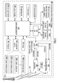
- FIG. 3 illustrates an example arrangement of internal components of the mobile communication device 100.
- a processing device (a microprocessor 328) is shown schematically in FIG. 3 as coupled between the keyboard 124 and the display 126.
- the microprocessor 328 controls the operation of the display 126, as well as the overall operation of the mobile communication device 100, in part, responsive to actuation of the keys on the keyboard 124 by a user.
- the mobile communication device 100 may include a communications subsystem 302, a short-range communications subsystem 304, the keyboard 124 and the display 126.
- the mobile communication device 100 may further include other input/output devices, such as a set of auxiliary I/O devices 306, a serial port 308, the speaker 111 and a microphone 312.
- the mobile communication device 100 may further include memory devices including a flash memory 316 and a Random Access Memory (RAM) 318 as well as various other device subsystems.
- the mobile communication device 100 may comprise a two-way, radio frequency (RF) communication device having voice and data communication capabilities.
- the mobile communication device 100 may have the capability to communicate with other computer systems via the Internet.
- RF radio frequency
- Operating system software executed by the microprocessor 328 may be stored in a computer readable medium, such as the flash memory 316, but may be stored in other types of memory devices, such as a read only memory (ROM) or similar storage element.
- system software, specific device applications, or parts thereof may be temporarily loaded into a volatile store, such as the RAM 318. Communication signals received by the mobile device may also be stored to the RAM 318.
- the microprocessor 328 in addition to its operating system functions, enables execution of software applications on the mobile communication device 100.
- a predetermined set of software applications that control basic device operations such as a voice communications module 330A and a data communications module 330B, may be installed on the mobile communication device 100 during manufacture.
- An authentication module 330C may also be installed on the mobile communication device 100 during manufacture, to implement aspects of the present disclosure.
- additional software modules illustrated as an other software module 330N, which may be, for instance, a PIM application, may be installed during manufacture.
- the PIM application may be capable of organizing and managing data items, such as e-mail messages, calendar events, voice mail messages, appointments and task items.
- the PIM application may also be capable of sending and receiving data items via a wireless carrier network 370 represented by a radio tower.
- the data items managed by the PIM application may be seamlessly integrated, synchronized and updated via the wireless carrier network 370 with the device user's corresponding data items stored or associated with a host computer system.
- the communication subsystem 302 includes a receiver 350, a transmitter 352 and one or more antennas, illustrated as a receive antenna 354 and a transmit antenna 356.
- the communication subsystem 302 also includes a processing module, such as a digital signal processor (DSP) 358, and local oscillators (LOs) 360.
- DSP digital signal processor
- LOs local oscillators
- the communication subsystem 302 of the mobile communication device 100 may be designed to operate with the MobitexTM, DataTACTM or General Packet Radio Service (GPRS) mobile data communication networks and also designed to operate with any of a variety of voice communication networks, such as Advanced Mobile Phone Service (AMPS), Time Division Multiple Access (TDMA), Code Division Multiple Access (CDMA), Personal Communications Service (PCS), Global System for Mobile Communications (GSM), Enhanced Data rates for GSM Evolution (EDGE), Universal Mobile Telecommunications System (UMTS), Wideband Code Division Multiple Access (W-CDMA), High Speed Packet Access (HSPA), etc.
- AMPS Advanced Mobile Phone Service
- TDMA Time Division Multiple Access
- CDMA Code Division Multiple Access
- PCS Personal Communications Service
- GSM Global System for Mobile Communications
- EDGE Enhanced Data rates for GSM Evolution
- UMTS Universal Mobile Telecommunications System
- W-CDMA Wideband Code Division Multiple Access
- HSPA High Speed Packet Access
- Other types of data and voice networks, both separate and integrated, may also be utilized
- Network access requirements vary depending upon the type of communication system.
- an identifier is associated with each mobile device that uniquely identifies the mobile device or subscriber to which the mobile device has been assigned.
- the identifier is unique within a specific network or network technology.
- MobitexTM networks mobile devices are registered on the network using a Mobitex Access Number (MAN) associated with each device and in DataTACTM networks, mobile devices are registered on the network using a Logical Link Identifier (LLI) associated with each device.
- MAN Mobitex Access Number
- LLI Logical Link Identifier
- SIM Subscriber Identity Module
- a GPRS device therefore uses a subscriber identity module, commonly referred to as a Subscriber Identity Module (SIM) card, in order to operate on a GPRS network.
- SIM Subscriber Identity Module
- IMEI International Mobile Equipment Identity
- the mobile communication device 100 may send and receive communication signals over the wireless carrier network 370.
- Signals received from the wireless carrier network 370 by the receive antenna 354 are routed to the receiver 350, which provides for signal amplification, frequency down conversion, filtering, channel selection, etc., and may also provide analog to digital conversion. Analog-to-digital conversion of the received signal allows the DSP 358 to perform more complex communication functions, such as demodulation and decoding.
- signals to be transmitted to the wireless carrier network 370 are processed (e.g., modulated and encoded) by the DSP 358 and are then provided to the transmitter 352 for digital to analog conversion, frequency up conversion, filtering, amplification and transmission to the wireless carrier network 370 (or networks) via the transmit antenna 356.
- the DSP 358 provides for control of the receiver 350 and the transmitter 352. For example, gains applied to communication signals in the receiver 350 and the transmitter 352 may be adaptively controlled through automatic gain control algorithms implemented in the DSP 358.
- a received signal such as a text message or web page download
- the communication subsystem 302 is input to the microprocessor 328.
- the received signal is then further processed by the microprocessor 328 for output to the display 126, or alternatively to some auxiliary I/O devices 306.
- a device user may also compose data items, such as e-mail messages, using the keyboard 124 and/or some other auxiliary I/O device 306, such as the navigation device 106, a touchpad, a rocker switch, a thumb-wheel, a trackball, a touchscreen, or some other type of input device.
- the composed data items may then be transmitted over the wireless carrier network 370 via the communication subsystem 302.
- a voice communication mode In a voice communication mode, overall operation of the device is substantially similar to the data communication mode, except that received signals are output to the speaker 111, and signals for transmission are generated by a microphone 312.
- Alternative voice or audio I/O subsystems such as a voice message recording subsystem, may also be implemented on the mobile communication device 100.
- the display 126 may also be utilized in voice communication mode, for example, to display the identity of a calling party, the duration of a voice call, or other voice call related information.
- the short-range communications subsystem 304 enables communication between the mobile communication device 100 and other proximate systems or devices, which need not necessarily be similar devices.
- the short-range communications subsystem may include an infrared device and associated circuits and components, or a BluetoothTM communication module to provide for communication with similarly-enabled systems and devices.
- An anterior photography subsystem 320A and a posterior photography subsystem 320P connect to the microprocessor 328 via an Image Signal Processor (ISP) 321.
- ISP Image Signal Processor
- the anterior photography subsystem 320A and the posterior photography subsystem 320P each include a communication interface (not shown) for managing communication with the ISP 321.
- FIG. 4 An example arrangement of components of the anterior photography subsystem 320A is schematically illustrated in FIG. 4 as including a capacitive touch sensor 402, the anterior lens 103A, an anterior shutter 404, an autofocus module 408, an image sensor 406, a light source 412, a memory 414 and an anterior photography subsystem processor 410.
- the capacitive touch sensor 402 is arranged to overlay the anterior lens 103A and communicate with the anterior photography subsystem processor 410.
- the anterior shutter 404 may be arranged to selectively, under control of the anterior photography subsystem processor 410, allow light that passes through the anterior lens 103A to reach the image sensor 406.
- the function of the anterior shutter 404 may be accomplished by selectively activating portions of the image sensor 406.
- a shutter that implements a combination of mechanical and electronic shutter strategies is also available as a further alternative.
- the anterior photography subsystem processor 410 also exerts control, via the autofocus module 408, over the focal length of the light that passes through the anterior lens 103A toward the image sensor 406.
- the light source 412 is also under control of the anterior photography subsystem processor 410.
- a set of operating instructions may be installed in the memory 414 during manufacture, to allow the anterior photography subsystem processor 410 to implement aspects of the present disclosure.
- the posterior photography subsystem 320P may include the posterior lens 103P with corresponding posterior shutter (not shown), the LED 207, an image sensor (not shown) and a posterior photography subsystem processor (not shown).
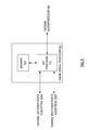
- FIG. 5 illustrates an example of the components of the ISP 321 for the mobile communication device 100 of FIG. 1 .
- the ISP 321 may include an ISP processor 510 and an ISP memory 514.
- the ISP memory 514 may be used to buffer received data and may also store computer readable instructions for use by the ISP processor 510.
- the ISP memory 514 is likely to be small and embedded within the ISP processor 510.
- the ISP memory 514 is shown separately merely for purposes of illustration and should not preclude the option that the ISP memory 514 is implemented in the ISP processor 510.
- the anterior photography subsystem 320A may be used when obtaining a candidate fingerprint for the mobile communication device 100 (e.g., for authentication purposes).
- the anterior photography subsystem 320A may be adapted, according to the present disclosure, to automatically adjust focal length from around one meter (e.g., for self portraits and video calls) to around one millimeter (e.g., for fingerprint capture).
- the mobile communication device 100 may be arranged to have various security modes including, for example, a locked mode and an unlocked mode.
- the mobile communication device 100 may be capable of receiving incoming telephone calls or place an emergency telephone call while in locked mode. Additionally, the mobile communication device 100 may be capable of receiving messages (e.g., e-mail messages, Short Messaging Service messages, instant messenger messages, etc.), but the messages may not be viewed by the user while the device is in locked mode.
- the mobile communication device 100 can do little else but provide a dialog indicating that the mobile communication device 100 is in locked mode and indicating the action that is to be taken by the user to change the mode of the mobile communication device 100 to unlocked mode. Upon changing the mode of the mobile communication device 100 to unlocked mode, the user may be provided much greater access to the functionality of the mobile communication device 100.
- Such authentication input may take the form of input provided on the keyboard 124, where the input may be a password formed of alphanumeric characters and/or symbols.
- Such authentication input may take the form of biometric input.
- Biometric input may include one or more fingerprints, retinal scans, face geometry scans, hand geometry scans, voice prints or speech prints, etc.
- One example fingerprint sensor has a bar shape.
- a silicon sensor constructs a fingerprint as a user swipes a finger across the bar.
- Another example fingerprint sensor has a pad shape.
- a sensor constructs a fingerprint as a user holds a finger on the pad, which is designed with a size to accommodate an entire fingerprint.
- anterior photography subsystem 320A it is proposed herein to employ the anterior photography subsystem 320A in place of a dedicated fingerprint sensor.
- anterior photography subsystem 320A requires an optics system that can focus at both approximately 1 millimeter (for fingerprint capture) and 1 meter (for normal camera operation).
- an anterior photography subsystem for a mobile communication device is not constantly in use. It is anticipated that the anterior photography subsystem 320A will occasionally be called upon, for example, to capture a photograph, to capture video or to capture a candidate digital fingerprint.
- the anterior photography subsystem 320A may be arranged to receive (step 602) an instruction from the ISP processor 510, where the instruction initializes operation of the anterior photography subsystem 320A. Responsive to receiving (step 602) the instruction, the anterior photography subsystem processor 410 may determine (step 604) whether fingerprint scanning mode is to be activated.
- the instruction from the ISP processor 510 may be transmitted responsive to receipt, by the ISP processor 510, of an instruction from the microprocessor 328.
- the microprocessor 328 determines whether the anterior photography subsystem 320A is to operate in fingerprint scanning mode or normal mode and indicates a requested mode in the instruction to the ISP processor 510. It is expected that fingerprint scanning mode will be used most often when the mobile communication device 100 is in locked mode and that normal mode will be used most often when the mobile communication device 100 is in unlocked mode.
- determining (step 604) whether fingerprint scanning mode is to be activated comprises reviewing the instruction received from the ISP processor 510 for an indication of a requested mode.
- the anterior photography subsystem processor 410 may initialize (step 606) operation of the anterior photography subsystem 320A in a normal mode. In the normal mode, the autofocus module 408 operates based on initial conditions that specify that a photographic subject is approximately one meter away from the anterior lens 103A. The anterior photography subsystem 320A may continue to operate in the normal mode until the anterior photography subsystem processor 410 determines (step 608) that an instruction to cease operating has been received from the ISP processor 510.
- the anterior photography subsystem processor 410 may initialize (step 610) operation of the autofocus module 408 in a fingerprint scanning mode.
- the autofocus module 408 operates based on initial conditions that specify that a photographic subject is approximately one millimeter away from the anterior lens 103A.
- Focus at 1 mm may be achieved by physically moving the lens 103A or triggering the ISP 321 to employ digital processing techniques to achieve near field focus of 1 mm.
- the autofocus module 408 may arrange either the physical option or the processor-based option individually or some combination of both options.
- operation of the anterior photography subsystem 320A in the fingerprint scanning mode may also involve the anterior photography subsystem processor 410 activating the light source 412 to shed light on the finger from which a candidate digital fingerprint is to be captured.
- the anterior photography subsystem processor 410 may control the anterior shutter 404 to open and close at a predetermined rate (e.g., 2000 times per second), thereby allowing the image sensor 406 to capture multiple partial digital images of the finger.
- the image sensor 406 may pass the captured multiple partial digital images of the finger to the anterior photography subsystem processor 410.
- the anterior photography subsystem processor 410 may immediately pass the multiple partial digital images of the finger to the ISP 321.
- the anterior photography subsystem processor 410 may store the multiple partial digital images of the finger in the memory 414 for transmission to the ISP 321 at a later time.
- the anterior photography subsystem 320A may continue to operate in the fingerprint scanning mode until the anterior photography subsystem processor 410 determines (step 612) that fingerprint capture is complete.
- FIG. 7 illustrates example steps in a method of operation for the ISP processor 510.
- the ISP processor 510 may, upon receipt (step 702) of the multiple partial digital images of the finger from the anterior photography subsystem 320A, combine the multiple partial digital images to form (step 704) a candidate digital fingerprint. The ISP may then determine (step 706) whether the formed candidate digital fingerprint is suitable for use by the authentication module 330C.
- a typical fingerprint identification algorithm seeks to detect, in a candidate digital fingerprint, a number of "features" suitable to enable an adequate level of discrimination relative to other fingerprints not from the enrolled user.
- a candidate digital fingerprint may be determined (step 706) to be suitable for use by the authentication module 330C based on the detection, in the candidate digital fingerprint, of a number of features exceeding a predetermined threshold number of features.
- the predetermined threshold number of features is dependent on a level of discrimination desired (say, 1 in 1 000, 1 in 10 000, 1 in 1 000 000, etc.).
- the ISP processor 510 may transmit (step 708) a request to the anterior photography subsystem 320A for further partial digital images.
- the ISP processor 510 may transmit (step 710), to the anterior photography subsystem 320A, a confirmation that the fingerprint has been successfully captured. The ISP processor 510 may then transmit (step 712) the candidate digital fingerprint to the microprocessor 328.
- the microprocessor 328 may implement the authentication module 330C to perform a conventional comparison of the received candidate digital fingerprint to a previously stored template digital fingerprint.
- the result of the comparison may be represented by a value representative of a degree of match between the candidate and the template. Based on the degree of match, the microprocessor 328 may unlock the mobile communication device 100 for use by the user.
- an authentication dialog presented on the display 126 under control of the microprocessor 328 may require a combination of password and one or more fingerprints to successfully unlock the mobile communication device 100.
- the use of a single fingerprint has been described above for simplicity of presentation.
- determining (step 604) whether fingerprint scanning mode is to be activated comprises reviewing the instruction received from the ISP 321 for an indication of a requested mode.
- the instruction received from the ISP 321 may merely activate the anterior photography subsystem 320A and leave the decision the anterior photography subsystem processor 410.
- Determining (step 604) whether fingerprint scanning mode is to be activated may, in this implementation, comprise receiving (or not receiving) input from the capacitive touch sensor 402. Based on receiving input from the capacitive touch sensor 402, the anterior photography subsystem processor 410 may determine (step 604) that fingerprint scanning mode is to be activated. Based on a lack of input from the capacitive touch sensor 402, the anterior photography subsystem processor 410 may determine (step 604) that normal mode is to be activated.
- components of the anterior photography subsystem 320A may be arranged to capture multiple digital images at different focal distances.
- the anterior photography subsystem processor 410 may transmit each of the multiple digital images at different focal distances to the ISP 321.
- the ISP processor 510 Responsive to receiving the multiple digital images at different focal distances, the ISP processor 510 employs a digital image processing technique to combine the images to form an image with an extended depth of field (EDOF). Based on the active mode (e.g., normal or fingerprint scanning), the ISP processor 510 uses de-convolution algorithms to form a normal mode image or a candidate digital fingerprint.
- EDOF extended depth of field
- FIG. 8 illustrates an anterior side of a modified mobile communication device 800 that is an alternative to the mobile communication device 100 of FIG. 1 .
- the modified mobile communication device 800 includes features a display 826, a keyboard 824 having a plurality of keys and a speaker 811 mounted within a housing 801.
- the modified mobile communication device 800 differs from the mobile communication device 100 of FIG. 1 in that a navigation device and an anterior (user-facing) lens have been combined into a single optical navigation module 806.
- an anterior photography and optical navigation subsystem (not shown) supporting the optical navigation module 806 may be required to be active while the mobile communication device 100 is in operation, such that the anterior photography and optical navigation subsystem may act in its navigation capacity to report navigation finger motion (up, down, left, right, etc.) to the microprocessor 328.
- the structure of the anterior photography and optical navigation subsystem may closely follow the structure of the anterior photography subsystem 320A illustrated in FIG. 4 .
- the anterior photography and optical navigation subsystem may be configured to switch from a navigation mode to a fingerprint capture mode or from the fingerprint capture mode to the navigation mode responsive to an instruction to do so received from the ISP 321.
- the ISP processor 510 receives images from the anterior photography and optical navigation subsystem and processes determine a directional vector of any finger movement taking place.
- the disclosure has concentrated on the anterior photography subsystem 320A as a component to capture fingerprints, it should be clear that, if desired, the posterior photography subsystem 320P may be used, additionally or alternatively, to capture images from which may be formed a candidate digital fingerprint.
Abstract
Description
- The present application relates generally to authentication for a computing device and, more specifically, to fingerprint scanning with a camera.
- As mobile telephones has received increasing amounts of computing power in successive generations, the mobile telephones have been termed "smart phones". Along with increasing amounts of computing power, such smart phones have seen increases in storage capacity and, consequently, increased utility. Beyond telephone functions, smart phones may now send and receive digital messages, be they formatted to use e-mail standards, Short Messaging Service (SMS) standards, Instant Messaging standards and proprietary messaging systems. Smart phones may also store, read, edit and create documents, spreadsheets and presentations. Accordingly, there have been increasing demands for smart phones with enhanced authentication functions.
- Rather than providing separate hardware for two distinct functions, photography and fingerprint capture, the functions may be carried out by a single subsystem. That is, a photography subsystem may be configured to be operated in fingerprint scanning mode and a normal mode. An autofocus module may be initialized to control a lens with an initial focal length set according to received instructions indicating one of the modes of operation. An image signal processor associated with the photography subsystem may process images received from the photography subsystem and, if necessary, process the images to form a candidate digital fingerprint for use in an authentication process.
- According to an aspect of the present disclosure, there is provided a method of operating a photography subsystem. The method includes receiving input from a capacitive touch sensor proximate to a lens, responsive to the receiving, determining that the photography subsystem is to be operated in fingerprint scanning mode, operating the photography subsystem in fingerprint scanning mode, wherein operating the photography subsystem in fingerprint scanning mode includes initializing an autofocus module to control the lens with an initial focal length set for fingerprint capture, receiving, from an image sensor, a digital image and storing the digital image in a memory.
- According to another aspect of the present disclosure, there is provided a photography subsystem. The photography subsystem includes a processor adapted to determine that the photography subsystem is to be operated in fingerprint scanning mode and operate the photography subsystem in fingerprint scanning mode.
- According to a further aspect of the present disclosure, there is provided a computer readable medium containing computer-executable instructions. The instructions, when performed by a processor for a photography subsystem, cause the processor to determine that the photography subsystem is to be operated in fingerprint scanning mode and operate the photography subsystem in fingerprint scanning mode.
- According to an even further aspect of the present disclosure, there is provided a method of operating an image signal processor to facilitate digital fingerprint capture. The method includes receiving, from a photography subsystem, a plurality of partial digital fingerprint images, forming, based on the plurality of partial digital fingerprint images, a candidate digital fingerprint and transmitting the candidate digital fingerprint. In other aspects of the present application, an image signal processor is provided for carrying out this method and a computer readable medium is provided for adapting a processor in an image signal processor to carry out this method.
- Other aspects and features of the present disclosure will become apparent to those of ordinary skill in the art upon review of the following description of specific implementations of the disclosure in conjunction with the accompanying figures.
- Reference will now be made to the drawings, which show by way of example, implementations of the present disclosure, and in which:
-
FIG. 1 illustrates an anterior side of a mobile communication device; -
FIG. 2 illustrates a posterior side of the mobile communication device ofFIG. 1 ; -
FIG. 3 illustrates an example arrangement of internal components of the mobile communication device ofFIG. 1 , in accordance with an implementation of the present disclosure; -
FIG. 4 illustrates an example anterior photography subsystem for the mobile communication device ofFIG. 1 , in accordance with an implementation of the present disclosure; -
FIG. 5 illustrates an example image signal processor for the mobile communication device ofFIG. 1 , in accordance with an implementation of the present disclosure; -
FIG. 6 illustrates example steps in a method of switching between a normal mode of operation and a fingerprint scanning mode of operation for the anterior photography subsystem ofFIG. 4 , in accordance with an implementation of the present disclosure; -
FIG. 7 illustrates example steps in a method of operation for the image signal processor ofFIG. 5 , in accordance with an implementation of the present disclosure; and -
FIG. 8 illustrates an anterior side of a modified mobile communication device that is an alternative to the mobile communication device ofFIG. 1 , in accordance with an implementation of the present disclosure. -
FIG. 1 illustrates an anterior side of amobile communication device 100. Many features of the anterior side of themobile communication device 100 are mounted within ahousing 101 and include adisplay 126, akeyboard 124 having a plurality of keys, aspeaker 111, a navigation device 106 (e.g., a touchpad, a trackball, a touchscreen, an optical navigation module) and an anterior (user-facing)lens 103A. - The
mobile communication device 100 includes an input device (e.g., the keyboard 124) and an output device (e.g., the display 126), which may comprise a full graphic, or full color, Liquid Crystal Display (LCD). In some implementations, thedisplay 126 may comprise a touchscreen display. In such touchscreen implementations, thekeyboard 124 may comprise a virtual keyboard provided on thedisplay 126. Other types of output devices may alternatively be utilized. - The
housing 101 may be elongated vertically, or may take on other sizes and shapes (including clamshell housing structures). In the case in which thekeyboard 124 includes keys that are associated with at least one alphabetic character and at least one numeric character, thekeyboard 124 may include a mode selection key, or other hardware or software, for switching between alphabetic entry and numeric entry. -
FIG. 2 illustrates a posterior side of themobile communication device 100. Included on the posterior side are aposterior lens 103P and a Light Emitting Diode (LED) 207 for use as a flash when using themobile communication device 100 to capture, through theposterior lens 103P, a still photograph. TheLED 207 may also be used as a torch to provide light when themobile communication device 100 is used to capture, through theposterior lens 103P, video in low ambient light. -
FIG. 3 illustrates an example arrangement of internal components of themobile communication device 100. A processing device (a microprocessor 328) is shown schematically inFIG. 3 as coupled between thekeyboard 124 and thedisplay 126. Themicroprocessor 328 controls the operation of thedisplay 126, as well as the overall operation of themobile communication device 100, in part, responsive to actuation of the keys on thekeyboard 124 by a user. - In addition to the
microprocessor 328, other parts of themobile communication device 100 are shown schematically inFIG. 3 . These may include acommunications subsystem 302, a short-range communications subsystem 304, thekeyboard 124 and thedisplay 126. Themobile communication device 100 may further include other input/output devices, such as a set of auxiliary I/O devices 306, aserial port 308, thespeaker 111 and amicrophone 312. Themobile communication device 100 may further include memory devices including aflash memory 316 and a Random Access Memory (RAM) 318 as well as various other device subsystems. Themobile communication device 100 may comprise a two-way, radio frequency (RF) communication device having voice and data communication capabilities. In addition, themobile communication device 100 may have the capability to communicate with other computer systems via the Internet. - Operating system software executed by the
microprocessor 328 may be stored in a computer readable medium, such as theflash memory 316, but may be stored in other types of memory devices, such as a read only memory (ROM) or similar storage element. In addition, system software, specific device applications, or parts thereof, may be temporarily loaded into a volatile store, such as theRAM 318. Communication signals received by the mobile device may also be stored to theRAM 318. - The
microprocessor 328, in addition to its operating system functions, enables execution of software applications on themobile communication device 100. A predetermined set of software applications that control basic device operations, such as avoice communications module 330A and adata communications module 330B, may be installed on themobile communication device 100 during manufacture. Anauthentication module 330C may also be installed on themobile communication device 100 during manufacture, to implement aspects of the present disclosure. As well, additional software modules, illustrated as another software module 330N, which may be, for instance, a PIM application, may be installed during manufacture. The PIM application may be capable of organizing and managing data items, such as e-mail messages, calendar events, voice mail messages, appointments and task items. The PIM application may also be capable of sending and receiving data items via awireless carrier network 370 represented by a radio tower. The data items managed by the PIM application may be seamlessly integrated, synchronized and updated via thewireless carrier network 370 with the device user's corresponding data items stored or associated with a host computer system. - Communication functions, including data and voice communications, are performed through the
communication subsystem 302 and, possibly, through the short-range communications subsystem 304. Thecommunication subsystem 302 includes areceiver 350, atransmitter 352 and one or more antennas, illustrated as areceive antenna 354 and atransmit antenna 356. In addition, thecommunication subsystem 302 also includes a processing module, such as a digital signal processor (DSP) 358, and local oscillators (LOs) 360. The specific design and implementation of thecommunication subsystem 302 is dependent upon the communication network in which themobile communication device 100 is intended to operate. For example, thecommunication subsystem 302 of themobile communication device 100 may be designed to operate with the Mobitex™, DataTAC™ or General Packet Radio Service (GPRS) mobile data communication networks and also designed to operate with any of a variety of voice communication networks, such as Advanced Mobile Phone Service (AMPS), Time Division Multiple Access (TDMA), Code Division Multiple Access (CDMA), Personal Communications Service (PCS), Global System for Mobile Communications (GSM), Enhanced Data rates for GSM Evolution (EDGE), Universal Mobile Telecommunications System (UMTS), Wideband Code Division Multiple Access (W-CDMA), High Speed Packet Access (HSPA), etc. Other types of data and voice networks, both separate and integrated, may also be utilized with themobile communication device 100. - Network access requirements vary depending upon the type of communication system. Typically, an identifier is associated with each mobile device that uniquely identifies the mobile device or subscriber to which the mobile device has been assigned. The identifier is unique within a specific network or network technology. For example, in Mobitex™ networks, mobile devices are registered on the network using a Mobitex Access Number (MAN) associated with each device and in DataTAC™ networks, mobile devices are registered on the network using a Logical Link Identifier (LLI) associated with each device. In GPRS networks, however, network access is associated with a subscriber or user of a device. A GPRS device therefore uses a subscriber identity module, commonly referred to as a Subscriber Identity Module (SIM) card, in order to operate on a GPRS network. Despite identifying a subscriber by SIM, mobile devices within GSM/GPRS networks are uniquely identified using an International Mobile Equipment Identity (IMEI) number.
- When required network registration or activation procedures have been completed, the
mobile communication device 100 may send and receive communication signals over thewireless carrier network 370. Signals received from thewireless carrier network 370 by the receiveantenna 354 are routed to thereceiver 350, which provides for signal amplification, frequency down conversion, filtering, channel selection, etc., and may also provide analog to digital conversion. Analog-to-digital conversion of the received signal allows theDSP 358 to perform more complex communication functions, such as demodulation and decoding. In a similar manner, signals to be transmitted to thewireless carrier network 370 are processed (e.g., modulated and encoded) by theDSP 358 and are then provided to thetransmitter 352 for digital to analog conversion, frequency up conversion, filtering, amplification and transmission to the wireless carrier network 370 (or networks) via the transmitantenna 356. - In addition to processing communication signals, the
DSP 358 provides for control of thereceiver 350 and thetransmitter 352. For example, gains applied to communication signals in thereceiver 350 and thetransmitter 352 may be adaptively controlled through automatic gain control algorithms implemented in theDSP 358. - In a data communication mode, a received signal, such as a text message or web page download, is processed by the
communication subsystem 302 and is input to themicroprocessor 328. The received signal is then further processed by themicroprocessor 328 for output to thedisplay 126, or alternatively to some auxiliary I/O devices 306. A device user may also compose data items, such as e-mail messages, using thekeyboard 124 and/or some other auxiliary I/O device 306, such as thenavigation device 106, a touchpad, a rocker switch, a thumb-wheel, a trackball, a touchscreen, or some other type of input device. The composed data items may then be transmitted over thewireless carrier network 370 via thecommunication subsystem 302. - In a voice communication mode, overall operation of the device is substantially similar to the data communication mode, except that received signals are output to the
speaker 111, and signals for transmission are generated by amicrophone 312. Alternative voice or audio I/O subsystems, such as a voice message recording subsystem, may also be implemented on themobile communication device 100. In addition, thedisplay 126 may also be utilized in voice communication mode, for example, to display the identity of a calling party, the duration of a voice call, or other voice call related information. - The short-
range communications subsystem 304 enables communication between themobile communication device 100 and other proximate systems or devices, which need not necessarily be similar devices. For example, the short-range communications subsystem may include an infrared device and associated circuits and components, or a Bluetooth™ communication module to provide for communication with similarly-enabled systems and devices. - An
anterior photography subsystem 320A and aposterior photography subsystem 320P connect to themicroprocessor 328 via an Image Signal Processor (ISP) 321. Indeed, theanterior photography subsystem 320A and theposterior photography subsystem 320P each include a communication interface (not shown) for managing communication with theISP 321. - An example arrangement of components of the
anterior photography subsystem 320A is schematically illustrated inFIG. 4 as including acapacitive touch sensor 402, theanterior lens 103A, ananterior shutter 404, anautofocus module 408, animage sensor 406, alight source 412, amemory 414 and an anteriorphotography subsystem processor 410. Thecapacitive touch sensor 402 is arranged to overlay theanterior lens 103A and communicate with the anteriorphotography subsystem processor 410. In a mechanical manifestation, theanterior shutter 404 may be arranged to selectively, under control of the anteriorphotography subsystem processor 410, allow light that passes through theanterior lens 103A to reach theimage sensor 406. In an electronic manifestation, the function of theanterior shutter 404 may be accomplished by selectively activating portions of theimage sensor 406. A shutter that implements a combination of mechanical and electronic shutter strategies is also available as a further alternative. - The anterior
photography subsystem processor 410 also exerts control, via theautofocus module 408, over the focal length of the light that passes through theanterior lens 103A toward theimage sensor 406. Thelight source 412 is also under control of the anteriorphotography subsystem processor 410. - A set of operating instructions may be installed in the
memory 414 during manufacture, to allow the anteriorphotography subsystem processor 410 to implement aspects of the present disclosure. - The
posterior photography subsystem 320P may include theposterior lens 103P with corresponding posterior shutter (not shown), theLED 207, an image sensor (not shown) and a posterior photography subsystem processor (not shown). -
FIG. 5 illustrates an example of the components of theISP 321 for themobile communication device 100 ofFIG. 1 . In particular, theISP 321 may include anISP processor 510 and anISP memory 514. TheISP memory 514 may be used to buffer received data and may also store computer readable instructions for use by theISP processor 510. Notably, theISP memory 514 is likely to be small and embedded within theISP processor 510. TheISP memory 514 is shown separately merely for purposes of illustration and should not preclude the option that theISP memory 514 is implemented in theISP processor 510. - In overview, the
anterior photography subsystem 320A may be used when obtaining a candidate fingerprint for the mobile communication device 100 (e.g., for authentication purposes). To accommodate such use of thephotography subsystem 320A, theanterior photography subsystem 320A may be adapted, according to the present disclosure, to automatically adjust focal length from around one meter (e.g., for self portraits and video calls) to around one millimeter (e.g., for fingerprint capture). - The
mobile communication device 100 may be arranged to have various security modes including, for example, a locked mode and an unlocked mode. - In locked mode, a user has limited access to the functions of the
mobile communication device 100. Themobile communication device 100 may be capable of receiving incoming telephone calls or place an emergency telephone call while in locked mode. Additionally, themobile communication device 100 may be capable of receiving messages (e.g., e-mail messages, Short Messaging Service messages, instant messenger messages, etc.), but the messages may not be viewed by the user while the device is in locked mode. Themobile communication device 100 can do little else but provide a dialog indicating that themobile communication device 100 is in locked mode and indicating the action that is to be taken by the user to change the mode of themobile communication device 100 to unlocked mode. Upon changing the mode of themobile communication device 100 to unlocked mode, the user may be provided much greater access to the functionality of themobile communication device 100. - When the
mobile communication device 100 is in locked mode, there may exist a requirement that a user provide, to themobile communication device 100, one or more forms of authentication input before themobile communication device 100 will change over to unlocked mode. Such authentication input may take the form of input provided on thekeyboard 124, where the input may be a password formed of alphanumeric characters and/or symbols. Alternatively or additionally, such authentication input may take the form of biometric input. Biometric input may include one or more fingerprints, retinal scans, face geometry scans, hand geometry scans, voice prints or speech prints, etc. - In recognition of the security provided by biometric authentication, manufacturers of mobile communication devices such as notebook computers, cellular telephones and so-called smart phones, which combine elements of notebook computers and cellular telephones, have been known to include a built-in fingerprint sensor in their products.
- One example fingerprint sensor has a bar shape. A silicon sensor constructs a fingerprint as a user swipes a finger across the bar. Another example fingerprint sensor has a pad shape. A sensor constructs a fingerprint as a user holds a finger on the pad, which is designed with a size to accommodate an entire fingerprint.
- It is proposed herein to employ the
anterior photography subsystem 320A in place of a dedicated fingerprint sensor. However, such employment of theanterior photography subsystem 320A requires an optics system that can focus at both approximately 1 millimeter (for fingerprint capture) and 1 meter (for normal camera operation). - As will be clear to a person of skill in the art, in general, an anterior photography subsystem for a mobile communication device is not constantly in use. It is anticipated that the
anterior photography subsystem 320A will occasionally be called upon, for example, to capture a photograph, to capture video or to capture a candidate digital fingerprint. - In operation, in view of
FIG. 6 , theanterior photography subsystem 320A may be arranged to receive (step 602) an instruction from theISP processor 510, where the instruction initializes operation of theanterior photography subsystem 320A. Responsive to receiving (step 602) the instruction, the anteriorphotography subsystem processor 410 may determine (step 604) whether fingerprint scanning mode is to be activated. - The instruction from the
ISP processor 510 may be transmitted responsive to receipt, by theISP processor 510, of an instruction from themicroprocessor 328. In one implementation, themicroprocessor 328 determines whether theanterior photography subsystem 320A is to operate in fingerprint scanning mode or normal mode and indicates a requested mode in the instruction to theISP processor 510. It is expected that fingerprint scanning mode will be used most often when themobile communication device 100 is in locked mode and that normal mode will be used most often when themobile communication device 100 is in unlocked mode. - Accordingly, in one implementation, determining (step 604) whether fingerprint scanning mode is to be activated comprises reviewing the instruction received from the
ISP processor 510 for an indication of a requested mode. - Upon determining (step 604) that fingerprint scanning mode is not to be activated, the anterior
photography subsystem processor 410 may initialize (step 606) operation of theanterior photography subsystem 320A in a normal mode. In the normal mode, theautofocus module 408 operates based on initial conditions that specify that a photographic subject is approximately one meter away from theanterior lens 103A. Theanterior photography subsystem 320A may continue to operate in the normal mode until the anteriorphotography subsystem processor 410 determines (step 608) that an instruction to cease operating has been received from theISP processor 510. - Upon determining (step 604) that fingerprint scanning mode is to be activated, the anterior
photography subsystem processor 410 may initialize (step 610) operation of theautofocus module 408 in a fingerprint scanning mode. In the fingerprint scanning mode, theautofocus module 408 operates based on initial conditions that specify that a photographic subject is approximately one millimeter away from theanterior lens 103A. - Focus at 1 mm (fingerprint scanning mode) may be achieved by physically moving the
lens 103A or triggering theISP 321 to employ digital processing techniques to achieve near field focus of 1 mm. In general, theautofocus module 408 may arrange either the physical option or the processor-based option individually or some combination of both options. - Furthermore, operation of the
anterior photography subsystem 320A in the fingerprint scanning mode may also involve the anteriorphotography subsystem processor 410 activating thelight source 412 to shed light on the finger from which a candidate digital fingerprint is to be captured. As the user moves the finger about, the anteriorphotography subsystem processor 410 may control theanterior shutter 404 to open and close at a predetermined rate (e.g., 2000 times per second), thereby allowing theimage sensor 406 to capture multiple partial digital images of the finger. Theimage sensor 406 may pass the captured multiple partial digital images of the finger to the anteriorphotography subsystem processor 410. The anteriorphotography subsystem processor 410 may immediately pass the multiple partial digital images of the finger to theISP 321. Alternatively, the anteriorphotography subsystem processor 410 may store the multiple partial digital images of the finger in thememory 414 for transmission to theISP 321 at a later time. - The
anterior photography subsystem 320A may continue to operate in the fingerprint scanning mode until the anteriorphotography subsystem processor 410 determines (step 612) that fingerprint capture is complete. - As illustrated in
FIG. 3 , theanterior photography subsystem 320A and theposterior photography subsystem 320P connect to thesame ISP 321.FIG. 7 illustrates example steps in a method of operation for theISP processor 510. - It is proposed herein to configure the
ISP processor 510 with image stitching algorithms such that theISP processor 510 may, upon receipt (step 702) of the multiple partial digital images of the finger from theanterior photography subsystem 320A, combine the multiple partial digital images to form (step 704) a candidate digital fingerprint. The ISP may then determine (step 706) whether the formed candidate digital fingerprint is suitable for use by theauthentication module 330C. - A typical fingerprint identification algorithm seeks to detect, in a candidate digital fingerprint, a number of "features" suitable to enable an adequate level of discrimination relative to other fingerprints not from the enrolled user. A candidate digital fingerprint may be determined (step 706) to be suitable for use by the
authentication module 330C based on the detection, in the candidate digital fingerprint, of a number of features exceeding a predetermined threshold number of features. The predetermined threshold number of features is dependent on a level of discrimination desired (say, 1 in 1 000, 1 in 10 000, 1 in 1 000 000, etc.). - Upon determining (step 706) that the candidate digital fingerprint is not yet suitable for use by the
authentication module 330C, theISP processor 510 may transmit (step 708) a request to theanterior photography subsystem 320A for further partial digital images. Upon determining (step 706) that the candidate digital fingerprint is suitable for use by theauthentication module 330C, theISP processor 510 may transmit (step 710), to theanterior photography subsystem 320A, a confirmation that the fingerprint has been successfully captured. TheISP processor 510 may then transmit (step 712) the candidate digital fingerprint to themicroprocessor 328. - Upon receiving the candidate digital fingerprint, the
microprocessor 328 may implement theauthentication module 330C to perform a conventional comparison of the received candidate digital fingerprint to a previously stored template digital fingerprint. The result of the comparison may be represented by a value representative of a degree of match between the candidate and the template. Based on the degree of match, themicroprocessor 328 may unlock themobile communication device 100 for use by the user. - As will be clear to a person of ordinary skill in the art, an authentication dialog presented on the
display 126 under control of themicroprocessor 328 may require a combination of password and one or more fingerprints to successfully unlock themobile communication device 100. The use of a single fingerprint has been described above for simplicity of presentation. - As described above, in one implementation, determining (step 604) whether fingerprint scanning mode is to be activated comprises reviewing the instruction received from the
ISP 321 for an indication of a requested mode. In another implementation, the instruction received from theISP 321 may merely activate theanterior photography subsystem 320A and leave the decision the anteriorphotography subsystem processor 410. Determining (step 604) whether fingerprint scanning mode is to be activated may, in this implementation, comprise receiving (or not receiving) input from thecapacitive touch sensor 402. Based on receiving input from thecapacitive touch sensor 402, the anteriorphotography subsystem processor 410 may determine (step 604) that fingerprint scanning mode is to be activated. Based on a lack of input from thecapacitive touch sensor 402, the anteriorphotography subsystem processor 410 may determine (step 604) that normal mode is to be activated. - Rather than setting initial conditions of the
autofocus module 408 to arrange theanterior lens 103A to focus at one meter (FIG. 6 , step 606) or one millimeter (FIG. 6 , step 610), components of theanterior photography subsystem 320A may be arranged to capture multiple digital images at different focal distances. The anteriorphotography subsystem processor 410 may transmit each of the multiple digital images at different focal distances to theISP 321. - Responsive to receiving the multiple digital images at different focal distances, the
ISP processor 510 employs a digital image processing technique to combine the images to form an image with an extended depth of field (EDOF). Based on the active mode (e.g., normal or fingerprint scanning), theISP processor 510 uses de-convolution algorithms to form a normal mode image or a candidate digital fingerprint. -
FIG. 8 illustrates an anterior side of a modifiedmobile communication device 800 that is an alternative to themobile communication device 100 ofFIG. 1 . In common with themobile communication device 100 ofFIG. 1 , the modifiedmobile communication device 800 includes features adisplay 826, akeyboard 824 having a plurality of keys and aspeaker 811 mounted within ahousing 801. - The modified
mobile communication device 800 differs from themobile communication device 100 ofFIG. 1 in that a navigation device and an anterior (user-facing) lens have been combined into a singleoptical navigation module 806. - Instead of only being active upon receiving instruction from the
microprocessor 328, an anterior photography and optical navigation subsystem (not shown) supporting theoptical navigation module 806 may be required to be active while themobile communication device 100 is in operation, such that the anterior photography and optical navigation subsystem may act in its navigation capacity to report navigation finger motion (up, down, left, right, etc.) to themicroprocessor 328. The structure of the anterior photography and optical navigation subsystem may closely follow the structure of theanterior photography subsystem 320A illustrated inFIG. 4 . The anterior photography and optical navigation subsystem may be configured to switch from a navigation mode to a fingerprint capture mode or from the fingerprint capture mode to the navigation mode responsive to an instruction to do so received from theISP 321. TheISP processor 510 receives images from the anterior photography and optical navigation subsystem and processes determine a directional vector of any finger movement taking place. - Although the disclosure has concentrated on the
anterior photography subsystem 320A as a component to capture fingerprints, it should be clear that, if desired, theposterior photography subsystem 320P may be used, additionally or alternatively, to capture images from which may be formed a candidate digital fingerprint. - The above-described implementations of the present application are intended to be examples only. Alterations, modifications and variations may be effected to the particular implementations by those skilled in the art without departing from the scope of the application, which is defined by the claims appended hereto.
Claims (13)
- A method of operating a photography subsystem (320A), the method comprising:receiving input from a capacitive touch sensor (402) proximate to a lens (103A);responsive to the receiving, determining that the photography subsystem (320A) is to be operated in fingerprint scanning mode;operating the photography subsystem (320A) in fingerprint scanning mode, wherein operating the photography subsystem (320A) in fingerprint scanning mode includes initializing an autofocus module (408) to control the lens (1 03A) with an initial focal length set for fingerprint capture;receiving, from an image sensor (406), a digital image; andstoring the digital image in a memory (414).
- The method of claim 1 wherein the initial focal length is around 1 millimeter.
- The method of claim 1 or claim 2 wherein the operating the photography subsystem in fingerprint scanning mode further comprises triggering an image processor to employ digital processing techniques to achieve near field focus.
- The method of claim 3 wherein the near field focus has a focal length of around 1 millimeter.
- The method of any one of claims 1-5 further comprising transmitting the digital image to an image signal processor.
- The method of claim 5 further comprising:receiving, from the image signal processor, a request for further digital images; andresponsive to the receiving the request, receiving a further digital image and the transmitting the further digital image to the image signal processor.
- A photography subsystem (320A) comprising:a processor (410) adapted to:determine that the photography subsystem is to be operated in fingerprint scanning mode; andoperate the photography subsystem in fingerprint scanning mode.
- The photography subsystem (320A) of claim 7 further comprising:a lens (103A);a capacitive touch sensor (402) proximate to the lens;wherein the processor (410) is further adapted to base the determining that the photography subsystem is to be operated in fingerprint scanning mode on input received from the capacitive touch sensor.
- The photography subsystem (320A) of claim 7 or claim 8 further comprising:a communication interface for managing communication with an image processor;wherein the processor (410) is further adapted to trigger, via the communication interface, the image processor to employ digital processing techniques to achieve near field focus.
- The photography subsystem (320A) of claim 7 further comprising:a lens (103A);an autofocus module (408) adapted to control the lens;wherein the processor (410) is further adapted to initialize the autofocus module (408) to control the lens (103A) with an initial focal length set for fingerprint capture.
- The photography subsystem (320A) of claim 10 wherein the initial focal length is around 1 millimeter.
- The photography subsystem (320A) of any one of claims 7-11 further comprising:an image sensor (406);a memory (414);wherein the processor (410) is further adapted to:receive, from the image sensor (406), a digital image; andstore the digital image in the memory (414).
- A computer readable medium (414) containing computer-executable instructions that, when performed by a processor (410) for a photography subsystem (320A), cause the processor (410) to carry out the method of one of claims 1-6.
Priority Applications (2)
| Application Number | Priority Date | Filing Date | Title |
|---|---|---|---|
| EP10163575A EP2388734A1 (en) | 2010-05-21 | 2010-05-21 | Fingerprint scanning with a camera |
| CA2740624A CA2740624C (en) | 2010-05-21 | 2011-05-19 | Fingerprint scanning with a camera |
Applications Claiming Priority (1)
| Application Number | Priority Date | Filing Date | Title |
|---|---|---|---|
| EP10163575A EP2388734A1 (en) | 2010-05-21 | 2010-05-21 | Fingerprint scanning with a camera |
Publications (1)
| Publication Number | Publication Date |
|---|---|
| EP2388734A1 true EP2388734A1 (en) | 2011-11-23 |
Family
ID=43244720
Family Applications (1)
| Application Number | Title | Priority Date | Filing Date |
|---|---|---|---|
| EP10163575A Ceased EP2388734A1 (en) | 2010-05-21 | 2010-05-21 | Fingerprint scanning with a camera |
Country Status (2)
| Country | Link |
|---|---|
| EP (1) | EP2388734A1 (en) |
| CA (1) | CA2740624C (en) |
Cited By (5)
| Publication number | Priority date | Publication date | Assignee | Title |
|---|---|---|---|---|
| US8943580B2 (en) | 2007-09-24 | 2015-01-27 | Apple Inc. | Embedded authentication systems in an electronic device |
| US9251396B2 (en) | 2013-01-29 | 2016-02-02 | Diamond Fortress Technologies, Inc. | Touchless fingerprinting acquisition and processing application for mobile devices |
| WO2016044804A1 (en) * | 2014-09-18 | 2016-03-24 | Sciometrics Llc | Mobility empowered biometric appliance a tool for real-time verification of identity through fingerprints |
| US9342674B2 (en) | 2003-05-30 | 2016-05-17 | Apple Inc. | Man-machine interface for controlling access to electronic devices |
| US11209961B2 (en) | 2012-05-18 | 2021-12-28 | Apple Inc. | Device, method, and graphical user interface for manipulating user interfaces based on fingerprint sensor inputs |
Citations (11)
| Publication number | Priority date | Publication date | Assignee | Title |
|---|---|---|---|---|
| US20020003892A1 (en) * | 2000-07-10 | 2002-01-10 | Casio Computer Co., Ltd. | Authentication system based on fingerprint and electronic device employed for the system |
| US20020146157A1 (en) * | 2001-04-09 | 2002-10-10 | Goodman Mitchell E. | Fingerprint acquisition assembly using prism and camera |
| US20030036365A1 (en) * | 2001-08-16 | 2003-02-20 | Nec Corporation | Portable communications terminal with camera capable of taking pictures |
| US20030040346A1 (en) * | 2001-08-27 | 2003-02-27 | Olympus Optical Co., Ltd. | Portable information terminal device having camera feature |
| US6532035B1 (en) * | 2000-06-29 | 2003-03-11 | Nokia Mobile Phones Ltd. | Method and apparatus for implementation of close-up imaging capability in a mobile imaging system |
| US20030234867A1 (en) * | 2000-10-12 | 2003-12-25 | Tsutomu Fujita | Information terminal |
| WO2004081852A1 (en) * | 2003-03-14 | 2004-09-23 | Nitgen Co. Ltd. | Information terminal with fingerprint image acquisition device |
| US20060008129A1 (en) * | 2004-07-07 | 2006-01-12 | Dong-Jae Lee | Electronic device with camera and fingerprint security function |
| WO2006002674A1 (en) * | 2004-07-02 | 2006-01-12 | Schölly Fiberoptic GmbH | Device and use thereof for capturing and processing an image |
| US20080049982A1 (en) * | 2003-03-04 | 2008-02-28 | Akio Nagasaka | Personal authentication device |
| US20100048241A1 (en) * | 2008-08-21 | 2010-02-25 | Seguin Chad G | Camera as input interface |
-
2010
- 2010-05-21 EP EP10163575A patent/EP2388734A1/en not_active Ceased
-
2011
- 2011-05-19 CA CA2740624A patent/CA2740624C/en active Active
Patent Citations (11)
| Publication number | Priority date | Publication date | Assignee | Title |
|---|---|---|---|---|
| US6532035B1 (en) * | 2000-06-29 | 2003-03-11 | Nokia Mobile Phones Ltd. | Method and apparatus for implementation of close-up imaging capability in a mobile imaging system |
| US20020003892A1 (en) * | 2000-07-10 | 2002-01-10 | Casio Computer Co., Ltd. | Authentication system based on fingerprint and electronic device employed for the system |
| US20030234867A1 (en) * | 2000-10-12 | 2003-12-25 | Tsutomu Fujita | Information terminal |
| US20020146157A1 (en) * | 2001-04-09 | 2002-10-10 | Goodman Mitchell E. | Fingerprint acquisition assembly using prism and camera |
| US20030036365A1 (en) * | 2001-08-16 | 2003-02-20 | Nec Corporation | Portable communications terminal with camera capable of taking pictures |
| US20030040346A1 (en) * | 2001-08-27 | 2003-02-27 | Olympus Optical Co., Ltd. | Portable information terminal device having camera feature |
| US20080049982A1 (en) * | 2003-03-04 | 2008-02-28 | Akio Nagasaka | Personal authentication device |
| WO2004081852A1 (en) * | 2003-03-14 | 2004-09-23 | Nitgen Co. Ltd. | Information terminal with fingerprint image acquisition device |
| WO2006002674A1 (en) * | 2004-07-02 | 2006-01-12 | Schölly Fiberoptic GmbH | Device and use thereof for capturing and processing an image |
| US20060008129A1 (en) * | 2004-07-07 | 2006-01-12 | Dong-Jae Lee | Electronic device with camera and fingerprint security function |
| US20100048241A1 (en) * | 2008-08-21 | 2010-02-25 | Seguin Chad G | Camera as input interface |
Non-Patent Citations (1)
| Title |
|---|
| DONGJAE LEE ET AL: "Recognizable-Image Selection for Fingerprint Recognition With a Mobile-Device Camera", IEEE TRANSACTIONS ON SYSTEMS, MAN AND CYBERNETICS. PART B:CYBERNETICS, IEEE SERVICE CENTER, PISCATAWAY, NJ, US, vol. 38, no. 1, 1 February 2008 (2008-02-01), pages 233 - 243, XP011199010, ISSN: 1083-4419, DOI: 10.1109/TSMCB.2007.908869 * |
Cited By (20)
| Publication number | Priority date | Publication date | Assignee | Title |
|---|---|---|---|---|
| US9342674B2 (en) | 2003-05-30 | 2016-05-17 | Apple Inc. | Man-machine interface for controlling access to electronic devices |
| US9250795B2 (en) | 2007-09-24 | 2016-02-02 | Apple Inc. | Embedded authentication systems in an electronic device |
| US11468155B2 (en) | 2007-09-24 | 2022-10-11 | Apple Inc. | Embedded authentication systems in an electronic device |
| US9329771B2 (en) | 2007-09-24 | 2016-05-03 | Apple Inc | Embedded authentication systems in an electronic device |
| US9038167B2 (en) | 2007-09-24 | 2015-05-19 | Apple Inc. | Embedded authentication systems in an electronic device |
| US8943580B2 (en) | 2007-09-24 | 2015-01-27 | Apple Inc. | Embedded authentication systems in an electronic device |
| US9274647B2 (en) | 2007-09-24 | 2016-03-01 | Apple Inc. | Embedded authentication systems in an electronic device |
| US10956550B2 (en) | 2007-09-24 | 2021-03-23 | Apple Inc. | Embedded authentication systems in an electronic device |
| US9304624B2 (en) | 2007-09-24 | 2016-04-05 | Apple Inc. | Embedded authentication systems in an electronic device |
| US9134896B2 (en) | 2007-09-24 | 2015-09-15 | Apple Inc. | Embedded authentication systems in an electronic device |
| US9128601B2 (en) | 2007-09-24 | 2015-09-08 | Apple Inc. | Embedded authentication systems in an electronic device |
| US9519771B2 (en) | 2007-09-24 | 2016-12-13 | Apple Inc. | Embedded authentication systems in an electronic device |
| US9495531B2 (en) | 2007-09-24 | 2016-11-15 | Apple Inc. | Embedded authentication systems in an electronic device |
| US10275585B2 (en) | 2007-09-24 | 2019-04-30 | Apple Inc. | Embedded authentication systems in an electronic device |
| US9953152B2 (en) | 2007-09-24 | 2018-04-24 | Apple Inc. | Embedded authentication systems in an electronic device |
| US11209961B2 (en) | 2012-05-18 | 2021-12-28 | Apple Inc. | Device, method, and graphical user interface for manipulating user interfaces based on fingerprint sensor inputs |
| US9672406B2 (en) | 2013-01-29 | 2017-06-06 | Diamond Fortress Technologies, Inc. | Touchless fingerprinting acquisition and processing application for mobile devices |
| US9251396B2 (en) | 2013-01-29 | 2016-02-02 | Diamond Fortress Technologies, Inc. | Touchless fingerprinting acquisition and processing application for mobile devices |
| US9684815B2 (en) | 2014-09-18 | 2017-06-20 | Sciometrics Llc | Mobility empowered biometric appliance a tool for real-time verification of identity through fingerprints |
| WO2016044804A1 (en) * | 2014-09-18 | 2016-03-24 | Sciometrics Llc | Mobility empowered biometric appliance a tool for real-time verification of identity through fingerprints |
Also Published As
| Publication number | Publication date |
|---|---|
| CA2740624A1 (en) | 2011-11-21 |
| CA2740624C (en) | 2015-11-10 |
Similar Documents
| Publication | Publication Date | Title |
|---|---|---|
| US9977944B2 (en) | Determining fingerprint scanning mode from capacitive touch sensor proximate to lens | |
| US10452829B2 (en) | Key with integral biometric input device | |
| US8792683B2 (en) | Fingerprint scanning with optical navigation | |
| US20130007876A1 (en) | System and method of providing biometric quick launch | |
| CA2740624C (en) | Fingerprint scanning with a camera | |
| EP3528155A1 (en) | Authentication method and electronic device | |
| US7613446B2 (en) | Wireless mobile phone with authenticated mode of operation including finger print based authentication | |
| US9002326B2 (en) | System and method for providing notifications on a mobile device | |
| US20130143486A1 (en) | Mobile wireless communications device having nfc sensor and magnetic sensor and associated methods | |
| CN114510174A (en) | Interface display method and electronic equipment | |
| CN106570383A (en) | Unlocking method and apparatus for mobile terminal, and mobile terminal | |
| CA2754314C (en) | Keyboard having key with integral biometric input device | |
| EP2634719B1 (en) | System and method of providing biometric quick launch | |
| WO2014176901A1 (en) | Method, device and storage medium for starting application in electronic apparatus | |
| CN107193393B (en) | Input method switching method and device | |
| US20140325449A1 (en) | Method, device and storage medium for starting application in electronic apparatus | |
| US9722669B2 (en) | Information processing apparatus, control method therefor, and computer-readable storage medium | |
| US20150022635A1 (en) | Using multiple flashes when obtaining a biometric image | |
| US20150268855A1 (en) | Electronic device and method for previewing content associated with an application | |
| EP2421232B1 (en) | Mobile wireless communications device provided enhanced switching between active and power saving near field communication (NFC) modes and related methods | |
| CN114201738B (en) | Unlocking method and electronic equipment | |
| CA2742027C (en) | Fingerprint scanning with optical navigation | |
| CN109299593B (en) | Bracelet unlocking method, intelligent bracelet and readable storage medium | |
| CN111049968B (en) | Control method and electronic equipment | |
| CN111615704A (en) | Object identification method and terminal equipment |
Legal Events
| Date | Code | Title | Description |
|---|---|---|---|
| 17P | Request for examination filed |
Effective date: 20100521 |
|
| AK | Designated contracting states |
Kind code of ref document: A1 Designated state(s): AL AT BE BG CH CY CZ DE DK EE ES FI FR GB GR HR HU IE IS IT LI LT LU LV MC MK MT NL NO PL PT RO SE SI SK SM TR |
|
| AX | Request for extension of the european patent |
Extension state: BA ME RS |
|
| PUAI | Public reference made under article 153(3) epc to a published international application that has entered the european phase |
Free format text: ORIGINAL CODE: 0009012 |
|
| 17Q | First examination report despatched |
Effective date: 20130507 |
|
| RAP1 | Party data changed (applicant data changed or rights of an application transferred) |
Owner name: BLACKBERRY LIMITED |
|
| RAP1 | Party data changed (applicant data changed or rights of an application transferred) |
Owner name: BLACKBERRY LIMITED |
|
| STAA | Information on the status of an ep patent application or granted ep patent |
Free format text: STATUS: THE APPLICATION HAS BEEN REFUSED |
|
| 18R | Application refused |
Effective date: 20150402 |