EP2382945A2 - Vein filter - Google Patents
Vein filter Download PDFInfo
- Publication number
- EP2382945A2 EP2382945A2 EP11162807A EP11162807A EP2382945A2 EP 2382945 A2 EP2382945 A2 EP 2382945A2 EP 11162807 A EP11162807 A EP 11162807A EP 11162807 A EP11162807 A EP 11162807A EP 2382945 A2 EP2382945 A2 EP 2382945A2
- Authority
- EP
- European Patent Office
- Prior art keywords
- filter
- region
- strut
- hook
- struts
- Prior art date
- Legal status (The legal status is an assumption and is not a legal conclusion. Google has not performed a legal analysis and makes no representation as to the accuracy of the status listed.)
- Granted
Links
Images


Classifications
-
- A—HUMAN NECESSITIES
- A61—MEDICAL OR VETERINARY SCIENCE; HYGIENE
- A61F—FILTERS IMPLANTABLE INTO BLOOD VESSELS; PROSTHESES; DEVICES PROVIDING PATENCY TO, OR PREVENTING COLLAPSING OF, TUBULAR STRUCTURES OF THE BODY, e.g. STENTS; ORTHOPAEDIC, NURSING OR CONTRACEPTIVE DEVICES; FOMENTATION; TREATMENT OR PROTECTION OF EYES OR EARS; BANDAGES, DRESSINGS OR ABSORBENT PADS; FIRST-AID KITS
- A61F2/00—Filters implantable into blood vessels; Prostheses, i.e. artificial substitutes or replacements for parts of the body; Appliances for connecting them with the body; Devices providing patency to, or preventing collapsing of, tubular structures of the body, e.g. stents
- A61F2/01—Filters implantable into blood vessels
- A61F2/0105—Open ended, i.e. legs gathered only at one side
-
- A—HUMAN NECESSITIES
- A61—MEDICAL OR VETERINARY SCIENCE; HYGIENE
- A61F—FILTERS IMPLANTABLE INTO BLOOD VESSELS; PROSTHESES; DEVICES PROVIDING PATENCY TO, OR PREVENTING COLLAPSING OF, TUBULAR STRUCTURES OF THE BODY, e.g. STENTS; ORTHOPAEDIC, NURSING OR CONTRACEPTIVE DEVICES; FOMENTATION; TREATMENT OR PROTECTION OF EYES OR EARS; BANDAGES, DRESSINGS OR ABSORBENT PADS; FIRST-AID KITS
- A61F2/00—Filters implantable into blood vessels; Prostheses, i.e. artificial substitutes or replacements for parts of the body; Appliances for connecting them with the body; Devices providing patency to, or preventing collapsing of, tubular structures of the body, e.g. stents
- A61F2/01—Filters implantable into blood vessels
- A61F2/011—Instruments for their placement or removal
-
- A—HUMAN NECESSITIES
- A61—MEDICAL OR VETERINARY SCIENCE; HYGIENE
- A61F—FILTERS IMPLANTABLE INTO BLOOD VESSELS; PROSTHESES; DEVICES PROVIDING PATENCY TO, OR PREVENTING COLLAPSING OF, TUBULAR STRUCTURES OF THE BODY, e.g. STENTS; ORTHOPAEDIC, NURSING OR CONTRACEPTIVE DEVICES; FOMENTATION; TREATMENT OR PROTECTION OF EYES OR EARS; BANDAGES, DRESSINGS OR ABSORBENT PADS; FIRST-AID KITS
- A61F2/00—Filters implantable into blood vessels; Prostheses, i.e. artificial substitutes or replacements for parts of the body; Appliances for connecting them with the body; Devices providing patency to, or preventing collapsing of, tubular structures of the body, e.g. stents
- A61F2/82—Devices providing patency to, or preventing collapsing of, tubular structures of the body, e.g. stents
- A61F2/848—Devices providing patency to, or preventing collapsing of, tubular structures of the body, e.g. stents having means for fixation to the vessel wall, e.g. barbs
-
- A—HUMAN NECESSITIES
- A61—MEDICAL OR VETERINARY SCIENCE; HYGIENE
- A61B—DIAGNOSIS; SURGERY; IDENTIFICATION
- A61B17/00—Surgical instruments, devices or methods, e.g. tourniquets
- A61B17/22—Implements for squeezing-off ulcers or the like on the inside of inner organs of the body; Implements for scraping-out cavities of body organs, e.g. bones; Calculus removers; Calculus smashing apparatus; Apparatus for removing obstructions in blood vessels, not otherwise provided for
- A61B17/221—Gripping devices in the form of loops or baskets for gripping calculi or similar types of obstructions
- A61B2017/2215—Gripping devices in the form of loops or baskets for gripping calculi or similar types of obstructions having an open distal end
-
- A—HUMAN NECESSITIES
- A61—MEDICAL OR VETERINARY SCIENCE; HYGIENE
- A61F—FILTERS IMPLANTABLE INTO BLOOD VESSELS; PROSTHESES; DEVICES PROVIDING PATENCY TO, OR PREVENTING COLLAPSING OF, TUBULAR STRUCTURES OF THE BODY, e.g. STENTS; ORTHOPAEDIC, NURSING OR CONTRACEPTIVE DEVICES; FOMENTATION; TREATMENT OR PROTECTION OF EYES OR EARS; BANDAGES, DRESSINGS OR ABSORBENT PADS; FIRST-AID KITS
- A61F2/00—Filters implantable into blood vessels; Prostheses, i.e. artificial substitutes or replacements for parts of the body; Appliances for connecting them with the body; Devices providing patency to, or preventing collapsing of, tubular structures of the body, e.g. stents
- A61F2/01—Filters implantable into blood vessels
- A61F2002/016—Filters implantable into blood vessels made from wire-like elements
-
- A—HUMAN NECESSITIES
- A61—MEDICAL OR VETERINARY SCIENCE; HYGIENE
- A61F—FILTERS IMPLANTABLE INTO BLOOD VESSELS; PROSTHESES; DEVICES PROVIDING PATENCY TO, OR PREVENTING COLLAPSING OF, TUBULAR STRUCTURES OF THE BODY, e.g. STENTS; ORTHOPAEDIC, NURSING OR CONTRACEPTIVE DEVICES; FOMENTATION; TREATMENT OR PROTECTION OF EYES OR EARS; BANDAGES, DRESSINGS OR ABSORBENT PADS; FIRST-AID KITS
- A61F2/00—Filters implantable into blood vessels; Prostheses, i.e. artificial substitutes or replacements for parts of the body; Appliances for connecting them with the body; Devices providing patency to, or preventing collapsing of, tubular structures of the body, e.g. stents
- A61F2/01—Filters implantable into blood vessels
- A61F2002/018—Filters implantable into blood vessels made from tubes or sheets of material, e.g. by etching or laser-cutting
-
- A—HUMAN NECESSITIES
- A61—MEDICAL OR VETERINARY SCIENCE; HYGIENE
- A61F—FILTERS IMPLANTABLE INTO BLOOD VESSELS; PROSTHESES; DEVICES PROVIDING PATENCY TO, OR PREVENTING COLLAPSING OF, TUBULAR STRUCTURES OF THE BODY, e.g. STENTS; ORTHOPAEDIC, NURSING OR CONTRACEPTIVE DEVICES; FOMENTATION; TREATMENT OR PROTECTION OF EYES OR EARS; BANDAGES, DRESSINGS OR ABSORBENT PADS; FIRST-AID KITS
- A61F2/00—Filters implantable into blood vessels; Prostheses, i.e. artificial substitutes or replacements for parts of the body; Appliances for connecting them with the body; Devices providing patency to, or preventing collapsing of, tubular structures of the body, e.g. stents
- A61F2/82—Devices providing patency to, or preventing collapsing of, tubular structures of the body, e.g. stents
- A61F2/848—Devices providing patency to, or preventing collapsing of, tubular structures of the body, e.g. stents having means for fixation to the vessel wall, e.g. barbs
- A61F2002/8483—Barbs
-
- A—HUMAN NECESSITIES
- A61—MEDICAL OR VETERINARY SCIENCE; HYGIENE
- A61F—FILTERS IMPLANTABLE INTO BLOOD VESSELS; PROSTHESES; DEVICES PROVIDING PATENCY TO, OR PREVENTING COLLAPSING OF, TUBULAR STRUCTURES OF THE BODY, e.g. STENTS; ORTHOPAEDIC, NURSING OR CONTRACEPTIVE DEVICES; FOMENTATION; TREATMENT OR PROTECTION OF EYES OR EARS; BANDAGES, DRESSINGS OR ABSORBENT PADS; FIRST-AID KITS
- A61F2220/00—Fixations or connections for prostheses classified in groups A61F2/00 - A61F2/26 or A61F2/82 or A61F9/00 or A61F11/00 or subgroups thereof
- A61F2220/0008—Fixation appliances for connecting prostheses to the body
- A61F2220/0016—Fixation appliances for connecting prostheses to the body with sharp anchoring protrusions, e.g. barbs, pins, spikes
-
- A—HUMAN NECESSITIES
- A61—MEDICAL OR VETERINARY SCIENCE; HYGIENE
- A61F—FILTERS IMPLANTABLE INTO BLOOD VESSELS; PROSTHESES; DEVICES PROVIDING PATENCY TO, OR PREVENTING COLLAPSING OF, TUBULAR STRUCTURES OF THE BODY, e.g. STENTS; ORTHOPAEDIC, NURSING OR CONTRACEPTIVE DEVICES; FOMENTATION; TREATMENT OR PROTECTION OF EYES OR EARS; BANDAGES, DRESSINGS OR ABSORBENT PADS; FIRST-AID KITS
- A61F2230/00—Geometry of prostheses classified in groups A61F2/00 - A61F2/26 or A61F2/82 or A61F9/00 or A61F11/00 or subgroups thereof
- A61F2230/0002—Two-dimensional shapes, e.g. cross-sections
- A61F2230/0028—Shapes in the form of latin or greek characters
- A61F2230/005—Rosette-shaped, e.g. star-shaped
-
- A—HUMAN NECESSITIES
- A61—MEDICAL OR VETERINARY SCIENCE; HYGIENE
- A61F—FILTERS IMPLANTABLE INTO BLOOD VESSELS; PROSTHESES; DEVICES PROVIDING PATENCY TO, OR PREVENTING COLLAPSING OF, TUBULAR STRUCTURES OF THE BODY, e.g. STENTS; ORTHOPAEDIC, NURSING OR CONTRACEPTIVE DEVICES; FOMENTATION; TREATMENT OR PROTECTION OF EYES OR EARS; BANDAGES, DRESSINGS OR ABSORBENT PADS; FIRST-AID KITS
- A61F2230/00—Geometry of prostheses classified in groups A61F2/00 - A61F2/26 or A61F2/82 or A61F9/00 or A61F11/00 or subgroups thereof
- A61F2230/0063—Three-dimensional shapes
- A61F2230/0073—Quadric-shaped
- A61F2230/008—Quadric-shaped paraboloidal
-
- A—HUMAN NECESSITIES
- A61—MEDICAL OR VETERINARY SCIENCE; HYGIENE
- A61F—FILTERS IMPLANTABLE INTO BLOOD VESSELS; PROSTHESES; DEVICES PROVIDING PATENCY TO, OR PREVENTING COLLAPSING OF, TUBULAR STRUCTURES OF THE BODY, e.g. STENTS; ORTHOPAEDIC, NURSING OR CONTRACEPTIVE DEVICES; FOMENTATION; TREATMENT OR PROTECTION OF EYES OR EARS; BANDAGES, DRESSINGS OR ABSORBENT PADS; FIRST-AID KITS
- A61F2250/00—Special features of prostheses classified in groups A61F2/00 - A61F2/26 or A61F2/82 or A61F9/00 or A61F11/00 or subgroups thereof
- A61F2250/0058—Additional features; Implant or prostheses properties not otherwise provided for
- A61F2250/0059—Additional features; Implant or prostheses properties not otherwise provided for temporary
Definitions
- This application relates to a vascular filter and more particularly to a vein filter for capturing blood clots within the vessel.
- pulmonary embolism Passage of blood clots to the lungs is known as pulmonary embolism. These clots typically originate in the veins of the lower limbs and can migrate through the vascular system to the lungs where they can obstruct blood flow and therefore interfere with oxygenation of the blood. Pulmonary embolisms can also cause shock and even death.
- blood thinning medication e.g. anticoagulants such as Heparin, or sodium warfarin
- anticoagulants such as Heparin
- sodium warfarin can be given to the patient.
- these medications have limited use since they may not be able to be administered to patients after surgery or stroke or given to patients with high risk of internal bleeding. Also, this medication approach is not always effective in preventing recurring blood clots.
- a mechanical barrier in the inferior vena cava In the form of filters and are typically inserted through either the femoral vein in the patient's leg or the right jugular vein in the patient's neck or arm under local anesthesia. The filters are then advanced intravascularly to the inferior vena cava where they are expanded to block migration of the blood clots from the lower portion of the body to the heart and lungs.
- U.S. Patent nos. 5,893,869 and 6,059,825 are composed of coiled wires such as disclosed in U.S. Patent nos. 5,893,869 and 6,059,825 .
- Another type of filter consists of legs with free ends having anchors for embedding in the vessel wall to hold the filter. These filters are disclosed, for example, in U.S. Patent nos. 4,688,553 , 4,781,173 , 4,832,055 , and 5,059,205 , 5,984,947 and 6,007,558 .
- Another type of filter is disclosed in U.S. Patent no. 6,214,025 consisting of wires twisted together to form a cylindrical anchoring portion conforming to the inner vessel wall surface to exert a radial force and a conical filtering portion.
- vein filters Several factors have to be considered in designing vein filters.
- One factor is that the filter needs to be securely anchored within the vessel wall, while avoiding traumatic engagement and damage to the wall as well as damage to the neighboring abdominal aorta.
- Another factor is that the filter must be collapsible to a sufficiently small size to be easily maneuvered and atraumatically advanced intravascularly to the inferior vena cava or other target vessel.
- the filter should direct the blood clots to the center of the vessel to improve dissolution of the clot within the vessel by the blood flow.
- vein filter that satisfies the foregoing parameters. Namely, such vein filter would advantageously have sufficient anchoring force to retain the filter within the vessel while providing atraumatic contact with the vessel wall, would have a minimized insertion (collapsed) profile to facilitate delivery through the vascular system to the surgical site, and would enable migration of the captured blood clots to the center of the vessel. Moreover, it would also be advantageous to provide a filter that could simplify insertion through the femoral or the right jugular vein or arm into the inferior vena cava.
- the need for a vein filter in many patients is temporary.
- the filter would advantageously strike the balance of having structure to provide sufficient anchoring while enabling atraumatic removal from the vessel after a period of time. It would further be advantageous if the filter could be removed minimally invasively, e.g. intravascularly.
- a vessel filter comprising a first region and a second region, the filter movable between a collapsed position for delivery to the vessel and an expanded position for placement within the vessel, the first region having a filter portion having a converging region to direct particles toward the center of the filter, the first region including a plurality of spaced apart filter struts, the struts each having a plurality of hooks at the second region, the hooks having a vessel penetrating tip and a heel, the penetrating tip of one hook longitudinally aligned in the collapsed position with a portion of the heel of an adjacent hook.
- the struts may each have a first width defined as a distance between a first wall and a second wall, and wherein the width of the hook is greater than the first width of the strut from which it extends such that the penetrating tip portion of the hook extends radially beyond the first wall.
- the heel of the hooks may extend radially beyond the second wall of the strut.
- Each of the struts may have a reduced cross-sectional area portion extending longitudinally along the strut and transitioning into the hook, the reduced cross-sectional area portion providing a space to accommodate the heel of an adjacent hook.
- the penetrating tip of the hooks may point in a proximal direction toward the first region and the heel may extend in an opposite direction.
- the heel of the hooks may have a third width less than the first width of the respective strut.
- the heel may extend at an angle to the longitudinal axis of a strut portion.
- a portion of the hook remote from the strut may be axially aligned with an inward curve in a wall of an adjacent hook portion.
- a portion of the hook remote from the strut may have a stepped surface, and the hooks may have a curved end surface.
- the hook may include a series of teeth, and one of the teeth may be substantially aligned with an axis passing through a penetrating tip of the hook.
- the teeth may extend from a non-linear surface.
- the heel may terminate in a curved surface, and a portion of the curved surface may be longitudinally aligned with the second wall of the strut.
- the hooks may include a plurality of teeth, the penetrating tip extending in a first proximal direction toward the first region and the teeth extending in a second different distal direction, the penetrating tip and teeth preventing movement of the filter in opposing directions.
- An end of the penetrating tip may extend substantially parallel to the longitudinal axis of the strut.
- the heels of adjacent vessel engaging hooks may terminate axially spaced.
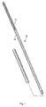
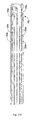
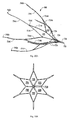
- Figure 1 is a perspective view of a first embodiment of the vein filter of the present invention in the collapsed configuration
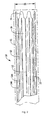
- Figure 2 is an enlarged side view of a portion of the vein filter of Figure 1 ;
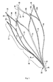
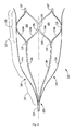
- Figure 3 is a perspective view of the vein filter of Figure 1 in an expanded configuration
- Figure 4A is a side view of the vein filter of Figure 1 in another expanded configuration
- Figure 4B is a front view of the vein filter of Figure 4 in the expanded configuration
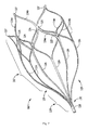
- Figure 5 is a side view of the vein filter of Figure 3 in the expanded configuration
- Figure 6A is a close up view of a portion of the struts showing one embodiment of anchoring elements having pointed ends;
- Figure 6B is a close up view of a portion of one of the struts showing another embodiment of anchoring elements in the form of hemispherical cutouts;
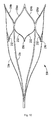
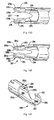
- Figure 7 is a perspective view of an alternate embodiment of the vein filter of the present invention shown in the expanded configuration
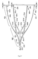
- Figure 8 is a side view of the vein filter of Figure 7 ;
- Figure 9 is a side view of a portion of the vein filter of Figure 7 shown in the collapsed configuration
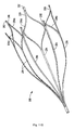
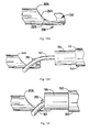
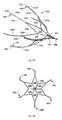
- Figure 10 is a perspective view of another alternate embodiment of the vein filter of the present invention shown in the expanded configuration
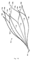
- Figure 11A is a perspective view of yet another alternate embodiment of the vein filter of the present invention shown in the expanded configuration
- Figure 11B is a view similar to Figure 11A showing an alternate embodiment of the hooks
- Figure 11C is a view similar to Figure 11A showing another alternate embodiment of the hooks
- Figure 11D is a view similar to Figure 11A showing yet another alternate embodiment of the filter of the present invention.
- Figure 11E is a perspective view of the filter of Figure 11D in the collapsed position
- Figure 11F is an enlarged view of the retention hooks of Figure 11 D;
- Figure 11G is a perspective view of an alternate embodiment of the filter of Figure 7 having the retention hooks of Figure 11 D;
- Figure 11H is an enlarged view of the retention hooks of Figure 11G in the collapsed position
- Figure 12A is a close up perspective view of an alternate embodiment of an end of the filter having a series of cutouts to receive a retrieval snare;
- Figure 12B is a close up perspective view of an alternate embodiment of an end of the filter having cutouts to receive a retrieval snare;
- Figure 12C is a side view of the embodiment of Figure 12B showing a retrieval snare placed in one of the cutouts between the coils;
- Figure 13A is a close up perspective view of another alternate embodiment of an end of the filter having a hook to receive a retrieval snare;
- Figure 13B is a perspective view of an end of the filter illustrating another alternate embodiment of the hook to receive a retrieval snare;
- Figures 13C and 13D are perspective and top views, respectively, of an alternate embodiment of the hook to receive a retrieval snare;
- Figure 13E is a top view of an alternate embodiment of the hook of Figure 13C ;
- Figures 13F and 13G are perspective and side views, respectively, of another alternate embodiment of the hook to receive a retrieval snare;
- Figures 13H-13J are side views showing the method steps for engaging the hook of Figure 13F for removing the filter utilizing a retrieval snare when the snare approaches from one orientation;
- Figures 13K-13N are side views showing the method steps for engaging the hook of Figure 13F for removing the filter utilizing a retrieval snare when the snare approaches from an orientation opposite the orientation of Figure 13H ;
- Figures 14 , 15 and 16 illustrate delivery and placement of the vessel filter of Figure 1 in the inferior vena cava wherein Figure 14 illustrates initial insertion of the delivery sheath through the femoral vein, Figure 15 illustrates the delivery sheath being advanced toward the inferior vena cava just below (upstream) the juncture of the renal arteries; and Figure 16 illustrates the delivery sheath fully withdrawn to place the filter in the expanded placement configuration in the inferior vena cava;
- Figure 17 is a perspective view of one embodiment of a delivery system for the vein filter
- Figure 18 is an exploded view of the delivery system of Figure 17 ;
- Figure 19 is a cross-sectional view showing the engagement of the interlocking rails of the cartridge with the hub;
- Figure 20A is a perspective view of an alternate embodiment of the filter of the present invention having interconnecting struts in the filter portion, the filter shown in the expanded configuration;
- Figure 20B is a front view of the filter of Figure 20A ;
- Figure 20C is a side view of the filter of Figure 20A ;
- Figure 20D is a perspective view of the filter of Figure 20A shown in the collapsed configuration
- Figure 20E is an enlarged view of an end portion of the filter of Figure 20D showing the retention hooks
- Figure 20F is an enlarged developed view of the end portion of the filter of Figure 20D showing the axial relationship of the retention hooks;
- Figure 21 is a perspective view of another alternate embodiment of the filter having interconnecting struts in the filter portion;
- Figure 22A is a perspective view of another alternate embodiment of the filter of the present invention having interconnecting struts in the filter portion and in the mounting portion;
- Figures 22B and 22C are front and side views, respectively of the filter of Figure 22A ;
- Figure 22D is a perspective view of the filter of Figure 22A shown in the collapsed configuration
- Figure 22E is an enlarged view of an end region of the filter of Figure 22D in the collapsed configuration
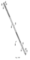
- Figure 23 is a perspective view of another alternate embodiment of the vein filter of the present invention in the collapsed configuration for delivery;
- Figure 24 is a close up perspective view of the retention hooks of the filter of Figure 23 in the collapsed position
- Figure 25 is a perspective view of the vein filter of Figure 23 in the expanded configuration
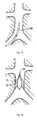
- Figure 26 is a front view of the filter of Figure 25 ;
- Figure 27 is a side view of the filter of Figure 25 showing the axial spacing of the retention hooks.
- Figure 28 is an enlarged developed view of the end portion of the filter of Figure 27 .
- vein filter of the present invention for placement within the inferior vena cava to capture blood clots or other particles which could otherwise pass to the lungs.
- the filter is movable from a low profile collapsed configuration to facilitate insertion through the delivery sheath to a larger expanded placement configuration to enable atraumatic engagement with the vessel walls to secure (mount) the filter within the inferior vena cava.
- the filter is preferably substantially bell-shaped and preferably has a flared or mounting region (portion/section) and a filtering region (portion/section).
- the filtering portion has inwardly directed struts, terminating in a converging region, thereby directing particles toward the central axis of the filter. By directing the particles to the center, they will be exposed to greater blood flow which improves dissolution of the particles.
- the other portion increases in transverse dimension to form a flared region.
- the flare provides less contact area than a straight region, resulting in less tissue ingrowth to facilitate removal of the filter if desired.
- the flare also reduces the chance of vessel distortion if inserted into a curved vena cava.
- the filter is designated generally by reference numeral 10 and is shown in a collapsed configuration for delivery.
- Filter 10 is preferably formed from a single tube 11.
- the filter 10 is composed of shape memory material, such as Nitinol, a nickel titanium alloy, or elgiloy, however, other materials such as stainless steel are also contemplated.
- a plurality of cutouts 12 are formed in the filter 10, preferably by laser cutting although other techniques are contemplated. In the illustrated embodiment, six elongated cutouts are formed, creating six strips or struts 14 of substantially uniform width separated by the cutouts 12 and extending from tubular portion 18.
- the collapsed configuration of filter 10 reduces the overall profile to facilitate delivery to the site.
- the diameter or transverse dimension of filter 10 in the collapsed configuration is represented by reference D1 and preferably is about 2mm and more preferably about 1.7mm. Other dimensions are also contemplated.
- the diameter or transverse dimensions of the filter in the expanded placement configurations e.g. Figs. 4A and 5
- the filter is thus preferably dimensioned for insertion through a 6 French delivery system and through a 6 French catheter.
- FIGS 3-5 illustrate the expanded placement configuration of the filter 10.
- Filter 10 is generally bell-shaped in configuration.
- Filter 10 has a flared region 17 and a converging region 21 at the filtering section 19.
- the transverse dimension of the filter at flared (or mounting/anchoring) region 17 is thus greater than the transverse dimension at filtering section 19.
- the filter can expand to a diameter D2 shown in Figure 5 .
- the filter expands to a smaller diameter, e.g. D3, shown in Figure 4 .
- Diameters (or transverse dimensions) D2-D3 preferably range from about 18 mm to about 32mm, depending on the internal diameter of the vessel wall as will be explained in more detail below. Other dimensions are also contemplated.
- the elongated struts 14 are spaced apart as shown and extend at an angle away from the longitudinal axis L of filter 10 in region 17 to provide a flare. Preferably, this angle or taper is about 10°, although other dimensions are contemplated.
- the struts 14 curve or bend inwardly (region 23) toward the longitudinal axis and then extend inwardly at an angle to the tubular portion 18, thereby forming an angle with the longitudinal axis.
- the six struts 14 when expanded, are shown spaced approximately 60 degrees apart. It is also contemplated that a fewer or greater number of struts could be provided and spacing other than 60 degrees be provided.
- each elongated strut 14 has an outer surface 20 for engagement with the vessel wall to retain the filter 10 in position in the vessel. This region is angled with respect to the longitudinal axis.
- the outer surface 20 of struts 14 could be roughened to enhance engagement.
- a plurality of atraumatic tabs, barbs or other penetrating members can extend from the outer surface 20 of the struts 14 to engage the vessel wall to retain the filter.
- Figures 6A and 6B show examples of such retention features.
- the filter has a series of hemispherical cutouts 152 formed along the length of the struts 154 forming pointed edges 156 to engage the vessel wall.
- the cutouts 152 can be formed along the length of the strut 154 or alternatively be formed only along a portion of the length.
- the cutouts can also be formed on fewer than all the struts.
- the filter has anchoring elements 162 formed by cutouts 163 at the ends of the struts 164.
- Anchoring elements 162 have pointed ends 165. In the collapsed configuration the anchoring elements 162 and their pointed ends 165 are aligned with the struts 164, substantially parallel with the longitudinal axis of the filter to maintain a reduced profile. When the filter moves to the expanded configuration, the pointed ends 165 face outwardly as shown in Figure 6A .
- Anchoring elements 162 can be placed in the end regions of the strut or in other locations. The anchoring elements can also be placed in the opposite direction shown.
- the struts 174 of filter 170 terminate in hooks 172 which extend substantially perpendicular from the strut. Hooks extend from the substantially V-shaped region 179 formed by the joining of connecting struts 174a, 174b.
- struts 184 of filter 180 also terminate in substantially perpendicular hooks 182, however this arrangement is achieved by torquing the connecting struts 184a, 184b at the curved region 185 so the hooks bend out of the plane.
- hooks 182 extend from V-shaped region 189 formed by the connecting struts 184a, 184b.
- the hooks 192 of filter 190 lie in the plane of the connecting struts 194a, 194b, flush with the width surface "w" of the V-shaped region 199 of connecting struts 194a, 194b.
- the hooks 302 lie in the same plane as the connecting struts 304a, 304B of struts 310 as in Figure 11B ; however the hooks of filter 301 are of two different sizes. More specifically, a first set of hooks 302a is larger than a second set of hooks 302b.
- hooks 302a are formed so that they occupy a region equivalent to the transverse dimension of two adjacent struts. For example, in the collapsed configuration, hook 302a occupies a region (dimension) of four connecting struts while smaller hook 302b would only occupy the region (dimension) of two connecting struts.
- Smaller hooks 302b are spaced axially inwardly with respect to larger hooks 302a to minimize the collapsed profile (transverse dimension) of the filter when collapsed for insertion.
- smaller hooks 302b occupy the space created by the larger hooks 302a so they can be considered as nesting within larger hooks 306a.
- each hook 302b has an outer surface 307 which conforms (follows the contour) to an inner surface 309 of a hook 306a.
- hooks 172, 182, 192, 302 can be used with any of the disclosed embodiments (see e.g. Figure 11 G) .
- Such hooks can also be formed or placed on fewer than all the struts.
- the filtering section of filter 10 at a first end of the filter is designated generally by reference numeral 19 and includes the converging region 21.
- Filtering section 19 extends from the flared region 17, and extends toward the central longitudinal axis L of the filter 10 and converges at portion 32 into tubular portion 18.
- struts 14 bend inwardly (region 23), then extend radially inwardly toward the tubular portion 18, and transition to the tubular portion 18.
- the tubular portion 18 and converging region 19 of the filter 10 are spaced both axially outwardly and radially inwardly from the bend regions 23 of the strut 14.
- the filter is designed to direct particles to the center of the filter and vessel. (Trapping the particles at the center rather than the edges of the filter is more desirable because there is less blood flow at the edges of the vessel and greater blood flow at the center to better dissolve the particles.) For clarity, not all of these sections of each strut 14 are labeled in the drawings, it being understood that the non-labeled struts can have the same configurations.
- each strut 14 is divided into two connecting strut portions 14a, 14b.
- each strut portion 14a, 14b is about one half the width of the undivided strut 14, although other widths are contemplated.
- the strut portions 14a, 14b of each divided strut 14 extend in opposite directions and include a curved region 25 as the strut portions 14a, 14b each extend toward respective strut portion 14a or 14b of an adjacent strut. That is, strut portions 14a, 14b form connecting portions to connect adjacent struts 14 as connecting strut 14a of one strut is connected to connecting strut 14b of an adjacent strut.
- strut portion 14a on one strut and portion 14b of another strut converge at end region 29 of the filter and form a substantially V-shaped region.
- Six such V-shaped end portions are preferably formed, each portion connecting adjacent struts. Note that although all six struts 14 are shown interconnected, it is also contemplated that fewer than all the struts can be interconnected.
- the filter 10 can be viewed as having a filtering section 19 at a first end extending from the tubular portion 18.
- each of the struts 14 emerges from the tubular portion 18 at an angle that extends outwardly away from the center to transition to curved portions 23.
- the curved portions 23 extend outwardly away from the longitudinal axis forming a flare or region of progressively increasing transverse dimension.
- the struts 14 are interconnected by connecting struts 14a, 14b that curve inwardly toward the connecting strut 14a or 14b of an adjacent strut to form a substantially V-shaped end portion.
- the filter tube of the embodiments described herein is preferably made of shape memory metal material, such as Nitinol, a nickel titanium alloy.
- shape memory metal material such as Nitinol, a nickel titanium alloy.
- the memorized configuration of the filter 10 is shown in Figure 1 .
- cold saline can be injected into the delivery sheath or catheter 100 and around the filter 10 in its collapsed position within the delivery sheath 100.
- This shape memory material characteristically exhibits rigidity in the austenitic state and more flexibility in the martensitic state.
- the cold saline maintains the temperature dependent filter 10 in a relatively softer condition as it is in the martensitic state within the sheath. This facilitates the exit of filter 10 from the sheath 100 as frictional contact between the filter 10 and the inner surface of the sheath would otherwise occur if the filter was maintained in a rigid, i.e. austenitic, condition.
- the filter is no longer cooled and is exposed to the warmer body temperature, which causes the filter 10 to return towards its austenitic memorized configuration.
- the filter 10 (and other filters described herein) can be inserted through the jugular vein in the neck of the patient or through the femoral vein in the leg of the patient or the arm.
- the filters can also be placed in the superior vena cava.
- Figures 14-16 illustrate delivery and placement of the filter 10, by way of example, in the inferior vena cava.
- Delivery catheter 100 is inserted through the femoral vein "f" and advanced through the iliac arteries into the inferior vena cava. Delivery catheter would be withdrawn once the tip of the sheath is adjacent the structure so that withdrawal of the sheath would place the filter in the desired location of Figure 16 .
- Tubing 104 and valve assembly 106 enable saline injection.
- Delivery catheter 100 is withdrawn to enable filter 10 to be warmed by body temperature to transition to the expanded placement configuration.
- the other filters described herein could be inserted in the same manner. Note it is implanted in the orientation such that filter section 19 is downstream of the flared section 17. This enables blood clots or other particles to be directed to the center of the filter section by the angled struts.
- the direction of insertion e.g. upstream or downstream direction, will determine how the filter is to be positioned in the delivery catheter.
- the strut width can vary.
- the struts can be wider at the flared region than at the filtering portion. This is preferably achieved by removing material to create the thinner portions. These thinner portions increase the flexibility of the filter for forming the angled and curved portions upon deployment.
- the filter can have struts which are thinner, rather than wider, at the flared region, than at the angled and curved regions of the filtering portion. This would provide more stability at the curved regions.
- the adjustment of the widths is designed to strike a balance between stability and flexibility of the various regions of the filter.
- other width variations are contemplated such as making multiple width changes within each strut and/or in different struts.
- FIGS 7-9 illustrate an alternate embodiment of the filter, designated by reference numeral 110.
- Filter 110 is similar to filter 10 except for end region 121. That is, like filter 10, filter 110 has a filtering region 119 which extends from the flared (anchoring/mounting) region 117, and extends toward the central longitudinal axis L of the filter 110 and converges at portion 132 into tubular portion 118. Struts 114 bend inwardly toward the longitudinal axis of the filter 10 at region 123. For clarity, not all of these sections of each strut 114 are labeled in the drawing, it being understood that the non-labeled struts can have the same configurations.
- the flared region 117 as in filter 10 is of an angle preferably about 8 degrees although other angles are contemplated.
- the end region 121 of filter 110 where the struts 114 interconnect differs from filter 10.
- the struts 114 are interconnected by connecting strut portions 114a, 114b that curve outwardly away from the central axis and then inwardly toward each other to form a substantially V-shaped end portion 127.
- the connecting struts are joined to connecting struts of adjacent struts 114 (region 125).
- a closed geometric shape 133 is formed as shown.
- the closed shape as shown is substantially oval in configuration, although other shapes are contemplated.
- each connecting adjacent struts six such closed geometric shapes are preferably formed, each connecting adjacent struts, although fewer closed shapes are contemplated if fewer than all the struts are interconnected. Also, the length of the region 125 where the struts are joined can be shorter or longer than that shown, thereby changing the configuration of the closed geometric shape (e.g. making it longer or shorter).
- each strut 114 divides into two connecting strut portions 114a, 114b which initially extend outwardly from each other. As each strut extends outwardly, the strut portion 114a joins the strut portion 114b of an adjacent strut at region 125. After this joined region 125, the strut portions 114a and 114b which emanate from the same strut extend inwardly towards each other and are joined at their ends into a substantially V-shaped end, designated by reference numeral 127.
- FIG. 9 The collapsed configuration of filter 110 is shown in Figure 9 with cutouts 112 forming six struts 114. Regions 113 illustrate where struts 114 divide.
- filter 150 resembles filter 10 of Figure 1 except for the additional connecting struts or ribs 152.
- These ribs increase the stability of the filter 150.
- the two ribs 152 extend from adjacent struts 154 and curve inwardly towards each other and are joined at region 156 (forming a V-like connection).
- the ribs 152 can be arranged so they are axially aligned as in Figure 10 or alternatively can be staggered i.e. spaced axially (not shown).
- the ribs can be placed between fewer than all the struts and the ribs can be utilized with any of the foregoing embodiments.
- Struts 154 divide into connecting struts 154a, 154b in the embodiment of Figure 1 .
- FIGS 11G and 11H illustrate an alternate embodiment of the filter of Figure 7 having the hooks of filter 301 of Figure 11D .
- Filter 350 like filter 110, has struts 354 which are interconnected by connecting strut portions 354a, 354b that curve outwardly then inwardly toward each other to form V-shaped portions 357, terminating in hooks 356.
- large hooks 356a alternate with axially offset smaller hooks 356b and are identical to hooks 306a, 306b of Figure 11D .
- the ribs could curve radially outward near their tips, thus contacting the vessel wall and acting as a retaining mechanism.
- FIG 20A illustrates an alternate embodiment of the filter of the present invention.
- the struts are interconnected at the filtering region rather than at the flared mounting (anchoring) region. This creates closed geometric shapes at the filtering region to enhance the clot capturing capability of the filter. Also, by providing the interconnection more forward (downstream) in the filter, i.e. in the filtering region (filtration zone), linear movement of the filter is facilitated to enhance removal of the filter.
- bell-shaped filter 700 has a filtering region 719 and a flared anchoring (mounting) region 721 of greater transverse dimension. Flared region 721 is preferably at an angle of about 8 degrees to about 14 degrees with respect to the longitudinal axis of the filter, although other angles are contemplated. In this flared region 721, the transverse dimension increases towards the anchoring end of the filter 700 so that as in the other embodiments disclosed herein, the terminal end of the filter at region 719 has a smaller transverse dimension than at the opposing terminal end at region 721.
- the filtering region 719 extends from the flared region 721 toward the longitudinal axis of the filter 700 and converges at portion 732 into tubular portion 718 at the filter end portion of filter 700.
- Filtering region 719 has six struts 714 curving outwardly from tubular portion 718.
- Each filter strut or strut portion 714 extends radially from tubular portion 718 and divides into two connecting filter struts or strut portions 714a, 714b (preferably of equal width) that angle way from each other (in different directions) to extend to the connecting strut portion of an adjacent strut 714.
- connecting strut portion 714a of one strut 714 interconnects with the connecting strut portion 714b of an adjacent strut at joining region 714d.
- struts 714 divide into connecting struts 714a, 714b of half the width, other dimensions are contemplated.
- strut portions 714a, 714b After convergence of strut portions 714a, 714b at joining region 714d, it transitions into elongated mounting strut portions 714c which form flared mounting or anchoring region 721.
- the length of the strut portions 714c in the anchoring region 721 can vary, with increased/decreased length increasing the flexibility/rigidity of the struts.
- the thickness of the strut portions can also vary to affect flexibility/rigidity.
- the strut portions 714c terminate in hooks 740a, 740b similar to hooks 302a, 302b of Figure 11D . That is, hooks 740a and 740b lie in the plane of the struts 714c and hooks 740a are larger than hooks 740b, formed so they occupy a region equivalent to the transverse dimension of two adjacent struts. Smaller hooks 740b nest within larger hooks 740a as described above in conjunction with hooks 302a, 302b.
- hooks 740b are spaced axially (inwardly) of hooks 740a as well as spaced axially with respect to each other as represented by the arrows in Figure 20F designating the three different distances E1, E2 and E3 in the developed view, presented for ease of understanding since the hooks are formed from a tube.
- Other hook designs could alternatively be provided, including the various hook embodiments described herein.
- the tubular portion 718 is preferably in the form of a retrieval hook as described herein with respect to the other embodiments, and preferably in the form of retrieval hook 290 of Figure 13F .
- Other retrieval structure can also be utilized.
- the filter is designated generally by reference numeral 800 and has a filtering region 819 and a flared anchoring (mounting) region 821.
- the filter 800 differs from filter 700 in the additional joining regions of the connecting struts. More specifically, filter struts 814 extend radially from tubular portion 818, in a similar manner as struts 714 of Figure 20A . Struts 814 divide into connecting struts or strut portions 814a, 814b, extending in different directions, and then join at first joining regions 814c to a connecting strut of an adjacent strut 814.
- connecting struts or strut portions 814f, 814g extend in different directions, away from each other, to connect to another adjacent strut 814f or 814g at second joining regions 814d.
- the mounting struts or strut portions 814h extend longitudinally to form the flared mounting or anchoring region 821.
- the interconnecting struts preferably form a first set of substantially diamond shaped closed geometric shapes 830 as shown and a second set of substantially hexagonal shaped closed geometric shapes 832. Other shapes are contemplated as are a different number of struts 814, interconnecting struts, and closed geometric shapes. For clarity, not all identical parts are labeled in the drawings.
- hooks 840a, 840b as shown are identical to hooks 740a, 740b of Figure 20 .
- Retrieval hook 850 at the tubular end portion 818 of the filtering end portion of filter 800 is preferably identical to retrieval hook 750 of filter 700.
- Other hook designs and retrieval structure could alternatively be utilized.
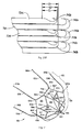
- FIGS 23-28 illustrate an alternate embodiment of the filter of the present invention, designated generally by reference numeral 1010.
- Filter 1010 is substantially identical to filter 700 of Figures 20A-20E except for the retention hooks.
- Filter 1010 has struts interconnected in the filtering region and not in the flared mounting (anchoring) region as in filter 700. This creates closed geometric shapes at the filtering region to enhance the clot capturing capability of the filter.
- the mounting region is devoid of such closed geometric shapes as it is devoid of interconnecting or connecting struts. This facilitates removal.
- Filter 1010 is substantially bell shaped and has a filtering region 1012 and a flared anchoring (mounting) region 1024 of greater transverse dimension. Flared region 1024 is preferably at an angle of about 8 degrees with respect to the longitudinal axis of the filter, although other angles are contemplated. In this flared region 1024, the transverse dimension increases towards the anchoring end of the filter 1010 so that as in the other embodiments disclosed herein, the terminal end of the filter at region 1019 has a smaller transverse dimension than at the opposing terminal end at region 1021.
- the filtering region 1012 extends from the flared region 1024 toward the longitudinal axis of the filter 1010 and converges at portion 1022 into tubular portion 1018 at the filter end portion of filter 1010.
- Filtering region 1019 preferably has six struts 1014 curving outwardly from tubular portion 1018.
- Each filter strut or strut portion 1014 extends radially from tubular portion 1018 and divides into two connecting (interconnecting) filter struts or strut portions 1014a, 1014b (preferably of equal width) that angle way from each other (in different directions) to extend to the connecting strut portion of an adjacent strut 1014.
- connecting strut portion 1014a of one strut 1014 interconnects with the connecting strut portion 1014b of an adjacent strut at joining region 1014d.
- This forms closed geometric shapes 1025 preferably substantially diamond shaped in configuration, although other shapes are contemplated.
- struts 1014 divide into connecting struts 1014a, 1014b of half the width, other dimensions are contemplated.
- strut portions 1014a, 1014b After convergence of strut portions 1014a, 1014b at joining region 1014d, it transitions into elongated mounting strut portions 1014c which form flared mounting or anchoring region 1024.
- the length of the strut portions 1014c in the anchoring region 1024 can vary, with increased/decreased length increasing the flexibility/rigidity of the struts.
- the thickness of the strut portions can also vary to affect flexibility/rigidity.
- the strut portions 1014c terminate in hook portions 1030.
- Hook portions 1030 in this embodiment are preferably of substantially the same size.
- the hook portions or the struts from which they extend have different lengths so that the distalmost end of the hook portions 1030 terminate at different axial positions.
- the hooks are staggered in an axial direction so the struts terminate at different points.
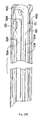
- Figure 28 illustrates the six different distances, in the developed view, presented for ease of understanding since the hooks are formed from a tube.
- Hook portions 1030 lie in the plane of a distal portion 1014d of the struts 1014c. That is, the distal portion 1014d of the strut 1014c twists out of the plane of the remaining portion of the strut, with the hooks lying in the plane of the distal portion.
- Hook portions 1030 includes a hook 1032 having a penetrating tip 1034 preferably pointing toward a proximal portion (filter region) of the filter 1010.
- a top wall 1036 of the hook 1032 has a slight step 1038.
- the penetrating tip 1034 extends about a curved wall 1039.
- the penetrating tip 1034 in the illustrated embodiment extends substantially parallel to a longitudinal axis L1 of the struts portion 1050.
- a plurality of teeth 1040 Opposite the curved wall 1039 on hook 1032 are a plurality of teeth 1040, with points or edges facing in a distal direction, opposite the direction of the penetrating tip 1034. Teeth 1040 engage the vessel wall to provide additional retention to prevent movement of the implanted filter in the caudal direction.
- a heel 1044 is formed on a distal end of the hook portion 1030, terminating in a curved surface 1046 and extending distally beyond the hook 1032. Heel 1044 extends past the hook 1032 to function as a stop to prevent the filter strut portions from going through the vessel wall.
- Hook portion 1030 also has a reduced width dimension Z1 which transition from the strut 1014d to the hook 1032. For clarity, only some of the hooks and hook portions are labeled in Figure 28 .
- hook portions 1030 somewhat nest within an adjacent hook portion. More specifically, the strut of portion 1030 has a reduced area 1049 (with width dimension Z1) which forms a gap 1045 to receive a portion of heel 1044 of an adjacent hook portion 1030. In this configuration, a portion of the heel 1044 of the hook portion 1030 is in general longitudinal alignment with a penetrating tip 1034 of an adjacent hook as described below.
- the strut 1014d at the reduced area portion 1049 has a first wall 1052 and a second wall 1054 forming a width Z1 defined as the distance or space between the walls 1052, 1054.
- the strut 1014d adjacent the reduced area 1049 has a first wall 1056 and a second wall 1058, forming a width Z2, defined as the distance or space between walls 1056, 1058.
- Line S1 represents this first wall 1056 of strut 1014d.
- the hook 1032 has a height Z3 greater than height Z2 such that it extends widthwise beyond the height of the first wall 1052.
- the penetrating tip 1034 extends radially beyond the Line S1, illustrated by line S2 (extrapolated from the perpetrating tip 1034).
- width Z1 could be between about .013 inches (about 0.33 mm) to about .019 inches (about 0.48 mm), and preferably about .016 inches (about 0.41 mm)
- width Z2 could be between about .025 inches (about 0.64 mm) to about .035 inches (about 0.89 mm), and preferably about .030 inches (about 0.76 mm)
- width Z3 could be about .035 inches (about 0.89 mm) to about .045 inches (about 1.14 mm), and preferably about .040 inches (about 1.02 mm)
- width Z4 at the heel 1044 could be between about .011 inches (about 0.28 mm) to about .017 inches (about 0.43 mm), and preferably about .014 inches (about 0.36 mm). It should be understood that other dimensions are also contemplated.
- Line S3 represents the second wall 1058 extrapolated in a proximal direction.
- the heel 1044 extends widthwise beyond the line S3 and width of the second wall 1054.
- Wall 1058 also includes a slight indentation 1055 to accommodate the penetrating tip portion 1034 of the adjacent hook 1032.
- the tubular portion 1018 is preferably in the form of a retrieval hook as described herein with respect to the other embodiments, and preferably in the form of retrieval hook 290 of Figure 13F .
- Other retrieval structure can also be utilized.
- FIG 22 illustrates an alternate embodiment of the filter of the present invention.
- the struts are interconnected at the filtering region (filtration zone) and at the flared mounting (anchoring) region. These interconnecting struts at the filtering region enhance the clot capturing capability of the filter.
- the interconnection at the mounting region enhances the stability of the filter and the vessel retention capability by reducing the flexibility of the struts.
- bell-shaped filter 900 has a filtering region 919 and a flared anchoring (mounting) region 921 of greater transverse dimension.
- Flared region 921 is preferably at an angle of about 8 degrees with respect to the longitudinal axis of the filter, although other angles are contemplated.
- the transverse dimension increases towards the anchoring end of the filter 900 so the terminal end of the filter at region 919 has a smaller transverse dimension than the opposing terminal end at region 921.
- the filtering region 919 extends from the flared region 921 toward the longitudinal axis of the filter 900 and converges at portion 932 into tubular portion 918 at the filter end portion of filter 900.
- Filtering region 919 has six struts 914 curving outwardly from tubular portion 918.
- Each elongated filter strut or strut portion 914 extends radially from tubular portion 918 and divides into two connecting filter struts or strut portions 914a, 914b (preferably of equal width) that angle way from each other (in different directions) to extend to the connecting strut portion of an adjacent strut 914.
- connecting strut portion 914a of one strut 914 interconnects with the connecting strut portion 914b of an adjacent strut at joining region 914d.
- struts 914 can divide into connecting struts 914a, 914b of half the width, other dimensions are contemplated such as equal to the width.
- each strut 914c divides into two connecting mounting strut portions 914e, 914f.
- Each strut portion 914e, 914f can be one half the width of the undivided strut 14, although other widths are contemplated such as equal to the width.
- each divided strut 914c extend in opposite directions and include a curved region as the strut portions 914e, 914f each extend toward respective strut portion 914e or 914f of an adjacent strut. That is, strut portions 914e, 914f form connecting portions to connect adjacent struts 914c as connecting strut 914e of one strut is connected to connecting strut 914f of an adjacent strut. Connecting strut portion 914e on one strut and portion 914f of another strut converge at end (joining) region 929, as closed geometric shapes 935 are formed.
- End region 929 has an elongated region (or hook strut) 931 and preferably terminates in hooks described below. Note that although all six mounting struts 914 are shown interconnected, it is also contemplated that fewer than all the struts can be interconnected.
- the elongated struts have a first angled region of interconnecting (connecting) struts 914a, 914b in the filtering region 919 and a second angled region of interconnecting (connecting) struts 914e, 914f in the mounting region 921.
- the region of the interconnecting struts in the first region has a transverse dimension less than the transverse dimension of the region having the interconnecting struts in the mounting region.
- the filter strut portions and mounting strut portions each divide into connecting struts of half the width.
- the filter struts and mounting struts are also bifurcated, however the width of the connecting strut is increased so it is greater than one half the width of the struts and can for instance be equal to the width of the strut.
- Such bifurcation with increased width is also applicable to the other embodiments of the filter described herein. Bifurcation with decreased width is also contemplated.
- the strut portions 914c terminate in hooks 940a, 940b similar to hooks 302a, 302b of Figure 11D . That is, hooks 940a and 940b lie in the plane of the struts 914 and hooks 940a are larger than hooks 940b, formed so they occupy a region equivalent to the transverse dimension of two adjacent struts. Smaller hooks 940b nest within larger hooks 940a in the same manner as described above in conjunction with hooks 302a, 302b.
- hooks 940b are spaced axially (inwardly) of hooks 940a as well as spaced axially with respect to each other in the same manner as described with respect to hooks 740b of filter 700 and illustrated in Figure 20F showing the three different distances E1, E2 and E3 in the developed view.
- Other hook designs could alternatively be provided, including the various hook embodiments described herein.
- the tubular portion 918 is preferably in the form of a retrieval hook 950 as described herein with respect to the other embodiments, and preferably in the form of retrieval hook 290 of Figure 13F .
- Other retrieval structure can also be utilized.
- Filters 700, 800 and 900 are preferably manufactured from a cut tube, preferably laser cut. Therefore, as in the other embodiments described herein, terms such as interconnected, connected, joined, etc., are used for ease of description, it being understood that preferably these portions are integral as they are preferably formed from a single tube. Also, mounting struts and filter struts used to describe the various embodiments disclosed herein can be considered as mounting strut "portions” or “sections” and filter strut "portions" or “sections” of the same struts if the filter is formed integrally, e.g. from a cut tube.
- the foregoing filters can be inserted through the femoral vein or alternatively through the internal jugular vein. It can be removed from access through the internal jugular vein or femoral vein.
- Various methods can be used to remove the filter such as those described in commonly assigned co-pending application serial no. 09/911,097, filed July 23, 2001 , now published application 2002-0193827-A1, published December 19, 2001 , the entire contents of which is incorporated herein by reference, including for example, slotted hooks, graspers, etc.
- a recess or cutout can also be provided at the tubular end portions to receive a snare or other device for removal.
- a hook 222 at tubular portion 220 is illustrated in the embodiment of Figure 13A and is configured to receive a snare.
- FIG. 13B illustrates another embodiment of a hook.
- Hook 232 formed in tubular portion 230 forms a cutout 234 for receiving a snare or other removal device.
- the snare can surround and grasp both ears 235.
- the gap 237 between the ears 235 also enables a retrieval snare to lie in the gap 237 to surround and grasp one of the two ears 235.
- hook 272 is similar to hook 232 of Figure 13B in that it has two ears 275 with a gap 277 therebetween. However it differs in that it has a bottom cutout 278 formed between walls 279. It also differs in that surfaces 274 of ears 275 are rounded and outer proximal walls 278a angle outwardly (proximally) to curved peak 276 then angle inwardly (wall 278b) to provide a smoother transition into the retrieval sheath. Thus, two angled transitions are provided.
- the side walls 284 extending into ears 285 of hook 282 angle inwardly toward the longitudinal axis. Consequently, there are three angled transitions: 1) an angled transition in a first direction formed by angled walls 288a which angle proximally outwardly from the edge 285a of ears 285 to the curved peak 285b (the proximal end of the hook is designated generally by reference numeral 283); 2) an angled transition in a second direction formed by angled walls 288b which angle distally outwardly from curved peak 285b; and 3) an angled transition formed by walls 284 which angle proximally inwardly as walls 284 come closer together toward the proximal end.
- FIGs 13F and 13G illustrate another alternate embodiment of the retrieval hook of the present invention.
- This is the retrieval hook shown in conjunction with filter 301 of the embodiment of Figures 11D and 11G .
- Hook 290 has a curved hook 292 at the proximalmost end.
- This hook 292 is configured to receive a retrieval snare or other retrieval device.
- a portion of the wall of the hook 290 is cut out to expose the annular interior surface 294. That is, being formed from a laser cut tube, a wall portion is removed to expose curved inner wall surface 294.
- This annular interior surface 294 extends from radiused region 295 to proximalmost edge 296.
- the interior surface 294 can be considered to have an interior surface 294a at the radiused region 295 and an interior surface 295b at the hook 292.
- the interior surface 294b accommodates a portion of a tubular snare sheath. That is, the outer wall of the snare sheath (tube) can partially fit within the cut out region 293. This enhances removal as the snare pulls the filter hook into collinear arrangement with the sheath tube.
- the radiused region 295 spaced axially (distal) from the hook 292, includes a radiused or curved edge defined by radiused side walls 297a, 297c and top wall 297b.
- the angled side walls 297a, 297c form camming surfaces to direct the hook 290 and filter into the retrieval sheath. This can be appreciated by reference to Figures 13K-13N discussed below.
- the hook can be formed in other ways to provide an interior annular surface to function in a similar manner as surface 294, i.e. to receive the snare tube.
- retrieval hooks can be used with any of the filters described herein.
- the snare 502 is part of a retrieval system which includes a snare sheath or tube 504 through which the snare 502 extends.
- the distal wall 503 of snare sheath 504 provides for cinching of the snare 502.
- the snare sheath 504 is inserted through retrieval sheath 510. When the filter is pulled into the retrieval sheath 510 it is collapsed for removal.
- preferably cold saline is injected during the removal process to cool the sheath to transition to a softer martensitic state to facilitate removal.
- the snare sheath 504 fits into the cut out region 293 as its outer wall conforms to the inner wall surface 294b of hook 292.
- the hook 290 and snare sheath 504 become substantially collinear as shown in Figure 13I .
- This collinear arrangement facilitates retraction into the retrieval sheath 510 as it reduces the likelihood of a wall of the hook getting caught on the distal edge 512 of the retrieval sheath 510, thus providing a smoother transition into the sheath as shown in Figure 13J .
- Figures 13K-13N illustrate the retrieval steps when the snare approaches from the opposite orientation of Figure 13H , i.e. below the hook as viewed in the orientation of Figure 13K .
- the wall 297b contacts the edge 512 of retrieval sheath 510 and due to the radiused walls 297a, 297c (depending on the side of contact), the hook is cammed downwardly (in the orientation of Figure 13M ) into the retrieval sheath 510 as shown in Figure 13N .
- This provides a smooth transition into the retrieval sheath 510 as it reduces the likelihood of the hook being caught on the sheath edge.
- Figure 12A illustrates another embodiment having a series of recesses 210 along the length of the tubular portion 212. This enables the tubular portion 212 to be grasped at several locations along its length, facilitating grasping of the filter for removal. These multiple recesses or cutouts 210 are axially spaced as shown.
- the end of the tubular portion 240 has a series of axially spaced cutouts 242 which form a coil-like engagement structure.
- This engagement structure provides multiple engagement areas for a retrieval (removal) device, such as a retrieval snare, for grasping the filter as the device can for instance be cinched in any of the spaces (formed by the cutouts) between the turns 246 in the helical coil.
- Figure 12C shows a snare 300 placed in one of the cutouts 242.
- cold saline can be injected onto the implanted filter to change the temperature of the filter to move it to a relatively softer condition to facilitate the filter being drawn in to the retrieval sheath. That is, injection of cold saline will cause the filter to approach its martensitic state, bringing the filter to a more flexible condition.
- the flexible condition facilitates the collapse and withdrawal of the filter into the retrieval sheath, by decreasing the frictional contact between the filter and the inner surface of the retrieval sheath.
- the delivery system 600 includes a hub 602, a cartridge 604 containing the filter, a pusher 606 and a wire 608 extending through the pusher 606.
- the wire 608 extends through the cartridge 604 and through the length of tube 603 to maintain a separation of the hooks, e.g. hooks 402 of filter 350 of Figure 11G , during insertion of the delivery system and delivery of the filter.
- the cartridge 604 is removably attached to the hub 602, preferably by a snap-fit although other modes of attachment are also contemplated.
- the cartridge preferably has markings (not shown) on the outer surface to indicate a femoral or jugular direction so the user knows the orientation to attach the cartridge 604 to hub 602.
- advancement of the pusher 604 advances the filter from the cartridge and through tube 603 as the distal edge of the pusher 604 abuts the proximal end of the filter, with the wire 608 (e.g., a Nitinol wire) preventing entanglement of the retention hooks.
- the wire 608 also provides support (stability) for the pusher 604 as the pusher 604 is advanced over the wire 608.
- the filter is forced out of the distal end of the tube, where it is no longer cooled by saline and is warmed by body temperature to return toward its memorized configuration.
- a locking mechanism can be provided such as the mechanism of Figure 19 .
- the cartridge 604 has a pair of locking rails 612a, 612b, each including a respective recess 614a, 614b.
- the hub 602 contains a detent 620 as shown.
- the recess 614a of the locking rails 612a is retained by the detent 620. This locks the cartridge 604 to the hub 602 during use, preventing unwanted separation of the cartridge 604 from the hub 602. If access via the jugular artery instead of the femoral artery is desired, then the cartridge is inserted so that recess 614b of rail 612b engages detent 620 of hub 602.
- the filters can be inserted in other regions of the body.
- any of the aforedescribed filters can have mounting sections of varying thickness.
- the foregoing filters can be made of materials other than shape memory material.
- a vessel filter comprising a first region and a second region, the filter movable between a collapsed position for delivery to the vessel and an expanded position for placement within the vessel, the first region having a filter portion having a converging region to direct particles toward the center of the filter, the first region including a plurality of spaced apart filter struts, the struts each having a strut width defined as a distance between a first wall and a second wall, and the strut having a longitudinal axis, a plurality of hooks at the second region, the hooks having a vessel penetrating tip, the hooks positioned on a distal end portion of the strut, and having a width greater than the width of the strut from which it extends radially such that the penetrating tip of the hook extends beyond the first wall.
- the vessel filter as described in A further comprising connecting filter struts extending at an angle from the filter struts to join adjacent filter struts.
- a vessel filter comprising a body made from a single tube, the tube cut to create a plurality of elongated struts forming a filter region and a mounting region having a greater transverse dimension than a transverse dimension of the filter region, the mounting region including a plurality of vessel engaging hooks, the hooks having a penetrating tip pointing in a direction toward the filter region, a plurality of teeth for engaging the vessel, and a heel extending beyond the teeth in a direction opposite the direction of the penetrating tip.
- a vessel filter comprising a first region and a second region, the filter movable between a collapsed position for delivery to the vessel and an expanded position for placement within the vessel, the first region having a filter portion having a converging region to direct particles toward the center of the filter, the first region including a plurality of spaced apart filter struts, the struts each having a first width defined as a distance between a first wall and a second wall and having a longitudinal axis, a plurality of hooks at the second region, the hooks having a vessel penetrating tip and a heel, the penetrating tip of one hook longitudinally aligned with a portion of the heel of an adjacent hook.
- T The vessel filter as described in S, wherein the penetrating tip of the hooks points in a proximal direction toward the first region.
- V The vessel engaging hook as described in O wherein the heel extends at an angle to the longitudinal axis.
Abstract
Description
- This application is continuation in part of application serial no.
11/978,821, filed October 30, 2007 10/889,429 filed on July 12, 2004 U.S. Patent No. 7,704,266 , which claims priority from provisional application serial no.60/572,274 filed May 18, 2004 10/805,796 filed on March 22, 2004 U.S. Patent 7,338,512 which claims priority from provisional application serial no.60/538,379, filed January 22, 2004 11/801,547, filed on May 10, 2007 60/818,202 filed on June 30, 2006 10/899,429 - This application relates to a vascular filter and more particularly to a vein filter for capturing blood clots within the vessel.
- Passage of blood clots to the lungs is known as pulmonary embolism. These clots typically originate in the veins of the lower limbs and can migrate through the vascular system to the lungs where they can obstruct blood flow and therefore interfere with oxygenation of the blood. Pulmonary embolisms can also cause shock and even death.
- In some instances, blood thinning medication, e.g. anticoagulants such as Heparin, or sodium warfarin can be given to the patient. These medications, however, have limited use since they may not be able to be administered to patients after surgery or stroke or given to patients with high risk of internal bleeding. Also, this medication approach is not always effective in preventing recurring blood clots.
- Therefore, surgical methods to reduce the likelihood of such pulmonary embolisms by actually blocking the blood clot from reaching the lungs have been developed. One surgical method of treatment involved major surgery where the size of the vessel lumen was restricted by placement of ligatures or clips around the vein, e.g. the inferior vena cava which transports blood from the lower portion of the body to the heart and lungs. This prevented passage of dangerously large blood clots through the vein to the lungs. However, this approach is an invasive surgical procedure, requiring an abdominal incision and general anesthesia and frequently causing vessel thrombosis and lower extremity swelling. Also, there is a lengthy patient recovery time and additional hospital and surgeon expenses associated with this major surgery. In fact, oftentimes, the patients requiring the surgery are unhealthy and the major surgery and general anesthesia poses a risk in and of itself.
- To avoid such invasive surgery, less invasive surgical techniques have been developed. These involve the placement of a mechanical barrier in the inferior vena cava. These barriers are in the form of filters and are typically inserted through either the femoral vein in the patient's leg or the right jugular vein in the patient's neck or arm under local anesthesia. The filters are then advanced intravascularly to the inferior vena cava where they are expanded to block migration of the blood clots from the lower portion of the body to the heart and lungs.
- These prior filters take various forms. One type of filter is composed of coiled wires such as disclosed in
U.S. Patent nos. 5,893,869 and6,059,825 . Another type of filter consists of legs with free ends having anchors for embedding in the vessel wall to hold the filter. These filters are disclosed, for example, inU.S. Patent nos. 4,688,553 ,4,781,173 ,4,832,055 , and5,059,205 ,5,984,947 and6,007,558 . Another type of filter is disclosed inU.S. Patent no. 6,214,025 consisting of wires twisted together to form a cylindrical anchoring portion conforming to the inner vessel wall surface to exert a radial force and a conical filtering portion. - Several factors have to be considered in designing vein filters. One factor is that the filter needs to be securely anchored within the vessel wall, while avoiding traumatic engagement and damage to the wall as well as damage to the neighboring abdominal aorta. Another factor is that the filter must be collapsible to a sufficiently small size to be easily maneuvered and atraumatically advanced intravascularly to the inferior vena cava or other target vessel. Thirdly, the filter should direct the blood clots to the center of the vessel to improve dissolution of the clot within the vessel by the blood flow.
- It would be advantageous to provide a vein filter that satisfies the foregoing parameters. Namely, such vein filter would advantageously have sufficient anchoring force to retain the filter within the vessel while providing atraumatic contact with the vessel wall, would have a minimized insertion (collapsed) profile to facilitate delivery through the vascular system to the surgical site, and would enable migration of the captured blood clots to the center of the vessel. Moreover, it would also be advantageous to provide a filter that could simplify insertion through the femoral or the right jugular vein or arm into the inferior vena cava.
- Additionally, the need for a vein filter in many patients is temporary. In these instances it would be advantageous to provide a vein filter that satisfies the foregoing factors and in addition could be readily removed from the patient. Thus, the filter would advantageously strike the balance of having structure to provide sufficient anchoring while enabling atraumatic removal from the vessel after a period of time. It would further be advantageous if the filter could be removed minimally invasively, e.g. intravascularly.
- According to the present invention there is provided a vessel filter comprising a first region and a second region, the filter movable between a collapsed position for delivery to the vessel and an expanded position for placement within the vessel, the first region having a filter portion having a converging region to direct particles toward the center of the filter, the first region including a plurality of spaced apart filter struts, the struts each having a plurality of hooks at the second region, the hooks having a vessel penetrating tip and a heel, the penetrating tip of one hook longitudinally aligned in the collapsed position with a portion of the heel of an adjacent hook.
- The struts may each have a first width defined as a distance between a first wall and a second wall, and wherein the width of the hook is greater than the first width of the strut from which it extends such that the penetrating tip portion of the hook extends radially beyond the first wall.
- The heel of the hooks may extend radially beyond the second wall of the strut.
- Each of the struts may have a reduced cross-sectional area portion extending longitudinally along the strut and transitioning into the hook, the reduced cross-sectional area portion providing a space to accommodate the heel of an adjacent hook.
- The penetrating tip of the hooks may point in a proximal direction toward the first region and the heel may extend in an opposite direction.
- The heel of the hooks may have a third width less than the first width of the respective strut.
- The heel may extend at an angle to the longitudinal axis of a strut portion.
- A portion of the hook remote from the strut may be axially aligned with an inward curve in a wall of an adjacent hook portion.
- A portion of the hook remote from the strut may have a stepped surface, and the hooks may have a curved end surface.
- The hook may include a series of teeth, and one of the teeth may be substantially aligned with an axis passing through a penetrating tip of the hook.
- The teeth may extend from a non-linear surface.
- The heel may terminate in a curved surface, and a portion of the curved surface may be longitudinally aligned with the second wall of the strut.
- The hooks may include a plurality of teeth, the penetrating tip extending in a first proximal direction toward the first region and the teeth extending in a second different distal direction, the penetrating tip and teeth preventing movement of the filter in opposing directions.
- An end of the penetrating tip may extend substantially parallel to the longitudinal axis of the strut.
- The heels of adjacent vessel engaging hooks may terminate axially spaced.
- Preferred embodiment(s) of the present disclosure are described herein with reference to the drawings wherein:
-
Figure 1 is a perspective view of a first embodiment of the vein filter of the present invention in the collapsed configuration; -
Figure 2 is an enlarged side view of a portion of the vein filter ofFigure 1 ; -
Figure 3 is a perspective view of the vein filter ofFigure 1 in an expanded configuration; -
Figure 4A is a side view of the vein filter ofFigure 1 in another expanded configuration; -
Figure 4B is a front view of the vein filter ofFigure 4 in the expanded configuration; -
Figure 5 is a side view of the vein filter ofFigure 3 in the expanded configuration; -
Figure 6A is a close up view of a portion of the struts showing one embodiment of anchoring elements having pointed ends; -
Figure 6B is a close up view of a portion of one of the struts showing another embodiment of anchoring elements in the form of hemispherical cutouts; -
Figure 7 is a perspective view of an alternate embodiment of the vein filter of the present invention shown in the expanded configuration; -
Figure 8 is a side view of the vein filter ofFigure 7 ; -
Figure 9 is a side view of a portion of the vein filter ofFigure 7 shown in the collapsed configuration; -
Figure 10 is a perspective view of another alternate embodiment of the vein filter of the present invention shown in the expanded configuration; -
Figure 11A is a perspective view of yet another alternate embodiment of the vein filter of the present invention shown in the expanded configuration; -
Figure 11B is a view similar toFigure 11A showing an alternate embodiment of the hooks; -
Figure 11C is a view similar toFigure 11A showing another alternate embodiment of the hooks; -
Figure 11D is a view similar toFigure 11A showing yet another alternate embodiment of the filter of the present invention; -
Figure 11E is a perspective view of the filter ofFigure 11D in the collapsed position; -
Figure 11F is an enlarged view of the retention hooks ofFigure 11 D; -
Figure 11G is a perspective view of an alternate embodiment of the filter ofFigure 7 having the retention hooks ofFigure 11 D; -
Figure 11H is an enlarged view of the retention hooks ofFigure 11G in the collapsed position; -
Figure 12A is a close up perspective view of an alternate embodiment of an end of the filter having a series of cutouts to receive a retrieval snare; -
Figure 12B is a close up perspective view of an alternate embodiment of an end of the filter having cutouts to receive a retrieval snare; -
Figure 12C is a side view of the embodiment ofFigure 12B showing a retrieval snare placed in one of the cutouts between the coils; -
Figure 13A is a close up perspective view of another alternate embodiment of an end of the filter having a hook to receive a retrieval snare; -
Figure 13B is a perspective view of an end of the filter illustrating another alternate embodiment of the hook to receive a retrieval snare; -
Figures 13C and13D are perspective and top views, respectively, of an alternate embodiment of the hook to receive a retrieval snare; -
Figure 13E is a top view of an alternate embodiment of the hook ofFigure 13C ; -
Figures 13F and13G are perspective and side views, respectively, of another alternate embodiment of the hook to receive a retrieval snare; -
Figures 13H-13J are side views showing the method steps for engaging the hook ofFigure 13F for removing the filter utilizing a retrieval snare when the snare approaches from one orientation; -
Figures 13K-13N are side views showing the method steps for engaging the hook ofFigure 13F for removing the filter utilizing a retrieval snare when the snare approaches from an orientation opposite the orientation ofFigure 13H ; -
Figures 14 ,15 and 16 illustrate delivery and placement of the vessel filter ofFigure 1 in the inferior vena cava whereinFigure 14 illustrates initial insertion of the delivery sheath through the femoral vein,Figure 15 illustrates the delivery sheath being advanced toward the inferior vena cava just below (upstream) the juncture of the renal arteries; andFigure 16 illustrates the delivery sheath fully withdrawn to place the filter in the expanded placement configuration in the inferior vena cava; -
Figure 17 is a perspective view of one embodiment of a delivery system for the vein filter; -
Figure 18 is an exploded view of the delivery system ofFigure 17 ; -
Figure 19 is a cross-sectional view showing the engagement of the interlocking rails of the cartridge with the hub; -
Figure 20A is a perspective view of an alternate embodiment of the filter of the present invention having interconnecting struts in the filter portion, the filter shown in the expanded configuration; -
Figure 20B is a front view of the filter ofFigure 20A ; -
Figure 20C is a side view of the filter ofFigure 20A ; -
Figure 20D is a perspective view of the filter ofFigure 20A shown in the collapsed configuration; -
Figure 20E is an enlarged view of an end portion of the filter ofFigure 20D showing the retention hooks; -
Figure 20F is an enlarged developed view of the end portion of the filter ofFigure 20D showing the axial relationship of the retention hooks; -
Figure 21 is a perspective view of another alternate embodiment of the filter having interconnecting struts in the filter portion; -
Figure 22A is a perspective view of another alternate embodiment of the filter of the present invention having interconnecting struts in the filter portion and in the mounting portion; -
Figures 22B and22C are front and side views, respectively of the filter ofFigure 22A ; -
Figure 22D is a perspective view of the filter ofFigure 22A shown in the collapsed configuration; -
Figure 22E is an enlarged view of an end region of the filter ofFigure 22D in the collapsed configuration; -
Figure 23 is a perspective view of another alternate embodiment of the vein filter of the present invention in the collapsed configuration for delivery; -
Figure 24 is a close up perspective view of the retention hooks of the filter ofFigure 23 in the collapsed position; -
Figure 25 is a perspective view of the vein filter ofFigure 23 in the expanded configuration; -
Figure 26 is a front view of the filter ofFigure 25 ; -
Figure 27 is a side view of the filter ofFigure 25 showing the axial spacing of the retention hooks; and -
Figure 28 is an enlarged developed view of the end portion of the filter ofFigure 27 . - Turning now to the drawings, wherein like reference numerals identify similar or like components throughout the several views, various embodiments of the vein filter of the present invention are described for placement within the inferior vena cava to capture blood clots or other particles which could otherwise pass to the lungs.
- The filter is movable from a low profile collapsed configuration to facilitate insertion through the delivery sheath to a larger expanded placement configuration to enable atraumatic engagement with the vessel walls to secure (mount) the filter within the inferior vena cava. The filter is preferably substantially bell-shaped and preferably has a flared or mounting region (portion/section) and a filtering region (portion/section). As described in more detail below, the filtering portion has inwardly directed struts, terminating in a converging region, thereby directing particles toward the central axis of the filter. By directing the particles to the center, they will be exposed to greater blood flow which improves dissolution of the particles. The other portion increases in transverse dimension to form a flared region. The flare provides less contact area than a straight region, resulting in less tissue ingrowth to facilitate removal of the filter if desired. The flare also reduces the chance of vessel distortion if inserted into a curved vena cava.
- Turning now to details of the filter of the present invention and with initial reference to
Figures 1 and2 , the filter is designated generally byreference numeral 10 and is shown in a collapsed configuration for delivery.Filter 10 is preferably formed from asingle tube 11. In a preferred embodiment, thefilter 10 is composed of shape memory material, such as Nitinol, a nickel titanium alloy, or elgiloy, however, other materials such as stainless steel are also contemplated. A plurality ofcutouts 12 are formed in thefilter 10, preferably by laser cutting although other techniques are contemplated. In the illustrated embodiment, six elongated cutouts are formed, creating six strips or struts 14 of substantially uniform width separated by thecutouts 12 and extending fromtubular portion 18. - The collapsed configuration of
filter 10 reduces the overall profile to facilitate delivery to the site. The diameter or transverse dimension offilter 10 in the collapsed configuration is represented by reference D1 and preferably is about 2mm and more preferably about 1.7mm. Other dimensions are also contemplated. The diameter or transverse dimensions of the filter in the expanded placement configurations (e.g.Figs. 4A and5 ) is greater than the diameter or transverse dimension D1 in the collapsed (delivery) configuration. The filter is thus preferably dimensioned for insertion through a 6 French delivery system and through a 6 French catheter. -
Figures 3-5 illustrate the expanded placement configuration of thefilter 10.Filter 10 is generally bell-shaped in configuration.Filter 10 has a flaredregion 17 and a convergingregion 21 at thefiltering section 19. The transverse dimension of the filter at flared (or mounting/anchoring)region 17 is thus greater than the transverse dimension at filteringsection 19. In larger vessels, the filter can expand to a diameter D2 shown inFigure 5 . In smaller vessels, the filter expands to a smaller diameter, e.g. D3, shown inFigure 4 . Diameters (or transverse dimensions) D2-D3 preferably range from about 18 mm to about 32mm, depending on the internal diameter of the vessel wall as will be explained in more detail below. Other dimensions are also contemplated. - The elongated struts 14 are spaced apart as shown and extend at an angle away from the longitudinal axis L of
filter 10 inregion 17 to provide a flare. Preferably, this angle or taper is about 10°, although other dimensions are contemplated. In thefiltering region 19, beginning at an intermediate portion of the filter (the transition between the first andsecond regions 17, 19) thestruts 14 curve or bend inwardly (region 23) toward the longitudinal axis and then extend inwardly at an angle to thetubular portion 18, thereby forming an angle with the longitudinal axis. In the illustrated embodiment, when expanded, the six struts 14 are shown spaced approximately 60 degrees apart. It is also contemplated that a fewer or greater number of struts could be provided and spacing other than 60 degrees be provided. - In the expanded placement configuration, a portion of the each
elongated strut 14 has anouter surface 20 for engagement with the vessel wall to retain thefilter 10 in position in the vessel. This region is angled with respect to the longitudinal axis. Theouter surface 20 ofstruts 14 could be roughened to enhance engagement. Alternatively, a plurality of atraumatic tabs, barbs or other penetrating members can extend from theouter surface 20 of thestruts 14 to engage the vessel wall to retain the filter.Figures 6A and 6B show examples of such retention features. InFigure 6B , the filter has a series ofhemispherical cutouts 152 formed along the length of thestruts 154 forming pointededges 156 to engage the vessel wall. Thecutouts 152 can be formed along the length of thestrut 154 or alternatively be formed only along a portion of the length. The cutouts can also be formed on fewer than all the struts. - In the embodiment of
Figure 6A , the filter has anchoringelements 162 formed bycutouts 163 at the ends of thestruts 164. Anchoringelements 162 have pointed ends 165. In the collapsed configuration the anchoringelements 162 and their pointed ends 165 are aligned with thestruts 164, substantially parallel with the longitudinal axis of the filter to maintain a reduced profile. When the filter moves to the expanded configuration, the pointed ends 165 face outwardly as shown inFigure 6A . Anchoringelements 162 can be placed in the end regions of the strut or in other locations. The anchoring elements can also be placed in the opposite direction shown. - In the embodiment of
Figure 11A , thestruts 174 offilter 170 terminate inhooks 172 which extend substantially perpendicular from the strut. Hooks extend from the substantially V-shapedregion 179 formed by the joining of connecting struts 174a, 174b. In the alternate embodiment ofFigure 11C , struts 184 offilter 180 also terminate in substantiallyperpendicular hooks 182, however this arrangement is achieved by torquing the connecting struts 184a, 184b at thecurved region 185 so the hooks bend out of the plane. As shown, hooks 182 extend from V-shapedregion 189 formed by the connecting struts 184a, 184b. In the alternate embodiment ofFigure 11B , thehooks 192 of filter 190 (having struts 194) lie in the plane of the connecting struts 194a, 194b, flush with the width surface "w" of the V-shapedregion 199 of connecting struts 194a, 194b. - In the alternate embodiment of
Figures 11D-11F , thehooks 302 lie in the same plane as the connecting struts 304a, 304B ofstruts 310 as inFigure 11B ; however the hooks offilter 301 are of two different sizes. More specifically, a first set of hooks 302a is larger than a second set ofhooks 302b. Preferably when formed in a laser cut tube, hooks 302a are formed so that they occupy a region equivalent to the transverse dimension of two adjacent struts. For example, in the collapsed configuration, hook 302a occupies a region (dimension) of four connecting struts whilesmaller hook 302b would only occupy the region (dimension) of two connecting struts. Smaller hooks 302b are spaced axially inwardly with respect to larger hooks 302a to minimize the collapsed profile (transverse dimension) of the filter when collapsed for insertion. In this preferred embodiment,smaller hooks 302b occupy the space created by the larger hooks 302a so they can be considered as nesting withinlarger hooks 306a. Stated another way, eachhook 302b has anouter surface 307 which conforms (follows the contour) to aninner surface 309 of ahook 306a. The penetratingtips hooks 302a, 302b, respectively, penetrate the tissue to retain the filter, preferably temporarily. - The aforedescribed hooks 172, 182, 192, 302 (as well as the hooks described below) can be used with any of the disclosed embodiments (see e.g.
Figure 11 G) . Such hooks can also be formed or placed on fewer than all the struts. - Referring back to
Figures 3-5 , the filter portion offilter 10 will now be discussed. As noted above, the filtering section offilter 10 at a first end of the filter is designated generally byreference numeral 19 and includes the convergingregion 21.Filtering section 19 extends from the flaredregion 17, and extends toward the central longitudinal axis L of thefilter 10 and converges atportion 32 intotubular portion 18. At the transition region between the filtering and flaredregions tubular portion 18, and transition to thetubular portion 18. Thetubular portion 18 and convergingregion 19 of thefilter 10 are spaced both axially outwardly and radially inwardly from thebend regions 23 of thestrut 14. (Axially outwardly is represented by arrow "a" and radially inwardly is represented by arrow "b" inFigure 4A ). The filter is designed to direct particles to the center of the filter and vessel. (Trapping the particles at the center rather than the edges of the filter is more desirable because there is less blood flow at the edges of the vessel and greater blood flow at the center to better dissolve the particles.) For clarity, not all of these sections of eachstrut 14 are labeled in the drawings, it being understood that the non-labeled struts can have the same configurations. - Turning now to the flared or mounting (anchoring)
region 17, eachstrut 14 is divided into two connectingstrut portions 14a, 14b. Preferably, eachstrut portion 14a, 14b is about one half the width of theundivided strut 14, although other widths are contemplated. Thestrut portions 14a, 14b of each dividedstrut 14 extend in opposite directions and include acurved region 25 as thestrut portions 14a, 14b each extend towardrespective strut portion 14a or 14b of an adjacent strut. That is,strut portions 14a, 14b form connecting portions to connectadjacent struts 14 as connecting strut 14a of one strut is connected to connectingstrut 14b of an adjacent strut. Connecting strut portion 14a on one strut andportion 14b of another strut converge atend region 29 of the filter and form a substantially V-shaped region. Six such V-shaped end portions are preferably formed, each portion connecting adjacent struts. Note that although all sixstruts 14 are shown interconnected, it is also contemplated that fewer than all the struts can be interconnected. - Note the designations of longitudinal, angled, curved, bowed, connected, joined, interconnected, connecting strut, etc. in the illustrated embodiments refer to the same integral strut and are divided into such regions for ease of understanding.
- It should be understood that the elongated struts 14 bend as they move from their collapsed position to their expanded placement configuration. Therefore, stated another away, the
filter 10 can be viewed as having afiltering section 19 at a first end extending from thetubular portion 18. As viewed, each of thestruts 14 emerges from thetubular portion 18 at an angle that extends outwardly away from the center to transition tocurved portions 23. Thecurved portions 23 extend outwardly away from the longitudinal axis forming a flare or region of progressively increasing transverse dimension. In this flaredregion 17, near a second end of the filter (opposite the end containing tubular portion 18), thestruts 14 are interconnected by connectingstruts 14a, 14b that curve inwardly toward the connectingstrut 14a or 14b of an adjacent strut to form a substantially V-shaped end portion. - In the placement (expanded) configuration, the
filter 10 moves towards its memorized position and the extent it returns to its fully memorized position will be dependent on the size of the vessel in which thefilter 10 is inserted. (The larger the vessel, the closer the filter comes to returning to it's fully memorized position). This can be understood by comparingFigures 4A and5 which illustrate by way of example two possible expanded dimensions of the filter;Figure 4A showing expansion to a smaller dimension occurring in smaller diameter vessels andFigure 5 showing expansion to a larger dimension occurring in larger diameter vessels. - To enable movement between an expanded and collapsed configuration, the filter tube of the embodiments described herein is preferably made of shape memory metal material, such as Nitinol, a nickel titanium alloy. The memorized configuration of the
filter 10 is shown inFigure 1 . To facilitate passage of thefilter 10 through the lumen of the delivery sheath 100 (shown inFigure 14 in conjunction with the method of insertion) and into the vessel, cold saline can be injected into the delivery sheath orcatheter 100 and around thefilter 10 in its collapsed position within thedelivery sheath 100. This shape memory material characteristically exhibits rigidity in the austenitic state and more flexibility in the martensitic state. The cold saline maintains the temperaturedependent filter 10 in a relatively softer condition as it is in the martensitic state within the sheath. This facilitates the exit offilter 10 from thesheath 100 as frictional contact between thefilter 10 and the inner surface of the sheath would otherwise occur if the filter was maintained in a rigid, i.e. austenitic, condition. - Once ejected from the delivery sheath or
catheter 100, the filter is no longer cooled and is exposed to the warmer body temperature, which causes thefilter 10 to return towards its austenitic memorized configuration. - The filter 10 (and other filters described herein) can be inserted through the jugular vein in the neck of the patient or through the femoral vein in the leg of the patient or the arm. The filters can also be placed in the superior vena cava.
-
Figures 14-16 illustrate delivery and placement of thefilter 10, by way of example, in the inferior vena cava.Delivery catheter 100 is inserted through the femoral vein "f" and advanced through the iliac arteries into the inferior vena cava. Delivery catheter would be withdrawn once the tip of the sheath is adjacent the structure so that withdrawal of the sheath would place the filter in the desired location ofFigure 16 .Tubing 104 andvalve assembly 106 enable saline injection.Delivery catheter 100 is withdrawn to enablefilter 10 to be warmed by body temperature to transition to the expanded placement configuration. The other filters described herein could be inserted in the same manner. Note it is implanted in the orientation such thatfilter section 19 is downstream of the flaredsection 17. This enables blood clots or other particles to be directed to the center of the filter section by the angled struts. Thus the direction of insertion, e.g. upstream or downstream direction, will determine how the filter is to be positioned in the delivery catheter. - In an alternate embodiment of the filter, the strut width can vary. For example, the struts can be wider at the flared region than at the filtering portion. This is preferably achieved by removing material to create the thinner portions. These thinner portions increase the flexibility of the filter for forming the angled and curved portions upon deployment. Alternatively, the filter can have struts which are thinner, rather than wider, at the flared region, than at the angled and curved regions of the filtering portion. This would provide more stability at the curved regions. The adjustment of the widths is designed to strike a balance between stability and flexibility of the various regions of the filter. Thus, other width variations are contemplated such as making multiple width changes within each strut and/or in different struts.
-
Figures 7-9 illustrate an alternate embodiment of the filter, designated byreference numeral 110.Filter 110 is similar to filter 10 except forend region 121. That is, likefilter 10,filter 110 has afiltering region 119 which extends from the flared (anchoring/mounting)region 117, and extends toward the central longitudinal axis L of thefilter 110 and converges atportion 132 intotubular portion 118.Struts 114 bend inwardly toward the longitudinal axis of thefilter 10 atregion 123. For clarity, not all of these sections of eachstrut 114 are labeled in the drawing, it being understood that the non-labeled struts can have the same configurations. The flaredregion 117 as infilter 10 is of an angle preferably about 8 degrees although other angles are contemplated. - The
end region 121 offilter 110 where thestruts 114 interconnect differs fromfilter 10. Infilter 110, thestruts 114 are interconnected by connectingstrut portions 114a, 114b that curve outwardly away from the central axis and then inwardly toward each other to form a substantially V-shapedend portion 127. At the outward curved or bowedportion 124, the connecting struts are joined to connecting struts of adjacent struts 114 (region 125). Thus, a closedgeometric shape 133 is formed as shown. The closed shape as shown is substantially oval in configuration, although other shapes are contemplated. Six such closed geometric shapes are preferably formed, each connecting adjacent struts, although fewer closed shapes are contemplated if fewer than all the struts are interconnected. Also, the length of theregion 125 where the struts are joined can be shorter or longer than that shown, thereby changing the configuration of the closed geometric shape (e.g. making it longer or shorter). - Stated in other words, each
strut 114 divides into two connectingstrut portions 114a, 114b which initially extend outwardly from each other. As each strut extends outwardly, the strut portion 114a joins thestrut portion 114b of an adjacent strut atregion 125. After this joinedregion 125, thestrut portions 114a and 114b which emanate from the same strut extend inwardly towards each other and are joined at their ends into a substantially V-shaped end, designated byreference numeral 127. - The collapsed configuration of
filter 110 is shown inFigure 9 withcutouts 112 forming sixstruts 114.Regions 113 illustrate wherestruts 114 divide. - In the alternate embodiment of
Figure 10 ,filter 150 resemblesfilter 10 ofFigure 1 except for the additional connecting struts orribs 152. These ribs increase the stability of thefilter 150. As shown, the tworibs 152 extend fromadjacent struts 154 and curve inwardly towards each other and are joined at region 156 (forming a V-like connection). Theribs 152 can be arranged so they are axially aligned as inFigure 10 or alternatively can be staggered i.e. spaced axially (not shown). Also, the ribs can be placed between fewer than all the struts and the ribs can be utilized with any of the foregoing embodiments. Note that the ribs are preferably integrally formed with the filter, formed by the laser cutting process mentioned above; however, alternatively the ribs can be attached to the struts.Struts 154 divide into connectingstruts 154a, 154b in the embodiment ofFigure 1 . -
Figures 11G and11H illustrate an alternate embodiment of the filter ofFigure 7 having the hooks offilter 301 ofFigure 11D .Filter 350, likefilter 110, hasstruts 354 which are interconnected by connectingstrut portions 354a, 354b that curve outwardly then inwardly toward each other to form V-shapedportions 357, terminating inhooks 356. As inFigure 11D , large hooks 356a alternate with axially offsetsmaller hooks 356b and are identical tohooks Figure 11D . - In another embodiment, the ribs could curve radially outward near their tips, thus contacting the vessel wall and acting as a retaining mechanism.
-
Figure 20A illustrates an alternate embodiment of the filter of the present invention. In this embodiment, the struts are interconnected at the filtering region rather than at the flared mounting (anchoring) region. This creates closed geometric shapes at the filtering region to enhance the clot capturing capability of the filter. Also, by providing the interconnection more forward (downstream) in the filter, i.e. in the filtering region (filtration zone), linear movement of the filter is facilitated to enhance removal of the filter. - Turning first to
Figures 20A and20C , bell-shapedfilter 700 has afiltering region 719 and a flared anchoring (mounting)region 721 of greater transverse dimension. Flaredregion 721 is preferably at an angle of about 8 degrees to about 14 degrees with respect to the longitudinal axis of the filter, although other angles are contemplated. In this flaredregion 721, the transverse dimension increases towards the anchoring end of thefilter 700 so that as in the other embodiments disclosed herein, the terminal end of the filter atregion 719 has a smaller transverse dimension than at the opposing terminal end atregion 721. Thefiltering region 719 extends from the flaredregion 721 toward the longitudinal axis of thefilter 700 and converges atportion 732 intotubular portion 718 at the filter end portion offilter 700. -
Filtering region 719 has sixstruts 714 curving outwardly fromtubular portion 718. Each filter strut orstrut portion 714 extends radially fromtubular portion 718 and divides into two connecting filter struts or strutportions 714a, 714b (preferably of equal width) that angle way from each other (in different directions) to extend to the connecting strut portion of anadjacent strut 714. Thus, connecting strut portion 714a of onestrut 714 interconnects with the connectingstrut portion 714b of an adjacent strut at joiningregion 714d. This forms closedgeometric shapes 725, preferably substantially diamond shaped in configuration. For clarity, not all of the identical parts are labeled in the drawing. In the illustrated embodiment, preferably six struts are provided forming twelve interconnecting struts, however a different number of struts and closed geometric shapes can be provided. Also, fewer than all of the struts could be interconnected. Although preferably thestruts 714 divide into connectingstruts 714a, 714b of half the width, other dimensions are contemplated. - After convergence of
strut portions 714a, 714b at joiningregion 714d, it transitions into elongated mountingstrut portions 714c which form flared mounting or anchoringregion 721. The length of thestrut portions 714c in theanchoring region 721 can vary, with increased/decreased length increasing the flexibility/rigidity of the struts. The thickness of the strut portions can also vary to affect flexibility/rigidity. - In one embodiment, the
strut portions 714c terminate inhooks 740a, 740b similar tohooks 302a, 302b ofFigure 11D . That is, hooks 740a and 740b lie in the plane of thestruts 714c and hooks 740a are larger thanhooks 740b, formed so they occupy a region equivalent to the transverse dimension of two adjacent struts. Smaller hooks 740b nest within larger hooks 740a as described above in conjunction withhooks 302a, 302b. Note thatsmaller hooks 740b are spaced axially (inwardly) of hooks 740a as well as spaced axially with respect to each other as represented by the arrows inFigure 20F designating the three different distances E1, E2 and E3 in the developed view, presented for ease of understanding since the hooks are formed from a tube. Other hook designs could alternatively be provided, including the various hook embodiments described herein. - The
tubular portion 718 is preferably in the form of a retrieval hook as described herein with respect to the other embodiments, and preferably in the form ofretrieval hook 290 ofFigure 13F . Other retrieval structure can also be utilized. - In the alternate embodiment of
Figure 21 , the filter is designated generally byreference numeral 800 and has afiltering region 819 and a flared anchoring (mounting)region 821. Thefilter 800 differs fromfilter 700 in the additional joining regions of the connecting struts. More specifically, filter struts 814 extend radially fromtubular portion 818, in a similar manner asstruts 714 ofFigure 20A .Struts 814 divide into connecting struts or strutportions 814a, 814b, extending in different directions, and then join at first joiningregions 814c to a connecting strut of anadjacent strut 814. Emanating from joiningregions 814c, connecting struts or strutportions 814f, 814g, extend in different directions, away from each other, to connect to anotheradjacent strut 814f or 814g at second joiningregions 814d. Atregions 814d, the mounting struts or strut portions 814h extend longitudinally to form the flared mounting or anchoringregion 821. The interconnecting struts preferably form a first set of substantially diamond shaped closedgeometric shapes 830 as shown and a second set of substantially hexagonal shaped closedgeometric shapes 832. Other shapes are contemplated as are a different number ofstruts 814, interconnecting struts, and closed geometric shapes. For clarity, not all identical parts are labeled in the drawings. - At the terminal ends of the
struts 814 at the mountingportion 821, retention hooks are provided.Hooks 840a, 840b as shown are identical tohooks 740a, 740b ofFigure 20 .Retrieval hook 850 at thetubular end portion 818 of the filtering end portion offilter 800 is preferably identical toretrieval hook 750 offilter 700. Other hook designs and retrieval structure could alternatively be utilized. -
Figures 23-28 illustrate an alternate embodiment of the filter of the present invention, designated generally byreference numeral 1010.Filter 1010 is substantially identical to filter 700 ofFigures 20A-20E except for the retention hooks.Filter 1010 has struts interconnected in the filtering region and not in the flared mounting (anchoring) region as infilter 700. This creates closed geometric shapes at the filtering region to enhance the clot capturing capability of the filter. The mounting region is devoid of such closed geometric shapes as it is devoid of interconnecting or connecting struts. This facilitates removal. -
Filter 1010 is substantially bell shaped and has afiltering region 1012 and a flared anchoring (mounting)region 1024 of greater transverse dimension. Flaredregion 1024 is preferably at an angle of about 8 degrees with respect to the longitudinal axis of the filter, although other angles are contemplated. In this flaredregion 1024, the transverse dimension increases towards the anchoring end of thefilter 1010 so that as in the other embodiments disclosed herein, the terminal end of the filter atregion 1019 has a smaller transverse dimension than at the opposing terminal end atregion 1021. Thefiltering region 1012 extends from the flaredregion 1024 toward the longitudinal axis of thefilter 1010 and converges atportion 1022 intotubular portion 1018 at the filter end portion offilter 1010. -
Filtering region 1019 preferably has sixstruts 1014 curving outwardly fromtubular portion 1018. Each filter strut orstrut portion 1014 extends radially fromtubular portion 1018 and divides into two connecting (interconnecting) filter struts or strutportions 1014a, 1014b (preferably of equal width) that angle way from each other (in different directions) to extend to the connecting strut portion of anadjacent strut 1014. Thus, connecting strut portion 1014a of onestrut 1014 interconnects with the connectingstrut portion 1014b of an adjacent strut at joiningregion 1014d. This forms closedgeometric shapes 1025, preferably substantially diamond shaped in configuration, although other shapes are contemplated. For clarity, not all of the identical parts are labeled in the drawing. In the illustrated embodiment, preferably six struts are provided forming twelve interconnecting struts, however a different number of struts and closed geometric shapes can be provided. Also, fewer than all of the struts could be interconnected. Although preferably thestruts 1014 divide into connectingstruts 1014a, 1014b of half the width, other dimensions are contemplated. - After convergence of
strut portions 1014a, 1014b at joiningregion 1014d, it transitions into elongated mountingstrut portions 1014c which form flared mounting or anchoringregion 1024. The length of thestrut portions 1014c in theanchoring region 1024 can vary, with increased/decreased length increasing the flexibility/rigidity of the struts. The thickness of the strut portions can also vary to affect flexibility/rigidity. - Preferably, the
strut portions 1014c terminate inhook portions 1030.Hook portions 1030 in this embodiment are preferably of substantially the same size. In the preferred embodiment, the hook portions or the struts from which they extend have different lengths so that the distalmost end of thehook portions 1030 terminate at different axial positions. Stated another way, the hooks are staggered in an axial direction so the struts terminate at different points.Figure 28 illustrates the six different distances, in the developed view, presented for ease of understanding since the hooks are formed from a tube. -
Hook portions 1030 lie in the plane of adistal portion 1014d of thestruts 1014c. That is, thedistal portion 1014d of thestrut 1014c twists out of the plane of the remaining portion of the strut, with the hooks lying in the plane of the distal portion. -
Hook portions 1030 includes ahook 1032 having a penetratingtip 1034 preferably pointing toward a proximal portion (filter region) of thefilter 1010. Atop wall 1036 of thehook 1032 has aslight step 1038. The penetratingtip 1034 extends about acurved wall 1039. The penetratingtip 1034 in the illustrated embodiment extends substantially parallel to a longitudinal axis L1 of the struts portion 1050. Opposite thecurved wall 1039 onhook 1032 are a plurality ofteeth 1040, with points or edges facing in a distal direction, opposite the direction of the penetratingtip 1034.Teeth 1040 engage the vessel wall to provide additional retention to prevent movement of the implanted filter in the caudal direction. Aheel 1044 is formed on a distal end of thehook portion 1030, terminating in acurved surface 1046 and extending distally beyond thehook 1032.Heel 1044 extends past thehook 1032 to function as a stop to prevent the filter strut portions from going through the vessel wall.Hook portion 1030 also has a reduced width dimension Z1 which transition from thestrut 1014d to thehook 1032. For clarity, only some of the hooks and hook portions are labeled inFigure 28 . - Preferably hook
portions 1030 somewhat nest within an adjacent hook portion. More specifically, the strut ofportion 1030 has a reduced area 1049 (with width dimension Z1) which forms agap 1045 to receive a portion ofheel 1044 of anadjacent hook portion 1030. In this configuration, a portion of theheel 1044 of thehook portion 1030 is in general longitudinal alignment with a penetratingtip 1034 of an adjacent hook as described below. - The
strut 1014d at the reducedarea portion 1049 has afirst wall 1052 and asecond wall 1054 forming a width Z1 defined as the distance or space between thewalls strut 1014d adjacent the reducedarea 1049 has afirst wall 1056 and asecond wall 1058, forming a width Z2, defined as the distance or space betweenwalls first wall 1056 ofstrut 1014d. As can be appreciated, thehook 1032 has a height Z3 greater than height Z2 such that it extends widthwise beyond the height of thefirst wall 1052. In other words, the penetratingtip 1034 extends radially beyond the Line S1, illustrated by line S2 (extrapolated from the perpetrating tip 1034). By way of example, width Z1 could be between about .013 inches (about 0.33 mm) to about .019 inches (about 0.48 mm), and preferably about .016 inches (about 0.41 mm), width Z2 could be between about .025 inches (about 0.64 mm) to about .035 inches (about 0.89 mm), and preferably about .030 inches (about 0.76 mm), width Z3 could be about .035 inches (about 0.89 mm) to about .045 inches (about 1.14 mm), and preferably about .040 inches (about 1.02 mm), and width Z4 at theheel 1044 could be between about .011 inches (about 0.28 mm) to about .017 inches (about 0.43 mm), and preferably about .014 inches (about 0.36 mm). It should be understood that other dimensions are also contemplated. - Line S3 represents the
second wall 1058 extrapolated in a proximal direction. As can be appreciated, theheel 1044 extends widthwise beyond the line S3 and width of thesecond wall 1054.Wall 1058 also includes aslight indentation 1055 to accommodate the penetratingtip portion 1034 of theadjacent hook 1032. - The
tubular portion 1018 is preferably in the form of a retrieval hook as described herein with respect to the other embodiments, and preferably in the form ofretrieval hook 290 ofFigure 13F . Other retrieval structure can also be utilized. -
Figure 22 illustrates an alternate embodiment of the filter of the present invention. In this embodiment, the struts are interconnected at the filtering region (filtration zone) and at the flared mounting (anchoring) region. These interconnecting struts at the filtering region enhance the clot capturing capability of the filter. The interconnection at the mounting region enhances the stability of the filter and the vessel retention capability by reducing the flexibility of the struts. - Referring to
Figures 22A and22C , bell-shapedfilter 900 has afiltering region 919 and a flared anchoring (mounting)region 921 of greater transverse dimension. Flaredregion 921 is preferably at an angle of about 8 degrees with respect to the longitudinal axis of the filter, although other angles are contemplated. In this flaredregion 921, the transverse dimension increases towards the anchoring end of thefilter 900 so the terminal end of the filter atregion 919 has a smaller transverse dimension than the opposing terminal end atregion 921. Thefiltering region 919 extends from the flaredregion 921 toward the longitudinal axis of thefilter 900 and converges atportion 932 intotubular portion 918 at the filter end portion offilter 900. -
Filtering region 919 has sixstruts 914 curving outwardly fromtubular portion 918. Each elongated filter strut orstrut portion 914 extends radially fromtubular portion 918 and divides into two connecting filter struts or strutportions 914a, 914b (preferably of equal width) that angle way from each other (in different directions) to extend to the connecting strut portion of anadjacent strut 914. Thus, connecting strut portion 914a of onestrut 914 interconnects with the connectingstrut portion 914b of an adjacent strut at joiningregion 914d. This forms closedgeometric shapes 925, preferably substantially diamond shaped in configuration. For clarity, not all of the identical parts are labeled in the drawing. In the illustrated embodiment, preferably six struts are provided forming twelve interconnecting struts in the filtering region, however a different number of struts and closed geometric shapes can be provided. Also, fewer than all of the struts could be interconnected. Although thestruts 914 can divide into connectingstruts 914a, 914b of half the width, other dimensions are contemplated such as equal to the width. - After convergence of
strut portions 914a, 914b at joiningregion 914d, it transitions into elongated mountingstrut portions 914c which form flared mounting or anchoringregion 921. The length of the mountingstrut portions 914c in theanchoring region 921 can vary, with increased/decreased length increasing the flexibility/rigidity of the struts. The thickness of the strut portions can also vary to affect flexibility/rigidity. Eachstrut 914c divides into two connecting mountingstrut portions strut portion undivided strut 14, although other widths are contemplated such as equal to the width. Thestrut portions strut 914c extend in opposite directions and include a curved region as thestrut portions respective strut portion strut portions adjacent struts 914c as connectingstrut 914e of one strut is connected to connectingstrut 914f of an adjacent strut. Connectingstrut portion 914e on one strut andportion 914f of another strut converge at end (joining)region 929, as closedgeometric shapes 935 are formed.End region 929 has an elongated region (or hook strut) 931 and preferably terminates in hooks described below. Note that although all six mountingstruts 914 are shown interconnected, it is also contemplated that fewer than all the struts can be interconnected. - Thus, as can be appreciated, the elongated struts have a first angled region of interconnecting (connecting) struts 914a, 914b in the
filtering region 919 and a second angled region of interconnecting (connecting) struts 914e, 914f in the mountingregion 921. The region of the interconnecting struts in the first region (the filtering region) has a transverse dimension less than the transverse dimension of the region having the interconnecting struts in the mounting region. - In the embodiment of
Figure 22 , the filter strut portions and mounting strut portions each divide into connecting struts of half the width. In an alternate embodiment, the filter struts and mounting struts are also bifurcated, however the width of the connecting strut is increased so it is greater than one half the width of the struts and can for instance be equal to the width of the strut. Such bifurcation with increased width is also applicable to the other embodiments of the filter described herein. Bifurcation with decreased width is also contemplated. - Preferably, the
strut portions 914c terminate inhooks 940a, 940b similar tohooks 302a, 302b ofFigure 11D . That is, hooks 940a and 940b lie in the plane of thestruts 914 and hooks 940a are larger thanhooks 940b, formed so they occupy a region equivalent to the transverse dimension of two adjacent struts. Smaller hooks 940b nest within larger hooks 940a in the same manner as described above in conjunction withhooks 302a, 302b. Note thatsmaller hooks 940b are spaced axially (inwardly) of hooks 940a as well as spaced axially with respect to each other in the same manner as described with respect tohooks 740b offilter 700 and illustrated inFigure 20F showing the three different distances E1, E2 and E3 in the developed view. Other hook designs could alternatively be provided, including the various hook embodiments described herein. - The
tubular portion 918 is preferably in the form of aretrieval hook 950 as described herein with respect to the other embodiments, and preferably in the form ofretrieval hook 290 ofFigure 13F . Other retrieval structure can also be utilized. -
Filters - The foregoing filters can be inserted through the femoral vein or alternatively through the internal jugular vein. It can be removed from access through the internal jugular vein or femoral vein. Various methods can be used to remove the filter such as those described in commonly assigned co-pending application serial no.
09/911,097, filed July 23, 2001 2002-0193827-A1, published December 19, 2001 hook 222 attubular portion 220 is illustrated in the embodiment ofFigure 13A and is configured to receive a snare.Figure 13B illustrates another embodiment of a hook.Hook 232 formed intubular portion 230 forms acutout 234 for receiving a snare or other removal device. The snare can surround and grasp bothears 235. However, thegap 237 between theears 235 also enables a retrieval snare to lie in thegap 237 to surround and grasp one of the twoears 235. - In the alternate embodiment of
Figures 13C and13D ,hook 272 is similar to hook 232 ofFigure 13B in that it has twoears 275 with agap 277 therebetween. However it differs in that it has a bottom cutout 278 formed betweenwalls 279. It also differs in that surfaces 274 ofears 275 are rounded and outer proximal walls 278a angle outwardly (proximally) tocurved peak 276 then angle inwardly (wall 278b) to provide a smoother transition into the retrieval sheath. Thus, two angled transitions are provided. - In the alternate embodiment of
Figure 13E , to further enhance the transition to facilitate withdrawal into the retrieval sheath, theside walls 284 extending intoears 285 ofhook 282 angle inwardly toward the longitudinal axis. Consequently, there are three angled transitions: 1) an angled transition in a first direction formed by angled walls 288a which angle proximally outwardly from the edge 285a ofears 285 to thecurved peak 285b (the proximal end of the hook is designated generally by reference numeral 283); 2) an angled transition in a second direction formed byangled walls 288b which angle distally outwardly fromcurved peak 285b; and 3) an angled transition formed bywalls 284 which angle proximally inwardly aswalls 284 come closer together toward the proximal end. This results in a smoother transition into the retrieval sheath as it reduces the likelihood of the filter proximal end, i.e. the hook, being caught on the edge of the sheath - the angled edges which create camming surface for all approaches of the filter (360 degree range) will help the hook edges slide into the sheath. -
Figures 13F and13G illustrate another alternate embodiment of the retrieval hook of the present invention. This is the retrieval hook shown in conjunction withfilter 301 of the embodiment ofFigures 11D and11G .Hook 290 has acurved hook 292 at the proximalmost end. Thishook 292 is configured to receive a retrieval snare or other retrieval device. A portion of the wall of thehook 290 is cut out to expose the annularinterior surface 294. That is, being formed from a laser cut tube, a wall portion is removed to expose curvedinner wall surface 294. This annularinterior surface 294 extends from radiusedregion 295 toproximalmost edge 296. Theinterior surface 294, for ease of explanation, can be considered to have an interior surface 294a at theradiused region 295 and an interior surface 295b at thehook 292. Theinterior surface 294b accommodates a portion of a tubular snare sheath. That is, the outer wall of the snare sheath (tube) can partially fit within the cut outregion 293. This enhances removal as the snare pulls the filter hook into collinear arrangement with the sheath tube. This can be appreciated by reference toFigures 13H-13J discussed below. Theradiused region 295, spaced axially (distal) from thehook 292, includes a radiused or curved edge defined byradiused side walls 297a, 297c andtop wall 297b. Theangled side walls 297a, 297c form camming surfaces to direct thehook 290 and filter into the retrieval sheath. This can be appreciated by reference toFigures 13K-13N discussed below. - It should be appreciated, that the hook can be formed in other ways to provide an interior annular surface to function in a similar manner as
surface 294, i.e. to receive the snare tube. - It should be appreciated that any of the retrieval hooks can be used with any of the filters described herein.
- In
Figures 13H-13J , the snare approaches theretrieval hook 290 in the orientation shown. This results in a collinear arrangement. More specifically, thesnare 502 is part of a retrieval system which includes a snare sheath ortube 504 through which thesnare 502 extends. The distal wall 503 ofsnare sheath 504 provides for cinching of thesnare 502. Thesnare sheath 504 is inserted throughretrieval sheath 510. When the filter is pulled into theretrieval sheath 510 it is collapsed for removal. As discussed above, preferably cold saline is injected during the removal process to cool the sheath to transition to a softer martensitic state to facilitate removal. - In the orientation shown, as
snare 502 retracts the filter, thesnare sheath 504 fits into the cut outregion 293 as its outer wall conforms to theinner wall surface 294b ofhook 292. Thus, thehook 290 and snaresheath 504 become substantially collinear as shown inFigure 13I . This collinear arrangement facilitates retraction into theretrieval sheath 510 as it reduces the likelihood of a wall of the hook getting caught on thedistal edge 512 of theretrieval sheath 510, thus providing a smoother transition into the sheath as shown inFigure 13J . -
Figures 13K-13N illustrate the retrieval steps when the snare approaches from the opposite orientation ofFigure 13H , i.e. below the hook as viewed in the orientation ofFigure 13K . As thesnare 502 retracts the filter towards thesheath 510, thewall 297b contacts theedge 512 ofretrieval sheath 510 and due to theradiused walls 297a, 297c (depending on the side of contact), the hook is cammed downwardly (in the orientation ofFigure 13M ) into theretrieval sheath 510 as shown inFigure 13N . This provides a smooth transition into theretrieval sheath 510 as it reduces the likelihood of the hook being caught on the sheath edge. -
Figure 12A illustrates another embodiment having a series ofrecesses 210 along the length of thetubular portion 212. This enables thetubular portion 212 to be grasped at several locations along its length, facilitating grasping of the filter for removal. These multiple recesses orcutouts 210 are axially spaced as shown. In the embodiment ofFigure 12B , the end of thetubular portion 240 has a series of axially spacedcutouts 242 which form a coil-like engagement structure. This engagement structure provides multiple engagement areas for a retrieval (removal) device, such as a retrieval snare, for grasping the filter as the device can for instance be cinched in any of the spaces (formed by the cutouts) between theturns 246 in the helical coil.Figure 12C shows asnare 300 placed in one of thecutouts 242. - To facilitate removal of the filter from the vessel, cold saline can be injected onto the implanted filter to change the temperature of the filter to move it to a relatively softer condition to facilitate the filter being drawn in to the retrieval sheath. That is, injection of cold saline will cause the filter to approach its martensitic state, bringing the filter to a more flexible condition. The flexible condition facilitates the collapse and withdrawal of the filter into the retrieval sheath, by decreasing the frictional contact between the filter and the inner surface of the retrieval sheath.
- A delivery system for the filter of the present invention is shown in
Figures 17 and18 . The delivery system 600 includes ahub 602, acartridge 604 containing the filter, apusher 606 and awire 608 extending through thepusher 606. Thewire 608 extends through thecartridge 604 and through the length oftube 603 to maintain a separation of the hooks, e.g. hooks 402 offilter 350 ofFigure 11G , during insertion of the delivery system and delivery of the filter. Thecartridge 604 is removably attached to thehub 602, preferably by a snap-fit although other modes of attachment are also contemplated. The cartridge preferably has markings (not shown) on the outer surface to indicate a femoral or jugular direction so the user knows the orientation to attach thecartridge 604 tohub 602. - Once attached, advancement of the
pusher 604 advances the filter from the cartridge and throughtube 603 as the distal edge of thepusher 604 abuts the proximal end of the filter, with the wire 608 (e.g., a Nitinol wire) preventing entanglement of the retention hooks. Thewire 608 also provides support (stability) for thepusher 604 as thepusher 604 is advanced over thewire 608. The filter is forced out of the distal end of the tube, where it is no longer cooled by saline and is warmed by body temperature to return toward its memorized configuration. - To enhance the retention of the
cartridge 604 in thehub 602, a locking mechanism can be provided such as the mechanism ofFigure 19 . Thecartridge 604 has a pair of lockingrails 612a, 612b, each including arespective recess 614a, 614b. Thehub 602 contains adetent 620 as shown. When thecartridge 604 is inserted into thehub 602, the recess 614a of the locking rails 612a is retained by thedetent 620. This locks thecartridge 604 to thehub 602 during use, preventing unwanted separation of thecartridge 604 from thehub 602. If access via the jugular artery instead of the femoral artery is desired, then the cartridge is inserted so thatrecess 614b ofrail 612b engagesdetent 620 ofhub 602. - While the above description contains many specifics, those specifics should not be construed as limitations on the scope of the disclosure, but merely as exemplifications of preferred embodiments thereof. For example, the filters can be inserted in other regions of the body. Also, any of the aforedescribed filters can have mounting sections of varying thickness. The foregoing filters can be made of materials other than shape memory material. Those skilled in the art will envision many other possible variations that are within the scope and spirit of the disclosure as defined by the claims appended hereto.
- Aspects of the present invention also relate to:
- A. A vessel filter comprising a first region and a second region, the filter movable between a collapsed position for delivery to the vessel and an expanded position for placement within the vessel, the first region having a filter portion having a converging region to direct particles toward the center of the filter, the first region including a plurality of spaced apart filter struts, the struts each having a strut width defined as a distance between a first wall and a second wall, and the strut having a longitudinal axis, a plurality of hooks at the second region, the hooks having a vessel penetrating tip, the hooks positioned on a distal end portion of the strut, and having a width greater than the width of the strut from which it extends radially such that the penetrating tip of the hook extends beyond the first wall.
- B. The vessel filter as described in A, wherein the hooks have a curved end surface.
- C. The vessel filter as described in A, wherein the hooks include a heel extending at an angle to a longitudinal axis of the strut.
- D. The vessel filter as described in A, wherein the penetrating tip extends in a direction toward the first region.
- E. The vessel filter as described in A, wherein the filter is formed from a laser cut tube and composed of shape memory material.
- F. The vessel filter as described in A, further comprising a retrieval hook, the retrieval hook has a cutout exposing an internal annular surface, the annular surface dimensioned to receive a portion of a retrieval sheath.
- G. The vessel filter as described in C, wherein the penetrating tip extends in a first direction toward the first region and the heel extends in a second opposite direction.
- H. The vessel filter as described in A, further comprising connecting filter struts extending at an angle from the filter struts to join adjacent filter struts.
- I. The vessel filter as described in A, wherein the hooks include a plurality of teeth, the penetrating tip extending in a first direction toward the first region and the teeth extending in a second different direction.
- J. The vessel filter as described in C, wherein the heel extends radially beyond the second wall of the respective strut.
- K. A vessel filter comprising a body made from a single tube, the tube cut to create a plurality of elongated struts forming a filter region and a mounting region having a greater transverse dimension than a transverse dimension of the filter region, the mounting region including a plurality of vessel engaging hooks, the hooks having a penetrating tip pointing in a direction toward the filter region, a plurality of teeth for engaging the vessel, and a heel extending beyond the teeth in a direction opposite the direction of the penetrating tip.
- L. The vessel filter as described in K, wherein an end of the penetrating tip extends substantially parallel to the longitudinal axis of the strut.
- M. The vessel filter as described in K, wherein the heel of the hooks extends at an angle to the longitudinal axis of the respective struts in the mounting region.
- N. The vessel filter as described in M, wherein the heels of adjacent vessel engaging hooks terminate axially spaced.
- O. The vessel filter as described in K wherein a portion of the heel of one hook is longitudinally aligned with the penetrating tip of an adjacent hook.
- P. A vessel filter comprising a first region and a second region, the filter movable between a collapsed position for delivery to the vessel and an expanded position for placement within the vessel, the first region having a filter portion having a converging region to direct particles toward the center of the filter, the first region including a plurality of spaced apart filter struts, the struts each having a first width defined as a distance between a first wall and a second wall and having a longitudinal axis, a plurality of hooks at the second region, the hooks having a vessel penetrating tip and a heel, the penetrating tip of one hook longitudinally aligned with a portion of the heel of an adjacent hook.
- Q. The vessel filter as described in P, wherein the hook has a third and fourth wall and a second width defined between the first and second walls, the width of the hook being greater than the first width of the strut from which it extends such that the penetrating tip portion of the hook extends radially beyond the first wall.
- R. The vessel filter as described in Q, wherein the heel of the hooks extends radially beyond the second wall of the strut.
- S. The vessel filter as described in P, wherein the strut has a reduced diameter area transitioning into the hook, the reduced area providing a space to accommodate the heel of an adjacent hook.
- T. The vessel filter as described in S, wherein the penetrating tip of the hooks points in a proximal direction toward the first region.
- U. The vessel filter as described in S, wherein the heel of the hooks has a third width less than the first width of the respective strut.
- V. The vessel engaging hook as described in O wherein the heel extends at an angle to the longitudinal axis.
- W. The vessel filter as described in O, wherein a top portion of the hook is axially aligned with an inward curve in a wall of an adjacent hook portion and has a stepped surface.
Claims (15)
- A vessel filter (1010) comprising a first region (1012) and a second region (1024), the filter movable between a collapsed position for delivery to the vessel and an expanded position for placement within the vessel, the first region having a filter portion (1019) having a converging region (1022) to direct particles toward the center of the filter, the first region including a plurality of spaced apart filter struts (1014), the struts each having a plurality of hooks (1032) at the second region, the hooks having a vessel penetrating tip (1034) and a heel (1044), the penetrating tip of one hook longitudinally aligned in the collapsed position with a portion of the heel of an adjacent hook.
- The vessel filter of claim 1, wherein the struts each have a first width (Z2) defined as a distance between a first wall (1056) and a second wall (1058), and wherein the width (Z3) of the hook (1032) is greater than the first width (Z2) of the strut (1014) from which it extends such that the penetrating tip portion (1034) of the hook (1032) extends radially beyond the first wall (1056).
- The vessel filter of claim 1 or 2, wherein the heel (1044) of the hooks (1032) extends radially beyond the second wall (1058) of the strut (1014).
- The vessel filter of any preceding claim, wherein each of the struts (1014) has a reduced cross-sectional area portion (1049) extending longitudinally along the strut and transitioning into the hook (1032), the reduced cross-sectional area portion providing a space to accommodate the heel (1044) of an adjacent hook (1032).
- The vessel filter of any preceding claim, wherein the penetrating tip (1034) of the hooks (1032) points in a proximal direction toward the first region (1012) and the heel (1044) extends in an opposite direction.
- The vessel filter of any preceding claim, wherein the heel (1044) of the hooks (1032) has a third width (Z4) less than the first width (Z1) of the respective strut (1014).
- The vessel filter of any preceding claim, wherein the heel (1044) extends at an angle to the longitudinal axis of a strut portion (1014d).
- The vessel filter of any preceding claim, wherein a portion of the hook (1032) remote from the strut (1014) is axially aligned with an inward curve (1039) in a wall of an adjacent hook portion (1032).
- The vessel filter of any preceding claim, wherein a portion of the hook (1032) remote from the strut (1014) has a stepped surface (1038), and wherein the hooks (1032) may have a curved end surface (1039).
- The vessel filter of any preceding claim, wherein the hook (1032) includes a series of teeth (1040), and wherein one of the teeth may be substantially aligned with an axis passing through a penetrating tip (1034) of the hook.
- The vessel filter of claim 10, wherein the teeth (1040) extend from a non-linear surface.
- The vessel filter of any preceding claim, wherein the heel (1044) terminates in a curved surface (1046), and wherein a portion of the curved surface (1046) may be longitudinally aligned with the second wall (1058) of the strut (1014).
- The vessel filter of any preceding claim, wherein the hooks (1032) include a plurality of teeth (1040), the penetrating tip (1034) extending in a first proximal direction toward the first region (1012) and the teeth (1040) extending in a second different distal direction, the penetrating tip and teeth preventing movement of the filter in opposing directions.
- The vessel filter of any preceding claim, wherein an end of the penetrating tip (1034) extends substantially parallel to the longitudinal axis of the strut (1014).
- The vessel filter of any preceding claim, wherein the heels (1044) of adjacent vessel engaging hooks (1032) terminate axially spaced.
Applications Claiming Priority (1)
| Application Number | Priority Date | Filing Date | Title |
|---|---|---|---|
| US12/770,508 US8162972B2 (en) | 2004-01-22 | 2010-04-29 | Vein filter |
Publications (3)
| Publication Number | Publication Date |
|---|---|
| EP2382945A2 true EP2382945A2 (en) | 2011-11-02 |
| EP2382945A3 EP2382945A3 (en) | 2011-11-23 |
| EP2382945B1 EP2382945B1 (en) | 2013-01-16 |
Family
ID=44342999
Family Applications (1)
| Application Number | Title | Priority Date | Filing Date |
|---|---|---|---|
| EP11162807A Active EP2382945B1 (en) | 2010-04-29 | 2011-04-18 | Vein filter |
Country Status (4)
| Country | Link |
|---|---|
| US (4) | US8162972B2 (en) |
| EP (1) | EP2382945B1 (en) |
| CA (1) | CA2734482C (en) |
| ES (1) | ES2402899T3 (en) |
Families Citing this family (25)
| Publication number | Priority date | Publication date | Assignee | Title |
|---|---|---|---|---|
| US7314477B1 (en) | 1998-09-25 | 2008-01-01 | C.R. Bard Inc. | Removable embolus blood clot filter and filter delivery unit |
| US9204956B2 (en) | 2002-02-20 | 2015-12-08 | C. R. Bard, Inc. | IVC filter with translating hooks |
| US8162972B2 (en) * | 2004-01-22 | 2012-04-24 | Rex Medical, Lp | Vein filter |
| US7704267B2 (en) | 2004-08-04 | 2010-04-27 | C. R. Bard, Inc. | Non-entangling vena cava filter |
| JP5102201B2 (en) | 2005-05-12 | 2012-12-19 | シー・アール・バード・インコーポレーテッド | Removable embolic clot filter |
| JP4851522B2 (en) | 2005-08-09 | 2012-01-11 | シー・アール・バード・インコーポレーテッド | Insertion type thrombus filter and delivery system |
| CA2940038C (en) | 2005-11-18 | 2018-08-28 | C.R. Bard, Inc. | Vena cava filter with filament |
| WO2007133366A2 (en) | 2006-05-02 | 2007-11-22 | C. R. Bard, Inc. | Vena cava filter formed from a sheet |
| CA2655158A1 (en) | 2006-06-05 | 2007-12-13 | C.R. Bard Inc. | Embolus blood clot filter utilizable with a single delivery system or a single retrieval system in one of a femoral or jugular access |
| WO2009032834A1 (en) | 2007-09-07 | 2009-03-12 | Crusader Medical Llc | Percutaneous permanent retrievable vascular filter |
| US8795318B2 (en) * | 2007-09-07 | 2014-08-05 | Merit Medical Systems, Inc. | Percutaneous retrievable vascular filter |
| EP2381889A1 (en) * | 2008-12-17 | 2011-11-02 | Abbott Laboratories Vascular Enterprises Limited | Body lumen filters with large surface area anchors |
| ES2717424T3 (en) | 2009-07-29 | 2019-06-21 | Bard Inc C R | Tubular filter |
| US8740931B2 (en) | 2011-08-05 | 2014-06-03 | Merit Medical Systems, Inc. | Vascular filter |
| US8734480B2 (en) | 2011-08-05 | 2014-05-27 | Merit Medical Systems, Inc. | Vascular filter |
| EP2787902B1 (en) * | 2011-12-05 | 2018-09-19 | Pi-R-Squared Ltd. | Fracturing calcifications in heart valves |
| WO2013126773A1 (en) | 2012-02-23 | 2013-08-29 | Merit Medical Systems, Inc. | Vascular filter |
| WO2015021296A1 (en) | 2013-08-09 | 2015-02-12 | Merit Medical Systems, Inc. | Vascular filter delivery systems and methods |
| US10010398B2 (en) | 2013-10-01 | 2018-07-03 | Cook Medical Technologies Llc | Filter device, system, and method |
| EP2918244B1 (en) | 2014-03-15 | 2016-11-09 | Argon Medical Devices, Inc. | Vein filter |
| US10159556B2 (en) | 2014-05-02 | 2018-12-25 | Argon Medical Devices, Inc. | Method of inserting a vein filter |
| GB2530313B (en) * | 2014-09-19 | 2016-09-14 | Cook Medical Technologies Llc | Spring lock implantable vascular device |
| EP3773250A1 (en) * | 2018-03-29 | 2021-02-17 | Boston Scientific Scimed, Inc. | Occlusive medical device with fixation members |
| CN109248006B (en) * | 2018-09-25 | 2020-12-18 | 上海形状记忆合金材料有限公司 | Vena cava filter |
| DE102022114379A1 (en) | 2022-06-08 | 2023-12-14 | Acandis Gmbh | Medical device and manufacturing process |
Citations (12)
| Publication number | Priority date | Publication date | Assignee | Title |
|---|---|---|---|---|
| US4688553A (en) | 1984-11-29 | 1987-08-25 | L. G. Medical S.A. | Filter, particularly for trapping blood clots |
| US4781173A (en) | 1985-06-28 | 1988-11-01 | Juha Ven | Evaporating device and electric supply station provided with such an evaporating device |
| US4832055A (en) | 1988-07-08 | 1989-05-23 | Palestrant Aubrey M | Mechanically locking blood clot filter |
| US5059205A (en) | 1989-09-07 | 1991-10-22 | Boston Scientific Corporation | Percutaneous anti-migration vena cava filter |
| US5893869A (en) | 1997-02-19 | 1999-04-13 | University Of Iowa Research Foundation | Retrievable inferior vena cava filter system and method for use thereof |
| US5984947A (en) | 1998-05-04 | 1999-11-16 | Scimed Life Systems, Inc. | Removable thrombus filter |
| US6007558A (en) | 1998-09-25 | 1999-12-28 | Nitinol Medical Technologies, Inc. | Removable embolus blood clot filter |
| US6059825A (en) | 1992-03-05 | 2000-05-09 | Angiodynamics, Inc. | Clot filter |
| US6214025B1 (en) | 1994-11-30 | 2001-04-10 | Boston Scientific Corporation | Self-centering, self-expanding and retrievable vena cava filter |
| US20020193827A1 (en) | 2001-06-18 | 2002-12-19 | Rex Medical | Removable vein filter |
| US7338512B2 (en) | 2004-01-22 | 2008-03-04 | Rex Medical, L.P. | Vein filter |
| US7704266B2 (en) | 2004-01-22 | 2010-04-27 | Rex Medical, L.P. | Vein filter |
Family Cites Families (204)
| Publication number | Priority date | Publication date | Assignee | Title |
|---|---|---|---|---|
| US3744492A (en) | 1971-04-07 | 1973-07-10 | S Leibinsohn | Drip chamber |
| US3952747A (en) | 1974-03-28 | 1976-04-27 | Kimmell Jr Garman O | Filter and filter insertion instrument |
| ZA793232B (en) | 1978-07-03 | 1980-09-24 | Smiths Industries Ltd | Connectors |
| US4425908A (en) | 1981-10-22 | 1984-01-17 | Beth Israel Hospital | Blood clot filter |
| US4643184A (en) | 1982-09-29 | 1987-02-17 | Mobin Uddin Kazi | Embolus trap |
| US4494531A (en) | 1982-12-06 | 1985-01-22 | Cook, Incorporated | Expandable blood clot filter |
| US4512338A (en) | 1983-01-25 | 1985-04-23 | Balko Alexander B | Process for restoring patency to body vessels |
| US4727873A (en) | 1984-04-17 | 1988-03-01 | Mobin Uddin Kazi | Embolus trap |
| DE3429850A1 (en) | 1984-05-12 | 1986-02-20 | Ing. Walter Hengst GmbH & Co KG, 4400 Münster | Improved blood filter for insertion into veins |
| DK151404C (en) | 1984-05-23 | 1988-07-18 | Cook Europ Aps William | FULLY FILTER FOR IMPLANTATION IN A PATIENT'S BLOOD |
| FR2567405B1 (en) | 1984-07-12 | 1988-08-12 | Lefebvre Jean Marie | MEDICAL FILTER |
| US4793348A (en) | 1986-11-15 | 1988-12-27 | Palmaz Julio C | Balloon expandable vena cava filter to prevent migration of lower extremity venous clots into the pulmonary circulation |
| FR2606641B1 (en) | 1986-11-17 | 1991-07-12 | Promed | FILTERING DEVICE FOR BLOOD CLOTS |
| US4817600A (en) | 1987-05-22 | 1989-04-04 | Medi-Tech, Inc. | Implantable filter |
| FR2632864B2 (en) | 1987-12-31 | 1990-10-19 | Biomat Sarl | ANTI-EMBOLIC ELASTIC FILTERING SYSTEM FOR CELLAR VEIN AND ASSEMBLY OF MEANS FOR ITS PLACEMENT |
| FR2632848A1 (en) | 1988-06-21 | 1989-12-22 | Lefebvre Jean Marie | FILTER FOR MEDICAL USE |
| US4994069A (en) | 1988-11-02 | 1991-02-19 | Target Therapeutics | Vaso-occlusion coil and method |
| US5152777A (en) | 1989-01-25 | 1992-10-06 | Uresil Corporation | Device and method for providing protection from emboli and preventing occulsion of blood vessels |
| US5531788A (en) | 1989-10-09 | 1996-07-02 | Foundation Pour L'avenir Pour La Recherche Medicale Appliquee | Anti-Pulmonary embolism filter |
| GB2238485B (en) | 1989-11-28 | 1993-07-14 | Cook William Europ | A collapsible filter for introduction in a blood vessel of a patient |
| FR2657261A1 (en) | 1990-01-19 | 1991-07-26 | Bovyn Gilles | Device for temporary implantation of a blood filter in a vein of the human body |
| FR2660189B1 (en) | 1990-03-28 | 1992-07-31 | Lefebvre Jean Marie | DEVICE INTENDED TO BE IMPLANTED IN A VESSEL WITH SIDE LEGS WITH ANTAGONIST TEETH. |
| FR2663217B1 (en) | 1990-06-15 | 1992-10-16 | Antheor | FILTERING DEVICE FOR THE PREVENTION OF EMBOLIES. |
| US5350398A (en) | 1991-05-13 | 1994-09-27 | Dusan Pavcnik | Self-expanding filter for percutaneous insertion |
| JP2573612Y2 (en) | 1991-12-30 | 1998-06-04 | ハナコメディカル株式会社 | Filter for thrombus filtration |
| US5626605A (en) | 1991-12-30 | 1997-05-06 | Scimed Life Systems, Inc. | Thrombosis filter |
| US5405377A (en) | 1992-02-21 | 1995-04-11 | Endotech Ltd. | Intraluminal stent |
| JPH07505316A (en) | 1992-03-31 | 1995-06-15 | ボストン サイエンティフィック コーポレーション | medical wire |
| FR2689388B1 (en) | 1992-04-07 | 1999-07-16 | Celsa Lg | PERFECTIONALLY RESORBABLE BLOOD FILTER. |
| US5324304A (en) | 1992-06-18 | 1994-06-28 | William Cook Europe A/S | Introduction catheter set for a collapsible self-expandable implant |
| FR2694491B1 (en) | 1992-08-07 | 1994-09-30 | Celsa Lg | Triangular tab filters. |
| US5382261A (en) | 1992-09-01 | 1995-01-17 | Expandable Grafts Partnership | Method and apparatus for occluding vessels |
| FR2699809B1 (en) | 1992-12-28 | 1995-02-17 | Celsa Lg | Device which can selectively constitute a temporary blood filter. |
| EP0746236B1 (en) | 1993-10-01 | 2003-08-20 | Boston Scientific Corporation | Improved vena cava filter |
| US6232044B1 (en) | 1993-11-30 | 2001-05-15 | Raytheon Company | Infrared chopper using binary diffractive optics |
| FR2714814B1 (en) * | 1994-01-10 | 1996-03-29 | Bentex Trading Sa | Device intended to be placed in a vessel with flattened fixing lugs. |
| US5683411A (en) | 1994-04-06 | 1997-11-04 | William Cook Europe A/S | Medical article for implantation into the vascular system of a patient |
| US5634942A (en) | 1994-04-21 | 1997-06-03 | B. Braun Celsa | Assembly comprising a blood filter for temporary or definitive use and a device for implanting it |
| US5853420A (en) | 1994-04-21 | 1998-12-29 | B. Braun Celsa | Assembly comprising a blood filter for temporary or definitive use and device for implanting it, corresponding filter and method of implanting such a filter |
| US6123715A (en) | 1994-07-08 | 2000-09-26 | Amplatz; Curtis | Method of forming medical devices; intravascular occlusion devices |
| EP1695673A3 (en) | 1994-07-08 | 2009-07-08 | ev3 Inc. | Intravascular filtering device |
| US5725552A (en) | 1994-07-08 | 1998-03-10 | Aga Medical Corporation | Percutaneous catheter directed intravascular occlusion devices |
| US5601595A (en) | 1994-10-25 | 1997-02-11 | Scimed Life Systems, Inc. | Remobable thrombus filter |
| US6013093A (en) | 1995-11-28 | 2000-01-11 | Boston Scientific Corporation | Blood clot filtering |
| US5709704A (en) | 1994-11-30 | 1998-01-20 | Boston Scientific Corporation | Blood clot filtering |
| US5690671A (en) | 1994-12-13 | 1997-11-25 | Micro Interventional Systems, Inc. | Embolic elements and methods and apparatus for their delivery |
| DE69631121T2 (en) | 1995-02-02 | 2004-08-19 | Boston Scientific Corp., Natick | SURGICAL EXTRACTOR WITH A WIRE BASKET |
| US5591197A (en) | 1995-03-14 | 1997-01-07 | Advanced Cardiovascular Systems, Inc. | Expandable stent forming projecting barbs and method for deploying |
| US5795322A (en) | 1995-04-10 | 1998-08-18 | Cordis Corporation | Catheter with filter and thrombus-discharge device |
| ES2206549T3 (en) | 1995-04-14 | 2004-05-16 | B. Braun Medical Sas | INSTRUMENTAL MEDICAL DEVICE SUCH AS SANGUINEO FILTER. |
| US5681347A (en) | 1995-05-23 | 1997-10-28 | Boston Scientific Corporation | Vena cava filter delivery system |
| US5704910A (en) | 1995-06-05 | 1998-01-06 | Nephros Therapeutics, Inc. | Implantable device and use therefor |
| US20020193828A1 (en) | 2001-06-14 | 2002-12-19 | Cook Incorporated | Endovascular filter |
| RU2157146C2 (en) | 1995-06-13 | 2000-10-10 | ВИЛЬЯМ КУК Европа, A/S | Device for performing implantation in blood vessels and hollow organs |
| US5989281A (en) | 1995-11-07 | 1999-11-23 | Embol-X, Inc. | Cannula with associated filter and methods of use during cardiac surgery |
| US6096199A (en) | 1995-11-13 | 2000-08-01 | Dana Corporation | Oil filter cartridge with temperature sensitive bypass valve |
| JP2750569B2 (en) | 1995-12-07 | 1998-05-13 | 幸夫 堀口 | Intravascular blood flow regulator and artificial blood vessel for bypass |
| EP1707233A3 (en) | 1996-02-02 | 2006-12-20 | Medtronic Vascular, Inc. | Apparatus for blocking flow through blood vessels |
| US5895398A (en) | 1996-02-02 | 1999-04-20 | The Regents Of The University Of California | Method of using a clot capture coil |
| NL1002423C2 (en) | 1996-02-22 | 1997-08-25 | Cordis Europ | Temporary filter catheter. |
| US5885258A (en) | 1996-02-23 | 1999-03-23 | Memory Medical Systems, Inc. | Medical instrument with slotted memory metal tube |
| US5733294A (en) | 1996-02-28 | 1998-03-31 | B. Braun Medical, Inc. | Self expanding cardiovascular occlusion device, method of using and method of making the same |
| NL1003497C2 (en) | 1996-07-03 | 1998-01-07 | Cordis Europ | Catheter with temporary vena-cava filter. |
| US5782748A (en) | 1996-07-10 | 1998-07-21 | Symbiosis Corporation | Endoscopic surgical instruments having detachable proximal and distal portions |
| US5662671A (en) | 1996-07-17 | 1997-09-02 | Embol-X, Inc. | Atherectomy device having trapping and excising means for removal of plaque from the aorta and other arteries |
| US5669933A (en) | 1996-07-17 | 1997-09-23 | Nitinol Medical Technologies, Inc. | Removable embolus blood clot filter |
| US6066158A (en) | 1996-07-25 | 2000-05-23 | Target Therapeutics, Inc. | Mechanical clot encasing and removal wire |
| US5980514A (en) | 1996-07-26 | 1999-11-09 | Target Therapeutics, Inc. | Aneurysm closure device assembly |
| US6036702A (en) | 1997-04-23 | 2000-03-14 | Vascular Science Inc. | Medical grafting connectors and fasteners |
| US6447530B1 (en) | 1996-11-27 | 2002-09-10 | Scimed Life Systems, Inc. | Atraumatic anchoring and disengagement mechanism for permanent implant device |
| DE942767T1 (en) * | 1996-11-27 | 2000-04-06 | Boston Scient Corp | MECHANISM FOR ANCHORING AND RELEASING A PERMANENT IMPLANT |
| US6096052A (en) | 1998-07-08 | 2000-08-01 | Ovion, Inc. | Occluding device and method of use |
| US5733329A (en) | 1996-12-30 | 1998-03-31 | Target Therapeutics, Inc. | Vaso-occlusive coil with conical end |
| US5776162A (en) | 1997-01-03 | 1998-07-07 | Nitinol Medical Technologies, Inc. | Vessel implantable shape memory appliance with superelastic hinged joint |
| FR2758078B1 (en) | 1997-01-03 | 1999-07-16 | Braun Celsa Sa | BLOOD FILTER WITH IMPROVED PERMEABILITY |
| US5800457A (en) | 1997-03-05 | 1998-09-01 | Gelbfish; Gary A. | Intravascular filter and associated methodology |
| US6152946A (en) | 1998-03-05 | 2000-11-28 | Scimed Life Systems, Inc. | Distal protection device and method |
| US5911717A (en) | 1997-03-17 | 1999-06-15 | Precision Vascular Systems, Inc. | Catheter deliverable thrombogenic apparatus and method |
| US5911734A (en) | 1997-05-08 | 1999-06-15 | Embol-X, Inc. | Percutaneous catheter and guidewire having filter and medical device deployment capabilities |
| US5895410A (en) | 1997-09-12 | 1999-04-20 | B. Braun Medical, Inc. | Introducer for an expandable vascular occlusion device |
| US6066149A (en) | 1997-09-30 | 2000-05-23 | Target Therapeutics, Inc. | Mechanical clot treatment device with distal filter |
| US6099534A (en) | 1997-10-01 | 2000-08-08 | Scimed Life Systems, Inc. | Releasable basket |
| AU2263299A (en) | 1997-11-19 | 1999-06-07 | Bernd Kempkens | Process and device for blanking out base and pattern elements for a floor covering composed of base and pattern elements |
| NL1007584C2 (en) | 1997-11-19 | 1999-05-20 | Cordis Europ | Vena cava filter. |
| US6443972B1 (en) | 1997-11-19 | 2002-09-03 | Cordis Europa N.V. | Vascular filter |
| JP3075355B2 (en) | 1998-02-05 | 2000-08-14 | オリンパス光学工業株式会社 | Basket type grasping forceps |
| US6241746B1 (en) | 1998-06-29 | 2001-06-05 | Cordis Corporation | Vascular filter convertible to a stent and method |
| NL1009551C2 (en) | 1998-07-03 | 2000-01-07 | Cordis Europ | Vena cava filter with improvements for controlled ejection. |
| US6093199A (en) | 1998-08-05 | 2000-07-25 | Endovascular Technologies, Inc. | Intra-luminal device for treatment of body cavities and lumens and method of use |
| US6328755B1 (en) | 1998-09-24 | 2001-12-11 | Scimed Life Systems, Inc. | Filter delivery device |
| US6342062B1 (en) | 1998-09-24 | 2002-01-29 | Scimed Life Systems, Inc. | Retrieval devices for vena cava filter |
| US6331183B1 (en) | 1998-09-24 | 2001-12-18 | Scimed Life Systems, Inc. | Basket filter |
| US7314477B1 (en) | 1998-09-25 | 2008-01-01 | C.R. Bard Inc. | Removable embolus blood clot filter and filter delivery unit |
| US7044134B2 (en) | 1999-11-08 | 2006-05-16 | Ev3 Sunnyvale, Inc | Method of implanting a device in the left atrial appendage |
| US7713282B2 (en) | 1998-11-06 | 2010-05-11 | Atritech, Inc. | Detachable atrial appendage occlusion balloon |
| US6231581B1 (en) | 1998-12-16 | 2001-05-15 | Boston Scientific Corporation | Implantable device anchors |
| US6171327B1 (en) | 1999-02-24 | 2001-01-09 | Scimed Life Systems, Inc. | Intravascular filter and method |
| US6355051B1 (en) | 1999-03-04 | 2002-03-12 | Bioguide Consulting, Inc. | Guidewire filter device |
| US6368338B1 (en) | 1999-03-05 | 2002-04-09 | Board Of Regents, The University Of Texas | Occlusion method and apparatus |
| US6245012B1 (en) | 1999-03-19 | 2001-06-12 | Nmt Medical, Inc. | Free standing filter |
| US6231589B1 (en) | 1999-03-22 | 2001-05-15 | Microvena Corporation | Body vessel filter |
| US6436120B1 (en) | 1999-04-20 | 2002-08-20 | Allen J. Meglin | Vena cava filter |
| US6080178A (en) | 1999-04-20 | 2000-06-27 | Meglin; Allen J. | Vena cava filter |
| US6267776B1 (en) | 1999-05-03 | 2001-07-31 | O'connell Paul T. | Vena cava filter and method for treating pulmonary embolism |
| US20020058911A1 (en) | 1999-05-07 | 2002-05-16 | Paul Gilson | Support frame for an embolic protection device |
| US6280457B1 (en) | 1999-06-04 | 2001-08-28 | Scimed Life Systems, Inc. | Polymer covered vaso-occlusive devices and methods of producing such devices |
| US6458139B1 (en) | 1999-06-21 | 2002-10-01 | Endovascular Technologies, Inc. | Filter/emboli extractor for use in variable sized blood vessels |
| US6179859B1 (en) | 1999-07-16 | 2001-01-30 | Baff Llc | Emboli filtration system and methods of use |
| US6168579B1 (en) | 1999-08-04 | 2001-01-02 | Scimed Life Systems, Inc. | Filter flush system and methods of use |
| US6235044B1 (en) | 1999-08-04 | 2001-05-22 | Scimed Life Systems, Inc. | Percutaneous catheter and guidewire for filtering during ablation of mycardial or vascular tissue |
| US6273901B1 (en) | 1999-08-10 | 2001-08-14 | Scimed Life Systems, Inc. | Thrombosis filter having a surface treatment |
| US6251122B1 (en) | 1999-09-02 | 2001-06-26 | Scimed Life Systems, Inc. | Intravascular filter retrieval device and method |
| US6146404A (en) | 1999-09-03 | 2000-11-14 | Scimed Life Systems, Inc. | Removable thrombus filter |
| US6187025B1 (en) | 1999-09-09 | 2001-02-13 | Noble-Met, Ltd. | Vascular filter |
| US6994092B2 (en) | 1999-11-08 | 2006-02-07 | Ev3 Sunnyvale, Inc. | Device for containing embolic material in the LAA having a plurality of tissue retention structures |
| US6171328B1 (en) | 1999-11-09 | 2001-01-09 | Embol-X, Inc. | Intravascular catheter filter with interlocking petal design and methods of use |
| FR2801493B1 (en) | 1999-11-26 | 2003-10-03 | Braun Celsa Sa | METHOD FOR MANUFACTURING A MONOBLOCK BLOOD FILTER |
| US6331184B1 (en) | 1999-12-10 | 2001-12-18 | Scimed Life Systems, Inc. | Detachable covering for an implantable medical device |
| US6443971B1 (en) | 1999-12-21 | 2002-09-03 | Advanced Cardiovascular Systems, Inc. | System for, and method of, blocking the passage of emboli through a vessel |
| AU2736901A (en) | 1999-12-23 | 2001-07-03 | Percusurge, Inc. | Strut design for an occlusion device |
| US6402771B1 (en) | 1999-12-23 | 2002-06-11 | Guidant Endovascular Solutions | Snare |
| US6660021B1 (en) | 1999-12-23 | 2003-12-09 | Advanced Cardiovascular Systems, Inc. | Intravascular device and system |
| US6217600B1 (en) | 2000-01-26 | 2001-04-17 | Scimed Life Systems, Inc. | Thrombus filter with break-away anchor members |
| US6342063B1 (en) | 2000-01-26 | 2002-01-29 | Scimed Life Systems, Inc. | Device and method for selectively removing a thrombus filter |
| US6540767B1 (en) | 2000-02-08 | 2003-04-01 | Scimed Life Systems, Inc. | Recoilable thrombosis filtering device and method |
| AU2001241603A1 (en) * | 2000-02-23 | 2001-09-03 | Boston Scientific Limited | Intravascular filtering devices and methods |
| US6953476B1 (en) | 2000-03-27 | 2005-10-11 | Neovasc Medical Ltd. | Device and method for treating ischemic heart disease |
| US6468290B1 (en) * | 2000-06-05 | 2002-10-22 | Scimed Life Systems, Inc. | Two-planar vena cava filter with self-centering capabilities |
| US20050043757A1 (en) | 2000-06-12 | 2005-02-24 | Michael Arad | Medical devices formed from shape memory alloys displaying a stress-retained martensitic state and method for use thereof |
| US6695878B2 (en) | 2000-06-26 | 2004-02-24 | Rex Medical, L.P. | Vascular device for valve leaflet apposition |
| US6482222B1 (en) | 2000-07-11 | 2002-11-19 | Rafael Medical Technologies Inc. | Intravascular filter |
| US6656202B2 (en) | 2000-07-14 | 2003-12-02 | Advanced Cardiovascular Systems, Inc. | Embolic protection systems |
| US7147649B2 (en) | 2000-08-04 | 2006-12-12 | Duke University | Temporary vascular filters |
| US6537294B1 (en) | 2000-10-17 | 2003-03-25 | Advanced Cardiovascular Systems, Inc. | Delivery systems for embolic filter devices |
| JP2004517652A (en) | 2000-10-18 | 2004-06-17 | エヌエムティー メディカル インコーポレイテッド | Interlock installation / separation mechanism over wire |
| US6582447B1 (en) | 2000-10-20 | 2003-06-24 | Angiodynamics, Inc. | Convertible blood clot filter |
| US6589265B1 (en) | 2000-10-31 | 2003-07-08 | Endovascular Technologies, Inc. | Intrasaccular embolic device |
| US6506205B2 (en) | 2001-02-20 | 2003-01-14 | Mark Goldberg | Blood clot filtering system |
| US20040073252A1 (en) | 2001-02-20 | 2004-04-15 | Mark Goldberg | Blood clot filtering system |
| US6562058B2 (en) | 2001-03-02 | 2003-05-13 | Jacques Seguin | Intravascular filter system |
| US7011094B2 (en) | 2001-03-02 | 2006-03-14 | Emphasys Medical, Inc. | Bronchial flow control devices and methods of use |
| US6436121B1 (en) | 2001-04-30 | 2002-08-20 | Paul H. Blom | Removable blood filter |
| US7674245B2 (en) | 2001-06-07 | 2010-03-09 | Cardiac Pacemakers, Inc. | Method and apparatus for an adjustable shape guide catheter |
| US8282668B2 (en) | 2001-06-18 | 2012-10-09 | Rex Medical, L.P. | Vein filter |
| US7179275B2 (en) | 2001-06-18 | 2007-02-20 | Rex Medical, L.P. | Vein filter |
| US6793665B2 (en) | 2001-06-18 | 2004-09-21 | Rex Medical, L.P. | Multiple access vein filter |
| US6599307B1 (en) | 2001-06-29 | 2003-07-29 | Advanced Cardiovascular Systems, Inc. | Filter device for embolic protection systems |
| EP1277448B1 (en) | 2001-07-13 | 2006-06-07 | B. Braun Medical SAS | System of vascular protection and angioplasty device |
| US6551342B1 (en) | 2001-08-24 | 2003-04-22 | Endovascular Technologies, Inc. | Embolic filter |
| US7097651B2 (en) | 2001-09-06 | 2006-08-29 | Advanced Cardiovascular Systems, Inc. | Embolic protection basket |
| US20030065345A1 (en) | 2001-09-28 | 2003-04-03 | Kevin Weadock | Anastomosis devices and methods for treating anastomotic sites |
| US6890340B2 (en) | 2001-11-29 | 2005-05-10 | Medtronic Vascular, Inc. | Apparatus for temporary intraluminal protection |
| US6932931B2 (en) | 2001-12-04 | 2005-08-23 | Callaway Golf Company | Process for forming and removing a golf ball core or intermediate ball assembly |
| US6958074B2 (en) | 2002-01-07 | 2005-10-25 | Cordis Corporation | Releasable and retrievable vascular filter system |
| JP4328209B2 (en) | 2002-01-25 | 2009-09-09 | アトリテック, インコーポレイテッド | Atrial appendage blood filtration system |
| US6881218B2 (en) | 2002-05-01 | 2005-04-19 | Angiodynamics, Inc. | Blood clot filter |
| US6989021B2 (en) * | 2002-10-31 | 2006-01-24 | Cordis Corporation | Retrievable medical filter |
| CA2503349A1 (en) | 2002-11-06 | 2004-05-27 | Nmt Medical, Inc. | Medical devices utilizing modified shape memory alloy |
| AU2003285248A1 (en) * | 2002-11-29 | 2004-06-23 | Vascular Interventional Technologies Inc. | Embolus blood clot filter |
| US7316708B2 (en) | 2002-12-05 | 2008-01-08 | Cardiac Dimensions, Inc. | Medical device delivery system |
| DE10258708A1 (en) | 2002-12-12 | 2004-07-08 | Simag GmbH Systeme und Instrumente für die Magnetresonanztomographie | vessel filter |
| US20050165469A1 (en) | 2002-12-24 | 2005-07-28 | Michael Hogendijk | Vascular prosthesis including torsional stabilizer and methods of use |
| DE602004014589D1 (en) | 2003-01-31 | 2008-08-07 | Cordis Corp | FILTER RECOVERY CATHETER SYSTEM AND METHOD |
| US8361103B2 (en) * | 2003-02-07 | 2013-01-29 | Karla Weaver | Low profile IVC filter |
| WO2004071343A2 (en) | 2003-02-11 | 2004-08-26 | Cook, Inc. | Removable vena cava filter |
| US7534251B2 (en) | 2003-02-11 | 2009-05-19 | Boston Scientific Scimed, Inc. | Retrievable IVC filter |
| US20040186510A1 (en) | 2003-03-18 | 2004-09-23 | Scimed Life Systems, Inc. | Embolic protection ivc filter |
| US7597704B2 (en) | 2003-04-28 | 2009-10-06 | Atritech, Inc. | Left atrial appendage occlusion device with active expansion |
| US7896898B2 (en) | 2003-07-30 | 2011-03-01 | Boston Scientific Scimed, Inc. | Self-centering blood clot filter |
| WO2005034764A1 (en) | 2003-09-12 | 2005-04-21 | Nmt Medical, Inc. | Device and methods for preventing formation of thrombi in the left atrial appendage |
| US6972025B2 (en) | 2003-11-18 | 2005-12-06 | Scimed Life Systems, Inc. | Intravascular filter with bioabsorbable centering element |
| US8062326B2 (en) | 2004-01-22 | 2011-11-22 | Rex Medical, L.P. | Vein filter |
| US20090198270A1 (en) | 2008-01-11 | 2009-08-06 | Mcguckin Jr James F | Vein Filter |
| US7976562B2 (en) * | 2004-01-22 | 2011-07-12 | Rex Medical, L.P. | Method of removing a vein filter |
| US8162972B2 (en) * | 2004-01-22 | 2012-04-24 | Rex Medical, Lp | Vein filter |
| US8500774B2 (en) | 2004-01-22 | 2013-08-06 | Rex Medical, L.P. | Vein filter |
| US7572289B2 (en) * | 2004-01-27 | 2009-08-11 | Med Institute, Inc. | Anchoring barb for attachment to a medical prosthesis |
| US7867245B2 (en) * | 2004-02-09 | 2011-01-11 | The United States Of America As Represented By The Department Of Health And Human Services | Venous filters |
| US7323003B2 (en) * | 2004-02-13 | 2008-01-29 | Boston Scientific Scimed, Inc. | Centering intravascular filters and devices and methods for deploying and retrieving intravascular filters |
| US7232462B2 (en) | 2004-03-31 | 2007-06-19 | Cook Incorporated | Self centering delivery catheter |
| EP1735043B1 (en) | 2004-04-15 | 2011-02-02 | Cordis Corporation | Long-term retrievable medical filter |
| WO2005102212A1 (en) | 2004-04-16 | 2005-11-03 | Cook, Inc. | Removable vena cava filter with anchoring feature for reduced trauma |
| AU2005234753B2 (en) | 2004-04-16 | 2010-12-02 | Cook, Inc. | Removable vena cava filter having inwardly positioned anchoring hooks in collapsed configuration |
| US7625390B2 (en) | 2004-04-16 | 2009-12-01 | Cook Incorporated | Removable vena cava filter |
| ITMO20040129A1 (en) | 2004-05-25 | 2004-08-25 | G A M A H S S R L | BLOOD VESSEL FILTER. |
| US8998944B2 (en) | 2004-06-10 | 2015-04-07 | Lifescreen Sciences Llc | Invertible intravascular filter |
| US7544202B2 (en) | 2004-06-25 | 2009-06-09 | Angiodynamics, Inc. | Retrievable blood clot filter |
| US7704267B2 (en) | 2004-08-04 | 2010-04-27 | C. R. Bard, Inc. | Non-entangling vena cava filter |
| US7749246B2 (en) | 2004-09-27 | 2010-07-06 | Rex Medical, L.P. | Vein filter |
| US7279000B2 (en) * | 2004-09-29 | 2007-10-09 | Angiodynamics Inc | Permanent blood clot filter with capability of being retrieved |
| US7959645B2 (en) | 2004-11-03 | 2011-06-14 | Boston Scientific Scimed, Inc. | Retrievable vena cava filter |
| CA2586641A1 (en) | 2004-11-08 | 2006-05-18 | Cook, Inc. | Blood clot filter configured for a wire guide |
| US7794473B2 (en) | 2004-11-12 | 2010-09-14 | C.R. Bard, Inc. | Filter delivery system |
| US8029529B1 (en) | 2005-01-19 | 2011-10-04 | C. R. Bard, Inc. | Retrievable filter |
| US8267954B2 (en) | 2005-02-04 | 2012-09-18 | C. R. Bard, Inc. | Vascular filter with sensing capability |
| US20060206138A1 (en) | 2005-03-09 | 2006-09-14 | Eidenschink Tracee E | Intravascular filter assembly |
| KR20070117705A (en) | 2005-04-04 | 2007-12-12 | 비. 브라운 메디컬 에스에이에스 | Removable filter head |
| AU2007205867A1 (en) | 2006-01-20 | 2007-07-26 | Angiodynamics, Inc. | Retrievable blood clot filter |
| US8298281B2 (en) * | 2006-07-18 | 2012-10-30 | Cordis Corporation | Twisted anchoring barb for stent of abdominal aortic aneurysm (AAA) device |
| ES2763938T3 (en) | 2006-08-29 | 2020-06-01 | Argon Medical Devices Inc | Venous filter |
| WO2008077067A2 (en) | 2006-12-19 | 2008-06-26 | C.R. Bard Inc. | Inferior vena cava filter with stability features |
| US20080188887A1 (en) | 2007-02-07 | 2008-08-07 | Stanley Batiste | Removable vascular filter and method of filter placement |
| US20080275486A1 (en) | 2007-05-01 | 2008-11-06 | Clifford Dwyer | Extended duration medical filter |
| US8986338B2 (en) | 2008-10-29 | 2015-03-24 | Cook Biotech Incorporated | Vascular plugs |
-
2010
- 2010-04-29 US US12/770,508 patent/US8162972B2/en not_active Expired - Lifetime
-
2011
- 2011-03-22 CA CA2734482A patent/CA2734482C/en active Active
- 2011-04-18 EP EP11162807A patent/EP2382945B1/en active Active
- 2011-04-18 ES ES11162807T patent/ES2402899T3/en active Active
-
2012
- 2012-03-29 US US13/433,500 patent/US8591541B2/en not_active Expired - Lifetime
-
2013
- 2013-11-09 US US14/076,181 patent/US9526604B2/en not_active Expired - Lifetime
-
2016
- 2016-11-22 US US15/358,985 patent/US10639139B2/en active Active
Patent Citations (12)
| Publication number | Priority date | Publication date | Assignee | Title |
|---|---|---|---|---|
| US4688553A (en) | 1984-11-29 | 1987-08-25 | L. G. Medical S.A. | Filter, particularly for trapping blood clots |
| US4781173A (en) | 1985-06-28 | 1988-11-01 | Juha Ven | Evaporating device and electric supply station provided with such an evaporating device |
| US4832055A (en) | 1988-07-08 | 1989-05-23 | Palestrant Aubrey M | Mechanically locking blood clot filter |
| US5059205A (en) | 1989-09-07 | 1991-10-22 | Boston Scientific Corporation | Percutaneous anti-migration vena cava filter |
| US6059825A (en) | 1992-03-05 | 2000-05-09 | Angiodynamics, Inc. | Clot filter |
| US6214025B1 (en) | 1994-11-30 | 2001-04-10 | Boston Scientific Corporation | Self-centering, self-expanding and retrievable vena cava filter |
| US5893869A (en) | 1997-02-19 | 1999-04-13 | University Of Iowa Research Foundation | Retrievable inferior vena cava filter system and method for use thereof |
| US5984947A (en) | 1998-05-04 | 1999-11-16 | Scimed Life Systems, Inc. | Removable thrombus filter |
| US6007558A (en) | 1998-09-25 | 1999-12-28 | Nitinol Medical Technologies, Inc. | Removable embolus blood clot filter |
| US20020193827A1 (en) | 2001-06-18 | 2002-12-19 | Rex Medical | Removable vein filter |
| US7338512B2 (en) | 2004-01-22 | 2008-03-04 | Rex Medical, L.P. | Vein filter |
| US7704266B2 (en) | 2004-01-22 | 2010-04-27 | Rex Medical, L.P. | Vein filter |
Also Published As
| Publication number | Publication date |
|---|---|
| US8162972B2 (en) | 2012-04-24 |
| US20100312269A1 (en) | 2010-12-09 |
| EP2382945A3 (en) | 2011-11-23 |
| US8591541B2 (en) | 2013-11-26 |
| CA2734482C (en) | 2018-02-13 |
| CA2734482A1 (en) | 2011-10-29 |
| US9526604B2 (en) | 2016-12-27 |
| EP2382945B1 (en) | 2013-01-16 |
| US20140066972A1 (en) | 2014-03-06 |
| US10639139B2 (en) | 2020-05-05 |
| US20170071719A1 (en) | 2017-03-16 |
| US20120184986A1 (en) | 2012-07-19 |
| ES2402899T3 (en) | 2013-05-10 |
Similar Documents
| Publication | Publication Date | Title |
|---|---|---|
| EP2382945B1 (en) | Vein filter | |
| EP1616530B1 (en) | Vein filter | |
| EP1594419B1 (en) | Vein filter | |
| US8696700B2 (en) | Vein filter | |
| US7749246B2 (en) | Vein filter |
Legal Events
| Date | Code | Title | Description |
|---|---|---|---|
| PUAL | Search report despatched |
Free format text: ORIGINAL CODE: 0009013 |
|
| AK | Designated contracting states |
Kind code of ref document: A2 Designated state(s): AL AT BE BG CH CY CZ DE DK EE ES FI FR GB GR HR HU IE IS IT LI LT LU LV MC MK MT NL NO PL PT RO RS SE SI SK SM TR |
|
| AX | Request for extension of the european patent |
Extension state: BA ME |
|
| AK | Designated contracting states |
Kind code of ref document: A3 Designated state(s): AL AT BE BG CH CY CZ DE DK EE ES FI FR GB GR HR HU IE IS IT LI LT LU LV MC MK MT NL NO PL PT RO RS SE SI SK SM TR |
|
| AX | Request for extension of the european patent |
Extension state: BA ME |
|
| PUAI | Public reference made under article 153(3) epc to a published international application that has entered the european phase |
Free format text: ORIGINAL CODE: 0009012 |
|
| RIC1 | Information provided on ipc code assigned before grant |
Ipc: A61F 2/01 20060101AFI20111020BHEP |
|
| RIN1 | Information on inventor provided before grant (corrected) |
Inventor name: MCGUCKIN, JR, JAMES F. Inventor name: BRESSLER, JAMES E. Inventor name: DEFONZO, STEPHEN A. Inventor name: THINNES JR., JOHN H. Inventor name: CARTER, LINDSAY L. |
|
| 17P | Request for examination filed |
Effective date: 20120522 |
|
| GRAP | Despatch of communication of intention to grant a patent |
Free format text: ORIGINAL CODE: EPIDOSNIGR1 |
|
| GRAS | Grant fee paid |
Free format text: ORIGINAL CODE: EPIDOSNIGR3 |
|
| GRAA | (expected) grant |
Free format text: ORIGINAL CODE: 0009210 |
|
| AK | Designated contracting states |
Kind code of ref document: B1 Designated state(s): AL AT BE BG CH CY CZ DE DK EE ES FI FR GB GR HR HU IE IS IT LI LT LU LV MC MK MT NL NO PL PT RO RS SE SI SK SM TR |
|
| REG | Reference to a national code |
Ref country code: GB Ref legal event code: FG4D |
|
| REG | Reference to a national code |
Ref country code: CH Ref legal event code: EP |
|
| REG | Reference to a national code |
Ref country code: IE Ref legal event code: FG4D |
|
| REG | Reference to a national code |
Ref country code: AT Ref legal event code: REF Ref document number: 593443 Country of ref document: AT Kind code of ref document: T Effective date: 20130215 Ref country code: CH Ref legal event code: EP |
|
| REG | Reference to a national code |
Ref country code: DE Ref legal event code: R096 Ref document number: 602011000768 Country of ref document: DE Effective date: 20130314 |
|
| REG | Reference to a national code |
Ref country code: ES Ref legal event code: FG2A Ref document number: 2402899 Country of ref document: ES Kind code of ref document: T3 Effective date: 20130510 |
|
| REG | Reference to a national code |
Ref country code: AT Ref legal event code: MK05 Ref document number: 593443 Country of ref document: AT Kind code of ref document: T Effective date: 20130116 |
|
| REG | Reference to a national code |
Ref country code: NL Ref legal event code: VDEP Effective date: 20130116 |
|
| REG | Reference to a national code |
Ref country code: LT Ref legal event code: MG4D |
|
| PG25 | Lapsed in a contracting state [announced via postgrant information from national office to epo] |
Ref country code: AT Free format text: LAPSE BECAUSE OF FAILURE TO SUBMIT A TRANSLATION OF THE DESCRIPTION OR TO PAY THE FEE WITHIN THE PRESCRIBED TIME-LIMIT Effective date: 20130116 Ref country code: IS Free format text: LAPSE BECAUSE OF FAILURE TO SUBMIT A TRANSLATION OF THE DESCRIPTION OR TO PAY THE FEE WITHIN THE PRESCRIBED TIME-LIMIT Effective date: 20130516 Ref country code: BG Free format text: LAPSE BECAUSE OF FAILURE TO SUBMIT A TRANSLATION OF THE DESCRIPTION OR TO PAY THE FEE WITHIN THE PRESCRIBED TIME-LIMIT Effective date: 20130416 Ref country code: SE Free format text: LAPSE BECAUSE OF FAILURE TO SUBMIT A TRANSLATION OF THE DESCRIPTION OR TO PAY THE FEE WITHIN THE PRESCRIBED TIME-LIMIT Effective date: 20130116 Ref country code: BE Free format text: LAPSE BECAUSE OF FAILURE TO SUBMIT A TRANSLATION OF THE DESCRIPTION OR TO PAY THE FEE WITHIN THE PRESCRIBED TIME-LIMIT Effective date: 20130116 Ref country code: LT Free format text: LAPSE BECAUSE OF FAILURE TO SUBMIT A TRANSLATION OF THE DESCRIPTION OR TO PAY THE FEE WITHIN THE PRESCRIBED TIME-LIMIT Effective date: 20130116 Ref country code: NO Free format text: LAPSE BECAUSE OF FAILURE TO SUBMIT A TRANSLATION OF THE DESCRIPTION OR TO PAY THE FEE WITHIN THE PRESCRIBED TIME-LIMIT Effective date: 20130416 |
|
| PG25 | Lapsed in a contracting state [announced via postgrant information from national office to epo] |
Ref country code: SI Free format text: LAPSE BECAUSE OF FAILURE TO SUBMIT A TRANSLATION OF THE DESCRIPTION OR TO PAY THE FEE WITHIN THE PRESCRIBED TIME-LIMIT Effective date: 20130116 Ref country code: PL Free format text: LAPSE BECAUSE OF FAILURE TO SUBMIT A TRANSLATION OF THE DESCRIPTION OR TO PAY THE FEE WITHIN THE PRESCRIBED TIME-LIMIT Effective date: 20130116 Ref country code: FI Free format text: LAPSE BECAUSE OF FAILURE TO SUBMIT A TRANSLATION OF THE DESCRIPTION OR TO PAY THE FEE WITHIN THE PRESCRIBED TIME-LIMIT Effective date: 20130116 Ref country code: GR Free format text: LAPSE BECAUSE OF FAILURE TO SUBMIT A TRANSLATION OF THE DESCRIPTION OR TO PAY THE FEE WITHIN THE PRESCRIBED TIME-LIMIT Effective date: 20130417 Ref country code: PT Free format text: LAPSE BECAUSE OF FAILURE TO SUBMIT A TRANSLATION OF THE DESCRIPTION OR TO PAY THE FEE WITHIN THE PRESCRIBED TIME-LIMIT Effective date: 20130516 Ref country code: LV Free format text: LAPSE BECAUSE OF FAILURE TO SUBMIT A TRANSLATION OF THE DESCRIPTION OR TO PAY THE FEE WITHIN THE PRESCRIBED TIME-LIMIT Effective date: 20130116 Ref country code: NL Free format text: LAPSE BECAUSE OF FAILURE TO SUBMIT A TRANSLATION OF THE DESCRIPTION OR TO PAY THE FEE WITHIN THE PRESCRIBED TIME-LIMIT Effective date: 20130116 |
|
| PG25 | Lapsed in a contracting state [announced via postgrant information from national office to epo] |
Ref country code: HR Free format text: LAPSE BECAUSE OF FAILURE TO SUBMIT A TRANSLATION OF THE DESCRIPTION OR TO PAY THE FEE WITHIN THE PRESCRIBED TIME-LIMIT Effective date: 20130116 Ref country code: RS Free format text: LAPSE BECAUSE OF FAILURE TO SUBMIT A TRANSLATION OF THE DESCRIPTION OR TO PAY THE FEE WITHIN THE PRESCRIBED TIME-LIMIT Effective date: 20130116 |
|
| PG25 | Lapsed in a contracting state [announced via postgrant information from national office to epo] |
Ref country code: EE Free format text: LAPSE BECAUSE OF FAILURE TO SUBMIT A TRANSLATION OF THE DESCRIPTION OR TO PAY THE FEE WITHIN THE PRESCRIBED TIME-LIMIT Effective date: 20130116 Ref country code: DK Free format text: LAPSE BECAUSE OF FAILURE TO SUBMIT A TRANSLATION OF THE DESCRIPTION OR TO PAY THE FEE WITHIN THE PRESCRIBED TIME-LIMIT Effective date: 20130116 Ref country code: CZ Free format text: LAPSE BECAUSE OF FAILURE TO SUBMIT A TRANSLATION OF THE DESCRIPTION OR TO PAY THE FEE WITHIN THE PRESCRIBED TIME-LIMIT Effective date: 20130116 Ref country code: SK Free format text: LAPSE BECAUSE OF FAILURE TO SUBMIT A TRANSLATION OF THE DESCRIPTION OR TO PAY THE FEE WITHIN THE PRESCRIBED TIME-LIMIT Effective date: 20130116 Ref country code: RO Free format text: LAPSE BECAUSE OF FAILURE TO SUBMIT A TRANSLATION OF THE DESCRIPTION OR TO PAY THE FEE WITHIN THE PRESCRIBED TIME-LIMIT Effective date: 20130116 |
|
| PLBE | No opposition filed within time limit |
Free format text: ORIGINAL CODE: 0009261 |
|
| STAA | Information on the status of an ep patent application or granted ep patent |
Free format text: STATUS: NO OPPOSITION FILED WITHIN TIME LIMIT |
|
| PG25 | Lapsed in a contracting state [announced via postgrant information from national office to epo] |
Ref country code: CY Free format text: LAPSE BECAUSE OF FAILURE TO SUBMIT A TRANSLATION OF THE DESCRIPTION OR TO PAY THE FEE WITHIN THE PRESCRIBED TIME-LIMIT Effective date: 20130116 Ref country code: MC Free format text: LAPSE BECAUSE OF FAILURE TO SUBMIT A TRANSLATION OF THE DESCRIPTION OR TO PAY THE FEE WITHIN THE PRESCRIBED TIME-LIMIT Effective date: 20130116 |
|
| 26N | No opposition filed |
Effective date: 20131017 |
|
| REG | Reference to a national code |
Ref country code: IE Ref legal event code: MM4A |
|
| REG | Reference to a national code |
Ref country code: DE Ref legal event code: R097 Ref document number: 602011000768 Country of ref document: DE Effective date: 20131017 |
|
| PG25 | Lapsed in a contracting state [announced via postgrant information from national office to epo] |
Ref country code: IE Free format text: LAPSE BECAUSE OF NON-PAYMENT OF DUE FEES Effective date: 20130418 |
|
| REG | Reference to a national code |
Ref country code: CH Ref legal event code: PL |
|
| PG25 | Lapsed in a contracting state [announced via postgrant information from national office to epo] |
Ref country code: CH Free format text: LAPSE BECAUSE OF NON-PAYMENT OF DUE FEES Effective date: 20140430 Ref country code: LI Free format text: LAPSE BECAUSE OF NON-PAYMENT OF DUE FEES Effective date: 20140430 |
|
| PG25 | Lapsed in a contracting state [announced via postgrant information from national office to epo] |
Ref country code: MT Free format text: LAPSE BECAUSE OF FAILURE TO SUBMIT A TRANSLATION OF THE DESCRIPTION OR TO PAY THE FEE WITHIN THE PRESCRIBED TIME-LIMIT Effective date: 20130116 |
|
| PG25 | Lapsed in a contracting state [announced via postgrant information from national office to epo] |
Ref country code: SM Free format text: LAPSE BECAUSE OF FAILURE TO SUBMIT A TRANSLATION OF THE DESCRIPTION OR TO PAY THE FEE WITHIN THE PRESCRIBED TIME-LIMIT Effective date: 20130116 |
|
| PG25 | Lapsed in a contracting state [announced via postgrant information from national office to epo] |
Ref country code: TR Free format text: LAPSE BECAUSE OF FAILURE TO SUBMIT A TRANSLATION OF THE DESCRIPTION OR TO PAY THE FEE WITHIN THE PRESCRIBED TIME-LIMIT Effective date: 20130116 |
|
| PG25 | Lapsed in a contracting state [announced via postgrant information from national office to epo] |
Ref country code: MK Free format text: LAPSE BECAUSE OF FAILURE TO SUBMIT A TRANSLATION OF THE DESCRIPTION OR TO PAY THE FEE WITHIN THE PRESCRIBED TIME-LIMIT Effective date: 20130116 Ref country code: LU Free format text: LAPSE BECAUSE OF NON-PAYMENT OF DUE FEES Effective date: 20130418 Ref country code: HU Free format text: LAPSE BECAUSE OF FAILURE TO SUBMIT A TRANSLATION OF THE DESCRIPTION OR TO PAY THE FEE WITHIN THE PRESCRIBED TIME-LIMIT; INVALID AB INITIO Effective date: 20110418 |
|
| REG | Reference to a national code |
Ref country code: FR Ref legal event code: PLFP Year of fee payment: 6 |
|
| REG | Reference to a national code |
Ref country code: FR Ref legal event code: PLFP Year of fee payment: 7 |
|
| REG | Reference to a national code |
Ref country code: DE Ref legal event code: R082 Ref document number: 602011000768 Country of ref document: DE Representative=s name: LUEDCKE, JOACHIM MORITZ, DIPL.-ING., DE Ref country code: DE Ref legal event code: R081 Ref document number: 602011000768 Country of ref document: DE Owner name: ARGON MEDICAL DEVICES INC., FRISCO, US Free format text: FORMER OWNER: REX MEDICAL, L.P., CONSHOHOCKEN, PA., US |
|
| REG | Reference to a national code |
Ref country code: FR Ref legal event code: PLFP Year of fee payment: 8 |
|
| PG25 | Lapsed in a contracting state [announced via postgrant information from national office to epo] |
Ref country code: AL Free format text: LAPSE BECAUSE OF FAILURE TO SUBMIT A TRANSLATION OF THE DESCRIPTION OR TO PAY THE FEE WITHIN THE PRESCRIBED TIME-LIMIT Effective date: 20130116 |
|
| REG | Reference to a national code |
Ref country code: GB Ref legal event code: 732E Free format text: REGISTERED BETWEEN 20181011 AND 20181017 |
|
| REG | Reference to a national code |
Ref country code: ES Ref legal event code: PC2A Owner name: ARGON MEDICAL DEVICES INC. Effective date: 20190319 |
|
| PGFP | Annual fee paid to national office [announced via postgrant information from national office to epo] |
Ref country code: IT Payment date: 20230419 Year of fee payment: 13 Ref country code: FR Payment date: 20230425 Year of fee payment: 13 Ref country code: ES Payment date: 20230503 Year of fee payment: 13 Ref country code: DE Payment date: 20230427 Year of fee payment: 13 |
|
| PGFP | Annual fee paid to national office [announced via postgrant information from national office to epo] |
Ref country code: GB Payment date: 20230427 Year of fee payment: 13 |