EP2381332A2 - A display assembly for a portable terminal - Google Patents
A display assembly for a portable terminal Download PDFInfo
- Publication number
- EP2381332A2 EP2381332A2 EP10192934A EP10192934A EP2381332A2 EP 2381332 A2 EP2381332 A2 EP 2381332A2 EP 10192934 A EP10192934 A EP 10192934A EP 10192934 A EP10192934 A EP 10192934A EP 2381332 A2 EP2381332 A2 EP 2381332A2
- Authority
- EP
- European Patent Office
- Prior art keywords
- display
- sealing gasket
- housing
- cover plate
- display assembly
- Prior art date
- Legal status (The legal status is an assumption and is not a legal conclusion. Google has not performed a legal analysis and makes no representation as to the accuracy of the status listed.)
- Granted
Links
- 238000007789 sealing Methods 0.000 claims abstract description 70
- 230000035515 penetration Effects 0.000 claims abstract description 7
- 239000010410 layer Substances 0.000 claims description 12
- 239000006260 foam Substances 0.000 claims description 10
- 125000006850 spacer group Chemical group 0.000 claims description 10
- 229910052751 metal Inorganic materials 0.000 claims description 7
- 239000002184 metal Substances 0.000 claims description 7
- 239000012790 adhesive layer Substances 0.000 claims description 4
- 229920002379 silicone rubber Polymers 0.000 claims description 4
- 239000004945 silicone rubber Substances 0.000 claims description 4
- AMGQUBHHOARCQH-UHFFFAOYSA-N indium;oxotin Chemical group [In].[Sn]=O AMGQUBHHOARCQH-UHFFFAOYSA-N 0.000 claims description 3
- 230000007704 transition Effects 0.000 claims description 3
- 230000006835 compression Effects 0.000 claims 1
- 238000007906 compression Methods 0.000 claims 1
- 239000000463 material Substances 0.000 description 18
- 230000000694 effects Effects 0.000 description 7
- 238000000576 coating method Methods 0.000 description 2
- 230000003993 interaction Effects 0.000 description 2
- -1 moisture Substances 0.000 description 2
- 239000013618 particulate matter Substances 0.000 description 2
- XLYOFNOQVPJJNP-UHFFFAOYSA-N water Substances O XLYOFNOQVPJJNP-UHFFFAOYSA-N 0.000 description 2
- 229910000838 Al alloy Inorganic materials 0.000 description 1
- 239000004593 Epoxy Substances 0.000 description 1
- FYYHWMGAXLPEAU-UHFFFAOYSA-N Magnesium Chemical compound [Mg] FYYHWMGAXLPEAU-UHFFFAOYSA-N 0.000 description 1
- 229910000861 Mg alloy Inorganic materials 0.000 description 1
- 229910001069 Ti alloy Inorganic materials 0.000 description 1
- 239000000853 adhesive Substances 0.000 description 1
- 230000001070 adhesive effect Effects 0.000 description 1
- 239000004411 aluminium Substances 0.000 description 1
- XAGFODPZIPBFFR-UHFFFAOYSA-N aluminium Chemical compound [Al] XAGFODPZIPBFFR-UHFFFAOYSA-N 0.000 description 1
- 239000007767 bonding agent Substances 0.000 description 1
- 230000015556 catabolic process Effects 0.000 description 1
- 239000011248 coating agent Substances 0.000 description 1
- 238000000748 compression moulding Methods 0.000 description 1
- 238000006731 degradation reaction Methods 0.000 description 1
- 238000001514 detection method Methods 0.000 description 1
- 239000000428 dust Substances 0.000 description 1
- 239000012530 fluid Substances 0.000 description 1
- 239000011213 glass-filled polymer Substances 0.000 description 1
- 239000011777 magnesium Substances 0.000 description 1
- 238000004519 manufacturing process Methods 0.000 description 1
- 230000007246 mechanism Effects 0.000 description 1
- 150000002739 metals Chemical class 0.000 description 1
- 238000012986 modification Methods 0.000 description 1
- 230000004048 modification Effects 0.000 description 1
- 230000003287 optical effect Effects 0.000 description 1
- 230000000149 penetrating effect Effects 0.000 description 1
- 229920000642 polymer Polymers 0.000 description 1
- 238000009877 rendering Methods 0.000 description 1
- 239000012858 resilient material Substances 0.000 description 1
- 239000011359 shock absorbing material Substances 0.000 description 1
- 229920001169 thermoplastic Polymers 0.000 description 1
- 229920001187 thermosetting polymer Polymers 0.000 description 1
- 239000004416 thermosoftening plastic Substances 0.000 description 1
Images


Classifications
-
- G—PHYSICS
- G06—COMPUTING; CALCULATING OR COUNTING
- G06F—ELECTRIC DIGITAL DATA PROCESSING
- G06F1/00—Details not covered by groups G06F3/00 - G06F13/00 and G06F21/00
- G06F1/16—Constructional details or arrangements
- G06F1/1613—Constructional details or arrangements for portable computers
- G06F1/1633—Constructional details or arrangements of portable computers not specific to the type of enclosures covered by groups G06F1/1615 - G06F1/1626
- G06F1/1637—Details related to the display arrangement, including those related to the mounting of the display in the housing
-
- G—PHYSICS
- G06—COMPUTING; CALCULATING OR COUNTING
- G06F—ELECTRIC DIGITAL DATA PROCESSING
- G06F1/00—Details not covered by groups G06F3/00 - G06F13/00 and G06F21/00
- G06F1/16—Constructional details or arrangements
- G06F1/1613—Constructional details or arrangements for portable computers
- G06F1/1633—Constructional details or arrangements of portable computers not specific to the type of enclosures covered by groups G06F1/1615 - G06F1/1626
- G06F1/1656—Details related to functional adaptations of the enclosure, e.g. to provide protection against EMI, shock, water, or to host detachable peripherals like a mouse or removable expansions units like PCMCIA cards, or to provide access to internal components for maintenance or to removable storage supports like CDs or DVDs, or to mechanically mount accessories
Definitions
- the present invention relates to a display assembly. More specifically, the present invention relates to a display assembly for a portable terminal.
- Wireless communication has advanced significantly over the past few decades.
- mobile terminals play an important role in consumer and commercial settings.
- consumers and business operators utilize portable terminals as an integral part of their lives and businesses, it is increasingly becoming important to be able to take these mobile terminals and access the functionalities provided by these portable terminals where ever they go.
- today's portable terminals are frequently used in environments hostile to the portable terminal's electronics. This is particularly true for business operators who may be using these portable terminals in warehouses or in outdoor environments where the devices may be exposed to undesirable foreign matter (e.g. water, other fluids, moisture, particulate matter, dust, etc.), but is also a factor for consumer devices, such as smartphones, digital video cameras and other portable terminals .
- the sealing feature of a display of the portable terminals and their casings are important for the continued operational integrity of the portable terminals in the presence of such hostile environments.
- US Patent Publication 2010/0025942 describes a resilient seal component for a mobile terminal to inhibit the penetration of foreign matter from an exterior environment into the interior of a portable terminal.
- the resilient seal component is positioned between the display and the interior compartment of the portable terminal where the display resides.
- the resilient seal component has at least one sealing rib to prevent the penetration of foreign matter from the exterior environment into the interior of the portable terminal.
- a display assembly for a portable terminal comprising:
- a portable terminal comprising:
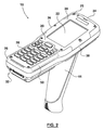
- the portable terminal 10 may be used, e.g. in industrial, retail or supply chain environments to track objects such as barcode labels or RFID tags.
- the portable terminal 10 can take many forms such as, without limitation: a PDA; a cell phone; a smartphone; a pager; a computing tablet, such as an iPad or the like; a digital video camera etc., or any device that has a display coupled to the casing of the device.
- the portable terminal 10 has a number of components including a user interface (e.g. a keyboard 28) located on a front surface 20, one or more onboard processors 50 (e.g. shown by ghosted lines inside of the portable terminal 10), and a communications module 52 (e.g. laser, WLAN, Bluetooth, imager, RFID scanner, etc.), for example located on a back surface 40 of the portable terminal 10, for facilitating wireless communication.
- the portable terminal 10 also has an onboard power source 54 located on the back surface 40 for helping to satisfy power requirements of the onboard processor(s) 50, the user interface, and optionally the communication module 52.
- the portable terminal 10 includes a rigid casing 26, having a proximal end 32, a distal end 34, and a first side 36 and a second side 38 extending between the ends 32, 34.
- Casing 26 can be formed of any suitable material, or combination of materials, including, without limitation: metals, such as aluminium, magnesium or titanium alloys etc; and polymers, glass-filled polymers or other thermoplastic or thermoset materials.
- the power source 54 (e.g. battery) is contained within the casing 26 by a cover 42 that is coupled to the casing 26 on the back surface 40, as either removable or as an integral part of the casing 26.
- the portable terminal 10 may have an optional handle 44, connected via a release securable connection, to a casing 26 of the portable terminal 10.
- the handle 44 may be permanently or otherwise fixedly attached to the casing 26 by fastening means such as but not limited to: protrusions engaged in slots, latch mechanisms, fasteners (e.g. screws), adhesives or other bonding agents, etc.
- the handle 44 may be an integral component of at least a portion of the casing 26 (e.g. molded as part of the casing 26).
- the display assembly 22 is modular in structure including a display (e.g. 106 and 214 in Figures 5 and 7 ) situated between a resilient body (e.g. 108 and 218 in Figures 5 and 7 ) and the housing (e.g. 110 and 220 in Figures 5 and 7 ).
- a sealing gasket e.g. 104 and 204 in Figures 5 and 7
- the cover plate e.g. 24, 102 and 202 in Figures 4 , 5 and 7
- a seal is created such that the ingress of foreign matter (e.g.
- the display may include a touchscreen (e.g. 206 in Figure 7 ) with a touchscreen layer on top of the display to facilitate user interaction, in addition to the keyboard 28.
- the touchscreen layer may be formed from any suitable materials such as Indium Tin Oxide (ITO).
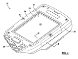
- the cover plate 24 is configured for having an aperture 21 for accommodating interaction (e.g. touch screen functionality) between the user of the portable terminal 10 and the top surface of the display 22.
- the cover plate 24 may include channel 23 to accommodate sealing gasket (e.g. 104 and 204 of Figures 5 and 7 ).
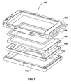
- the display assembly 100 includes a cover plate 102, a sealing gasket 104, a display 106 (this display incorporates an integral touchscreen on top of the display 106), a resilient body 108, and a housing 110.
- the housing 110 includes at least a horizontal (in the illustrated orientation) base portion a vertical (in the illustrated orientation) portion which define an interior compartment 112 where the display 106 and the resilient body 108 are positioned.
- the display assembly 100 may also include a display transition board 114 (shown in Figure 6 ) and a plane grounding spring (not shown).
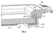
- the resilient body 108 has a horizontal (in the illustrated orientation) base portion and a vertical (in the illustrated orientation) continuous side portion extending upward from the base portion. These portions engage the side and bottom surface of the display 106 to frictionally hold the display 106. Moreover, the resilient body 108 acts as a shock-absorbing layer between display 106 and the housing 110. In another embodiment of the invention, the resilient body 108 may include a ledge portion extending from the top portion of the continuous side portions (i.e. on an end opposite to the base portion) to protect the integrated circuits in the display. This can best be seen in Figure 5 where resilient body 108 includes a ledge portion on the top section of the body 108.
- the sealing gasket 104 can be placed on the display 106.
- the sealing gasket 104 is made of sealing foam and the resilient body 108 is made of silicone rubber, but other suitable materials, and/or combinations of suitable materials, will be apparent to those of skill in the art.
- the material of the sealing gasket 104 may be different from the material of the resilient body 108.
- a material more suitable for sealing e.g. sealing foam
- a more efficient shock-absorbing material to be chosen for the resilient body 108.
- manufacturing of sealing gasket 104 and resilient body 108 is made easier.
- compression molding can be used to create a more precise body such that tighter tolerances can be achieved with respect to the other components of display assembly 100.
- the cover plate 102 is placed over the sealing gasket 104 and fastened to the housing 110, by any suitable means, such as mechanical fasteners or epoxy, etc., creating a seal to prevent foreign material from entering the interior compartment 112 of the housing 110.
- the cover plate 102 includes an expansion gap 101 that accommodates the expansion of sealing gasket 104 laterally into the cover plate 102.
- a channel 103 may be provided in the cover plate 102 to better accommodate the sealing gasket 104.
- the channel 103 is shaped and sized to accommodate the sealing gasket 104 when the cover plate 102 is placed over the sealing gasket 104 and fastened to the housing 110.
- the channel 103 allows for better fitment of the sealing gasket 104, thereby providing a better seal.
- a display assembly 200 includes a cover plate 202, a sealing gasket 204, a touchscreen 206, an adhesive layer 208, a metal spacer 210, a foam spacer 212, a display 214, a resilient body 218 and a housing 220.
- Housing 220 includes at least a horizontal (in the illustrated orientation) base portion a vertical (in the illustrated orientation) portion which define interior compartment 222.
- display 214 does not incorporate a touchscreen directly on the top surface of the display; instead, a touchscreen 206 is provided, which is separated from the display 214 by the metal spacer 210 and foam spacer 212 and the touchscreen 206 is adhered to the metal spacer 210 by the adhesive layer 208.
- the touchscreen 206 includes a touchscreen layer formed from any suitable material such as Indium Tin Oxide (ITO).
- ITO Indium Tin Oxide
- the housing 220 defines an interior compartment 222 where the display 214, the touchscreen 206 and the resilient body 218 are located.
- the display system 200 may also include a display transition board (224 in Figure 8 ) and a plane grounding spring 216.
- the resilient body 218 has a horizontal (in the illustrated orientation) base portion and a vertical (in the illustrated orientation) continuous side portion extending upward from the base portion. These portions engage the sides of the touchscreen 206, metal spacer 210, foam spacer 212 and the display 214 (for the display 214, the base portion of the resilient body 218 also engages the bottom surface of the display 214) to hold them inside the interior compartment 222 (see Figure 7 ) of the housing 220.
- the resilient body 218 provides a shock-absorbing layer to the display 214 and the touchscreen 206 against the housing 220.
- the resilient body 218 may include a ledge portion extending from the top portion of the continuous side portions (i.e. on an end opposite to the base portion) to protect the integrated circuits in the display. This can best be seen in Figure 7 where resilient body 218 includes a ledge portion on the top section of the body 218.
- the sealing gasket 204 can be placed over these components.
- the material of the sealing gasket may be a material that is different from the resilient body 218 and one that can compress and expand more easily.
- the sealing gasket 204 is a sealing foam and the resilient body 218 is a silicone rubber.
- other types of materials can be used as the sealing gasket and as the resilient body.
- the cover plate 202 includes an expansion gap 201 that accommodates the expansion of sealing gasket 204 laterally into the cover plate 202.
- This expansion gap 201 allows the sealing gasket 204 to expand outwardly rather than inwardly into the centre of the touchscreen 206. In effect, the "pillowing" effect discussed above is reduced or eliminated.
- the channel 203 may be provided in the cover plate 202 to better accommodate the sealing gasket 204.
- the channel 203 is shaped and sized to accommodate the sealing gasket 204 when the cover plate 202 is placed over the sealing gasket 204 and fastened to the housing 220.
- the embodiments of the present invention create a seal to prevent foreign material from penetrating the interior compartment 112, 222 of the housing 110, 220.
- This top surface may be a touchscreen 206 as shown in Figures 7 and 8 .
- the top surface may be other types of film layers or coatings.
- the sealing gasket 104, 204 is typically a material that is able to expand and compress much more easily. For example, a sealing foam can be compressed and expanded depending on the types of forces exerted.
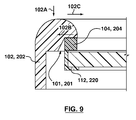
- the sealing gasket 104, 204 is able to expand into (102B as shown in Figure 9 ) the expansion gap 101, 201 in the cover plate 102, 202.
- This expansion gap 101, 201 allows the sealing foam 104, 204 to expand in the direction 102B, rather than just in the direction 102C, reducing, or eliminating, the "pillowing" effect.
- the inward forces exerted on the top surface of the display 106, 214 i.e.
- the sealing gasket 104, 204 is able to move independently from the resilient body 108, 218, the amount of lateral force exerted on the top surface of the display 106, 214 is reduced.
Abstract
Description
- The present invention relates to a display assembly. More specifically, the present invention relates to a display assembly for a portable terminal.
- Wireless communication has advanced significantly over the past few decades. Today, mobile terminals play an important role in consumer and commercial settings. As consumers and business operators utilize portable terminals as an integral part of their lives and businesses, it is increasingly becoming important to be able to take these mobile terminals and access the functionalities provided by these portable terminals where ever they go. As a result, today's portable terminals are frequently used in environments hostile to the portable terminal's electronics. This is particularly true for business operators who may be using these portable terminals in warehouses or in outdoor environments where the devices may be exposed to undesirable foreign matter (e.g. water, other fluids, moisture, particulate matter, dust, etc.), but is also a factor for consumer devices, such as smartphones, digital video cameras and other portable terminals . Accordingly, the sealing feature of a display of the portable terminals and their casings are important for the continued operational integrity of the portable terminals in the presence of such hostile environments.
-
US Patent Publication 2010/0025942 describes a resilient seal component for a mobile terminal to inhibit the penetration of foreign matter from an exterior environment into the interior of a portable terminal. The resilient seal component is positioned between the display and the interior compartment of the portable terminal where the display resides. The resilient seal component has at least one sealing rib to prevent the penetration of foreign matter from the exterior environment into the interior of the portable terminal. - In some cases, as shown in
Figure 1 , it has been found that although an effective seal is created, the display is vulnerable to a phenomenon known as "pillowing". This effect occurs when the top film 302 (e.g. touchscreen layer) is distorted bylateral forces 300B exerted from the top portion of the resilient seal component. As depicted in the Figure, theforce 300A is translated intoforce 300B because thesealing body 304 can only move inwardly. When theinward force 300B is exerted onto thetop film 302 of thedisplay 306, thefilm 302 separates from the display and rises like a "pillow", as shown inFigure 1 . This "pillowing" effect leads to degradation of optical appearance of graphics ondisplay 306, imprecise and inaccurate touch input detection and can also lead to an electrical short between layers, rendering a touch screen inoperative. - Therefore, there is a need for a display assembly that reduces or eliminates this "pillowing" effect and yet which provides an effective seal against unwanted ingress of foreign materials into a portable terminal.
- According to an aspect of the present invention there is provided a display assembly for a portable terminal, the display assembly comprising:
- a housing comprising a base portion and a continuous side portion extending from the base portion to define an interior compartment; a resilient body positioned in the interior compartment of the housing, the resilient body comprising a base portion and a continuous side portion extending from the base portion to define an interior channel;
- a display positioned in the interior channel of the resilient body;
- a cover plate for enclosing the housing, the cover plate having an expansion gap; and a sealing gasket positioned between a surface of the display and the cover plate, the sealing gasket overlapping a portion of the surface of the display;
- wherein when the cover plate is coupled to the housing, the sealing gasket creates a seal between the display and the sealing gasket to inhibit the penetration of foreign matter into the interior compartment of the housing and the expansion gap in the cover plate accommodates expansion of the sealing gasket.
- According to another aspect of the present invention, there is provided a portable terminal, comprising:
- a casing defining at least one interior volume;
- at least one on board processor located within the at least one interior volume; and a display assembly mounted in the at least one portable volume, the display assembly comprising a housing comprising a base portion and a continuous side portion extending from the base portion to define an interior compartment; a resilient body positioned in the interior compartment of the housing, the resilient body comprising a base portion and a continuous side portion extending from the base portion to define an interior channel; a display positioned in the interior channel of the resilient body; a cover plate for enclosing the housing, the cover plate having an expansion gap; and a sealing gasket positioned between a surface of the display and the cover plate, the sealing gasket overlapping a portion of the surface of the display; wherein when the cover plate is coupled to the housing, the sealing gasket creates a seal between the display and the sealing gasket to inhibit the penetration of foreign matter into the interior compartment of the housing and the expansion gap in the cover plate accommodates expansion of the sealing gasket.
- These and other features of the invention will become more apparent from the following description in which reference is made to the appended drawings wherein:
-
Figure 1 shows a prior art display assembly showing the "pillowing" effect; -
Figure 2 shows a perspective top view of a portable terminal according to an embodiment of the present invention; -
Figure 3 shows a perspective bottom view of a portable terminal ofFigure 2 ; -
Figure 4 shows a perspective top view of a display assembly of the portable terminal ofFigure 2 ; -
Figure 5 shows an exploded view of the display assembly according to an embodiment of the invention; -
Figure 6 shows a cross-sectional view of the display assembly ofFigure 5 , taken along line E-E ofFigure 4 ; -
Figure 7 shows an exploded view of the display assembly according to an another embodiment of the present invention; -
Figure 8 shows a cross-section view of the display assembly ofFigure 7 , taken along line E-E ofFigure 4 ; andFigure 9 shows a cross-sectional view of the display assembly ofFigure 5 and7 , taken along line E-E ofFigure 4 . - Referring to now to
Figures 2 and3 , a portable terminal with wireless communication capabilities is indicated generally at 10. Theportable terminal 10 may be used, e.g. in industrial, retail or supply chain environments to track objects such as barcode labels or RFID tags. However, it is recognized that theportable terminal 10 can take many forms such as, without limitation: a PDA; a cell phone; a smartphone; a pager; a computing tablet, such as an iPad or the like; a digital video camera etc., or any device that has a display coupled to the casing of the device. - The
portable terminal 10 has a number of components including a user interface (e.g. a keyboard 28) located on afront surface 20, one or more onboard processors 50 (e.g. shown by ghosted lines inside of the portable terminal 10), and a communications module 52 (e.g. laser, WLAN, Bluetooth, imager, RFID scanner, etc.), for example located on aback surface 40 of theportable terminal 10, for facilitating wireless communication. Theportable terminal 10 also has anonboard power source 54 located on theback surface 40 for helping to satisfy power requirements of the onboard processor(s) 50, the user interface, and optionally thecommunication module 52. Theportable terminal 10 includes arigid casing 26, having aproximal end 32, adistal end 34, and afirst side 36 and asecond side 38 extending between theends -
Casing 26 can be formed of any suitable material, or combination of materials, including, without limitation: metals, such as aluminium, magnesium or titanium alloys etc; and polymers, glass-filled polymers or other thermoplastic or thermoset materials. - The power source 54 (e.g. battery) is contained within the
casing 26 by acover 42 that is coupled to thecasing 26 on theback surface 40, as either removable or as an integral part of thecasing 26. Further, theportable terminal 10 may have anoptional handle 44, connected via a release securable connection, to acasing 26 of theportable terminal 10. Thehandle 44 may be permanently or otherwise fixedly attached to thecasing 26 by fastening means such as but not limited to: protrusions engaged in slots, latch mechanisms, fasteners (e.g. screws), adhesives or other bonding agents, etc. Further, thehandle 44 may be an integral component of at least a portion of the casing 26 (e.g. molded as part of the casing 26). - Referring to
Figure 4 , a perspective view of thedisplay assembly 22 is shown in place incasing 26. Thedisplay assembly 22 is modular in structure including a display (e.g. 106 and 214 inFigures 5 and7 ) situated between a resilient body (e.g. 108 and 218 inFigures 5 and7 ) and the housing (e.g. 110 and 220 inFigures 5 and7 ). A sealing gasket (e.g. 104 and 204 inFigures 5 and7 ) is placed on the top surface of the display and when the cover plate (e.g. 24, 102 and 202 inFigures 4 ,5 and7 ) is placed over the housing, a seal is created such that the ingress of foreign matter (e.g. water, moisture, particulate matter, etc.) around the display and into the interior compartment (e.g. 112 and 222 inFigures 5 and7 ) is inhibited. Further, the display may include a touchscreen (e.g. 206 inFigure 7 ) with a touchscreen layer on top of the display to facilitate user interaction, in addition to thekeyboard 28. The touchscreen layer may be formed from any suitable materials such as Indium Tin Oxide (ITO). - The
cover plate 24 is configured for having anaperture 21 for accommodating interaction (e.g. touch screen functionality) between the user of theportable terminal 10 and the top surface of thedisplay 22. In an embodiment of the present invention, thecover plate 24 may includechannel 23 to accommodate sealing gasket (e.g. 104 and 204 ofFigures 5 and7 ). - Referring now to
Figure 5 , an exploded view ofdisplay assembly 100 is shown. In this embodiment, thedisplay assembly 100 includes acover plate 102, asealing gasket 104, a display 106 (this display incorporates an integral touchscreen on top of the display 106), aresilient body 108, and ahousing 110. Thehousing 110 includes at least a horizontal (in the illustrated orientation) base portion a vertical (in the illustrated orientation) portion which define aninterior compartment 112 where thedisplay 106 and theresilient body 108 are positioned. Thedisplay assembly 100 may also include a display transition board 114 (shown inFigure 6 ) and a plane grounding spring (not shown). - Referring now to
Figure 6 , a cross-section of the assembleddisplay assembly 100 is shown. As can be seen, theresilient body 108 has a horizontal (in the illustrated orientation) base portion and a vertical (in the illustrated orientation) continuous side portion extending upward from the base portion. These portions engage the side and bottom surface of thedisplay 106 to frictionally hold thedisplay 106. Moreover, theresilient body 108 acts as a shock-absorbing layer betweendisplay 106 and thehousing 110. In another embodiment of the invention, theresilient body 108 may include a ledge portion extending from the top portion of the continuous side portions (i.e. on an end opposite to the base portion) to protect the integrated circuits in the display. This can best be seen inFigure 5 whereresilient body 108 includes a ledge portion on the top section of thebody 108. - The
display 106 and theresilient body 108 are then placed in the interior compartment 112 (shown inFigure 5 ) ofhousing 110. Once thedisplay 106 and theresilient body 108 are placed in theinterior compartment 112 ofhousing 110, the sealinggasket 104 can be placed on thedisplay 106. In this particular embodiment, the sealinggasket 104 is made of sealing foam and theresilient body 108 is made of silicone rubber, but other suitable materials, and/or combinations of suitable materials, will be apparent to those of skill in the art. - Advantageously, the material of the sealing
gasket 104 may be different from the material of theresilient body 108. This allows a material more suitable for sealing to be chosen for the sealing gasket 104 (e.g. sealing foam) and a more efficient shock-absorbing material to be chosen for theresilient body 108. Moreover, because they are two separate pieces, manufacturing of sealinggasket 104 andresilient body 108 is made easier. For theresilient body 108, compression molding can be used to create a more precise body such that tighter tolerances can be achieved with respect to the other components ofdisplay assembly 100. - Once the sealing
gasket 104 is in place, thecover plate 102 is placed over the sealinggasket 104 and fastened to thehousing 110, by any suitable means, such as mechanical fasteners or epoxy, etc., creating a seal to prevent foreign material from entering theinterior compartment 112 of thehousing 110. As depicted inFigure 6 , thecover plate 102 includes anexpansion gap 101 that accommodates the expansion of sealinggasket 104 laterally into thecover plate 102. - In another embodiment of the present invention, a
channel 103 may be provided in thecover plate 102 to better accommodate the sealinggasket 104. Thechannel 103 is shaped and sized to accommodate the sealinggasket 104 when thecover plate 102 is placed over the sealinggasket 104 and fastened to thehousing 110. Thechannel 103 allows for better fitment of the sealinggasket 104, thereby providing a better seal. - Referring now to
Figure 7 , an exploded view of another embodiment of the present invention is shown. As shown in this embodiment, adisplay assembly 200 includes acover plate 202, a sealinggasket 204, atouchscreen 206, anadhesive layer 208, ametal spacer 210, afoam spacer 212, adisplay 214, aresilient body 218 and ahousing 220.Housing 220 includes at least a horizontal (in the illustrated orientation) base portion a vertical (in the illustrated orientation) portion which defineinterior compartment 222. Unlike the embodiment shown inFigure 5 ,display 214 does not incorporate a touchscreen directly on the top surface of the display; instead, atouchscreen 206 is provided, which is separated from thedisplay 214 by themetal spacer 210 andfoam spacer 212 and thetouchscreen 206 is adhered to themetal spacer 210 by theadhesive layer 208. Further, thetouchscreen 206 includes a touchscreen layer formed from any suitable material such as Indium Tin Oxide (ITO). Thehousing 220 defines aninterior compartment 222 where thedisplay 214, thetouchscreen 206 and theresilient body 218 are located. Thedisplay system 200 may also include a display transition board (224 inFigure 8 ) and aplane grounding spring 216. - Now referring to
Figure 8 , a cross-section of thedisplay assembly 200 along line E-E (seeFigure 4 ) of the embodiment shown inFigure 7 is shown. As it can be seen, theresilient body 218 has a horizontal (in the illustrated orientation) base portion and a vertical (in the illustrated orientation) continuous side portion extending upward from the base portion. These portions engage the sides of thetouchscreen 206,metal spacer 210,foam spacer 212 and the display 214 (for thedisplay 214, the base portion of theresilient body 218 also engages the bottom surface of the display 214) to hold them inside the interior compartment 222 (seeFigure 7 ) of thehousing 220. Theresilient body 218 provides a shock-absorbing layer to thedisplay 214 and thetouchscreen 206 against thehousing 220. In another embodiment of the invention, theresilient body 218 may include a ledge portion extending from the top portion of the continuous side portions (i.e. on an end opposite to the base portion) to protect the integrated circuits in the display. This can best be seen inFigure 7 whereresilient body 218 includes a ledge portion on the top section of thebody 218. - Once the components and the
resilient body 218 are placed in theinterior compartment 222 of thehousing 220, the sealinggasket 204 can be placed over these components. The material of the sealing gasket may be a material that is different from theresilient body 218 and one that can compress and expand more easily. In this particular embodiment, the sealinggasket 204 is a sealing foam and theresilient body 218 is a silicone rubber. However, other types of materials can be used as the sealing gasket and as the resilient body. Thereafter, thecover plate 202 is placed over the sealinggasket 204 and fastened to thehousing 220, by any suitable means, creating a seal to prevent foreign material from entering theinterior compartment 222 of thehousing 220. As depicted inFigure 8 , thecover plate 202 includes anexpansion gap 201 that accommodates the expansion of sealinggasket 204 laterally into thecover plate 202. Thisexpansion gap 201 allows the sealinggasket 204 to expand outwardly rather than inwardly into the centre of thetouchscreen 206. In effect, the "pillowing" effect discussed above is reduced or eliminated. - The
channel 203 may be provided in thecover plate 202 to better accommodate the sealinggasket 204. Thechannel 203 is shaped and sized to accommodate the sealinggasket 204 when thecover plate 202 is placed over the sealinggasket 204 and fastened to thehousing 220. - Once assembled, the embodiments of the present invention create a seal to prevent foreign material from penetrating the
interior compartment housing gasket display touchscreen 206 as shown inFigures 7 and8 . In other embodiments, the top surface may be other types of film layers or coatings. Unlike theresilient body gasket Figure 9 , as pressure is exerted downwardly from thecover plate 102, 202 (i.e.force 102A), the sealinggasket Figure 9 ) theexpansion gap cover plate expansion gap foam direction 102B, rather than just in thedirection 102C, reducing, or eliminating, the "pillowing" effect. As described above, the inward forces exerted on the top surface of thedisplay 106, 214 (i.e. 206 inFigures 7 and8 ) forces the top surface of the display (which may be a film, coating or a touchscreen as in 206 ofFigures 7 and8 having a touchscreen layer) to separate from the display and rise, creating a "pillowing" of the display. By providing anexpansion gap gasket cover plate display display - Advantageously, since the sealing
gasket resilient body display - One or more currently preferred embodiments have been described by way of example. It will be apparent to persons skilled in the art that a number of variations and modifications can be made without departing from the scope of the invention as defined in the claims.
Claims (14)
- A display assembly (100, 200) for a portable terminal (10), the display assembly comprising:a housing (110, 220) comprising a base portion and a continuous side portion extending from the base portion to define an interior compartment (112, 222);a resilient body (108, 218) positioned in the interior compartment of the housing, the resilient body comprising a base portion and a continuous side portion extending from the base portion to define an interior channel;a display (106, 214) positioned in the interior channel of the resilient body;a cover plate (102, 202) for enclosing the housing, the cover plate having an expansion gap (101, 201); anda sealing gasket (104,204) positioned between a surface of the display and the cover plate, the sealing gasket overlapping a portion of the surface of the display; wherein, when the cover plate is coupled to the housing, the sealing gasket creates a seal between the display and the sealing gasket to inhibit the penetration of foreign matter into the interior compartment of the housing and the expansion gap in the cover plate accommodates expansion of the sealing gasket.
- A display assembly according to claim 1, wherein the sealing gasket is formed from a sealing foam.
- A display assembly according to any preceding claim, the cover plate further comprising a channel (103, 203) to accommodate the sealing gasket, the channel having dimensions sufficient to encapsulate the sealing gasket.
- A display assembly according to any preceding claim, further comprising a touchscreen layer (206) positioned between the display and the sealing gasket.
- A display assembly according to claim 4, wherein the touchscreen is adhered to the surface of the display by an adhesive layer (208).
- A display assembly according to claim 4, wherein the touchscreen and the display are separated by a metal spacer (210) and a foam spacer (212), the touchscreen adhered to the metal spacer by an adhesive layer (208).
- A display assembly according to any of claims 4 through 6, wherein the touchscreen layer is an indium tin oxide (ITO) layer.
- A display assembly according to any preceding claim, the resilient body further comprising a ledge portion extending parallel to the base portion, inwardly from the continuous side portion, the ledge portion for protecting an integrated circuit portion of the display.
- A display assembly according to any preceding claim, further comprising a display transition board (114, 224) coupled to the display.
- A display assembly according to any preceding claim, further comprising a plane grounding spring (216) coupled to the display.
- A display assembly according to any preceding claim, wherein the resilient body (108, 218) is formed from silicone rubber.
- A display assembly according to any preceding claim, wherein the resilient body is compression moulded.
- A display assembly according to any preceding claim wherein the display assembly is a module that can be incorporated into the casing of a portable terminal.
- A portable terminal (10), comprising:a casing (26) defining at least one interior volume;at least one on board processor (50) located within the at least one interior volume; anda display assembly (100, 200 mounted in the at least one portable volume, the display assembly comprising:a housing (110, 220) comprising a base portion and a continuous side portion extending from the base portion to define an interior compartment (112, 222);a resilient body (108, 218) positioned in the interior compartment of the housing, the resilient body comprising a base portion and a continuous side portion extending from the base portion to define an interior channel;a display (106, 214) positioned in the interior channel of the resilient body;a cover plate (102, 202) for enclosing the housing, the cover plate having an expansion gap (101, 201); anda sealing gasket (104,204) positioned between a surface of the display and the cover plate, the sealing gasket overlapping a portion of the surface of the display;wherein, when the cover plate is coupled to the housing, the sealing gasket creates a seal between the display and the sealing gasket to inhibit the penetration of foreign matter into the interior compartment of the housing and the expansion gap in the cover plate accommodates expansion of the sealing gasket.
Applications Claiming Priority (1)
| Application Number | Priority Date | Filing Date | Title |
|---|---|---|---|
| US12/766,152 US8520373B2 (en) | 2010-04-23 | 2010-04-23 | Display assembly for a portable module |
Publications (3)
| Publication Number | Publication Date |
|---|---|
| EP2381332A2 true EP2381332A2 (en) | 2011-10-26 |
| EP2381332A3 EP2381332A3 (en) | 2014-05-14 |
| EP2381332B1 EP2381332B1 (en) | 2017-07-12 |
Family
ID=43661947
Family Applications (1)
| Application Number | Title | Priority Date | Filing Date |
|---|---|---|---|
| EP10192934.7A Active EP2381332B1 (en) | 2010-04-23 | 2010-11-29 | A display assembly for a portable terminal |
Country Status (2)
| Country | Link |
|---|---|
| US (1) | US8520373B2 (en) |
| EP (1) | EP2381332B1 (en) |
Cited By (5)
| Publication number | Priority date | Publication date | Assignee | Title |
|---|---|---|---|---|
| US9264089B2 (en) | 2013-03-15 | 2016-02-16 | A.G. Findings & Mfg. Co. | Waterproof mobile device case |
| WO2016082749A1 (en) * | 2014-11-25 | 2016-06-02 | 华为技术有限公司 | Housing assembly and terminal |
| CN107949193A (en) * | 2017-11-08 | 2018-04-20 | 苏州蓝博控制技术有限公司 | Installation shell with shock-damping structure and liquid crystal display instrument is bonded entirely |
| WO2021134670A1 (en) * | 2019-12-31 | 2021-07-08 | 深圳康荣电子有限公司 | Apparatus support, module support and television |
| EP3848774A3 (en) * | 2019-12-20 | 2021-11-03 | Samsung Electronics Co., Ltd. | Wearable electronic device including ventilation and waterproof structure |
Families Citing this family (32)
| Publication number | Priority date | Publication date | Assignee | Title |
|---|---|---|---|---|
| US8965458B2 (en) | 2009-08-21 | 2015-02-24 | Otter Products, Llc | Protective cushion cover for an electronic device |
| US20130003329A1 (en) * | 2009-09-01 | 2013-01-03 | Airo Wireless, Inc. | Ruggedized handset housing |
| US9081428B2 (en) * | 2010-04-23 | 2015-07-14 | Psion Inc. | Apparatus and method for impact resistant touchscreen display module |
| US8492661B2 (en) * | 2010-08-27 | 2013-07-23 | Apple Inc. | Inhibiting moisture intrusion in a very small form factor consumer electronic product |
| US8415570B2 (en) * | 2010-08-27 | 2013-04-09 | Apple Inc. | Inhibiting moisture intrusion in a very small form factor consumer electronic product |
| MX2013004136A (en) * | 2010-10-12 | 2013-08-21 | Treefrog Developments Inc | Housing for encasing an electronic device. |
| US9549598B2 (en) | 2010-10-12 | 2017-01-24 | Treefrog Developments, Inc. | Housing for encasing an electronic device |
| EP2718781B2 (en) | 2011-06-13 | 2019-10-23 | TreeFrog Developments, Inc. | Housing for encasing a tablet computer |
| US9615476B2 (en) | 2011-06-13 | 2017-04-04 | Treefrog Developments, Inc. | Housing for encasing a mobile device |
| JP5542100B2 (en) * | 2011-06-29 | 2014-07-09 | 株式会社ソニー・コンピュータエンタテインメント | Portable electronic devices |
| JP5627032B2 (en) * | 2012-04-27 | 2014-11-19 | レノボ・シンガポール・プライベート・リミテッド | Housing material, method for manufacturing the casing material, casing for electronic device using the casing material, manufacturing method for casing for electronic device, and electronic device using the casing for electronic device |
| US9469469B2 (en) | 2012-06-01 | 2016-10-18 | Treefrog Developments, Inc. | Housing for encasing an object having a thin profile |
| US9241551B2 (en) | 2012-06-13 | 2016-01-26 | Otter Products, Llc | Protective case with compartment |
| US9733670B2 (en) * | 2012-09-26 | 2017-08-15 | Apple Inc. | Computer display or cover glass/cell attachment to frame |
| US9282668B2 (en) | 2012-09-28 | 2016-03-08 | Htc Corporation | Electronic apparatus and method for assembling the same |
| US9137918B2 (en) * | 2012-09-28 | 2015-09-15 | Htc Corporation | Electronic apparatus and method for assembling the same |
| US9332329B2 (en) | 2012-09-28 | 2016-05-03 | Htc Corporation | Electronic apparatus |
| US9785186B2 (en) * | 2012-10-16 | 2017-10-10 | Samsung Electronics Co., Ltd. | Package system with cover structure and method of operation thereof |
| KR20140095851A (en) * | 2013-01-25 | 2014-08-04 | 삼성디스플레이 주식회사 | Organic light emitting diode display |
| WO2014145062A1 (en) | 2013-03-15 | 2014-09-18 | Honeywell International Inc. | Electrostatic discharge connector and method for an electronic device |
| US20140324227A1 (en) | 2013-04-30 | 2014-10-30 | Honeywell International Inc. | Hvac controller having a fixed segment display with an interactive message center |
| JP6051103B2 (en) * | 2013-05-23 | 2016-12-27 | 富士通株式会社 | Waterproof structure and electronic equipment |
| CN104680936A (en) * | 2013-11-29 | 2015-06-03 | 富泰华工业(深圳)有限公司 | Display |
| US9374922B1 (en) * | 2014-12-31 | 2016-06-21 | Avalue Technology Inc. | Waterproof structure for use in display device |
| KR102376981B1 (en) * | 2015-04-22 | 2022-03-21 | 삼성전자주식회사 | Electronic device having heat transffering structure |
| US9577697B2 (en) | 2015-05-27 | 2017-02-21 | Otter Products, Llc | Protective case with stylus access feature |
| US10159320B2 (en) | 2016-09-07 | 2018-12-25 | Otter Products, Llc | Protective enclosure for encasing an electronic device |
| CN109669561A (en) * | 2017-10-13 | 2019-04-23 | 苏州欧菲光科技有限公司 | Touch control component and vehicle |
| US10827809B2 (en) | 2018-04-05 | 2020-11-10 | Otter Products, Llc | Protective case for electronic device |
| KR102091113B1 (en) * | 2018-07-27 | 2020-03-19 | 코츠테크놀로지주식회사 | Slim type large area display device |
| TWI709024B (en) * | 2019-12-05 | 2020-11-01 | 優鋼機械股份有限公司 | Display protecting device |
| US11640185B2 (en) * | 2020-09-14 | 2023-05-02 | Zebra Technologies Corporation | Mobile device and assembly process |
Citations (1)
| Publication number | Priority date | Publication date | Assignee | Title |
|---|---|---|---|---|
| US20100025942A1 (en) | 2008-07-29 | 2010-02-04 | Psion Teklogix Inc. | Sealing system and seal component for a display assembly of a portable device |
Family Cites Families (9)
| Publication number | Priority date | Publication date | Assignee | Title |
|---|---|---|---|---|
| US5479285A (en) * | 1993-09-01 | 1995-12-26 | Ncr Corporation | Liquid crystal device with an isotropic shock mounting and gasket |
| US6532152B1 (en) * | 1998-11-16 | 2003-03-11 | Intermec Ip Corp. | Ruggedized hand held computer |
| US6897852B2 (en) * | 2002-03-28 | 2005-05-24 | Symbol Technologies, Inc. | Information input display device |
| US20060209012A1 (en) * | 2005-02-23 | 2006-09-21 | Pixtronix, Incorporated | Devices having MEMS displays |
| US20060227114A1 (en) * | 2005-03-30 | 2006-10-12 | Geaghan Bernard O | Touch location determination with error correction for sensor movement |
| US8023261B2 (en) * | 2008-09-05 | 2011-09-20 | Apple Inc. | Electronic device assembly |
| JP4812137B2 (en) * | 2008-09-24 | 2011-11-09 | Necアクセステクニカ株式会社 | Panel mounting structure, sandwiching member and panel mounting method |
| US20110260829A1 (en) * | 2010-04-21 | 2011-10-27 | Research In Motion Limited | Method of providing security on a portable electronic device having a touch-sensitive display |
| US7876288B1 (en) * | 2010-08-11 | 2011-01-25 | Chumby Industries, Inc. | Touchscreen with a light modulator |
-
2010
- 2010-04-23 US US12/766,152 patent/US8520373B2/en active Active
- 2010-11-29 EP EP10192934.7A patent/EP2381332B1/en active Active
Patent Citations (1)
| Publication number | Priority date | Publication date | Assignee | Title |
|---|---|---|---|---|
| US20100025942A1 (en) | 2008-07-29 | 2010-02-04 | Psion Teklogix Inc. | Sealing system and seal component for a display assembly of a portable device |
Cited By (7)
| Publication number | Priority date | Publication date | Assignee | Title |
|---|---|---|---|---|
| US9264089B2 (en) | 2013-03-15 | 2016-02-16 | A.G. Findings & Mfg. Co. | Waterproof mobile device case |
| WO2016082749A1 (en) * | 2014-11-25 | 2016-06-02 | 华为技术有限公司 | Housing assembly and terminal |
| CN107949193A (en) * | 2017-11-08 | 2018-04-20 | 苏州蓝博控制技术有限公司 | Installation shell with shock-damping structure and liquid crystal display instrument is bonded entirely |
| CN107949193B (en) * | 2017-11-08 | 2023-12-01 | 苏州蓝博控制技术有限公司 | Mounting shell with shock-absorbing structure and full-lamination liquid crystal display instrument |
| EP3848774A3 (en) * | 2019-12-20 | 2021-11-03 | Samsung Electronics Co., Ltd. | Wearable electronic device including ventilation and waterproof structure |
| US11553608B2 (en) | 2019-12-20 | 2023-01-10 | Samsung Electronics Co., Ltd. | Wearable electronic device including ventilation and waterproof structure |
| WO2021134670A1 (en) * | 2019-12-31 | 2021-07-08 | 深圳康荣电子有限公司 | Apparatus support, module support and television |
Also Published As
| Publication number | Publication date |
|---|---|
| US8520373B2 (en) | 2013-08-27 |
| EP2381332B1 (en) | 2017-07-12 |
| US20110261510A1 (en) | 2011-10-27 |
| EP2381332A3 (en) | 2014-05-14 |
Similar Documents
| Publication | Publication Date | Title |
|---|---|---|
| EP2381332B1 (en) | A display assembly for a portable terminal | |
| KR102246134B1 (en) | Electronic device and protection cover thereof | |
| US8800764B2 (en) | Watertight casing for portable electronic device | |
| US8032194B2 (en) | Housing of portable electronic devices | |
| US8482697B2 (en) | Protecting module and portable electronic device using the same | |
| US20160299532A1 (en) | An apparatus and method of providing an apparatus comprising a bendable portion | |
| EP2773083B1 (en) | Fixation of the battery with a metal plate to the housing of an electronic device | |
| US20120071217A1 (en) | Protector for smartphone | |
| US9338910B2 (en) | Electronic device and sealed structure | |
| US20130170159A1 (en) | Housing for portable electronic devices | |
| US9137918B2 (en) | Electronic apparatus and method for assembling the same | |
| KR102220753B1 (en) | DISPLAY SCREEN ASSEMBLY, ASSEMBLING METHOD THEREOF AND ELECTRONIC DEVICE | |
| KR200465497Y1 (en) | Case for mobile communication terminal | |
| US8939284B2 (en) | Cushion of folding portable electronic device and waterproof structure of folding portable electronic device | |
| CN108337336B (en) | Electronic component and electronic device | |
| JP2001175608A (en) | Portable information terminal device | |
| CN108881552B (en) | Electronic equipment | |
| EP2629493B1 (en) | Housing for electronic device | |
| US9339101B2 (en) | Fixation module | |
| JP6088249B2 (en) | Mobile device | |
| JP2013247655A (en) | Electronic apparatus | |
| US8254099B2 (en) | Housing of portable electronic device | |
| JP5905796B2 (en) | Mobile device | |
| US7851710B2 (en) | Waterproof and dustproof structure | |
| EP2709342B1 (en) | Shielding layer used to fix housings parts together |
Legal Events
| Date | Code | Title | Description |
|---|---|---|---|
| AK | Designated contracting states |
Kind code of ref document: A2 Designated state(s): AL AT BE BG CH CY CZ DE DK EE ES FI FR GB GR HR HU IE IS IT LI LT LU LV MC MK MT NL NO PL PT RO RS SE SI SK SM TR |
|
| AX | Request for extension of the european patent |
Extension state: BA ME |
|
| PUAI | Public reference made under article 153(3) epc to a published international application that has entered the european phase |
Free format text: ORIGINAL CODE: 0009012 |
|
| PUAL | Search report despatched |
Free format text: ORIGINAL CODE: 0009013 |
|
| AK | Designated contracting states |
Kind code of ref document: A3 Designated state(s): AL AT BE BG CH CY CZ DE DK EE ES FI FR GB GR HR HU IE IS IT LI LT LU LV MC MK MT NL NO PL PT RO RS SE SI SK SM TR |
|
| AX | Request for extension of the european patent |
Extension state: BA ME |
|
| RIC1 | Information provided on ipc code assigned before grant |
Ipc: G06F 1/16 20060101AFI20140410BHEP |
|
| 17P | Request for examination filed |
Effective date: 20141114 |
|
| RBV | Designated contracting states (corrected) |
Designated state(s): AL AT BE BG CH CY CZ DE DK EE ES FI FR GB GR HR HU IE IS IT LI LT LU LV MC MK MT NL NO PL PT RO RS SE SI SK SM TR |
|
| 17Q | First examination report despatched |
Effective date: 20151117 |
|
| GRAP | Despatch of communication of intention to grant a patent |
Free format text: ORIGINAL CODE: EPIDOSNIGR1 |
|
| STAA | Information on the status of an ep patent application or granted ep patent |
Free format text: STATUS: GRANT OF PATENT IS INTENDED |
|
| INTG | Intention to grant announced |
Effective date: 20170224 |
|
| GRAS | Grant fee paid |
Free format text: ORIGINAL CODE: EPIDOSNIGR3 |
|
| GRAA | (expected) grant |
Free format text: ORIGINAL CODE: 0009210 |
|
| STAA | Information on the status of an ep patent application or granted ep patent |
Free format text: STATUS: THE PATENT HAS BEEN GRANTED |
|
| GRAT | Correction requested after decision to grant or after decision to maintain patent in amended form |
Free format text: ORIGINAL CODE: EPIDOSNCDEC |
|
| AK | Designated contracting states |
Kind code of ref document: B1 Designated state(s): AL AT BE BG CH CY CZ DE DK EE ES FI FR GB GR HR HU IE IS IT LI LT LU LV MC MK MT NL NO PL PT RO RS SE SI SK SM TR |
|
| REG | Reference to a national code |
Ref country code: GB Ref legal event code: FG4D |
|
| REG | Reference to a national code |
Ref country code: CH Ref legal event code: EP |
|
| REG | Reference to a national code |
Ref country code: AT Ref legal event code: REF Ref document number: 908927 Country of ref document: AT Kind code of ref document: T Effective date: 20170715 |
|
| REG | Reference to a national code |
Ref country code: IE Ref legal event code: FG4D |
|
| REG | Reference to a national code |
Ref country code: DE Ref legal event code: R096 Ref document number: 602010043533 Country of ref document: DE |
|
| REG | Reference to a national code |
Ref country code: NL Ref legal event code: MP Effective date: 20170712 |
|
| REG | Reference to a national code |
Ref country code: LT Ref legal event code: MG4D |
|
| REG | Reference to a national code |
Ref country code: AT Ref legal event code: MK05 Ref document number: 908927 Country of ref document: AT Kind code of ref document: T Effective date: 20170712 |
|
| PG25 | Lapsed in a contracting state [announced via postgrant information from national office to epo] |
Ref country code: NO Free format text: LAPSE BECAUSE OF FAILURE TO SUBMIT A TRANSLATION OF THE DESCRIPTION OR TO PAY THE FEE WITHIN THE PRESCRIBED TIME-LIMIT Effective date: 20171012 Ref country code: FI Free format text: LAPSE BECAUSE OF FAILURE TO SUBMIT A TRANSLATION OF THE DESCRIPTION OR TO PAY THE FEE WITHIN THE PRESCRIBED TIME-LIMIT Effective date: 20170712 Ref country code: LT Free format text: LAPSE BECAUSE OF FAILURE TO SUBMIT A TRANSLATION OF THE DESCRIPTION OR TO PAY THE FEE WITHIN THE PRESCRIBED TIME-LIMIT Effective date: 20170712 Ref country code: AT Free format text: LAPSE BECAUSE OF FAILURE TO SUBMIT A TRANSLATION OF THE DESCRIPTION OR TO PAY THE FEE WITHIN THE PRESCRIBED TIME-LIMIT Effective date: 20170712 Ref country code: HR Free format text: LAPSE BECAUSE OF FAILURE TO SUBMIT A TRANSLATION OF THE DESCRIPTION OR TO PAY THE FEE WITHIN THE PRESCRIBED TIME-LIMIT Effective date: 20170712 Ref country code: NL Free format text: LAPSE BECAUSE OF FAILURE TO SUBMIT A TRANSLATION OF THE DESCRIPTION OR TO PAY THE FEE WITHIN THE PRESCRIBED TIME-LIMIT Effective date: 20170712 Ref country code: SE Free format text: LAPSE BECAUSE OF FAILURE TO SUBMIT A TRANSLATION OF THE DESCRIPTION OR TO PAY THE FEE WITHIN THE PRESCRIBED TIME-LIMIT Effective date: 20170712 |
|
| PG25 | Lapsed in a contracting state [announced via postgrant information from national office to epo] |
Ref country code: BG Free format text: LAPSE BECAUSE OF FAILURE TO SUBMIT A TRANSLATION OF THE DESCRIPTION OR TO PAY THE FEE WITHIN THE PRESCRIBED TIME-LIMIT Effective date: 20171012 Ref country code: PL Free format text: LAPSE BECAUSE OF FAILURE TO SUBMIT A TRANSLATION OF THE DESCRIPTION OR TO PAY THE FEE WITHIN THE PRESCRIBED TIME-LIMIT Effective date: 20170712 Ref country code: IS Free format text: LAPSE BECAUSE OF FAILURE TO SUBMIT A TRANSLATION OF THE DESCRIPTION OR TO PAY THE FEE WITHIN THE PRESCRIBED TIME-LIMIT Effective date: 20171112 Ref country code: GR Free format text: LAPSE BECAUSE OF FAILURE TO SUBMIT A TRANSLATION OF THE DESCRIPTION OR TO PAY THE FEE WITHIN THE PRESCRIBED TIME-LIMIT Effective date: 20171013 Ref country code: RS Free format text: LAPSE BECAUSE OF FAILURE TO SUBMIT A TRANSLATION OF THE DESCRIPTION OR TO PAY THE FEE WITHIN THE PRESCRIBED TIME-LIMIT Effective date: 20170712 Ref country code: ES Free format text: LAPSE BECAUSE OF FAILURE TO SUBMIT A TRANSLATION OF THE DESCRIPTION OR TO PAY THE FEE WITHIN THE PRESCRIBED TIME-LIMIT Effective date: 20170712 Ref country code: LV Free format text: LAPSE BECAUSE OF FAILURE TO SUBMIT A TRANSLATION OF THE DESCRIPTION OR TO PAY THE FEE WITHIN THE PRESCRIBED TIME-LIMIT Effective date: 20170712 |
|
| REG | Reference to a national code |
Ref country code: DE Ref legal event code: R097 Ref document number: 602010043533 Country of ref document: DE |
|
| PG25 | Lapsed in a contracting state [announced via postgrant information from national office to epo] |
Ref country code: DK Free format text: LAPSE BECAUSE OF FAILURE TO SUBMIT A TRANSLATION OF THE DESCRIPTION OR TO PAY THE FEE WITHIN THE PRESCRIBED TIME-LIMIT Effective date: 20170712 Ref country code: CZ Free format text: LAPSE BECAUSE OF FAILURE TO SUBMIT A TRANSLATION OF THE DESCRIPTION OR TO PAY THE FEE WITHIN THE PRESCRIBED TIME-LIMIT Effective date: 20170712 Ref country code: RO Free format text: LAPSE BECAUSE OF FAILURE TO SUBMIT A TRANSLATION OF THE DESCRIPTION OR TO PAY THE FEE WITHIN THE PRESCRIBED TIME-LIMIT Effective date: 20170712 |
|
| PLBE | No opposition filed within time limit |
Free format text: ORIGINAL CODE: 0009261 |
|
| STAA | Information on the status of an ep patent application or granted ep patent |
Free format text: STATUS: NO OPPOSITION FILED WITHIN TIME LIMIT |
|
| PG25 | Lapsed in a contracting state [announced via postgrant information from national office to epo] |
Ref country code: IT Free format text: LAPSE BECAUSE OF FAILURE TO SUBMIT A TRANSLATION OF THE DESCRIPTION OR TO PAY THE FEE WITHIN THE PRESCRIBED TIME-LIMIT Effective date: 20170712 Ref country code: SM Free format text: LAPSE BECAUSE OF FAILURE TO SUBMIT A TRANSLATION OF THE DESCRIPTION OR TO PAY THE FEE WITHIN THE PRESCRIBED TIME-LIMIT Effective date: 20170712 Ref country code: SK Free format text: LAPSE BECAUSE OF FAILURE TO SUBMIT A TRANSLATION OF THE DESCRIPTION OR TO PAY THE FEE WITHIN THE PRESCRIBED TIME-LIMIT Effective date: 20170712 Ref country code: EE Free format text: LAPSE BECAUSE OF FAILURE TO SUBMIT A TRANSLATION OF THE DESCRIPTION OR TO PAY THE FEE WITHIN THE PRESCRIBED TIME-LIMIT Effective date: 20170712 |
|
| 26N | No opposition filed |
Effective date: 20180413 |
|
| PG25 | Lapsed in a contracting state [announced via postgrant information from national office to epo] |
Ref country code: MC Free format text: LAPSE BECAUSE OF FAILURE TO SUBMIT A TRANSLATION OF THE DESCRIPTION OR TO PAY THE FEE WITHIN THE PRESCRIBED TIME-LIMIT Effective date: 20170712 |
|
| PG25 | Lapsed in a contracting state [announced via postgrant information from national office to epo] |
Ref country code: LI Free format text: LAPSE BECAUSE OF NON-PAYMENT OF DUE FEES Effective date: 20171130 Ref country code: CH Free format text: LAPSE BECAUSE OF NON-PAYMENT OF DUE FEES Effective date: 20171130 |
|
| PG25 | Lapsed in a contracting state [announced via postgrant information from national office to epo] |
Ref country code: LU Free format text: LAPSE BECAUSE OF NON-PAYMENT OF DUE FEES Effective date: 20171129 Ref country code: SI Free format text: LAPSE BECAUSE OF FAILURE TO SUBMIT A TRANSLATION OF THE DESCRIPTION OR TO PAY THE FEE WITHIN THE PRESCRIBED TIME-LIMIT Effective date: 20170712 |
|
| REG | Reference to a national code |
Ref country code: FR Ref legal event code: ST Effective date: 20180731 Ref country code: BE Ref legal event code: MM Effective date: 20171130 |
|
| REG | Reference to a national code |
Ref country code: IE Ref legal event code: MM4A |
|
| PG25 | Lapsed in a contracting state [announced via postgrant information from national office to epo] |
Ref country code: MT Free format text: LAPSE BECAUSE OF NON-PAYMENT OF DUE FEES Effective date: 20171129 |
|
| PG25 | Lapsed in a contracting state [announced via postgrant information from national office to epo] |
Ref country code: FR Free format text: LAPSE BECAUSE OF NON-PAYMENT OF DUE FEES Effective date: 20171130 Ref country code: IE Free format text: LAPSE BECAUSE OF NON-PAYMENT OF DUE FEES Effective date: 20171129 |
|
| PG25 | Lapsed in a contracting state [announced via postgrant information from national office to epo] |
Ref country code: BE Free format text: LAPSE BECAUSE OF NON-PAYMENT OF DUE FEES Effective date: 20171130 |
|
| PG25 | Lapsed in a contracting state [announced via postgrant information from national office to epo] |
Ref country code: HU Free format text: LAPSE BECAUSE OF FAILURE TO SUBMIT A TRANSLATION OF THE DESCRIPTION OR TO PAY THE FEE WITHIN THE PRESCRIBED TIME-LIMIT; INVALID AB INITIO Effective date: 20101129 |
|
| PG25 | Lapsed in a contracting state [announced via postgrant information from national office to epo] |
Ref country code: CY Free format text: LAPSE BECAUSE OF NON-PAYMENT OF DUE FEES Effective date: 20170712 |
|
| PG25 | Lapsed in a contracting state [announced via postgrant information from national office to epo] |
Ref country code: MK Free format text: LAPSE BECAUSE OF FAILURE TO SUBMIT A TRANSLATION OF THE DESCRIPTION OR TO PAY THE FEE WITHIN THE PRESCRIBED TIME-LIMIT Effective date: 20170712 |
|
| PG25 | Lapsed in a contracting state [announced via postgrant information from national office to epo] |
Ref country code: TR Free format text: LAPSE BECAUSE OF FAILURE TO SUBMIT A TRANSLATION OF THE DESCRIPTION OR TO PAY THE FEE WITHIN THE PRESCRIBED TIME-LIMIT Effective date: 20170712 |
|
| PG25 | Lapsed in a contracting state [announced via postgrant information from national office to epo] |
Ref country code: PT Free format text: LAPSE BECAUSE OF FAILURE TO SUBMIT A TRANSLATION OF THE DESCRIPTION OR TO PAY THE FEE WITHIN THE PRESCRIBED TIME-LIMIT Effective date: 20170712 |
|
| PG25 | Lapsed in a contracting state [announced via postgrant information from national office to epo] |
Ref country code: AL Free format text: LAPSE BECAUSE OF FAILURE TO SUBMIT A TRANSLATION OF THE DESCRIPTION OR TO PAY THE FEE WITHIN THE PRESCRIBED TIME-LIMIT Effective date: 20170712 |
|
| P01 | Opt-out of the competence of the unified patent court (upc) registered |
Effective date: 20230411 |
|
| PGFP | Annual fee paid to national office [announced via postgrant information from national office to epo] |
Ref country code: GB Payment date: 20231019 Year of fee payment: 14 |
|
| PGFP | Annual fee paid to national office [announced via postgrant information from national office to epo] |
Ref country code: DE Payment date: 20231019 Year of fee payment: 14 |