EP2380529A1 - Knee orthotic and method for operating same - Google Patents
Knee orthotic and method for operating same Download PDFInfo
- Publication number
- EP2380529A1 EP2380529A1 EP11004660A EP11004660A EP2380529A1 EP 2380529 A1 EP2380529 A1 EP 2380529A1 EP 11004660 A EP11004660 A EP 11004660A EP 11004660 A EP11004660 A EP 11004660A EP 2380529 A1 EP2380529 A1 EP 2380529A1
- Authority
- EP
- European Patent Office
- Prior art keywords
- knee
- thigh
- lower leg
- actuator unit
- rail
- Prior art date
- Legal status (The legal status is an assumption and is not a legal conclusion. Google has not performed a legal analysis and makes no representation as to the accuracy of the status listed.)
- Granted
Links
- 210000003127 knee Anatomy 0.000 title claims abstract description 62
- 238000000034 method Methods 0.000 title claims abstract description 8
- 210000000689 upper leg Anatomy 0.000 claims abstract description 71
- 210000001699 lower leg Anatomy 0.000 claims abstract description 69
- 238000013016 damping Methods 0.000 claims abstract description 17
- 230000033001 locomotion Effects 0.000 claims abstract description 14
- 210000002683 foot Anatomy 0.000 claims description 22
- 210000003423 ankle Anatomy 0.000 claims description 10
- 230000007246 mechanism Effects 0.000 abstract description 9
- 230000001419 dependent effect Effects 0.000 abstract description 2
- 210000002414 leg Anatomy 0.000 description 15
- 230000000750 progressive effect Effects 0.000 description 6
- 230000009471 action Effects 0.000 description 5
- 239000000835 fiber Substances 0.000 description 5
- 210000000629 knee joint Anatomy 0.000 description 5
- 238000005452 bending Methods 0.000 description 4
- 230000008859 change Effects 0.000 description 4
- 238000013461 design Methods 0.000 description 4
- 238000011161 development Methods 0.000 description 4
- 230000018109 developmental process Effects 0.000 description 4
- 230000007935 neutral effect Effects 0.000 description 4
- 206010033799 Paralysis Diseases 0.000 description 3
- 239000002131 composite material Substances 0.000 description 3
- 239000012530 fluid Substances 0.000 description 3
- 208000027418 Wounds and injury Diseases 0.000 description 2
- 230000003321 amplification Effects 0.000 description 2
- 230000008901 benefit Effects 0.000 description 2
- 230000006378 damage Effects 0.000 description 2
- 230000007423 decrease Effects 0.000 description 2
- 208000014674 injury Diseases 0.000 description 2
- 210000003205 muscle Anatomy 0.000 description 2
- 238000003199 nucleic acid amplification method Methods 0.000 description 2
- 238000005096 rolling process Methods 0.000 description 2
- 230000000638 stimulation Effects 0.000 description 2
- OKTJSMMVPCPJKN-UHFFFAOYSA-N Carbon Chemical group [C] OKTJSMMVPCPJKN-UHFFFAOYSA-N 0.000 description 1
- 229920000049 Carbon (fiber) Polymers 0.000 description 1
- 206010065303 Medial Tibial Stress Syndrome Diseases 0.000 description 1
- 230000006978 adaptation Effects 0.000 description 1
- 239000011230 binding agent Substances 0.000 description 1
- 230000005540 biological transmission Effects 0.000 description 1
- 239000004917 carbon fiber Substances 0.000 description 1
- 239000011248 coating agent Substances 0.000 description 1
- 238000000576 coating method Methods 0.000 description 1
- 230000003750 conditioning effect Effects 0.000 description 1
- 239000002537 cosmetic Substances 0.000 description 1
- 230000003247 decreasing effect Effects 0.000 description 1
- 238000010586 diagram Methods 0.000 description 1
- 238000011156 evaluation Methods 0.000 description 1
- 210000003414 extremity Anatomy 0.000 description 1
- 239000002657 fibrous material Substances 0.000 description 1
- 230000005484 gravity Effects 0.000 description 1
- 238000009434 installation Methods 0.000 description 1
- 230000010354 integration Effects 0.000 description 1
- 238000002955 isolation Methods 0.000 description 1
- 210000003041 ligament Anatomy 0.000 description 1
- 239000000463 material Substances 0.000 description 1
- 238000005259 measurement Methods 0.000 description 1
- 239000002184 metal Substances 0.000 description 1
- VNWKTOKETHGBQD-UHFFFAOYSA-N methane Chemical compound C VNWKTOKETHGBQD-UHFFFAOYSA-N 0.000 description 1
- 230000000399 orthopedic effect Effects 0.000 description 1
- 229920001296 polysiloxane Polymers 0.000 description 1
- 238000009877 rendering Methods 0.000 description 1
- 230000035945 sensitivity Effects 0.000 description 1
- 238000000926 separation method Methods 0.000 description 1
- 230000035939 shock Effects 0.000 description 1
- 239000007787 solid Substances 0.000 description 1
- 230000002269 spontaneous effect Effects 0.000 description 1
- 230000006641 stabilisation Effects 0.000 description 1
- 238000011105 stabilization Methods 0.000 description 1
- 239000000725 suspension Substances 0.000 description 1
- 210000002303 tibia Anatomy 0.000 description 1
- 230000007704 transition Effects 0.000 description 1
Images


Classifications
-
- A—HUMAN NECESSITIES
- A61—MEDICAL OR VETERINARY SCIENCE; HYGIENE
- A61F—FILTERS IMPLANTABLE INTO BLOOD VESSELS; PROSTHESES; DEVICES PROVIDING PATENCY TO, OR PREVENTING COLLAPSING OF, TUBULAR STRUCTURES OF THE BODY, e.g. STENTS; ORTHOPAEDIC, NURSING OR CONTRACEPTIVE DEVICES; FOMENTATION; TREATMENT OR PROTECTION OF EYES OR EARS; BANDAGES, DRESSINGS OR ABSORBENT PADS; FIRST-AID KITS
- A61F5/00—Orthopaedic methods or devices for non-surgical treatment of bones or joints; Nursing devices; Anti-rape devices
- A61F5/01—Orthopaedic devices, e.g. splints, casts or braces
- A61F5/0102—Orthopaedic devices, e.g. splints, casts or braces specially adapted for correcting deformities of the limbs or for supporting them; Ortheses, e.g. with articulations
- A61F5/0123—Orthopaedic devices, e.g. splints, casts or braces specially adapted for correcting deformities of the limbs or for supporting them; Ortheses, e.g. with articulations for the knees
-
- A—HUMAN NECESSITIES
- A61—MEDICAL OR VETERINARY SCIENCE; HYGIENE
- A61F—FILTERS IMPLANTABLE INTO BLOOD VESSELS; PROSTHESES; DEVICES PROVIDING PATENCY TO, OR PREVENTING COLLAPSING OF, TUBULAR STRUCTURES OF THE BODY, e.g. STENTS; ORTHOPAEDIC, NURSING OR CONTRACEPTIVE DEVICES; FOMENTATION; TREATMENT OR PROTECTION OF EYES OR EARS; BANDAGES, DRESSINGS OR ABSORBENT PADS; FIRST-AID KITS
- A61F5/00—Orthopaedic methods or devices for non-surgical treatment of bones or joints; Nursing devices; Anti-rape devices
- A61F5/01—Orthopaedic devices, e.g. splints, casts or braces
- A61F5/0102—Orthopaedic devices, e.g. splints, casts or braces specially adapted for correcting deformities of the limbs or for supporting them; Ortheses, e.g. with articulations
- A61F5/0104—Orthopaedic devices, e.g. splints, casts or braces specially adapted for correcting deformities of the limbs or for supporting them; Ortheses, e.g. with articulations without articulation
- A61F5/0111—Orthopaedic devices, e.g. splints, casts or braces specially adapted for correcting deformities of the limbs or for supporting them; Ortheses, e.g. with articulations without articulation for the feet or ankles
-
- A—HUMAN NECESSITIES
- A61—MEDICAL OR VETERINARY SCIENCE; HYGIENE
- A61F—FILTERS IMPLANTABLE INTO BLOOD VESSELS; PROSTHESES; DEVICES PROVIDING PATENCY TO, OR PREVENTING COLLAPSING OF, TUBULAR STRUCTURES OF THE BODY, e.g. STENTS; ORTHOPAEDIC, NURSING OR CONTRACEPTIVE DEVICES; FOMENTATION; TREATMENT OR PROTECTION OF EYES OR EARS; BANDAGES, DRESSINGS OR ABSORBENT PADS; FIRST-AID KITS
- A61F5/00—Orthopaedic methods or devices for non-surgical treatment of bones or joints; Nursing devices; Anti-rape devices
- A61F5/01—Orthopaedic devices, e.g. splints, casts or braces
- A61F5/0102—Orthopaedic devices, e.g. splints, casts or braces specially adapted for correcting deformities of the limbs or for supporting them; Ortheses, e.g. with articulations
- A61F5/0123—Orthopaedic devices, e.g. splints, casts or braces specially adapted for correcting deformities of the limbs or for supporting them; Ortheses, e.g. with articulations for the knees
- A61F5/0125—Orthopaedic devices, e.g. splints, casts or braces specially adapted for correcting deformities of the limbs or for supporting them; Ortheses, e.g. with articulations for the knees the device articulating around a single pivot-point
-
- A—HUMAN NECESSITIES
- A61—MEDICAL OR VETERINARY SCIENCE; HYGIENE
- A61F—FILTERS IMPLANTABLE INTO BLOOD VESSELS; PROSTHESES; DEVICES PROVIDING PATENCY TO, OR PREVENTING COLLAPSING OF, TUBULAR STRUCTURES OF THE BODY, e.g. STENTS; ORTHOPAEDIC, NURSING OR CONTRACEPTIVE DEVICES; FOMENTATION; TREATMENT OR PROTECTION OF EYES OR EARS; BANDAGES, DRESSINGS OR ABSORBENT PADS; FIRST-AID KITS
- A61F5/00—Orthopaedic methods or devices for non-surgical treatment of bones or joints; Nursing devices; Anti-rape devices
- A61F5/01—Orthopaedic devices, e.g. splints, casts or braces
- A61F5/0102—Orthopaedic devices, e.g. splints, casts or braces specially adapted for correcting deformities of the limbs or for supporting them; Ortheses, e.g. with articulations
- A61F2005/0188—Orthopaedic devices, e.g. splints, casts or braces specially adapted for correcting deformities of the limbs or for supporting them; Ortheses, e.g. with articulations having pressure sensors
-
- A—HUMAN NECESSITIES
- A61—MEDICAL OR VETERINARY SCIENCE; HYGIENE
- A61F—FILTERS IMPLANTABLE INTO BLOOD VESSELS; PROSTHESES; DEVICES PROVIDING PATENCY TO, OR PREVENTING COLLAPSING OF, TUBULAR STRUCTURES OF THE BODY, e.g. STENTS; ORTHOPAEDIC, NURSING OR CONTRACEPTIVE DEVICES; FOMENTATION; TREATMENT OR PROTECTION OF EYES OR EARS; BANDAGES, DRESSINGS OR ABSORBENT PADS; FIRST-AID KITS
- A61F5/00—Orthopaedic methods or devices for non-surgical treatment of bones or joints; Nursing devices; Anti-rape devices
- A61F5/01—Orthopaedic devices, e.g. splints, casts or braces
- A61F2005/0197—Orthopaedic devices, e.g. splints, casts or braces with spring means
Definitions
- the invention relates to a knee orthosis with a thigh structure, in particular thigh rail, which has a fastening device for fixing to a thigh, a lower leg structure, in particular lower leg rail, which is pivotally coupled via a hinge device with the thigh structure and a fastening device for fixing to a lower leg and possibly a Foot part for supporting a foot, and an actuator unit between the thigh structure and the lower leg structure and a method for controlling such a knee brace.
- Knee braces are used to support or replace a leg function.
- the orthoses form an outer frame or subframe and are applied to the leg.
- orthoses serve for joint stabilization as well as possibly for a limitation of the flexion angle or angle of extension of the leg parts connected via the knee joint.
- the knee braces each have a thigh and shin splint and are secured to the thigh and lower leg via fasteners such as buckles or straps.
- a foot shell is provided which is attached to the lower leg structure or formed thereon.
- the DE 601 22 483 T2 describes a dynamic, electromechanical, orthotic device with a wrap spring clutch, which, based on data from sensors disposed in the plantar region of the foot shell, the hinge device between the thigh part and the lower leg part releases. Also provided is a kinematic sensor that generates an electrical signal that is determined based on the relative position and movement of the thigh structure to the lower leg structure. This signal controls whether a wrap spring is actuated or released.
- the DE 10 2006 012 716 A1 describes a joint device with the aid of a movement around an axis is released or locked.
- a sensor device is provided which measures forces, moments and / or angular position of the upper and lower parts relative to one another and is coupled to a control unit which activates an actuator in dependence on the measured variables and braces a spiral spring in order to lock or release the joint ,
- the DE 202 17 355 U1 describes an orthosis for external support and guidance of a knee joint with a heel and foot part, which is arranged on a lower leg structure, which is connected via a hinge mechanism with a thigh structure.
- a locking mechanism is provided which is operable by foot force and when activated, activates the locking mechanism.
- the 299 14 375 U1 describes an orthotic joint with a thigh splint and a lower leg splint which engage on one side via one or more common spigots or through end-to-end splines in the orthotic joint.
- end stops are available, which are adjustable over an angular range.
- a constant or dynamic braking can be exercised, which takes place pneumatically, hydraulically or by an elastic element. The braking is done in particular via elastic stops.
- the DE 600 15 384 T2 describes a support device that replaces the existence or function of a limb and consists of at least two parts connected together by an artificial joint and a joint control device.
- a sensor is provided, which has a tilt angle detected relative to a fixed line of a part connected to the joint.
- the sensor is coupled to the control device which is arranged to affect the joint based on tilt angle data communicated from the sensor.
- the support device can also be designed as an orthosis.
- the object of the present invention is to provide a knee brace with which not only sufficient functionality but also increased cosmetic quality can be achieved.
- this object is achieved by a knee brace with the features of claim 1 and a method for controlling a knee brace having the features of claim 18.
- Advantageous embodiments and further developments of the invention are described in the respective subclaims.
- the knee orthosis according to the invention with a thigh structure having a fastening device for fixing to a thigh, a lower leg structure which is pivotally coupled via a hinge device with the thigh structure and a fastening device for fixing to a lower leg and possibly a foot part for supporting a foot, and
- An actuator unit between the thigh structure and the lower leg structure provides that the attachment points of the actuator to the rails and the pivot point of the joint device forming a triangle and the attachment points are arranged on the rails such that in a knee angle position in the region of a lower leg flexion between 0 ° and 90 °, in particular 10 ° and 90 °, preferably between 30 ° and 90 ° to the thigh, the line of connection between the attachment points perpendicular to a connecting line between an attachment point and the D rehyak stands.
- the distances between the attachment points of the actuator unit to the rails and the pivot point of the hinge device are fixed.
- the length of the actuator unit for example a hydraulic damper or a hydraulic drive, changes.
- the attachment points on the rails it is possible to provide a knee-angle-dependent moment characteristic of the knee orthosis even with a constant damping of the linear actuator unit. This is done via an arrangement and configuration of a lever length at a certain angle to the normal of the other rail, so for example the lever on the lower leg structure in relation to the normal of the thigh structure, which passes through the pivot point of the hinge device.
- the appropriate angle determines how the effective lever length for the actuator or damper changes, depending on the knee angle.
- the knee angle at which the producible moment of resistance or the transferable forces are maximum can be adjusted.
- a maximum support of the leg thus takes place when the load on the joint device or on the knee joint is very large, for example, at an angular position of the thigh to the lower leg of 35 ° to 45 °.
- the actuator is a hydraulic damper, the valves or control device of the hydraulic damper being arranged in the direction of travel in front of and / or behind a piston-cylinder arrangement.
- the valves and control devices as well as the overflow channels, it is possible to provide a relatively narrow damper, so that the components apply little in medio-lateral orientation. This leads to an increased acceptance of the orthosis, since it can be worn under normal clothing.
- the actuator unit is designed, in particular, as a linear damper, as a result of which the entire knee orthosis can be produced more simply and inexpensively.
- the actuator unit is preferably arranged laterally next to the upper or lower leg, preferably next to the thigh, wherein an arrangement on the orthosis in the direction of travel behind the rails is preferred.
- the hydraulic device can be subjected to pressure without deflection devices, whereby the arrangement of the attachment points of the actuator on the rails makes it easy to adapt to the desired torque characteristic.
- a plurality of attachment points may be arranged on a rail so as to be able to individually adapt the moment characteristic.
- a development of the invention provides that the actuator unit is mounted on at least one attachment point via a bearing with at least two degrees of freedom. Specifically, it is provided that the actuator is mounted on at least one attachment point via a gimbal bearing with intersecting or non-intersecting axes. Due to the individual design of the respective orthosis, which must be adapted to the patient, there are alignment errors in the axes of movement, both with respect to the hinge axis and the axes at the attachment points, so that the cylinder of the actuator moves on a conical surface.
- a gimbal is Storage provided at least one attachment point, ideally, a storage with two degrees of freedom is provided at both storage locations. Due to the high hydraulic forces to be transmitted, a conventional gimbal bearing with intersecting axes would have to be made very solid. Due to the limited installation space, however, it is intended to dissolve the gimbal bearing and not let the axes cut. This brings benefits to the design of the joint, as collisions between the hydraulics and a bearing block can be more easily avoided.
- At the connecting part between the axes of the hydraulic force which depends on the knee torque
- this measure can be used for example to control the actuator.
- this measure can be used for example to control the actuator.
- at least one of the bearing points is designed as a ball joint bearing, on the one hand to achieve a low overall height and, on the other hand, a purely punctual, axial introduction of force into the actuator unit. Disturbing bending moments, especially for a piston-cylinder hydraulic disturbing moments, can be excluded or reduced.
- the foot part may have a dorsal spring on or in which at least one sensor for detecting the effective forces, for example the bending load and thereby for detecting the ankle moment is arranged.
- This sensor data can be used to alter the action of the damper unit via an actuator and alter the damping in addition to the structural damping characteristic.
- the actuator unit as drive or a combination of drive and damper, the data is used to change the behavior of the actuator unit.
- a knee angle sensor, knee moment sensor and an absolute angle sensor for detecting the orientation of at least one of the rails may be mounted in the space of an orthosis. The data from the sensors can be used together or separately to control the actuator unit.
- Such an arrangement of sensors for controlling the resistance torque curves or the behavior of the actuator unit can also be used independently of the above-described geometric arrangement of the actuator unit.
- the control means for varying the behavior of the actuator unit is coupled to the sensors and serves to change e.g. the damper resistance or the applied force in the actuator unit.
- a joint kinematics via which the actuator unit is articulated to the upper and / or lower leg structure.
- the actuator unit can also be articulated directly on the upper and / or lower leg structure, wherein it is provided in both cases that a pivotability and / or displaceability of the joint kinematics or the actuator unit is given.
- the pivoting or displaceability is given in the lateral plane, wherein the attachment points of the actuator unit on the upper and lower leg structure and the pivot point of the joint device continue to form a triangle.
- the axis of movement of the orthosis between the upper and lower leg structure can be defined by the centers of two ball joints, when the upper and lower leg structure are connected to each other via ball joints.
- the upper and lower leg structure can also be connected to one another via a universal joint.
- the pivot angle of the joint mechanism in the lateral plane can be defined by a idler joint, which is a hinge, gimbal or ball joint can act.
- the lever between the axis of rotation of the hinge device and the adjoining attachment point of the actuator unit can be realized by two coupled via at least one arm ball joints.
- the method for controlling a knee brace having a thigh structure, a hinge device, and a lower leg structure having a foot portion provides that an effective moment, particularly ankle moment, is determined within the brace and the resistance of the actuator unit changes depending on the moment, particularly the ankle moment becomes. Additionally or alternatively, the actuator unit can be changed depending on a measured or calculated knee moment, the knee angle, ie the position of thigh structure and lower leg structure to each other, or the spatial orientation of at least one thigh or lower leg structure. This makes it possible to provide control of the stance and swing phase in patients with paralysis where the leg is no longer voluntarily controllable. Due to the variable resistance moment, for example via a hydraulic actuator, any knee moment can be generated, thereby enabling stand-phase flexion and alternating downhill and downhill stairs. With active actuator units, a corresponding support of the movement can be targeted and efficient.
- a development of the invention provides that the sensor signals generated within the orthosis are used in addition to the generation of pulses for the functional electrical stimulation of the remaining residual muscle.
- the measured values ascertained by the orthosis are used to determine the strength or the timing of the stimulation pulses of a unit for functional electrostimulation connected to the control unit.
- the remaining muscles can be specifically activated in order to improve the movement sequence and to support or replace the actuator device.
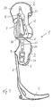
- FIG. 1 is shown in a schematic representation of an orthotic device 1 in the form of a knee-ankle-foot orthosis.
- the orthotic device 1 has an upper part 2 in the form of a thigh structure and a lower part 3 in the form of a lower leg structure.
- the thigh structure 2 and the lower leg structure 3 are pivotally connected to each other via a hinge device 6 about a hinge axis.
- a foot part 4 is fastened via a connecting element 5.
- the connecting element 5 is arranged dorsally on the lower leg structure 3 in a receiving device 9.
- the thigh structure 2 consists of a base body in the form of a receiving tray, which can be fixed via fastening means 21 on a thigh.
- the fastening means are, for example, buckles, straps or Velcro fasteners, which can be placed over an opening in the thigh structure 2 and thus close the thigh structure 2.
- the opening can be frontal or dorsal.
- fastening means 31 are arranged on the lower leg structure, which can be closed frontal below the knee joint to the lower leg.
- the joint devices 6 can be arranged both medially and laterally on the orthotic device 1, the thigh structure 2 and the lower leg structure 3 being fastened to the joint device 6 via joint structure elements 62, 63.
- a control unit 8 for controlling an actuator unit 7 which, based on a program and various sensor data, alters parameters within the actuator unit so as to increase or decrease the damping or to adjust the applied force.
- the actuator unit 7 is designed as a hydraulic or pneumatic actuator unit with a piston and a cylinder.
- the proximal end of a piston rod is arranged at an upper articulation point 72 on the thigh structure 2 and a lower articulation point 73 of an actuator housing as a distal mounting point of the actuator unit 7 at a proximal end of the lower leg structure 3, in the region of the lower articulated structure elements 63.
- the foot part 4 may be integrally formed with the connecting element 5 and be removably attached to the lower part 3 in a receiving device 9, alternatively, the connecting element 5 may also be attached to a separately formed foot part 4.
- the connecting element 5 may also be formed integrally with the lower leg structure 3.
- the actuator unit 7 is arranged only on the lateral side of the orthotic device 1, as an alternative to a lateral and medial arrangement of two joint devices 6 with possibly two actuator units 7.
- the orthosis device 1 according to FIG. 1 shown in frontal view.
- the thigh structure 2 consists of a shell-shaped main body 20, are arranged on the fastening means 21 in the form of straps.
- the lower leg structure 3 is equipped with a main body 30 which can be fixed via the fastening device 31 to the lower leg, not shown, of an orthosis wearer.
- the joint device 6 is arranged laterally and on one side on the orthotic device 1.
- the main body 20, 30 of the thigh structure 2 or lower leg structure 3 are formed dorsal closed.
- the orthotic device 1 is shown in rear view.
- the hinge means 6 is aligned with an anatomical compromise axis of rotation hinge axis 60 about which the upper part 2 and the lower part 3 are mounted to each other pivotally.
- the hinge axis 60 is in the FIG. 3 represented horizontally, which would be the case in reality only exceptionally.
- the actuator 7 is arranged. Based on FIG. 3 It can be seen that the longitudinal extent of the actuator unit 7 extends at an angle ⁇ to the vertical, so that the axes of the proximal and distal actuator suspensions 72, 73 are not parallel to the knee axis.
- This angle ⁇ corresponds to the llio tibia angle, by which the actuator unit 7 has to be swung out of the sagittal plane.
- the pivot axis runs in the anterior-posterior direction.
- the llio tibial angle ⁇ can be up to 30 °, depending on the type of attachment and the anatomical conditions of the orthosis wearer.
- FIGS. 4a and 4b show a schematic representation of an applied orthotic device 1, once in standing position in FIG. 4a and once in a sitting position in FIG. 4b ,
- the orthotic device 1 is shown in simplified form with a thigh splint 22 and a lower thigh splint 32, which are mounted pivotably relative to one another about the articulation device 6.
- the thigh splint 22 is fixed to the thigh via a corresponding fastening device 20, while the lower thigh splint 32 is fixed to the lower leg via the corresponding fastening device 30.
- the thigh splint corresponds to the thigh structure, while the lower leg splint corresponds to the lower leg structure.
- the actuator unit 7 is arranged laterally and dorsally to the rails 22, 32, wherein the upper attachment point 72 of the actuator unit 7 is arranged on the thigh rail 22 and the lower attachment point 73 of the actuator unit 7 on the lower leg rail 32.
- the hinge device 6 simultaneously forms the pivot point of the two rails 22, 32 from each other.
- the lower attachment point 73 which forms the distal bearing point of the actuator unit 7, is spaced dorsal to the pivot point of the hinge device 6, wherein this distance is realized via an obliquely downwardly directed lever.
- the attachment point 73 of the actuator unit 7 is located at a vertical lower leg splint 32 below the pivot point of the hinge device 6.
- FIG. 4b is shown schematically the seated state of an orthosis wearer with applied orthosis.
- the angle between the thigh rail 22 and the lower leg rail 32 is greater than 90 °.
- the actuator unit 7 is arranged laterally next to the thigh of the orthosis wearer. Thereby, it is possible that the leg can be completely bent without the actuator unit 7 becoming an obstacle would represent. Also contributes in such an arrangement of the actuator 7, the orthosis little, so that the most inconspicuous wearing the orthosis is possible.
- the foot part for supporting the foot is not shown. In principle, it is also possible to equip the orthosis 1 without a foot part.
- FIG. 5 shows the basic geometric arrangement of the actuator 7 on the rails 22, 32.
- the hydraulic piston is mounted at its upper end at the upper bearing point 72, for example in a ball and socket joint.
- the support takes place at the lower bearing point 73, which is coupled to the lower lower leg rail 32.
- the thigh splint 22 and the lower thigh splint 32 or the upper part and the lower part of the orthotic device are pivotably coupled together in the joint device 6 about a joint axis.
- the attachment point 73 of the lower storage location is offset by the distance IH dorsal to the pivot point or the axis of rotation of the hinge device 6, so that the two attachment points 72, 73 and the pivot point of the hinge device 6 form a triangle.
- the leg between the lower attachment point 73 and the pivot point 6 is at an angle ⁇ 0 of about 30 ° to the leg, which is formed between the upper attachment point 72 and the pivot point 6 when the orthosis device 1 is stretched. Only after pivoting of the thigh structure 2 or the thigh rail 22 by an angle which corresponds to ⁇ 0 approximately in the direction of flexion is the actuator unit 7 or the leg between the upper attachment point 72 and the lower attachment point 73 perpendicular to the connecting line IH between the lower attachment point 73 and the pivot point of the joint device 6.
- the lever IH between the axis of rotation of the joint device 6 and the adjacent thereto attachment point 73 of the actuator 7 can be realized by two coupled via at least one arm ball joints.
- This angle ⁇ 0 is between 0 ° and 90 °, in particular between 10 ° and 90 ° and preferably between 30 ° and 90 °, and is chosen to correspond to the angle in which the maximum knee moment between the thigh and the lower leg of the orthosis wearer is reached or shall be.
- a schematic course of the knee moment over the flexion angle is in the FIG. 6 shown.
- a progressive damping range between the extended position at 0 ° to the diffraction up to an angle of 35 ° is a progressive damping range, so that even with a linear configuration of the actuator 7, a progressive damping due to the changing geometry is achieved.
- the deviation of the end angle of the progressive damping range of ⁇ 0 results from the variation of the lengths of the actuator unit during the diffraction.
- the knee moment increases up to an angle ⁇ 0, which results from the trigonometric relationships and corresponds approximately to ⁇ 0, until the connecting line between the upper pivot point 72 and the lower pivot point 73 is perpendicular to the connecting line between the lower hinge point 73 and the pivot point of the hinge device. Due to the pure axial force that can oppose the actuator 7 a knee flexion, a maximum knee torque is achieved when the axis of action of the actuator 7 is perpendicular to the connecting line between the pivot point of the hinge device 6 and the lower bearing point 73.
- the knee torque around the sine of the further gift decreases until it comes to a reversal of motion of the actuator unit, so if the diffraction is greater than 90 ° plus ⁇ 0. Then, the knee torque continues to increase with the cosine, provided that the action of the cylinder of the actuator unit or the damper has been switched from pressure to tension.
- Condition 1 is in an extended position of the leg. In position 2, a pivoting by the angle ⁇ took place, so that the maximum knee torque is reached. In the position 3, the axis of action of the actuator unit 7 is located on the connecting line between the lower bearing point 7 and the pivot point of the joint device 6, so that a pivoting angle of 90 ° plus ⁇ is reached. In this position, the effective knee moment is 0 because there is no lever and the actuator force perpendicular to the pivot point of the hinge device 6 extends.
- the damping within the joint orthosis on the basis controlled by sensor data.
- the sensor is preferably arranged in the connecting element 5, which is designed as a dorsal spring, and determines the effective during standing or walking ankle moment.
- the arrangement of the sensor 50 is in the FIG. 8 represented essentially the FIG. 1 with the difference that the sensor 50 is arranged on or in the Dorsalfeder 5, which is designed as a connecting element between the foot part 4 and the lower leg structure 3.
- the sensor 50 transmits the data to the control unit 8, via which in turn valves within the actuator unit 7 are actuated.
- throttle points can be increased or decreased, so that different fluid flows and thus degrees of damping or forces can be realized during the movement. Damping can also be achieved via electrorheological or magnetorheological fluids and a corresponding change in the viscosity of these fluids.
- Such a control of the orthotic device 10 makes it possible, in particular for patients with paralysis, in which the leg is present, but no longer voluntarily controllable that the control of the stance and swing phase can be done while walking.
- the particular hydraulic actuator principle it is possible that any knee-bending or -beugemoment can be generated, whereby a stance phase flexion and an alternating downhill or Treppab obtained and an active support of the movement are made possible. It is important for the acceptance of such an orthotic device that, in addition to the functionality, an optically as inconspicuous design as possible is achieved, in particular an expansion of the orthotic device 1 in the medio-lateral direction must be minimized as far as possible become.
- the sensor 50 for determining the effective forces in the connecting element 5, in particular for determining the ankle moment, can be installed in the connecting element 5.
- FIG. 9 is a schematic cross-sectional view of the embodiment of a sensor 50 with a strain gauge 51 which is mounted on a support, in particular metal support 52.
- the strain gauge 51 is fixed in a conventional manner on the carrier 52, for example glued, and shielded from the environment by separating layers 52.
- the separation layers 53 are fixed to the carrier 52 and may for example consist of a release film or a silicone embedding or coating. These separating layers 53, which are disposed on both the top and the bottom of the carrier 52, prevent shear forces from being transmitted to the carrier 52 and the strain gauges 51 mounted thereon.
- connecting regions 54 of the carrier 52 are provided, at which the carrier 52 can be connected to the surrounding composite material. These connection regions 54 come into connection with the binders of the fiber composite material and thus establish a connection to the fiber materials.
- FIG. 10 is shown in a schematic side view of the connecting element 5, for example in the form of a beam spring element.
- a sensor 50 is laminated with a shielded strain gauge 51 on a support 52 each. Cable 56, which are connected to the strain gauge 51, lead out of the connecting element 5 and to an evaluation unit or the control device 8.
- the carrier 52 is preferably formed thin, for example between 0.1 mm and 0.5 mm, so that the entire Arrangement of the sensor 50 with the strain gauges 51 and separating layers 53 has a thickness of less than 1 mm.
- the sensitivity of the sensors can be adjusted by the position within the connecting element 5, the change resulting from the variation of the distance to the neutral fiber 55.
- FIGS. 11 and 12 A variant of the invention is in the FIGS. 11 and 12 shown, in which on both sides of the carrier 52 strain gauges 51 are arranged and surrounded by separating layers 53.
- connecting regions 54 are provided in addition to the separating layers 53 in order to be laminated into the connecting element 5.
- FIG. 12 is a sectional view of the arrangement of the sensor 50 according to FIG. 11 shown within the connecting element 5.
- the arrangement of the sensor 50 takes place in the neutral fiber 55 of the connecting element 5, the cables 56 lead out of the connecting element 5.
- the carrier 52 bends together with the connecting element 5 and generates an output signal.
- strain gauges 51 immediately adjacent to the neutral fiber 55, a high amplification factor is required, but there is the advantage that only a single foreign body has to be arranged within the composite element 5.
- This foreign body in the form of the sensor 50 can be easily inserted and laminated as a completely prefabricated module, which optionally includes an electronic circuit for signal amplification and signal conditioning.
- the connecting element 5 is designed as a dorsal spring in order to increase the energy efficiency for the orthosis wearer.
- the dorsal spring 5, as well as the attached thereto or molded foot 4 consist of a fiber-reinforced, elastic structure, for example, a carbon structure, which absorb the energy of the contact shock at the heel contact and give the recorded energy again during the swing phase introduction, whereby the introduction of the swing phase facilitates becomes.
- the actuator unit 7 On the basis of the sensor data determined, for example the ankle moment or the load heights and load directions which are effective within the respective structure, it is possible to make different settings in the actuator unit 7.
- the knee angle that is to say the bending angle between the thigh structure 2 and the lower leg structure 3, can be measured either via a protractor arranged directly on the articulation device 6 or with the aid of sensors which measure the position of the respective components relative to an orthosis-independent direction component, for example relative to the gravity component or horizontal.
- sensors for measuring knee moments or Axialkraftbelastonne be provided to further improve the control capabilities of the actuator.
- the ankle moment during the stance phase passes through a typical time course.
- the spring element 5 is first deformed, ie "charged” with energy, and then the spring 5 relaxes again, so energy is given off
- a typical course results for the knee angle and for the knee moment, via the actuator unit 7, in particular via the Aktuatorhydraulik, can be influenced, whereby the time course of the energy stored in the spring 5 can be influenced within certain limits.
- the actuator unit 7 is preferably equipped as a linear, hydraulic damper unit.
- the damping can be adjusted separately via two valves for extension and flexion, whereby the valves are adjusted via servomotors and an optionally interposed transmission.
- the receiving shells 20, 30 of the thigh and lower leg structures 2, 3 preferably also consist of a carbon fiber material in order to be able to absorb high forces without requiring a large amount of space and rendering the orthotic device 1 too heavy.
- the actuator unit 7 generates braking moments by converting kinetic energy into heat. With the orthotic device 1, it is possible to go at different speeds in the plane, ramps or stairs with different slopes and occupy different seating positions.
Abstract
Description
Die Erfindung betrifft eine Knieorthese mit einer Oberschenkelstruktur, insbesondere Oberschenkelschiene, die eine Befestigungseinrichtung zur Festlegung an einem Oberschenkel aufweist, einer Unterschenkelstruktur, insbesondere Unterschenkelschiene, die über eine Gelenkeinrichtung mit der Oberschenkelstruktur verschwenkbar gekoppelt ist und eine Befestigungseinrichtung zur Festlegung an einem Unterschenkel sowie ggf. ein Fußteil zur Abstützung eines Fußes aufweist, und einer Aktuatoreinheit zwischen der Oberschenkelstruktur und der Unterschenkelstruktur sowie ein Verfahren zum Steuern einer solchen Knieorthese.The invention relates to a knee orthosis with a thigh structure, in particular thigh rail, which has a fastening device for fixing to a thigh, a lower leg structure, in particular lower leg rail, which is pivotally coupled via a hinge device with the thigh structure and a fastening device for fixing to a lower leg and possibly a Foot part for supporting a foot, and an actuator unit between the thigh structure and the lower leg structure and a method for controlling such a knee brace.
Knieorthesen werden zur Unterstützung oder zum Ersetzen einer Funktion eines Beines eingesetzt. Die Orthesen bilden einen äußeren Rahmen oder Teilrahmen und werden an dem Bein angelegt. Bei Verletzungen der Bänder oder der Muskulatur sowie Lähmungen dienen Orthesen zu einer Gelenkstabilisierung sowie ggf. zu einer Begrenzung des Beugewinkels oder Streckwinkels der über das Kniegelenk verbundenen Schenkelteile. In der Regel weisen die Knieorthesen je eine Schiene für den Oberschenkel und den Unterschenkel auf und werden über Befestigungseinrichtungen, wie Schnallen oder Riemen, an dem Ober- und Unterschenkel festgelegt.Knee braces are used to support or replace a leg function. The orthoses form an outer frame or subframe and are applied to the leg. In the case of injuries of the ligaments or the musculature as well as paralyzes, orthoses serve for joint stabilization as well as possibly for a limitation of the flexion angle or angle of extension of the leg parts connected via the knee joint. Typically, the knee braces each have a thigh and shin splint and are secured to the thigh and lower leg via fasteners such as buckles or straps.
Bei Lähmungen des Beines oder bei entsprechenden Verletzungen ist es vorgesehen, dass auch der Fuß innerhalb der Orthese fixiert wird. Dazu ist eine Fußschale vorgesehen, die an der Unterschenkelstruktur befestigt oder daran ausgebildet ist.In the case of paralysis of the leg or in the case of corresponding injuries, it is envisaged that the foot will also be fixed within the orthosis. For this purpose, a foot shell is provided which is attached to the lower leg structure or formed thereon.
Die
Die
Die
Die 299 14 375 U1 beschreibt ein Orthesengelenk mit einer Oberschenkelschiene und einer Unterschenkelschiene, die einseitig über einen oder mehrere gemeinsame Zapfen oder durch endseitige Verzahnungen im Orthesengelenk miteinander in Eingriff stehen. In dem Orthesengelenk sind Endanschläge vorhanden, die über einen Winkelbereich einstellbar sind. Bei Beugung oder Streckung in dem Orthesengelenk kann eine konstante oder dynamische Bremsung ausgeübt werden, die pneumatisch, hydraulisch oder durch ein elastisches Element erfolgt. Die Bremsung erfolgt insbesondere über elastische Anschläge.The 299 14 375 U1 describes an orthotic joint with a thigh splint and a lower leg splint which engage on one side via one or more common spigots or through end-to-end splines in the orthotic joint. In the orthotic joint end stops are available, which are adjustable over an angular range. In flexion or extension in the orthotic joint, a constant or dynamic braking can be exercised, which takes place pneumatically, hydraulically or by an elastic element. The braking is done in particular via elastic stops.
Die
Die teilweise sehr komplexen Vorrichtungen benötigen viel Platz, insbesondere in medio-lateraler Ausrichtung. Aufgabe der vorliegenden Erfindung ist es, eine Knieorthese bereitzustellen, mit der neben einer ausreichenden Funktionalität auch eine erhöhte kosmetische Qualität erreicht werden kann.The sometimes very complex devices require a lot of space, especially in medio-lateral alignment. The object of the present invention is to provide a knee brace with which not only sufficient functionality but also increased cosmetic quality can be achieved.
Erfindungsgemäß wird diese Aufgabe durch eine Knieorthese mit den Merkmalen des Anspruchs 1 und ein Verfahren zum Steuern einer Knieorthese mit den Merkmalen des Anspruchs 18 gelöst. Vorteilhafte Ausgestaltungen und Weiterbildungen der Erfindung sind in den jeweiligen Unteransprüchen beschrieben.According to the invention, this object is achieved by a knee brace with the features of
Die erfindungsgemäße Knieorthese mit einer Oberschenkelstruktur, die eine Befestigungseinrichtung zur Festlegung an einem Oberschenkel aufweist, einer Unterschenkelstruktur, die über eine Gelenkeinrichtung mit der Oberschenkelstruktur verschwenkbar gekoppelt ist und eine Befestigungseinrichtung zur Festlegung an einem Unterschenkel sowie ggf. ein Fußteil zur Abstützung eines Fußes aufweist, und einer Aktuatoreinheit zwischen der Oberschenkelstruktur und der Unterschenkelstruktur sieht vor, dass die Befestigungspunkte des Aktuators an den Schienen und der Drehpunkt der Gelenkeinrichtung ein Dreieck ausbilden und die Befestigungspunkte dergestalt an den Schienen angeordnet sind, dass in einer Kniewinkelstellung im Bereich einer Unterschenkelbeugung zwischen 0° und 90°, insbesondere 10° und 90°, bevorzugt zwischen 30° und 90° zu dem Oberschenkel die Verbindungslinie zwischen den Befestigungspunkten senkrecht auf einer Verbindungslinie zwischen einem Befestigungspunkt und dem Drehpunkt steht. Die Abstände zwischen den Befestigungspunkten der Aktuatoreinheit an den Schienen und dem Drehpunkt der Gelenkeinrichtung sind feststehend. Durch eine Relativbewegung der Befestigungspunkte zueinander aufgrund der Verschwenkung der Oberschenkelstruktur relativ zu der Unterschenkelstruktur verändert sich jedoch die Länge der Aktuatoreinheit, beispielsweise eines Hydraulkdämpfers oder eines hydraulischen Antriebs. Durch eine entsprechende Anordnung der Befestigungspunkte an den Schienen ist es möglich, eine kniewinkelabhängige Momentencharakteristik der Knieorthese auch bei einer konstanten Dämpfung der linearen Aktuatoreinheit bereitzustellen. Dies geschieht über eine Anordnung und Ausgestaltung einer Hebellänge in einem bestimmten Winkel zur Normalen der anderen Schiene, also beispielsweise dem Hebel an der Unterschenkelstruktur im Verhältnis zur Normalen der Oberschenkelstruktur, die durch den Drehpunkt der Gelenkeinrichtung hindurch geht. Über den entsprechenden Winkel wird festgelegt, wie sich die effektive Hebellänge für den Aktuator oder Dämpfer, abhängig von dem Kniewinkel, ändert. Dadurch kann der Kniewinkel, bei dem das erzeugbare Widerstandsmoment oder die übertragbaren Kräfte maximal sind, eingestellt werden. Somit ergibt sich ein angepasster Kraftwirkungs- oder Widerstandsmomentenverlauf mit einem nicht linearen Zusammenhang, so dass sich aufgrund der biomechanischen Hebelverhältnisse eine maximale Unterstützung des Beines bei einem gebeugten Bein erreichen lässt, wobei die von dem Aktuator aufgebrachte Kraft konstant gelassen werden kann. Eine maximale Unterstützung des Beines erfolgt somit dann, wenn die Belastung auf die Gelenkeinrichtung bzw. auf das Kniegelenk sehr groß ist, beispielsweise bei einer Winkelstellung des Oberschenkels zum Unterschenkel von 35° bis 45°. Es ist aber auch vorgesehen, bei einer geringeren oder höheren Beugung das maximale Widerstandsmoment oder die maximale Aktuatorkraft bereitzustellen, sofern dies erforderlich oder vom Patienten gewünscht ist. Aufgrund des nicht linearen Verlaufes des Widerstandsmomentes trotz einer konstanten Dämpfung in der Aktuatoreinheit ergibt sich insbesondere im Bereich der Standphasenflexion eine progressive Dämpfung und damit eine progressive Standphasendämpfung, die ohne eine aufwendige Steuerungsmechanik und Sensorik realisiert werden kann, wenn der Aktuator als linear wirkender Dämpfer ausgebildet ist. Entsprechendes gilt für die Ausgestaltung des Aktuators als Antrieb. Von dem Patienten wird ein progressiver Verlauf der Widerstandsmomente in der Standphasenflexion als angenehm beschrieben, da kein spontanes Wegknicken des Kniegelenkes befürchtet werden muss.The knee orthosis according to the invention with a thigh structure having a fastening device for fixing to a thigh, a lower leg structure which is pivotally coupled via a hinge device with the thigh structure and a fastening device for fixing to a lower leg and possibly a foot part for supporting a foot, and An actuator unit between the thigh structure and the lower leg structure provides that the attachment points of the actuator to the rails and the pivot point of the joint device forming a triangle and the attachment points are arranged on the rails such that in a knee angle position in the region of a lower leg flexion between 0 ° and 90 °, in particular 10 ° and 90 °, preferably between 30 ° and 90 ° to the thigh, the line of connection between the attachment points perpendicular to a connecting line between an attachment point and the D rehpunkt stands. The distances between the attachment points of the actuator unit to the rails and the pivot point of the hinge device are fixed. By a relative movement of the attachment points to each other due to the pivoting of the thigh structure However, relative to the lower leg structure, the length of the actuator unit, for example a hydraulic damper or a hydraulic drive, changes. By a corresponding arrangement of the attachment points on the rails, it is possible to provide a knee-angle-dependent moment characteristic of the knee orthosis even with a constant damping of the linear actuator unit. This is done via an arrangement and configuration of a lever length at a certain angle to the normal of the other rail, so for example the lever on the lower leg structure in relation to the normal of the thigh structure, which passes through the pivot point of the hinge device. The appropriate angle determines how the effective lever length for the actuator or damper changes, depending on the knee angle. As a result, the knee angle at which the producible moment of resistance or the transferable forces are maximum can be adjusted. This results in an adapted force action or resistance torque curve with a non-linear relationship, so that maximum support of the leg can be achieved with a bent leg due to the biomechanical leverage ratios, whereby the force applied by the actuator force can be left constant. A maximum support of the leg thus takes place when the load on the joint device or on the knee joint is very large, for example, at an angular position of the thigh to the lower leg of 35 ° to 45 °. However, it is also provided to provide the maximum resistance moment or the maximum actuator force at a lower or higher diffraction, if required or desired by the patient. Due to the non-linear course of the resistive torque despite a constant damping in the actuator results in particular in the field of Standphasenflexion a progressive damping and thus a progressive stance phase damping, which can be realized without a complex control mechanism and sensors, if the actuator is designed as a linear-acting damper , The same applies to the configuration of the actuator as a drive. From the patient, a progressive course of the resistance moments in the stance phase flexion is described as pleasant, since no spontaneous buckling of the knee joint must be feared.
Eine Weiterbildung der Erfindung sieht vor, dass der Aktuator ein hydraulischer Dämpfer ist, wobei die Ventile oder Steuereinrichtung des Hydraulikdämpfers in Gehrichtung vor und/oder hinter einer Kolbenzylinderanordnung angeordnet sind. Durch diese Anordnung der Ventile und Steuereinrichtungen sowie der Überströmkanäle ist es möglich, einen relativ schmal bauenden Dämpfer bereitzustellen, so dass die Komponenten in medio-lateraler Ausrichtung wenig auftragen. Dies führt zu einer erhöhten Akzeptanz der Orthese, da diese unter normaler Kleidung getragen werden kann. Die Aktuatoreinheit ist insbesondere als linearer Dämpfer ausgebildet, wodurch sich die gesamte Knieorthese einfacher und preiswerter herstellen lässt.A further development of the invention provides that the actuator is a hydraulic damper, the valves or control device of the hydraulic damper being arranged in the direction of travel in front of and / or behind a piston-cylinder arrangement. By this arrangement of the valves and control devices as well as the overflow channels, it is possible to provide a relatively narrow damper, so that the components apply little in medio-lateral orientation. This leads to an increased acceptance of the orthosis, since it can be worn under normal clothing. The actuator unit is designed, in particular, as a linear damper, as a result of which the entire knee orthosis can be produced more simply and inexpensively.
Die Aktuatoreinheit ist bevorzugt seitlich neben dem Ober- oder Unterschenkel angeordnet, bevorzugt neben dem Oberschenkel, wobei eine Anordnung an der Orthese in Gehrichtung hinter den Schienen bevorzugt wird. Dadurch kann die Hydraulikeinrichtung ohne Umlenkeinrichtungen auf Druck belastet werden, wobei durch die Anordnung der Befestigungspunkte des Aktuators an den Schienen leicht eine Anpassung an die gewünschte Momentencharakteristik erfolgen kann. Beispielsweise können mehrere Befestigungspunkte an einer Schiene angeordnet sein, um so die Momentencharakteristik individuell anpassen zu können.The actuator unit is preferably arranged laterally next to the upper or lower leg, preferably next to the thigh, wherein an arrangement on the orthosis in the direction of travel behind the rails is preferred. As a result, the hydraulic device can be subjected to pressure without deflection devices, whereby the arrangement of the attachment points of the actuator on the rails makes it easy to adapt to the desired torque characteristic. For example, a plurality of attachment points may be arranged on a rail so as to be able to individually adapt the moment characteristic.
Eine Weiterbildung der Erfindung sieht vor, dass die Aktuatoreinheit an zumindest einem Befestigungspunkt über eine Lagerung mit mindestens zwei Freiheitsgraden gelagert. Speziell ist vorgesehen, dass der Aktuator an zumindest einem Befestigungspunkt über eine kardanische Lagerung mit sich schneidenden oder sich nicht schneidenden Achsen gelagert ist. Aufgrund der individuellen Ausgestaltung der jeweiligen Orthese, die an den Patienten angepasst werden muss, kommt es zu Fluchtungsfehlern bei den Bewegungsachsen, sowohl hinsichtlich der Gelenkachse als auch der Achsen an den Befestigungspunkten, so dass der Zylinder der Aktuatoreinheit sich auf einer Kegelmantelfläche bewegt. Da insbesondere ein Hydraulikdämpfer nur axiale Lasten aufnehmen sollte, um die Haltbarkeit der Aktuatoreinheit zu gewährleisten, ist eine kardanische Lagerung an zumindest einem Befestigungspunkt vorgesehen, idealerweise ist eine Lagerung mit zwei Freiheitsgraden an beiden Lagerungsstellen vorgesehen. Aufgrund der hohen, zu übertragenden hydraulischen Kräfte müsste eine herkömmliche kardanische Lagerung mit sich schneidenden Achsen sehr massiv ausgeführt werden. Aufgrund des limitierten Bauraumes ist es jedoch vorgesehen, die kardanische Lagerung aufzulösen und die Achsen sich nicht schneiden zu lassen. Dies bringt Vorteile für das Design des Gelenkes mit sich, da Kollisionen zwischen der Hydraulik und einem Lagerblock leichter vermieden werden können.A development of the invention provides that the actuator unit is mounted on at least one attachment point via a bearing with at least two degrees of freedom. Specifically, it is provided that the actuator is mounted on at least one attachment point via a gimbal bearing with intersecting or non-intersecting axes. Due to the individual design of the respective orthosis, which must be adapted to the patient, there are alignment errors in the axes of movement, both with respect to the hinge axis and the axes at the attachment points, so that the cylinder of the actuator moves on a conical surface. In particular, since a hydraulic damper should only support axial loads to ensure the durability of the actuator unit, a gimbal is Storage provided at least one attachment point, ideally, a storage with two degrees of freedom is provided at both storage locations. Due to the high hydraulic forces to be transmitted, a conventional gimbal bearing with intersecting axes would have to be made very solid. Due to the limited installation space, however, it is intended to dissolve the gimbal bearing and not let the axes cut. This brings benefits to the design of the joint, as collisions between the hydraulics and a bearing block can be more easily avoided.
Weiterhin ist es möglich, an dem Verbindungsteil zwischen den Achsen die Hydraulikkraft, die vom Kniemoment abhängt, zu messen, wobei diese Messgröße beispielsweise zur Steuerung des Aktuators eingesetzt werden kann. Mit einer solchen Gelenklagerung ist es möglich, die auftretenden, sehr hohen hydraulischen Kräfte aufzunehmen und gleichzeitig die Baugrößen gering zu halten. Alternativ dazu ist vorgesehen, dass zumindest eine der Lagerstellen als eine Kugelgelenklagerung ausgebildet ist, um einerseits eine geringe Bauhöhe und andererseits ein rein punktuelle, axiale Krafteinleitung in die Aktuatoreinheit zu erreichen. Störende Biegemomente, insbesondere für eine Kolben-Zylinder-Hydraulik störende Momente, können dadurch ausgeschlossen oder verringert werden.Furthermore, it is possible to measure at the connecting part between the axes of the hydraulic force, which depends on the knee torque, this measure can be used for example to control the actuator. With such a hinge bearing, it is possible to absorb the occurring, very high hydraulic forces and at the same time keep the sizes low. Alternatively, it is provided that at least one of the bearing points is designed as a ball joint bearing, on the one hand to achieve a low overall height and, on the other hand, a purely punctual, axial introduction of force into the actuator unit. Disturbing bending moments, especially for a piston-cylinder hydraulic disturbing moments, can be excluded or reduced.
Eine verbesserte Anpassung an die anatomischen Gegebenheiten wird erreicht, wenn der Aktuator in der Lateralebene um einen bestimmten Winkel verkippt angeordnet ist. Dadurch kann der Aktuator oder Hydraulikdämpfer an dem Oberschenkel dicht anliegend montiert werden.An improved adaptation to the anatomical conditions is achieved when the actuator is tilted in the lateral plane by a certain angle. As a result, the actuator or hydraulic damper can be mounted tightly against the thigh.
Ergänzend oder auch in Alleinstellung kann das Fußteil eine Dorsalfeder aufweisen, an der oder in der zumindest ein Sensor zur Erfassung der wirksamen Kräfte, z.B. der Biegebelastung und dadurch zur Erfassung des Knöchelmomentes angeordnet ist. Diese Sensordaten können genutzt werden, um die Wirkung der Dämpfereinheit über einen Aktuator zu verändern und die Dämpfung zusätzlich zu der konstruktiven Dämpfungscharakteristitk zu verändern. Bei Ausgestaltung der Aktuatoreinheit als Antrieb oder einer Kombination aus Antrieb und Dämpfer werden die Daten genutzt, um das Verhalten der Aktuatoreinheit zu verändern. Ebenfalls können ein Kniewinkelsensor, Kniemomentsensor sowie ein Absolutwinkelsensor zur Erfassung der Orientierung zumindest einer der Schienen im Raum einer Orthese angebracht sein. Die Daten der Sensoren können zusammen oder separat zur Steuerung der Aktuatoreinheit genutzt werden. Eine solche Anordnung von Sensoren zur Steuerung der Widerstandsmomentenverläufe oder des Verhaltens der Aktuatoreinheit kann auch unabhängig von der oben beschriebenen geometrischen Anordnung der Aktuatoreinheit eingesetzt werden.In addition or in isolation, the foot part may have a dorsal spring on or in which at least one sensor for detecting the effective forces, for example the bending load and thereby for detecting the ankle moment is arranged. This sensor data can be used to alter the action of the damper unit via an actuator and alter the damping in addition to the structural damping characteristic. In the embodiment of the actuator unit as drive or a combination of drive and damper, the data is used to change the behavior of the actuator unit. Likewise, a knee angle sensor, knee moment sensor and an absolute angle sensor for detecting the orientation of at least one of the rails may be mounted in the space of an orthosis. The data from the sensors can be used together or separately to control the actuator unit. Such an arrangement of sensors for controlling the resistance torque curves or the behavior of the actuator unit can also be used independently of the above-described geometric arrangement of the actuator unit.
Die Steuereinrichtung zur Veränderung des Verhaltens der Aktuatoreinheit ist mit den Sensoren gekoppelt und dient zur Veränderung z.B. des Dämpferwiderstandes oder der aufgebrachten Kraft in der Aktuatoreinheit.The control means for varying the behavior of the actuator unit is coupled to the sensors and serves to change e.g. the damper resistance or the applied force in the actuator unit.
Es kann eine Gelenkskinematik vorgesehen sein, über die die Aktuatoreinheit an der Ober- und/oder Unterschenkelstruktur angelenkt ist. Die Aktuatoreinheit kann auch unmittelbar an der Ober- und/oder Unterschenkelstruktur angelenkt sein, wobei in beiden Fällen vorgesehen ist, dass eine Verschwenkbarkeit und/oder Verlagerbarkeit der Gelenkskinematik bzw. der Aktuatoreinheit gegeben ist. Die Verschwenkbarkeit oder Verlagerbarkeit ist in der Lateralebene gegeben, wobei die Befestigungspunkte der Aktuatoreinheit an der Ober- und Unterschenkelstruktur und der Drehpunkt der Gelenkseinrichtung weiterhin ein Dreieck ausbilden.It can be provided a joint kinematics, via which the actuator unit is articulated to the upper and / or lower leg structure. The actuator unit can also be articulated directly on the upper and / or lower leg structure, wherein it is provided in both cases that a pivotability and / or displaceability of the joint kinematics or the actuator unit is given. The pivoting or displaceability is given in the lateral plane, wherein the attachment points of the actuator unit on the upper and lower leg structure and the pivot point of the joint device continue to form a triangle.
Die Bewegungsachse der Orthese zwischen der Ober- und Unterschenkelstruktur kann durch die Mittelpunkte zweier Kugelgelenke festgelegt werden, wenn die Ober- und Unterschenkelstruktur über Kugelgelenke miteinander verbunden sind. Alternativ können die Ober- und Unterschenkelstruktur auch über ein Kardangelenk miteinander verbunden sein.The axis of movement of the orthosis between the upper and lower leg structure can be defined by the centers of two ball joints, when the upper and lower leg structure are connected to each other via ball joints. Alternatively, the upper and lower leg structure can also be connected to one another via a universal joint.
Der Schwenkwinkel der Gelenksmechanik in der Lateralebene kann durch ein Mitläufergelenk festgelegt werden, bei dem es sich um eine Scharnier-, Kardan- oder Kugelgelenk handeln kann.The pivot angle of the joint mechanism in the lateral plane can be defined by a idler joint, which is a hinge, gimbal or ball joint can act.
Der Hebel zwischen der Drehachse der Gelenkeinrichtung und dem dazu benachbarten Befestigungspunkt der Aktuatoreinheit kann durch zwei über mindestens einen Lenker gekoppelte Kugelgelenke realisiert werden.The lever between the axis of rotation of the hinge device and the adjoining attachment point of the actuator unit can be realized by two coupled via at least one arm ball joints.
Das Verfahren zur Steuerung einer Knieorthese mit einer Oberschenkelstruktur, einer Gelenkeinrichtung und einer Unterschenkelstruktur, die ein Fußteil aufweist, sieht vor, dass ein wirksames Moment, insbesondere Knöchelmoment, innerhalb der Orthese bestimmt und der Widerstand der Aktuatoreinheit in Abhängigkeit von dem Moment, insbesondere Knöchelmoment verändert wird. Ergänzend oder alternativ kann die Aktuatoreinheit in Abhängigkeit von einem gemessenen oder errechneten Kniemoment, dem Kniewinkel, also der Stellung von Oberschenkelstruktur und Unterschenkelstruktur zueinander, oder von der Raumorientierung zumindest einer Oberschenkel- oder Unterschenkelstruktur verändert werden. Dadurch ist es möglich, eine Kontrolle der Stand-und Schwungphase bei Patienten mit Lähmungen, bei denen das Bein nicht mehr willentlich kontrollierbar ist, zur Verfügung zu stellen. Durch das veränderliche Widerstandsmoment, beispielsweise über einen hydraulischen Aktuator, kann jedes beliebige Kniemoment generiert werden, wodurch Standphasenflexion und alternierendes Bergab- und Treppabgehen ermöglicht werden. Bei aktiven Aktuatoreinheiten kann eine entsprechende Unterstützung der Bewegung gezielt und effizient erfolgen.The method for controlling a knee brace having a thigh structure, a hinge device, and a lower leg structure having a foot portion provides that an effective moment, particularly ankle moment, is determined within the brace and the resistance of the actuator unit changes depending on the moment, particularly the ankle moment becomes. Additionally or alternatively, the actuator unit can be changed depending on a measured or calculated knee moment, the knee angle, ie the position of thigh structure and lower leg structure to each other, or the spatial orientation of at least one thigh or lower leg structure. This makes it possible to provide control of the stance and swing phase in patients with paralysis where the leg is no longer voluntarily controllable. Due to the variable resistance moment, for example via a hydraulic actuator, any knee moment can be generated, thereby enabling stand-phase flexion and alternating downhill and downhill stairs. With active actuator units, a corresponding support of the movement can be targeted and efficient.
Eine Weiterbildung der Erfindung sieht vor, dass die innerhalb der Orthese generierten Sensorsignale zusätzlich zur Erzeugung von Impulsen zur funktionellen Elektrostimulation der verbliebenen Restmuskulatur verwendet werden. Hierbei werden die von der Orthese ermittelten Messwerte zur Festlegung der Stärke bzw. des Timings der Stimulationsimpulse einer mit dem Steuergerät verbundenen Einheit für funktionelle Elektrostimulation verwendet. Damit können die verbliebenen Muskeln gezielt aktiviert werden, um den Bewegungsablauf zu verbessern und die Aktuatoreinrichtung zu unterstützen oder zu ersetzen.A development of the invention provides that the sensor signals generated within the orthosis are used in addition to the generation of pulses for the functional electrical stimulation of the remaining residual muscle. In this case, the measured values ascertained by the orthosis are used to determine the strength or the timing of the stimulation pulses of a unit for functional electrostimulation connected to the control unit. In this way, the remaining muscles can be specifically activated in order to improve the movement sequence and to support or replace the actuator device.
Nachfolgend wird ein Ausführungsbeispiel der Erfindung anhand der beigefügten Figuren näher erläutert. Es zeigen:
-
Figur 1 - eine schematische Seitenansicht einer Knie-Knöchel-Fuß-Orthese in Seitenansicht; -
Figur 2 - eine schematische Darstellung der Orthese in Frontalansicht; -
Figur 3 - eine Ortheseneinrichtung in Dorsalansicht; -
Figuren 4a und 4b - schematische Orthesendarstellungen stehend und sitzend; -
Figur 5 - eine Prinzipskizze der Aktuatoreinheitanordnung; -
Figur 6 - ein Momentenverlauf über die Kniebeugung; -
Figur 7 - Positionen der Aktuatoreinheit bei verschiedenen Beugewinkeln; -
Figur 8 - eineVariante der Figur 1 ; -
Figur 9 - einen Sensor auf einer Trägerplatte; -
Figur 10 - ein Anordnungsbeispiel vonSensoren gemäß Figur 9 in einem Verbindungselement; -
Figur 11 - eine Variante desSensors gemäß Figur 9 ; sowie -
Figur 12 - ein Anordnungsbeispiel desSensors gemäß Figur 11 .
-
FIG. 1 - A schematic side view of a knee-ankle-foot orthosis in side view; -
FIG. 2 a schematic representation of the orthosis in a front view; -
FIG. 3 - An orthosis device in dorsal view; -
FIGS. 4a and 4b - schematic Orthesendarstellungen standing and sitting; -
FIG. 5 a schematic diagram of the actuator unit arrangement; -
FIG. 6 - a moment course over the knee flexion; -
FIG. 7 Positions of the actuator unit at different bend angles; -
FIG. 8 a variant ofFIG. 1 ; -
FIG. 9 a sensor on a carrier plate; -
FIG. 10 - An arrangement example of sensors according toFIG. 9 in a connecting element; -
FIG. 11 - A variant of the sensor according toFIG. 9 ; such as -
FIG. 12 - An arrangement example of the sensor according toFIG. 11 ,
In der
Die Oberschenkelstruktur 2 besteht aus einem Grundkörper in Gestalt einer Aufnahmeschale, die über Befestigungsmittel 21 an einem Oberschenkel festgelegt werden kann. Die Befestigungsmittel sind beispielsweise Schnallen, Laschen oder Klettverschlüsse, die über eine Öffnung innerhalb der Oberschenkelstruktur 2 gelegt werden können und so die Oberschenkelstruktur 2 verschließen. Die Öffnung kann frontal oder dorsal sein. Ebenfalls sind an der Unterschenkelstruktur Befestigungsmittel 31 angeordnet, die sich frontal unterhalb des Kniegelenkes um den Unterschenkel schließen lassen.The
Die Gelenkeinrichtungen 6 können sowohl medial als auch lateral an der Ortheseneinrichtung 1 angeordnet sein, wobei die Oberschenkelstruktur 2 und die Unterschenkelstruktur 3 über Gelenkstrukturelemente 62, 63 an der Gelenkeinrichtung 6 befestigt sind. An der Unterschenkelstruktur 3 ist ein Steuergerät 8 zur Steuerung einer Aktuatoreinheit 7 angeordnet, die auf Grundlage eines Programmes und verschiedener Sensordaten Parameter innerhalb der Aktuatoreinheit verändert, um so die Dämpfung zu erhöhen oder zu verringern oder die aufgebrachte Kraft anzupassen. Alternativ zu der Anbringung der Steuereinheit 8 an dem Unterschenkelstruktur 3 kann diese auch an der Oberschenkelstruktur 2 angeordnet sein. Die Aktuatoreinheit 7 ist als eine hydraulische oder pneumatische Aktuatoreinheit mit einem Kolben und einem Zylinder ausgebildet. Im dargestellten Ausführungsbeispiel ist das proximale Ende einer Kolbenstange an einem oberen Anlenkpunkt 72 an der Oberschenkelstruktur 2 und ein unterer Anlenkpunkt 73 eines Aktuatorgehäuses als distaler Lagerungspunkt der Aktuatoreinheit 7 an einem proximalen Ende der Unterschenkelstruktur 3 angeordnet, im Bereich der unteren Gelenkstrukturelemente 63. Das Fußteil 4 kann einstückig mit dem Verbindungselement 5 ausgebildet und auswechselbar an dem Unterteil 3 in einer Aufnahmeeinrichtung 9 befestigt sein, alternativ kann das Verbindungselement 5 auch an einem separat ausgebildeten Fußteil 4 befestigt sein. Das Verbindungselement 5 kann auch einstückig mit der Unterschenkelstruktur 3 ausgebildet sein.The
In dem dargestellten Ausführungsbeispiel ist die Aktuatoreinheit 7 nur an der lateralen Seite der Ortheseneinrichtung 1 angeordnet, als Alternative zu einer lateralen und medialen Anordnung zweier Gelenkeinrichtungen 6 mit ggf. zwei Aktuatoreinheiten 7.In the exemplary embodiment illustrated, the
In der
In der
Die
In der
Die
Zu Beginn der Beugung, also über die ersten 35° Beugewinkel, steigt das Kniemoment bis zu einem Winkel φ0, der sich aufgrund der trigonometrischen Beziehungen ergibt und in etwa φ0 entspricht, an, bis die Verbindungslinie zwischen dem oberen Gelenkpunkt 72 und dem unteren Gelenkpunkt 73 senkrecht auf der Verbindungslinie zwischen dem unteren Gelenkpunkt 73 und dem Drehpunkt der Gelenkeinrichtung liegt. Aufgrund der reinen Axialkraft, die die Aktuatoreinheit 7 einer Kniebeugung entgegen setzen kann, wird ein maximales Kniemoment dann erreicht, wenn die Wirksachse der Aktuatoreinheit 7 senkrecht auf der Verbindungslinie zwischen dem Drehpunkt der Gelenkeinrichtung 6 und dem unteren Lagerpunkt 73 steht. Bei einer weiteren Beugung des Knies verringert sich das Kniemoment um den Sinus der weiteren Verschenkung, bis es zu einer Bewegungsumkehr der Aktuatoreinheit kommt, also wenn die Beugung größer als 90° plus φ0 ist. Dann steigt das Kniemoment mit dem Kosinus weiter an, sofern die Wirkung des Zylinders der Aktuatoreinheit oder des Dämpfers von Druck auf Zug umgeschaltet wurde.At the beginning of the diffraction, ie over the first 35 ° flexion angle, the knee moment increases up to an angle φ0, which results from the trigonometric relationships and corresponds approximately to φ0, until the connecting line between the
In der
Neben der Beeinflussung des Momentenverlaufes aufgrund der konstruktiven Ausgestaltung und Anordnung der Aktuatoreinheit 7 innerhalb der Gelenkorthese 1 und die spezielle Anordnung der Lagerungspunkte 72, 73 relativ zu dem Drehpunkt der Gelenkeinrichtung 6 bzw. zu der Gelenkachse 60, kann die Dämpfung innerhalb der Gelenkorthese auf der Grundlage von Sensordaten kontrolliert werden. Der Sensor ist dabei bevorzugt in dem Verbindungselement 5, das als Dorsalfeder ausgebildet ist, angeordnet und ermittelt das während des Stehens oder Gehens wirksame Knöchelmoment. Die Anordnung des Sensors 50 ist dabei in der
Eine solche Steuerung der Ortheseneinrichtung 10 ermöglicht es insbesondere für Patienten mit Lähmungen, bei denen das Bein vorhanden, jedoch nicht mehr willentlich kontrollierbar ist, dass die Kontrolle der Stand- und Schwungphase während des Gehens erfolgen kann. Durch das insbesondere hydraulische Aktuatorprinzip ist es möglich, dass jedes beliebige Kniedämpfungs- oder -beugemoment generiert werden kann, wodurch eine Standphasenflexion und ein alternierendes Bergab- oder Treppabgehen und eine aktive Unterstützung der Bewegung ermöglicht werden. Dabei ist für die Akzeptanz einer solchen Ortheseneinrichtung wichtig, dass neben der Funktionalität auch ein optisch möglichst unauffälliges Design erreicht wird, insbesondere muss eine Ausdehnung der Ortheseneinrichtung 1 in medio-lateraler-Richtung möglichst minimiert werden.Such a control of the orthotic device 10 makes it possible, in particular for patients with paralysis, in which the leg is present, but no longer voluntarily controllable that the control of the stance and swing phase can be done while walking. By the particular hydraulic actuator principle, it is possible that any knee-bending or -beugemoment can be generated, whereby a stance phase flexion and an alternating downhill or Treppabgehen and an active support of the movement are made possible. It is important for the acceptance of such an orthotic device that, in addition to the functionality, an optically as inconspicuous design as possible is achieved, in particular an expansion of the
Der Sensor 50 zur Ermittlung der wirksamen Kräfte in dem Verbindungselement 5, insbesondere zur Ermittlung des Knöchelmomentes, kann in das Verbindungselement 5 eingebaut sein. In der
In der
Eine Variante der Erfindung ist in den
Das Verbindungselement 5 ist als eine Dorsalfeder ausgebildet, um die Energieeffizienz für den Orthesenträger zu erhöhen. Die Dorsalfeder 5 kann ebenso wie das daran angebrachte oder angeformte Fußteil 4 aus einer faserverstärkten, elastischen Struktur bestehen, beispielsweise aus einer Karbonstruktur, die die Energie des Kontaktstoßes beim Fersenkontakt aufnehmen und bei der Schwungphaseneinleitung die aufgenommene Energie wieder abgeben, wodurch die Einleitung der Schwungphase erleichtert wird. Durch die Messung der Verformungen innerhalb der Dorsalfeder 5, die durch den integrierten Sensor 50 bzw. mehrere integrierte Sensoren, die auch in dem Fußteil 4 integriert sein können, analog zu der Integration innerhalb der Dorsalfeder 5, ist es möglich, aus der direkten Messung der Verformungen innerhalb der Strukturen auf die Körperposition und die Bewegungsabsicht des Patienten Rückschlüsse zu ziehen. Aufgrund der ermittelten Sensordaten, beispielsweise des Knöchelmomentes oder der innerhalb der jeweiligen Struktur wirksamen Belastungshöhen und Belastungsrichtungen ist es möglich, verschiedene Einstellungen in der Aktuatoreinheit 7 vorzunehmen. Dabei werden verschiedene Zustände der Dämpfung oder des Antriebs geschaltet, wobei die Zustandsübergänge in Abhängigkeit von den Sensorsignalen innerhalb der Dorsalfeder 5 und, soweit notwendig, von einem Kniewinkelsensor durchgeführt werden. Der Kniewinkel, also der Beugewinkel zwischen der Oberschenkelstruktur 2 und der Unterschenkelstruktur 3 kann entweder über einen unmittelbar an der Gelenkeinrichtung 6 angeordneten Winkelmesser oder unter Zuhilfenahme von Sensoren, die die Position der jeweiligen Komponenten relativ zu einer orthesenunabhängigen Richtungskomponente messen, beispielsweise relativ zur Schwerkraftkomponente oder zur Waagerechten. Ebenfalls können Sensoren zur Messung von Kniemomenten oder Axialkraftbelastungen vorgesehen sein, um die Steuerungsmöglichkeiten der Aktuatoreinheit weiter zu verbessern.The connecting
Während der Abrollbewegung des Fußes beim Gehen durchläuft das Knöchelmoment während der Standphase einen typischen zeitlichen Verlauf. Im Zuge des Abrollverlaufes wird das Federelement 5 zunächst verformt, also mit Energie "aufgeladenʺ, und anschließend entspannt sich die Feder 5 wieder, also wird Energie abgegeben. Analog dazu ergibt sich für den Kniewinkel und für das Kniemoment ein typischer Verlauf, der über die Aktuatoreinheit 7, insbesondere über die Aktuatorhydraulik, beeinflusst werden kann, wodurch auch der zeitliche Verlauf der in der Feder 5 gespeicherten Energie innerhalb bestimmter Grenzen beeinflusst werden kann.During the rolling movement of the foot while walking, the ankle moment during the stance phase passes through a typical time course. In the course of the rolling process, the
Die Aktuatoreinheit 7 ist bevorzugt als eine lineare, hydraulische Dämpfereinheit ausgestattet. Die Dämpfung kann über zwei Ventile getrennt für die Extension und Flexion verstellt werden, wobei die Ventile über Servomotoren und ein gegebenenfalls zwischengeschaltetes Getriebe verstellt werden. Die Aufnahmeschalen 20, 30 der Oberschenkel- und Unterschenkelstrukturen 2, 3 bestehen bevorzugt ebenfalls aus einem Kohlefasermaterial, um hohe Kräfte aufnehmen zu können, ohne großen Bauraum zu benötigen und die Ortheseneinrichtung 1 zu schwer zu machen. Die Aktuatoreinheit 7 erzeugt bremsende Momente, indem Bewegungsenergie in Wärme umgewandelt wird. Mit der Ortheseneinrichtung 1 ist es möglich, mit unterschiedlichen Geschwindigkeiten in der Ebene zu gehen, Rampen oder Treppen mit unterschiedlichen Steigungen sowie unterschiedliche Sitzpositionen einzunehmen. Unterschiedliche Betriebsmodi können über entsprechende Bedienelemente an der Ortheseneinrichtung 1 verstellt werden, beispielsweise über eine Fernbedienung oder eine PC-Schnittstelle, über die innerhalb der Steuerungseinheit 8 unterschiedliche Programme aufgerufen werden. Auf eine ähnliche Art und Weise kann auch benötigte Software auf die Steuereinheit 8 aufgespielt oder von einem Orthopädietechniker verändert werden.The
Claims (15)
Applications Claiming Priority (2)
| Application Number | Priority Date | Filing Date | Title |
|---|---|---|---|
| DE102008024748A DE102008024748A1 (en) | 2008-05-20 | 2008-05-20 | Knee orthosis and method for controlling a knee brace |
| EP09749498A EP2276433B1 (en) | 2008-05-20 | 2009-05-20 | Knee orthosis |
Related Parent Applications (2)
| Application Number | Title | Priority Date | Filing Date |
|---|---|---|---|
| EP09749498.3 Division | 2009-05-20 | ||
| EP09749498A Division EP2276433B1 (en) | 2008-05-20 | 2009-05-20 | Knee orthosis |
Publications (2)
| Publication Number | Publication Date |
|---|---|
| EP2380529A1 true EP2380529A1 (en) | 2011-10-26 |
| EP2380529B1 EP2380529B1 (en) | 2014-01-15 |
Family
ID=41130334
Family Applications (2)
| Application Number | Title | Priority Date | Filing Date |
|---|---|---|---|
| EP09749498A Active EP2276433B1 (en) | 2008-05-20 | 2009-05-20 | Knee orthosis |
| EP11004660.4A Active EP2380529B1 (en) | 2008-05-20 | 2009-05-20 | Method for operating a knee orthotic |
Family Applications Before (1)
| Application Number | Title | Priority Date | Filing Date |
|---|---|---|---|
| EP09749498A Active EP2276433B1 (en) | 2008-05-20 | 2009-05-20 | Knee orthosis |
Country Status (5)
| Country | Link |
|---|---|
| US (2) | US9022965B2 (en) |
| EP (2) | EP2276433B1 (en) |
| AT (1) | ATE534355T1 (en) |
| DE (1) | DE102008024748A1 (en) |
| WO (1) | WO2009140956A2 (en) |
Cited By (2)
| Publication number | Priority date | Publication date | Assignee | Title |
|---|---|---|---|---|
| EP2842527A1 (en) | 2013-08-26 | 2015-03-04 | ETH Zurich | Wearable posture assisting device |
| WO2018083009A1 (en) * | 2016-11-07 | 2018-05-11 | Otto Bock Healthcare Gmbh | Device for supporting an arm |
Families Citing this family (28)
| Publication number | Priority date | Publication date | Assignee | Title |
|---|---|---|---|---|
| FR2942587B1 (en) * | 2009-02-27 | 2012-04-20 | Hubert Fievet | SKI SHOE TO SUPPORT AT LEAST PART THE WEIGHT OF A SKIER AND TOGETHER SKI SHOES AND ASSOCIATED SKIS. |
| US8348874B2 (en) * | 2009-11-10 | 2013-01-08 | Schiff Robert A | Adjustable knee orthosis |
| ES2392232B1 (en) * | 2011-03-25 | 2013-10-09 | Josep Pique Nadal | ORTHOPEDIC DEVICE FOR WALKING. |
| KR101352480B1 (en) | 2012-01-12 | 2014-01-17 | 박인식 | apparatus for deformity correction of leg |
| DE102012106428A1 (en) | 2012-07-17 | 2014-01-23 | Reha Technology GmbH | Therapeutic treatment device, device-based locomotion therapy system, and device control method |
| DE102012107117A1 (en) | 2012-08-02 | 2014-02-06 | Georg-August-Universität Göttingen Stiftung Öffentlichen Rechts | Orthesensteuerung |
| US9265647B2 (en) * | 2012-08-09 | 2016-02-23 | Egas Jose-Joaquim DeSousa | Dynamic load bearing shock absorbing exoskeletal knee brace |
| US10206844B2 (en) | 2013-01-16 | 2019-02-19 | Ekso Bionics, Inc. | Interface for adjusting the motion of a powered orthotic device through externally applied forces |
| EP3016620A4 (en) * | 2013-07-01 | 2017-05-31 | University of Connecticut | Knee orthosis device and associated methods |
| US9603724B2 (en) * | 2013-08-27 | 2017-03-28 | Carnegie Mellon University, A Pennsylvania Non-Profit Corporation | Robust swing leg controller under large disturbances |
| US9844454B2 (en) | 2013-10-31 | 2017-12-19 | Spring Loaded Technology Incorporated | Brace and tension springs for a brace |
| GB201504242D0 (en) * | 2015-03-13 | 2015-04-29 | Boender Jacob Q L And Boender Jennifer A | Improvements in or relating to prosthetic joints |
| US10039685B2 (en) * | 2015-06-23 | 2018-08-07 | The Regents Of The University Of California | Passive power-conservative artificial knee |
| DE102015113977A1 (en) | 2015-08-24 | 2017-03-02 | Otto Bock Healthcare Products Gmbh | Artificial joint |
| US10070983B2 (en) | 2015-09-11 | 2018-09-11 | Spring Loaded Technology Incorporated | Hinge for a brace |
| US10576620B1 (en) * | 2016-04-08 | 2020-03-03 | Ikutuki | Robotic mobility device and control |
| US10117769B2 (en) * | 2016-08-31 | 2018-11-06 | Jay C. Humphrey | Orthopedic knee brace |
| US20180104082A1 (en) * | 2016-10-13 | 2018-04-19 | Monty L. Ruetenik | Knee Distractor Apparatus and Method |
| DE102017112911A1 (en) * | 2017-06-12 | 2018-12-13 | Otto Bock Healthcare Products Gmbh | joint device |
| DE102017121343A1 (en) * | 2017-09-14 | 2019-03-14 | Otto Bock Healthcare Products Gmbh | joint device |
| US20210106452A1 (en) * | 2017-10-09 | 2021-04-15 | Monty L. Ruetenik | Knee Distractor Apparatus and Method |
| CN107550619B (en) * | 2017-10-24 | 2020-09-25 | 南阳市中心医院 | Leg fracture resetting device for orthopedics department |
| DE102017128618A1 (en) * | 2017-12-01 | 2019-06-06 | Ottobock Se & Co. Kgaa | Orthosis, system and method for adjusting an orthosis |
| DE102017131319B4 (en) * | 2017-12-27 | 2019-07-04 | Otto Bock Healthcare Products Gmbh | Orthopedic device and method for its control |
| US11918504B1 (en) | 2019-11-13 | 2024-03-05 | Preferred Prescription, Inc. | Orthotic device to prevent hyperextension |
| USD962451S1 (en) * | 2020-12-05 | 2022-08-30 | Vision Quest Industries Incorporated | Orthopedic device with multiple Q-angle adjusters |
| USD972153S1 (en) * | 2020-12-09 | 2022-12-06 | Parker-Hannifin Corporation | Movement assistance device for an orthosis |
| DE102022112709A1 (en) | 2022-05-20 | 2023-11-23 | Elysium Industries UG (haftungsbeschränkt) | exoskeleton |
Citations (9)
| Publication number | Priority date | Publication date | Assignee | Title |
|---|---|---|---|---|
| DE3911780A1 (en) * | 1989-04-11 | 1990-10-18 | Hessabi Iradj | Walking aid for physically handicapped - consists of gas spring connected to sleeves attached to hip and knee joints |
| US5252102A (en) * | 1989-01-24 | 1993-10-12 | Electrobionics Corporation | Electronic range of motion apparatus, for orthosis, prosthesis, and CPM machine |
| US5547464A (en) * | 1990-03-16 | 1996-08-20 | Deroyal Industries, Inc. | Joint device |
| DE29914375U1 (en) | 1999-08-17 | 1999-11-25 | Medi Bayreuth Weihermueller Un | Orthotic joint |
| WO2001043669A1 (en) * | 1999-12-17 | 2001-06-21 | Respecta Oy | Support device replacing the existence or function of a limb |
| US6377178B1 (en) * | 2000-06-20 | 2002-04-23 | William DeToro | Therapeutic ankle & foot apparatus having a contact sensor mechanism |
| DE20217355U1 (en) | 2002-11-12 | 2003-01-09 | Festo Ag & Co | Leg orthosis for supporting knee joint has fluid pressure pad in shoe to operate knee joint lock actuator |
| DE60122483T2 (en) | 2000-04-07 | 2007-03-29 | Mayo Foundation For Medical Education And Research, Rochester | ELECTROMECHANICAL CHAIN CONTROL UNIT WITH SWING SPRING COUPLING |
| DE102006012716B3 (en) | 2006-03-17 | 2008-01-17 | Otto Bock Healthcare Ip Gmbh & Co. Kg | joint device |
Family Cites Families (22)
| Publication number | Priority date | Publication date | Assignee | Title |
|---|---|---|---|---|
| US3976057A (en) * | 1974-12-23 | 1976-08-24 | Clarence F. Bates | Joint flexing apparatus |
| GB1534434A (en) * | 1976-09-20 | 1978-12-06 | Helfet A | Knee support |
| US4256097A (en) * | 1978-12-29 | 1981-03-17 | Willis Robert E | Orthopedic apparatus for protecting and supporting a bone joint |
| US5144943A (en) * | 1990-03-16 | 1992-09-08 | O-Motus, Inc. | Dynamic ankle splint |
| US5352190A (en) * | 1990-03-16 | 1994-10-04 | Q-Motus, Inc. | Knee brace |
| CA2057108C (en) | 1991-12-05 | 1996-12-31 | Kelvin B. James | System for controlling artificial knee joint action in an above knee prosthesis |
| US5337737A (en) * | 1992-01-13 | 1994-08-16 | Albert Einstein College Of Medicine Of Yeshiva University | Dynamic orthosis with proportional resistance |
| DE4232602C2 (en) * | 1992-09-29 | 1995-01-12 | Bock Orthopaed Ind | Joint in orthopedic prostheses and orthoses |
| DE19859931A1 (en) | 1998-12-24 | 2000-07-06 | Biedermann Motech Gmbh | Prosthesis with an artificial knee joint and method for controlling a prosthetic leg |
| IL140977A0 (en) * | 2001-01-18 | 2002-02-10 | Automed Automatic Dosage Syste | Automatically regulating oxygen flow to a patient |
| JP3833921B2 (en) * | 2001-10-18 | 2006-10-18 | 本田技研工業株式会社 | Walking state determination apparatus and method |
| US20040068215A1 (en) * | 2002-10-08 | 2004-04-08 | Jeremy Adelson | Osteoarthritis knee brace apparatus and method |
| DE10311189B4 (en) | 2003-03-12 | 2007-02-22 | Otto Bock Healthcare Gmbh | Orthopedic technical aid with a locking device |
| US7628766B1 (en) * | 2003-10-29 | 2009-12-08 | The Regents Of The University Of California | Lower extremity enhancer |
| WO2005110293A2 (en) * | 2004-05-07 | 2005-11-24 | Ossur Engineering, Inc. | Magnetorheologically actuated prosthetic knee |
| DE102004030570A1 (en) * | 2004-06-24 | 2006-01-12 | Gottinger Orthopädie-Technik GmbH | Lower leg orthosis supporting unit for patient with e.g. deep paralysis, has transducer converting mechanical energy into electrical signal and readjusting component or damping component operated based on signal to change unit`s spring rate |
| WO2006037101A2 (en) * | 2004-09-27 | 2006-04-06 | Massachusetts Institute Of Technology | Ankle interface |
| EP1845849B1 (en) * | 2005-01-18 | 2019-04-10 | The Regents of The University of California | Lower extremity exoskeleton |
| US8057410B2 (en) * | 2005-04-13 | 2011-11-15 | The Regents Of The University Of California | Semi-powered lower extremity exoskeleton |
| US7883546B2 (en) * | 2006-03-09 | 2011-02-08 | The Regents Of The University Of California | Power generating leg |
| US7578799B2 (en) * | 2006-06-30 | 2009-08-25 | Ossur Hf | Intelligent orthosis |
| WO2008129096A1 (en) * | 2007-04-23 | 2008-10-30 | Golden Crab, S.L. | Exoskeleton for safety and control while skiing |
-
2008
- 2008-05-20 DE DE102008024748A patent/DE102008024748A1/en active Pending
-
2009
- 2009-05-20 WO PCT/DE2009/000734 patent/WO2009140956A2/en active Application Filing
- 2009-05-20 US US12/993,798 patent/US9022965B2/en active Active
- 2009-05-20 EP EP09749498A patent/EP2276433B1/en active Active
- 2009-05-20 AT AT09749498T patent/ATE534355T1/en active
- 2009-05-20 EP EP11004660.4A patent/EP2380529B1/en active Active
-
2015
- 2015-04-30 US US14/701,089 patent/US20150230962A1/en not_active Abandoned
Patent Citations (10)
| Publication number | Priority date | Publication date | Assignee | Title |
|---|---|---|---|---|
| US5252102A (en) * | 1989-01-24 | 1993-10-12 | Electrobionics Corporation | Electronic range of motion apparatus, for orthosis, prosthesis, and CPM machine |
| DE3911780A1 (en) * | 1989-04-11 | 1990-10-18 | Hessabi Iradj | Walking aid for physically handicapped - consists of gas spring connected to sleeves attached to hip and knee joints |
| US5547464A (en) * | 1990-03-16 | 1996-08-20 | Deroyal Industries, Inc. | Joint device |
| DE29914375U1 (en) | 1999-08-17 | 1999-11-25 | Medi Bayreuth Weihermueller Un | Orthotic joint |
| WO2001043669A1 (en) * | 1999-12-17 | 2001-06-21 | Respecta Oy | Support device replacing the existence or function of a limb |
| DE60015384T2 (en) | 1999-12-17 | 2005-10-27 | Respecta Oy | A SUPPORTING DEVICE REPLACING THE EXISTENCE OR FUNCTION OF A LIMB |
| DE60122483T2 (en) | 2000-04-07 | 2007-03-29 | Mayo Foundation For Medical Education And Research, Rochester | ELECTROMECHANICAL CHAIN CONTROL UNIT WITH SWING SPRING COUPLING |
| US6377178B1 (en) * | 2000-06-20 | 2002-04-23 | William DeToro | Therapeutic ankle & foot apparatus having a contact sensor mechanism |
| DE20217355U1 (en) | 2002-11-12 | 2003-01-09 | Festo Ag & Co | Leg orthosis for supporting knee joint has fluid pressure pad in shoe to operate knee joint lock actuator |
| DE102006012716B3 (en) | 2006-03-17 | 2008-01-17 | Otto Bock Healthcare Ip Gmbh & Co. Kg | joint device |
Cited By (5)
| Publication number | Priority date | Publication date | Assignee | Title |
|---|---|---|---|---|
| EP2842527A1 (en) | 2013-08-26 | 2015-03-04 | ETH Zurich | Wearable posture assisting device |
| WO2018083009A1 (en) * | 2016-11-07 | 2018-05-11 | Otto Bock Healthcare Gmbh | Device for supporting an arm |
| CN109952079A (en) * | 2016-11-07 | 2019-06-28 | 奥托博克欧洲股份两合公司 | Device for branch gripping arm |
| CN109952079B (en) * | 2016-11-07 | 2022-01-25 | 奥托博克欧洲股份两合公司 | Device for supporting arm |
| US11872175B2 (en) | 2016-11-07 | 2024-01-16 | Ottobock SE & Co., KGaA | Device for supporting an arm |
Also Published As
| Publication number | Publication date |
|---|---|
| WO2009140956A2 (en) | 2009-11-26 |
| US20110071452A1 (en) | 2011-03-24 |
| DE102008024748A1 (en) | 2009-12-03 |
| US20150230962A1 (en) | 2015-08-20 |
| WO2009140956A3 (en) | 2010-01-14 |
| US9022965B2 (en) | 2015-05-05 |
| EP2380529B1 (en) | 2014-01-15 |
| EP2276433B1 (en) | 2011-11-23 |
| ATE534355T1 (en) | 2011-12-15 |
| EP2276433A2 (en) | 2011-01-26 |
Similar Documents
| Publication | Publication Date | Title |
|---|---|---|
| EP2380529B1 (en) | Method for operating a knee orthotic | |
| EP3257478B1 (en) | Orthopaedic device | |
| EP3035895B1 (en) | Control procedure for an artificial orthotic or prosthetic knee | |
| EP3137020B1 (en) | Prosthesis | |
| EP1559384B1 (en) | Torque sensor for a prosthesis | |
| DE102008008284A1 (en) | Orthopedic knee joint and method for controlling an orthopedic knee joint | |
| DE112009001682T5 (en) | ankle prosthesis | |
| EP2316390B1 (en) | Knee joint for a prosthetic | |
| EP4216880A1 (en) | Method for controlling a prosthetic foot | |
| WO2009135619A1 (en) | Leg movement rail for the repetitive movement of the knee and hip joint with assistance function for active use | |
| EP3716920B1 (en) | Orthosis, system and procedure for adapting an orthosis | |
| DE102017112911A1 (en) | joint device | |
| EP3681445B1 (en) | Joint device | |
| EP3583923B1 (en) | Method of controlling an artificial knee joint | |
| DE102014116240B4 (en) | Medical device as or for a prosthetic foot with a joint device designed for pivoting the prosthetic foot in the pronation and supination direction | |
| EP3897468A1 (en) | Prosthetic device | |
| WO2020148373A1 (en) | Method for controlling an orthotic or prosthetic device and orthotic or prosthetic device | |
| EP1600129B1 (en) | Abduction joint for walking for attachment between and at the patient's thighs | |
| WO2023281025A1 (en) | Orthopedic joint device | |
| WO2022018134A1 (en) | Prosthetic foot | |
| WO2022136184A1 (en) | Method of controlling a joint of an orthopaedic technology device and joint of this kind |
Legal Events
| Date | Code | Title | Description |
|---|---|---|---|
| AC | Divisional application: reference to earlier application |
Ref document number: 2276433 Country of ref document: EP Kind code of ref document: P |
|
| AK | Designated contracting states |
Kind code of ref document: A1 Designated state(s): AT BE BG CH CY CZ DE DK EE ES FI FR GB GR HR HU IE IS IT LI LT LU LV MC MK MT NL NO PL PT RO SE SI SK TR |
|
| RIN1 | Information on inventor provided before grant (corrected) |
Inventor name: JAMES, KELLY B. Inventor name: AUBERGER, ROLAND |
|
| PUAI | Public reference made under article 153(3) epc to a published international application that has entered the european phase |
Free format text: ORIGINAL CODE: 0009012 |
|
| RIN1 | Information on inventor provided before grant (corrected) |
Inventor name: AUBERGER, ROLAND Inventor name: JAMES, KELVIN B. |
|
| 17P | Request for examination filed |
Effective date: 20120314 |
|
| 17Q | First examination report despatched |
Effective date: 20121127 |
|
| GRAP | Despatch of communication of intention to grant a patent |
Free format text: ORIGINAL CODE: EPIDOSNIGR1 |
|
| GRAS | Grant fee paid |
Free format text: ORIGINAL CODE: EPIDOSNIGR3 |
|
| GRAP | Despatch of communication of intention to grant a patent |
Free format text: ORIGINAL CODE: EPIDOSNIGR1 |
|
| INTG | Intention to grant announced |
Effective date: 20130927 |
|
| GRAA | (expected) grant |
Free format text: ORIGINAL CODE: 0009210 |
|
| AC | Divisional application: reference to earlier application |
Ref document number: 2276433 Country of ref document: EP Kind code of ref document: P |
|
| AK | Designated contracting states |
Kind code of ref document: B1 Designated state(s): AT BE BG CH CY CZ DE DK EE ES FI FR GB GR HR HU IE IS IT LI LT LU LV MC MK MT NL NO PL PT RO SE SI SK TR |
|
| REG | Reference to a national code |
Ref country code: GB Ref legal event code: FG4D Free format text: NOT ENGLISH Ref country code: CH Ref legal event code: EP |
|
| REG | Reference to a national code |
Ref country code: CH Ref legal event code: NV Representative=s name: BRAUNPAT BRAUN EDER AG, CH |
|
| REG | Reference to a national code |
Ref country code: AT Ref legal event code: REF Ref document number: 649441 Country of ref document: AT Kind code of ref document: T Effective date: 20140215 |
|
| REG | Reference to a national code |
Ref country code: IE Ref legal event code: FG4D Free format text: LANGUAGE OF EP DOCUMENT: GERMAN |
|
| REG | Reference to a national code |
Ref country code: DE Ref legal event code: R096 Ref document number: 502009008719 Country of ref document: DE Effective date: 20140227 |
|
| REG | Reference to a national code |
Ref country code: NL Ref legal event code: T3 |
|
| REG | Reference to a national code |
Ref country code: SE Ref legal event code: TRGR |
|
| REG | Reference to a national code |
Ref country code: LT Ref legal event code: MG4D |
|
| PG25 | Lapsed in a contracting state [announced via postgrant information from national office to epo] |
Ref country code: NO Free format text: LAPSE BECAUSE OF FAILURE TO SUBMIT A TRANSLATION OF THE DESCRIPTION OR TO PAY THE FEE WITHIN THE PRESCRIBED TIME-LIMIT Effective date: 20140415 Ref country code: LT Free format text: LAPSE BECAUSE OF FAILURE TO SUBMIT A TRANSLATION OF THE DESCRIPTION OR TO PAY THE FEE WITHIN THE PRESCRIBED TIME-LIMIT Effective date: 20140115 Ref country code: IS Free format text: LAPSE BECAUSE OF FAILURE TO SUBMIT A TRANSLATION OF THE DESCRIPTION OR TO PAY THE FEE WITHIN THE PRESCRIBED TIME-LIMIT Effective date: 20140515 |
|
| PG25 | Lapsed in a contracting state [announced via postgrant information from national office to epo] |
Ref country code: FI Free format text: LAPSE BECAUSE OF FAILURE TO SUBMIT A TRANSLATION OF THE DESCRIPTION OR TO PAY THE FEE WITHIN THE PRESCRIBED TIME-LIMIT Effective date: 20140115 Ref country code: PT Free format text: LAPSE BECAUSE OF FAILURE TO SUBMIT A TRANSLATION OF THE DESCRIPTION OR TO PAY THE FEE WITHIN THE PRESCRIBED TIME-LIMIT Effective date: 20140515 Ref country code: CY Free format text: LAPSE BECAUSE OF FAILURE TO SUBMIT A TRANSLATION OF THE DESCRIPTION OR TO PAY THE FEE WITHIN THE PRESCRIBED TIME-LIMIT Effective date: 20140115 Ref country code: ES Free format text: LAPSE BECAUSE OF FAILURE TO SUBMIT A TRANSLATION OF THE DESCRIPTION OR TO PAY THE FEE WITHIN THE PRESCRIBED TIME-LIMIT Effective date: 20140115 |
|
| PG25 | Lapsed in a contracting state [announced via postgrant information from national office to epo] |
Ref country code: HR Free format text: LAPSE BECAUSE OF FAILURE TO SUBMIT A TRANSLATION OF THE DESCRIPTION OR TO PAY THE FEE WITHIN THE PRESCRIBED TIME-LIMIT Effective date: 20140115 Ref country code: LV Free format text: LAPSE BECAUSE OF FAILURE TO SUBMIT A TRANSLATION OF THE DESCRIPTION OR TO PAY THE FEE WITHIN THE PRESCRIBED TIME-LIMIT Effective date: 20140115 |
|
| REG | Reference to a national code |
Ref country code: DE Ref legal event code: R097 Ref document number: 502009008719 Country of ref document: DE |
|
| PG25 | Lapsed in a contracting state [announced via postgrant information from national office to epo] |
Ref country code: DK Free format text: LAPSE BECAUSE OF FAILURE TO SUBMIT A TRANSLATION OF THE DESCRIPTION OR TO PAY THE FEE WITHIN THE PRESCRIBED TIME-LIMIT Effective date: 20140115 Ref country code: CZ Free format text: LAPSE BECAUSE OF FAILURE TO SUBMIT A TRANSLATION OF THE DESCRIPTION OR TO PAY THE FEE WITHIN THE PRESCRIBED TIME-LIMIT Effective date: 20140115 Ref country code: RO Free format text: LAPSE BECAUSE OF FAILURE TO SUBMIT A TRANSLATION OF THE DESCRIPTION OR TO PAY THE FEE WITHIN THE PRESCRIBED TIME-LIMIT Effective date: 20140115 Ref country code: EE Free format text: LAPSE BECAUSE OF FAILURE TO SUBMIT A TRANSLATION OF THE DESCRIPTION OR TO PAY THE FEE WITHIN THE PRESCRIBED TIME-LIMIT Effective date: 20140115 |
|
| PLBE | No opposition filed within time limit |
Free format text: ORIGINAL CODE: 0009261 |
|
| STAA | Information on the status of an ep patent application or granted ep patent |
Free format text: STATUS: NO OPPOSITION FILED WITHIN TIME LIMIT |
|
| PG25 | Lapsed in a contracting state [announced via postgrant information from national office to epo] |
Ref country code: SK Free format text: LAPSE BECAUSE OF FAILURE TO SUBMIT A TRANSLATION OF THE DESCRIPTION OR TO PAY THE FEE WITHIN THE PRESCRIBED TIME-LIMIT Effective date: 20140115 Ref country code: PL Free format text: LAPSE BECAUSE OF FAILURE TO SUBMIT A TRANSLATION OF THE DESCRIPTION OR TO PAY THE FEE WITHIN THE PRESCRIBED TIME-LIMIT Effective date: 20140115 |
|
| 26N | No opposition filed |
Effective date: 20141016 |
|
| PG25 | Lapsed in a contracting state [announced via postgrant information from national office to epo] |
Ref country code: LU Free format text: LAPSE BECAUSE OF FAILURE TO SUBMIT A TRANSLATION OF THE DESCRIPTION OR TO PAY THE FEE WITHIN THE PRESCRIBED TIME-LIMIT Effective date: 20140520 |
|
| GBPC | Gb: european patent ceased through non-payment of renewal fee |
Effective date: 20140520 |
|
| PG25 | Lapsed in a contracting state [announced via postgrant information from national office to epo] |
Ref country code: MC Free format text: LAPSE BECAUSE OF FAILURE TO SUBMIT A TRANSLATION OF THE DESCRIPTION OR TO PAY THE FEE WITHIN THE PRESCRIBED TIME-LIMIT Effective date: 20140115 |
|
| REG | Reference to a national code |
Ref country code: DE Ref legal event code: R097 Ref document number: 502009008719 Country of ref document: DE Effective date: 20141016 |
|
| REG | Reference to a national code |
Ref country code: IE Ref legal event code: MM4A |
|
| PG25 | Lapsed in a contracting state [announced via postgrant information from national office to epo] |
Ref country code: IE Free format text: LAPSE BECAUSE OF NON-PAYMENT OF DUE FEES Effective date: 20140520 |
|
| PG25 | Lapsed in a contracting state [announced via postgrant information from national office to epo] |
Ref country code: GB Free format text: LAPSE BECAUSE OF NON-PAYMENT OF DUE FEES Effective date: 20140520 Ref country code: SI Free format text: LAPSE BECAUSE OF FAILURE TO SUBMIT A TRANSLATION OF THE DESCRIPTION OR TO PAY THE FEE WITHIN THE PRESCRIBED TIME-LIMIT Effective date: 20140115 |
|
| REG | Reference to a national code |
Ref country code: AT Ref legal event code: MM01 Ref document number: 649441 Country of ref document: AT Kind code of ref document: T Effective date: 20140520 |
|
| REG | Reference to a national code |
Ref country code: DE Ref legal event code: R082 Ref document number: 502009008719 Country of ref document: DE Representative=s name: GRAMM, LINS & PARTNER PATENT- UND RECHTSANWAEL, DE |
|
| PG25 | Lapsed in a contracting state [announced via postgrant information from national office to epo] |
Ref country code: AT Free format text: LAPSE BECAUSE OF NON-PAYMENT OF DUE FEES Effective date: 20140520 |
|
| PG25 | Lapsed in a contracting state [announced via postgrant information from national office to epo] |
Ref country code: MT Free format text: LAPSE BECAUSE OF FAILURE TO SUBMIT A TRANSLATION OF THE DESCRIPTION OR TO PAY THE FEE WITHIN THE PRESCRIBED TIME-LIMIT Effective date: 20140115 |
|
| REG | Reference to a national code |
Ref country code: FR Ref legal event code: PLFP Year of fee payment: 8 |
|
| PG25 | Lapsed in a contracting state [announced via postgrant information from national office to epo] |
Ref country code: GR Free format text: LAPSE BECAUSE OF FAILURE TO SUBMIT A TRANSLATION OF THE DESCRIPTION OR TO PAY THE FEE WITHIN THE PRESCRIBED TIME-LIMIT Effective date: 20140416 Ref country code: BG Free format text: LAPSE BECAUSE OF FAILURE TO SUBMIT A TRANSLATION OF THE DESCRIPTION OR TO PAY THE FEE WITHIN THE PRESCRIBED TIME-LIMIT Effective date: 20140115 |
|
| PG25 | Lapsed in a contracting state [announced via postgrant information from national office to epo] |
Ref country code: HU Free format text: LAPSE BECAUSE OF FAILURE TO SUBMIT A TRANSLATION OF THE DESCRIPTION OR TO PAY THE FEE WITHIN THE PRESCRIBED TIME-LIMIT; INVALID AB INITIO Effective date: 20090520 Ref country code: BE Free format text: LAPSE BECAUSE OF FAILURE TO SUBMIT A TRANSLATION OF THE DESCRIPTION OR TO PAY THE FEE WITHIN THE PRESCRIBED TIME-LIMIT Effective date: 20140531 Ref country code: TR Free format text: LAPSE BECAUSE OF FAILURE TO SUBMIT A TRANSLATION OF THE DESCRIPTION OR TO PAY THE FEE WITHIN THE PRESCRIBED TIME-LIMIT Effective date: 20140115 |
|
| REG | Reference to a national code |
Ref country code: FR Ref legal event code: PLFP Year of fee payment: 9 |
|
| REG | Reference to a national code |
Ref country code: CH Ref legal event code: PCAR Free format text: NEW ADDRESS: HOLEESTRASSE 87, 4054 BASEL (CH) |
|
| REG | Reference to a national code |
Ref country code: FR Ref legal event code: PLFP Year of fee payment: 10 |
|
| PG25 | Lapsed in a contracting state [announced via postgrant information from national office to epo] |
Ref country code: MK Free format text: LAPSE BECAUSE OF FAILURE TO SUBMIT A TRANSLATION OF THE DESCRIPTION OR TO PAY THE FEE WITHIN THE PRESCRIBED TIME-LIMIT Effective date: 20140115 |
|
| REG | Reference to a national code |
Ref country code: DE Ref legal event code: R082 Ref document number: 502009008719 Country of ref document: DE Representative=s name: GRAMM, LINS & PARTNER PATENT- UND RECHTSANWAEL, DE Ref country code: DE Ref legal event code: R081 Ref document number: 502009008719 Country of ref document: DE Owner name: OTTOBOCK SE & CO. KGAA, DE Free format text: FORMER OWNER: OTTO BOCK HEALTHCARE GMBH, 37115 DUDERSTADT, DE |
|
| PGFP | Annual fee paid to national office [announced via postgrant information from national office to epo] |
Ref country code: NL Payment date: 20220518 Year of fee payment: 14 |
|
| PGFP | Annual fee paid to national office [announced via postgrant information from national office to epo] |
Ref country code: SE Payment date: 20220523 Year of fee payment: 14 Ref country code: IT Payment date: 20220531 Year of fee payment: 14 Ref country code: FR Payment date: 20220523 Year of fee payment: 14 |
|
| PGFP | Annual fee paid to national office [announced via postgrant information from national office to epo] |
Ref country code: CH Payment date: 20220523 Year of fee payment: 14 |
|
| PGFP | Annual fee paid to national office [announced via postgrant information from national office to epo] |
Ref country code: DE Payment date: 20230519 Year of fee payment: 15 |
|
| REG | Reference to a national code |
Ref country code: CH Ref legal event code: PL |
|
| REG | Reference to a national code |
Ref country code: SE Ref legal event code: EUG |
|
| REG | Reference to a national code |
Ref country code: NL Ref legal event code: MM Effective date: 20230601 |
|
| PG25 | Lapsed in a contracting state [announced via postgrant information from national office to epo] |
Ref country code: SE Free format text: LAPSE BECAUSE OF NON-PAYMENT OF DUE FEES Effective date: 20230521 Ref country code: LI Free format text: LAPSE BECAUSE OF NON-PAYMENT OF DUE FEES Effective date: 20230531 Ref country code: CH Free format text: LAPSE BECAUSE OF NON-PAYMENT OF DUE FEES Effective date: 20230531 |
|
| PG25 | Lapsed in a contracting state [announced via postgrant information from national office to epo] |
Ref country code: NL Free format text: LAPSE BECAUSE OF NON-PAYMENT OF DUE FEES Effective date: 20230601 |