EP2360505A1 - Microscope apparatus - Google Patents
Microscope apparatus Download PDFInfo
- Publication number
- EP2360505A1 EP2360505A1 EP11000356A EP11000356A EP2360505A1 EP 2360505 A1 EP2360505 A1 EP 2360505A1 EP 11000356 A EP11000356 A EP 11000356A EP 11000356 A EP11000356 A EP 11000356A EP 2360505 A1 EP2360505 A1 EP 2360505A1
- Authority
- EP
- European Patent Office
- Prior art keywords
- optical system
- spatial light
- light modulator
- mirrors
- objective optical
- Prior art date
- Legal status (The legal status is an assumption and is not a legal conclusion. Google has not performed a legal analysis and makes no representation as to the accuracy of the status listed.)
- Granted
Links
- 230000003287 optical effect Effects 0.000 claims abstract description 97
- 210000001747 pupil Anatomy 0.000 claims abstract description 50
- 230000004044 response Effects 0.000 claims abstract description 7
- 238000010586 diagram Methods 0.000 description 4
- 238000005286 illumination Methods 0.000 description 4
- 230000004075 alteration Effects 0.000 description 3
- 230000008901 benefit Effects 0.000 description 3
- 206010010071 Coma Diseases 0.000 description 2
- 230000008859 change Effects 0.000 description 2
- 238000002073 fluorescence micrograph Methods 0.000 description 2
- 230000012447 hatching Effects 0.000 description 2
- 230000004048 modification Effects 0.000 description 2
- 238000012986 modification Methods 0.000 description 2
- 230000015556 catabolic process Effects 0.000 description 1
- 238000006731 degradation reaction Methods 0.000 description 1
- 238000001514 detection method Methods 0.000 description 1
- 238000006073 displacement reaction Methods 0.000 description 1
- 230000000694 effects Effects 0.000 description 1
- 230000005284 excitation Effects 0.000 description 1
- 239000011521 glass Substances 0.000 description 1
- 239000004973 liquid crystal related substance Substances 0.000 description 1
- 230000004043 responsiveness Effects 0.000 description 1
Images


Classifications
-
- G—PHYSICS
- G02—OPTICS
- G02B—OPTICAL ELEMENTS, SYSTEMS OR APPARATUS
- G02B21/00—Microscopes
- G02B21/0004—Microscopes specially adapted for specific applications
- G02B21/002—Scanning microscopes
- G02B21/0024—Confocal scanning microscopes (CSOMs) or confocal "macroscopes"; Accessories which are not restricted to use with CSOMs, e.g. sample holders
- G02B21/0032—Optical details of illumination, e.g. light-sources, pinholes, beam splitters, slits, fibers
-
- G—PHYSICS
- G02—OPTICS
- G02B—OPTICAL ELEMENTS, SYSTEMS OR APPARATUS
- G02B21/00—Microscopes
- G02B21/0004—Microscopes specially adapted for specific applications
- G02B21/002—Scanning microscopes
- G02B21/0024—Confocal scanning microscopes (CSOMs) or confocal "macroscopes"; Accessories which are not restricted to use with CSOMs, e.g. sample holders
- G02B21/0036—Scanning details, e.g. scanning stages
-
- G—PHYSICS
- G02—OPTICS
- G02B—OPTICAL ELEMENTS, SYSTEMS OR APPARATUS
- G02B21/00—Microscopes
- G02B21/0004—Microscopes specially adapted for specific applications
- G02B21/002—Scanning microscopes
- G02B21/0024—Confocal scanning microscopes (CSOMs) or confocal "macroscopes"; Accessories which are not restricted to use with CSOMs, e.g. sample holders
- G02B21/0052—Optical details of the image generation
- G02B21/0072—Optical details of the image generation details concerning resolution or correction, including general design of CSOM objectives
-
- G—PHYSICS
- G02—OPTICS
- G02B—OPTICAL ELEMENTS, SYSTEMS OR APPARATUS
- G02B26/00—Optical devices or arrangements for the control of light using movable or deformable optical elements
- G02B26/08—Optical devices or arrangements for the control of light using movable or deformable optical elements for controlling the direction of light
- G02B26/10—Scanning systems
- G02B26/101—Scanning systems with both horizontal and vertical deflecting means, e.g. raster or XY scanners
-
- G—PHYSICS
- G02—OPTICS
- G02B—OPTICAL ELEMENTS, SYSTEMS OR APPARATUS
- G02B26/00—Optical devices or arrangements for the control of light using movable or deformable optical elements
- G02B26/08—Optical devices or arrangements for the control of light using movable or deformable optical elements for controlling the direction of light
- G02B26/10—Scanning systems
- G02B26/105—Scanning systems with one or more pivoting mirrors or galvano-mirrors
Definitions
- the present invention relates to microscope apparatuses.
- a scanning confocal microscope apparatus in which a laser beam whose wavefront is deformed by a deformable mirror is made incident on an objective lens via a galvanometer mirror unit (for example, see Japanese Unexamined Patent Application, Publication No. 2005-165212 ).
- This apparatus is configured to change the point at which the laser beam is focused in the depth direction by changing a reflective surface of the deformable mirror.
- the present invention has been made in view of the above-described circumstances, and an object thereof is to provide a microscope apparatus that can two-dimensionally scan illuminating light guided from a light source across a specimen, without changing the ability to focus the illuminating light on the specimen.
- the present invention provides the following solutions.
- the present invention provides a microscope apparatus including a spatial light modulator that modulates the wavefront of illuminating light from a light source; a scanner that has two mirrors independently pivoted about two non-parallel axes, and that two-dimensionally scans the illuminating light whose wavefront has been modulated by the spatial light modulator; a relay optical system that guides the illuminating light, whose traveling direction has been changed by the scanner, to an objective optical system; and a modulation-region adjusting unit that moves a wavefront modulation region of the spatial light modulator, in which an image is formed, in response to pivoting of the mirrors.
- the modulation-region adjusting unit moves the modulation region such that an image at the pupil position of the objective optical system assuming that the mirrors are stationary is moved in the direction opposite to the moving direction of the image relayed to the pupil position of the objective optical system assuming that the mirrors are pivoted while the image on the spatial light modulator is fixed.
- the scanner changes the traveling direction of the illuminating light whose wavefront has been modulated by the spatial light modulator, and the illuminating light is guided to the objective optical system via the relay optical system and is focused on the specimen by the objective optical system.
- the wavefront image formed on the spatial light modulator is deflected by the scanner and is relayed to the pupil position of the objective optical system by the relay optical system. Because the two mirrors constituting the scanner are independently pivoted about the two non-parallel axes, the illuminating light is two-dimensionally scanned across the specimen.
- the image on the spatial light modulator is fixed, by pivoting the mirror that is not disposed at a position optically conjugate with the pupil position of the objective optical system among the two mirrors constituting the scanner, the image relayed to the pupil position of the objective optical system is moved in the direction intersecting the optical axis.
- the modulation-region adjusting unit moves the wavefront modulation region of the spatial light modulator, in which an image is formed, in response to pivoting of the mirrors, the movement of the image relayed to the pupil position of the objective optical system can be cancelled and stopped.
- the modulation-region adjusting unit may move the modulation region in the spatial light modulator.
- the modulation region can be moved at a high speed without causing vibration at this time.
- the modulation-region adjusting unit may move the spatial light modulator.
- the modulation region can be provided over substantially the entire spatial light modulator.
- the pivot axis of one mirror may be disposed in a plane perpendicular to the pivot axis of the other mirror of the scanner, and the pupil position of the objective optical system and the position of one of the mirrors on the pivot axis may have an optically conjugate relationship.
- the image formed at the pupil position of the objective optical system can be fixed just by linearly moving the wavefront modulation region in which an image on the spatial light modulator is formed in one direction.
- the pupil position of the objective optical system may be optically conjugate with the position, on the pivot axis, of the mirror that is pivoted at a higher speed in the two mirrors.
- the modulation region of the spatial light modulator can be moved according to the pivot speed of a lower-speed mirror, and the image formed at the pupil position of the objective optical system can be fixed more easily.
- the pupil position of the objective optical system and a position between the two mirrors may have an optically conjugate relationship.
- the relay optical system may be a second relay optical system
- the microscope apparatus may include a first relay optical system that relays the wavefront image on the spatial light modulator to a position having a conjugate relationship with the pupil position of the objective optical system of the second relay optical system.
- the first relay optical system perform relaying, it is possible to prevent deformation of the wavefront occurring between a position on the spatial light modulator and the position having an optically conjugate relationship with the pupil position of the objective optical system of the second relay optical system, and it is possible to more accurately correct the wavefront at the pupil position of the objective optical system.
- the present invention provides an advantage in that it is possible to two-dimensionally scan illuminating light on the specimen, without changing the ability to focus the illuminating light guided from a light source across a specimen.
- the microscope apparatus 1 includes a light source 2 that generates a laser beam (illuminating light), a collimator lens 3 that converts the wavefront of the laser beam generated by the light source 2 into a substantially plane wave, a wavefront modulating unit 4 that modulates the wavefront of the laser beam converted into a substantially plane wave, a first relay optical system 5 that relays the laser beam whose wavefront is modulated by the wavefront modulating unit 4, a scanner 6 that two-dimensionally scans the laser beam relayed by the first relay optical system 5, a second relay optical system (relay optical system) 7 that relays the laser beam scanned by the scanner 6, an objective optical system 8 that focuses the laser beam relayed by the second relay optical system 7, a control unit 9 that controls the scanner 6 and the wavefront modulating unit 4, and a photodetector 10 that detects fluorescence from a specimen A collected by the objective optical system 8.
- the reference sign 11 denotes a stage that carries the specimen A placed
- the wavefront modulating unit 4 includes a prism 12 that reflects a laser beam converted into a substantially plane wave by the collimator lens 3, and a reflective spatial light modulator 13 that reflects the laser beam reflected by the prism 12. At this time, the reflective spatial light modulator 13 modulates the wavefront of the laser beam such that it conforms to the surface shape thereof and returns the laser beam to the prism 12.
- the optical path of the laser beam reflected by the prism 12 is folded back by the spatial light modulator 13 so as to return to the same prism 12 and is returned by the prism 12 to the optical path coaxial with the laser beam from the light source 2.
- the spatial light modulator 13 is composed of segmented MEMS, which can arbitrarily change the surface shape thereof according to a shape instruction signal from the control unit 9.
- the spatial light modulator 13 and the entrance pupil position of the objective optical system 8 are located to have an optically conjugate positional relationship.
- the laser beam made incident on the spatial light modulator 13 by the collimator lens 3 illuminates a region C (hereinafter referred to as an "illuminated region") that includes and is larger than a region B in which the wavefront is actually modulated (hereinafter referred to as a "modulation region").
- the scanner 6 includes two mirrors 6a and 6b that can pivot about two pivot axes S 1 and S 2 disposed in a skewed manner, respectively.
- One pivot axis S 1 is disposed in a plane perpendicular to the other pivot axis S 2 .
- the two pivot axes S 1 and S 2 are disposed perpendicular to each other, as shown in FIG. 1 .
- One mirror 6a is designed to pivot at a sufficiently higher pivot speed than the other mirror 6b.
- the high-speed-side mirror 6a is used to scan the laser beam across the specimen A
- the low-speed-side mirror 6b is used to advance the scanning position of the laser beam on the specimen A.
- the reference signs 6c and 6d denote motors for pivoting the mirrors 6a and 6b
- the reference sign 14 denotes a mirror.
- the high-speed-side mirror 6a is disposed at a position optically conjugate with an entrance pupil position of the objective optical system 8.
- the hatching in FIG. 2 shows that the higher-speed mirror 6a is disposed at a position optically conjugate with the entrance pupil position of the objective optical system 8.
- the first relay optical system 5 and the second relay optical system 7 are each composed of a plurality of lenses.
- the first relay optical system 5 is configured to relay an image formed on the surface of the spatial light modulator 13 to the surface of the higher-speed mirror 6a.
- the second relay optical system 7 is configured to relay the image formed on the surface of the high-speed-side mirror 6a to the entrance pupil position of the objective optical system 8.
- the reference sign 15 denotes a dichroic mirror that reflects the laser beam while allowing the fluorescence to pass therethrough
- the reference sign 16 denotes a condenser lens.
- the fluorescence having passed through the dichroic mirror 15 is focused by the condenser lens 16 and is detected by the photodetector 10.
- the control unit 9 outputs a shape instruction signal to the spatial light modulator 13 so that the surface of the modulation region B of the spatial light modulator 13 forms a preset shape.
- the surface shape of the modulation region B of the spatial light modulator 13 is such that it can modulate the wavefront of the plane wave incident on the modulation region B and can focus it on one point at a focal position of the objective optical system 8. This surface shape can be calculated or measured in advance, taking into consideration various aberrations of the optical systems, the refractive index distribution of the specimen A, and the like.
- control unit 9 outputs angle instruction signals for instructing the pivot angles to the motors 6c and 6d that pivot the mirrors 6a and 6b of the scanner 6.
- control unit 9 outputs a movement instruction signal for moving the modulation region B, in which the above-described surface shape is formed, within the illuminated region C, which is a region of the spatial light modulator 13 over which the laser beam is illuminated, as shown by an arrow D in FIG. 3 .
- the wavefront modulation region B of the spatial light modulator 13 is moved in response to pivoting of the mirror 6b in such a manner that the image of the laser beam is moved, assuming that the lower-speed mirror 6b is fixed, in the direction opposite to the moving direction of the image of the laser beam at the entrance pupil position of the objective optical system 8 assuming that the low-speed-side mirror 6b is pivoted while the modulation region B of the spatial light modulator 13 is fixed.
- a laser beam generated by the light source 2 is converted into a substantially plane wave by the collimator lens 3 and is made incident on the wavefront modulating unit 4.
- the laser beam incident on the wavefront modulating unit 4 is reflected by the prism 12 and is incident on the spatial light modulator 13.
- the laser beam illuminates the illuminated region C that includes and is larger than the modulation region B, and only the wavefront of a portion of the laser beam incident on the modulation region B is modulated and reflected, is then reflected by the prism 12, and is incident on the first relay optical system 5.
- the first relay optical system 5 relays an image in the modulation region B of the spatial light modulator 13 to the surface of the high-speed-side mirror 6a of the scanner 6 disposed at a position optically conjugate therewith.
- the reflected laser beam is pivoted in the scanning direction by pivoting the higher-speed mirror 6a, and the reflected laser beam is pivoted in the advancing direction by pivoting the lower-speed mirror 6b.
- the laser beam is two-dimensionally scanned.
- the laser beam scanned by the scanner 6 is incident on the second relay optical system 7.
- the second relay optical system 7 relays an image of the laser beam formed on the surface of the higher-speed mirror 6a to the entrance pupil position of the objective optical system 8 disposed at a position optically conjugate therewith.
- the modulation region B of the spatial light modulator 13 is moved in the direction intersecting the optical axis of the laser beam so that the image at the entrance pupil position of the objective optical system 8 is not moved by pivoting the mirrors 6a and 6b of the scanner 6, the wavefront modulated by the spatial light modulator 13 can be accurately relayed to the entrance pupil position of the objective optical system 8, thereby preventing degradation in the light focusing ability.
- This configuration provides an advantage in that, because aberrations of various optical systems and aberrations generated by the refractive index distribution etc., in the specimen A are compensated for, the laser beam can be precisely focused on one desired point in the specimen A by the objective optical system 8. If the laser beam generated by the light source 2 is an extremely short pulse laser beam, fluorescence can be generated by a multiphoton excitation effect only at the focal position of the objective optical system 8. Thus, a sharp fluorescence image can be obtained.
- the pivot axis of the higher-speed mirror 6a constituting the scanner 6 is disposed at a position optically conjugate with the surface of the spatial light modulator 13 and the entrance pupil position of the objective optical system 8, moving the modulation region B in response to pivoting of the high-speed-side mirror 6a is unnecessary. Accordingly, it is sufficient to move the modulation region B of the spatial light modulator 13 in response to pivoting of the lower-speed mirror 6b, whose speed is much lower than the higher-speed mirror 6a, and the responsiveness of which may be low. Therefore, displacement of the image of the laser beam incident on the entrance pupil position of the objective optical system 8, due to pivoting of the mirrors 6a and 6b, can be more reliably prevented.
- the spatial light modulator 13 because not the spatial light modulator 13, but the modulation region on the spatial light modulator 13 is moved, it can be moved at high speed without causing vibration.
- a position optically conjugate with the entrance pupil position of the objective optical system 8 is disposed on the pivot axis S 1 of the higher-speed mirror 6a of the scanner 6 in this embodiment, the configuration is not limited thereto.
- the position optically conjugate with the entrance pupil position of the objective optical system 8 may be disposed between the two mirrors 6a and 6b.
- the hatching shows the conjugate position.
- the area of the illuminated region C can be set small, thereby increasing the light intensity density at respective parts in the spatial light modulator 13 and improving the illumination efficiency.
- the position optically conjugate with the entrance pupil position of the objective optical system 8 is located precisely in the middle between the two mirrors 6a and 6b, the amount of movement of the image relayed to the entrance pupil position of the objective optical system 8 in one direction is halved, compared with the case where it is located at one of the two mirrors 6a and 6b.
- the spatial light modulator 13 itself may be moved in the direction intersecting the optical axis relative to the illumination region C instead, as shown in FIG. 6 .
- This enables the modulation region B to be provided over substantially the entire spatial light modulator 13, and it is possible to perform more detailed wavefront modulation utilizing the full spatial resolution of the spatial light modulator 13.
Abstract
Description
- The present invention relates to microscope apparatuses.
- Conventionally, a scanning confocal microscope apparatus is known in which a laser beam whose wavefront is deformed by a deformable mirror is made incident on an objective lens via a galvanometer mirror unit (for example, see Japanese Unexamined Patent Application, Publication No.
2005-165212 - However, in the scanning confocal microscope apparatus disclosed in Patent Citation 1, a modulated wavefront relayed to a pupil surface of an objective lens by a lens and an image-forming lens is shifted on the pupil surface in a direction perpendicular to the optical axis, due to pivoting of the galvanometer mirror. Such a shift leads to a problem of increased coma, which is similar to eccentricity. Such a shift is insignificant at the center of an image acquisition region but increases toward the periphery, which significantly deteriorates the optical performance.
- The present invention has been made in view of the above-described circumstances, and an object thereof is to provide a microscope apparatus that can two-dimensionally scan illuminating light guided from a light source across a specimen, without changing the ability to focus the illuminating light on the specimen.
- To achieve the above-described object, the present invention provides the following solutions.
- The present invention provides a microscope apparatus including a spatial light modulator that modulates the wavefront of illuminating light from a light source; a scanner that has two mirrors independently pivoted about two non-parallel axes, and that two-dimensionally scans the illuminating light whose wavefront has been modulated by the spatial light modulator; a relay optical system that guides the illuminating light, whose traveling direction has been changed by the scanner, to an objective optical system; and a modulation-region adjusting unit that moves a wavefront modulation region of the spatial light modulator, in which an image is formed, in response to pivoting of the mirrors. The modulation-region adjusting unit moves the modulation region such that an image at the pupil position of the objective optical system assuming that the mirrors are stationary is moved in the direction opposite to the moving direction of the image relayed to the pupil position of the objective optical system assuming that the mirrors are pivoted while the image on the spatial light modulator is fixed.
- In the present invention, the scanner changes the traveling direction of the illuminating light whose wavefront has been modulated by the spatial light modulator, and the illuminating light is guided to the objective optical system via the relay optical system and is focused on the specimen by the objective optical system. At this time, the wavefront image formed on the spatial light modulator is deflected by the scanner and is relayed to the pupil position of the objective optical system by the relay optical system. Because the two mirrors constituting the scanner are independently pivoted about the two non-parallel axes, the illuminating light is two-dimensionally scanned across the specimen.
- In this case, if the image on the spatial light modulator is fixed, by pivoting the mirror that is not disposed at a position optically conjugate with the pupil position of the objective optical system among the two mirrors constituting the scanner, the image relayed to the pupil position of the objective optical system is moved in the direction intersecting the optical axis. In the present invention, because the modulation-region adjusting unit moves the wavefront modulation region of the spatial light modulator, in which an image is formed, in response to pivoting of the mirrors, the movement of the image relayed to the pupil position of the objective optical system can be cancelled and stopped.
- In this case, there is no influence of coma, which is similar to eccentricity, not only at the center of the image acquisition region, but also at the periphery of the image acquisition region. Thus, the optical performance can be maintained.
- In the above-described invention, the modulation-region adjusting unit may move the modulation region in the spatial light modulator.
- With this configuration, because the spatial light modulator itself is not mechanically moved, the modulation region can be moved at a high speed without causing vibration at this time.
- Furthermore, in the above-described invention, the modulation-region adjusting unit may move the spatial light modulator.
- With this configuration, the modulation region can be provided over substantially the entire spatial light modulator. Thus, it is possible to perform more detailed wavefront modulation utilizing the full spatial resolution of the spatial light modulator.
- Furthermore, in the above-described invention, the pivot axis of one mirror may be disposed in a plane perpendicular to the pivot axis of the other mirror of the scanner, and the pupil position of the objective optical system and the position of one of the mirrors on the pivot axis may have an optically conjugate relationship.
- With this configuration, the image formed at the pupil position of the objective optical system can be fixed just by linearly moving the wavefront modulation region in which an image on the spatial light modulator is formed in one direction.
- Furthermore, in the above-described invention, the pupil position of the objective optical system may be optically conjugate with the position, on the pivot axis, of the mirror that is pivoted at a higher speed in the two mirrors.
- With this configuration, the modulation region of the spatial light modulator can be moved according to the pivot speed of a lower-speed mirror, and the image formed at the pupil position of the objective optical system can be fixed more easily.
- Furthermore, in the above-described invention, the pupil position of the objective optical system and a position between the two mirrors may have an optically conjugate relationship.
- With this configuration, the amount of movement of the image relayed to the entrance pupil position of the objective optical system in one direction, due to pivoting of the two mirrors, is reduced. Accordingly, the area of an illuminated region in the spatial light modulator defined depending on the amount of movement of the relayed image can be reduced, thereby increasing the light intensity density at respective parts in the spatial light modulator and improving the illumination efficiency.
- Furthermore, in the above-described invention, the relay optical system may be a second relay optical system, and the microscope apparatus may include a first relay optical system that relays the wavefront image on the spatial light modulator to a position having a conjugate relationship with the pupil position of the objective optical system of the second relay optical system.
- With this configuration, by letting the first relay optical system perform relaying, it is possible to prevent deformation of the wavefront occurring between a position on the spatial light modulator and the position having an optically conjugate relationship with the pupil position of the objective optical system of the second relay optical system, and it is possible to more accurately correct the wavefront at the pupil position of the objective optical system.
- The present invention provides an advantage in that it is possible to two-dimensionally scan illuminating light on the specimen, without changing the ability to focus the illuminating light guided from a light source across a specimen.
-
- FIG. 1
- is a diagram showing the overall configuration of a microscope apparatus according to an embodiment of the present invention.
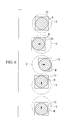
- FIG. 2
- shows a scanner of the microscope apparatus in
FIG. 1 and is a perspective view showing an example in which a position optically conjugate with a pupil position of an objective optical system is disposed at a higher-speed mirror. - FIG. 3
- is a diagram for describing the movement of a modulation region of a spatial light modulator of the microscope apparatus in
FIG. 1 , in the case ofFIG. 2 . - FIG. 4
- is a modification of
FIG. 2 , showing the scanner of the microscope apparatus inFIG. 1 , and is a perspective view showing an example in which a position optically conjugate with a pupil position of an objective optical system is located between the higher-speed mirror and a lower-speed mirror. - FIG. 5
- is a diagram for describing the movement of the modulation region of the spatial light modulator of the microscope apparatus in
FIG. 1 , in the case ofFIG. 4 . - FIG. 6
- is a modification of
FIG. 5 and is a diagram for describing the movement of the modulation region in the case where the spatial light modulator itself is moved. - A microscope apparatus 1 according to an embodiment of the present invention will be described below with reference to the drawings.
- As shown in
FIG. 1 , the microscope apparatus 1 according to this embodiment includes alight source 2 that generates a laser beam (illuminating light), a collimator lens 3 that converts the wavefront of the laser beam generated by thelight source 2 into a substantially plane wave, awavefront modulating unit 4 that modulates the wavefront of the laser beam converted into a substantially plane wave, a first relay optical system 5 that relays the laser beam whose wavefront is modulated by thewavefront modulating unit 4, a scanner 6 that two-dimensionally scans the laser beam relayed by the first relay optical system 5, a second relay optical system (relay optical system) 7 that relays the laser beam scanned by the scanner 6, an objectiveoptical system 8 that focuses the laser beam relayed by the second relay optical system 7, acontrol unit 9 that controls the scanner 6 and thewavefront modulating unit 4, and aphotodetector 10 that detects fluorescence from a specimen A collected by the objectiveoptical system 8. In the figure, thereference sign 11 denotes a stage that carries the specimen A placed on a slide glass. - The wavefront modulating
unit 4 includes a prism 12 that reflects a laser beam converted into a substantially plane wave by the collimator lens 3, and a reflectivespatial light modulator 13 that reflects the laser beam reflected by the prism 12. At this time, the reflectivespatial light modulator 13 modulates the wavefront of the laser beam such that it conforms to the surface shape thereof and returns the laser beam to the prism 12. - The optical path of the laser beam reflected by the prism 12 is folded back by the
spatial light modulator 13 so as to return to the same prism 12 and is returned by the prism 12 to the optical path coaxial with the laser beam from thelight source 2. - The
spatial light modulator 13 is composed of segmented MEMS, which can arbitrarily change the surface shape thereof according to a shape instruction signal from thecontrol unit 9. Thespatial light modulator 13 and the entrance pupil position of the objectiveoptical system 8 are located to have an optically conjugate positional relationship. - As shown by a chain line in
FIG. 3 , the laser beam made incident on thespatial light modulator 13 by the collimator lens 3 illuminates a region C (hereinafter referred to as an "illuminated region") that includes and is larger than a region B in which the wavefront is actually modulated (hereinafter referred to as a "modulation region"). - As shown in
FIG. 2 , the scanner 6 includes twomirrors FIG. 1 . - One
mirror 6a is designed to pivot at a sufficiently higher pivot speed than theother mirror 6b. The high-speed-side mirror 6a is used to scan the laser beam across the specimen A, and the low-speed-side mirror 6b is used to advance the scanning position of the laser beam on the specimen A. In the figure, thereference signs mirrors reference sign 14 denotes a mirror. - As shown in
FIG. 2 , the high-speed-side mirror 6a is disposed at a position optically conjugate with an entrance pupil position of the objectiveoptical system 8. The hatching inFIG. 2 shows that the higher-speed mirror 6a is disposed at a position optically conjugate with the entrance pupil position of the objectiveoptical system 8. - The first relay optical system 5 and the second relay optical system 7 are each composed of a plurality of lenses. The first relay optical system 5 is configured to relay an image formed on the surface of the spatial
light modulator 13 to the surface of the higher-speed mirror 6a. The second relay optical system 7 is configured to relay the image formed on the surface of the high-speed-side mirror 6a to the entrance pupil position of the objectiveoptical system 8. - In
FIG. 1 , thereference sign 15 denotes a dichroic mirror that reflects the laser beam while allowing the fluorescence to pass therethrough, and thereference sign 16 denotes a condenser lens. The fluorescence having passed through thedichroic mirror 15 is focused by thecondenser lens 16 and is detected by thephotodetector 10. By storing the intensity of the fluorescence detected by thephotodetector 10 in association with the information about the position of the scanner 6 scanning the laser beam during detection, a two-dimensional fluorescence image can be obtained. - The
control unit 9 outputs a shape instruction signal to the spatiallight modulator 13 so that the surface of the modulation region B of the spatiallight modulator 13 forms a preset shape. The surface shape of the modulation region B of the spatiallight modulator 13 is such that it can modulate the wavefront of the plane wave incident on the modulation region B and can focus it on one point at a focal position of the objectiveoptical system 8. This surface shape can be calculated or measured in advance, taking into consideration various aberrations of the optical systems, the refractive index distribution of the specimen A, and the like. - Furthermore, the
control unit 9 outputs angle instruction signals for instructing the pivot angles to themotors mirrors control unit 9 outputs a movement instruction signal for moving the modulation region B, in which the above-described surface shape is formed, within the illuminated region C, which is a region of the spatiallight modulator 13 over which the laser beam is illuminated, as shown by an arrow D inFIG. 3 . - More specifically, the wavefront modulation region B of the spatial
light modulator 13 is moved in response to pivoting of themirror 6b in such a manner that the image of the laser beam is moved, assuming that the lower-speed mirror 6b is fixed, in the direction opposite to the moving direction of the image of the laser beam at the entrance pupil position of the objectiveoptical system 8 assuming that the low-speed-side mirror 6b is pivoted while the modulation region B of the spatiallight modulator 13 is fixed. - The operation of the thus-configured microscope apparatus 1 according to this embodiment will be described below.
- In order to observe the fluorescence from the specimen A using the microscope apparatus 1 according to this embodiment, in a state in which the
control unit 9 outputs a shape instruction signal for instructing the surface shape in the modulation region B to the spatiallight modulator 13, a laser beam generated by thelight source 2 is converted into a substantially plane wave by the collimator lens 3 and is made incident on thewavefront modulating unit 4. - The laser beam incident on the
wavefront modulating unit 4 is reflected by the prism 12 and is incident on the spatiallight modulator 13. In the spatiallight modulator 13, the laser beam illuminates the illuminated region C that includes and is larger than the modulation region B, and only the wavefront of a portion of the laser beam incident on the modulation region B is modulated and reflected, is then reflected by the prism 12, and is incident on the first relay optical system 5. - The first relay optical system 5 relays an image in the modulation region B of the spatial
light modulator 13 to the surface of the high-speed-side mirror 6a of the scanner 6 disposed at a position optically conjugate therewith. In the scanner 6, the reflected laser beam is pivoted in the scanning direction by pivoting the higher-speed mirror 6a, and the reflected laser beam is pivoted in the advancing direction by pivoting the lower-speed mirror 6b. Thus, the laser beam is two-dimensionally scanned. - The laser beam scanned by the scanner 6 is incident on the second relay optical system 7.
- The second relay optical system 7 relays an image of the laser beam formed on the surface of the higher-
speed mirror 6a to the entrance pupil position of the objectiveoptical system 8 disposed at a position optically conjugate therewith. - In this manner, the image in the modulation region B of the spatial
light modulator 13 is relayed to the entrance pupil position of the objectiveoptical system 8. - In this case, if the scanner 6 is activated while the modulation region B of the spatial
light modulator 13 is fixed, pivoting of the lower-speed mirror 6b causes the image of the laser beam relayed to the entrance pupil position of the objectiveoptical system 8 to move linearly in the direction intersecting the optical axis. This direction of movement is assumed to be direction P, and the amount of movement is assumed to be ΔP. If, conversely, the modulation region B of the spatiallight modulator 13 is moved as shown by the arrow D within the illuminated region C while the lower-speed mirror 6b of the scanner 6 is stopped, the image of the laser beam relayed to the entrance pupil position of the objectiveoptical system 8 moves linearly in the direction intersecting the optical axis. This direction of movement is assumed to be direction Q, and the amount of movement is assumed to be ΔQ. - In this embodiment, because the
control unit 9 moves the modulation region B of the spatiallight modulator 13 such that the direction P and the direction Q are opposite to each other and such that ΔP = ΔQ, the image of the laser beam relayed to the entrance pupil position of the objectiveoptical system 8 can be maintained stationary, regardless of pivoting of the lower-speed mirror 6b. Because the laser beam incident on the entrance pupil position does not move in the direction intersecting the optical axis, the laser beam can be made incident on the entire entrance pupil. Thus, illumination can be performed with the maximum brightness. - Furthermore, in this case, because the modulation region B of the spatial
light modulator 13 is moved in the direction intersecting the optical axis of the laser beam so that the image at the entrance pupil position of the objectiveoptical system 8 is not moved by pivoting themirrors light modulator 13 can be accurately relayed to the entrance pupil position of the objectiveoptical system 8, thereby preventing degradation in the light focusing ability. - This configuration provides an advantage in that, because aberrations of various optical systems and aberrations generated by the refractive index distribution etc., in the specimen A are compensated for, the laser beam can be precisely focused on one desired point in the specimen A by the objective
optical system 8. If the laser beam generated by thelight source 2 is an extremely short pulse laser beam, fluorescence can be generated by a multiphoton excitation effect only at the focal position of the objectiveoptical system 8. Thus, a sharp fluorescence image can be obtained. - Furthermore, in this embodiment, because the pivot axis of the higher-
speed mirror 6a constituting the scanner 6 is disposed at a position optically conjugate with the surface of the spatiallight modulator 13 and the entrance pupil position of the objectiveoptical system 8, moving the modulation region B in response to pivoting of the high-speed-side mirror 6a is unnecessary. Accordingly, it is sufficient to move the modulation region B of the spatiallight modulator 13 in response to pivoting of the lower-speed mirror 6b, whose speed is much lower than the higher-speed mirror 6a, and the responsiveness of which may be low. Therefore, displacement of the image of the laser beam incident on the entrance pupil position of the objectiveoptical system 8, due to pivoting of themirrors - Furthermore, because not the spatial
light modulator 13, but the modulation region on the spatiallight modulator 13 is moved, it can be moved at high speed without causing vibration. - Note that, although a position optically conjugate with the entrance pupil position of the objective
optical system 8 is disposed on the pivot axis S1 of the higher-speed mirror 6a of the scanner 6 in this embodiment, the configuration is not limited thereto. For example, as shown inFIG. 4 , the position optically conjugate with the entrance pupil position of the objectiveoptical system 8 may be disposed between the twomirrors - By doing so, pivoting of either of the two
mirrors optical system 8. In order to keep it stationary, as shown inFIG. 5 , the modulation region B has to be moved not only in the arrow D direction, but also in the arrow E direction perpendicular thereto. - Meanwhile, by locating the position optically conjugate with the entrance pupil position of the objective
optical system 8 between the twomirrors optical system 8 in one direction due to pivoting of themirrors light modulator 13 and improving the illumination efficiency. For example, when the position optically conjugate with the entrance pupil position of the objectiveoptical system 8 is located precisely in the middle between the twomirrors optical system 8 in one direction is halved, compared with the case where it is located at one of the twomirrors - Furthermore, although the modulation region B is moved in the spatial
light modulator 13 in this embodiment, the spatiallight modulator 13 itself may be moved in the direction intersecting the optical axis relative to the illumination region C instead, as shown inFIG. 6 . This enables the modulation region B to be provided over substantially the entire spatiallight modulator 13, and it is possible to perform more detailed wavefront modulation utilizing the full spatial resolution of the spatiallight modulator 13. - Furthermore, although an example of the spatial
light modulator 13 according to this embodiment was a segmented MEMS mirror that changes the surface shape thereof, any another spatiallight modulator 13, for example, a liquid crystal device or a deformable mirror, may be used instead.
Claims (7)
- A microscope apparatus comprising:a spatial light modulator that modulates the wavefront of illuminating light from a light source;a scanner that has two mirrors independently pivoted about two non-parallel axes, and that two-dimensionally scans the illuminating light whose wavefront has been modulated by the spatial light modulator;a relay optical system that guides the illuminating light, whose traveling direction has been changed by the scanner, to an objective optical system; anda modulation-region adjusting unit that moves a wavefront modulation region of the spatial light modulator, in which an image is formed, in response to pivoting of the mirrors,wherein the modulation-region adjusting unit moves the modulation region such that an image at the pupil position of the objective optical system assuming that the mirrors are stationary is moved in the direction opposite to the direction of movement of the image relayed to the pupil position of the objective optical system assuming that the mirrors are pivoted while the image on the spatial light modulator is fixed.
- The microscope apparatus according to Claim 1, wherein the modulation-region adjusting unit moves the modulation region in the spatial light modulator.
- The microscope apparatus according to Claim 1, wherein the modulation-region adjusting unit moves the spatial light modulator.
- The microscope apparatus according to Claim 1, wherein the pivot axis of one mirror is disposed in a plane perpendicular to the pivot axis of the other mirror of the scanner, and the pupil position of the objective optical system and the position of one of the mirrors on the pivot axis have an optically conjugate relationship.
- The microscope apparatus according to Claim 4, wherein the pupil position of the objective optical system and the position, on the pivot axis, of the mirror that is pivoted at a higher speed in the two mirrors have an optically conjugate relationship.
- The microscope apparatus according to Claim 1, wherein the pupil position of the objective optical system and a position between the two mirrors have an optically conjugate relationship.
- The microscope apparatus according to any one of Claims 1 to 6, wherein the relay optical system is a second relay optical system, and the microscope apparatus includes a first relay optical system that relays an image on the spatial light modulator to a position having an optically conjugate relationship with the pupil position of the objective optical system of the second relay optical system.
Applications Claiming Priority (1)
| Application Number | Priority Date | Filing Date | Title |
|---|---|---|---|
| JP2010011046 | 2010-01-21 |
Publications (2)
| Publication Number | Publication Date |
|---|---|
| EP2360505A1 true EP2360505A1 (en) | 2011-08-24 |
| EP2360505B1 EP2360505B1 (en) | 2017-03-01 |
Family
ID=43828506
Family Applications (1)
| Application Number | Title | Priority Date | Filing Date |
|---|---|---|---|
| EP11000356.3A Not-in-force EP2360505B1 (en) | 2010-01-21 | 2011-01-18 | Microscope apparatus |
Country Status (3)
| Country | Link |
|---|---|
| US (1) | US8873123B2 (en) |
| EP (1) | EP2360505B1 (en) |
| JP (1) | JP5603786B2 (en) |
Cited By (1)
| Publication number | Priority date | Publication date | Assignee | Title |
|---|---|---|---|---|
| EP2827180A1 (en) * | 2013-06-24 | 2015-01-21 | Olympus Corporation | Scanning optical microscope |
Families Citing this family (5)
| Publication number | Priority date | Publication date | Assignee | Title |
|---|---|---|---|---|
| JP5991850B2 (en) * | 2012-05-11 | 2016-09-14 | オリンパス株式会社 | Microscope equipment |
| JP6385711B2 (en) * | 2014-04-30 | 2018-09-05 | オリンパス株式会社 | Microscope equipment |
| JP6353703B2 (en) * | 2014-05-26 | 2018-07-04 | オリンパス株式会社 | Microscope equipment |
| JP2022503883A (en) * | 2018-09-28 | 2022-01-12 | コーニング インコーポレイテッド | Rotary light source used to modify the board |
| DE102019208232A1 (en) * | 2019-06-05 | 2020-12-10 | Carl Zeiss Microscopy Gmbh | Optical arrangement and method for correcting centering errors and / or angle errors |
Citations (7)
| Publication number | Priority date | Publication date | Assignee | Title |
|---|---|---|---|---|
| US5760951A (en) * | 1992-09-01 | 1998-06-02 | Arthur Edward Dixon | Apparatus and method for scanning laser imaging of macroscopic samples |
| EP1372011A2 (en) * | 2002-06-15 | 2003-12-17 | CARL ZEISS JENA GmbH | Microscope, especially laser scanning microscope with adaptive optical device |
| US6771417B1 (en) * | 1997-08-01 | 2004-08-03 | Carl Zeiss Jena Gmbh | Applications of adaptive optics in microscopy |
| JP2005165212A (en) | 2003-12-05 | 2005-06-23 | Olympus Corp | Scanning confocal microscopic device |
| US20060007534A1 (en) * | 2000-12-26 | 2006-01-12 | Olympus Corporation | Scanning optical microscope |
| US20060152799A1 (en) * | 2005-01-11 | 2006-07-13 | Olympus Corporation | Optical microscope |
| GB2441162A (en) * | 2006-08-23 | 2008-02-27 | Shiv Kumar Sharma | Three-dimensional image recording and display apparatus with variable focal plane |
Family Cites Families (14)
| Publication number | Priority date | Publication date | Assignee | Title |
|---|---|---|---|---|
| JP2959830B2 (en) * | 1990-10-30 | 1999-10-06 | オリンパス光学工業株式会社 | Optical scanning device |
| DE10139920B4 (en) * | 2001-08-14 | 2008-07-31 | Leica Microsystems Cms Gmbh | Scanning microscope and method for scanning an object |
| JP4723842B2 (en) * | 2004-10-05 | 2011-07-13 | オリンパス株式会社 | Scanning optical microscope |
| EP1744194B1 (en) * | 2005-07-11 | 2017-05-10 | Olympus Corporation | Laser scanning microscope and image acquiring method of laser scanning microscope |
| DE102006028530A1 (en) * | 2005-11-11 | 2007-05-16 | Till I D Gmbh | Microscope having optional investigation of a sample has two light beams on different directions and a beam deflector operated by a drive to couple a beam to the objective |
| US7742213B2 (en) * | 2005-12-29 | 2010-06-22 | Rensselaer Polytechnic Institute | Adaptive-scanning optical microscope |
| JP2008203813A (en) * | 2007-01-24 | 2008-09-04 | Olympus Corp | Scanning microscope |
| DE102007009550B4 (en) * | 2007-02-27 | 2008-12-18 | Ludwig-Maximilian-Universität | Method and microscope device for observing a moving sample |
| JP4928351B2 (en) * | 2007-05-25 | 2012-05-09 | オリンパス株式会社 | microscope |
| US7729049B2 (en) * | 2007-05-26 | 2010-06-01 | Zeta Instruments, Inc. | 3-d optical microscope |
| JP2009058776A (en) * | 2007-08-31 | 2009-03-19 | Olympus Corp | Optical system equipped with focusing optical system, and laser microscope apparatus using same |
| US8280131B2 (en) * | 2007-11-26 | 2012-10-02 | Carl Zeiss Micro Imaging Gmbh | Method and configuration for optically detecting an illuminated specimen |
| US20090174935A1 (en) * | 2008-01-09 | 2009-07-09 | Szulczewski Michael J | Scanning microscope having complementary, serial scanners |
| JP5554965B2 (en) * | 2009-11-06 | 2014-07-23 | オリンパス株式会社 | Laser microscope using phase modulation spatial light modulator |
-
2011
- 2011-01-18 EP EP11000356.3A patent/EP2360505B1/en not_active Not-in-force
- 2011-01-18 JP JP2011008248A patent/JP5603786B2/en not_active Expired - Fee Related
- 2011-01-19 US US12/930,963 patent/US8873123B2/en not_active Expired - Fee Related
Patent Citations (7)
| Publication number | Priority date | Publication date | Assignee | Title |
|---|---|---|---|---|
| US5760951A (en) * | 1992-09-01 | 1998-06-02 | Arthur Edward Dixon | Apparatus and method for scanning laser imaging of macroscopic samples |
| US6771417B1 (en) * | 1997-08-01 | 2004-08-03 | Carl Zeiss Jena Gmbh | Applications of adaptive optics in microscopy |
| US20060007534A1 (en) * | 2000-12-26 | 2006-01-12 | Olympus Corporation | Scanning optical microscope |
| EP1372011A2 (en) * | 2002-06-15 | 2003-12-17 | CARL ZEISS JENA GmbH | Microscope, especially laser scanning microscope with adaptive optical device |
| JP2005165212A (en) | 2003-12-05 | 2005-06-23 | Olympus Corp | Scanning confocal microscopic device |
| US20060152799A1 (en) * | 2005-01-11 | 2006-07-13 | Olympus Corporation | Optical microscope |
| GB2441162A (en) * | 2006-08-23 | 2008-02-27 | Shiv Kumar Sharma | Three-dimensional image recording and display apparatus with variable focal plane |
Cited By (2)
| Publication number | Priority date | Publication date | Assignee | Title |
|---|---|---|---|---|
| EP2827180A1 (en) * | 2013-06-24 | 2015-01-21 | Olympus Corporation | Scanning optical microscope |
| US9261689B2 (en) | 2013-06-24 | 2016-02-16 | Olympus Corporation | Scanning optical microscope |
Also Published As
| Publication number | Publication date |
|---|---|
| JP5603786B2 (en) | 2014-10-08 |
| US8873123B2 (en) | 2014-10-28 |
| EP2360505B1 (en) | 2017-03-01 |
| JP2011170338A (en) | 2011-09-01 |
| US20110255157A1 (en) | 2011-10-20 |
Similar Documents
| Publication | Publication Date | Title |
|---|---|---|
| US8773760B2 (en) | Multi-point scan architecture | |
| US10108008B2 (en) | Image-forming optical system, illumination apparatus, and observation apparatus | |
| US8873123B2 (en) | Microscope apparatus having a modulation-region adjusting unit that moves a wavefront modulation region in response to pivoting of mirrors | |
| EP2093600A1 (en) | Laser scan confocal microscope | |
| US20160124201A1 (en) | Light sheet illumination microscope and light sheet illumination method | |
| US10983327B2 (en) | Light sheet microscope | |
| US20170219809A1 (en) | Light-Scanning Microscope with Simplified Optical System, More Particularly with Variable Pupil Position | |
| US11428916B2 (en) | Light sheet microscope | |
| US10437050B2 (en) | Phase-modulation-element adjustment system and method for decreasing wavefront aberration | |
| US20170192217A1 (en) | Optical-axis-direction scanning microscope apparatus | |
| EP2498116B1 (en) | Microscope apparatus | |
| US8908270B2 (en) | Microscope apparatus | |
| US9625693B2 (en) | Observation apparatus | |
| EP2827180B1 (en) | Scanning optical microscope | |
| US20120120469A1 (en) | Illumination optical system | |
| JP2012022282A (en) | Scanner, scanning type illumination device, and scanning type observation device | |
| JP6385711B2 (en) | Microscope equipment | |
| US10168283B2 (en) | Observation apparatus and method for sharpening final image | |
| JP2008026643A (en) | Laser scanning microscope | |
| JP2019045783A (en) | Light sheet microscope | |
| JP2012150238A (en) | Microscope device | |
| JP5591073B2 (en) | Microscope equipment | |
| JP2006106337A (en) | Scanning optical microscope |
Legal Events
| Date | Code | Title | Description |
|---|---|---|---|
| PUAI | Public reference made under article 153(3) epc to a published international application that has entered the european phase |
Free format text: ORIGINAL CODE: 0009012 |
|
| AK | Designated contracting states |
Kind code of ref document: A1 Designated state(s): AL AT BE BG CH CY CZ DE DK EE ES FI FR GB GR HR HU IE IS IT LI LT LU LV MC MK MT NL NO PL PT RO RS SE SI SK SM TR |
|
| AX | Request for extension of the european patent |
Extension state: BA ME |
|
| 17P | Request for examination filed |
Effective date: 20120224 |
|
| 17Q | First examination report despatched |
Effective date: 20160105 |
|
| RAP1 | Party data changed (applicant data changed or rights of an application transferred) |
Owner name: OLYMPUS CORPORATION |
|
| RAP1 | Party data changed (applicant data changed or rights of an application transferred) |
Owner name: OLYMPUS CORPORATION |
|
| GRAP | Despatch of communication of intention to grant a patent |
Free format text: ORIGINAL CODE: EPIDOSNIGR1 |
|
| RIN1 | Information on inventor provided before grant (corrected) |
Inventor name: MURAYAMA, YOSHIAKI |
|
| RIC1 | Information provided on ipc code assigned before grant |
Ipc: G02B 26/10 20060101ALI20160930BHEP Ipc: G02B 21/00 20060101AFI20160930BHEP |
|
| INTG | Intention to grant announced |
Effective date: 20161024 |
|
| RIN1 | Information on inventor provided before grant (corrected) |
Inventor name: MURAYAMA, YOSHIAKI |
|
| STAA | Information on the status of an ep patent application or granted ep patent |
Free format text: STATUS: GRANT OF PATENT IS INTENDED |
|
| GRAS | Grant fee paid |
Free format text: ORIGINAL CODE: EPIDOSNIGR3 |
|
| GRAA | (expected) grant |
Free format text: ORIGINAL CODE: 0009210 |
|
| STAA | Information on the status of an ep patent application or granted ep patent |
Free format text: STATUS: THE PATENT HAS BEEN GRANTED |
|
| AK | Designated contracting states |
Kind code of ref document: B1 Designated state(s): AL AT BE BG CH CY CZ DE DK EE ES FI FR GB GR HR HU IE IS IT LI LT LU LV MC MK MT NL NO PL PT RO RS SE SI SK SM TR |
|
| REG | Reference to a national code |
Ref country code: GB Ref legal event code: FG4D |
|
| REG | Reference to a national code |
Ref country code: CH Ref legal event code: EP Ref country code: AT Ref legal event code: REF Ref document number: 872013 Country of ref document: AT Kind code of ref document: T Effective date: 20170315 |
|
| REG | Reference to a national code |
Ref country code: IE Ref legal event code: FG4D |
|
| REG | Reference to a national code |
Ref country code: DE Ref legal event code: R096 Ref document number: 602011035341 Country of ref document: DE |
|
| REG | Reference to a national code |
Ref country code: NL Ref legal event code: MP Effective date: 20170301 |
|
| REG | Reference to a national code |
Ref country code: LT Ref legal event code: MG4D |
|
| REG | Reference to a national code |
Ref country code: AT Ref legal event code: MK05 Ref document number: 872013 Country of ref document: AT Kind code of ref document: T Effective date: 20170301 |
|
| PG25 | Lapsed in a contracting state [announced via postgrant information from national office to epo] |
Ref country code: NO Free format text: LAPSE BECAUSE OF FAILURE TO SUBMIT A TRANSLATION OF THE DESCRIPTION OR TO PAY THE FEE WITHIN THE PRESCRIBED TIME-LIMIT Effective date: 20170601 Ref country code: FI Free format text: LAPSE BECAUSE OF FAILURE TO SUBMIT A TRANSLATION OF THE DESCRIPTION OR TO PAY THE FEE WITHIN THE PRESCRIBED TIME-LIMIT Effective date: 20170301 Ref country code: HR Free format text: LAPSE BECAUSE OF FAILURE TO SUBMIT A TRANSLATION OF THE DESCRIPTION OR TO PAY THE FEE WITHIN THE PRESCRIBED TIME-LIMIT Effective date: 20170301 Ref country code: GR Free format text: LAPSE BECAUSE OF FAILURE TO SUBMIT A TRANSLATION OF THE DESCRIPTION OR TO PAY THE FEE WITHIN THE PRESCRIBED TIME-LIMIT Effective date: 20170602 Ref country code: LT Free format text: LAPSE BECAUSE OF FAILURE TO SUBMIT A TRANSLATION OF THE DESCRIPTION OR TO PAY THE FEE WITHIN THE PRESCRIBED TIME-LIMIT Effective date: 20170301 |
|
| PG25 | Lapsed in a contracting state [announced via postgrant information from national office to epo] |
Ref country code: ES Free format text: LAPSE BECAUSE OF FAILURE TO SUBMIT A TRANSLATION OF THE DESCRIPTION OR TO PAY THE FEE WITHIN THE PRESCRIBED TIME-LIMIT Effective date: 20170301 Ref country code: SE Free format text: LAPSE BECAUSE OF FAILURE TO SUBMIT A TRANSLATION OF THE DESCRIPTION OR TO PAY THE FEE WITHIN THE PRESCRIBED TIME-LIMIT Effective date: 20170301 Ref country code: AT Free format text: LAPSE BECAUSE OF FAILURE TO SUBMIT A TRANSLATION OF THE DESCRIPTION OR TO PAY THE FEE WITHIN THE PRESCRIBED TIME-LIMIT Effective date: 20170301 Ref country code: LV Free format text: LAPSE BECAUSE OF FAILURE TO SUBMIT A TRANSLATION OF THE DESCRIPTION OR TO PAY THE FEE WITHIN THE PRESCRIBED TIME-LIMIT Effective date: 20170301 Ref country code: BG Free format text: LAPSE BECAUSE OF FAILURE TO SUBMIT A TRANSLATION OF THE DESCRIPTION OR TO PAY THE FEE WITHIN THE PRESCRIBED TIME-LIMIT Effective date: 20170601 Ref country code: RS Free format text: LAPSE BECAUSE OF FAILURE TO SUBMIT A TRANSLATION OF THE DESCRIPTION OR TO PAY THE FEE WITHIN THE PRESCRIBED TIME-LIMIT Effective date: 20170301 |
|
| PG25 | Lapsed in a contracting state [announced via postgrant information from national office to epo] |
Ref country code: NL Free format text: LAPSE BECAUSE OF FAILURE TO SUBMIT A TRANSLATION OF THE DESCRIPTION OR TO PAY THE FEE WITHIN THE PRESCRIBED TIME-LIMIT Effective date: 20170301 |
|
| PG25 | Lapsed in a contracting state [announced via postgrant information from national office to epo] |
Ref country code: CZ Free format text: LAPSE BECAUSE OF FAILURE TO SUBMIT A TRANSLATION OF THE DESCRIPTION OR TO PAY THE FEE WITHIN THE PRESCRIBED TIME-LIMIT Effective date: 20170301 Ref country code: SK Free format text: LAPSE BECAUSE OF FAILURE TO SUBMIT A TRANSLATION OF THE DESCRIPTION OR TO PAY THE FEE WITHIN THE PRESCRIBED TIME-LIMIT Effective date: 20170301 Ref country code: RO Free format text: LAPSE BECAUSE OF FAILURE TO SUBMIT A TRANSLATION OF THE DESCRIPTION OR TO PAY THE FEE WITHIN THE PRESCRIBED TIME-LIMIT Effective date: 20170301 Ref country code: EE Free format text: LAPSE BECAUSE OF FAILURE TO SUBMIT A TRANSLATION OF THE DESCRIPTION OR TO PAY THE FEE WITHIN THE PRESCRIBED TIME-LIMIT Effective date: 20170301 |
|
| PG25 | Lapsed in a contracting state [announced via postgrant information from national office to epo] |
Ref country code: PT Free format text: LAPSE BECAUSE OF FAILURE TO SUBMIT A TRANSLATION OF THE DESCRIPTION OR TO PAY THE FEE WITHIN THE PRESCRIBED TIME-LIMIT Effective date: 20170703 Ref country code: IS Free format text: LAPSE BECAUSE OF FAILURE TO SUBMIT A TRANSLATION OF THE DESCRIPTION OR TO PAY THE FEE WITHIN THE PRESCRIBED TIME-LIMIT Effective date: 20170701 Ref country code: SM Free format text: LAPSE BECAUSE OF FAILURE TO SUBMIT A TRANSLATION OF THE DESCRIPTION OR TO PAY THE FEE WITHIN THE PRESCRIBED TIME-LIMIT Effective date: 20170301 Ref country code: PL Free format text: LAPSE BECAUSE OF FAILURE TO SUBMIT A TRANSLATION OF THE DESCRIPTION OR TO PAY THE FEE WITHIN THE PRESCRIBED TIME-LIMIT Effective date: 20170301 |
|
| REG | Reference to a national code |
Ref country code: DE Ref legal event code: R097 Ref document number: 602011035341 Country of ref document: DE |
|
| PLBE | No opposition filed within time limit |
Free format text: ORIGINAL CODE: 0009261 |
|
| STAA | Information on the status of an ep patent application or granted ep patent |
Free format text: STATUS: NO OPPOSITION FILED WITHIN TIME LIMIT |
|
| PG25 | Lapsed in a contracting state [announced via postgrant information from national office to epo] |
Ref country code: DK Free format text: LAPSE BECAUSE OF FAILURE TO SUBMIT A TRANSLATION OF THE DESCRIPTION OR TO PAY THE FEE WITHIN THE PRESCRIBED TIME-LIMIT Effective date: 20170301 |
|
| 26N | No opposition filed |
Effective date: 20171204 |
|
| PG25 | Lapsed in a contracting state [announced via postgrant information from national office to epo] |
Ref country code: IT Free format text: LAPSE BECAUSE OF FAILURE TO SUBMIT A TRANSLATION OF THE DESCRIPTION OR TO PAY THE FEE WITHIN THE PRESCRIBED TIME-LIMIT Effective date: 20170301 Ref country code: SI Free format text: LAPSE BECAUSE OF FAILURE TO SUBMIT A TRANSLATION OF THE DESCRIPTION OR TO PAY THE FEE WITHIN THE PRESCRIBED TIME-LIMIT Effective date: 20170301 |
|
| REG | Reference to a national code |
Ref country code: CH Ref legal event code: PL |
|
| GBPC | Gb: european patent ceased through non-payment of renewal fee |
Effective date: 20180118 |
|
| PG25 | Lapsed in a contracting state [announced via postgrant information from national office to epo] |
Ref country code: FR Free format text: LAPSE BECAUSE OF NON-PAYMENT OF DUE FEES Effective date: 20180131 Ref country code: LU Free format text: LAPSE BECAUSE OF NON-PAYMENT OF DUE FEES Effective date: 20180118 |
|
| REG | Reference to a national code |
Ref country code: IE Ref legal event code: MM4A |
|
| REG | Reference to a national code |
Ref country code: FR Ref legal event code: ST Effective date: 20180928 |
|
| REG | Reference to a national code |
Ref country code: BE Ref legal event code: MM Effective date: 20180131 |
|
| PG25 | Lapsed in a contracting state [announced via postgrant information from national office to epo] |
Ref country code: LI Free format text: LAPSE BECAUSE OF NON-PAYMENT OF DUE FEES Effective date: 20180131 Ref country code: CH Free format text: LAPSE BECAUSE OF NON-PAYMENT OF DUE FEES Effective date: 20180131 Ref country code: BE Free format text: LAPSE BECAUSE OF NON-PAYMENT OF DUE FEES Effective date: 20180131 Ref country code: GB Free format text: LAPSE BECAUSE OF NON-PAYMENT OF DUE FEES Effective date: 20180118 |
|
| PG25 | Lapsed in a contracting state [announced via postgrant information from national office to epo] |
Ref country code: IE Free format text: LAPSE BECAUSE OF NON-PAYMENT OF DUE FEES Effective date: 20180118 |
|
| PGFP | Annual fee paid to national office [announced via postgrant information from national office to epo] |
Ref country code: DE Payment date: 20190123 Year of fee payment: 9 |
|
| PG25 | Lapsed in a contracting state [announced via postgrant information from national office to epo] |
Ref country code: MC Free format text: LAPSE BECAUSE OF FAILURE TO SUBMIT A TRANSLATION OF THE DESCRIPTION OR TO PAY THE FEE WITHIN THE PRESCRIBED TIME-LIMIT Effective date: 20170301 |
|
| PG25 | Lapsed in a contracting state [announced via postgrant information from national office to epo] |
Ref country code: MT Free format text: LAPSE BECAUSE OF NON-PAYMENT OF DUE FEES Effective date: 20180118 |
|
| PG25 | Lapsed in a contracting state [announced via postgrant information from national office to epo] |
Ref country code: TR Free format text: LAPSE BECAUSE OF FAILURE TO SUBMIT A TRANSLATION OF THE DESCRIPTION OR TO PAY THE FEE WITHIN THE PRESCRIBED TIME-LIMIT Effective date: 20170301 |
|
| PG25 | Lapsed in a contracting state [announced via postgrant information from national office to epo] |
Ref country code: HU Free format text: LAPSE BECAUSE OF FAILURE TO SUBMIT A TRANSLATION OF THE DESCRIPTION OR TO PAY THE FEE WITHIN THE PRESCRIBED TIME-LIMIT; INVALID AB INITIO Effective date: 20110118 |
|
| PG25 | Lapsed in a contracting state [announced via postgrant information from national office to epo] |
Ref country code: MK Free format text: LAPSE BECAUSE OF NON-PAYMENT OF DUE FEES Effective date: 20170301 Ref country code: CY Free format text: LAPSE BECAUSE OF FAILURE TO SUBMIT A TRANSLATION OF THE DESCRIPTION OR TO PAY THE FEE WITHIN THE PRESCRIBED TIME-LIMIT Effective date: 20170301 |
|
| PG25 | Lapsed in a contracting state [announced via postgrant information from national office to epo] |
Ref country code: AL Free format text: LAPSE BECAUSE OF FAILURE TO SUBMIT A TRANSLATION OF THE DESCRIPTION OR TO PAY THE FEE WITHIN THE PRESCRIBED TIME-LIMIT Effective date: 20170301 |
|
| REG | Reference to a national code |
Ref country code: DE Ref legal event code: R119 Ref document number: 602011035341 Country of ref document: DE |
|
| PG25 | Lapsed in a contracting state [announced via postgrant information from national office to epo] |
Ref country code: DE Free format text: LAPSE BECAUSE OF NON-PAYMENT OF DUE FEES Effective date: 20200801 |