EP2353645A1 - Electrosurgical devices with choke shorted to biological tissue - Google Patents
Electrosurgical devices with choke shorted to biological tissue Download PDFInfo
- Publication number
- EP2353645A1 EP2353645A1 EP11000913A EP11000913A EP2353645A1 EP 2353645 A1 EP2353645 A1 EP 2353645A1 EP 11000913 A EP11000913 A EP 11000913A EP 11000913 A EP11000913 A EP 11000913A EP 2353645 A1 EP2353645 A1 EP 2353645A1
- Authority
- EP
- European Patent Office
- Prior art keywords
- electrically
- dielectric material
- conductive member
- outer conductor
- tissue
- Prior art date
- Legal status (The legal status is an assumption and is not a legal conclusion. Google has not performed a legal analysis and makes no representation as to the accuracy of the status listed.)
- Granted
Links
- 239000004020 conductor Substances 0.000 claims abstract description 87
- 239000003989 dielectric material Substances 0.000 claims abstract description 57
- 238000002679 ablation Methods 0.000 claims description 43
- 239000000523 sample Substances 0.000 claims description 32
- 210000001519 tissue Anatomy 0.000 description 61
- 238000000034 method Methods 0.000 description 33
- 230000005540 biological transmission Effects 0.000 description 12
- 230000005670 electromagnetic radiation Effects 0.000 description 12
- 230000005855 radiation Effects 0.000 description 10
- 206010028980 Neoplasm Diseases 0.000 description 9
- 239000002826 coolant Substances 0.000 description 9
- -1 e.g. Substances 0.000 description 9
- 239000000463 material Substances 0.000 description 7
- 239000010935 stainless steel Substances 0.000 description 6
- 229910001220 stainless steel Inorganic materials 0.000 description 6
- 210000004027 cell Anatomy 0.000 description 5
- 230000000712 assembly Effects 0.000 description 4
- 238000000429 assembly Methods 0.000 description 4
- 238000002591 computed tomography Methods 0.000 description 4
- 230000005404 monopole Effects 0.000 description 4
- 238000000465 moulding Methods 0.000 description 4
- 238000004088 simulation Methods 0.000 description 4
- RYGMFSIKBFXOCR-UHFFFAOYSA-N Copper Chemical compound [Cu] RYGMFSIKBFXOCR-UHFFFAOYSA-N 0.000 description 3
- 239000000919 ceramic Substances 0.000 description 3
- 229910052802 copper Inorganic materials 0.000 description 3
- 239000010949 copper Substances 0.000 description 3
- 230000006378 damage Effects 0.000 description 3
- 239000012530 fluid Substances 0.000 description 3
- PCHJSUWPFVWCPO-UHFFFAOYSA-N gold Chemical compound [Au] PCHJSUWPFVWCPO-UHFFFAOYSA-N 0.000 description 3
- 229910052737 gold Inorganic materials 0.000 description 3
- 239000010931 gold Substances 0.000 description 3
- 229920002614 Polyether block amide Polymers 0.000 description 2
- 230000000903 blocking effect Effects 0.000 description 2
- 201000011510 cancer Diseases 0.000 description 2
- 239000011248 coating agent Substances 0.000 description 2
- 238000000576 coating method Methods 0.000 description 2
- 230000001419 dependent effect Effects 0.000 description 2
- 201000010099 disease Diseases 0.000 description 2
- 208000037265 diseases, disorders, signs and symptoms Diseases 0.000 description 2
- 238000010438 heat treatment Methods 0.000 description 2
- 229920001721 polyimide Polymers 0.000 description 2
- 229920001343 polytetrafluoroethylene Polymers 0.000 description 2
- 239000004810 polytetrafluoroethylene Substances 0.000 description 2
- 238000002271 resection Methods 0.000 description 2
- 229910052709 silver Inorganic materials 0.000 description 2
- 239000004332 silver Substances 0.000 description 2
- 238000001356 surgical procedure Methods 0.000 description 2
- 210000004881 tumor cell Anatomy 0.000 description 2
- 238000002604 ultrasonography Methods 0.000 description 2
- 230000000007 visual effect Effects 0.000 description 2
- XLYOFNOQVPJJNP-UHFFFAOYSA-N water Substances O XLYOFNOQVPJJNP-UHFFFAOYSA-N 0.000 description 2
- 241000272201 Columbiformes Species 0.000 description 1
- 239000004697 Polyetherimide Substances 0.000 description 1
- 239000004698 Polyethylene Substances 0.000 description 1
- 239000004642 Polyimide Substances 0.000 description 1
- BQCADISMDOOEFD-UHFFFAOYSA-N Silver Chemical compound [Ag] BQCADISMDOOEFD-UHFFFAOYSA-N 0.000 description 1
- FAPWRFPIFSIZLT-UHFFFAOYSA-M Sodium chloride Chemical compound [Na+].[Cl-] FAPWRFPIFSIZLT-UHFFFAOYSA-M 0.000 description 1
- 229920006362 Teflon® Polymers 0.000 description 1
- 229920004738 ULTEM® Polymers 0.000 description 1
- 239000000853 adhesive Substances 0.000 description 1
- 230000001070 adhesive effect Effects 0.000 description 1
- 210000000481 breast Anatomy 0.000 description 1
- 229910010293 ceramic material Inorganic materials 0.000 description 1
- 230000001112 coagulating effect Effects 0.000 description 1
- 230000015271 coagulation Effects 0.000 description 1
- 238000005345 coagulation Methods 0.000 description 1
- 150000001875 compounds Chemical class 0.000 description 1
- 238000010276 construction Methods 0.000 description 1
- 238000001816 cooling Methods 0.000 description 1
- 230000003247 decreasing effect Effects 0.000 description 1
- 230000008021 deposition Effects 0.000 description 1
- 238000010586 diagram Methods 0.000 description 1
- 238000007598 dipping method Methods 0.000 description 1
- 239000011521 glass Substances 0.000 description 1
- 210000005003 heart tissue Anatomy 0.000 description 1
- 238000009217 hyperthermia therapy Methods 0.000 description 1
- 230000000266 injurious effect Effects 0.000 description 1
- 238000003780 insertion Methods 0.000 description 1
- 230000037431 insertion Effects 0.000 description 1
- 239000012212 insulator Substances 0.000 description 1
- 230000002427 irreversible effect Effects 0.000 description 1
- 210000005228 liver tissue Anatomy 0.000 description 1
- 230000003211 malignant effect Effects 0.000 description 1
- 230000008384 membrane barrier Effects 0.000 description 1
- 239000002184 metal Substances 0.000 description 1
- 229910052751 metal Inorganic materials 0.000 description 1
- 229910001092 metal group alloy Inorganic materials 0.000 description 1
- 229910044991 metal oxide Inorganic materials 0.000 description 1
- 150000004706 metal oxides Chemical class 0.000 description 1
- 150000002739 metals Chemical class 0.000 description 1
- 239000010445 mica Substances 0.000 description 1
- 229910052618 mica group Inorganic materials 0.000 description 1
- 238000012986 modification Methods 0.000 description 1
- 230000004048 modification Effects 0.000 description 1
- 239000000615 nonconductor Substances 0.000 description 1
- 210000000056 organ Anatomy 0.000 description 1
- 239000004033 plastic Substances 0.000 description 1
- 229920003023 plastic Polymers 0.000 description 1
- 229920003223 poly(pyromellitimide-1,4-diphenyl ether) Polymers 0.000 description 1
- 229920001601 polyetherimide Polymers 0.000 description 1
- 229920000573 polyethylene Polymers 0.000 description 1
- 239000005020 polyethylene terephthalate Substances 0.000 description 1
- 229920000139 polyethylene terephthalate Polymers 0.000 description 1
- 239000000843 powder Substances 0.000 description 1
- 208000011571 secondary malignant neoplasm Diseases 0.000 description 1
- 239000011780 sodium chloride Substances 0.000 description 1
- 238000005507 spraying Methods 0.000 description 1
- 239000000758 substrate Substances 0.000 description 1
- 238000002560 therapeutic procedure Methods 0.000 description 1
- 229920002725 thermoplastic elastomer Polymers 0.000 description 1
- 230000008467 tissue growth Effects 0.000 description 1
- 210000003462 vein Anatomy 0.000 description 1
Images


Classifications
-
- A—HUMAN NECESSITIES
- A61—MEDICAL OR VETERINARY SCIENCE; HYGIENE
- A61B—DIAGNOSIS; SURGERY; IDENTIFICATION
- A61B18/00—Surgical instruments, devices or methods for transferring non-mechanical forms of energy to or from the body
- A61B18/18—Surgical instruments, devices or methods for transferring non-mechanical forms of energy to or from the body by applying electromagnetic radiation, e.g. microwaves
- A61B18/1815—Surgical instruments, devices or methods for transferring non-mechanical forms of energy to or from the body by applying electromagnetic radiation, e.g. microwaves using microwaves
- A61B2018/183—Surgical instruments, devices or methods for transferring non-mechanical forms of energy to or from the body by applying electromagnetic radiation, e.g. microwaves using microwaves characterised by the type of antenna
- A61B2018/1838—Dipole antennas
-
- A—HUMAN NECESSITIES
- A61—MEDICAL OR VETERINARY SCIENCE; HYGIENE
- A61B—DIAGNOSIS; SURGERY; IDENTIFICATION
- A61B18/00—Surgical instruments, devices or methods for transferring non-mechanical forms of energy to or from the body
- A61B18/18—Surgical instruments, devices or methods for transferring non-mechanical forms of energy to or from the body by applying electromagnetic radiation, e.g. microwaves
- A61B18/1815—Surgical instruments, devices or methods for transferring non-mechanical forms of energy to or from the body by applying electromagnetic radiation, e.g. microwaves using microwaves
- A61B2018/1869—Surgical instruments, devices or methods for transferring non-mechanical forms of energy to or from the body by applying electromagnetic radiation, e.g. microwaves using microwaves with an instrument interstitially inserted into the body, e.g. needles
-
- A—HUMAN NECESSITIES
- A61—MEDICAL OR VETERINARY SCIENCE; HYGIENE
- A61B—DIAGNOSIS; SURGERY; IDENTIFICATION
- A61B34/00—Computer-aided surgery; Manipulators or robots specially adapted for use in surgery
- A61B34/20—Surgical navigation systems; Devices for tracking or guiding surgical instruments, e.g. for frameless stereotaxis
Definitions
- the present disclosure relates to electrosurgical devices suitable for use in tissue ablation applications and, more particularly, to electrosurgical devices with a choke shorted to biological tissue and methods of directing electromagnetic radiation to tissue using the same.
- Electromagnetic radiation can be used to heat and destroy tumor cells. Treatment may involve inserting ablation probes into tissues where cancerous tumors have been identified. Once the probes are positioned, electromagnetic energy is passed through the probes into surrounding tissue.
- microwave apparatus for use in ablation procedures include a microwave generator that functions as an energy source, and a microwave surgical instrument (e.g., microwave ablation probe) having an antenna assembly for directing the energy to the target tissue.
- the microwave generator and surgical instrument are typically operatively coupled by a cable assembly having a plurality of conductors for transmitting microwave energy from the generator to the instrument, and for communicating control, feedback and identification signals between the instrument and the generator.
- monopole and dipole antenna assemblies microwave energy generally radiates perpendicularly away from the axis of the conductor.
- Monopole antenna assemblies typically include a single, elongated conductor.
- a typical dipole antenna assembly includes two elongated conductors that are linearly aligned and positioned end-to-end relative to one another with an electrical insulator placed therebetween.
- Helical antenna assemblies include helically-shaped conductor configurations of various and dimensions, e.g., diameter and length.
- the main modes of operation of a helical antenna assembly are normal mode (broadside), in which the field radiated by the helix is maximum in a perpendicular plane to the helix axis, and axial mode (end fire), in which maximum radiation is along the helix axis.
- a microwave transmission line typically includes a long, thin inner conductor that extends along the longitudinal axis of the transmission line and is surrounded by a dielectric material and is further surrounded by an outer conductor around the dielectric material such that the outer conductor also extends along the transmission line axis.
- a waveguiding structure such as a length of transmission line or coaxial cable, is provided with a plurality of openings through which energy "leaks” or radiates away from the guiding structure. This type of construction is typically referred to as a “leaky coaxial” or “leaky wave” antenna.
- the present disclosure relates to a device for directing energy to tissue including a feedline and a radiating portion electrically coupled to the feedline.
- the radiating portion includes a distal radiating section and a proximal radiating section.
- the feedline includes an inner conductor, an outer conductor and a first dielectric material disposed therebetween.
- the device also includes a choke disposed around at least a portion of the feedline.
- the choke includes a second dielectric material disposed around at least a portion of the outer conductor, wherein the second dielectric material includes one or more openings defined therein, and an electrically-conductive member disposed in the one opening(s) electrically coupled to the outer conductor, wherein the electrically-conductive member is configured to contact tissue.
- the present disclosure also relates to ablation probe for providing energy to tissue including an inner conductor, an outer conductor coaxially surrounding the inner conductor, the outer conductor having a proximal portion and a distal portion.
- a first dielectric material is disposed between the inner conductor and the outer conductor, and a second dielectric material disposed around at least a portion of the distal portion of the outer conductor.
- the ablation probe also includes a third dielectric material disposed around the proximal portion of the outer conductor, wherein the third dielectric material includes an opening defined therein.
- An electrically-conductive member is disposed in the opening electrically coupled to the proximal portion of the outer conductor, wherein the electrically-conductive member is configured to contact tissue.
- the present disclosure also relates to a method of directing energy to tissue that includes the initial step of positioning an antenna assembly for delivery of energy to tissue.
- the antenna assembly includes a radiating portion, a feed point, and a choke electrically coupleable to tissue, wherein the choke is spaced apart from and disposed proximal to the feed point.
- the method also includes the steps of transmitting energy from an energy source to the antenna assembly, and causing the energy to radiate through the radiating portion to tissue while shorting the choke to tissue for blocking propagation of reflected energy towards the energy source.
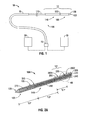
- FIG. 1 is a schematic diagram of an ablation system in accordance with an embodiment of the present disclosure
- FIG. 2A is a partial, longitudinal cross-sectional view of an embodiment of the energy applicator of the ablation system shown in FIG. 1 in accordance with the present disclosure
- FIG. 2B is a partial, longitudinal cross-sectional view of another embodiment of the energy applicator of the ablation system shown in FIG. 1 in accordance with the present disclosure
- FIG. 3 is an enlarged view of the indicated area of detail of FIG. 2B , showing the junction member disposed between the proximal and distal radiating portions, in accordance with the present disclosure
- FIG. 4A is an enlarged view of the indicated area of detail of FIG. 2A , showing the electrically-conductive member, in accordance with the present disclosure
- FIG. 4B is a cross-sectional view of another embodiment of the electrically-conductive member of FIG. 2A in accordance with the present disclosure
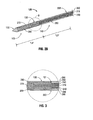
- FIG. 5 is a partial, perspective view of another embodiment of an energy applicator in accordance with the present disclosure shown with indicia graduation marks and an indicia alignment mark;
- FIG.6 is a diagrammatic representation of a radiation pattern of electromagnetic energy delivered into tissue by an energy applicator, such as the energy applicator of FIG. 5 , in accordance with the present disclosure
- FIG. 7 is a cross-sectional view of an embodiment of an energy applicator shown with a diagrammatic representation of an emitted radiation pattern in accordance with the present disclosure
- FIG. 8 is a graph showing simulation results for an embodiment of an energy applicator in accordance with the present disclosure.
- FIG. 9 is a graph showing simulation results for another embodiment of an energy applicator in accordance with the present disclosure.
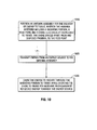
- FIG. 10 is a flowchart illustrating a method of directing energy to tissue in accordance with an embodiment of the present disclosure.
- proximal refers to that portion of the apparatus that is closer to the user and the term “distal” refers to that portion of the apparatus that is farther from the user.
- Electromagnetic energy is generally classified by increasing energy or decreasing wavelength into radio waves, microwaves, infrared, visible light, ultraviolet, X-rays and gamma-rays.
- microwave generally refers to electromagnetic waves in the frequency range of 300 megahertz (MHz) (3 x 10 8 cycles/second) to 300 gigahertz (GHz) (3 x 10 11 cycles/second).
- ablation procedure generally refers to any ablation procedure, such as microwave ablation, radio frequency (RF) ablation or microwave ablation assisted resection.
- transmission line generally refers to any transmission medium that can be used for the propagation of signals from one point to another.
- Various embodiments of the present disclosure provide electrosurgical devices for treating tissue and methods of directing electromagnetic radiation to a target volume of tissue.
- Embodiments may be implemented using electromagnetic radiation at microwave frequencies or at other frequencies.
- An electrosurgical system including an energy applicator, according to various embodiments, is designed and configured to operate between about 500 MHz and about 10 GHz with a directional radiation pattern.
- Various embodiments of the presently disclosed electrosurgical devices are suitable for microwave ablation and for use to pre-coagulate tissue for microwave ablation assisted surgical resection.
- various methods described hereinbelow are targeted toward microwave ablation and the complete destruction of target tissue, it is to be understood that methods for directing electromagnetic radiation may be used with other therapies in which the target tissue is partially destroyed or damaged, such as, for example, to prevent the conduction of electrical impulses within heart tissue.
- the teachings of the present disclosure may also apply to a monopole, helical, or other suitable type of microwave antenna.
- Various embodiments of the presently disclosed electrosurgical devices include an antenna assembly and a feedline having an inner and outer conductor for supplying signals to the antenna assembly, wherein the feedline and/or antenna assembly is provided with an electrically-conductive member (e.g., 295 shown in FIG. 2A ) electrically coupled to the outer conductor (e.g., 260 shown in FIG. 2A ), wherein the electrically-conductive member is configured to make contact with tissue (e.g., "T" shown in FIG. 6 ) during a procedure, e.g., an ablation procedure.
- tissue e.g., "T" shown in FIG. 6
- FIG. 1 shows an electrosurgical system 10, according to an embodiment of the present disclosure that includes an energy applicator or probe 100.
- Probe 100 generally includes an antenna assembly 12 having a radiating portion connected by a feedline 110 (or shaft) via a transmission line 15 to a connector 16, which may further operably connect the probe 100 to an electrosurgical power generating source 28, e.g., a microwave or RF electrosurgical generator.
- an electrosurgical power generating source 28 e.g., a microwave or RF electrosurgical generator.
- Feedline 110 may be formed from a suitable flexible, semi-rigid or rigid microwave conductive cable and may connect directly to an electrosurgical power generating source 28. Alternatively, the feedline 110 may electrically connect the antenna assembly 12 via the transmission line 15 to the electrosurgical power generating source 28. Feedline 110 may have a variable length from a proximal end of the antenna assembly 12 to a distal end of transmission line 15 ranging from a length of about one inch to about twelve inches. Feedline 110 may be formed of suitable electrically-conductive materials, e.g., copper, gold, silver or other conductive metals or metal alloys having similar conductivity values. Feedline 110 may be made of stainless steel, which generally offers the strength required to puncture tissue and/or skin.
- Conductive materials used to form the feedline 110 may be plated with other materials, e.g., other conductive materials, such as gold or silver, to improve their properties, e.g., to improve conductivity, decrease energy loss, etc.
- the feedline 110 includes stainless steel, and to improve the conductivity thereof, the stainless steel may be coated with a layer of a conductive material such as copper or gold.
- Feedline 110 may include an inner conductor, a dielectric material coaxially surrounding the inner conductor, and an outer conductor coaxially surrounding the dielectric material.
- Antenna assembly 12 may be formed from a portion of the inner conductor that extends distal of the feedline 110 into the antenna assembly 12.
- Feedline 110 may be cooled by fluid, e.g., saline, water or other suitable coolant fluid, to improve power handling, and may include a stainless steel catheter.
- the power generating source 28 is configured to provide microwave energy at an operational frequency from about 500 MHz to about 2500 MHz. In other embodiments, the power generating source 28 is configured to provide microwave energy at an operational frequency from about 500 MHz to about 10 GHz. Power generating source 28 may be configured to provide various frequencies of electromagnetic energy. Transmission line 15 may additionally, or alternatively, provide a conduit (not shown) configured to provide coolant fluid from a coolant source 18 to one or more components of the probe 100.
- an end cap or tapered portion 120 Located at the distal end of the antenna assembly 12 is an end cap or tapered portion 120, which may terminate in a sharp tip 123 to allow for insertion into tissue with minimal resistance.
- the end cap or tapered portion 120 may include other shapes, such as, for example, a tip 123 that is rounded, flat, square, hexagonal, or cylindroconical.
- the antenna assembly 12 includes a distal radiating portion 105 and a proximal radiating portion 140.
- a junction member 130 may be provided. Junction member 130, or portions thereof, may be disposed between the proximal and distal radiating portions, 140 and 105, respectively. In some embodiments, the distal and proximal radiating portions 105, 140 align at the junction member 130, which is generally made of a dielectric material, e.g., adhesives, and are also supported by the inner conductor that extends at least partially through the distal radiating portion 105.
- Junction member 130 may be formed from any suitable elastomeric or ceramic dielectric material by any suitable process.
- the junction member 130 is formed by over-molding and includes a thermoplastic elastomer, such as, for example, polyether block amide (e.g., PEBAX ® , manufactured by The Arkema Group of Colombes, France), polyetherimide (e.g., ULTEM ® and/or EXTEM ® , manufactured by SABIC Innovative Plastics of Saudi Arabia) and/or polyimide-based polymer (e.g., VESPEL ® , manufactured by E. I. du Pont de Nemours and Company of Wilmington, Delaware, United States).
- Junction member 130 may be formed using any suitable over-molding compound by any suitable process, and may include use of a ceramic substrate.
- the antenna assembly 12 may be provided with a coolant chamber (not shown).
- the junction member 130 may include coolant inflow and outflow ports (not shown) to facilitate the flow of coolant into, and out of, the coolant chamber. Examples of coolant chamber and coolant inflow and outflow port embodiments are disclosed in commonly assigned U.S. Patent Application Serial No. 12/401,268 filed on March 10, 2009 , entitled “COOLED DIELECTRICALLY BUFFERED MICROWAVE DIPOLE ANTENNA", and U.S. Pat. No. 7,311,703 , entitled “DEVICES AND METHODS FOR COOLING MICROWAVE ANTENNAS".
- the antenna assembly 12 may be provided with an outer jacket (not shown) disposed about the distal radiating portion 105, the junction 130 and/or the proximal radiating portion 140.
- the outer jacket may be formed of any suitable material, such as, for example, polymeric or ceramic materials.
- the outer jacket may be applied by any suitable method, such as, for example, heat shrinking, over-molding, coating, spraying dipping, powder coating, baking and/or film deposition.
- the outer jacket may be a water-cooled catheter formed of a material having low electrical conductivity.
- the probe 100 is inserted into or placed adjacent to tissue and microwave energy is supplied thereto.
- Ultrasound or computed tomography (CT) guidance may be used to accurately guide the probe 100 into the area of tissue to be treated.
- Probe 100 may be placed percutaneously or surgically, e.g., using conventional surgical techniques by surgical staff.
- a clinician may pre-determine the length of time that microwave energy is to be applied. Application duration may depend on many factors such as tumor size and location and whether the tumor was a secondary or primary cancer.
- the duration of microwave energy application using the probe 100 may depend on the progress of the heat distribution within the tissue area that is to be destroyed and/or the surrounding tissue.
- Single or multiple probes 100 may provide ablations in short procedure times, e.g., a few minutes, to destroy cancerous cells in the target tissue region.
- a plurality of probes 100 may be placed in variously-arranged configurations to substantially simultaneously ablate a target tissue region, making faster procedures possible. Multiple probes 100 can be used to synergistically create a large ablation or to ablate separate sites simultaneously. Tissue ablation size and geometry is influenced by a variety of factors, such as the energy applicator design, number of energy applicators used simultaneously, ablation time and wattage, and tissue characteristics.
- microwave energy having a wavelength, lambda ( ⁇ ) is transmitted through the antenna assembly 12, e.g., along the proximal and distal radiating portions 140, 105, and radiated into the surrounding medium, e.g., tissue.
- the length of the antenna for efficient radiation may be dependent on the effective wavelength ⁇ eff , which is dependent upon the dielectric properties of the medium being radiated.
- Antenna assembly 12 through which microwave energy is transmitted at a wavelength ⁇ may have differing effective wavelengths ⁇ eff depending upon the surrounding medium, e.g., liver tissue as opposed to breast tissue.
- an embodiment of the antenna assembly 12 of FIG. 1 (shown generally as 12A in FIG. 2A ) includes an inner conductor 210, an outer conductor 260, and may include a first dielectric material 240 separating the inner conductor 210 and the outer conductor 260.
- the inner conductor 210 is formed from a first electrically-conductive material (e.g., stainless steel) and the outer conductor 260 is formed from a second electrically-conductive material (e.g., copper).
- the outer conductor 260 coaxially surrounds the inner conductor 210 along the proximal radiating portion 140, and may coaxially surround the inner conductor 210 along a distal portion of the antenna assembly 12A.
- Inner conductor 210 and the outer conductor 260 may be formed from any suitable electrically-conductive material.
- First dielectric material 240 may be formed from any suitable dielectric material, including, but not limited to, ceramics, water, mica, polyethylene, polyethylene terephthalate, polyimide, polytetrafluoroethylene (a.k.a. PTFE or Teflon®, manufactured by E. I. du Pont de Nemours and Company of Wilmington, Delaware, United States), glass, metal oxides or other suitable insulator, and may be formed in any suitable manner.
- Antenna assembly 12A may be provided with a second dielectric material 280 surrounding the outer conductor 260, or portions thereof, and/or the junction member 130, or portions thereof.
- Second dielectric material 280 may be formed from any suitable dielectric material, and may have a thickness of about 0.001 inches to about 0.005 inches.
- the second dielectric material 280 is formed from a material with a dielectric constant different than the dielectric constant of the first dielectric material 240.
- the antenna assembly 12A is provided with a third dielectric material 290 disposed proximal to the second dielectric material 280 surrounding the outer conductor 260.
- Second dielectric material 280 and the third dielectric material 290 may be formed of the same material and/or may be formed in the same process.
- Third dielectric material 290 may be formed from any suitable dielectric material, and may be formed by any suitable process, e.g., over-molding processes or heat shrinking. Third dielectric material 290 may be formed from a material with a dielectric constant different than the dielectric constant of the second dielectric material 280 and/or the first dielectric material 240. As shown in FIG. 2A , the third dielectric material 290 may include a first segment 2901 and a second segment 2902 disposed proximal to the first segment 2901. The shape and size of the first segment 2901 and the second segment 2902 may be varied from the configuration depicted in FIG. 2A .
- the antenna assembly 12A includes a conductor end portion 270, which may be formed from any suitable electrically-conductive material.
- the conductor end portion 270 is coupled to the inner conductor 210 and may be formed of the same material as the inner conductor 210.
- the conductor end portion 270 may be spaced apart from the outer conductor 260 by the junction member 130 disposed therebetween. Tapered region 120, or portions thereof, may surround a portion of the conductor end portion 270.
- the conductor end portion 270 is substantially cylindrically shaped, and may be formed from stainless steel. The shape and size of the conductor end portion 270 may be varied from the configuration depicted in FIG. 2A .
- at least a portion of the conductor end portion 270 is surrounded by the second dielectric material 280.
- Antenna assembly 12 of FIG. 1 includes a feed point (e.g., 350 shown in FIG. 2A ) and a choke (e.g., "C" shown in FIG. 2A ) electrically coupleable to tissue, wherein the choke is spaced apart from and disposed proximal to the feed point.
- the antenna assembly 12A may include a second dielectric material 280 disposed around at least a portion of the distal portion of the outer conductor 260 and a third dielectric material 290 disposed around at least a portion of the proximal portion of the outer conductor 260, wherein the third dielectric material 290 includes an opening (e.g., 291 shown in FIG. 4A ) defined therein.
- the electrically-conductive member 295 is disposed in the opening 291 electrically coupled to the outer conductor 260 and configured to make contact with tissue (e.g., "T" shown in FIG. 6 ) during a procedure, e.g., an ablation procedure.
- tissue e.g., "T” shown in FIG. 6
- the choke “C” includes an electrically-conductive member 295 formed in a ring-like shape concentrically disposed around the outer conductor 260 at a proximal end of a first segment 2901 of the third dielectric material 290, having a length "L1".
- a second segment 2902 of the third dielectric material 290 may be disposed proximal to the electrically-conductive member 295.
- Electrical current present in tissue around the choke "C”, according to embodiments of the present disclosure may dissipate relatively quickly where the operational frequency lies in certain frequency bands, such as microwave, and electromagnetic radiation will generally be confined to the radiating portion of the antenna 12A. Electromagnetic radiation, if any, about the presently-disclosed choke “C", or ohmic heating due to dissipated current present along the choke "C” area, may be useful for track-ablation.
- the second dielectric material 280 has a thickness of about 0.001 inches to about 0.005 inches
- the first segment 2901 of the third dielectric material 290 has a thickness of about 0.010 inches, e.g., to improve electrical choke performance.
- the second segment 2902 may have a thickness different than the thickness of the first segment 2901.
- the shape and size of the opening 291 and the electrically-conductive member 295 may be varied from the configuration depicted in FIG. 2A .
- FIGS. 2B and 3 show another embodiment of the antenna assembly 12 of FIG. 1 (shown generally as 12B in FIG. 2B ) in accordance with the present disclosure that is similar to the antenna assembly 12A of FIG. 2A , except for the size, shape and/or location of the conductor end portion 270, the junction member 130, the second dielectric material 280 and the electrically-conductive member 295, and the length of the distal and proximal radiating sections.
- the distal end of the outer conductor 260 and the distal end of the first dielectric material 240 may be spaced apart by a gap (e.g., "G" shown in FIG. 3 ) from the proximal end of the junction member 130 to define a feed point 350 therebetween.
- a gap e.g., "G" shown in FIG. 3
- the feed point 350 is disposed a length "L2" from the distal end of the antenna assembly 12A
- the electrically-conductive member 295 is disposed a length "L1" from the proximal end of a proximal radiating section 140 defined by a length "L3".
- the length "L2" may be about one-half wavelength, defining a distal radiating section 105
- the length "L3" may be about one-half wavelength, defining a proximal radiating section 140.
- the length "L1" is about one-quarter wavelength.
- the feed point 350 may be disposed a length "L4" from the distal end of the antenna assembly 12B, and the electrically-conductive member 295 may be disposed a length "L5" from the feed point 350.
- the length "L4" may be about one-half wavelength, defining a distal radiating section 105
- the length "L5" may be about one-half wavelength, defining a proximal radiating section 140.
- antenna assembly 12A shown in FIGS. 2A and 4A includes a single, electrically-conductive member 295 positioned in the opening 291, various combinations of different numbers of electrically-conductive members, variously sized and variously spaced apart from each other, may be provided to the antenna assembly 12A.
- Antenna assembly 12A in accordance with embodiments of the present disclosure, may include a plurality of electrically-conductive members that are spaced apart from each other disposed in the third dielectric material 290 and/or the second dielectric material 280, wherein each electrically-conductive member is electrically coupled to the outer conductor 260 and configured to make contact with tissue.
- the electrically-conductive member 295 may include a protrusion portion 298 that protrudes outwardly relative to the outer surface "S" of the third dielectric material 290, e.g., to improve the contact between the electrically-conductive member 295 and tissue.
- Protruding portion 298 may have various shapes, such as generally semi-circular, bulbous, bowed, concave or convex shapes, and may be sized to improve the electrical contact with tissue.
- an ablation probe shown generally as 500 in FIG. 5 includes an antenna assembly 512 having a radiating portion 505 connected by a feedline 511 (or shaft) via a transmission line 15 to an energy source (e.g., 28 shown in FIG. 1 ).
- Antenna assembly 512 includes at least one substantially rectangular-shaped electrically-conductive member 595 configured to make contact with tissue. Electrically-conductive member 595 is similar to the electrically-conductive member 295 shown in FIG. 2A , except for its shape, and further description thereof is omitted in the interests of brevity.
- the ablation probe 500 includes an indicia alignment mark 510, e.g., a colored stripe, which is readily visible along the proximal end of the ablation probe 500.
- indicia alignment mark 510 is positioned such that the longitudinal axis of the alignment mark 510 substantially aligns with the longitudinal axis of the substantially rectangular-shaped electrically-conductive member 595, to provide a visual cue to the surgeon to allow orientation of the electrically-conductive member 595 to coincide with the indicia alignment mark 510.
- the visual assistance provided by the indicia alignment mark 510 may allow the surgeon to selectively position the electrically-conductive member 595 in tissue. As shown in FIG. 5 , one or more of the indicia graduation marks 580 may overlap the indicia alignment mark 510. The shape and size of the indicia alignment mark 510 and the indicia graduation marks 580 may be varied from the configurations depicted in FIG. 5 .
- Antenna assembly 512 is similar to the antenna assembly 12A shown in FIGS. 2A and 4A , except for the shape of the electrically-conductive member and the indicia graduation marks 580 and the indicia alignment mark 510, and further description thereof is omitted in the interests of brevity.
- FIG. 6 shows a diagrammatic representation of a radiation pattern "R" of electromagnetic energy delivered into tissue "T” by the ablation probe 500 of FIG. 5 .
- the ablation probe 500 is coupled to a transmission line 15 that may further connect the ablation probe 500 to a power generating source, e.g., a microwave or RF electrosurgical generator.
- Ablation probe 500 may be placed percutaneously or surgically.
- Ultrasound or computed tomography (CT) guidance may be used to accurately guide the ablation probe 500 into the area of tissue "T” to be treated.
- CT computed tomography
- the shape and size of the emitted radiation pattern "R" may be varied from the configuration depicted in FIG. 6 .
- FIG. 7 is a cross-sectional view of an embodiment of an electrosurgical device 700 shown with a diagrammatic representation of an emitted radiation pattern in accordance with the present disclosure. Electrosurgical device 700 shown in FIG. 7 is similar to the electrosurgical device 100 of FIGS. 1 and 2B through 4A and further description thereof is omitted in the interests of brevity.
- FIG.8 and 9 are S-parameter (scattering parameter) magnitude graphs displaying magnitude in decibels (dB) with respect to frequency.
- the illustrated results are based on simulations that modeled operation of embodiments of an energy applicator provided with a choke in accordance with the present disclosure.
- the graph shows a minimum at approximately 1.05 GHz ( ⁇ -33 dB).
- the minimum plotted on the graph can be interpreted as showing that the simulation generally modeled a resonant one-quarter wavelength antenna.
- FIG. 10 is a flowchart illustrating a method of directing energy to tissue according to an embodiment of the present disclosure.
- an antenna assembly e.g., 12 shown in FIG. 1
- the antenna assembly includes a radiating portion (e.g., 105 shown in FIG. 2A ), a feed point (e.g., 350 shown in FIG. 3 ), and a choke (e.g., "C” shown in FIG. 2A ) electrically coupleable to tissue, the choke spaced apart from and disposed proximal to the feed point.
- the antenna assembly may be inserted directly into tissue (e.g., "T" shown in FIG.
- the antenna assembly may be configured to operate with a directional radiation pattern.
- the radiating portion is configured for radiating energy in a broadside radiation pattern.
- step 1020 energy from an energy source (e.g., 28 shown in FIG. 1 ) is transmitted to the antenna assembly (e.g., 12 shown in FIG. 1 ).
- the energy source may be any suitable electrosurgical generator for generating an output signal.
- the energy source is a microwave energy source, and may be configured to provide microwave energy at an operational frequency from about 500 MHz to about 10 GHz.
- step 1030 the energy from the energy source is caused to radiate through the radiating portion to tissue while the choke is shorted to tissue for blocking propagation of reflected energy towards the energy source.
- the above-described electrosurgical devices for treating tissue and methods of directing electromagnetic radiation to a target volume of tissue may be used to provide directional microwave ablation, wherein the heating zone may be focused to one side of the electrosurgical device, thereby allowing clinicians to target small and/or hard tumors without having to penetrate the tumor directly or kill more healthy tissue than necessary.
- the presently disclosed electrosurgical devices may allow clinicians to avoid ablating critical structures, such as large vessels, healthy organs or vital membrane barriers, by placing the electrosurgical device between the tumor and critical structure and directing the electromagnetic radiation toward the tumor and away from the sensitive structure.
Abstract
Description
- The present disclosure relates to electrosurgical devices suitable for use in tissue ablation applications and, more particularly, to electrosurgical devices with a choke shorted to biological tissue and methods of directing electromagnetic radiation to tissue using the same.
- Treatment of certain diseases requires the destruction of malignant tissue growths, e.g., tumors. Electromagnetic radiation can be used to heat and destroy tumor cells. Treatment may involve inserting ablation probes into tissues where cancerous tumors have been identified. Once the probes are positioned, electromagnetic energy is passed through the probes into surrounding tissue.
- In the treatment of diseases such as cancer, certain types of tumor cells have been found to denature at elevated temperatures that are slightly lower than temperatures normally injurious to healthy cells. Known treatment methods, such as hyperthermia therapy, heat diseased cells to temperatures above 41° C while maintaining adjacent healthy cells below the temperature at which irreversible cell destruction occurs. These methods involve applying electromagnetic radiation to heat, ablate and/or coagulate tissue. Microwave energy is sometimes utilized to perform these methods. Other procedures utilizing electromagnetic radiation to heat tissue also include coagulation, cutting and/or ablation of tissue.
- Electrosurgical devices utilizing electromagnetic radiation have been developed for a variety of uses and applications. A number of devices are available that can be used to provide high bursts of energy for short periods of time to achieve cutting and coagulative effects on various tissues. There are a number of different types of apparatus that can be used to perform ablation procedures. Typically, microwave apparatus for use in ablation procedures include a microwave generator that functions as an energy source, and a microwave surgical instrument (e.g., microwave ablation probe) having an antenna assembly for directing the energy to the target tissue. The microwave generator and surgical instrument are typically operatively coupled by a cable assembly having a plurality of conductors for transmitting microwave energy from the generator to the instrument, and for communicating control, feedback and identification signals between the instrument and the generator.
- There are several types of microwave probes in use, e.g., monopole, dipole and helical, which may be used in tissue ablation applications. In monopole and dipole antenna assemblies, microwave energy generally radiates perpendicularly away from the axis of the conductor. Monopole antenna assemblies typically include a single, elongated conductor. A typical dipole antenna assembly includes two elongated conductors that are linearly aligned and positioned end-to-end relative to one another with an electrical insulator placed therebetween. Helical antenna assemblies include helically-shaped conductor configurations of various and dimensions, e.g., diameter and length. The main modes of operation of a helical antenna assembly are normal mode (broadside), in which the field radiated by the helix is maximum in a perpendicular plane to the helix axis, and axial mode (end fire), in which maximum radiation is along the helix axis.
- A microwave transmission line typically includes a long, thin inner conductor that extends along the longitudinal axis of the transmission line and is surrounded by a dielectric material and is further surrounded by an outer conductor around the dielectric material such that the outer conductor also extends along the transmission line axis. In one variation of an antenna, a waveguiding structure, such as a length of transmission line or coaxial cable, is provided with a plurality of openings through which energy "leaks" or radiates away from the guiding structure. This type of construction is typically referred to as a "leaky coaxial" or "leaky wave" antenna.
- During certain procedures, it can be difficult to assess the extent to which the microwave energy will radiate into the surrounding tissue, making it difficult to determine the area or volume of surrounding tissue that will be ablated.
- The present disclosure relates to a device for directing energy to tissue including a feedline and a radiating portion electrically coupled to the feedline. The radiating portion includes a distal radiating section and a proximal radiating section. The feedline includes an inner conductor, an outer conductor and a first dielectric material disposed therebetween. The device also includes a choke disposed around at least a portion of the feedline. The choke includes a second dielectric material disposed around at least a portion of the outer conductor, wherein the second dielectric material includes one or more openings defined therein, and an electrically-conductive member disposed in the one opening(s) electrically coupled to the outer conductor, wherein the electrically-conductive member is configured to contact tissue.
- The present disclosure also relates to ablation probe for providing energy to tissue including an inner conductor, an outer conductor coaxially surrounding the inner conductor, the outer conductor having a proximal portion and a distal portion. A first dielectric material is disposed between the inner conductor and the outer conductor, and a second dielectric material disposed around at least a portion of the distal portion of the outer conductor. The ablation probe also includes a third dielectric material disposed around the proximal portion of the outer conductor, wherein the third dielectric material includes an opening defined therein. An electrically-conductive member is disposed in the opening electrically coupled to the proximal portion of the outer conductor, wherein the electrically-conductive member is configured to contact tissue.
- The present disclosure also relates to a method of directing energy to tissue that includes the initial step of positioning an antenna assembly for delivery of energy to tissue. The antenna assembly includes a radiating portion, a feed point, and a choke electrically coupleable to tissue, wherein the choke is spaced apart from and disposed proximal to the feed point. The method also includes the steps of transmitting energy from an energy source to the antenna assembly, and causing the energy to radiate through the radiating portion to tissue while shorting the choke to tissue for blocking propagation of reflected energy towards the energy source.
- Objects and features of the presently disclosed antenna assemblies will become apparent to those of ordinary skill in the art when descriptions of various embodiments thereof are read with reference to the accompanying drawings, of which:
-
FIG. 1 is a schematic diagram of an ablation system in accordance with an embodiment of the present disclosure; -
FIG. 2A is a partial, longitudinal cross-sectional view of an embodiment of the energy applicator of the ablation system shown inFIG. 1 in accordance with the present disclosure; -
FIG. 2B is a partial, longitudinal cross-sectional view of another embodiment of the energy applicator of the ablation system shown inFIG. 1 in accordance with the present disclosure; -
FIG. 3 is an enlarged view of the indicated area of detail ofFIG. 2B , showing the junction member disposed between the proximal and distal radiating portions, in accordance with the present disclosure; -
FIG. 4A is an enlarged view of the indicated area of detail ofFIG. 2A , showing the electrically-conductive member, in accordance with the present disclosure; -
FIG. 4B is a cross-sectional view of another embodiment of the electrically-conductive member ofFIG. 2A in accordance with the present disclosure; -
FIG. 5 is a partial, perspective view of another embodiment of an energy applicator in accordance with the present disclosure shown with indicia graduation marks and an indicia alignment mark; -
FIG.6 is a diagrammatic representation of a radiation pattern of electromagnetic energy delivered into tissue by an energy applicator, such as the energy applicator ofFIG. 5 , in accordance with the present disclosure; -
FIG. 7 is a cross-sectional view of an embodiment of an energy applicator shown with a diagrammatic representation of an emitted radiation pattern in accordance with the present disclosure; -
FIG. 8 is a graph showing simulation results for an embodiment of an energy applicator in accordance with the present disclosure; -
FIG. 9 is a graph showing simulation results for another embodiment of an energy applicator in accordance with the present disclosure; and -
FIG. 10 is a flowchart illustrating a method of directing energy to tissue in accordance with an embodiment of the present disclosure. - Hereinafter, embodiments of the presently disclosed electrosurgical devices will be described with reference to the accompanying drawings. Like reference numerals may refer to similar or identical elements throughout the description of the figures. As shown in the drawings and as used in this description, and as is traditional when referring to relative positioning on an object, the term "proximal" refers to that portion of the apparatus that is closer to the user and the term "distal" refers to that portion of the apparatus that is farther from the user.
- Electromagnetic energy is generally classified by increasing energy or decreasing wavelength into radio waves, microwaves, infrared, visible light, ultraviolet, X-rays and gamma-rays. As it is used in this description, "microwave" generally refers to electromagnetic waves in the frequency range of 300 megahertz (MHz) (3 x 10⁸ cycles/second) to 300 gigahertz (GHz) (3 x 10¹¹ cycles/second). As it is used in this description, "ablation procedure" generally refers to any ablation procedure, such as microwave ablation, radio frequency (RF) ablation or microwave ablation assisted resection. As it is used in this description, "transmission line" generally refers to any transmission medium that can be used for the propagation of signals from one point to another.
- Various embodiments of the present disclosure provide electrosurgical devices for treating tissue and methods of directing electromagnetic radiation to a target volume of tissue. Embodiments may be implemented using electromagnetic radiation at microwave frequencies or at other frequencies. An electrosurgical system including an energy applicator, according to various embodiments, is designed and configured to operate between about 500 MHz and about 10 GHz with a directional radiation pattern.
- Various embodiments of the presently disclosed electrosurgical devices are suitable for microwave ablation and for use to pre-coagulate tissue for microwave ablation assisted surgical resection. Although various methods described hereinbelow are targeted toward microwave ablation and the complete destruction of target tissue, it is to be understood that methods for directing electromagnetic radiation may be used with other therapies in which the target tissue is partially destroyed or damaged, such as, for example, to prevent the conduction of electrical impulses within heart tissue. In addition, although the following description describes the use of a dipole microwave antenna, the teachings of the present disclosure may also apply to a monopole, helical, or other suitable type of microwave antenna.
- Various embodiments of the presently disclosed electrosurgical devices include an antenna assembly and a feedline having an inner and outer conductor for supplying signals to the antenna assembly, wherein the feedline and/or antenna assembly is provided with an electrically-conductive member (e.g., 295 shown in
FIG. 2A ) electrically coupled to the outer conductor (e.g., 260 shown inFIG. 2A ), wherein the electrically-conductive member is configured to make contact with tissue (e.g., "T" shown inFIG. 6 ) during a procedure, e.g., an ablation procedure. -
FIG. 1 shows anelectrosurgical system 10, according to an embodiment of the present disclosure that includes an energy applicator orprobe 100.Probe 100 generally includes anantenna assembly 12 having a radiating portion connected by a feedline 110 (or shaft) via atransmission line 15 to aconnector 16, which may further operably connect theprobe 100 to an electrosurgicalpower generating source 28, e.g., a microwave or RF electrosurgical generator. -
Feedline 110 may be formed from a suitable flexible, semi-rigid or rigid microwave conductive cable and may connect directly to an electrosurgicalpower generating source 28. Alternatively, thefeedline 110 may electrically connect theantenna assembly 12 via thetransmission line 15 to the electrosurgicalpower generating source 28.Feedline 110 may have a variable length from a proximal end of theantenna assembly 12 to a distal end oftransmission line 15 ranging from a length of about one inch to about twelve inches.Feedline 110 may be formed of suitable electrically-conductive materials, e.g., copper, gold, silver or other conductive metals or metal alloys having similar conductivity values.Feedline 110 may be made of stainless steel, which generally offers the strength required to puncture tissue and/or skin. Conductive materials used to form thefeedline 110 may be plated with other materials, e.g., other conductive materials, such as gold or silver, to improve their properties, e.g., to improve conductivity, decrease energy loss, etc. In some embodiments, thefeedline 110 includes stainless steel, and to improve the conductivity thereof, the stainless steel may be coated with a layer of a conductive material such as copper or gold.Feedline 110 may include an inner conductor, a dielectric material coaxially surrounding the inner conductor, and an outer conductor coaxially surrounding the dielectric material.Antenna assembly 12 may be formed from a portion of the inner conductor that extends distal of thefeedline 110 into theantenna assembly 12.Feedline 110 may be cooled by fluid, e.g., saline, water or other suitable coolant fluid, to improve power handling, and may include a stainless steel catheter. - In some embodiments, the
power generating source 28 is configured to provide microwave energy at an operational frequency from about 500 MHz to about 2500 MHz. In other embodiments, thepower generating source 28 is configured to provide microwave energy at an operational frequency from about 500 MHz to about 10 GHz.Power generating source 28 may be configured to provide various frequencies of electromagnetic energy.Transmission line 15 may additionally, or alternatively, provide a conduit (not shown) configured to provide coolant fluid from acoolant source 18 to one or more components of theprobe 100. - Located at the distal end of the
antenna assembly 12 is an end cap or taperedportion 120, which may terminate in asharp tip 123 to allow for insertion into tissue with minimal resistance. The end cap or taperedportion 120 may include other shapes, such as, for example, atip 123 that is rounded, flat, square, hexagonal, or cylindroconical. - In some variations, the
antenna assembly 12 includes adistal radiating portion 105 and aproximal radiating portion 140. Ajunction member 130 may be provided.Junction member 130, or portions thereof, may be disposed between the proximal and distal radiating portions, 140 and 105, respectively. In some embodiments, the distal and proximal radiatingportions junction member 130, which is generally made of a dielectric material, e.g., adhesives, and are also supported by the inner conductor that extends at least partially through thedistal radiating portion 105.Junction member 130 may be formed from any suitable elastomeric or ceramic dielectric material by any suitable process. In some embodiments, thejunction member 130 is formed by over-molding and includes a thermoplastic elastomer, such as, for example, polyether block amide (e.g., PEBAX®, manufactured by The Arkema Group of Colombes, France), polyetherimide (e.g., ULTEM® and/or EXTEM®, manufactured by SABIC Innovative Plastics of Saudi Arabia) and/or polyimide-based polymer (e.g., VESPEL®, manufactured by E. I. du Pont de Nemours and Company of Wilmington, Delaware, United States).Junction member 130 may be formed using any suitable over-molding compound by any suitable process, and may include use of a ceramic substrate. - In some embodiments, the
antenna assembly 12 may be provided with a coolant chamber (not shown). Additionally, thejunction member 130 may include coolant inflow and outflow ports (not shown) to facilitate the flow of coolant into, and out of, the coolant chamber. Examples of coolant chamber and coolant inflow and outflow port embodiments are disclosed in commonly assignedU.S. Patent Application Serial No. 12/401,268 filed on March 10, 2009 U.S. Pat. No. 7,311,703 , entitled "DEVICES AND METHODS FOR COOLING MICROWAVE ANTENNAS". - In some embodiments, the
antenna assembly 12 may be provided with an outer jacket (not shown) disposed about thedistal radiating portion 105, thejunction 130 and/or theproximal radiating portion 140. The outer jacket may be formed of any suitable material, such as, for example, polymeric or ceramic materials. The outer jacket may be applied by any suitable method, such as, for example, heat shrinking, over-molding, coating, spraying dipping, powder coating, baking and/or film deposition. The outer jacket may be a water-cooled catheter formed of a material having low electrical conductivity. - During microwave ablation, e.g., using the
electrosurgical system 10, theprobe 100 is inserted into or placed adjacent to tissue and microwave energy is supplied thereto. Ultrasound or computed tomography (CT) guidance may be used to accurately guide theprobe 100 into the area of tissue to be treated.Probe 100 may be placed percutaneously or surgically, e.g., using conventional surgical techniques by surgical staff. A clinician may pre-determine the length of time that microwave energy is to be applied. Application duration may depend on many factors such as tumor size and location and whether the tumor was a secondary or primary cancer. The duration of microwave energy application using theprobe 100 may depend on the progress of the heat distribution within the tissue area that is to be destroyed and/or the surrounding tissue. Single ormultiple probes 100 may provide ablations in short procedure times, e.g., a few minutes, to destroy cancerous cells in the target tissue region. - A plurality of
probes 100 may be placed in variously-arranged configurations to substantially simultaneously ablate a target tissue region, making faster procedures possible.Multiple probes 100 can be used to synergistically create a large ablation or to ablate separate sites simultaneously. Tissue ablation size and geometry is influenced by a variety of factors, such as the energy applicator design, number of energy applicators used simultaneously, ablation time and wattage, and tissue characteristics. - In operation, microwave energy having a wavelength, lambda (λ), is transmitted through the
antenna assembly 12, e.g., along the proximal anddistal radiating portions Antenna assembly 12 through which microwave energy is transmitted at a wavelength λ may have differing effective wavelengths λeff depending upon the surrounding medium, e.g., liver tissue as opposed to breast tissue. - Referring to
FIGS. 2A and4A , an embodiment of theantenna assembly 12 ofFIG. 1 (shown generally as 12A inFIG. 2A ) includes aninner conductor 210, anouter conductor 260, and may include a firstdielectric material 240 separating theinner conductor 210 and theouter conductor 260. In some embodiments, theinner conductor 210 is formed from a first electrically-conductive material (e.g., stainless steel) and theouter conductor 260 is formed from a second electrically-conductive material (e.g., copper). In some embodiments, theouter conductor 260 coaxially surrounds theinner conductor 210 along theproximal radiating portion 140, and may coaxially surround theinner conductor 210 along a distal portion of theantenna assembly 12A.Inner conductor 210 and theouter conductor 260 may be formed from any suitable electrically-conductive material. - First
dielectric material 240 may be formed from any suitable dielectric material, including, but not limited to, ceramics, water, mica, polyethylene, polyethylene terephthalate, polyimide, polytetrafluoroethylene (a.k.a. PTFE or Teflon®, manufactured by E. I. du Pont de Nemours and Company of Wilmington, Delaware, United States), glass, metal oxides or other suitable insulator, and may be formed in any suitable manner.Antenna assembly 12A may be provided with a seconddielectric material 280 surrounding theouter conductor 260, or portions thereof, and/or thejunction member 130, or portions thereof. Seconddielectric material 280 may be formed from any suitable dielectric material, and may have a thickness of about 0.001 inches to about 0.005 inches. In some embodiments, the seconddielectric material 280 is formed from a material with a dielectric constant different than the dielectric constant of the firstdielectric material 240. In the embodiment shown inFIG. 2A , theantenna assembly 12A is provided with a thirddielectric material 290 disposed proximal to the seconddielectric material 280 surrounding theouter conductor 260. Seconddielectric material 280 and the thirddielectric material 290 may be formed of the same material and/or may be formed in the same process. - Third
dielectric material 290 may be formed from any suitable dielectric material, and may be formed by any suitable process, e.g., over-molding processes or heat shrinking. Thirddielectric material 290 may be formed from a material with a dielectric constant different than the dielectric constant of the seconddielectric material 280 and/or the firstdielectric material 240. As shown inFIG. 2A , the thirddielectric material 290 may include afirst segment 2901 and asecond segment 2902 disposed proximal to thefirst segment 2901. The shape and size of thefirst segment 2901 and thesecond segment 2902 may be varied from the configuration depicted inFIG. 2A . - In some embodiments, the
antenna assembly 12A includes aconductor end portion 270, which may be formed from any suitable electrically-conductive material. In some embodiments, theconductor end portion 270 is coupled to theinner conductor 210 and may be formed of the same material as theinner conductor 210. In some embodiments, theconductor end portion 270 may be spaced apart from theouter conductor 260 by thejunction member 130 disposed therebetween.Tapered region 120, or portions thereof, may surround a portion of theconductor end portion 270. In some embodiments, theconductor end portion 270 is substantially cylindrically shaped, and may be formed from stainless steel. The shape and size of theconductor end portion 270 may be varied from the configuration depicted inFIG. 2A . In some embodiments, at least a portion of theconductor end portion 270 is surrounded by the seconddielectric material 280. -
Antenna assembly 12 ofFIG. 1 , according to various embodiments, includes a feed point (e.g., 350 shown inFIG. 2A ) and a choke (e.g., "C" shown inFIG. 2A ) electrically coupleable to tissue, wherein the choke is spaced apart from and disposed proximal to the feed point. In some embodiments, theantenna assembly 12A may include a seconddielectric material 280 disposed around at least a portion of the distal portion of theouter conductor 260 and a thirddielectric material 290 disposed around at least a portion of the proximal portion of theouter conductor 260, wherein the thirddielectric material 290 includes an opening (e.g., 291 shown inFIG. 4A ) defined therein. In various embodiments, the electrically-conductive member 295 is disposed in theopening 291 electrically coupled to theouter conductor 260 and configured to make contact with tissue (e.g., "T" shown inFIG. 6 ) during a procedure, e.g., an ablation procedure. - In the embodiment shown in cross-section in
FIG. 2A , the choke "C" includes an electrically-conductive member 295 formed in a ring-like shape concentrically disposed around theouter conductor 260 at a proximal end of afirst segment 2901 of the thirddielectric material 290, having a length "L1". Asecond segment 2902 of the thirddielectric material 290 may be disposed proximal to the electrically-conductive member 295. Electrical current present in tissue around the choke "C", according to embodiments of the present disclosure, may dissipate relatively quickly where the operational frequency lies in certain frequency bands, such as microwave, and electromagnetic radiation will generally be confined to the radiating portion of theantenna 12A. Electromagnetic radiation, if any, about the presently-disclosed choke "C", or ohmic heating due to dissipated current present along the choke "C" area, may be useful for track-ablation. - In some embodiments, the second
dielectric material 280 has a thickness of about 0.001 inches to about 0.005 inches, and thefirst segment 2901 of the thirddielectric material 290 has a thickness of about 0.010 inches, e.g., to improve electrical choke performance. Thesecond segment 2902 may have a thickness different than the thickness of thefirst segment 2901. The shape and size of theopening 291 and the electrically-conductive member 295 may be varied from the configuration depicted inFIG. 2A . -
FIGS. 2B and 3 show another embodiment of theantenna assembly 12 ofFIG. 1 (shown generally as 12B inFIG. 2B ) in accordance with the present disclosure that is similar to theantenna assembly 12A ofFIG. 2A , except for the size, shape and/or location of theconductor end portion 270, thejunction member 130, the seconddielectric material 280 and the electrically-conductive member 295, and the length of the distal and proximal radiating sections. As cooperatively shown inFIGS. 2A ,2B and 3 , the distal end of theouter conductor 260 and the distal end of the firstdielectric material 240 may be spaced apart by a gap (e.g., "G" shown inFIG. 3 ) from the proximal end of thejunction member 130 to define afeed point 350 therebetween. - In the embodiment shown in
FIG. 2A , thefeed point 350 is disposed a length "L2" from the distal end of theantenna assembly 12A, and the electrically-conductive member 295 is disposed a length "L1" from the proximal end of aproximal radiating section 140 defined by a length "L3". In some embodiments, the length "L2" may be about one-half wavelength, defining adistal radiating section 105, and the length "L3" may be about one-half wavelength, defining aproximal radiating section 140. In some embodiments, the length "L1" is about one-quarter wavelength. - As shown in
FIG. 2B , thefeed point 350 may be disposed a length "L4" from the distal end of theantenna assembly 12B, and the electrically-conductive member 295 may be disposed a length "L5" from thefeed point 350. In some embodiments, the length "L4" may be about one-half wavelength, defining adistal radiating section 105, and the length "L5" may be about one-half wavelength, defining aproximal radiating section 140. - Although the
antenna assembly 12A shown inFIGS. 2A and4A includes a single, electrically-conductive member 295 positioned in theopening 291, various combinations of different numbers of electrically-conductive members, variously sized and variously spaced apart from each other, may be provided to theantenna assembly 12A.Antenna assembly 12A, in accordance with embodiments of the present disclosure, may include a plurality of electrically-conductive members that are spaced apart from each other disposed in the thirddielectric material 290 and/or the seconddielectric material 280, wherein each electrically-conductive member is electrically coupled to theouter conductor 260 and configured to make contact with tissue. - As shown in
FIG. 4B , the electrically-conductive member 295 may include aprotrusion portion 298 that protrudes outwardly relative to the outer surface "S" of the thirddielectric material 290, e.g., to improve the contact between the electrically-conductive member 295 and tissue. Protrudingportion 298 may have various shapes, such as generally semi-circular, bulbous, bowed, concave or convex shapes, and may be sized to improve the electrical contact with tissue. - According to an embodiment of the present disclosure, an ablation probe shown generally as 500 in
FIG. 5 includes anantenna assembly 512 having a radiatingportion 505 connected by a feedline 511 (or shaft) via atransmission line 15 to an energy source (e.g., 28 shown inFIG. 1 ).Antenna assembly 512 includes at least one substantially rectangular-shaped electrically-conductive member 595 configured to make contact with tissue. Electrically-conductive member 595 is similar to the electrically-conductive member 295 shown inFIG. 2A , except for its shape, and further description thereof is omitted in the interests of brevity. - In the embodiment shown in
FIG. 5 , theablation probe 500 includes anindicia alignment mark 510, e.g., a colored stripe, which is readily visible along the proximal end of theablation probe 500.indicia alignment mark 510 is positioned such that the longitudinal axis of thealignment mark 510 substantially aligns with the longitudinal axis of the substantially rectangular-shaped electrically-conductive member 595, to provide a visual cue to the surgeon to allow orientation of the electrically-conductive member 595 to coincide with theindicia alignment mark 510. The visual assistance provided by theindicia alignment mark 510, alone or in combination with the indicia graduation marks 580, according to embodiments of the present disclosure, may allow the surgeon to selectively position the electrically-conductive member 595 in tissue. As shown inFIG. 5 , one or more of the indicia graduation marks 580 may overlap theindicia alignment mark 510. The shape and size of theindicia alignment mark 510 and the indicia graduation marks 580 may be varied from the configurations depicted inFIG. 5 .Antenna assembly 512 is similar to theantenna assembly 12A shown inFIGS. 2A and4A , except for the shape of the electrically-conductive member and the indicia graduation marks 580 and theindicia alignment mark 510, and further description thereof is omitted in the interests of brevity. -
FIG. 6 shows a diagrammatic representation of a radiation pattern "R" of electromagnetic energy delivered into tissue "T" by theablation probe 500 ofFIG. 5 . As shown inFIG. 6 , theablation probe 500 is coupled to atransmission line 15 that may further connect theablation probe 500 to a power generating source, e.g., a microwave or RF electrosurgical generator.Ablation probe 500 may be placed percutaneously or surgically. Ultrasound or computed tomography (CT) guidance may be used to accurately guide theablation probe 500 into the area of tissue "T" to be treated. The shape and size of the emitted radiation pattern "R" may be varied from the configuration depicted inFIG. 6 . -
FIG. 7 is a cross-sectional view of an embodiment of anelectrosurgical device 700 shown with a diagrammatic representation of an emitted radiation pattern in accordance with the present disclosure.Electrosurgical device 700 shown inFIG. 7 is similar to theelectrosurgical device 100 ofFIGS. 1 and2B through 4A and further description thereof is omitted in the interests of brevity. -
FIG.8 and 9 are S-parameter (scattering parameter) magnitude graphs displaying magnitude in decibels (dB) with respect to frequency. The illustrated results are based on simulations that modeled operation of embodiments of an energy applicator provided with a choke in accordance with the present disclosure. InFIG. 8 , the graph shows a minimum at approximately 1.05 GHz (~ -33 dB). The minimum plotted on the graph can be interpreted as showing that the simulation generally modeled a resonant one-quarter wavelength antenna. The results illustrated inFIG. 9 , where the graph shows a minimum at approximately 915 MHz (- -27 dB), were obtained by increasing the length of the radiating portion of the energy applicator to match it to the desired 915 MHz, causing the energy applicator to become resonant at one-half wavelength. -
FIG. 10 is a flowchart illustrating a method of directing energy to tissue according to an embodiment of the present disclosure. Instep 1010, an antenna assembly (e.g., 12 shown inFIG. 1 ) is positioned for delivery of energy to tissue, wherein the antenna assembly includes a radiating portion (e.g., 105 shown inFIG. 2A ), a feed point (e.g., 350 shown inFIG. 3 ), and a choke (e.g., "C" shown inFIG. 2A ) electrically coupleable to tissue, the choke spaced apart from and disposed proximal to the feed point. The antenna assembly may be inserted directly into tissue (e.g., "T" shown inFIG. 6 ), inserted through a lumen, e.g., a vein, needle or catheter, placed into the body during surgery by a clinician, or positioned in the body by other suitable methods. The antenna assembly may be configured to operate with a directional radiation pattern. In some embodiments, the radiating portion is configured for radiating energy in a broadside radiation pattern. - In
step 1020, energy from an energy source (e.g., 28 shown inFIG. 1 ) is transmitted to the antenna assembly (e.g., 12 shown inFIG. 1 ). For example, the energy source may be any suitable electrosurgical generator for generating an output signal. In some embodiments, the energy source is a microwave energy source, and may be configured to provide microwave energy at an operational frequency from about 500 MHz to about 10 GHz. - In
step 1030, the energy from the energy source is caused to radiate through the radiating portion to tissue while the choke is shorted to tissue for blocking propagation of reflected energy towards the energy source. - The above-described electrosurgical devices for treating tissue and methods of directing electromagnetic radiation to a target volume of tissue may be used to provide directional microwave ablation, wherein the heating zone may be focused to one side of the electrosurgical device, thereby allowing clinicians to target small and/or hard tumors without having to penetrate the tumor directly or kill more healthy tissue than necessary. The presently disclosed electrosurgical devices may allow clinicians to avoid ablating critical structures, such as large vessels, healthy organs or vital membrane barriers, by placing the electrosurgical device between the tumor and critical structure and directing the electromagnetic radiation toward the tumor and away from the sensitive structure.
- Although embodiments have been described in detail with reference to the accompanying drawings for the purpose of illustration and description, it is to be understood that the inventive processes and apparatus are not to be construed as limited thereby. It will be apparent to those of ordinary skill in the art that various modifications to the foregoing embodiments may be made without departing from the scope of the disclosure.
Claims (11)
- A device for directing energy to tissue, comprising:a feedline including an inner conductor, an outer conductor and a first dielectric material disposed therebetween;a radiating portion electrically coupled to the feedline, the radiating portion having a distal radiating section and a proximal radiating section; anda choke disposed around at least a portion of the feedline, the choke including:a second dielectric material disposed around at least a portion of the outer conductor, wherein the second dielectric material includes at least one opening defined therein; andan electrically-conductive member disposed in the at least one opening electrically coupled to the outer conductor, wherein the electrically-conductive member is configured to contact tissue.
- The device of claim 1, wherein the electrically-conductive member is positioned about one-quarter of a wavelength from a proximal end of the proximal radiating section.
- The device of claim 2, wherein the electrically-conductive member is formed in a ring-like shape concentrically disposed around the outer conductor.
- The device of claim 1, wherein the electrically-conductive member includes a protrusion portion that protrudes outwardly relative to an outer surface of the second dielectric material.
- The device of claim 1, wherein the proximal radiating section includes at least a portion of the inner conductor and the first dielectric material and the distal radiating section includes a conductive element.
- An ablation probe for providing energy to tissue, comprising:an inner conductor;an outer conductor coaxially surrounding the inner conductor, the outer conductor having a proximal portion and a distal portion;a first dielectric material disposed between the inner conductor and the outer conductor;a second dielectric material disposed around at least a portion of the distal portion of the outer conductor;a third dielectric material disposed around the proximal portion of the outer conductor, wherein the third dielectric material includes an opening defined therein; andan electrically-conductive member disposed in the opening electrically coupled to the proximal portion of the outer conductor, wherein the electrically-conductive member is configured to contact tissue.
- The ablation probe of claim 6, further comprising:a feed point defined by the inner conductor and the outer conductor; anda radiating portion electrically coupled to the feed point at a point distal to the feed point.
- The ablation probe of claim 7, wherein the feed point is positioned about one-half of a wavelength from a distal end of the radiating portion.
- The ablation probe of claim 7, wherein the electrically-conductive member is positioned about one-half of a wavelength from the feed point.
- The ablation probe of claim 6, wherein the electrically-conductive member is positioned about one-quarter of a wavelength from a proximal end of the proximal radiating section.
- The ablation probe of claim 6, wherein the electrically-conductive member includes a protrusion portion that protrudes outwardly relative to an outer surface of the third dielectric material.
Applications Claiming Priority (1)
| Application Number | Priority Date | Filing Date | Title |
|---|---|---|---|
| US12/701,030 US8491579B2 (en) | 2010-02-05 | 2010-02-05 | Electrosurgical devices with choke shorted to biological tissue |
Publications (2)
| Publication Number | Publication Date |
|---|---|
| EP2353645A1 true EP2353645A1 (en) | 2011-08-10 |
| EP2353645B1 EP2353645B1 (en) | 2013-01-16 |
Family
ID=44022029
Family Applications (1)
| Application Number | Title | Priority Date | Filing Date |
|---|---|---|---|
| EP11000913A Not-in-force EP2353645B1 (en) | 2010-02-05 | 2011-02-04 | Electrosurgical devices with choke shorted to biological tissue |
Country Status (3)
| Country | Link |
|---|---|
| US (2) | US8491579B2 (en) |
| EP (1) | EP2353645B1 (en) |
| JP (1) | JP2011161224A (en) |
Cited By (2)
| Publication number | Priority date | Publication date | Assignee | Title |
|---|---|---|---|---|
| CN105769338A (en) * | 2016-04-11 | 2016-07-20 | 上海大学 | Microwave ablation probe for interventional therapy of liver cancer |
| CN114652434A (en) * | 2022-02-16 | 2022-06-24 | 电子科技大学 | Multi-window microwave ablation method and device based on MEMS micro-needle beam |
Families Citing this family (33)
| Publication number | Priority date | Publication date | Assignee | Title |
|---|---|---|---|---|
| US7553309B2 (en) | 2004-10-08 | 2009-06-30 | Covidien Ag | Electrosurgical system employing multiple electrodes and method thereof |
| US9375246B2 (en) | 2007-01-19 | 2016-06-28 | Covidien Lp | System and method of using thermal and electrical conductivity of tissue |
| US8292881B2 (en) | 2009-05-27 | 2012-10-23 | Vivant Medical, Inc. | Narrow gauge high strength choked wet tip microwave ablation antenna |
| US8235981B2 (en) | 2009-06-02 | 2012-08-07 | Vivant Medical, Inc. | Electrosurgical devices with directional radiation pattern |
| US8552915B2 (en) | 2009-06-19 | 2013-10-08 | Covidien Lp | Microwave ablation antenna radiation detector |
| US8430871B2 (en) | 2009-10-28 | 2013-04-30 | Covidien Lp | System and method for monitoring ablation size |
| US8469953B2 (en) | 2009-11-16 | 2013-06-25 | Covidien Lp | Twin sealing chamber hub |
| US8728067B2 (en) | 2010-03-08 | 2014-05-20 | Covidien Lp | Microwave antenna probe having a deployable ground plane |
| US9561076B2 (en) | 2010-05-11 | 2017-02-07 | Covidien Lp | Electrosurgical devices with balun structure for air exposure of antenna radiating section and method of directing energy to tissue using same |
| US9192436B2 (en) | 2010-05-25 | 2015-11-24 | Covidien Lp | Flow rate verification monitor for fluid-cooled microwave ablation probe |
| US8652127B2 (en) | 2010-05-26 | 2014-02-18 | Covidien Lp | System and method for chemically cooling an ablation antenna |
| US9241762B2 (en) | 2010-06-03 | 2016-01-26 | Covidien Lp | Specific absorption rate measurement and energy-delivery device characterization using image analysis |
| US8672933B2 (en) | 2010-06-30 | 2014-03-18 | Covidien Lp | Microwave antenna having a reactively-loaded loop configuration |
| US10588684B2 (en) | 2010-07-19 | 2020-03-17 | Covidien Lp | Hydraulic conductivity monitoring to initiate tissue division |
| US9055957B2 (en) | 2010-12-23 | 2015-06-16 | Covidien Lp | Microwave field-detecting needle assemblies, methods of manufacturing same, methods of adjusting an ablation field radiating into tissue using same, and systems including same |
| US9770294B2 (en) | 2011-01-05 | 2017-09-26 | Covidien Lp | Energy-delivery devices with flexible fluid-cooled shaft, inflow/outflow junctions suitable for use with same, and systems including same |
| US9028476B2 (en) | 2011-02-03 | 2015-05-12 | Covidien Lp | Dual antenna microwave resection and ablation device, system and method of use |
| US10335230B2 (en) | 2011-03-09 | 2019-07-02 | Covidien Lp | Systems for thermal-feedback-controlled rate of fluid flow to fluid-cooled antenna assembly and methods of directing energy to tissue using same |
| US9901398B2 (en) | 2012-06-29 | 2018-02-27 | Covidien Lp | Microwave antenna probes |
| US9259269B2 (en) | 2012-08-07 | 2016-02-16 | Covidien Lp | Microwave ablation catheter and method of utilizing the same |
| US9668802B2 (en) | 2012-10-02 | 2017-06-06 | Covidien Lp | Devices and methods for optical detection of tissue contact |
| US9993283B2 (en) | 2012-10-02 | 2018-06-12 | Covidien Lp | Selectively deformable ablation device |
| US9901399B2 (en) | 2012-12-17 | 2018-02-27 | Covidien Lp | Ablation probe with tissue sensing configuration |
| WO2014160931A1 (en) | 2013-03-29 | 2014-10-02 | Covidien Lp | Step-down coaxial microwave ablation applicators and methods for manufacturing same |
| ITMO20130234A1 (en) * | 2013-08-08 | 2015-02-09 | Hs Hospital Service Spa | ANTENNA FOR A MICROWAVE DEVICE FOR FABRIC EXTRACTION |
| US10624697B2 (en) | 2014-08-26 | 2020-04-21 | Covidien Lp | Microwave ablation system |
| US10813691B2 (en) | 2014-10-01 | 2020-10-27 | Covidien Lp | Miniaturized microwave ablation assembly |
| US10813692B2 (en) | 2016-02-29 | 2020-10-27 | Covidien Lp | 90-degree interlocking geometry for introducer for facilitating deployment of microwave radiating catheter |
| US11064904B2 (en) | 2016-02-29 | 2021-07-20 | Extremity Development Company, Llc | Smart drill, jig, and method of orthopedic surgery |
| US10376309B2 (en) | 2016-08-02 | 2019-08-13 | Covidien Lp | Ablation cable assemblies and a method of manufacturing the same |
| US11065053B2 (en) | 2016-08-02 | 2021-07-20 | Covidien Lp | Ablation cable assemblies and a method of manufacturing the same |
| US11197715B2 (en) | 2016-08-02 | 2021-12-14 | Covidien Lp | Ablation cable assemblies and a method of manufacturing the same |
| WO2019071269A2 (en) | 2017-10-06 | 2019-04-11 | Powell Charles Lee | System and method to treat obstructive sleep apnea |
Citations (5)
| Publication number | Priority date | Publication date | Assignee | Title |
|---|---|---|---|---|
| US20030088242A1 (en) * | 2001-11-02 | 2003-05-08 | Mani Prakash | High-strength microwave antenna assemblies |
| US20060155270A1 (en) * | 2002-11-27 | 2006-07-13 | Hancock Christopher P | Tissue ablation apparatus and method of ablating tissue |
| US20060259024A1 (en) * | 2005-05-10 | 2006-11-16 | Roman Turovskiy | Reinforced high strength microwave antenna |
| US7311703B2 (en) | 2003-07-18 | 2007-12-25 | Vivant Medical, Inc. | Devices and methods for cooling microwave antennas |
| US20080033497A1 (en) * | 2005-11-04 | 2008-02-07 | Cherik Bulkes | Mri compatible implanted electronic medical device and lead |
Family Cites Families (180)
| Publication number | Priority date | Publication date | Assignee | Title |
|---|---|---|---|---|
| DE390937C (en) | 1922-10-13 | 1924-03-03 | Adolf Erb | Device for internal heating of furnace furnaces for hardening, tempering, annealing, quenching and melting |
| GB855459A (en) | 1958-04-11 | 1960-11-30 | Keeler Optical Products Ltd | Improvements in or relating to electro-surgical apparatus |
| DE1099658B (en) | 1959-04-29 | 1961-02-16 | Siemens Reiniger Werke Ag | Automatic switch-on device for high-frequency surgical devices |
| FR1275415A (en) | 1960-09-26 | 1961-11-10 | Device for detecting disturbances for electrical installations, in particular electrosurgery | |
| DE1139927B (en) | 1961-01-03 | 1962-11-22 | Friedrich Laber | High-frequency surgical device |
| DE1149832C2 (en) | 1961-02-25 | 1977-10-13 | Siemens AG, 1000 Berlin und 8000 München | HIGH FREQUENCY SURGICAL EQUIPMENT |
| FR1347865A (en) | 1962-11-22 | 1964-01-04 | Improvements to diathermo-coagulation devices | |
| DE1439302B2 (en) | 1963-10-26 | 1971-05-19 | Siemens AG, 1000 Berlin u 8000 München | High frequency surgical device |
| SU401367A1 (en) | 1971-10-05 | 1973-10-12 | Тернопольский государственный медицинский институт | BIAKTIVNYE ELECTRO SURGICAL INSTRUMENT |
| FR2235669A1 (en) | 1973-07-07 | 1975-01-31 | Lunacek Boris | Gynaecological sterilisation instrument - has hollow electrode protruding from the end of a curved ended tube |
| GB1480736A (en) | 1973-08-23 | 1977-07-20 | Matburn Ltd | Electrodiathermy apparatus |
| DE2455174A1 (en) | 1973-11-21 | 1975-05-22 | Termiflex Corp | INPUT / OUTPUT DEVICE FOR DATA EXCHANGE WITH DATA PROCESSING DEVICES |
| DE2407559C3 (en) | 1974-02-16 | 1982-01-21 | Dornier System Gmbh, 7990 Friedrichshafen | Heat probe |
| DE2415263A1 (en) | 1974-03-29 | 1975-10-02 | Aesculap Werke Ag | Surgical H.F. coagulation probe has electrode tongs - with exposed ends of insulated conductors forming tong-jaws |
| DE2429021C2 (en) | 1974-06-18 | 1983-12-08 | Erbe Elektromedizin GmbH, 7400 Tübingen | Remote switching device for an HF surgical device |
| FR2276027A1 (en) | 1974-06-25 | 1976-01-23 | Medical Plastics Inc | Plate electrode with connector - is clamped between connector jaws held by releasable locking device |
| DE2460481A1 (en) | 1974-12-20 | 1976-06-24 | Delma Elektro Med App | Electrode grip for remote HF surgical instrument switching - has shaped insulated piece with contact ring of sterilizable (silicon) rubber |
| US4237887A (en) | 1975-01-23 | 1980-12-09 | Valleylab, Inc. | Electrosurgical device |
| DE2504280C3 (en) | 1975-02-01 | 1980-08-28 | Hans Heinrich Prof. Dr. 8035 Gauting Meinke | Device for cutting and / or coagulating human tissue with high frequency current |
| CA1064581A (en) | 1975-06-02 | 1979-10-16 | Stephen W. Andrews | Pulse control circuit and method for electrosurgical units |
| FR2315286A2 (en) | 1975-06-26 | 1977-01-21 | Lamidey Marcel | H.F. blood coagulating dissecting forceps - with adjustable stops to vary clamping space and circuit making contacts |
| DE2540968C2 (en) | 1975-09-13 | 1982-12-30 | Erbe Elektromedizin GmbH, 7400 Tübingen | Device for switching on the coagulation current of a bipolar coagulation forceps |
| FR2390968A1 (en) | 1977-05-16 | 1978-12-15 | Skovajsa Joseph | Local acupuncture treatment appts. - has oblong head with end aperture and contains laser diode unit (NL 20.11.78) |
| SU727201A2 (en) | 1977-11-02 | 1980-04-15 | Киевский Научно-Исследовательский Институт Нейрохирургии | Electric surgical apparatus |
| DE2803275C3 (en) | 1978-01-26 | 1980-09-25 | Aesculap-Werke Ag Vormals Jetter & Scheerer, 7200 Tuttlingen | Remote switching device for switching a monopolar HF surgical device |
| DE2823291A1 (en) | 1978-05-27 | 1979-11-29 | Rainer Ing Grad Koch | Coagulation instrument automatic HF switching circuit - has first lead to potentiometer and second to transistor base |
| US4311154A (en) | 1979-03-23 | 1982-01-19 | Rca Corporation | Nonsymmetrical bulb applicator for hyperthermic treatment of the body |
| DE2946728A1 (en) | 1979-11-20 | 1981-05-27 | Erbe Elektromedizin GmbH & Co KG, 7400 Tübingen | HF surgical appts. for use with endoscope - provides cutting or coagulation current at preset intervals and of selected duration |
| USD263020S (en) | 1980-01-22 | 1982-02-16 | Rau Iii David M | Retractable knife |
| USD266842S (en) | 1980-06-27 | 1982-11-09 | Villers Mark W | Phonograph record spacer |
| USD278306S (en) | 1980-06-30 | 1985-04-09 | Mcintosh Lois A | Microwave oven rack |
| JPS5778844A (en) | 1980-11-04 | 1982-05-17 | Kogyo Gijutsuin | Lasre knife |
| DE3045996A1 (en) | 1980-12-05 | 1982-07-08 | Medic Eschmann Handelsgesellschaft für medizinische Instrumente mbH, 2000 Hamburg | Electro-surgical scalpel instrument - has power supply remotely controlled by surgeon |
| FR2502935B1 (en) | 1981-03-31 | 1985-10-04 | Dolley Roger | METHOD AND DEVICE FOR CONTROLLING THE COAGULATION OF TISSUES USING A HIGH FREQUENCY CURRENT |
| DE3120102A1 (en) | 1981-05-20 | 1982-12-09 | F.L. Fischer GmbH & Co, 7800 Freiburg | ARRANGEMENT FOR HIGH-FREQUENCY COAGULATION OF EGG WHITE FOR SURGICAL PURPOSES |
| FR2517953A1 (en) | 1981-12-10 | 1983-06-17 | Alvar Electronic | Diaphanometer for optical examination of breast tissue structure - measures tissue transparency using two plates and optical fibre bundle cooperating with photoelectric cells |
| US4534347A (en) | 1983-04-08 | 1985-08-13 | Research Corporation | Microwave coagulating scalpel |
| FR2573301B3 (en) | 1984-11-16 | 1987-04-30 | Lamidey Gilles | SURGICAL PLIERS AND ITS CONTROL AND CONTROL APPARATUS |
| DE3510586A1 (en) | 1985-03-23 | 1986-10-02 | Erbe Elektromedizin GmbH, 7400 Tübingen | Control device for a high-frequency surgical instrument |
| USD295893S (en) | 1985-09-25 | 1988-05-24 | Acme United Corporation | Disposable surgical clamp |
| USD295894S (en) | 1985-09-26 | 1988-05-24 | Acme United Corporation | Disposable surgical scissors |
| DE3604823C2 (en) | 1986-02-15 | 1995-06-01 | Lindenmeier Heinz | High frequency generator with automatic power control for high frequency surgery |
| JPH055106Y2 (en) | 1986-02-28 | 1993-02-09 | ||
| EP0246350A1 (en) | 1986-05-23 | 1987-11-25 | Erbe Elektromedizin GmbH. | Coagulation electrode |
| JPH0540112Y2 (en) | 1987-03-03 | 1993-10-12 | ||
| DE3711511C1 (en) | 1987-04-04 | 1988-06-30 | Hartmann & Braun Ag | Method for determining gas concentrations in a gas mixture and sensor for measuring thermal conductivity |
| DE8712328U1 (en) | 1987-09-11 | 1988-02-18 | Jakoubek, Franz, 7201 Emmingen-Liptingen, De | |
| AU3696989A (en) | 1988-05-18 | 1989-12-12 | Kasevich Associates, Inc. | Microwave balloon angioplasty |
| DE3904558C2 (en) | 1989-02-15 | 1997-09-18 | Lindenmeier Heinz | Automatically power-controlled high-frequency generator for high-frequency surgery |
| DE3942998C2 (en) | 1989-12-27 | 1998-11-26 | Delma Elektro Med App | High frequency electrosurgical unit |
| JP2806511B2 (en) | 1990-07-31 | 1998-09-30 | 松下電工株式会社 | Manufacturing method of sintered alloy |
| JP2951418B2 (en) | 1991-02-08 | 1999-09-20 | トキコ株式会社 | Sample liquid component analyzer |
| US5301687A (en) | 1991-06-06 | 1994-04-12 | Trustees Of Dartmouth College | Microwave applicator for transurethral hyperthermia |
| DE4122050C2 (en) | 1991-07-03 | 1996-05-30 | Gore W L & Ass Gmbh | Antenna arrangement with supply line for medical heat application in body cavities |
| DE4238263A1 (en) | 1991-11-15 | 1993-05-19 | Minnesota Mining & Mfg | Adhesive comprising hydrogel and crosslinked polyvinyl:lactam - is used in electrodes for biomedical application providing low impedance and good mechanical properties when water and/or moisture is absorbed from skin |
| DE4205213A1 (en) | 1992-02-20 | 1993-08-26 | Delma Elektro Med App | HIGH FREQUENCY SURGERY DEVICE |
| FR2687786B1 (en) | 1992-02-26 | 1994-05-06 | Pechiney Recherche | MEASUREMENT OF ELECTRICAL RESISTIVITY AND HIGH TEMPERATURE THERMAL CONDUCTIVITY OF REFRACTORY PRODUCTS. |
| USD354218S (en) | 1992-10-01 | 1995-01-10 | Fiberslab Pty Limited | Spacer for use in concrete construction |
| DE4303882C2 (en) | 1993-02-10 | 1995-02-09 | Kernforschungsz Karlsruhe | Combination instrument for separation and coagulation for minimally invasive surgery |
| GB9309142D0 (en) | 1993-05-04 | 1993-06-16 | Gyrus Medical Ltd | Laparoscopic instrument |
| GB9322464D0 (en) | 1993-11-01 | 1993-12-22 | Gyrus Medical Ltd | Electrosurgical apparatus |
| DE4339049C2 (en) | 1993-11-16 | 2001-06-28 | Erbe Elektromedizin | Surgical system configuration facility |
| GB9413070D0 (en) | 1994-06-29 | 1994-08-17 | Gyrus Medical Ltd | Electrosurgical apparatus |
| GB9425781D0 (en) | 1994-12-21 | 1995-02-22 | Gyrus Medical Ltd | Electrosurgical instrument |
| US6293942B1 (en) | 1995-06-23 | 2001-09-25 | Gyrus Medical Limited | Electrosurgical generator method |
| DE19608716C1 (en) | 1996-03-06 | 1997-04-17 | Aesculap Ag | Bipolar surgical holding instrument |
| DE29616210U1 (en) | 1996-09-18 | 1996-11-14 | Winter & Ibe Olympus | Handle for surgical instruments |
| DE19643127A1 (en) | 1996-10-18 | 1998-04-23 | Berchtold Gmbh & Co Geb | High frequency surgical device and method for its operation |
| US5923475A (en) | 1996-11-27 | 1999-07-13 | Eastman Kodak Company | Laser printer using a fly's eye integrator |
| DE19717411A1 (en) | 1997-04-25 | 1998-11-05 | Aesculap Ag & Co Kg | Monitoring of thermal loading of patient tissue in contact region of neutral electrode of HF treatment unit |
| DE59712260D1 (en) | 1997-06-06 | 2005-05-12 | Endress & Hauser Gmbh & Co Kg | Microwave level gauge |
| US6485486B1 (en) | 1997-08-05 | 2002-11-26 | Trustees Of Dartmouth College | System and methods for fallopian tube occlusion |
| DE19751108A1 (en) | 1997-11-18 | 1999-05-20 | Beger Frank Michael Dipl Desig | Electrosurgical operation tool, especially for diathermy |
| US5885943A (en) | 1997-12-18 | 1999-03-23 | Exxon Chemical Patents Inc. | Sulfur boron antiwear agents for lubricating compositions |
| EP0923907A1 (en) | 1997-12-19 | 1999-06-23 | Gyrus Medical Limited | An electrosurgical instrument |
| DE19801173C1 (en) | 1998-01-15 | 1999-07-15 | Kendall Med Erzeugnisse Gmbh | Clamp connector for film electrodes |
| DE19848540A1 (en) | 1998-10-21 | 2000-05-25 | Reinhard Kalfhaus | Circuit layout and method for operating a single- or multiphase current inverter connects an AC voltage output to a primary winding and current and a working resistance to a transformer's secondary winding and current. |
| USD425201S (en) | 1998-10-23 | 2000-05-16 | Sherwood Services Ag | Disposable electrode assembly |
| USD424694S (en) | 1998-10-23 | 2000-05-09 | Sherwood Services Ag | Forceps |
| USD449886S1 (en) | 1998-10-23 | 2001-10-30 | Sherwood Services Ag | Forceps with disposable electrode |
| US6723094B1 (en) | 1998-12-18 | 2004-04-20 | Kai Desinger | Electrode assembly for a surgical instrument provided for carrying out an electrothermal coagulation of tissue |
| US6582427B1 (en) | 1999-03-05 | 2003-06-24 | Gyrus Medical Limited | Electrosurgery system |
| GB9905209D0 (en) | 1999-03-05 | 1999-04-28 | Gyrus Medical Ltd | Electrosurgery system |
| US6398781B1 (en) | 1999-03-05 | 2002-06-04 | Gyrus Medical Limited | Electrosurgery system |
| USD424693S (en) | 1999-04-08 | 2000-05-09 | Pruter Rick L | Needle guide for attachment to an ultrasound transducer probe |
| GB9911954D0 (en) | 1999-05-21 | 1999-07-21 | Gyrus Medical Ltd | Electrosurgery system and instrument |
| GB9911956D0 (en) | 1999-05-21 | 1999-07-21 | Gyrus Medical Ltd | Electrosurgery system and method |
| GB9912627D0 (en) | 1999-05-28 | 1999-07-28 | Gyrus Medical Ltd | An electrosurgical instrument |
| GB9912625D0 (en) | 1999-05-28 | 1999-07-28 | Gyrus Medical Ltd | An electrosurgical generator and system |
| GB9913652D0 (en) | 1999-06-11 | 1999-08-11 | Gyrus Medical Ltd | An electrosurgical generator |
| US6230060B1 (en) | 1999-10-22 | 2001-05-08 | Daniel D. Mawhinney | Single integrated structural unit for catheter incorporating a microwave antenna |
| DE10027727C1 (en) | 2000-06-03 | 2001-12-06 | Aesculap Ag & Co Kg | Scissors-shaped or forceps-shaped surgical instrument |
| ITPI20010006A1 (en) | 2001-01-31 | 2002-07-31 | Cnr Consiglio Naz Delle Ricer | INTERSTITIAL ANTENNA WITH MINIATURIZED CHOKE FOR MICROWAVE HYPERTEMIA APPLICATIONS IN MEDICINE AND SURGERY |
| US6407722B1 (en) | 2001-03-09 | 2002-06-18 | Lockheed Martin Corporation | Choke coupled coaxial connector |
| USD457959S1 (en) | 2001-04-06 | 2002-05-28 | Sherwood Services Ag | Vessel sealer |
| USD457958S1 (en) | 2001-04-06 | 2002-05-28 | Sherwood Services Ag | Vessel sealer and divider |
| US7128739B2 (en) | 2001-11-02 | 2006-10-31 | Vivant Medical, Inc. | High-strength microwave antenna assemblies and methods of use |
| US7194297B2 (en) | 2001-11-13 | 2007-03-20 | Boston Scientific Scimed, Inc. | Impedance-matching apparatus and construction for intravascular device |
| US6706040B2 (en) | 2001-11-23 | 2004-03-16 | Medlennium Technologies, Inc. | Invasive therapeutic probe |
| DE10224154A1 (en) | 2002-05-27 | 2003-12-18 | Celon Ag Medical Instruments | Application device for electrosurgical device for body tissue removal via of HF current has electrode subset selected from active electrode set in dependence on measured impedance of body tissue |
| USD487039S1 (en) | 2002-11-27 | 2004-02-24 | Robert Bosch Corporation | Spacer |
| DE10310765A1 (en) | 2003-03-12 | 2004-09-30 | Dornier Medtech Systems Gmbh | Medical thermotherapy instrument, e.g. for treatment of benign prostatic hypertrophy (BPH), has an antenna that can be set to radiate at least two different frequency microwave signals |
| USD496997S1 (en) | 2003-05-15 | 2004-10-05 | Sherwood Services Ag | Vessel sealer and divider |
| USD499181S1 (en) | 2003-05-15 | 2004-11-30 | Sherwood Services Ag | Handle for a vessel sealer and divider |
| DE10328514B3 (en) | 2003-06-20 | 2005-03-03 | Aesculap Ag & Co. Kg | Endoscopic surgical scissor instrument has internal pushrod terminating at distal end in transverse cylindrical head |
| FR2862813B1 (en) | 2003-11-20 | 2006-06-02 | Pellenc Sa | METHOD FOR BALANCED LOADING OF LITHIUM-ION OR POLYMER LITHIUM BATTERY |
| FR2864439B1 (en) | 2003-12-30 | 2010-12-03 | Image Guided Therapy | DEVICE FOR TREATING A VOLUME OF BIOLOGICAL TISSUE BY LOCALIZED HYPERTHERMIA |
| USD541938S1 (en) | 2004-04-09 | 2007-05-01 | Sherwood Services Ag | Open vessel sealer with mechanical cutter |
| DE102004022206B4 (en) | 2004-05-04 | 2006-05-11 | Bundesrepublik Deutschland, vertr. d. d. Bundesministerium für Wirtschaft und Arbeit, dieses vertr. d. d. Präsidenten der Physikalisch-Technischen Bundesanstalt | Sensor for measuring thermal conductivity comprises a strip composed of two parallel sections, and two outer heating strips |
| USD533942S1 (en) | 2004-06-30 | 2006-12-19 | Sherwood Services Ag | Open vessel sealer with mechanical cutter |
| USD535027S1 (en) | 2004-10-06 | 2007-01-09 | Sherwood Services Ag | Low profile vessel sealing and cutting mechanism |
| USD525361S1 (en) | 2004-10-06 | 2006-07-18 | Sherwood Services Ag | Hemostat style elongated dissecting and dividing instrument |
| USD531311S1 (en) | 2004-10-06 | 2006-10-31 | Sherwood Services Ag | Pistol grip style elongated dissecting and dividing instrument |
| USD541418S1 (en) | 2004-10-06 | 2007-04-24 | Sherwood Services Ag | Lung sealing device |
| USD564662S1 (en) | 2004-10-13 | 2008-03-18 | Sherwood Services Ag | Hourglass-shaped knife for electrosurgical forceps |
| USD576932S1 (en) | 2005-03-01 | 2008-09-16 | Robert Bosch Gmbh | Spacer |
| DE202005015147U1 (en) | 2005-09-26 | 2006-02-09 | Health & Life Co., Ltd., Chung-Ho | Biosensor test strip with identifying function for biological measuring instruments has functioning electrode and counter electrode, identification zones with coating of electrically conductive material and reaction zone |
| JP4618241B2 (en) | 2006-12-13 | 2011-01-26 | 株式会社村田製作所 | Coaxial probe device |
| US20090005766A1 (en) | 2007-06-28 | 2009-01-01 | Joseph Brannan | Broadband microwave applicator |
| KR100970753B1 (en) | 2007-10-01 | 2010-07-16 | 재단법인서울대학교산학협력재단 | Various human dental stem cells having a mineralization ability and the method for culturing them |
| US8280525B2 (en) | 2007-11-16 | 2012-10-02 | Vivant Medical, Inc. | Dynamically matched microwave antenna for tissue ablation |
| US8945111B2 (en) | 2008-01-23 | 2015-02-03 | Covidien Lp | Choked dielectric loaded tip dipole microwave antenna |
| US8059059B2 (en) | 2008-05-29 | 2011-11-15 | Vivant Medical, Inc. | Slidable choke microwave antenna |
| USD606203S1 (en) | 2008-07-04 | 2009-12-15 | Cambridge Temperature Concepts, Ltd. | Hand-held device |
| USD594736S1 (en) | 2008-08-13 | 2009-06-23 | Saint-Gobain Ceramics & Plastics, Inc. | Spacer support |
| US9173706B2 (en) | 2008-08-25 | 2015-11-03 | Covidien Lp | Dual-band dipole microwave ablation antenna |
| US20100045559A1 (en) | 2008-08-25 | 2010-02-25 | Vivant Medical, Inc. | Dual-Band Dipole Microwave Ablation Antenna |
| US8251987B2 (en) | 2008-08-28 | 2012-08-28 | Vivant Medical, Inc. | Microwave antenna |
| US8394086B2 (en) | 2008-09-03 | 2013-03-12 | Vivant Medical, Inc. | Microwave shielding apparatus |
| US20100076422A1 (en) | 2008-09-24 | 2010-03-25 | Tyco Healthcare Group Lp | Thermal Treatment of Nucleus Pulposus |
| US20110081210A1 (en) | 2008-09-29 | 2011-04-07 | Takuya Ishida | Cutting insert, cutting tool and cutting method using the same |
| US20100087808A1 (en) | 2008-10-03 | 2010-04-08 | Vivant Medical, Inc. | Combined Frequency Microwave Ablation System, Devices and Methods of Use |
| US9375272B2 (en) | 2008-10-13 | 2016-06-28 | Covidien Lp | Antenna assemblies for medical applications |
| US8512328B2 (en) | 2008-10-13 | 2013-08-20 | Covidien Lp | Antenna assemblies for medical applications |
| US9113924B2 (en) | 2008-10-17 | 2015-08-25 | Covidien Lp | Choked dielectric loaded tip dipole microwave antenna |
| USD594737S1 (en) | 2008-10-28 | 2009-06-23 | Mmi Management Services Lp | Rebar chair |
| DE102009015699A1 (en) | 2008-10-30 | 2010-05-06 | Rohde & Schwarz Gmbh & Co. Kg | Broadband antenna |
| US8202270B2 (en) | 2009-02-20 | 2012-06-19 | Vivant Medical, Inc. | Leaky-wave antennas for medical applications |
| US8197473B2 (en) | 2009-02-20 | 2012-06-12 | Vivant Medical, Inc. | Leaky-wave antennas for medical applications |
| US8118808B2 (en) | 2009-03-10 | 2012-02-21 | Vivant Medical, Inc. | Cooled dielectrically buffered microwave dipole antenna |
| US9277969B2 (en) | 2009-04-01 | 2016-03-08 | Covidien Lp | Microwave ablation system with user-controlled ablation size and method of use |
| US10045819B2 (en) | 2009-04-14 | 2018-08-14 | Covidien Lp | Frequency identification for microwave ablation probes |
| US8463396B2 (en) | 2009-05-06 | 2013-06-11 | Covidien LLP | Power-stage antenna integrated system with high-strength shaft |
| US8353903B2 (en) | 2009-05-06 | 2013-01-15 | Vivant Medical, Inc. | Power-stage antenna integrated system |
| US8292881B2 (en) | 2009-05-27 | 2012-10-23 | Vivant Medical, Inc. | Narrow gauge high strength choked wet tip microwave ablation antenna |
| US8834460B2 (en) | 2009-05-29 | 2014-09-16 | Covidien Lp | Microwave ablation safety pad, microwave safety pad system and method of use |
| US8235981B2 (en) | 2009-06-02 | 2012-08-07 | Vivant Medical, Inc. | Electrosurgical devices with directional radiation pattern |
| US8552915B2 (en) | 2009-06-19 | 2013-10-08 | Covidien Lp | Microwave ablation antenna radiation detector |
| US8334812B2 (en) | 2009-06-19 | 2012-12-18 | Vivant Medical, Inc. | Microwave ablation antenna radiation detector |
| US20100331834A1 (en) | 2009-06-29 | 2010-12-30 | Vivant Medical,Inc. | Ablation Probe Fixation |
| US7863984B1 (en) | 2009-07-17 | 2011-01-04 | Vivant Medical, Inc. | High efficiency microwave amplifier |
| USD634010S1 (en) | 2009-08-05 | 2011-03-08 | Vivant Medical, Inc. | Medical device indicator guide |
| US8328799B2 (en) | 2009-08-05 | 2012-12-11 | Vivant Medical, Inc. | Electrosurgical devices having dielectric loaded coaxial aperture with distally positioned resonant structure |
| US8328800B2 (en) | 2009-08-05 | 2012-12-11 | Vivant Medical, Inc. | Directive window ablation antenna with dielectric loading |
| US9031668B2 (en) | 2009-08-06 | 2015-05-12 | Covidien Lp | Vented positioner and spacer and method of use |
| USD613412S1 (en) | 2009-08-06 | 2010-04-06 | Vivant Medical, Inc. | Vented microwave spacer |
| US8328801B2 (en) | 2009-08-17 | 2012-12-11 | Vivant Medical, Inc. | Surface ablation antenna with dielectric loading |
| US10828100B2 (en) | 2009-08-25 | 2020-11-10 | Covidien Lp | Microwave ablation with tissue temperature monitoring |
| US20110054459A1 (en) | 2009-08-27 | 2011-03-03 | Vivant Medical, Inc. | Ecogenic Cooled Microwave Ablation Antenna |
| US8409187B2 (en) | 2009-09-08 | 2013-04-02 | Covidien Lp | Microwave antenna probe with high-strength ceramic coupler |
| US9113925B2 (en) | 2009-09-09 | 2015-08-25 | Covidien Lp | System and method for performing an ablation procedure |
| US8355803B2 (en) | 2009-09-16 | 2013-01-15 | Vivant Medical, Inc. | Perfused core dielectrically loaded dipole microwave antenna probe |
| US9375273B2 (en) | 2009-09-18 | 2016-06-28 | Covidien Lp | System and method for checking high power microwave ablation system status on startup |
| US9095359B2 (en) | 2009-09-18 | 2015-08-04 | Covidien Lp | Tissue ablation system with energy distribution |
| US8394087B2 (en) | 2009-09-24 | 2013-03-12 | Vivant Medical, Inc. | Optical detection of interrupted fluid flow to ablation probe |
| US8343145B2 (en) | 2009-09-28 | 2013-01-01 | Vivant Medical, Inc. | Microwave surface ablation using conical probe |
| US8906007B2 (en) | 2009-09-28 | 2014-12-09 | Covidien Lp | Electrosurgical devices, directional reflector assemblies coupleable thereto, and electrosurgical systems including same |
| US8282632B2 (en) | 2009-09-28 | 2012-10-09 | Vivant Medical, Inc. | Feedpoint optimization for microwave ablation dipole antenna with integrated tip |
| US8556889B2 (en) | 2009-09-29 | 2013-10-15 | Covidien Lp | Flow rate monitor for fluid cooled microwave ablation probe |
| US8545493B2 (en) | 2009-09-29 | 2013-10-01 | Covidien Lp | Flow rate monitor for fluid cooled microwave ablation probe |
| US8876814B2 (en) * | 2009-09-29 | 2014-11-04 | Covidien Lp | Fluid cooled choke dielectric and coaxial cable dielectric |
| US9113926B2 (en) | 2009-09-29 | 2015-08-25 | Covidien Lp | Management of voltage standing wave ratio at skin surface during microwave ablation |
| US9024237B2 (en) | 2009-09-29 | 2015-05-05 | Covidien Lp | Material fusing apparatus, system and method of use |
| US8038693B2 (en) | 2009-10-21 | 2011-10-18 | Tyco Healthcare Group Ip | Methods for ultrasonic tissue sensing and feedback |
| US8568401B2 (en) | 2009-10-27 | 2013-10-29 | Covidien Lp | System for monitoring ablation size |
| US8382750B2 (en) | 2009-10-28 | 2013-02-26 | Vivant Medical, Inc. | System and method for monitoring ablation size |
| US8430871B2 (en) | 2009-10-28 | 2013-04-30 | Covidien Lp | System and method for monitoring ablation size |
| US20110118731A1 (en) | 2009-11-16 | 2011-05-19 | Tyco Healthcare Group Lp | Multi-Phase Electrode |
| US8394092B2 (en) | 2009-11-17 | 2013-03-12 | Vivant Medical, Inc. | Electromagnetic energy delivery devices including an energy applicator array and electrosurgical systems including same |
| USD681810S1 (en) | 2012-03-05 | 2013-05-07 | Covidien Lp | Ergonomic handle for ablation device |
-
2010
- 2010-02-05 US US12/701,030 patent/US8491579B2/en not_active Expired - Fee Related
-
2011
- 2011-01-27 JP JP2011015136A patent/JP2011161224A/en active Pending
- 2011-02-04 EP EP11000913A patent/EP2353645B1/en not_active Not-in-force
-
2013
- 2013-07-18 US US13/945,718 patent/US9192440B2/en not_active Expired - Fee Related
Patent Citations (5)
| Publication number | Priority date | Publication date | Assignee | Title |
|---|---|---|---|---|
| US20030088242A1 (en) * | 2001-11-02 | 2003-05-08 | Mani Prakash | High-strength microwave antenna assemblies |
| US20060155270A1 (en) * | 2002-11-27 | 2006-07-13 | Hancock Christopher P | Tissue ablation apparatus and method of ablating tissue |
| US7311703B2 (en) | 2003-07-18 | 2007-12-25 | Vivant Medical, Inc. | Devices and methods for cooling microwave antennas |
| US20060259024A1 (en) * | 2005-05-10 | 2006-11-16 | Roman Turovskiy | Reinforced high strength microwave antenna |
| US20080033497A1 (en) * | 2005-11-04 | 2008-02-07 | Cherik Bulkes | Mri compatible implanted electronic medical device and lead |
Cited By (3)
| Publication number | Priority date | Publication date | Assignee | Title |
|---|---|---|---|---|
| CN105769338A (en) * | 2016-04-11 | 2016-07-20 | 上海大学 | Microwave ablation probe for interventional therapy of liver cancer |
| CN114652434A (en) * | 2022-02-16 | 2022-06-24 | 电子科技大学 | Multi-window microwave ablation method and device based on MEMS micro-needle beam |
| CN114652434B (en) * | 2022-02-16 | 2023-09-26 | 电子科技大学 | Multi-window microwave ablation method and device based on MEMS micro-needle bundles |
Also Published As
| Publication number | Publication date |
|---|---|
| JP2011161224A (en) | 2011-08-25 |
| US9192440B2 (en) | 2015-11-24 |
| US8491579B2 (en) | 2013-07-23 |
| EP2353645B1 (en) | 2013-01-16 |
| US20110196362A1 (en) | 2011-08-11 |
| US20130304057A1 (en) | 2013-11-14 |
Similar Documents
| Publication | Publication Date | Title |
|---|---|---|
| US9192440B2 (en) | Electrosurgical devices with choke shorted to biological tissue | |
| US10736694B2 (en) | Electrosurgical devices with directional radiation pattern | |
| US10213255B2 (en) | Electrosurgical devices having dielectric loaded coaxial aperture with distally positioned resonant structure and method of manufacturing same | |
| US8628527B2 (en) | Directive window ablation antenna with dielectric loading | |
| EP2286754B1 (en) | Surface ablation antenna with dielectric loading | |
| AU2015264779B2 (en) | Electrosurgical devices with directional radiation pattern | |
| AU2015201444B2 (en) | Electrosurgical devices having dielectric loaded coaxial aperture with distally positioned resonant structure and method of manufacturing same | |
| AU2014200545B2 (en) | Electrosurgical devices having dielectric loaded coaxial aperture with distally positioned resonant structure and method of manufacturing same | |
| AU2013263812B2 (en) | Electrosurgical devices with directional radiation pattern |
Legal Events
| Date | Code | Title | Description |
|---|---|---|---|
| PUAI | Public reference made under article 153(3) epc to a published international application that has entered the european phase |
Free format text: ORIGINAL CODE: 0009012 |
|
| AK | Designated contracting states |
Kind code of ref document: A1 Designated state(s): AL AT BE BG CH CY CZ DE DK EE ES FI FR GB GR HR HU IE IS IT LI LT LU LV MC MK MT NL NO PL PT RO RS SE SI SK SM TR |
|
| AX | Request for extension of the european patent |
Extension state: BA ME |
|
| 17P | Request for examination filed |
Effective date: 20120203 |
|
| GRAP | Despatch of communication of intention to grant a patent |
Free format text: ORIGINAL CODE: EPIDOSNIGR1 |
|
| RIC1 | Information provided on ipc code assigned before grant |
Ipc: A61B 18/18 20060101AFI20120709BHEP Ipc: A61N 5/04 20060101ALI20120709BHEP |
|
| GRAS | Grant fee paid |
Free format text: ORIGINAL CODE: EPIDOSNIGR3 |
|
| GRAA | (expected) grant |
Free format text: ORIGINAL CODE: 0009210 |
|
| AK | Designated contracting states |
Kind code of ref document: B1 Designated state(s): AL AT BE BG CH CY CZ DE DK EE ES FI FR GB GR HR HU IE IS IT LI LT LU LV MC MK MT NL NO PL PT RO RS SE SI SK SM TR |
|
| REG | Reference to a national code |
Ref country code: GB Ref legal event code: FG4D |
|
| REG | Reference to a national code |
Ref country code: CH Ref legal event code: EP |
|
| REG | Reference to a national code |
Ref country code: IE Ref legal event code: FG4D |
|
| REG | Reference to a national code |
Ref country code: AT Ref legal event code: REF Ref document number: 593436 Country of ref document: AT Kind code of ref document: T Effective date: 20130215 Ref country code: CH Ref legal event code: EP |
|
| REG | Reference to a national code |
Ref country code: DE Ref legal event code: R096 Ref document number: 602011000725 Country of ref document: DE Effective date: 20130314 |
|
| REG | Reference to a national code |
Ref country code: AT Ref legal event code: MK05 Ref document number: 593436 Country of ref document: AT Kind code of ref document: T Effective date: 20130116 |
|
| REG | Reference to a national code |
Ref country code: NL Ref legal event code: VDEP Effective date: 20130116 |
|
| REG | Reference to a national code |
Ref country code: LT Ref legal event code: MG4D |
|
| PG25 | Lapsed in a contracting state [announced via postgrant information from national office to epo] |
Ref country code: AT Free format text: LAPSE BECAUSE OF FAILURE TO SUBMIT A TRANSLATION OF THE DESCRIPTION OR TO PAY THE FEE WITHIN THE PRESCRIBED TIME-LIMIT Effective date: 20130116 Ref country code: NO Free format text: LAPSE BECAUSE OF FAILURE TO SUBMIT A TRANSLATION OF THE DESCRIPTION OR TO PAY THE FEE WITHIN THE PRESCRIBED TIME-LIMIT Effective date: 20130416 Ref country code: ES Free format text: LAPSE BECAUSE OF FAILURE TO SUBMIT A TRANSLATION OF THE DESCRIPTION OR TO PAY THE FEE WITHIN THE PRESCRIBED TIME-LIMIT Effective date: 20130427 Ref country code: BG Free format text: LAPSE BECAUSE OF FAILURE TO SUBMIT A TRANSLATION OF THE DESCRIPTION OR TO PAY THE FEE WITHIN THE PRESCRIBED TIME-LIMIT Effective date: 20130416 Ref country code: LT Free format text: LAPSE BECAUSE OF FAILURE TO SUBMIT A TRANSLATION OF THE DESCRIPTION OR TO PAY THE FEE WITHIN THE PRESCRIBED TIME-LIMIT Effective date: 20130116 Ref country code: IS Free format text: LAPSE BECAUSE OF FAILURE TO SUBMIT A TRANSLATION OF THE DESCRIPTION OR TO PAY THE FEE WITHIN THE PRESCRIBED TIME-LIMIT Effective date: 20130516 Ref country code: SE Free format text: LAPSE BECAUSE OF FAILURE TO SUBMIT A TRANSLATION OF THE DESCRIPTION OR TO PAY THE FEE WITHIN THE PRESCRIBED TIME-LIMIT Effective date: 20130116 Ref country code: BE Free format text: LAPSE BECAUSE OF FAILURE TO SUBMIT A TRANSLATION OF THE DESCRIPTION OR TO PAY THE FEE WITHIN THE PRESCRIBED TIME-LIMIT Effective date: 20130116 |
|
| REG | Reference to a national code |
Ref country code: DE Ref legal event code: R082 Ref document number: 602011000725 Country of ref document: DE Representative=s name: WUESTHOFF & WUESTHOFF PATENT- UND RECHTSANWAEL, DE |
|
| RAP2 | Party data changed (patent owner data changed or rights of a patent transferred) |
Owner name: COVIDIEN LP |
|
| PG25 | Lapsed in a contracting state [announced via postgrant information from national office to epo] |
Ref country code: PL Free format text: LAPSE BECAUSE OF FAILURE TO SUBMIT A TRANSLATION OF THE DESCRIPTION OR TO PAY THE FEE WITHIN THE PRESCRIBED TIME-LIMIT Effective date: 20130116 Ref country code: NL Free format text: LAPSE BECAUSE OF FAILURE TO SUBMIT A TRANSLATION OF THE DESCRIPTION OR TO PAY THE FEE WITHIN THE PRESCRIBED TIME-LIMIT Effective date: 20130116 Ref country code: PT Free format text: LAPSE BECAUSE OF FAILURE TO SUBMIT A TRANSLATION OF THE DESCRIPTION OR TO PAY THE FEE WITHIN THE PRESCRIBED TIME-LIMIT Effective date: 20130516 Ref country code: FI Free format text: LAPSE BECAUSE OF FAILURE TO SUBMIT A TRANSLATION OF THE DESCRIPTION OR TO PAY THE FEE WITHIN THE PRESCRIBED TIME-LIMIT Effective date: 20130116 Ref country code: GR Free format text: LAPSE BECAUSE OF FAILURE TO SUBMIT A TRANSLATION OF THE DESCRIPTION OR TO PAY THE FEE WITHIN THE PRESCRIBED TIME-LIMIT Effective date: 20130417 Ref country code: SI Free format text: LAPSE BECAUSE OF FAILURE TO SUBMIT A TRANSLATION OF THE DESCRIPTION OR TO PAY THE FEE WITHIN THE PRESCRIBED TIME-LIMIT Effective date: 20130116 Ref country code: LV Free format text: LAPSE BECAUSE OF FAILURE TO SUBMIT A TRANSLATION OF THE DESCRIPTION OR TO PAY THE FEE WITHIN THE PRESCRIBED TIME-LIMIT Effective date: 20130116 |
|
| PG25 | Lapsed in a contracting state [announced via postgrant information from national office to epo] |
Ref country code: HR Free format text: LAPSE BECAUSE OF FAILURE TO SUBMIT A TRANSLATION OF THE DESCRIPTION OR TO PAY THE FEE WITHIN THE PRESCRIBED TIME-LIMIT Effective date: 20130116 Ref country code: MC Free format text: LAPSE BECAUSE OF NON-PAYMENT OF DUE FEES Effective date: 20130228 Ref country code: RS Free format text: LAPSE BECAUSE OF FAILURE TO SUBMIT A TRANSLATION OF THE DESCRIPTION OR TO PAY THE FEE WITHIN THE PRESCRIBED TIME-LIMIT Effective date: 20130116 |
|
| REG | Reference to a national code |
Ref country code: DE Ref legal event code: R082 Ref document number: 602011000725 Country of ref document: DE Representative=s name: HOFFMANN - EITLE, DE Effective date: 20130812 Ref country code: DE Ref legal event code: R082 Ref document number: 602011000725 Country of ref document: DE Representative=s name: WUESTHOFF & WUESTHOFF PATENT- UND RECHTSANWAEL, DE Effective date: 20130812 Ref country code: DE Ref legal event code: R081 Ref document number: 602011000725 Country of ref document: DE Owner name: COVIDIEN LP (N.D.GES.D.STAATES DELAWARE), US Free format text: FORMER OWNER: VIVANT MEDICAL, INC., BOULDER, US Effective date: 20130812 Ref country code: DE Ref legal event code: R081 Ref document number: 602011000725 Country of ref document: DE Owner name: COVIDIEN LP (N.D.GES.D.STAATES DELAWARE), MANS, US Free format text: FORMER OWNER: VIVANT MEDICAL, INC., BOULDER, COL., US Effective date: 20130812 |
|
| REG | Reference to a national code |
Ref country code: FR Ref legal event code: TP Owner name: COVIDIEN LP, US Effective date: 20130919 Ref country code: FR Ref legal event code: CD Owner name: COVIDIEN LP, US Effective date: 20130919 Ref country code: FR Ref legal event code: CJ Effective date: 20130919 |
|
| PG25 | Lapsed in a contracting state [announced via postgrant information from national office to epo] |
Ref country code: DK Free format text: LAPSE BECAUSE OF FAILURE TO SUBMIT A TRANSLATION OF THE DESCRIPTION OR TO PAY THE FEE WITHIN THE PRESCRIBED TIME-LIMIT Effective date: 20130116 Ref country code: CZ Free format text: LAPSE BECAUSE OF FAILURE TO SUBMIT A TRANSLATION OF THE DESCRIPTION OR TO PAY THE FEE WITHIN THE PRESCRIBED TIME-LIMIT Effective date: 20130116 Ref country code: RO Free format text: LAPSE BECAUSE OF FAILURE TO SUBMIT A TRANSLATION OF THE DESCRIPTION OR TO PAY THE FEE WITHIN THE PRESCRIBED TIME-LIMIT Effective date: 20130116 Ref country code: EE Free format text: LAPSE BECAUSE OF FAILURE TO SUBMIT A TRANSLATION OF THE DESCRIPTION OR TO PAY THE FEE WITHIN THE PRESCRIBED TIME-LIMIT Effective date: 20130116 Ref country code: SK Free format text: LAPSE BECAUSE OF FAILURE TO SUBMIT A TRANSLATION OF THE DESCRIPTION OR TO PAY THE FEE WITHIN THE PRESCRIBED TIME-LIMIT Effective date: 20130116 |
|
| PLBE | No opposition filed within time limit |
Free format text: ORIGINAL CODE: 0009261 |
|
| STAA | Information on the status of an ep patent application or granted ep patent |
Free format text: STATUS: NO OPPOSITION FILED WITHIN TIME LIMIT |
|
| PG25 | Lapsed in a contracting state [announced via postgrant information from national office to epo] |
Ref country code: CY Free format text: LAPSE BECAUSE OF FAILURE TO SUBMIT A TRANSLATION OF THE DESCRIPTION OR TO PAY THE FEE WITHIN THE PRESCRIBED TIME-LIMIT Effective date: 20130116 |
|
| REG | Reference to a national code |
Ref country code: GB Ref legal event code: 732E Free format text: REGISTERED BETWEEN 20131107 AND 20131113 Ref country code: IE Ref legal event code: MM4A |
|
| 26N | No opposition filed |
Effective date: 20131017 |
|
| PG25 | Lapsed in a contracting state [announced via postgrant information from national office to epo] |
Ref country code: IT Free format text: LAPSE BECAUSE OF FAILURE TO SUBMIT A TRANSLATION OF THE DESCRIPTION OR TO PAY THE FEE WITHIN THE PRESCRIBED TIME-LIMIT Effective date: 20130116 |
|
| REG | Reference to a national code |
Ref country code: DE Ref legal event code: R082 Ref document number: 602011000725 Country of ref document: DE Representative=s name: HOFFMANN - EITLE, DE |
|
| PG25 | Lapsed in a contracting state [announced via postgrant information from national office to epo] |
Ref country code: IE Free format text: LAPSE BECAUSE OF NON-PAYMENT OF DUE FEES Effective date: 20130204 Ref country code: AL Free format text: LAPSE BECAUSE OF FAILURE TO SUBMIT A TRANSLATION OF THE DESCRIPTION OR TO PAY THE FEE WITHIN THE PRESCRIBED TIME-LIMIT Effective date: 20130116 |
|
| REG | Reference to a national code |
Ref country code: DE Ref legal event code: R097 Ref document number: 602011000725 Country of ref document: DE Effective date: 20131017 |
|
| REG | Reference to a national code |
Ref country code: DE Ref legal event code: R082 Ref document number: 602011000725 Country of ref document: DE |
|
| PG25 | Lapsed in a contracting state [announced via postgrant information from national office to epo] |
Ref country code: MT Free format text: LAPSE BECAUSE OF FAILURE TO SUBMIT A TRANSLATION OF THE DESCRIPTION OR TO PAY THE FEE WITHIN THE PRESCRIBED TIME-LIMIT Effective date: 20130116 |
|
| REG | Reference to a national code |
Ref country code: CH Ref legal event code: PL |
|
| PG25 | Lapsed in a contracting state [announced via postgrant information from national office to epo] |
Ref country code: LI Free format text: LAPSE BECAUSE OF NON-PAYMENT OF DUE FEES Effective date: 20140228 Ref country code: CH Free format text: LAPSE BECAUSE OF NON-PAYMENT OF DUE FEES Effective date: 20140228 |
|
| PG25 | Lapsed in a contracting state [announced via postgrant information from national office to epo] |
Ref country code: SM Free format text: LAPSE BECAUSE OF FAILURE TO SUBMIT A TRANSLATION OF THE DESCRIPTION OR TO PAY THE FEE WITHIN THE PRESCRIBED TIME-LIMIT Effective date: 20130116 |
|
| PG25 | Lapsed in a contracting state [announced via postgrant information from national office to epo] |
Ref country code: TR Free format text: LAPSE BECAUSE OF FAILURE TO SUBMIT A TRANSLATION OF THE DESCRIPTION OR TO PAY THE FEE WITHIN THE PRESCRIBED TIME-LIMIT Effective date: 20130116 |
|
| PG25 | Lapsed in a contracting state [announced via postgrant information from national office to epo] |
Ref country code: MK Free format text: LAPSE BECAUSE OF FAILURE TO SUBMIT A TRANSLATION OF THE DESCRIPTION OR TO PAY THE FEE WITHIN THE PRESCRIBED TIME-LIMIT Effective date: 20130116 Ref country code: HU Free format text: LAPSE BECAUSE OF FAILURE TO SUBMIT A TRANSLATION OF THE DESCRIPTION OR TO PAY THE FEE WITHIN THE PRESCRIBED TIME-LIMIT; INVALID AB INITIO Effective date: 20110204 Ref country code: LU Free format text: LAPSE BECAUSE OF NON-PAYMENT OF DUE FEES Effective date: 20130204 |
|
| REG | Reference to a national code |
Ref country code: FR Ref legal event code: PLFP Year of fee payment: 6 |
|
| REG | Reference to a national code |
Ref country code: FR Ref legal event code: PLFP Year of fee payment: 7 |
|
| REG | Reference to a national code |
Ref country code: FR Ref legal event code: PLFP Year of fee payment: 8 |
|
| PGFP | Annual fee paid to national office [announced via postgrant information from national office to epo] |
Ref country code: GB Payment date: 20210120 Year of fee payment: 11 |
|
| PGFP | Annual fee paid to national office [announced via postgrant information from national office to epo] |
Ref country code: DE Payment date: 20220119 Year of fee payment: 12 |
|
| PGFP | Annual fee paid to national office [announced via postgrant information from national office to epo] |
Ref country code: FR Payment date: 20220119 Year of fee payment: 12 |
|
| GBPC | Gb: european patent ceased through non-payment of renewal fee |
Effective date: 20220204 |
|
| PG25 | Lapsed in a contracting state [announced via postgrant information from national office to epo] |
Ref country code: GB Free format text: LAPSE BECAUSE OF NON-PAYMENT OF DUE FEES Effective date: 20220204 |
|
| REG | Reference to a national code |
Ref country code: DE Ref legal event code: R119 Ref document number: 602011000725 Country of ref document: DE |
|
| PG25 | Lapsed in a contracting state [announced via postgrant information from national office to epo] |
Ref country code: FR Free format text: LAPSE BECAUSE OF NON-PAYMENT OF DUE FEES Effective date: 20230228 Ref country code: DE Free format text: LAPSE BECAUSE OF NON-PAYMENT OF DUE FEES Effective date: 20230901 |