EP2352559B1 - System for ablating body tissue - Google Patents
System for ablating body tissue Download PDFInfo
- Publication number
- EP2352559B1 EP2352559B1 EP09826990.5A EP09826990A EP2352559B1 EP 2352559 B1 EP2352559 B1 EP 2352559B1 EP 09826990 A EP09826990 A EP 09826990A EP 2352559 B1 EP2352559 B1 EP 2352559B1
- Authority
- EP
- European Patent Office
- Prior art keywords
- transducer
- transducer element
- tissue
- heat sink
- ablation
- Prior art date
- Legal status (The legal status is an assumption and is not a legal conclusion. Google has not performed a legal analysis and makes no representation as to the accuracy of the status listed.)
- Active
Links
- 238000003384 imaging method Methods 0.000 claims abstract description 41
- 239000012809 cooling fluid Substances 0.000 claims abstract description 14
- 238000002679 ablation Methods 0.000 claims description 73
- 239000012530 fluid Substances 0.000 claims description 38
- 239000000463 material Substances 0.000 claims description 29
- 238000001816 cooling Methods 0.000 claims description 24
- 239000004593 Epoxy Substances 0.000 claims description 21
- 229910052751 metal Inorganic materials 0.000 claims description 18
- 239000002184 metal Substances 0.000 claims description 18
- 239000000203 mixture Substances 0.000 claims description 10
- OKTJSMMVPCPJKN-UHFFFAOYSA-N Carbon Chemical compound [C] OKTJSMMVPCPJKN-UHFFFAOYSA-N 0.000 claims description 9
- RYGMFSIKBFXOCR-UHFFFAOYSA-N Copper Chemical compound [Cu] RYGMFSIKBFXOCR-UHFFFAOYSA-N 0.000 claims description 9
- 229910052802 copper Inorganic materials 0.000 claims description 9
- 239000010949 copper Substances 0.000 claims description 9
- 229910002804 graphite Inorganic materials 0.000 claims description 9
- 239000010439 graphite Substances 0.000 claims description 9
- 229910052782 aluminium Inorganic materials 0.000 claims description 5
- XAGFODPZIPBFFR-UHFFFAOYSA-N aluminium Chemical compound [Al] XAGFODPZIPBFFR-UHFFFAOYSA-N 0.000 claims description 5
- WFKWXMTUELFFGS-UHFFFAOYSA-N tungsten Chemical compound [W] WFKWXMTUELFFGS-UHFFFAOYSA-N 0.000 claims description 5
- 229910052721 tungsten Inorganic materials 0.000 claims description 5
- 239000010937 tungsten Substances 0.000 claims description 5
- 238000004891 communication Methods 0.000 claims description 4
- 229910000497 Amalgam Inorganic materials 0.000 claims description 3
- 239000000919 ceramic Substances 0.000 claims description 3
- 238000012544 monitoring process Methods 0.000 claims description 2
- 230000001225 therapeutic effect Effects 0.000 abstract description 4
- 210000001519 tissue Anatomy 0.000 description 115
- 238000002604 ultrasonography Methods 0.000 description 67
- 230000003902 lesion Effects 0.000 description 42
- 238000000034 method Methods 0.000 description 28
- 206010003658 Atrial Fibrillation Diseases 0.000 description 20
- 239000013078 crystal Substances 0.000 description 17
- 210000003492 pulmonary vein Anatomy 0.000 description 17
- 238000011282 treatment Methods 0.000 description 17
- 229910052451 lead zirconate titanate Inorganic materials 0.000 description 14
- 230000006870 function Effects 0.000 description 10
- 238000013459 approach Methods 0.000 description 8
- 210000002837 heart atrium Anatomy 0.000 description 8
- 210000005246 left atrium Anatomy 0.000 description 7
- 238000002560 therapeutic procedure Methods 0.000 description 7
- 230000001594 aberrant effect Effects 0.000 description 6
- 230000001746 atrial effect Effects 0.000 description 6
- XLYOFNOQVPJJNP-UHFFFAOYSA-N water Substances O XLYOFNOQVPJJNP-UHFFFAOYSA-N 0.000 description 6
- 206010061592 cardiac fibrillation Diseases 0.000 description 5
- 230000002600 fibrillogenic effect Effects 0.000 description 5
- FAPWRFPIFSIZLT-UHFFFAOYSA-M Sodium chloride Chemical compound [Na+].[Cl-] FAPWRFPIFSIZLT-UHFFFAOYSA-M 0.000 description 4
- 230000000712 assembly Effects 0.000 description 4
- 238000000429 assembly Methods 0.000 description 4
- 230000015572 biosynthetic process Effects 0.000 description 4
- 239000008280 blood Substances 0.000 description 4
- 210000004369 blood Anatomy 0.000 description 4
- 210000000038 chest Anatomy 0.000 description 4
- 230000001276 controlling effect Effects 0.000 description 4
- 239000011159 matrix material Substances 0.000 description 4
- 238000007747 plating Methods 0.000 description 4
- 239000011780 sodium chloride Substances 0.000 description 4
- 238000001356 surgical procedure Methods 0.000 description 4
- 210000000115 thoracic cavity Anatomy 0.000 description 4
- 230000002159 abnormal effect Effects 0.000 description 3
- 238000010009 beating Methods 0.000 description 3
- 230000008901 benefit Effects 0.000 description 3
- 238000013130 cardiovascular surgery Methods 0.000 description 3
- 238000000576 coating method Methods 0.000 description 3
- 230000003247 decreasing effect Effects 0.000 description 3
- 238000011161 development Methods 0.000 description 3
- 230000017525 heat dissipation Effects 0.000 description 3
- 238000010438 heat treatment Methods 0.000 description 3
- 230000003993 interaction Effects 0.000 description 3
- 230000000670 limiting effect Effects 0.000 description 3
- 230000033001 locomotion Effects 0.000 description 3
- 238000004519 manufacturing process Methods 0.000 description 3
- 239000002923 metal particle Substances 0.000 description 3
- 230000037361 pathway Effects 0.000 description 3
- 229920000052 poly(p-xylylene) Polymers 0.000 description 3
- 230000033764 rhythmic process Effects 0.000 description 3
- 230000003746 surface roughness Effects 0.000 description 3
- 238000012546 transfer Methods 0.000 description 3
- 206010003662 Atrial flutter Diseases 0.000 description 2
- LFQSCWFLJHTTHZ-UHFFFAOYSA-N Ethanol Chemical compound CCO LFQSCWFLJHTTHZ-UHFFFAOYSA-N 0.000 description 2
- 238000010317 ablation therapy Methods 0.000 description 2
- 238000004873 anchoring Methods 0.000 description 2
- 206010003119 arrhythmia Diseases 0.000 description 2
- 230000006793 arrhythmia Effects 0.000 description 2
- 230000005540 biological transmission Effects 0.000 description 2
- 239000011248 coating agent Substances 0.000 description 2
- 238000010276 construction Methods 0.000 description 2
- 239000002826 coolant Substances 0.000 description 2
- 230000001419 dependent effect Effects 0.000 description 2
- 230000000694 effects Effects 0.000 description 2
- 238000002955 isolation Methods 0.000 description 2
- 230000004048 modification Effects 0.000 description 2
- 238000012986 modification Methods 0.000 description 2
- 210000003205 muscle Anatomy 0.000 description 2
- 210000004165 myocardium Anatomy 0.000 description 2
- 230000002035 prolonged effect Effects 0.000 description 2
- 230000002829 reductive effect Effects 0.000 description 2
- 239000000523 sample Substances 0.000 description 2
- 206010015856 Extrasystoles Diseases 0.000 description 1
- 208000011682 Mitral valve disease Diseases 0.000 description 1
- XOJVVFBFDXDTEG-UHFFFAOYSA-N Norphytane Natural products CC(C)CCCC(C)CCCC(C)CCCC(C)C XOJVVFBFDXDTEG-UHFFFAOYSA-N 0.000 description 1
- 229910000831 Steel Inorganic materials 0.000 description 1
- 238000010521 absorption reaction Methods 0.000 description 1
- 210000003484 anatomy Anatomy 0.000 description 1
- 238000003491 array Methods 0.000 description 1
- 239000000560 biocompatible material Substances 0.000 description 1
- 230000033228 biological regulation Effects 0.000 description 1
- 210000001124 body fluid Anatomy 0.000 description 1
- 230000036760 body temperature Effects 0.000 description 1
- 238000007675 cardiac surgery Methods 0.000 description 1
- 239000002131 composite material Substances 0.000 description 1
- 230000008878 coupling Effects 0.000 description 1
- 238000010168 coupling process Methods 0.000 description 1
- 238000005859 coupling reaction Methods 0.000 description 1
- 238000001514 detection method Methods 0.000 description 1
- 238000003745 diagnosis Methods 0.000 description 1
- 238000009826 distribution Methods 0.000 description 1
- 238000002592 echocardiography Methods 0.000 description 1
- 238000005516 engineering process Methods 0.000 description 1
- PCHJSUWPFVWCPO-UHFFFAOYSA-N gold Chemical compound [Au] PCHJSUWPFVWCPO-UHFFFAOYSA-N 0.000 description 1
- 229910052737 gold Inorganic materials 0.000 description 1
- 239000010931 gold Substances 0.000 description 1
- 210000005003 heart tissue Anatomy 0.000 description 1
- 230000006872 improvement Effects 0.000 description 1
- 230000000977 initiatory effect Effects 0.000 description 1
- 238000009413 insulation Methods 0.000 description 1
- 230000002452 interceptive effect Effects 0.000 description 1
- 230000002147 killing effect Effects 0.000 description 1
- HFGPZNIAWCZYJU-UHFFFAOYSA-N lead zirconate titanate Chemical compound [O-2].[O-2].[O-2].[O-2].[O-2].[Ti+4].[Zr+4].[Pb+2] HFGPZNIAWCZYJU-UHFFFAOYSA-N 0.000 description 1
- 238000007726 management method Methods 0.000 description 1
- 150000002739 metals Chemical class 0.000 description 1
- 210000004115 mitral valve Anatomy 0.000 description 1
- 230000036961 partial effect Effects 0.000 description 1
- 238000011458 pharmacological treatment Methods 0.000 description 1
- 238000012545 processing Methods 0.000 description 1
- 230000001902 propagating effect Effects 0.000 description 1
- 230000009467 reduction Effects 0.000 description 1
- 230000001105 regulatory effect Effects 0.000 description 1
- 230000004044 response Effects 0.000 description 1
- 210000005245 right atrium Anatomy 0.000 description 1
- 229910052709 silver Inorganic materials 0.000 description 1
- 239000004332 silver Substances 0.000 description 1
- 210000001013 sinoatrial node Anatomy 0.000 description 1
- 230000002269 spontaneous effect Effects 0.000 description 1
- 230000007480 spreading Effects 0.000 description 1
- 238000003892 spreading Methods 0.000 description 1
- 239000010959 steel Substances 0.000 description 1
- 239000000126 substance Substances 0.000 description 1
- 238000011477 surgical intervention Methods 0.000 description 1
- 230000001360 synchronised effect Effects 0.000 description 1
- 239000002470 thermal conductor Substances 0.000 description 1
- 230000026683 transduction Effects 0.000 description 1
- 238000010361 transduction Methods 0.000 description 1
- 238000012285 ultrasound imaging Methods 0.000 description 1
- 238000003466 welding Methods 0.000 description 1
- 210000002268 wool Anatomy 0.000 description 1
Images


Classifications
-
- A—HUMAN NECESSITIES
- A61—MEDICAL OR VETERINARY SCIENCE; HYGIENE
- A61B—DIAGNOSIS; SURGERY; IDENTIFICATION
- A61B8/00—Diagnosis using ultrasonic, sonic or infrasonic waves
- A61B8/44—Constructional features of the ultrasonic, sonic or infrasonic diagnostic device
- A61B8/4483—Constructional features of the ultrasonic, sonic or infrasonic diagnostic device characterised by features of the ultrasound transducer
- A61B8/4494—Constructional features of the ultrasonic, sonic or infrasonic diagnostic device characterised by features of the ultrasound transducer characterised by the arrangement of the transducer elements
-
- A—HUMAN NECESSITIES
- A61—MEDICAL OR VETERINARY SCIENCE; HYGIENE
- A61N—ELECTROTHERAPY; MAGNETOTHERAPY; RADIATION THERAPY; ULTRASOUND THERAPY
- A61N7/00—Ultrasound therapy
- A61N7/02—Localised ultrasound hyperthermia
- A61N7/022—Localised ultrasound hyperthermia intracavitary
-
- A—HUMAN NECESSITIES
- A61—MEDICAL OR VETERINARY SCIENCE; HYGIENE
- A61B—DIAGNOSIS; SURGERY; IDENTIFICATION
- A61B8/00—Diagnosis using ultrasonic, sonic or infrasonic waves
- A61B8/08—Detecting organic movements or changes, e.g. tumours, cysts, swellings
- A61B8/0883—Detecting organic movements or changes, e.g. tumours, cysts, swellings for diagnosis of the heart
-
- A—HUMAN NECESSITIES
- A61—MEDICAL OR VETERINARY SCIENCE; HYGIENE
- A61B—DIAGNOSIS; SURGERY; IDENTIFICATION
- A61B8/00—Diagnosis using ultrasonic, sonic or infrasonic waves
- A61B8/12—Diagnosis using ultrasonic, sonic or infrasonic waves in body cavities or body tracts, e.g. by using catheters
-
- A—HUMAN NECESSITIES
- A61—MEDICAL OR VETERINARY SCIENCE; HYGIENE
- A61B—DIAGNOSIS; SURGERY; IDENTIFICATION
- A61B8/00—Diagnosis using ultrasonic, sonic or infrasonic waves
- A61B8/44—Constructional features of the ultrasonic, sonic or infrasonic diagnostic device
- A61B8/4444—Constructional features of the ultrasonic, sonic or infrasonic diagnostic device related to the probe
- A61B8/445—Details of catheter construction
-
- A—HUMAN NECESSITIES
- A61—MEDICAL OR VETERINARY SCIENCE; HYGIENE
- A61B—DIAGNOSIS; SURGERY; IDENTIFICATION
- A61B17/00—Surgical instruments, devices or methods, e.g. tourniquets
- A61B17/32—Surgical cutting instruments
- A61B17/320068—Surgical cutting instruments using mechanical vibrations, e.g. ultrasonic
- A61B2017/320069—Surgical cutting instruments using mechanical vibrations, e.g. ultrasonic for ablating tissue
-
- A—HUMAN NECESSITIES
- A61—MEDICAL OR VETERINARY SCIENCE; HYGIENE
- A61B—DIAGNOSIS; SURGERY; IDENTIFICATION
- A61B18/00—Surgical instruments, devices or methods for transferring non-mechanical forms of energy to or from the body
- A61B2018/00005—Cooling or heating of the probe or tissue immediately surrounding the probe
- A61B2018/00011—Cooling or heating of the probe or tissue immediately surrounding the probe with fluids
- A61B2018/00023—Cooling or heating of the probe or tissue immediately surrounding the probe with fluids closed, i.e. without wound contact by the fluid
-
- A—HUMAN NECESSITIES
- A61—MEDICAL OR VETERINARY SCIENCE; HYGIENE
- A61B—DIAGNOSIS; SURGERY; IDENTIFICATION
- A61B90/00—Instruments, implements or accessories specially adapted for surgery or diagnosis and not covered by any of the groups A61B1/00 - A61B50/00, e.g. for luxation treatment or for protecting wound edges
- A61B90/36—Image-producing devices or illumination devices not otherwise provided for
- A61B90/37—Surgical systems with images on a monitor during operation
- A61B2090/378—Surgical systems with images on a monitor during operation using ultrasound
- A61B2090/3782—Surgical systems with images on a monitor during operation using ultrasound transmitter or receiver in catheter or minimal invasive instrument
Definitions
- the present application generally relates to systems for creating ablation zones in human tissue. More specifically, the present application relates to transducer configurations used to create tissue lesions, and even more specifically to ultrasound transducers used to treat fibrillation of the heart. While the present application emphasizes treatment of atrial fibrillation, one of skill in the art will appreciate that this it not intended to be limiting, and that the systems disclosed herein may also be used to treat other arrhythmias as well as to treating other conditions by creating lesions in tissue.
- the condition of atrial fibrillation is characterized by the abnormal (usually very rapid) beating of the left atrium of the heart which is out of synch with the normal synchronous movement ('normal sinus rhythm') of the heart muscle.
- the electrical impulses originate in the sino-atrial node ('SA node') which resides in the right atrium.
- 'SA node' sino-atrial node
- the abnormal beating of the atrial heart muscle is known as 'fibrillation' and is caused by electrical impulses originating instead at points other than the SA node, for example, in the pulmonary veins (PV).
- the aberrant electrical impulses are then prevented from traveling from PV to the atrium (achieving the 'conduction block') and thus avoiding the fibrillation of the atrial muscle.
- Other energy sources such as microwave, laser, and ultrasound have been utilized to achieve the conduction block.
- techniques such as cryoablation, administration of ethanol, and the like have also been used.
- One such method includes a catheter having distal and proximal electrodes at the catheter tip.
- the catheter can be bent in a coil shape, and positioned inside a pulmonary vein.
- the tissue of the inner wall of the PV is ablated in an attempt to kill the source of the aberrant heart activity.
- microwave energy Another source used in ablation is microwave energy.
- One such intraoperative device consists of a probe with a malleable antenna which has the ability to ablate the atrial tissue.
- Still another catheter based method utilizes the cryogenic technique where the tissue of the atrium is frozen below a temperature of -60 degrees C. This results in killing of the tissue in the vicinity of the PV thereby eliminating the pathway for the aberrant signals causing the AF.
- Cryo-based techniques have also been a part of the partial Maze procedures described above. More recently, Dr. Cox and his group have used cryoprobes (cryo-Maze) to duplicate the essentials of the Cox-Maze III procedure.
- More recent approaches for the treatment of AF involve the use of ultrasound energy.
- the target tissue of the region surrounding the pulmonary vein is heated with ultrasound energy emitted by one or more ultrasound transducers.
- One such approach includes a catheter distal tip portion equipped with a balloon and containing an ultrasound element.
- the balloon serves as an anchoring means to secure the tip of the catheter in the pulmonary vein.
- the balloon portion of the catheter is positioned in the selected pulmonary vein and the balloon is inflated with a fluid which is transparent to ultrasound energy.
- the transducer emits the ultrasound energy which travels to the target tissue in or near the pulmonary vein and ablates it.
- the intended therapy is to destroy the electrical conduction path around a pulmonary vein and thereby restore the normal sinus rhythm.
- the therapy involves the creation of a multiplicity of lesions around individual pulmonary veins as required.
- Yet another catheter device using ultrasound energy includes a catheter having a tip with an array of ultrasound elements in a grid pattern for the purpose of creating a three dimensional image of the target tissue.
- An ablating ultrasound transducer is provided which is in the shape of a ring which encircles the imaging grid. The ablating transducer emits a ring of ultrasound energy at 10 MHz frequency.
- ablation therapies alone are promising, it is preferred that devices and systems combine these ablation therapies with imaging capabilities in a single unit. It would be particularly useful to provide sensing or imaging (often used interchangeably) of the treatment region to properly position the ablation device relative to the treatment region, as well as to evaluate progression of the treatment. Such imaging assists the system or the operator to ensure that only the targeted tissue region is ablated. Furthermore, in a moving target such as heart tissue, the original target identified by imaging, can move and thus non-target tissue may be inadvertently ablated. Hence, contemporaneous (or almost contemporaneous) imaging and ablation minimizes the risk of ablating non-target tissue. Thus, one unmet need using ultrasound techniques for tissue ablation is to provide a device capable of both imaging as well as ablation.
- the transducer assembly comprises a transducer element, commonly one or more piezoelectrically active elements such as lead zirconate titanate (PZT) crystals.
- PZT lead zirconate titanate
- the PZT crystals often include an acoustical (impedance) matching layer on the ablating face to facilitate efficient power transmission and to improve the imaging performance. Further, the crystals may be bonded to a backing on the non-ablative face to reflect or absorb any ultrasound beams in the appropriate direction.
- the conventional acoustic transducers which are typically employed for the therapeutic purposes are acoustically large, often single-crystal devices having a narrower bandwidth in the frequency domain than is required for good imaging performance. Although they are designed to efficiently transmit acoustic energy to the target tissue, crystal devices with narrow bandwidth have previously been viewed as unsuited for imaging. This has been due to the perceived inability of conventional ablation transducers to handle the bandwidth of the ultrasound frequencies that would be optimized for both imaging and ablation. While ablation can be achieved using a narrower range of frequencies, imaging is usually performed using a wide range of frequencies. Thus, it is desirable that the PZT be able to accommodate a wider bandwidth than used for ablation in order to accommodate the imaging bandwidth.
- Matching layers typically use materials with acoustic impedance between the acoustic impedances of the PZT and the tissue, and with a thickness approaching 1 ⁇ 4 wavelength of the ultrasound frequency utilized. While matching layers are often used to improve the transmission of ultrasound from the PZT into the tissue, they also can be used to dampen the mechanical response of the PZT and broaden its bandwidth. This dampening can result in some reduction of transducer efficiency. Furthermore wide bandwidth transducers may be unable operate at high power levels because they cannot be cooled effectively, partly due to the thermally insulating properties of the matching layer.
- a conventional PZT transducer with a higher bandwidth may often be only 30% - 50% efficient in converting the electrical energy to acoustic energy, and much of the energy is converted to heat and lost in the transducer assembly.
- the heat further reduces the PZT efficiency and may cause the PZT crystal to depole and stop functioning as a transducer.
- an additional challenge is to cool the transducer to maintain a lower operating temperature than is presently provided for in commercially available systems.
- a cooled transducer can be driven harder, i.e., it can tolerate higher electric powers and produce higher acoustic powers. This higher acoustic output is useful in increasing the lesion size and/or reducing the amount of time required to create a lesion. Both of these attributes are important in the clinical application of treating AF.
- One method of cooling the transducer is to take advantage of the power density and heat dissipation that are dependent on the size of the transducer. As the diameter (and corresponding surface area) of the transducer increases, the power density drops, and the heat dissipation per unit surface area also drops. If large enough, conventional cooling methods may suffice to keep the transducer cool. However, in a catheter suitable for ablation using an interventional approach, the transducer must necessarily be small and yet also be able to generate the power density levels required to ablate tissue. In such a transducer, size is not a suitable method of regulating the transducer's temperature. Thus, due to the small transducer size and consequent high power densities and low heat dissipation, alternative approaches are warranted for cooling the transducer.
- One potential solution is the use of fluids to cool the transducer.
- bodily fluids such as blood flowing around the transducer
- blood tends to denature and collect around the transducer when heated.
- the denatured blood may also adhere to the face of the transducer and create a layer of insulation, thereby further decreasing the performance of the transducer.
- introduced (non-bodily) fluids such as saline or water do not have the same attendant problems as blood and are useful in maintaining lower transducer operating temperatures.
- these introduced fluids have to be effectively transported to the entire transducer to cool all the faces of the transducer. If fluid transport is inadequate, the uncooled regions may develop "hot spots" that can impede the efficiency of the transducer.
- one commercially available system includes a treatment and imaging system.
- This system comprises a probe with an ultrasound transducer adapted to obtain imaging information from a patient treatment region, and also a separate arm member to deliver ultrasonic energy to the treatment region.
- ultrasound transducer adapted to obtain imaging information from a patient treatment region
- separate arm member to deliver ultrasonic energy to the treatment region.
- a variant of the combined imaging and ablation units is using separate transducer elements for imaging and ablation.
- the ablated tissue is not identical to the imaged tissue, and structurally this configuration of discrete imaging and ablating elements occupies more space in a housing, where space is limited in a transducer assembly, especially when the transducer is at the tip of the catheter as used in an interventional approach.
- a multi-element device is more expensive and inconvenient to manufacture, along with the complicated arrangements necessary for cooling the transducer elements.
- multi-element devices are prone to misalignment, which may make them more difficult to use.
- multi-element devices typically require more complex and expensive systems for their control and use.
- Patents related to the treatment of atrial fibrillation include, but are not limited to the following: U.S. Patent Nos. 7,393,325 ; 7,142,905 ; 6,997,925 ; 6,996,908 ; 6,966,908 ; 6,964,660 ; 6,955,173 ; 6,954,977 ; 6,953,460 ; 6,949,097 ; 6,929,639 ; 6,872,205 ; 6,814,733 ; 6,780,183 ; 6,666,858 ; 6,652,515 ; 6,635,054 ; 6,605,084 ; 6,547,788 ; 6,514,249 ; 6,502,576 ; 6,500,121 ; 6,416,511 ; 6,383,151 ; 6,305,378 ; 6,254,599 ; 6,245,064 ; 6,164,283 ; 6,161,543 ; 6,117,101 ; 6,064,902 ; 6,052,576
- Patent Publications related to the treatment of atrial fibrillation include, but are not limited to International PCT Publication Nos. WO 2005/117734 ; WO 1999/002096 ; and U.S. Patent Publication Nos. 2005/0267453 ; 2003/0050631 ; 2003/0050630 ; and 2002/0087151 .
- the present invention is defined in the appended set of claims and discloses a transducer assembly with combined imaging and therapeutic capabilities that may be used to create lesions in tissue.
- the transducer assembly is used to ablate tissue to create a conduction block in the target tissue which blocks aberrant electrical pathways.
- the transducer assembly may be used as a treatment for fibrillation or other arrhythmias, as well as other conditions requiring creation of a lesion in tissue.
- a transducer system comprises a transducer element comprising a proximal surface and a distal surface, and a first heat sink attached to the distal surface of the transducer element.
- the system also has a second heat sink attached to the proximal surface of the transducer element, and a base coupled to the first and second heat sinks.
- the base is configured to allow fluid flow past the transducer element for cooling of the proximal and distal surfaces of the transducer element, and the heat sinks.
- the system may further comprise a tubular jacket configured to house the base, the transducer element, and the first and second heat sinks.
- the tubular jacket may comprise at least one fluid exit port configured to allow fluid to exit the tubular jacket.
- the first heat sink may comprise a first bonding portion and a first substantially bent portion.
- the first bonding portion may be bonded to the distal surface of the transducer, and the first substantially bent portion may protrude proximally from the transducer element, thereby conducting heat away from the distal surface of the transducer element.
- the first bonding portion may comprise a material whose composition and dimension provides an acoustically matching layer on the distal surface of the transducer element.
- the first bonding portion may comprise a material chosen from the group consisting of aluminum, graphite, metal-filled graphite, ceramic, an amalgam of graphite and copper or tungsten, and an epoxy-filled metal.
- the bonding portion may be in electrical and/or thermal communication with the distal surface of the transducer element. Electrical communication between the bonding portion and the distal surface may be established by direct contact between the bonding portion and the distal surface. The direct contact may be controlled by surface roughness of the bonding portion and the distal surface.
- the second heat sink may comprise a second bonding portion and a second substantially bent portion.
- the second bonding portion may be bonded to the proximal surface of the transducer, and the second substantially bent portion may protrude proximally from the transducer element, thereby conducting heat away from the proximal surface of the transducer element.
- the second bonding portion may comprise a material whose composition is acoustically mismatched to an acoustic impedance of the transducer element, thereby providing a reflective backing layer on the proximal surface of the transducer element.
- the second bonding portion may comprise a metal such as copper.
- An air pocket may be disposed between the proximal surface of the transducer and the second heat sink.
- the transducer element may comprise a substantially flat circular disc, and the transducer element may operate at a first power level in a first frequency range and a second power level in a second frequency range.
- the first frequency range may be used for ultrasonically imaging tissue and the second frequency range may be used for creating tissue lesions.
- the first frequency range may be 5 MHz to 30 MHz and the second frequency range maybe 10 to 18 MHz.
- the first and second bonding portions may comprise a matrix containing perforations such that the first bonding portion is acoustically matched and the second bonding portion is acoustically mismatched to the acoustic impedance of the transducer element.
- the system may further comprise an elongate flexible shaft having a proximal end and a distal end, and the transducer may be disposed adjacent the distal end of the shaft.
- the system may also comprise a cooling fluid in fluid communication with the transducer.
- the system may comprise a temperature sensor adjacent the transducer for monitoring temperature of the transducer or cooling fluid flowing therepast. Adjustments to the cooling fluid flow rate or the transducer power levels may be made based on the monitored temperature.
- a method of ablating tissue comprises introducing an ablation device into a patient.
- the device comprises an ultrasound transducer element configured to operate at a first power level and at a second power level.
- the first power level is used for ultrasonically imaging tissue and identifying a target tissue
- the second power level is used for ablating the target tissue.
- Operating the transducer element at the first power level allows imaging of a portion of the tissue and identification of the target tissue.
- Operating at the second power level ablates the target tissue.
- the ultrasound transducer surfaces are cooled during operation.
- the transducer element may comprise a proximal surface and a distal surface, and the device may further comprise first and second heat sinks bonded to the distal and proximal surfaces of the transducer element, respectively.
- the cooling step may comprise introducing fluid to the transducer element and to the first and second heat sinks during operation of the transducer element, thereby further cooling the transducer element.
- the transducer element may comprise first and second portions. The first portion may be configured to operate at the first power level and the second portion may be configured to operate at the second power level. The first portion may be operated at the first power level concurrently with operation of the second portion at the second power level.
- the introducing step may comprise passing the ablation device transseptally across a septal wall of the patient's heart.
- the introducing step may also comprise positioning the ablation device into a left atrium of the patient's heart. There may not be direct contact between the transducer and the target tissue.
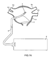
- FIG. 1A illustrates an exemplary system for treating tissue using a transducer assembly.
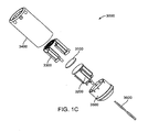
- FIGS. 1B-1C illustrate exemplary embodiments of a transducer assembly.
- FIGS. 2A - 2D illustrate alternative embodiments of the transducer element.
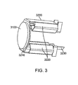
- FIG. 3 illustrates the transducer element with a first heat sink.
- FIG. 4 illustrates the transducer element with a second heat sink.
- FIG. 5 illustrates the transducer assembly in a tubular jacket.
- FIG. 6 illustrates an ablation pattern in tissue.
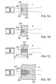
- FIGS. 7A - 7D illustrate the progression of ablation in tissue.
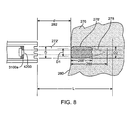
- FIG. 8 illustrates an alternative lesion shape
- FIG. 1A is a diagrammatic illustration of an exemplary embodiment of a system for creating ablation zones in human tissue, as described in the above referenced related parent applications.
- a catheter device C is housed within a sheath S.
- a proximal portion of the catheter C is coupled to a console P.
- a distal portion of the catheter C, comprising an ultrasonic transducer subassembly T, is introduced into the heart, preferably transseptally, into the left atrium (LA), adjacent the pulmonary veins PV of a patient.
- LA left atrium
- the transducer subassembly T is energized to provide ultrasonic energy for ablating tissue.
- the console P controls energy delivery to the transducer subassembly T, as well as movements of the distal portion of the catheter C to trace ablation paths. Additional details on the ablation system are disclosed in U.S. Provisional Patent Application No. 61/254,997 .
- transducer subassemblies are described herein with respect to one embodiment of a catheter for sensing and ablating tissue.
- the transducer assemblies of this invention may be utilized with any suitable device in both medical and non-medical fields.
- the transducer subassemblies comprise transducer elements and are configured such that the same transducer element may be used to both image (for example, in A-mode) and ablate.
- the transducer elements may be in the shape of a disc, or other shapes may be used for the transducer elements.
- the transducer subassemblies are also configured for effective cooling of the transducer elements, in order to increase the efficiency of transduction. This is accomplished by affixing (e.g. by bonding, welding, snap fitting, etc.) a distal and a proximal heat sink to the transducer element, thereby conducting heat away from the transducer element.
- the distal heat sink comprises an acoustically matching layer and the proximal heat sink comprises an acoustically mismatched backing layer.
- each of the heat sinks is configured to allow for a cooling substance (e.g., a fluid such as saline, water) to be directed to and dissipate the heat from the proximal and distal surfaces (hereinafter also referred to as "faces") of the transducer element.
- a cooling substance e.g., a fluid such as saline, water
- a transducer subassembly 3000 is placed at or near the distal portion of a catheter 2000 and contained within a tubular jacket 3400.
- the catheter 2000 may be any suitable catheter and comprises at least one lumen 2100.
- the components of transducer subassembly 3000 are shown in an assembled view in FIG. 1B , and in an exploded view in FIG. 1C .
- the transducer subassembly 3000 comprises a transducer element 3100 having a distal face 3102 and a proximal face 3104.
- the transducer subassembly 3000 further comprises heat sinks that serve to cool the transducer element 3000 by conducting heat away from it.
- the transducer subassembly 3000 comprises a distal heat sink 3300 bonded to the distal face 3102 of the transducer element 3100, and a proximal heat sink 3200 bonded to the proximal face 3104 of the transducer element 3100.
- the heat sinks are further configured to increase the operating efficiency of the transducer element 3000 through acoustic matching and acoustic reflection.
- the distal heat sink 3300 comprises an acoustically matching layer portion, i.e., a portion whose composition and thickness provides a 1 ⁇ 4 wavelength matching layer between the transducer element 3100 and any fluid in front of the transducer subassembly 3000.
- the proximal heat sink 3200 comprises an acoustically mismatched layer portion, i.e., a portion whose composition is acoustically mismatched to the acoustic impedance of the transducer element 3100, thereby reflecting ultrasound waves emanating from the transducer element 3100 back towards the transducer element 3100.
- acoustically mismatched layer portion i.e., a portion whose composition is acoustically mismatched to the acoustic impedance of the transducer element 3100, thereby reflecting ultrasound waves emanating from the transducer element 3100 back towards the transducer element 3100.
- the transducer subassembly 3000 also comprises a base 3500 anchoring the heat sinks 3200 and 3300, with the transducer element 3100 bonded between the heat sinks.
- the transducer subassembly 3000 is powered using one or more electrical cables 3600 bonded to each of the heat sinks 3200 and 3300. These electrical cables 3600 are exemplarily provided through a pair of twisted wires, as shown in FIGS. 1B and 1C . As will be appreciated, they could also be coaxial or separate untwisted wires.
- the heat sinks 3200 and 3300 comprise electrical attachments (not shown) for electrically coupling the heat sinks 3200 and 3300 to the electrical cables 3600, thereby providing electrical power to the transducer element 3100.
- the transducer element 3100 comprises electrode platings on the distal and proximal faces in order to distribute the electrical energy over the faces of the transducer element 3100.
- the transducer element 3100 comprises a single transducer element.
- the transducer is of a suitable size to fit into a catheter configured to be introduced percutaneously into the atria of the heart.
- the transducer diameter is less than 0.2 inches, and preferably less than 0.15 inches.
- the transducer element may comprise a variety of geometries, as well as a variety of acoustically active and inactive portions. Such transducer element properties in turn influence the transducer's imaging and ablative properties, such as the shape of the created ablation lesions.
- the transducer element 3100 is a flat, circular disc that transmits ultrasound energy from its proximal and distal faces.
- the transducer element 3100 may alternatively have more complex geometry, such as either concave or convex, to achieve an effect of a lens or to assist in apodization (i.e., in selectively decreasing the vibration of a portion or portions of the surfaces of the transducer element 3100) and management of the propagation of the ultrasound beam.
- the transducers 3100a and 3100b include at least one acoustically inactive portion 4200, with the remainder of the transducer surface comprising an acoustically active portion.
- the acoustically inactive portion 4200 does not emit an energy beam when the transducer is energized, or may alternatively emit an energy beam with a very low (substantially zero) energy.
- the acoustically inactive portion 4200 has several functions.
- the shape of a lesion produced by ablating tissue using such a transducer may correspond with the shape of the acoustically active ablating portions.
- the shape of the lesion will be tear-drop shaped.
- the shape of the lesion will be approximately tooth-shaped or a blunted tear-shaped. This is because the acoustically inactive portion 4200 in FIG. 2A will preclude prolonged ablation at the corresponding central portion of the tissue. Since prolonged ablation of tissue creates a deeper ablation, the presence of acoustically inactive portion 4200 precludes ablation from reaching further into the tissue at the central portion.
- the lesion thus is approximately tooth-shaped or blunted tear-shaped, as illustrated by the exemplary lesion shape L of FIG. 2A , rather than tear-shaped.
- acoustically inactive portion 4200 in any of the embodiments shown, further functions to aid in the temperature regulation of the transducer elements 3100a and 3100b, i.e., in preventing the transducer elements from becoming too hot.
- an acoustically inactive portion 4200 is a hole or gap defined by the boundary of the acoustically active region of the transducer element.
- an optional coolant source may be coupled to (or in the case of a coolant fluid, it may flow through) the hole or gap defined by the transducer element to further cool and regulate the temperature of the transducer element.
- the acoustically inactive portion 4200 may comprise a material composition with different properties from that of the active region of the transducer element.
- the acoustically inactive material may be made of a metal, such as copper, which further functions to draw or conduct heat away from the transducer element.
- the acoustically inactive portion 4200 may be made from the same material as the transducer element, but with the electrode plating removed or disconnected from the electrical attachments.
- the acoustically inactive portion 4200 may be disposed along the full thickness of the transducer element, or may alternatively be a layer of material on or within the transducer element that has a thickness less than the full thickness of the transducer element.
- the transducer element 3100a is a doughnut-shaped transducer that comprises a hole (or acoustically inactive portion) 4200 in the center portion of the otherwise circular disc-shaped transducer element.
- the transducer element 3100a of this embodiment has a circular geometry, but may alternatively be elliptical, polygonal as shown in FIG. 2B , or any other suitable shape.
- the transducer element 3100a includes a singular, circular acoustically inactive portion 4200, but may alternatively include any suitable number of acoustically inactive portions 4200 of any suitable geometry, as shown in FIG. 2B .
- Exemplary geometries of acoustically inactive portions include circular, square, rectangular, elliptical, polygon, or any other shaped region.
- the total energy emitted from the transducer element is related to the acoustically active surface area of the transducer element. Therefore, the size and location of acoustically inactive portion(s) 4200 may sufficiently reduce the heat build-up in the transducer element, while allowing the transducer element to provide as much output energy as possible or as desired.
- the transducer elements may optionally be configured to operate at more than one frequency. This allows them to be used for multi-frequency ablating or for contemporaneous ablation and diagnosis.
- a multi-frequency transducer element may be operated intermittently at a first power level using a first frequency range that is used to image a portion of the tissue in order to identify a target tissue, and operated at a second power level using a second frequency range that is used to ablate the target tissue.
- the imaging frequency is in the range of about 5 MHz to 30 MHz
- the ablation frequency is preferably in the range of 5 to 25 MHz, more preferably in the range 8 to 20 MHz, and even more preferably in the range 10 to 18 MHz.
- the transducers achieving these configurations are shown to exemplarily be annular transducers or grid arrays.
- the transducer elements 3100c and 3100d are configured to be capable of transmitting at more than one frequency.
- the transducer element 3100c includes a plurality of annular transducer portions 4400.
- the plurality of annular transducer portions is a plurality of concentric rings, but may alternatively have any suitable configuration with any suitable geometry, such as elliptical or polygonal.
- the transducer element 3100c includes one or more acoustically inactive portions 4200, such as the center portion of the transducer 3100c.
- the plurality of annular transducer portions 4400 includes at least a first annular portion and a second annular portion.
- the first annular portion may have material properties that differ from those of the second annular portion, such that the first annular portion emits a first energy beam that is different from a second energy beam emitted by the second annular portion.
- the first annular portion may be energized with a different frequency, voltage, duty cycle, power, and/or for a different length of time from the second annular portion.
- the first annular portion may be operated in a different mode from the second annular portion.
- the first annular portion may be operated in a therapy mode, such as ablation mode, which delivers a pulse of ultrasound energy sufficient for heating the tissue.
- the second annular portion may be operated in an imaging mode, such as A-mode, which delivers a pulse of ultrasound of short duration, which is generally not sufficient for heating of the tissue but functions to detect characteristics of the target tissue and/or environment in and around the ultrasound delivery system.
- A-mode an imaging mode
- the first annular portion may further include a separate electrical attachment from that of the second annular portion.
- the transducer element 3100d includes a grid of transducer portions 4600.
- the grid of transducer portions 4600 has any suitable geometry such as circular, rectangular, elliptical, polygonal, or any other suitable geometry.
- the transducer element 3100d in this variation may further include one or more transducer portions that are acoustically inactive.
- the grid of transducer portions 4600 includes at least a first transducer portion and a second transducer portion. The first transducer portion and the second transducer portion are portions of a single transducer with a single set of material properties.
- the first transducer portion is energized with a different frequency, voltage, duty cycle, power, and/or for a different length of time from the second transducer portion. Furthermore, the first transducer portion may be operated in a different mode from the second transducer portion. For example, similar to the description above, the first transducer portion may operate in a therapy mode, such as ablate mode, while the second transducer portion may operate in a imaging mode, such as A-mode.
- the first transducer portion may further include a separate electrical attachment from that of the second transducer portion. For example, the first transducer portion may be located towards the center of the transducer element 3100d and the second transducer portion may be located towards the outer portion of the transducer element 3100d.
- the second transducer portion may be energized while the first transducer portion remains inactive.
- the first transducer portion has material properties that differ from those of the second transducer portion, such that the first transducer portion emits a first energy beam that is different from a second energy beam emitted from the second transducer portion.
- the first transducer portion may also be energized with a different frequency, voltage, duty cycle, power, and/or for a different length of time from the second transducer portion.
- FIG. 3 shows the proximal heat sink 3200.
- the proximal heat sink 3200 comprises a bonding portion 3210 and a substantially bent portion forming legs 3220 that are generally orthogonal to the bonding portion 3210.
- the proximal heat sink further comprises at least one electrical attachment 3230.
- the distal heat sink comprises an electrical attachment 3330 (shown in Fig. 4 ).
- the electrical wires 3600 are connected to the electrical attachments 3230 and 3330.
- the disclosed arrangement eliminates "hot spots" and results in a uniform electrical power density across the surface of the crystal. Additionally, this results in an easier assembly or manufacturing process.
- the bonding portion 3210 is bonded to the proximal face of the transducer element 3100 with a suitable bonding material such as an epoxy to form a bond layer. Though shown as substantially flat in this embodiment, one skilled in the art will appreciate that the bonding portion 3210 may be any suitable configuration such as a concave portion to still maintain the functionality described herein.
- the substantially bent portion 3220 comprises legs, or elements that protrude proximally from the transducer element 3100. Further, the bent portion 3220 is configured in a manner to allow for fluid to flow through the bent portion and also allows the fluid to surround and cool the proximal face of the transducer element 3100. The fluid that could be accommodated within the bent portion could be any suitable fluid that.
- the proximal heat sink 3200 is formed from a suitable material such as copper of a suitable thickness.
- the thickness of the material for this heat sink preferably ranges between 0.0001 inches to 0.01 inches for a copper heat sink.
- Proximal heat sink 3200 serves to cool the proximal face of the transducer by conducting and dissipating the heat away from the transducer element 3100. Heat from the transducer element 3100 is absorbed by the bonding portion 3210, and conducted to the bent portion 3220 where it is dissipated into the circulating fluid. This dissipation provides some cooling to the proximal face of the transducer element 3100. Additionally, the bent portion 3220 is configured in a manner to allow for fluid to surround and cool the proximal face of the transducer element 3100. For example, as shown in FIG.
- the bent portion 3220 provides for one or more pockets behind the transducer element 3100 where a fluid may be introduced to flow and cool both the transducer element 3100 as well as the proximal heat sink 3200 that has dissipated heat from the proximal face of the transducer element 3100.
- the proximal heat sink 3200 also serves as a heat spreader to reduce hot spots in the transducer element 3100, and thereby preserve it over its entire face. Without this heat spreading, the center of the transducer element 3100 would be substantially hotter than the rest of the transducer element 3100.
- the bonding portion 3210 can be configured to maximize the amount of reflected energy transmitted from the transducer element 3100. Since many metals suitable for heat sink applications have acoustic impedances that are not too dissimilar from PZT, the boundary between PZT and the heat sink itself does not provide a very effective reflective interface. However, another material immediately proximal to the heat shield could be selected so that it provides an efficient acoustic reflector. For example, air provides an excellent acoustic mismatch, as does water, and therefore acts as good reflectors. Water is preferred since it also acts as a thermal conductor, even though it is not quite as effective a reflector as air. Air could be used, provided that it does not interfere with the flow of cooling fluid around the transducer assembly.
- the bonding portion of 3210 could be constructed from two metal layers capturing a third thin layer of air in between.
- a backing material may be located proximal to the proximal heat sink 3200 to provide an acoustically absorptive medium to minimize reverberations to further optimize imaging performance.
- Such backing materials may optionally be made of combinations of epoxy, metal particles, tungsten and the like.
- the transducer element 3100 or the transducer subassembly 3000 may be placed on a tripod-style structure (not shown) such that the proximal surface of the transducer element 3100 faces into the tripod.
- a pocket forms in the space between the transducer element 3100 and the tripod base.
- This pocket serves as an alternative backing with the same two-fold purpose. First, it is acoustically mismatched and thereby reflective of the ultrasound waves emanating from the transducer element 3100. Second, as fluid (for example saline or water) is introduced into the transducer assembly 3000, the pocket also allows for the fluid to come into contact with the transducer element 3100 and thereby provide for additional cooling.
- fluid for example saline or water
- acoustically mismatched material with reasonable thermal conduction could be used in place of fluid.
- materials include metal with trapped air, for example steel wool or porous metal with entrapped air.
- the rear of the PZT may comprise a thin heat spreader comprising the entire rear face with a pocket of porous metal attached behind.
- the center of the PZT could be further cooled by providing a thermally conducting center post as part of the heat sink, allowing an annular ring of air to be trapped behind the bonding portion 3210.
- a distal heat sink 3300 (which also serves as a heat spreader) for distributing the heat and cooling the distal face of the transducer element 3100.
- the distal heat sink 3300 also comprises a bonding portion 3310 and a substantially bent portion 3320 that is orthogonal to the flat portion 3310.
- the distal heat sink further comprises at least one electrical attachment 3330.
- the distal heat sink 3300 is configured such that the bonding portion 3310 is bonded to the distal face of the transducer element 3100.
- the substantially bent portion 3320 comprises elements or legs that protrude proximally from the transducer element 3100.
- the bonding portion 3310 is further configured to serve as an acoustically matching layer for the transducer element 3100.
- the bonding portion 3310 is made of a suitable material such as aluminum; other such suitable materials include graphite, metal-filled graphite or ceramic, or an amalgam of graphite and copper or tungsten, in suitable thickness that range from .026 inches to 0.00026 inches so that it is 1 ⁇ 4 wavelength at the desired frequency.
- the bonding portion 3310 is bonded to the distal face of the transducer element 3100 with a suitable bonding material such as an epoxy to form a bond layer.
- the bonding portion 3310 comprises perforations or holes 3315 that may be filled with epoxy applied in a layer of a suitable thinness to enhance the acoustic impedance matching.
- Perforations in the distal matching layer can be accomplished in many ways.
- the perforated structure is made of a combination of metal matrix containing open spaces, later to be filled with an epoxy material.
- the metal matrix can be a wire grid.
- the perforated structure may be a matrix of epoxy film, and the holes may be filled with a metal such as aluminum.
- the ratio of epoxy to the metal mixture is configured to enhance acoustic impedance matching.
- the acoustic impedance is determined by the acoustic impedance of the two composite materials, and the ratio of the mixture. For example, using aluminum and EPO-TEK® 377 (Epoxy Technology, Inc., Billerica, MA) the appropriate ratio is 35-60 % volume fraction of epoxy and a good acoustic impedance matching is achieved at a 40-50% volume fraction of epoxy and an ideal match about 41 %. Additionally, the perforations or holes 3315 have a sufficiently small diameter as compared to the wavelength of the ultrasonic beam, thereby allowing the bonding portion 3310 to appear homogeneous to the propagating waves emanating from the transducer element 3100.
- the bonding portion 3210 at proximal surface of the transducer crystal also may benefit from using perforations or holes in the material used to achieve acoustic impedance mismatch.
- Such materials may include copper, tungsten and the like.
- an epoxy layer with metal particles sprinkled in it and a distribution of holes or perforations may achieve the same purpose of providing acoustic impedance mismatch.
- both non-conductive and conductive epoxy could be used to form either the proximal or distal bond layer.
- the epoxy is exemplarily a non-conductive epoxy of a low viscosity (e.g., EPO-TEK® 377).
- the epoxy is applied in a layer of suitable thinness to minimize its impact on acoustic impedance matching, while maximizing thermal conduction to cool the transducer 3100.
- the bond layers are also configured to electrically connect the heat sinks 3310 and 3210 to the transducer 3100. This is successfully accomplished without the use of conductive epoxy by configuring the transducer 3100 faces and the bonding portions 3310 and 3210 to be rough.
- each bond layer is of sufficient thinness to allow the surface roughness of the transducer 3100 to electrically contact the surface roughness of the heat sinks 3310 and 3210. This allows the rough surfaces of the transducer element 3100 to come into direct electrical contact with their relevant heat sinks, thereby obviating the need for using electrically conductive epoxy (which may degrade with heat). Thus, electrical conduction occurs via the contact points between the rough surfaces of the transducer element 3100 and the heat sinks, rather than through the epoxy.
- parylene or any such suitable coating is disposed on the bonding portion 3310 of the distal heat sink 3300 to act as an additional matching layer.
- One result of the coating may be to thus produce a second acoustic matching layer for increased efficiency of transducer element 3100 conduction and to further optimize the wide bandwidth performance.
- the thickness of this parylene coat is % of the target ultrasound wavelength.
- both heat sinks 3200 and 3300 are coated with parylene or any such suitable coatings to provide electrical isolation. Further, heat sinks are anodized to provide electrical isolation while maximizing thermal conduction.
- the transducer subassembly 3000 is located within a tubular jacket 3400, as shown in FIG. 5 .
- the tubular jacket 3400 is a hollow cylinder with a proximal and distal end.
- the transducer subassembly 3000 is placed into the tubular jacket 3400 such that the distal end of the tubular jacket protrudes a suitable distance, for example between 1mm to 5mm beyond the distal end of the transducer subassembly 3000.
- the distal end of the tubular jacket 3400 comprises a distal opening 3410, and fluid exit ports 3420 located near the distal opening. Cooling of the transducer element 3100 may be accomplished by introducing a cooling fluid or gel, such as saline, water, or any physiologically compatible fluid or gel, into the proximal end of the tubular jacket 3400.
- the cooling fluid has a lower temperature relative to the temperature of the transducer element 3100.
- the cooling fluid flows along the bent portions 3220 and 3320 of heat sinks 3200 and 3300 and over both bonding portions 3210 and 3310 and exits through the distal opening 3410, the fluid exit ports 3420, or any combination thereof.
- the exit ports 3420 may be in the form of a grating, a screen, holes, drip holes, a weeping structure, or any of a number of suitable apertures.
- any or all of the metal components described in transducer subassembly 3000 are provided with a plating of a suitable biocompatible material such as gold. Such plating is provided to the individual components before the transducer assembly is assembled.
- the temperature of the cooling fluid or gel is sufficiently low that it cools the transducer element 3100 and, optionally, the target tissue.
- the temperature of the fluid or gel is between approximately -5 and body temperature.
- the temperature of the cooling fluid or gel is within a temperature range such that it cools the transducer element 3100, but does not cool the target tissue, and may actually warm the target tissue.
- the fluid or gel may alternatively be any suitable temperature, including room temperature, to sufficiently cool the transducer element 3100.
- the invention described above has the advantage of keeping the smaller transducer assembly cool.
- the transducer diameter is small enough (less than 0.2 inches, and ideally less than 0.15 inches) to fit into the tip of a catheter and yet generate power density levels that are high enough to create tissue lesions (about 50 watts/cm 2 to 2500 watts/cm 2 ).
- This invention keeps the transducer assembly cool in order to create tissue lesions efficiently.
- the interaction of the ultrasound beam with the tissue is shown in FIG. 6 .
- the tissue 276 is presented to the ultrasound beam 272 within a collimated length L.
- the front surface 280 of the tissue 276 is at a distance d (282) away from the distal tip 2110 of the catheter 2000.
- d 282
- thermal energy heats the tissue to temperatures higher than the surrounding tissue.
- the result is a heated zone 278 which has a typical shape of an elongated tear drop.
- the diameter D1 of the zone 278 is smaller than the transducer aperture diameter D at the tissue surface 280, and further, the outer layer(s) of tissue 276 remain substantially undamaged. This is due to the thermal cooling provided by the surrounding fluid which is flowing past the tissue surface 280. More or less of the outer layers of tissue 276 may be spared or may remain substantially undamaged, depending on the amount that the tissue surface 280 is cooled and/or depending on the characteristics of the ultrasound delivery system (including the transducer element 3100 the ultrasound beam 272, the ultrasound energy and the frequency).
- the energy deposited in the ablation zone 278 interacts with the tissue such that the endocardial surface remains pristine and/or not charred.
- the ablation zone 278 has a larger diameter D2 than D1, as determined by the heat transfer characteristics of the surrounding tissue as well as the continued input of the ultrasound energy from the beam 272.
- the ultrasound energy is being absorbed by the tissue 276, and less of it is available to travel further into the tissue.
- a correspondingly smaller diameter heated zone is developed in the tissue 276, and the overall result is the formation of the heated ablation zone 278 which is in the shape of an elongated tear drop limited to a depth 288 into the tissue 276.
- the formation of the ablation zone (including the size of the ablation zone and other characteristics) is dependent on time, as shown in FIGS. 7A - 7D , which show the formation of the lesion at times t1, t2, t3 and t4, respectively.
- FIGS. 7A - 7D show the formation of the lesion at times t1, t2, t3 and t4, respectively.
- the ablation lesion 278 grows slightly in diameter and length, and then stops growing due to the steady state achieved in the energy transfer from its ultrasound form to the thermal form balanced by the dissipation of the thermal energy into the surrounding tissue.
- the example shown in of FIG. 7D shows the lesion after an exposure t4 of approximately 30 seconds to the ultrasound beam 272.
- the lesion reaches a natural limit in size and does not grow indefinitely.
- the shape of the lesion or ablation zone 278 formed by the ultrasound beam 272 depends on factors such as the ultrasound beam 272, the transducer element 3100 (including the material, the geometry, the portions of the transducer element 3100 that are energized and/or not energized, etc.), any matching layers and/or backings present, the electrical signal from the source of electrical energy (including the frequency, the voltage, the duty cycle, the length and shape of the signal, etc.), and the duration of energy delivery.
- the characteristics of the target tissue include the thermal transfer properties and the ultrasound absorption, attenuation, and backscatter properties of the target tissue and surrounding tissue.
- the size and characteristics of the ablation zone 278 also depend on the frequency and voltage applied to the transducer element 3100 to create the desired ultrasound beam.
- the particular example lesion shown in FIGS. 7A through 7D is a tear-shaped lesion, for example as produced by a transducer element 3100 comprising a circular disc.
- a second variation of ablation shape is shown in FIG. 8 , where the ablation zone 278' has a shorter depth 288'. In this variation, the lesion 278' has a more blunt shape than the ablation zone 278 of FIG. 6 .
- One possible lesion geometry of this second variation may be a tooth-shaped geometry, as shown in FIG. 8 , though the geometry may alternatively have a blunted tear shape, a circular shape, or an elliptical shape.
- zone 278' (similarly to zone 278 in FIG. 6 ) has a diameter D1 smaller than the diameter D of the beam 272' at the tissue surface 280 due to the thermal cooling provided by the surrounding fluid flowing past the tissue surface 280.
- This variation in lesion geometry is produced by a transducer 31 00a having an acoustically inactive portion 4200 located at its center, i.e., a doughnut-shaped transducer which emits an ultrasound beam 272' that is generally more diffused, with a broader, flatter profile, than the ultrasound beam 272 shown in FIG. 6 .
- the ultrasound beam 272' emitted from such a doughnut-shaped transducer, as shown in FIG.
- the ultrasound energy density determines the speed at which the ablation occurs.
- the acoustic power delivered by the transducer element 3100 divided by the cross sectional area of the beamwidth, determines the energy density per unit time.
- effective acoustic power ranges preferably from 0.5 to 25 watts, more preferably from 2 to 10 watts, and even more preferably from 2 to 7 watts.
- the corresponding power densities range from approximately 50 watts/cm 2 to 2500 watts/cm 2 ). These power densities are developed in the ablation zone. As the beam diverges beyond the ablation zone, the energy density falls such that ablation will not occur, regardless of exposure time.
- the transducer subassembly 3000 may additionally be coupled to a sensor (not shown).
- a sensor is a temperature sensor.
- the temperature sensor functions to detect the temperature of the surrounding environment, the transducer element 3100, and/or the temperature of any other suitable element or area.
- the sensor may also be used to monitor temperature of cooling fluid as it flows past the transducer.
- the temperature sensor is a thermocouple, but may alternatively be any suitable temperature sensor, such as a thermistor or an infrared temperature sensor.
- the temperature sensor is coupled to the transducer, for example, on the proximal face.
- Temperature information gathered by the sensor is used to manage the delivery of continuous ablation energy to the tissue 276 during therapy, as well as to manage the temperature of the target tissue and/or the ultrasound delivery system.
- the sensor has a geometry that is substantially identical to the geometry of the transducer element 3100, so that the area diagnosed by the sensor is substantially identical to the area to be treated by the transducer element 3100.
- the sensor has a smaller geometry to minimize interfering with the delivery of ultrasound energy, but may be located in a region that is a local hot spot.
- a small thermocouple mounted in the center of the proximal heat spreader 3200 monitors the temperature at the hottest spot of the transducer assembly. Additional details on temperature sensors are disclosed in applications cited herein.
- the same ultrasound transducer element 3100 serves as a sensor and is used for the purpose of tissue detection.
- the transducer element 3100 in order to achieve ablation, is used to generate and deliver an ultrasound beam of sufficient energy to the tissue in a manner such that the energy input exceeds the thermal relaxation provided by the cooling due to the surrounding tissue.
- This mode of energizing the ultrasound transducer element 3100 is termed as the ablation mode.
- the transducer element 3100 may be used to image tissue or to detect tissue characteristics, by utilizing an ultrasound signal optimized for tissue sensing which is generally not sufficient for heating of the tissue.
- A-Mode or Amplitude Mode imaging.
- This mode of energizing the transducer element 3100 is termed as the imaging mode.
- the imaging mode is utilized in directing the therapy provided by the ablation of the tissue.
- the transducer element 3100 can be used in the imaging mode in order to detect the gap (namely, the distance of the tissue surface from the distal tip of the catheter 2000), the thickness of the tissue targeted for ablation, characteristics of the ablated tissue, the incident beam angle, or any other suitable parameter or characteristic of the tissue and/or the environment around the ultrasound delivery system, such as temperature, thickness and ablation depth.
- the ultrasound delivery system of the preferred embodiments includes a processor, coupled to the sensor, that controls the electrical attachments and/or the electrical signal delivered to the electrical attachments, based on the information obtained by the sensor.
- the processor may be a conventional processor, or it may alternatively be any suitable device to perform the desired processing functions.
- the processor receives information from the sensor, such as information related to the distance between the catheter and the tissue (i.e., the gap distance), the thickness of the tissue targeted for ablation, the characteristics of the ablated tissue, or any other suitable parameter or characteristic. Based on this information, the processor controls the ultrasound beam emitted by the transducer element 3100 by modifying the electrical signal sent to the transducer element 3100 via the electrical attachment. This may include modifying the frequency, the voltage, the duty cycle, the length of the pulse, and/or any other suitable parameter. The processor may also control the ultrasound beam in multi-element transducers by controlling which portions of the transducer element are energized, and/or by controlling the frequency, voltage, duty cycle, etc. at which various portions of the transducer element may be energized.
- the processor may further be coupled to a fluid flow controller.
- the processor may control the fluid flow controller in order to increase or decrease fluid flow based on the detected characteristics of the ablated tissue, of the unablated or target tissue, the temperature of the cooling fluid, tissue and/or energy source, and/or any other suitable conditions. Further, the processor may control the fluid flow controller in order to maintain the transducer element 3100 within a desired operating range of temperatures. Further, the motion of the transducer to create a lesion line or shape in the tissue may be controlled either by an operator or via one or more motors under processor control.
- the shape of the ablation zone 278 can be controlled.
- the depth 288 of the ablation zone can be controlled such that a transmural or substantially transmural lesion is achieved.
- the nature of the lesion can be controlled by controlling the speed of the beam. The speed at which the beam moves along the tissue determines the amount of energy deposited in the tissue. Thus, for example, slower speeds result in longer dwell times, thereby increasing the energy transferred to the tissue and, hence, creating deeper lesions.
- the processor functions to minimize the possibility of creating a lesion beyond the targeted tissue, for example, beyond the outer atrial wall.
- the processor turns off the power generator and/or ceases to send electrical signals to the transducer and/or moves the beam.
- the processor may function to maintain a preferred gap distance between the transducer and the surface of the target tissue.
- the gap distance is preferably between 2 mm and 25 mm, more preferably between 2 mm and 20 mm, and even more preferably between 2 mm and 15 mm.
- the processor may reposition the energy delivery system. For example, as the catheter 2000 is rotated, the ablation window sweeps an ablation path (such as a circular or elliptical ablation path) creating a section of a conical shell.
- the processor may move the elongate member forwards or backwards along the Z-axis, or indicate that it should be moved, in order to adjust for possible variations in anatomy.
- the operator can reposition the catheter 2000, or the processor may be coupled to a motor drive unit or other control unit that functions to position the catheter 2000.
- transducer elements and transducer subassemblies have been described in the context of ablation catheters, it should be understood that the transducer elements and transducer subassemblies described herein can be used as part of any device configured to ultrasonically image and/or ablate tissue. Additionally, while the above is a complete description of the preferred embodiments of the invention, various alternatives, modifications, and equivalents may be used. Therefore, the above description should not be taken as limiting the scope of the invention which is defined by the appended claims.
Abstract
Description
- 1. Field of the Invention. The present application generally relates to systems for creating ablation zones in human tissue. More specifically, the present application relates to transducer configurations used to create tissue lesions, and even more specifically to ultrasound transducers used to treat fibrillation of the heart. While the present application emphasizes treatment of atrial fibrillation, one of skill in the art will appreciate that this it not intended to be limiting, and that the systems disclosed herein may also be used to treat other arrhythmias as well as to treating other conditions by creating lesions in tissue.
- The condition of atrial fibrillation (AF) is characterized by the abnormal (usually very rapid) beating of the left atrium of the heart which is out of synch with the normal synchronous movement ('normal sinus rhythm') of the heart muscle. In normal sinus rhythm, the electrical impulses originate in the sino-atrial node ('SA node') which resides in the right atrium. The abnormal beating of the atrial heart muscle is known as 'fibrillation' and is caused by electrical impulses originating instead at points other than the SA node, for example, in the pulmonary veins (PV).
- There are pharmacological treatments for this condition with varying degree of success. In addition, there are surgical interventions aimed at removing the aberrant electrical pathways from PV to the left atrium ('LA') such as the 'Cox-Maze III Procedure'. This procedure has been shown to be 99% effective but requires special surgical skills and is time consuming. Thus, there has been considerable effort to copy the Cox-Maze procedure using a less invasive percutaneous catheter-based approach. Less invasive treatments have been developed which involve use of some form of energy to ablate (or kill) the tissue surrounding the aberrant focal point where the abnormal signals originate in PV. The most common methodology is the use of radio-frequency ('RF') electrical energy to heat the muscle tissue and thereby ablate it. The aberrant electrical impulses are then prevented from traveling from PV to the atrium (achieving the 'conduction block') and thus avoiding the fibrillation of the atrial muscle. Other energy sources, such as microwave, laser, and ultrasound have been utilized to achieve the conduction block. In addition, techniques such as cryoablation, administration of ethanol, and the like have also been used. Some of these methods and devices are described below.
- There has been considerable effort in developing catheter based systems for the treatment of AF using radiofrequency (RF) energy. One such method includes a catheter having distal and proximal electrodes at the catheter tip. The catheter can be bent in a coil shape, and positioned inside a pulmonary vein. The tissue of the inner wall of the PV is ablated in an attempt to kill the source of the aberrant heart activity.
- Another source used in ablation is microwave energy. One such intraoperative device consists of a probe with a malleable antenna which has the ability to ablate the atrial tissue.
- Still another catheter based method utilizes the cryogenic technique where the tissue of the atrium is frozen below a temperature of -60 degrees C. This results in killing of the tissue in the vicinity of the PV thereby eliminating the pathway for the aberrant signals causing the AF. Cryo-based techniques have also been a part of the partial Maze procedures described above. More recently, Dr. Cox and his group have used cryoprobes (cryo-Maze) to duplicate the essentials of the Cox-Maze III procedure.
- More recent approaches for the treatment of AF involve the use of ultrasound energy. The target tissue of the region surrounding the pulmonary vein is heated with ultrasound energy emitted by one or more ultrasound transducers. One such approach includes a catheter distal tip portion equipped with a balloon and containing an ultrasound element. The balloon serves as an anchoring means to secure the tip of the catheter in the pulmonary vein. The balloon portion of the catheter is positioned in the selected pulmonary vein and the balloon is inflated with a fluid which is transparent to ultrasound energy. The transducer emits the ultrasound energy which travels to the target tissue in or near the pulmonary vein and ablates it. The intended therapy is to destroy the electrical conduction path around a pulmonary vein and thereby restore the normal sinus rhythm. The therapy involves the creation of a multiplicity of lesions around individual pulmonary veins as required.
- Yet another catheter device using ultrasound energy includes a catheter having a tip with an array of ultrasound elements in a grid pattern for the purpose of creating a three dimensional image of the target tissue. An ablating ultrasound transducer is provided which is in the shape of a ring which encircles the imaging grid. The ablating transducer emits a ring of ultrasound energy at 10 MHz frequency.
- While such ablation therapies alone are promising, it is preferred that devices and systems combine these ablation therapies with imaging capabilities in a single unit. It would be particularly useful to provide sensing or imaging (often used interchangeably) of the treatment region to properly position the ablation device relative to the treatment region, as well as to evaluate progression of the treatment. Such imaging assists the system or the operator to ensure that only the targeted tissue region is ablated. Furthermore, in a moving target such as heart tissue, the original target identified by imaging, can move and thus non-target tissue may be inadvertently ablated. Hence, contemporaneous (or almost contemporaneous) imaging and ablation minimizes the risk of ablating non-target tissue. Thus, one unmet need using ultrasound techniques for tissue ablation is to provide a device capable of both imaging as well as ablation.
- Attaining this goal involves redesigning the key components of a conventional ultrasound ablation system to also provide an imaging function. Typically, ultrasound ablation is accomplished using a transducer assembly. The transducer assembly comprises a transducer element, commonly one or more piezoelectrically active elements such as lead zirconate titanate (PZT) crystals. The PZT crystals often include an acoustical (impedance) matching layer on the ablating face to facilitate efficient power transmission and to improve the imaging performance. Further, the crystals may be bonded to a backing on the non-ablative face to reflect or absorb any ultrasound beams in the appropriate direction. The conventional acoustic transducers which are typically employed for the therapeutic purposes are acoustically large, often single-crystal devices having a narrower bandwidth in the frequency domain than is required for good imaging performance. Although they are designed to efficiently transmit acoustic energy to the target tissue, crystal devices with narrow bandwidth have previously been viewed as unsuited for imaging. This has been due to the perceived inability of conventional ablation transducers to handle the bandwidth of the ultrasound frequencies that would be optimized for both imaging and ablation. While ablation can be achieved using a narrower range of frequencies, imaging is usually performed using a wide range of frequencies. Thus, it is desirable that the PZT be able to accommodate a wider bandwidth than used for ablation in order to accommodate the imaging bandwidth.
- Wider transducer bandwidths are often achieved through the use of matching layers. Matching layers typically use materials with acoustic impedance between the acoustic impedances of the PZT and the tissue, and with a thickness approaching ¼ wavelength of the ultrasound frequency utilized. While matching layers are often used to improve the transmission of ultrasound from the PZT into the tissue, they also can be used to dampen the mechanical response of the PZT and broaden its bandwidth. This dampening can result in some reduction of transducer efficiency. Furthermore wide bandwidth transducers may be unable operate at high power levels because they cannot be cooled effectively, partly due to the thermally insulating properties of the matching layer. A conventional PZT transducer with a higher bandwidth may often be only 30% - 50% efficient in converting the electrical energy to acoustic energy, and much of the energy is converted to heat and lost in the transducer assembly. In addition to the lack of efficiency in converting to ultrasound energy, the heat further reduces the PZT efficiency and may cause the PZT crystal to depole and stop functioning as a transducer.
- Thus, an additional challenge is to cool the transducer to maintain a lower operating temperature than is presently provided for in commercially available systems. A cooled transducer can be driven harder, i.e., it can tolerate higher electric powers and produce higher acoustic powers. This higher acoustic output is useful in increasing the lesion size and/or reducing the amount of time required to create a lesion. Both of these attributes are important in the clinical application of treating AF.
- One method of cooling the transducer is to take advantage of the power density and heat dissipation that are dependent on the size of the transducer. As the diameter (and corresponding surface area) of the transducer increases, the power density drops, and the heat dissipation per unit surface area also drops. If large enough, conventional cooling methods may suffice to keep the transducer cool. However, in a catheter suitable for ablation using an interventional approach, the transducer must necessarily be small and yet also be able to generate the power density levels required to ablate tissue. In such a transducer, size is not a suitable method of regulating the transducer's temperature. Thus, due to the small transducer size and consequent high power densities and low heat dissipation, alternative approaches are warranted for cooling the transducer.
- One potential solution is the use of fluids to cool the transducer. Commonly, bodily fluids, such as blood flowing around the transducer, are used as a cooling fluid. However, blood tends to denature and collect around the transducer when heated. In addition to the attendant problems of possibly creating a clot in the atrium, the denatured blood may also adhere to the face of the transducer and create a layer of insulation, thereby further decreasing the performance of the transducer. In contrast, introduced (non-bodily) fluids such as saline or water do not have the same attendant problems as blood and are useful in maintaining lower transducer operating temperatures. However, in order to be effective, these introduced fluids have to be effectively transported to the entire transducer to cool all the faces of the transducer. If fluid transport is inadequate, the uncooled regions may develop "hot spots" that can impede the efficiency of the transducer.
- While some devices, such as single crystal ultrasound therapy systems have been reported for both imaging and therapeutic purposes, none disclose a method for cooling the entire transducer. Other multi-crystal transducer assemblies are also available that circumvent the concerns of the single-crystal model. Some of these systems provide a method for cooling the back of the transducer crystals. However, none of these systems or methods include cooling of the entire transducer crystal. As mentioned above, it is important to cool all the faces of the transducer (front and the back). Cooling only part of the transducer may lead to "hot spots" on some areas of the transducer, thereby decreasing the efficiency of the transducer in a situation where both ablation and imaging are necessary.
- To realize combined imaging and ablation capabilities, some systems have separate imaging and ablation units. For example one commercially available system includes a treatment and imaging system. This system comprises a probe with an ultrasound transducer adapted to obtain imaging information from a patient treatment region, and also a separate arm member to deliver ultrasonic energy to the treatment region. Naturally, these are bulky and not well suited for use in catheter based systems. A variant of the combined imaging and ablation units is using separate transducer elements for imaging and ablation. This approach suffers from many shortcomings including functionally, the ablated tissue is not identical to the imaged tissue, and structurally this configuration of discrete imaging and ablating elements occupies more space in a housing, where space is limited in a transducer assembly, especially when the transducer is at the tip of the catheter as used in an interventional approach. Additionally, a multi-element device is more expensive and inconvenient to manufacture, along with the complicated arrangements necessary for cooling the transducer elements. Further, multi-element devices are prone to misalignment, which may make them more difficult to use. Also, multi-element devices typically require more complex and expensive systems for their control and use.
- Thus, additional improvements are still desired in the field of ultrasound devices with combined imaging and ablating capabilities. In particular, it would be desirable to provide a device with a single-crystal transducer assembly where all faces of the transducer crystal are cooled to protect and preserve the operating efficiency. It would also be desirable to provide such a system that is easy to use, easy to manufacture and that is lower in cost than current commercial systems.
- 2. Description of Background Art. Patents related to the treatment of atrial fibrillation include, but are not limited to the following:
U.S. Patent Nos. 7,393,325 ;7,142,905 ;6,997,925 ;6,996,908 ;6,966,908 ;6,964,660 ;6,955,173 ;6,954,977 ;6,953,460 ;6,949,097 ;6,929,639 ;6,872,205 ;6,814,733 ;6,780,183 ;6,666,858 ;6,652,515 ;6,635,054 ;6,605,084 ;6,547,788 ;6,514,249 ;6,502,576 ;6,500,121 ;6,416,511 ;6,383,151 ;6,305,378 ;6,254,599 ;6,245,064 ;6,164,283 ;6,161,543 ;6,117,101 ;6,064,902 ;6,052,576 ;6,024,740 ;6,012,457 ;5,629,906 ;5,405,346 ;5,314,466 ;5,295,484 ;5,246,438 ;4,757,820 and4,641,649 . - Patent Publications related to the treatment of atrial fibrillation include, but are not limited to International
PCT Publication Nos. WO 2005/117734 ;WO 1999/002096 ; andU.S. Patent Publication Nos. 2005/0267453 ;2003/0050631 ;2003/0050630 ; and2002/0087151 . - Scientific publications related to the treatment of atrial fibrillation include, but are not limited to: Haissaguerre, M. et al., Spontaneous Initiation of Atrial Fibrillation by Ectopic Beats Originating in the Pulmonary Veins, New England J Med., Vol. 339:659-666; J. L. Cox et al., The Development of the Maze Procedure for the Treatment of Atrial Fibrillation, Seminars in Thoracic & Cardiovascular Surgery, 2000; 12: 2-14; J. L. Cox et al., Electrophysiologic Basis, Surgical Development, and Clinical Results of the Maze Procedure for Atrial Flutter and Atrial Fibrillation, Advances in Cardiac Surgery, 1995; 6: 1-67; J. L. Cox et al., Modification of the Maze Procedure for Atrial Flutter and Atrial Fibrillation. II, Surgical Technique of the Maze III Procedure, Journal of Thoracic & Cardiovascular Surgery, 1995;110:485-95; J. L. Cox, N. Ad, T. Palazzo, et al. Current Status of the Maze Procedure for the Treatment of Atrial Fibrillation, Seminars in Thoracic & Cardiovascular Surgery, 2000; 12: 15-19; M. Levinson, Endocardial Microwave Ablation: A New Surgical Approach for Atrial Fibrillation; The Heart Surgery Forum, 2006; Maessen et al., Beating Heart Surgical Treatment of Atrial Fibrillation with Microwave Ablation, Ann Thorac Surg 74: 1160-8, 2002; A. M. Gillinov, E. H. Blackstone and P. M. McCarthy, Atrial Fibrillation: Current Surgical Options and their Assessment, Annals of Thoracic Surgery 2002;74:2210-7; Sueda T., Nagata H., Orihashi K., et al., Efficacy of a Simple Left Atrial Procedure for Chronic Atrial Fibrillation in Mitral Valve Operations, Ann Thorac Surg 1997;63:1070-1075; Sueda T., Nagata H., Shikata H., et al.; Simple Left Atrial Procedure for Chronic Atrial Fibrillation Associated with Mitral Valve Disease, Ann Thorac Surg 1996;62:1796-1800; Nathan H., Eliakim M., The Junction Between the Left Atrium and the Pulmonary Veins, An Anatomic Study of Human Hearts, Circulation 1966;34:412-422; Cox J.L., Schuessler R.B., Boineau J.P., The Development of the Maze Procedure for the Treatment ofAtrial Fibrillation, Semin ; and Gentry et al., Integrated Catheter for 3-D Intracardiac Echocardiography and Ultrasound Ablation, IEEE Transactions on Ultrasonics, Ferroelectrics, and Frequency Control, Vol. 51, No. 7, pp 799-807.
- Further transducer assemblies are disclosed in
WO2006/034 000 A1 andUS2008/0262358 A1 . - The present invention is defined in the appended set of claims and discloses a transducer assembly with combined imaging and therapeutic capabilities that may be used to create lesions in tissue. In preferred embodiments, the transducer assembly is used to ablate tissue to create a conduction block in the target tissue which blocks aberrant electrical pathways. Thus, the transducer assembly may be used as a treatment for fibrillation or other arrhythmias, as well as other conditions requiring creation of a lesion in tissue.
- In a first aspect of the present invention, a transducer system comprises a transducer element comprising a proximal surface and a distal surface, and a first heat sink attached to the distal surface of the transducer element. The system also has a second heat sink attached to the proximal surface of the transducer element, and a base coupled to the first and second heat sinks. The base is configured to allow fluid flow past the transducer element for cooling of the proximal and distal surfaces of the transducer element, and the heat sinks.
- The system may further comprise a tubular jacket configured to house the base, the transducer element, and the first and second heat sinks. The tubular jacket may comprise at least one fluid exit port configured to allow fluid to exit the tubular jacket. The first heat sink may comprise a first bonding portion and a first substantially bent portion. The first bonding portion may be bonded to the distal surface of the transducer, and the first substantially bent portion may protrude proximally from the transducer element, thereby conducting heat away from the distal surface of the transducer element. The first bonding portion may comprise a material whose composition and dimension provides an acoustically matching layer on the distal surface of the transducer element. The first bonding portion may comprise a material chosen from the group consisting of aluminum, graphite, metal-filled graphite, ceramic, an amalgam of graphite and copper or tungsten, and an epoxy-filled metal. The bonding portion may be in electrical and/or thermal communication with the distal surface of the transducer element. Electrical communication between the bonding portion and the distal surface may be established by direct contact between the bonding portion and the distal surface. The direct contact may be controlled by surface roughness of the bonding portion and the distal surface.
- The second heat sink may comprise a second bonding portion and a second substantially bent portion. The second bonding portion may be bonded to the proximal surface of the transducer, and the second substantially bent portion may protrude proximally from the transducer element, thereby conducting heat away from the proximal surface of the transducer element. The second bonding portion may comprise a material whose composition is acoustically mismatched to an acoustic impedance of the transducer element, thereby providing a reflective backing layer on the proximal surface of the transducer element. The second bonding portion may comprise a metal such as copper. An air pocket may be disposed between the proximal surface of the transducer and the second heat sink.
- The transducer element may comprise a substantially flat circular disc, and the transducer element may operate at a first power level in a first frequency range and a second power level in a second frequency range. The first frequency range may be used for ultrasonically imaging tissue and the second frequency range may be used for creating tissue lesions. The first frequency range may be 5 MHz to 30 MHz and the second frequency range maybe 10 to 18 MHz.
- The first and second bonding portions may comprise a matrix containing perforations such that the first bonding portion is acoustically matched and the second bonding portion is acoustically mismatched to the acoustic impedance of the transducer element. The system may further comprise an elongate flexible shaft having a proximal end and a distal end, and the transducer may be disposed adjacent the distal end of the shaft. The system may also comprise a cooling fluid in fluid communication with the transducer. The system may comprise a temperature sensor adjacent the transducer for monitoring temperature of the transducer or cooling fluid flowing therepast. Adjustments to the cooling fluid flow rate or the transducer power levels may be made based on the monitored temperature.
- In another aspect, a method of ablating tissue comprises introducing an ablation device into a patient. The device comprises an ultrasound transducer element configured to operate at a first power level and at a second power level. The first power level is used for ultrasonically imaging tissue and identifying a target tissue, and the second power level is used for ablating the target tissue. Operating the transducer element at the first power level allows imaging of a portion of the tissue and identification of the target tissue. Operating at the second power level ablates the target tissue. The ultrasound transducer surfaces are cooled during operation.
- The transducer element may comprise a proximal surface and a distal surface, and the device may further comprise first and second heat sinks bonded to the distal and proximal surfaces of the transducer element, respectively. The cooling step may comprise introducing fluid to the transducer element and to the first and second heat sinks during operation of the transducer element, thereby further cooling the transducer element. The transducer element may comprise first and second portions. The first portion may be configured to operate at the first power level and the second portion may be configured to operate at the second power level. The first portion may be operated at the first power level concurrently with operation of the second portion at the second power level. The introducing step may comprise passing the ablation device transseptally across a septal wall of the patient's heart. The introducing step may also comprise positioning the ablation device into a left atrium of the patient's heart. There may not be direct contact between the transducer and the target tissue.
- These and other embodiments are described in further detail in the following description related to the appended drawing figures.
-
FIG. 1A illustrates an exemplary system for treating tissue using a transducer assembly. -
FIGS. 1B-1C illustrate exemplary embodiments of a transducer assembly. -
FIGS. 2A - 2D illustrate alternative embodiments of the transducer element. -
FIG. 3 illustrates the transducer element with a first heat sink. -
FIG. 4 illustrates the transducer element with a second heat sink. -
FIG. 5 illustrates the transducer assembly in a tubular jacket. -
FIG. 6 illustrates an ablation pattern in tissue. -
FIGS. 7A - 7D illustrate the progression of ablation in tissue. -
FIG. 8 illustrates an alternative lesion shape. - Although the detailed description contains many specifics, these should not be construed as limiting the scope of the invention but merely as illustrating different examples and aspects of the invention. It should be appreciated that the scope of the invention includes other embodiments not discussed in detail above.
- The present invention relates to creating ablation zones in human tissue, and more specifically to transducer assemblies (or subassemblies) that are used for creating tissue lesions.
FIG. 1A is a diagrammatic illustration of an exemplary embodiment of a system for creating ablation zones in human tissue, as described in the above referenced related parent applications. A catheter device C is housed within a sheath S. A proximal portion of the catheter C is coupled to a console P. A distal portion of the catheter C, comprising an ultrasonic transducer subassembly T, is introduced into the heart, preferably transseptally, into the left atrium (LA), adjacent the pulmonary veins PV of a patient. The transducer subassembly T is energized to provide ultrasonic energy for ablating tissue. The console P controls energy delivery to the transducer subassembly T, as well as movements of the distal portion of the catheter C to trace ablation paths. Additional details on the ablation system are disclosed inU.S. Provisional Patent Application No. 61/254,997 - For brevity, the transducer subassemblies are described herein with respect to one embodiment of a catheter for sensing and ablating tissue. However, the transducer assemblies of this invention may be utilized with any suitable device in both medical and non-medical fields.
- The transducer subassemblies comprise transducer elements and are configured such that the same transducer element may be used to both image (for example, in A-mode) and ablate. The transducer elements may be in the shape of a disc, or other shapes may be used for the transducer elements. The transducer subassemblies are also configured for effective cooling of the transducer elements, in order to increase the efficiency of transduction. This is accomplished by affixing (e.g. by bonding, welding, snap fitting, etc.) a distal and a proximal heat sink to the transducer element, thereby conducting heat away from the transducer element. In order to further increase efficiency, the distal heat sink comprises an acoustically matching layer and the proximal heat sink comprises an acoustically mismatched backing layer. Additionally, each of the heat sinks is configured to allow for a cooling substance (e.g., a fluid such as saline, water) to be directed to and dissipate the heat from the proximal and distal surfaces (hereinafter also referred to as "faces") of the transducer element.
- As shown in
FIG. 1B , atransducer subassembly 3000 is placed at or near the distal portion of acatheter 2000 and contained within atubular jacket 3400. Thecatheter 2000 may be any suitable catheter and comprises at least onelumen 2100. The components oftransducer subassembly 3000 are shown in an assembled view inFIG. 1B , and in an exploded view inFIG. 1C . Thetransducer subassembly 3000 comprises atransducer element 3100 having adistal face 3102 and aproximal face 3104. Thetransducer subassembly 3000 further comprises heat sinks that serve to cool thetransducer element 3000 by conducting heat away from it. Specifically, thetransducer subassembly 3000 comprises adistal heat sink 3300 bonded to thedistal face 3102 of thetransducer element 3100, and aproximal heat sink 3200 bonded to theproximal face 3104 of thetransducer element 3100. - The heat sinks are further configured to increase the operating efficiency of the
transducer element 3000 through acoustic matching and acoustic reflection. Specifically, and as described in further detail below, thedistal heat sink 3300 comprises an acoustically matching layer portion, i.e., a portion whose composition and thickness provides a ¼ wavelength matching layer between thetransducer element 3100 and any fluid in front of thetransducer subassembly 3000. Theproximal heat sink 3200 comprises an acoustically mismatched layer portion, i.e., a portion whose composition is acoustically mismatched to the acoustic impedance of thetransducer element 3100, thereby reflecting ultrasound waves emanating from thetransducer element 3100 back towards thetransducer element 3100. These portions are more fully described below. - The
transducer subassembly 3000 also comprises abase 3500 anchoring theheat sinks transducer element 3100 bonded between the heat sinks. Thetransducer subassembly 3000 is powered using one or moreelectrical cables 3600 bonded to each of theheat sinks electrical cables 3600 are exemplarily provided through a pair of twisted wires, as shown inFIGS. 1B and1C . As will be appreciated, they could also be coaxial or separate untwisted wires. Theheat sinks heat sinks electrical cables 3600, thereby providing electrical power to thetransducer element 3100. Thetransducer element 3100 comprises electrode platings on the distal and proximal faces in order to distribute the electrical energy over the faces of thetransducer element 3100. - As disclosed herein, the
transducer element 3100 comprises a single transducer element. However, those skilled in the art would appreciate that this single element may be comprised of smaller sub-elements. The transducer is of a suitable size to fit into a catheter configured to be introduced percutaneously into the atria of the heart. For example, in one embodiment, the transducer diameter is less than 0.2 inches, and preferably less than 0.15 inches. - Further, the transducer element may comprise a variety of geometries, as well as a variety of acoustically active and inactive portions. Such transducer element properties in turn influence the transducer's imaging and ablative properties, such as the shape of the created ablation lesions. These concepts of using transducer elements of various shapes and sizes (sub-elements) are further described below.
- For example, in the embodiment shown in
FIGS. 1B and1C , thetransducer element 3100 is a flat, circular disc that transmits ultrasound energy from its proximal and distal faces. Thetransducer element 3100 may alternatively have more complex geometry, such as either concave or convex, to achieve an effect of a lens or to assist in apodization (i.e., in selectively decreasing the vibration of a portion or portions of the surfaces of the transducer element 3100) and management of the propagation of the ultrasound beam. - Other exemplary transducers are shown in
FIGS. 2A through 2D . For example, as shown inFIGS. 2A and 2B , thetransducers inactive portion 4200, with the remainder of the transducer surface comprising an acoustically active portion. In these embodiments, the acousticallyinactive portion 4200 does not emit an energy beam when the transducer is energized, or may alternatively emit an energy beam with a very low (substantially zero) energy. The acousticallyinactive portion 4200 has several functions. For instance, the shape of a lesion produced by ablating tissue using such a transducer may correspond with the shape of the acoustically active ablating portions. For example, in the circular embodiment shown inFIGS. 1B and1C , the shape of the lesion will be tear-drop shaped. However, in the annular embodiment shown inFIG. 2A , the shape of the lesion will be approximately tooth-shaped or a blunted tear-shaped. This is because the acousticallyinactive portion 4200 inFIG. 2A will preclude prolonged ablation at the corresponding central portion of the tissue. Since prolonged ablation of tissue creates a deeper ablation, the presence of acousticallyinactive portion 4200 precludes ablation from reaching further into the tissue at the central portion. The lesion thus is approximately tooth-shaped or blunted tear-shaped, as illustrated by the exemplary lesion shape L ofFIG. 2A , rather than tear-shaped. - In addition to influencing the shape of the created ablation lesion, acoustically
inactive portion 4200, in any of the embodiments shown, further functions to aid in the temperature regulation of thetransducer elements - Acoustically inactive portions may be created in a variety of ways. In one embodiment, an acoustically
inactive portion 4200 is a hole or gap defined by the boundary of the acoustically active region of the transducer element. In such an embodiment, an optional coolant source may be coupled to (or in the case of a coolant fluid, it may flow through) the hole or gap defined by the transducer element to further cool and regulate the temperature of the transducer element. - In another embodiment, the acoustically
inactive portion 4200 may comprise a material composition with different properties from that of the active region of the transducer element. For example, the acoustically inactive material may be made of a metal, such as copper, which further functions to draw or conduct heat away from the transducer element. Alternatively, the acousticallyinactive portion 4200 may be made from the same material as the transducer element, but with the electrode plating removed or disconnected from the electrical attachments. The acousticallyinactive portion 4200 may be disposed along the full thickness of the transducer element, or may alternatively be a layer of material on or within the transducer element that has a thickness less than the full thickness of the transducer element. - For example, as shown in
FIG. 2A , thetransducer element 3100a is a doughnut-shaped transducer that comprises a hole (or acoustically inactive portion) 4200 in the center portion of the otherwise circular disc-shaped transducer element. Thetransducer element 3100a of this embodiment has a circular geometry, but may alternatively be elliptical, polygonal as shown inFIG. 2B , or any other suitable shape. Thetransducer element 3100a includes a singular, circular acousticallyinactive portion 4200, but may alternatively include any suitable number of acousticallyinactive portions 4200 of any suitable geometry, as shown inFIG. 2B . Exemplary geometries of acoustically inactive portions include circular, square, rectangular, elliptical, polygon, or any other shaped region. The total energy emitted from the transducer element is related to the acoustically active surface area of the transducer element. Therefore, the size and location of acoustically inactive portion(s) 4200 may sufficiently reduce the heat build-up in the transducer element, while allowing the transducer element to provide as much output energy as possible or as desired. - As disclosed herein, the transducer elements may optionally be configured to operate at more than one frequency. This allows them to be used for multi-frequency ablating or for contemporaneous ablation and diagnosis. For example, such a multi-frequency transducer element may be operated intermittently at a first power level using a first frequency range that is used to image a portion of the tissue in order to identify a target tissue, and operated at a second power level using a second frequency range that is used to ablate the target tissue. In one embodiment, the imaging frequency is in the range of about 5 MHz to 30 MHz, and the ablation frequency is preferably in the range of 5 to 25 MHz, more preferably in the range 8 to 20 MHz, and even more preferably in the range 10 to 18 MHz. The transducers achieving these configurations are shown to exemplarily be annular transducers or grid arrays.
- As shown in
FIGS. 2C and 2D , thetransducer elements FIG. 2C , thetransducer element 3100c includes a plurality ofannular transducer portions 4400. The plurality of annular transducer portions is a plurality of concentric rings, but may alternatively have any suitable configuration with any suitable geometry, such as elliptical or polygonal. Optionally, thetransducer element 3100c includes one or more acousticallyinactive portions 4200, such as the center portion of thetransducer 3100c. The plurality ofannular transducer portions 4400 includes at least a first annular portion and a second annular portion. The first annular portion may have material properties that differ from those of the second annular portion, such that the first annular portion emits a first energy beam that is different from a second energy beam emitted by the second annular portion. Furthermore, the first annular portion may be energized with a different frequency, voltage, duty cycle, power, and/or for a different length of time from the second annular portion. Alternatively the first annular portion may be operated in a different mode from the second annular portion. For example, the first annular portion may be operated in a therapy mode, such as ablation mode, which delivers a pulse of ultrasound energy sufficient for heating the tissue. The second annular portion may be operated in an imaging mode, such as A-mode, which delivers a pulse of ultrasound of short duration, which is generally not sufficient for heating of the tissue but functions to detect characteristics of the target tissue and/or environment in and around the ultrasound delivery system. The first annular portion may further include a separate electrical attachment from that of the second annular portion. - In a another embodiment of a multi-frequency transducer element shown in
FIG. 2D , thetransducer element 3100d includes a grid oftransducer portions 4600. The grid oftransducer portions 4600 has any suitable geometry such as circular, rectangular, elliptical, polygonal, or any other suitable geometry. Thetransducer element 3100d in this variation may further include one or more transducer portions that are acoustically inactive. The grid oftransducer portions 4600 includes at least a first transducer portion and a second transducer portion. The first transducer portion and the second transducer portion are portions of a single transducer with a single set of material properties. The first transducer portion is energized with a different frequency, voltage, duty cycle, power, and/or for a different length of time from the second transducer portion. Furthermore, the first transducer portion may be operated in a different mode from the second transducer portion. For example, similar to the description above, the first transducer portion may operate in a therapy mode, such as ablate mode, while the second transducer portion may operate in a imaging mode, such as A-mode. The first transducer portion may further include a separate electrical attachment from that of the second transducer portion. For example, the first transducer portion may be located towards the center of thetransducer element 3100d and the second transducer portion may be located towards the outer portion of thetransducer element 3100d. Further, the second transducer portion may be energized while the first transducer portion remains inactive. In other embodiments, the first transducer portion has material properties that differ from those of the second transducer portion, such that the first transducer portion emits a first energy beam that is different from a second energy beam emitted from the second transducer portion. In such an embodiment, the first transducer portion may also be energized with a different frequency, voltage, duty cycle, power, and/or for a different length of time from the second transducer portion. - Turning now to the
heat sinks FIG. 3 shows theproximal heat sink 3200. In this embodiment, theproximal heat sink 3200 comprises abonding portion 3210 and a substantially bentportion forming legs 3220 that are generally orthogonal to thebonding portion 3210. The proximal heat sink further comprises at least oneelectrical attachment 3230. Similarly, the distal heat sink comprises an electrical attachment 3330 (shown inFig. 4 ). Theelectrical wires 3600 are connected to theelectrical attachments - The
bonding portion 3210 is bonded to the proximal face of thetransducer element 3100 with a suitable bonding material such as an epoxy to form a bond layer. Though shown as substantially flat in this embodiment, one skilled in the art will appreciate that thebonding portion 3210 may be any suitable configuration such as a concave portion to still maintain the functionality described herein. The substantiallybent portion 3220 comprises legs, or elements that protrude proximally from thetransducer element 3100. Further, thebent portion 3220 is configured in a manner to allow for fluid to flow through the bent portion and also allows the fluid to surround and cool the proximal face of thetransducer element 3100. The fluid that could be accommodated within the bent portion could be any suitable fluid that. achieves an appropriate balance between having an effective heat sink and minimizing acoustic reverberations that degrade image performance. Theproximal heat sink 3200 is formed from a suitable material such as copper of a suitable thickness. The thickness of the material for this heat sink preferably ranges between 0.0001 inches to 0.01 inches for a copper heat sink. -
Proximal heat sink 3200 serves to cool the proximal face of the transducer by conducting and dissipating the heat away from thetransducer element 3100. Heat from thetransducer element 3100 is absorbed by thebonding portion 3210, and conducted to thebent portion 3220 where it is dissipated into the circulating fluid. This dissipation provides some cooling to the proximal face of thetransducer element 3100. Additionally, thebent portion 3220 is configured in a manner to allow for fluid to surround and cool the proximal face of thetransducer element 3100. For example, as shown inFIG. 3 , thebent portion 3220 provides for one or more pockets behind thetransducer element 3100 where a fluid may be introduced to flow and cool both thetransducer element 3100 as well as theproximal heat sink 3200 that has dissipated heat from the proximal face of thetransducer element 3100. - As described above, in addition to dissipating the heat, the
proximal heat sink 3200 also serves as a heat spreader to reduce hot spots in thetransducer element 3100, and thereby preserve it over its entire face. Without this heat spreading, the center of thetransducer element 3100 would be substantially hotter than the rest of thetransducer element 3100. - The
bonding portion 3210 can be configured to maximize the amount of reflected energy transmitted from thetransducer element 3100. Since many metals suitable for heat sink applications have acoustic impedances that are not too dissimilar from PZT, the boundary between PZT and the heat sink itself does not provide a very effective reflective interface. However, another material immediately proximal to the heat shield could be selected so that it provides an efficient acoustic reflector. For example, air provides an excellent acoustic mismatch, as does water, and therefore acts as good reflectors. Water is preferred since it also acts as a thermal conductor, even though it is not quite as effective a reflector as air. Air could be used, provided that it does not interfere with the flow of cooling fluid around the transducer assembly. To accomplish this, the bonding portion of 3210 could be constructed from two metal layers capturing a third thin layer of air in between. Alternatively, a backing material may be located proximal to theproximal heat sink 3200 to provide an acoustically absorptive medium to minimize reverberations to further optimize imaging performance. Such backing materials may optionally be made of combinations of epoxy, metal particles, tungsten and the like. - Additionally or alternatively, the
transducer element 3100 or thetransducer subassembly 3000 may be placed on a tripod-style structure (not shown) such that the proximal surface of thetransducer element 3100 faces into the tripod. In this configuration, a pocket forms in the space between thetransducer element 3100 and the tripod base. This pocket serves as an alternative backing with the same two-fold purpose. First, it is acoustically mismatched and thereby reflective of the ultrasound waves emanating from thetransducer element 3100. Second, as fluid (for example saline or water) is introduced into thetransducer assembly 3000, the pocket also allows for the fluid to come into contact with thetransducer element 3100 and thereby provide for additional cooling. - Alternatively, another suitable acoustically mismatched material with reasonable thermal conduction could be used in place of fluid. Such materials include metal with trapped air, for example steel wool or porous metal with entrapped air. For example, the rear of the PZT may comprise a thin heat spreader comprising the entire rear face with a pocket of porous metal attached behind. As another example, the center of the PZT could be further cooled by providing a thermally conducting center post as part of the heat sink, allowing an annular ring of air to be trapped behind the
bonding portion 3210. - As mentioned above, additional cooling can be provided by a distal heat sink 3300 (which also serves as a heat spreader) for distributing the heat and cooling the distal face of the
transducer element 3100. As shown inFIG. 4 , thedistal heat sink 3300 also comprises abonding portion 3310 and a substantiallybent portion 3320 that is orthogonal to theflat portion 3310. The distal heat sink further comprises at least oneelectrical attachment 3330. Thedistal heat sink 3300 is configured such that thebonding portion 3310 is bonded to the distal face of thetransducer element 3100. The substantiallybent portion 3320 comprises elements or legs that protrude proximally from thetransducer element 3100. Thus thebent portion 3320 of thedistal heat sink 3300 is adjacent to thebent portion 3220 of theproximal heat sink 3200. As mentioned above, thebonding portion 3310 is further configured to serve as an acoustically matching layer for thetransducer element 3100. To provide an acoustically matching composition that is also thermally conductive, thebonding portion 3310 is made of a suitable material such as aluminum; other such suitable materials include graphite, metal-filled graphite or ceramic, or an amalgam of graphite and copper or tungsten, in suitable thickness that range from .026 inches to 0.00026 inches so that it is ¼ wavelength at the desired frequency. Thebonding portion 3310 is bonded to the distal face of thetransducer element 3100 with a suitable bonding material such as an epoxy to form a bond layer. - Additionally and optionally, the
bonding portion 3310 comprises perforations or holes 3315 that may be filled with epoxy applied in a layer of a suitable thinness to enhance the acoustic impedance matching. Perforations in the distal matching layer can be accomplished in many ways. The perforated structure is made of a combination of metal matrix containing open spaces, later to be filled with an epoxy material. For example, the metal matrix can be a wire grid. Alternatively, the perforated structure may be a matrix of epoxy film, and the holes may be filled with a metal such as aluminum. Additionally, the ratio of epoxy to the metal mixture is configured to enhance acoustic impedance matching. The acoustic impedance is determined by the acoustic impedance of the two composite materials, and the ratio of the mixture. For example, using aluminum and EPO-TEK® 377 (Epoxy Technology, Inc., Billerica, MA) the appropriate ratio is 35-60 % volume fraction of epoxy and a good acoustic impedance matching is achieved at a 40-50% volume fraction of epoxy and an ideal match about 41 %. Additionally, the perforations orholes 3315 have a sufficiently small diameter as compared to the wavelength of the ultrasonic beam, thereby allowing thebonding portion 3310 to appear homogeneous to the propagating waves emanating from thetransducer element 3100. - Similar to the construction of using
bonding portion 3310 with perforations or holes to achieve acoustic impedance matching, thebonding portion 3210 at proximal surface of the transducer crystal also may benefit from using perforations or holes in the material used to achieve acoustic impedance mismatch. Such materials may include copper, tungsten and the like. Alternatively, an epoxy layer with metal particles sprinkled in it and a distribution of holes or perforations may achieve the same purpose of providing acoustic impedance mismatch. - Both non-conductive and conductive epoxy (with metal particles such as silver) could be used to form either the proximal or distal bond layer. In one embodiment, the epoxy is exemplarily a non-conductive epoxy of a low viscosity (e.g., EPO-TEK® 377). The epoxy is applied in a layer of suitable thinness to minimize its impact on acoustic impedance matching, while maximizing thermal conduction to cool the
transducer 3100. Additionally, the bond layers are also configured to electrically connect theheat sinks transducer 3100. This is successfully accomplished without the use of conductive epoxy by configuring thetransducer 3100 faces and thebonding portions transducer element 3100 are bonded to their relevant heat sinks with electrically non-conductive epoxy. Each bond layer is of sufficient thinness to allow the surface roughness of thetransducer 3100 to electrically contact the surface roughness of theheat sinks transducer element 3100 to come into direct electrical contact with their relevant heat sinks, thereby obviating the need for using electrically conductive epoxy (which may degrade with heat). Thus, electrical conduction occurs via the contact points between the rough surfaces of thetransducer element 3100 and the heat sinks, rather than through the epoxy. - Additionally and optionally, parylene or any such suitable coating is disposed on the
bonding portion 3310 of thedistal heat sink 3300 to act as an additional matching layer. One result of the coating may be to thus produce a second acoustic matching layer for increased efficiency oftransducer element 3100 conduction and to further optimize the wide bandwidth performance. The thickness of this parylene coat is % of the target ultrasound wavelength. Optionally, bothheat sinks transducer subassembly 3000 is located within atubular jacket 3400, as shown inFIG. 5 . Thetubular jacket 3400 is a hollow cylinder with a proximal and distal end. Thetransducer subassembly 3000 is placed into thetubular jacket 3400 such that the distal end of the tubular jacket protrudes a suitable distance, for example between 1mm to 5mm beyond the distal end of thetransducer subassembly 3000. The distal end of thetubular jacket 3400 comprises adistal opening 3410, andfluid exit ports 3420 located near the distal opening. Cooling of thetransducer element 3100 may be accomplished by introducing a cooling fluid or gel, such as saline, water, or any physiologically compatible fluid or gel, into the proximal end of thetubular jacket 3400. The cooling fluid has a lower temperature relative to the temperature of thetransducer element 3100. The cooling fluid flows along thebent portions heat sinks portions distal opening 3410, thefluid exit ports 3420, or any combination thereof. Optionally, theexit ports 3420 may be in the form of a grating, a screen, holes, drip holes, a weeping structure, or any of a number of suitable apertures. - Additionally, any or all of the metal components described in
transducer subassembly 3000 are provided with a plating of a suitable biocompatible material such as gold. Such plating is provided to the individual components before the transducer assembly is assembled. - In an exemplary embodiment, the temperature of the cooling fluid or gel is sufficiently low that it cools the
transducer element 3100 and, optionally, the target tissue. In this embodiment, the temperature of the fluid or gel is between approximately -5 and body temperature. In a second embodiment, the temperature of the cooling fluid or gel is within a temperature range such that it cools thetransducer element 3100, but does not cool the target tissue, and may actually warm the target tissue. The fluid or gel may alternatively be any suitable temperature, including room temperature, to sufficiently cool thetransducer element 3100. - The invention described above has the advantage of keeping the smaller transducer assembly cool. As previously mentioned, the transducer diameter is small enough (less than 0.2 inches, and ideally less than 0.15 inches) to fit into the tip of a catheter and yet generate power density levels that are high enough to create tissue lesions (about 50 watts/cm2 to 2500 watts/cm2). This invention keeps the transducer assembly cool in order to create tissue lesions efficiently.
- We now turn to describing the formation of lesions. The interaction of the ultrasound beam with the tissue is shown in
FIG. 6 . Thetissue 276 is presented to theultrasound beam 272 within a collimated length L. Thefront surface 280 of thetissue 276 is at a distance d (282) away from thedistal tip 2110 of thecatheter 2000. As theultrasound beam 272 travels through thetissue 276, its energy is absorbed and scattered by thetissue 276, and most of the ultrasound energy is converted to thermal energy. This thermal energy heats the tissue to temperatures higher than the surrounding tissue. The result is aheated zone 278 which has a typical shape of an elongated tear drop. The diameter D1 of thezone 278 is smaller than the transducer aperture diameter D at thetissue surface 280, and further, the outer layer(s) oftissue 276 remain substantially undamaged. This is due to the thermal cooling provided by the surrounding fluid which is flowing past thetissue surface 280. More or less of the outer layers oftissue 276 may be spared or may remain substantially undamaged, depending on the amount that thetissue surface 280 is cooled and/or depending on the characteristics of the ultrasound delivery system (including thetransducer element 3100 theultrasound beam 272, the ultrasound energy and the frequency). The energy deposited in theablation zone 278 interacts with the tissue such that the endocardial surface remains pristine and/or not charred. As theultrasound beam 272 travels deeper into thetissue 276, thermal cooling is provided by the surrounding tissue, which is not as efficient as that on the surface. The result is that theablation zone 278 has a larger diameter D2 than D1, as determined by the heat transfer characteristics of the surrounding tissue as well as the continued input of the ultrasound energy from thebeam 272. During this ultrasound-tissue interaction, the ultrasound energy is being absorbed by thetissue 276, and less of it is available to travel further into the tissue. Thus a correspondingly smaller diameter heated zone is developed in thetissue 276, and the overall result is the formation of theheated ablation zone 278 which is in the shape of an elongated tear drop limited to adepth 288 into thetissue 276. - The formation of the ablation zone (including the size of the ablation zone and other characteristics) is dependent on time, as shown in
FIGS. 7A - 7D , which show the formation of the lesion at times t1, t2, t3 and t4, respectively. As thesound beam 272 initially impinges on thefront surface 280 of thetissue 276 at time t1, heat is created which begins to form the lesion 278 (FIG. 7A ). As time passes on to t2 and t3 (FIGS. 7B and 7C ), theablation zone 278 continues to grow in diameter and depth. This time sequence from t1 to t3 takes as little as about 1 to 5 seconds, or preferably about 3 to 5 seconds, depending on the ultrasound energy density. As the incidence of theultrasound beam 272 is continued beyond time t3, theablation lesion 278 grows slightly in diameter and length, and then stops growing due to the steady state achieved in the energy transfer from its ultrasound form to the thermal form balanced by the dissipation of the thermal energy into the surrounding tissue. The example shown in ofFIG. 7D shows the lesion after an exposure t4 of approximately 30 seconds to theultrasound beam 272. Thus the lesion reaches a natural limit in size and does not grow indefinitely. - The shape of the lesion or
ablation zone 278 formed by theultrasound beam 272 depends on factors such as theultrasound beam 272, the transducer element 3100 (including the material, the geometry, the portions of thetransducer element 3100 that are energized and/or not energized, etc.), any matching layers and/or backings present, the electrical signal from the source of electrical energy (including the frequency, the voltage, the duty cycle, the length and shape of the signal, etc.), and the duration of energy delivery. The characteristics of the target tissue include the thermal transfer properties and the ultrasound absorption, attenuation, and backscatter properties of the target tissue and surrounding tissue. The size and characteristics of theablation zone 278 also depend on the frequency and voltage applied to thetransducer element 3100 to create the desired ultrasound beam. - As mentioned above, properties such as the shape and construction of a transducer element influence the ablation lesions created by the transducer element. The particular example lesion shown in
FIGS. 7A through 7D is a tear-shaped lesion, for example as produced by atransducer element 3100 comprising a circular disc. A second variation of ablation shape is shown inFIG. 8 , where the ablation zone 278' has a shorter depth 288'. In this variation, the lesion 278' has a more blunt shape than theablation zone 278 ofFIG. 6 . One possible lesion geometry of this second variation may be a tooth-shaped geometry, as shown inFIG. 8 , though the geometry may alternatively have a blunted tear shape, a circular shape, or an elliptical shape. As shown inFIG. 8 , zone 278' (similarly tozone 278 inFIG. 6 ) has a diameter D1 smaller than the diameter D of the beam 272' at thetissue surface 280 due to the thermal cooling provided by the surrounding fluid flowing past thetissue surface 280. This variation in lesion geometry is produced by a transducer 31 00a having an acousticallyinactive portion 4200 located at its center, i.e., a doughnut-shaped transducer which emits an ultrasound beam 272' that is generally more diffused, with a broader, flatter profile, than theultrasound beam 272 shown inFIG. 6 . The ultrasound beam 272' emitted from such a doughnut-shaped transducer, as shown inFIG. 8 , has reduced peak intensity along the midline of the energy beam (as shown in cross section by the dotted lines inFIG. 8 ). With this ultrasound-tissue interaction, the reduced peak intensity along the midline of the energy beam is absorbed by the tissue, and less and less of the energy is available to travel further into the tissue, thereby resulting in a blunter lesion as compared to the first variation. - The ultrasound energy density determines the speed at which the ablation occurs. The acoustic power delivered by the
transducer element 3100, divided by the cross sectional area of the beamwidth, determines the energy density per unit time. In the present embodiments, effective acoustic power ranges preferably from 0.5 to 25 watts, more preferably from 2 to 10 watts, and even more preferably from 2 to 7 watts. The corresponding power densities range from approximately 50 watts/cm2 to 2500 watts/cm2). These power densities are developed in the ablation zone. As the beam diverges beyond the ablation zone, the energy density falls such that ablation will not occur, regardless of exposure time. - The
transducer subassembly 3000 may additionally be coupled to a sensor (not shown). One variation of a sensor is a temperature sensor. The temperature sensor functions to detect the temperature of the surrounding environment, thetransducer element 3100, and/or the temperature of any other suitable element or area. The sensor may also be used to monitor temperature of cooling fluid as it flows past the transducer. The temperature sensor is a thermocouple, but may alternatively be any suitable temperature sensor, such as a thermistor or an infrared temperature sensor. Optionally, the temperature sensor is coupled to the transducer, for example, on the proximal face. Temperature information gathered by the sensor is used to manage the delivery of continuous ablation energy to thetissue 276 during therapy, as well as to manage the temperature of the target tissue and/or the ultrasound delivery system. In one embodiment, the sensor has a geometry that is substantially identical to the geometry of thetransducer element 3100, so that the area diagnosed by the sensor is substantially identical to the area to be treated by thetransducer element 3100. Alternatively, the sensor has a smaller geometry to minimize interfering with the delivery of ultrasound energy, but may be located in a region that is a local hot spot. For example, a small thermocouple mounted in the center of theproximal heat spreader 3200 monitors the temperature at the hottest spot of the transducer assembly. Additional details on temperature sensors are disclosed in applications cited herein. - Alternatively, in a second variation of a sensor, the same
ultrasound transducer element 3100 serves as a sensor and is used for the purpose of tissue detection. On the one hand, in order to achieve ablation, thetransducer element 3100 is used to generate and deliver an ultrasound beam of sufficient energy to the tissue in a manner such that the energy input exceeds the thermal relaxation provided by the cooling due to the surrounding tissue. This mode of energizing theultrasound transducer element 3100 is termed as the ablation mode. On the other hand, thetransducer element 3100 may be used to image tissue or to detect tissue characteristics, by utilizing an ultrasound signal optimized for tissue sensing which is generally not sufficient for heating of the tissue. One such ultrasound imaging technique is referred to in the art as A-Mode, or Amplitude Mode imaging. This mode of energizing thetransducer element 3100 is termed as the imaging mode. The imaging mode is utilized in directing the therapy provided by the ablation of the tissue. Thetransducer element 3100 can be used in the imaging mode in order to detect the gap (namely, the distance of the tissue surface from the distal tip of the catheter 2000), the thickness of the tissue targeted for ablation, characteristics of the ablated tissue, the incident beam angle, or any other suitable parameter or characteristic of the tissue and/or the environment around the ultrasound delivery system, such as temperature, thickness and ablation depth. - Additionally and optionally, the ultrasound delivery system of the preferred embodiments includes a processor, coupled to the sensor, that controls the electrical attachments and/or the electrical signal delivered to the electrical attachments, based on the information obtained by the sensor. The processor may be a conventional processor, or it may alternatively be any suitable device to perform the desired processing functions.
- The processor receives information from the sensor, such as information related to the distance between the catheter and the tissue (i.e., the gap distance), the thickness of the tissue targeted for ablation, the characteristics of the ablated tissue, or any other suitable parameter or characteristic. Based on this information, the processor controls the ultrasound beam emitted by the
transducer element 3100 by modifying the electrical signal sent to thetransducer element 3100 via the electrical attachment. This may include modifying the frequency, the voltage, the duty cycle, the length of the pulse, and/or any other suitable parameter. The processor may also control the ultrasound beam in multi-element transducers by controlling which portions of the transducer element are energized, and/or by controlling the frequency, voltage, duty cycle, etc. at which various portions of the transducer element may be energized. Additionally, the processor may further be coupled to a fluid flow controller. The processor may control the fluid flow controller in order to increase or decrease fluid flow based on the detected characteristics of the ablated tissue, of the unablated or target tissue, the temperature of the cooling fluid, tissue and/or energy source, and/or any other suitable conditions. Further, the processor may control the fluid flow controller in order to maintain thetransducer element 3100 within a desired operating range of temperatures. Further, the motion of the transducer to create a lesion line or shape in the tissue may be controlled either by an operator or via one or more motors under processor control. - By controlling the ultrasound beam and/or the cooling of the targeted tissue or
transducer element 3100, the shape of theablation zone 278 can be controlled. For example, thedepth 288 of the ablation zone can be controlled such that a transmural or substantially transmural lesion is achieved. Further, the nature of the lesion can be controlled by controlling the speed of the beam. The speed at which the beam moves along the tissue determines the amount of energy deposited in the tissue. Thus, for example, slower speeds result in longer dwell times, thereby increasing the energy transferred to the tissue and, hence, creating deeper lesions. Additionally, the processor functions to minimize the possibility of creating a lesion beyond the targeted tissue, for example, beyond the outer atrial wall. If the sensor detects that the lesion and/or the ablation window is about to extend beyond the outer wall of the atrium, or that the depth of the lesion has reached or exceeded a preset depth, the processor turns off the power generator and/or ceases to send electrical signals to the transducer and/or moves the beam. - Additionally, the processor may function to maintain a preferred gap distance between the transducer and the surface of the target tissue. The gap distance is preferably between 2 mm and 25 mm, more preferably between 2 mm and 20 mm, and even more preferably between 2 mm and 15 mm. If the sensor detects that the lesion and/or the ablation window is about to extend beyond the outer wall of the atrium or is not reaching the outer wall of the atrium, or that the depth of the lesion has not reached or has exceeded a preset depth, the processor may reposition the energy delivery system. For example, as the
catheter 2000 is rotated, the ablation window sweeps an ablation path (such as a circular or elliptical ablation path) creating a section of a conical shell. However, if the sensor determines that the ablation window is not reaching the wall of the atrium, the processor may move the elongate member forwards or backwards along the Z-axis, or indicate that it should be moved, in order to adjust for possible variations in anatomy. In such an embodiment, the operator can reposition thecatheter 2000, or the processor may be coupled to a motor drive unit or other control unit that functions to position thecatheter 2000. - While the above transducer elements and transducer subassemblies have been described in the context of ablation catheters, it should be understood that the transducer elements and transducer subassemblies described herein can be used as part of any device configured to ultrasonically image and/or ablate tissue. Additionally, while the above is a complete description of the preferred embodiments of the invention, various alternatives, modifications, and equivalents may be used. Therefore, the above description should not be taken as limiting the scope of the invention which is defined by the appended claims.
Claims (14)
- A transducer system, comprising:a transducer element (3100) comprising a proximal surface (3104) and a distal surface (3102), wherein the transducer element (3100) is configured for contemporaneous imaging and ablation of tissue,wherein the transducer element (3100) is configured to be operated intermittently at a first power level using a first frequency range to image the tissue,wherein the transducer element (3100) is configured to be operated at a second power level using a second frequency range to ablate the tissue,wherein the first power level is different than the second power level,wherein the first frequency range is different than the second frequency range;wherein a first heat sink (3300) is attached to the distal surface (3102) of the transducer element (3100);wherein a second heat sink (3200) is attached to the proximal surface (3104) of the transducer element (3100);
andcomprising a base (3500) coupled to the first and second heat sinks (3100, 3200), wherein the base (3500) is configured to allow fluid flow past the transducer element (3100) for cooling the proximal and distal surfaces (3102, 3104) of the transducer element (3100). - The system of claim 1, further comprising a tubular jacket (3400) configured to house the base (3500), the transducer element (3100), and the first and second heat sinks (3200, 3300), wherein the tubular jacket (3400) comprises at least one fluid exit port (3420) configured to allow fluid to exit the tubular jacket (3400).
- The system of claim 1, characterised in that the first heat sink (3300) comprises a first bonding portion (3310) and a first bent portion (3320), wherein the first bonding portion (3310) is bonded to the distal surface (3102) of the transducer element (3100), and wherein the first bent portion (3320) protrudes proximally from the transducer element (3100), thereby conducting heat away from the distal surface (3102) of the transducer element (3100).
- The system of claim 3, characterised in that the first bonding portion (3310) comprises a material whose composition and dimension provides an acoustically matching layer on the distal surface (3102) of the transducer element (3100).
- The system of claim 4, characterised in that the first bonding portion (3310) is a material chosen from the group consisting of aluminum, graphite, metal-filled graphite, ceramic, an amalgam of graphite and copper or tungsten, perforated metal filled with expoxy, and an epoxy-filled metal.
- The system of claim 3, characterised in that the second heat sink (3200) comprises a second bonding portion (3210) and a second bent portion (3220), wherein the second bonding portion (3210) is bonded to the proximal surface of the transducer element (3100), and wherein the second bent portion (3220) protrudes proximally from the transducer element (3100), thereby conducting heat away from the proximal surface (3104) of the transducer element (3100).
- The system of claim 6, characterised in that the second bonding portion (3210) comprises a material whose composition is acoustically mismatched to an acoustic impedance of the transducer element (3100), thereby providing a reflective backing layer on the proximal surface (3104) of the transducer element (3100).
- The system of claim 1, characterised in that it further comprises an air pocket disposed between the proximal surface (3104) of the transducer element (3100) and the second heat sink (3200).
- The system of claim 6, characterised in that the second bonding portion (3210) comprises copper.
- The system of claim 1, characterised in that the transducer element (3100) comprises a substantially flat circular disc.
- The system of claim 1, characterised in that the first frequency range is 5 MHz to 30 MHz and the second frequency range is 10 to 18 MHz.
- The system of claim 1, characterised in that it further comprises an elongate flexible shaft having a proximal end and a distal end, and wherein the transducer element (3100) is disposed adjacent the distal end of the shaft.
- The system of claim 1, characterised in that it further comprises a cooling fluid in fluid communication with the transducer element (3100).
- The system of claim 1, characterised in that it further comprises a temperature sensor adjacent the transducer element (3100) for monitoring temperature.
Applications Claiming Priority (2)
| Application Number | Priority Date | Filing Date | Title |
|---|---|---|---|
| US11540308P | 2008-11-17 | 2008-11-17 | |
| PCT/US2009/064850 WO2010057211A1 (en) | 2008-11-17 | 2009-11-17 | Systems and methods for ablating body tissue |
Publications (3)
| Publication Number | Publication Date |
|---|---|
| EP2352559A1 EP2352559A1 (en) | 2011-08-10 |
| EP2352559A4 EP2352559A4 (en) | 2012-11-21 |
| EP2352559B1 true EP2352559B1 (en) | 2013-12-25 |
Family
ID=42170429
Family Applications (1)
| Application Number | Title | Priority Date | Filing Date |
|---|---|---|---|
| EP09826990.5A Active EP2352559B1 (en) | 2008-11-17 | 2009-11-17 | System for ablating body tissue |
Country Status (7)
| Country | Link |
|---|---|
| US (2) | US9737323B2 (en) |
| EP (1) | EP2352559B1 (en) |
| JP (2) | JP5941281B2 (en) |
| AU (2) | AU2009313687B2 (en) |
| CA (1) | CA2742787C (en) |
| ES (1) | ES2447291T3 (en) |
| WO (1) | WO2010057211A1 (en) |
Cited By (2)
| Publication number | Priority date | Publication date | Assignee | Title |
|---|---|---|---|---|
| US8845629B2 (en) | 2002-04-08 | 2014-09-30 | Medtronic Ardian Luxembourg S.A.R.L. | Ultrasound apparatuses for thermally-induced renal neuromodulation |
| US9486270B2 (en) | 2002-04-08 | 2016-11-08 | Medtronic Ardian Luxembourg S.A.R.L. | Methods and apparatus for bilateral renal neuromodulation |
Families Citing this family (130)
| Publication number | Priority date | Publication date | Assignee | Title |
|---|---|---|---|---|
| US8241274B2 (en) | 2000-01-19 | 2012-08-14 | Medtronic, Inc. | Method for guiding a medical device |
| US20070084897A1 (en) | 2003-05-20 | 2007-04-19 | Shelton Frederick E Iv | Articulating surgical stapling instrument incorporating a two-piece e-beam firing mechanism |
| US9060770B2 (en) | 2003-05-20 | 2015-06-23 | Ethicon Endo-Surgery, Inc. | Robotically-driven surgical instrument with E-beam driver |
| US11896225B2 (en) | 2004-07-28 | 2024-02-13 | Cilag Gmbh International | Staple cartridge comprising a pan |
| US11246590B2 (en) | 2005-08-31 | 2022-02-15 | Cilag Gmbh International | Staple cartridge including staple drivers having different unfired heights |
| US7669746B2 (en) | 2005-08-31 | 2010-03-02 | Ethicon Endo-Surgery, Inc. | Staple cartridges for forming staples having differing formed staple heights |
| US10159482B2 (en) | 2005-08-31 | 2018-12-25 | Ethicon Llc | Fastener cartridge assembly comprising a fixed anvil and different staple heights |
| US8708213B2 (en) | 2006-01-31 | 2014-04-29 | Ethicon Endo-Surgery, Inc. | Surgical instrument having a feedback system |
| US7845537B2 (en) | 2006-01-31 | 2010-12-07 | Ethicon Endo-Surgery, Inc. | Surgical instrument having recording capabilities |
| US8186555B2 (en) | 2006-01-31 | 2012-05-29 | Ethicon Endo-Surgery, Inc. | Motor-driven surgical cutting and fastening instrument with mechanical closure system |
| US11793518B2 (en) | 2006-01-31 | 2023-10-24 | Cilag Gmbh International | Powered surgical instruments with firing system lockout arrangements |
| US20080039746A1 (en) | 2006-05-25 | 2008-02-14 | Medtronic, Inc. | Methods of using high intensity focused ultrasound to form an ablated tissue area containing a plurality of lesions |
| US8684253B2 (en) | 2007-01-10 | 2014-04-01 | Ethicon Endo-Surgery, Inc. | Surgical instrument with wireless communication between a control unit of a robotic system and remote sensor |
| US8540128B2 (en) | 2007-01-11 | 2013-09-24 | Ethicon Endo-Surgery, Inc. | Surgical stapling device with a curved end effector |
| US11857181B2 (en) | 2007-06-04 | 2024-01-02 | Cilag Gmbh International | Robotically-controlled shaft based rotary drive systems for surgical instruments |
| US8931682B2 (en) | 2007-06-04 | 2015-01-13 | Ethicon Endo-Surgery, Inc. | Robotically-controlled shaft based rotary drive systems for surgical instruments |
| US11849941B2 (en) | 2007-06-29 | 2023-12-26 | Cilag Gmbh International | Staple cartridge having staple cavities extending at a transverse angle relative to a longitudinal cartridge axis |
| RU2493788C2 (en) | 2008-02-14 | 2013-09-27 | Этикон Эндо-Серджери, Инк. | Surgical cutting and fixing instrument, which has radio-frequency electrodes |
| US8210411B2 (en) | 2008-09-23 | 2012-07-03 | Ethicon Endo-Surgery, Inc. | Motor-driven surgical cutting instrument |
| US9005230B2 (en) | 2008-09-23 | 2015-04-14 | Ethicon Endo-Surgery, Inc. | Motorized surgical instrument |
| US9386983B2 (en) | 2008-09-23 | 2016-07-12 | Ethicon Endo-Surgery, Llc | Robotically-controlled motorized surgical instrument |
| US8608045B2 (en) | 2008-10-10 | 2013-12-17 | Ethicon Endo-Sugery, Inc. | Powered surgical cutting and stapling apparatus with manually retractable firing system |
| US9320523B2 (en) | 2012-03-28 | 2016-04-26 | Ethicon Endo-Surgery, Llc | Tissue thickness compensator comprising tissue ingrowth features |
| US11849952B2 (en) | 2010-09-30 | 2023-12-26 | Cilag Gmbh International | Staple cartridge comprising staples positioned within a compressible portion thereof |
| US9629814B2 (en) | 2010-09-30 | 2017-04-25 | Ethicon Endo-Surgery, Llc | Tissue thickness compensator configured to redistribute compressive forces |
| US9861361B2 (en) | 2010-09-30 | 2018-01-09 | Ethicon Llc | Releasable tissue thickness compensator and fastener cartridge having the same |
| US10945731B2 (en) | 2010-09-30 | 2021-03-16 | Ethicon Llc | Tissue thickness compensator comprising controlled release and expansion |
| US11812965B2 (en) | 2010-09-30 | 2023-11-14 | Cilag Gmbh International | Layer of material for a surgical end effector |
| BR112013027794B1 (en) | 2011-04-29 | 2020-12-15 | Ethicon Endo-Surgery, Inc | CLAMP CARTRIDGE SET |
| JP5926806B2 (en) | 2011-09-22 | 2016-05-25 | ザ・ジョージ・ワシントン・ユニバーシティThe George Washingtonuniversity | System and method for visualizing ablated tissue |
| ES2727868T3 (en) | 2011-09-22 | 2019-10-21 | Univ George Washington | Systems for visualizing ablated tissue |
| RU2014143258A (en) | 2012-03-28 | 2016-05-20 | Этикон Эндо-Серджери, Инк. | FABRIC THICKNESS COMPENSATOR CONTAINING MANY LAYERS |
| RU2639857C2 (en) | 2012-03-28 | 2017-12-22 | Этикон Эндо-Серджери, Инк. | Tissue thickness compensator containing capsule for medium with low pressure |
| US9101358B2 (en) | 2012-06-15 | 2015-08-11 | Ethicon Endo-Surgery, Inc. | Articulatable surgical instrument comprising a firing drive |
| US9289256B2 (en) | 2012-06-28 | 2016-03-22 | Ethicon Endo-Surgery, Llc | Surgical end effectors having angled tissue-contacting surfaces |
| US20140001231A1 (en) | 2012-06-28 | 2014-01-02 | Ethicon Endo-Surgery, Inc. | Firing system lockout arrangements for surgical instruments |
| EP2916757A2 (en) * | 2012-11-08 | 2015-09-16 | Koninklijke Philips N.V. | Interventional device, method of assembling, and assembling system |
| BR112015021098B1 (en) | 2013-03-01 | 2022-02-15 | Ethicon Endo-Surgery, Inc | COVERAGE FOR A JOINT JOINT AND SURGICAL INSTRUMENT |
| US9283054B2 (en) | 2013-08-23 | 2016-03-15 | Ethicon Endo-Surgery, Llc | Interactive displays |
| US20150141847A1 (en) | 2013-11-20 | 2015-05-21 | The George Washington University | Systems and methods for hyperspectral analysis of cardiac tissue |
| BR112016023698B1 (en) | 2014-04-16 | 2022-07-26 | Ethicon Endo-Surgery, Llc | FASTENER CARTRIDGE FOR USE WITH A SURGICAL INSTRUMENT |
| CN106456159B (en) | 2014-04-16 | 2019-03-08 | 伊西康内外科有限责任公司 | Fastener cartridge assembly and nail retainer lid arragement construction |
| US20150297225A1 (en) | 2014-04-16 | 2015-10-22 | Ethicon Endo-Surgery, Inc. | Fastener cartridges including extensions having different configurations |
| BR112017004361B1 (en) | 2014-09-05 | 2023-04-11 | Ethicon Llc | ELECTRONIC SYSTEM FOR A SURGICAL INSTRUMENT |
| US9924944B2 (en) | 2014-10-16 | 2018-03-27 | Ethicon Llc | Staple cartridge comprising an adjunct material |
| US10517594B2 (en) | 2014-10-29 | 2019-12-31 | Ethicon Llc | Cartridge assemblies for surgical staplers |
| CN107427213B (en) | 2014-11-03 | 2021-04-16 | 460医学股份有限公司 | System and method for evaluation of contact quality |
| AU2015343258B2 (en) | 2014-11-03 | 2020-07-16 | 460Medical, Inc. | Systems and methods for lesion assessment |
| US10085748B2 (en) | 2014-12-18 | 2018-10-02 | Ethicon Llc | Locking arrangements for detachable shaft assemblies with articulatable surgical end effectors |
| US11154301B2 (en) | 2015-02-27 | 2021-10-26 | Cilag Gmbh International | Modular stapling assembly |
| US10441279B2 (en) | 2015-03-06 | 2019-10-15 | Ethicon Llc | Multiple level thresholds to modify operation of powered surgical instruments |
| US10433844B2 (en) | 2015-03-31 | 2019-10-08 | Ethicon Llc | Surgical instrument with selectively disengageable threaded drive systems |
| US10779904B2 (en) | 2015-07-19 | 2020-09-22 | 460Medical, Inc. | Systems and methods for lesion formation and assessment |
| US10105139B2 (en) | 2015-09-23 | 2018-10-23 | Ethicon Llc | Surgical stapler having downstream current-based motor control |
| US11890015B2 (en) | 2015-09-30 | 2024-02-06 | Cilag Gmbh International | Compressible adjunct with crossing spacer fibers |
| US20170086829A1 (en) | 2015-09-30 | 2017-03-30 | Ethicon Endo-Surgery, Llc | Compressible adjunct with intermediate supporting structures |
| US10292704B2 (en) | 2015-12-30 | 2019-05-21 | Ethicon Llc | Mechanisms for compensating for battery pack failure in powered surgical instruments |
| US11213293B2 (en) | 2016-02-09 | 2022-01-04 | Cilag Gmbh International | Articulatable surgical instruments with single articulation link arrangements |
| US10448948B2 (en) | 2016-02-12 | 2019-10-22 | Ethicon Llc | Mechanisms for compensating for drivetrain failure in powered surgical instruments |
| US10357247B2 (en) | 2016-04-15 | 2019-07-23 | Ethicon Llc | Surgical instrument with multiple program responses during a firing motion |
| US20170296173A1 (en) | 2016-04-18 | 2017-10-19 | Ethicon Endo-Surgery, Llc | Method for operating a surgical instrument |
| USD820441S1 (en) | 2016-06-13 | 2018-06-12 | Integra Lifesciences Nr Ireland Limited | Surgical handpiece nosecone |
| CN109328039B (en) | 2016-04-25 | 2022-02-22 | 英特格拉生命科技企业责任有限合伙公司 | Flow channel for ultrasonic suction surgical operation amplitude transformer |
| AU2017271255B2 (en) | 2016-05-24 | 2021-05-20 | Integra Lifesciences Enterprises, Lllp | Ergonomic tubing attachment for medical apparatus |
| WO2018092043A1 (en) * | 2016-11-16 | 2018-05-24 | Integra Lifesciences Nr Ireland Limited | Ultrasonic surgical handpiece |
| US10687840B1 (en) | 2016-11-17 | 2020-06-23 | Integra Lifesciences Nr Ireland Limited | Ultrasonic transducer tissue selectivity |
| US20180168625A1 (en) | 2016-12-21 | 2018-06-21 | Ethicon Endo-Surgery, Llc | Surgical stapling instruments with smart staple cartridges |
| JP7010956B2 (en) | 2016-12-21 | 2022-01-26 | エシコン エルエルシー | How to staple tissue |
| US10675026B2 (en) | 2016-12-21 | 2020-06-09 | Ethicon Llc | Methods of stapling tissue |
| EP3592241B1 (en) | 2017-03-07 | 2021-04-14 | Koninklijke Philips N.V. | Ultrasound imaging device with thermally conductive plate |
| US10779820B2 (en) | 2017-06-20 | 2020-09-22 | Ethicon Llc | Systems and methods for controlling motor speed according to user input for a surgical instrument |
| US10307170B2 (en) | 2017-06-20 | 2019-06-04 | Ethicon Llc | Method for closed loop control of motor velocity of a surgical stapling and cutting instrument |
| USD906355S1 (en) | 2017-06-28 | 2020-12-29 | Ethicon Llc | Display screen or portion thereof with a graphical user interface for a surgical instrument |
| US11000279B2 (en) | 2017-06-28 | 2021-05-11 | Ethicon Llc | Surgical instrument comprising an articulation system ratio |
| US10932772B2 (en) | 2017-06-29 | 2021-03-02 | Ethicon Llc | Methods for closed loop velocity control for robotic surgical instrument |
| US11944300B2 (en) | 2017-08-03 | 2024-04-02 | Cilag Gmbh International | Method for operating a surgical system bailout |
| WO2019034687A1 (en) * | 2017-08-15 | 2019-02-21 | Koninklijke Philips N.V. | Intracardiac therapeutic and diagnostic ultrasound device |
| US10779826B2 (en) | 2017-12-15 | 2020-09-22 | Ethicon Llc | Methods of operating surgical end effectors |
| US10682134B2 (en) | 2017-12-21 | 2020-06-16 | Ethicon Llc | Continuous use self-propelled stapling instrument |
| US11207065B2 (en) | 2018-08-20 | 2021-12-28 | Cilag Gmbh International | Method for fabricating surgical stapler anvils |
| US11696761B2 (en) | 2019-03-25 | 2023-07-11 | Cilag Gmbh International | Firing drive arrangements for surgical systems |
| US11903581B2 (en) | 2019-04-30 | 2024-02-20 | Cilag Gmbh International | Methods for stapling tissue using a surgical instrument |
| JP7202263B2 (en) * | 2019-06-24 | 2023-01-11 | 朝日インテック株式会社 | Catheters, catheter sets, and medical devices |
| US11684434B2 (en) | 2019-06-28 | 2023-06-27 | Cilag Gmbh International | Surgical RFID assemblies for instrument operational setting control |
| US11771419B2 (en) | 2019-06-28 | 2023-10-03 | Cilag Gmbh International | Packaging for a replaceable component of a surgical stapling system |
| US11229437B2 (en) | 2019-06-28 | 2022-01-25 | Cilag Gmbh International | Method for authenticating the compatibility of a staple cartridge with a surgical instrument |
| JP2022552229A (en) | 2019-10-10 | 2022-12-15 | サニーブルック リサーチ インスティチュート | Systems and methods for cooling ultrasonic transducers and ultrasonic transducer arrays |
| US11701111B2 (en) | 2019-12-19 | 2023-07-18 | Cilag Gmbh International | Method for operating a surgical stapling instrument |
| US11864756B2 (en) | 2020-07-28 | 2024-01-09 | Cilag Gmbh International | Surgical instruments with flexible ball chain drive arrangements |
| USD1013170S1 (en) | 2020-10-29 | 2024-01-30 | Cilag Gmbh International | Surgical instrument assembly |
| US11896217B2 (en) | 2020-10-29 | 2024-02-13 | Cilag Gmbh International | Surgical instrument comprising an articulation lock |
| US11931025B2 (en) | 2020-10-29 | 2024-03-19 | Cilag Gmbh International | Surgical instrument comprising a releasable closure drive lock |
| US11779330B2 (en) | 2020-10-29 | 2023-10-10 | Cilag Gmbh International | Surgical instrument comprising a jaw alignment system |
| US11944296B2 (en) | 2020-12-02 | 2024-04-02 | Cilag Gmbh International | Powered surgical instruments with external connectors |
| US11890010B2 (en) | 2020-12-02 | 2024-02-06 | Cllag GmbH International | Dual-sided reinforced reload for surgical instruments |
| US11744581B2 (en) | 2020-12-02 | 2023-09-05 | Cilag Gmbh International | Powered surgical instruments with multi-phase tissue treatment |
| US11849943B2 (en) | 2020-12-02 | 2023-12-26 | Cilag Gmbh International | Surgical instrument with cartridge release mechanisms |
| US11737751B2 (en) | 2020-12-02 | 2023-08-29 | Cilag Gmbh International | Devices and methods of managing energy dissipated within sterile barriers of surgical instrument housings |
| WO2022144695A2 (en) * | 2020-12-31 | 2022-07-07 | Ethicon, Inc. | Systems and methods for liquid flooding of lung to enhance endobronchial energy transfer for use in imaging, diagnosis and/or treatment |
| US11950777B2 (en) | 2021-02-26 | 2024-04-09 | Cilag Gmbh International | Staple cartridge comprising an information access control system |
| US11730473B2 (en) | 2021-02-26 | 2023-08-22 | Cilag Gmbh International | Monitoring of manufacturing life-cycle |
| US20220273303A1 (en) * | 2021-02-26 | 2022-09-01 | Ethicon Llc | Staple cartridge comrising a sensing array and a temperature control system |
| US11696757B2 (en) | 2021-02-26 | 2023-07-11 | Cilag Gmbh International | Monitoring of internal systems to detect and track cartridge motion status |
| US11744583B2 (en) | 2021-02-26 | 2023-09-05 | Cilag Gmbh International | Distal communication array to tune frequency of RF systems |
| US11793514B2 (en) | 2021-02-26 | 2023-10-24 | Cilag Gmbh International | Staple cartridge comprising sensor array which may be embedded in cartridge body |
| US11723657B2 (en) | 2021-02-26 | 2023-08-15 | Cilag Gmbh International | Adjustable communication based on available bandwidth and power capacity |
| US11749877B2 (en) | 2021-02-26 | 2023-09-05 | Cilag Gmbh International | Stapling instrument comprising a signal antenna |
| US11701113B2 (en) | 2021-02-26 | 2023-07-18 | Cilag Gmbh International | Stapling instrument comprising a separate power antenna and a data transfer antenna |
| US11812964B2 (en) | 2021-02-26 | 2023-11-14 | Cilag Gmbh International | Staple cartridge comprising a power management circuit |
| US11751869B2 (en) | 2021-02-26 | 2023-09-12 | Cilag Gmbh International | Monitoring of multiple sensors over time to detect moving characteristics of tissue |
| US11826012B2 (en) | 2021-03-22 | 2023-11-28 | Cilag Gmbh International | Stapling instrument comprising a pulsed motor-driven firing rack |
| US11826042B2 (en) | 2021-03-22 | 2023-11-28 | Cilag Gmbh International | Surgical instrument comprising a firing drive including a selectable leverage mechanism |
| US11806011B2 (en) | 2021-03-22 | 2023-11-07 | Cilag Gmbh International | Stapling instrument comprising tissue compression systems |
| US11759202B2 (en) | 2021-03-22 | 2023-09-19 | Cilag Gmbh International | Staple cartridge comprising an implantable layer |
| US11717291B2 (en) | 2021-03-22 | 2023-08-08 | Cilag Gmbh International | Staple cartridge comprising staples configured to apply different tissue compression |
| US11737749B2 (en) | 2021-03-22 | 2023-08-29 | Cilag Gmbh International | Surgical stapling instrument comprising a retraction system |
| US11723658B2 (en) | 2021-03-22 | 2023-08-15 | Cilag Gmbh International | Staple cartridge comprising a firing lockout |
| US11896219B2 (en) | 2021-03-24 | 2024-02-13 | Cilag Gmbh International | Mating features between drivers and underside of a cartridge deck |
| US11744603B2 (en) | 2021-03-24 | 2023-09-05 | Cilag Gmbh International | Multi-axis pivot joints for surgical instruments and methods for manufacturing same |
| US11849944B2 (en) | 2021-03-24 | 2023-12-26 | Cilag Gmbh International | Drivers for fastener cartridge assemblies having rotary drive screws |
| US11786239B2 (en) | 2021-03-24 | 2023-10-17 | Cilag Gmbh International | Surgical instrument articulation joint arrangements comprising multiple moving linkage features |
| US11857183B2 (en) | 2021-03-24 | 2024-01-02 | Cilag Gmbh International | Stapling assembly components having metal substrates and plastic bodies |
| US11793516B2 (en) | 2021-03-24 | 2023-10-24 | Cilag Gmbh International | Surgical staple cartridge comprising longitudinal support beam |
| US11832816B2 (en) | 2021-03-24 | 2023-12-05 | Cilag Gmbh International | Surgical stapling assembly comprising nonplanar staples and planar staples |
| US11786243B2 (en) | 2021-03-24 | 2023-10-17 | Cilag Gmbh International | Firing members having flexible portions for adapting to a load during a surgical firing stroke |
| US11896218B2 (en) | 2021-03-24 | 2024-02-13 | Cilag Gmbh International | Method of using a powered stapling device |
| US11849945B2 (en) | 2021-03-24 | 2023-12-26 | Cilag Gmbh International | Rotary-driven surgical stapling assembly comprising eccentrically driven firing member |
| US11903582B2 (en) | 2021-03-24 | 2024-02-20 | Cilag Gmbh International | Leveraging surfaces for cartridge installation |
| US20220378424A1 (en) | 2021-05-28 | 2022-12-01 | Cilag Gmbh International | Stapling instrument comprising a firing lockout |
| US11937816B2 (en) | 2021-10-28 | 2024-03-26 | Cilag Gmbh International | Electrical lead arrangements for surgical instruments |
Family Cites Families (116)
| Publication number | Priority date | Publication date | Assignee | Title |
|---|---|---|---|---|
| JPS61209643A (en) | 1985-03-15 | 1986-09-17 | 株式会社東芝 | Ultrasonic diagnostic and medical treatment apparatus |
| US4641649A (en) | 1985-10-30 | 1987-02-10 | Rca Corporation | Method and apparatus for high frequency catheter ablation |
| JPH0194841A (en) * | 1987-10-08 | 1989-04-13 | Olympus Optical Co Ltd | Ultrasonic treatment device |
| US4945912A (en) | 1988-11-25 | 1990-08-07 | Sensor Electronics, Inc. | Catheter with radiofrequency heating applicator |
| DE59008863D1 (en) * | 1990-06-21 | 1995-05-11 | Siemens Ag | Compound ultrasonic transducer and method for producing a structured component made of piezoelectric ceramic. |
| US5314466A (en) | 1992-04-13 | 1994-05-24 | Ep Technologies, Inc. | Articulated unidirectional microwave antenna systems for cardiac ablation |
| US5295484A (en) | 1992-05-19 | 1994-03-22 | Arizona Board Of Regents For And On Behalf Of The University Of Arizona | Apparatus and method for intra-cardiac ablation of arrhythmias |
| US6161543A (en) | 1993-02-22 | 2000-12-19 | Epicor, Inc. | Methods of epicardial ablation for creating a lesion around the pulmonary veins |
| US5405346A (en) | 1993-05-14 | 1995-04-11 | Fidus Medical Technology Corporation | Tunable microwave ablation catheter |
| US5471988A (en) | 1993-12-24 | 1995-12-05 | Olympus Optical Co., Ltd. | Ultrasonic diagnosis and therapy system in which focusing point of therapeutic ultrasonic wave is locked at predetermined position within observation ultrasonic scanning range |
| US6277116B1 (en) | 1994-05-06 | 2001-08-21 | Vidaderm | Systems and methods for shrinking collagen in the dermis |
| US5560362A (en) * | 1994-06-13 | 1996-10-01 | Acuson Corporation | Active thermal control of ultrasound transducers |
| US5755753A (en) | 1995-05-05 | 1998-05-26 | Thermage, Inc. | Method for controlled contraction of collagen tissue |
| US5718241A (en) | 1995-06-07 | 1998-02-17 | Biosense, Inc. | Apparatus and method for treating cardiac arrhythmias with no discrete target |
| US5964749A (en) | 1995-09-15 | 1999-10-12 | Esc Medical Systems Ltd. | Method and apparatus for skin rejuvenation and wrinkle smoothing |
| US5735811A (en) | 1995-11-30 | 1998-04-07 | Pharmasonics, Inc. | Apparatus and methods for ultrasonically enhanced fluid delivery |
| TW396706B (en) | 1996-07-09 | 2000-07-01 | Matra Comm | Radiocommunication equipment having a secure communication mode, and an extension unit forming part of the equipment |
| US5908418A (en) * | 1996-09-13 | 1999-06-01 | Dority; Douglas B. | Hand held coagulating device |
| US6805128B1 (en) | 1996-10-22 | 2004-10-19 | Epicor Medical, Inc. | Apparatus and method for ablating tissue |
| US6237605B1 (en) | 1996-10-22 | 2001-05-29 | Epicor, Inc. | Methods of epicardial ablation |
| US6840936B2 (en) | 1996-10-22 | 2005-01-11 | Epicor Medical, Inc. | Methods and devices for ablation |
| US6311692B1 (en) | 1996-10-22 | 2001-11-06 | Epicor, Inc. | Apparatus and method for diagnosis and therapy of electrophysiological disease |
| US6719755B2 (en) | 1996-10-22 | 2004-04-13 | Epicor Medical, Inc. | Methods and devices for ablation |
| US6332880B1 (en) | 1996-12-19 | 2001-12-25 | Ep Technologies, Inc. | Loop structures for supporting multiple electrode elements |
| US6012457A (en) | 1997-07-08 | 2000-01-11 | The Regents Of The University Of California | Device and method for forming a circumferential conduction block in a pulmonary vein |
| US6024740A (en) | 1997-07-08 | 2000-02-15 | The Regents Of The University Of California | Circumferential ablation device assembly |
| US5879314A (en) * | 1997-06-30 | 1999-03-09 | Cybersonics, Inc. | Transducer assembly and method for coupling ultrasonic energy to a body for thrombolysis of vascular thrombi |
| US6245064B1 (en) | 1997-07-08 | 2001-06-12 | Atrionix, Inc. | Circumferential ablation device assembly |
| US6966908B2 (en) | 1997-07-08 | 2005-11-22 | Atrionix, Inc. | Tissue ablation device assembly and method for electrically isolating a pulmonary vein ostium from an atrial wall |
| US6117101A (en) | 1997-07-08 | 2000-09-12 | The Regents Of The University Of California | Circumferential ablation device assembly |
| IL133901A (en) | 1997-07-08 | 2005-09-25 | Univ Emory | Circumferential ablation device assembly and method |
| US6547788B1 (en) | 1997-07-08 | 2003-04-15 | Atrionx, Inc. | Medical device with sensor cooperating with expandable member |
| US6500174B1 (en) | 1997-07-08 | 2002-12-31 | Atrionix, Inc. | Circumferential ablation device assembly and methods of use and manufacture providing an ablative circumferential band along an expandable member |
| US6514249B1 (en) | 1997-07-08 | 2003-02-04 | Atrionix, Inc. | Positioning system and method for orienting an ablation element within a pulmonary vein ostium |
| US6997925B2 (en) | 1997-07-08 | 2006-02-14 | Atrionx, Inc. | Tissue ablation device assembly and method for electrically isolating a pulmonary vein ostium from an atrial wall |
| US6164283A (en) | 1997-07-08 | 2000-12-26 | The Regents Of The University Of California | Device and method for forming a circumferential conduction block in a pulmonary vein |
| US6652515B1 (en) | 1997-07-08 | 2003-11-25 | Atrionix, Inc. | Tissue ablation device assembly and method for electrically isolating a pulmonary vein ostium from an atrial wall |
| US6869431B2 (en) | 1997-07-08 | 2005-03-22 | Atrionix, Inc. | Medical device with sensor cooperating with expandable member |
| US6500121B1 (en) | 1997-10-14 | 2002-12-31 | Guided Therapy Systems, Inc. | Imaging, therapy, and temperature monitoring ultrasonic system |
| US6050943A (en) * | 1997-10-14 | 2000-04-18 | Guided Therapy Systems, Inc. | Imaging, therapy, and temperature monitoring ultrasonic system |
| US6325818B1 (en) | 1999-10-07 | 2001-12-04 | Innercool Therapies, Inc. | Inflatable cooling apparatus for selective organ hypothermia |
| US6491039B1 (en) | 1998-01-23 | 2002-12-10 | Innercool Therapies, Inc. | Medical procedure |
| US6231595B1 (en) | 1998-03-31 | 2001-05-15 | Innercool Therapies, Inc. | Circulating fluid hypothermia method and apparatus |
| US6251130B1 (en) | 1998-03-24 | 2001-06-26 | Innercool Therapies, Inc. | Device for applications of selective organ cooling |
| US6245095B1 (en) | 1998-03-24 | 2001-06-12 | Innercool Therapies, Inc. | Method and apparatus for location and temperature specific drug action such as thrombolysis |
| US6379378B1 (en) | 2000-03-03 | 2002-04-30 | Innercool Therapies, Inc. | Lumen design for catheter |
| US6251129B1 (en) | 1998-03-24 | 2001-06-26 | Innercool Therapies, Inc. | Method for low temperature thrombolysis and low temperature thrombolytic agent with selective organ temperature control |
| US6585752B2 (en) | 1998-06-23 | 2003-07-01 | Innercool Therapies, Inc. | Fever regulation method and apparatus |
| US6261312B1 (en) | 1998-06-23 | 2001-07-17 | Innercool Therapies, Inc. | Inflatable catheter for selective organ heating and cooling and method of using the same |
| US6464716B1 (en) | 1998-01-23 | 2002-10-15 | Innercool Therapies, Inc. | Selective organ cooling apparatus and method |
| US6491716B2 (en) | 1998-03-24 | 2002-12-10 | Innercool Therapies, Inc. | Method and device for applications of selective organ cooling |
| US6096068A (en) | 1998-01-23 | 2000-08-01 | Innercool Therapies, Inc. | Selective organ cooling catheter and method of using the same |
| US6312452B1 (en) | 1998-01-23 | 2001-11-06 | Innercool Therapies, Inc. | Selective organ cooling catheter with guidewire apparatus and temperature-monitoring device |
| US6551349B2 (en) | 1998-03-24 | 2003-04-22 | Innercool Therapies, Inc. | Selective organ cooling apparatus |
| US7001378B2 (en) | 1998-03-31 | 2006-02-21 | Innercool Therapies, Inc. | Method and device for performing cooling or cryo-therapies, for, e.g., angioplasty with reduced restenosis or pulmonary vein cell necrosis to inhibit atrial fibrillation employing tissue protection |
| US6685732B2 (en) | 1998-03-31 | 2004-02-03 | Innercool Therapies, Inc. | Method and device for performing cooling- or cryo-therapies for, e.g., angioplasty with reduced restenosis or pulmonary vein cell necrosis to inhibit atrial fibrillation employing microporous balloon |
| US6602276B2 (en) | 1998-03-31 | 2003-08-05 | Innercool Therapies, Inc. | Method and device for performing cooling- or cryo-therapies for, e.g., angioplasty with reduced restenosis or pulmonary vein cell necrosis to inhibit atrial fibrillation |
| US6905494B2 (en) | 1998-03-31 | 2005-06-14 | Innercool Therapies, Inc. | Method and device for performing cooling- or cryo-therapies for, e.g., angioplasty with reduced restenosis or pulmonary vein cell necrosis to inhibit atrial fibrillation employing tissue protection |
| US6064902A (en) | 1998-04-16 | 2000-05-16 | C.R. Bard, Inc. | Pulmonary vein ablation catheter |
| US6607502B1 (en) | 1998-11-25 | 2003-08-19 | Atrionix, Inc. | Apparatus and method incorporating an ultrasound transducer onto a delivery member |
| US6200308B1 (en) | 1999-01-29 | 2001-03-13 | Candela Corporation | Dynamic cooling of tissue for radiation treatment |
| US6325797B1 (en) | 1999-04-05 | 2001-12-04 | Medtronic, Inc. | Ablation catheter and method for isolating a pulmonary vein |
| DE60033232T2 (en) | 1999-05-11 | 2007-11-15 | Atrionix Inc., Palo Alto | BALLOON ANCHOR WIRE |
| WO2001000114A1 (en) | 1999-06-25 | 2001-01-04 | Vahid Saadat | Apparatus and methods for treating tissue |
| WO2001005306A1 (en) | 1999-07-19 | 2001-01-25 | Epicor, Inc. | Apparatus and method for ablating tissue |
| EP1151729A1 (en) * | 1999-08-05 | 2001-11-07 | Broncus Technologies, Inc. | Methods and devices for creating collateral channels in the lungs |
| US6669655B1 (en) | 1999-10-20 | 2003-12-30 | Transurgical, Inc. | Sonic element and catheter incorporating same |
| US20030229331A1 (en) * | 1999-11-05 | 2003-12-11 | Pharmasonics, Inc. | Methods and apparatus for uniform transcutaneous therapeutic ultrasound |
| US6529756B1 (en) | 1999-11-22 | 2003-03-04 | Scimed Life Systems, Inc. | Apparatus for mapping and coagulating soft tissue in or around body orifices |
| US6542781B1 (en) | 1999-11-22 | 2003-04-01 | Scimed Life Systems, Inc. | Loop structures for supporting diagnostic and therapeutic elements in contact with body tissue |
| US6711444B2 (en) | 1999-11-22 | 2004-03-23 | Scimed Life Systems, Inc. | Methods of deploying helical diagnostic and therapeutic element supporting structures within the body |
| US6645199B1 (en) | 1999-11-22 | 2003-11-11 | Scimed Life Systems, Inc. | Loop structures for supporting diagnostic and therapeutic elements contact with body tissue and expandable push devices for use with same |
| US6745080B2 (en) | 1999-11-22 | 2004-06-01 | Scimed Life Systems, Inc. | Helical and pre-oriented loop structures for supporting diagnostic and therapeutic elements in contact with body tissue |
| US6613046B1 (en) | 1999-11-22 | 2003-09-02 | Scimed Life Systems, Inc. | Loop structures for supporting diagnostic and therapeutic elements in contact with body tissue |
| US6464693B1 (en) | 2000-03-06 | 2002-10-15 | Plc Medical Systems, Inc. | Myocardial revascularization |
| US6605084B2 (en) | 2000-03-24 | 2003-08-12 | Transurgical, Inc. | Apparatus and methods for intrabody thermal treatment |
| US6652517B1 (en) | 2000-04-25 | 2003-11-25 | Uab Research Foundation | Ablation catheter, system, and method of use thereof |
| US20020107514A1 (en) | 2000-04-27 | 2002-08-08 | Hooven Michael D. | Transmural ablation device with parallel jaws |
| US6932811B2 (en) | 2000-04-27 | 2005-08-23 | Atricure, Inc. | Transmural ablation device with integral EKG sensor |
| US6546935B2 (en) | 2000-04-27 | 2003-04-15 | Atricure, Inc. | Method for transmural ablation |
| US6905498B2 (en) | 2000-04-27 | 2005-06-14 | Atricure Inc. | Transmural ablation device with EKG sensor and pacing electrode |
| JP4754148B2 (en) | 2000-05-16 | 2011-08-24 | アトリオニックス・インコーポレイテッド | Apparatus and method for incorporating an ultrasonic transducer into a delivery member |
| WO2001095820A1 (en) | 2000-06-13 | 2001-12-20 | Atrionix, Inc. | Surgical ablation probe for forming a circumferential lesion |
| EP2275175B1 (en) | 2000-07-13 | 2016-08-24 | ReCor Medical, Inc. | Thermal treatment apparatus with ultrasonic energy application |
| DE10037660A1 (en) | 2000-07-31 | 2002-02-21 | Curative Ag | Ablation catheter for alveolar separation forms adjustable contact pattern treats auricular arrhythmia |
| US6607527B1 (en) | 2000-10-17 | 2003-08-19 | Luis Antonio Ruiz | Method and apparatus for precision laser surgery |
| US6540679B2 (en) | 2000-12-28 | 2003-04-01 | Guided Therapy Systems, Inc. | Visual imaging system for ultrasonic probe |
| US20020087151A1 (en) | 2000-12-29 | 2002-07-04 | Afx, Inc. | Tissue ablation apparatus with a sliding ablation instrument and method |
| US6666858B2 (en) | 2001-04-12 | 2003-12-23 | Scimed Life Systems, Inc. | Cryo balloon for atrial ablation |
| US6763722B2 (en) | 2001-07-13 | 2004-07-20 | Transurgical, Inc. | Ultrasonic transducers |
| US6666614B2 (en) | 2001-08-13 | 2003-12-23 | Weasler Engineering, Inc. | Automatic latching lockout shaft sensing coupler |
| US7285116B2 (en) | 2004-05-15 | 2007-10-23 | Irvine Biomedical Inc. | Non-contact tissue ablation device and methods thereof |
| US6920883B2 (en) | 2001-11-08 | 2005-07-26 | Arthrocare Corporation | Methods and apparatus for skin treatment |
| US6814733B2 (en) | 2002-01-31 | 2004-11-09 | Biosense, Inc. | Radio frequency pulmonary vein isolation |
| US6929639B2 (en) | 2002-08-30 | 2005-08-16 | Scimed Life Systems, Inc. | Cryo ablation coil |
| US6780183B2 (en) | 2002-09-16 | 2004-08-24 | Biosense Webster, Inc. | Ablation catheter having shape-changing balloon |
| US7306593B2 (en) | 2002-10-21 | 2007-12-11 | Biosense, Inc. | Prediction and assessment of ablation of cardiac tissue |
| US6923808B2 (en) | 2003-02-24 | 2005-08-02 | Boston Scientific Scimed, Inc. | Probes having helical and loop shaped inflatable therapeutic elements |
| US7311701B2 (en) | 2003-06-10 | 2007-12-25 | Cierra, Inc. | Methods and apparatus for non-invasively treating atrial fibrillation using high intensity focused ultrasound |
| JP2007531544A (en) | 2003-07-11 | 2007-11-08 | リライアント・テクノロジーズ・インコーポレイテッド | Method and apparatus for fractionated light treatment of skin |
| CA2552165C (en) | 2003-12-31 | 2013-10-22 | Biosense Webster, Inc. | Circumferential ablation device assembly with dual expandable members |
| US20050267453A1 (en) | 2004-05-27 | 2005-12-01 | Wong Serena H | High intensity focused ultrasound for imaging and treatment of arrhythmias |
| JP3975299B2 (en) | 2004-07-08 | 2007-09-12 | 前田金属工業株式会社 | Tightening torque measuring unit and torque display tightening machine |
| US7393325B2 (en) | 2004-09-16 | 2008-07-01 | Guided Therapy Systems, L.L.C. | Method and system for ultrasound treatment with a multi-directional transducer |
| EP3682946A1 (en) | 2004-10-06 | 2020-07-22 | Guided Therapy Systems, L.L.C. | System for noninvasive tissue treatment |
| US7405510B2 (en) * | 2005-07-20 | 2008-07-29 | Ust, Inc. | Thermally enhanced piezoelectric element |
| US7988688B2 (en) | 2006-09-21 | 2011-08-02 | Lockheed Martin Corporation | Miniature apparatus and method for optical stimulation of nerves and other animal tissue |
| EP3756604A1 (en) * | 2006-05-12 | 2020-12-30 | Vytronus, Inc. | Device for ablating body tissue |
| US20080039746A1 (en) | 2006-05-25 | 2008-02-14 | Medtronic, Inc. | Methods of using high intensity focused ultrasound to form an ablated tissue area containing a plurality of lesions |
| US8102734B2 (en) * | 2007-02-08 | 2012-01-24 | St. Jude Medical, Atrial Fibrillation Division, Inc. | High intensity focused ultrasound transducer with acoustic lens |
| US20100152582A1 (en) | 2008-06-13 | 2010-06-17 | Vytronus, Inc. | Handheld system and method for delivering energy to tissue |
| US9155588B2 (en) | 2008-06-13 | 2015-10-13 | Vytronus, Inc. | System and method for positioning an elongate member with respect to an anatomical structure |
| US20090312693A1 (en) | 2008-06-13 | 2009-12-17 | Vytronus, Inc. | System and method for delivering energy to tissue |
| JP2011524204A (en) | 2008-06-14 | 2011-09-01 | バイトロナス, インコーポレイテッド | System and method for delivering energy to tissue |
| US10363057B2 (en) | 2008-07-18 | 2019-07-30 | Vytronus, Inc. | System and method for delivering energy to tissue |
| US8475379B2 (en) | 2008-11-17 | 2013-07-02 | Vytronus, Inc. | Systems and methods for ablating body tissue |
-
2009
- 2009-11-17 WO PCT/US2009/064850 patent/WO2010057211A1/en active Application Filing
- 2009-11-17 CA CA2742787A patent/CA2742787C/en active Active
- 2009-11-17 ES ES09826990.5T patent/ES2447291T3/en active Active
- 2009-11-17 EP EP09826990.5A patent/EP2352559B1/en active Active
- 2009-11-17 AU AU2009313687A patent/AU2009313687B2/en active Active
- 2009-11-17 JP JP2011536608A patent/JP5941281B2/en active Active
-
2013
- 2013-05-31 US US13/907,412 patent/US9737323B2/en active Active
-
2014
- 2014-11-07 JP JP2014226653A patent/JP2015027579A/en active Pending
-
2016
- 2016-02-23 AU AU2016201109A patent/AU2016201109C1/en active Active
-
2017
- 2017-08-04 US US15/669,675 patent/US10154831B2/en active Active
Cited By (3)
| Publication number | Priority date | Publication date | Assignee | Title |
|---|---|---|---|---|
| US8845629B2 (en) | 2002-04-08 | 2014-09-30 | Medtronic Ardian Luxembourg S.A.R.L. | Ultrasound apparatuses for thermally-induced renal neuromodulation |
| US9186198B2 (en) | 2002-04-08 | 2015-11-17 | Medtronic Ardian Luxembourg S.A.R.L. | Ultrasound apparatuses for thermally-induced renal neuromodulation and associated systems and methods |
| US9486270B2 (en) | 2002-04-08 | 2016-11-08 | Medtronic Ardian Luxembourg S.A.R.L. | Methods and apparatus for bilateral renal neuromodulation |
Also Published As
| Publication number | Publication date |
|---|---|
| JP2012509111A (en) | 2012-04-19 |
| AU2016201109C1 (en) | 2017-09-07 |
| WO2010057211A1 (en) | 2010-05-20 |
| CA2742787A1 (en) | 2010-05-20 |
| EP2352559A4 (en) | 2012-11-21 |
| CA2742787C (en) | 2018-05-15 |
| JP2015027579A (en) | 2015-02-12 |
| US20170354397A1 (en) | 2017-12-14 |
| US10154831B2 (en) | 2018-12-18 |
| JP5941281B2 (en) | 2016-06-29 |
| AU2009313687B2 (en) | 2015-11-26 |
| AU2016201109B2 (en) | 2017-05-04 |
| US9737323B2 (en) | 2017-08-22 |
| US20130261455A1 (en) | 2013-10-03 |
| AU2016201109A1 (en) | 2016-03-10 |
| AU2009313687A1 (en) | 2010-05-20 |
| ES2447291T3 (en) | 2014-03-11 |
| EP2352559A1 (en) | 2011-08-10 |
Similar Documents
| Publication | Publication Date | Title |
|---|---|---|
| US10154831B2 (en) | Methods for imaging and ablating body tissue | |
| US8475379B2 (en) | Systems and methods for ablating body tissue | |
| JP6529942B2 (en) | System and method for delivering energy to tissue | |
| US11207549B2 (en) | System and method for delivering energy to tissue | |
| US8414508B2 (en) | System and method for delivery of energy to tissue while compensating for collateral tissue | |
| US20020019627A1 (en) | Surgical ablation probe for forming a circumferential lesion | |
| JPH10502290A (en) | Sonic ablation | |
| AU2012232971B2 (en) | System and method for delivering energy to tissue |
Legal Events
| Date | Code | Title | Description |
|---|---|---|---|
| PUAI | Public reference made under article 153(3) epc to a published international application that has entered the european phase |
Free format text: ORIGINAL CODE: 0009012 |
|
| 17P | Request for examination filed |
Effective date: 20110602 |
|
| AK | Designated contracting states |
Kind code of ref document: A1 Designated state(s): AT BE BG CH CY CZ DE DK EE ES FI FR GB GR HR HU IE IS IT LI LT LU LV MC MK MT NL NO PL PT RO SE SI SK SM TR |
|
| DAX | Request for extension of the european patent (deleted) | ||
| A4 | Supplementary search report drawn up and despatched |
Effective date: 20121019 |
|
| RIC1 | Information provided on ipc code assigned before grant |
Ipc: A61N 7/02 20060101AFI20121015BHEP |
|
| GRAP | Despatch of communication of intention to grant a patent |
Free format text: ORIGINAL CODE: EPIDOSNIGR1 |
|
| INTG | Intention to grant announced |
Effective date: 20130717 |
|
| GRAS | Grant fee paid |
Free format text: ORIGINAL CODE: EPIDOSNIGR3 |
|
| GRAA | (expected) grant |
Free format text: ORIGINAL CODE: 0009210 |
|
| AK | Designated contracting states |
Kind code of ref document: B1 Designated state(s): AT BE BG CH CY CZ DE DK EE ES FI FR GB GR HR HU IE IS IT LI LT LU LV MC MK MT NL NO PL PT RO SE SI SK SM TR |
|
| REG | Reference to a national code |
Ref country code: GB Ref legal event code: FG4D |
|
| REG | Reference to a national code |
Ref country code: CH Ref legal event code: EP |
|
| REG | Reference to a national code |
Ref country code: AT Ref legal event code: REF Ref document number: 646249 Country of ref document: AT Kind code of ref document: T Effective date: 20140115 |
|
| REG | Reference to a national code |
Ref country code: IE Ref legal event code: FG4D |
|
| REG | Reference to a national code |
Ref country code: DE Ref legal event code: R096 Ref document number: 602009021056 Country of ref document: DE Effective date: 20140213 |
|
| REG | Reference to a national code |
Ref country code: NL Ref legal event code: T3 |
|
| REG | Reference to a national code |
Ref country code: ES Ref legal event code: FG2A Ref document number: 2447291 Country of ref document: ES Kind code of ref document: T3 Effective date: 20140311 |
|
| PG25 | Lapsed in a contracting state [announced via postgrant information from national office to epo] |
Ref country code: LT Free format text: LAPSE BECAUSE OF FAILURE TO SUBMIT A TRANSLATION OF THE DESCRIPTION OR TO PAY THE FEE WITHIN THE PRESCRIBED TIME-LIMIT Effective date: 20131225 Ref country code: SE Free format text: LAPSE BECAUSE OF FAILURE TO SUBMIT A TRANSLATION OF THE DESCRIPTION OR TO PAY THE FEE WITHIN THE PRESCRIBED TIME-LIMIT Effective date: 20131225 Ref country code: HR Free format text: LAPSE BECAUSE OF FAILURE TO SUBMIT A TRANSLATION OF THE DESCRIPTION OR TO PAY THE FEE WITHIN THE PRESCRIBED TIME-LIMIT Effective date: 20131225 Ref country code: NO Free format text: LAPSE BECAUSE OF FAILURE TO SUBMIT A TRANSLATION OF THE DESCRIPTION OR TO PAY THE FEE WITHIN THE PRESCRIBED TIME-LIMIT Effective date: 20140325 Ref country code: FI Free format text: LAPSE BECAUSE OF FAILURE TO SUBMIT A TRANSLATION OF THE DESCRIPTION OR TO PAY THE FEE WITHIN THE PRESCRIBED TIME-LIMIT Effective date: 20131225 |
|
| REG | Reference to a national code |
Ref country code: AT Ref legal event code: MK05 Ref document number: 646249 Country of ref document: AT Kind code of ref document: T Effective date: 20131225 |
|
| REG | Reference to a national code |
Ref country code: LT Ref legal event code: MG4D |
|
| PG25 | Lapsed in a contracting state [announced via postgrant information from national office to epo] |
Ref country code: LV Free format text: LAPSE BECAUSE OF FAILURE TO SUBMIT A TRANSLATION OF THE DESCRIPTION OR TO PAY THE FEE WITHIN THE PRESCRIBED TIME-LIMIT Effective date: 20131225 |
|
| PG25 | Lapsed in a contracting state [announced via postgrant information from national office to epo] |
Ref country code: IS Free format text: LAPSE BECAUSE OF FAILURE TO SUBMIT A TRANSLATION OF THE DESCRIPTION OR TO PAY THE FEE WITHIN THE PRESCRIBED TIME-LIMIT Effective date: 20140425 Ref country code: EE Free format text: LAPSE BECAUSE OF FAILURE TO SUBMIT A TRANSLATION OF THE DESCRIPTION OR TO PAY THE FEE WITHIN THE PRESCRIBED TIME-LIMIT Effective date: 20131225 Ref country code: BE Free format text: LAPSE BECAUSE OF FAILURE TO SUBMIT A TRANSLATION OF THE DESCRIPTION OR TO PAY THE FEE WITHIN THE PRESCRIBED TIME-LIMIT Effective date: 20131225 |
|
| PG25 | Lapsed in a contracting state [announced via postgrant information from national office to epo] |
Ref country code: SK Free format text: LAPSE BECAUSE OF FAILURE TO SUBMIT A TRANSLATION OF THE DESCRIPTION OR TO PAY THE FEE WITHIN THE PRESCRIBED TIME-LIMIT Effective date: 20131225 Ref country code: PT Free format text: LAPSE BECAUSE OF FAILURE TO SUBMIT A TRANSLATION OF THE DESCRIPTION OR TO PAY THE FEE WITHIN THE PRESCRIBED TIME-LIMIT Effective date: 20140428 Ref country code: AT Free format text: LAPSE BECAUSE OF FAILURE TO SUBMIT A TRANSLATION OF THE DESCRIPTION OR TO PAY THE FEE WITHIN THE PRESCRIBED TIME-LIMIT Effective date: 20131225 Ref country code: PL Free format text: LAPSE BECAUSE OF FAILURE TO SUBMIT A TRANSLATION OF THE DESCRIPTION OR TO PAY THE FEE WITHIN THE PRESCRIBED TIME-LIMIT Effective date: 20131225 Ref country code: CY Free format text: LAPSE BECAUSE OF FAILURE TO SUBMIT A TRANSLATION OF THE DESCRIPTION OR TO PAY THE FEE WITHIN THE PRESCRIBED TIME-LIMIT Effective date: 20131225 Ref country code: CZ Free format text: LAPSE BECAUSE OF FAILURE TO SUBMIT A TRANSLATION OF THE DESCRIPTION OR TO PAY THE FEE WITHIN THE PRESCRIBED TIME-LIMIT Effective date: 20131225 Ref country code: RO Free format text: LAPSE BECAUSE OF FAILURE TO SUBMIT A TRANSLATION OF THE DESCRIPTION OR TO PAY THE FEE WITHIN THE PRESCRIBED TIME-LIMIT Effective date: 20131225 |
|
| REG | Reference to a national code |
Ref country code: DE Ref legal event code: R097 Ref document number: 602009021056 Country of ref document: DE |
|
| PG25 | Lapsed in a contracting state [announced via postgrant information from national office to epo] |
Ref country code: DK Free format text: LAPSE BECAUSE OF FAILURE TO SUBMIT A TRANSLATION OF THE DESCRIPTION OR TO PAY THE FEE WITHIN THE PRESCRIBED TIME-LIMIT Effective date: 20131225 |
|
| PLBE | No opposition filed within time limit |
Free format text: ORIGINAL CODE: 0009261 |
|
| STAA | Information on the status of an ep patent application or granted ep patent |
Free format text: STATUS: NO OPPOSITION FILED WITHIN TIME LIMIT |
|
| 26N | No opposition filed |
Effective date: 20140926 |
|
| REG | Reference to a national code |
Ref country code: DE Ref legal event code: R097 Ref document number: 602009021056 Country of ref document: DE Effective date: 20140926 |
|
| PG25 | Lapsed in a contracting state [announced via postgrant information from national office to epo] |
Ref country code: SI Free format text: LAPSE BECAUSE OF FAILURE TO SUBMIT A TRANSLATION OF THE DESCRIPTION OR TO PAY THE FEE WITHIN THE PRESCRIBED TIME-LIMIT Effective date: 20131225 |
|
| PG25 | Lapsed in a contracting state [announced via postgrant information from national office to epo] |
Ref country code: MC Free format text: LAPSE BECAUSE OF FAILURE TO SUBMIT A TRANSLATION OF THE DESCRIPTION OR TO PAY THE FEE WITHIN THE PRESCRIBED TIME-LIMIT Effective date: 20131225 Ref country code: LU Free format text: LAPSE BECAUSE OF FAILURE TO SUBMIT A TRANSLATION OF THE DESCRIPTION OR TO PAY THE FEE WITHIN THE PRESCRIBED TIME-LIMIT Effective date: 20141117 |
|
| REG | Reference to a national code |
Ref country code: CH Ref legal event code: PL |
|
| PG25 | Lapsed in a contracting state [announced via postgrant information from national office to epo] |
Ref country code: LI Free format text: LAPSE BECAUSE OF NON-PAYMENT OF DUE FEES Effective date: 20141130 Ref country code: CH Free format text: LAPSE BECAUSE OF NON-PAYMENT OF DUE FEES Effective date: 20141130 |
|
| REG | Reference to a national code |
Ref country code: IE Ref legal event code: MM4A |
|
| PG25 | Lapsed in a contracting state [announced via postgrant information from national office to epo] |
Ref country code: IE Free format text: LAPSE BECAUSE OF NON-PAYMENT OF DUE FEES Effective date: 20141117 |
|
| REG | Reference to a national code |
Ref country code: FR Ref legal event code: PLFP Year of fee payment: 7 |
|
| PG25 | Lapsed in a contracting state [announced via postgrant information from national office to epo] |
Ref country code: SM Free format text: LAPSE BECAUSE OF FAILURE TO SUBMIT A TRANSLATION OF THE DESCRIPTION OR TO PAY THE FEE WITHIN THE PRESCRIBED TIME-LIMIT Effective date: 20131225 |
|
| PG25 | Lapsed in a contracting state [announced via postgrant information from national office to epo] |
Ref country code: BG Free format text: LAPSE BECAUSE OF FAILURE TO SUBMIT A TRANSLATION OF THE DESCRIPTION OR TO PAY THE FEE WITHIN THE PRESCRIBED TIME-LIMIT Effective date: 20131225 Ref country code: GR Free format text: LAPSE BECAUSE OF FAILURE TO SUBMIT A TRANSLATION OF THE DESCRIPTION OR TO PAY THE FEE WITHIN THE PRESCRIBED TIME-LIMIT Effective date: 20140326 |
|
| PG25 | Lapsed in a contracting state [announced via postgrant information from national office to epo] |
Ref country code: TR Free format text: LAPSE BECAUSE OF FAILURE TO SUBMIT A TRANSLATION OF THE DESCRIPTION OR TO PAY THE FEE WITHIN THE PRESCRIBED TIME-LIMIT Effective date: 20131225 Ref country code: MT Free format text: LAPSE BECAUSE OF FAILURE TO SUBMIT A TRANSLATION OF THE DESCRIPTION OR TO PAY THE FEE WITHIN THE PRESCRIBED TIME-LIMIT Effective date: 20131225 Ref country code: HU Free format text: LAPSE BECAUSE OF FAILURE TO SUBMIT A TRANSLATION OF THE DESCRIPTION OR TO PAY THE FEE WITHIN THE PRESCRIBED TIME-LIMIT; INVALID AB INITIO Effective date: 20091117 |
|
| REG | Reference to a national code |
Ref country code: FR Ref legal event code: PLFP Year of fee payment: 8 |
|
| REG | Reference to a national code |
Ref country code: DE Ref legal event code: R082 Ref document number: 602009021056 Country of ref document: DE Representative=s name: HASELTINE LAKE KEMPNER LLP, DE Ref country code: DE Ref legal event code: R082 Ref document number: 602009021056 Country of ref document: DE Representative=s name: HASELTINE LAKE LLP, DE Ref country code: DE Ref legal event code: R082 Ref document number: 602009021056 Country of ref document: DE Representative=s name: HL KEMPNER PATENTANWALT, RECHTSANWALT, SOLICIT, DE Ref country code: DE Ref legal event code: R082 Ref document number: 602009021056 Country of ref document: DE Representative=s name: MEYER & PARTNER GBR, DE |
|
| REG | Reference to a national code |
Ref country code: FR Ref legal event code: PLFP Year of fee payment: 9 |
|
| PG25 | Lapsed in a contracting state [announced via postgrant information from national office to epo] |
Ref country code: MK Free format text: LAPSE BECAUSE OF FAILURE TO SUBMIT A TRANSLATION OF THE DESCRIPTION OR TO PAY THE FEE WITHIN THE PRESCRIBED TIME-LIMIT Effective date: 20131225 |
|
| REG | Reference to a national code |
Ref country code: GB Ref legal event code: 732E Free format text: REGISTERED BETWEEN 20201029 AND 20201104 |
|
| REG | Reference to a national code |
Ref country code: DE Ref legal event code: R082 Ref document number: 602009021056 Country of ref document: DE Representative=s name: HL KEMPNER PATENTANWALT, RECHTSANWALT, SOLICIT, DE Ref country code: DE Ref legal event code: R082 Ref document number: 602009021056 Country of ref document: DE Representative=s name: MEYER & PARTNER GBR, DE |
|
| REG | Reference to a national code |
Ref country code: DE Ref legal event code: R082 Ref document number: 602009021056 Country of ref document: DE Representative=s name: MEYER & PARTNER GBR, DE Ref country code: DE Ref legal event code: R081 Ref document number: 602009021056 Country of ref document: DE Owner name: AURIS HEALTH, INC. (N. D. GES. D. STAATES DELA, US Free format text: FORMER OWNER: VYTRONUS, INC., SUNNYVALE, CALIF., US |
|
| REG | Reference to a national code |
Ref country code: ES Ref legal event code: PC2A Owner name: AURIS HEALTH, INC. Effective date: 20210901 |
|
| REG | Reference to a national code |
Ref country code: NL Ref legal event code: PD Owner name: AURIS HEALTH, INC.; US Free format text: DETAILS ASSIGNMENT: CHANGE OF OWNER(S), ASSIGNMENT; FORMER OWNER NAME: VYTRONUS, INC. Effective date: 20210924 |
|
| PGFP | Annual fee paid to national office [announced via postgrant information from national office to epo] |
Ref country code: NL Payment date: 20221019 Year of fee payment: 14 |
|
| PGFP | Annual fee paid to national office [announced via postgrant information from national office to epo] |
Ref country code: IT Payment date: 20221011 Year of fee payment: 14 Ref country code: ES Payment date: 20221208 Year of fee payment: 14 |
|
| PGFP | Annual fee paid to national office [announced via postgrant information from national office to epo] |
Ref country code: GB Payment date: 20230928 Year of fee payment: 15 |
|
| PGFP | Annual fee paid to national office [announced via postgrant information from national office to epo] |
Ref country code: FR Payment date: 20230929 Year of fee payment: 15 |
|
| PGFP | Annual fee paid to national office [announced via postgrant information from national office to epo] |
Ref country code: DE Payment date: 20230929 Year of fee payment: 15 |