EP2352149A2 - Selective sound source listening in conjunction with computer interactive processing - Google Patents
Selective sound source listening in conjunction with computer interactive processing Download PDFInfo
- Publication number
- EP2352149A2 EP2352149A2 EP10012183A EP10012183A EP2352149A2 EP 2352149 A2 EP2352149 A2 EP 2352149A2 EP 10012183 A EP10012183 A EP 10012183A EP 10012183 A EP10012183 A EP 10012183A EP 2352149 A2 EP2352149 A2 EP 2352149A2
- Authority
- EP
- European Patent Office
- Prior art keywords
- sound
- listening
- listening zone
- zone
- microphone array
- Prior art date
- Legal status (The legal status is an assumption and is not a legal conclusion. Google has not performed a legal analysis and makes no representation as to the accuracy of the status listed.)
- Granted
Links
Images


Classifications
-
- A—HUMAN NECESSITIES
- A63—SPORTS; GAMES; AMUSEMENTS
- A63F—CARD, BOARD, OR ROULETTE GAMES; INDOOR GAMES USING SMALL MOVING PLAYING BODIES; VIDEO GAMES; GAMES NOT OTHERWISE PROVIDED FOR
- A63F13/00—Video games, i.e. games using an electronically generated display having two or more dimensions
- A63F13/20—Input arrangements for video game devices
- A63F13/24—Constructional details thereof, e.g. game controllers with detachable joystick handles
-
- G—PHYSICS
- G10—MUSICAL INSTRUMENTS; ACOUSTICS
- G10L—SPEECH ANALYSIS OR SYNTHESIS; SPEECH RECOGNITION; SPEECH OR VOICE PROCESSING; SPEECH OR AUDIO CODING OR DECODING
- G10L21/00—Processing of the speech or voice signal to produce another audible or non-audible signal, e.g. visual or tactile, in order to modify its quality or its intelligibility
- G10L21/02—Speech enhancement, e.g. noise reduction or echo cancellation
- G10L21/0272—Voice signal separating
-
- A—HUMAN NECESSITIES
- A63—SPORTS; GAMES; AMUSEMENTS
- A63F—CARD, BOARD, OR ROULETTE GAMES; INDOOR GAMES USING SMALL MOVING PLAYING BODIES; VIDEO GAMES; GAMES NOT OTHERWISE PROVIDED FOR
- A63F13/00—Video games, i.e. games using an electronically generated display having two or more dimensions
- A63F13/40—Processing input control signals of video game devices, e.g. signals generated by the player or derived from the environment
- A63F13/42—Processing input control signals of video game devices, e.g. signals generated by the player or derived from the environment by mapping the input signals into game commands, e.g. mapping the displacement of a stylus on a touch screen to the steering angle of a virtual vehicle
- A63F13/424—Processing input control signals of video game devices, e.g. signals generated by the player or derived from the environment by mapping the input signals into game commands, e.g. mapping the displacement of a stylus on a touch screen to the steering angle of a virtual vehicle involving acoustic input signals, e.g. by using the results of pitch or rhythm extraction or voice recognition
-
- A—HUMAN NECESSITIES
- A63—SPORTS; GAMES; AMUSEMENTS
- A63F—CARD, BOARD, OR ROULETTE GAMES; INDOOR GAMES USING SMALL MOVING PLAYING BODIES; VIDEO GAMES; GAMES NOT OTHERWISE PROVIDED FOR
- A63F13/00—Video games, i.e. games using an electronically generated display having two or more dimensions
- A63F13/20—Input arrangements for video game devices
- A63F13/21—Input arrangements for video game devices characterised by their sensors, purposes or types
- A63F13/211—Input arrangements for video game devices characterised by their sensors, purposes or types using inertial sensors, e.g. accelerometers or gyroscopes
-
- A—HUMAN NECESSITIES
- A63—SPORTS; GAMES; AMUSEMENTS
- A63F—CARD, BOARD, OR ROULETTE GAMES; INDOOR GAMES USING SMALL MOVING PLAYING BODIES; VIDEO GAMES; GAMES NOT OTHERWISE PROVIDED FOR
- A63F13/00—Video games, i.e. games using an electronically generated display having two or more dimensions
- A63F13/20—Input arrangements for video game devices
- A63F13/21—Input arrangements for video game devices characterised by their sensors, purposes or types
- A63F13/213—Input arrangements for video game devices characterised by their sensors, purposes or types comprising photodetecting means, e.g. cameras, photodiodes or infrared cells
-
- A—HUMAN NECESSITIES
- A63—SPORTS; GAMES; AMUSEMENTS
- A63F—CARD, BOARD, OR ROULETTE GAMES; INDOOR GAMES USING SMALL MOVING PLAYING BODIES; VIDEO GAMES; GAMES NOT OTHERWISE PROVIDED FOR
- A63F13/00—Video games, i.e. games using an electronically generated display having two or more dimensions
- A63F13/20—Input arrangements for video game devices
- A63F13/21—Input arrangements for video game devices characterised by their sensors, purposes or types
- A63F13/215—Input arrangements for video game devices characterised by their sensors, purposes or types comprising means for detecting acoustic signals, e.g. using a microphone
-
- A—HUMAN NECESSITIES
- A63—SPORTS; GAMES; AMUSEMENTS
- A63F—CARD, BOARD, OR ROULETTE GAMES; INDOOR GAMES USING SMALL MOVING PLAYING BODIES; VIDEO GAMES; GAMES NOT OTHERWISE PROVIDED FOR
- A63F13/00—Video games, i.e. games using an electronically generated display having two or more dimensions
- A63F13/60—Generating or modifying game content before or while executing the game program, e.g. authoring tools specially adapted for game development or game-integrated level editor
- A63F13/65—Generating or modifying game content before or while executing the game program, e.g. authoring tools specially adapted for game development or game-integrated level editor automatically by game devices or servers from real world data, e.g. measurement in live racing competition
-
- A—HUMAN NECESSITIES
- A63—SPORTS; GAMES; AMUSEMENTS
- A63F—CARD, BOARD, OR ROULETTE GAMES; INDOOR GAMES USING SMALL MOVING PLAYING BODIES; VIDEO GAMES; GAMES NOT OTHERWISE PROVIDED FOR
- A63F2300/00—Features of games using an electronically generated display having two or more dimensions, e.g. on a television screen, showing representations related to the game
- A63F2300/10—Features of games using an electronically generated display having two or more dimensions, e.g. on a television screen, showing representations related to the game characterized by input arrangements for converting player-generated signals into game device control signals
- A63F2300/105—Features of games using an electronically generated display having two or more dimensions, e.g. on a television screen, showing representations related to the game characterized by input arrangements for converting player-generated signals into game device control signals using inertial sensors, e.g. accelerometers, gyroscopes
-
- A—HUMAN NECESSITIES
- A63—SPORTS; GAMES; AMUSEMENTS
- A63F—CARD, BOARD, OR ROULETTE GAMES; INDOOR GAMES USING SMALL MOVING PLAYING BODIES; VIDEO GAMES; GAMES NOT OTHERWISE PROVIDED FOR
- A63F2300/00—Features of games using an electronically generated display having two or more dimensions, e.g. on a television screen, showing representations related to the game
- A63F2300/10—Features of games using an electronically generated display having two or more dimensions, e.g. on a television screen, showing representations related to the game characterized by input arrangements for converting player-generated signals into game device control signals
- A63F2300/1081—Input via voice recognition
-
- A—HUMAN NECESSITIES
- A63—SPORTS; GAMES; AMUSEMENTS
- A63F—CARD, BOARD, OR ROULETTE GAMES; INDOOR GAMES USING SMALL MOVING PLAYING BODIES; VIDEO GAMES; GAMES NOT OTHERWISE PROVIDED FOR
- A63F2300/00—Features of games using an electronically generated display having two or more dimensions, e.g. on a television screen, showing representations related to the game
- A63F2300/10—Features of games using an electronically generated display having two or more dimensions, e.g. on a television screen, showing representations related to the game characterized by input arrangements for converting player-generated signals into game device control signals
- A63F2300/1087—Features of games using an electronically generated display having two or more dimensions, e.g. on a television screen, showing representations related to the game characterized by input arrangements for converting player-generated signals into game device control signals comprising photodetecting means, e.g. a camera
- A63F2300/1093—Features of games using an electronically generated display having two or more dimensions, e.g. on a television screen, showing representations related to the game characterized by input arrangements for converting player-generated signals into game device control signals comprising photodetecting means, e.g. a camera using visible light
-
- A—HUMAN NECESSITIES
- A63—SPORTS; GAMES; AMUSEMENTS
- A63F—CARD, BOARD, OR ROULETTE GAMES; INDOOR GAMES USING SMALL MOVING PLAYING BODIES; VIDEO GAMES; GAMES NOT OTHERWISE PROVIDED FOR
- A63F2300/00—Features of games using an electronically generated display having two or more dimensions, e.g. on a television screen, showing representations related to the game
- A63F2300/60—Methods for processing data by generating or executing the game program
- A63F2300/6063—Methods for processing data by generating or executing the game program for sound processing
-
- A—HUMAN NECESSITIES
- A63—SPORTS; GAMES; AMUSEMENTS
- A63F—CARD, BOARD, OR ROULETTE GAMES; INDOOR GAMES USING SMALL MOVING PLAYING BODIES; VIDEO GAMES; GAMES NOT OTHERWISE PROVIDED FOR
- A63F2300/00—Features of games using an electronically generated display having two or more dimensions, e.g. on a television screen, showing representations related to the game
- A63F2300/60—Methods for processing data by generating or executing the game program
- A63F2300/69—Involving elements of the real world in the game world, e.g. measurement in live races, real video
-
- G—PHYSICS
- G10—MUSICAL INSTRUMENTS; ACOUSTICS
- G10L—SPEECH ANALYSIS OR SYNTHESIS; SPEECH RECOGNITION; SPEECH OR VOICE PROCESSING; SPEECH OR AUDIO CODING OR DECODING
- G10L21/00—Processing of the speech or voice signal to produce another audible or non-audible signal, e.g. visual or tactile, in order to modify its quality or its intelligibility
- G10L21/02—Speech enhancement, e.g. noise reduction or echo cancellation
- G10L21/0208—Noise filtering
- G10L21/0216—Noise filtering characterised by the method used for estimating noise
- G10L2021/02161—Number of inputs available containing the signal or the noise to be suppressed
- G10L2021/02166—Microphone arrays; Beamforming
Definitions
- Embodiments of the present invention are directed to audio signal processing and more particularly to processing of audio signals from microphone arrays.
- Example gaming platforms may be the Sony Playstation or Sony Playstation2 (PS2), each of which is sold in the form of a game console.
- the game console is designed to connect to a monitor (usually a television) and enable user interaction through handheld controllers.
- the game console is designed with specialized processing hardware, including a CPU, a graphics synthesizer for processing intensive graphics operations, a vector unit for performing geometry transformations, and other glue hardware, firmware, and software.
- the game console is further designed with an optical disc tray for receiving game compact discs for local play through the game console. Online gaming is also possible, where a user can interactively play against or with other users over the Internet.
- the present invention fills these needs by providing an apparatus and method that facilitates interactivity with a computer program.
- the computer program is a game program, but without limitation, the apparatus and method can find applicability in any computer environment that may take in sound input to trigger control, input, or enable communication. More specifically, if sound is used to trigger control or input, the embodiments of the present invention will enable filtered input of particular sound sources, and the filtered input is configured to omit or focus away from sound sources that are not of interest. In the video game environment, depending on the sound source selected, the video game can respond with specific responses after processing the sound source of interest, without the distortion or noise of other sounds that may not be of interest.
- a game playing environment will be exposed to many background noises, such as, music, other people, and the movement of objects.
- the computer program can better respond to the sound of interest.
- the response can be in any form, such as a command, an initiation of action, a selection, a change in game status or state, the unlocking of features, etc.
- an apparatus for capturing image and sound during interactivity with a computer program includes an image capture unit that is configured to capture one or more image frames. Also provided is a sound capture unit. The sound capture unit is configured to identify one or more sound sources. The sound capture unit generates data capable of being analyzed to determine a zone of focus at which to process sound to the substantial exclusion of sounds outside of the zone of focus. In this manner, sound that is captured and processed for the zone of focus is used for interactivity with the computer program.
- a method for selective sound source listening during interactivity with a computer program includes receiving input from one or more sound sources at two or more sound source capture microphones. Then, the method includes determining delay paths from each of the sound sources and identifying a direction for each of the received inputs of each of the one or more sound sources. The method then includes filtering out sound sources that are not in an identified direction of a zone of focus. The zone of focus is configured to supply the sound source for the interactivity with the computer program,
- a game system in yet another embodiment, includes an image-sound capture device that is configured to interface with a computing system that enables execution of an interactive computer game.
- the image-capture device includes video capture hardware that is capable of being positioned to capture video from a zone of focus.
- An array of microphones is provided for capturing sound from one or more sound sources. Each sound source is identified and associated with a direction relative to the image-sound capture device.
- the zone of focus associated with the video capture hardware is configured to be used to identify one of the sound sources at the direction that is in the proximity of the zone of focus.
- the interactive sound identification and tracking is applicable to the interfacing with any computer program of any computing device.
- the content of the sound source can be further processed to trigger, drive, direct, or control features or objects rendered by a computer program.
- the methods and apparatus detect an initial listening zone wherein the initial listening zone represents an initial area monitored for sounds; detect a view of a image capture unit; compare the view of the visual with the initial area of the initial listening zone; and adjust the initial listening zone and forming the adjusted listening zone having an adjusted area based on comparing the view and the initial area.
- the methods and apparatus detect an initial listening zone wherein the initial listening zone represents an initial area monitored for sounds; detect an initial sound within the initial listening zone; and adjust the initial listening zone and forming the adjusted listening zone having an adjusted area based wherein the initial sound emanates from within the adjusted listening zone.
- FIG. 1 A microphone array having two or more microphones.
- Each microphone is coupled to a plurality of filters.
- the filters are configured to filter input signals corresponding to sounds detected by the microphones thereby generating a filtered output.
- One or more sets of filter parameters for the plurality of filters are pre-calibrated to determine one or more corresponding pre-calibrated listening zones.
- Each set of filter parameters is selected to detect portions of the input signals corresponding to sounds originating within a given listening zone and filter out sounds originating outside the given listening zone.
- a particular pre-calibrated listening zone may be selected at a runtime by applying to the plurality of filters a set of filter coefficients corresponding to the particular pre-calibrated listening zone.
- the microphone array may detect sounds originating within the particular listening sector and filter out sounds originating outside the particular listening zone.
- actions in a video game unit may be controlled by generating an inertial signal and/or an optical signal with a joystick controller and tracking a position and/or orientation of the joystick controller using the inertial signal and/or optical signal.
- Figure 1 shows a game environment in which a video game program may be executed for interactivity with one or more users, in accordance with one embodiment of the present invention.
- Figure 2 illustrates a three-dimensional diagram of an example image-sound capture device, in accordance with one embodiment of the present invention.
- FIGS 3A and 3B illustrate the processing of sound paths at different microphones that are designed to receive the input, and logic for outputting the selected sound source, in accordance with one embodiment of the present invention.
- FIG. 4 illustrates an example computing system interfacing with an image-sound capture device for processing input sound sources, in accordance with one embodiment of the present invention.
- FIG. 5 illustrates an example where multiple microphones are used to increase the precision of the direction identification of particular sound sources, in accordance with one embodiment of the present invention.
- Figure 6 illustrates an example in which sound is identified at a particular spatial volume using microphones in different planes, in accordance with one embodiment of the present invention.
- Figures 7 and 8 illustrates exemplary method operations that may be processed in the identification of sound sources and exclusion of non-focus sound sources, in accordance with one embodiment of the present invention.
- Figure 9 is a diagram illustrating an environment within which the methods and apparatuses for adjusting a listening area for capturing sounds or capturing audio signals based on a visual image or capturing an audio signal based on a location of the signal, are implemented;
- Figure 10 is a simplified block diagram illustrating one embodiment in which the methods and apparatuses for adjusting a listening area for capturing sounds or capturing audio signals based on a visual image or capturing an audio signal based on a location of the signal, are implemented are implemented;
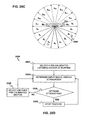
- Figure 11A is schematic diagram of a microphone array illustrating determination of a listening direction according to an embodiment of the present invention
- Figure 11B is a schematic diagram of a microphone array illustrating anti-causal filtering in conjunction with embodiments of the present invention
- Figure 12A is a schematic diagram of a microphone array and filter apparatus with which methods and apparatuses according to certain embodiments of the invention may be implemented;
- Figure 12B is a schematic diagram of an alternative microphone array and filter apparatus with which methods and apparatuses according to certain embodiments of the invention may be implemented;
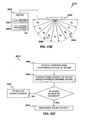
- Figure 13 is a flow diagram for processing a signal from an array of two or more microphones according to embodiments of the present invention.
- Figure 14 is a simplified block diagram illustrating a system, consistent with embodiments of methods and apparatus for adjusting a listening area for capturing sounds or capturing an audio signal based on a visual image or a location of the signal;
- Figure 15 illustrates an exemplary record consistent with embodiments of methods and apparatus for adjusting a listening area for capturing sounds or capturing an audio signal based on a visual image or a location of the signal;
- Figure 16 is a flow diagram consistent with embodiments of methods and apparatus for adjusting a listening area for capturing sounds or capturing an audio signal based on a visual image or a location of the signal;
- Figure 17 is a flow diagram consistent with embodiments of methods and apparatus for adjusting a listening area for capturing sounds or capturing an audio signal based on a visual image or a location of the signal;
- Figure 18 is a flow diagram consistent with embodiments of methods and apparatus for adjusting a listening area for capturing sounds or capturing an audio signal based on a visual image or a location of the signal;
- Figure 19 is a flow diagram consistent with embodiments of methods and apparatus for adjusting a listening area for capturing sounds or capturing an audio signal based on a visual image or a location of the signal;
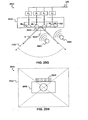
- Figure 20 is a diagram illustrating monitoring a listening zone based on a field of view consistent with embodiments of methods and apparatus for adjusting a listening area for capturing sounds or capturing an audio signal based on a visual image or a location of the signal;
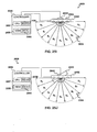
- Figure 21 is a diagram illustrating several listening zones consistent with embodiments of methods and apparatus for adjusting a listening area for capturing sounds or capturing an audio signal based on a visual image or a location of the signal;
- Figure 22 is a diagram focusing sound detection consistent with embodiments of methods and apparatus for adjusting a listening area for capturing sounds or capturing an audio signal based on a visual image or a location of the signal;
- Figures 23A, 23B , and 23C are schematic diagrams that illustrate a microphone array in which the methods and apparatuses for capturing an audio signal based on a location of the signal are implemented.
- Figure 24 is a diagram focusing sound detection consistent with one embodiment of the methods and apparatuses for capturing an audio signal based on a location of the signal.
- FIG. 25A is a schematic diagram of a microphone array according to an embodiment of the present invention.
- FIG. 25B is a flow diagram illustrating a method for targeted sound detection according to an embodiment of the present invention.
- FIG. 25C is a schematic diagram illustrating targeted sound detection according to a preferred embodiment of the present invention.
- FIG. 25D is a flow diagram illustrating a method for targeted sound, detection according to the preferred embodiment of the present invention.
- FIG. 25E is a top plan view of a sound source location and characterization apparatus according to an embodiment of the present invention.
- FIG. 25F is a flow diagram illustrating a method for sound source location and characterization according to an embodiment of the present invention.
- FIG. 25G is a top plan view schematic diagram of an apparatus having a camera and a microphone array for targeted sound detection from within a field of view of the camera according to an embodiment of the present invention.
- FIG. 25H is a front elevation view of the apparatus of FIG. 25E .
- FIGs. 25I-25J are plan view schematic diagrams of an audio-video apparatus according to an alternative embodiment of the present invention.
- FIG. 26 is a block diagram illustrating a signal processing apparatus according to an embodiment of the present invention.
- FIG. 27 is a block diagram of a cell processor implementation of a signal processing system according to an embodiment of the present invention.
- Embodiments of the present invention relate to methods and apparatus for facilitating the identification of specific sound sources and filtering out unwanted sound sources when sound is used as an interactive tool with a computer program.
- references to "electronic device”, “electronic apparatus” and “electronic equipment” include devices such as personal digital video recorders, digital audio players, gaming consoles, set top boxes, computers, cellular telephones, personal digital assistants, specialized computers such as electronic interfaces with automobiles, and the like.
- FIG. 1 shows a game environment 100 in which a video game program may be executed for interactivity with one or more users, in accordance with one embodiment of the present invention.
- player 102 is shown in front of a monitor 108 that includes a display 110.
- the monitor 108 is interconnected with a computing system 104.
- the computing system can be a standard computer system, a game console or a portable computer system.
- the game console can be a one manufactured by Sony Computer Entertainment Inc., Microsoft, or any other manufacturer.
- Computing system 104 is shown interconnected with an image-sound capture device 106 .
- the image-sound capture device 106 includes a sound capture unit 106a and an image capture unit 106b.
- the player 102 is shown interactively communicating with a game figure 112 on the display 110 .
- the video game being executed is one in which input is at least partially provided by the player 102 by way of the image capture unit 106b, and the sound capture unit 106a.
- the player 102 may move his hand so as to select interactive icons 114 on the display 110 .
- a translucent image of the player 102' is projected on the display 110 once captured by the image capture unit 106b.
- the player 102 knows where to move his hand in order to cause selection of icons or interfacing with the game figure 112 .
- the interactive icon 114 is an icon that would allow the player to select "swing" so that the game figure 112 will swing the object being handled.
- the player 102 may provide voice commands that can be captured by the sound capture unit 106a and then processed by the computing system 104 to provide interactivity with the video game being executed.
- the sound source 116a is a voice command to "jump!. The sound source 116a will then be captured by the sound capture unit 106a, and processed by the computing system 104 to then cause the game figure 112 to jump.
- Voice recognition may be used to enable the identification of the voice commands.
- the player 102 may be in communication with remote users connected to the internet or network, but who are also directly or partially involved in the interactivity of the game.
- the sound capture unit 106a may be configured to include at least two microphones which will enable the computing system 104 to select sound coming from particular directions. By enabling the computing system 104 to filter out directions which are not central to the game play (or the focus), distracting sounds in the game environment 100 will not interfere with or confuse the game execution when specific commands are being provided by the player 102 .
- the game player 102 may be tapping his feet and causing a tap noise which is a non-language sound 117 .
- Such sound may be captured by the sound capture unit 106a , but then filtered out, as sound coming from the player's feet 102 is not in the zone of focus for the video game. '
- the zone of focus is preferably identified by the active image area that is the focus point of the image capture unit 106b .
- the zone of focus can be manually or automatically selected from a choice of zones presented to the user after an initialization stage.
- the choice of zones may include one or more pre-calibrated listening zones.
- a pre-calibrated listening zone containing the sound source may be determined as set forth below.
- a game observer 103 may be providing a sound source 116b which could be distracting to the processing by the computing system during the interactive game play.
- the game observer 103 is not in the active image area of the image capture unit 106b and thus, sounds coming from the direction of game observer 103 will be filtered out so that the computing system 104 will not erroneously confuse commands from the sound source 116b with the sound sources coming from the player 102 , as sound source 116a .
- the image-sound capture device 106 includes an image capture unit 106b, and the sound capture unit 106a .
- the image-sound capture device 106 is preferably capable of digitally capturing image frames and then transferring those image frames to the computing system 104 for further processing.
- An example of the image capture unit 106b is a web camera, which is commonly used when video images are desired to be captured and then transferred digitally to a computing device for subsequent storage or communication over a network, such as the internet.
- Other types of image capture devices may also work, whether analog or digital, so long as the image data is digitally processed to enable the identification and filtering.
- the digital processing to enable the filtering is done in software, after the input data is received.
- the sound capture unit 106a is shown including a pair of microphones (MIC 1 and MIC 2) .
- the microphones are standard microphones, which can be integrated into the housing that makes up the image-sound capture device 106.
- Figure 3A illustrates sound capture units 106a when confronted with sound sources 116 from sound A and sound B .
- sound A will project its audible sound and will be detected by MIC 1 and MIC 2 along sound paths 201a and 201b.
- Sound B will be projected toward MIC 1 and MIC 2 over sound paths 202a and 202b .
- the sound paths for sound A will be of different lengths, thus providing for a relative delay when compared to sound paths 202a and 202b .
- the sound coming from each of sound A and sound B may then be processed using a standard triangulation algorithm so that direction selection can occur in box 216 , shown in Figure 3B .
- the sound coming from MIC 1 and MIC 2 will each be buffered in buffers 1 and 2 ( 210a , 210b ), and passed through delay lines ( 212a , 212b ).
- the buffering and delay process will be controlled by software, although hardware can be custom designed to handle the operations as well.
- direction selection 216 will trigger identification and selection of one of the sound sources 116 .
- the sound coming from each of MIC 1 and MIC 2 will be summed in box 214 before being output as the output of the selected source. In this manner, sound coming from directions other than the direction in the active image area will be filtered out so that such sound sources do not distract processing by the computer system 104 , or distract communication with other users that may be interactively playing a video game over a network, or the internet.
- FIG. 4 illustrates a computing system 250 that may be used in conjunction with the image-sound capture device 106 , in accordance with one embodiment of the present invention.
- the computing system 250 includes a processor 252 , and memory 256.
- a bus 254 will interconnect the processor and the memory 256 with the image-sound capture device 106 .
- the memory 256 will include at least part of the interactive program 258 , and also include selective sound source listening logic or code 260 for processing the received sound source data. Based on where the zone of focus is identified to be by the image capture unit 106b , sound sources outside of the zone of focus will be selectively filtered by the selective sound source listening logic 260 being executed (e.g., by the processor and stored at least partially in the memory 256 ).
- the computing system is shown in its most simplistic form, but emphasis is placed on the fact that any hardware configuration can be used, so long as the hardware can process the instructions to effect the processing of the incoming sound sources and thus enable the selective listening.
- the computing system 250 is also shown interconnected with the display 110 by way of the bus.
- the zone of focus is identified by the image capture unit being focused toward the sound source B . Sound coming from other sound sources, such as sound source A will be substantially filtered out by the selective sound source listening logic 260 when the sound is captured by the sound capture unit 106a and transferred to the computing system 250 .
- a player can be participating in an internet or networked video game competition with another user where each user's primary audible experience will be by way of speakers.
- the speakers may be part of the computing system or may be part of the monitor 108 .
- the local speakers are what is generating sound source A as shown in Figure 4 .
- the selective sound source listening logic 260 will filter out the sound of sound source A so that the competing user will not be provided with feedback of his or her own sound or voice. By supplying this filtering, it is possible to have interactive communication over a network while interfacing with a video game, while advantageously avoiding destructive feedback during the process.
- Figure 5 illustrates an example where the image-sound capture device 106 includes at least four microphones (MIC 1 through MIC 4).
- the sound capture unit 106a is therefore capable of triangulation with better granularity to identify the location of sound sources 116 ( A and B ). That is, by providing an additional microphone, it is possible to more accurately define the location of the sound sources and thus, eliminate and filter out sound sources that are not of interest or can be destructive to game play or interactivity with a computing system.
- sound source 116 ( B ) is the sound source of interest as identified by the video capture unit 106b .
- Figure 6 identifies how sound source B is identified to a spatial volume.
- the spatial volume at which sound source B is located will define the volume of focus 274.
- the image-sound capture device 106 will preferably include at least four microphones. At least one of the microphones will be in a different plane than three of the microphones. By maintaining one of the microphones in plane 271 and the remainder of the four in plane 270 of the image-sound capture device 106 , it is possible to define a spatial volume.
- noise coming from other people in the vicinity (shown as 276a and 276b ) will be filtered out as they do not lie within the spatial volume defined in the volume focus 274 . Additionally, noise that may be created just outside of the spatial volume, as shown by speaker 276c , will also be filtered out as it falls outside of the spatial volume.
- Figure 7 illustrates a flowchart diagram in accordance with one embodiment of the present invention.
- the method begins at operation 302 where input is received from one or more sound sources at two or more sound capture microphones.
- the two or more sound capture microphones are integrated into the image-sound capture device 106.
- the two or more sound capture microphones can be part of a second module/housing that interfaces with the image capture unit 106b.
- the sound capture unit 106a can include any number of sound capture microphones, and sound capture microphones can be placed in specific locations designed to capture sound from a user that may be interfacing with a computing system.
- the method moves to operation 304 where a delay path for each of the sound sources is determined.
- Example delay paths are defined by the sound paths 201 and 202 of Figure 3A .
- the delay paths define the time it takes for sound waves to travel from the sound sources to the specific microphones that are situated to capture the sound. Based on the delay it takes sound to travel from the particular sound sources 116 , the microphones can determine what the delay is and approximate location from which the sound is emanating from using a standard triangulation algorithm.
- a direction for each of the received inputs of the one or more sound sources is identified. That is, the direction from which the sound is originating from the sound sources 116 is identified relative to the location of the image-sound capture device, including the sound capture unit 106a . Based on the identified directions, sound sources that are not in an identified direction of a zone (or volume) of focus are filtered out in operation 308 . By filtering out the sound sources that are not originating from directions that are in the vicinity of the zone of focus, it is possible to use the sound source not filtered out for interactivity with a computer program, as shown in operation 310 .
- the interactive program can be a video game in which the user can interactively communicate with features of the video game, or players that may be opposing the primary player of the video game.
- the opposing player can either be local or located at a remote location and be in communication with the primary user over a network, such as the internet.
- the video game can also be played between a number of users in a group designed to interactively challenge each other's skills in a particular contest associated with the video game.
- Figure 8 illustrates a flowchart diagram in which image-sound capture device operations 320 are illustrated separate from the software executed operations that are performed on the received input in operations 340 .
- the method proceeds to operation 304 where in software, the delay path for each of the sound sources is determined. Based on the delay paths, a direction for each of the received inputs is identified for each of the one or more sound sources in operation 306 , as mentioned above.
- the method moves to operation 312 where the identified direction that is in proximity of video capture is determined. For instance, video capture will be targeted at an active image area as shown in Figure 1 . Thus, the proximity of video capture would be within this active image area (or volume), and any direction associated with a sound source that is within this or in proximity to this, image-active area, will be determined. Based on this determination, the method proceeds to operation 314 where directions (or volumes) that are not in proximity of video capture are filtered out. Accordingly, distractions, noises and other extraneous input that could interfere in video game play of the primary player will be filtered out in the processing that is performed by the software executed during game play.
- the primary user can interact with the video game, interact with other users of the video game that are actively using the video game, or communicate with other users over the network that may be logged into or associated with transactions for the same video game that is of interest.
- Such video game communication, interactivity and control will thus be uninterrupted by extraneous noises and/or observers that are not intended to be interactively communicating or participating in a particular game or interactive program.
- the embodiments described herein may also apply to online gaming applications. That is, the embodiments described above may occur at a server that sends a video signal to multiple users over a distributed network, such as the Internet, to enable players at remote noisy locations to communicate with each other. It should be further appreciated that the embodiments described herein may be implemented through either a hardware or a software implementation. That is, the functional descriptions discussed above may be synthesized to define a microchip having logic configured to perform the functional tasks for each of the modules associated with the noise cancellation scheme.
- the selective filtering of sound sources can have other applications, such as telephones.
- phone use environments there is usually a primary person (i.e., the caller) desiring to have a conversation with a third party (i.e., the callee).
- a third party i.e., the callee
- the phone being targeted toward the primary user (by the direction of the receiver, for example) can make the sound coming from the primary user's mouth the zone of focus, and thus enable the selection for listening to only the primary user.
- This selective listening will therefore enable the substantial filtering out of voices or noises that are not associated with the primary person, and thus, the receiving party will be able to receive a more clear communication from the primary person using the phone.
- Additional technologies may also include other electronic equipment that can benefit from taking in sound as an input for control or communication. For instance, a user can control settings in an automobile by voice commands, while avoiding other passengers from disrupting the commands.
- Other applications may include computer controls of applications, such as browsing applications, document preparation, or communications. By enabling this filtering, it is possible to more effectively issue voice or sound commands without interruption by surrounding sounds.
- any electronic apparatus may be controlled by voice commands in conjunction with any of the embodiments described herein.
- sound analysis it may be possible to filter out sound sources using sound analysis. If sound analysis is used, it is possible to use as few as one microphone. The sound captured by the single microphone can be digitally analyzed (in software or hardware) to determine which voice or sound is of interest. In some environments, such as gaming, it may be possible for the primary user to record his or her voice once to train the system to identify the particular voice. In this manner, exclusion of other voices or sounds will be facilitated. Consequently, it would not be necessary to identify a direction, as filtering could be done based one sound tones and/or frequencies.
- methods and apparatuses for adjusting a listening area for capturing sounds may be configured to identify different areas or volumes that encompass corresponding listening zones; Specifically, a microphone array may be configured to detect sounds originating from areas or volumes corresponding to these listening zones. Further, these areas or volumes may be a smaller subset of areas or volumes that are capable of being monitored for sound by the microphone array.
- the listening zone that is detected by the microphone array for sound may be dynamically adjusted such that the listening zone may be enlarged, reduced, or stay the same size but be shifted to a different location. For example, the listening zone may be further focused to detect a sound in a particular location such that the zone that is monitored is reduced from the initial listening zone.
- the level of the sound may be compared against a threshold level to validate the sound.
- the sound source from the particular location is monitored for continuing sound.
- the adjustment to the area or volume that is detected may be determined based on a zone of focus or field of view of an image capture device.
- the field of view of the image capture device may zoom in (magnified), zoom out (minimized), and/or rotate about a horizontal or vertical axis.
- the adjustments performed to the area that is detected by the microphone tracks the area associated with the current view of the image capture unit.
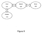
- FIG. 9 is a diagram illustrating an environment within which the methods and apparatuses for adjusting a listening area for capturing sounds, or capturing audio signals based on a visual image or a location of source of a sound signal are implemented.
- the environment includes an electronic device 410 (e.g., a computing platform configured to act as a client device, such as a personal digital video recorder, digital audio player, computer, a personal digital assistant, a cellular telephone, a camera device, a set top box, a gaming console), a user interface 415 , a network 420 (e.g., a local area network, a home network, the Internet), and a server 430 (e.g., a computing platform configured to act as a server).
- the network 420 can be implemented via wireless or wired solutions.
- one or more user interface 415 components are made integral with the electronic device 410 (e.g., keypad and video display screen input and output interfaces in the same housing as personal digital assistant electronics (e.g., as in a Clie® manufactured by Sony Corporation).
- one or more user interface 415 components e.g., a keyboard, a pointing device such as a mouse and trackball, a microphone, a speaker, a display, a camera
- the user utilizes interface 415 to access and control content and applications stored in electronic device 410 , server 430 , or a remote storage device (not shown) coupled via network 420 .
- embodiments of capturing an audio signal based on a location of the signal as described below are executed by an electronic processor in electronic device 410 , in server 430 , or by processors in electronic device 410 and in server 430 acting together.
- Server 430 is illustrated in Figure 1 as being a single computing platform, but in other instances are two or more interconnected computing platforms that act as a server.
- a user profile is selected from a plurality of user profiles.
- the user profile is accessed from an electronic device 410 and content associated with the user profile can be created, modified, and distributed to other electronic devices 410 .
- the content associated with the user profile includes a customized channel listing associated with television or musical programming and recording information associated with customized recording times.
- access to create or modify content associated with the particular user profile is restricted to authorized users.
- authorized users are based on a peripheral device such as a portable memory device, a dongle, and the like.
- each peripheral device is associated with a unique user identifier which, in turn, is associated with a user profile.
- FIG 10 is a simplified diagram illustrating an exemplary architecture in which the methods and apparatuses for capturing an audio signal based on a location of the signal are implemented.
- the exemplary architecture includes a plurality of electronic devices 410 , a server device 430 , and a network 420 connecting electronic devices 410 to server device 430 and each electronic device 410 to each other.
- the plurality of electronic devices 410 are each configured to include a computer-readable medium 509 , such as random access memory, coupled to an electronic processor 208 .
- Processor 208 executes program instructions stored in the computer-readable medium 209 .
- a unique user operates each electronic device 410 via an interface 415 as described with reference to Figure 9 .
- Server device 430 includes a processor 511 coupled to a computer-readable medium, such as a server memory 512 .
- the server device 430 is coupled to one or more additional external or internal devices, such as, without limitation, a secondary data storage element, such as database 540 .
- processors 508 and 511 are manufactured by Intel Corporation, of Santa Clara, California. In other instances, other microprocessors are used.
- the plurality of client devices 410 and the server 430 include instructions for a customized application for capturing an audio signal based on a location of the signal.
- the plurality of computer-readable media, e.g. memories 509 and 512 contain, in part, the customized application.
- the plurality of client devices 410 and the server device 430 are configured to receive and transmit electronic messages for use with the customized application.
- the network 420 is configured to transmit electronic messages for use with the customized application.
- One or more user applications may be stored in memories 509, in server memory 512, or a single user application is stored in part in one memory 509 and in part in server memory 512 .
- a stored user application regardless of storage location, is made customizable based on capturing an audio signal based on a location of the signal as determined using embodiments described below.
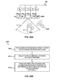
- a microphone array 602 may include four microphones M 0 , M 1 , M 2 , and M 3 .
- the microphones M 0 , M 1 , M 2 , and M 3 may be omni-directional microphones, i.e., microphones that can detect sound from essentially any direction. Omni-directional microphones are generally simpler in construction and less expensive than microphones having a preferred listening direction.
- Each signal x m generally includes subcomponents due to different sources of sounds.
- the subscript m range from 0 to 3 in this example and is used to distinguish among the different microphones in the array.
- TDA time delay of arrival
- BSS Blind Source Separation
- the blind source separation may involve an independent component analysis (ICA) that is based on second-order statistics.
- ICA independent component analysis
- x m ⁇ 1 ⁇ x mn a m ⁇ 11 ⁇ a m ⁇ 1 ⁇ n ⁇ ⁇ ⁇ a mn ⁇ 1 ⁇ a mnn • s 1 ⁇ s n
- Some embodiments of the invention use blind source separation (BSS) to determine a listening direction for the microphone array.
- the listening direction and/or one or more listening zones of the microphone array can be calibrated prior to run time (e.g., during design and/or manufacture of the microphone array) and re-calibrated at run time.
- the listening direction may be determined as follows.
- a user standing in a listening direction with respect to the microphone array may record speech for about 10 to 30 seconds.
- the recording room should not contain transient interferences, such as competing speech, background music, etc.
- Pre-determined intervals, e.g., about every 8 milliseconds, of the recorded voice signal are formed into analysis frames, and transformed from the time domain into the frequency domain.
- Voice-Activity Detection (VAD) may be performed over each frequency-bin component in this frame. Only bins that contain strong voice signals are collected in each frame and used to estimate its 2 nd -order statistics, for each frequency bin within the frame, i.e.
- Cal_Cov(j,k) E (( X' jk ) T * X' jk ), where E refers to the operation of determining the expectation value and ( X' jk ) T is the transpose of the vector X' jk .
- the vector X' jk is a M+1 dimensional vector representing the Fourier transform of calibration signals for the j th frame and the k th frequency bin.
- Each calibration covariance matrix Cal_Cov(j,k) may be decomposed by means of "Principal Component Analysis”(PCA) and its corresponding eigenmatrix C may be generated.
- PCA Principal Component Analysis
- the inverse C -1 of the eigenmatrix C may thus be regarded as a "listening direction” that essentially contains the most information to de-correlate the covariance matrix, and is saved as a calibration result.
- the term "eigenmatrix" of the calibration covariance matrix Cal_Cov(j,k) refers to a matrix having columns (or rows) that are the eigenvectors of the covariance matrix.
- ICA independent component analysis
- Recalibration in runtime may follow the preceding steps.
- the default calibration in manufacture takes a very large amount of recording data (e.g., tens of hours of clean voices from hundreds of persons) to ensure an unbiased, person-independent statistical estimation.
- the recalibration at runtime requires small amount of recording data from a particular person, the resulting estimation of C -1 is thus biased and person-dependant.
- PCA principal component analysis
- SBSS semi-blind source separation
- Embodiments of the invention may also make use of anti-causal filtering.
- the problem of causality is illustrated in FIG. 11B .
- one microphone e.g., M 0 is chosen as a reference microphone.
- signals from the source 604 must arrive at the reference microphone M 0 first.
- M 0 cannot be used as a reference microphone.
- the signal will arrive first at the microphone closest to the source 604 .
- Embodiments of the present invention adjust for variations in the position of the source 304 by switching the reference microphone among the microphones M 0 , M 1 , M 2 , M 3 in the array 302 so that the reference microphone always receives the signal first.
- this anti-causality may be accomplished by artificially delaying the signals received at all the microphones in the array except for the reference microphone while minimizing the length of the delay filter used to accomplish this.
- the fractional delay ⁇ t m may be adjusted based on a change in the signal to noise ratio (SNR) of the system output y(t).
- SNR signal to noise ratio
- the delay is chosen in a way that maximizes SNR.
- the total delay i.e., the sum of the ⁇ t m
- Figure 12A illustrates filtering of a signal from one of the microphones M 0 in the array 602.
- the signal from the microphone x 0 (t) is fed to a filter 702, which is made up of N+1 taps 704 0 ...704 N.
- each tap 704 1 includes a delay section, represented by a z-transform z -1 and a finite response filter.
- Each delay section introduces a unit integer delay to the signal x(t).
- the finite impulse response filters are represented by finite impulse response filter coefficients b 0 , b 1 , b 2 , b 3 ,... b N .
- the filter 702 may be implemented in hardware or software or a combination of both hardware and software.
- An output y(t) from a given filter tap 704 i is just the convolution of the input signal to filter tap 704 i with the corresponding finite impulse response coefficient b i . It is noted that for all filter taps 704 i except for the first one 704 0 the input to the filter tap is just the output of the delay section z -1 of the preceding filter tap 704 i-1 .
- the output of the filter 402 may be represented by:
- y t x t * b 0 + x ⁇ t - 1 * b 1 + x ⁇ t - 2 * b 2 + ... + x ⁇ t - N ⁇ b N .
- the general problem in audio signal processing is to select the values of the finite impulse response filter coefficients b 0 , b 1 ,..., b N that best separate out different sources of sound from the signal y(t).
- each delay z -1 is necessarily an integer delay and the size of the delay is inversely related to the maximum frequency of the microphone. This ordinarily limits the resolution of the apparatus 400A. A higher than normal resolution may be obtained if it is possible to introduce a fractional time delay ⁇ into the signal y(t) so that:
- y(t+A) x(t+ ⁇ )*b 0 + x(t-1+ ⁇ )*b 1 + x(t-2+ ⁇ )*b 2 +...+ x(t-N+ ⁇ )b N ,
- ⁇ is between zero and ⁇ 1.
- y t x t x ⁇ t - 1 ⁇ x ⁇ t - J T * b 00 b 01 ⁇ b 0 ⁇ j + x ⁇ t - 1 x ⁇ t - 2 ⁇ x ⁇ t - J - 1 T * b 10 b 11 ⁇ b 1 ⁇ J + ⁇ + x ⁇ t - N - J x ⁇ t - N - J + 1 ⁇ x ⁇ t - N T * b N ⁇ 0 b N ⁇ 1 ⁇ b NJ
- the quantity t+ ⁇ may be regarded as a mathematical abstract to explain the idea in time-domain.
- the signal y(t) may be transformed into the frequency-domain, so there is no such explicit "t+A”.
- an estimation of a frequency-domain function F(b i ) is sufficient to provide the equivalent of a fractional delay ⁇ .
- the above equation for the time domain output signal y(t) may be transformed from the time domain to the frequency domain, e.g., by taking a Fourier transform, and the resulting equation may be solved for the frequency domain output signal Y(k).
- the finite impulse response filter coefficients b ij for each row of the equation above may be determined by taking a Fourier transform of x(t) and determining the b ij through semi-blind source separation. Specifically, for each "row" of the above equation becomes:
- FT( ) represents the operation of taking the Fourier transform of the quantity in parentheses.
- FIG. 12B depicts an apparatus 700B having microphone array 602 of M+1 microphones M 0 , M 1 ... M M . Each microphone is connected to one of M+1 corresponding filters 702 0 , 702 1 ...702 M .
- Each of the filters 702 0 , 702 1 ...702 M includes a corresponding set of N+1 filter taps 704 00 ... 704 0N , 704 10 ...704 1N , 704 M0 ,.. 704 MN .
- each filter 702 m produces a corresponding output y m (t), which may be regarded as the components of the combined output y(t) of the filters. Fractional delays may be applied to each of the output signals y m (t) as described above.
- the quantities X j are generally (M+1)-dimensional vectors.
- M the quantities X j are generally (M+1)-dimensional vectors.
- the 4-channel inputs x m (t) are transformed to the frequency domain, and collected as a 1x4 vector "X jk ".
- the outer product of the vector X jk becomes a 4x4 matrix, the statistical average of this matrix becomes a "Covariance" matrix, which shows the correlation between every vector element.
- X 00 FT ⁇ x 0 ⁇ t - 0 , x 0 ⁇ t - 1 , x 0 ⁇ t - 2 , . ... x 0 ⁇ t - N - 1 + 0
- X 01 FT ⁇ x 0 ⁇ t - 1 , x 0 ⁇ t - 2 , x 0 ⁇ t - 3 , . ... x 0 ⁇ t - N - 1 + 1 .
- X 09 FT ⁇ x 0 ⁇ t - 9 , x 0 ⁇ t - 10 x 0 ⁇ t - 2 , . ... x 0 ⁇ t - N - 1 + 10
- X 01 FT ⁇ x 1 ⁇ t - 0 , x 1 ⁇ t - 1 , x 1 ⁇ t - 2 , . ... x 1 ⁇ t - N - 1 + 0
- X 11 FT ⁇ x 1 ⁇ t - 1 , x 1 ⁇ t - 2 , x 1 ⁇ t - 3 , . ... x 1 ⁇ t - N - 1 + 1 .
- X 19 FT ⁇ x 1 ⁇ t - 9 , x 1 ⁇ t - 10 x 1 ⁇ t - 2 , . ... x 1 ⁇ t - N - 1 + 10
- X 20 FT ⁇ x 2 ⁇ t - 0 , x 2 ⁇ t - 1 , x 2 ⁇ t - 2 , . ... x 2 ⁇ t - N - 1 + 0
- X 21 FT ⁇ x 2 ⁇ t - 1 , x 2 ⁇ t - 2 , x 2 ⁇ t - 3 , . ... x 2 ⁇ t - N - 1 + 1 .
- X 29 FT ⁇ x 2 ⁇ t - 9 , x 2 ⁇ t - 10 x 2 ⁇ t - 2 , . ... x 2 ⁇ t - N - 1 + 10
- X 30 FT ⁇ x 3 ⁇ t - 0 , x 3 ⁇ t - 1 , x 3 ⁇ t - 2 , . ... x 3 ⁇ t - N - 1 + 0
- X 31 FT ⁇ x 3 ⁇ t - 1 , x 3 ⁇ t - 2 , x 3 ⁇ t - 3 , . ... x 3 ⁇ t - N - 1 + 1 .
- X 39 FT ⁇ x 3 ⁇ t - 9 , x 3 ⁇ t - 10 x 3 ⁇ t - 2 , . ... x 3 ⁇ t - N - 1 + 10
- X jk X 0 ⁇ j k , X 1 ⁇ j k , X 2 ⁇ j k , X 3 ⁇ j k .
- the vector X jk is fed into the SBSS algorithm to find the filter coefficients b jn .
- ICA independent component analysis
- the components of each vector b jk are the corresponding filter coefficients for each frame j and each frequency bin k, i.e.,
- b jk [b 0j (k), b ij (k), b 2 j(k), b 3 j(k)].
- the independent frequency-domain components of the individual sound sources making up each vector X jk may be determined from:
- the ICA algorithm is based on "Covariance" independence, in the microphone array 302. It is assumed that there are always M+1 independent components (sound sources) and that their 2nd-order statistics are independent. In other words, the cross-correlations between the signals x 0 (t), x 1 (t), x 2 (t) and x 3 (t) should be zero. As a result, the non-diagonal elements in the covariance matrix Cov(j,k) should be zero as well.
- the unmixing matrix A becomes a vector A1 since it is has already been decorrelated by the inverse eigenmatrix C -1 which is the result of the prior calibration described above.
- Multiplying the run-time covariance matrix Cov(j,k) with the pre-calibrated inverse eigenmatrix C -1 essentially picks up the diagonal elements of A and makes them into a vector A1 .
- Each element of A1 is the strongest cross-correlation, the inverse of A will essentially remove this correlation.
- Each component Y i may be normalized to achieve a unit response for the filters.
- Figure 13 depicts a flow diagram illustrating one embodiment of the invention.
- a discrete time domain input signal x m (t) may be produced from microphones M 0 ...M M .
- a listening direction may be determined for the microphone array, e.g., by computing an inverse eigenmatrix C -1 for a calibration covariance matrix as described above.
- the-listening direction may be determined during-calibration of the-microphone array during design or manufacture or may be re-calibrated at runtime. Specifically, a signal from a source located in a preferred listening direction with respect to the microphone array may be recorded for a predetermined period of time.
- Analysis frames of the signal may be formed at predetermined intervals and the analysis frames may be transformed into the frequency domain.
- a calibration covariance matrix may be estimated from a vector of the analysis frames that have been transformed into the frequency domain.
- An eigenmatrix C of the calibration covariance matrix may be computed and an inverse of the eigenmatrix provides the listening direction.
- one or more fractional delays may be applied to selected input signals x m (t) other than an input signal x 0 (t) from a reference microphone M 0 .
- Each fractional delay is selected to optimize a signal to noise ratio of a discrete time domain output signal y(t) from the microphone array.
- the fractional delays are selected to such that a signal from the reference microphone M 0 is first in time relative to signals from the other microphone(s) of the array.
- the fractional delay may be introduced as described above with respect to Figures 4A and 4B .
- the listening direction (e.g., the inverse eigenmatrix C -1 ) determined in the Block 504 is used in a semi-blind source separation to select the finite impulse response filter coefficients, b 0 , b 1 ..., b N to separate out different sound sources from input signal x m (t).
- filter coefficients for each microphone m, each frame j and each frequency bin k, [b oj (k), b 1 j(k), ... b Mj (k)] may be computed that best separate out two or more sources of sound from the input signals x m (t).
- a runtime covariance matrix may be generated from each frequency domain input signal vector X jk .
- the runtime covariance matrix may be multiplied by the inverse C -1 of the eigenmatrix C to produce a mixing matrix A and a mixing vector may be obtained from a diagonal of the mixing matrix A.
- the values of filter coefficients may be determined from one or more components of the mixing vector. Further, the filter coefficients may represent a location relative to the microphone array in one embodiment. In another embodiment, the filter coefficients may represent an area relative to the microphone array.
- Figure 14 illustrates one embodiment of a system 900 for capturing an audio signal based on a location of the signal.
- the system 900 includes an area detection modules 910 , an area adjustment module 920 , a storage module 930 , an interface module 940 , a sound detection module 945 , a control module 950, an area profile module 960 , and a view detection module 970 .
- the control module 950 may communicate with the area detection module 910 , the area adjustment module 920 , the storage module 930 , the interface module 940 , the sound detection module 945 , the area profile module 960 , and the view detection module 970 .
- the control module 950 may coordinate tasks, requests, and communications between the area detection module 910 , the area adjustment module 920 , the storage module 930, the interface module 940, the sound detection module 945 , the area profile module 960, and the view detection module 970 .
- the area detection module 910 may detect the listening zone that is being monitored for sounds.
- a microphone array detects the sounds through a particular electronic device 410 .
- a particular listening zone that encompasses a predetermined area can be monitored for sounds originating from the particular area.
- the listening zone is defined by finite impulse response filter coefficients b 0 , b 1 ..., b N , as described above.
- the area adjustment module 920 adjusts the area defined by the listening zone that is being monitored for sounds.
- the area adjustment module 920 is configured to change the predetermined area that comprises the specific listening zone as defined by the area detection module 910.
- the predetermined area is enlarged.
- the predetermined area is reduced.
- the finite impulse response filter coefficients b 0 , b 1 ..., b N are modified to reflect the change in area of the listening zone.
- the storage module 930 may store a plurality of profiles wherein each profile is associated with a different specification for detecting sounds.
- the profile stores various information, e.g., as shown in an exemplary profile in Figure 15 .
- the.storage module 930 is located within the server device 430 .
- portions of the storage module 930 are located within the electronic device 410 .
- the storage module 930 also stores a representation of the sound detected.
- the interface module 940 detects the electronic device 410 as the electronic device 410 is connected to the network 420 .
- the interface module 940 detects input from the interface device 415 such as a keyboard, a mouse, a microphone, a still camera, a video camera, and the like.
- the interface module 640 provides output to the interface device 415 such as a display, speakers, external storage devices, an external network, and the like.
- the sound detection module 945 is configured to detect sound that originates within the listening zone.
- the listening zone is determined by the area detection module 910 . In another embodiment, the listening zone is determined by the area adjustment module 920 .
- the sound detection module 945 captures the sound originating from the listening zone. In another embodiment, the sound detection module 945 detects a location of the sound within the listening zone. The location of the sound may be expressed in terms of finite impulse response filter coefficients b 0 , b 1 ..., b N .
- the area profile module 960 processes profile information related to the specific listening zones for sound detection.
- the profile information may include parameters that delineate the specific listening zones that are being detected for sound. These parameters may include finite impulse response filter coefficients b 0 , b 1 ..., b N .
- exemplary profile information is shown within a record illustrated in Figure 15 .
- the area profile module 960 utilizes the profile information.
- the area profile module 960 creates additional records having additional profile information.
- the view detection module 970 detects the field of view of a image capture unit such as a still camera or video camera.
- the view detection module 970 is configured to detect the viewing angle of the image capture unit as seen through the image capture unit.
- the view detection module 970 detects the magnification level of the image capture unit.
- the magnification level may be included within the metadata describing the particular image frame.
- the view detection module 970 periodically detect the field of view such that as the image capture unit zooms in or zooms out, the current field of view is detected by the view detection module 970.
- the view detection module 970 detects the horizontal and vertical rotational positions of the image capture unit relative to the microphone array.
- the system 900 in Figure 14 is shown for the purpose of example and is merely one embodiment of the methods and apparatuses for capturing an audio signal based on a location of the signal. Additional modules may be added to the system 900 without departing from the scope of the methods and apparatuses for capturing an audio signal based on a location of the signal. Similarly, modules may be combined or deleted without departing from the scope of the methods and apparatuses for adjusting a listening area for capturing sounds or for capturing an audio signal based on a visual image or a location of a source of a sound signal.
- Figure 15 illustrates a simplified record 1000 that corresponds to a profile that describes the listening area.
- the record 1000 is stored within the storage module 930 and utilized within the system 900 .
- the record 1000 includes a user identification field 1010 , a profile name field 1020 , a listening zone field 1030 , and a parameters field 1040 .
- the user identification field 1010 provides a customizable label for a particular user.
- the user identification field 1010 may be labeled with arbitrary names such as "Bob”, “Emily's Profile”, and the like.
- the profile name field 1020 uniquely identifies each profile for detecting sounds.
- the profile name field 1020 describes the location and/or participants.
- the profile name field 1020 may be labeled with a descriptive name such as "The XYZ Lecture Hall”, "The Sony PlayStation® ABC Game”, and the like.
- the profile name field 1020 may be further labeled "The XYZ Lecture Hall with half capacity", The Sony PlayStation® ABC Game with 2 other Participants", and the like.
- the listening zone field 1030 identifies the different areas that are to be monitored for sounds. For example, the entire XYZ Lecture Hall may be monitored for sound. However, in another embodiment, selected portions of the XYZ Lecture Hall are monitored for sound such as the front section, the back section, the center section, the left section, and/or the right section.
- the entire area surrounding the Sony PlayStation® may be monitored for sound.
- selected areas surrounding the Sony PlayStation® are monitored for sound such as in front of the Sony PlayStation®, within a predetermined distance from the Sony PlayStation®, and the like.
- the listening zone field 1030 includes a single area for monitoring sounds. In another embodiment, the listening zone field 1030 includes multiple areas for monitoring sounds.
- the parameter field 1040 describes the parameters that are utilized in configuring the sound detection device to properly detect sounds within the listening zone as described within the listening zone field 1030.
- the parameter field 1040 includes finite impulse response filter coefficients b 0 , b 1 ..., b N .
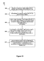
- the flow diagrams as depicted in Figures 16 , 17 , 18 , and 19 illustrate examples of embodiments of methods and apparatus for adjusting a listening area for capturing sounds or for capturing an audio signal based on a visual image or a location of a source of a sound signal.
- the blocks within the flow diagrams can be performed in a different sequence without departing from the spirit of the methods and apparatus for capturing an audio signal based on a location of the signal. Further, blocks can be deleted, added, or combined without departing from the spirit of such methods and apparatus.
- the flow diagram in Figure 16 illustrates adjusting a method for listening area for capturing sounds adjusting a listening area for capturing sounds. Such a method may be used in conjunction with capturing an audio signal based on a location of a source of a sound signal according to one embodiment of the invention.
- an initial listening zone is identified for detecting sound.
- the initial listening zone may be identified within a profile associated with the record 1000.
- the area profile module 960 may provide parameters associated with the initial listening zone.
- the initial listening zone is pre-programmed into the particular electronic device 410 .
- the particular location such as a room, lecture hall, or a car are determined and defined as the initial listening zone.
- multiple listening zones are defined that collectively comprise the audibly detectable areas surrounding the microphone array.
- Each of the listening zones is represented by finite impulse response filter coefficients b 0 , b 1 ..., b N .
- the initial listening zone is selected from the multiple listening zones in one embodiment.
- the initial listening zone is initiated for sound detection.
- a microphone array begins detecting sounds. In one, instance, only the sounds within the initial listening zone are recognized by the device 410 . In one example, the microphone array may initially detect all sounds. However, sounds that originate or emanate from outside of the initial listening zone are not recognized by the device 410. In one embodiment, the area detection module 1110 detects the sound originating from within the initial listening zone.
- Block 1130 sound detected within the defined area is captured.
- a microphone detects the sound.
- the captured sound is stored within the storage module 930 .
- the sound detection module 945 detects the sound originating from the defined area.
- the defined area includes the initial listening zone as determined by the Block 1110 .
- the defined area includes the area corresponding to the adjusted defined area of the Block 1160.
- the defined area may be enlarged. For example, after the initial listening zone is established, the defined area may be enlarged to encompass a larger area to monitor sounds.
- the defined area may be reduced. For example, after the initial listening zone is established, the defmed area may be reduced to focus on a smaller area to monitor sounds.
- the size of the defined area may remain constant, but the defined area is rotated or shifted to a different location.
- the defined area may be pivoted relative to the microphone array.
- adjustments to the defined area may also be made after the first adjustment to the initial listening zone is performed.
- the signals indicating an adjustment to the defined area may be initiated based on the sound detected by the sound detection module 945, the field of view detected by the view detection module 970 , and/or input received through the interface module 940 indicating a change an adjustment in the defined area.
- Block 1150 if an adjustment to the defined area is detected, then the defined area is adjusted in Block 1160 .
- the finite impulse response filter coefficients b 0 , b 1 ..., b N are modified to reflect an adjusted defined area in the Block 1160 .
- different filter coefficients are utilized to reflect the addition or subtraction of listening zone(s).
- Block 1150 if an adjustment to the defined area is not detected, then sound within the defined area is detected in the Block 830.
- the flow diagram in Figure 12 illustrates creating a listening zone, selecting a listening zone, and monitoring sounds according to one embodiment of the invention.
- the listening zones are defmed.
- the field covered by the microphone array includes multiple listening zones.
- the listening zones are defined by segments relative to the microphone array.
- the listening zones may be defined as four different quadrants such as Northeast, Northwest, Southeast, and Southwest, where each quadrant is relative to the location of the microphone array located at the center.
- the listening area may be divided into any number of listening zones.
- the listening area may be defined by listening zones encompassing X number of degrees relative to the microphone array. If the entire listening area is a full coverage of 360 degrees around the microphone array, and there are 10 distinct listening zones, then each listening zone or segment would encompass 36 degrees.
- each of the listening zones corresponds with a set of finite impulse response filter coefficients b 0 , b 1 ..., b N .
- the specific listening zones may be saved within a profile stored within the record 1000 .
- the finite impulse response filter coefficients b 0 , b 1 ..., b N may also be saved within the record 1000.
- sound is detected by the microphone array for the purpose of selecting a listening zone.
- the location of the detected sound may also be detected.
- the location of the detected sound is identified through a set of finite impulse response filter coefficients b 0 , b 1 ..., b N .
- At least one listening zone is selected.
- the selection of particular listening zone(s) is utilized to prevent extraneous noise from interfering with sound intended to be detected by the microphone array. By limiting the listening zone to a smaller area, sound originating from areas that are not being monitored can be minimized.
- the listening zone is automatically selected. For example, a particular listening zone can be automatically selected based on the sound detected within the Block 1215 . The particular listening zone that is selected can correlate with the location of the sound detected within the Block 1215 . Further, additional listening zones can be selected that are in adjacent or proximal to listening zones relative to the detected sound. In another example, the particular listening zone is selected based on a profile within the record 1200 .
- the listening zone is manually selected by an operator.
- the detected sound may be graphically displayed to the operator such that the operator can visually detect a graphical representation that shows which listening zone corresponds with the location of the detected sound. Further, selection of the particular listening zone(s) may be performed based on the location of the detected sound. In another Example, the listening zone may be selected solely based on the anticipation of sound.
- sound is detected by the microphone array.
- any sound is captured by the microphone array regardless of the selected listening zone.
- the information representing the sound detected is analyzed for intensity prior to further analysis. In one instance, if the intensity of the detected sound does not meet a predetermined threshold, then the sound is characterized as noise and is discarded.
- Block 1240 if the sound detected within the Block 1230 is found within one of the selected listening zones from the Block 1220 , then information representing the sound is transmitted to the operator in Block 1250 .
- the information representing the sound may be played, recorded, and/or further processed.
- Block 1240 if the sound detected within the Block 1230 is not found within one of the selected listening zones then further analysis is performed per Block 1245 .
- a confirmation is requested by the operator in Block 1260 .
- the operator is informed of the sound detected outside of the selected listening zones and is presented an additional listening zone that includes the region that the sound originates from within.
- the operator is given the opportunity to include this additional listening zone as one of the selected listening zones.
- a preference of including or not including the additional listening zone can be made ahead of time such that additional selection by the operator is not requested.
- the inclusion or exclusion of the additional listening zone is automatically performed by the system 1200 .
- the selected listening zones are updated in the Block 1220 based on the selection in the Block 1260. For example, if the additional listening zone is selected, then the additional listening zone is included as one of the selected listening zones.
- the flow diagram in Figure 18 illustrates adjusting a listening zone based on the field of view according to one embodiment of the invention.
- a listening zone is selected and initialized.
- a single listening zone is selected from a plurality of listening zones.
- multiple listening zones are selected.
- the microphone array monitors the listening zone.
- a listening zone can be represented by finite impulse response filter coefficients b 0 , b 1 ..., b N or a predefined profile illustrated in the record 1000 .
- the field of view is detected.
- the field of view represents the image viewed through a image capture unit such as a still camera, a video camera, and the like.
- the view detection module 970 is utilized to detect the field of view.
- the current field of view can change as the effective focal length (magnification) of the image capture unit is varied. Further, the current view of field can also change if the image capture unit rotates relative to the microphone array.
- the current field of view is compared with the current listening zone(s).
- the magnification of the image capture unit and the rotational relationship between the image capture unit and the microphone array are utilized to determine the field of view. This field of view of the image capture unit is compared with the current listening zone(s) for the microphone array.
- the current listening zone is adjusted in Block 1340 . If the rotational position of the current field of view and the current listening zone of the microphone array are not aligned, then a different listening zone is selected that encompasses the rotational position of the current field of view.
- the current listening zone may be deactivated such that the deactivated listening zone is no longer able to detect sounds from this deactivated listening zone.
- the current listening zone may be modified through manipulating the finite impulse response filter coefficients b 0 , b 1 ..., b N to reduce the area that sound is detected by the current listening zone.
- the current listening zone may be modified through manipulating the finite impulse response filter coefficients b 0 , b 1 ..., b N to increase the area that sound is detected by the current listening zone.
- the flow diagram in Figure 19 illustrates adjusting a listening zone based on the field of view according to one embodiment of the invention.
- a listening zone is selected and initialized.
- a single listening zone is selected from a plurality of listening zones.
- multiple listening zones are selected.
- the microphone array monitors the listening zone.
- a listening zone can be represented by finite impulse response filter coefficients b 0 , b 1 ..., b N or a predefined profile illustrated in the record 1000 .
- sound is detected within the current listening zone(s).
- the sound is detected by the microphone array through the sound detection module 945 .
- a sound level is determined from the sound detected within the Block 1420 .
- the sound level determined from the Block 1430 is compared with a sound threshold level.
- the sound threshold level is chosen based on sound models that exclude extraneous, unintended noise.
- the sound threshold is dynamically chosen based on the current environment of the microphone array. For example, in a very quiet environment, the sound threshold may be set lower to capture softer sounds. In contrast, in a loud environment, the sound threshold may be set higher to exclude background noises.
- the location of the detected sound is determined in Block 1445.
- the location of the detected sound is expressed in the form of finite impulse response filter coefficients b 0 , b 1 ..., b N .
- the listening zone that is initially selected in the Block 1410 is adjusted.
- the area covered by the initial listening zone is decreased.
- the location of the detected sound identified from the Block 1445 is utilized to focus the initial listening zone such that the initial listening zone is adjusted to include the area adjacent to the location of this sound.
- the listening zone that includes the location of the sound is retained as the adjusted listening zone.
- the listening zone that that includes the location of the sound and an adjacent listening zone are retained as the adjusted listening zone.
- the adjusted listening zone can be configured as a smaller area around the location of the sound.
- the smaller area around the location of the sound can be represented by finite impulse response filter coefficients b 0 , b 1 ..., b N that identify the area immediately around the location of the sound.
- the sound is detected within the adjusted listening zone(s).
- the sound is detected by the microphone array through the.sound detection module 945 .
- the sound level is also detected from the adjusted listening zone(s).
- the sound detected within the adjusted listening zone(s) may be recorded, streamed, transmitted, and/or further processed by the system 900 .
- the sound level determined from the Block 1460 is compared with a sound threshold level.
- the sound threshold level is chosen to determine whether the sound originally detected within the Block 1420 is continuing.
- the adjusted listening zone(s) is further adjusted in Block 1480 .
- the adjusted listening zone reverts back to the initial listening zone shown in the Block 1410 .
- an electronic device 1500 includes a microphone array and an image capture unit, e.g., as describe above.
- Objects 1510 , 1520 can be regarded as sources of sound.
- the device 1500 is a camcorder.
- the device 1500 is capable of capturing sounds and visual images within regions 1530 , 1540 , and 1550 .
- the device 1500 can adjust a field of view for capturing visual images and can adjust the listening zone for capturing sounds.
- the regions 1530, 1540, and 1550 are chosen as arbitrary regions. There can be fewer or additional regions that are larger or smaller in different instances.
- the device 1500 captures the visual image of the region 1540 and the sound from the region 1540 . Accordingly, sound and visual images from the object 1520 may be captured. However, sounds and visual images from the object 1510 will not be captured in this instance.
- the field of view of the device 1500 may be enlarged from the region 1540 to encompass the object 1510 . Accordingly, the sound captured by the device 1500 follows the visual field of view and also enlarges the listening zone from the region 1540 to encompass the object 1510 .
- the visual image of the device 1500 may cover the same footprint as the region 1540 but be rotated to encompass the object 1510 . Accordingly, the sound captured by the device 1500 follows the visual field of view and the listening zone rotates from the region 1540 to encompass the object 1510 .
- Figure 21 illustrates a diagram that illustrates a use of the method described in Figure 19 .
- Figure 21 depicts a microphone array 1600, and objects 1610, 1620.
- the microphone array 1600 is capable of capturing sounds within regions 1630, 1640, and 1650. Further, the microphone array 1600 can adjust the listening zone for capturing sounds.
- the regions 1630, 1640, and 1650 are chosen as arbitrary regions. There can be fewer or additional regions that are larger or smaller in different instances.
- the microphone array 1600 monitors sounds from the regions 1630, 1640, and 1650.
- the microphone array 1600 narrows sound detection to the region 1650.
- the microphone array 1600 is capable of detecting sounds from the regions 1630, 1640, and 1650.
- the microphone array 1600 can be integrated within a Sony PlayStation® gaming device.
- the objects 1610 and 1620 represent players to the left and right of the user of the PlayStation® device, respectively.
- the user of the PlayStation® device can monitor fellow players or friends on either side of the user while blocking out unwanted noises by narrowing the listening zone that is monitored by the microphone array. 1600 for capturing sounds.
- Figure 22 illustrates a diagram that illustrates a use of an application in conjunction with the system 900 as described within Figure 14 .
- Figure 22 depicts a microphone array 1700 , an object 1710 , and a microphone array 1740 .
- the microphone arrays 1700 and 1740 are capable of capturing sounds within a region 1705 which includes a region 1750 . Further, both microphone arrays 1700 and 1740 can adjust their respective listening zones for capturing sounds.
- the microphone arrays 1700 and 1740 monitor sounds within the region 1705. When the object 1710 produces a sound that exceeds the sound level threshold, then the microphone arrays 1700 and 1740 narrows sound detection to the region . 1750. In one embodiment, the region 1750 is bounded by traces 1720, 1725, 1750, and 1755. After the sound terminates, the microphone arrays 1700 and 1740 return to monitoring sounds within the region 1705 .
- the microphone arrays 1700 and 1740 are combined within a single microphone array that has a convex shape such that the single microphone array can be functionally substituted for the microphone arrays 1700 and 1740 .
- the microphone array 602 as shown within Figure 11A illustrates one embodiment for a microphone array.
- Figures 23A, 23B , and 23C illustrate other embodiments of microphone arrays.
- Figure 23A illustrates a microphone array 1810 that includes microphones 1802 , 1804, 1806, 1808, 1810, 1812, 1814, and 1816 .
- the microphone array 1810 is shaped as a rectangle and the microphones 1802 , 1804, 1806, 1808, 1810, 1812, 1814, and 1816 are located on the same plane relative to each other and are positioned along the perimeter of the microphone array 1810 . In other embodiments, there are fewer or additional microphones. Further, the positions of the microphones 1802, 1804, 1806, 1808, 1810, 1812, 1814, and 1816 can vary in other embodiments.
- Figure 23B illustrates a microphone array 1830 that includes microphones 1832, 1834, 1836, 1838, 1840, 1842, 1844, and 1846 .
- the microphone array 1830 is shaped as a circle and the microphones 1832, 1834, 1836, 1838, 1840, 1842, 1844, and 1846 are located on the same plane relative to each other and are positioned along the perimeter of the microphone array 1530 . In other embodiments, there are fewer or additional microphones. Further, the positions of the microphones 1832, 1834, 1836, 1838, 1840, 1842, 1844, and 1846 can vary in other embodiments.
- Figure 23C illustrates a microphone array 1860 that includes microphones 1862, 1864, 1866, and 1868.
- the microphones 1862, 1864, 1866, and 1868 distributed in a three dimensional arrangement such that at least one of the microphones is located on a different plane relative to the other three.
- the microphones 1862, 1864, 1866, and 1868 may be located along the outer surface of a three dimensional sphere. In other embodiments, there may be fewer or additional microphones. Further, the positions of the microphones 1862, 1864, 1866, and 1868 can vary in other embodiments.
- Figure 24 illustrates a diagram that illustrates a use of an application in conjunction with the system 900 as described within Figure 14 .
- Figure 24 includes a microphone array 1910 and an object 1915 .
- the microphone array 1910 is capable of capturing sounds within a region 1900 . Further, the microphone array 1910 can adjust the listening zones for capturing sounds from the object 1915 .
- the microphone array 1910 monitors sounds within the region 1900 .
- a component of a controller coupled to the microphone array 1910 e.g., area adjustment module 620 of system 600 of Figure 6
- the region 1915 is bounded by traces 1930, 1940, 1950, and 1960 .
- the region 1915 represents a three dimensional spatial volume in which sound is captured by the microphone array 1910 .
- the microphone array 1910 utilizes a two dimensional array.
- the microphone arrays 1800 and 1830 as shown in Figures 23A and 23B , respectively, are each one embodiment of a two dimensional array.
- the region 1915 can be represented by finite impulse response filter coefficients b 0 , b 1 ..., b N as a spatial volume.
- the region 1915 is bounded by traces 1930, 1940, 1950, and 1960 .
- the region 1915 is bounded by traces 1940 and 1950 in another embodiment.
- the microphone array 1910 utilizes a three dimensional array such as the microphone array 1860 as shown within Figure 23C .
- the region 1915 can be represented by finite impulse response filter coefficients b 0 , b 1 ..., b N as a spatial volume.
- the region 1915 is bounded by traces 1930, 1940, 1950, and 1960 .
- the three dimensional array utilizes TDA detection in one embodiment.
- a microphone array 2002 may include four microphones M 0 , M 1 , M 2 , and M 3 that are coupled to corresponding signal filters F 0 , F 1 , F 2 and F 3 .
- Each of the filters may implement some combination of finite impulse response (FIR) filtering and time delay of arrival (TDA) filtering.
- FIR finite impulse response
- TDA time delay of arrival
- the microphones M 0 , M 1 , M 2 , and M 3 may be omni-directional microphones, i.e., microphones that can detect sound from essentially any direction.
- Omni-directional microphones are generally simpler in construction and less expensive than microphones having a preferred listening direction.
- the microphones M 0 , M 1 , M 2 , and M 3 produce corresponding outputs x 0 (t), x t (t), X 2 (t), X 3 (t). These outputs serve as inputs to the filters F 0 , F 1 , F 2 and F 3 .
- Each filter may apply a time delay of arrival (TDA) and/or a finite impulse response: (FIR) to its input.
- TDA time delay of arrival
- FIR finite impulse response
- the outputs of the filters may be combined into a filtered output y(t).
- FIG. 25A depicts a linear array of microphones for the sake of example, embodiments of the invention are not limited to such configurations.
- three or more microphones may be arranged in a two-dimensional array, or four or more microphones may be arranged in a three-dimensional array as discussed above.
- a system based on 2-microphone array may be incorporated into a controller unit for a video game.
- Each signal X m generally includes subcomponents due to different sources of sounds. The subscript m ranges from 0 to 3 in this example and is used to distinguish among the different microphones in the array.
- the filters F 0 , F 1 , F 2 and F 3 are pre-calibrated with filter parameters (e.g., FIR filter coefficients and/or TDA values) that define one or more pre-calibrated listening zones Z .
- Each listening zone Z is a region of space proximate the microphone array 2002 .
- the parameters are chosen such that sounds originating from a source 2004 located within the listening zone Z are detected while sounds originating from a source 2006 located outside the listening zone Z are filtered out, i.e., substantially attenuated.
- the listening zone Z is depicted as being a more or less wedge-shaped sector having an origin located at or proximate the center of the microphone array 2002 .
- the listening zone Z may be a discrete volume, e.g., a rectangular, spherical, conical or arbitrarily-shaped volume in space.
- Wedge-shaped listening zones can be robustly established using a linear array of microphones.
- Robust listening zones defined by arbitrarily-shaped volumes may be established using a planar array or an array of at least four microphones where in at least one microphone lies in a different plane from the others, e.g., as illustrated in Figure 6 and in Figure 23C .
- Such an array is referred to herein as a "concave" microphone array.
- a method 2010 for targeted voice detection using the microphone array 2002 may proceed as follows. As indicated at 2012, one or more sets of the filter coefficients for the filters F 0 , F 1 , F 2 and F 3 are determined corresponding to one or more pre-calibrated listening zones Z .
- the filters F 0 , F 1 , F 2 , and F 3 may be implemented in hardware or software, e.g., using filters 702 0 ..702 M with corresponding filter taps 704 mi having delays z -1 and finite impulse response filter coefficients b mi as described above with respect to Figure 12A and Figure 12B .
- Each set of filter coefficients is selected to detect portions of the input signals corresponding to sounds originating within a given listening sector and filters out sounds originating outside the given listening sector.
- one or more known calibration sound sources may be placed at several different known locations within and outside the sector S.
- the calibration source(s) may emit sounds characterized by known spectral distributions similar to sounds the microphone array 2002 is likely to encounter at runtime. The known locations and spectral characteristics of the sources may then be used to select the values of the filter parameters for the filters F 0 , F 1 , F 2 and F 3
- Blind Source Separation may be used to pre-calibrate the filters F 0 , F 1 , F 2 and F 3 to define the listening zone Z .
- Blind source separation separates a set of signals into a set of other signals, such that the regularity of each resulting signal is maximized, and the regularity between the signals is minimized (i.e., statistical independence is maximized or decorrelation is minimized).
- the blind source separation may involve an independent component analysis (ICA) that is based on second-order statistics.
- ICA independent component analysis
- the listening zones Z of the microphone array 2002 can be calibrated prior to run time (e.g., during design and/or manufacture of the microphone array) and may optionally be re-calibrated at run time.
- the listening zone Z may be pre-calibrated by recording a person speaking within the listening and applying second order statistics to the recorded speech as described above with respect to Figures 11A, 11B, 12A , 12B and 13 regarding the calibration of the listening direction.
- the calibration process may be refined by repeating the above procedure with the user standing at different locations within the listening zone Z .
- microphone-array noise reduction it is preferred for the user to move around inside the listening sector during calibration so that the beamforming has a certain tolerance (essentially forming a listening cone area) that provides a user some flexible moving space while talking.
- voice/sound detection need not be calibrated for the entire cone area of the listening sector S. Instead the listening sector is preferably calibrated for a very narrow beam B along the center of the listening zone Z, so that the final sector determination based on noise suppression ratio becomes more robust.
- the process may be repeated for one or more additional listening zones.
- a particular pre-calibrated listening zone Z may be selected at a runtime by applying to the filters F 0 , F 1 , F 2 and F 3 a set of filter parameters corresponding to the particular pre-calibrated listening zone Z .
- the microphone array may detect sounds originating within the particular listening sector and filter out sounds originating outside the particular listening sector.
- a single listening sector is shown in FIG. 25A , embodiments of the present invention may be extended to situations in which a plurality of different listening sectors are pre-calibrated.
- the microphone array 2002 can then track between two or more pre-calibrated sectors at runtime to determine in which sector a sound source resides.
- the space surrounding the microphone array 2002 may be divided into multiple listening zones in the form of eighteen different pre-calibrated 20 degree wedge-shaped listening sectors S 0 ... S 17 that encompass about 360 degrees surrounding the microphone array 2002 by repeating the calibration procedure outlined above each of the different sectors and associating a different set of FIR filter coefficients and TDA values with each different sector.
- an appropriate set of pre-determined filter settings e.g., FIR filter coefficients and/or TDA values determined during calibration as described above
- any of the listening sectors S 0 ...S 17 may be selected.
- the microphone array 2002 can switch from one sector to another to track a sound source 2004 from one sector to another.
- the sound source 2004 is located in sector S 7 and the filters F 0 , F 1 , F 2 , F 3 are set to select sector S 4 . Since the filters are set to filter out sounds coming from outside sector S 4 the input energy E of sounds from the sound source 2004 will be attenuated.
- the input energy E may be defined as a dot product:
- x m T t is the transpose of the vector x m (t), which represents microphone output x m (t). And the sum is an average taken over all M microphones in the array.
- the attenuation of the input energy E may be determined from the ratio of the input energy E to the filter output energy, i.e.:
- Attenuation 1 / M ⁇ ⁇ m x m T t ⁇ x m t y T t ⁇ y t . . If the filters are set to select the sector containing the sound source 2004 the attenuation is approximately equal to 1. Thus, the sound source 2004 may be tracked by switching the settings of the filters F 0 , F 1 , F 2 , F 3 from one sector setting to another and determining the attenuation for different sectors.
- a targeted voice detection 2020 method using determination of attenuation for different listening sectors may proceed as depicted in the flow diagram of FIG. 25D . At 2022 any pre-calibrated listening sector may be selected initially.
- sector S 4 which corresponds roughly to a forward listening direction, may be selected as a default initial listening sector.
- an input signal energy attenuation is determined for the initial listen sector. If, at 2026 the attenuation is not an optimum value another pre-calibrated sector may be selected at 2028.
- the correct sector may be "behind" the microphone array 2002 , e.g., in sectors S 9 ... S 17 -In many cases the mounting of the microphone array may introduce a built-in attenuation of sounds coming from these sectors such that there is a minimum attenuation, e.g., of about 1 dB, when the source 2004 is located in any of these sectors. Consequently it may be determined from the input signal attenuation whether the source 2004 is "in front" or "behind” the microphone array 2002.
- the sound source 2004 might be expected to be closer to the microphone having the larger input signal energy.
- the right hand microphone M 3 would have the larger input signal energy and, by process of elimination, the sound source 2004 would be in one of sectors S 6 , S 7 , S 8 , S 9 , S 10 , S 11 , S 12.
- the next sector selected is one that is approximately 90 degrees away from the initial sector S 4 in a direction toward the right hand microphone M 3 , e.g., sector S 8 .
- the input signal energy attenuation for sector S 8 may be determined as indicated at 2024 .
- next sector may be one that is approximately 45 degrees away from the previous sector in the direction back toward the initial sector, e.g., sector S 6 .
- the input signal energy attenuation may be determined and compared to the optimum attenuation. If the input signal energy is not close to the optimum only two sectors remain in this example. Thus, for the example depicted in FIG. 25C , in a maximum of four sector switches, the correct sector may be determined. The process of determining the input signal energy attenuation and switching between different listening sectors may be accomplished in about 100 milliseconds if the input signal is sufficiently strong.
- FIG. 25E depicts an example of a sound source location and characterization apparatus 2030 having a microphone array 2002 described above coupled to an electronic device 2032 having a processor 2034 and memory 2036 .
- the device may be a video game, television or other consumer electronic device.
- the processor 2034 may execute instructions that implement the FIR filters and time delays described above.
- the memory 2036 may contain data 2038 relating to pre-calibration of a plurality of listening zones.
- the pre-calibrated listening zones may include wedge shaped listening sectors S 0 , S 1 , S 2 , S 3 , S 4 , S 5 , S 6 , S 7 , S 8 .
- the instructions run by the processor 2034 may operate the apparatus 2030 according to a method as set forth in the flow diagram 2031 of FIG. 25F .
- Sound sources 2004, 2005 within the listening zones can be detected using the microphone array 2002 .
- One sound source 2004 may be of interest to the device 2032 or a user of the device.
- Another sound source 2005 may be a source of background noise or otherwise not of interest to the device 2032 or its user.
- the apparatus 2030 determines which listening zone contains the sound's source 2004 as indicated at 2033 of FIG. 25F .
- the iterative sound source sector location routine described above with respect to Figures 25C through 25D may be used to determine the pre-calibrated listening zones containing the sound sources 2004, 2005 (e.g., sectors S 3 and S 6 respectively).
- the microphone array may be refocused on the sound source, e.g., using adaptive beam forming.
- adaptive beam forming techniques is described, e.g., in US Patent Application Publication Number 2005/0047611 A1. to Xiadong Mao , which is incorporated herein by reference.
- the sound source 2004 may then be characterized as indicated at 2035, e.g., through analysis of an acoustic spectrum of the sound signals originating from the sound source. Specifically, a time domain signal from the sound source may be analyzed over a predetermined time window and a fast Fourier transform (FFT) may be performed to obtain a frequency distribution characteristic of the sound source.
- FFT fast Fourier transform
- the detected frequency distribution may be compared to a known acoustic model.
- the known acoustic model may be a frequency distribution generated from training data obtained from a known source of sound.
- a number of different acoustic models may be stored as part of the data 2038 in the memory 2036 or other storage medium and compared to the detected frequency distribution. By comparing the detected sounds from the sources 2004,2005 against these acoustic models a number of different possible sound sources may be identified.
- the apparatus 2032 may take appropriate action depending upon whether the sound source is of interest or not. For example, if the sound source 2004 is determined to be one of interest to the device 2032 , the apparatus may emphasize or amplify sounds coming from sector S 3 and/or take other appropriate action. For example, if the device 2032 is a video game controller and the source 2004 is a video game player, the device 2032 may execute game instructions such as "jump" or "swing” in response to sounds from the source 2004 that are interpreted as game commands. Similarly, if the sound source 2005 is determined not to be of interest to the device 2032 or its user, the device may filter out sounds coming from sector S 6 or take other appropriate action. In some embodiments, for example, an icon may appear on a display screen indicating the listening zone containing the sound source and the type of sound source.
- amplifying sound or taking other appropriate action may include reducing noise disturbances associated with a source of sound.
- a noise disturbance of an audio signal associated with sound source 104 may be magnified relative to a remaining component of the audio signal.
- a sampling rate of the audio signal may be decreased and an even order derivative is applied to the audio signal having the decreased sampling rate to define a detection signal.
- the noise disturbance of the audio signal may be adjusted according to a statistical average of the detection signal.
- a system capable of canceling disturbances associated with an audio signal, a video game controller, and an integrated circuit for reducing noise disturbances associated with an audio signal are included.
- the apparatus 2030 may be used in a baby monitoring application.
- an acoustic model stored in the memory 2036 may include a frequency distribution characteristic of a baby or even of a particular baby. Such a sound may be identified as being of interest to the device 130 or its user. Frequency distributions for other known sound sources, e.g., a telephone, television, radio, computer, persons talking, etc., may also be stored in the memory 2036 . These sound sources may be identified as not being of interest.
- Sound source location and characterization apparatus and methods may be used in ultrasonic- and sonic-based consumer electronic remote controls, e.g., as described in commonly assigned US Patent Application number to Steven Osman, entitled “SYSTEM AND METHOD FOR CONTROL BY AUDIBLE DEVICE” (attorney docket no. SCEAJP 1.0-001), the entire disclosures of which are incorporated herein by reference.
- a sound received by the microphone array may 2002 be analyzed to determine whether or not it has one or more predetermined characteristics. If it is determined that the sound does have one or more predetermined characteristics, at least one control signal may be generated for the purpose of controlling at least one aspect of the device 2032 .
- the pre-calibrated listening zone Z may correspond to the field-of-view of a camera.
- an audio-video apparatus 2040 may include a microphone array 2002 and signal filters F 0 , F 1 , F 2 , F 3 , e.g., as described above, and an image capture unit 2042 .
- the image capture unit 2042 may be a digital camera.
- An example of a suitable digital camera is a color digital camera sold under the name "EyeToy" by Logitech of Fremont, California.
- the image capture unit 2042 may be mounted in a fixed position relative to the microphone array 2002 , e.g., by attaching the microphone array 2002 to the image capture unit 2042 or vice versa. Alternatively, both the microphone array 2002 and image capture unit 2042 may be attached to a common frame or mount (not shown). Preferably, the image capture unit 2042 is oriented such that an optical axis 2044 of its lens system 2046 is aligned parallel to an axis perpendicular to a common plane of the microphones M 0 , M 1 , M 2 , M 3 of the microphone array 2002 .
- the lens system 2046 may be characterized by a volume of focus FOV that is sometimes referred to as the field of view of the image capture unit. In general, objects outside the field of view.
- the listening zone Z may be said to "correspond" to the field of view FOV if there is a significant overlap between the field of view FOV and the listening zone Z.
- there is "significant overlap” if an object within the field of view FOV is also within the listening zone Z and an object outside the field of view FOV is also outside the listening zone Z . It is noted that the foregoing definitions of the terms "correspond” and "significant overlap” within the context of the embodiment depicted in FIGs. 25G-25H allow for the possibility that an object may be within the listening zone Z and outside the field of view FOV.
- the listening zone Z may be pre-calibrated as described above, e.g., by adjusting FIR filter coefficients and TDA values for the filters F 0 , F 1 , F 2 , F 3 using one or more known sources placed at various locations within the field of view FOV during the calibration stage.
- the FIR filter coefficients and TDA values are selected (e.g., using ICA) such that sounds from a source 2004 located within the FOV are detected and sounds from a source 2006 outside the FOV are filtered out
- the apparatus 2040 allows for improved processing of video and audio images.
- sounds originating from sources within the FOV may be enhanced while those originating outside the FOV may be attenuated.
- Applications for such an apparatus include audio-video (AV) chat.
- AV audio-video
- Figures 25I-25J depict an apparatus 2050 having a microphone array 2002 and an image capture unit 2052 (e.g., a digital camera) that is mounted to one or more pointing actuators 2054 (e.g., servo-motors).
- the microphone array 2002 , image capture unit 2052 and actuators may be coupled to a controller 2056 having a processor 2057 and memory 2058 .
- Software data 2055 stored in the memory 2058 and instructions 2059 stored in the memory 2058 and executed by the processor 2057 may implement the signal filter functions described above.
- the software data may include FIR filter coefficients and TDA values that correspond to a set of pre-calibrated listening zones, e.g., nine wedge-shaped sectors S 0 ...S 8 of twenty degrees each covering a 180 degree region in front of the microphone array 2002.
- the pointing actuators 2050 may point the image capture unit 2052 in a viewing direction in response to signals generated by the processor 2057 .
- a listening zone containing a sound source 2004 may be determined, e.g., as described above with respect to Figures 25C through 25D .
- the actuators 2054 may point the image capture unit 2052 in a direction of the particular pre-calibrated listening zone containing the sound source 2004 as shown in Figure 25J .
- the microphone array 2002 may remain in a fixed position while the pointing actuators point the camera in the direction of a selected listening zone.
- a signal processing method of the type described above with respect to Figures 25A through 25J operating as described above may be implemented as part of a signal processing apparatus 2100, as depicted in FIG. 26 .
- the apparatus 2100 may include a processor 2101 and a memory 2102 (e.g., RAM, DRAM, ROM, and the like).
- the signal processing apparatus 2100 may have multiple processors 2101 if parallel processing is to be implemented.
- the memory 2102 includes data and code configured as described above.
- the memory 2102 may include signal data 2106 which may include a digital representation of the input signals x m (t), and code and/or data implementing the filters 702 0 ..
- the memory 2102 may also contain calibration data 2108 , e.g., data representing one or more inverse eigenmatrices C -1 for one or more corresponding pre-calibrated listening zones obtained from calibration of a microphone array 2122 as described above.
- the memory 2102 may contain eignematrices for eighteen 20 degree sectors that encompass a microphone array 2122 .
- the memory 2102 may also contain profile information, e.g., as described above with respect to Figure 15 .
- the apparatus 2100 may also include well-known support functions 2110 , such as input/output (I/O) elements 2111 , power supplies (P/S) 2112, a clock (CLK) 2113 and cache 2114 .
- the apparatus 2100 may optionally include a mass storage device 2115 such as a disk drive, CD-ROM drive, tape drive, or the like to store programs and/or data.
- the controller may also optionally include a display unit 2116 and user interface unit 2118 to facilitate interaction between the controller 2100 and a user.
- the display unit 2116 may be in the form of a cathode ray tube (CRT) or flat panel screen that displays text, numerals, graphical symbols or images.
- CTR cathode ray tube
- the user interface 2118 may include a keyboard, mouse, joystick, light pen or other device.
- the user interface 2118 may include a microphone, video camera or other signal transducing device to provide for direct capture of a signal to be analyzed.
- the processor 2101, memory 2102 and other components of the system 2100 may exchange signals (e.g., code instructions and data) with each other via a system bus 2120 as shown in FIG. 26 .
- the microphone array 2122 may be coupled to the apparatus 2100 through the I/O functions 2111 .
- the microphone array may include between about 2 and about 8 microphones, preferably about 4 microphones with neighboring microphones separated by a distance of less than about 4 centimeters, preferably between about 1 centimeter and about 2 centimeters.
- the microphones in the array 2122 are omni-directional microphones.
- An optional image capture unit 2123 e.g., a digital camera
- One or more pointing actuators 2125 that are mechanically coupled to the camera may exchange signals with the processor 2101 via the I/O functions 2111 .
- I/O generally refers to any program, operation or device that transfers data to or from the system 2100 and to or from a peripheral device. Every data transfer may be regarded as an output from one device and an input into another.
- Peripheral devices include input-only devices, such as keyboards and mouses, output-only devices, such as printers as well as devices such as a writable CD-ROM that can act as both an input and an output device.
- peripheral device includes external devices, such as a mouse, keyboard, printer, monitor, microphone, game controller, camera, external Zip drive or scanner as well as internal devices, such as a CD-ROM drive, CD-R drive or internal modem or other peripheral such as a flash memory reader/writer, hard drive.
- the apparatus 2100 may be a video game unit, which may include a joystick controller 2130 coupled to the processor via the I/O functions 2111 either through wires (e.g., a USB cable) or wirelessly.
- the joystick controller 2130 may have analog joystick controls 2131 and conventional buttons 2133 that provide control signals commonly used during playing of video games.
- Such video games may be implemented as processor readable data and/or instructions which may be stored in the memory 2102 or other processor readable medium such as one associated with the mass storage device 2115.
- the joystick controls 2131 may generally be configured so that moving a control stick left or right signals movement along the X axis, and moving it forward (up) or back (down) signals movement along the Y axis.
- joysticks that are configured for three-dimensional movement twisting the stick left (counter-clockwise) or right (clockwise) may signal movement along the Z axis.
- the joystick controller 2130 may include one or more inertial sensors 2132 , which may provide position and/or orientation information to the processor 2101 via an inertial signal.
- Orientation information may include angular information such as a tilt, roll or yaw of the joystick controller 2130 .
- the inertial sensors 2132 may include any number and/or combination of accelerometers, gyroscopes or tilt sensors.
- the inertial sensors 2132 include tilt sensors adapted to sense orientation of the joystick controller with respect to tilt and roll axes, a first accelerometer adapted to sense acceleration along a yaw axis and a second accelerometer adapted to sense angular acceleration with respect to the yaw axis.
- An accelerometer may be implemented, e.g., as a MEMS device including a mass mounted by one or more springs with sensors for sensing displacement of the mass relative to one or more directions. Signals from the sensors that are dependent on the displacement of the mass may be used to determine an acceleration of the joystick controller 2130.
- Such techniques may be implemented by program code instructions 2104 which may be stored in the memory 2102 and executed by the processor 2101 .
- the program code 2104 may optionally include processor executable instructions including one or more instructions which, when executed adjust the mapping of controller manipulations to game a environment.
- processor executable instructions including one or more instructions which, when executed adjust the mapping of controller manipulations to game a environment.
- Such a feature allows a user to change the "gearing" of manipulations of the joystick controller 2130 to game state.
- a 45 degree, rotation, of the joystick controller 2130 may be mapped to a 45 degree rotation of a game object.
- this mapping may be modified so that an X degree rotation (or tilt or yaw or "manipulation") of the controller translates to a Y rotation (or tilt or yaw or "manipulation”) of the game object.
- mapping gearing or ratios can be adjusted by the program code 2104 according to game play or game state or through a user modifier button (key pad, etc.) located on the joystick controller 2130.
- the program code 2104 may change the mapping over time from an X to X ratio to a X toY ratio in a predetermined time-dependent manner.
- the joystick controller 2130 may include one or more light sources 2134, such as light emitting diodes (LEDs).
- the light sources 2134 may be used to distinguish one controller from the other.
- one or more LEDs can accomplish this by flashing or holding an LED pattern code.
- 5 LEDs can be provided on the joystick controller 2130 in a linear or two-dimensional pattern.
- the LEDs may alternatively, be arranged in a rectangular pattern or an arcuate pattern to facilitate determination of an image plane of the LED array when analyzing an image of the LED pattern obtained by the image capture unit 2123 .
- the LED pattern codes may also be used to determine the positioning of the joystick controller 2130 during game play.
- the LEDs can assist in identifying tilt, yaw and roll of the controllers. This detection pattern can assist in providing a better user/feel in games, such as aircraft flying games, etc.
- the image capture unit 2123 may capture images containing the joystick controller 2130 and light sources 2134. Analysis of such images can determine the location and/or orientation of the joystick controller. Such analysis may be implemented by program code instructions 2104 stored in the memory 2102 and executed by the processor 2101 . To facilitate capture of images of the light sources 2134 by the image capture unit 2123, the light sources 2134 may be placed on two or more different sides of the joystick controller 2130 , e.g., on the front and on the back (as shown in phantom). Such placement allows the image capture unit 2123 to obtain images of the light sources 2134 for different orientations of the joystick controller 2130 depending on how the joystick controller 2130 is held by a user.
- the light sources 2134 may provide telemetry signals to the processor 2101, e.g., in pulse code, amplitude modulation or frequency modulation format. Such telemetry signals may indicate which joystick buttons are being pressed and/or how hard such buttons are being pressed. Telemetry signals may be encoded into the optical signal, e.g., by pulse coding, pulse width modulation, frequency modulation or light intensity (amplitude) modulation. The processor 2101 may decode the telemetry signal from the optical signal and execute a game command in response to the decoded telemetry signal. Telemetry signals may be decoded from analysis of images of the joystick controller 2130 obtained by the image capture unit 2123 .
- the apparatus 2101 may include a separate optical sensor dedicated to receiving telemetry signals from the lights sources 2134 .
- a separate optical sensor dedicated to receiving telemetry signals from the lights sources 2134 .
- the use of LEDs in conjunction with determining an intensity amount in interfacing with a computer program is described, e.g., in commonly-assigned US Patent Application Number to Richard L. Marks et al., entitled “USE OF COMPUTER IMAGE AND AUDIO PROCESSING IN DETERMINING AN INTENSITY AMOUNT WHEN INTERFACING WITH A COMPUTER PROGRAM" (Attorney Docket No. SONYP052), which is incorporated herein by reference in its entirety.
- analysis of images containing the light sources 2134 may be used for both telemetry and determining the position and/or orientation of the joystick controller 2130 .
- uch techniques may be implemented by program code instructions 2104 which may be stored in the memory 2102 and executed by the processor 2101.
- the processor 2101 may use the inertial signals from the inertial sensor 2132 in conjunction with optical signals from light sources 2134 detected by the image capture unit 2123 and/or sound source location and characterization information from acoustic signals detected by the microphone array 2122 to deduce information on the location and/or orientation of the joystick controller 2130 and/or its user.
- "acoustic radar" sound source location and characterization may be used in conjunction with the microphone array 2122 to track a moving voice while motion of the joystick controller is independently tracked (through the inertial sensor 2132 and or light sources 2134 ).
- Any number of different 5 combinations of different modes of providing control signals to the processor 2101 may be used in conjunction with embodiments of the present invention.
- Such techniques may be implemented by program code instructions 2104 which may be stored in the memory 2102 and executed by the processor 2101 .
- Signals from the inertial sensor 2132 may provide part of a tracking information 10 input and signals generated from the image capture unit 2123 from tracking the one or more light sources 2134 may provide another part of the tracking information input.
- such "mixed mode" signals may be used in a football type video game in which a Quarterback pitches the ball to the right after a head fake head movement to the left.
- a game player holding the controller 2130 may turn his 5 head to the left and make a sound while making a pitch movement swinging the controller out to the right like it was the football.
- the microphone array 2120 in conjunction with "acoustic radar" program code can track the user's voice.
- the image capture unit 2123 can track the motion of the user's head or track other commands that do not require sound or use of the controller.
- the sensor 2132 may track the motion of the joystick controller (representing the football).
- the image, capture unit 2123 may also track the light sources 2134 on the controller 2130 .
- the user may release of the "ball" upon reaching a certain amount and/or direction of acceleration of the joystick controller 2130 or upon a key command triggered by pressing a button on the joystick controller 2130.
- an inertial signal e.g., from an accelerometer or gyroscope may be used to determine a location of the joystick controller 2130 .
- an acceleration signal from an accelerometer may be integrated once with respect to time to determine a change in velocity and the velocity may be integrated with respect to time to determine a change in position. If values of the initial position and velocity at some time are known then the absolute position may be determined using these values and the changes in velocity and position.
- the inertial sensor 2132 may be subject to a type of error known as "drift" in which errors that accumulate over time can lead to a discrepancy D between the position of the joystick 2130 calculate from the inertial signal (shown in phantom) and the actual position of the joystick controller 2130 .
- drift a type of error known as "drift” in which errors that accumulate over time can lead to a discrepancy D between the position of the joystick 2130 calculate from the inertial signal (shown in phantom) and the actual position of the joystick controller 2130 .
- Embodiments of the present invention allow a number of ways to deal with such errors.
- the drift may be cancelled out manually by re-setting the initial position of the joystick controller 2130 to be equal to the current calculated position.
- a user may use one or more of the buttons on the joystick controller 2130 to trigger a command to reset the initial position.
- image-based drift may be implemented by re-setting the current position to a position determined from an image obtained from the image capture unit 2123 as a reference.
- image-based drift compensation may be implemented manually, e.g., when the user triggers one or more of the buttons on the joystick controller 2130.
- image-based drift compensation may be implemented automatically, e.g.,at regular intervals of time or in response to game play.
- Such techniques may be implemented by program code instructions 2104 which may be stored in the memory 2102 and executed by the processor 2101.
- the signal from the inertial sensor 2132 may be oversampled and a sliding average may be computed from the oversampled signal to remove spurious data from the inertial sensor signal.
- a sliding average may be computed from the oversampled signal to remove spurious data from the inertial sensor signal.
- techniques may be used to adjust the signal from the inertial sensor to remove or reduce the significance of spurious data. The choice of technique may depend on the nature of the signal, computations to be performed with the signal, the nature of game play or some combination of two or more of these. Such techniques may be implemented by program code instructions 2104 which may be stored in the memory 2102 and executed by the processor 2101.
- the processor 2101 may perform digital signal processing on signal data 2106 as described above in response to the data 2106 and program code instructions of a program 2104 stored and retrieved by the memory 2102 and executed by the processor module 2101 .
- Code portions of the program 2104 may conform to any one of a number of different programming languages such as Assembly, C++, JAVA or a number of other languages.
- the processor module 2101 forms a general-purpose computer that becomes a specific purpose computer when executing programs such as the program code 2104 .
- the program code 2104 is described herein as being implemented in software and executed upon a general purpose computer, those skilled in the art will realize that the method of task management could alternatively be implemented using hardware such as an application specific integrated circuit (ASIC) or other hardware circuitry.
- ASIC application specific integrated circuit
- the program code 2104 may include a set of processor readable instructions that implement a method having features in common with the method 2010 of FIG 25B , the method 2020 of FIG. 25D , the method 2040 of FIG. 25F or the methods illustrated in Figures, 7 , 8 , 13 , 16 , 17 , 18 or 19 or some combination of two or more of these.
- the program code 2104 may generally include one or more instructions that direct the one or more processors to select a pre-calibrated listening zone at runtime and filter out sounds originating from sources outside the pre-calibrated listening zone.
- the pre-calibrated listening zones may include a listening zone that corresponds to a volume of focus or field of view of the image capture unit 212 3.
- the program code may include one or more instructions which, when executed, cause the apparatus 2100 to select a pre-calibrated listening sector that contains a source of sound. Such instructions may cause the apparatus to determine whether a source of sound lies within an initial sector or on a particular side of the initial sector. If the source of sound does not lie within the default sector, the instructions may, when executed, select a different sector on the particular side of the default sector. The different sector may be characterized by an attenuation of the input signals that is closest to an optimum value. These instructions may, when executed, calculate an attenuation of input signals from the microphone array 2122 and the attenuation to an optimum value. The instructions may, when executed, cause the apparatus 2100 to determine a value of an attenuation of the input signals for one or more sectors and select a sector for which the attenuation is closest to an optimum value.
- the program code 2104 may optionally include one or more instructions that direct the one or more processors to produce a discrete time domain input signal x m (t) from the microphones M 0 ... M M , determine a listening sector, and use the listening sector in a semi-blind source separation to select the finite impulse response filter coefficients to separate out different sound sources from input signal x m (t).
- the program 2104 may also include instructions to apply one or more fractional delays to selected input signals x m (t) other than an input signal x 0 (t) from a reference microphone M 0 . Each fractional delay may be selected to optimize a signal to noise ratio of a discrete time domain output signal y(t) from the microphone array.
- the fractional delays may be selected to such that a signal from the reference microphone M 0 is first in time relative to signals from the other microphone(s) of the array.
- the program code 2104 may optionally include processor executable instructions including one or more instructions which, when executed cause the image capture unit 2123 to monitor a field of view in front of the image capture unit 2123, identify one or more of the light sources 2134 within the field of view, detect a change in light emitted from the light source(s) 2134; and in response to detecting the change, triggering an input command to the processor 2101.
- processor executable instructions including one or more instructions which, when executed cause the image capture unit 2123 to monitor a field of view in front of the image capture unit 2123, identify one or more of the light sources 2134 within the field of view, detect a change in light emitted from the light source(s) 2134; and in response to detecting the change, triggering an input command to the processor 2101.
- the program code 2104 may optionally include processor executable instructions including one or more instructions which, when executed, use signals from the inertial sensor and signals generated from the image capture unit from tracking the one or more light sources as inputs to a game system, e.g., as described above.
- the program code 2104 may optionally include processor executable instructions including one or more instructions which, when executed compensate for drift in the inertial sensor 2132 .
- the program code 2104 may optionally include processor executable instructions including one or more instructions which, when executed adjust the gearing and mapping of controller manipulations to game a environment.
- processor executable instructions including one or more instructions which, when executed adjust the gearing and mapping of controller manipulations to game a environment.
- Such a feature allows a user to change the "gearing" of manipulations of the joystick controller 2130 to game state.
- a 45 degree rotation of the joystick controller 2130 may be geared to a 45 degree rotation of a game object.
- this 1:1 gearing ratio may be modified so that an X degree rotation (or tilt or yaw or "manipulation") of the controller translates to a Y rotation (or tilt or yaw or "manipulation”) of the game object.
- Gearing may be 1:1 ratio, 1:2 ratio, 1:X ratio or X:Y ratio, where X and Y can take on arbitrary values.
- mapping of input channel to game control may also be modified over time or instantly. Modifications may comprise changing gesture trajectory models, modifying the location, scale, threshold of gestures, etc. Such mapping may be programmed, random, tiered, staggered, etc., to provide a user with a dynamic range of manipulatives. Modification of the mapping, gearing or ratios can be adjusted by the program code 2104 according to game play, game state, through a user modifier button (key pad, etc.) located on the joystick controller 2130 , or broadly in response to the input channel.
- the input channel may include, but may not be limited to elements of user audio, audio generated by controller, tracking audio generated by the controller, controller button state, video camera output, controller telemetry data, including accelerometer data, tilt, yaw, roll, position, acceleration and any other data from sensors capable of tracking a user or the user manipulation of an object.
- the program code 2104 may change the mapping or gearing over time from one scheme or ratio to another scheme, respectively, in a predetermined time-dependent manner.
- Gearing and mapping changes can be applied to a game environment in various ways.
- a video game character may be controlled under one gearing scheme when the character is healthy and as the character's health deteriorates the system may gear the controller commands so the user is forced to exacerbate the movements of the controller to gesture commands to the character.
- a video game character who becomes disoriented may force a change of mapping of the input channel as users, for example, may be required to adjust input to regain control of the character under a new mapping.
- Mapping schemes that modify the translation of the input channel to game commands may also change during gameplay. This translation may occur in various ways in response to game state or in response to modifier commands issued under one or more elements of the input channel.
- Gearing and mapping may also be configured to influence the configuration and/or processing of one or more elements of the input channel.
- a speaker 2136 may be mounted to the joystick controller 2130 .
- the speaker 2136 may provide an audio signal that can be detected by the microphone array 2122 and used by the program code 2104 to track the position of the joystick controller 2130 .
- the speaker 2136 may also be used to provide an additional "input channel" from the joystick controller 2130 to the processor 2101 . Audio signals from the speaker 2136 may be periodically pulsed to provide a beacon for the acoustic radar to track location. The audio signals (pulsed or otherwise) may be audible or ultrasonic.
- the acoustic radar may track the user manipulation of the joystick controller 2130 and where such manipulation tracking may include information about the position and orientation (e.g., pitch, roll or yaw angle) of the joystick controller 2130 .
- the pulses may be triggered at an appropriate duty cycle as one skilled in the art is capable of applying. Pulses may be initiated based on a control signal arbitrated from the system.
- the apparatus 2100 (through the program code 2104 ) may coordinate the dispatch of control signals amongst two or more joystick controllers 2130 coupled to the processor 2101 to assure that multiple controllers can be tracked.
- FIG. 27 illustrates a type of cell processor 2200 according to an embodiment of the present invention.
- the cell processor 2200 may be used as the processor 2101 of FIG. 26 .
- the cell processor 2200 includes a main memory 2202 , power processor element (PPE) 2204 , and a number of synergistic processor elements (SPEs) 2206 .
- the cell processor 2200 includes a single PPE 2204 and eight SPE 2206 .
- a cell processor may alternatively include multiple groups of PPEs (PPE groups) and multiple groups of SPEs (SPE groups). In such a case, hardware resources can be shared between units within a group. However, the SPEs and PPEs must appear to software as independent elements. As such, embodiments of the present invention are not limited to use with the configuration shown in FIG. 27 .
- the main memory 2202 typically includes both general-purpose and nonvolatile storage, as well as special-purpose hardware registers or arrays used for functions such as system configuration, data-transfer synchronization, memory-mapped I/O, and I/O subsystems.
- a signal processing program 2203 may be resident in main memory 2202 .
- the signal processing program 2203 may be configured as described with respect to Figures, 7 , 8 , 13 , 16 , 17 , 18 , 19 25B , 25D or 25F above or some combination of two or more of these.
- the signal processing program 2203 may run on the PPE.
- the program 2203 may be divided up into multiple signal processing tasks that can be executed on the SPEs and/or PPE.
- the PPE 2204 may be a 64-bit PowerPC Processor Unit (PPLD with associated caches L1 and L2.
- the PPE 2204 is a general-purpose processing unit, which can access system management resources (such as the memory-protection tables, for example). Hardware resources may be mapped explicitly to a real address space as seen by the PPE. Therefore, the PPE can address any of these resources directly by using an appropriate effective address value.
- a primary function of the PPE 2204 is the management and allocation of tasks for the SPEs 2206 in the cell processor 2200 .
- the cell processor 2200 may have multiple PPEs organized into PPE groups, of which there may be more than one. These PPE groups may share access to the main memory 2202 . Furthermore the cell processor 2200 may include two or more groups SPEs. The SPE groups may also share access to the main memory 2202 . Such configurations are within the scope of the present invention.
- CBEA cell broadband engine architecture
- Each SPE 2206 is includes a synergistic processor unit (SPU) and its own local storage area LS.
- the local storage LS may include one or more separate areas of memory storage, each one associated with a specific SPU.
- Each SPU may be configured to only execute instructions (including data load and data store operations) from within its own associated local storage domain. In such a configuration, data transfers between the local storage LS and elsewhere in a system 2200 may be performed by issuing direct memory access (DMA) commands from the memory flow controller (MFC) to transfer data to or from the local storage domain (of the individual SPE).
- DMA direct memory access
- MFC memory flow controller
- the SPUs are less complex computational units than the PPE 2204 in that they do not perform any system management functions.
- the SPU generally have a single instruction, multiple data (SIMD) capability and typically process data and initiate any required data transfers (subject to access properties set up by the PPE) in order to perform their allocated tasks.
- SIMD single instruction, multiple data
- the purpose of the SPU is to enable applications that require a higher computational unit density and can effectively use the provided instruction set.
- a significant number of SPEs in a system managed by the PPE 2204 allow for cost-effective processing over a wide range of applications.
- Each SPE 2206 may include a dedicated memory flow controller (MFC) that includes an associated memory management unit that can hold and process memory-protection and access permission information.
- MFC provides the primary method for data transfer, protection, and synchronization between main storage of the cell processor and the local storage of an SPE.
- An MFC command describes the transfer to be performed. Commands for transferring data, are sometimes referred to as MFC direct memory access (DMA) commands (or MFC DMA commands).
- DMA MFC direct memory access
- Each MFC may support multiple DMA transfers at the same time and can maintain and process multiple MFC commands.
- Each MFC DMA data transfer command request may involve both a local storage address (LSA) and an effective address (EA).
- LSA local storage address
- EA effective address
- the local storage address may directly address only the local storage area of its associated SPE.
- the effective address may have a more general application, e.g., it may be able to reference main storage, including all the SPE local storage areas, if they are aliased into the real address space.
- the SPEs 2206 and PPE 2204 may include signal notification registers that are tied to signaling events.
- the PPE 2204 and SPEs 2206 may be coupled by a star topology in which the PPE 2204 acts as a router to transmit messages to the SPEs 2206 .
- each SPE 2206 and the PPE 2204 may have a one-way signal notification register referred to as a mailbox.
- the mailbox can be used by an SPE 2206 to host operating system (OS) synchronization.
- OS operating system
- the cell processor 2200 may include an input/output (I/O) function 2208 through which the cell processor 2200 may interface with peripheral devices, such as a microphone array 2212 and optional image capture unit 2213 .
- I/O input/output
- Element Interconnect Bus 2210 may connect the various components listed above.
- Each SPE and the PPE can access the bus 2210 through a bus interface units BIU.
- the cell processor 2200 may also includes two controllers typically found in a processor: a Memory Interface Controller MIC that controls the flow of data between the bus 2210 and the main memory 2202 , and a Bus Interface Controller BIC, which controls the flow of data between the I/O 2208 and the bus 2210 .
- a Memory Interface Controller MIC that controls the flow of data between the bus 2210 and the main memory 2202
- BIC Bus Interface Controller
- the cell processor 2200 may also include an internal interrupt controller IIC.
- the IIC component manages the priority of the interrupts presented to the PPE.
- the IIC allows interrupts from the other components the cell processor 2200 to be handled without using a main system interrupt controller.
- the IIC may be regarded as a second level controller.
- the main system interrupt controller may handle interrupts originating external to the cell processor.
- certain computations such as the fractional delays described above, may be performed in parallel using the PPE 2204 and/or one or more of the SPE 2206 .
- Each fractional delay calculation may be run as one or more separate tasks that different SPE 2206 may take as they become available.
- Embodiments of the present invention may utilize arrays of between about 2 and about 8 microphones in an array characterized by a microphone spacing d between about 0.5 cm and about 2 cm.
- the microphones may have a dynamic range from about 120 Hz to about 16kHz. It is noted that the introduction of fractional delays in the output signal y(t) as described above allows for much greater resolution in the source separation than would otherwise be possible with a digital processor limited to applying discrete integer time delays to the output signal. It is the introduction of such fractional time delays that allows embodiments of the present invention to achieve high resolution with such small microphone spacing and relatively inexpensive microphones.
- Embodiments of the invention may also be applied to ultrasonic position tracking by adding an ultrasonic emitter to the microphone array and tracking objects locations through analysis of the time delay of arrival of echoes of ultrasonic pulses from the emitter.
- Methods and apparatus of the present invention may use microphone arrays that are small enough to be utilized in portable hand-held devices such as cell phones personal digital assistants, video/digital cameras, and the like.
- increasing the number of microphones in the array has no beneficial effect and in some cases fewer microphones may work better than more.
- a four-microphone array has been observed to work better than an eight-microphone array.
- the methods and apparatus described herein may be used to enhance online gaming, e.g., by mixing remote partner's background sound with game character.
- a game console equipped with a microphone can continuously gather local background sound.
- a microphone array can selectively gathering sound based on predefined listening zone. For example, one can define + 20° cone or other region of microphone focus. Anything outside this cone would be considered as background sound.
- Audio processing can robustly subtract background from foreground gamer's voice. Background sound can be mixed with the prerecorded voice of a game character that is currently speaking. This newly mixed sound signal is transferred to a remote partner, such as another game player over a network. Similarly, the same method may be applied to the remote side as well, so that the local player is presented with background audio from the remote partner.
- VAD Voice Activity Detection
- the display or audio parameters can be adjusted to move the sweet spot.
- the user's location may be determined, e.g., using head detection and tracking with an image capture unit, such as a digital camera.
- the LCD angle or other electronic parameters may be correspondingly changed to improve display quality dynamically.
- phase and amplitude of each channel could be adjusted to adjust sweet spot.
- Embodiments of the present invention can provide head or user position tracking via a video camera and/or microphone array input.
- Embodiments of the present invention may be used as presented herein or in combination with other user input mechanisms and notwithstanding mechanisms that track or profile the angular direction or volume of sound and/or mechanisms that track the position of the object actively or passively, mechanisms using machine vision, combinations thereof and where the object tracked may include ancillary controls or buttons that manipulate feedback to the system and where such feedback may include but is not limited light emission from light sources, sound distortion means, or other suitable transmitters and modulators as well as controls, buttons, pressure pad, etc. that may influence the transmission or modulation of the same, encode state, and/or transmit commands from or to a device, including devices that are tracked by the system and whether such devices are part of, interacting with or influencing a system used in connection with embodiments of the present invention.
- the invention may employ various computer-implemented operations involving data stored in computer systems. These operations include operations requiring physical manipulation of physical quantities. Usually, though not necessarily, these quantities take the form of electrical or magnetic signals capable of being stored, transferred, combined, compared, and otherwise manipulated. Further, the manipulations performed are often referred to in terms, such as producing, identifying, determining, or comparing.
- the above described invention may be practiced with other computer system configurations including hand-held devices, microprocessor systems, microprocessor-based or programmable consumer electronics, minicomputers, mainframe computers and the like.
- the invention may also be practiced in distributing computing environments where tasks are performed by remote processing devices that are linked through a communications network.
- the invention can also be embodied as computer readable code on a computer readable medium.
- the computer readable medium is any data storage device that can store data which can be thereafter read by a computer system, including an electromagnetic wave carrier. Examples of the computer readable medium include hard drives, network attached storage (NAS), read-only memory, random-access memory, CD-ROMs, CD-Rs, CD-RWs, magnetic tapes, and other optical and non-optical data storage devices.
- the computer readable medium can also be distributed over a network coupled computer system so that the computer readable code is stored and executed in a distributed fashion.
Abstract
Description
- Embodiments of the present invention are directed to audio signal processing and more particularly to processing of audio signals from microphone arrays.
- The video game industry has seen many changes over the years. As computing power has expanded, developers of video games have likewise created game software that takes advantage of these increases in computing power. To this end, video game developers have been coding games that incorporate sophisticated operations and mathematics to produce a very realistic game experience.
- Example gaming platforms may be the Sony Playstation or Sony Playstation2 (PS2), each of which is sold in the form of a game console. As is well known, the game console is designed to connect to a monitor (usually a television) and enable user interaction through handheld controllers. The game console is designed with specialized processing hardware, including a CPU, a graphics synthesizer for processing intensive graphics operations, a vector unit for performing geometry transformations, and other glue hardware, firmware, and software. The game console is further designed with an optical disc tray for receiving game compact discs for local play through the game console. Online gaming is also possible, where a user can interactively play against or with other users over the Internet.
- As game complexity continues to intrigue players, game and hardware manufacturers have continued to innovate to enable additional interactivity. In reality, however, the way in which users interact with a game has not changed dramatically over the years.
- In view of the foregoing, there is a need for methods and systems that enable more advanced user interactivity with game play.
- Broadly speaking, the present invention fills these needs by providing an apparatus and method that facilitates interactivity with a computer program. In one embodiment, the computer program is a game program, but without limitation, the apparatus and method can find applicability in any computer environment that may take in sound input to trigger control, input, or enable communication. More specifically, if sound is used to trigger control or input, the embodiments of the present invention will enable filtered input of particular sound sources, and the filtered input is configured to omit or focus away from sound sources that are not of interest. In the video game environment, depending on the sound source selected, the video game can respond with specific responses after processing the sound source of interest, without the distortion or noise of other sounds that may not be of interest. Commonly, a game playing environment will be exposed to many background noises, such as, music, other people, and the movement of objects. Once the sounds that are not of interest are substantially filtered out, the computer program can better respond to the sound of interest. The response can be in any form, such as a command, an initiation of action, a selection, a change in game status or state, the unlocking of features, etc.
- In one embodiment, an apparatus for capturing image and sound during interactivity with a computer program is provided. The apparatus includes an image capture unit that is configured to capture one or more image frames. Also provided is a sound capture unit. The sound capture unit is configured to identify one or more sound sources. The sound capture unit generates data capable of being analyzed to determine a zone of focus at which to process sound to the substantial exclusion of sounds outside of the zone of focus. In this manner, sound that is captured and processed for the zone of focus is used for interactivity with the computer program.
- In another embodiment, a method for selective sound source listening during interactivity with a computer program is disclosed. The method includes receiving input from one or more sound sources at two or more sound source capture microphones. Then, the method includes determining delay paths from each of the sound sources and identifying a direction for each of the received inputs of each of the one or more sound sources. The method then includes filtering out sound sources that are not in an identified direction of a zone of focus. The zone of focus is configured to supply the sound source for the interactivity with the computer program,
- In yet another embodiment, a game system is provided. The game system includes an image-sound capture device that is configured to interface with a computing system that enables execution of an interactive computer game. The image-capture device includes video capture hardware that is capable of being positioned to capture video from a zone of focus. An array of microphones is provided for capturing sound from one or more sound sources. Each sound source is identified and associated with a direction relative to the image-sound capture device. The zone of focus associated with the video capture hardware is configured to be used to identify one of the sound sources at the direction that is in the proximity of the zone of focus.
- In general, the interactive sound identification and tracking is applicable to the interfacing with any computer program of any computing device. Once the sound source is identified, the content of the sound source can be further processed to trigger, drive, direct, or control features or objects rendered by a computer program.
- In one embodiment, the methods and apparatuses adjust a listening area of a microphone includes detecting an initial listening zone; capture a captured sound through a microphone array; identify an initial sound based on the captured sound and the initial listening zone wherein the initial sound includes sounds within the initial listening zone; adjust the initial listening zone and forming the adjusted listening zone; and identify an adjusted sound based on the captured sound and the adjusted listening zone wherein the adjusted sound includes sounds within the adjusted listening zone.
- In another embodiment, the methods and apparatus detect an initial listening zone wherein the initial listening zone represents an initial area monitored for sounds; detect a view of a image capture unit; compare the view of the visual with the initial area of the initial listening zone; and adjust the initial listening zone and forming the adjusted listening zone having an adjusted area based on comparing the view and the initial area.
- In one embodiment, the methods and apparatus detect an initial listening zone wherein the initial listening zone represents an initial area monitored for sounds; detect an initial sound within the initial listening zone; and adjust the initial listening zone and forming the adjusted listening zone having an adjusted area based wherein the initial sound emanates from within the adjusted listening zone.
- Other embodiments of the invention are directed to methods and apparatus for targeted sound detection using pre-calibrated listening zones. Such embodiments may be implemented with a microphone array having two or more microphones. Each microphone is coupled to a plurality of filters. The filters are configured to filter input signals corresponding to sounds detected by the microphones thereby generating a filtered output. One or more sets of filter parameters for the plurality of filters are pre-calibrated to determine one or more corresponding pre-calibrated listening zones. Each set of filter parameters is selected to detect portions of the input signals corresponding to sounds originating within a given listening zone and filter out sounds originating outside the given listening zone. A particular pre-calibrated listening zone may be selected at a runtime by applying to the plurality of filters a set of filter coefficients corresponding to the particular pre-calibrated listening zone. As a result, the microphone array may detect sounds originating within the particular listening sector and filter out sounds originating outside the particular listening zone.
- In certain embodiments of the invention, actions in a video game unit may be controlled by generating an inertial signal and/or an optical signal with a joystick controller and tracking a position and/or orientation of the joystick controller using the inertial signal and/or optical signal.
- Other aspects and advantages of the invention will become apparent from the following detailed description, taken in conjunction with the accompanying drawings, illustrating by way of example the principles of the invention.
- The invention, together with further advantages thereof, may best be understood by reference to the following description taken in conjunction with the accompanying drawings.
-
Figure 1 shows a game environment in which a video game program may be executed for interactivity with one or more users, in accordance with one embodiment of the present invention. -
Figure 2 illustrates a three-dimensional diagram of an example image-sound capture device, in accordance with one embodiment of the present invention. -
Figures 3A and 3B illustrate the processing of sound paths at different microphones that are designed to receive the input, and logic for outputting the selected sound source, in accordance with one embodiment of the present invention. -
Figure 4 illustrates an example computing system interfacing with an image-sound capture device for processing input sound sources, in accordance with one embodiment of the present invention. -
Figure 5 illustrates an example where multiple microphones are used to increase the precision of the direction identification of particular sound sources, in accordance with one embodiment of the present invention. -
Figure 6 illustrates an example in which sound is identified at a particular spatial volume using microphones in different planes, in accordance with one embodiment of the present invention. -
Figures 7 and8 illustrates exemplary method operations that may be processed in the identification of sound sources and exclusion of non-focus sound sources, in accordance with one embodiment of the present invention. -
Figure 9 is a diagram illustrating an environment within which the methods and apparatuses for adjusting a listening area for capturing sounds or capturing audio signals based on a visual image or capturing an audio signal based on a location of the signal, are implemented; -
Figure 10 is a simplified block diagram illustrating one embodiment in which the methods and apparatuses for adjusting a listening area for capturing sounds or capturing audio signals based on a visual image or capturing an audio signal based on a location of the signal, are implemented are implemented; -
Figure 11A is schematic diagram of a microphone array illustrating determination of a listening direction according to an embodiment of the present invention; -
Figure 11B is a schematic diagram of a microphone array illustrating anti-causal filtering in conjunction with embodiments of the present invention; -
Figure 12A is a schematic diagram of a microphone array and filter apparatus with which methods and apparatuses according to certain embodiments of the invention may be implemented; -
Figure 12B is a schematic diagram of an alternative microphone array and filter apparatus with which methods and apparatuses according to certain embodiments of the invention may be implemented; -
Figure 13 is a flow diagram for processing a signal from an array of two or more microphones according to embodiments of the present invention. -
Figure 14 is a simplified block diagram illustrating a system, consistent with embodiments of methods and apparatus for adjusting a listening area for capturing sounds or capturing an audio signal based on a visual image or a location of the signal; -
Figure 15 illustrates an exemplary record consistent with embodiments of methods and apparatus for adjusting a listening area for capturing sounds or capturing an audio signal based on a visual image or a location of the signal; -
Figure 16 is a flow diagram consistent with embodiments of methods and apparatus for adjusting a listening area for capturing sounds or capturing an audio signal based on a visual image or a location of the signal; -
Figure 17 is a flow diagram consistent with embodiments of methods and apparatus for adjusting a listening area for capturing sounds or capturing an audio signal based on a visual image or a location of the signal; -
Figure 18 is a flow diagram consistent with embodiments of methods and apparatus for adjusting a listening area for capturing sounds or capturing an audio signal based on a visual image or a location of the signal; -
Figure 19 is a flow diagram consistent with embodiments of methods and apparatus for adjusting a listening area for capturing sounds or capturing an audio signal based on a visual image or a location of the signal; -
Figure 20 is a diagram illustrating monitoring a listening zone based on a field of view consistent with embodiments of methods and apparatus for adjusting a listening area for capturing sounds or capturing an audio signal based on a visual image or a location of the signal; -
Figure 21 is a diagram illustrating several listening zones consistent with embodiments of methods and apparatus for adjusting a listening area for capturing sounds or capturing an audio signal based on a visual image or a location of the signal; -
Figure 22 is a diagram focusing sound detection consistent with embodiments of methods and apparatus for adjusting a listening area for capturing sounds or capturing an audio signal based on a visual image or a location of the signal; -
Figures 23A, 23B , and23C are schematic diagrams that illustrate a microphone array in which the methods and apparatuses for capturing an audio signal based on a location of the signal are implemented; and -
Figure 24 is a diagram focusing sound detection consistent with one embodiment of the methods and apparatuses for capturing an audio signal based on a location of the signal. -
FIG. 25A is a schematic diagram of a microphone array according to an embodiment of the present invention. -
FIG. 25B is a flow diagram illustrating a method for targeted sound detection according to an embodiment of the present invention. -
FIG. 25C is a schematic diagram illustrating targeted sound detection according to a preferred embodiment of the present invention. -
FIG. 25D is a flow diagram illustrating a method for targeted sound, detection according to the preferred embodiment of the present invention. -
FIG. 25E is a top plan view of a sound source location and characterization apparatus according to an embodiment of the present invention. -
FIG. 25F is a flow diagram illustrating a method for sound source location and characterization according to an embodiment of the present invention. -
FIG. 25G is a top plan view schematic diagram of an apparatus having a camera and a microphone array for targeted sound detection from within a field of view of the camera according to an embodiment of the present invention. -
FIG. 25H is a front elevation view of the apparatus ofFIG. 25E . -
FIGs. 25I-25J are plan view schematic diagrams of an audio-video apparatus according to an alternative embodiment of the present invention. -
FIG. 26 is a block diagram illustrating a signal processing apparatus according to an embodiment of the present invention. -
FIG. 27 is a block diagram of a cell processor implementation of a signal processing system according to an embodiment of the present invention. - Embodiments of the present invention relate to methods and apparatus for facilitating the identification of specific sound sources and filtering out unwanted sound sources when sound is used as an interactive tool with a computer program.
- In the following description, numerous specific details are set forth in order to provide a thorough understanding of the present invention. It will be apparent, however, to one skilled in the art that the present invention may be practiced without some or all of these specific details. In other instances, well known process steps have not been described in detail in order not to obscure the present invention.
- References to "electronic device", "electronic apparatus" and "electronic equipment" include devices such as personal digital video recorders, digital audio players, gaming consoles, set top boxes, computers, cellular telephones, personal digital assistants, specialized computers such as electronic interfaces with automobiles, and the like.
-
Figure 1 shows agame environment 100 in which a video game program may be executed for interactivity with one or more users, in accordance with one embodiment of the present invention. As illustrated,player 102 is shown in front of amonitor 108 that includes adisplay 110. Themonitor 108 is interconnected with acomputing system 104. The computing system can be a standard computer system, a game console or a portable computer system. In a specific example, but not limited to any brand, the game console can be a one manufactured by Sony Computer Entertainment Inc., Microsoft, or any other manufacturer. -
Computing system 104 is shown interconnected with an image-sound capture device 106. The image-sound capture device 106 includes asound capture unit 106a and animage capture unit 106b. Theplayer 102 is shown interactively communicating with a game figure 112 on thedisplay 110. The video game being executed is one in which input is at least partially provided by theplayer 102 by way of theimage capture unit 106b, and thesound capture unit 106a. As illustrated, theplayer 102 may move his hand so as to selectinteractive icons 114 on thedisplay 110. A translucent image of the player 102' is projected on thedisplay 110 once captured by theimage capture unit 106b. Thus, theplayer 102 knows where to move his hand in order to cause selection of icons or interfacing with the game figure 112. Techniques for capturing these movements and interactions can vary, but exemplary techniques are described in United Kingdom ApplicationsGB 0304024.3 PCT/GB2004/000693 GB 0304022.7 PCT/GB2004/000703 - In the example shown, the
interactive icon 114 is an icon that would allow the player to select "swing" so that the game figure 112 will swing the object being handled. In addition, theplayer 102 may provide voice commands that can be captured by thesound capture unit 106a and then processed by thecomputing system 104 to provide interactivity with the video game being executed. As shown, thesound source 116a is a voice command to "jump!". Thesound source 116a will then be captured by thesound capture unit 106a, and processed by thecomputing system 104 to then cause the game figure 112 to jump. Voice recognition may be used to enable the identification of the voice commands. Alternatively, theplayer 102 may be in communication with remote users connected to the internet or network, but who are also directly or partially involved in the interactivity of the game. - In accordance with one embodiment of the present invention, the
sound capture unit 106a may be configured to include at least two microphones which will enable thecomputing system 104 to select sound coming from particular directions. By enabling thecomputing system 104 to filter out directions which are not central to the game play (or the focus), distracting sounds in thegame environment 100 will not interfere with or confuse the game execution when specific commands are being provided by theplayer 102. For example, thegame player 102 may be tapping his feet and causing a tap noise which is anon-language sound 117. Such sound may be captured by thesound capture unit 106a, but then filtered out, as sound coming from the player'sfeet 102 is not in the zone of focus for the video game. ' - As will be described below, the zone of focus is preferably identified by the active image area that is the focus point of the
image capture unit 106b. In an alternative manner, the zone of focus can be manually or automatically selected from a choice of zones presented to the user after an initialization stage. The choice of zones may include one or more pre-calibrated listening zones. A pre-calibrated listening zone containing the sound source may be determined as set forth below. Continuing with the example ofFigure 1 , agame observer 103 may be providing asound source 116b which could be distracting to the processing by the computing system during the interactive game play. However, thegame observer 103 is not in the active image area of theimage capture unit 106b and thus, sounds coming from the direction ofgame observer 103 will be filtered out so that thecomputing system 104 will not erroneously confuse commands from thesound source 116b with the sound sources coming from theplayer 102, assound source 116a. - The image-
sound capture device 106 includes animage capture unit 106b, and thesound capture unit 106a. The image-sound capture device 106 is preferably capable of digitally capturing image frames and then transferring those image frames to thecomputing system 104 for further processing. An example of theimage capture unit 106b is a web camera, which is commonly used when video images are desired to be captured and then transferred digitally to a computing device for subsequent storage or communication over a network, such as the internet. Other types of image capture devices may also work, whether analog or digital, so long as the image data is digitally processed to enable the identification and filtering. In one preferred embodiment, the digital processing to enable the filtering is done in software, after the input data is received. Thesound capture unit 106a is shown including a pair of microphones (MIC 1 and MIC 2). The microphones are standard microphones, which can be integrated into the housing that makes up the image-sound capture device 106. -
Figure 3A illustratessound capture units 106a when confronted withsound sources 116 from sound A and sound B. As shown, sound A will project its audible sound and will be detected byMIC 1 andMIC 2 alongsound paths MIC 1 andMIC 2 oversound paths paths box 216, shown inFigure 3B . The sound coming fromMIC 1 andMIC 2 will each be buffered inbuffers 1 and 2 (210a, 210b), and passed through delay lines (212a, 212b). In one embodiment, the buffering and delay process will be controlled by software, although hardware can be custom designed to handle the operations as well. Based on the triangulation,direction selection 216 will trigger identification and selection of one of the sound sources 116. - The sound coming from each of
MIC 1 andMIC 2 will be summed inbox 214 before being output as the output of the selected source. In this manner, sound coming from directions other than the direction in the active image area will be filtered out so that such sound sources do not distract processing by thecomputer system 104, or distract communication with other users that may be interactively playing a video game over a network, or the internet. -
Figure 4 illustrates acomputing system 250 that may be used in conjunction with the image-sound capture device 106, in accordance with one embodiment of the present invention. Thecomputing system 250 includes aprocessor 252, andmemory 256. Abus 254 will interconnect the processor and thememory 256 with the image-sound capture device 106. Thememory 256 will include at least part of theinteractive program 258, and also include selective sound source listening logic orcode 260 for processing the received sound source data. Based on where the zone of focus is identified to be by theimage capture unit 106b, sound sources outside of the zone of focus will be selectively filtered by the selective soundsource listening logic 260 being executed (e.g., by the processor and stored at least partially in the memory 256). The computing system is shown in its most simplistic form, but emphasis is placed on the fact that any hardware configuration can be used, so long as the hardware can process the instructions to effect the processing of the incoming sound sources and thus enable the selective listening. - The
computing system 250 is also shown interconnected with thedisplay 110 by way of the bus. In this example, the zone of focus is identified by the image capture unit being focused toward the sound source B. Sound coming from other sound sources, such as sound source A will be substantially filtered out by the selective soundsource listening logic 260 when the sound is captured by thesound capture unit 106a and transferred to thecomputing system 250. - In one specific example, a player can be participating in an internet or networked video game competition with another user where each user's primary audible experience will be by way of speakers. The speakers may be part of the computing system or may be part of the
monitor 108. Suppose, therefore, that the local speakers are what is generating sound source A as shown inFigure 4 . In order not to feedback the sound coming out of the local speakers for sound source A to the competing user, the selective soundsource listening logic 260 will filter out the sound of sound source A so that the competing user will not be provided with feedback of his or her own sound or voice. By supplying this filtering, it is possible to have interactive communication over a network while interfacing with a video game, while advantageously avoiding destructive feedback during the process. -
Figure 5 illustrates an example where the image-sound capture device 106 includes at least four microphones (MIC 1 through MIC 4). Thesound capture unit 106a, is therefore capable of triangulation with better granularity to identify the location of sound sources 116 (A and B). That is, by providing an additional microphone, it is possible to more accurately define the location of the sound sources and thus, eliminate and filter out sound sources that are not of interest or can be destructive to game play or interactivity with a computing system. As illustrated inFigure 5 , sound source 116 (B) is the sound source of interest as identified by thevideo capture unit 106b. Continuing with example ofFigure 5, Figure 6 identifies how sound source B is identified to a spatial volume. - The spatial volume at which sound source B is located will define the volume of focus 274.. By identifying a volume of focus, it is possible to eliminate or filter out noises that are not within a specific volume (i.e., which are not just in a direction). To facilitate the selection of a volume of focus 274, the image-
sound capture device 106 will preferably include at least four microphones. At least one of the microphones will be in a different plane than three of the microphones. By maintaining one of the microphones inplane 271 and the remainder of the four inplane 270 of the image-sound capture device 106, it is possible to define a spatial volume. - Consequently, noise coming from other people in the vicinity (shown as 276a and 276b) will be filtered out as they do not lie within the spatial volume defined in the volume focus 274. Additionally, noise that may be created just outside of the spatial volume, as shown by
speaker 276c, will also be filtered out as it falls outside of the spatial volume. -
Figure 7 illustrates a flowchart diagram in accordance with one embodiment of the present invention. The method begins atoperation 302 where input is received from one or more sound sources at two or more sound capture microphones. In one example, the two or more sound capture microphones are integrated into the image-sound capture device 106. Alternatively, the two or more sound capture microphones can be part of a second module/housing that interfaces with theimage capture unit 106b. Alternatively, thesound capture unit 106a can include any number of sound capture microphones, and sound capture microphones can be placed in specific locations designed to capture sound from a user that may be interfacing with a computing system. - The method moves to
operation 304 where a delay path for each of the sound sources is determined. Example delay paths are defined by the sound paths 201 and 202 ofFigure 3A . As is well known, the delay paths define the time it takes for sound waves to travel from the sound sources to the specific microphones that are situated to capture the sound. Based on the delay it takes sound to travel from theparticular sound sources 116, the microphones can determine what the delay is and approximate location from which the sound is emanating from using a standard triangulation algorithm. - The method then continues to
operation 306 where a direction for each of the received inputs of the one or more sound sources is identified. That is, the direction from which the sound is originating from thesound sources 116 is identified relative to the location of the image-sound capture device, including thesound capture unit 106a. Based on the identified directions, sound sources that are not in an identified direction of a zone (or volume) of focus are filtered out inoperation 308. By filtering out the sound sources that are not originating from directions that are in the vicinity of the zone of focus, it is possible to use the sound source not filtered out for interactivity with a computer program, as shown inoperation 310. - For instance, the interactive program can be a video game in which the user can interactively communicate with features of the video game, or players that may be opposing the primary player of the video game. The opposing player can either be local or located at a remote location and be in communication with the primary user over a network, such as the internet. In addition, the video game can also be played between a number of users in a group designed to interactively challenge each other's skills in a particular contest associated with the video game.
-
Figure 8 illustrates a flowchart diagram in which image-soundcapture device operations 320 are illustrated separate from the software executed operations that are performed on the received input inoperations 340. Thus, once the input from the one or more sound sources at the two or more sound capture microphones is received inoperation 302, the method proceeds tooperation 304 where in software, the delay path for each of the sound sources is determined. Based on the delay paths, a direction for each of the received inputs is identified for each of the one or more sound sources inoperation 306, as mentioned above. - At this point, the method moves to
operation 312 where the identified direction that is in proximity of video capture is determined. For instance, video capture will be targeted at an active image area as shown inFigure 1 . Thus, the proximity of video capture would be within this active image area (or volume), and any direction associated with a sound source that is within this or in proximity to this, image-active area, will be determined. Based on this determination, the method proceeds tooperation 314 where directions (or volumes) that are not in proximity of video capture are filtered out. Accordingly, distractions, noises and other extraneous input that could interfere in video game play of the primary player will be filtered out in the processing that is performed by the software executed during game play. - Consequently, the primary user can interact with the video game, interact with other users of the video game that are actively using the video game, or communicate with other users over the network that may be logged into or associated with transactions for the same video game that is of interest. Such video game communication, interactivity and control will thus be uninterrupted by extraneous noises and/or observers that are not intended to be interactively communicating or participating in a particular game or interactive program.
- It should be appreciated that the embodiments described herein may also apply to online gaming applications. That is, the embodiments described above may occur at a server that sends a video signal to multiple users over a distributed network, such as the Internet, to enable players at remote noisy locations to communicate with each other. It should be further appreciated that the embodiments described herein may be implemented through either a hardware or a software implementation. That is, the functional descriptions discussed above may be synthesized to define a microchip having logic configured to perform the functional tasks for each of the modules associated with the noise cancellation scheme.
- Also, the selective filtering of sound sources can have other applications, such as telephones. In phone use environments, there is usually a primary person (i.e., the caller) desiring to have a conversation with a third party (i.e., the callee). During that communication, however, there may be other people in the vicinity who are either talking or making noise. The phone, being targeted toward the primary user (by the direction of the receiver, for example) can make the sound coming from the primary user's mouth the zone of focus, and thus enable the selection for listening to only the primary user. This selective listening will therefore enable the substantial filtering out of voices or noises that are not associated with the primary person, and thus, the receiving party will be able to receive a more clear communication from the primary person using the phone.
- Additional technologies may also include other electronic equipment that can benefit from taking in sound as an input for control or communication. For instance, a user can control settings in an automobile by voice commands, while avoiding other passengers from disrupting the commands. Other applications may include computer controls of applications, such as browsing applications, document preparation, or communications. By enabling this filtering, it is possible to more effectively issue voice or sound commands without interruption by surrounding sounds. As such, any electronic apparatus may be controlled by voice commands in conjunction with any of the embodiments described herein.
- Further, the embodiments of the present invention have a wide array of applications, and the scope of the claims should be read to include any such application that can benefit from such embodiments.
- For instance, in a similar application, it may be possible to filter out sound sources using sound analysis. If sound analysis is used, it is possible to use as few as one microphone. The sound captured by the single microphone can be digitally analyzed (in software or hardware) to determine which voice or sound is of interest. In some environments, such as gaming, it may be possible for the primary user to record his or her voice once to train the system to identify the particular voice. In this manner, exclusion of other voices or sounds will be facilitated. Consequently, it would not be necessary to identify a direction, as filtering could be done based one sound tones and/or frequencies.
- All of the advantages mentioned above with respect to sound filtering, when direction and volume are taken into account, are equally applicable.
- In one embodiment, methods and apparatuses for adjusting a listening area for capturing sounds may be configured to identify different areas or volumes that encompass corresponding listening zones; Specifically, a microphone array may be configured to detect sounds originating from areas or volumes corresponding to these listening zones. Further, these areas or volumes may be a smaller subset of areas or volumes that are capable of being monitored for sound by the microphone array. In one embodiment, the listening zone that is detected by the microphone array for sound may be dynamically adjusted such that the listening zone may be enlarged, reduced, or stay the same size but be shifted to a different location. For example, the listening zone may be further focused to detect a sound in a particular location such that the zone that is monitored is reduced from the initial listening zone. Further, the level of the sound may be compared against a threshold level to validate the sound. The sound source from the particular location is monitored for continuing sound. In one embodiment, by reducing from the initial area to the reduced area, unwanted background noises are minimized. In some embodiments, the adjustment to the area or volume that is detected may be determined based on a zone of focus or field of view of an image capture device. For example, the field of view of the image capture device may zoom in (magnified), zoom out (minimized), and/or rotate about a horizontal or vertical axis. In one embodiment, the adjustments performed to the area that is detected by the microphone tracks the area associated with the current view of the image capture unit.
-
Figure 9 is a diagram illustrating an environment within which the methods and apparatuses for adjusting a listening area for capturing sounds, or capturing audio signals based on a visual image or a location of source of a sound signal are implemented. The environment includes an electronic device 410 (e.g., a computing platform configured to act as a client device, such as a personal digital video recorder, digital audio player, computer, a personal digital assistant, a cellular telephone, a camera device, a set top box, a gaming console), auser interface 415, a network 420 (e.g., a local area network, a home network, the Internet), and a server 430 (e.g., a computing platform configured to act as a server). In one embodiment, thenetwork 420 can be implemented via wireless or wired solutions. - In one embodiment, one or
more user interface 415 components are made integral with the electronic device 410 (e.g., keypad and video display screen input and output interfaces in the same housing as personal digital assistant electronics (e.g., as in a Clie® manufactured by Sony Corporation). In other embodiments, one ormore user interface 415 components (e.g., a keyboard, a pointing device such as a mouse and trackball, a microphone, a speaker, a display, a camera) are physically separate from, and are conventionally coupled to,electronic device 410. The user utilizesinterface 415 to access and control content and applications stored inelectronic device 410,server 430, or a remote storage device (not shown) coupled vianetwork 420. - In accordance with the invention, embodiments of capturing an audio signal based on a location of the signal as described below are executed by an electronic processor in
electronic device 410, inserver 430, or by processors inelectronic device 410 and inserver 430 acting together.Server 430 is illustrated inFigure 1 as being a single computing platform, but in other instances are two or more interconnected computing platforms that act as a server. - Methods and apparatuses for, adjusting a listening area for capturing sounds, or capturing audio signals based on a visual image or a location of a source of a sound signal are shown in the context of exemplary embodiments of applications in which a user profile is selected from a plurality of user profiles. In one embodiment, the user profile is accessed from an
electronic device 410 and content associated with the user profile can be created, modified, and distributed to otherelectronic devices 410. In one embodiment, the content associated with the user profile includes a customized channel listing associated with television or musical programming and recording information associated with customized recording times. - In one embodiment, access to create or modify content associated with the particular user profile is restricted to authorized users. In one embodiment, authorized users are based on a peripheral device such as a portable memory device, a dongle, and the like. In one embodiment, each peripheral device is associated with a unique user identifier which, in turn, is associated with a user profile.
-
Figure 10 is a simplified diagram illustrating an exemplary architecture in which the methods and apparatuses for capturing an audio signal based on a location of the signal are implemented. The exemplary architecture includes a plurality ofelectronic devices 410, aserver device 430, and anetwork 420 connectingelectronic devices 410 toserver device 430 and eachelectronic device 410 to each other. The plurality ofelectronic devices 410 are each configured to include a computer-readable medium 509, such as random access memory, coupled to an electronic processor 208. Processor 208 executes program instructions stored in the computer-readable medium 209. A unique user operates eachelectronic device 410 via aninterface 415 as described with reference toFigure 9 . -
Server device 430 includes aprocessor 511 coupled to a computer-readable medium, such as aserver memory 512. In one embodiment, theserver device 430 is coupled to one or more additional external or internal devices, such as, without limitation, a secondary data storage element, such asdatabase 540. - In one instance,
processors - The plurality of
client devices 410 and theserver 430 include instructions for a customized application for capturing an audio signal based on a location of the signal. In one embodiment, the plurality of computer-readable media,e.g. memories client devices 410 and theserver device 430 are configured to receive and transmit electronic messages for use with the customized application. Similarly, thenetwork 420 is configured to transmit electronic messages for use with the customized application. - One or more user applications may be stored in
memories 509, inserver memory 512, or a single user application is stored in part in onememory 509 and in part inserver memory 512. In one instance, a stored user application, regardless of storage location, is made customizable based on capturing an audio signal based on a location of the signal as determined using embodiments described below. - Part of the preceding discussion refers to receiving input from one or more sound sources at two or more sound source capture microphones, determining delay paths from each of the sound sources and identifying a direction for each of the received inputs of each of the one or more sound sources and filtering out sound sources that are not in an identified direction of a zone of focus. By way of example, and without limitation, such processing of sound inputs may proceed as discussed below with respect to
Figures. 11A, 11B, 12A ,12B and13 . As depicted inFigure 11A , amicrophone array 602 may include four microphones M0, M1, M2, and M3 . In general, the microphones M0, M1, M2, and M3 may be omni-directional microphones, i.e., microphones that can detect sound from essentially any direction. Omni-directional microphones are generally simpler in construction and less expensive than microphones having a preferred listening direction. An audio signal arriving at themicrophone array 602 from one ormore sources 604 may be expressed as a vector x = [x0, x1, x2, x3], where x0, x1, x2 and x3 are the signals received by the microphones M0, M1, M2 and M3 respectively. Each signal xm generally includes subcomponents due to different sources of sounds. The subscript m range from 0 to 3 in this example and is used to distinguish among the different microphones in the array. The subcomponents may be expressed as a vector s = [s1, S2, ...SK], where K is the number of different sources. To separate out sounds from the signal s originating from different sources one must determine the best filter time delay of arrival (TDA) filter. For precise TDA detection, a state-of-art yet computationally intensive Blind Source Separation (BSS) is preferred theoretically. Blind source separation separates a set of signals into a set of other signals, such that the regularity of each resulting signal is maximized, and the regularity between the signals is minimized (i.e., statistical independence is maximized or decorrelation is minimized). - The blind source separation may involve an independent component analysis (ICA) that is based on second-order statistics. In such a case, the data for the signal arriving at each microphone may be represented by the random vector xm =[x1,.....xn] and the components as a random vector s= [S1,...Sn]. The task is to transform the observed data xm, using a linear static transformation s = Wx, into maximally independent components s measured by some function F(s1,...sn) of independence.
- The components xmi of the observed random vector xm = (Xm1,.., Xmn) are generated as a sum of the independent components Smk , k=1,...,n, Xmi = ami1Sm1 + ... + amikSmk + ... + aminSmn, weighted by the mixing weights amik . In other words, the data vector xm can be written as the product of a mixing matrix A with the source vector s T, i.e., xm = A ·s Tor
-

- The original sources s can be recovered by multiplying the observed signal vector xm with the inverse of the mixing matrix W = A -1, also known as the unmixing matrix. Determination of the unmixing matrix A -1 may be computationally intensive. Some embodiments of the invention use blind source separation (BSS) to determine a listening direction for the microphone array. The listening direction and/or one or more listening zones of the microphone array can be calibrated prior to run time (e.g., during design and/or manufacture of the microphone array) and re-calibrated at run time.
- By way of example, the listening direction may be determined as follows. A user standing in a listening direction with respect to the microphone array may record speech for about 10 to 30 seconds. The recording room should not contain transient interferences, such as competing speech, background music, etc. Pre-determined intervals, e.g., about every 8 milliseconds, of the recorded voice signal are formed into analysis frames, and transformed from the time domain into the frequency domain. Voice-Activity Detection (VAD) may be performed over each frequency-bin component in this frame. Only bins that contain strong voice signals are collected in each frame and used to estimate its 2nd-order statistics, for each frequency bin within the frame, i.e. a "Calibration Covariance Matrix" Cal_Cov(j,k) = E((X'jk ) T * X'jk ), where E refers to the operation of determining the expectation value and (X'jk ) T is the transpose of the vector X' jk. The vector X'jk is a M+1 dimensional vector representing the Fourier transform of calibration signals for the jth frame and the kth frequency bin.
- The accumulated covariance matrix then contains the strongest signal correlation that is emitted from the target listening direction. Each calibration covariance matrix Cal_Cov(j,k) may be decomposed by means of "Principal Component Analysis"(PCA) and its corresponding eigenmatrix C may be generated. The inverse C-1 of the eigenmatrix C may thus be regarded as a "listening direction" that essentially contains the most information to de-correlate the covariance matrix, and is saved as a calibration result. As used herein, the term "eigenmatrix" of the calibration covariance matrix Cal_Cov(j,k) refers to a matrix having columns (or rows) that are the eigenvectors of the covariance matrix.
- At run time, this inverse eigenmatrix C-1 may be used to de-correlate the mixing matrix A by a simple linear transformation. After de-correlation, A is well approximated by its diagonal principal vector, thus the computation of the unmixing matrix (i.e., A-1 ) is reduced to computing a linear vector inverse of: A1= A * C-1 , where A1 is the new transformed mixing matrix in independent component analysis (ICA). The principal vector is just the diagonal of the matrix A1.
- Recalibration in runtime may follow the preceding steps. However, the default calibration in manufacture takes a very large amount of recording data (e.g., tens of hours of clean voices from hundreds of persons) to ensure an unbiased, person-independent statistical estimation. While the recalibration at runtime requires small amount of recording data from a particular person, the resulting estimation of C-1 is thus biased and person-dependant.
- As described above, a principal component analysis (PCA) may be used to determine eigenvalues that diagonalize the mixing matrix A. The prior knowledge of the listening direction allows the energy of the mixing matrix A to be compressed to its diagonal. This procedure, referred to herein as semi-blind source separation (SBSS) greatly simplifies the calculation the independent component vector sT
- Embodiments of the invention may also make use of anti-causal filtering. The problem of causality is illustrated in
FIG. 11B . In themicrophone array 602 one microphone, e.g., M 0 is chosen as a reference microphone. In order for the signal x(t) from the microphone array to be causal, signals from thesource 604 must arrive at the reference microphone M0 first. However, if the signal arrives at any of the other microphones first, M0 cannot be used as a reference microphone. Generally, the signal will arrive first at the microphone closest to thesource 604. Embodiments of the present invention adjust for variations in the position of thesource 304 by switching the reference microphone among the microphones M0, M1, M2 , M3 in thearray 302 so that the reference microphone always receives the signal first. Specifically, this anti-causality may be accomplished by artificially delaying the signals received at all the microphones in the array except for the reference microphone while minimizing the length of the delay filter used to accomplish this. - For example, if microphone M0 is the reference microphone, the signals at the other three (non-reference) microphones M1, M2, M3 may be adjusted by a fractional delay Δtm, (m=1, 2, 3) based on the system output y(t). The fractional delay Δtm may be adjusted based on a change in the signal to noise ratio (SNR) of the system output y(t). Generally, the delay is chosen in a way that maximizes SNR. For example, in the case of a discrete time signal the delay for the signal from each non-reference microphone Δtm at time sample t may be calculated according to: Δtm(t) = Δtm(t-1) + µΔSNR, where ΔSNR is the change in SNR between t-2 and t-1 and µ is a pre-defined step size, which may be empirically determined. If Δt(t) > 1 the delay has been increased by 1 sample. In embodiments of the invention using such delays for anti-causality, the total delay (i.e., the sum of the Δtm) is typically 2-3 integer samples. This may be accomplished by use of 2-3 filter taps. This is a relatively small amount of delay when one considers that typical digital signal processors may use digital filters with up to 512 taps. It is noted that applying the artificial delays Δtm to the non-reference microphones is the digital equivalent of physically orienting the
array 602 such that the reference microphone M0 is closest to thesound source 604. -
Figure 12A illustrates filtering of a signal from one of the microphones M0 in thearray 602. In anapparatus 700A the signal from the microphone x0(t) is fed to afilter 702, which is made up of N+1 taps 7040...704N. Except for the first tap 7040 each tap 7041 includes a delay section, represented by a z-transform z-1 and a finite response filter. Each delay section introduces a unit integer delay to the signal x(t). The finite impulse response filters are represented by finite impulse response filter coefficients b0, b1 , b2, b3,... bN. In embodiments of the invention, thefilter 702 may be implemented in hardware or software or a combination of both hardware and software. An output y(t) from a given filter tap 704i is just the convolution of the input signal to filter tap 704i with the corresponding finite impulse response coefficient b i. It is noted that for all filter taps 704i except for the first one 7040 the input to the filter tap is just the output of the delay section z-1 of the preceding filter tap 704i-1 . Thus, the output of the filter 402 may be represented by: -

- Where the symbol "*" represents the convolution operation. Convolution between two discrete time functions f(t) and g(t) is defined as

- The general problem in audio signal processing is to select the values of the finite impulse response filter coefficients b0, b1,..., bN that best separate out different sources of sound from the signal y(t).
- If the signals x(t) and y(t) are discrete time signals each delay z-1 is necessarily an integer delay and the size of the delay is inversely related to the maximum frequency of the microphone. This ordinarily limits the resolution of the apparatus 400A. A higher than normal resolution may be obtained if it is possible to introduce a fractional time delay Δ into the signal y(t) so that:
- y(t+A) = x(t+Δ)*b0 + x(t-1+Δ)*b1+ x(t-2+Δ)*b2 +...+ x(t-N+Δ)bN,
- where Δ is between zero and±1. In embodiments of the present invention, a fractional delay, or its equivalent, may be obtained as follows. First, the signal x(t) is delayed by j samples. each of the finite impulse response filter coefficients bi (where i = 0, 1, ...N) may b i0 be represented as a (J+1)-dimensional column vector

-

- When y(t) is represented in the form shown above one can interpolate the value of y(t) for any factional value of t = t+Δ. Specifically, three values of y(t) can be used in a polynomial interpolation. The expected statistical precision of the fractional value Δ is inversely proportional to J+1, which is the number of "rows" in the immediately preceding expression for y(t).
- In embodiments of the invention, the quantity t+Δ may be regarded as a mathematical abstract to explain the idea in time-domain. In practice, one need not estimate the exact "t+A". Instead, the signal y(t) may be transformed into the frequency-domain, so there is no such explicit "t+A". Instead an estimation of a frequency-domain function F(bi )is sufficient to provide the equivalent of a fractional delay Δ. The above equation for the time domain output signal y(t) may be transformed from the time domain to the frequency domain, e.g., by taking a Fourier transform, and the resulting equation may be solved for the frequency domain output signal Y(k). This is equivalent to performing a Fourier transform (e.g., with a fast Fourier transform (fft)) for J+1 frames where each frequency bin in the Fourier transform is a (J+1)x1 column vector. The number of frequency bins is equal to N+1.
- The finite impulse response filter coefficients bij for each row of the equation above may be determined by taking a Fourier transform of x(t) and determining the bij through semi-blind source separation. Specifically, for each "row" of the above equation becomes:

- where FT( ) represents the operation of taking the Fourier transform of the quantity in parentheses.
- Furthermore, although the preceding deals with only a single microphone, embodiments of the invention may use arrays of two or more microphones. In such cases the input signal x(t) may be represented as an M+1-dimensional vector: x(t) = (x0(t), x1(t),..., xM (t)), where M+1 is the number of microphones in the array.
-
Figure 12B depicts anapparatus 700B havingmicrophone array 602 of M+1 microphones M0 , M1 ...MM. Each microphone is connected to one of M+1corresponding filters filters filter 702m, the filter taps also include delays indicated by Z-1. Eachfilter 702m produces a corresponding output ym(t), which may be regarded as the components of the combined output y(t) of the filters. Fractional delays may be applied to each of the output signals ym(t) as described above. - For an array having M+1 microphones, the quantities Xj are generally (M+1)-dimensional vectors. By way of example, for a 4-channel microphone array, there are 4 input signals: x0(t), x1(t), x2(t), and x3(t). The 4-channel inputs xm(t) are transformed to the frequency domain, and collected as a 1x4 vector "Xjk". The outer product of the vector Xjk becomes a 4x4 matrix, the statistical average of this matrix becomes a "Covariance" matrix, which shows the correlation between every vector element.
- By way of example, the four input signals x0(t), x1(t), x2(t) and X3(t) may be transformed into the frequency domain with J+1 = 10 blocks. Specifically:
- For channel 0:

- For channel 1:

- For channel 2:

- For channel 3:

- By way of example 10 frames may be used to construct a fractional delay. For every frame j, where j = 0 : 9, for every frequency bin <k>, where n = 0 : N-1, one can construct a 1X4 vector:
-

- The vector Xjk is fed into the SBSS algorithm to find the filter coefficients bjn. The SBSS algorithm is an independent component analysis (ICA) based on 2nd-order independence, but the mixing matrix A (e.g., a 4x4 matrix for 4-mic-array) is replaced with 4X1 mixing weight vector bjk, which is a diagonal of A1= A * C -1 (i.e., b jk = Diagonal (A1)), where C -1 is the inverse eigenmatrix obtained from the calibration procedure described above. It is noted that the frequency domain calibration signal vectors X'jk may be generated as described in the preceding discussion.
- The mixing matrix A may be approximated by a runtime covariance matrix Cov(j,k) = E((Xjk ) T * Xjk ), where E refers to the operation of determining the expectation value and (Xjk ) T is the transpose of the vector Xjk . The components of each vector bjk are the corresponding filter coefficients for each frame j and each frequency bin k, i.e.,
- bjk =[b0j(k), bij(k), b2j(k), b3j(k)].
- The independent frequency-domain components of the individual sound sources making up each vector Xjk may be determined from:
- S(j,k)T = bjk -1·Xjk = [(b0j(k)-1X0j(k), (bij(k))-1X1j(k), (b2j(k))-1 X2j(k), (b3j(k))-1X3j(k)], where each S(j,k) T is a 1X4 vector containing the independent frequency-domain components of the original input signal x(t).
- The ICA algorithm is based on "Covariance" independence, in the
microphone array 302. It is assumed that there are always M+1 independent components (sound sources) and that their 2nd-order statistics are independent. In other words, the cross-correlations between the signals x0(t), x1(t), x2(t) and x3(t) should be zero. As a result, the non-diagonal elements in the covariance matrix Cov(j,k) should be zero as well. - By contrast, if one considers the problem inversely, if it is known that there are M+1 signal sources one can also determine their cross-correlation "covariance matrix", by finding a matrix A that can de-correlate the cross-correlation, i.e., the matrix A can make the covariance matrix Cov(j,k) diagonal (all non-diagonal elements equal to zero), then A is the "unmixing matrix" that holds the recipe to separate out the 4 sources.
- Because solving for "unmixing matrix A" is an "inverse problem", it is actually very complicated, and there is normally no deterministic mathematical solution for A. Instead an initial guess of A is made, then for each signal vector xm(t) (m=0,1..M), A is adaptively updated in small amounts (called adaptation step size). In the case of a four-microphone array, the adaptation of A normally involves determining the inverse of a 4x4 matrix in the original ICA algorithm. Hopefully, adapted A will converge toward the true A. According to embodiments of the present invention, through the use of semi-blind-source-separation, the unmixing matrix A becomes a vector A1 since it is has already been decorrelated by the inverse eigenmatrix C-1 which is the result of the prior calibration described above.
- Multiplying the run-time covariance matrix Cov(j,k) with the pre-calibrated inverse eigenmatrix C-1 essentially picks up the diagonal elements of A and makes them into a vector A1. Each element of A1 is the strongest cross-correlation, the inverse of A will essentially remove this correlation. Thus, embodiments of the present invention simplify the conventional ICA adaptation procedure, in each update, the inverse of A becomes a vector inverse b-1 . It is noted that computing a matrix inverse has N-cubic complexity, while computing a vector inverse has N-linear complexity. Specifically, for the case of N = 4, the matrix inverse computation requires 64 times more computation that the vector inverse computation.
- Also, by cutting a (M+1)x(M+1) matrix to a (M+1)x1 vector, the adaptation becomes much more robust, because it requires much fewer parameters and has considerably less problems with numeric stability, referred to mathematically as "degree of freedom. Since SBSS reduces the number of degrees of freedom by (M+1) times, the adaptation convergence becomes faster. This is highly desirable since, in real world acoustic environment, sound sources keep changing, i.e., the unmixing matrix A changes very fast. The adaptation of A has to be fast enough to track this change and converge to its true value in real-time. If instead of SBSS one uses a conventional ICA-based BSS algorithm, it is almost impossible to build a real-time application with an array of more than two microphones. Although some simple microphone arrays use BSS, most, if not all, use only two microphones.
- The frequency domain output Y(k) may be expressed as an N+1 dimensional vector Y=[Y0, Y1,..., YN], where each component Yi may be calculated by:

- Each component Yi may be normalized to achieve a unit response for the filters.

- Although in embodiments of the invention N and J may take on any values, it has been shown in practice that N=511 and J=9 provides a desirable level of resolution, e.g., about 1/10 of a wavelength for an array containing 16 kHz microphones.
-
Figure 13 depicts a flow diagram illustrating one embodiment of the invention. InBlock 802, a discrete time domain input signal xm(t) may be produced from microphones M0...MM. In Block 804, a listening direction may be determined for the microphone array, e.g., by computing an inverse eigenmatrix C -1 for a calibration covariance matrix as described above. As discussed above, the-listening direction may be determined during-calibration of the-microphone array during design or manufacture or may be re-calibrated at runtime. Specifically, a signal from a source located in a preferred listening direction with respect to the microphone array may be recorded for a predetermined period of time. Analysis frames of the signal may be formed at predetermined intervals and the analysis frames may be transformed into the frequency domain. A calibration covariance matrix may be estimated from a vector of the analysis frames that have been transformed into the frequency domain. An eigenmatrix C of the calibration covariance matrix may be computed and an inverse of the eigenmatrix provides the listening direction. - In Block 506, one or more fractional delays may be applied to selected input signals xm(t) other than an input signal x0(t) from a reference microphone M0. Each fractional delay is selected to optimize a signal to noise ratio of a discrete time domain output signal y(t) from the microphone array. The fractional delays are selected to such that a signal from the reference microphone M0 is first in time relative to signals from the other microphone(s) of the array.
- In
Block 508, a fractional time delay Δ is introduced into the output signal y(t) so that: y(t+Δ) = x(t+Δ)*b0 + x(t-1+Δ)*b1 + x(t-2+Δ)*b2 +...+ x(t-N+Δ)bN, where Δ is between zero and ±1. The fractional delay may be introduced as described above with respect toFigures 4A and 4B . Specifically, each time domain input signal xm(t) may be delayed by j+1 frames and the resulting delayed input signals may be transformed to a frequency domain to produce a frequency domain input signal vector Xjk for each of k=0:N frequency bins. - In Block 510, the listening direction (e.g., the inverse eigenmatrix C -1) determined in the Block 504 is used in a semi-blind source separation to select the finite impulse response filter coefficients, b0, b1..., bN to separate out different sound sources from input signal xm(t). Specifically, filter coefficients for each microphone m, each frame j and each frequency bin k, [boj(k), b1j(k), ... bMj(k)] may be computed that best separate out two or more sources of sound from the input signals xm(t). Specifically, a runtime covariance matrix may be generated from each frequency domain input signal vector Xjk . The runtime covariance matrix may be multiplied by the inverse C-1 of the eigenmatrix C to produce a mixing matrix A and a mixing vector may be obtained from a diagonal of the mixing matrix A. The values of filter coefficients may be determined from one or more components of the mixing vector. Further, the filter coefficients may represent a location relative to the microphone array in one embodiment. In another embodiment, the filter coefficients may represent an area relative to the microphone array.
-
Figure 14 illustrates one embodiment of asystem 900 for capturing an audio signal based on a location of the signal. Thesystem 900 includes anarea detection modules 910, an area adjustment module 920, astorage module 930, aninterface module 940, a sound detection module 945, acontrol module 950, anarea profile module 960, and aview detection module 970. Thecontrol module 950 may communicate with thearea detection module 910, the area adjustment module 920, thestorage module 930, theinterface module 940, the sound detection module 945, thearea profile module 960, and theview detection module 970. - The
control module 950 may coordinate tasks, requests, and communications between thearea detection module 910, the area adjustment module 920, thestorage module 930, theinterface module 940, the sound detection module 945, thearea profile module 960, and theview detection module 970. - The
area detection module 910 may detect the listening zone that is being monitored for sounds. In one embodiment, a microphone array detects the sounds through a particularelectronic device 410. For example, a particular listening zone that encompasses a predetermined area can be monitored for sounds originating from the particular area. In one embodiment, the listening zone is defined by finite impulse response filter coefficients b0, b1..., bN, as described above. - In one embodiment, the area adjustment module 920 adjusts the area defined by the listening zone that is being monitored for sounds. For example, the area adjustment module 920 is configured to change the predetermined area that comprises the specific listening zone as defined by the
area detection module 910. In one embodiment, the predetermined area is enlarged. In another embodiment, the predetermined area is reduced. In one embodiment, the finite impulse response filter coefficients b0, b1..., bN are modified to reflect the change in area of the listening zone. - The
storage module 930 may store a plurality of profiles wherein each profile is associated with a different specification for detecting sounds. In one embodiment, the profile stores various information, e.g., as shown in an exemplary profile inFigure 15 . In one embodiment,the.storage module 930 is located within theserver device 430. In another embodiment, portions of thestorage module 930 are located within theelectronic device 410. In another embodiment, thestorage module 930 also stores a representation of the sound detected. - In one embodiment, the
interface module 940 detects theelectronic device 410 as theelectronic device 410 is connected to thenetwork 420. - In another embodiment, the
interface module 940 detects input from theinterface device 415 such as a keyboard, a mouse, a microphone, a still camera, a video camera, and the like. - In yet another embodiment, the interface module 640 provides output to the
interface device 415 such as a display, speakers, external storage devices, an external network, and the like. - In one embodiment, the sound detection module 945 is configured to detect sound that originates within the listening zone. In one embodiment, the listening zone is determined by the
area detection module 910. In another embodiment, the listening zone is determined by the area adjustment module 920. - In one embodiment, the sound detection module 945 captures the sound originating from the listening zone. In another embodiment, the sound detection module 945 detects a location of the sound within the listening zone. The location of the sound may be expressed in terms of finite impulse response filter coefficients b0, b1..., bN.
- In one embodiment, the
area profile module 960 processes profile information related to the specific listening zones for sound detection. For example, the profile information may include parameters that delineate the specific listening zones that are being detected for sound. These parameters may include finite impulse response filter coefficients b0, b1..., bN. - In one embodiment, exemplary profile information is shown within a record illustrated in
Figure 15 . In one embodiment, thearea profile module 960 utilizes the profile information. In another embodiment, thearea profile module 960 creates additional records having additional profile information. - In one embodiment, the
view detection module 970 detects the field of view of a image capture unit such as a still camera or video camera. For example, theview detection module 970 is configured to detect the viewing angle of the image capture unit as seen through the image capture unit. In one instance, theview detection module 970 detects the magnification level of the image capture unit. For example, the magnification level may be included within the metadata describing the particular image frame. In another embodiment, theview detection module 970 periodically detect the field of view such that as the image capture unit zooms in or zooms out, the current field of view is detected by theview detection module 970. - In another embodiment, the
view detection module 970 detects the horizontal and vertical rotational positions of the image capture unit relative to the microphone array. - The
system 900 inFigure 14 is shown for the purpose of example and is merely one embodiment of the methods and apparatuses for capturing an audio signal based on a location of the signal. Additional modules may be added to thesystem 900 without departing from the scope of the methods and apparatuses for capturing an audio signal based on a location of the signal. Similarly, modules may be combined or deleted without departing from the scope of the methods and apparatuses for adjusting a listening area for capturing sounds or for capturing an audio signal based on a visual image or a location of a source of a sound signal. -
Figure 15 illustrates asimplified record 1000 that corresponds to a profile that describes the listening area. In one embodiment, therecord 1000 is stored within thestorage module 930 and utilized within thesystem 900. In one embodiment, therecord 1000 includes a user identification field 1010, a profile name field 1020, a listening zone field 1030, and a parameters field 1040. - In one embodiment, the user identification field 1010 provides a customizable label for a particular user. For example, the user identification field 1010 may be labeled with arbitrary names such as "Bob", "Emily's Profile", and the like.
- In one embodiment, the profile name field 1020 uniquely identifies each profile for detecting sounds. For example, in one embodiment, the profile name field 1020 describes the location and/or participants. For example, the profile name field 1020 may be labeled with a descriptive name such as "The XYZ Lecture Hall", "The Sony PlayStation® ABC Game", and the like. Further, the profile name field 1020 may be further labeled "The XYZ Lecture Hall with half capacity", The Sony PlayStation® ABC Game with 2 other Participants", and the like.
- In one embodiment, the listening zone field 1030 identifies the different areas that are to be monitored for sounds. For example, the entire XYZ Lecture Hall may be monitored for sound. However, in another embodiment, selected portions of the XYZ Lecture Hall are monitored for sound such as the front section, the back section, the center section, the left section, and/or the right section.
- In another example, the entire area surrounding the Sony PlayStation® may be monitored for sound. However, in another embodiment, selected areas surrounding the Sony PlayStation® are monitored for sound such as in front of the Sony PlayStation®, within a predetermined distance from the Sony PlayStation®, and the like.
- In one embodiment, the listening zone field 1030 includes a single area for monitoring sounds. In another embodiment, the listening zone field 1030 includes multiple areas for monitoring sounds.
- In one embodiment, the parameter field 1040 describes the parameters that are utilized in configuring the sound detection device to properly detect sounds within the listening zone as described within the listening zone field 1030.
- In one embodiment, the parameter field 1040 includes finite impulse response filter coefficients b0, b1..., bN.
- The flow diagrams as depicted in
Figures 16 ,17 ,18 , and19 illustrate examples of embodiments of methods and apparatus for adjusting a listening area for capturing sounds or for capturing an audio signal based on a visual image or a location of a source of a sound signal. The blocks within the flow diagrams can be performed in a different sequence without departing from the spirit of the methods and apparatus for capturing an audio signal based on a location of the signal. Further, blocks can be deleted, added, or combined without departing from the spirit of such methods and apparatus. - The flow diagram in
Figure 16 illustrates adjusting a method for listening area for capturing sounds adjusting a listening area for capturing sounds. Such a method may be used in conjunction with capturing an audio signal based on a location of a source of a sound signal according to one embodiment of the invention. - In
Block 1110, an initial listening zone is identified for detecting sound. For example, the initial listening zone may be identified within a profile associated with therecord 1000. Further, thearea profile module 960 may provide parameters associated with the initial listening zone. - . In another example, the initial listening zone is pre-programmed into the particular
electronic device 410. In yet another embodiment, the particular location such as a room, lecture hall, or a car are determined and defined as the initial listening zone. - In another embodiment, multiple listening zones are defined that collectively comprise the audibly detectable areas surrounding the microphone array. Each of the listening zones is represented by finite impulse response filter coefficients b0, b1..., bN. The initial listening zone is selected from the multiple listening zones in one embodiment.
- In
Block 1120, the initial listening zone is initiated for sound detection. In one embodiment, a microphone array begins detecting sounds. In one, instance, only the sounds within the initial listening zone are recognized by thedevice 410. In one example, the microphone array may initially detect all sounds. However, sounds that originate or emanate from outside of the initial listening zone are not recognized by thedevice 410. In one embodiment, thearea detection module 1110 detects the sound originating from within the initial listening zone. - In
Block 1130, sound detected within the defined area is captured. In one embodiment, a microphone detects the sound. In one embodiment, the captured sound is stored within thestorage module 930. In another embodiment, the sound detection module 945 detects the sound originating from the defined area. In one embodiment, the defined area includes the initial listening zone as determined by theBlock 1110. In another embodiment, the defined area includes the area corresponding to the adjusted defined area of theBlock 1160. - In
Block 1140, adjustments to the defined area are detected. In one embodiment, the defined area may be enlarged. For example, after the initial listening zone is established, the defined area may be enlarged to encompass a larger area to monitor sounds. - In another embodiment, the defined area may be reduced. For example, after the initial listening zone is established, the defmed area may be reduced to focus on a smaller area to monitor sounds.
- In another embodiment, the size of the defined area may remain constant, but the defined area is rotated or shifted to a different location. For example, the defined area may be pivoted relative to the microphone array.
- . Further, adjustments to the defined area may also be made after the first adjustment to the initial listening zone is performed.
- In one embodiment, the signals indicating an adjustment to the defined area may be initiated based on the sound detected by the sound detection module 945, the field of view detected by the
view detection module 970, and/or input received through theinterface module 940 indicating a change an adjustment in the defined area. - In
Block 1150, if an adjustment to the defined area is detected, then the defined area is adjusted inBlock 1160. In one embodiment, the finite impulse response filter coefficients b0, b1..., bN are modified to reflect an adjusted defined area in theBlock 1160. In another embodiment, different filter coefficients are utilized to reflect the addition or subtraction of listening zone(s). - In
Block 1150, if an adjustment to the defined area is not detected, then sound within the defined area is detected in the Block 830. - The flow diagram in
Figure 12 illustrates creating a listening zone, selecting a listening zone, and monitoring sounds according to one embodiment of the invention. - In
Block 1210, the listening zones are defmed. In one embodiment, the field covered by the microphone array includes multiple listening zones. In one embodiment, the listening zones are defined by segments relative to the microphone array. For example, the listening zones may be defined as four different quadrants such as Northeast, Northwest, Southeast, and Southwest, where each quadrant is relative to the location of the microphone array located at the center. In another example, the listening area may be divided into any number of listening zones. For illustrative purposes, the listening area may be defined by listening zones encompassing X number of degrees relative to the microphone array. If the entire listening area is a full coverage of 360 degrees around the microphone array, and there are 10 distinct listening zones, then each listening zone or segment would encompass 36 degrees. - In one embodiment, the entire area where sound can be detected by the microphone, array is covered by one of the listening zones. In one embodiment, each of the listening zones corresponds with a set of finite impulse response filter coefficients b0, b1..., bN.
- In one embodiment, the specific listening zones may be saved within a profile stored within the
record 1000. Further, the finite impulse response filter coefficients b0, b1..., bN may also be saved within therecord 1000. - In
Block 1215, sound is detected by the microphone array for the purpose of selecting a listening zone. The location of the detected sound may also be detected. In one embodiment, the location of the detected sound is identified through a set of finite impulse response filter coefficients b0, b1..., bN. - In
Block 1220, at least one listening zone is selected. In one instance, the selection of particular listening zone(s) is utilized to prevent extraneous noise from interfering with sound intended to be detected by the microphone array. By limiting the listening zone to a smaller area, sound originating from areas that are not being monitored can be minimized. - In one embodiment, the listening zone is automatically selected. For example, a particular listening zone can be automatically selected based on the sound detected within the
Block 1215. The particular listening zone that is selected can correlate with the location of the sound detected within theBlock 1215. Further, additional listening zones can be selected that are in adjacent or proximal to listening zones relative to the detected sound. In another example, the particular listening zone is selected based on a profile within the record 1200. - In another embodiment, the listening zone is manually selected by an operator. For example, the detected sound may be graphically displayed to the operator such that the operator can visually detect a graphical representation that shows which listening zone corresponds with the location of the detected sound. Further, selection of the particular listening zone(s) may be performed based on the location of the detected sound. In another Example, the listening zone may be selected solely based on the anticipation of sound.
- In
Block 1230, sound is detected by the microphone array. In one embodiment, any sound is captured by the microphone array regardless of the selected listening zone. In another embodiment, the information representing the sound detected is analyzed for intensity prior to further analysis. In one instance, if the intensity of the detected sound does not meet a predetermined threshold, then the sound is characterized as noise and is discarded. - In
Block 1240, if the sound detected within theBlock 1230 is found within one of the selected listening zones from theBlock 1220, then information representing the sound is transmitted to the operator inBlock 1250. In one embodiment, the information representing the sound may be played, recorded, and/or further processed. - In the
Block 1240, if the sound detected within theBlock 1230 is not found within one of the selected listening zones then further analysis is performed perBlock 1245. - If the sound is not detected outside of the selected listening zones within the
Block 1245, then detection of sound continues in theBlock 1230. - However, if the sound is detected outside of the selected listening zones within the
Block 1245, then a confirmation is requested by the operator inBlock 1260. In one embodiment, the operator is informed of the sound detected outside of the selected listening zones and is presented an additional listening zone that includes the region that the sound originates from within. In this example, the operator is given the opportunity to include this additional listening zone as one of the selected listening zones. In another embodiment, a preference of including or not including the additional listening zone can be made ahead of time such that additional selection by the operator is not requested. In this example, the inclusion or exclusion of the additional listening zone is automatically performed by the system 1200. - After
Block 1260, the selected listening zones are updated in theBlock 1220 based on the selection in theBlock 1260. For example, if the additional listening zone is selected, then the additional listening zone is included as one of the selected listening zones. - The flow diagram in
Figure 18 illustrates adjusting a listening zone based on the field of view according to one embodiment of the invention. - In
Block 1310, a listening zone is selected and initialized. In one embodiment, a single listening zone is selected from a plurality of listening zones. In another embodiment, multiple listening zones are selected. In one embodiment, the microphone array monitors the listening zone. Further, a listening zone can be represented by finite impulse response filter coefficients b0, b1..., bN or a predefined profile illustrated in therecord 1000. - In
Block 1320, the field of view is detected. In one embodiment, the field of view represents the image viewed through a image capture unit such as a still camera, a video camera, and the like. In one embodiment, theview detection module 970 is utilized to detect the field of view. The current field of view can change as the effective focal length (magnification) of the image capture unit is varied. Further, the current view of field can also change if the image capture unit rotates relative to the microphone array. - In
Block 1330, the current field of view is compared with the current listening zone(s). In one embodiment, the magnification of the image capture unit and the rotational relationship between the image capture unit and the microphone array are utilized to determine the field of view. This field of view of the image capture unit is compared with the current listening zone(s) for the microphone array. - If there is a match between the current field of view of the image capture unit and the current listening zone(s) of the microphone array, then sound is detected within the current listening zone(s) in
Block 1350. - . If there is not a match between the current field of view of the image capture unit and the current listening zone(s) of the microphone array, then the current listening zone is adjusted in
Block 1340. If the rotational position of the current field of view and the current listening zone of the microphone array are not aligned, then a different listening zone is selected that encompasses the rotational position of the current field of view. - Further, in one embodiment, if the current field of view of the image capture unit is narrower than the current listening zones, then one of the current listening zones may be deactivated such that the deactivated listening zone is no longer able to detect sounds from this deactivated listening zone. In another embodiment, if the current field of view of the image capture unit is narrower than the single, current listening zone, then the current listening zone may be modified through manipulating the finite impulse response filter coefficients b0, b1..., bN to reduce the area that sound is detected by the current listening zone.
- Further, in one embodiment, if the current field of view of the image capture unit is broader than the current listening zone(s), then an additional listening zone that is adjacent to the current listening zone(s) may be added such that the additional listening zone increases the area that sound is detected. In another embodiment, if the current field of view of the image capture unit is broader than the single, current listening zone, then the current listening zone may be modified through manipulating the finite impulse response filter coefficients b0, b1..., bN to increase the area that sound is detected by the current listening zone.
- After adjustment to the listening zone in the
Block 1340, sound is detected within the current listening zone(s) inBlock 1350. - The flow diagram in
Figure 19 illustrates adjusting a listening zone based on the field of view according to one embodiment of the invention. - In
Block 1410, a listening zone is selected and initialized. In one embodiment, a single listening zone is selected from a plurality of listening zones. In another embodiment, multiple listening zones are selected. In one embodiment, the microphone array monitors the listening zone. Further, a listening zone can be represented by finite impulse response filter coefficients b0, b1..., bN or a predefined profile illustrated in therecord 1000. - In
Block 1420, sound is detected within the current listening zone(s). In one embodiment, the sound is detected by the microphone array through the sound detection module 945. - In
Block 1430, a sound level is determined from the sound detected within theBlock 1420. - In
Block 1440, the sound level determined from theBlock 1430 is compared with a sound threshold level. In one embodiment, the sound threshold level is chosen based on sound models that exclude extraneous, unintended noise. In another embodiment, the sound threshold is dynamically chosen based on the current environment of the microphone array. For example, in a very quiet environment, the sound threshold may be set lower to capture softer sounds. In contrast, in a loud environment, the sound threshold may be set higher to exclude background noises. - If the sound level from the
Block 1430 is below the sound threshold level as described within theBlock 1140, then sound continues to be detected within theBlock 1420. - If the sound level from the
Block 1430 is above the sound threshold level as described within theBlock 1440, then the location of the detected sound is determined inBlock 1445. In one embodiment, the location of the detected sound is expressed in the form of finite impulse response filter coefficients b0, b1..., bN. - In
Block 1450, the listening zone that is initially selected in theBlock 1410 is adjusted. In one embodiment, the area covered by the initial listening zone is decreased. For example, the location of the detected sound identified from theBlock 1445 is utilized to focus the initial listening zone such that the initial listening zone is adjusted to include the area adjacent to the location of this sound. - In one embodiment, there may be multiple listening zones that comprise the initial listening zone. In this example with multiple listening zones, the listening zone that includes the location of the sound is retained as the adjusted listening zone. In a similar example, the listening zone that that includes the location of the sound and an adjacent listening zone are retained as the adjusted listening zone.
- In another embodiment, there may be a single listening zone as the initial listening zone. In this example, the adjusted listening zone can be configured as a smaller area around the location of the sound. In one embodiment, the smaller area around the location of the sound can be represented by finite impulse response filter coefficients b0, b1..., bN that identify the area immediately around the location of the sound.
- In
Block 1460, the sound is detected within the adjusted listening zone(s). In one embodiment, the sound is detected by the microphone array through the.sound detection module 945. Further, the sound level is also detected from the adjusted listening zone(s). In addition, the sound detected within the adjusted listening zone(s) may be recorded, streamed, transmitted, and/or further processed by thesystem 900. - In
Block 1470, the sound level determined from theBlock 1460 is compared with a sound threshold level. In one embodiment, the sound threshold level is chosen to determine whether the sound originally detected within theBlock 1420 is continuing. - If the sound level from the
Block 1460 is above the sound threshold level as described within theBlock 1470, then sound continues to be detected within theBlock 1460. - If the sound level from the
Block 1460 is below the sound threshold level as described within theBlock 1470, then the adjusted listening zone(s) is further adjusted inBlock 1480. In one embodiment, the adjusted listening zone reverts back to the initial listening zone shown in theBlock 1410. - The diagram in
Figure 20 illustrates a use of the field of view application as described withinFigure 18 . InFigure 20 anelectronic device 1500 includes a microphone array and an image capture unit, e.g., as describe above.Objects device 1500 is a camcorder. Thedevice 1500 is capable of capturing sounds and visual images withinregions device 1500 can adjust a field of view for capturing visual images and can adjust the listening zone for capturing sounds. Theregions - In one embodiment, the
device 1500 captures the visual image of theregion 1540 and the sound from theregion 1540. Accordingly, sound and visual images from theobject 1520 may be captured. However, sounds and visual images from theobject 1510 will not be captured in this instance. - In one instance, the field of view of the
device 1500 may be enlarged from theregion 1540 to encompass theobject 1510. Accordingly, the sound captured by thedevice 1500 follows the visual field of view and also enlarges the listening zone from theregion 1540 to encompass theobject 1510. - In another instance, the visual image of the
device 1500 may cover the same footprint as theregion 1540 but be rotated to encompass theobject 1510. Accordingly, the sound captured by thedevice 1500 follows the visual field of view and the listening zone rotates from theregion 1540 to encompass theobject 1510. -
Figure 21 illustrates a diagram that illustrates a use of the method described inFigure 19 .Figure 21 depicts amicrophone array 1600, and objects 1610, 1620. Themicrophone array 1600 is capable of capturing sounds withinregions microphone array 1600 can adjust the listening zone for capturing sounds. Theregions - In one embodiment, the
microphone array 1600 monitors sounds from theregions object 1620 produces a sound that exceeds a sound level threshold themicrophone array 1600 narrows sound detection to theregion 1650. After the sound from theobject 1620 terminates, themicrophone array 1600 is capable of detecting sounds from theregions - In one embodiment, the
microphone array 1600 can be integrated within a Sony PlayStation® gaming device. In this application, theobjects -
Figure 22 illustrates a diagram that illustrates a use of an application in conjunction with thesystem 900 as described withinFigure 14 .Figure 22 depicts amicrophone array 1700, anobject 1710, and amicrophone array 1740. Themicrophone arrays region 1705 which includes aregion 1750. Further, bothmicrophone arrays - In one embodiment, the
microphone arrays region 1705. When theobject 1710 produces a sound that exceeds the sound level threshold, then themicrophone arrays region 1750 is bounded bytraces microphone arrays region 1705. - In another embodiment, the
microphone arrays microphone arrays - The
microphone array 602 as shown withinFigure 11A illustrates one embodiment for a microphone array.Figures 23A, 23B , and23C illustrate other embodiments of microphone arrays. -
Figure 23A illustrates amicrophone array 1810 that includesmicrophones microphone array 1810 is shaped as a rectangle and themicrophones microphone array 1810. In other embodiments, there are fewer or additional microphones. Further, the positions of themicrophones -
Figure 23B illustrates amicrophone array 1830 that includesmicrophones microphone array 1830 is shaped as a circle and themicrophones microphone array 1530. In other embodiments, there are fewer or additional microphones. Further, the positions of themicrophones -
Figure 23C illustrates amicrophone array 1860 that includesmicrophones microphones microphones microphones -
Figure 24 illustrates a diagram that illustrates a use of an application in conjunction with thesystem 900 as described withinFigure 14 .Figure 24 includes amicrophone array 1910 and anobject 1915. Themicrophone array 1910 is capable of capturing sounds within aregion 1900. Further, themicrophone array 1910 can adjust the listening zones for capturing sounds from theobject 1915. - In one embodiment, the
microphone array 1910 monitors sounds within theregion 1900. When theobject 1915 produces a sound that exceeds the sound level threshold, a component of a controller coupled to the microphone array 1910 (e.g., area adjustment module 620 of system 600 ofFigure 6 ) may narrow the detection of sound to theregion 1915. In- one embodiment, theregion 1915 is bounded bytraces region 1915 represents a three dimensional spatial volume in which sound is captured by themicrophone array 1910. - In one embodiment, the
microphone array 1910 utilizes a two dimensional array. For example, themicrophone arrays 1800 and 1830 as shown inFigures 23A and 23B , respectively, are each one embodiment of a two dimensional array. By having themicrophone array 1910 as a two dimensional array, theregion 1915 can be represented by finite impulse response filter coefficients b0, b1..., bN as a spatial volume. In one embodiment, by utilizing a two dimensional microphone array, theregion 1915 is bounded bytraces region 1915 is bounded bytraces - In another embodiment, the
microphone array 1910 utilizes a three dimensional array such as themicrophone array 1860 as shown withinFigure 23C . By having themicrophone array 1910 as a three dimensional array, theregion 1915 can be represented by finite impulse response filter coefficients b0, b1..., bN as a spatial volume. In one embodiment, by utilizing a three dimensional microphone array, theregion 1915 is bounded bytraces object 1920, the three dimensional array utilizes TDA detection in one embodiment. - Certain embodiments of the invention are directed to methods and apparatus for targeted sound detection using pre-calibrated listening zones. Such embodiments may be implemented with a microphone array having two or more microphones. As depicted in
FIG. 25A , amicrophone array 2002 may include four microphones M0, M1, M2, and M3 that are coupled to corresponding signal filters F0 , F1 , F2 and F3 . Each of the filters may implement some combination of finite impulse response (FIR) filtering and time delay of arrival (TDA) filtering. In general, the microphones M0 , M1 , M2 , and M3 may be omni-directional microphones, i.e., microphones that can detect sound from essentially any direction. Omni-directional microphones are generally simpler in construction and less expensive than microphones having a preferred listening direction. The microphones M0 , M1 , M2 , and M3 produce corresponding outputs x0(t), xt(t), X2(t), X3(t). These outputs serve as inputs to the filters F0 , F1 , F2 and F3 . Each filter may apply a time delay of arrival (TDA) and/or a finite impulse response: (FIR) to its input. The outputs of the filters may be combined into a filtered output y(t). Although four microphones M0 , M1 , M2 and M3 and four filters F0 , F1 , F2 and F3 are depicted inFIG. 25A for the sake of example, those of skill in the art will recognize that embodiments of the present invention may include any number of microphones greater than two and any corresponding number of filters. AlthoughFigure 25A depicts a linear array of microphones for the sake of example, embodiments of the invention are not limited to such configurations. Alternatively, three or more microphones may be arranged in a two-dimensional array, or four or more microphones may be arranged in a three-dimensional array as discussed above. In one particular embodiment, a system based on 2-microphone array may be incorporated into a controller unit for a video game. - An audio signal arriving at the
microphone array 2002 from one ormore sources - To separate out sounds from the signal s originating from different sources one must determine the best TDA filter for each of the filters F0 , F1 , F2 and F3 . To facilitate separation of sounds from the
sources microphone array 2002. The parameters are chosen such that sounds originating from asource 2004 located within the listening zone Z are detected while sounds originating from asource 2006 located outside the listening zone Z are filtered out, i.e., substantially attenuated. In the example depicted inFIG. 25A , the listening zone Z is depicted as being a more or less wedge-shaped sector having an origin located at or proximate the center of themicrophone array 2002. Alternatively, the listening zone Z may be a discrete volume, e.g., a rectangular, spherical, conical or arbitrarily-shaped volume in space. Wedge-shaped listening zones can be robustly established using a linear array of microphones. Robust listening zones defined by arbitrarily-shaped volumes may be established using a planar array or an array of at least four microphones where in at least one microphone lies in a different plane from the others, e.g., as illustrated inFigure 6 and inFigure 23C . Such an array is referred to herein as a "concave" microphone array. - As depicted in the flow diagram of
FIG. 25B , amethod 2010 for targeted voice detection using themicrophone array 2002 may proceed as follows. As indicated at 2012, one or more sets of the filter coefficients for the filters F0 , F1 , F2 and F3 are determined corresponding to one or more pre-calibrated listening zones Z. The filters F0 , F1 , F2 , and F3 may be implemented in hardware or software, e.g., usingfilters 7020..702M with corresponding filter taps 704 mi having delays z-1 and finite impulse response filter coefficients bmi as described above with respect toFigure 12A andFigure 12B . Each set of filter coefficients is selected to detect portions of the input signals corresponding to sounds originating within a given listening sector and filters out sounds originating outside the given listening sector. To pre-calibrate the listening sectors S one or more known calibration sound sources may be placed at several different known locations within and outside the sector S. During calibration, the calibration source(s) may emit sounds characterized by known spectral distributions similar to sounds themicrophone array 2002 is likely to encounter at runtime. The known locations and spectral characteristics of the sources may then be used to select the values of the filter parameters for the filters F0, F1 , F2 and F3 - By way of example, and without limitation, Blind Source Separation (BSS) may be used to pre-calibrate the filters F0 , F1 , F2 and F3 to define the listening zone Z. Blind source separation separates a set of signals into a set of other signals, such that the regularity of each resulting signal is maximized, and the regularity between the signals is minimized (i.e., statistical independence is maximized or decorrelation is minimized). The blind source separation may involve an independent component analysis (ICA) that is based on second-order statistics. In such a case, the data for the signal arriving at each microphone may be represented by the random vector xm=[x1,.....xn] and the components as a random vector s= [s1,...Sn] The observed data Xm may be transformed using a linear static transformation s = Wx, into maximally independent components s measured by some function F(s1,...sn) of independence, e.g., as discussed above with respect to
Figures 11A, 11B, 12A ,12B and13 . The listening zones Z of themicrophone array 2002 can be calibrated prior to run time (e.g., during design and/or manufacture of the microphone array) and may optionally be re-calibrated at run time. By way of example, the listening zone Z may be pre-calibrated by recording a person speaking within the listening and applying second order statistics to the recorded speech as described above with respect toFigures 11A, 11B, 12A ,12B and13 regarding the calibration of the listening direction. - The calibration process may be refined by repeating the above procedure with the user standing at different locations within the listening zone Z. In microphone-array noise reduction it is preferred for the user to move around inside the listening sector during calibration so that the beamforming has a certain tolerance (essentially forming a listening cone area) that provides a user some flexible moving space while talking. In embodiments of the present invention, by contrast, voice/sound detection need not be calibrated for the entire cone area of the listening sector S. Instead the listening sector is preferably calibrated for a very narrow beam B along the center of the listening zone Z, so that the final sector determination based on noise suppression ratio becomes more robust. The process may be repeated for one or more additional listening zones.
- Referring again to
FIG. 25B , as indicated at 2014 a particular pre-calibrated listening zone Z may be selected at a runtime by applying to the filters F0, F1, F2 and F3 a set of filter parameters corresponding to the particular pre-calibrated listening zone Z. As a result, the microphone array may detect sounds originating within the particular listening sector and filter out sounds originating outside the particular listening sector. Although a single listening sector is shown inFIG. 25A , embodiments of the present invention may be extended to situations in which a plurality of different listening sectors are pre-calibrated. As indicated at 2016 ofFIG. 25B , themicrophone array 2002 can then track between two or more pre-calibrated sectors at runtime to determine in which sector a sound source resides. For example as illustrated inFIG. 25C , the space surrounding themicrophone array 2002 may be divided into multiple listening zones in the form of eighteen different pre-calibrated 20 degree wedge-shaped listening sectors S0... S17 that encompass about 360 degrees surrounding themicrophone array 2002 by repeating the calibration procedure outlined above each of the different sectors and associating a different set of FIR filter coefficients and TDA values with each different sector. By applying an appropriate set of pre-determined filter settings (e.g., FIR filter coefficients and/or TDA values determined during calibration as described above) to the filters F0, F1, F2, F3 any of the listening sectors S0...S17 may be selected. - By switching from one set of pre-determined filter settings to another, the
microphone array 2002 can switch from one sector to another to track asound source 2004 from one sector to another. For example, referring again toFIG. 25C , consider a situation where thesound source 2004 is located in sector S7 and the filters F0, F1, F2, F3 are set to select sector S4 . Since the filters are set to filter out sounds coming from outside sector S4 the input energy E of sounds from thesound source 2004 will be attenuated. The input energy E may be defined as a dot product: -

- Where

- The attenuation of the input energy E may be determined from the ratio of the input energy E to the filter output energy, i.e.:
- Attenuation

sound source 2004 the attenuation is approximately equal to 1. Thus, thesound source 2004 may be tracked by switching the settings of the filters F0, F1, F2, F3 from one sector setting to another and determining the attenuation for different sectors. A targetedvoice detection 2020 method using determination of attenuation for different listening sectors may proceed as depicted in the flow diagram ofFIG. 25D . At 2022 any pre-calibrated listening sector may be selected initially. For example, sector S4, which corresponds roughly to a forward listening direction, may be selected as a default initial listening sector. At 2024 an input signal energy attenuation is determined for the initial listen sector. If, at 2026 the attenuation is not an optimum value another pre-calibrated sector may be selected at 2028. - There are a number of different ways to search through the sectors S0...S17 for the sector containing the
sound source 2004. For example, by comparing the input signal energies for the microphones M0 and M3 at the far ends of the array it is possible to determine whether thesound source 2004 is to one side or the other of the default sector S4 . For example, in some cases the correct sector may be "behind" themicrophone array 2002, e.g., in sectors S9 ... S17 -In many cases the mounting of the microphone array may introduce a built-in attenuation of sounds coming from these sectors such that there is a minimum attenuation, e.g., of about 1 dB, when thesource 2004 is located in any of these sectors. Consequently it may be determined from the input signal attenuation whether thesource 2004 is "in front" or "behind" themicrophone array 2002. - As a first approximation, the
sound source 2004 might be expected to be closer to the microphone having the larger input signal energy. In the example depicted inFIG. 25C , it would be expected that the right hand microphone M3 would have the larger input signal energy and, by process of elimination, thesound source 2004 would be in one of sectors S6, S7, S8, S9, S10, S11, S12. Preferably, the next sector selected is one that is approximately 90 degrees away from the initial sector S4 in a direction toward the right hand microphone M3 , e.g., sector S8 . The input signal energy attenuation for sector S8 may be determined as indicated at 2024. If the attenuation is not the optimum value another sector may be selected at 2026. By way of example, the next sector may be one that is approximately 45 degrees away from the previous sector in the direction back toward the initial sector, e.g., sector S6. Again the input signal energy attenuation may be determined and compared to the optimum attenuation. If the input signal energy is not close to the optimum only two sectors remain in this example. Thus, for the example depicted inFIG. 25C , in a maximum of four sector switches, the correct sector may be determined. The process of determining the input signal energy attenuation and switching between different listening sectors may be accomplished in about 100 milliseconds if the input signal is sufficiently strong. - Sound source location as described above may be used in conjunction with a sound source location and characterization technique referred to herein as "acoustic radar".
FIG. 25E depicts an example of a sound source location andcharacterization apparatus 2030 having amicrophone array 2002 described above coupled to anelectronic device 2032 having aprocessor 2034 andmemory 2036. The device may be a video game, television or other consumer electronic device. Theprocessor 2034 may execute instructions that implement the FIR filters and time delays described above. Thememory 2036 may contain data 2038 relating to pre-calibration of a plurality of listening zones. By way of example the pre-calibrated listening zones may include wedge shaped listening sectors S0, S1, S2, S3, S4, S5, S6, S7, S8. - The instructions run by the
processor 2034 may operate theapparatus 2030 according to a method as set forth in the flow diagram 2031 ofFIG. 25F .Sound sources microphone array 2002. Onesound source 2004 may be of interest to thedevice 2032 or a user of the device. Anothersound source 2005 may be a source of background noise or otherwise not of interest to thedevice 2032 or its user. Once themicrophone array 2002 detects a sound theapparatus 2030 determines which listening zone contains the sound'ssource 2004 as indicated at 2033 ofFIG. 25F . By way of example, the iterative sound source sector location routine described above with respect toFigures 25C through 25D may be used to determine the pre-calibrated listening zones containing thesound sources 2004, 2005 (e.g., sectors S3 and S6 respectively). - Once a listening zone containing the sound source has been identified, the microphone array may be refocused on the sound source, e.g., using adaptive beam forming. The use of adaptive beam forming techniques is described, e.g., in
US Patent , which is incorporated herein by reference. TheApplication Publication Number 2005/0047611 A1. to Xiadong Maosound source 2004 may then be characterized as indicated at 2035, e.g., through analysis of an acoustic spectrum of the sound signals originating from the sound source. Specifically, a time domain signal from the sound source may be analyzed over a predetermined time window and a fast Fourier transform (FFT) may be performed to obtain a frequency distribution characteristic of the sound source. The detected frequency distribution may be compared to a known acoustic model. The known acoustic model may be a frequency distribution generated from training data obtained from a known source of sound. A number of different acoustic models may be stored as part of the data 2038 in thememory 2036 or other storage medium and compared to the detected frequency distribution. By comparing the detected sounds from thesources - Based upon the characterization of the
sound source apparatus 2032 may take appropriate action depending upon whether the sound source is of interest or not. For example, if thesound source 2004 is determined to be one of interest to thedevice 2032, the apparatus may emphasize or amplify sounds coming from sector S3 and/or take other appropriate action. For example, if thedevice 2032 is a video game controller and thesource 2004 is a video game player, thedevice 2032 may execute game instructions such as "jump" or "swing" in response to sounds from thesource 2004 that are interpreted as game commands. Similarly, if thesound source 2005 is determined not to be of interest to thedevice 2032 or its user, the device may filter out sounds coming from sector S6 or take other appropriate action. In some embodiments, for example, an icon may appear on a display screen indicating the listening zone containing the sound source and the type of sound source. - In some embodiments, amplifying sound or taking other appropriate action may include reducing noise disturbances associated with a source of sound. For example, a noise disturbance of an audio signal associated with
sound source 104 may be magnified relative to a remaining component of the audio signal. Then, a sampling rate of the audio signal may be decreased and an even order derivative is applied to the audio signal having the decreased sampling rate to define a detection signal. Then, the noise disturbance of the audio signal may be adjusted according to a statistical average of the detection signal. A system capable of canceling disturbances associated with an audio signal, a video game controller, and an integrated circuit for reducing noise disturbances associated with an audio signal are included. Details of a such a technique are described, e.g., in commonly-assignedUS Patent Application Number 10/820,469US Patent Application Publication 20050226431 , the entire disclosures of which are incorporated herein by reference. - By way of example, the
apparatus 2030 may be used in a baby monitoring application. Specifically, an acoustic model stored in thememory 2036 may include a frequency distribution characteristic of a baby or even of a particular baby. Such a sound may be identified as being of interest to the device 130 or its user. Frequency distributions for other known sound sources, e.g., a telephone, television, radio, computer, persons talking, etc., may also be stored in thememory 2036. These sound sources may be identified as not being of interest. - Sound source location and characterization apparatus and methods may be used in ultrasonic- and sonic-based consumer electronic remote controls, e.g., as described in commonly assigned US Patent Application number to Steven Osman, entitled "SYSTEM AND METHOD FOR CONTROL BY AUDIBLE DEVICE" (attorney docket no. SCEAJP 1.0-001), the entire disclosures of which are incorporated herein by reference. Specifically, a sound received by the microphone array may 2002 be analyzed to determine whether or not it has one or more predetermined characteristics. If it is determined that the sound does have one or more predetermined characteristics, at least one control signal may be generated for the purpose of controlling at least one aspect of the
device 2032. - In some embodiments of the present invention, the pre-calibrated listening zone Z may correspond to the field-of-view of a camera. For example, as illustrated in
FIGs. 25G-25H an audio-video apparatus 2040 may include amicrophone array 2002 and signal filters F0, F1, F2, F3 , e.g., as described above, and animage capture unit 2042. By way of example, theimage capture unit 2042 may be a digital camera. An example of a suitable digital camera is a color digital camera sold under the name "EyeToy" by Logitech of Fremont, California. Theimage capture unit 2042 may be mounted in a fixed position relative to themicrophone array 2002, e.g., by attaching themicrophone array 2002 to theimage capture unit 2042 or vice versa. Alternatively, both themicrophone array 2002 andimage capture unit 2042 may be attached to a common frame or mount (not shown). Preferably, theimage capture unit 2042 is oriented such that anoptical axis 2044 of itslens system 2046 is aligned parallel to an axis perpendicular to a common plane of the microphones M0, M1, M2, M3 of themicrophone array 2002. Thelens system 2046 may be characterized by a volume of focus FOV that is sometimes referred to as the field of view of the image capture unit. In general, objects outside the field of view. FOV do not appear in images generated by theimage capture unit 2042. The settings of the filters F0, F1, F2, F3 may be pre-calibrated such that themicrophone array 2002 has a listening zone Z that corresponds to the field of view FOV of the image capture unit 2042.As used.herein, the listening zone Z may be said to "correspond" to the field of view FOV if there is a significant overlap between the field of view FOV and the listening zone Z. As used herein, there is "significant overlap" if an object within the field of view FOV is also within the listening zone Z and an object outside the field of view FOV is also outside the listening zone Z. It is noted that the foregoing definitions of the terms "correspond" and "significant overlap" within the context of the embodiment depicted inFIGs. 25G-25H allow for the possibility that an object may be within the listening zone Z and outside the field of view FOV. - The listening zone Z may be pre-calibrated as described above, e.g., by adjusting FIR filter coefficients and TDA values for the filters F0, F1, F2, F3 using one or more known sources placed at various locations within the field of view FOV during the calibration stage. The FIR filter coefficients and TDA values are selected (e.g., using ICA) such that sounds from a
source 2004 located within the FOV are detected and sounds from asource 2006 outside the FOV are filtered out Theapparatus 2040 allows for improved processing of video and audio images. By pre-calibrating a listening zone Z to correspond to the field of view FOV of theimage capture unit 2042 sounds originating from sources within the FOV may be enhanced while those originating outside the FOV may be attenuated. Applications for such an apparatus include audio-video (AV) chat. - Although only a single pre-calibrated listening sector is depicted in
Figures 25G through 25H , embodiments of the present invention may use multiple pre-calibrated listening sectors in conjunction with a camera. For example,Figures 25I-25J depict anapparatus 2050 having amicrophone array 2002 and an image capture unit 2052 (e.g., a digital camera) that is mounted to one or more pointing actuators 2054 (e.g., servo-motors). Themicrophone array 2002,image capture unit 2052 and actuators may be coupled to acontroller 2056 having aprocessor 2057 andmemory 2058.Software data 2055 stored in thememory 2058 andinstructions 2059 stored in thememory 2058 and executed by theprocessor 2057 may implement the signal filter functions described above. The software data may include FIR filter coefficients and TDA values that correspond to a set of pre-calibrated listening zones, e.g., nine wedge-shaped sectors S0...S8 of twenty degrees each covering a 180 degree region in front of themicrophone array 2002. Thepointing actuators 2050 may point theimage capture unit 2052 in a viewing direction in response to signals generated by theprocessor 2057. In embodiments of the present invention a listening zone containing asound source 2004 may be determined, e.g., as described above with respect toFigures 25C through 25D . Once the sector containing thesound source 2004 has been determined, theactuators 2054 may point theimage capture unit 2052 in a direction of the particular pre-calibrated listening zone containing thesound source 2004 as shown inFigure 25J . Themicrophone array 2002 may remain in a fixed position while the pointing actuators point the camera in the direction of a selected listening zone. - According to embodiments of the present invention, a signal processing method of the type described above with respect to
Figures 25A through 25J operating as described above may be implemented as part of asignal processing apparatus 2100, as depicted inFIG. 26 . Theapparatus 2100 may include a processor 2101 and a memory 2102 (e.g., RAM, DRAM, ROM, and the like). In addition, thesignal processing apparatus 2100 may have multiple processors 2101 if parallel processing is to be implemented. Thememory 2102 includes data and code configured as described above. Specifically, thememory 2102 may includesignal data 2106 which may include a digital representation of the input signals xm(t), and code and/or data implementing thefilters 702 0..702M with corresponding filter taps 704mi having delays z-1 and finite impulse response filter coefficients bmi as described above with respect toFigure 12A andFigure 12B . Thememory 2102 may also containcalibration data 2108, e.g., data representing one or more inverse eigenmatrices C-1 for one or more corresponding pre-calibrated listening zones obtained from calibration of amicrophone array 2122 as described above. By way of example thememory 2102 may contain eignematrices for eighteen 20 degree sectors that encompass amicrophone array 2122. Thememory 2102 may also contain profile information, e.g., as described above with respect toFigure 15 . - The
apparatus 2100 may also include well-known support functions 2110, such as input/output (I/O)elements 2111, power supplies (P/S) 2112, a clock (CLK) 2113 and cache 2114. Theapparatus 2100 may optionally include amass storage device 2115 such as a disk drive, CD-ROM drive, tape drive, or the like to store programs and/or data. The controller may also optionally include a display unit 2116 and user interface unit 2118 to facilitate interaction between thecontroller 2100 and a user. The display unit 2116 may be in the form of a cathode ray tube (CRT) or flat panel screen that displays text, numerals, graphical symbols or images. The user interface 2118 may include a keyboard, mouse, joystick, light pen or other device. In addition, the user interface 2118 may include a microphone, video camera or other signal transducing device to provide for direct capture of a signal to be analyzed. The processor 2101,memory 2102 and other components of thesystem 2100 may exchange signals (e.g., code instructions and data) with each other via asystem bus 2120 as shown inFIG. 26 . - The
microphone array 2122 may be coupled to theapparatus 2100 through the I/O functions 2111. The microphone array may include between about 2 and about 8 microphones, preferably about 4 microphones with neighboring microphones separated by a distance of less than about 4 centimeters, preferably between about 1 centimeter and about 2 centimeters. Preferably, the microphones in thearray 2122 are omni-directional microphones. An optional image capture unit 2123 (e.g., a digital camera) may be coupled to theapparatus 2100 through the I/O functions 2111. One or more pointing actuators 2125 that are mechanically coupled to the camera may exchange signals with the processor 2101 via the I/O functions 2111. - As used herein, the term I/O generally refers to any program, operation or device that transfers data to or from the
system 2100 and to or from a peripheral device. Every data transfer may be regarded as an output from one device and an input into another. Peripheral devices include input-only devices, such as keyboards and mouses, output-only devices, such as printers as well as devices such as a writable CD-ROM that can act as both an input and an output device. The term "peripheral device" includes external devices, such as a mouse, keyboard, printer, monitor, microphone, game controller, camera, external Zip drive or scanner as well as internal devices, such as a CD-ROM drive, CD-R drive or internal modem or other peripheral such as a flash memory reader/writer, hard drive. - In certain embodiments of the invention, the
apparatus 2100 may be a video game unit, which may include ajoystick controller 2130 coupled to the processor via the I/O functions 2111 either through wires (e.g., a USB cable) or wirelessly. Thejoystick controller 2130 may have analog joystick controls 2131 and conventional buttons 2133 that provide control signals commonly used during playing of video games. Such video games may be implemented as processor readable data and/or instructions which may be stored in thememory 2102 or other processor readable medium such as one associated with themass storage device 2115. - The joystick controls 2131 may generally be configured so that moving a control stick left or right signals movement along the X axis, and moving it forward (up) or back (down) signals movement along the Y axis. In joysticks that are configured for three-dimensional movement, twisting the stick left (counter-clockwise) or right (clockwise) may signal movement along the Z axis. These three axis - X Y and Z ―are often referred to as roll, pitch, and yaw, respectively, particularly in relation to an aircraft.
- In addition to conventional features, the
joystick controller 2130 may include one or moreinertial sensors 2132, which may provide position and/or orientation information to the processor 2101 via an inertial signal. Orientation information may include angular information such as a tilt, roll or yaw of thejoystick controller 2130. By way of example, theinertial sensors 2132 may include any number and/or combination of accelerometers, gyroscopes or tilt sensors. In a preferred embodiment, theinertial sensors 2132 include tilt sensors adapted to sense orientation of the joystick controller with respect to tilt and roll axes, a first accelerometer adapted to sense acceleration along a yaw axis and a second accelerometer adapted to sense angular acceleration with respect to the yaw axis. An accelerometer may be implemented, e.g., as a MEMS device including a mass mounted by one or more springs with sensors for sensing displacement of the mass relative to one or more directions. Signals from the sensors that are dependent on the displacement of the mass may be used to determine an acceleration of thejoystick controller 2130. Such techniques may be implemented byprogram code instructions 2104 which may be stored in thememory 2102 and executed by the processor 2101. - In addition, the
program code 2104 may optionally include processor executable instructions including one or more instructions which, when executed adjust the mapping of controller manipulations to game a environment. Such a feature allows a user to change the "gearing" of manipulations of thejoystick controller 2130 to game state. For example, a 45 degree, rotation, of thejoystick controller 2130 may be mapped to a 45 degree rotation of a game object. However this mapping may be modified so that an X degree rotation (or tilt or yaw or "manipulation") of the controller translates to a Y rotation (or tilt or yaw or "manipulation") of the game object. Such modification of the mapping gearing or ratios can be adjusted by theprogram code 2104 according to game play or game state or through a user modifier button (key pad, etc.) located on thejoystick controller 2130. In certain embodiments theprogram code 2104 may change the mapping over time from an X to X ratio to a X toY ratio in a predetermined time-dependent manner. - In addition, the
joystick controller 2130 may include one or morelight sources 2134, such as light emitting diodes (LEDs). Thelight sources 2134 may be used to distinguish one controller from the other. For example one or more LEDs can accomplish this by flashing or holding an LED pattern code. By way of example, 5 LEDs can be provided on thejoystick controller 2130 in a linear or two-dimensional pattern. Although a linear array of LEDs is preferred, the LEDs may alternatively, be arranged in a rectangular pattern or an arcuate pattern to facilitate determination of an image plane of the LED array when analyzing an image of the LED pattern obtained by theimage capture unit 2123. Furthermore, the LED pattern codes may also be used to determine the positioning of thejoystick controller 2130 during game play. For instance, the LEDs can assist in identifying tilt, yaw and roll of the controllers. This detection pattern can assist in providing a better user/feel in games, such as aircraft flying games, etc. Theimage capture unit 2123 may capture images containing thejoystick controller 2130 andlight sources 2134. Analysis of such images can determine the location and/or orientation of the joystick controller. Such analysis may be implemented byprogram code instructions 2104 stored in thememory 2102 and executed by the processor 2101. To facilitate capture of images of thelight sources 2134 by theimage capture unit 2123, thelight sources 2134 may be placed on two or more different sides of thejoystick controller 2130, e.g., on the front and on the back (as shown in phantom). Such placement allows theimage capture unit 2123 to obtain images of thelight sources 2134 for different orientations of thejoystick controller 2130 depending on how thejoystick controller 2130 is held by a user. - In addition the
light sources 2134 may provide telemetry signals to the processor 2101, e.g., in pulse code, amplitude modulation or frequency modulation format. Such telemetry signals may indicate which joystick buttons are being pressed and/or how hard such buttons are being pressed. Telemetry signals may be encoded into the optical signal, e.g., by pulse coding, pulse width modulation, frequency modulation or light intensity (amplitude) modulation. The processor 2101 may decode the telemetry signal from the optical signal and execute a game command in response to the decoded telemetry signal. Telemetry signals may be decoded from analysis of images of thejoystick controller 2130 obtained by theimage capture unit 2123. Alternatively, the apparatus 2101 may include a separate optical sensor dedicated to receiving telemetry signals from the lights sources 2134. The use of LEDs in conjunction with determining an intensity amount in interfacing with a computer program is described, e.g., in commonly-assigned US Patent Application Number to Richard L. Marks et al., entitled "USE OF COMPUTER IMAGE AND AUDIO PROCESSING IN DETERMINING AN INTENSITY AMOUNT WHEN INTERFACING WITH A COMPUTER PROGRAM" (Attorney Docket No. SONYP052), which is incorporated herein by reference in its entirety. In addition, analysis of images containing thelight sources 2134 may be used for both telemetry and determining the position and/or orientation of the joystick controller 2130.Such techniques may be implemented byprogram code instructions 2104 which may be stored in thememory 2102 and executed by the processor 2101. - The processor 2101 may use the inertial signals from the
inertial sensor 2132 in conjunction with optical signals fromlight sources 2134 detected by theimage capture unit 2123 and/or sound source location and characterization information from acoustic signals detected by themicrophone array 2122 to deduce information on the location and/or orientation of thejoystick controller 2130 and/or its user. For example, "acoustic radar" sound source location and characterization may be used in conjunction with themicrophone array 2122 to track a moving voice while motion of the joystick controller is independently tracked (through theinertial sensor 2132 and or light sources 2134). Any number of different 5 combinations of different modes of providing control signals to the processor 2101 may be used in conjunction with embodiments of the present invention. Such techniques may be implemented byprogram code instructions 2104 which may be stored in thememory 2102 and executed by the processor 2101. - Signals from the
inertial sensor 2132 may provide part of a trackinginformation 10 input and signals generated from theimage capture unit 2123 from tracking the one or morelight sources 2134 may provide another part of the tracking information input. By way of example, and without limitation, such "mixed mode" signals may be used in a football type video game in which a Quarterback pitches the ball to the right after a head fake head movement to the left. Specifically, a game player holding thecontroller 2130 may turn his 5 head to the left and make a sound while making a pitch movement swinging the controller out to the right like it was the football. Themicrophone array 2120 in conjunction with "acoustic radar" program code can track the user's voice. Theimage capture unit 2123 can track the motion of the user's head or track other commands that do not require sound or use of the controller. Thesensor 2132 may track the motion of the joystick controller (representing the football). The image,capture unit 2123 may also track thelight sources 2134 on thecontroller 2130. The user may release of the "ball" upon reaching a certain amount and/or direction of acceleration of thejoystick controller 2130 or upon a key command triggered by pressing a button on thejoystick controller 2130. - In certain embodiments of the present invention, an inertial signal, e.g., from an accelerometer or gyroscope may be used to determine a location of the
joystick controller 2130. Specifically, an acceleration signal from an accelerometer may be integrated once with respect to time to determine a change in velocity and the velocity may be integrated with respect to time to determine a change in position. If values of the initial position and velocity at some time are known then the absolute position may be determined using these values and the changes in velocity and position. Although position determination using an inertial sensor may be made more quickly than using theimage capture unit 2123 andlight sources 2134 theinertial sensor 2132 may be subject to a type of error known as "drift" in which errors that accumulate over time can lead to a discrepancy D between the position of thejoystick 2130 calculate from the inertial signal (shown in phantom) and the actual position of thejoystick controller 2130. Embodiments of the present invention allow a number of ways to deal with such errors. - For example, the drift may be cancelled out manually by re-setting the initial position of the
joystick controller 2130 to be equal to the current calculated position. A user may use one or more of the buttons on thejoystick controller 2130 to trigger a command to reset the initial position. Alternatively, image-based drift may be implemented by re-setting the current position to a position determined from an image obtained from theimage capture unit 2123 as a reference. Such image-based drift compensation may be implemented manually, e.g., when the user triggers one or more of the buttons on thejoystick controller 2130. Alternatively, image-based drift compensation may be implemented automatically, e.g.,at regular intervals of time or in response to game play. Such techniques may be implemented byprogram code instructions 2104 which may be stored in thememory 2102 and executed by the processor 2101. - In certain embodiments it may be desirable to compensate for spurious data in the inertial sensor signal. For example the signal from the
inertial sensor 2132 may be oversampled and a sliding average may be computed from the oversampled signal to remove spurious data from the inertial sensor signal. In some situations it may be desirable to oversample the signal and reject a high and/or low value from some subset of data points and compute the sliding average from the remaining data points. Furthermore, other data sampling and manipulation, techniques may be used to adjust the signal from the inertial sensor to remove or reduce the significance of spurious data. The choice of technique may depend on the nature of the signal, computations to be performed with the signal, the nature of game play or some combination of two or more of these. Such techniques may be implemented byprogram code instructions 2104 which may be stored in thememory 2102 and executed by the processor 2101. - The processor 2101 may perform digital signal processing on
signal data 2106 as described above in response to thedata 2106 and program code instructions of aprogram 2104 stored and retrieved by thememory 2102 and executed by the processor module 2101. Code portions of theprogram 2104 may conform to any one of a number of different programming languages such as Assembly, C++, JAVA or a number of other languages. The processor module 2101 forms a general-purpose computer that becomes a specific purpose computer when executing programs such as theprogram code 2104. Although theprogram code 2104 is described herein as being implemented in software and executed upon a general purpose computer, those skilled in the art will realize that the method of task management could alternatively be implemented using hardware such as an application specific integrated circuit (ASIC) or other hardware circuitry. As such, it should be understood that embodiments of the invention can be implemented, in whole or in part, in software, hardware or some combination of both. - In one embodiment, among others, the
program code 2104 may include a set of processor readable instructions that implement a method having features in common with themethod 2010 ofFIG 25B , themethod 2020 ofFIG. 25D , themethod 2040 ofFIG. 25F or the methods illustrated inFigures, 7 ,8 ,13 ,16 ,17 ,18 or19 or some combination of two or more of these. In one embodiment, theprogram code 2104 may generally include one or more instructions that direct the one or more processors to select a pre-calibrated listening zone at runtime and filter out sounds originating from sources outside the pre-calibrated listening zone. The pre-calibrated listening zones may include a listening zone that corresponds to a volume of focus or field of view of theimage capture unit 2123. - The program code may include one or more instructions which, when executed, cause the
apparatus 2100 to select a pre-calibrated listening sector that contains a source of sound. Such instructions may cause the apparatus to determine whether a source of sound lies within an initial sector or on a particular side of the initial sector. If the source of sound does not lie within the default sector, the instructions may, when executed, select a different sector on the particular side of the default sector. The different sector may be characterized by an attenuation of the input signals that is closest to an optimum value. These instructions may, when executed, calculate an attenuation of input signals from themicrophone array 2122 and the attenuation to an optimum value. The instructions may, when executed, cause theapparatus 2100 to determine a value of an attenuation of the input signals for one or more sectors and select a sector for which the attenuation is closest to an optimum value. - The
program code 2104 may optionally include one or more instructions that direct the one or more processors to produce a discrete time domain input signal xm(t) from the microphones M0 ... MM, determine a listening sector, and use the listening sector in a semi-blind source separation to select the finite impulse response filter coefficients to separate out different sound sources from input signal xm(t). Theprogram 2104 may also include instructions to apply one or more fractional delays to selected input signals xm(t) other than an input signal x0(t) from a reference microphone M0. Each fractional delay may be selected to optimize a signal to noise ratio of a discrete time domain output signal y(t) from the microphone array. The fractional delays may be selected to such that a signal from the reference microphone M0 is first in time relative to signals from the other microphone(s) of the array. Theprogram 2104 may also include instructions to introduce a fractional time delay Δ into an output signal y(t) of the microphone array so that: y(t+Δ) = x(t+Δ)*b0 + x(t-I+A)*b1 + x(t-2+Δ)*b2 +...+ x(t-N+Δ)bN, where Δ is between zero and ±1. - The
program code 2104 may optionally include processor executable instructions including one or more instructions which, when executed cause theimage capture unit 2123 to monitor a field of view in front of theimage capture unit 2123, identify one or more of thelight sources 2134 within the field of view, detect a change in light emitted from the light source(s) 2134; and in response to detecting the change, triggering an input command to the processor 2101. The use of LEDs in conjunction with an image capture device to trigger actions in a game controller is described e.g., in commonly-assigned,US Patent Application number 10/759,782 to Richard L. Marks, filed January 16, 2004 - The
program code 2104 may optionally include processor executable instructions including one or more instructions which, when executed, use signals from the inertial sensor and signals generated from the image capture unit from tracking the one or more light sources as inputs to a game system, e.g., as described above. Theprogram code 2104 may optionally include processor executable instructions including one or more instructions which, when executed compensate for drift in theinertial sensor 2132. - In addition, the
program code 2104 may optionally include processor executable instructions including one or more instructions which, when executed adjust the gearing and mapping of controller manipulations to game a environment. Such a feature allows a user to change the "gearing" of manipulations of thejoystick controller 2130 to game state. For example, a 45 degree rotation of thejoystick controller 2130 may be geared to a 45 degree rotation of a game object. However this 1:1 gearing ratio may be modified so that an X degree rotation (or tilt or yaw or "manipulation") of the controller translates to a Y rotation (or tilt or yaw or "manipulation") of the game object. Gearing may be 1:1 ratio, 1:2 ratio, 1:X ratio or X:Y ratio, where X and Y can take on arbitrary values. Additionally, mapping of input channel to game control may also be modified over time or instantly. Modifications may comprise changing gesture trajectory models, modifying the location, scale, threshold of gestures, etc. Such mapping may be programmed, random, tiered, staggered, etc., to provide a user with a dynamic range of manipulatives. Modification of the mapping, gearing or ratios can be adjusted by theprogram code 2104 according to game play, game state, through a user modifier button (key pad, etc.) located on thejoystick controller 2130, or broadly in response to the input channel. The input channel may include, but may not be limited to elements of user audio, audio generated by controller, tracking audio generated by the controller, controller button state, video camera output, controller telemetry data, including accelerometer data, tilt, yaw, roll, position, acceleration and any other data from sensors capable of tracking a user or the user manipulation of an object. - In certain embodiments the
program code 2104 may change the mapping or gearing over time from one scheme or ratio to another scheme, respectively, in a predetermined time-dependent manner. Gearing and mapping changes can be applied to a game environment in various ways. In one example, a video game character may be controlled under one gearing scheme when the character is healthy and as the character's health deteriorates the system may gear the controller commands so the user is forced to exacerbate the movements of the controller to gesture commands to the character. A video game character who becomes disoriented may force a change of mapping of the input channel as users, for example, may be required to adjust input to regain control of the character under a new mapping. Mapping schemes that modify the translation of the input channel to game commands may also change during gameplay. This translation may occur in various ways in response to game state or in response to modifier commands issued under one or more elements of the input channel. Gearing and mapping may also be configured to influence the configuration and/or processing of one or more elements of the input channel. - In addition, a
speaker 2136 may be mounted to thejoystick controller 2130. In "acoustic radar" embodiments wherein theprogram code 2104 locates and characterizes sounds detected with themicrophone array 2122, thespeaker 2136 may provide an audio signal that can be detected by themicrophone array 2122 and used by theprogram code 2104 to track the position of thejoystick controller 2130. Thespeaker 2136 may also be used to provide an additional "input channel" from thejoystick controller 2130 to the processor 2101. Audio signals from thespeaker 2136 may be periodically pulsed to provide a beacon for the acoustic radar to track location. The audio signals (pulsed or otherwise) may be audible or ultrasonic. The acoustic radar may track the user manipulation of thejoystick controller 2130 and where such manipulation tracking may include information about the position and orientation (e.g., pitch, roll or yaw angle) of thejoystick controller 2130. The pulses may be triggered at an appropriate duty cycle as one skilled in the art is capable of applying. Pulses may be initiated based on a control signal arbitrated from the system. The apparatus 2100 (through the program code 2104) may coordinate the dispatch of control signals amongst two ormore joystick controllers 2130 coupled to the processor 2101 to assure that multiple controllers can be tracked. - By way of example, embodiments of the present invention may be implemented on parallel processing systems. Such parallel processing systems typically include two or more processor elements that are configured to execute parts of a program in parallel using separate processors. By way of example, and without limitation,
FIG. 27 illustrates a type ofcell processor 2200 according to an embodiment of the present invention. Thecell processor 2200 may be used as the processor 2101 ofFIG. 26 . In the example depicted inFIG. 27 , thecell processor 2200 includes amain memory 2202, power processor element (PPE) 2204, and a number of synergistic processor elements (SPEs) 2206. In the example depicted inFIG. 27 , thecell processor 2200 includes asingle PPE 2204 and eightSPE 2206. In such a configuration, seven of theSPE 2206 may be used for parallel processing and one may be reserved as a back-up in case one of the other seven fails. A cell processor may alternatively include multiple groups of PPEs (PPE groups) and multiple groups of SPEs (SPE groups). In such a case, hardware resources can be shared between units within a group. However, the SPEs and PPEs must appear to software as independent elements. As such, embodiments of the present invention are not limited to use with the configuration shown inFIG. 27 . - The
main memory 2202 typically includes both general-purpose and nonvolatile storage, as well as special-purpose hardware registers or arrays used for functions such as system configuration, data-transfer synchronization, memory-mapped I/O, and I/O subsystems. In embodiments of the present invention, asignal processing program 2203 may be resident inmain memory 2202. Thesignal processing program 2203 may be configured as described with respect toFigures, 7 ,8 ,13 ,16 ,17 ,18 ,19 25B ,25D or25F above or some combination of two or more of these. Thesignal processing program 2203 may run on the PPE. Theprogram 2203 may be divided up into multiple signal processing tasks that can be executed on the SPEs and/or PPE. - By way of example, the
PPE 2204 may be a 64-bit PowerPC Processor Unit (PPLD with associated caches L1 and L2. ThePPE 2204 is a general-purpose processing unit, which can access system management resources (such as the memory-protection tables, for example). Hardware resources may be mapped explicitly to a real address space as seen by the PPE. Therefore, the PPE can address any of these resources directly by using an appropriate effective address value. A primary function of thePPE 2204 is the management and allocation of tasks for theSPEs 2206 in thecell processor 2200. - Although only a single PPE is shown in
FIG. 27 , some cell processor implementations, such as cell broadband engine architecture (CBEA), thecell processor 2200 may have multiple PPEs organized into PPE groups, of which there may be more than one. These PPE groups may share access to themain memory 2202. Furthermore thecell processor 2200 may include two or more groups SPEs. The SPE groups may also share access to themain memory 2202. Such configurations are within the scope of the present invention. - . Each
SPE 2206 is includes a synergistic processor unit (SPU) and its own local storage area LS. The local storage LS may include one or more separate areas of memory storage, each one associated with a specific SPU. Each SPU may be configured to only execute instructions (including data load and data store operations) from within its own associated local storage domain. In such a configuration, data transfers between the local storage LS and elsewhere in asystem 2200 may be performed by issuing direct memory access (DMA) commands from the memory flow controller (MFC) to transfer data to or from the local storage domain (of the individual SPE). The SPUs are less complex computational units than thePPE 2204 in that they do not perform any system management functions. The SPU generally have a single instruction, multiple data (SIMD) capability and typically process data and initiate any required data transfers (subject to access properties set up by the PPE) in order to perform their allocated tasks. The purpose of the SPU is to enable applications that require a higher computational unit density and can effectively use the provided instruction set. A significant number of SPEs in a system managed by thePPE 2204 allow for cost-effective processing over a wide range of applications. - Each
SPE 2206 may include a dedicated memory flow controller (MFC) that includes an associated memory management unit that can hold and process memory-protection and access permission information. The MFC provides the primary method for data transfer, protection, and synchronization between main storage of the cell processor and the local storage of an SPE. An MFC command describes the transfer to be performed. Commands for transferring data, are sometimes referred to as MFC direct memory access (DMA) commands (or MFC DMA commands). - Each MFC may support multiple DMA transfers at the same time and can maintain and process multiple MFC commands. Each MFC DMA data transfer command request may involve both a local storage address (LSA) and an effective address (EA). The local storage address may directly address only the local storage area of its associated SPE. The effective address may have a more general application, e.g., it may be able to reference main storage, including all the SPE local storage areas, if they are aliased into the real address space.
- To facilitate communication between the
SPEs 2206 and/or between theSPEs 2206 and thePPE 2204, theSPEs 2206 andPPE 2204 may include signal notification registers that are tied to signaling events. ThePPE 2204 andSPEs 2206 may be coupled by a star topology in which thePPE 2204 acts as a router to transmit messages to theSPEs 2206. Alternatively, eachSPE 2206 and thePPE 2204 may have a one-way signal notification register referred to as a mailbox. The mailbox can be used by anSPE 2206 to host operating system (OS) synchronization. - The
cell processor 2200 may include an input/output (I/O)function 2208 through which thecell processor 2200 may interface with peripheral devices, such as amicrophone array 2212 and optionalimage capture unit 2213. In addition anElement Interconnect Bus 2210 may connect the various components listed above. Each SPE and the PPE can access thebus 2210 through a bus interface units BIU. Thecell processor 2200 may also includes two controllers typically found in a processor: a Memory Interface Controller MIC that controls the flow of data between thebus 2210 and themain memory 2202, and a Bus Interface Controller BIC, which controls the flow of data between the I/O 2208 and thebus 2210. Although the requirements for the MIC, BIC, BIUs andbus 2210 may vary widely for different implementations, those of skill in the art will be familiar their functions and circuits for implementing them. - The
cell processor 2200 may also include an internal interrupt controller IIC. The IIC component manages the priority of the interrupts presented to the PPE. The IIC allows interrupts from the other components thecell processor 2200 to be handled without using a main system interrupt controller. The IIC may be regarded as a second level controller. The main system interrupt controller may handle interrupts originating external to the cell processor. - In embodiments of the present invention, certain computations, such as the fractional delays described above, may be performed in parallel using the
PPE 2204 and/or one or more of theSPE 2206. Each fractional delay calculation may be run as one or more separate tasks thatdifferent SPE 2206 may take as they become available. - Embodiments of the present invention may utilize arrays of between about 2 and about 8 microphones in an array characterized by a microphone spacing d between about 0.5 cm and about 2 cm. The microphones may have a dynamic range from about 120 Hz to about 16kHz. It is noted that the introduction of fractional delays in the output signal y(t) as described above allows for much greater resolution in the source separation than would otherwise be possible with a digital processor limited to applying discrete integer time delays to the output signal. It is the introduction of such fractional time delays that allows embodiments of the present invention to achieve high resolution with such small microphone spacing and relatively inexpensive microphones. Embodiments of the invention may also be applied to ultrasonic position tracking by adding an ultrasonic emitter to the microphone array and tracking objects locations through analysis of the time delay of arrival of echoes of ultrasonic pulses from the emitter.
- Methods and apparatus of the present invention may use microphone arrays that are small enough to be utilized in portable hand-held devices such as cell phones personal digital assistants, video/digital cameras, and the like. In certain embodiments of the present invention increasing the number of microphones in the array has no beneficial effect and in some cases fewer microphones may work better than more. Specifically a four-microphone array has been observed to work better than an eight-microphone array.
- The methods and apparatus described herein may be used to enhance online gaming, e.g., by mixing remote partner's background sound with game character. A game console equipped with a microphone can continuously gather local background sound. A microphone array can selectively gathering sound based on predefined listening zone. For example, one can define +20° cone or other region of microphone focus. Anything outside this cone would be considered as background sound. Audio processing can robustly subtract background from foreground gamer's voice. Background sound can be mixed with the prerecorded voice of a game character that is currently speaking. This newly mixed sound signal is transferred to a remote partner, such as another game player over a network. Similarly, the same method may be applied to the remote side as well, so that the local player is presented with background audio from the remote partner. This can enhance the gaming reality experience comparing with real world. By recording-background sound, as said with a microphone, array, it is rather straight forward with the array's select listening ability with a single microphone. Voice Activity Detection (VAD) can be used to discriminate a player's voice from background. Once voice activity is detected, the previous silence signal may be used to replace the background.
- Many video displays or audio degrade when the user is not in the "sweet spot." Since it is not known where the user is, the conventional approach is to widen the sweet spot as much as possible. In embodiments of the present invention, by contrast, with knowledge where the user is, e.g.,from video images or "acoustic radar", the display or audio parameters can be adjusted to move the sweet spot. The user's location may be determined, e.g., using head detection and tracking with an image capture unit, such as a digital camera. The LCD angle or other electronic parameters may be correspondingly changed to improve display quality dynamically. For audio, phase and amplitude of each channel could be adjusted to adjust sweet spot. Embodiments of the present invention can provide head or user position tracking via a video camera and/or microphone array input.
- Embodiments of the present invention may be used as presented herein or in combination with other user input mechanisms and notwithstanding mechanisms that track or profile the angular direction or volume of sound and/or mechanisms that track the position of the object actively or passively, mechanisms using machine vision, combinations thereof and where the object tracked may include ancillary controls or buttons that manipulate feedback to the system and where such feedback may include but is not limited light emission from light sources, sound distortion means, or other suitable transmitters and modulators as well as controls, buttons, pressure pad, etc. that may influence the transmission or modulation of the same, encode state, and/or transmit commands from or to a device, including devices that are tracked by the system and whether such devices are part of, interacting with or influencing a system used in connection with embodiments of the present invention.
- The foregoing descriptions of specific embodiments of the invention have been presented for purposes of illustration and description. They are not intended to be exhaustive or to limit the invention to the precise embodiments disclosed, and naturally many modifications and variations are possible in light of the above teaching. The embodiments were chosen and described in order to explain the principles of the invention and its practical application, to thereby enable others skilled in the art to best utilize the invention and various embodiments with various modifications as are suited to the particular use contemplated. Embodiments of the invention may be applied to a variety of other applications.
- With the above embodiments in mind, it should be understood that the invention may employ various computer-implemented operations involving data stored in computer systems. These operations include operations requiring physical manipulation of physical quantities. Usually, though not necessarily, these quantities take the form of electrical or magnetic signals capable of being stored, transferred, combined, compared, and otherwise manipulated. Further, the manipulations performed are often referred to in terms, such as producing, identifying, determining, or comparing.
- The above described invention may be practiced with other computer system configurations including hand-held devices, microprocessor systems, microprocessor-based or programmable consumer electronics, minicomputers, mainframe computers and the like. The invention may also be practiced in distributing computing environments where tasks are performed by remote processing devices that are linked through a communications network.
- The invention can also be embodied as computer readable code on a computer readable medium. The computer readable medium is any data storage device that can store data which can be thereafter read by a computer system, including an electromagnetic wave carrier. Examples of the computer readable medium include hard drives, network attached storage (NAS), read-only memory, random-access memory, CD-ROMs, CD-Rs, CD-RWs, magnetic tapes, and other optical and non-optical data storage devices. The computer readable medium can also be distributed over a network coupled computer system so that the computer readable code is stored and executed in a distributed fashion.
- Although the foregoing invention has been described in some detail for purposes of clarity of understanding, it will be apparent that certain changes and modifications may be practiced within the scope of the appended claims. Any feature described herein, whether preferred or not, may be combined with any other feature described herein, whether preferred or not. Accordingly, the present embodiments are to be considered as illustrative and not restrictive, and the invention is not to be limited to the details given herein, but may be modified within the scope and equivalents of the appended claims.
- Further embodiments of the invention are defined in the following numbered clauses:
- 1. A method comprising:
- detecting an initial listening zone;
- capturing a captured sound through a microphone array;
- identifying an initial sound based on the captured sound and the initial listening zone wherein the initial sound includes sounds within the initial listening zone;
- adjusting the initial listening zone and forming the adjusted listening zone; and
- identifying an adjusted sound based on the captured sound and the adjusted listening zone wherein the adjusted sound includes sounds within the adjusted listening zone.
- 2. The method according to
clause 1 further comprising rejecting a portion of the captured sound to produce the initial sound. - 3. The method according to
clause 1 wherein the captured sound includes sound from outside the initial listening zone. - 4. The method according to
clause 1 wherein adjusting further comprises enlarging an area of the initial listening zone. - 5. The method according to
clause 1 wherein adjusting further comprises reducing an area of the initial listening zone. - 6. The method according to
clause 1 wherein the initial listening zone is represented by a set of filter coefficients. - 7. The method according to
clause 1 wherein the adjusted listening zone is represented by a set of filter coefficients. - 8. The method according to
clause 1 further comprising transmitting the adjusted sound. - 9. The method according to
clause 1 further comprising storing the adjusted sound. - 10. The method according to
clause 1 wherein the adjusted sound includes a sound originating within the adjusted listening zone and excludes sound from outside the adjuster listening zone. - 11. The method according to
clause 1 wherein adjusting further comprises enlarging the initial listening zone based on a sound detected outside the adjusted listening zone. - 12. The method according to
clause 11 wherein the adjusted listening zone includes a location of the sound detected outside the adjusted listening zone. - 13. The method according to
clause 1 wherein adjusting the initial listening zone is a based on a location of the captured sound and the initial listening zone. - 14. The method according to clause 13 wherein the adjusted listening zone includes the location of the captured sound.
- 15. The method according to
clause 1 wherein microphone array includes more than one microphone. - 16. A method comprising:
- detecting a sound field covered by a microphone array;
- defining a plurality of listening zones wherein each listening zone represents a portion of the sound field;
- designating a selected listening zone from the plurality of listening zones; and
- storing the selected listening zone within a profile.
- 17. The method according to
clause 16 wherein an area of each of the plurality of listening zones is represented by a set of filter coefficients. - 18. The method according to
clause 16 wherein an area representing the plurality of listening zones comprises the sound field covered by the microphone array. - 19.A system, comprising:
- an area detection module configured for detecting a listening zone wherein the listening zone is to be monitored for sounds by a microphone array;
a storage module configured for storing sounds from the listening zone; and an area adjustment module configured for adjusting the listening zone; and
a sound detection module configured for detecting sounds originating from the listening zone.
- an area detection module configured for detecting a listening zone wherein the listening zone is to be monitored for sounds by a microphone array;
- 20. The system according to clause 19 further comprising an area profile module configured to store a parameter associated with the listening zone.
- 21. The system according to clause 19 wherein the parameter is a set of filter coefficients that indicate an area covered by the listening zone.
- 22. A computer-readable medium having computer executable instructions for performing a method comprising:
- detecting an initial listening zone;
- capturing a captured sound through a microphone array;
- identifying an initial sound based on the captured sound and the initial listening zone wherein the initial sound includes sounds within the initial listening zone;
- adjusting the initial listening zone and forming the adjusted listening zone; and identifying an adjusted sound based on the captured sound and the adjusted listening zone wherein the adjusted sound includes sounds within the adjusted listening zone.
- 23. A method comprising:
- detecting an initial listening zone wherein the initial listening zone represents an initial area monitored for sounds;
- detecting a view of a visual device;
- comparing the view of the visual with the initial area of the initial listening zone; and
- adjusting the initial listening zone and forming the adjusted listening zone having an adjusted area based on comparing the view and the initial area.
- 24. The method according to clause 23 further comprising capturing sounds emanating from the adjusted area.
- 25. The method according to clause 23 further comprising capturing sounds emanating from the initial area.
- 26. The method according to clause 23 wherein adjusting further comprises enlarging the initial area of the initial listening zone.
- 27. The method according to clause 23 wherein adjusting further comprises reducing the initial area of the initial listening zone.
- 28. The method according to clause 23 wherein adjusting further comprises shifting a location of the initial area of the initial listening zone.
- 29. The method according to clause 23 wherein the initial listening zone is represented by a set of filter coefficients.
- 30. The method according to clause 23 wherein the adjusted listening zone is represented by a set of filter coefficients.
- 31. The method according to clause 23 further comprising capturing an adjusted sound from the adjusted listening zone via a microphone array.
- 32. The method according to clause 31 further comprising transmitting the adjusted sound.
- 33. The method according to clause 31 further comprising storing the adjusted sound.
- 34. The method according to clause 31 wherein microphone array includes more than one microphone.
- 35. The method according to clause 23 wherein the visual device is a still camera.
- 36. The method according to clause 23 wherein the visual device is a still camera.
- 37. The method according to clause 23 wherein the initial listening zone is represented by a set of filter coefficients.
- 38. The method according to clause 23 wherein the adjusted listening zone is represented by a set of filter coefficients.
- 39. A method comprising:
- detecting an image from a visual device;
- forming a listening zone configured to detect sounds emanating from an area associated with the image;
- capturing sounds emanating from the listening zone; and
- dynamically adjusting the listening zone based on the image.
- 40. The method according to clause 39 wherein dynamically adjusting further comprises enlarging the listening zone.
- 41. The method according to clause 39 wherein dynamically adjusting further comprises reducing the listening zone.
- 42. The method according to clause 39 wherein dynamically adjusting further comprises moving the listening.zone to a different location.
- 43. The method according to clause 39 wherein the image is one of a plurality of images that form a video segment.
- 44. A system, comprising:
- an area detection module configured for detecting a listening zone wherein the listening zone is to be monitored for sounds;
- a view detection module configured for detecting a view monitored by a visual device;
- an area adjustment module configured for adjusting the listening zone based on the view; and
- a sound detection module configured for detecting sounds emanating from the listening zone.
- 45. The system according to clause 44 wherein an area associated with the listening zone is described by a set of filter coefficients.
- 46. A method comprising:
- detecting an initial listening zone wherein the initial listening zone represents an initial area monitored for sounds;
- detecting an initial sound within the initial listening zone; and
- adjusting the initial listening zone and forming the adjusted listening zone having an adjusted area based wherein the initial sound emanates from within the adjusted listening zone.
- 47. The method according to clause 46 further comprising capturing sounds emanating from the adjusted area.
- 48.The method according to clause 46 further comprising capturing sounds emanating from the initial area.
- 49. The method according to clause 46 wherein adjusting further comprises narrowing the initial area of the initial listening zone.
- 50. The method according to clause 46 further comprising detecting an initial sound level of the initial sound.
- 51. The method according to clause 50 further comprising comparing the initial sound level with a threshold level.
- 52. The method according to clause 51 wherein the threshold level is predetermined to decrease detection of background sounds.
- 53. The method according to clause 51 wherein adjusting the initial listening zone occurs when the initial sound level exceeds the threshold level.
- 54. The method according to clause 46 wherein the initial listening zone is represented by a set of filter coefficients.
- 55. The method according to clause 46 wherein the adjusted listening zone is represented by a set of filter coefficients.
- 56. The method according to clause 46 further comprising capturing an adjusted sound from the adjusted listening zone via a microphone array.
- 57. The method according to clause 56 further comprising transmitting the adjusted sound.
- 58. The method according to clause 56 further comprising storing the adjusted sound.
- 59. The method according to clause 56 wherein microphone array includes more than one microphone.
- 60. The method according to clause 56 further comprising detecting an adjusted sound level of the adjusted sound.
- 61. The method according to clause 60 further comprising comparing the adjusted sound level with a threshold level.
- 62. The method according to clause 61 further comprising returning the adjusted listening zone to the initial listening zone when the threshold level exceeds the adjusted sound level.
- 63. The method according to clause 46 wherein the initial listening zone is represented by a set of filter coefficients.
- 64. The method according to clause 46 wherein the adjusted listening zone is represented by a set of filter coefficients.
- 65. A system, comprising:
- an area detection module- configured for detecting an initial listening zone
wherein the initial listening zone is to be monitored for sounds; - a sound detection module configured for detecting a sound emanating from the initial listening zone and for detecting a location of the sound; and
- an area adjustment module configured for adjusting the initial listening zone based on the location of the sound and forming an adjusted listening zone wherein the adjusted listening zone includes the location of the sound.
- an area detection module- configured for detecting an initial listening zone
- 66. The system according to clause 65 wherein the adjusted listening zone is described by a set of filter coefficients.
- 67. The system according to clause 65 wherein the sound detection module is configured to detect a sound level of the sound emanating from the initial listening zone.
- 68. The system according to clause 67 wherein the area adjustment module is configured to adjust the initial listening zone based on the sound level exceeding a threshold level.
- 69. The system according to clause 65 further comprising a microphone or microphone array coupled to the sound detection module.
- 70. The system of clause 69 wherein the microphone array includes two or more microphones arranged in a one-dimensional array.
- 71. The system of clause69 wherein the microphone array includes three or more microphones arranged in a two-dimensional array.
- 72. The system of clause 69 wherein the microphone array includes four or more microphones arranged in a three-dimensional array.
- 73. A computer-readable medium having computer executable instructions for performing a method comprising:
- detecting an initial listening zone wherein the initial listening zone represents an initial area monitored for sounds;
- detecting an initial sound within the initial listening zone; and
- adjusting the initial listening zone and forming the adjusted listening zone having an adjusted area based wherein the initial sound emanates from within the adjusted listening zone.
- 74. A method for targeted sound detection using a microphone array having two or more microphones M0...MM, each microphone being coupled-to a plurality of filters, the filters being configured to filter input signals corresponding to sounds detected by the microphones. thereby generating a filtered output, the method comprising:
- pre-calibrating a one or more sets of filter parameters for the plurality of filters to determine one or more corresponding pre-calibrated listening zones, wherein each set of filter parameters is selected to detect portions of the input signals corresponding to sounds originating within a given listening zone and filter out sounds originating outside the given listening sector; and
- selecting a particular pre-calibrated listening zone at a runtime by applying to the plurality of filters a set of filter coefficients corresponding to the particular pre-calibrated listening zone,
- whereby the microphone array may detect sounds originating within the particular listening zone and filters out sounds originating outside the particular listening zone.
- 75. The method of clause 74 wherein pre-calibrating a plurality of sets of the filter parameters includes using blind source separation to determine sets of finite impulse response (FIR) filter coefficients.
- 76. The method of clause 74 wherein the one or more listening zones includes a listening zone that corresponds to a field of view of an image capture unit, whereby the microphone array may detect sounds originating within the field of view of the image capture unit and filter out sounds originating outside the field of view of the image capture unit.
- 77. The method of clause 74 wherein the one or more listening zones include a plurality of different listening zones.
- 78. The method of clause 77 wherein selecting a particular pre-calibrated listening zone at a runtime includes determining a value of an attenuation of the input signals for one or more zone and selecting a sector for which the attenuation is closest to an optimum value.
- 79. The method of clause 77 wherein the plurality of pre-calibrated listening zones includes about 18 sectors, wherein each sector has an angular width of about 20 degrees, whereby the plurality of pre-calibrated sectors encompasses about 360 degrees surrounding the microphone array.
- 80. The method of clause 74 wherein selecting a particular pre-calibrated listening zone at a runtime includes selecting a pre-calibrated listening zone that contains a source of sound.
- 81. The method of clause 74 wherein selecting a particular pre-calibrated listening zone at a runtime includes selecting an initial zone of a plurality of listening zones; determining whether a source of sound lies within the initial zone or on a particular side of the initial sector; and, if the source of sound does not lie within the initial zone, selecting a different listening zone on the particular side of the initial zone, wherein the different listening zone is characterized by an attenuation of the input signals that is closest to an optimum value.
- 82. The method of clause 81 wherein determining whether a source of sound lies within the initial zone or on a particular side of the initial zone includes calculating from the input signals and the output signal an attenuation of the input signals and comparing the attenuation to the optimum value.
- 83. The method of clause 74 wherein selecting a particular pre-calibrated listening zone at a runtime includes determining whether, for a given listening zone, an attenuation of the input signals is below a threshold.
- 84. The method of clause 74 wherein selecting a particular pre-calibrated listening zone at a runtime includes selecting a pre-calibrated listening sector that contains a source of sound, the method further comprising robotically pointing an image capture unit toward the pre-calibrated listening zone that contains the source of sound.
- 85. The method of clause 74 wherein the one or more pre-calibrated listening zones include a plurality of different pre-calibrated listening zones, the method further comprising:
- detecting a sound with the microphone array;
- identifying a particular pre-calibrated listening zone containing a source of the sound;
- characterizing the sound or the source of the sound; and
- emphasizing or filtering out the sound depending on how the sound is characterized.
- 86. The method of clause 85 wherein emphasizing or filtering out the sound depending on how the sound is characterized includes filtering out the sound if the sound or the source is associated with background noise.
- 87. The method of clause 85 wherein characterizing the sound or the source of the sound includes:
- determining a frequency distribution for the sound; and
- comparing the frequency distribution against one or more acoustic models for known sounds or sources of sounds.
- 88. The method of clause 85 wherein characterizing the sound or the source of the sound includes analyzing the sound to determine whether or not the sound or the source of the sound has one or more predetermined characteristics.
- 89. The method of clause 88 further comprising generating at least one control signal may be generated for the purpose of controlling at least one aspect of an electronic device if it is determined that the sound does have one or more predetermined characteristics.
- 90. The method of clause 89 wherein the electronic device is a video game controller and the control signal causes the video game controller to execute game instructions in response to sounds from the source of sound.
- 91. The method of clause 74 wherein emphasizing or filtering out the sound depending on how the sound is characterized includes:
- magnifying a noise disturbance of the audio signal relative to a remaining component of the audio signal;
- decreasing a sampling rate of the audio signal;
- applying an even order derivative to the audio signal having the decreased sampling rate to define a detection signal; and
- adjusting the noise disturbance of the audio signal according to a statistical average of the detection signal.
- 92. The method of clause74 wherein the electronic device is a baby monitor.
- 93. The method of clause 74 wherein the electronic device is a video game unit having a joystick controller, the method further comprising generating at least one control signal for the purpose of controlling at least one aspect of the video game unit if it is determined that the sound or the source of sound has one or more predetermined characteristics; and generating one or more additional control signals with the joystick controller.
- 94. The method of clause 93 wherein generating one or more additional control signals with the joystick controller includes generating an optical signal with one or more light sources located on the joystick controller and receiving the optical signal with an image capture unit.
- 95. The method of clause 94 wherein receiving an optical signal includes capturing one or more images containing one or more light sources and analyzing the one or more images to determine a position or an orientation of the joystick controller-and/or decode a telemetry signal from the joystick controller.
- 96. The method of clause 93, wherein generating one or more additional control signals with the joystick controller includes generating a position and/or orientation signal with an inertial sensor located on the joystick controller.
- 97. The method of clause 96, further comprising compensating for a drift in a position and/or orientation determined from the position and/or orientation signal.
- 98. The method of clause 97 wherein compensating for a drift includes setting a value of an initial position to a value of a current calculated position determined from the position and/or orientation signal.
- 99. The method of clause 97 wherein compensating for a drift includes capturing an image of the joystick controller with an image capture unit, analyzing the image to determine a position of the joystick controller and setting a current value of the position of the joystick controller to the position of the joystick controller determined from analyzing the image.
- 100. The method of clause97, further comprising compensating for spurious data in a signal from the inertial sensor.
- 101. A targeted sound detection apparatus
a microphone array having two or more microphones M0...MM;
a plurality of filters coupled to each microphone, the filters being configured to filter input signals corresponding to sounds detected by the microphones and generate a filtered output;
a processor coupled to the microphone array and the plurality of filters;
a memory coupled to the processor;
one or more sets of the filter parameters embodied in the memory, corresponding to one or more pre-calibrated listening zones, wherein each set of filter parameters is selected to detect portions of the input signals corresponding to sounds originating within a given listening zone and filters out sounds originating outside the given listening zone;
the memory containing a set of processor executable instructions that, when executed, cause the apparatus to select a particular pre-calibrated listening zone at a runtime by applying to the plurality of filters a set of filter parameters corresponding to the particular pre-calibrated listening zone,
whereby the apparatus may detect sounds originating within the particular pre-calibrated listening zone and filter out sounds originating outside the particular pre-calibrated listening zone. - 102. The apparatus of clause 101 wherein the one or more pre-calibrated listening zone include a plurality of different pre-calibrated listening zones.
- 103. The apparatus of
clause101 1 wherein the plurality of pre-calibrated listening zones includes about 18 sectors, wherein each sector has an angular width of about 20 degrees, whereby the plurality of pre-calibrated sectors encompasses about 360 degrees surrounding the microphone array. - 104. The apparatus of clause101 wherein the set of processor executable instructions includes one or more instructions which, when executed, cause the apparatus to select a pre-calibrated listening zone.that contains a source of sound.
- 105. The apparatus of
clause101 1 wherein the set of processor executable instructions includes one or more instructions which, when executed, cause the apparatus to determine whether a source of sound lies within an initial listening zone or on a particular side of the initial listening zone; and, if the source of sound does not lie within the initial listening zone, select a different listening zone on the particular side of the initial listening zone, wherein the different listening zone is characterized by an attenuation of the input signals that is closest to an optimum value. - 106. The apparatus of clause 105, wherein the one or more instructions which, when executed, cause the apparatus to determine whether a source of sound lies within the initial listening zone or on a particular side of the initial listening zone include one or more instructions which, when executed calculate from the input signals and the output signal an attenuation of the input signals and compare the attenuation to the optimum value.
- 107. The apparatus of clause 101 wherein the set of processor executable instructions includes one or more instructions which, when executed, cause the apparatus to determine a value of an attenuation of the input signals for one or more sectors and select a listening zone for which the attenuation is closest to an optimum value.
- 108.The apparatus of clause 101 wherein the set of processor executable instructions includes one or more instructions which, when executed, cause the apparatus to determine whether, for a given listening zone, an attenuation of the input signals is below a threshold.
- 109. The apparatus of clause 101, further comprising an image capture unit coupled to the processor, wherein the one or more listening sectors includes a listening zone that corresponds to a field of view of the image capture unit.
- 110. The apparatus of clause 101, further comprising a image capture unit coupled to the processor, and one or more pointing actuators coupled to the processor, the pointing actuators being adapted to point the image capture unit in a viewing direction in response to signals generated by the processor, the memory containing a set of processor executable instructions that, when executed, cause the actuators to point the image capture unit in a direction of the particular pre-calibrated listening zone.
- 111. The apparatus of clause 101 wherein the one or more pre-calibrated listening zones include a plurality of different listening zones, wherein the set of processor executable instructions includes one or more instructions which, when executed, cause the apparatus to: detect a sound with the microphone array; identify a particular listening zone containing a source of the sound;
characterize the sound or the source of the sound; and
emphasize or filter out the sound depending on how the sound is characterized. - 112. The apparatus of clause 111 wherein the set of instructions includes instructions which, when executed, cause the apparatus to filter out the sound if the sound or the source is associated with background noise.
- 113. The apparatus of clause 111 wherein the instructions that cause the apparatus to characterize the sound or the source of the sound include instructions which, when executed, cause the apparatus to:
- determine a frequency distribution for the sound; and
- compare the frequency distribution against one or more acoustic models for known sounds or
- sources of sounds.
- 114. The apparatus of clause 113 wherein the one or more acoustic models are stored in the memory.
- 115. The apparatus of clause 111 wherein the instructions that cause the apparatus to characterize the sound or the source of the sound include instructions which, when executed, cause the apparatus to analyze the sound to determine whether or not it has one or more predetermined characteristics.
- 116. The apparatus of clause 115 wherein the set of processor executable instructions further include one or more instructions which, when executed, cause the apparatus to generate at least one control signal may be generated for the purpose of controlling at least one aspect of the apparatus if it is determined that the sound does have one or more predetermined characteristics.
- 117. The apparatus of
clause 116 wherein the apparatus is a video game controller and the control signal causes the video game controller to execute game instructions in response to sounds from the source of sound. - 118. The apparatus of clause 101 wherein the apparatus is a baby monitor.
- 119. The apparatus of clause 101, further comprising a joystick controller coupled to the processor.
- 120. The apparatus of clause 119 wherein the joystick controller includes an inertial sensor coupled to the processor.
- 121. The apparatus of clause 120 wherein the inertial sensor includes an accelerometer or gyroscope.
- 122. The apparatus of clause 120 wherein the processor executable instructions include one or more instructions which, when executed compensate for a drift in a position and/or orientation determined from a position and/or orientation signal from the inertial sensor.
- 123. The apparatus of clause 122 wherein compensating for a drift includes setting a value of an initial position to a value of a current calculated position determined from the position and/or orientation signal.
- 124.The apparatus of clause 122 wherein compensating for a drift includes capturing an image of the joystick controller with an image capture unit, analyzing the image to determine a position of the joystick controller and setting a current value of the position of the joystick controller to the position of the joystick controller determined from analyzing the image.
- 125. The apparatus of clause 119 wherein the joystick controller includes one or more light sources, the apparatus further comprising an image capture unit, wherein the processor executable instructions including one or more instructions which, when executed cause the image capture unit to monitor a field of view in front of the image capture unit, identify the light source within the field of view; detect a change in light emitted from the light source; and in response to detecting the change, triggering an input command to the processor.
- 126. The apparatus of clause 119 wherein the joystick controller includes one or more light sources, the apparatus further comprising an image capture unit, wherein the processor executable instructions including one or more instructions which, when executed cause the image capture unit to capture one or more images containing the light sources and analyze the image to determine a position or an orientation of the joystick controller and/or decode a telemetry signal from the joystick controller.
- 127. The apparatus of clause 126 wherein the light sources include two or more light sources in a linear array.
- 128. The apparatus of clause 126 wherein the light sources include two or more light sources in a linear array.
- 129. The apparatus of clause 126 wherein the light sources are disposed on two or more different sides of the joystick controller to facilitate viewing of the light sources by the image capture unit.
- 130. The apparatus of clause 126, further comprising an inertial sensor mounted to the joystick controller, wherein signals from the inertial sensor and signals generated from the image capture unit from tracking the one or more light sources are used as inputs to a game system.
- 131. The apparatus of clause 126, further comprising an inertial sensor mounted to the joystick controller, wherein a signal from the inertial sensor provides part of a tracking information input and signals generated from the image capture unit from tracking the one or more light sources provides another part of the tracking information input.
- 132. The apparatus of clause 120 wherein the processor executable instructions include one or more instructions which, when executed compensate for spurious data in a signal from the inertial sensor.
- 133. A computer-readable medium having embodied therein computer executable instructions for performing a method for targeted sound detection using a microphone array having two or more microphones M0...MM, each microphone being coupled to a plurality of filters, the filters being configured to filter input signals corresponding to sounds detected by the microphones thereby generating a filtered output, the method comprising: pre-calibrating a one or more sets of filter parameters for the plurality of filters to determine one or more corresponding pre-calibrated listening zones, wherein each set of filter parameters is selected to detect portions of the input signals corresponding to sounds originating within a given listening zone and filter out sounds originating outside the given listening sector; and
selecting a particular pre-calibrated listening zone at a runtime by applying to the plurality of filters a set of filter coefficients corresponding to the particular pre-calibrated listening zone, whereby the microphone array may detect sounds originating within the particular listening zone and filters out sounds originating outside the particular listening zone. - 134. An apparatus for capturing sound during interactivity with a computer program, comprising:
- a sound capture unit, the sound capture unit being configured to identify one or more sound sources, the sound capture unit generating data capable of being analyzed to determine a listening zone at which to process sound to the substantial exclusion of sounds outside of the zone of focus, sound that is captured and processed for the zone of focus is used for interactivity with the computer program.
- 135. The apparatus of clause134, wherein the sound capture unit includes an array of microphones, the array of microphones being configured for receiving sound from the one or more sound sources, the sounds of the one or more sound sources defining sound paths to each of the microphones.
- 136. The apparatus of clause 135, wherein the sound paths include particular delays that enable calculation of direction of each of the one or more sound sources relative to the apparatus for capturing image and sound.
- 137. The apparatus of clause135 wherein a spacing between microphones in the array is between about 0.5 cm and about 2 cm.
- 138. The apparatus of clause 134, further comprising:
- an area detection module configured for detecting a listening zone wherein the listening zone is to be monitored for sounds by a microphone array;
- a storage module configured for storing sounds from the listening zone; and
- an area adjustment module configured for adjusting the listening zone; and
a sound detection module configured for detecting sounds originating from the listening zone..
- 139. The apparatus of clause 134, further comprising:
- an area detection module configured for detecting a listening zone wherein the listening zone is to be monitored for sounds;
- a view detection module configured for detecting a view monitored by a visual device;
- an area adjustment module configured for adjusting the listening zone based on the view; and
- a sound detection module configured for detecting sounds emanating from the listening zone.
- 140. The apparatus of clause 134, further comprising:
- an area detection module configured for detecting an initial listening zone
wherein the initial listening zone is to be monitored for sounds; - a sound detection module configured for detecting a sound emanating from the initial listening zone and for detecting a location of the sound; and
- an area adjustment module configured for adjusting the initial listening zone based on the location of the sound and forming an adjusted listening zone wherein the adjusted listening zone includes the location of the sound.
- an area detection module configured for detecting an initial listening zone
- 141. The apparatus of clause 134, wherein the sound capture unit includes a microphone array having two or more microphones; and
a plurality of filters coupled to each microphone, the filters being configured to filter input signals corresponding to sounds detected by the microphones and generate a filtered output. - 142. The apparatus of clause141, further comprising:
- a processor coupled to the microphone array and the plurality of filters;
- a memory coupled to the processor; and
- one or more sets of the filter parameters embodied in the memory, corresponding to one or more pre-calibrated listening zones, wherein each set of filter parameters is selected to detect portions, of the input signals corresponding to sounds originating within a given listening zone and filters out sounds originating outside the given listening zone;
the memory containing a set-of-processor executable instructions that, when-executed, cause the apparatus to select a particular pre-calibrated listening zone at a runtime by applying to the plurality of filters a set of filter parameters corresponding to the particular pre-calibrated listening zone,
whereby the apparatus may detect sounds originating within the particular pre-calibrated listening zone and filter out sounds originating outside the particular pre-calibrated listening zone.
- 143. The apparatus of clause 134, wherein the computer program is a game program.
- 144. A method for selective sound source listening during interactivity with a computer program, comprising:
- receiving input from one or more sound sources at two or more sound source capture microphones;
- identifying a direction for each of the received inputs of each of the one or more sound sources; and
- filtering out sound sources that are not in an identified direction of a listening zone, the listening zone supplying the sound source for the interactivity with the computer program.
- 145. The method of clause 144 wherein identifying a direction and filtering out sound sources includes:
- detecting an initial listening zone;
- capturing a captured sound through a microphone array;
- identifying an initial sound based on the captured sound and the initial listening zone wherein the initial sound includes sounds within the initial listening zone;
- adjusting the initial listening zone and forming the adjusted listening zone; and
- identifying an adjusted sound based on the captured sound and the adjusted listening zone wherein the adjusted sound includes sounds within the adjusted listening zone.
- 146. The method of clause 144, further comprising, analyzing the input received by the two or more microphones to determine whether or not the input has one or more predetermined characteristics.
- 147. The method of clause 146, further comprising, if it is determined that the sound does have one or more predetermined characteristics, generating at least one control signal configured to control at least one aspect of the computer program.
- 148. The method of clause 144 wherein identifying a direction and filtering out sound sources includes:
- detecting an initial listening zone wherein the initial listening zone represents an initial area monitored for sounds;
- detecting a view of a visual device;
- comparing the view of the visual with the initial area of the initial listening zone; and
- adjusting the initial listening zone and forming the adjusted listening zone having an adjusted area based on comparing the view and the initial area.
- 149. The method of clause 144 wherein identifying a direction and filtering out sound sources includes:
- detecting an image from a visual device;
- forming a listening zone configured to detect sounds emanating from an area associated with the image;
- capturing sounds emanating from the listening zone; and dynamically adjusting the listening zone based on the image.
- 150. The method of clause 144 wherein the listening zone is represented by a set of filter coefficients.
- 151. The method of clause 150 wherein the set filter coefficients corresponds to a pre-calibrated listening zone.
- 152. A method for controlling actions in a video game unit having a joystick controller, the method comprising:
- generating an inertial signal and/or an optical signal with the joystick controller; and tracking a position and/or orientation of the joystick controller using the inertial signal and/or optical signal.
- 153. The method of clause 152, wherein generating the inertial and/or optical signal includes generating an inertial signal with an accelerometer or gyroscope mounted to the joystick controller.
- 154. The method of clause 152 wherein generating the inertial and/or optical signal includes generating an optical signal with one or more light sources mounted to the joystick controller.
- 155. The method of clause 154 wherein tracking a position and/or orientation of the joystick controller includes capturing one or more images including the optical signal and tracking the motion of the light sources from the one or more images.
- 156. The method of clause 152, wherein generating the inertial and/or optical signal includes generating an inertial signal with an accelerometer or gyroscope mounted to the joystick controller and generating an optical signal with one or more light sources mounted to the joystick controller.
- 157. The method of clause 156 wherein both the inertial signal and the optical signal are used as inputs to the game unit.
- 158. The method of clause 157 wherein the inertial signal provides part of a tracking information input to the game unit and the optical signal provides another part of the tracking information.
- 159. The method of clause 152, further comprising compensating for spurious data in the inertial signal.
- 160. The method of clause 152 further encoding a telemetry signal from the optical signal, decoding the telemetry signal from the optical signal and executing a game command in response to the decoded telemetry signal.
- 161. An apparatus for controlling actions in a video game, comprising
a processor;
a memory coupled to the processor
a joystick controller coupled to the processor, the joystick controller having an inertial sensor and a light source; and
one or more processor executable instructions stored in the memory, which, when executed by the processor cause the apparatus to track a position and/or orientation of the joystick controller using an inertial signal from the inertial sensor and/or an optical signal from the light source. - 162. The apparatus of clause65, wherein the inertial sensor is an accelerometer or gyroscope mounted to the joystick controller.
- 163. The apparatus of clause 65 wherein light source includes one or more light-emitting diodes mounted to the joystick controller.
- 164. The apparatus of claim 67, further comprising an image capture unit coupled to the processor, wherein the one or more processor executable instructions including one or more instructions which, when executed cause the image capture unit to capture one or more images including the optical signal and one or more instructions which, when executed track the motion of the light sources from the one or more images.
- 165. The apparatus of clause 65, wherein the inertial sensor is an accelerometer mounted to the joystick controller and wherein light source includes one or more light-emitting diodes mounted to the joystick controller.
- 166. The apparatus of clause 69 wherein both an inertial signal from the accelerometer and an optical signal from the light-emitting diodes are used as inputs to the video game unit.
- 167. The apparatus of clause 70 wherein the inertial signal provides part of a tracking information input to the game unit and the optical signal provides another part of the tracking information.
- 168. The apparatus of clause 71 wherein the processor executable instructions include one or more instructions which, when executed compensate for spurious data in the inertial signal.
- 169. A method for controlling actions in a video game unit having a joystick controller, the method comprising:
generating one or more optical signals with an array of light sources mounted to the joystick controller; and
tracking a position and/or orientation of the joystick controller; and/or encoding one or more telemetry signals into the one or more optical signals; and execute one or more game instructions in response to the position and/or orientation of the joystick controller and/or in response to telemetry signals encoded in the one or more optical signals. - 170. The method of clause 169 wherein the light sources include two or more light sources in a linear array.
- 171. The method of clause 169 wherein the light sources include rectangular or arcuate configuration of a plurality of light sources.
- 172. The method of clause 169 wherein the light sources are disposed on two or more different sides.of the joystick controller to facilitate viewing of the light sources by the image capture unit.
- 173. An apparatus for controlling actions in a video game, comprising a processor;
a memory coupled to the processor
a joystick controller coupled to the processor, the joystick controller having an array of light sources mounted to the joystick controller; and
one or more processor executable instructions stored in the memory, which, when executed by the processor cause the apparatus to generate one or more optical signals with the array of light sources; and track a position and/or orientation of the joystick controller; and/or encode one or more telemetry signals into the one or more optical signals; and execute one or more game instructions in response to the position and/or orientation of the joystick controller and/or in response to telemetry signals encoded in the one or more optical signals. - 174.The apparatus of clause 173 wherein the array of light sources include two or more light sources in a linear array.
- 175. The apparatus of clause 173 wherein the array of light sources include a rectangular or arcuate configuration of a plurality of light sources.
- 176. The apparatus of clause173 wherein the light sources are disposed on two or more different sides of the joystick controller to facilitate viewing of the light sources by the image capture unit.
- 177. A controller for use with a video game unit, the controller comprising: one or more light sources mounted to the controller adapted to provide optical signals to video game unit to facilitate tracking of the light sources with an image capture unit and/or to provide an input channel to the game unit via the optical signals;
an inertial sensor mounted to the controller, the inertial sensor being configured to provide signals relating to a position or orientation of the joystick controller to the game unit; and a speaker mounted to the controller, the speaker being configured to produce an audio signal to the game unit for tracking the controller and/or providing an input channel to the video game unit via the audio signal.
Claims (15)
- A method for targeted sound detection using a microphone array having two or more microphones M0...MM, each microphone being coupled to a plurality of filters, the filters being configured to filter input signals corresponding to sounds detected by the microphones thereby generating a filtered output, the method comprising:pre-calibrating a one or more sets of filter parameters for the plurality of filters to determine one or more corresponding pre-calibrated listening zones, wherein each set of filter parameters is selected to detect portions of the input signals corresponding to sounds originating within a given listening zone and filter out sounds originating outside the given listening zone; andselecting a particular pre-calibrated listening zone at a runtime by applying to the plurality of filters a set of filter coefficients corresponding to the particular pre-calibrated listening zone,whereby the microphone array may detect sounds originating within the particular listening zone and filters out sounds originating outside the particular listening zone.
- The method of claim 1 wherein pre-calibrating a plurality of sets of the filter parameters includes using blind source separation to determine sets of finite impulse response (FIR) filter coefficients.
- The method of claim 1 wherein the one or more listening zones includes a listening zone that corresponds to a field of view of an image capture unit, whereby the microphone array may detect sounds originating within the field of view of the image capture unit and filter out sounds originating outside the field of view of the image capture unit.
- The method of claim 1 wherein the one or more listening zones include a plurality of different listening zones.
- The method of claim 1 wherein selecting a particular pre-calibrated listening zone at a runtime includes selecting a pre-calibrated listening zone that contains a source of sound.
- The method of claim 1 wherein selecting a particular pre-calibrated listening zone at a runtime includes selecting an initial zone of a plurality of listening zones; determining whether a source of sound lies within the initial zone or on a particular side of the initial sector; and, if the source of sound does not lie within the initial zone, selecting a different listening zone on the particular side of the initial zone, wherein the different listening zone is characterized by an attenuation of the input signals that is closest to an optimum value.
- The method of claim 1 wherein the one or more pre-calibrated listening zones include a plurality of different pre-calibrated listening zones, the method further comprising:detecting a sound with the microphone array;identifying a particular pre-calibrated listening zone containing a source of the sound;characterizing the sound or the source of the sound; andemphasizing or filtering out the sound depending on how the sound is characterized.
- The method of claim 1 wherein emphasizing or filtering out the sound depending on how the sound is characterized includes:magnifying a noise disturbance of the audio signal relative to a remaining component of the audio signal;decreasing a sampling rate of the audio signal;
applying an even order derivative to the audio signal having the decreased sampling rate to define a detection signal; andadjusting the noise disturbance of the audio signal according to a statistical average of the detection signal. - The method of claim 1 wherein the electronic device is a video game unit having a joystick controller, the method further comprising generating at least one control signal for the purpose of controlling at least one aspect of the video game unit if it is determined that the sound or the source of sound has one or more predetermined characteristics; and generating one or more additional control signals with the joystick controller.
- The method according to Claim 1 further comprising:storing the selected listening zone within a profile.
- A computer-readable medium having embodied therein computer executable instructions for performing the method of any preceding claim.
- A targeted sound detection apparatus
a microphone array having two or more microphones M0...MM;
a plurality of filters coupled to each microphone, the filters being configured to filter input signals corresponding to sounds detected by the microphones and generate a filtered output;
a processor coupled to the microphone array and the plurality of filters;
a memory coupled to the processor;
one or more sets of the filter parameters embodied in the memory, corresponding to one or more pre-calibrated listening zones, wherein each set of filter parameters is selected to detect portions of the input signals corresponding to sounds originating within a given listening zone and filters out sounds originating outside the given listening zone;
the memory containing a set of processor executable instructions that, when executed, cause the apparatus to select a particular pre-calibrated listening zone at a runtime by applying to the plurality of filters a set of filter parameters corresponding to the particular pre-calibrated listening zone,
whereby the apparatus may detect sounds originating within the particular pre-calibrated listening zone and filter out sounds originating outside the particular pre-calibrated listening zone. - The apparatus of claim 12, further comprising a image capture unit coupled to the processor, and one or more pointing actuators coupled to the processor, the pointing actuators being adapted to point the image capture unit in a viewing direction in response to signals generated by the processor, the memory containing a set of processor executable instructions that, when executed, cause the actuators to point the image capture unit in a direction of the particular pre-calibrated listening zone.
- The apparatus of claim 12, further comprising a joystick controller coupled to the processor, wherein the joystick controller includes an inertial sensor coupled to the processor.
- The apparatus of claim 14 wherein the processor executable instructions include one or more instructions which, when executed compensate for a drift in a position and/or orientation determined from a position and/or orientation signal from the inertial sensor.
Applications Claiming Priority (3)
| Application Number | Priority Date | Filing Date | Title |
|---|---|---|---|
| US67841305P | 2005-05-05 | 2005-05-05 | |
| US71814505P | 2005-09-15 | 2005-09-15 | |
| EP06752342A EP1878013B1 (en) | 2005-05-05 | 2006-05-04 | Video game control with joystick |
Related Parent Applications (1)
| Application Number | Title | Priority Date | Filing Date |
|---|---|---|---|
| EP06752342.3 Division | 2006-05-04 |
Publications (3)
| Publication Number | Publication Date |
|---|---|
| EP2352149A2 true EP2352149A2 (en) | 2011-08-03 |
| EP2352149A3 EP2352149A3 (en) | 2012-08-29 |
| EP2352149B1 EP2352149B1 (en) | 2013-09-04 |
Family
ID=36942221
Family Applications (2)
| Application Number | Title | Priority Date | Filing Date |
|---|---|---|---|
| EP06752342A Active EP1878013B1 (en) | 2005-05-05 | 2006-05-04 | Video game control with joystick |
| EP10012183.9A Active EP2352149B1 (en) | 2005-05-05 | 2006-05-04 | Selective sound source listening in conjunction with computer interactive processing |
Family Applications Before (1)
| Application Number | Title | Priority Date | Filing Date |
|---|---|---|---|
| EP06752342A Active EP1878013B1 (en) | 2005-05-05 | 2006-05-04 | Video game control with joystick |
Country Status (5)
| Country | Link |
|---|---|
| EP (2) | EP1878013B1 (en) |
| JP (1) | JP4886770B2 (en) |
| AT (1) | ATE491503T1 (en) |
| DE (1) | DE602006018897D1 (en) |
| WO (1) | WO2006121896A2 (en) |
Cited By (1)
| Publication number | Priority date | Publication date | Assignee | Title |
|---|---|---|---|---|
| WO2017163688A1 (en) * | 2016-03-24 | 2017-09-28 | Panasonic Intellectual Property Management Co., Ltd. | Monitoring system and monitoring method |
Families Citing this family (61)
| Publication number | Priority date | Publication date | Assignee | Title |
|---|---|---|---|---|
| US8947347B2 (en) | 2003-08-27 | 2015-02-03 | Sony Computer Entertainment Inc. | Controlling actions in a video game unit |
| US8797260B2 (en) | 2002-07-27 | 2014-08-05 | Sony Computer Entertainment Inc. | Inertially trackable hand-held controller |
| US9393487B2 (en) | 2002-07-27 | 2016-07-19 | Sony Interactive Entertainment Inc. | Method for mapping movements of a hand-held controller to game commands |
| US9174119B2 (en) | 2002-07-27 | 2015-11-03 | Sony Computer Entertainement America, LLC | Controller for providing inputs to control execution of a program when inputs are combined |
| US10086282B2 (en) | 2002-07-27 | 2018-10-02 | Sony Interactive Entertainment Inc. | Tracking device for use in obtaining information for controlling game program execution |
| US7850526B2 (en) | 2002-07-27 | 2010-12-14 | Sony Computer Entertainment America Inc. | System for tracking user manipulations within an environment |
| US8313380B2 (en) | 2002-07-27 | 2012-11-20 | Sony Computer Entertainment America Llc | Scheme for translating movements of a hand-held controller into inputs for a system |
| US8570378B2 (en) | 2002-07-27 | 2013-10-29 | Sony Computer Entertainment Inc. | Method and apparatus for tracking three-dimensional movements of an object using a depth sensing camera |
| US8139793B2 (en) | 2003-08-27 | 2012-03-20 | Sony Computer Entertainment Inc. | Methods and apparatus for capturing audio signals based on a visual image |
| US8233642B2 (en) | 2003-08-27 | 2012-07-31 | Sony Computer Entertainment Inc. | Methods and apparatuses for capturing an audio signal based on a location of the signal |
| US8160269B2 (en) | 2003-08-27 | 2012-04-17 | Sony Computer Entertainment Inc. | Methods and apparatuses for adjusting a listening area for capturing sounds |
| DE602006001051T2 (en) * | 2006-01-09 | 2009-07-02 | Honda Research Institute Europe Gmbh | Determination of the corresponding measurement window for sound source location in echo environments |
| US8310656B2 (en) | 2006-09-28 | 2012-11-13 | Sony Computer Entertainment America Llc | Mapping movements of a hand-held controller to the two-dimensional image plane of a display screen |
| USRE48417E1 (en) | 2006-09-28 | 2021-02-02 | Sony Interactive Entertainment Inc. | Object direction using video input combined with tilt angle information |
| US8781151B2 (en) | 2006-09-28 | 2014-07-15 | Sony Computer Entertainment Inc. | Object detection using video input combined with tilt angle information |
| EP1953735B1 (en) * | 2007-02-02 | 2010-01-06 | Harman Becker Automotive Systems GmbH | Voice control system and method for voice control |
| JP2010533006A (en) * | 2007-03-01 | 2010-10-21 | ソニー コンピュータ エンタテインメント アメリカ リミテッド ライアビリテイ カンパニー | System and method for communicating with a virtual world |
| US7974841B2 (en) | 2008-02-27 | 2011-07-05 | Sony Ericsson Mobile Communications Ab | Electronic devices and methods that adapt filtering of a microphone signal responsive to recognition of a targeted speaker's voice |
| JP5681633B2 (en) * | 2008-10-27 | 2015-03-11 | 株式会社ソニー・コンピュータエンタテインメント | Control device for communicating visual information |
| JP5129794B2 (en) * | 2009-08-11 | 2013-01-30 | 日本電信電話株式会社 | Objective signal enhancement device, method and program |
| US9838784B2 (en) | 2009-12-02 | 2017-12-05 | Knowles Electronics, Llc | Directional audio capture |
| US9210503B2 (en) * | 2009-12-02 | 2015-12-08 | Audience, Inc. | Audio zoom |
| US8798290B1 (en) | 2010-04-21 | 2014-08-05 | Audience, Inc. | Systems and methods for adaptive signal equalization |
| US9558755B1 (en) | 2010-05-20 | 2017-01-31 | Knowles Electronics, Llc | Noise suppression assisted automatic speech recognition |
| JP6377312B2 (en) * | 2010-11-10 | 2018-08-22 | 株式会社ユニバーサルエンターテインメント | Gaming machine |
| JP6179081B2 (en) * | 2011-09-15 | 2017-08-16 | 株式会社Jvcケンウッド | Noise reduction device, voice input device, wireless communication device, and noise reduction method |
| US9563265B2 (en) * | 2012-01-12 | 2017-02-07 | Qualcomm Incorporated | Augmented reality with sound and geometric analysis |
| US10204638B2 (en) | 2013-03-12 | 2019-02-12 | Aaware, Inc. | Integrated sensor-array processor |
| WO2014165032A1 (en) * | 2013-03-12 | 2014-10-09 | Aawtend, Inc. | Integrated sensor-array processor |
| US10049685B2 (en) | 2013-03-12 | 2018-08-14 | Aaware, Inc. | Integrated sensor-array processor |
| US9536540B2 (en) | 2013-07-19 | 2017-01-03 | Knowles Electronics, Llc | Speech signal separation and synthesis based on auditory scene analysis and speech modeling |
| KR20160122835A (en) | 2014-03-18 | 2016-10-24 | 로베르트 보쉬 게엠베하 | Adaptive acoustic intensity analyzer |
| CN107112025A (en) | 2014-09-12 | 2017-08-29 | 美商楼氏电子有限公司 | System and method for recovering speech components |
| GB2533373B (en) * | 2014-12-18 | 2018-07-04 | Canon Kk | Video-based sound source separation |
| WO2016123560A1 (en) | 2015-01-30 | 2016-08-04 | Knowles Electronics, Llc | Contextual switching of microphones |
| US9565493B2 (en) | 2015-04-30 | 2017-02-07 | Shure Acquisition Holdings, Inc. | Array microphone system and method of assembling the same |
| US9554207B2 (en) | 2015-04-30 | 2017-01-24 | Shure Acquisition Holdings, Inc. | Offset cartridge microphones |
| US9530426B1 (en) | 2015-06-24 | 2016-12-27 | Microsoft Technology Licensing, Llc | Filtering sounds for conferencing applications |
| JP6664119B2 (en) * | 2016-03-24 | 2020-03-13 | パナソニックIpマネジメント株式会社 | Monitoring system and monitoring method |
| US9820042B1 (en) | 2016-05-02 | 2017-11-14 | Knowles Electronics, Llc | Stereo separation and directional suppression with omni-directional microphones |
| US10074012B2 (en) | 2016-06-17 | 2018-09-11 | Dolby Laboratories Licensing Corporation | Sound and video object tracking |
| US10911863B2 (en) | 2016-09-23 | 2021-02-02 | Apple Inc. | Illuminated user interface architecture |
| US10367948B2 (en) | 2017-01-13 | 2019-07-30 | Shure Acquisition Holdings, Inc. | Post-mixing acoustic echo cancellation systems and methods |
| WO2018194661A1 (en) | 2017-04-21 | 2018-10-25 | Hewlett-Packard Development Company, L.P. | Audio data gather |
| JP6755843B2 (en) * | 2017-09-14 | 2020-09-16 | 株式会社東芝 | Sound processing device, voice recognition device, sound processing method, voice recognition method, sound processing program and voice recognition program |
| EP3804356A1 (en) | 2018-06-01 | 2021-04-14 | Shure Acquisition Holdings, Inc. | Pattern-forming microphone array |
| US11297423B2 (en) | 2018-06-15 | 2022-04-05 | Shure Acquisition Holdings, Inc. | Endfire linear array microphone |
| EP3854108A1 (en) | 2018-09-20 | 2021-07-28 | Shure Acquisition Holdings, Inc. | Adjustable lobe shape for array microphones |
| JP2022526761A (en) | 2019-03-21 | 2022-05-26 | シュアー アクイジッション ホールディングス インコーポレイテッド | Beam forming with blocking function Automatic focusing, intra-regional focusing, and automatic placement of microphone lobes |
| CN113841419A (en) | 2019-03-21 | 2021-12-24 | 舒尔获得控股公司 | Housing and associated design features for ceiling array microphone |
| US11558693B2 (en) | 2019-03-21 | 2023-01-17 | Shure Acquisition Holdings, Inc. | Auto focus, auto focus within regions, and auto placement of beamformed microphone lobes with inhibition and voice activity detection functionality |
| CN114051738A (en) | 2019-05-23 | 2022-02-15 | 舒尔获得控股公司 | Steerable speaker array, system and method thereof |
| CN114051637A (en) | 2019-05-31 | 2022-02-15 | 舒尔获得控股公司 | Low-delay automatic mixer integrating voice and noise activity detection |
| EP4004593A4 (en) * | 2019-07-26 | 2023-03-29 | Hewlett-Packard Development Company, L.P. | Noise filtrations based on radar |
| JP2022545113A (en) | 2019-08-23 | 2022-10-25 | シュアー アクイジッション ホールディングス インコーポレイテッド | One-dimensional array microphone with improved directivity |
| KR20190107623A (en) * | 2019-09-02 | 2019-09-20 | 엘지전자 주식회사 | Signage apparatus and method for operating thereof |
| US11552611B2 (en) | 2020-02-07 | 2023-01-10 | Shure Acquisition Holdings, Inc. | System and method for automatic adjustment of reference gain |
| CN111580049B (en) * | 2020-05-20 | 2023-07-14 | 陕西金蝌蚪智能科技有限公司 | Dynamic target sound source tracking and monitoring method and terminal equipment |
| WO2021243368A2 (en) | 2020-05-29 | 2021-12-02 | Shure Acquisition Holdings, Inc. | Transducer steering and configuration systems and methods using a local positioning system |
| US11785380B2 (en) | 2021-01-28 | 2023-10-10 | Shure Acquisition Holdings, Inc. | Hybrid audio beamforming system |
| CN115022716A (en) * | 2022-05-09 | 2022-09-06 | 海信视像科技股份有限公司 | Display apparatus, sound field adjusting method, storage medium, and program product |
Citations (2)
| Publication number | Priority date | Publication date | Assignee | Title |
|---|---|---|---|---|
| US20050047611A1 (en) | 2003-08-27 | 2005-03-03 | Xiadong Mao | Audio input system |
| US20050226431A1 (en) | 2004-04-07 | 2005-10-13 | Xiadong Mao | Method and apparatus to detect and remove audio disturbances |
Family Cites Families (20)
| Publication number | Priority date | Publication date | Assignee | Title |
|---|---|---|---|---|
| US5335011A (en) * | 1993-01-12 | 1994-08-02 | Bell Communications Research, Inc. | Sound localization system for teleconferencing using self-steering microphone arrays |
| US5473701A (en) * | 1993-11-05 | 1995-12-05 | At&T Corp. | Adaptive microphone array |
| DE19540795C2 (en) * | 1995-11-02 | 2003-11-20 | Deutsche Telekom Ag | Speaker localization method using a microphone array |
| US5892501A (en) * | 1996-01-17 | 1999-04-06 | Lg Electronics Inc, | Three dimensional wireless pointing device |
| US6144367A (en) * | 1997-03-26 | 2000-11-07 | International Business Machines Corporation | Method and system for simultaneous operation of multiple handheld control devices in a data processing system |
| US6173059B1 (en) * | 1998-04-24 | 2001-01-09 | Gentner Communications Corporation | Teleconferencing system with visual feedback |
| JP3841132B2 (en) * | 1998-06-01 | 2006-11-01 | 株式会社ソニー・コンピュータエンタテインメント | Input position detection device and entertainment system |
| US6417836B1 (en) * | 1999-08-02 | 2002-07-09 | Lucent Technologies Inc. | Computer input device having six degrees of freedom for controlling movement of a three-dimensional object |
| JP2002007057A (en) * | 2000-06-23 | 2002-01-11 | Shinsedai Kk | Input device for processor |
| EP1184676B1 (en) * | 2000-09-02 | 2004-05-06 | Nokia Corporation | System and method for processing a signal being emitted from a target signal source into a noisy environment |
| JP2002091692A (en) * | 2000-09-12 | 2002-03-29 | Seiko Instruments Inc | Pointing system |
| KR100846761B1 (en) * | 2001-09-11 | 2008-07-16 | 삼성전자주식회사 | Pointer control method, pointing apparatus and host apparatus therefor |
| US6990639B2 (en) * | 2002-02-07 | 2006-01-24 | Microsoft Corporation | System and process for controlling electronic components in a ubiquitous computing environment using multimodal integration |
| US20030160862A1 (en) * | 2002-02-27 | 2003-08-28 | Charlier Michael L. | Apparatus having cooperating wide-angle digital camera system and microphone array |
| JP4195267B2 (en) * | 2002-03-14 | 2008-12-10 | インターナショナル・ビジネス・マシーンズ・コーポレーション | Speech recognition apparatus, speech recognition method and program thereof |
| US6917688B2 (en) * | 2002-09-11 | 2005-07-12 | Nanyang Technological University | Adaptive noise cancelling microphone system |
| EP1411461A1 (en) * | 2002-10-14 | 2004-04-21 | STMicroelectronics S.r.l. | User controlled device for sending control signals to an electric appliance, in particular user controlled pointing device such as mouse or joystick, with 3D-motion detection |
| JP2004192306A (en) * | 2002-12-11 | 2004-07-08 | Nippon Telegr & Teleph Corp <Ntt> | Device, method and program for changing display position, and recording medium recorded with same program |
| US7519186B2 (en) * | 2003-04-25 | 2009-04-14 | Microsoft Corporation | Noise reduction systems and methods for voice applications |
| ATE339757T1 (en) * | 2003-06-17 | 2006-10-15 | Sony Ericsson Mobile Comm Ab | METHOD AND DEVICE FOR VOICE ACTIVITY DETECTION |
-
2006
- 2006-05-04 WO PCT/US2006/017483 patent/WO2006121896A2/en active Application Filing
- 2006-05-04 EP EP06752342A patent/EP1878013B1/en active Active
- 2006-05-04 JP JP2008510282A patent/JP4886770B2/en active Active
- 2006-05-04 EP EP10012183.9A patent/EP2352149B1/en active Active
- 2006-05-04 DE DE602006018897T patent/DE602006018897D1/en active Active
- 2006-05-04 AT AT06752342T patent/ATE491503T1/en not_active IP Right Cessation
Patent Citations (2)
| Publication number | Priority date | Publication date | Assignee | Title |
|---|---|---|---|---|
| US20050047611A1 (en) | 2003-08-27 | 2005-03-03 | Xiadong Mao | Audio input system |
| US20050226431A1 (en) | 2004-04-07 | 2005-10-13 | Xiadong Mao | Method and apparatus to detect and remove audio disturbances |
Cited By (1)
| Publication number | Priority date | Publication date | Assignee | Title |
|---|---|---|---|---|
| WO2017163688A1 (en) * | 2016-03-24 | 2017-09-28 | Panasonic Intellectual Property Management Co., Ltd. | Monitoring system and monitoring method |
Also Published As
| Publication number | Publication date |
|---|---|
| JP4886770B2 (en) | 2012-02-29 |
| EP2352149B1 (en) | 2013-09-04 |
| WO2006121896A3 (en) | 2007-06-28 |
| EP2352149A3 (en) | 2012-08-29 |
| EP1878013A2 (en) | 2008-01-16 |
| ATE491503T1 (en) | 2011-01-15 |
| DE602006018897D1 (en) | 2011-01-27 |
| JP2008542798A (en) | 2008-11-27 |
| EP1878013B1 (en) | 2010-12-15 |
| WO2006121896A2 (en) | 2006-11-16 |
Similar Documents
| Publication | Publication Date | Title |
|---|---|---|
| EP2352149B1 (en) | Selective sound source listening in conjunction with computer interactive processing | |
| US8947347B2 (en) | Controlling actions in a video game unit | |
| US8073157B2 (en) | Methods and apparatus for targeted sound detection and characterization | |
| US7783061B2 (en) | Methods and apparatus for the targeted sound detection | |
| US7803050B2 (en) | Tracking device with sound emitter for use in obtaining information for controlling game program execution | |
| US20110014981A1 (en) | Tracking device with sound emitter for use in obtaining information for controlling game program execution | |
| US8723984B2 (en) | Selective sound source listening in conjunction with computer interactive processing | |
| US8233642B2 (en) | Methods and apparatuses for capturing an audio signal based on a location of the signal | |
| US8303405B2 (en) | Controller for providing inputs to control execution of a program when inputs are combined | |
| US8139793B2 (en) | Methods and apparatus for capturing audio signals based on a visual image | |
| JP5339900B2 (en) | Selective sound source listening by computer interactive processing | |
| US8675915B2 (en) | System for tracking user manipulations within an environment | |
| US8160269B2 (en) | Methods and apparatuses for adjusting a listening area for capturing sounds | |
| US9682320B2 (en) | Inertially trackable hand-held controller | |
| JP4897666B2 (en) | Method and apparatus for detecting and eliminating audio interference | |
| US8686939B2 (en) | System, method, and apparatus for three-dimensional input control | |
| US20130084981A1 (en) | Controller for providing inputs to control execution of a program when inputs are combined | |
| US20070223732A1 (en) | Methods and apparatuses for adjusting a visual image based on an audio signal | |
| KR101020509B1 (en) | Obtaining input for controlling execution of a program | |
| KR20090007789A (en) | Multi-input game control mixer | |
| WO2007130819A2 (en) | Tracking device with sound emitter for use in obtaining information for controlling game program execution |
Legal Events
| Date | Code | Title | Description |
|---|---|---|---|
| PUAI | Public reference made under article 153(3) epc to a published international application that has entered the european phase |
Free format text: ORIGINAL CODE: 0009012 |
|
| AC | Divisional application: reference to earlier application |
Ref document number: 1878013 Country of ref document: EP Kind code of ref document: P |
|
| AK | Designated contracting states |
Kind code of ref document: A2 Designated state(s): AT BE BG CH CY CZ DE DK EE ES FI FR GB GR HU IE IS IT LI LT LU LV MC NL PL PT RO SE SI SK TR |
|
| PUAL | Search report despatched |
Free format text: ORIGINAL CODE: 0009013 |
|
| AK | Designated contracting states |
Kind code of ref document: A3 Designated state(s): AT BE BG CH CY CZ DE DK EE ES FI FR GB GR HU IE IS IT LI LT LU LV MC NL PL PT RO SE SI SK TR |
|
| RIC1 | Information provided on ipc code assigned before grant |
Ipc: G10L 21/02 20060101AFI20120725BHEP Ipc: H04R 3/00 20060101ALI20120725BHEP |
|
| 17P | Request for examination filed |
Effective date: 20130218 |
|
| REG | Reference to a national code |
Ref country code: DE Ref legal event code: R079 Ref document number: 602006038305 Country of ref document: DE Free format text: PREVIOUS MAIN CLASS: G10L0021020000 Ipc: G10L0021027200 |
|
| GRAP | Despatch of communication of intention to grant a patent |
Free format text: ORIGINAL CODE: EPIDOSNIGR1 |
|
| RIC1 | Information provided on ipc code assigned before grant |
Ipc: A63F 13/02 20060101ALN20130314BHEP Ipc: H04R 3/00 20060101ALN20130314BHEP Ipc: G10L 21/0272 20130101AFI20130314BHEP |
|
| INTG | Intention to grant announced |
Effective date: 20130409 |
|
| RIC1 | Information provided on ipc code assigned before grant |
Ipc: H04R 3/00 20060101ALI20130328BHEP Ipc: G10L 21/0272 20130101AFI20130328BHEP Ipc: A63F 13/02 20060101ALI20130328BHEP |
|
| RAP1 | Party data changed (applicant data changed or rights of an application transferred) |
Owner name: SONY COMPUTER ENTERTAINMENT INCORPORATED |
|
| GRAS | Grant fee paid |
Free format text: ORIGINAL CODE: EPIDOSNIGR3 |
|
| RAP1 | Party data changed (applicant data changed or rights of an application transferred) |
Owner name: SONY COMPUTER ENTERTAINMENT INC. |
|
| GRAA | (expected) grant |
Free format text: ORIGINAL CODE: 0009210 |
|
| AC | Divisional application: reference to earlier application |
Ref document number: 1878013 Country of ref document: EP Kind code of ref document: P |
|
| AK | Designated contracting states |
Kind code of ref document: B1 Designated state(s): AT BE BG CH CY CZ DE DK EE ES FI FR GB GR HU IE IS IT LI LT LU LV MC NL PL PT RO SE SI SK TR |
|
| REG | Reference to a national code |
Ref country code: GB Ref legal event code: FG4D |
|
| REG | Reference to a national code |
Ref country code: CH Ref legal event code: EP |
|
| REG | Reference to a national code |
Ref country code: AT Ref legal event code: REF Ref document number: 630880 Country of ref document: AT Kind code of ref document: T Effective date: 20130915 |
|
| REG | Reference to a national code |
Ref country code: IE Ref legal event code: FG4D |
|
| REG | Reference to a national code |
Ref country code: DE Ref legal event code: R096 Ref document number: 602006038305 Country of ref document: DE Effective date: 20131031 |
|
| REG | Reference to a national code |
Ref country code: NL Ref legal event code: T3 |
|
| REG | Reference to a national code |
Ref country code: AT Ref legal event code: MK05 Ref document number: 630880 Country of ref document: AT Kind code of ref document: T Effective date: 20130904 |
|
| PG25 | Lapsed in a contracting state [announced via postgrant information from national office to epo] |
Ref country code: SE Free format text: LAPSE BECAUSE OF FAILURE TO SUBMIT A TRANSLATION OF THE DESCRIPTION OR TO PAY THE FEE WITHIN THE PRESCRIBED TIME-LIMIT Effective date: 20130904 Ref country code: AT Free format text: LAPSE BECAUSE OF FAILURE TO SUBMIT A TRANSLATION OF THE DESCRIPTION OR TO PAY THE FEE WITHIN THE PRESCRIBED TIME-LIMIT Effective date: 20130904 Ref country code: CY Free format text: LAPSE BECAUSE OF FAILURE TO SUBMIT A TRANSLATION OF THE DESCRIPTION OR TO PAY THE FEE WITHIN THE PRESCRIBED TIME-LIMIT Effective date: 20130626 Ref country code: LT Free format text: LAPSE BECAUSE OF FAILURE TO SUBMIT A TRANSLATION OF THE DESCRIPTION OR TO PAY THE FEE WITHIN THE PRESCRIBED TIME-LIMIT Effective date: 20130904 |
|
| REG | Reference to a national code |
Ref country code: LT Ref legal event code: MG4D |
|
| PG25 | Lapsed in a contracting state [announced via postgrant information from national office to epo] |
Ref country code: FI Free format text: LAPSE BECAUSE OF FAILURE TO SUBMIT A TRANSLATION OF THE DESCRIPTION OR TO PAY THE FEE WITHIN THE PRESCRIBED TIME-LIMIT Effective date: 20130904 Ref country code: GR Free format text: LAPSE BECAUSE OF FAILURE TO SUBMIT A TRANSLATION OF THE DESCRIPTION OR TO PAY THE FEE WITHIN THE PRESCRIBED TIME-LIMIT Effective date: 20131205 Ref country code: LV Free format text: LAPSE BECAUSE OF FAILURE TO SUBMIT A TRANSLATION OF THE DESCRIPTION OR TO PAY THE FEE WITHIN THE PRESCRIBED TIME-LIMIT Effective date: 20130904 Ref country code: SI Free format text: LAPSE BECAUSE OF FAILURE TO SUBMIT A TRANSLATION OF THE DESCRIPTION OR TO PAY THE FEE WITHIN THE PRESCRIBED TIME-LIMIT Effective date: 20130904 Ref country code: PL Free format text: LAPSE BECAUSE OF FAILURE TO SUBMIT A TRANSLATION OF THE DESCRIPTION OR TO PAY THE FEE WITHIN THE PRESCRIBED TIME-LIMIT Effective date: 20130904 |
|
| PG25 | Lapsed in a contracting state [announced via postgrant information from national office to epo] |
Ref country code: BE Free format text: LAPSE BECAUSE OF FAILURE TO SUBMIT A TRANSLATION OF THE DESCRIPTION OR TO PAY THE FEE WITHIN THE PRESCRIBED TIME-LIMIT Effective date: 20130904 Ref country code: CY Free format text: LAPSE BECAUSE OF FAILURE TO SUBMIT A TRANSLATION OF THE DESCRIPTION OR TO PAY THE FEE WITHIN THE PRESCRIBED TIME-LIMIT Effective date: 20130904 |
|
| PG25 | Lapsed in a contracting state [announced via postgrant information from national office to epo] |
Ref country code: CZ Free format text: LAPSE BECAUSE OF FAILURE TO SUBMIT A TRANSLATION OF THE DESCRIPTION OR TO PAY THE FEE WITHIN THE PRESCRIBED TIME-LIMIT Effective date: 20130904 Ref country code: IS Free format text: LAPSE BECAUSE OF FAILURE TO SUBMIT A TRANSLATION OF THE DESCRIPTION OR TO PAY THE FEE WITHIN THE PRESCRIBED TIME-LIMIT Effective date: 20140104 Ref country code: EE Free format text: LAPSE BECAUSE OF FAILURE TO SUBMIT A TRANSLATION OF THE DESCRIPTION OR TO PAY THE FEE WITHIN THE PRESCRIBED TIME-LIMIT Effective date: 20130904 Ref country code: SK Free format text: LAPSE BECAUSE OF FAILURE TO SUBMIT A TRANSLATION OF THE DESCRIPTION OR TO PAY THE FEE WITHIN THE PRESCRIBED TIME-LIMIT Effective date: 20130904 Ref country code: RO Free format text: LAPSE BECAUSE OF FAILURE TO SUBMIT A TRANSLATION OF THE DESCRIPTION OR TO PAY THE FEE WITHIN THE PRESCRIBED TIME-LIMIT Effective date: 20130904 |
|
| PG25 | Lapsed in a contracting state [announced via postgrant information from national office to epo] |
Ref country code: ES Free format text: LAPSE BECAUSE OF FAILURE TO SUBMIT A TRANSLATION OF THE DESCRIPTION OR TO PAY THE FEE WITHIN THE PRESCRIBED TIME-LIMIT Effective date: 20130904 |
|
| REG | Reference to a national code |
Ref country code: DE Ref legal event code: R097 Ref document number: 602006038305 Country of ref document: DE |
|
| PG25 | Lapsed in a contracting state [announced via postgrant information from national office to epo] |
Ref country code: PT Free format text: LAPSE BECAUSE OF FAILURE TO SUBMIT A TRANSLATION OF THE DESCRIPTION OR TO PAY THE FEE WITHIN THE PRESCRIBED TIME-LIMIT Effective date: 20140106 |
|
| PLBE | No opposition filed within time limit |
Free format text: ORIGINAL CODE: 0009261 |
|
| STAA | Information on the status of an ep patent application or granted ep patent |
Free format text: STATUS: NO OPPOSITION FILED WITHIN TIME LIMIT |
|
| 26N | No opposition filed |
Effective date: 20140605 |
|
| PG25 | Lapsed in a contracting state [announced via postgrant information from national office to epo] |
Ref country code: IT Free format text: LAPSE BECAUSE OF FAILURE TO SUBMIT A TRANSLATION OF THE DESCRIPTION OR TO PAY THE FEE WITHIN THE PRESCRIBED TIME-LIMIT Effective date: 20130904 |
|
| REG | Reference to a national code |
Ref country code: DE Ref legal event code: R097 Ref document number: 602006038305 Country of ref document: DE Effective date: 20140605 |
|
| PG25 | Lapsed in a contracting state [announced via postgrant information from national office to epo] |
Ref country code: DK Free format text: LAPSE BECAUSE OF FAILURE TO SUBMIT A TRANSLATION OF THE DESCRIPTION OR TO PAY THE FEE WITHIN THE PRESCRIBED TIME-LIMIT Effective date: 20130904 |
|
| PG25 | Lapsed in a contracting state [announced via postgrant information from national office to epo] |
Ref country code: LU Free format text: LAPSE BECAUSE OF FAILURE TO SUBMIT A TRANSLATION OF THE DESCRIPTION OR TO PAY THE FEE WITHIN THE PRESCRIBED TIME-LIMIT Effective date: 20140504 |
|
| REG | Reference to a national code |
Ref country code: CH Ref legal event code: PL |
|
| PG25 | Lapsed in a contracting state [announced via postgrant information from national office to epo] |
Ref country code: CH Free format text: LAPSE BECAUSE OF NON-PAYMENT OF DUE FEES Effective date: 20140531 Ref country code: MC Free format text: LAPSE BECAUSE OF FAILURE TO SUBMIT A TRANSLATION OF THE DESCRIPTION OR TO PAY THE FEE WITHIN THE PRESCRIBED TIME-LIMIT Effective date: 20130904 Ref country code: LI Free format text: LAPSE BECAUSE OF NON-PAYMENT OF DUE FEES Effective date: 20140531 |
|
| REG | Reference to a national code |
Ref country code: IE Ref legal event code: MM4A |
|
| PG25 | Lapsed in a contracting state [announced via postgrant information from national office to epo] |
Ref country code: IE Free format text: LAPSE BECAUSE OF NON-PAYMENT OF DUE FEES Effective date: 20140504 |
|
| REG | Reference to a national code |
Ref country code: FR Ref legal event code: PLFP Year of fee payment: 11 |
|
| PG25 | Lapsed in a contracting state [announced via postgrant information from national office to epo] |
Ref country code: BG Free format text: LAPSE BECAUSE OF FAILURE TO SUBMIT A TRANSLATION OF THE DESCRIPTION OR TO PAY THE FEE WITHIN THE PRESCRIBED TIME-LIMIT Effective date: 20130904 |
|
| PG25 | Lapsed in a contracting state [announced via postgrant information from national office to epo] |
Ref country code: TR Free format text: LAPSE BECAUSE OF FAILURE TO SUBMIT A TRANSLATION OF THE DESCRIPTION OR TO PAY THE FEE WITHIN THE PRESCRIBED TIME-LIMIT Effective date: 20130904 Ref country code: HU Free format text: LAPSE BECAUSE OF FAILURE TO SUBMIT A TRANSLATION OF THE DESCRIPTION OR TO PAY THE FEE WITHIN THE PRESCRIBED TIME-LIMIT; INVALID AB INITIO Effective date: 20060504 |
|
| REG | Reference to a national code |
Ref country code: FR Ref legal event code: PLFP Year of fee payment: 12 |
|
| REG | Reference to a national code |
Ref country code: FR Ref legal event code: PLFP Year of fee payment: 13 |
|
| REG | Reference to a national code |
Ref country code: DE Ref legal event code: R082 Ref document number: 602006038305 Country of ref document: DE Representative=s name: D YOUNG & CO LLP, DE |
|
| P01 | Opt-out of the competence of the unified patent court (upc) registered |
Effective date: 20230519 |
|
| PGFP | Annual fee paid to national office [announced via postgrant information from national office to epo] |
Ref country code: NL Payment date: 20230526 Year of fee payment: 18 Ref country code: FR Payment date: 20230526 Year of fee payment: 18 Ref country code: DE Payment date: 20230530 Year of fee payment: 18 |
|
| PGFP | Annual fee paid to national office [announced via postgrant information from national office to epo] |
Ref country code: GB Payment date: 20230529 Year of fee payment: 18 |