EP2351589B1 - Devices for glaucoma treatment - Google Patents
Devices for glaucoma treatment Download PDFInfo
- Publication number
- EP2351589B1 EP2351589B1 EP11162710.5A EP11162710A EP2351589B1 EP 2351589 B1 EP2351589 B1 EP 2351589B1 EP 11162710 A EP11162710 A EP 11162710A EP 2351589 B1 EP2351589 B1 EP 2351589B1
- Authority
- EP
- European Patent Office
- Prior art keywords
- stent
- eye
- canal
- schlemm
- instrument
- Prior art date
- Legal status (The legal status is an assumption and is not a legal conclusion. Google has not performed a legal analysis and makes no representation as to the accuracy of the status listed.)
- Active
Links
- 208000010412 Glaucoma Diseases 0.000 title description 91
- 238000011282 treatment Methods 0.000 title description 17
- 239000007943 implant Substances 0.000 claims description 115
- 210000002159 anterior chamber Anatomy 0.000 claims description 88
- 238000005520 cutting process Methods 0.000 claims description 87
- 210000001519 tissue Anatomy 0.000 claims description 32
- 239000003814 drug Substances 0.000 claims description 18
- 239000012530 fluid Substances 0.000 claims description 16
- 210000001742 aqueous humor Anatomy 0.000 claims description 14
- 230000037361 pathway Effects 0.000 claims description 7
- 238000007789 sealing Methods 0.000 claims description 4
- 229940124597 therapeutic agent Drugs 0.000 claims description 4
- 210000001585 trabecular meshwork Anatomy 0.000 description 141
- 210000001508 eye Anatomy 0.000 description 124
- 238000000034 method Methods 0.000 description 103
- 230000008901 benefit Effects 0.000 description 53
- 238000012384 transportation and delivery Methods 0.000 description 52
- 238000002513 implantation Methods 0.000 description 36
- 230000004410 intraocular pressure Effects 0.000 description 36
- 238000001356 surgical procedure Methods 0.000 description 33
- 230000004048 modification Effects 0.000 description 31
- 238000012986 modification Methods 0.000 description 31
- 230000036961 partial effect Effects 0.000 description 26
- 238000003384 imaging method Methods 0.000 description 20
- 239000000463 material Substances 0.000 description 18
- 238000004891 communication Methods 0.000 description 16
- 210000004087 cornea Anatomy 0.000 description 15
- 210000003161 choroid Anatomy 0.000 description 14
- 229940079593 drug Drugs 0.000 description 14
- 238000003780 insertion Methods 0.000 description 13
- 230000037431 insertion Effects 0.000 description 13
- 230000007246 mechanism Effects 0.000 description 13
- 210000003786 sclera Anatomy 0.000 description 12
- 210000003128 head Anatomy 0.000 description 11
- 239000000560 biocompatible material Substances 0.000 description 10
- -1 by way of example Substances 0.000 description 9
- 206010030348 Open-Angle Glaucoma Diseases 0.000 description 8
- 238000004873 anchoring Methods 0.000 description 8
- 238000005286 illumination Methods 0.000 description 8
- 238000002604 ultrasonography Methods 0.000 description 8
- 238000001914 filtration Methods 0.000 description 7
- 230000000007 visual effect Effects 0.000 description 7
- 230000033001 locomotion Effects 0.000 description 6
- 239000012528 membrane Substances 0.000 description 6
- 238000012014 optical coherence tomography Methods 0.000 description 6
- 230000003204 osmotic effect Effects 0.000 description 6
- 229920001343 polytetrafluoroethylene Polymers 0.000 description 6
- 239000004810 polytetrafluoroethylene Substances 0.000 description 6
- 238000011084 recovery Methods 0.000 description 6
- 230000009467 reduction Effects 0.000 description 6
- 230000002123 temporal effect Effects 0.000 description 6
- 238000011144 upstream manufacturing Methods 0.000 description 6
- 208000027418 Wounds and injury Diseases 0.000 description 5
- 238000011049 filling Methods 0.000 description 5
- 208000015181 infectious disease Diseases 0.000 description 5
- 230000002829 reductive effect Effects 0.000 description 5
- 238000002560 therapeutic procedure Methods 0.000 description 5
- 210000003462 vein Anatomy 0.000 description 5
- 208000006597 Choroid Hemorrhage Diseases 0.000 description 4
- 206010008786 Choroidal haemorrhage Diseases 0.000 description 4
- 102000008186 Collagen Human genes 0.000 description 4
- 108010035532 Collagen Proteins 0.000 description 4
- 210000004240 ciliary body Anatomy 0.000 description 4
- 229920001436 collagen Polymers 0.000 description 4
- 238000002651 drug therapy Methods 0.000 description 4
- 239000000835 fiber Substances 0.000 description 4
- 230000006641 stabilisation Effects 0.000 description 4
- 238000011105 stabilization Methods 0.000 description 4
- 238000003860 storage Methods 0.000 description 4
- 230000002792 vascular Effects 0.000 description 4
- 108010027529 Bio-glue Proteins 0.000 description 3
- 201000004569 Blindness Diseases 0.000 description 3
- 241000223783 Glaucoma Species 0.000 description 3
- 208000032843 Hemorrhage Diseases 0.000 description 3
- 238000013459 approach Methods 0.000 description 3
- 210000000795 conjunctiva Anatomy 0.000 description 3
- 230000007423 decrease Effects 0.000 description 3
- 230000003247 decreasing effect Effects 0.000 description 3
- 201000010099 disease Diseases 0.000 description 3
- 208000037265 diseases, disorders, signs and symptoms Diseases 0.000 description 3
- 238000012377 drug delivery Methods 0.000 description 3
- 230000000694 effects Effects 0.000 description 3
- 230000007794 irritation Effects 0.000 description 3
- 239000007788 liquid Substances 0.000 description 3
- 238000004519 manufacturing process Methods 0.000 description 3
- 239000003550 marker Substances 0.000 description 3
- 230000000149 penetrating effect Effects 0.000 description 3
- 230000008569 process Effects 0.000 description 3
- 108090000623 proteins and genes Proteins 0.000 description 3
- 210000001747 pupil Anatomy 0.000 description 3
- 230000000638 stimulation Effects 0.000 description 3
- 230000000699 topical effect Effects 0.000 description 3
- 230000004393 visual impairment Effects 0.000 description 3
- XLYOFNOQVPJJNP-UHFFFAOYSA-N water Substances O XLYOFNOQVPJJNP-UHFFFAOYSA-N 0.000 description 3
- 201000002862 Angle-Closure Glaucoma Diseases 0.000 description 2
- 208000002177 Cataract Diseases 0.000 description 2
- 208000003164 Diplopia Diseases 0.000 description 2
- HTTJABKRGRZYRN-UHFFFAOYSA-N Heparin Chemical compound OC1C(NC(=O)C)C(O)OC(COS(O)(=O)=O)C1OC1C(OS(O)(=O)=O)C(O)C(OC2C(C(OS(O)(=O)=O)C(OC3C(C(O)C(O)C(O3)C(O)=O)OS(O)(=O)=O)C(CO)O2)NS(O)(=O)=O)C(C(O)=O)O1 HTTJABKRGRZYRN-UHFFFAOYSA-N 0.000 description 2
- 206010061218 Inflammation Diseases 0.000 description 2
- 208000035719 Maculopathy Diseases 0.000 description 2
- NWIBSHFKIJFRCO-WUDYKRTCSA-N Mytomycin Chemical compound C1N2C(C(C(C)=C(N)C3=O)=O)=C3[C@@H](COC(N)=O)[C@@]2(OC)[C@@H]2[C@H]1N2 NWIBSHFKIJFRCO-WUDYKRTCSA-N 0.000 description 2
- 239000004642 Polyimide Substances 0.000 description 2
- 239000004372 Polyvinyl alcohol Substances 0.000 description 2
- VYPSYNLAJGMNEJ-UHFFFAOYSA-N Silicium dioxide Chemical compound O=[Si]=O VYPSYNLAJGMNEJ-UHFFFAOYSA-N 0.000 description 2
- 229910001069 Ti alloy Inorganic materials 0.000 description 2
- RTAQQCXQSZGOHL-UHFFFAOYSA-N Titanium Chemical compound [Ti] RTAQQCXQSZGOHL-UHFFFAOYSA-N 0.000 description 2
- 238000002679 ablation Methods 0.000 description 2
- 239000003242 anti bacterial agent Substances 0.000 description 2
- 230000001384 anti-glaucoma Effects 0.000 description 2
- 229940088710 antibiotic agent Drugs 0.000 description 2
- 239000002876 beta blocker Substances 0.000 description 2
- 230000015572 biosynthetic process Effects 0.000 description 2
- 210000000078 claw Anatomy 0.000 description 2
- 239000002131 composite material Substances 0.000 description 2
- 230000006378 damage Effects 0.000 description 2
- 230000000994 depressogenic effect Effects 0.000 description 2
- 238000010586 diagram Methods 0.000 description 2
- 230000003292 diminished effect Effects 0.000 description 2
- 231100000673 dose–response relationship Toxicity 0.000 description 2
- 229920001971 elastomer Polymers 0.000 description 2
- 239000000806 elastomer Substances 0.000 description 2
- 230000003511 endothelial effect Effects 0.000 description 2
- 230000002708 enhancing effect Effects 0.000 description 2
- 229920000295 expanded polytetrafluoroethylene Polymers 0.000 description 2
- 229920002313 fluoropolymer Polymers 0.000 description 2
- 239000005350 fused silica glass Substances 0.000 description 2
- 229960002897 heparin Drugs 0.000 description 2
- 229920000669 heparin Polymers 0.000 description 2
- 239000000017 hydrogel Substances 0.000 description 2
- 230000004054 inflammatory process Effects 0.000 description 2
- 208000014674 injury Diseases 0.000 description 2
- 230000000670 limiting effect Effects 0.000 description 2
- 238000011068 loading method Methods 0.000 description 2
- 208000002780 macular degeneration Diseases 0.000 description 2
- 230000014759 maintenance of location Effects 0.000 description 2
- 229920002529 medical grade silicone Polymers 0.000 description 2
- 229910052751 metal Inorganic materials 0.000 description 2
- 239000002184 metal Substances 0.000 description 2
- 238000000386 microscopy Methods 0.000 description 2
- 238000002406 microsurgery Methods 0.000 description 2
- 239000000203 mixture Substances 0.000 description 2
- 210000001328 optic nerve Anatomy 0.000 description 2
- 230000003287 optical effect Effects 0.000 description 2
- 229920003023 plastic Polymers 0.000 description 2
- 239000004033 plastic Substances 0.000 description 2
- 229920003229 poly(methyl methacrylate) Polymers 0.000 description 2
- 229910021420 polycrystalline silicon Inorganic materials 0.000 description 2
- 229920000728 polyester Polymers 0.000 description 2
- 229920001721 polyimide Polymers 0.000 description 2
- 239000004926 polymethyl methacrylate Substances 0.000 description 2
- 229920000098 polyolefin Polymers 0.000 description 2
- 229920005591 polysilicon Polymers 0.000 description 2
- 229920002635 polyurethane Polymers 0.000 description 2
- 239000004814 polyurethane Substances 0.000 description 2
- 229920002451 polyvinyl alcohol Polymers 0.000 description 2
- 230000008263 repair mechanism Effects 0.000 description 2
- 210000001525 retina Anatomy 0.000 description 2
- 230000000087 stabilizing effect Effects 0.000 description 2
- 229940126585 therapeutic drug Drugs 0.000 description 2
- 230000001225 therapeutic effect Effects 0.000 description 2
- 239000010936 titanium Substances 0.000 description 2
- 229910052719 titanium Inorganic materials 0.000 description 2
- 230000032258 transport Effects 0.000 description 2
- 229920002554 vinyl polymer Polymers 0.000 description 2
- 239000003190 viscoelastic substance Substances 0.000 description 2
- 238000012800 visualization Methods 0.000 description 2
- QCHFTSOMWOSFHM-WPRPVWTQSA-N (+)-Pilocarpine Chemical compound C1OC(=O)[C@@H](CC)[C@H]1CC1=CN=CN1C QCHFTSOMWOSFHM-WPRPVWTQSA-N 0.000 description 1
- 239000004593 Epoxy Substances 0.000 description 1
- 229910052691 Erbium Inorganic materials 0.000 description 1
- 206010016654 Fibrosis Diseases 0.000 description 1
- GHASVSINZRGABV-UHFFFAOYSA-N Fluorouracil Chemical compound FC1=CNC(=O)NC1=O GHASVSINZRGABV-UHFFFAOYSA-N 0.000 description 1
- 206010019233 Headaches Diseases 0.000 description 1
- 206010020751 Hypersensitivity Diseases 0.000 description 1
- 206010020772 Hypertension Diseases 0.000 description 1
- 206010020850 Hyperthyroidism Diseases 0.000 description 1
- 241001465754 Metazoa Species 0.000 description 1
- 239000004677 Nylon Substances 0.000 description 1
- 206010030113 Oedema Diseases 0.000 description 1
- 208000012641 Pigmentation disease Diseases 0.000 description 1
- 239000004743 Polypropylene Substances 0.000 description 1
- 241000083513 Punctum Species 0.000 description 1
- QCHFTSOMWOSFHM-UHFFFAOYSA-N SJ000285536 Natural products C1OC(=O)C(CC)C1CC1=CN=CN1C QCHFTSOMWOSFHM-UHFFFAOYSA-N 0.000 description 1
- 206010047513 Vision blurred Diseases 0.000 description 1
- 238000010521 absorption reaction Methods 0.000 description 1
- 230000009056 active transport Effects 0.000 description 1
- 230000003444 anaesthetic effect Effects 0.000 description 1
- 210000003484 anatomy Anatomy 0.000 description 1
- 239000002246 antineoplastic agent Substances 0.000 description 1
- 229940041181 antineoplastic drug Drugs 0.000 description 1
- 230000004509 aqueous humor production Effects 0.000 description 1
- 230000003190 augmentative effect Effects 0.000 description 1
- 230000000740 bleeding effect Effects 0.000 description 1
- 239000008280 blood Substances 0.000 description 1
- 210000004369 blood Anatomy 0.000 description 1
- 210000004204 blood vessel Anatomy 0.000 description 1
- 210000004556 brain Anatomy 0.000 description 1
- 230000002612 cardiopulmonary effect Effects 0.000 description 1
- 210000004027 cell Anatomy 0.000 description 1
- 230000001413 cellular effect Effects 0.000 description 1
- 230000008859 change Effects 0.000 description 1
- 239000003246 corticosteroid Substances 0.000 description 1
- 230000008878 coupling Effects 0.000 description 1
- 238000010168 coupling process Methods 0.000 description 1
- 238000005859 coupling reaction Methods 0.000 description 1
- 230000001186 cumulative effect Effects 0.000 description 1
- 238000011461 current therapy Methods 0.000 description 1
- 238000003066 decision tree Methods 0.000 description 1
- 230000007547 defect Effects 0.000 description 1
- 238000013461 design Methods 0.000 description 1
- 230000001627 detrimental effect Effects 0.000 description 1
- 238000003745 diagnosis Methods 0.000 description 1
- 230000004069 differentiation Effects 0.000 description 1
- 238000007599 discharging Methods 0.000 description 1
- 239000006185 dispersion Substances 0.000 description 1
- 238000002224 dissection Methods 0.000 description 1
- 238000009826 distribution Methods 0.000 description 1
- 208000029444 double vision Diseases 0.000 description 1
- 230000002526 effect on cardiovascular system Effects 0.000 description 1
- UYAHIZSMUZPPFV-UHFFFAOYSA-N erbium Chemical compound [Er] UYAHIZSMUZPPFV-UHFFFAOYSA-N 0.000 description 1
- 230000005284 excitation Effects 0.000 description 1
- 208000030533 eye disease Diseases 0.000 description 1
- 229940012356 eye drops Drugs 0.000 description 1
- 230000002349 favourable effect Effects 0.000 description 1
- 230000004761 fibrosis Effects 0.000 description 1
- 229960002949 fluorouracil Drugs 0.000 description 1
- 230000006870 function Effects 0.000 description 1
- 239000003292 glue Substances 0.000 description 1
- 239000003102 growth factor Substances 0.000 description 1
- 231100000869 headache Toxicity 0.000 description 1
- 229940089982 healon Drugs 0.000 description 1
- 230000001976 improved effect Effects 0.000 description 1
- 230000006872 improvement Effects 0.000 description 1
- 238000001802 infusion Methods 0.000 description 1
- 238000002347 injection Methods 0.000 description 1
- 239000007924 injection Substances 0.000 description 1
- 238000009434 installation Methods 0.000 description 1
- 230000003993 interaction Effects 0.000 description 1
- 230000002427 irreversible effect Effects 0.000 description 1
- 230000002262 irrigation Effects 0.000 description 1
- 238000003973 irrigation Methods 0.000 description 1
- 238000002690 local anesthesia Methods 0.000 description 1
- 230000007774 longterm Effects 0.000 description 1
- 238000007726 management method Methods 0.000 description 1
- 238000013160 medical therapy Methods 0.000 description 1
- 238000005459 micromachining Methods 0.000 description 1
- 229960004857 mitomycin Drugs 0.000 description 1
- 230000000877 morphologic effect Effects 0.000 description 1
- 238000000465 moulding Methods 0.000 description 1
- 229920001778 nylon Polymers 0.000 description 1
- 238000010915 one-step procedure Methods 0.000 description 1
- 210000003733 optic disk Anatomy 0.000 description 1
- 229940126701 oral medication Drugs 0.000 description 1
- 231100000915 pathological change Toxicity 0.000 description 1
- 230000036285 pathological change Effects 0.000 description 1
- 230000035515 penetration Effects 0.000 description 1
- 239000008177 pharmaceutical agent Substances 0.000 description 1
- 230000035479 physiological effects, processes and functions Effects 0.000 description 1
- 229960001416 pilocarpine Drugs 0.000 description 1
- 229920001155 polypropylene Polymers 0.000 description 1
- 230000002980 postoperative effect Effects 0.000 description 1
- 238000002360 preparation method Methods 0.000 description 1
- 201000006366 primary open angle glaucoma Diseases 0.000 description 1
- 238000011809 primate model Methods 0.000 description 1
- 230000002035 prolonged effect Effects 0.000 description 1
- 230000001737 promoting effect Effects 0.000 description 1
- 102000004169 proteins and genes Human genes 0.000 description 1
- 230000005855 radiation Effects 0.000 description 1
- 230000003716 rejuvenation Effects 0.000 description 1
- 230000008439 repair process Effects 0.000 description 1
- 230000004044 response Effects 0.000 description 1
- 230000025474 response to light stimulus Effects 0.000 description 1
- 230000000717 retained effect Effects 0.000 description 1
- 230000002441 reversible effect Effects 0.000 description 1
- 238000012552 review Methods 0.000 description 1
- 239000000523 sample Substances 0.000 description 1
- 230000037390 scarring Effects 0.000 description 1
- 230000028327 secretion Effects 0.000 description 1
- 230000001953 sensory effect Effects 0.000 description 1
- 210000000697 sensory organ Anatomy 0.000 description 1
- 238000004513 sizing Methods 0.000 description 1
- YWIVKILSMZOHHF-QJZPQSOGSA-N sodium;(2s,3s,4s,5r,6r)-6-[(2s,3r,4r,5s,6r)-3-acetamido-2-[(2s,3s,4r,5r,6r)-6-[(2r,3r,4r,5s,6r)-3-acetamido-2,5-dihydroxy-6-(hydroxymethyl)oxan-4-yl]oxy-2-carboxy-4,5-dihydroxyoxan-3-yl]oxy-5-hydroxy-6-(hydroxymethyl)oxan-4-yl]oxy-3,4,5-trihydroxyoxane-2- Chemical compound [Na+].CC(=O)N[C@H]1[C@H](O)O[C@H](CO)[C@@H](O)[C@@H]1O[C@H]1[C@H](O)[C@@H](O)[C@H](O[C@H]2[C@@H]([C@@H](O[C@H]3[C@@H]([C@@H](O)[C@H](O)[C@H](O3)C(O)=O)O)[C@H](O)[C@@H](CO)O2)NC(C)=O)[C@@H](C(O)=O)O1 YWIVKILSMZOHHF-QJZPQSOGSA-N 0.000 description 1
- 239000000126 substance Substances 0.000 description 1
- 239000000758 substrate Substances 0.000 description 1
- 230000008093 supporting effect Effects 0.000 description 1
- 238000004381 surface treatment Methods 0.000 description 1
- 230000008961 swelling Effects 0.000 description 1
- 230000009885 systemic effect Effects 0.000 description 1
- 230000008685 targeting Effects 0.000 description 1
- 238000003856 thermoforming Methods 0.000 description 1
- 238000002691 topical anesthesia Methods 0.000 description 1
- 230000001052 transient effect Effects 0.000 description 1
- 230000008733 trauma Effects 0.000 description 1
- 238000011277 treatment modality Methods 0.000 description 1
- 238000009966 trimming Methods 0.000 description 1
- 238000012285 ultrasound imaging Methods 0.000 description 1
- 230000009723 vascular congestion Effects 0.000 description 1
- 229940006076 viscoelastic substance Drugs 0.000 description 1
- 239000011800 void material Substances 0.000 description 1
- 238000003466 welding Methods 0.000 description 1
Images


Classifications
-
- A—HUMAN NECESSITIES
- A61—MEDICAL OR VETERINARY SCIENCE; HYGIENE
- A61F—FILTERS IMPLANTABLE INTO BLOOD VESSELS; PROSTHESES; DEVICES PROVIDING PATENCY TO, OR PREVENTING COLLAPSING OF, TUBULAR STRUCTURES OF THE BODY, e.g. STENTS; ORTHOPAEDIC, NURSING OR CONTRACEPTIVE DEVICES; FOMENTATION; TREATMENT OR PROTECTION OF EYES OR EARS; BANDAGES, DRESSINGS OR ABSORBENT PADS; FIRST-AID KITS
- A61F9/00—Methods or devices for treatment of the eyes; Devices for putting-in contact lenses; Devices to correct squinting; Apparatus to guide the blind; Protective devices for the eyes, carried on the body or in the hand
- A61F9/007—Methods or devices for eye surgery
- A61F9/00781—Apparatus for modifying intraocular pressure, e.g. for glaucoma treatment
-
- A—HUMAN NECESSITIES
- A61—MEDICAL OR VETERINARY SCIENCE; HYGIENE
- A61F—FILTERS IMPLANTABLE INTO BLOOD VESSELS; PROSTHESES; DEVICES PROVIDING PATENCY TO, OR PREVENTING COLLAPSING OF, TUBULAR STRUCTURES OF THE BODY, e.g. STENTS; ORTHOPAEDIC, NURSING OR CONTRACEPTIVE DEVICES; FOMENTATION; TREATMENT OR PROTECTION OF EYES OR EARS; BANDAGES, DRESSINGS OR ABSORBENT PADS; FIRST-AID KITS
- A61F2/00—Filters implantable into blood vessels; Prostheses, i.e. artificial substitutes or replacements for parts of the body; Appliances for connecting them with the body; Devices providing patency to, or preventing collapsing of, tubular structures of the body, e.g. stents
- A61F2/95—Instruments specially adapted for placement or removal of stents or stent-grafts
-
- A—HUMAN NECESSITIES
- A61—MEDICAL OR VETERINARY SCIENCE; HYGIENE
- A61F—FILTERS IMPLANTABLE INTO BLOOD VESSELS; PROSTHESES; DEVICES PROVIDING PATENCY TO, OR PREVENTING COLLAPSING OF, TUBULAR STRUCTURES OF THE BODY, e.g. STENTS; ORTHOPAEDIC, NURSING OR CONTRACEPTIVE DEVICES; FOMENTATION; TREATMENT OR PROTECTION OF EYES OR EARS; BANDAGES, DRESSINGS OR ABSORBENT PADS; FIRST-AID KITS
- A61F2/00—Filters implantable into blood vessels; Prostheses, i.e. artificial substitutes or replacements for parts of the body; Appliances for connecting them with the body; Devices providing patency to, or preventing collapsing of, tubular structures of the body, e.g. stents
- A61F2/82—Devices providing patency to, or preventing collapsing of, tubular structures of the body, e.g. stents
- A61F2002/826—Devices providing patency to, or preventing collapsing of, tubular structures of the body, e.g. stents more than one stent being applied sequentially
-
- A—HUMAN NECESSITIES
- A61—MEDICAL OR VETERINARY SCIENCE; HYGIENE
- A61F—FILTERS IMPLANTABLE INTO BLOOD VESSELS; PROSTHESES; DEVICES PROVIDING PATENCY TO, OR PREVENTING COLLAPSING OF, TUBULAR STRUCTURES OF THE BODY, e.g. STENTS; ORTHOPAEDIC, NURSING OR CONTRACEPTIVE DEVICES; FOMENTATION; TREATMENT OR PROTECTION OF EYES OR EARS; BANDAGES, DRESSINGS OR ABSORBENT PADS; FIRST-AID KITS
- A61F2/00—Filters implantable into blood vessels; Prostheses, i.e. artificial substitutes or replacements for parts of the body; Appliances for connecting them with the body; Devices providing patency to, or preventing collapsing of, tubular structures of the body, e.g. stents
- A61F2/95—Instruments specially adapted for placement or removal of stents or stent-grafts
- A61F2002/9505—Instruments specially adapted for placement or removal of stents or stent-grafts having retaining means other than an outer sleeve, e.g. male-female connector between stent and instrument
-
- A—HUMAN NECESSITIES
- A61—MEDICAL OR VETERINARY SCIENCE; HYGIENE
- A61F—FILTERS IMPLANTABLE INTO BLOOD VESSELS; PROSTHESES; DEVICES PROVIDING PATENCY TO, OR PREVENTING COLLAPSING OF, TUBULAR STRUCTURES OF THE BODY, e.g. STENTS; ORTHOPAEDIC, NURSING OR CONTRACEPTIVE DEVICES; FOMENTATION; TREATMENT OR PROTECTION OF EYES OR EARS; BANDAGES, DRESSINGS OR ABSORBENT PADS; FIRST-AID KITS
- A61F2/00—Filters implantable into blood vessels; Prostheses, i.e. artificial substitutes or replacements for parts of the body; Appliances for connecting them with the body; Devices providing patency to, or preventing collapsing of, tubular structures of the body, e.g. stents
- A61F2/95—Instruments specially adapted for placement or removal of stents or stent-grafts
- A61F2/958—Inflatable balloons for placing stents or stent-grafts
- A61F2002/9583—Means for holding the stent on the balloon, e.g. using protrusions, adhesives or an outer sleeve
-
- A—HUMAN NECESSITIES
- A61—MEDICAL OR VETERINARY SCIENCE; HYGIENE
- A61F—FILTERS IMPLANTABLE INTO BLOOD VESSELS; PROSTHESES; DEVICES PROVIDING PATENCY TO, OR PREVENTING COLLAPSING OF, TUBULAR STRUCTURES OF THE BODY, e.g. STENTS; ORTHOPAEDIC, NURSING OR CONTRACEPTIVE DEVICES; FOMENTATION; TREATMENT OR PROTECTION OF EYES OR EARS; BANDAGES, DRESSINGS OR ABSORBENT PADS; FIRST-AID KITS
- A61F2/00—Filters implantable into blood vessels; Prostheses, i.e. artificial substitutes or replacements for parts of the body; Appliances for connecting them with the body; Devices providing patency to, or preventing collapsing of, tubular structures of the body, e.g. stents
- A61F2/95—Instruments specially adapted for placement or removal of stents or stent-grafts
- A61F2/962—Instruments specially adapted for placement or removal of stents or stent-grafts having an outer sleeve
- A61F2/966—Instruments specially adapted for placement or removal of stents or stent-grafts having an outer sleeve with relative longitudinal movement between outer sleeve and prosthesis, e.g. using a push rod
- A61F2002/9665—Instruments specially adapted for placement or removal of stents or stent-grafts having an outer sleeve with relative longitudinal movement between outer sleeve and prosthesis, e.g. using a push rod with additional retaining means
-
- A—HUMAN NECESSITIES
- A61—MEDICAL OR VETERINARY SCIENCE; HYGIENE
- A61F—FILTERS IMPLANTABLE INTO BLOOD VESSELS; PROSTHESES; DEVICES PROVIDING PATENCY TO, OR PREVENTING COLLAPSING OF, TUBULAR STRUCTURES OF THE BODY, e.g. STENTS; ORTHOPAEDIC, NURSING OR CONTRACEPTIVE DEVICES; FOMENTATION; TREATMENT OR PROTECTION OF EYES OR EARS; BANDAGES, DRESSINGS OR ABSORBENT PADS; FIRST-AID KITS
- A61F9/00—Methods or devices for treatment of the eyes; Devices for putting-in contact lenses; Devices to correct squinting; Apparatus to guide the blind; Protective devices for the eyes, carried on the body or in the hand
- A61F9/0008—Introducing ophthalmic products into the ocular cavity or retaining products therein
- A61F9/0017—Introducing ophthalmic products into the ocular cavity or retaining products therein implantable in, or in contact with, the eye, e.g. ocular inserts
Description
- The present application relates generally to medical devices and methods for reducing the intraocular pressure in an animal eye and, more particularly, to shunt-type stenting devices for permitting and/or enhancing aqueous outflow from the eye's anterior chamber toward existing outflow pathways and associated methods thereof for the treatment of glaucoma in general.
- The human eye is a specialized sensory organ capable of light reception and able to receive visual images. The trabecular meshwork serves as a drainage channel and is located in the anterior chamber angle formed between the iris and the cornea. The trabecular meshwork maintains a balanced pressure in the anterior chamber of the eye by allowing aqueous humor to flow from the anterior chamber.
- About two percent of people in the United States have glaucoma. Glaucoma is a group of eye diseases encompassing a broad spectrum of clinical presentations, etiologies, and treatment modalities. Glaucoma causes pathological changes in the optic nerve, visible on the optic disk, and it causes corresponding visual field loss, resulting in blindness if untreated. Lowering intraocular pressure is the major treatment goal in all glaucomas.
- In glaucomas associated with an elevation in eye pressure (intraocular hypertension), the source of resistance to outflow of aqueous humor is mainly in the trabecular meshwork. The tissue of the trabecular meshwork allows the aqueous humor ("aqueous") to enter Schlemm's canal, which then empties into aqueous collector channels in the posterior wall of Schlemm's canal and then into aqueous veins, which form the episcleral venous system. Aqueous humor is a transparent liquid that fills the region between the cornea, at the front of the eye, and the lens. The aqueous humor is continuously secreted by the ciliary body around the lens, so there is an essentially constant flow of aqueous humor from the ciliary body to the eye's anterior chamber. The anterior chamber pressure is determined by a balance between the production of aqueous and its exit through the trabecular meshwork (major route) or uveal scleral outflow (minor route). The trabecular meshwork is located between the outer rim of the iris and the back of the cornea, in the anterior chamber angle. The portion of the trabecular meshwork adjacent to Schlemm's canal (the juxtacanilicular meshwork) causes most of the resistance to aqueous outflow.
- Glaucoma is grossly classified into two categories: closed-angle glaucoma, also known as "angle closure" glaucoma, and open-angle glaucoma. Closed-angle glaucoma is caused by closure of the anterior chamber angle by contact between the iris and the inner surface of the trabecular meshwork. Closure of this anatomical angle prevents normal drainage of aqueous humor from the anterior chamber of the eye.
- Open-angle glaucoma is any glaucoma in which the angle of the anterior chamber remains open, but the exit of aqueous through the trabecular meshwork is diminished. The exact cause for diminished filtration is unknown for most cases of open-angle glaucoma. Primary open-angle glaucoma is the most common of the glaucomas, and it is often asymptomatic in the early to moderately advanced stage. Patients may suffer substantial, irreversible vision loss prior to diagnosis and treatment. However, there are secondary open-angle glaucomas which may include edema or swelling of the trabecular spaces (e.g., from corticosteroid use), abnormal pigment dispersion, or diseases such as hyperthyroidism that produce vascular congestion.
- Current therapies for glaucoma are directed at decreasing intraocular pressure. Medical therapy includes topical ophthalmic drops or oral medications that reduce the production or increase the outflow of aqueous. However, these drug therapies for glaucoma are sometimes associated with significant side effects, such as headache, blurred vision, allergic reactions, death from cardiopulmonary complications, and potential interactions with other drugs. When drug therapy fails, surgical therapy is used. Surgical therapy for open-angle glaucoma consists of laser trabeculoplasty, trabeculectomy, and implantation of aqueous shunts after failure of trabeculectomy or if trabeculectomy is unlikely to succeed. Trabeculectomy is a major surgery that is widely used and is augmented with topically applied anticancer drugs, such as 5-flurouracil or mitomycin-C to decrease scarring and increase the likelihood of surgical success.
- Approximately 100,000 trabeculectomies are performed on Medicare-age patients per year in the United States. This number would likely increase if the morbidity associated with trabeculectomy could be decreased. The current morbidity associated with trabeculectomy consists of failure (10-15%); infection (a life long risk of 2-5%); choroidal hemorrhage, a severe internal hemorrhage from low intraocular pressure, resulting in visual loss (1%); cataract formation; and hypotony maculopathy (potentially reversible visual loss from low intraocular pressure).
- For these reasons, surgeons have tried for decades to develop a workable surgery for the trabecular meshwork.
- The surgical techniques that have been tried and practiced are goniotomy/trabeculotomy and other mechanical disruptions of the trabecular meshwork, such as trabeculopuncture, goniophotoablation, laser trabecular ablation, and goniocurretage. These are all major operations and are briefly described below.
- GoniofomylTrabeculotomy: Goniotomy and trabeculotomy are simple and directed techniques of microsurgical dissection with mechanical disruption of the trabecular meshwork. These initially had early favorable responses in the treatment of open-angle glaucoma. However, long-term review of surgical results showed only limited success in adults. In retrospect, these procedures probably failed due to cellular repair and fibrosis mechanisms and a process of "filling in." Filling in is a detrimental effect of collapsing and closing in of the opening created in the trabecular meshwork. Once the openings close, the pressure builds back up and the surgery fails.
- Trabeculopuncture: Q-switched Neodynium (Nd) YAG lasers also have been investigated as an optically invasive technique for creating full-thickness holes in trabecular meshwork. However, the relatively small hole created by this trabeculopuncture technique exhibits a filling-in effect and fails.
- Goniophotoablation/Laser Trabecular Ablation: Goniophotoablation is disclosed by Berlin in
U.S. Patent No. 4,846,172 and involves the use of an excimer laser to treat glaucoma by ablating the trabecular meshwork. This was demonstrated not to succeed by clinical trial. Hill et al. disclosed the use of an Erbium:YAG laser to create full-thickness holes through trabecular meshwork (Hill et al., Lasers in Surgery and Medicine 11:341-346, 1991). This technique was investigated in a primate model and a limited human clinical trial at the University of California, Irvine. Although morbidity was zero in both trials, success rates did not warrant further human trials. Failure was again from filling in of surgically created defects in the trabecular meshwork by repair mechanisms. Neither of these is a viable surgical technique for the treatment of glaucoma. - Goniocurretage: This is an ab interno (from the inside), mechanically disruptive technique that uses an instrument similar to a cyclodialysis spatula with a microcurrette at the tip. Initial results were similar to trabeculotomy: it failed due to repair mechanisms and a process of filling in.
- Although trabeculectomy is the most commonly performed filtering surgery, viscocanulostomy (VC) and non-penetrating trabeculectomy (NPT) are two new variations of filtering surgery. These are ab externo (from the outside), major ocular procedures in which Schlemm's canal is surgically exposed by making a large and very deep scleral flap. In the VC procedure, Schlemm's canal is cannulated and viscoelastic substance injected (which dilates Schlemm's canal and the aqueous collector channels). In the NPT procedure, the inner wall of Schlemm's canal is stripped off after surgically exposing the canal.
- Trabeculectomy, VC, and NPT involve the formation of an opening or hole under the conjunctiva and scleral flap into the anterior chamber, such that aqueous humor is drained onto the surface of the eye or into the tissues located within the lateral wall of the eye. These surgical operations are major procedures with significant ocular morbidity. Where trabeculectomy, VC, and NPT were thought to have a low chance for success in particular cases, a number of implantable drainage devices have been used to ensure that the desired filtration and outflow of aqueous humor through the surgical opening will continue. The risk of placing a glaucoma drainage device also includes hemorrhage, infection, and diplopia (double vision).
- All of the above surgeries and variations thereof have numerous disadvantages and moderate success rates. They involve substantial trauma to the eye and require great surgical skill in creating a hole through the full thickness of the sclera into the subconjunctival space. The procedures are generally performed in an operating room and have a prolonged recovery time for vision.
- The complications of existing filtration surgery have prompted ophthalmic surgeons to find other approaches to lowering intraocular pressure or treating tissue of trabecular meshwork.
- The trabecular meshwork and juxtacanilicular tissue together provide the majority of resistance to the outflow of aqueous and, as such, are logical targets for tissue stimulation/rejuvenating or shunting in the treatment of open-angle glaucoma, In addition, minimal amounts of tissue are displaced and functions of the existing physiologic outflow pathways are restored.
- As reported in Arch. Ophthalm. (2000) 118:492, glaucoma remains a leading cause of blindness, and filtration surgery remains an effective, important option in controlling the disease. However, modifying existing filtering surgery techniques in any profound way to increase their effectiveness appears to have reached a dead end. The article further states that the time has come to search for new surgical approaches that may provide better and safer care for patients with glaucoma.
- Therefore, there is a great clinical need for an improved method of treating glaucoma that is faster, safer, and less expensive than currently available drug or surgical modalities. The methods disclosed herein include ab intemo and ab extemo procedures that involve non-flap operations. The method herein may further comprise using an innovative stenting device.
- [0021a]
WO 99/30644 - [0021b]
WO 01/85065 - [0021c] Aspects of the invention are set out in the appended claims.
- The trabecular meshwork and juxtacanilicular tissue together provide the majority of resistance to the outflow of aqueous and, as such, are logical targets for the treatment of glaucoma. Various embodiments of glaucoma devices and methods are disclosed herein for treating glaucoma by an ab intemo procedure or an ab extemo procedure, with respect to trabecular meshwork. The "ab intemo" procedure is herein intended to mean any procedure that creates an opening from the anterior chamber through trabecular meshwork outwardly toward Schlemm's canal or toward scleral/cornea wall. This ab intemo procedure may be initiated through the scleral wall or cornea wall into the anterior chamber as a first step. The "ab externo" procedure is herein intended to mean any procedure that creates an opening on the scleral wall through trabecular meshwork inwardly toward the anterior chamber. In most "ab externo" procedures disclosed herein, an instrument is passed through or contacts Schlemm's canal before entering trabecular meshwork and approaching the anterior chamber. The trabecular meshwork can generally be said to be bordered on one side by the anterior chamber and on the other side by Schlemm's canal.
- Glaucoma surgical morbidity would greatly decrease if one were to bypass the focal resistance to outflow of aqueous only at the point of resistance, and to utilize remaining, healthy aqueous outflow mechanisms. This is in part because episcleral aqueous humor exerts a backpressure that prevents intraocular pressure from falling too low, and one could thereby avoid hypotony. Thus, such a surgery would virtually eliminate the risk of hypotony-related maculopathy and choroidal hemorrhage. Furthermore, visual recovery would be very rapid, and the risk of infection would be very small, reflecting a reduction in incidence from 2-5% to about 0.05%.
- Copending
U.S. Application No. 09/549,350, filed April 14, 2000 U.S. Application No. 09/704,276, filed November 1, 2000 - One technique performed in accordance with certain aspects herein can be referred to generally as "trabecular bypass surgery." Advantages of this type of surgery include lowering intraocular pressure in a manner which is simple, effective, disease site-specific, and can potentially be performed on an outpatient basis.
- Generally, trabecular bypass surgery (TBS) creates an opening, a slit, or a hole through trabecular meshwork with minor microsurgery. TBS has the advantage of a much lower risk of choroidal hemorrhage and infection than prior techniques, and it uses existing physiologic outflow mechanisms. In some aspects, this surgery can potentially be performed under topical or local anesthesia on an outpatient basis with rapid visual recovery. To prevent "filling in" of the hole, a biocompatible elongated hollow device is placed within the hole and serves as a stent.
U.S. Patent Application No. 09/549,350, filed April 14, 2000 PCT US 01/07398 filed March 8, 2001 , disclose trabecular bypass surgery in details. - As described in
U.S. Patent Application. No. 09/549,350, filed April 14, 2000 U.S. Application No. 09/704,276, filed November 1, 2000 - In accordance with one aspect of at least one of the inventions disclosed herein, a delivery apparatus (or "applicator") is used for placing a trabecular stent through a trabecular meshwork of an eye. Certain embodiments of such a delivery apparatus are disclosed in copending
U.S. Application No. 10/101,548, filed March 18, 2002 U.S. Provisional Application No. 60/276,609, filed March 16, 2001 - The stent has an inlet section and an outlet section. The delivery apparatus includes a handpiece, an elongate tip, a holder and an actuator. The handpiece has a distal end and a proximal end. The elongate tip is connected to the distal end of the handpiece. The elongate tip has a distal portion and is configured to be placed through a corneal incision and into an anterior chamber of the eye. The holder is attached to the distal portion of the elongate tip. The holder is configured to hold and release the inlet section of the trabecular stent. The actuator is on the handpiece and actuates the holder to release the inlet section of the trabecular stent from the holder. When the trabecular stent is deployed from the delivery apparatus into the eye, the outlet section is positioned in substantially opposite directions inside Schlemm's canal. In one embodiment, a deployment mechanism within the delivery apparatus includes a push-pull type plunger.
- Some aspects of at least one of the inventions disclosed herein relate to devices for reducing intraocular pressure by providing outflow of aqueous from an anterior chamber of an eye. The device generally comprises an elongated tubular member and cutting means. The tubular member is adapted for extending through a trabecular meshwork of the eye. The tubular member generally comprises a lumen having an inlet port and at least one outlet port for providing a flow pathway. The cutting means is mechanically connected to or is an integral part of the tubular member for creating an incision in the trabecular meshwork for receiving at least a portion of the tubular member.
- In one embodiment, a self-trephining glaucoma stent is provided for reducing and/or balancing intraocular pressure in an eye. The stent generally comprises a snorkel and a curved blade. The snorkel generally comprises an upper seat for stabilizing said stent within the eye, a shank and a lumen. The shank is mechanically connected to the seat and is adapted for extending through a trabecular meshwork of the eye. The lumen extends through the snorkel and has at least one inlet flow port and at least one outlet flow port. The blade is mechanically connected to the snorkel. The blade generally comprises a cutting tip proximate a distal-most point of the blade for making an incision in the trabecular meshwork for receiving the shank.
- Some aspects of at least one of the inventions disclosed herein relate to methods of implanting a trabecular stent device in an eye. In one embodiment, the device has a snorkel mechanically connected to a blade. The blade is advanced through a trabecular meshwork of the eye to cut the trabecular meshwork and form an incision therein. At least a portion of the snorkel is inserted in the incision to implant the device in the eye.
- Some aspects provide a self-trephining glaucoma stent and methods thereof which advantageously allow for a "one-step" procedure in which the incision and placement of the stent are accomplished by a single device and operation. This desirably allows for a faster, safer, and less expensive surgical procedure. In any of the embodiments, fiducial markings, indicia, or the like and/or positioning of the stent device in a preloaded applicator may be used for proper orientation and alignment of the device during implantation.
- Among the advantages of trabecular bypass surgery is its simplicity. The microsurgery may potentially be performed on an outpatient basis with rapid visual recovery and greatly decreased morbidity. There is a lower risk of infection and choroidal hemorrhage, and there is a faster recovery, than with previous techniques.
- Some aspects of at least one of the inventions disclosed herein relate to a medical device system for treating glaucoma of an eye comprising using OCT (optical coherence tomography) as an imaging and locating system for trabecular stent placement. In one embodiment, the procedure would first be set up with triangulation or some means to reliably establish the implant location in x, y, and z coordinates by using OCT within a few microns, most preferably in a non-invasive, non-contact manner. Having acquired the target space or location, the trabecular stent device would then be injected into place either via an ab interno procedure or an ab externo procedure. An article by Hoerauf et al. (Greafe's Arch Clin Exp Ophthalmol 2000;238:8-18 published by Springer-Verlag) discloses a slit-lamp adapted optical coherence tomography of the anterior segment.
- Some aspects of at least one of the inventions disclosed herein relate to a 'foldable' stent wherein the size of the stent is reduced in order to place it through a yet smaller ocular entrance wound, as small as half or less than the size of the unfolded stent. The smallest size wound is important to aid in recovery, to prevent complications, and to minimize the preparation and extent of the surgical environment. In another embodiment, the device is positioned through the trabecular meshwork in an ab externo or ab interno procedure. Reliable visualization (OCT, UBM, gonioscope, electromagnetic or other means) is a key enabler for micro precision surgery such as a trabecular bypass surgery using a microstent.
- Some aspects of at least one of the inventions disclosed herein relate to a medical device system with trephining capability, wherein a cutting mechanism is on or as part of the applicator for purposes of making the hole in trabecular meshwork for stent insertion. In one aspect, a cutting tip may protrude through the lumen of the stent. In another, the tip extends down the side of the snorkel without entering the lumen. In still another, the tip either passes through the lumen or down the side and further extends to the tip of the stent that is the leading edge during insertion, In one embodiment, the cutting tip can be designed to retract after making the incision but before insertion of the stent into Schlemm's canal if it interferes with the insertion operation. It could also be retracted after insertion of the stent into Schlemm's canal.
- Some aspects of at least one of the inventions disclosed herein provide an implant for treating glaucoma, the implant having a longitudinal implant axis, and comprising an outflow portion through which a portion of the longitudinal implant axis passes, the outflow portion shaped and sized to be (a) introduced into Schlemm's canal with the portion of the longitudinal implant axis at an angle to Schlemm's canal; and (b) received with Schlemm's canal regardless of the rotational orientation of the outflow portion about the portion of the longitudinal implant axis during the introduction; and an inflow portion in fluid communication with the outflow portion, the inflow portion configured to permit communication of fluid from the anterior chamber of the eye to the outflow portion.
- Some aspects of at least one of the inventions disclosed herein provide an implant for treating glaucoma, comprising: an outflow portion, sized and shaped to be received within Schlemm's canal, the outflow portion comprising: an outflow portion base having an outflow opening and at least one standoff member disposed to space the outflow opening from a wall of Schlemm's canal, such that the opening is unobstructed by the canal wall.
- Some aspects of at least one of the inventions disclosed herein provide an implant for treating glaucoma, the implant having a longitudinal implant axis and comprising: a first portion at a first end of the longitudinal implant axis, the first portion sized and configured to reside in Schlemm's canal, such that the first portion has a maximum dimension along a longitudinal axis of Schlemm's canal that is not substantially greater than a dimension of the first portion that runs perpendicular to both the longitudinal axis of Schlemm's canal and to the longitudinal implant axis; and a second portion at a second end of the longitudinal implant axis, the second portion configured to provide fluid communication between the anterior chamber and the first portion.
- Some aspects of at least one of the inventions disclosed herein provide an implant for treating glaucoma, comprising: an outflow portion, sized and shaped to be received within Schlemm's canal; an inflow portion in fluid communication with the outflow portion, the inflow portion configured to be disposed in the anterior chamber of the eye; and a central portion extending between the inflow and outflow portions; the outflow portion having a diameter that is no more than three times the diameter of the central portion.
- In accordance with one embodiment of at least one of the inventions disclosed herein, an implant for treating glaucoma is provided. The implant includes a longitudinal implant axis, and comprises an outflow portion through which said longitudinal implant axis passes. The outflow portion is shaped and sized to be introduced into Schlemm's canal with the portion of the longitudinal implant axis at an angle to Schlemm's canal. The outflow portion is also shaped and sized to be received within Schlemm's canal regardless of a rotational orientation of the outflow portion about said longitudinal implant axis during said introduction. The implant also comprises an inflow portion configured to permit communication of fluid from the anterior chamber of the eye to the outflow portion.
- In accordance with another embodiment of at least one of the inventions disclosed herein, an implant for treating glaucoma is provided. The implant comprises an outflow portion, sized and shaped to be received within Schlemm's canal. The outflow portion comprises an outflow portion base having an outflow opening and at least one standoff member disposed to space said outflow opening from a wall of Schlemm's canal, such that said outflow opening is unobstructed by said canal wall.
- In accordance with a further embodiment of at least one of the inventions disclosed herein, an implant for treating glaucoma is provided The implant includes a longitudinal implant axis and comprises a first portion at a first end of said longitudinal implant axis. The first portion is sized and configured to reside in Schlemm's canal, such that said first portion has a maximum dimension along a longitudinal axis of Schlemm's canal that is not substantially greater than a dimension of the first portion that runs perpendicular to both said longitudinal axis of Schlemm's canal and to said longitudinal implant axis. A second portion at a second end of said longitudinal implant axis is configured to provide fluid communication between the anterior chamber and said first portion.
- In accordance with yet another embodiment of at least one of the inventions disclosed herein, an implant for treating glaucoma comprises an outflow portion, sized and shaped to be received within Schlemm's canal. An inflow portion is in fluid communication with said outflow portion, the inflow portion configured to be disposed in the anterior chamber of the eye. A central portion extending between the inflow and outflow portions. The outflow portion having a diameter that is no more than three times the diameter of the central portion.
- In accordance with yet another embodiment of at least one of the inventions disclosed herein, an instrument for delivering implants for treating an ophthalmic condition is provided. The instrument comprises an elongate body sized to be introduced into an eye through an incision in the eye. A plurality of implants are positioned in the elongate body. The elongate body further comprises an actuator that serially dispenses the implants from the elongate body for implanting in eye tissue.
- In accordance with another embodiment of at least one of the inventions disclosed herein, a method of implanting a plurality of implants for treating glaucoma is provided. The method includes inserting an instrument into an eye through an incision, utilizing the instrument to deliver a first implant through a wall of Schlemm's canal at a first location, and utilizing the instrument to deliver a second implant through a wall of Schlemm's canal at a second location, without removing the instrument from the eye between the deliveries of said implants.
- In accordance with yet another embodiment of at least one of the inventions disclosed herein, a method of implanting a plurality of implants for treating glaucoma is provided. The method includes inserting an instrument into an eye through an incision, utilizing the instrument to deliver a first implant through a wall of Schlemm's canal at a first location, and utilizing the instrument to deliver a second implant through a wall of Schlemm's canal at a second location, wherein the locations are determined from morphological data on collector channel locations.
- In accordance with yet another embodiment of at least one of the inventions disclosed herein, a method of implanting a plurality of implants for treating glaucoma is provided. The method comprises inserting an instrument into an eye through an incision, utilizing the instrument to deliver a first implant through a wall of Schlemm's canal at a first location, and utilizing said instrument to deliver a second implant through a wall of Schlemm's canal at a second location. The locations are determined by imaging collector channel locations.
- In accordance with a further embodiment of at least one of the inventions disclosed herein, a method of implanting a plurality of implants for treating glaucoma is provided. The method comprises inserting an instrument into an eye through an incision, utilizing the instrument to deliver a first implant through a wall of Schlemm's canal at a first location, and utilizing said instrument to deliver a second implant through a wall of Schlemm's canal at a second location. The locations are angularly spaced along Schlemm's canal by at least 20 degrees.
- In accordance with yet another embodiment of at least one of the inventions disclosed herein, a method of implanting a plurality of implants for treating glaucoma is provided. The method comprises inserting an instrument into an eye through an incision, utilizing the instrument to deliver a first implant through a wall of Schlemm's canal at a first location, utilizing the instrument to deliver a second implant through a wall of Schlemm's canal at a second location. The first and second locations are substantially at collector channels.
- In accordance with another embodiment of at least one of the inventions disclosed herein, a method of implanting a plurality of implants for treating glaucoma is provided. The method comprises inserting an instrument into an eye through an incision, utilizing the instrument to deliver a first implant through a wall of Schlemm's canal at a first location, and utilizing said instrument to deliver a second implant through a wall of Schlemm's canal at a second location. The implants have different flow characteristics.
- In accordance with yet another embodiment of at least one of the inventions disclosed herein, a method of implanting a plurality of implants for treating glaucoma is provided. The method comprises inserting an instrument into an eye through an incision, utilizing the instrument to deliver a first implant into the posterior segment of the eye, and utilizing the instrument to deliver a second implant into the posterior segment of the eye at a second location. The instrument is not removed from the eye between said deliveries of the implants.
- In accordance with a further embodiment of at least one of the inventions disclosed herein, a method of implanting a plurality of implants for treating glaucoma is provided. The method comprises serially dispensing a plurality of preloaded implants from an instrument into eye tissue at a respective plurality of locations within the eye.
- For purposes of summarizing, certain aspects, advantages and novel features of the inventions disclosed herein have been described herein above. Of course, it is to be understood that not necessarily all such advantages may be achieved in accordance with any particular embodiment. Thus, the inventions may be embodied or carried out in a manner that achieves or optimizes one advantage or group of advantages as taught or suggested herein without necessarily achieving other advantages as may be taught or suggested herein.
- These and other embodiments of the inventions will become apparent to those skilled in the art from the following detailed description of exemplary embodiments having reference to the attached figures, the inventions not being limited to any particular preferred embodiment(s) disclosed.
- Certain preferred embodiments and modifications thereof will become apparent to those skilled in the art from the detailed description herein having reference to the figures that follow, of which:
-
FIG. 1 is a coronal cross-sectional view of an eye; -
FIG. 2 is an enlarged cross-sectional view of an anterior chamber angle of the eye ofFIG.1 with a trabecular stent; -
FIG. 3 is a schematic and partial sectional view of an eye illustrating an implanted glaucoma stent in accordance with one embodiment of at least one of the inventions disclosed herein; -
FIG. 4 is a side elevational view of the stent ofFIG. 3 ; -
FIG. 5 is a top plan view of the stent ofFIG. 3 ; -
FIG. 6 is a bottom plan view of the stent ofFIG. 3 ; -
FIG. 7 is a front elevational view of the stent ofFIG. 3 (along line 7-7 ofFIG. 4 ); -
FIG. 8 is a rear elevational view of the stent ofFIG. 3 (along line 8-8 ofFIG. 4 ); -
FIG. 9 is an enlarged top plan view of a forward end of the stent ofFIG. 3 ; -
FIG. 10 is a top plan view of a modification of an inlet end of the stent ofFIG. 3 ; -
FIG.11 is a top plan view of another modification of the inlet end of the stent ofFIG. 3 ; -
FIG. 12 is a top plan view of yet another modification of the inlet end of the stent ofFIG. 3 ; -
FIG. 13 is a top plan view of still another modification of the inlet end of the stent ofFIG. 3 ; -
FIG. 14 is schematic and partial sectional view of an eye illustrating a modification of the implanted glaucoma stent ofFIG. 3 ; -
FIG. 15 is a schematic and partial sectional view of an eye illustrating a further modification of the implanted glaucoma stent ofFIG. 3 ; -
FIG. 16 is a side elevational view of yet another modification of the glaucoma stent ofFIG. 3 ; -
FIG. 17 is a top plan view of the stent ofFIG. 16 ; -
FIG. 18 is a bottom plan view of the stent ofFIG. 16 ; -
FIG. 19 is a front elevational view along line 19-19 ofFIG. 16 ; -
FIG. 20 is a rear elevational view along line 20-20 ofFIG. 16 ; -
FIG. 21 is a side elevation .view of still another modification of the glaucoma stent ofFIG. 3 ; -
FIG. 22 is a top plan view of the stent ofFIG. 21 ; -
FIG. 23 is a bottom plan view of the stent ofFIG. 21 ; -
FIG. 24 is a front elevational view along line 24-24 ofFIG. 21 ; -
FIG. 25 is a rear elevational view along line 25-25 ofFIG. 21 ; -
FIG. 26 is a front elevational view of a modification of the glaucoma stent illustrated inFIG. 3 ; -
FIG. 27 is a right side elevational view of the stents illustrated inFIG. 26 as viewed along the line 27-27; -
FIG. 28 is a right side elevational view of the glaucoma stent illustrated inFIG. 26 , as viewed along the line 28-28; -
FIG. 29 is a schematic and partial sectional view of an eye illustrating a temporal implantation of a glaucoma stent using a delivery apparatus having features and advantages in accordance with at least one of the inventions disclosed herein; -
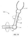
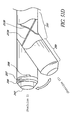
FIG. 30 is an oblique elevational view of an articulating arm stent delivery/retrieval apparatus having features and advantages in accordance with an embodiment of at least one of the inventions disclosed herein; -
FIG. 31 is a schematic and partial sectional view of a portion of an eye and illustrating an implantation of a glaucoma stent using a delivery apparatus extending through the anterior chamber of the eye; -
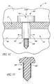
FIG. 32 is a schematic and partial sectional view of a Schlemm's canal and trabecular meshwork of an eye with another glaucoma stent extending from the anterior chamber of the eye, through the trabecular meshwork, and into a rear wall of the Schlemm's canal; -
FIG. 33 is an enlarged cross-sectional view of a distal portion of the stent illustrated inFIG. 32 ; -
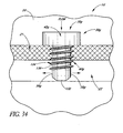
FIG. 34 is a schematic and partial sectional view of the eye ofFIG. 32 and a side elevational view of a modification of the stent illustrated inFIG. 32 ; -
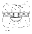
FIG. 35 is a schematic and partial sectional view of the eye illustrated inFIG. 32 , and a side elevational view of a photomodification of the stent illustrated inFIG. 32 ; -
FIG. 36 is a schematic and partial sectional view of the eye illustrated inFIG, 32 , and a side elevational view of another modification of the stent ofFIG. 32 ; -
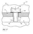
FIG. 37 is a schematic and partial sectional view of the eye illustrated inFIG. 32 , and a side elevational view of a further modification of the implant illustrated inFIG. 32 ; -
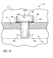
FIG. 38 is a schematic and partial sectional view of the eye illustrated inFIG. 32 and a side elevational view of another modification of the stent illustrated inFIG. 32 ; -
FIG. 39 is a schematic and partial sectional view of the eye illustrated inFIG. 32 , and a side elevational view of the further modification of the implant illustrated inFIG. 32 ; -
FIG. 40 is a schematic and partial sectional view of the eye illustrated inFIG. 32 , and a side elevational view of yet another modification of the stent illustrated inFIG. 32 ; -
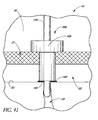
FIG. 41 is a schematic and partial sectional view of an eye and the side elevational view of yet another modification of the stent illustrated inFIG. 32 ; -
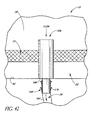
FIG. 42 is a schematic and partial sectional view of the eye illustrated inFIG. 32 , and a side elevational view of yet another modification of the implant illustrated inFIG. 32 ; -
FIG. 43 is an enlarged schematic and partial cross-sectional view of an anterior chamber angle of an eye having a valve stent implanted therein; -
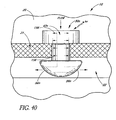
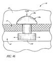
FIG. 44 is an enlarged cross-sectional view of an anterior chamber angle of an eye including an osmotic membrane device implanted therein; -
FIG. 45 is an enlarged cross-sectional view of an anterior chamber angle of an eye illustrating an implantation of a glaucoma stent using an ab externo procedure; -
FIG. 46 is a schematic and partial sectional view of the eye illustrated inFIG. 32 and a side elevational view of another modification of the implant illustrated inFIG. 32 ; -
FIG. 47 is an enlarged schematic and partial sectional view of the eye illustrated inFIG. 32 and including a drug release device implanted therein; -
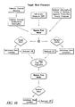
FIG. 48 is a flow diagram illustrating a method for treating glaucoma; -
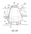
FIG. 49A is an enlarged schematic illustration showing an anterior chamber, trabecular meshwork and a Schlemm's canal of an eye and an oblique elevational view of yet another modification of the stent illustrated inFIG. 32 ; -
FIG. 49B is an oblique elevational view of a modification of the stent illustrated inFIG. 49A ; -
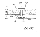
FIG. 49C is a side elevational view of another modification of the stent illustrated inFIG. 49A ; -
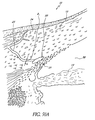
FIG. 50A is a cross-sectional view of the eye portion showing anatomically the trabecular meshwork, Schlemm's canal and one collector duct; -
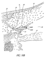
FIG. 50B is a cross-sectional view ofFIG. 50A with a portion of a stent mechanically inserted into one of the collector ducts; -
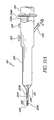
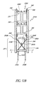
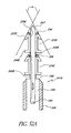
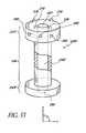
FIG. 51A is a side elevational view of a stent delivery applicator with a steerable distal section for multiple stent deployment; -
FIG. 51B is a schematic and partial sectional view of the distal section of the stent delivery applicator ofFIG. 51A ; -
FIG. 51C is a cross-sectional view, section 1-1 ofFIG. 51B ; -
FIG. 51D is an oblique side elevational view of the steerable section of the delivery applicator illustrated inFIG. 51A and including an optional ultrasonically enabled distal end; -
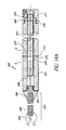
FIG. 52A is a partial sectional and side elevational view of a distal section of a modification of the stent delivery applicator illustrated inFIG. 51A ; -
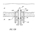
FIG. 52B is a partial sectional and side elevational view of a distal section of the stent delivery applicator illustrated inFIG. 51A having been inserted through a trabecular meshwork with the stent disposed within the distal section; -
FIG. 52C is a partial sectional and side elevational view of a distal section of the stent delivery applicator illustrated inFIG. 51A having been inserted through a trabecular meshwork and after the sheath of the distal portion has been withdrawn; -
FIG. 52D is a partial sectional and side elevational view of a distal section of the stent delivery applicator illustrated inFIG. 51A having been inserted through a trabecular meshwork, and after the sheath and a cutting member have been withdrawn; -
FIG. 53 is an oblique side elevational and partial sectional view of a further modification of the stent illustrated inFIG. 32 ; -
FIG. 54A is a sectional view of yet another modification of the stent delivery applicator illustrated inFIG. 51A ; -
FIG. 54B is an enlarged sectional view of a distal end of the applicator illustrated inFIG. 54A and including two implants disposed over a trocar of the device, this portion being identified by the circle 2-2 inFIG. 54A ; -
FIG. 54C is a sectional view of the applicator device taken along section line 3-3 ofFIG. 54A . - The embodiments described herein relate particularly to surgical and therapeutic treatment of glaucoma through reduction of intraocular pressure and/or stimulation of the trabecular meshwork tissue. While the description sets forth various embodiment-specific details, it will be appreciated that the description is illustrative only and should not be construed in any way as limiting the invention. Furthermore, various applications of the inventions disclosed herein, and modifications thereto, which may occur to those who are skilled in the art, are also encompassed by the general concepts described herein. Some of the implants described are not encompassed by the scope of the claims.
-
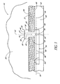
FIG. 1 is a cross-sectional view of aneye 10.FIG. 2 is an enlarged sectional view of the eye showing the relative anatomical locations of atrabecular meshwork 21, ananterior chamber 20, and a Schlemm'scanal 22. Asclera 11 is a thick collagenous tissue which covers theentire eye 10 except a portion which is covered by acornea 12, - With reference to
FIGS. 1 and2 , thecornea 12 is a thin transparent tissue that focuses and transmits light into the eye and through apupil 14, which is a circular hole in the center of an iris 13 (colored portion of the eye). Thecornea 12 merges into the sclera 11 at a juncture referred to as alimbus 15. Aciliary body 16 extends along the interior of thesclera 11 and is coextensive with achoroid 17. Thechoroid 17 is a vascular layer of theeye 10, located between the sclera 11 and aretina 18. Anoptic nerve 19 transmits visual information to the brain and is the anatomic structure that is progressively destroyed by glaucoma. - With continued reference to
FIGS. 1 and2 , theanterior chamber 20 of theeye 10, which is bound anteriorly by thecornea 12 and posteriorly by theiris 13 and alens 26, is filled with aqueous humor (hereinafter referred to as "aqueous"). Aqueous is produced primarily by theciliary body 16, then moves anteriorly through thepupil 14 and reaches ananterior chamber angle 25, formed between theiris 13 and thecornea 12. - As best illustrated by the drawing of
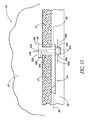
FIG. 2 , in a normal eye, aqueous is removed from theanterior chamber 20 through thetrabecular meshwork 21. Aqueous passes through thetrabecular meshwork 21 into Schlemm'scanal 22 and thereafter through a plurality of collector ducts andaqueous veins 23, which merge with blood-carrying veins, and into systemic venous circulation. Intraocular pressure is maintained by an intricate balance between secretion and outflow of aqueous in the manner described above. Glaucoma is, in most cases, characterized by an excessive buildup of aqueous in theanterior chamber 20 which leads to an increase in intraocular pressure. Fluids are relatively incompressible, and thus intraocular pressure is distributed relatively uniformly throughout theeye 10. - As shown in
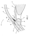
FIG. 2 , thetrabecular meshwork 21 is adjacent a small portion of thesclera 11. Exterior to thesclera 11 is aconjunctiva 24. Traditional procedures that create a hole or opening for implanting a device through the tissues of theconjunctiva 24 andsclera 11 involve extensive surgery, as compared to surgery for implanting a device, as described herein, which ultimately resides entirely within the confines of thesclera 11 andcornea 12. Atrabecular stent 229 can be placed bypassing thetrabecular meshwork 21 with aproximal terminal 227 exposed toanterior chamber 20 and adistal terminal 228 exposed to Schlemm'scanal 22. -
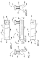
FIG. 3 schematically illustrates the use of one embodiment of atrabecular stenting device 30 for establishing an outflow pathway, passing through thetrabecular meshwork 21, described in greater detail below.FIGS. 4-9 are different views of thestent 30. Advantageously, and as discussed in further detail later herein, the self-trephining-stent allows a one-step procedure to make an incision in thetrabecular mesh 21 and place the stent orimplant 30 at the desired or predetermined position within theeye 10. Desirably, this facilitates and simplifies the overall surgical procedure. - In the illustrated embodiment of
FIGS. 3-9 , the shunt orstent 30 generally comprises an inlet portion or "snorkel" 32 and a main body portion orblade 34. Thesnorkel 32 andblade 34 are mechanically connected to or in mechanical communication with one another. A generallylongitudinal axis 36 extends along thestent 30 and/or thebody portion 34. - In the illustrated embodiment of
FIGS. 3-9 , thestent 30 comprises an integral unit. In modified embodiments, thestent 30 may comprise an assembly of individual pieces or components. For example, thestent 30 may comprise an assembly of thesnorkel 32 andblade 34. - In the illustrated embodiment of
FIGS. 3-9 , thesnorkel 32 is in the form of a generally elongate tubular member and generally comprises an upper seat, head orcap portion 38, ashank portion 40 and a lumen orpassage 42 extending therethrough. Theseat 38 is mechanically connected to or in mechanical communication with theshank 40 which is also mechanically connected to or in mechanical communication with theblade 34.longitudinal axis 43 extends along thesnorkel 32 and/or thelumen 42. ' - In the illustrated embodiment of
FIGS. 3-9 , theseat 38 is generally circular in shape and has anupper surface 44 and alower surface 46 which, as shown inFIG. 3 , abuts or rests against thetrabecular meshwork 21 to stabilize theglaucoma stent 30 within theeye 10. In modified embodiments, theseat 38 may efficaciously be shaped in other suitable manners, as required or desired, giving due consideration to the goals of stabilizing theglaucoma stent 30 within theeye 10 and/or of achieving one or more of the benefits and advantages as taught or suggested herein. For example, theseat 38 may be shaped in other polygonal or non-polygonal shapes and/or comprise one or more ridges which extend radially outwards, among other suitable retention devices. - In the illustrated embodiment of
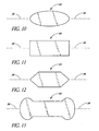
FIGS. 3-9 , and as best seen in the top view ofFIG. 5 , the seattop surface 44 comprises fiducial marks orindicia 48. These marks orindicia 48 facilitate and ensure proper orientation and alignment of thestent 30 when implanted in theeye 10. The marks orindicia 48 may comprise visual differentiation means such as color contrast or be in the form of ribs, grooves, or the like. Alternatively, or in addition, themarks 48 may provide tactile sensory feedback to the surgeon by incorporating a radiopaque detectable or ultrasound imaginable substrate at about themark 48. Also, theseat 38 and/or the seattop surface 44 may be configured in predetermined shapes aligned with theblade 34 and/orlongitudinal axis 36 to provide for proper orientation of thestent device 30 within theeye 10. For example, the seattop surface 44 may be oval or ellipsoidal (FIG. 10 ), rectangular (FIG. 11 ), hexagonal (FIG. 12 ), among other suitable shapes (e.g.FIG.13 ). - In the illustrated embodiment of
FIGS. 3-9 , and as indicated above, theseat bottom surface 46 abuts or rests against thetrabecular meshwork 21 to stabilize and retain theglaucoma stent 30 within theeye 10. For stabilization purposes, theseat bottom surface 46 may comprise a studded surface, a ribbed surface, a surface with pillars, a textured surface, or the like. - In the illustrated embodiment of
FIGS. 3-9 , thesnorkel shank 40 is generally cylindrical in shape. With thestent 30 implanted, as shown inFIG. 3 , theshank 40 is generally positioned in an incision orcavity 50 formed in thetrabecular meshwork 21 by the self-trephiningstent 30. Advantageously, and as discussed further below, this single step of forming thecavity 50 by thestent 30 itself and placing thestent 30 in the desired position facilitates and expedites the overall surgical procedure. In modified embodiments, thesnorkel shank 40 may efficaciously be shaped in other suitable manners, as required or desired. For example, theshank 40 may be in the shape of other polygonal or non-polygonal shapes, such as, oval, ellipsoidal, and the like. - In the illustrated embodiment of
FIGS. 3-9 , and as best seen inFIG. 3 , theshank 40 has anouter surface 52 in contact with thetrabecular meshwork 21 surrounding thecavity 50. For stabilization purposes, the shankouter surface 52 may comprise a studded surface, a ribbed surface, a surface with pillars, a textured surface, or the like. - In the illustrated embodiment of
FIGS. 3-9 , thesnorkel lumen 42 has an inlet port, opening ororifice 54 at the seattop surface 44 and an outlet port, opening ororifice 56 at the junction of theshank 40 andblade 34. Thelumen 42 is generally cylindrical in shape, that is, it has a generally circular cross-section, and itsports lumen 42 andports lumen 42 and/or one or bothports lumen 42 may have a tapered or stepped configuration. - Referring in particular to
FIG. 3 , aqueous from theanterior chamber 20 flows into thelumen 42 through the inlet port 54 (as generally indicated by arrow 58) and out of theoutlet port 56 and into Schlemm's canal 22 (as generally indicated by arrows 60) to lower and/or balance the intraocular pressure (IOP). In another embodiment, as discussed in further detail below, one or more of the outlet ports may be configured to face in the general direction of the stentlongitudinal axis 36. In modified embodiments, thesnorkel 32 may comprise more than one lumen, as needed or desired, to facilitate multiple aqueous outflow transportation into Schlemm'scanal 22. - In the illustrated embodiment of
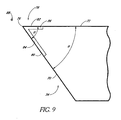
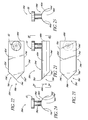
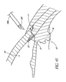
FIGS. 3-9 , the bladelongitudinal axis 36 and the snorkellongitudinal axis 43 are generally perpendicular to one another. Stated differently, the projections of theaxes axes longitudinal axis 36 and the snorkellongitudinal axis 43 may intersect one another or may be offset from one another. - In the illustrated embodiment of
FIGS. 3-9 , the main body portion orblade 34 is a generally curved elongated sheet- or plate-like structure with an uppercurved surface 62 and a lowercurved surface 64 which defines a trough oropen face channel 66. The perimeter of theblade 34 is generally defined by a curvedproximal edge 68 proximate to thesnorkel 32, a curveddistal edge 70 spaced from theproximal edge 68 by a pair of generally straightlateral edges lateral edge 72 extends beyond the secondlateral edge 74 and intersects with thedistal edge 70 at adistal-most point 76 of theblade 34. Preferably, theblade 34 defines ablade cutting tip 78. - In the illustrated embodiment of
FIGS. 3-9 , and as shown in the enlarged view ofFIG. 9 , the cuttingtip 78 comprises afirst cutting edge 80 on thedistal edge 70 and asecond cutting edge 82 on thelateral edge 72. The cutting edges 80, 82 preferably extend from thedistal-most point 76 of theblade 34 and comprise at least a respective portion of thedistal edge 70 andlateral edge 72. Therespective cutting edges surfaces distal edge 70 andlateral edge 72 are dull or rounded. In one embodiment, thetip 78 proximate to thedistal-most end 76 is curved slightly inwards, as indicated generally by thearrow 88 inFIG. 5 and arrow 88 (pointed perpendicular and into the plane of the paper) inFIG. 9 , relative to the adjacent curvature of theblade 34. - In modified embodiments, suitable cutting edges may be provided on selected portions of one or more selected blade edges 68, 70, 72, 74 with efficacy, as needed or desired, giving due consideration to the goals of providing suitable cutting means on the
stent 30 for effectively cutting through the trabecular meshwork 21 (FIG. 3 ) and/or of achieving one or more of the benefits and advantages as taught or suggested herein. - Referring in particular to
FIG. 9 , in one embodiment, the ratio between the lengths of the cutting edges 80, 82 is about 2:1. In another embodiment, the ratio between the lengths of the cutting edges 80, 82 is about 1:1. In yet another embodiment, the ratio between the lengths of the cutting edges 80, 82 is about 1:2. In modified embodiments, the lengths of the cutting edges 80, 82 may be efficaciously selected in other manners, as required or desired, giving due consideration to the goals of providing suitable cutting means on thestent 30 for effectively cutting through the trabecular meshwork 21 (FIG. 3 ) and/or of achieving one or more of the benefits and advantages as taught or suggested herein. - Still referring in particular to
FIG. 9 , in one embodiment, the ratio between the lengths of the cutting edges 80, 82 is in the range from about 2:1 to about 1:2. In another embodiment, the ratio between the lengths of the cutting edges 80, 82 is in the range from about 5:1 to about 1:5. In yet another embodiment, the ratio between the lengths of the cutting edges 80, 82 is in the range from about 10:1 to about 1:10. In modified embodiments, the lengths of the cutting edges 80, 82 may be efficaciously selected in other manners, as required or desired, giving due consideration to the goals of providing suitable cutting means on thestent 30 for effectively cutting through the trabecular meshwork 21 (FIG. 3 ) and/or of achieving one or more of the benefits and advantages as taught or suggested herein. - As shown in the top view of
FIG. 9 , the cutting edge 80 (and/or the distal end 70) and the cutting edge 82 (and/or the lateral edge 72) intersect at an angle θ. Stated differently, θ is the angle between the projections of the cutting edge 80 (and/or the distal end 70) and the cutting edge 82 (and/or the lateral edge 72) on a common plane which is not perpendicular to either of these edges. - Referring to in particular to
FIG. 9 , in one embodiment, the angle θ is about 50°. In another embodiment, the angle θ is in the range from about 40° to about 60°. In yet another embodiment, the angle θ is in the range from about 30° to about 70°. In modified embodiments, the angle θ may be efficaciously selected in other manners, as required or desired, giving due consideration to the goals of providing suitable cutting means on thestent 30 for effectively cutting through the trabecular meshwork 21 (FIG. 3 ) and/or of achieving one or more of the benefits and advantages as taught or suggested herein. - The
stent 30 of the embodiments disclosed herein can be dimensioned in a wide variety of manners. Referring in particular toFIG. 3 , the depth of Schlemm'scanal 22 is typically about less than 400 microns (µm). Accordingly, thestunt blade 34 is dimensioned so that the height of the blade 34 (referred to as H41 inFIG. 4 ) is typically less than about 400 µm. Thesnorkel shank 40 is dimensioned so that it has a length (referred to as L41 inFIG. 4 ) typically in the range from about 150 µm to about 400 µm which is roughly the typical range of the thickness of thetrabecular meshwork 21. - Of course, as the skilled artisan will appreciate, that with the
stent 30 implanted, theblade 34 may rest at any suitable position within Schlemm'scanal 22. For example, theblade 34 may be adjacent to afront wall 90 of Schlemm's canal 22 (as shown inFIG. 3 ), or adjacent to aback wall 92 of Schlemm'scanal 22, or at some intermediate location therebetween, as needed or desired. Also, thesnorkel shank 40 may extend into Schlemm'scanal 22. The length of thesnorkel shank 40 and/or the dimensions of theblade 34 may be efficaciously adjusted to achieve the desired implant positioning. - The trabecular stenting device 30 (
FIGS. 3-9 ) of the exemplary embodiment may be manufactured or fabricated by a wide variety of techniques. These include, without limitation, molding, thermo-forming, or other micro-machining techniques, among other suitable techniques. - The
trabecular stenting device 30 preferably comprises a biocompatible material such that inflammation arising due to irritation between the outer surface of thedevice 30 and the surrounding tissue is minimized. Biocompatible materials which may be used for thedevice 30 preferably include, but are not limited to, titanium, titanium alloys, medical grade silicone, e.g., Silastic™, available from Dow Coming Corporation of Midland, Michigan; and polyurethane, e.g., Pellethane™, also available from Dow Corning Corporation. - In other embodiments, the
stent device 30 may comprise other types of biocompatible material, such as, by way of example, polyvinyl alcohol, polyvinyl pyrolidone, collagen, heparinized collagen, polytetrafluoroethylene, expanded polytetrafluoroethylene, fluorinated polymer, fluorinated elastomer, flexible fused silica, polyolefin, polyester, polysilicon, and/or a mixture of the aforementioned biocompatible materials, and the like. In still other embodiments, composite biocompatible material may be used, wherein a surface material may be used in addition to one or more of the aforementioned materials. For example, such a surface material may include polytetrafluoroethylene (PTFE) (such as Teflon™), polyimide, hydrogel, heparin, therapeutic drugs (such as beta-adrenergic antagonists and other anti-glaucoma drugs, or antibiotics), and the like. - In an exemplary embodiment of the trabecular meshwork surgery, the patient is placed in the supine position, prepped, draped and anesthetized as necessary. A small (less than about 1 mm) incision, which may be self sealing can then be made through the
cornea 12. The corneal incision can be made in a number of ways, for example, by using a micro-knife, among other tools. - An applicator or delivery apparatus is used to advance the
glaucoma stent 30 through the corneal incision and to thetrabecular meshwork 21. Some embodiments of such a delivery apparatus are disclosed in copendingU.S. Application No. 101101,548, filed March 18, 2002 , entitled APPLICATOR AND METHODS FOR PLACING A TRABECULAR SHUNT FOR GLAUCOMA TREATMENT, andU.S. Provisional Application No. 60/276,609, filed March 16, 2001 - With the
device 30 held by the delivery apparatus, theblade 34 of thedevice 30 is used to cut and/or displace the material of thetrabecular meshwork 21. Thesnorkel shank 40 can also facilitate in removal of this material during implantation. The delivery apparatus is withdrawn once thedevice 30 has been implanted in theeye 10. As shown inFIG. 3 , thesnorkel seat 38 can rest on atop surface 94 of thetrabecular meshwork 21 with thesnorkel shank 40 extending through the cavity 50 (created by the device 30) in thetrabecular meshwork 21, and with theblade 34 extending inside Schlemm'scanal 22. - Advantageously, the embodiments of the self-trephining
stent device 30 allow for a "one-step" procedure to make an incision in the trabecular meshwork and to implant the stent in the proper orientation and alignment within the eye to allow outflow of aqueous from the anterior chamber through the stent and into Schlemm's canal to lower and/or balance the intraocular pressure (IOP). Desirably, this provides for a faster, safer, and less expensive surgical procedure. - Many complications can arise in trabecular meshwork surgeries, wherein a knife is first used to create an incision in the trabecular meshwork, followed by removal of the knife and subsequent installation of the stent. For instance, the knife may cause some bleeding which clouds up the surgical site. This may require more effort and time to clean the surgical site prior to placement of the stent. Moreover, this may cause the intraocular pressure (IOP) to rise or to fall undesirably. Thus, undesirably, such a multiple step procedure may demand crisis management which slows down the surgery, makes it less safe, and more expensive.
-
FIG. 14 is a simplified partial view of aneye 10 illustrating the implantation of a self-trephiningglaucoma stent device 30a having features and advantages in accordance with one embodiment. Thestent 30a is generally similar to thestent 30 ofFIGS. 3-9 except that itssnorkel 32a comprises a longer shank 40a which extends into Schlemm'scanal 22 and alumen 42a which bifurcates into twooutput channels 45a. - In the illustrated embodiment of
FIG. 14 , the shank 40a terminates at theblade 34. Aqueous flows from theanterior chamber 20 into thelumen 42a through aninlet port 54a (as generally indicated byarrow 58a). Aqueous then flows through theoutput channels 45a and out ofrespective outlet ports 56a and into Schlemm's canal 22 (as generally indicated byarrows 60a). Theoutlet channels 45a extend radially outwards in generally opposed directions and theoutlet ports 56a are configured to face in the general direction of the stentlongitudinal axis 36 so that they open into Schlemm'scanal 22 and are in proper orientation to allow aqueous outflow into Schlemm'scanal 22 for lowering and/or balancing the intraocular pressure (IOP). As indicated above, fiducial marks or indicia and/or predetermined shapes of thesnorkel seat 38 allow for proper orientation of theblade 34 and also theoutput channels 45a andrespective ports 56a within Schlemm's canal. - In the illustrated embodiment of
FIG. 14 , twooutflow channels 45a are provided. In another embodiment, only oneoutflow channel 45a is provided. In yet another embodiment, more than twooutflow channels 45a are provided. In modified embodiments, thelumen 42a may extend all the way through to theblade 34 and provide an outlet port as discussed above with reference to the embodiment ofFIGS. 3-9 . -
FIG. 15 is a simplified partial view of aneye 10 illustrating the implantation of a self-trephiningglaucoma stent device 30b having features and advantages in accordance with one embodiment. Thestent 30b is generally similar to thestent 30 ofFIGS. 3-9 except that itssnorkel 32b comprises alonger shank 40b which extends into Schlemm'scanal 22 and alumen 42b which bifurcates into twooutput channels 45b. - In the illustrated embodiment of
FIG. 15 , theshank 40b extends through theblade 34. Aqueous flows from theanterior chamber 20 into thelumen 42b through aninlet port 54b (as generally indicated byarrow 58b). Aqueous then flows through theoutput channels 45b and out ofrespective outlet ports 56b and into Schlemm's canal 22 (as generally indicated byarrows 60b). Theoutlet channels 45b extend radially outwards in generally opposed directions and theoutlet ports 56b are configured to face in the general direction of the stentlongitudinal axis 36 so that they open into Schlemm'scanal 22 and are in proper orientation to allow aqueous outflow into Schlemm'scanal 22 for lowering and/or balancing the intraocular pressure (IOP). As indicated above, fiducial marks or indicia and/or predetermined shapes of thesnorkel seat 38 allow for proper orientation of theblade 34 and also theoutput channels 45b andrespective ports 56b within Schlemm's canal. - In the illustrated embodiment of
FIG. 15 , twooutflow channels 45b are provided. In another embodiment, only oneoutflow channel 45b is provided. In yet another embodiment, more than twooutflow channels 45b are provided. In modified embodiments, thelumen 42b may extend all the way through to theblade 34 and provide an outlet port as discussed above with reference to the embodiment ofFIGS. 3-9 . -
FIGS. 16-20 show different views of a self-trephiningglaucoma stent device 30c having features and advantages in accordance with one embodiment. Thestent 30c is generally similar to thestent 30 ofFIGS. 3-9 except that it has a modified blade configuration. Thestent 30c comprises ablade 34c which is a generally curved elongated sheet- or plate-like structure with an uppercurved surface 62c and a lowercurved surface 64c which defines a trough oropen face channel 66c. The perimeter of theblade 34c is generally defined by a curvedproximal edge 68c proximate to thesnorkel 32, a curveddistal edge 70c spaced from theproximal edge 68c by a pair of generally straightlateral edges - In the illustrated embodiment of
FIGS. 16-20 , theblade 34c comprises acutting tip 78c. The cuttingtip 78c preferably includes cutting edges formed on selected portions of thedistal edge 70c and adjacent portions of thelateral edges snorkel 32. The cutting edges are sharp edges of beveled or tapered surfaces as discussed above in reference toFIG. 9 . The embodiment ofFIGS. 16-20 may be efficaciously modified to incorporate the snorkel configuration of the embodiments ofFIGS. 14 and15 . -
FIGS. 21-25 show different views of a self-trephiningglaucoma stent device 30d having features and advantages in accordance with one embodiment. Thestent 30d is generally similar to thestent 30 ofFIGS. 3-9 except that it has a modified blade configuration. Thestent 30d comprises ablade 34d which is a generally curved elongated sheet- or plate-like structure with an uppercurved surface 62d and a lowercurved surface 64d which defines a trough oropen face channel 66d. The perimeter of theblade 34d is generally defined by a curvedproximal edge 68d proximate to thesnorkel 32, a pair of inwardly converging curveddistal edges 70d', 70d" spaced from theproximal edge 68d by a pair of generally straight respectivelateral edges distal edges 70d', 70d" intersect at adistal-most point 76d of theblade 34d proximate ablade cutting tip 78d. - In the illustrated embodiment of
FIGS. 21-25 , the cuttingtip 78d preferably includes cutting edges formed on thedistal edges 70d', 70d" and extending from thedistal-most point 76d of theblade 34d. In one embodiment, the cutting edges extend along only a portion of respectivedistal edges 70d', 70d." In another embodiment, the cutting edges extend along substantially the entire length of respectivedistal edges 70d', 70d." In yet another embodiment, at least portions of thelateral edges distal edges 70d', 70d" have cutting edges. In a further embodiment, thetip 78d proximate to thedistal-most end 76d is curved slightly inwards, as indicated generally by the arrow 88d inFIG. 21 and arrow 88d (pointed perpendicular and into the plane of the paper) inFIG. 22 , relative to the adjacent curvature of theblade 34d, - In the embodiment of
FIGS. 21-25 , the cutting edges are sharp edges of beveled or tapered surfaces as discussed above in reference toFIG. 9 . The embodiment ofFIGS. 21-25 may be efficaciously modified to incorporate the snorkel configuration of the embodiments ofFIGS. 14 and15 . -
FIGS. 26-28 show different views of a self-trephiningglaucoma stent device 30e having features and advantages in accordance with one embodiment. Thestent device 30e generally comprises asnorkel 32e mechanically connected to or in mechanical communication with a blade or cutting tip 34e. Thesnorkel 32e has a seat, head orcap portion 38e mechanically connected to or in mechanical communication with ashank 40e, as discussed above. Theshank 40e has a distal end orbase 47e. Thesnorkel 32e further has alumen 42e which bifurcates into a pair ofoutlet channels 45e, as discussed above in connection withFIGS. 14 and15 . Other lumen and inlet and outlet port configurations as taught or suggested herein may also be efficaciously used, as needed or desired. - In the illustrated embodiment of
FIGS. 26-28 , the blade 34e extends downwardly and outwardly from the shankdistal end 47e. The blade 34e is angled relative to a generallylongitudinal axis 43e of thesnorkel 32e, as best seen inFIGS. 27 and 28 . The blade 34e has adistal-most point 76e. The blade or cutting tip 34e has a pair ofside edges 70e', 70e," including cutting edges, terminating at thedistal-most point 76e, as best seen inFIG. 26 . In one embodiment, the cutting edges are sharp edges of beveled or tapered surfaces as discussed above in reference toFIG. 9 . - Referring to
FIGS. 26-28 , in one embodiment, the blade 34e includes cutting edges formed on theedges 70e', 70e" and extending from thedistal-most point 76e of theblade 34d. In one embodiment, the cutting edges extend along only a portion of respectivedistal edges 70e', 70e." In another embodiment, the cutting edges extend along substantially the entire length of respectivedistal edges 70e', 70e." In yet another embodiment, the blade or cutting tip 34e comprises a bent tip of needle, for example, a 30 gauge needle. - In general, any of the blade configurations disclosed herein may be used in conjunction with any of the snorkel configurations disclosed herein or incorporated by reference herein to provide a self-trephining glaucoma stent device for making an incision in the trabecular meshwork for receiving the corresponding snorkel to provide a pathway for aqueous outflow from the eye anterior chamber to Schlemm's canal, thereby effectively lowering and/or balancing the intraocular pressure (IOP). The self-trephining ability of the device, advantageously, allows for a "one-step" procedure in which the incision and placement of the snorkel are accomplished by a single device and operation. In any of the embodiments, fiducial markings or indicia, and/or preselected configuration of the snorkel seat, and/or positioning of the stent device in a preloaded applicator may be used for proper orientation and alignment of the device during implantation.
- In many cases, a surgeon works from a temporal incision when performing cataract or goniometry surgery.
FIG. 29 illustrates a temporal implant procedure, wherein a delivery apparatus or "applicator" 100 having acurved tip 102 is used to deliver astent 30 to atemporal side 27 of theeye 10. Anincision 28 is made in thecornea 10, as discussed above. Theapparatus 100 is then used to introduce thestent 30 through theincision 28 and implant it within theeye 10. - Still referring in particular to
FIG. 29 , in one embodiment, a similarly curved instrument would be used to make the incision through thetrabecular meshwork 21. In other embodiments, a self-trephiningstent device 30 may be used to make this incision through thetrabecular meshwork 21, as discussed above. The temporal implantation procedure illustrated inFIG. 29 may be employed with the any of the various stent embodiments taught or suggested herein. -
FIG. 30 illustrates one embodiment of an apparatus comprising an articulating stent applicator orretrieval device 100a. In this embodiment, aproximal arm 106 is attached to adistal arm 108 at a joint 112. This joint 112 is movable such that an angle formed between theproximal arm 106 and thedistal arm 108 can change. One ormore claws 114 can extend from thedistal arm 108, in the case of a stent retrieval device. Similarly, this articulation mechanism may be used for the trabecular stent applicator, and thus the articulating applicator orretrieval device 100a may be either an applicator for the trabecular stent, a retrieval device, or both, in various embodiments. The embodiment ofFIG. 30 may be employed with the any of the various stent embodiments taught or suggested herein. -
FIG. 31 shows another illustrative method for placing any of the various stent embodiments taught or suggested herein at the implant site within theeye 10. A delivery apparatus 100b generally comprises asyringe portion 116 and acannula portion 118. The distal section of thecannula 118 has at least one irrigatinghole 120 and adistal space 122 for holding thestent device 30. Theproximal end 124 of the lumen of thedistal space 122 is sealed from the remaining lumen of thecannula portion 118. The delivery apparatus ofFIG. 30 may be employed with the any of the various stent embodiments taught or suggested herein. - In one aspect of the invention, a delivery apparatus (or "applicator") is used for placing a trabecular stent through a trabecular meshwork of an eye. Certain embodiments of such a delivery apparatus are disclosed in copending
U.S. Application No. 10/101,548, filed March 18, 2002 U.S. Provisional Application No. 60/276,609, filed March 16, 2001 - The stent has an inlet section and an outlet section. The delivery apparatus includes a handpiece, an elongate tip, a holder and an actuator. The handpiece has a distal end and a proximal end. The elongate tip is connected to the distal end of the handpiece. The elongate tip has a distal portion and is configured to be placed through a corneal incision and into an anterior chamber of the eye. The holder is attached to the distal portion of the elongate tip. The holder is configured to hold and release the inlet section of the trabecular stent. The actuator is on the handpiece and actuates the holder to release the inlet section of the trabecular stent from the holder. When the trabecular stent is deployed from the delivery apparatus into the eye, the outlet section is positioned in substantially opposite directions inside Schlemm's canal. In one embodiment, a deployment mechanism within the delivery apparatus includes a push-pull type plunger.
- In some embodiments, the holder comprises a clamp. In some embodiments, the apparatus further comprises a spring within the handpiece that is configured to be loaded when the stent is being held by the holder, the spring being at least partially unloaded upon actuating the actuator, allowing for release of the stent from the holder.
- In various embodiments, the clamp comprises a plurality of claws configured to exert a clamping force onto the inlet section of the stent. The holder may also comprise a plurality of flanges.
- In some embodiments, the distal portion of the elongate tip is made of a flexible material. This can be a flexible wire. The distal portion can have a deflection range, preferably of about 45 degrees from the long axis of the handpiece.
- The delivery apparatus can further comprise an irrigation port in the elongate tip.
- Some aspects include a method of placing a trabecular stent through a trabecular meshwork of an eye, the stent having an inlet section and an outlet section, including advancing a delivery apparatus holding the trabecular stent through an anterior chamber of the eye and into the trabecular meshwork, placing part of the stent through the trabecular meshwork and into a Schlemm's canal of the eye; and releasing the stent from the delivery apparatus.
- In various embodiments, the method includes using a delivery apparatus that comprises a handpiece having a distal end and a proximal end; an elongate tip connected to the distal end of the handpiece, the elongate tip having a distal portion and being configured to be placed through a corneal incision and into an anterior chamber of the eye; a holder attached to the distal portion of the elongate tip, the holder configured to hold and release the inlet section of the trabecular stent; and an actuator on the handpiece that actuates the holder to release the inlet section of the trabecular stent from the holder.
- In one aspect, the trabecular stent is removably attached to a delivery apparatus (also known as "applicator"). When the trabecular stent is deployed from the delivery apparatus into the eye, the outlet section is positioned in substantially opposite directions inside Schlemm's canal. In one embodiment, a deployment mechanism within the delivery apparatus includes a push-pull type plunger, in some embodiments, the delivery applicator may be a guidewire, an expandable basket, an inflatable balloon, or the like,
- Screw/Barb Anchored Stent
-
FIGS. 32 and 33 illustrate aglaucoma stent device 30f having features and advantages in accordance with one embodiment. This embodiment of thetrabecular stent 30f includes a barbed or threaded screw-like extension or pin 126 withbarbs 128 for anchoring. Thebarbed pin 126 extends from a distal orbase portion 130 of thestent 30f. - In use, the
stent 30f (FIG. 32 ) is advanced through thetrabecular meshwork 21 and across Schlemm'scanal 22. The barbed (or threaded)extension 126 penetrates into theback wall 92 of Schlemm'scanal 22 up to the shoulder orbase 130 that then rests on theback wall 92 of thecanal 22. The combination of ashoulder 130 and abarbed pin 126 of a particular length limits the penetration depth of thebarbed pin 126 to a predetermined or preselected distance. In one embodiment, the length of thepin 126 is about 0.5 mm or less. Advantageously, this barbed configuration provides a secure anchoring of thestent 30f. As discussed above, correct orientation of thestent 30f is ensured by appropriate fiducial marks, indicia or the like and by positioning of the stent in a preloaded applicator. - Referring to
FIG. 32 , the aqueous flows from theanterior chamber 20, through thelumen 42f, then out through two side-ports 56f to be directed in both directions along Schlemm'scanal 22. Alternatively, flow could be directed in only one direction through a single side-port 56f. In other embodiments, more then twooutlet ports 56f, for example, six to eight ports (like a pin wheel configuration), may be efficaciously used, as needed or desired. - Still referring to
FIG. 32 , in one embodiment, thestent 30f is inserted through a previously made incision in thetrabecular meshwork 21. In other embodiments, thestent 30f may be combined with any of the blade configurations taught or suggested herein to provide self-trephining capability. In these cases, the incision through thetrabecular meshwork 21 is made by the self-trephining stent device which has a blade at its base or proximate to the base. - Deeply Threaded Stent
-
FIG. 34 illustrates aglaucoma stent device 30g having features and advantages in accordance with one embodiment. Thestent 30g has a head orseat 38g and a shank ormain body portion 40g with a base ordistal end 132. This embodiment of thetrabecular stent 30g includes a deep thread 134 (with threads 136) on themain body 40g of thestent 30g below thehead 38g. The threads may or may not extend all the way to thebase 132. - In use, the
stent 30g (FIG. 34 ) is advanced through themeshwork 21 through a rotating motion, as with a conventional screw. Advantageously, thedeep threads 136 provide retention and stabilization of thestent 30g in thetrabecular meshwork 21. - Referring to
FIG. 34 , the aqueous flows from theanterior chamber 20, through thelumen 42g, then out through two side-ports 56g to be directed in both directions along Schlemm'scanal 22. Alternatively, flow could be directed in only one direction through a single side-port 56g. In other embodiments, more then twooutlet ports 56g may be efficaciously used, as needed or desired. - One suitable applicator or delivery apparatus for this
stent 30g (FIG. 34 ) includes a preset rotation, for example, via a wound torsion spring or the like. The rotation is initiated by a release trigger on the applicator. A final twist of the applicator by the surgeon and observation of suitable fiducial marks, indicia or the like ensure proper alignment of theside ports 56g with Schlemm'scanal 22. - Referring to
FIG. 34 , in one embodiment, thestent 30g is inserted through a previously made incision in thetrabecular meshwork 21. In other embodiments, thestent 30g may be combined with any of the blade configurations taught or suggested herein to provide self-trephining capability. In these cases, the incision through thetrabecular meshwork 21 is made by the self-trephining stent device which has a blade at its base or proximate to the base. - Rivet Style Stent
-
FIG. 35 illustrates aglaucoma stent device 30h having features and advantages in accordance with one embodiment. The stent has a base ordistal end 138. This embodiment of thetrabecular stent 30h has a pair offlexible ribs 140. In the unused state, the ribs are initially generally straight (that is, extend in the general direction of arrow 142). - Referring to
FIG. 35 , upon insertion of thestent 30h through thetrabecular meshwork 21, theends 144 ofrespective ribs 140 of thestent 30h come to rest on theback wall 92 of Schlemm'scanal 22. Further advancement of thestent 30h causes theribs 140 to deform to the bent shape as shown in the drawing ofFIG. 35 . Theribs 140 are designed to first buckle near thebase 138 of thestent 30h. Then the buckling point moves up theribs 140 as theshank part 40h of thestent 30h is further advanced through thetrabecular meshwork 21. - The lumen 42h (
FIG. 35 ) in thestent 30h is a simple straight hole. The aqueous flows from theanterior chamber 20, through the lumen 42h, then out around theribs 140 to the collector channels further along Schlemm'scanal 22 in either direction. - Referring to
FIG. 35 , in one embodiment, thestent 30h is inserted through a previously made incision in thetrabecular meshwork 21. In other embodiments, thestent 30h may be combined with any of the blade configurations taught or suggested herein to provide self-trephining capability. In these cases, the incision through thetrabecular meshwork 21 is made by the self-trephining stent device which has a blade at its base or proximate to the base. - Grommet Style Stent
-
FIG. 36 illustrates aglaucoma stent device 30i having features and advantages in accordance with one embodiment. This embodiment of thetrabecular stent 30i includes a head or seat 38i, a taperedbase portion 146 and an intermediate narrower waist portion orshank 40i. - In use, the
stent 30i (FIG. 36 ) is advanced through thetrabecular meshwork 21 and thebase 146 is pushed into Schlemm'scanal 22. Thestent 30i is pushed slightly further, if necessary, until themeshwork 21 stretched by the taperedbase 146 relaxes back and then contracts to engage the smallerdiameter portion waist 40i of thestent 30i. Advantageously, the combination of the larger diameter head or seat 38i andbase 146 of thestent 30i constrains undesirable stent movement. As discussed above, correct orientation of thestent 30i is ensured by appropriate fiducial marks, indicia or the like and by positioning of the stent in a preloaded applicator. - Referring to
FIG. 36 , the aqueous flows from theanterior chamber 20, through the lumen 42i, then out through two side-ports 56i to be directed in both directions along Schlemm'scanal 22. Alternatively, flow could be directed in only one direction through a single side-port 56i. In other embodiments, more then twooutlet ports 56i may be efficaciously used, as needed or desired. - Still referring to
FIG. 36 , in one embodiment, thestent 30i is inserted through a previously made incision in thetrabecular meshwork 21. In other embodiments, thestent 30i may be combined with any of the blade configurations taught or suggested herein to provide self-trephining capability. In these cases, the incision through thetrabecular meshwork 21 is made by the self-trephining stent device which has a blade at its base or proximate to the base. - Biointeractive Stent
-
FIG. 37 illustrates aglaucoma stent device 30j having features and advantages in accordance with one embodiment. This embodiment of thetrabecular stent 30j utilizes a region ofbiointeractive material 148 that provides a site for thetrabecular meshwork 21 to firmly grip thestent 30j by ingrowth of the tissue into thebiointeractive material 148. As shown inFIG. 37 , preferably thebiointeractive layer 148 is applied to those surfaces of thestent 30j which would abut against or come in contact with thetrabecular meshwork 21. - In one embodiment, the biointeractive layer 148 (
FIG. 37 ) may be a region of enhanced porosity with a growth promoting chemical. In one embodiment, a type ofbio-glue 150 that dissolves over time is used to hold the stent secure during the time between insertion and sufficient ingrowth for stabilization. As discussed above, correct orientation of thestent 30j is ensured by appropriate fiducial marks, indicia or the like and by positioning of the stent in a preloaded applicator. - Referring to
FIG. 37 , the aqueous flows from theanterior chamber 20, through thelumen 42j, then out through two side-ports 56j to be directed in both directions along Schlemm'scanal 22. Alternatively, flow could be directed in only one direction through a single side-port 56j. In other embodiments, more then twooutlet ports 56j may be efficaciously used, as needed or desired. - Still referring to
FIG. 37 , in one embodiment, thestent 30j is inserted through a previously made incision in thetrabecular meshwork 21. In other embodiments, thestent 30j may be combined with any of the blade configurations taught or suggested herein to provide self-trephining capability. In these cases, the incision through thetrabecular meshwork 21 is made by the self-trephining stent device which has a blade at its base or proximate to the base. - Glued or Welded Stent
-
FIG. 38 illustrates aglaucoma stent device 30k having features and advantages in accordance with one embodiment. This embodiment of thetrabecular stent 30k is secured in place by using a permanent (non-dissolving) bio-glue 152 or a "welding" process (e.g. heat) to form aweld 152. Thestent 30k has a head orseat 38k and alower surface 46k. - The
stent 30k is advanced through thetrabecular meshwork 21 until the head orseat 38k comes to rest on thetrabecular meshwork 21, that is, the headlower surface 46k abuts against thetrabecular meshwork 21, and the glue orweld 152 is applied or formed therebetween, as shown inFIG. 38 . As discussed above, correct orientation of thestent 30k is ensured by appropriate fiducial marks, indicia or the like and by positioning of the stent in a preloaded applicator. - Referring to
FIG. 38 , the aqueous flows from theanterior chamber 20, through thelumen 42k, then out through two side-ports 56k to be directed in both directions along Schlemm'scanal 22. Alternatively, flow could be directed in only one direction through a single side-port 56k. In other embodiments, more then twooutlet ports 56k may be efficaciously used, as needed or desired. - Still referring to
FIG. 38 , in one embodiment, thestent 30k is inserted through a previously made incision in thetrabecular meshwork 21. In other embodiments, thestent 30k may be combined with any of the blade configurations taught or suggested herein to provide self-trephining capability. In these cases, the incision through thetrabecular meshwork 21 is made by the self-trephining stent device which has a blade at its base or proximate to the base. - Hydrophilic Latching Stent
-
FIG. 39 illustrates aglaucoma stent device 30m having features and advantages in accordance with one embodiment. This embodiment of thetrabecular stent 30m is fabricated from a hydrophilic material that expands with absorption of water. Desirably, this would enable thedevice 30m to be inserted through a smaller incision in thetrabecular meshwork 21. The subsequent expansion (illustrated by the smaller arrows 154) of thestent 30m would advantageously enable it to latch in place in thetrabecular meshwork 21. As discussed above, correct orientation of thestent 30m is ensured by appropriate fiducial marks, indicia or the like and by positioning of the stent in a preloaded applicator. - Referring to
FIG. 39 , the aqueous flows from theanterior chamber 20, through thelumen 42m, then out through two side-ports 56m to be directed in both directions along Schlemm'scanal 22. Alternatively, flow could be directed in only one direction through a single side-port 56m. In other embodiments, more then twooutlet ports 56m may be efficaciously used, as needed or desired. - Still referring to
FIG. 39 , in one embodiment, thestent 30m is inserted through a previously made incision in thetrabecular meshwork 21. In other embodiments, thestent 30m may be combined with any of the blade configurations taught or suggested herein to provide self-trephining capability. In these cases, the incision through thetrabecular meshwork 21 is made by the self-trephining stent device which has a blade at its base or proximate to the base. - Photodynamic Stent
-
FIG. 40 illustrates aglaucoma stent device 30n having features and advantages in accordance with one embodiment. This embodiment of thetrabecular stent 30n is fabricated from a photodynamic material that expands on exposure to light. - It is commonly known that there is a diurnal variation in the aqueous humor production by the eye --- it is higher during the day than it is at night. The
lumen 42n of thestent 30n responds to light entering the cornea during the day by expanding and allowing higher flow of aqueous through thelumen 42n and into Schlemm'scanal 22. This expansion is generally indicated by the smaller arrows 156 (FIG. 40 ) which show thelumen 42n (and ports) expanding or opening in response to light stimulus. (The light or radiation energy E is generally given by E = hv, where h is Planck's constant and v is the frequency of the light provided.) At night, in darkness, the lumen diameter decreases and reduces the flow allowed through thelumen 42n. In one embodiment, an excitation wavelength that is different from that commonly encountered is provided on an as-needed basis to provide higher flow of aqueous to Schlemm'scanal 22. - This photodynamic implementation is shown in
FIG. 40 for the self-latching style ofstent 30n, but can be efficaciously used with any of the other stent embodiments, as needed or desired. As discussed above, correct orientation of thestent 30n is ensured by appropriate fiducial marks, indicia or the like and by positioning of the stent in a preloaded applicator. - Referring to
FIG. 40 , the aqueous flows from theanterior chamber 20, through thelumen 42n, then out through two side-ports 56n to be directed in both directions along Schlemm'scanal 22. Alternatively, flow could be directed in only one direction through a single side-port 56n. In other embodiments, more then twooutlet ports 56n may be efficaciously used, as needed or desired. - Still referring to
FIG. 40 , in one embodiment, thestent 30n is inserted through a previously made incision in thetrabecular meshwork 21. In other embodiments, thestent 30n may be combined with any of the blade configurations taught or suggested herein to provide self-trephining capability. In these cases, the incision through thetrabecular meshwork 21 is made by the self-trephining stent device which has a blade at its base or proximate to the base. - Collector Channel Alignment Stent
-
FIG. 41 illustrates aglaucoma stent device 30p having features and advantages in accordance with one embodiment. This figure depicts an embodiment of astent 30p that directs aqueous from theanterior chamber 20 directly into acollector channel 29 which empties into aqueous veins. Thestent 30p has a base ordistal end 160. - In the illustrated embodiment of
FIG. 41 , aremovable alignment pin 158 is utilized to align thestent lumen 42p with thecollector channel 29. In use, thepin 158 extends through thestent lumen 42p and protrudes through thebase 160 and extends into thecollector channel 29 to center and/or align thestent 30p over thecollector channel 29. Thestent 30p is then pressed firmly against theback wall 92 of Schlemm'scanal 22. Apermanent bio-glue 162 is used between the stent base and theback wall 92 of Schlemm'scanal 22 to seat and securely hold thestent 30p in place. Once positioned, thepin 158 is withdrawn from thelumen 42p to allow the aqueous to flow directly from theanterior chamber 20 into thecollector duct 29. The collector ducts are nominally 20 to 100 micrometers (µm) in diameter and are visualized with a suitable microscopy method (such as ultrasound biomicroscopy (UBM)) or laser imaging to provide guidance for placement of thestent 30p. - Referring to
FIG. 41 , in one embodiment, thestent 30p is inserted through a previously made incision in thetrabecular meshwork 21. In other embodiments, thestent 30p may be combined with any of the blade configurations taught or suggested herein to provide self-trephining capability. In these cases, the incision through thetrabecular meshwork 21 is made by the self-trephining stent device which has a blade at its base or proximate to the base. - Barbed Stent (Anterior Chamber to Collector Channel)
-
FIG. 42 illustrates a glaucoma stent device 30q having features and advantages in accordance with one embodiment. This figure depicts an embodiment of a stent 30q that directs aqueous from theanterior chamber 20 directly into acollector channel 29 which empties into aqueous veins. The stent 30q has a base ordistal end 166 and thechannel 29 has wall(s) 164. - In the illustrated embodiment of
FIG, 42 , a barbed, small-diameter extension or pin 168 on thestent base 166 is guided into thecollector channel 29 and anchors on the wall(s) 164 of thechannel 29. Thepin 168 hasbarbs 170 which advantageously provide anchoring of the stent 30q. Thecollector ducts 29 are nominally 20 to 100 micrometers (µm) in diameter and are visualized with a suitable microscopy method (such as ultrasound biomicroscopy (UBM)) or laser imaging to provide guidance for placement of the stent. - Referring to
FIG. 42 , in one embodiment, the stent 30q is inserted through a previously made incision in thetrabecular meshwork 21. In other embodiments, the stent 30q may be combined with any of the blade configurations taught or suggested herein to provide self-trephining capability. In these cases, the incision through thetrabecular meshwork 21 is made by the self-trephining stent device which has a blade at its base or proximate to the base. - Valved Tube Stent (Anterior Chamber to Choroid)
-
FIG. 43 illustrates a valvedtube stent device 30r having features and advantages in accordance with one embodiment. This is an embodiment of astent 30r that provides a channel for flow between theanterior chamber 20 and the highlyvascular choroid 17. Clinically, thechoroid 17 can be at pressures lower than those desired for theeye 10. Therefore, thisstent 30r includes a valve with an opening pressure equal to the desired pressure difference between the choroid 17 and theanterior chamber 10 or a constriction that provide the desired pressure drop. - Osmotic Membrane (Anterior Chamber to Choroid)
-
FIG. 44 illustrates aosmotic membrane device 30s having features and advantages in accordance with one embodiment. This embodiment provides a channel for flow between theanterior chamber 20 and the highlyvascular choroid 17. Theosmotic membrane 30s is used to replace a portion of the endothelial layer of thechoroid 17. Since thechoroid 17 is highly vascular with blood vessels, the concentration of water on the choroid side is lower than in theanterior chamber 20 of theeye 10. Therefore, the osmotic gradient drives water from theanterior chamber 20 into thechoroid 17. - Clinically, the choroid 17 (
FIG. 44 ) can be at pressures lower than those desired for theeye 10. Therefore, desirably, both osmotic pressure and the physical pressure gradient are in favor of flow into thechoroid 17. Flow control is provided by proper sizing of the area of the membrane, --- the larger the membrane area is the larger the flow rate will be. This advantageously enables tailoring to tune the flow to the desired physiological rates. - Ab Externo Insertion of Stent via Small Puncture
-
FIG. 45 illustrates the implantation of astent 30t using an ab externo procedure having features and advantages in accordance with one embodiment. In the ab externo procedure ofFIG. 45 , thestent 30t is inserted into Schlemm'scanal 21 with the aid of an applicator ordelivery apparatus 100c that creates a small puncture into theeye 10 from outside. - Referring to
FIG. 45 , thestent 30t is housed in theapplicator 100c, and pushed out of theapplicator 100c once the applicator tip is in position within thetrabecular meshwork 21. Since the tissue surrounding thetrabecular meshwork 21 is optically opaque, an imaging technique, such as ultrasound biomicroscopy (UBM) or a laser imaging technique, is utilized. The imaging provides guidance for the insertion of the applicator tip and the deployment of thestent 30t. This technique can be used with a large variety of stent embodiments with slight modifications since thetrabecular meshwork 21 is punctured from the scleral side rather than the anterior chamber side in the ab externo insertion. -
FIG. 46 aglaucoma stent device 30u having features and advantages in accordance with a modified embodiment, This grommet-style stent 30u for ab externo insertion is a modification of the embodiment ofFIG. 36 . In the embodiment ofFIG. 46 , the upper part orhead 38u is tapered while the lower part orbase 172 is flat, as opposed to the embodiment ofFIG. 36 . Thestent 30u is inserted from the outside of theeye 10 through a puncture in the sclera. Many of the other embodiments of stents taught or suggested herein can be modified for similar implantation. - This ultra
microscopic device 30u (FIG. 46 ) can be used with (1) a targeting Lasik-type laser, or with (2) contact on eyes or with (3) combined ultrasound microscope or (4) other device inserter handpiece. - Targeted Drug Delivery to the Trabecular Meshwork
-
FIG. 47 illustrates a targeteddrug delivery implant 30v having features and advantages in accordance with one embodiment. This drawing is a depiction of a targeted drug delivery concept. Theslow release implant 30v is implanted within thetrabecular meshwork 21. - A drug that is designed to target the
trabecular meshwork 21 to increase its porosity, or improve the active transport across the endothelial layer of Schlemm'scanal 22 can be stored in thissmall implant 30v (FIG. 47 ). Advantageously, slow release of the drug promotes the desired physiology at minimal dosage levels since the drug is released into the very structure that it is designed to modify. - Dose Response
- The programmed (also know as "Targeted") stent placement refers to the intentional placement of a stent or stents at a particular location or locations in Schlemm's canal for the purpose of providing a benefit in the form of more optimal outflow. For example, a method can be provided which includes assessing the aqueous flow characteristics of an eye. Such characteristics can include, for example, but without limitation, collector channel distribution, collector channel flow characteristics, outflow resistance, outflow capacity, shapelsizeltortuosity of Schlemm's canal, and other factors). The method can also include determining an optimal stent placement and implanting stents in one or plurality of positions and procedures. For example, the determination of the desired stent placement can include consideration of a database of cadaver anatomy regarding the number and location of collector channels, the patient's micro-anatomy data, the number of stents to be used, the type of stents to be used, the location of any previously implanted stents whether the desired stent is drug-loaded, gene-loaded or surface treated, and/or any associated drug therapy.
-
FIG. 48 includes a flow diagram illustrating a decision tree for determining desired stent placement. In the illustrated embodiment, after it is determined that a patient is suffering from excess of intraocular pressure (IOP), a bypass flow model is determined to aid in the decision of whether or not to use single or multiple stents. Optionally, the configuration of collector channels in the patient's eye can be met to aid in the creation of a bypass flow model. Further, other information can be used, such as, for example, but without limitation, outflow resistance, aqueous production, and venous pressure. - The bypass flow model, which can be based on the above-noted information, is determined so as to provide a desired strategy for lowering the excessive intraocular pressure. If it is decided that a single stent should be used, an optimized stent location is first determined based on the bypass flow model. The implantation of the single stent results in reduced IOP. After this implantation, it is again determined if there is a need for further reduction in IOP. If additional IOP reduction is desired, then a further bypass flow model is created. For example, the second bypass flow model can be determined in the same or similar manner as the first bypass flow model described above. In light of the second bypass flow model, an additional stent can be implanted at an optimized location to further reduce IOP.
- If it is determined, in light of the first bypass flow model, that multiple stents should be used, the location of the multiple stents is first optimized. Then, the multiple stents are implanted. Afterwards, it is again determined if additional intraocular pressure reduction is needed, and the trimming can continue as noted above.
- Where additional stents are implanted in light of the second bypass flow model, the additional stents can be different from the first stents implanted. For example, where single or multiple stents are implanted in accordance with the first bypass flow model, the additional stents can be of a different type. For example, in one embodiment, the first stent is a G1 (First generation) trabecular stent that has been disclosed in copending applications and the second stent(s) is the same G1 trabecular stent. In another embodiment, the second stent(s) is different from the first stent; for example, the second stent is a G2 stent (that is, "injectable axisymmetric stent"; a second generation stent). In still another embodiment, the second stent(s) is smaller than (in some case, larger than) the first stent. The dose response may also relate to the stent configuration or characteristics such as drug-loading or surface treatment enabling enhancing aqueous transport or therapeutic effects on the tissue as needed. Drug-loaded or drug-eluting stent may comprise different types of drugs including, but not limited to, those cited in copending patent application Ser. No.
10/046,137 filed 11/8/01 - With reference to
FIG. 49A , a stent extending between ananterior chamber 20 of an eye, through thetrabecular meshwork 21, and into Schlemm'scanal 22 of an eye can be configured to be axisymmetric with respect to the flow of aqueous therethrough. For example, as shown inFIG. 49A , thestent 229A comprises aninlet end 230 configured to be disposed in theanterior chamber 20. Thesecond end 231 of thestent 229A is configured to be disposed in Schlemm'scanal 22. - At least one
lumen 239 extends through thestent 229A between the inlet and outlet ends 230, 232. Thelumen 239 defines anopening 232 at theinlet end 230 as well as anoutlet 233 at theoutlet end 231. - In the illustrated embodiment, an
exterior surface 238 of thestent 229A is cone-shaped. Thus, a circumference of theexterior surface 238 adjacent to theinlet end 230 is smaller than the circumference of theouter surface 238 at theoutlet end 231. - With the
stent 229A extending through thetrabecular meshwork 21, the tissue of the trabecular meshwork 221 provides additional anchoring force for retaining thestent 229A with itsinlet end 230 in the anterior chamber and itsoutlet end 231 in Schlemm's canal. For example, thetrabecular meshwork 21 would naturally tend to close an aperture occupied by thestent 229A. As such, the trabecular meshwork 221 would tend to squeeze thestent 229A. Because theexterior surface 238 is conical, the squeezing force applied by the trabecular meshwork 221 would tend to draw thestent 229A towards Schlemm'scanal 22. In the illustrated embodiment, thestent 229A is sized such that aportion 234 of thestent 229 adjacent to theinlet end 230 remains in theanterior chamber 20 while aportion 235 of thestent 229 adjacent to theoutlet end 231 remains in Schlemm'scanal 22. - In the illustrated embodiment, the
outer surface 238 of thestent 229A is straight. Alternatively, theouter surface 238 can have other contours such as, for example, but without limitation curved or stepped. In one embodiment, theouter surface 238 can be curved in a concave manner so as to produce a trumpet-like shape. Alternatively, theouter surface 238 can be convex. - The
stent 229A preferably includes one or plurality of posts orlegs 236 configured to maintain a space between theoutlet opening 233 and a wall of Schlemm'scanal 22. As such, thelegs 236 prevent a wall of Schlemm's canal from completely closing off the outlet opening 233 of thestent 229A. In the illustrated embodiment, thelegs 236 are coupled to the distal-most surface of thestent 229A and are substantially parallel to an implant axis extending through thestent 229A and between theanterior chamber 20 and Schlemm'scanal 22. - This arrangement of the
legs 236 and theoutlet 233 imparts an axisymmetric flow characteristic to thestent 229A. For example, aqueous can flow from theoutlet 233 in any direction. Thus, thestent 229A can be implanted into Schlemm's canal at any angular position relative to its implant axis. Thus, it is not necessary to determine the angular orientation of thestent 229A prior to implantation, nor is it necessary to preserve a particular orientation during an implantation procedure. -
Figure 49B illustrates a modification of thestent 229A, identified generally by thereference numeral 229B. In this embodiment, thestent 229B includes aflange 237 extending radially from theportion 234. Preferably, theflange 237 is configured to retain thefirst portion 234 within theanterior chamber 20. It is to be recognized that although generally, aqueous will flow from theanterior chamber 20 towards Schlemm'scanal 22, thestent -
Figure 49C illustrates another modification of thestent 229A, identified generally by thereference numeral 229C. In this embodiment, theouter surface 238C is not conical. Rather, theouter surface 238C is cylindrical. Thestent 229C includes aflange 240 that can be the same size and shape as theflange 237. Thelegs 236C extend from theflange 240. - Constructed as such, the natural tendency of the tissue of the
trabecular meshwork 21 to close the hole in which thestent 229C is disposed, aids in anchoring thestent 229C in place. Additionally, thelegs 236C aid in preventing the walls of Schlemm's canal from completely closing theoutlet 233C of thelumen 239C. - Device for Mechanically Distending Collector Duct
-
FIG. 50A is an enlarged cross-sectional view of a portion of theeye 10 showing, anatomically, thetrabecular meshwork 21, Schlemm'scanal 22, and acollector duct 23 in a natural state.FIG. 50B shows astent 229C extending into and thereby distending thecollector duct 23. - The
collector duct 23 has an inner diameter identified generally by the reference numeral Di, when in a relaxed or natural state. Because thecollector duct 23 is not typically perfectly round, the diameter D1 can correspond to an "equivalent" diameter. As used herein, the equivalent diameter can be determined by dividing the circumference of the inner surface of thecollector duct 23 by π. - The
stent 229D is sized to extend from theanterior chamber 20 and into thecollector duct 23. Thus, in the illustrated embodiment, thestent 229D includes anupstream end portion 230D and adownstream end portion 243. - The
upstream portion 230D is configured to open into theanterior chamber 20. Thestent 229D is sized so as to extend from theanterior chamber 20 and into thecollector duct 23. In the illustrated embodiment, thestent 229D is sized so as to extend from theanterior chamber 20, through thetrabecular meshwork 21, through a portion of Schlemm'scanal 22, and into thecollector duct 23. However, it is conceived that thestent 229D could bypass Schlemm'scanal 22 and extend directly into a portion of thecollector duct 23 downstream from Schlemm'scanal 22. - The
downstream end portion 243 can have an outer diameter D2 that is larger that the diameter D1. Preferably, theend potion 243 is sized and configured for easy insertion into acollect duct 23 without injuring the tissue or tissue surface of thecollector duct 23. Thus, when theend portion 243 is disposed in thecollector duct 23, thecollector duct 23 is distended, i.e., enlarged. As such, the resistance against the outflow of aqueous provided by thecollector duct 23 in its natural state can be reduced, thereby reducing IOP. - Preferably, the
end portion 243 has a diameter D2 substantially larger than the equivalent diameter D1 of theduct 23 so as to deform the collector duct beyond its elastic threshold into plastic deformation region. As such, thecollector duct 23 can aid in anchoring thestent 229D in place. - Applicator for Multiple Stent Implantation
-
FIG. 51A is a perspective view of astent delivery applicator 201 configured for multiple stent deployment. Thedelivery applicator 201 comprises aninjection sheath 246 defining astent lumen 249, a distal stent-holdingsection 259, and ahandle 205. - The
handle 205 includes an outer surface preferably configured to be grasped by a human hand. Additionally, the handle can comprise astent delivery button 203. By way of example, thestent delivery button 203 is configured to cause a stent discharge mechanism to discharge, from theapplicator sheath 246, one stent at a time. Theapplicator 201 can be configured to store and discharge a plurality of any combination of thestents applicator 201 is loaded with a plurality of thestents 229C - The
applicator 201 can include other features as well, for example, but without limitation, anoptional connector 209 for connecting to an external ultrasound power source, afluid infusing port 204 for fluid infusion or viscocanalostomy, and a steeringmechanism control device 202 configured to control the steering of asteerable section 251 of theapplicator 201. - The
steerable section 251 can be configured to deflect the distal stent-holdingsection 259 about at least one axis. Optionally, thesteerable section 251 can configured to deflect the distal stent-holdingsection 259 about at least two axes, one axis being substantially perpendicular to the other. Thus, the portion of thesheath 246 which defines part of thesteerable section 251 is flexible. Generally, similar steering mechanisms for deflecting a portion of an medical device, such as endoscopes, are well-known in the art. - With reference to
Figure 51B , in the illustrated embodiment, thesteering actuator 202 is connected to a plurality of pullingwires wires distal portions handle 205. Theend 252A of thedistal wire portion 253A of the first pullingwire 256A is attached to one side of an inner surface of thesheath 246. The second pullingwire 256B has itsend 252B of thedistal wire portion 253B attached to the opposite side of the inner surface of thesheath 246. The wire ends 252A and 252B are disposed within the steerabledistal section 251. - With reference to
FIG. 51C , a relativelyrigid guide 254 is disposed in the lumen at an appropriate location proximal to the wire ends 252A, 252B. The guide is configured to guide thepull wires sheath 246 is deflected when thepull wires guide 254 is in the form of a plate member. - The
guide 254 can includeholes wires guide 254 and the points at which the wire ends 252A, 25B are spaced. As such, when thepull wires steering actuator 202, the distal end of thesheath 246 is deflected. For example, as shown inFigure 51D , when thewire 256A is pulled, the sheath deflects from Position I to Position II. - As noted above, the
delivery apparatus 201 can be configured to discharge a plurality of stents, one at a time, for implantation. In the illustrated embodiment, as shown inFIG. 51B , thedelivery apparatus 201 includes aplunger 244 connected with thestent delivery button 203. Theplunger 244 can comprise one or a plurality of plunger bodies that are joined at thedistal plunger end 244B. Thedistal plunger end 244B has a generally round configuration and smooth surface adapted for evenly pushing a stent, such as thestent 229C, out of the sheath during a deployment phase of an implantation procedure. - As noted above, the
sheath 246 defines alumen 249 having aplunger 244. A space between theplunger 244 and thedistal end 242 is reserved for storing a plurality of stents. Thesheath 246 includes at least one holdingmember 245 for eachstent 229C stored therein. The holdingmembers 245 are configured to retain thestents 229C in place during storage and use, and to allow thestents 229C to pass when thestent 229C is pushed by theplunger 244. - In the illustrated embodiment, the
sheath 146 includes a row of a plurality of holdingmembers 245 upstream and downstream from eachstent 229C stored in thesheath 246. Thus, eachstent 229C is prevented from unintentionally moving in the upstream and downstream directions. -
Figure 51B illustrates twostents 229C being stored in thesheath 246. However, it is conceived that thesheath 246 and holdingmembers 245 can be configured to hold one, three, ormore stents 229C within the stent-holdingdistal end 259. - The holding
member 245 can be a wire configured to exerted a force to hold thestents 229C in place during storage and use, until theplunger 244 is moved to discharge astent 229C from theend 242. For example, the wire can be made from a spring metal, an elastically deformable plastic, or other material, sized and shaped to retain thestents 229C during storage, and to allow thestents 229C to pass under a force that can be generated by or applied to theplunger 244, toward theend 242. In the illustrated embodiment, the wires forming the holdingmembers 245 extend generally parallel to and convexly into thelumen 249, and thus define stops for preventing unintentional movement of thestents 229C. - Alternatively, the holding
members 245 can be in the form of a mechanically or electronically actuatable gate. Such a gate can be configured to move from a closed position in which thestents 229C are retained in the storage positions, and an open position in which thestents 229C can be moved in the downstream direction. A mechanical gate can be formed from members that can be moved or deflected radially from the inner surface of thelumen 249, under the control of a pull wire (not shown). An electronic gate can also include radially moveable or deflectable members controlled by an electronic actuator, such as, for example, but without limitation, solenoids, stepper motors, servo motors, and piezoelectric modules. - Alternatively, piezoelectric modules can be used to form the holding members. For example, small piezoelectric modules can be mounted on the inner surface of the
sheath 246 to form stops when in a locked position. The piezoelectric modules can be connected to a power supply with conduits. Thus, when actuated, the piezoelectric modules can contract so as to move to an open position in which thestents 229C can pass. - As noted above, the
applicator 201 preferably is configured to eject one stent at a time from theend 242. Thus, theapplicator 201 can be configured to move the plunger 244 a predetermined distance each time thebutton 203 is depressed. For example, the button can be mechanically connected to theplunger 244 so as to move theplunger 244 downstream through thesheath 246 over the predetermined distance. The predetermined distance can be, for example, equal to about the length of thestent 229C. - Alternatively, the plunger can be driven by an electronic actuator (not shown) configured to eject one
stent 229C at a time from thesheath 246. For example, the electronic actuator can be configured to drive theplunger 244 over the predetermined distance each time thebutton 203 is depressed. The electronic actuator can be, for example but without limitation, solenoids, stepper motors, servo motors, and piezoelectric modules. Driver electronics (not shown) can be configured to drive the actuator so as to urge theplunger 244 over the predetermined distance. - Preferably, the
end 242 of thesheath 246 is sharpened to define a cutting (microtrephining) tip for creating a hole within thetrabecular meshwork 21 for stent placement. Thus, theapplicator 201 can be used for cutting thetrabecular meshwork 21 and for implanting stents. - A further advantage is provided where the applicator includes an illumination feature for illuminating at least a portion of the implantation site. For example, the illumination feature can be configured to generally illuminate the site at which a stent is to be implanted. Optionally, the illumination feature can be configured to generate a reticule for aligning the applicator with the desired implantation site. In one embodiment, a light source is provided to the
tip section 242 of thestent applicator 201 wherein either laser light is provided for cutting/spotting or fiber optic light is provided for illumination. - For example, but without limitation, the illumination feature can comprise a small diameter light pipe or optic fiber element configured to emit a fine point or beam of light and configured to be introduced ab-internally. Additionally, the face or lens of the pipe or element can be configured to be placed against the trabecular meshwork. In one embodiment, the light pipe or optic fiber is the construct material of the
sheath 246 of thestent delivery applicator 241A for multiple stent deployment as shown inFIG. 51B . In another embodiment, the light pipe or optic fiber is snugly inserted within thelumen 249 of theapplicator sheath 246 or over the outer periphery of theapplicator sheath 246. Optionally, the illumination device can be configured such that the point or beam emitting from the light tube would be highly visible from the outside of the eye and serve to guide the implantation of a stent. - As an alternative to including an illumination feature with the
applicator 201, simple non-invasive trans-scleral illumination, if of the proper intensity and wavelength, perhaps in a darkened environment, could silhouette the Schlemm's canal, trabecular meshwork, or more probably, the scleral spur with sufficient resolution to enable ab-externo placement of a device into Schlemm's canal. In this case, blood could be backed up in a retrograde manner into Schlemm's canal by the surgeon to provide additional optical density. Imaging means for ab internally imaging the anatomic structures for TBS stent implantation using ultrasound imaging, laser imaging, OCT imaging or multi-wavelength scanning can also be provided. - A further advantage is provided where the
applicator 201 also includes an imaging feature. For example, where theapplicator 201 includes an imaging feature for transmitting a video representation of an implantation site of a stent to a user of the applicator, an implantation procedure can be further simplified. The imaging feature can utilize any type of known imaging techniques, including, for example, but without limitation, optical, and ultrasonic. In one embodiment, an endoscope is mounted at thetip section 242 of thestent applicator 201 for visualization during stent deployment and/or implantation. -
FIG. 51D shows one embodiment of theapplicator 201 ofFIG. 51A having an ultrasonic imaging system. The illustrated embodiment of the imaging system is included on an applicator with a steerable section. However, it is to be noted that the imaging system can be used on an applicator that does not have a steerable section. - In one embodiment, the ultrasonic imaging system comprises two ultrasonic probes or
transducers transducers transducers distal end 242 of thedelivery apparatus 201. As such, thetransducers distal end 242 during an implantation procedure. - The
ultrasonic transducers interior void 243 of the apparatus or through within thesheath 246 to theconnector 209 located at thehandle 205 so that the ultrasonic signals are directed outwardly and received inwardly relative to thetransducers transducers - In order to enhance the viewing and positioning of the
distal end 242 of the apparatus, anultrasonic marker 208, which is visible to ultrasonic energy, can be mounted at about thedistal end 242 of theapplicator 201. For example, but without limitation, such amarker 208 can be in the form of one or a plurality of encapsulated air bubbles. In one illustrative example, the bubble in amarker 208 can be formed by introducing air by a syringe (not shown) penetrating the wall of thesheath 246 and thereafter sealing the hole created by the syringe with epoxy. - Optionally, a plurality of
markers 208 can be disposed in the frontdistal section 259. Themarkers 208 can be sized and configured to aid in locating and identifying the orientation of thedistal end section 259. For example, themarkers 208 can be located and/or viewed with external ultrasonic imaging systems (not shown), such as those commonly used in similar medical procedures. - A further advantage is provided where the
stent delivery applicator 201 is both steerable and configured for multiple stent implantation. As such, theapplicator 201 can be inserted into theanterior chamber 20, through an incision, such as a corneal incision, and multiple stents can then be implanted at different locations without removing theapplicator 201 or creating other incisions, described in greater detail below. -
FIG. 52A shows another embodiment of the stent delivery distal portion 241, identified generally by thereference numeral 241 B, and another embodiment of a stent, identified generally by thereference numeral 229E. - The
stent 229E comprises a first (proximal)flange 240E and a second (distal)flange 237E with a plurality of supporting legs or posts 236. Thesecond flange 237E of thestent 229E is configured to be foldable. For example, thefirst flange 237E can be configured to be elastically foldable toward an upstream direction. As such, thefirst flange 237E can be folded toward an upstream direction, as illustrated inFIG. 52A when stored in thesheath 246. Thus, after thefirst flange 237E has been pushed through theend 242, thefirst flange 237E can resiliently unfold. As such, thefirst flange 237E can provide enhanced anchoring for thestent 229E when implanted into thetrabecular meshwork 21. - A further advantage can be provided where the
applicator 201 includes a cutting device that can extend through thelumens 239E of thestents 229E. For example, as shown inFIG. 52A , acutting device 250 can include acutting tip 247 and can be configured to extend through thestents 229E during an implantation procedure. As such, the cutting device can being an incision at the center of the site at which thestent 229E is to be inserted through thetrabecular meshwork 21. In the illustrated embodiment, the cutting device is in the form of a trocar. - With continued reference to
FIG. 52A , thecutting device 250 is configured to be moveable axially through thelumen 249 of theapplicator end portion 241B of thesheath 146. Additionally, thecutting device 250 can be moved axially relative to the stent or stents through which it extends. - Another advantage can be provided where the
cutting device 250 also includes at least one holding member for holding a stent. For example, thecutting device 250 includes at least oneholding device 245, described above with reference toFIG. 51B , can be configured to hold a stent at least during an implantation procedure, and to release the stent at the appropriate time. - Preferably, the holding
members 245B are arranged to align the sides of thecutting tip 247 with the distally facing sides of theflange 237E when theflange 237E is folded. For example, as shown inFIG. 52A , when theflange 237E is folded, the distally facing side of theflange 237E is aligned with the sides of thecutting tip 247, as indicated by the dashed-lines identified by the letter "A." This alignment can be facilitated by arranging the holdingmembers 245B such that thecutting device 250 extends distally from theflange 237E sufficiently to cause the sides of thecutting tip 247 to become aligned with theflange 237E . As such, the sides of thecutting tip 247 and the distally facing side of theflange 237E generate a more smooth surface for penetrating thetrabecular meshwork 21 during an implantation procedure. - During operation, the
applicator end portion 241B can be pushed intotrabecular meshwork 21, with theflange 237E disposed in Schlemm'scanal 22, as shown inFIG. 52B . Thesheath 246 can then be retracted out of Schlemm'scanal 22, leaving thecutting device 250 andstent 229E in place (FIG. 52C ). - With the
sheath 246 retracted, thefirst flange 237E can unfold, as indicated by the arrows U inFIG. 52C , thereby providing enhanced anchoring of thestent 229E within Schlemm's canal 22 (FIG. 52D ). Additionally, thesecond flange 240E is within theanterior chamber 20. - As shown in
FIG. 52D , thecutting device 250 can then be retracted relative to theapplicator end portion 241B and thestent 229E, leaving thestent 229E in place. Optionally, thecutting device 250 and thesheath 246 can be retracted together. - As noted above, the holding
members 245 are configured to limit the movement of thestents 229E relative to thecutting device 250. When the cutting device is retracted, thenext stent 229E preferably is moved passed (in the downstream direction) the holdingmember 245 that was previously between thestents 229E. As such, thenext stent 229E can be moved into position for implantation. Thus, the holdingmembers 245 preferably are configured to allow thestent 229E to move toward the cuttingtip 247 when thecutting device 250 is retracted. For example, the holdingmembers 245 can be controlled so as to retract when thecutting device 250 is retracted. - With reference to
FIG. 53 , another embodiment of an axisymmetric trabecular stenting device is illustrated therein and identified generally by thereference numeral 229F. For ease of description, but without limitation, thestent 229F is described below with reference to cylindrical coordinates of x, r and angle a as shown inFIG. 53 . - The
stent 229F comprises an inlet (proximal) section having afirst flange 240F, an outlet (distal) section having asecond flange 237F and amiddle section 284 connecting the inlet section and the outlet section. Alumen 239F of thedevice 229F is configured to transport aqueous, liquid, or therapeutic agents between the inlet section and the outlet section. As referred to herein, "therapeutic agent" is intended to include pharmaceutical agents, drugs, genes, cells, proteins, and/or growth factors. - The inlet section of the
stent 229F has at least oneinlet opening 286 and the outlet section comprises at least oneoutlet opening 287. A further advantage is provided where theoutlet section 237F includes at least oneopening opening device 281. In the illustrated embodiment, theopenings 288 extend radially from the lumen 285 and open at the outwardly facing surface around the periphery of theoutlet flange 237F. - In one embodiment of an implantation procedure, Pilocarpine is administered preoperatively to constrict the pupil to provide maximal protection of the lens in phakic individuals and to further open the anterior chamber angle to provide a better view of the surgical site. Topical and retrobulbar anesthetic are recommended. A small self-sealing temporal corneal incision can be made and Healon® viscoelastic (VE) can be injected to maintain the anterior chamber.
- A microscope can be tilted slightly toward the surgeon and the patient's head can be rotated away from the surgeon to provide a suitable view of the nasal trabecular meshwork using a direct-view gonioscope that is placed on the eye. The
applicator 201 with a preloaded stent, such as, for example, but without limitation, an one or any combination of the stents a plurality of any combination of thestents - The G2 stent (for example,
stent 229F ofFIG. 53 ) can be smaller and of a significantly different design than the G1 stents, thus allowing it to be passed through a smaller corneal incision and be implanted with a simple axial motion. Reduced size and simplified surgical motions may enable implantation of the G2 stent without the use of viscoelastic and therefore eliminate a significant expendable material cost and the time necessary to administer and remove it. - Additionally, viscoelastic use in patients undergoing eye surgery can cause postoperative transient IOP spikes that can further damage the remaining glaucoma-compromised retina. Reduced surgical manipulations reduce the burden on the surgeon and reduce the stimulation and irritation of intraocular tissues. Furthermore, reduction in the corneal incision size raises the possibility that the incision could be made by the G2 applicator, and could potentially reduce the surgical implant procedure to an injectable implant procedure. Injectable stent therapy represents a potentially superior alternative to both end-stage surgical therapy and to patients burdened by the cumulative side effects, complications, and compliance issues associated with drug therapy.
- The G2 stent and applicator system are sized, dimensioned and configured for placement through trabecular meshwork in an ab interno or ab externo procedures.
FIGS. 54A-C illustrate additional examples of preferred G2 stent and applicator embodiments . -
FIG. 54A shows yet another embodiment of a stent injector assembly for multiple stent deployment, identified generally by thereference numeral 260. Thestent injector 260 comprises ahousing 261 with adistal cap 262 and a distal stent-holdingelement 263 that is distal from thedistal cap 261. Optionally, at least a portion of the distal stent-holdingelement 263 can be configured to be steerable with a steering mechanism that can be constructed in accordance with the description of thesteerable section 251 described above with reference toFIGS. 51A-D . - The stent-holding
element 263 can comprise anelongate member 264 with at least one stent slidably disposed thereon. Theelongate member 264 can be configured to extend through the lumen of any of thestents - In the illustrated embodiment, the
elongate member 264 extends through the lumen ofstents 229G (FIG. 54B ). In one embodiment, thedistal stent 229G can be the same as the second orproximal stent 229G. In another embodiment, the distal stent and the proximal stent are different in size or configuration for placement at different locations. For example, the proximal and distal stents ofFIG. 54B can be any combination of thestents applicator 260 can be configured to be loaded with only one, three, or more stents. - In the illustrated embodiment, the distal flange 237G of the
stent 229G can be wedge-shaped. For example, the distal end of the flange 237G can have a smaller diameter than that of the proximal end of the flange 237G. As such, thestent 229G can pass more easily through thetrabecular meshwork 21. Additionally, the distally facing surface of the flange 237G can be inclined so as to be aligned with a distal surface of theelongate member 264. As noted above with respect to the cuttingmember 250, theelongate member 264 can be in the form of a trocar. - The stent-holding element further comprises a
sleeve 265 configured to support theelongate member 264. The sleeve 265 (for example, made of hypo tubing) can be pressed or bonded onto thedistal cap 262 to form a sleeve-cap subassembly. Theelongate member 264 can be configured to be axially moveable relative to thesleeve 265, as indicated by the arrow 266 (FIG. 54C ). - The
housing 261 can also comprise atip actuator 267 that has adistal end 268 and aproximal end 269. Theelongate member 264 can be press fit or bonded into the distal end portion of thetip actuator 267 to form a tip/tip actuator subassembly. In one exemplary but non-limiting embodiment, theelongate member 264 can be a 0.08mm diameter sharpened rod made from a hard material, such as a metal. - The tip/tip actuator subassembly is fed through the sleeve-cap subassembly and the
cap 262 is screwed onto or bonded with thehousing 261. Theproximal end 269 can include a threadedportion 270 adapted for threaded engagement with arotation knob 271 located at the proximal end portion of thehousing 261. Thus, the coupling mechanism comprises the tip/tip-actuator subassembly screwed into therotation knob 271 to form an actuator-knob subassembly. - An
interlock arrangement 272 is configured to retain theknob 271 on thehousing 261 and allow theknob 271 to rotate relative to thehousing 261. Theinterlock arrangement 272 can include an annular rib disposed on thehousing 261 and a groove disposed on theknob 271. A clearance is provided between the groove and the rib so as to allow theknob 271 to rotate freely relative to thehousing 261. Theknob 271 can be pressed onto thehousing 261 and thus spins freely onhousing 261 without coming off because of aninterlock arrangement 272. - With reference to
FIGS. 54A and54C , thehousing 261 can include aslot line 273 at a location perpendicular to alongitudinal axis 275 of the housing. One side of theslot line 273 can be drilled through to the opposite side of the housing, thus allowing ananti-rotation pin 274 to extend therethrough. -
FIG. 54C shows a top cross-sectional view, identified as section 3-3 ofFIG. 54A , with theanti-rotation pin 274 aligned with theslot 276. During assembly, of theinjector 260, thetip actuator 267 is rotated until theslot 276 is aligned with the drilled hole adapted for theanti-rotation pin 274 to extend into the drilled hole. Theanti-rotation pin 274 is pressed through a first side of housing, through the tip actuator, and through a second opposite side of housing. - In operation, one or more stents are placed over the
member 264 and against the blunt front end of thesleeve 265. After the injector approaches the target site, theelongate member 264 and the first stent are pressed into tissue where implantation is to take place. In an ab interno procedure, the first tissue is the trabecular meshwork facing the anterior chamber. In an ab externo procedure, the first tissue is the trabecular meshwork facing Schlemm's canal. Once the first stent is in a proper location, theknob 271 is rotated to withdraw theelongate member 264, leaving the first stent in place. Stents can be snugly held onto thetip 264 with a mechanical feature on the elongate member, such as the holdingmembers 245 described above with reference toFIGS. 51A-D . Optionally, thesleeve 265 can include a mechanical feature for holding stents in place. Further viscoelastic material or other means can be provided for holding the stents so that stent deployment does not occur until desired. - After the first stent is implanted, the injector is slightly withdrawn away from the trabecular meshwork. The tip of the injector is moved and pointed to a second target site without withdrawing the injector from the incision on the sclera. This re-positioning of the injector can be accomplished with a steerable section of the
injector 260 noted above. - The term "targeted placement" of trabecular stents refers to the intentional placement of a stent at a particular location in Schlemm's canal for the purpose of providing a maximum benefit in the form of maximum outflow facility. With reference to
FIG. 50A , aqueous enters Schlemm'scanal 22 through thetrabecular meshwork 21 and travels along the canal to exit through thecollector channels 23. Schlemm's canal is a narrow channel with approximate dimensions of 250pm x 20pm with a 40mm length (Volume ∼ 0.2 µl) and it provides measurable resistance to the flow of aqueous. Therefore, placing a stent into Schlemm'scanal 22 through thetrabecular meshwork 21 yields the best improvement in outflow facility when it is placed near alarge collector channel 23 or a group of smaller ones that combine to have a larger hydraulic diameter. It is one aspect of the present invention to locate/detect the most appropriate collector channel(s) to implant a trabecular shunting stent adjacent said collector channel(s) 23. - The term "Multi-stent therapy" refers to the intentional placement of a stent in each of several locations in Schlemm's
canal 22. Since Schlemm'scanal 22 has measurable resistance to flow at physiological flow rates, a plurality of stents is strategically placed close to concentrations ofcollector ducts 23 or a large collector and distributed around Schlemm'scanal 22 to maximize the impact of multiple stents. - An injector or device applicator to hold a plurality of serial devices has advantages of placing the device one at a time without reloading the device or without completely withdrawing the applicator out of a portion of the body. The advantages may include saving operating time, reducing redundant incision or injury, or exact positioning for device placement.
- By way of example, but without limitation, an injector or device applicator for multiple device deployment may be used for implanting punctum plugs in an eye, for implanting drug-eluting devices into sclera tissue of an eye, implanting drug-eluting devices into tissue of a posterior segment, or implanting cardiovascular stents. Some aspects of at least one of the inventions disclosed herein relate to a method of multiple device deployment comprising: (a) loading a plurality of devices within a device-retaining space of a device applicator; (b) delivering the applicator to a first target implant site; (c) deploying a first device at the first target implant site; (d) detaching the applicator from the first target implant site; (e) directing the applicator to a second target implant site; (f) deploying a second device at the second target implant site; and (g) withdrawing the applicator.
- The device of the exemplary embodiment preferably comprises a biocompatible material such that inflammation arising due to irritation between the outer surface of the device and the surrounding tissue is minimized. Biocompatible materials which may be used for the device 81 preferably include, but are not limited to, titanium, titanium alloys, polypropylene, nylon, PMMA (polymethyl methacrylate), medical grade silicone, e.g., Silastic™, available from Dow Coming Corporation of Midland, Michigan; and polyurethane, e.g., Pellethane™, also available from Dow Corning Corporation.
- In other embodiments, the device of the embodiments may comprise other types of biocompatible material, such as, by way of example, polyvinyl alcohol, polyvinyl pyrolidone, collagen, heparinized collagen, polytetrafluoroethylene, expanded polytetrafluoroethylene, fluorinated polymer, fluorinated elastomer, flexible fused silica, polyolefin, polyester, polysilicon, and/or a mixture of the aforementioned biocompatible materials, and the like. In still other embodiments, composite biocompatible material may be used, wherein a surface material may be used in addition to one or more of the aforementioned materials. For example, such a surface material may include polytetrafluoroethylene (PTFE) (such as Teflon™), polyimide, hydrogel, heparin, therapeutic drugs (such as beta-adrenergic antagonists and other anti-glaucoma drugs, or antibiotics), and the like.
- Although preferred embodiments of the inventions have been described in detail, including a method for treating glaucoma comprising placing a plurality of trabecular stents for transporting aqueous from an anterior chamber to Schlemm's canal, certain variations and modifications will be apparent to those skilled in the art, including embodiments that do not provide all of the features and benefits described herein. Accordingly, the scope of the present invention is not to be limited by the illustrations or the foregoing descriptions thereof, but rather solely by reference to the appended claims.
Inventive aspects are laid out in the following numbered clauses which form part of the description pages of the present application. -
Clause 1. An instrument for delivering implants for treating an ophthalmic condition, the instrument comprising:- an elongate body, said elongate body sized to be introduced into an eye through an incision in the eye;
- a plurality of implants positioned in the elongate body; and
- said elongate body further comprising an actuator that serially dispenses the implants from the elongate body for implanting in eye tissue.
-
Clause 2. The instrument ofClause 1, wherein the elongate body comprises a tube. - Clause 3. The instrument of
Clause 1, wherein the implants are positioned end to end in the tube. - Clause 4. The instrument of
Clause 1, wherein the body comprises a cutting member. - Clause 5. The instrument of
Clause 1, wherein the body comprises a tube and the cutting member comprises an end of the tube. - Clause 6. The instrument of
Clause 1, wherein the body comprises a tube and the cutting member comprises a trocar in the tube. - Clause 7. The instrument of Clause 6, wherein the implants have respective lumens and the trocar passes through the lumens. '
-
Clause 8. An implant for treating glaucoma, said implant having a longitudinal implant axis and comprising:- a first portion at a first end of said longitudinal implant axis, said first portion sized and configured to reside in Schlemm's canal, such that said first portion has a maximum dimension along a longitudinal axis of Schlemm's canal that is not substantially greater than a dimension of the first portion that runs perpendicular to both said longitudinal axis of Schlemm's canal and to said longitudinal implant axis; and
- a second portion at a second end of said longitudinal implant axis, said second portion configured to provide fluid communication between the anterior chamber and said first portion.
- Clause 9. The implant of
Clause 8, wherein said first portion comprises:- an outflow portion base having an outflow opening; and
- at least one standoff member disposed to space said outflow opening from a wall of Schlemm's canal, such that said outflow opening is unobstructed by said canal wall.
-
Clause 10. The implant ofClause 8, comprising:- an outflow portion, sized and shaped to be received within Schlemm's canal;
- an inflow portion in fluid communication with said outflow portion, the inflow portion configured to be disposed in the anterior chamber of the eye; and
- a central portion extending between the inflow and outflow portions;
- the outflow portion having an outer diameter that is no more than three times the outer diameter of the central portion.
-
Clause 11. The implant ofClause 8, said outflow portion having at least two outflow openings in fluid communication with the inflow portion. -
Clause 12. The implant ofClause 8, wherein said outflow portion has a distal end that is blunt. -
Clause 13. The instrument ofClause 1, wherein the actuator comprises a pusher member. -
Clause 14. The instrument ofclause 1, wherein the actuator comprises a rod or a tube.
Claims (14)
- An instrument (201, 260) for delivering implants for treating an ophthalmic condition, the instrument comprising:an elongate body (246, 259, 263), said elongate body sized to be introduced into an eye through an incision in the eye; characterized bya plurality of implants (229, 229B, 229C, 229E, 229F, 229G, 30e, 30f, 30g, 30h, 30i, 30j, 30k, 30m, 30n, 30p, 30q, 30t, 30u) positioned in the elongate body, each of the implants comprising a lumen extending therethrough and being configured to transport aqueous humor from an anterior chamber of the eye, and each of the implants comprising a middle section configured to extend through tissue within the eye and at least one flange to retain the implant in position once implanted in the eye and to rest against one side of the tissue; andsaid elongate body further comprising an actuator configured to serially dispense the implants from the elongate body for implanting in eye tissue.
- The instrument of Claim 1, wherein the elongate body comprises a tube.
- The instrument of Claim 2, wherein the implants are positioned end to end in the tube.
- The instrument of Claim 1, wherein the body comprises a cutting member.
- The instrument of Claim 4, wherein the body comprises a tube and the cutting member comprises an end of the tube.
- The instrument of Claim 4, wherein the body comprises a tube and the cutting member comprises a trocar in the tube.
- The instrument of any preceding claim, wherein the elongate body is sized to be introduced into the eye through a self sealing incision in the eye.
- The instrument of any preceding claim, wherein the actuator comprises a pusher member.
- The instrument of any preceding claim, wherein the actuator comprises a rod or a tube.
- The instrument of any preceding claim, wherein at least one of the implants is configured to drain fluid from the anterior chamber of the eye to a physiologic outflow pathway of the eye.
- The instrument of Claim 10, wherein the fluid is aqueous humor.
- The instrument of Claim 10 or 11, wherein the physiologic outflow pathway is Schlemm's canal.
- The instrument of any preceding claim, wherein at least one of the implants comprises a therapeutic agent.
- The instrument of any preceding claim, wherein at least one of the implants comprises a cutting member
Priority Applications (1)
| Application Number | Priority Date | Filing Date | Title |
|---|---|---|---|
| EP11162710.5A EP2351589B1 (en) | 2003-08-05 | 2004-08-03 | Devices for glaucoma treatment |
Applications Claiming Priority (3)
| Application Number | Priority Date | Filing Date | Title |
|---|---|---|---|
| US10/634,213 US7867186B2 (en) | 2002-04-08 | 2003-08-05 | Devices and methods for treatment of ocular disorders |
| EP04779911A EP1651291B1 (en) | 2003-08-05 | 2004-08-03 | Devices for glaucoma treatment |
| EP11162710.5A EP2351589B1 (en) | 2003-08-05 | 2004-08-03 | Devices for glaucoma treatment |
Related Parent Applications (1)
| Application Number | Title | Priority Date | Filing Date |
|---|---|---|---|
| EP04779911.9 Division | 2004-08-03 |
Publications (2)
| Publication Number | Publication Date |
|---|---|
| EP2351589A1 EP2351589A1 (en) | 2011-08-03 |
| EP2351589B1 true EP2351589B1 (en) | 2013-11-06 |
Family
ID=34193530
Family Applications (2)
| Application Number | Title | Priority Date | Filing Date |
|---|---|---|---|
| EP04779911A Active EP1651291B1 (en) | 2003-08-05 | 2004-08-03 | Devices for glaucoma treatment |
| EP11162710.5A Active EP2351589B1 (en) | 2003-08-05 | 2004-08-03 | Devices for glaucoma treatment |
Family Applications Before (1)
| Application Number | Title | Priority Date | Filing Date |
|---|---|---|---|
| EP04779911A Active EP1651291B1 (en) | 2003-08-05 | 2004-08-03 | Devices for glaucoma treatment |
Country Status (7)
| Country | Link |
|---|---|
| US (8) | US7867186B2 (en) |
| EP (2) | EP1651291B1 (en) |
| JP (3) | JP5249513B2 (en) |
| AU (1) | AU2004264913B2 (en) |
| CA (1) | CA2530234C (en) |
| ES (2) | ES2413388T3 (en) |
| WO (1) | WO2005016418A1 (en) |
Cited By (5)
| Publication number | Priority date | Publication date | Assignee | Title |
|---|---|---|---|---|
| US9492320B2 (en) | 1999-04-26 | 2016-11-15 | Glaukos Corporation | Shunt device and method for treating ocular disorders |
| US9554940B2 (en) | 2012-03-26 | 2017-01-31 | Glaukos Corporation | System and method for delivering multiple ocular implants |
| US9572963B2 (en) | 2001-04-07 | 2017-02-21 | Glaukos Corporation | Ocular disorder treatment methods and systems |
| US9592151B2 (en) | 2013-03-15 | 2017-03-14 | Glaukos Corporation | Systems and methods for delivering an ocular implant to the suprachoroidal space within an eye |
| US10285856B2 (en) | 2001-08-28 | 2019-05-14 | Glaukos Corporation | Implant delivery system and methods thereof for treating ocular disorders |
Families Citing this family (261)
| Publication number | Priority date | Publication date | Assignee | Title |
|---|---|---|---|---|
| US8313454B2 (en) | 1997-11-20 | 2012-11-20 | Optonol Ltd. | Fluid drainage device, delivery device, and associated methods of use and manufacture |
| US20050119737A1 (en) * | 2000-01-12 | 2005-06-02 | Bene Eric A. | Ocular implant and methods for making and using same |
| US7708711B2 (en) * | 2000-04-14 | 2010-05-04 | Glaukos Corporation | Ocular implant with therapeutic agents and methods thereof |
| US20050277864A1 (en) * | 2000-04-14 | 2005-12-15 | David Haffner | Injectable gel implant for glaucoma treatment |
| US6638239B1 (en) | 2000-04-14 | 2003-10-28 | Glaukos Corporation | Apparatus and method for treating glaucoma |
| US7867186B2 (en) * | 2002-04-08 | 2011-01-11 | Glaukos Corporation | Devices and methods for treatment of ocular disorders |
| US20040111050A1 (en) * | 2000-04-14 | 2004-06-10 | Gregory Smedley | Implantable ocular pump to reduce intraocular pressure |
| US9603741B2 (en) | 2000-05-19 | 2017-03-28 | Michael S. Berlin | Delivery system and method of use for the eye |
| US7488303B1 (en) * | 2002-09-21 | 2009-02-10 | Glaukos Corporation | Ocular implant with anchor and multiple openings |
| US7431710B2 (en) * | 2002-04-08 | 2008-10-07 | Glaukos Corporation | Ocular implants with anchors and methods thereof |
| US6981958B1 (en) * | 2001-05-02 | 2006-01-03 | Glaukos Corporation | Implant with pressure sensor for glaucoma treatment |
| US7678065B2 (en) | 2001-05-02 | 2010-03-16 | Glaukos Corporation | Implant with intraocular pressure sensor for glaucoma treatment |
| WO2002089699A2 (en) | 2001-05-03 | 2002-11-14 | Glaukos Corporation | Medical device and methods of use for glaucoma treatment |
| US7186232B1 (en) | 2002-03-07 | 2007-03-06 | Glaukoa Corporation | Fluid infusion methods for glaucoma treatment |
| US7951155B2 (en) | 2002-03-15 | 2011-05-31 | Glaukos Corporation | Combined treatment for cataract and glaucoma treatment |
| US20040147870A1 (en) * | 2002-04-08 | 2004-07-29 | Burns Thomas W. | Glaucoma treatment kit |
| US9301875B2 (en) | 2002-04-08 | 2016-04-05 | Glaukos Corporation | Ocular disorder treatment implants with multiple opening |
| US20040024345A1 (en) * | 2002-04-19 | 2004-02-05 | Morteza Gharib | Glaucoma implant with valveless flow bias |
| AU2003256657A1 (en) | 2002-07-19 | 2004-02-09 | Yale University | Uveoscleral drainage device |
| US7699882B2 (en) * | 2002-09-17 | 2010-04-20 | Iscience Interventional Corporation | Apparatus and method for surgical bypass of aqueous humor |
| AU2004212942A1 (en) | 2003-02-14 | 2004-09-02 | Depuy Spine, Inc. | In-situ formed intervertebral fusion device |
| US20040225250A1 (en) | 2003-05-05 | 2004-11-11 | Michael Yablonski | Internal shunt and method for treating glaucoma |
| US7291125B2 (en) | 2003-11-14 | 2007-11-06 | Transcend Medical, Inc. | Ocular pressure regulation |
| US7004965B2 (en) | 2003-12-17 | 2006-02-28 | Yosef Gross | Implant and delivery tool therefor |
| US20050250788A1 (en) * | 2004-01-30 | 2005-11-10 | Hosheng Tu | Aqueous outflow enhancement with vasodilated aqueous cavity |
| CA2802131C (en) * | 2004-02-10 | 2015-10-06 | Spinal Elements, Inc. | System and method for protecting neurovascular structures |
| US20060206049A1 (en) * | 2005-03-14 | 2006-09-14 | Rodgers M S | MEMS flow module with piston-type pressure regulating structure |
| US20060036207A1 (en) * | 2004-02-24 | 2006-02-16 | Koonmen James P | System and method for treating glaucoma |
| US7364564B2 (en) * | 2004-03-02 | 2008-04-29 | Becton, Dickinson And Company | Implant having MEMS flow module with movable, flow-controlling baffle |
| US7544176B2 (en) * | 2005-06-21 | 2009-06-09 | Becton, Dickinson And Company | Glaucoma implant having MEMS flow module with flexing diaphragm for pressure regulation |
| US7226540B2 (en) * | 2004-02-24 | 2007-06-05 | Becton, Dickinson And Company | MEMS filter module |
| US20060173399A1 (en) * | 2005-02-01 | 2006-08-03 | Rodgers M S | MEMS flow module with pivoting-type baffle |
| US20060219627A1 (en) * | 2005-03-31 | 2006-10-05 | Rodgers M S | MEMS filter module with concentric filtering walls |
| US7384550B2 (en) * | 2004-02-24 | 2008-06-10 | Becton, Dickinson And Company | Glaucoma implant having MEMS filter module |
| US7901447B2 (en) | 2004-12-29 | 2011-03-08 | Boston Scientific Scimed, Inc. | Medical devices including a metallic film and at least one filament |
| US8632580B2 (en) | 2004-12-29 | 2014-01-21 | Boston Scientific Scimed, Inc. | Flexible medical devices including metallic films |
| US8591568B2 (en) | 2004-03-02 | 2013-11-26 | Boston Scientific Scimed, Inc. | Medical devices including metallic films and methods for making same |
| US8998973B2 (en) | 2004-03-02 | 2015-04-07 | Boston Scientific Scimed, Inc. | Medical devices including metallic films |
| US8992592B2 (en) | 2004-12-29 | 2015-03-31 | Boston Scientific Scimed, Inc. | Medical devices including metallic films |
| US20050232972A1 (en) * | 2004-04-15 | 2005-10-20 | Steven Odrich | Drug delivery via punctal plug |
| CN1976732A (en) * | 2004-04-29 | 2007-06-06 | i科学外科公司 | Apparatus and method for surgical enhancement of aqueous humor drainage |
| US20100173866A1 (en) * | 2004-04-29 | 2010-07-08 | Iscience Interventional Corporation | Apparatus and method for ocular treatment |
| WO2005122980A1 (en) * | 2004-06-10 | 2005-12-29 | James Savage | Apparatus and method for non-pharmacological treatment of glaucoma and lowering intraocular pressure |
| EP2377569A1 (en) * | 2004-07-02 | 2011-10-19 | QLT Plug Delivery, Inc. | Treatment medium delivery device and methods for delivery of such treatment mediums to the eye using such a delivery device |
| EP2505168A1 (en) * | 2004-12-16 | 2012-10-03 | Iscience Interventional Corporation | Ophthalmic Implant for Treatment of Glaucoma |
| EP1863407B1 (en) * | 2005-02-28 | 2014-11-26 | Cook Medical Technologies LLC | Removable coiled stent |
| US7854760B2 (en) | 2005-05-16 | 2010-12-21 | Boston Scientific Scimed, Inc. | Medical devices including metallic films |
| AU2006279558B2 (en) | 2005-08-16 | 2012-05-17 | Izi Medical Products, Llc | Spinal tissue distraction devices |
| US8591583B2 (en) | 2005-08-16 | 2013-11-26 | Benvenue Medical, Inc. | Devices for treating the spine |
| US8366773B2 (en) | 2005-08-16 | 2013-02-05 | Benvenue Medical, Inc. | Apparatus and method for treating bone |
| EP2182078B1 (en) * | 2005-09-01 | 2012-02-01 | Bristol-Myers Squibb Company | Biomarkers and methods for determining sensitivity to vascular endothelial growth factor receptor-2 modulators |
| US20070106200A1 (en) * | 2005-11-08 | 2007-05-10 | Brian Levy | Intraocular shunt device and method |
| ES2653845T3 (en) | 2006-01-17 | 2018-02-09 | Novartis Ag | Drug administration treatment device |
| ES2551782T3 (en) | 2006-01-17 | 2015-11-23 | Transcend Medical, Inc. | Device for the treatment of glaucoma |
| CN103393483B (en) | 2006-03-31 | 2016-08-24 | 玛提治疗有限公司 | Medicine release method, structure and composition for nose tear system |
| US7909789B2 (en) | 2006-06-26 | 2011-03-22 | Sight Sciences, Inc. | Intraocular implants and methods and kits therefor |
| US8852256B2 (en) | 2010-11-15 | 2014-10-07 | Aquesys, Inc. | Methods for intraocular shunt placement |
| US8801766B2 (en) | 2010-11-15 | 2014-08-12 | Aquesys, Inc. | Devices for deploying intraocular shunts |
| US8721702B2 (en) | 2010-11-15 | 2014-05-13 | Aquesys, Inc. | Intraocular shunt deployment devices |
| US8852137B2 (en) | 2010-11-15 | 2014-10-07 | Aquesys, Inc. | Methods for implanting a soft gel shunt in the suprachoroidal space |
| US20120123317A1 (en) * | 2010-11-15 | 2012-05-17 | Aquesys, Inc. | Methods for implanation of glaucoma shunts |
| US10085884B2 (en) | 2006-06-30 | 2018-10-02 | Aquesys, Inc. | Intraocular devices |
| US8828070B2 (en) | 2010-11-15 | 2014-09-09 | Aquesys, Inc. | Devices for deploying intraocular shunts |
| US8663303B2 (en) | 2010-11-15 | 2014-03-04 | Aquesys, Inc. | Methods for deploying an intraocular shunt from a deployment device and into an eye |
| US8974511B2 (en) | 2010-11-15 | 2015-03-10 | Aquesys, Inc. | Methods for treating closed angle glaucoma |
| WO2008005873A2 (en) * | 2006-06-30 | 2008-01-10 | Aquesys Inc. | Methods, systems and apparatus for relieving pressure in an organ |
| US20120123316A1 (en) | 2010-11-15 | 2012-05-17 | Aquesys, Inc. | Intraocular shunts for placement in the intra-tenon's space |
| US8758290B2 (en) | 2010-11-15 | 2014-06-24 | Aquesys, Inc. | Devices and methods for implanting a shunt in the suprachoroidal space |
| US8308701B2 (en) | 2010-11-15 | 2012-11-13 | Aquesys, Inc. | Methods for deploying intraocular shunts |
| US9095411B2 (en) | 2010-11-15 | 2015-08-04 | Aquesys, Inc. | Devices for deploying intraocular shunts |
| WO2008030488A2 (en) * | 2006-09-06 | 2008-03-13 | Med Institute, Inc. | Stents with connectors and stabilizing biodegradable elements |
| EP2088976B1 (en) * | 2006-11-10 | 2019-07-03 | Glaukos Corporation | Uveoscleral shunt |
| US8105382B2 (en) | 2006-12-07 | 2012-01-31 | Interventional Spine, Inc. | Intervertebral implant |
| JP4957258B2 (en) * | 2007-01-15 | 2012-06-20 | 富士通株式会社 | Step counting device and step counting method |
| WO2008103832A2 (en) | 2007-02-21 | 2008-08-28 | Benvenue Medical, Inc. | Devices for treating the spine |
| US20100130815A1 (en) * | 2007-05-18 | 2010-05-27 | Prostaplant Ltd. | Intraurethral and extraurethral apparatus |
| CA2687876A1 (en) * | 2007-05-23 | 2009-03-05 | Oscillon Ltd. | Apparatus and method for guided chronic total occlusion penetration |
| US20080306429A1 (en) * | 2007-06-07 | 2008-12-11 | Shields Milton B | Uveoscleral drainage device |
| US8900307B2 (en) | 2007-06-26 | 2014-12-02 | DePuy Synthes Products, LLC | Highly lordosed fusion cage |
| EP2173289A4 (en) | 2007-07-17 | 2010-11-24 | Transcend Medical Inc | Ocular implant with hydrogel expansion capabilities |
| EP2205191B1 (en) | 2007-09-07 | 2014-11-12 | Mati Therapeutics Inc. | Lacrimal implant |
| EP3372205A1 (en) | 2007-09-07 | 2018-09-12 | Mati Therapeutics Inc. | Lacrimal implant detection |
| MX2010002616A (en) * | 2007-09-07 | 2010-08-04 | Qlt Plug Delivery Inc | Drug cores for sustained release of therapeutic agents. |
| CN102670352A (en) * | 2007-09-07 | 2012-09-19 | Qlt股份有限公司 | Insertion and extraction tools for lacrimal implants |
| US7740604B2 (en) | 2007-09-24 | 2010-06-22 | Ivantis, Inc. | Ocular implants for placement in schlemm's canal |
| US20090082862A1 (en) | 2007-09-24 | 2009-03-26 | Schieber Andrew T | Ocular Implant Architectures |
| US8734377B2 (en) | 2007-09-24 | 2014-05-27 | Ivantis, Inc. | Ocular implants with asymmetric flexibility |
| US20170360609A9 (en) | 2007-09-24 | 2017-12-21 | Ivantis, Inc. | Methods and devices for increasing aqueous humor outflow |
| EP2213318A4 (en) * | 2007-10-31 | 2011-03-09 | Olympus Corp | Drug solution-administration system and cannula for administering drug solution |
| US8808222B2 (en) | 2007-11-20 | 2014-08-19 | Ivantis, Inc. | Methods and apparatus for delivering ocular implants into the eye |
| US8337509B2 (en) * | 2007-11-20 | 2012-12-25 | Ivantis, Inc. | Methods and apparatus for delivering ocular implants into the eye |
| US8512404B2 (en) * | 2007-11-20 | 2013-08-20 | Ivantis, Inc. | Ocular implant delivery system and method |
| US8230866B2 (en) * | 2007-12-13 | 2012-07-31 | Carl Zeiss Meditec Ag | Systems and methods for treating glaucoma and systems and methods for imaging a portion of an eye |
| CA2710142A1 (en) | 2008-01-17 | 2009-07-23 | Beat Lechmann | An expandable intervertebral implant and associated method of manufacturing the same |
| US8961448B2 (en) * | 2008-01-28 | 2015-02-24 | Peter Forsell | Implantable drainage device |
| US8109896B2 (en) * | 2008-02-11 | 2012-02-07 | Optonol Ltd. | Devices and methods for opening fluid passageways |
| MX2010008998A (en) * | 2008-02-18 | 2010-11-26 | Qlt Plug Delivery Inc | Lacrimal implants and related methods. |
| US8267882B2 (en) | 2008-03-05 | 2012-09-18 | Ivantis, Inc. | Methods and apparatus for treating glaucoma |
| WO2009124269A1 (en) | 2008-04-05 | 2009-10-08 | Synthes Usa, Llc | Expandable intervertebral implant |
| CN104623741A (en) | 2008-04-30 | 2015-05-20 | 马缇医疗股份有限公司 | Composite lacrimal insert and related methods |
| CA2722971C (en) * | 2008-05-09 | 2019-05-07 | Qlt Plug Delivery, Inc. | Sustained release delivery of active agents to treat glaucoma and ocular hypertension |
| US8157759B2 (en) * | 2008-05-16 | 2012-04-17 | Ocumatrix, Inc. | Method and apparatus for fluid drainage of the eye |
| ES2640867T3 (en) * | 2008-06-25 | 2017-11-07 | Novartis Ag | Eye implant with ability to change shape |
| US8945142B2 (en) * | 2008-08-27 | 2015-02-03 | Cook Medical Technologies Llc | Delivery system for implanting nasal ventilation tube |
| US20100125323A1 (en) * | 2008-11-14 | 2010-05-20 | Medtronic Vascular, Inc. | Coil Stent Delivery System and Method of Use |
| US8425473B2 (en) * | 2009-01-23 | 2013-04-23 | Iscience Interventional Corporation | Subretinal access device |
| US20100191177A1 (en) * | 2009-01-23 | 2010-07-29 | Iscience Interventional Corporation | Device for aspirating fluids |
| ES2786101T3 (en) * | 2009-01-28 | 2020-10-08 | Alcon Inc | Ocular implant with qualities of rigidity, methods and implantation system |
| US20100191168A1 (en) * | 2009-01-29 | 2010-07-29 | Trustees Of Tufts College | Endovascular cerebrospinal fluid shunt |
| JP5576405B2 (en) * | 2009-02-23 | 2014-08-20 | キュー エル ティー インク. | Lacrimal implant and related methods |
| US8535327B2 (en) | 2009-03-17 | 2013-09-17 | Benvenue Medical, Inc. | Delivery apparatus for use with implantable medical devices |
| US9056005B2 (en) | 2009-03-25 | 2015-06-16 | University Of Iowa Research Foundation | Methods and devices for arytenoid repositioning |
| US20100247606A1 (en) * | 2009-03-25 | 2010-09-30 | Allergan, Inc. | Intraocular sustained release drug delivery systems and methods for treating ocular conditions |
| US9526620B2 (en) | 2009-03-30 | 2016-12-27 | DePuy Synthes Products, Inc. | Zero profile spinal fusion cage |
| US10206813B2 (en) | 2009-05-18 | 2019-02-19 | Dose Medical Corporation | Implants with controlled drug delivery features and methods of using same |
| CN105726201B (en) * | 2009-05-18 | 2020-08-25 | 多斯医学公司 | Drug delivery ocular implant |
| US8764696B2 (en) * | 2009-06-16 | 2014-07-01 | Mobius Therapeutics, Inc. | Medical drainage devices with carbon-based structures for inhibiting growth of fibroblasts |
| CA2766192C (en) | 2009-07-09 | 2017-10-24 | Ivantis, Inc. | Ocular implants for residing partially in schlemm's canal |
| US9693899B2 (en) * | 2009-07-09 | 2017-07-04 | Ivantis, Inc. | Single operator device for delivering an ocular implant |
| US20120203160A1 (en) * | 2009-10-12 | 2012-08-09 | The Regents Of The University Of Colorado, A Body Corporate | Implants for reducing intraocular pressure |
| CN102647960A (en) | 2009-10-23 | 2012-08-22 | 伊万提斯公司 | Ocular implant system and method |
| US20110105990A1 (en) * | 2009-11-04 | 2011-05-05 | Silvestrini Thomas A | Zonal drug delivery device and method |
| US9393129B2 (en) | 2009-12-10 | 2016-07-19 | DePuy Synthes Products, Inc. | Bellows-like expandable interbody fusion cage |
| EP2512389B1 (en) * | 2009-12-16 | 2015-09-02 | Allergan, Inc. | Intracameral devices for sustained delivery |
| US8529492B2 (en) | 2009-12-23 | 2013-09-10 | Trascend Medical, Inc. | Drug delivery devices and methods |
| JP5856569B2 (en) | 2010-02-05 | 2016-02-10 | サイト サイエンシーズ, インコーポレイテッド | Device for reducing intraocular pressure and kit including the same |
| EP3556330A1 (en) | 2010-03-19 | 2019-10-23 | Avedro, Inc. | Systems for applying and monitoring eye therapy |
| US8545430B2 (en) | 2010-06-09 | 2013-10-01 | Transcend Medical, Inc. | Expandable ocular devices |
| US9510973B2 (en) | 2010-06-23 | 2016-12-06 | Ivantis, Inc. | Ocular implants deployed in schlemm's canal of the eye |
| US8979860B2 (en) | 2010-06-24 | 2015-03-17 | DePuy Synthes Products. LLC | Enhanced cage insertion device |
| US9592063B2 (en) | 2010-06-24 | 2017-03-14 | DePuy Synthes Products, Inc. | Universal trial for lateral cages |
| WO2012003175A1 (en) | 2010-06-29 | 2012-01-05 | Synthes Usa, Llc | Distractible intervertebral implant |
| US9402732B2 (en) | 2010-10-11 | 2016-08-02 | DePuy Synthes Products, Inc. | Expandable interspinous process spacer implant |
| US8585629B2 (en) | 2010-11-15 | 2013-11-19 | Aquesys, Inc. | Systems for deploying intraocular shunts |
| US20160256317A1 (en) | 2010-11-15 | 2016-09-08 | Aquesys, Inc. | Methods for implanting intraocular shunts |
| WO2012142473A1 (en) | 2011-04-15 | 2012-10-18 | University Of Massachusetts | Surgical cavity drainage and closure system |
| US20120283557A1 (en) | 2011-05-05 | 2012-11-08 | Berlin Michael S | Methods and Apparatuses for the Treatment of Glaucoma using visible and infrared ultrashort laser pulses |
| EP2713849B1 (en) | 2011-06-02 | 2017-02-15 | Avedro, Inc. | Systems for monitoring time based photo active agent delivery or photo active marker presence |
| US8657776B2 (en) | 2011-06-14 | 2014-02-25 | Ivantis, Inc. | Ocular implants for delivery into the eye |
| US8814873B2 (en) | 2011-06-24 | 2014-08-26 | Benvenue Medical, Inc. | Devices and methods for treating bone tissue |
| CN102949263B (en) * | 2011-08-18 | 2014-04-09 | 杨勋 | Self-dredging glaucomatous nail |
| US9974685B2 (en) | 2011-08-29 | 2018-05-22 | Mati Therapeutics | Drug delivery system and methods of treating open angle glaucoma and ocular hypertension |
| DK3290024T3 (en) | 2011-08-29 | 2019-06-03 | Mati Therapeutics Inc | CONTINUING SUBMISSION OF ACTIVE RESOURCES FOR TREATMENT OF GLAUCUM AND OCULAR HYPERTENSION |
| WO2013040079A1 (en) | 2011-09-13 | 2013-03-21 | Dose Medical Corporation | Intraocular physiological sensor |
| US8852136B2 (en) | 2011-12-08 | 2014-10-07 | Aquesys, Inc. | Methods for placing a shunt into the intra-scleral space |
| US9808373B2 (en) | 2013-06-28 | 2017-11-07 | Aquesys, Inc. | Intraocular shunt implantation |
| US8765210B2 (en) | 2011-12-08 | 2014-07-01 | Aquesys, Inc. | Systems and methods for making gelatin shunts |
| US10080682B2 (en) | 2011-12-08 | 2018-09-25 | Aquesys, Inc. | Intrascleral shunt placement |
| US9610195B2 (en) | 2013-02-27 | 2017-04-04 | Aquesys, Inc. | Intraocular shunt implantation methods and devices |
| US8663150B2 (en) | 2011-12-19 | 2014-03-04 | Ivantis, Inc. | Delivering ocular implants into the eye |
| US9855167B2 (en) | 2012-03-20 | 2018-01-02 | Sight Sciences, Inc. | Ocular delivery systems and methods |
| US9358156B2 (en) | 2012-04-18 | 2016-06-07 | Invantis, Inc. | Ocular implants for delivery into an anterior chamber of the eye |
| US10085633B2 (en) | 2012-04-19 | 2018-10-02 | Novartis Ag | Direct visualization system for glaucoma treatment |
| US9241832B2 (en) | 2012-04-24 | 2016-01-26 | Transcend Medical, Inc. | Delivery system for ocular implant |
| US8858491B2 (en) * | 2012-05-23 | 2014-10-14 | Alcon Research, Ltd. | Pre-biased membrane valve |
| WO2014021782A1 (en) * | 2012-08-02 | 2014-02-06 | Agency For Science, Technology And Research | Methods and systems for characterizing angle closure glaucoma for risk assessment or screening |
| US9308082B2 (en) * | 2012-08-07 | 2016-04-12 | RegenEye, L.L.C. | Ocular collar stent for treating narrowing of the irideocorneal angle |
| EP3228286A1 (en) | 2012-09-17 | 2017-10-11 | Novartis AG | Expanding ocular impant devices |
| WO2014078431A1 (en) * | 2012-11-13 | 2014-05-22 | University Of Massachusetts | Surgical cavity drainage and closure system |
| WO2014078288A1 (en) | 2012-11-14 | 2014-05-22 | Transcend Medical, Inc. | Flow promoting ocular implant |
| US20140276361A1 (en) * | 2012-11-20 | 2014-09-18 | Avedro, Inc. | Systems and methods for treating glaucoma |
| WO2014085450A1 (en) | 2012-11-28 | 2014-06-05 | Ivantis, Inc. | Apparatus for delivering ocular implants into an anterior chamber of the eye |
| US10159600B2 (en) | 2013-02-19 | 2018-12-25 | Aquesys, Inc. | Adjustable intraocular flow regulation |
| US9125723B2 (en) | 2013-02-19 | 2015-09-08 | Aquesys, Inc. | Adjustable glaucoma implant |
| US9522070B2 (en) | 2013-03-07 | 2016-12-20 | Interventional Spine, Inc. | Intervertebral implant |
| US9730638B2 (en) | 2013-03-13 | 2017-08-15 | Glaukos Corporation | Intraocular physiological sensor |
| US10085783B2 (en) | 2013-03-14 | 2018-10-02 | Izi Medical Products, Llc | Devices and methods for treating bone tissue |
| WO2014145021A1 (en) * | 2013-03-15 | 2014-09-18 | Orange County Glaucoma, Pc | Enhancement of aqueous flow |
| US10517759B2 (en) | 2013-03-15 | 2019-12-31 | Glaukos Corporation | Glaucoma stent and methods thereof for glaucoma treatment |
| US9987163B2 (en) | 2013-04-16 | 2018-06-05 | Novartis Ag | Device for dispensing intraocular substances |
| US9649223B2 (en) * | 2013-06-13 | 2017-05-16 | Innfocus, Inc. | Inserter for tubular medical implant devices |
| US9226851B2 (en) | 2013-08-24 | 2016-01-05 | Novartis Ag | MEMS check valve chip and methods |
| EP3068354B1 (en) | 2013-11-14 | 2023-06-28 | Aquesys, Inc. | Intraocular shunt inserter |
| US9597009B2 (en) * | 2013-12-19 | 2017-03-21 | Novartis Ag | Marker-based tool tracking |
| US9205181B2 (en) | 2014-01-09 | 2015-12-08 | Rainbow Medical, Ltd. | Injectable hydrogel implant for treating glaucoma |
| US9737696B2 (en) | 2014-01-15 | 2017-08-22 | Tufts Medical Center, Inc. | Endovascular cerebrospinal fluid shunt |
| EP3998100A1 (en) | 2014-01-15 | 2022-05-18 | Tufts Medical Center, Inc. | Endovascular cerebrospinal fluid shunt system |
| EP3148491B1 (en) | 2014-05-29 | 2020-07-01 | Glaukos Corporation | Implants with controlled drug delivery features and manufacturing method for said implants |
| WO2016004223A1 (en) | 2014-07-01 | 2016-01-07 | Cao Ariel | Methods and devices for implantation of intraocular pressure sensors |
| WO2016004251A1 (en) | 2014-07-01 | 2016-01-07 | Cao Ariel | Hermetically sealed implant sensors with vertical stacking architecture |
| WO2016011056A1 (en) | 2014-07-14 | 2016-01-21 | Ivantis, Inc. | Ocular implant delivery system and method |
| CN107205845B (en) | 2014-10-27 | 2020-03-31 | 艾维德洛公司 | Systems and methods for cross-linking treatment of the eye |
| EP3212275B1 (en) | 2014-10-31 | 2020-08-05 | Cerevasc, LLC | System for treating hydrocephalus |
| US10114205B2 (en) | 2014-11-13 | 2018-10-30 | Avedro, Inc. | Multipass virtually imaged phased array etalon |
| JP2018510668A (en) | 2015-01-12 | 2018-04-19 | ケダリオン セラピューティックス,インコーポレイテッド | Apparatus and method for delivering fine droplets |
| DE102015002729A1 (en) * | 2015-02-27 | 2016-09-01 | Carl Zeiss Meditec Ag | Ophthalmic laser therapy device and method for generating corneal access incisions |
| US11426290B2 (en) | 2015-03-06 | 2022-08-30 | DePuy Synthes Products, Inc. | Expandable intervertebral implant, system, kit and method |
| US9744076B2 (en) | 2015-03-16 | 2017-08-29 | Jeannette M. A. da Silva Curiel | Method and apparatus for inserting an implant in the cornea of the eye |
| EP3698703A1 (en) | 2015-03-20 | 2020-08-26 | Glaukos Corporation | Gonioscopic devices |
| US10299958B2 (en) | 2015-03-31 | 2019-05-28 | Sight Sciences, Inc. | Ocular delivery systems and methods |
| WO2016164830A1 (en) | 2015-04-10 | 2016-10-13 | Lagunita Llc | Piezoelectric dispenser with replaceable ampoule |
| EP3285704B1 (en) | 2015-04-24 | 2020-11-18 | Avedro Inc. | Systems for photoactivating a photosensitizer applied to an eye |
| US20160331584A1 (en) * | 2015-05-14 | 2016-11-17 | Novartis Ag | Surgical tool tracking to control surgical system |
| EP3297589A4 (en) | 2015-05-22 | 2019-03-06 | Avedro Inc. | Systems and methods for monitoring cross-linking activity for corneal treatments |
| UA122570C2 (en) | 2015-06-03 | 2020-12-10 | Аквісіс, Інк. | Ab externo intraocular shunt placement |
| EP3103417B1 (en) * | 2015-06-10 | 2018-01-31 | Biedermann Technologies GmbH & Co. KG | Intervertebral implant and system of an intervertebral implant and an instrument for inserting the intervertebral implant |
| EP3313335B1 (en) * | 2015-06-26 | 2021-11-10 | Innfocus, Inc. | Glaucoma device |
| KR20180030892A (en) | 2015-07-21 | 2018-03-26 | 아베드로 인코퍼레이티드 | System and method for treating eye with photosensitizer |
| US11197779B2 (en) | 2015-08-14 | 2021-12-14 | Ivantis, Inc. | Ocular implant with pressure sensor and delivery system |
| WO2017040853A1 (en) | 2015-09-02 | 2017-03-09 | Glaukos Corporation | Drug delivery implants with bi-directional delivery capacity |
| US10980671B2 (en) | 2015-09-16 | 2021-04-20 | Richard Allen Hill | Shunt for vascular flow enhancement |
| US11564833B2 (en) | 2015-09-25 | 2023-01-31 | Glaukos Corporation | Punctal implants with controlled drug delivery features and methods of using same |
| ES2609128B1 (en) * | 2015-10-14 | 2018-01-25 | Servicio Andaluz De Salud | Intraocular device for retinal protection |
| JP6820612B2 (en) | 2015-10-30 | 2021-01-27 | セレバスク,インコーポレイテッド | Hydrocephalus treatment system and method |
| WO2017106517A1 (en) | 2015-12-15 | 2017-06-22 | Ivantis, Inc. | Ocular implant and delivery system |
| JP2019500130A (en) * | 2015-12-24 | 2019-01-10 | アイスター メディカル | Ocular implant system |
| CN105434103B (en) * | 2015-12-29 | 2017-07-07 | 北京大学人民医院 | A kind of miniature Glaucoma Drainage implanted device and system |
| CA3022830A1 (en) | 2016-04-20 | 2017-10-26 | Harold Alexander Heitzmann | Bioresorbable ocular drug delivery device |
| CA3025526A1 (en) | 2016-06-02 | 2017-12-07 | Aquesys, Inc. | Intraocular drug delivery |
| CN109688980B (en) | 2016-06-28 | 2022-06-10 | Eit 新兴移植技术股份有限公司 | Expandable and angularly adjustable intervertebral cage with articulation joint |
| CN109688981A (en) | 2016-06-28 | 2019-04-26 | Eit 新兴移植技术股份有限公司 | Distensible, adjustable angle intervertebral cage |
| US10973585B2 (en) | 2016-09-21 | 2021-04-13 | Alcon Inc. | Systems and methods for tracking the orientation of surgical tools |
| US10419475B2 (en) * | 2016-10-03 | 2019-09-17 | Telepathy Labs, Inc. | System and method for social engineering identification and alerting |
| CA3045464C (en) | 2016-12-07 | 2023-10-17 | Mayo Foundation For Medical Education And Research | Methods and materials for using fibrin supports for retinal pigment epithelium transplantation |
| US10888433B2 (en) | 2016-12-14 | 2021-01-12 | DePuy Synthes Products, Inc. | Intervertebral implant inserter and related methods |
| CN109906120A (en) | 2017-01-20 | 2019-06-18 | 科达莱昂治疗公司 | Piezoelectric fluid distributor |
| US10674906B2 (en) | 2017-02-24 | 2020-06-09 | Glaukos Corporation | Gonioscopes |
| US11523940B2 (en) | 2017-03-17 | 2022-12-13 | W. L. Gore & Associates, Inc. | Delivery aids for glaucoma shunts |
| US10398563B2 (en) | 2017-05-08 | 2019-09-03 | Medos International Sarl | Expandable cage |
| US11344424B2 (en) | 2017-06-14 | 2022-05-31 | Medos International Sarl | Expandable intervertebral implant and related methods |
| US20190117459A1 (en) * | 2017-06-16 | 2019-04-25 | Michael S. Berlin | Methods and Systems for OCT Guided Glaucoma Surgery |
| US10940016B2 (en) | 2017-07-05 | 2021-03-09 | Medos International Sarl | Expandable intervertebral fusion cage |
| KR102315263B1 (en) * | 2017-07-19 | 2021-10-20 | 동국대학교 경주캠퍼스 산학협력단 | Spiral Glaucoma Drainage Device |
| US11166849B2 (en) | 2017-07-20 | 2021-11-09 | Shifamed Holdings, Llc | Adjustable flow glaucoma shunts and methods for making and using same |
| JP7191398B2 (en) | 2017-07-20 | 2022-12-19 | シファメド・ホールディングス・エルエルシー | Adjustable flow glaucoma shunt and methods of making and using same |
| JP2021502867A (en) | 2017-08-17 | 2021-02-04 | エーエスピーアイピー・インクAspip Inc. | Treatment methods, treatment devices, and treatment systems for elevated intraocular pressure |
| US11116625B2 (en) | 2017-09-28 | 2021-09-14 | Glaukos Corporation | Apparatus and method for controlling placement of intraocular implants |
| JP7457648B2 (en) | 2017-09-29 | 2024-03-28 | グローコス コーポレーション | Intraocular physiological sensors |
| EP3691586A2 (en) | 2017-10-06 | 2020-08-12 | Glaukos Corporation | Systems and methods for delivering multiple ocular implants |
| USD846738S1 (en) | 2017-10-27 | 2019-04-23 | Glaukos Corporation | Implant delivery apparatus |
| US11246753B2 (en) | 2017-11-08 | 2022-02-15 | Aquesys, Inc. | Manually adjustable intraocular flow regulation |
| CA3083219A1 (en) | 2017-12-08 | 2019-06-13 | Reynaldo Quintana | Fluid delivery alignment system |
| JP6990321B2 (en) * | 2018-02-22 | 2022-01-12 | イバンティス インコーポレイテッド | Ocular implants and delivery system |
| WO2019173784A1 (en) | 2018-03-08 | 2019-09-12 | Cerevasc, Llc | Systems and methods for minimally invasive drug delivery to a subarachnoid space |
| US11135089B2 (en) | 2018-03-09 | 2021-10-05 | Aquesys, Inc. | Intraocular shunt inserter |
| US10952898B2 (en) | 2018-03-09 | 2021-03-23 | Aquesys, Inc. | Intraocular shunt inserter |
| WO2019200121A1 (en) * | 2018-04-12 | 2019-10-17 | Kedalion Therapeutics, Inc. | Topical ocular delivery methods and devices for use in the same |
| US20200100941A1 (en) * | 2018-08-25 | 2020-04-02 | Thad Anthony Labbe | Ophthalmic surgical instruments for removal of lens materials and methods of use |
| JP2021536288A (en) * | 2018-08-29 | 2021-12-27 | ダブリュ.エル.ゴア アンド アソシエイツ, インコーポレイティドW.L. Gore & Associates, Incorporated | Eye drainage system devices and methods |
| US11446156B2 (en) | 2018-10-25 | 2022-09-20 | Medos International Sarl | Expandable intervertebral implant, inserter instrument, and related methods |
| US11678983B2 (en) | 2018-12-12 | 2023-06-20 | W. L. Gore & Associates, Inc. | Implantable component with socket |
| JP2022519133A (en) * | 2019-02-08 | 2022-03-18 | メイヨ・ファウンデーション・フォー・メディカル・エデュケーション・アンド・リサーチ | Transplant device |
| US11679028B2 (en) | 2019-03-06 | 2023-06-20 | Novartis Ag | Multi-dose ocular fluid delivery system |
| EP3937866A4 (en) * | 2019-03-15 | 2023-03-29 | Minas Theodore Coroneo | Ophthalmic compositions, and ocular uses thereof, of indigo carmine |
| WO2020232015A1 (en) * | 2019-05-13 | 2020-11-19 | Verily Life Sciences Llc | Systems, devices and methods for optical interrogation of an implantable intraocular pressure sensor |
| WO2020251629A1 (en) | 2019-06-14 | 2020-12-17 | Iantrek, Inc. | Implantable biologic stent and system for biologic material shaping and preparation in the treatment of glaucoma |
| US11504270B1 (en) | 2019-09-27 | 2022-11-22 | Sight Sciences, Inc. | Ocular delivery systems and methods |
| EP4041149A4 (en) | 2019-10-10 | 2023-11-15 | Shifamed Holdings, LLC | Adjustable flow glaucoma shunts and associated systems and methods |
| AU2021209698A1 (en) | 2020-01-23 | 2022-08-04 | Shifamed Holdings, Llc | Adjustable flow glaucoma shunts and associated systems and methods |
| US11291585B2 (en) | 2020-02-14 | 2022-04-05 | Shifamed Holdings, Llc | Shunting systems with rotation-based flow control assemblies, and associated systems and methods |
| US11737920B2 (en) | 2020-02-18 | 2023-08-29 | Shifamed Holdings, Llc | Adjustable flow glaucoma shunts having non-linearly arranged flow control elements, and associated systems and methods |
| US11426286B2 (en) | 2020-03-06 | 2022-08-30 | Eit Emerging Implant Technologies Gmbh | Expandable intervertebral implant |
| US11766355B2 (en) | 2020-03-19 | 2023-09-26 | Shifamed Holdings, Llc | Intraocular shunts with low-profile actuation elements and associated systems and methods |
| JP2023522332A (en) | 2020-04-16 | 2023-05-30 | シファメド・ホールディングス・エルエルシー | ADJUSTABLE GLAUCOMA TREATMENT DEVICES AND RELATED SYSTEMS AND METHODS |
| KR20230034940A (en) | 2020-04-17 | 2023-03-10 | 노파르티스 아게 | Hydrodynamically operated preservative-free dispensing system |
| US11938057B2 (en) | 2020-04-17 | 2024-03-26 | Bausch + Lomb Ireland Limited | Hydrodynamically actuated preservative free dispensing system |
| WO2021236892A1 (en) * | 2020-05-20 | 2021-11-25 | Iantrek, Inc. | System for shaping and implanting biologic intraocular stent for increased aqueous outflow and lowering of intraocular pressure |
| EP4274529A1 (en) | 2021-01-11 | 2023-11-15 | Alcon Inc. | Systems and methods for viscoelastic delivery |
| US11865283B2 (en) | 2021-01-22 | 2024-01-09 | Shifamed Holdings, Llc | Adjustable shunting systems with plate assemblies, and associated systems and methods |
| US11850160B2 (en) | 2021-03-26 | 2023-12-26 | Medos International Sarl | Expandable lordotic intervertebral fusion cage |
| US11752009B2 (en) | 2021-04-06 | 2023-09-12 | Medos International Sarl | Expandable intervertebral fusion cage |
Family Cites Families (667)
| Publication number | Priority date | Publication date | Assignee | Title |
|---|---|---|---|---|
| US490152A (en) * | 1893-01-17 | Clutch for rock-drilling machines | ||
| US107398A (en) | 1870-09-13 | mooney | ||
| US2031754A (en) | 1932-11-04 | 1936-02-25 | Ernest J Sweetland | Extensible coupling |
| US2127903A (en) | 1936-05-05 | 1938-08-23 | Davis & Geck Inc | Tube for surgical purposes and method of preparing and using the same |
| US2269963A (en) | 1940-06-01 | 1942-01-13 | Wappler Frederick Charles | Implanting device |
| US3159161A (en) | 1962-11-14 | 1964-12-01 | Ness Richard Alton | Fistulizing canaliculus |
| US3416530A (en) | 1966-03-02 | 1968-12-17 | Richard A. Ness | Eyeball medication dispensing tablet |
| US3439675A (en) | 1966-06-14 | 1969-04-22 | Becton Dickinson Co | Deformable needle assembly |
| US3915172A (en) | 1970-05-27 | 1975-10-28 | Ceskoslovenska Akademie Ved | Capillary drain for glaucoma |
| US3717151A (en) | 1971-03-11 | 1973-02-20 | R Collett | Flesh penetrating apparatus |
| US3788327A (en) | 1971-03-30 | 1974-01-29 | H Donowitz | Surgical implant device |
| SE353590B (en) | 1971-10-01 | 1973-02-05 | J Kaller | |
| US3948871A (en) | 1972-04-21 | 1976-04-06 | George H. Butterfield And Son | Composition for hard type contact lens with wettable surface |
| US3863623A (en) | 1972-06-19 | 1975-02-04 | Medical College Of Georgia Fou | Method for microscintigraphic evaluation studies |
| US3948271A (en) | 1972-11-07 | 1976-04-06 | Taichiro Akiyama | Drain for the eardrum and apparatus for introducing the same |
| US3976077A (en) | 1975-02-03 | 1976-08-24 | Kerfoot Jr Franklin W | Eye surgery device |
| US4037604A (en) | 1976-01-05 | 1977-07-26 | Newkirk John B | Artifical biological drainage device |
| US4043346A (en) | 1976-03-10 | 1977-08-23 | Baylor College Of Medicine | Catheter |
| US4030480A (en) | 1976-05-13 | 1977-06-21 | Ernst Jochen Meyer | Ocular decompression process |
| US4168697A (en) | 1977-01-17 | 1979-09-25 | Cantekin Erdem I | Middle ear ventilating tube and method |
| US4113088A (en) | 1977-06-06 | 1978-09-12 | Binkhorst Richard D | Sterile package |
| US4175563A (en) | 1977-10-05 | 1979-11-27 | Arenberg Irving K | Biological drainage shunt |
| US4299227A (en) | 1979-10-19 | 1981-11-10 | Lincoff Harvey A | Ophthalmological appliance |
| US4402681A (en) | 1980-08-23 | 1983-09-06 | Haas Joseph S | Artificial implant valve for the regulation of intraocular pressure |
| US4366582A (en) | 1980-12-01 | 1983-01-04 | Faulkner Gerald D | Posterior chamber intraocular lens |
| NO147900C (en) | 1981-03-12 | 1983-07-06 | Finn Skjaerpe | MICROSURGICAL INSTRUMENT. |
| US4457757A (en) | 1981-07-20 | 1984-07-03 | Molteno Anthony C B | Device for draining aqueous humour |
| US4428746A (en) | 1981-07-29 | 1984-01-31 | Antonio Mendez | Glaucoma treatment device |
| US4449529A (en) | 1981-11-18 | 1984-05-22 | Becton Dickinson And Company | Automatic retractable lancet assembly |
| DE3206834A1 (en) | 1982-02-26 | 1983-09-15 | Walter Dr. 4000 Düsseldorf Messingschlager | DRAINAGE TUBE FOR USE IN AN OPERATIONAL ACCESS TO A BODY RECOVERY |
| US4554918A (en) | 1982-07-28 | 1985-11-26 | White Thomas C | Ocular pressure relief device |
| JPS5985153A (en) | 1982-11-08 | 1984-05-17 | Hitachi Ltd | Redundancy controller |
| US4521210A (en) | 1982-12-27 | 1985-06-04 | Wong Vernon G | Eye implant for relieving glaucoma, and device and method for use therewith |
| FR2553658A1 (en) | 1983-10-19 | 1985-04-26 | Neidich Warren | Implant valve for curing glaucoma |
| US4560383A (en) | 1983-10-27 | 1985-12-24 | Leiske Larry G | Anterior chamber intraocular lens |
| US4578058A (en) | 1984-04-02 | 1986-03-25 | Grandon Stanley C | Intraocular catheter apparatus and method of use |
| US4634418A (en) | 1984-04-06 | 1987-01-06 | Binder Perry S | Hydrogel seton |
| US4787885A (en) | 1984-04-06 | 1988-11-29 | Binder Perry S | Hydrogel seton |
| DE3447642C1 (en) | 1984-12-28 | 1986-09-18 | Bernhard M. Dr. 5600 Wuppertal Cramer | Steerable guidewire for catheters |
| US4604087A (en) | 1985-02-26 | 1986-08-05 | Joseph Neil H | Aqueous humor drainage device |
| US4642090A (en) | 1985-03-04 | 1987-02-10 | Utrata Peter J | Disposable combination scalpel blade and incision irrigator for ophthalmological use |
| US4820626A (en) | 1985-06-06 | 1989-04-11 | Thomas Jefferson University | Method of treating a synthetic or naturally occuring surface with microvascular endothelial cells, and the treated surface itself |
| US4718907A (en) | 1985-06-20 | 1988-01-12 | Atrium Medical Corporation | Vascular prosthesis having fluorinated coating with varying F/C ratio |
| US4632842A (en) | 1985-06-20 | 1986-12-30 | Atrium Medical Corporation | Glow discharge process for producing implantable devices |
| US4883864A (en) | 1985-09-06 | 1989-11-28 | Minnesota Mining And Manufacturing Company | Modified collagen compound and method of preparation |
| US4733665C2 (en) | 1985-11-07 | 2002-01-29 | Expandable Grafts Partnership | Expandable intraluminal graft and method and apparatus for implanting an expandable intraluminal graft |
| US4692142A (en) | 1986-02-24 | 1987-09-08 | Dignam Bernard J | Sutureless infusion cannula for ophthalmic surgery |
| NZ215409A (en) | 1986-03-07 | 1989-02-24 | Anthony Christopher Be Molteno | Implant for drainage of aqueous humour in glaucoma |
| CH670760A5 (en) | 1986-06-02 | 1989-07-14 | Sulzer Ag | |
| US4722724A (en) | 1986-06-23 | 1988-02-02 | Stanley Schocket | Anterior chamber tube shunt to an encircling band, and related surgical procedure |
| US4826478A (en) | 1986-06-23 | 1989-05-02 | Stanley Schocket | Anterior chamber tube shunt to an encircling band, and related surgical procedure |
| US4867173A (en) | 1986-06-30 | 1989-09-19 | Meadox Surgimed A/S | Steerable guidewire |
| US4863457A (en) | 1986-11-24 | 1989-09-05 | Lee David A | Drug delivery device |
| US4782819A (en) | 1987-02-25 | 1988-11-08 | Adair Edwin Lloyd | Optical catheter |
| US4846793A (en) * | 1987-03-18 | 1989-07-11 | Endocon, Inc. | Injector for implanting multiple pellet medicaments |
| DE8717643U1 (en) | 1987-05-12 | 1989-09-21 | Foerster, Ernst, Dr.Med. Dr.Rer.Nat. | |
| US4846172A (en) | 1987-05-26 | 1989-07-11 | Berlin Michael S | Laser-delivery eye-treatment method |
| US4900300A (en) | 1987-07-06 | 1990-02-13 | Lee David A | Surgical instrument |
| AU2308988A (en) | 1987-08-06 | 1989-03-01 | Thomas C. White | Glaucoma drainage in the lacrimal system |
| US4886488A (en) | 1987-08-06 | 1989-12-12 | White Thomas C | Glaucoma drainage the lacrimal system and method |
| US5139502A (en) | 1987-08-19 | 1992-08-18 | Atos Medical Ab | Drainage tube for sinus maxillaris, a means for its insertion and a means for making a hole for its positioning |
| US4870953A (en) | 1987-11-13 | 1989-10-03 | Donmicheal T Anthony | Intravascular ultrasonic catheter/probe and method for treating intravascular blockage |
| US4997652A (en) | 1987-12-22 | 1991-03-05 | Visionex | Biodegradable ocular implants |
| US4853224A (en) | 1987-12-22 | 1989-08-01 | Visionex | Biodegradable ocular implants |
| US5053044A (en) | 1988-01-11 | 1991-10-01 | Devices For Vascular Intervention, Inc. | Catheter and method for making intravascular incisions |
| US4800870A (en) | 1988-03-11 | 1989-01-31 | Reid Jr Ben A | Method and apparatus for bile duct exploration |
| US4936825A (en) | 1988-04-11 | 1990-06-26 | Ungerleider Bruce A | Method for reducing intraocular pressure caused by glaucoma |
| CA1334168C (en) | 1988-04-26 | 1995-01-31 | Louis M. De Santis | Antiglaucoma compositions containing combinations of .alpha.-2 agonists and .beta. blockers |
| US5327577A (en) * | 1988-06-14 | 1994-07-05 | Telefonaktiebolaget L M Ericsson | Handover method for mobile radio system |
| US5005577A (en) | 1988-08-23 | 1991-04-09 | Frenkel Ronald E P | Intraocular lens pressure monitoring device |
| DE68922497T2 (en) * | 1988-08-24 | 1995-09-14 | Marvin J Slepian | ENDOLUMINAL SEAL WITH BISDEGRADABLE POLYMERS. |
| US5681275A (en) | 1988-10-07 | 1997-10-28 | Ahmed; Abdul Mateen | Ophthalmological device with adaptable multiple distribution plates |
| US5785674A (en) | 1988-10-07 | 1998-07-28 | Mateen; Ahmed Abdul | Device and method for treating glaucoma |
| US5116327A (en) | 1989-06-05 | 1992-05-26 | Helix Medical, Inc. | Hysterectomy drain appliance |
| US4991602A (en) | 1989-06-27 | 1991-02-12 | Flexmedics Corporation | Flexible guide wire with safety tip |
| US5817075A (en) | 1989-08-14 | 1998-10-06 | Photogenesis, Inc. | Method for preparation and transplantation of planar implants and surgical instrument therefor |
| US4986810A (en) | 1989-09-01 | 1991-01-22 | Neal Semrad | Toggle catheter |
| US5169386A (en) | 1989-09-11 | 1992-12-08 | Bruce B. Becker | Method and catheter for dilatation of the lacrimal system |
| FR2651668B1 (en) | 1989-09-12 | 1991-12-27 | Leon Claude | MICROSCOPE-ENDOSCOPE ASSEMBLY USEFUL IN PARTICULAR IN SURGERY. |
| US5053040A (en) | 1989-11-09 | 1991-10-01 | Goldsmith Iii Manning M | Method of performing a myringotomy |
| USRE35390E (en) | 1989-11-17 | 1996-12-03 | Smith; Stewart G. | Pressure relieving device and process for implanting |
| US4946436A (en) | 1989-11-17 | 1990-08-07 | Smith Stewart G | Pressure-relieving device and process for implanting |
| US5164188A (en) | 1989-11-22 | 1992-11-17 | Visionex, Inc. | Biodegradable ocular implants |
| US5092837A (en) | 1989-12-20 | 1992-03-03 | Robert Ritch | Method for the treatment of glaucoma |
| US4968296A (en) * | 1989-12-20 | 1990-11-06 | Robert Ritch | Transscleral drainage implant device for the treatment of glaucoma |
| DE4030004A1 (en) | 1990-01-05 | 1992-03-26 | Heino Dr Hermeking | INSTRUMENT WITH HOOK PLATE FOR IMPLANTING AN ARTIFICIAL LENS |
| US5221255A (en) | 1990-01-10 | 1993-06-22 | Mahurkar Sakharam D | Reinforced multiple lumen catheter |
| US5073163A (en) | 1990-01-29 | 1991-12-17 | Lippman Myron E | Apparatus for treating glaucoma |
| RU2022539C1 (en) | 1990-01-29 | 1994-11-15 | Мир Сергеевич Ремизов | Method of treating glaucoma |
| US5180362A (en) * | 1990-04-03 | 1993-01-19 | Worst J G F | Gonio seton |
| US5129895A (en) | 1990-05-16 | 1992-07-14 | Sunrise Technologies, Inc. | Laser sclerostomy procedure |
| US5041081A (en) | 1990-05-18 | 1991-08-20 | Odrich Ronald B | Ocular implant for controlling glaucoma |
| US5127901A (en) | 1990-05-18 | 1992-07-07 | Odrich Ronald B | Implant with subconjunctival arch |
| US5397300A (en) | 1990-05-31 | 1995-03-14 | Iovision, Inc. | Glaucoma implant |
| US5476445A (en) | 1990-05-31 | 1995-12-19 | Iovision, Inc. | Glaucoma implant with a temporary flow restricting seal |
| US5178604A (en) | 1990-05-31 | 1993-01-12 | Iovision, Inc. | Glaucoma implant |
| WO1992000112A1 (en) | 1990-06-25 | 1992-01-09 | Ungerleider Bruce A | Apparatus for reducing intraocular pressure |
| US5725529A (en) | 1990-09-25 | 1998-03-10 | Innovasive Devices, Inc. | Bone fastener |
| US5688261A (en) | 1990-11-07 | 1997-11-18 | Premier Laser Systems, Inc. | Transparent laser surgical probe |
| US5273530A (en) | 1990-11-14 | 1993-12-28 | The University Of Rochester | Intraretinal delivery and withdrawal instruments |
| DE4104702C2 (en) * | 1991-02-15 | 1996-01-18 | Malte Neuss | Implants for organ pathways in spiral form |
| US5454796A (en) | 1991-04-09 | 1995-10-03 | Hood Laboratories | Device and method for controlling intraocular fluid pressure |
| US5312394A (en) | 1991-04-29 | 1994-05-17 | Hugh Beckman | Apparatus and method for surgically performing a filtering operation on an eye for glaucoma |
| US5246451A (en) | 1991-04-30 | 1993-09-21 | Medtronic, Inc. | Vascular prosthesis and method |
| US5358492A (en) | 1991-05-02 | 1994-10-25 | Feibus Miriam H | Woven surgical drain and method of making |
| US6007511A (en) | 1991-05-08 | 1999-12-28 | Prywes; Arnold S. | Shunt valve and therapeutic delivery system for treatment of glaucoma and methods and apparatus for its installation |
| US5300020A (en) | 1991-05-31 | 1994-04-05 | Medflex Corporation | Surgically implantable device for glaucoma relief |
| US5326345A (en) | 1991-08-14 | 1994-07-05 | Price Jr Francis W | Eye filtration prostheses |
| US5171213A (en) | 1991-08-14 | 1992-12-15 | Price Jr Francis W | Technique for fistulization of the eye and an eye filtration prosthesis useful therefor |
| US5500013A (en) | 1991-10-04 | 1996-03-19 | Scimed Life Systems, Inc. | Biodegradable drug delivery vascular stent |
| US5464450A (en) * | 1991-10-04 | 1995-11-07 | Scimed Lifesystems Inc. | Biodegradable drug delivery vascular stent |
| GB2260585A (en) | 1991-10-09 | 1993-04-21 | Avdel Systems Ltd | Self-plugging blind rivet |
| US5290310A (en) | 1991-10-30 | 1994-03-01 | Howmedica, Inc. | Hemostatic implant introducer |
| US5360399A (en) | 1992-01-10 | 1994-11-01 | Robert Stegmann | Method and apparatus for maintaining the normal intraocular pressure |
| US5207685A (en) | 1992-02-11 | 1993-05-04 | Cinberg James Z | Tympanic ventilation tube and related technique |
| US5334137A (en) | 1992-02-21 | 1994-08-02 | Eagle Vision, Inc. | Lacrimal fluid control device |
| US5346464A (en) | 1992-03-10 | 1994-09-13 | Camras Carl B | Method and apparatus for reducing intraocular pressure |
| US5284476A (en) | 1992-03-20 | 1994-02-08 | Koch Paul S | Nuclear hydrolysis cannula |
| US5415666A (en) | 1992-03-23 | 1995-05-16 | Advanced Surgical, Inc. | Tethered clamp retractor |
| US5368601A (en) | 1992-04-30 | 1994-11-29 | Lasersurge, Inc. | Trocar wound closure device |
| ATE185070T1 (en) | 1992-05-22 | 1999-10-15 | Senju Pharma Co | DRUGS FOR GLAUCOMA |
| US5370641A (en) | 1992-05-22 | 1994-12-06 | O'donnell, Jr.; Francis E. | Laser trabeculodissection |
| DE4219299C2 (en) | 1992-06-12 | 1994-03-24 | Leica Mikroskopie & Syst | microscope |
| US5767079A (en) | 1992-07-08 | 1998-06-16 | Celtrix Pharmaceuticals, Inc. | Method of treating ophthalmic disorders using TGF -β |
| US5290295A (en) | 1992-07-15 | 1994-03-01 | Querals & Fine, Inc. | Insertion tool for an intraluminal graft procedure |
| US6197056B1 (en) | 1992-07-15 | 2001-03-06 | Ras Holding Corp. | Segmented scleral band for treatment of presbyopia and other eye disorders |
| JP3739411B2 (en) * | 1992-09-08 | 2006-01-25 | 敬二 伊垣 | Vascular stent, manufacturing method thereof, and vascular stent device |
| US5318513A (en) | 1992-09-24 | 1994-06-07 | Leib Martin L | Canalicular balloon fixation stent |
| US5370607A (en) | 1992-10-28 | 1994-12-06 | Annuit Coeptis, Inc. | Glaucoma implant device and method for implanting same |
| WO1994013234A1 (en) | 1992-12-17 | 1994-06-23 | Michael Andrew Coote | Implant device and method for treatment of glaucoma |
| US5338291A (en) | 1993-02-03 | 1994-08-16 | Pudenz-Schulte Medical Research Corporation | Glaucoma shunt and method for draining aqueous humor |
| JPH09501065A (en) | 1993-03-16 | 1997-02-04 | フォトジェネシス インコーポレイテッド | Spiral implant preparation and implantation method and surgical instrument therefor |
| US5342370A (en) | 1993-03-19 | 1994-08-30 | University Of Miami | Method and apparatus for implanting an artifical meshwork in glaucoma surgery |
| IL105828A (en) | 1993-05-28 | 1999-06-20 | Medinol Ltd | Medical stent |
| US5731294A (en) | 1993-07-27 | 1998-03-24 | Hybridon, Inc. | Inhibition of neovasularization using VEGF-specific oligonucleotides |
| US6184250B1 (en) | 1993-08-03 | 2001-02-06 | Alcon Laboratories, Inc. | Use of cloprostenol and fluprostenol analogues to treat glaucoma and ocular hypertension |
| US5735892A (en) | 1993-08-18 | 1998-04-07 | W. L. Gore & Associates, Inc. | Intraluminal stent graft |
| US5653724A (en) | 1993-08-18 | 1997-08-05 | Imonti; Maurice M. | Angled phacoemulsifier tip |
| FR2710269A1 (en) | 1993-09-22 | 1995-03-31 | Voir Vivre | Implantable device for the treatment of edemas. |
| FI934513A (en) * | 1993-10-13 | 1995-04-14 | Leiras Oy | Anordning Foer injection with implant |
| US5639278A (en) | 1993-10-21 | 1997-06-17 | Corvita Corporation | Expandable supportive bifurcated endoluminal grafts |
| US5695479A (en) | 1993-11-01 | 1997-12-09 | Jagpal; Ravindar | Instrument, system, kit and method for catheterization procedures |
| US5443505A (en) | 1993-11-15 | 1995-08-22 | Oculex Pharmaceuticals, Inc. | Biocompatible ocular implants |
| US5445637A (en) | 1993-12-06 | 1995-08-29 | American Cyanamid Company | Method and apparatus for preventing posterior capsular opacification |
| US6049772A (en) * | 1994-01-21 | 2000-04-11 | Fdi/Genesis | System for managing hedged investments for life insurance companies |
| KR100342025B1 (en) * | 1994-02-07 | 2003-03-15 | 가부시키가이샤 이가키 이료 세케이 | Stent Device and Stent Supply System |
| US5743868A (en) | 1994-02-14 | 1998-04-28 | Brown; Reay H. | Corneal pressure-regulating implant device |
| US6135977A (en) | 1994-02-16 | 2000-10-24 | Possis Medical, Inc. | Rheolytic catheter |
| US5516522A (en) | 1994-03-14 | 1996-05-14 | Board Of Supervisors Of Louisiana State University | Biodegradable porous device for long-term drug delivery with constant rate release and method of making the same |
| US6165210A (en) | 1994-04-01 | 2000-12-26 | Gore Enterprise Holdings, Inc. | Self-expandable helical intravascular stent and stent-graft |
| EP0754046A1 (en) | 1994-04-04 | 1997-01-22 | FREEMAN, William R. | Use of phosphonylmethoxyalkyl nucleosides for the treatment of raised intraocular pressure |
| US5716394A (en) | 1994-04-29 | 1998-02-10 | W. L. Gore & Associates, Inc. | Blood contact surfaces using extracellular matrix synthesized in vitro |
| IL109499A (en) | 1994-05-02 | 1998-01-04 | Univ Ramot | Implant device for draining excess intraocular fluid |
| FR2721499B1 (en) | 1994-06-22 | 1997-01-03 | Opsia | Trabeculectomy implant. |
| US5725546A (en) | 1994-06-24 | 1998-03-10 | Target Therapeutics, Inc. | Detachable microcoil delivery catheter |
| US6405732B1 (en) | 1994-06-24 | 2002-06-18 | Curon Medical, Inc. | Method to treat gastric reflux via the detection and ablation of gastro-esophageal nerves and receptors |
| US6177427B1 (en) | 1994-06-28 | 2001-01-23 | Alcon Laboratories, Inc. | Treatment of glaucoma and ocular hypertension |
| US5520631A (en) | 1994-07-22 | 1996-05-28 | Wound Healing Of Oklahoma | Method and apparatus for lowering the intraocular pressure of an eye |
| US6102045A (en) | 1994-07-22 | 2000-08-15 | Premier Laser Systems, Inc. | Method and apparatus for lowering the intraocular pressure of an eye |
| US5704907A (en) | 1994-07-22 | 1998-01-06 | Wound Healing Of Oklahoma | Method and apparatus for lowering the intraocular pressure of an eye |
| US5665114A (en) | 1994-08-12 | 1997-09-09 | Meadox Medicals, Inc. | Tubular expanded polytetrafluoroethylene implantable prostheses |
| SE9402816D0 (en) | 1994-08-24 | 1994-08-24 | Pharmacia Ab | Method and meams for drug administration |
| US5462558A (en) | 1994-08-29 | 1995-10-31 | United States Surgical Corporation | Suture clip applier |
| DE4433104C1 (en) | 1994-09-16 | 1996-05-02 | Fraunhofer Ges Forschung | Device for measuring mechanical properties of biological tissue |
| US5702419A (en) | 1994-09-21 | 1997-12-30 | Wake Forest University | Expandable, intraluminal stents |
| ATE285813T1 (en) * | 1994-10-17 | 2005-01-15 | Igaki Iryo Sekkei Kk | STENT WITH DRUG DELIVERY |
| US6063396A (en) | 1994-10-26 | 2000-05-16 | Houston Biotechnology Incorporated | Methods and compositions for the modulation of cell proliferation and wound healing |
| US6063116A (en) | 1994-10-26 | 2000-05-16 | Medarex, Inc. | Modulation of cell proliferation and wound healing |
| US5643321A (en) | 1994-11-10 | 1997-07-01 | Innovasive Devices | Suture anchor assembly and methods |
| JP3642812B2 (en) | 1994-11-17 | 2005-04-27 | 株式会社町田製作所 | Medical observation device |
| US5601094A (en) | 1994-11-22 | 1997-02-11 | Reiss; George R. | Ophthalmic shunt |
| US5602143A (en) | 1994-12-08 | 1997-02-11 | Allergan | Method for reducing intraocular pressure in the mammalian eye by administration of guanylate cyclase inhibitors |
| US6228873B1 (en) | 1994-12-09 | 2001-05-08 | The Regents Of The University Of California | Method for enhancing outflow of aqueous humor in treatment of glaucoma |
| US5725493A (en) | 1994-12-12 | 1998-03-10 | Avery; Robert Logan | Intravitreal medicine delivery |
| US5433701A (en) | 1994-12-21 | 1995-07-18 | Rubinstein; Mark H. | Apparatus for reducing ocular pressure |
| US5891084A (en) | 1994-12-27 | 1999-04-06 | Lee; Vincent W. | Multiple chamber catheter delivery system |
| US5556400A (en) | 1994-12-27 | 1996-09-17 | Tunis; Scott W. | Methods of preparing and inserting flexible intraocular lenses and a configuration for flexible intraocular lenses |
| US5558630A (en) | 1994-12-30 | 1996-09-24 | Fisher; Bret L. | Intrascleral implant and method for the regulation of intraocular pressure |
| US5522797A (en) * | 1995-01-03 | 1996-06-04 | Ivy Laboratories, Inc. | Slide action veterinary implanter |
| GB2296663A (en) | 1995-01-03 | 1996-07-10 | Ahmed Salih Mahmud | Drainage device for alleviating excess ophthalmic fluid pressure |
| JPH10513455A (en) | 1995-02-10 | 1998-12-22 | ザ ユニバーシティ オブ トロント イノベーションズ ファウンデーション | Deprenyl compounds for the treatment of glaucoma |
| US5792099A (en) | 1995-02-14 | 1998-08-11 | Decamp; Dennis | Syringe and cannula for insertion of viscoelastic material into an eye and method of using same |
| US6059772A (en) | 1995-03-10 | 2000-05-09 | Candela Corporation | Apparatus and method for treating glaucoma using a gonioscopic laser trabecular ablation procedure |
| BE1009278A3 (en) | 1995-04-12 | 1997-01-07 | Corvita Europ | Guardian self-expandable medical device introduced in cavite body, and medical device with a stake as. |
| US5626558A (en) | 1995-05-05 | 1997-05-06 | Suson; John | Adjustable flow rate glaucoma shunt and method of using same |
| US5968058A (en) | 1996-03-27 | 1999-10-19 | Optonol Ltd. | Device for and method of implanting an intraocular implant |
| IL113723A (en) | 1995-05-14 | 2002-11-10 | Optonol Ltd | Intraocular implant |
| AU5857396A (en) | 1995-05-14 | 1996-11-29 | Optonol Ltd. | Intraocular implant, delivery device, and method of implanta tion |
| DE69633263T2 (en) * | 1995-05-25 | 2005-09-08 | Medtronic, Inc., Minneapolis | STENT ARRANGEMENT |
| US5723005A (en) | 1995-06-07 | 1998-03-03 | Herrick Family Limited Partnership | Punctum plug having a collapsible flared section and method |
| EP0830108B1 (en) | 1995-06-08 | 2003-09-17 | Ave Galway Limited | Endovascular stent |
| US6194415B1 (en) | 1995-06-28 | 2001-02-27 | Allergan Sales, Inc. | Method of using (2-imidazolin-2-ylamino) quinoxoalines in treating neural injury |
| US5913852A (en) | 1995-07-21 | 1999-06-22 | Nemours Foundation | Drain cannula |
| US5934285A (en) | 1995-07-27 | 1999-08-10 | Michiel S. Kritzinger | Method for reducing irregular astigmatism and debris/epithelium in the interface during lamellar corneal flap/cap surgery |
| US5766243A (en) | 1995-08-21 | 1998-06-16 | Oasis Medical, Inc. | Abrasive polished canalicular implant |
| US5662600A (en) | 1995-09-29 | 1997-09-02 | Pudenz-Schulte Medical Research Corporation | Burr-hole flow control device |
| US6099558A (en) | 1995-10-10 | 2000-08-08 | Edwards Lifesciences Corp. | Intraluminal grafting of a bifuricated artery |
| US5547993A (en) | 1995-10-24 | 1996-08-20 | Mitsubishi Chemical Corporation | Therapeutic agent for glaucoma |
| US5836939A (en) | 1995-10-25 | 1998-11-17 | Plc Medical Systems, Inc. | Surgical laser handpiece |
| US5742440A (en) * | 1995-10-25 | 1998-04-21 | Eastman Kodak Company | Actuator with reduced lens tilt error |
| US5741292A (en) | 1995-10-26 | 1998-04-21 | Eagle Vision | Punctum dilating and plug inserting instrument with push-button plug release |
| US5651783A (en) | 1995-12-20 | 1997-07-29 | Reynard; Michael | Fiber optic sleeve for surgical instruments |
| US5722948A (en) | 1996-02-14 | 1998-03-03 | Gross; Fredric J. | Covering for an ocular device |
| US5798380A (en) | 1996-02-21 | 1998-08-25 | Wisconsin Alumni Research Foundation | Cytoskeletal active agents for glaucoma therapy |
| US6299895B1 (en) | 1997-03-24 | 2001-10-09 | Neurotech S.A. | Device and method for treating ophthalmic diseases |
| US5807302A (en) * | 1996-04-01 | 1998-09-15 | Wandel; Thaddeus | Treatment of glaucoma |
| US5830179A (en) | 1996-04-09 | 1998-11-03 | Endocare, Inc. | Urological stent therapy system and method |
| US6629981B2 (en) | 2000-07-06 | 2003-10-07 | Endocare, Inc. | Stent delivery system |
| US5865831A (en) | 1996-04-17 | 1999-02-02 | Premier Laser Systems, Inc. | Laser surgical procedures for treatment of glaucoma |
| NL1002898C2 (en) | 1996-04-18 | 1997-10-21 | Cordis Europ | Catheter with marker sleeve. |
| US5932299A (en) | 1996-04-23 | 1999-08-03 | Katoot; Mohammad W. | Method for modifying the surface of an object |
| US6530896B1 (en) * | 1996-05-13 | 2003-03-11 | James B. Elliott | Apparatus and method for introducing an implant |
| US6074872A (en) * | 1996-05-15 | 2000-06-13 | The Scripps Research Institute | Cortistatin: nucleic acids that encode these neuropeptides |
| US5670161A (en) | 1996-05-28 | 1997-09-23 | Healy; Kevin E. | Biodegradable stent |
| US5669501A (en) | 1996-06-05 | 1997-09-23 | Xomed Surgical Products, Inc. | Package and method for delivering a medical implant |
| US5681323A (en) * | 1996-07-15 | 1997-10-28 | Arick; Daniel S. | Emergency cricothyrotomy tube insertion |
| US5755682A (en) | 1996-08-13 | 1998-05-26 | Heartstent Corporation | Method and apparatus for performing coronary artery bypass surgery |
| US6120460A (en) | 1996-09-04 | 2000-09-19 | Abreu; Marcio Marc | Method and apparatus for signal acquisition, processing and transmission for evaluation of bodily functions |
| US5830139A (en) | 1996-09-04 | 1998-11-03 | Abreu; Marcio M. | Tonometer system for measuring intraocular pressure by applanation and/or indentation |
| US5655548A (en) | 1996-09-16 | 1997-08-12 | Circulation, Inc. | Method for treatment of ischemic heart disease by providing transvenous myocardial perfusion |
| RU2143250C1 (en) | 1996-09-25 | 1999-12-27 | Астахов Сергей Юрьевич | Method for treating patients suffering from a combination of glaucoma and cataract |
| US5733256A (en) | 1996-09-26 | 1998-03-31 | Micro Medical Devices | Integrated phacoemulsification system |
| US5886822A (en) | 1996-10-08 | 1999-03-23 | The Microoptical Corporation | Image combining system for eyeglasses and face masks |
| US6881197B1 (en) | 1996-10-25 | 2005-04-19 | Anamed, Inc. | Sutureless implantable device and method for treatment of glaucoma |
| US6007510A (en) | 1996-10-25 | 1999-12-28 | Anamed, Inc. | Implantable devices and methods for controlling the flow of fluids within the body |
| US5925342A (en) | 1996-11-13 | 1999-07-20 | Allergan | Method for reducing intraocular pressure in the mammalian eye by administration of potassium channel blockers |
| US5807244A (en) | 1996-11-15 | 1998-09-15 | Barot; Jagdish Shantilal | Single use disposable iris retractor |
| US5941250A (en) | 1996-11-21 | 1999-08-24 | University Of Louisville Research Foundation Inc. | Retinal tissue implantation method |
| AUPO394496A0 (en) * | 1996-11-29 | 1997-01-02 | Lions Eye Institute | Biological microfistula tube and implantation method and apparatus |
| FR2757068B1 (en) | 1996-12-13 | 1999-04-23 | Jussmann Alberto | SELF-FIXING DRAIN |
| DE19651951C2 (en) | 1996-12-16 | 2002-06-27 | Adeva Medical Ges Fuer Entwick | Shunt valve |
| US6261256B1 (en) | 1996-12-20 | 2001-07-17 | Abdul Mateen Ahmed | Pocket medical valve & method |
| US5713844A (en) | 1997-01-10 | 1998-02-03 | Peyman; Gholam A. | Device and method for regulating intraocular pressure |
| GB9700390D0 (en) | 1997-01-10 | 1997-02-26 | Biocompatibles Ltd | Device for use in the eye |
| US6780165B2 (en) | 1997-01-22 | 2004-08-24 | Advanced Medical Optics | Micro-burst ultrasonic power delivery |
| DE19705815C2 (en) | 1997-02-15 | 1999-02-11 | Heidelberg Engineering Optisch | Medical device for microsurgery on the eye |
| FR2759577B1 (en) | 1997-02-17 | 1999-08-06 | Corneal Ind | DEEP SCLERECTOMY IMPLANT |
| US6071286A (en) | 1997-02-19 | 2000-06-06 | Mawad; Michel E. | Combination angioplasty balloon/stent deployment device |
| US5893837A (en) | 1997-02-28 | 1999-04-13 | Staar Surgical Company, Inc. | Glaucoma drain implanting device and method |
| US6059812A (en) | 1997-03-21 | 2000-05-09 | Schneider (Usa) Inc. | Self-expanding medical device for centering radioactive treatment sources in body vessels |
| JP3827429B2 (en) | 1997-04-03 | 2006-09-27 | オリンパス株式会社 | Surgical microscope |
| US5882327A (en) | 1997-04-17 | 1999-03-16 | Jacob; Jean T. | Long-term glaucoma drainage implant |
| US6050970A (en) | 1997-05-08 | 2000-04-18 | Pharmacia & Upjohn Company | Method and apparatus for inserting a glaucoma implant in an anterior and posterior segment of the eye |
| US5752928A (en) | 1997-07-14 | 1998-05-19 | Rdo Medical, Inc. | Glaucoma pressure regulator |
| US5980928A (en) * | 1997-07-29 | 1999-11-09 | Terry; Paul B. | Implant for preventing conjunctivitis in cattle |
| US5830171A (en) | 1997-08-12 | 1998-11-03 | Odyssey Medical, Inc. | Punctal occluder |
| EP0898947A3 (en) | 1997-08-15 | 1999-09-08 | GRIESHABER & CO. AG SCHAFFHAUSEN | Method and apparatus to improve the outflow of the aqueous humor of an eye |
| US6004302A (en) | 1997-08-28 | 1999-12-21 | Brierley; Lawrence A. | Cannula |
| US6274138B1 (en) | 1997-09-03 | 2001-08-14 | Incyte Genomics, Inc. | Human mitochondrial malate dehydrogenase |
| US5980548A (en) * | 1997-10-29 | 1999-11-09 | Kensey Nash Corporation | Transmyocardial revascularization system |
| US6159458A (en) | 1997-11-04 | 2000-12-12 | Insite Vision | Sustained release ophthalmic compositions containing water soluble medicaments |
| US8313454B2 (en) | 1997-11-20 | 2012-11-20 | Optonol Ltd. | Fluid drainage device, delivery device, and associated methods of use and manufacture |
| US6203513B1 (en) * | 1997-11-20 | 2001-03-20 | Optonol Ltd. | Flow regulating implant, method of manufacture, and delivery device |
| US6036682A (en) | 1997-12-02 | 2000-03-14 | Scimed Life Systems, Inc. | Catheter having a plurality of integral radiopaque bands |
| AU1724099A (en) | 1997-12-15 | 1999-07-05 | Prolifix Medical, Inc. | Vascular stent for reduction of restenosis |
| US5927585A (en) | 1997-12-17 | 1999-07-27 | Senco Products, Inc. | Electric multiple impact fastener driving tool |
| US6050999A (en) * | 1997-12-18 | 2000-04-18 | Keravision, Inc. | Corneal implant introducer and method of use |
| US7780623B2 (en) | 1998-01-29 | 2010-08-24 | Soltanpour David P | Implantable pump apparatuses |
| US6589198B1 (en) | 1998-01-29 | 2003-07-08 | David Soltanpour | Implantable micro-pump assembly |
| US6168575B1 (en) | 1998-01-29 | 2001-01-02 | David Pyam Soltanpour | Method and apparatus for controlling intraocular pressure |
| US6682500B2 (en) | 1998-01-29 | 2004-01-27 | David Soltanpour | Synthetic muscle based diaphragm pump apparatuses |
| US6224570B1 (en) | 1998-02-06 | 2001-05-01 | Possis Medical, Inc. | Rheolytic thrombectomy catheter and method of using same |
| US6030416A (en) | 1998-02-13 | 2000-02-29 | Pharmacia & Upjohn Ab | Medical implants of stretch-crystallizable elastomers and methods of implantation |
| BR9908339A (en) * | 1998-02-23 | 2001-10-02 | Mnemoscience Gmbh | Method for the manufacture of an article with format memory, polymer composition with format memory and respective method of forming the field |
| HU222543B1 (en) * | 1998-02-23 | 2003-08-28 | Massachusetts Institute Of Technology | Biodegradable shape memory polymers |
| JP2002512954A (en) | 1998-04-24 | 2002-05-08 | マイトコー | Compounds and methods for treating mitochondrial-related diseases |
| US6371960B2 (en) | 1998-05-19 | 2002-04-16 | Bausch & Lomb Surgical, Inc. | Device for inserting a flexible intraocular lens |
| US6231853B1 (en) | 1998-06-01 | 2001-05-15 | Incyte Pharmaceuticals, Inc. | Human glutathione peroxidase-6 |
| US6306114B1 (en) | 1998-06-16 | 2001-10-23 | Eagle Vision, Inc. | Valved canalicular plug for lacrimal duct occlusion |
| US6319274B1 (en) | 1998-06-22 | 2001-11-20 | John H. Shadduck | Devices and techniques for light-mediated stimulation of trabecular meshwork in glaucoma therapy |
| US6077299A (en) | 1998-06-22 | 2000-06-20 | Eyetronic, Llc | Non-invasively adjustable valve implant for the drainage of aqueous humor in glaucoma |
| US6402734B1 (en) | 1998-07-02 | 2002-06-11 | Jeffrey N. Weiss | Apparatus and method for cannulating retinal blood vessels |
| US6591838B2 (en) | 1998-07-06 | 2003-07-15 | Scimed Life Systems, Inc. | Implant system and method for bulking tissue |
| US6378526B1 (en) | 1998-08-03 | 2002-04-30 | Insite Vision, Incorporated | Methods of ophthalmic administration |
| US6309374B1 (en) | 1998-08-03 | 2001-10-30 | Insite Vision Incorporated | Injection apparatus and method of using same |
| US6146387A (en) | 1998-08-26 | 2000-11-14 | Linvatec Corporation | Cannulated tissue anchor system |
| DE19840047B4 (en) | 1998-09-02 | 2004-07-08 | Neuhann, Thomas, Prof.Dr.med. | Device for the targeted improvement and / or permanent guarantee of the permeability for eye chamber water through the trabecular mechanism in the Schlemm's Canal |
| KR100300527B1 (en) | 1998-09-03 | 2001-10-27 | 윤덕용 | Remote pressure monitoring device of sealed type and manufacture method for the same |
| US6290728B1 (en) | 1998-09-10 | 2001-09-18 | Percardia, Inc. | Designs for left ventricular conduit |
| DE69930756T2 (en) | 1998-09-10 | 2006-08-31 | Percardia, Inc. | TMR DEVICE |
| US6264668B1 (en) | 1998-09-16 | 2001-07-24 | Arnold S. Prywes | Ophthalmologic instrument for producing a fistula in the sclera |
| MXPA01003283A (en) | 1998-09-30 | 2002-07-02 | Impra Inc | Delivery mechanism for implantable stent. |
| US6241721B1 (en) | 1998-10-09 | 2001-06-05 | Colette Cozean | Laser surgical procedures for treatment of glaucoma |
| US6254612B1 (en) | 1998-10-22 | 2001-07-03 | Cordis Neurovascular, Inc. | Hydraulic stent deployment system |
| GB9827415D0 (en) * | 1998-12-11 | 1999-02-03 | Wild Andrew M | Surgical apparatus and method for occluding a body passageway |
| US6454787B1 (en) | 1998-12-11 | 2002-09-24 | C. R. Bard, Inc. | Collagen hemostatic foam |
| US6363938B2 (en) * | 1998-12-22 | 2002-04-02 | Angiotrax, Inc. | Methods and apparatus for perfusing tissue and/or stimulating revascularization and tissue growth |
| US6348042B1 (en) | 1999-02-02 | 2002-02-19 | W. Lee Warren, Jr. | Bioactive shunt |
| US6074395A (en) | 1999-02-02 | 2000-06-13 | Linvatec Corporation | Cannulated tissue anchor insertion system |
| US6193656B1 (en) | 1999-02-08 | 2001-02-27 | Robert E. Jeffries | Intraocular pressure monitoring/measuring apparatus and method |
| US6231597B1 (en) | 1999-02-16 | 2001-05-15 | Mark E. Deem | Apparatus and methods for selectively stenting a portion of a vessel wall |
| US6217895B1 (en) | 1999-03-22 | 2001-04-17 | Control Delivery Systems | Method for treating and/or preventing retinal diseases with sustained release corticosteroids |
| US20050119601A9 (en) | 1999-04-26 | 2005-06-02 | Lynch Mary G. | Shunt device and method for treating glaucoma |
| CZ20013823A3 (en) * | 1999-04-26 | 2002-03-13 | Gmp Vision Solutions, Inc. | Stent device and method for treating glaucoma |
| US6699210B2 (en) | 1999-04-27 | 2004-03-02 | The Arizona Board Of Regents | Glaucoma shunt and a method of making and surgically implanting the same |
| DE19920615A1 (en) | 1999-05-05 | 2000-12-07 | Tui Laser Ag | Device for treating glaucorn of the eye |
| US6342058B1 (en) | 1999-05-14 | 2002-01-29 | Valdemar Portney | Iris fixated intraocular lens and instrument for attaching same to an iris |
| US6558342B1 (en) | 1999-06-02 | 2003-05-06 | Optonol Ltd. | Flow control device, introducer and method of implanting |
| US6306132B1 (en) | 1999-06-17 | 2001-10-23 | Vivant Medical | Modular biopsy and microwave ablation needle delivery apparatus adapted to in situ assembly and method of use |
| US6221078B1 (en) | 1999-06-25 | 2001-04-24 | Stephen S. Bylsma | Surgical implantation apparatus |
| US6899137B2 (en) | 1999-06-28 | 2005-05-31 | California Institute Of Technology | Microfabricated elastomeric valve and pump systems |
| US8550119B2 (en) | 1999-06-28 | 2013-10-08 | California Institute Of Technology | Microfabricated elastomeric valve and pump systems |
| US7144616B1 (en) | 1999-06-28 | 2006-12-05 | California Institute Of Technology | Microfabricated elastomeric valve and pump systems |
| US7601270B1 (en) | 1999-06-28 | 2009-10-13 | California Institute Of Technology | Microfabricated elastomeric valve and pump systems |
| US20080277007A1 (en) | 1999-06-28 | 2008-11-13 | California Institute Of Technology | Microfabricated elastomeric valve and pump systems |
| US6201001B1 (en) | 1999-08-02 | 2001-03-13 | Abbott Laboratories | Imidazole antiproliferative agents |
| US7033603B2 (en) | 1999-08-06 | 2006-04-25 | Board Of Regents The University Of Texas | Drug releasing biodegradable fiber for delivery of therapeutics |
| CN1286443C (en) | 1999-08-23 | 2006-11-29 | 孕体股份有限公司 | Insertion/deployment catheter system for intrafallopian contraception |
| US6605053B1 (en) | 1999-09-10 | 2003-08-12 | Percardia, Inc. | Conduit designs and related methods for optimal flow control |
| US6187016B1 (en) | 1999-09-14 | 2001-02-13 | Daniel G. Hedges | Stent retrieval device |
| CN1292721C (en) | 1999-10-21 | 2007-01-03 | 爱尔康公司 | Drug delivery device |
| US6416777B1 (en) | 1999-10-21 | 2002-07-09 | Alcon Universal Ltd. | Ophthalmic drug delivery device |
| US6331313B1 (en) | 1999-10-22 | 2001-12-18 | Oculex Pharmaceticals, Inc. | Controlled-release biocompatible ocular drug delivery implant devices and methods |
| US6579235B1 (en) | 1999-11-01 | 2003-06-17 | The Johns Hopkins University | Method for monitoring intraocular pressure using a passive intraocular pressure sensor and patient worn monitoring recorder |
| US7758624B2 (en) | 2000-11-13 | 2010-07-20 | C. R. Bard, Inc. | Implant delivery device |
| US6287313B1 (en) | 1999-11-23 | 2001-09-11 | Sdgi Holdings, Inc. | Screw delivery system and method |
| WO2001037767A1 (en) | 1999-11-24 | 2001-05-31 | Grieshaber & Co. Ag | Device for improving the aqueous humour outflow in the eye of a living thing |
| DE29920949U1 (en) | 1999-11-29 | 2000-04-27 | Bugge Mogens | Suction tube for surgical purposes |
| DK1239774T3 (en) | 1999-12-10 | 2006-01-16 | Iscience Corp | Apparatus for the treatment of eye diseases |
| US6450937B1 (en) * | 1999-12-17 | 2002-09-17 | C. R. Bard, Inc. | Needle for implanting brachytherapy seeds |
| AU2626401A (en) | 2000-01-03 | 2001-07-16 | Johns Hopkins University, The | Surgical devices and methods of use thereof for enhanced tactile perception |
| US7217263B2 (en) | 2000-01-03 | 2007-05-15 | The Johns Hopkins University | Device and method for manual retinal vein catheterization |
| US6726676B2 (en) | 2000-01-05 | 2004-04-27 | Grieshaber & Co. Ag Schaffhausen | Method of and device for improving the flow of aqueous humor within the eye |
| CN100408118C (en) | 2000-01-12 | 2008-08-06 | 贝克顿迪肯森公司 | Systems and methods for reducing intraocular pressure |
| US20030212383A1 (en) | 2001-01-05 | 2003-11-13 | Dana Cote | System and methods for reducing intraocular pressure |
| US20050119737A1 (en) | 2000-01-12 | 2005-06-02 | Bene Eric A. | Ocular implant and methods for making and using same |
| US6589203B1 (en) * | 2000-01-26 | 2003-07-08 | Peter Mitrev | Glaucoma drainage device implant |
| US6375642B1 (en) * | 2000-02-15 | 2002-04-23 | Grieshaber & Co. Ag Schaffhausen | Method of and device for improving a drainage of aqueous humor within the eye |
| US6471666B1 (en) * | 2000-02-24 | 2002-10-29 | Steven A. Odrich | Injectable glaucoma device |
| US6623283B1 (en) | 2000-03-08 | 2003-09-23 | Autosplice, Inc. | Connector with base having channels to facilitate surface mount solder attachment |
| US7077848B1 (en) | 2000-03-11 | 2006-07-18 | John Hopkins University | Sutureless occular surgical methods and instruments for use in such methods |
| US6613343B2 (en) | 2000-04-12 | 2003-09-02 | Pharmacia Groningen Bv | Injectable intraocular accommodating lens |
| US6638239B1 (en) | 2000-04-14 | 2003-10-28 | Glaukos Corporation | Apparatus and method for treating glaucoma |
| US20050049578A1 (en) | 2000-04-14 | 2005-03-03 | Hosheng Tu | Implantable ocular pump to reduce intraocular pressure |
| US7708711B2 (en) | 2000-04-14 | 2010-05-04 | Glaukos Corporation | Ocular implant with therapeutic agents and methods thereof |
| US20050277864A1 (en) | 2000-04-14 | 2005-12-15 | David Haffner | Injectable gel implant for glaucoma treatment |
| US6533768B1 (en) * | 2000-04-14 | 2003-03-18 | The Regents Of The University Of California | Device for glaucoma treatment and methods thereof |
| US7867186B2 (en) | 2002-04-08 | 2011-01-11 | Glaukos Corporation | Devices and methods for treatment of ocular disorders |
| US20020143284A1 (en) | 2001-04-03 | 2002-10-03 | Hosheng Tu | Drug-releasing trabecular implant for glaucoma treatment |
| US7540876B2 (en) | 2000-04-14 | 2009-06-02 | Attenuex Technologies, Inc. | Pressure attenuation device |
| US20040111050A1 (en) | 2000-04-14 | 2004-06-10 | Gregory Smedley | Implantable ocular pump to reduce intraocular pressure |
| US20030060752A1 (en) | 2000-04-14 | 2003-03-27 | Olav Bergheim | Glaucoma device and methods thereof |
| GB0010871D0 (en) | 2000-05-06 | 2000-06-28 | Duckworth & Kent Ltd | Opthalmic injector |
| US7135016B1 (en) | 2000-05-08 | 2006-11-14 | Optotech Ltd. | Non-penetrating filtration surgery |
| WO2003041623A1 (en) | 2001-11-15 | 2003-05-22 | Optotech Ltd. | Non-penetrating filtration surgery |
| US9820883B2 (en) | 2000-05-19 | 2017-11-21 | Michael S. Berlin | Method for treating glaucoma |
| US8679089B2 (en) | 2001-05-21 | 2014-03-25 | Michael S. Berlin | Glaucoma surgery methods and systems |
| US9603741B2 (en) | 2000-05-19 | 2017-03-28 | Michael S. Berlin | Delivery system and method of use for the eye |
| US6561974B1 (en) | 2000-05-31 | 2003-05-13 | Grieshaber & Co. Ag Schaffhausen | Device for use in a surgical procedure on an eye of a living being, and method of retracting the iris |
| JP2003535646A (en) | 2000-06-19 | 2003-12-02 | グローコス コーポレーション | Trabecular shunt with stent mounted and method therefor |
| US6582453B1 (en) | 2000-07-14 | 2003-06-24 | Opus Medical, Inc. | Method and apparatus for attaching connective tissues to bone using a suture anchoring device |
| US6629992B2 (en) | 2000-08-04 | 2003-10-07 | Advanced Cardiovascular Systems, Inc. | Sheath for self-expanding stent |
| US6699211B2 (en) | 2000-08-22 | 2004-03-02 | James A. Savage | Method and apparatus for treatment of glaucoma |
| FR2813521B1 (en) | 2000-09-01 | 2003-06-13 | Ioltechnologie Production | GLAUCOME DRAIN |
| US6428501B1 (en) | 2000-09-19 | 2002-08-06 | K2 Limited Partnership U/A/D | Surgical instrument sleeve |
| US6730056B1 (en) * | 2000-09-21 | 2004-05-04 | Motorola, Inc. | Eye implant for treating glaucoma and method for manufacturing same |
| US6962573B1 (en) | 2000-10-18 | 2005-11-08 | Wilcox Michael J | C-shaped cross section tubular ophthalmic implant for reduction of intraocular pressure in glaucomatous eyes and method of use |
| US6428566B1 (en) | 2000-10-31 | 2002-08-06 | Advanced Cardiovascular Systems, Inc. | Flexible hoop and link sheath for a stent delivery system |
| WO2002036052A1 (en) | 2000-11-01 | 2002-05-10 | Glaukos Corporation | Glaucoma treatment device |
| FR2817912B1 (en) | 2000-12-07 | 2003-01-17 | Hispano Suiza Sa | REDUCER TAKING OVER THE AXIAL EFFORTS GENERATED BY THE BLOWER OF A TURBO-JET |
| DE10062478A1 (en) | 2000-12-14 | 2002-07-04 | Glautec Ag | Glaucoma treatment device |
| US6544208B2 (en) | 2000-12-29 | 2003-04-08 | C. Ross Ethier | Implantable shunt device |
| US6881198B2 (en) | 2001-01-09 | 2005-04-19 | J. David Brown | Glaucoma treatment device and method |
| US6595945B2 (en) | 2001-01-09 | 2003-07-22 | J. David Brown | Glaucoma treatment device and method |
| WO2002056758A1 (en) | 2001-01-17 | 2002-07-25 | Humanoptics Ag | Implant for determining intra-ocular pressure |
| MXPA03006394A (en) | 2001-01-18 | 2003-10-15 | Univ California | Minimally invasive glaucoma surgical instrument and method. |
| US6827738B2 (en) | 2001-01-30 | 2004-12-07 | Timothy R. Willis | Refractive intraocular implant lens and method |
| US7189248B2 (en) | 2001-02-23 | 2007-03-13 | Refocus Ocular, Inc. | System and method for making incisions for scleral eye implants |
| ES2358319T3 (en) | 2001-02-27 | 2011-05-09 | Senju Pharmaceutical Co., Ltd. | DRUG RELEASE SYSTEM OF THE BIODEGRADABLE POLYMER TYPE. |
| EP1367968A4 (en) | 2001-03-16 | 2006-12-13 | Glaukos Corp | Applicator and methods for placing a trabecular shunt for glaucoma treatment |
| US6585753B2 (en) * | 2001-03-28 | 2003-07-01 | Scimed Life Systems, Inc. | Expandable coil stent |
| CA2683224C (en) | 2001-04-07 | 2014-12-02 | Glaukos Corporation | System and methods thereof for treatment of ocular disorders |
| US6666841B2 (en) | 2001-05-02 | 2003-12-23 | Glaukos Corporation | Bifurcatable trabecular shunt for glaucoma treatment |
| US7488303B1 (en) | 2002-09-21 | 2009-02-10 | Glaukos Corporation | Ocular implant with anchor and multiple openings |
| US7431710B2 (en) | 2002-04-08 | 2008-10-07 | Glaukos Corporation | Ocular implants with anchors and methods thereof |
| US6981958B1 (en) | 2001-05-02 | 2006-01-03 | Glaukos Corporation | Implant with pressure sensor for glaucoma treatment |
| DE10118933A1 (en) | 2001-04-18 | 2002-11-14 | Glautec Ag | Glaucoma treatment device |
| AT409586B (en) | 2001-04-26 | 2002-09-25 | Clemens Dr Vass | Implant draining aqueous humor from anterior chamber of eye into Schlemm's channel, includes fixation plate for stabilization on sclera |
| AU2002347269A1 (en) | 2001-05-01 | 2003-01-02 | Glaukos Corporation | Glaucoma device and methods thereof |
| US7678065B2 (en) | 2001-05-02 | 2010-03-16 | Glaukos Corporation | Implant with intraocular pressure sensor for glaucoma treatment |
| US6533769B2 (en) | 2001-05-03 | 2003-03-18 | Holmen Joergen | Method for use in cataract surgery |
| WO2002089699A2 (en) | 2001-05-03 | 2002-11-14 | Glaukos Corporation | Medical device and methods of use for glaucoma treatment |
| DE10127666A1 (en) | 2001-06-07 | 2003-01-09 | Glautec Ag | Apparatus for glaucoma treatment by means of a laser catheter includes a stent made of a material which dissolves after a certain time |
| US8267995B2 (en) | 2001-08-03 | 2012-09-18 | David Castillejos | Method and intra sclera implant for treatment of glaucoma and presbyopia |
| RU2197206C1 (en) | 2001-08-15 | 2003-01-27 | Свадовский Александр Игоревич | Method for treating the cases of glaucoma |
| BR0211969A (en) | 2001-08-16 | 2006-11-07 | Gmp Vision Solutions Inc | improved bypass device and its deployment method |
| US7331984B2 (en) | 2001-08-28 | 2008-02-19 | Glaukos Corporation | Glaucoma stent for treating glaucoma and methods of use |
| IN2014DN10834A (en) | 2001-09-17 | 2015-09-04 | Psivida Inc | |
| US6767346B2 (en) | 2001-09-20 | 2004-07-27 | Endocare, Inc. | Cryosurgical probe with bellows shaft |
| US20030097151A1 (en) | 2001-10-25 | 2003-05-22 | Smedley Gregory T. | Apparatus and mitochondrial treatment for glaucoma |
| US7163543B2 (en) * | 2001-11-08 | 2007-01-16 | Glaukos Corporation | Combined treatment for cataract and glaucoma treatment |
| US20030093084A1 (en) | 2001-11-13 | 2003-05-15 | Optonol Ltd. | Delivery devices for flow regulating implants |
| US6802829B2 (en) | 2001-11-16 | 2004-10-12 | Infinite Vision, Llc | Spray device |
| KR100976186B1 (en) | 2001-11-21 | 2010-08-17 | 아이싸이언스 코포레이션 | Ophthalmic microsurgical system |
| ATE475388T1 (en) | 2001-11-22 | 2010-08-15 | Eduard Anton Haefliger | DEVICE AND METHOD FOR PERFORMING OPTHALMOLOGICAL PROCEDURES |
| US20030105456A1 (en) | 2001-12-04 | 2003-06-05 | J.T. Lin | Apparatus and methods for prevention of age-related macular degeneration and other eye diseases |
| US6893413B2 (en) | 2002-01-07 | 2005-05-17 | Eric C. Martin | Two-piece stent combination for percutaneous arterialization of the coronary sinus and retrograde perfusion of the myocardium |
| US6966888B2 (en) | 2002-01-13 | 2005-11-22 | Eagle Vision, Inc. | Sinus valved glaucoma shunt |
| US20030153863A1 (en) | 2002-02-13 | 2003-08-14 | Patel Anilbhai S. | Implant system for glaucoma surgery |
| WO2003073968A2 (en) | 2002-02-28 | 2003-09-12 | Gmp Vision Solutions, Inc. | Device and method for monitoring aqueous flow within the eye |
| US7186232B1 (en) | 2002-03-07 | 2007-03-06 | Glaukoa Corporation | Fluid infusion methods for glaucoma treatment |
| US20060200113A1 (en) | 2002-03-07 | 2006-09-07 | David Haffner | Liquid jet for glaucoma treatment |
| US7951155B2 (en) | 2002-03-15 | 2011-05-31 | Glaukos Corporation | Combined treatment for cataract and glaucoma treatment |
| US20030229303A1 (en) | 2002-03-22 | 2003-12-11 | Haffner David S. | Expandable glaucoma implant and methods of use |
| US6902577B2 (en) | 2002-03-29 | 2005-06-07 | Isaac Lipshitz | Intraocular lens implant with mirror |
| US9301875B2 (en) | 2002-04-08 | 2016-04-05 | Glaukos Corporation | Ocular disorder treatment implants with multiple opening |
| US20040147870A1 (en) | 2002-04-08 | 2004-07-29 | Burns Thomas W. | Glaucoma treatment kit |
| US20030195438A1 (en) | 2002-04-12 | 2003-10-16 | Petillo Phillip J. | Method and apparatus to treat glaucoma |
| US20040024345A1 (en) | 2002-04-19 | 2004-02-05 | Morteza Gharib | Glaucoma implant with valveless flow bias |
| US7041114B2 (en) | 2002-05-01 | 2006-05-09 | D.O.T. Dan Ophthalmic Technologies Ltd. | Surgical tool and method for extracting tissue from wall of an organ |
| AU2003241530A1 (en) | 2002-05-20 | 2003-12-12 | Refocus Group, Inc. | System and method for determining a position for a scleral pocket for a scleral prosthesis |
| WO2003099175A1 (en) | 2002-05-29 | 2003-12-04 | University Of Saskatchewan Technologies Inc. | A shunt and method treatment of glaucoma |
| EP1511427B1 (en) | 2002-06-11 | 2007-02-14 | Tyco Healthcare Group Lp | Hernia mesh tacks |
| US20040243227A1 (en) | 2002-06-13 | 2004-12-02 | Guided Delivery Systems, Inc. | Delivery devices and methods for heart valve repair |
| US20030236483A1 (en) * | 2002-06-25 | 2003-12-25 | Ren David H | Dual drainage ocular shunt for glaucoma |
| US20070219632A1 (en) | 2002-08-02 | 2007-09-20 | David Castillejos | Method and intra-sclera implant for treatment of glaucoma and presbyopia |
| US7192412B1 (en) | 2002-09-14 | 2007-03-20 | Glaukos Corporation | Targeted stent placement and multi-stent therapy |
| US7699882B2 (en) | 2002-09-17 | 2010-04-20 | Iscience Interventional Corporation | Apparatus and method for surgical bypass of aqueous humor |
| TWI282271B (en) | 2002-09-18 | 2007-06-11 | Allergan Inc | Apparatus for delivery of ocular implants |
| US7468065B2 (en) | 2002-09-18 | 2008-12-23 | Allergan, Inc. | Apparatus for delivery of ocular implants |
| US7192484B2 (en) | 2002-09-27 | 2007-03-20 | Surmodics, Inc. | Advanced coating apparatus and method |
| USRE40722E1 (en) | 2002-09-27 | 2009-06-09 | Surmodics, Inc. | Method and apparatus for coating of substrates |
| US7001426B2 (en) | 2002-11-18 | 2006-02-21 | The Institute For Eye Research | One-piece minicapsulorhexis valve |
| US20040102832A1 (en) * | 2002-11-21 | 2004-05-27 | Doty David R. | Stent delivery and retention apparatus |
| US7160264B2 (en) | 2002-12-19 | 2007-01-09 | Medtronic-Xomed, Inc. | Article and method for ocular aqueous drainage |
| US7544368B2 (en) | 2002-12-20 | 2009-06-09 | Life Spring Biotech Co., Ltd. | Structure for modulating intraocular pressure |
| JP2004208898A (en) | 2002-12-27 | 2004-07-29 | Japan Science & Technology Agency | Hydatoid discharging implant for glaucoma treatment |
| US20040162545A1 (en) | 2003-02-14 | 2004-08-19 | Brown J. David | Bypass for glaucoma drainage device |
| CA2515568A1 (en) | 2003-02-18 | 2004-09-02 | Hampar Karageozian | Methods and devices for draining fluids and lowering intraocular pressure |
| US8012115B2 (en) | 2003-02-18 | 2011-09-06 | S.K. Pharmaceuticals, Inc. | Optic nerve implants |
| US7297154B2 (en) | 2003-02-24 | 2007-11-20 | Maxwell Sensors Inc. | Optical apparatus for detecting and treating vulnerable plaque |
| USD490152S1 (en) | 2003-02-28 | 2004-05-18 | Glaukos Corporation | Surgical handpiece |
| US20050209672A1 (en) | 2004-03-02 | 2005-09-22 | Cardiomind, Inc. | Sliding restraint stent delivery systems |
| US20040193095A1 (en) | 2003-03-29 | 2004-09-30 | Shadduck John H. | Implants for treating ocular hypertension, methods of use and methods of fabrication |
| US20040193262A1 (en) * | 2003-03-29 | 2004-09-30 | Shadduck John H. | Implants for treating ocular hypertension, methods of use and methods of fabrication |
| US20070073275A1 (en) | 2003-04-16 | 2007-03-29 | Conston Stanley R | Ophthalmic microsurgical instruments |
| US20050038498A1 (en) | 2003-04-17 | 2005-02-17 | Nanosys, Inc. | Medical device applications of nanostructured surfaces |
| US7025740B2 (en) | 2003-04-22 | 2006-04-11 | Ahmed A Mateen | Device for treating glaucoma & method of manufacture |
| US20040236343A1 (en) | 2003-05-23 | 2004-11-25 | Taylor Jon B. | Insertion tool for ocular implant and method for using same |
| CA2528060C (en) | 2003-06-10 | 2012-12-11 | Neomedix Corporation | Device and methods useable for treatment of glaucoma and other surgical procedures |
| CA2528280C (en) | 2003-06-10 | 2012-12-11 | Neomedix Corporation | Tubular cutter device for cutting and removing strips of tissue from the body of a patient |
| EP2298184A1 (en) | 2003-06-13 | 2011-03-23 | Tyco Healthcare Group LP | Multiple member interconnect for surgical instrument and absorbable screw fastener |
| JP2007526013A (en) | 2003-06-16 | 2007-09-13 | ソルクス インコーポレイテッド | Shunt device for treating glaucoma |
| US20050055075A1 (en) | 2003-09-08 | 2005-03-10 | Leonard Pinchuk | Methods for the manufacture of porous prostheses |
| EP1689333B1 (en) | 2003-12-05 | 2014-02-12 | Innfocus, Inc. | Improved glaucoma implant device |
| JP4906347B2 (en) | 2003-12-15 | 2012-03-28 | テルモ株式会社 | Catheter assembly |
| CN1950124B (en) | 2004-01-12 | 2010-11-10 | Ⅰ科学外科公司 | Injector for viscous materials |
| EP1715799A4 (en) | 2004-01-22 | 2010-06-02 | Solx Inc | Glaucoma treatment method |
| CN1909859B (en) | 2004-01-23 | 2010-05-12 | 伊萨恩斯外科手术股份有限公司 | Composite ophthalmic microcannula |
| US20050250788A1 (en) | 2004-01-30 | 2005-11-10 | Hosheng Tu | Aqueous outflow enhancement with vasodilated aqueous cavity |
| US20060036207A1 (en) | 2004-02-24 | 2006-02-16 | Koonmen James P | System and method for treating glaucoma |
| US7364564B2 (en) | 2004-03-02 | 2008-04-29 | Becton, Dickinson And Company | Implant having MEMS flow module with movable, flow-controlling baffle |
| US7544176B2 (en) | 2005-06-21 | 2009-06-09 | Becton, Dickinson And Company | Glaucoma implant having MEMS flow module with flexing diaphragm for pressure regulation |
| US7384550B2 (en) | 2004-02-24 | 2008-06-10 | Becton, Dickinson And Company | Glaucoma implant having MEMS filter module |
| US7803150B2 (en) | 2004-04-21 | 2010-09-28 | Acclarent, Inc. | Devices, systems and methods useable for treating sinusitis |
| US7156821B2 (en) | 2004-04-23 | 2007-01-02 | Massachusetts Eye & Ear Infirmary | Shunt with enclosed pressure-relief valve |
| US7758612B2 (en) | 2004-04-27 | 2010-07-20 | Tyco Healthcare Group Lp | Surgery delivery device and mesh anchor |
| US8114099B2 (en) | 2004-04-27 | 2012-02-14 | Tyco Healthcare Group Lp | Absorbable anchor for hernia mesh fixation |
| AU2005240073A1 (en) | 2004-04-29 | 2005-11-17 | Iscience Surgical Corporation | Apparatus and method for ocular treatment |
| CN1976732A (en) | 2004-04-29 | 2007-06-06 | i科学外科公司 | Apparatus and method for surgical enhancement of aqueous humor drainage |
| US20100173866A1 (en) | 2004-04-29 | 2010-07-08 | Iscience Interventional Corporation | Apparatus and method for ocular treatment |
| US20080058704A1 (en) | 2004-04-29 | 2008-03-06 | Michael Hee | Apparatus and Method for Ocular Treatment |
| US8673341B2 (en) | 2004-04-30 | 2014-03-18 | Allergan, Inc. | Intraocular pressure reduction with intracameral bimatoprost implants |
| US20070179426A1 (en) | 2004-05-11 | 2007-08-02 | Selden Nathan R | Interfacial stent and method of maintaining patency of surgical fenestrations |
| US7357778B2 (en) | 2004-05-20 | 2008-04-15 | Ajay Bhalla | Aqueous drainage and flow regulating implant |
| US20050267398A1 (en) | 2004-05-27 | 2005-12-01 | Dimitri Protopsaltis | Glaucoma shunt |
| US20060293612A1 (en) | 2004-06-24 | 2006-12-28 | Boston Scientific Scimed, Inc. | Apparatus and method for treating occluded vasculature |
| US7862531B2 (en) | 2004-06-25 | 2011-01-04 | Optonol Ltd. | Flow regulating implants |
| US20060032507A1 (en) | 2004-08-11 | 2006-02-16 | Hosheng Tu | Contrast-enhanced ocular imaging |
| US8246569B1 (en) | 2004-08-17 | 2012-08-21 | California Institute Of Technology | Implantable intraocular pressure drain |
| US7905904B2 (en) | 2006-02-03 | 2011-03-15 | Biomet Sports Medicine, Llc | Soft tissue repair device and associated methods |
| US20060173397A1 (en) | 2004-11-23 | 2006-08-03 | Hosheng Tu | Ophthalmology implants and methods of manufacture |
| US20070118065A1 (en) | 2004-12-03 | 2007-05-24 | Leonard Pinchuk | Glaucoma Implant Device |
| US7594899B2 (en) | 2004-12-03 | 2009-09-29 | Innfocus, Llc | Glaucoma implant device |
| US7837644B2 (en) | 2004-12-03 | 2010-11-23 | Innfocus, Llc | Glaucoma implant device |
| US20060129129A1 (en) | 2004-12-10 | 2006-06-15 | Cloud Farm Associates, L.P. | Eye implant devices and method and device for implanting such devices for treatment of glaucoma |
| EP2505168A1 (en) | 2004-12-16 | 2012-10-03 | Iscience Interventional Corporation | Ophthalmic Implant for Treatment of Glaucoma |
| US20120010702A1 (en) | 2004-12-16 | 2012-01-12 | Iscience Interventional Corporation | Ophthalmic implant for treatment of glaucoma |
| US7713228B2 (en) | 2005-01-28 | 2010-05-11 | Alcon, Inc. | Surgical method |
| AR054647A1 (en) | 2005-02-21 | 2007-07-11 | Maldonado Bas Arturo | DEVICE FOR WATER HUMOR DRAINAGE IN GLAUCOMA CASES |
| US7641627B2 (en) | 2005-02-23 | 2010-01-05 | Camras Carl B | Method and apparatus for reducing intraocular pressure |
| US9186274B2 (en) | 2005-02-23 | 2015-11-17 | Camras Vision Inc. | Method and apparatus for reducing intraocular pressure |
| WO2006091675A2 (en) | 2005-02-23 | 2006-08-31 | Surmodics, Inc. | Implantable medical articles having laminin coatings and methods of use |
| US20060217741A1 (en) | 2005-03-28 | 2006-09-28 | Ghannoum Ziad R | Irrigation tip |
| US20130079759A1 (en) | 2005-04-14 | 2013-03-28 | Robert S. Dotson | Ophthalmic Phototherapy Device and Associated Treatment Method |
| US20080269730A1 (en) | 2005-04-14 | 2008-10-30 | Dotson Robert S | Ophthalmic Phototherapy Device and Associated Treatment Method |
| WO2006122168A2 (en) | 2005-05-10 | 2006-11-16 | The Regents Of The University Of California | Self-clearing catheter for clinical implantation |
| WO2006121066A1 (en) | 2005-05-10 | 2006-11-16 | Takuya Kataoka | Ophthalmologic laser treatment instrument |
| US20070021653A1 (en) | 2005-06-27 | 2007-01-25 | Lars-Olof Hattenbach | Device for the injection of drugs into microvessels |
| US20090043365A1 (en) | 2005-07-18 | 2009-02-12 | Kolis Scientific, Inc. | Methods, apparatuses, and systems for reducing intraocular pressure as a means of preventing or treating open-angle glaucoma |
| US20080108932A1 (en) | 2005-08-24 | 2008-05-08 | Rodgers M Steven | MEMS filter module with multi-level filter traps |
| WO2007035356A2 (en) | 2005-09-16 | 2007-03-29 | Bg Implant, Inc. | Glaucoma treatment devices and methods |
| US20070073390A1 (en) | 2005-09-23 | 2007-03-29 | Medlogics Device Corporation | Methods and devices for enhanced adhesion between metallic substrates and bioactive material-containing coatings |
| US7717872B2 (en) | 2005-09-28 | 2010-05-18 | Rajesh Kumar Shetty | Fluid shunting apparatus and methods |
| US7771388B2 (en) | 2005-10-12 | 2010-08-10 | Daniel Olsen | Steerable catheter system |
| US7655831B2 (en) | 2005-10-19 | 2010-02-02 | Prywes Arnold S | Method for fluid control in medical applications |
| US7959632B2 (en) | 2005-10-20 | 2011-06-14 | Fugo Richard J | Plasma incising device including disposable incising tips for performing surgical procedures |
| TW200733993A (en) | 2005-11-03 | 2007-09-16 | Reseal Internat Ltd Partnership | Continuously sealing one way valve assembly and fluid delivery system and formulations for use therein |
| US20070106200A1 (en) | 2005-11-08 | 2007-05-10 | Brian Levy | Intraocular shunt device and method |
| US20070154621A1 (en) | 2005-11-18 | 2007-07-05 | Issam Raad | Methods for coating surfaces with antimicrobial agents |
| US20070161981A1 (en) | 2006-01-06 | 2007-07-12 | Arthrocare Corporation | Electrosurgical method and systems for treating glaucoma |
| ES2551782T3 (en) | 2006-01-17 | 2015-11-23 | Transcend Medical, Inc. | Device for the treatment of glaucoma |
| US8585753B2 (en) | 2006-03-04 | 2013-11-19 | John James Scanlon | Fibrillated biodegradable prosthesis |
| US20070212386A1 (en) | 2006-03-08 | 2007-09-13 | Sahajanand Medical Technologies Pvt. Ltd. | Coatings for implantable medical devices |
| CA2649721A1 (en) | 2006-04-18 | 2007-10-25 | Geoffrey B. Pardo | Intraocular pressure attenuation device |
| US7520876B2 (en) | 2006-04-21 | 2009-04-21 | Entellus Medical, Inc. | Device and method for treatment of sinusitis |
| US20080039931A1 (en) | 2006-04-25 | 2008-02-14 | Surmodics, Inc. | Hydrophilic shape memory insertable medical articles |
| CN101466299B (en) | 2006-04-26 | 2011-11-02 | 东弗吉尼亚医学院 | Systems and methods for monitoring and controlling internal pressure of an eye or body part |
| US20070293807A1 (en) | 2006-05-01 | 2007-12-20 | Lynch Mary G | Dual drainage pathway shunt device and method for treating glaucoma |
| WO2007131050A2 (en) | 2006-05-02 | 2007-11-15 | Georgia Tech Research Corporation | Method for drug delivery to ocular tissue using microneedle |
| US20070292470A1 (en) | 2006-06-15 | 2007-12-20 | Medtronic Vascular, Inc. | Implantable Medical Devices and Methods for Making the Same |
| US20070293873A1 (en) | 2006-06-19 | 2007-12-20 | Allergan, Inc. | Apparatus and methods for implanting particulate ocular implants |
| US8668676B2 (en) | 2006-06-19 | 2014-03-11 | Allergan, Inc. | Apparatus and methods for implanting particulate ocular implants |
| US7458953B2 (en) | 2006-06-20 | 2008-12-02 | Gholam A. Peyman | Ocular drainage device |
| US7909789B2 (en) | 2006-06-26 | 2011-03-22 | Sight Sciences, Inc. | Intraocular implants and methods and kits therefor |
| US8663303B2 (en) | 2010-11-15 | 2014-03-04 | Aquesys, Inc. | Methods for deploying an intraocular shunt from a deployment device and into an eye |
| US20120197175A1 (en) | 2006-06-30 | 2012-08-02 | Aquesys, Inc. | Methods, systems and apparatus for relieving pressure in an organ |
| WO2008005873A2 (en) | 2006-06-30 | 2008-01-10 | Aquesys Inc. | Methods, systems and apparatus for relieving pressure in an organ |
| US8852137B2 (en) | 2010-11-15 | 2014-10-07 | Aquesys, Inc. | Methods for implanting a soft gel shunt in the suprachoroidal space |
| US8721702B2 (en) | 2010-11-15 | 2014-05-13 | Aquesys, Inc. | Intraocular shunt deployment devices |
| US8758290B2 (en) | 2010-11-15 | 2014-06-24 | Aquesys, Inc. | Devices and methods for implanting a shunt in the suprachoroidal space |
| CA2656386A1 (en) | 2006-07-07 | 2008-01-17 | Surmodics, Inc. | Implantable medical articles having pro-healing coatings |
| ES2964952T3 (en) | 2006-07-11 | 2024-04-10 | Refocus Group Inc | Scleral prosthesis for the treatment of presbyopia and other eye disorders |
| US20080097335A1 (en) | 2006-08-04 | 2008-04-24 | Allergan, Inc. | Ocular implant delivery assemblies |
| EP2049283B1 (en) | 2006-08-10 | 2015-02-18 | California Institute of Technology | Microfluidic valve having free-floating member and method of fabrication |
| WO2008022093A2 (en) | 2006-08-11 | 2008-02-21 | Mynosys Cellular Devices, Inc. | Microsurgery for treatment of glaucoma |
| CN101557771A (en) | 2006-08-22 | 2009-10-14 | D·N.·施瓦茨 | Ultrasonic treatment of glaucoma |
| US8043235B2 (en) | 2006-08-22 | 2011-10-25 | Schwartz Donald N | Ultrasonic treatment of glaucoma |
| US20080097214A1 (en) | 2006-09-05 | 2008-04-24 | Capistrano Labs, Inc. | Ophthalmic ultrasound probe assembly |
| WO2008030958A2 (en) | 2006-09-06 | 2008-03-13 | Innfocus, Llc | Apparatus, methods and devices for treatment of ocular disorders |
| US20080109037A1 (en) | 2006-11-03 | 2008-05-08 | Musculoskeletal Transplant Foundation | Press fit suture anchor and inserter assembly |
| US20080147083A1 (en) | 2006-11-09 | 2008-06-19 | Vold Steven D | Method and device for fixation of ophthalmic tissue |
| EP2088976B1 (en) | 2006-11-10 | 2019-07-03 | Glaukos Corporation | Uveoscleral shunt |
| US20080114440A1 (en) | 2006-11-13 | 2008-05-15 | Sage Medical Technologies, Inc | Methods and devices for deploying an implant in curved anatomy |
| FR2909883B1 (en) | 2006-12-18 | 2012-11-30 | Commissariat Energie Atomique | MULTI-ARM SENSOR AND SYSTEM FOR DEEP ELECTRICAL NEUROSTIMULATION COMPRISING SUCH A PROBE |
| AR058947A1 (en) | 2007-01-08 | 2008-03-05 | Consejo Nac Invest Cient Tec | IMPLANTABLE MICROAPARATE IN THE EYE TO RELIEF GLAUCOMA OR CAUSING DISEASE OF EYE OVERPRESSION |
| JP5201744B2 (en) | 2007-01-09 | 2013-06-05 | フォヴェア ファルマシューティカル | Intraocular injection device |
| US20080200923A1 (en) | 2007-01-09 | 2008-08-21 | Richard Beckman | Insertion tool for ocular implant and method for using same |
| DE102007004906A1 (en) | 2007-01-25 | 2008-07-31 | Universität Rostock | eye implant |
| US8066768B2 (en) | 2007-01-29 | 2011-11-29 | Werblin Research & Development Corp. | Intraocular lens system |
| US20080188860A1 (en) | 2007-02-07 | 2008-08-07 | Vold Steven D | Ophthalmic surgical apparatus |
| JP5470854B2 (en) | 2007-02-08 | 2014-04-16 | 株式会社カネカ | Ophthalmic injector |
| USD606190S1 (en) | 2007-02-08 | 2009-12-15 | Aderans Research Institute, Inc. | Device for delivering cellular material and physiologic fluids to a subject |
| US20080208176A1 (en) | 2007-02-27 | 2008-08-28 | Ih-Houng Loh | Instrument for injecting an ophthalmic device into an eye |
| US8366653B2 (en) | 2007-03-13 | 2013-02-05 | University Of Rochester | Intraocular pressure regulating device |
| US20080243247A1 (en) | 2007-03-26 | 2008-10-02 | Poley Brooks J | Method and apparatus for prevention and treatment of adult glaucoma |
| US20080243156A1 (en) | 2007-03-30 | 2008-10-02 | Thomas John | Ophthalmic surgical instrument & surgical methods |
| US20080255545A1 (en) | 2007-04-10 | 2008-10-16 | Mansfield John M | Apparatus and method for treating the inside of an eye |
| US7931660B2 (en) | 2007-05-10 | 2011-04-26 | Tyco Healthcare Group Lp | Powered tacker instrument |
| US20080306429A1 (en) | 2007-06-07 | 2008-12-11 | Shields Milton B | Uveoscleral drainage device |
| US8197418B2 (en) | 2007-06-08 | 2012-06-12 | Cornell University | Microprobes |
| EP2173289A4 (en) | 2007-07-17 | 2010-11-24 | Transcend Medical Inc | Ocular implant with hydrogel expansion capabilities |
| US20090043242A1 (en) | 2007-08-07 | 2009-02-12 | Becton, Dickinson And Company | Instruments and methods for implanting corneal implant via extra-and intra-cameral routes |
| US8734377B2 (en) | 2007-09-24 | 2014-05-27 | Ivantis, Inc. | Ocular implants with asymmetric flexibility |
| US7740604B2 (en) | 2007-09-24 | 2010-06-22 | Ivantis, Inc. | Ocular implants for placement in schlemm's canal |
| US20090082862A1 (en) | 2007-09-24 | 2009-03-26 | Schieber Andrew T | Ocular Implant Architectures |
| US8945103B2 (en) | 2007-10-30 | 2015-02-03 | Iridex Corporation | Contact probe for the delivery of laser energy |
| US8083759B2 (en) | 2007-11-02 | 2011-12-27 | Refocus Ocular, Inc. | Apparatuses and methods for forming incisions in ocular tissue |
| US20090177138A1 (en) | 2007-11-07 | 2009-07-09 | Brown Reay H | Shunt Device for Glaucoma Treatment |
| WO2009061988A1 (en) | 2007-11-08 | 2009-05-14 | Alimera Sciences, Inc. | Ocular implantation device |
| USD592746S1 (en) | 2007-11-08 | 2009-05-19 | Alimera Sciences | Ocular implantation device |
| US20090124973A1 (en) | 2007-11-09 | 2009-05-14 | D Agostino Eduardo | Insertion mechanism for use with a syringe |
| US8337509B2 (en) | 2007-11-20 | 2012-12-25 | Ivantis, Inc. | Methods and apparatus for delivering ocular implants into the eye |
| US8512404B2 (en) | 2007-11-20 | 2013-08-20 | Ivantis, Inc. | Ocular implant delivery system and method |
| EP2214769B1 (en) | 2007-11-23 | 2013-03-13 | Ecole Polytechnique Fédérale de Lausanne (EPFL) | Non-invasively adjustable drainage device |
| US20090137992A1 (en) | 2007-11-27 | 2009-05-28 | Ravi Nallakrishnan | Apparatus and Method for Treating Glaucoma |
| EP2676701B1 (en) | 2008-01-07 | 2016-03-30 | Salutaris Medical Devices, Inc. | Devices for minimally-invasive extraocular delivery of radiation to the posterior portion of the eye |
| US9539138B2 (en) | 2008-01-30 | 2017-01-10 | Takaya TANAKA | Method of ophthalmic surgery and kit therefor |
| US8109896B2 (en) | 2008-02-11 | 2012-02-07 | Optonol Ltd. | Devices and methods for opening fluid passageways |
| US8267882B2 (en) | 2008-03-05 | 2012-09-18 | Ivantis, Inc. | Methods and apparatus for treating glaucoma |
| WO2009129450A2 (en) | 2008-04-17 | 2009-10-22 | Yale University | Method for implanting intraocular pressure sensor |
| ES2542302T3 (en) | 2008-05-15 | 2015-08-04 | Mynosys Cellular Devices, Inc. | Ophthalmic surgical device for capsulotomy |
| US20090287233A1 (en) | 2008-05-15 | 2009-11-19 | Huculak John C | Small Gauge Mechanical Tissue Cutter/Aspirator Probe For Glaucoma Surgery |
| US8157759B2 (en) | 2008-05-16 | 2012-04-17 | Ocumatrix, Inc. | Method and apparatus for fluid drainage of the eye |
| ES2640867T3 (en) | 2008-06-25 | 2017-11-07 | Novartis Ag | Eye implant with ability to change shape |
| US8628492B2 (en) | 2008-07-01 | 2014-01-14 | California Institute Of Technology | Implantable glaucoma drainage device |
| US20100056977A1 (en) | 2008-08-26 | 2010-03-04 | Thaddeus Wandel | Trans-corneal shunt and method |
| EP2180322A1 (en) | 2008-10-22 | 2010-04-28 | BRAHMS Aktiengesellschaft | Prognostic biomarkers for the progression of primary chronic kidney disease |
| US8353856B2 (en) | 2008-11-05 | 2013-01-15 | Abbott Medical Optics Inc. | Glaucoma drainage shunts and methods of use |
| US7695135B1 (en) | 2008-11-11 | 2010-04-13 | Boston Foundation For Sight | Scleral lens with scalloped channels or circumferential fenestrated channels |
| US8079972B2 (en) | 2008-11-20 | 2011-12-20 | Schocket Stanley S | Implant for use in surgery for glaucoma and a method |
| US20100158980A1 (en) | 2008-12-18 | 2010-06-24 | Casey Kopczynski | Drug delivery devices for delivery of therapeutic agents |
| CH700161A2 (en) | 2008-12-22 | 2010-06-30 | Grieshaber Ophthalmic Res Foun | IMPLANT FOR INTRODUCING into Schlemm's canal AN EYE. |
| US8545554B2 (en) | 2009-01-16 | 2013-10-01 | Allergan, Inc. | Intraocular injector |
| ES2786101T3 (en) | 2009-01-28 | 2020-10-08 | Alcon Inc | Ocular implant with qualities of rigidity, methods and implantation system |
| WO2010088548A1 (en) | 2009-01-29 | 2010-08-05 | Forsight Labs, Llc | Posterior segment drug delivery |
| US9636255B2 (en) | 2009-02-13 | 2017-05-02 | Dose Medical Corporation | Uveoscleral drug delivery implant and methods for implanting the same |
| US20100225061A1 (en) | 2009-03-09 | 2010-09-09 | Bath David L | System and method for gaming with an engagable projectile |
| CA2756672A1 (en) | 2009-03-26 | 2010-09-30 | Abbott Medical Optics Inc. | Glaucoma shunts with flow management and improved surgical performance |
| US8337393B2 (en) | 2009-04-03 | 2012-12-25 | Transcend Medical, Inc. | Ocular implant delivery systems and methods |
| US10206813B2 (en) | 2009-05-18 | 2019-02-19 | Dose Medical Corporation | Implants with controlled drug delivery features and methods of using same |
| WO2012071476A2 (en) | 2010-11-24 | 2012-05-31 | David Haffner | Drug eluting ocular implant |
| CN105726201B (en) | 2009-05-18 | 2020-08-25 | 多斯医学公司 | Drug delivery ocular implant |
| US8764696B2 (en) | 2009-06-16 | 2014-07-01 | Mobius Therapeutics, Inc. | Medical drainage devices with carbon-based structures for inhibiting growth of fibroblasts |
| US9693899B2 (en) | 2009-07-09 | 2017-07-04 | Ivantis, Inc. | Single operator device for delivering an ocular implant |
| CA2766192C (en) | 2009-07-09 | 2017-10-24 | Ivantis, Inc. | Ocular implants for residing partially in schlemm's canal |
| EP2456398A2 (en) | 2009-07-24 | 2012-05-30 | Oregon Health and Science University | Interfacial stent and method of maintaining patency of surgical fenestrations |
| US8535333B2 (en) | 2009-07-29 | 2013-09-17 | Transcend Medical, Inc. | Ocular implant applier and methods of use |
| US20110118835A1 (en) | 2009-08-13 | 2011-05-19 | Matthew Silvestrini | Branched ocular implant |
| US8951221B2 (en) | 2009-08-20 | 2015-02-10 | Grieshaber Ophthalmic Research Foundation | Method and device for the treatment of glaucoma |
| US8721580B2 (en) | 2009-09-21 | 2014-05-13 | Alcon Research, Ltd. | Power saving glaucoma drainage device |
| US20110071454A1 (en) | 2009-09-21 | 2011-03-24 | Alcon Research, Ltd. | Power Generator For Glaucoma Drainage Device |
| US8257295B2 (en) | 2009-09-21 | 2012-09-04 | Alcon Research, Ltd. | Intraocular pressure sensor with external pressure compensation |
| US8419673B2 (en) | 2009-09-21 | 2013-04-16 | Alcon Research, Ltd. | Glaucoma drainage device with pump |
| US8545431B2 (en) | 2009-09-21 | 2013-10-01 | Alcon Research, Ltd. | Lumen clearing valve for glaucoma drainage device |
| US20120203160A1 (en) | 2009-10-12 | 2012-08-09 | The Regents Of The University Of Colorado, A Body Corporate | Implants for reducing intraocular pressure |
| US9119951B2 (en) | 2009-10-12 | 2015-09-01 | Kona Medical, Inc. | Energetic modulation of nerves |
| CN102647960A (en) | 2009-10-23 | 2012-08-22 | 伊万提斯公司 | Ocular implant system and method |
| US8771216B2 (en) | 2009-11-06 | 2014-07-08 | University Hospitals Of Cleveland | Fluid communication device and method of use thereof |
| US8845572B2 (en) | 2009-11-13 | 2014-09-30 | Grieshaber Ophthalmic Research Foundation | Method and device for the treatment of glaucoma |
| WO2011081897A1 (en) | 2009-12-15 | 2011-07-07 | Alcon Research, Ltd. | High-intensity pulsed electric field vitrectomy apparatus |
| JP5856569B2 (en) | 2010-02-05 | 2016-02-10 | サイト サイエンシーズ, インコーポレイテッド | Device for reducing intraocular pressure and kit including the same |
| US20110202049A1 (en) | 2010-02-18 | 2011-08-18 | Alcon Research, Ltd. | Small Gauge Ablation Probe For Glaucoma Surgery |
| US20110230877A1 (en) | 2010-03-16 | 2011-09-22 | Alcon Research, Ltd. | Pulsed Electric Field Probe for Glaucoma Surgery |
| US20110245753A1 (en) | 2010-04-05 | 2011-10-06 | Sunalp Murad A | Apparatus and method for lowering intraocular pressure in an eye |
| US20110248671A1 (en) | 2010-04-08 | 2011-10-13 | Alcon Research, Ltd. | Power System Implantable in Eye |
| EP2555810B1 (en) | 2010-04-08 | 2018-08-22 | Healionics Corporation | Implantable medical devices having microporous surface layers and method for reducing foreign body response to the same |
| JP2013526969A (en) | 2010-05-27 | 2013-06-27 | アイサイエンス・インターベンショナル・コーポレーション | Device for placing a tubular implant in Schlemm's canal |
| US8545430B2 (en) | 2010-06-09 | 2013-10-01 | Transcend Medical, Inc. | Expandable ocular devices |
| US8444589B2 (en) | 2010-06-09 | 2013-05-21 | Transcend Medical, Inc. | Ocular implant with fluid outflow pathways having microporous membranes |
| US9510973B2 (en) | 2010-06-23 | 2016-12-06 | Ivantis, Inc. | Ocular implants deployed in schlemm's canal of the eye |
| WO2012006053A1 (en) | 2010-06-29 | 2012-01-12 | Kullervo Henrik Hynynen | Thermal therapy apparatus and method using focused ultrasonic sound fields |
| US8449490B2 (en) | 2010-09-11 | 2013-05-28 | Aleeva Medical Inc. | Disc shunt delivery with stepped needle |
| US8915877B2 (en) | 2010-10-12 | 2014-12-23 | Emmett T. Cunningham, JR. | Glaucoma drainage device and uses thereof |
| US9370444B2 (en) | 2010-10-12 | 2016-06-21 | Emmett T. Cunningham, JR. | Subconjunctival conformer device and uses thereof |
| EP3520749A1 (en) | 2010-10-15 | 2019-08-07 | Clearside Biomedical, Inc. | Device for ocular access |
| US8585629B2 (en) | 2010-11-15 | 2013-11-19 | Aquesys, Inc. | Systems for deploying intraocular shunts |
| WO2012088306A2 (en) | 2010-12-22 | 2012-06-28 | Psivida Us, Inc. | Two-piece injectable drug delivery device with heat-cured seal |
| ES2528350T3 (en) | 2011-01-14 | 2015-02-09 | Ecole Polytechnique Federale De Lausanne (Epfl) | Apparatus and method for the treatment of excess intraocular fluid |
| US10390856B2 (en) | 2011-01-18 | 2019-08-27 | Minipumps, Llc | Surgical implantation instrument |
| EP2517619B1 (en) | 2011-04-27 | 2013-05-22 | Istar Medical | Improvements in or relating to glaucoma management and treatment |
| US20120283557A1 (en) | 2011-05-05 | 2012-11-08 | Berlin Michael S | Methods and Apparatuses for the Treatment of Glaucoma using visible and infrared ultrashort laser pulses |
| WO2012167167A2 (en) | 2011-06-02 | 2012-12-06 | Silvestrini Thomas A | Eye shunt with porous structure |
| US8747299B2 (en) | 2011-06-02 | 2014-06-10 | Grieshaber Ophtalmic Research Foundation | Method and device for the pathology analysis of the Schlemm's canal |
| US8657776B2 (en) | 2011-06-14 | 2014-02-25 | Ivantis, Inc. | Ocular implants for delivery into the eye |
| WO2013040079A1 (en) | 2011-09-13 | 2013-03-21 | Dose Medical Corporation | Intraocular physiological sensor |
| US9072588B2 (en) | 2011-10-03 | 2015-07-07 | Alcon Research, Ltd. | Selectable varied control valve systems for IOP control systems |
| US8585631B2 (en) | 2011-10-18 | 2013-11-19 | Alcon Research, Ltd. | Active bimodal valve system for real-time IOP control |
| US8753305B2 (en) | 2011-12-06 | 2014-06-17 | Alcon Research, Ltd. | Bubble-driven IOP control system |
| US8771220B2 (en) | 2011-12-07 | 2014-07-08 | Alcon Research, Ltd. | Glaucoma active pressure regulation shunt |
| US8852136B2 (en) | 2011-12-08 | 2014-10-07 | Aquesys, Inc. | Methods for placing a shunt into the intra-scleral space |
| US8840578B2 (en) | 2011-12-09 | 2014-09-23 | Alcon Research, Ltd. | Multilayer membrane actuators |
| US8579848B2 (en) | 2011-12-09 | 2013-11-12 | Alcon Research, Ltd. | Active drainage systems with pressure-driven valves and electronically-driven pump |
| US8603024B2 (en) | 2011-12-12 | 2013-12-10 | Alcon Research, Ltd. | Glaucoma drainage devices including vario-stable valves and associated systems and methods |
| US20130150777A1 (en) | 2011-12-12 | 2013-06-13 | Sebastian Böhm | Glaucoma Drainage Devices Including Vario-Stable Valves and Associated Systems and Methods |
| US8585664B2 (en) | 2011-12-12 | 2013-11-19 | Alcon Research, Ltd | System and method for powering ocular implants |
| WO2013090231A1 (en) | 2011-12-13 | 2013-06-20 | Alcon Research, Ltd. | Active drainage systems with dual-input pressure-driven valves |
| US9339187B2 (en) | 2011-12-15 | 2016-05-17 | Alcon Research, Ltd. | External pressure measurement system and method for an intraocular implant |
| US8663150B2 (en) | 2011-12-19 | 2014-03-04 | Ivantis, Inc. | Delivering ocular implants into the eye |
| US9101444B2 (en) | 2012-01-12 | 2015-08-11 | Innfocus, Inc. | Method, surgical kit and device for treating glaucoma |
| EP2814555B1 (en) | 2012-02-13 | 2017-09-27 | Iridex Corporation | Reduction of intraocular pressure in the eye using a tubular clip |
| US8986240B2 (en) | 2012-02-14 | 2015-03-24 | Alcon Research, Ltd. | Corrugated membrane actuators |
| WO2013148275A2 (en) | 2012-03-26 | 2013-10-03 | Glaukos Corporation | System and method for delivering multiple ocular implants |
| US8998838B2 (en) | 2012-03-29 | 2015-04-07 | Alcon Research, Ltd. | Adjustable valve for IOP control with reed valve |
| US9724191B2 (en) | 2012-06-04 | 2017-08-08 | Alcon Pharmaceuticals, Ltd. | Intraocular lens inserter |
| US9308082B2 (en) | 2012-08-07 | 2016-04-12 | RegenEye, L.L.C. | Ocular collar stent for treating narrowing of the irideocorneal angle |
| US8864701B2 (en) | 2012-08-13 | 2014-10-21 | Alcon Research, Ltd. | Implantable MEMS device and method |
| US8956320B2 (en) | 2012-08-28 | 2015-02-17 | Alcon Research, Ltd. | Capillary valve |
| US9132034B2 (en) | 2012-10-01 | 2015-09-15 | Alcon Research, Ltd. | Valve position sensor |
| WO2014078288A1 (en) | 2012-11-14 | 2014-05-22 | Transcend Medical, Inc. | Flow promoting ocular implant |
| WO2014145021A1 (en) | 2013-03-15 | 2014-09-18 | Orange County Glaucoma, Pc | Enhancement of aqueous flow |
| US10517759B2 (en) | 2013-03-15 | 2019-12-31 | Glaukos Corporation | Glaucoma stent and methods thereof for glaucoma treatment |
| US9592151B2 (en) | 2013-03-15 | 2017-03-14 | Glaukos Corporation | Systems and methods for delivering an ocular implant to the suprachoroidal space within an eye |
| US9226851B2 (en) | 2013-08-24 | 2016-01-05 | Novartis Ag | MEMS check valve chip and methods |
| US9289324B2 (en) | 2013-08-26 | 2016-03-22 | Novartis Ag | Externally adjustable passive drainage device |
| US9283115B2 (en) | 2013-08-26 | 2016-03-15 | Novartis Ag | Passive to active staged drainage device |
| CN103558851A (en) | 2013-10-10 | 2014-02-05 | 杨松 | Method and device for accurately sensing indoor activities |
-
2003
- 2003-08-05 US US10/634,213 patent/US7867186B2/en not_active Expired - Lifetime
-
2004
- 2004-06-02 US US10/860,785 patent/US20040254520A1/en not_active Abandoned
- 2004-08-03 CA CA2530234A patent/CA2530234C/en active Active
- 2004-08-03 ES ES04779911T patent/ES2413388T3/en active Active
- 2004-08-03 JP JP2006522665A patent/JP5249513B2/en active Active
- 2004-08-03 ES ES11162710.5T patent/ES2445717T3/en active Active
- 2004-08-03 WO PCT/US2004/024988 patent/WO2005016418A1/en active Application Filing
- 2004-08-03 EP EP04779911A patent/EP1651291B1/en active Active
- 2004-08-03 AU AU2004264913A patent/AU2004264913B2/en active Active
- 2004-08-03 EP EP11162710.5A patent/EP2351589B1/en active Active
-
2007
- 2007-08-08 US US11/836,106 patent/US7879001B2/en not_active Expired - Lifetime
- 2007-08-08 US US11/836,112 patent/US9597230B2/en active Active
-
2012
- 2012-09-10 JP JP2012198134A patent/JP5698198B2/en active Active
-
2013
- 2013-03-05 US US13/786,402 patent/US20130253405A1/en not_active Abandoned
- 2013-03-05 US US13/786,382 patent/US20130253404A1/en not_active Abandoned
-
2014
- 2014-04-09 JP JP2014080525A patent/JP5886354B2/en active Active
-
2017
- 2017-03-20 US US15/464,113 patent/US10485701B2/en not_active Expired - Lifetime
-
2019
- 2019-11-22 US US16/693,159 patent/US20200155349A1/en not_active Abandoned
Cited By (5)
| Publication number | Priority date | Publication date | Assignee | Title |
|---|---|---|---|---|
| US9492320B2 (en) | 1999-04-26 | 2016-11-15 | Glaukos Corporation | Shunt device and method for treating ocular disorders |
| US9572963B2 (en) | 2001-04-07 | 2017-02-21 | Glaukos Corporation | Ocular disorder treatment methods and systems |
| US10285856B2 (en) | 2001-08-28 | 2019-05-14 | Glaukos Corporation | Implant delivery system and methods thereof for treating ocular disorders |
| US9554940B2 (en) | 2012-03-26 | 2017-01-31 | Glaukos Corporation | System and method for delivering multiple ocular implants |
| US9592151B2 (en) | 2013-03-15 | 2017-03-14 | Glaukos Corporation | Systems and methods for delivering an ocular implant to the suprachoroidal space within an eye |
Also Published As
| Publication number | Publication date |
|---|---|
| US20040254520A1 (en) | 2004-12-16 |
| JP5249513B2 (en) | 2013-07-31 |
| ES2445717T3 (en) | 2014-03-04 |
| US20180036172A1 (en) | 2018-02-08 |
| CA2530234A1 (en) | 2005-02-24 |
| EP1651291A4 (en) | 2007-08-15 |
| US10485701B2 (en) | 2019-11-26 |
| WO2005016418A1 (en) | 2005-02-24 |
| US20070276316A1 (en) | 2007-11-29 |
| US20200155349A1 (en) | 2020-05-21 |
| JP2007501066A (en) | 2007-01-25 |
| US20130253404A1 (en) | 2013-09-26 |
| EP2351589A1 (en) | 2011-08-03 |
| JP2013009982A (en) | 2013-01-17 |
| AU2004264913A1 (en) | 2005-02-24 |
| US7867186B2 (en) | 2011-01-11 |
| JP5886354B2 (en) | 2016-03-16 |
| US7879001B2 (en) | 2011-02-01 |
| US20040102729A1 (en) | 2004-05-27 |
| JP5698198B2 (en) | 2015-04-08 |
| JP2014193366A (en) | 2014-10-09 |
| EP1651291B1 (en) | 2013-03-13 |
| CA2530234C (en) | 2014-11-25 |
| ES2413388T3 (en) | 2013-07-16 |
| US20130253405A1 (en) | 2013-09-26 |
| US20070276315A1 (en) | 2007-11-29 |
| EP1651291A1 (en) | 2006-05-03 |
| AU2004264913B2 (en) | 2011-08-25 |
| US9597230B2 (en) | 2017-03-21 |
Similar Documents
| Publication | Publication Date | Title |
|---|---|---|
| US10485701B2 (en) | Devices and methods for glaucoma treatment | |
| US10406029B2 (en) | Ocular system with anchoring implant and therapeutic agent | |
| US9301875B2 (en) | Ocular disorder treatment implants with multiple opening | |
| US20040147870A1 (en) | Glaucoma treatment kit | |
| US9572963B2 (en) | Ocular disorder treatment methods and systems | |
| AU2002258754A1 (en) | Glaucoma stent and methods thereof for glaucoma treatment | |
| AU2011253668B2 (en) | Devices and methods for glaucoma treatment | |
| AU2011253665A1 (en) | Devices and methods for glaucoma treatment |
Legal Events
| Date | Code | Title | Description |
|---|---|---|---|
| PUAI | Public reference made under article 153(3) epc to a published international application that has entered the european phase |
Free format text: ORIGINAL CODE: 0009012 |
|
| AC | Divisional application: reference to earlier application |
Ref document number: 1651291 Country of ref document: EP Kind code of ref document: P |
|
| AK | Designated contracting states |
Kind code of ref document: A1 Designated state(s): AT BE BG CH CY CZ DE DK EE ES FI FR GB GR HU IE IT LI LU MC NL PL PT RO SE SI SK TR |
|
| 17P | Request for examination filed |
Effective date: 20120203 |
|
| GRAP | Despatch of communication of intention to grant a patent |
Free format text: ORIGINAL CODE: EPIDOSNIGR1 |
|
| GRAP | Despatch of communication of intention to grant a patent |
Free format text: ORIGINAL CODE: EPIDOSNIGR1 |
|
| INTG | Intention to grant announced |
Effective date: 20130618 |
|
| GRAS | Grant fee paid |
Free format text: ORIGINAL CODE: EPIDOSNIGR3 |
|
| GRAA | (expected) grant |
Free format text: ORIGINAL CODE: 0009210 |
|
| AC | Divisional application: reference to earlier application |
Ref document number: 1651291 Country of ref document: EP Kind code of ref document: P |
|
| AK | Designated contracting states |
Kind code of ref document: B1 Designated state(s): AT BE BG CH CY CZ DE DK EE ES FI FR GB GR HU IE IT LI LU MC NL PL PT RO SE SI SK TR |
|
| REG | Reference to a national code |
Ref country code: GB Ref legal event code: FG4D |
|
| REG | Reference to a national code |
Ref country code: CH Ref legal event code: EP |
|
| REG | Reference to a national code |
Ref country code: AT Ref legal event code: REF Ref document number: 638989 Country of ref document: AT Kind code of ref document: T Effective date: 20131215 |
|
| REG | Reference to a national code |
Ref country code: IE Ref legal event code: FG4D |
|
| REG | Reference to a national code |
Ref country code: DE Ref legal event code: R096 Ref document number: 602004043780 Country of ref document: DE Effective date: 20140102 |
|
| REG | Reference to a national code |
Ref country code: ES Ref legal event code: FG2A Ref document number: 2445717 Country of ref document: ES Kind code of ref document: T3 Effective date: 20140304 |
|
| REG | Reference to a national code |
Ref country code: NL Ref legal event code: VDEP Effective date: 20131106 |
|
| REG | Reference to a national code |
Ref country code: AT Ref legal event code: MK05 Ref document number: 638989 Country of ref document: AT Kind code of ref document: T Effective date: 20131106 |
|
| PG25 | Lapsed in a contracting state [announced via postgrant information from national office to epo] |
Ref country code: SE Free format text: LAPSE BECAUSE OF FAILURE TO SUBMIT A TRANSLATION OF THE DESCRIPTION OR TO PAY THE FEE WITHIN THE PRESCRIBED TIME-LIMIT Effective date: 20131106 Ref country code: NL Free format text: LAPSE BECAUSE OF FAILURE TO SUBMIT A TRANSLATION OF THE DESCRIPTION OR TO PAY THE FEE WITHIN THE PRESCRIBED TIME-LIMIT Effective date: 20131106 Ref country code: FI Free format text: LAPSE BECAUSE OF FAILURE TO SUBMIT A TRANSLATION OF THE DESCRIPTION OR TO PAY THE FEE WITHIN THE PRESCRIBED TIME-LIMIT Effective date: 20131106 |
|
| PG25 | Lapsed in a contracting state [announced via postgrant information from national office to epo] |
Ref country code: AT Free format text: LAPSE BECAUSE OF FAILURE TO SUBMIT A TRANSLATION OF THE DESCRIPTION OR TO PAY THE FEE WITHIN THE PRESCRIBED TIME-LIMIT Effective date: 20131106 Ref country code: BE Free format text: LAPSE BECAUSE OF FAILURE TO SUBMIT A TRANSLATION OF THE DESCRIPTION OR TO PAY THE FEE WITHIN THE PRESCRIBED TIME-LIMIT Effective date: 20131106 |
|
| PG25 | Lapsed in a contracting state [announced via postgrant information from national office to epo] |
Ref country code: PT Free format text: LAPSE BECAUSE OF FAILURE TO SUBMIT A TRANSLATION OF THE DESCRIPTION OR TO PAY THE FEE WITHIN THE PRESCRIBED TIME-LIMIT Effective date: 20140306 |
|
| PG25 | Lapsed in a contracting state [announced via postgrant information from national office to epo] |
Ref country code: EE Free format text: LAPSE BECAUSE OF FAILURE TO SUBMIT A TRANSLATION OF THE DESCRIPTION OR TO PAY THE FEE WITHIN THE PRESCRIBED TIME-LIMIT Effective date: 20131106 |
|
| REG | Reference to a national code |
Ref country code: DE Ref legal event code: R097 Ref document number: 602004043780 Country of ref document: DE |
|
| PG25 | Lapsed in a contracting state [announced via postgrant information from national office to epo] |
Ref country code: PL Free format text: LAPSE BECAUSE OF FAILURE TO SUBMIT A TRANSLATION OF THE DESCRIPTION OR TO PAY THE FEE WITHIN THE PRESCRIBED TIME-LIMIT Effective date: 20131106 Ref country code: SK Free format text: LAPSE BECAUSE OF FAILURE TO SUBMIT A TRANSLATION OF THE DESCRIPTION OR TO PAY THE FEE WITHIN THE PRESCRIBED TIME-LIMIT Effective date: 20131106 Ref country code: CZ Free format text: LAPSE BECAUSE OF FAILURE TO SUBMIT A TRANSLATION OF THE DESCRIPTION OR TO PAY THE FEE WITHIN THE PRESCRIBED TIME-LIMIT Effective date: 20131106 Ref country code: RO Free format text: LAPSE BECAUSE OF FAILURE TO SUBMIT A TRANSLATION OF THE DESCRIPTION OR TO PAY THE FEE WITHIN THE PRESCRIBED TIME-LIMIT Effective date: 20131106 |
|
| PLBE | No opposition filed within time limit |
Free format text: ORIGINAL CODE: 0009261 |
|
| STAA | Information on the status of an ep patent application or granted ep patent |
Free format text: STATUS: NO OPPOSITION FILED WITHIN TIME LIMIT |
|
| PG25 | Lapsed in a contracting state [announced via postgrant information from national office to epo] |
Ref country code: DK Free format text: LAPSE BECAUSE OF FAILURE TO SUBMIT A TRANSLATION OF THE DESCRIPTION OR TO PAY THE FEE WITHIN THE PRESCRIBED TIME-LIMIT Effective date: 20131106 |
|
| 26N | No opposition filed |
Effective date: 20140807 |
|
| REG | Reference to a national code |
Ref country code: DE Ref legal event code: R097 Ref document number: 602004043780 Country of ref document: DE Effective date: 20140807 |
|
| PGFP | Annual fee paid to national office [announced via postgrant information from national office to epo] |
Ref country code: ES Payment date: 20140730 Year of fee payment: 11 |
|
| PGFP | Annual fee paid to national office [announced via postgrant information from national office to epo] |
Ref country code: IT Payment date: 20140808 Year of fee payment: 11 |
|
| PG25 | Lapsed in a contracting state [announced via postgrant information from national office to epo] |
Ref country code: SI Free format text: LAPSE BECAUSE OF FAILURE TO SUBMIT A TRANSLATION OF THE DESCRIPTION OR TO PAY THE FEE WITHIN THE PRESCRIBED TIME-LIMIT Effective date: 20131106 |
|
| PG25 | Lapsed in a contracting state [announced via postgrant information from national office to epo] |
Ref country code: MC Free format text: LAPSE BECAUSE OF FAILURE TO SUBMIT A TRANSLATION OF THE DESCRIPTION OR TO PAY THE FEE WITHIN THE PRESCRIBED TIME-LIMIT Effective date: 20131106 Ref country code: LU Free format text: LAPSE BECAUSE OF FAILURE TO SUBMIT A TRANSLATION OF THE DESCRIPTION OR TO PAY THE FEE WITHIN THE PRESCRIBED TIME-LIMIT Effective date: 20140803 |
|
| REG | Reference to a national code |
Ref country code: CH Ref legal event code: PL |
|
| PG25 | Lapsed in a contracting state [announced via postgrant information from national office to epo] |
Ref country code: LI Free format text: LAPSE BECAUSE OF NON-PAYMENT OF DUE FEES Effective date: 20140831 Ref country code: CH Free format text: LAPSE BECAUSE OF NON-PAYMENT OF DUE FEES Effective date: 20140831 |
|
| REG | Reference to a national code |
Ref country code: IE Ref legal event code: MM4A |
|
| PG25 | Lapsed in a contracting state [announced via postgrant information from national office to epo] |
Ref country code: IE Free format text: LAPSE BECAUSE OF NON-PAYMENT OF DUE FEES Effective date: 20140803 |
|
| PG25 | Lapsed in a contracting state [announced via postgrant information from national office to epo] |
Ref country code: IT Free format text: LAPSE BECAUSE OF NON-PAYMENT OF DUE FEES Effective date: 20150803 |
|
| PG25 | Lapsed in a contracting state [announced via postgrant information from national office to epo] |
Ref country code: BG Free format text: LAPSE BECAUSE OF FAILURE TO SUBMIT A TRANSLATION OF THE DESCRIPTION OR TO PAY THE FEE WITHIN THE PRESCRIBED TIME-LIMIT Effective date: 20131106 |
|
| PG25 | Lapsed in a contracting state [announced via postgrant information from national office to epo] |
Ref country code: CY Free format text: LAPSE BECAUSE OF FAILURE TO SUBMIT A TRANSLATION OF THE DESCRIPTION OR TO PAY THE FEE WITHIN THE PRESCRIBED TIME-LIMIT Effective date: 20131106 Ref country code: GR Free format text: LAPSE BECAUSE OF FAILURE TO SUBMIT A TRANSLATION OF THE DESCRIPTION OR TO PAY THE FEE WITHIN THE PRESCRIBED TIME-LIMIT Effective date: 20140207 |
|
| PG25 | Lapsed in a contracting state [announced via postgrant information from national office to epo] |
Ref country code: HU Free format text: LAPSE BECAUSE OF FAILURE TO SUBMIT A TRANSLATION OF THE DESCRIPTION OR TO PAY THE FEE WITHIN THE PRESCRIBED TIME-LIMIT; INVALID AB INITIO Effective date: 20040803 Ref country code: TR Free format text: LAPSE BECAUSE OF FAILURE TO SUBMIT A TRANSLATION OF THE DESCRIPTION OR TO PAY THE FEE WITHIN THE PRESCRIBED TIME-LIMIT Effective date: 20131106 |
|
| REG | Reference to a national code |
Ref country code: FR Ref legal event code: PLFP Year of fee payment: 13 |
|
| REG | Reference to a national code |
Ref country code: ES Ref legal event code: FD2A Effective date: 20160930 |
|
| PG25 | Lapsed in a contracting state [announced via postgrant information from national office to epo] |
Ref country code: ES Free format text: LAPSE BECAUSE OF NON-PAYMENT OF DUE FEES Effective date: 20150804 |
|
| REG | Reference to a national code |
Ref country code: DE Ref legal event code: R081 Ref document number: 602004043780 Country of ref document: DE Owner name: GLAUKOS CORP., SAN CLEMENTE, US Free format text: FORMER OWNER: GLAUKOS CORP., LAGUNA HILLS, CALIF., US Ref country code: DE Ref legal event code: R082 Ref document number: 602004043780 Country of ref document: DE Representative=s name: D YOUNG & CO LLP, DE Ref country code: DE Ref legal event code: R082 Ref document number: 602004043780 Country of ref document: DE Representative=s name: D YOUNG & CO LLP, GB |
|
| REG | Reference to a national code |
Ref country code: FR Ref legal event code: PLFP Year of fee payment: 14 |
|
| REG | Reference to a national code |
Ref country code: FR Ref legal event code: CA Effective date: 20171208 |
|
| REG | Reference to a national code |
Ref country code: FR Ref legal event code: PLFP Year of fee payment: 15 |
|
| REG | Reference to a national code |
Ref country code: DE Ref legal event code: R082 Ref document number: 602004043780 Country of ref document: DE Representative=s name: D YOUNG & CO LLP, DE |
|
| PGFP | Annual fee paid to national office [announced via postgrant information from national office to epo] |
Ref country code: GB Payment date: 20230830 Year of fee payment: 20 |
|
| PGFP | Annual fee paid to national office [announced via postgrant information from national office to epo] |
Ref country code: FR Payment date: 20230830 Year of fee payment: 20 Ref country code: DE Payment date: 20230829 Year of fee payment: 20 |