EP2344057B1 - Bone fixation system - Google Patents
Bone fixation system Download PDFInfo
- Publication number
- EP2344057B1 EP2344057B1 EP09753177.6A EP09753177A EP2344057B1 EP 2344057 B1 EP2344057 B1 EP 2344057B1 EP 09753177 A EP09753177 A EP 09753177A EP 2344057 B1 EP2344057 B1 EP 2344057B1
- Authority
- EP
- European Patent Office
- Prior art keywords
- rods
- sleeve
- fixation
- rod
- vertebra
- Prior art date
- Legal status (The legal status is an assumption and is not a legal conclusion. Google has not performed a legal analysis and makes no representation as to the accuracy of the status listed.)
- Not-in-force
Links
- 210000000988 bone and bone Anatomy 0.000 title description 34
- 238000001356 surgical procedure Methods 0.000 claims description 13
- 238000009434 installation Methods 0.000 claims description 6
- 230000000295 complement effect Effects 0.000 claims description 5
- 230000007246 mechanism Effects 0.000 description 6
- ORQBXQOJMQIAOY-UHFFFAOYSA-N nobelium Chemical compound [No] ORQBXQOJMQIAOY-UHFFFAOYSA-N 0.000 description 5
- 239000000463 material Substances 0.000 description 3
- 238000000034 method Methods 0.000 description 3
- 230000008901 benefit Effects 0.000 description 2
- 230000000694 effects Effects 0.000 description 2
- 238000003780 insertion Methods 0.000 description 2
- 230000037431 insertion Effects 0.000 description 2
- 206010039722 scoliosis Diseases 0.000 description 2
- RTAQQCXQSZGOHL-UHFFFAOYSA-N Titanium Chemical compound [Ti] RTAQQCXQSZGOHL-UHFFFAOYSA-N 0.000 description 1
- 230000009471 action Effects 0.000 description 1
- 238000010276 construction Methods 0.000 description 1
- 230000008878 coupling Effects 0.000 description 1
- 238000010168 coupling process Methods 0.000 description 1
- 238000005859 coupling reaction Methods 0.000 description 1
- 230000008569 process Effects 0.000 description 1
- 230000004044 response Effects 0.000 description 1
- 230000000717 retained effect Effects 0.000 description 1
- 239000000523 sample Substances 0.000 description 1
- 238000000926 separation method Methods 0.000 description 1
- 230000003019 stabilising effect Effects 0.000 description 1
- 229910001220 stainless steel Inorganic materials 0.000 description 1
- 239000010935 stainless steel Substances 0.000 description 1
- 229920002994 synthetic fiber Polymers 0.000 description 1
- 229910052719 titanium Inorganic materials 0.000 description 1
- 239000010936 titanium Substances 0.000 description 1
Images


Classifications
-
- A—HUMAN NECESSITIES
- A61—MEDICAL OR VETERINARY SCIENCE; HYGIENE
- A61B—DIAGNOSIS; SURGERY; IDENTIFICATION
- A61B17/00—Surgical instruments, devices or methods, e.g. tourniquets
- A61B17/56—Surgical instruments or methods for treatment of bones or joints; Devices specially adapted therefor
- A61B17/58—Surgical instruments or methods for treatment of bones or joints; Devices specially adapted therefor for osteosynthesis, e.g. bone plates, screws, setting implements or the like
- A61B17/68—Internal fixation devices, including fasteners and spinal fixators, even if a part thereof projects from the skin
- A61B17/70—Spinal positioners or stabilisers ; Bone stabilisers comprising fluid filler in an implant
- A61B17/7001—Screws or hooks combined with longitudinal elements which do not contact vertebrae
- A61B17/7002—Longitudinal elements, e.g. rods
-
- A—HUMAN NECESSITIES
- A61—MEDICAL OR VETERINARY SCIENCE; HYGIENE
- A61B—DIAGNOSIS; SURGERY; IDENTIFICATION
- A61B17/00—Surgical instruments, devices or methods, e.g. tourniquets
- A61B17/56—Surgical instruments or methods for treatment of bones or joints; Devices specially adapted therefor
- A61B17/58—Surgical instruments or methods for treatment of bones or joints; Devices specially adapted therefor for osteosynthesis, e.g. bone plates, screws, setting implements or the like
- A61B17/68—Internal fixation devices, including fasteners and spinal fixators, even if a part thereof projects from the skin
- A61B17/70—Spinal positioners or stabilisers ; Bone stabilisers comprising fluid filler in an implant
- A61B17/7001—Screws or hooks combined with longitudinal elements which do not contact vertebrae
- A61B17/7002—Longitudinal elements, e.g. rods
- A61B17/7019—Longitudinal elements having flexible parts, or parts connected together, such that after implantation the elements can move relative to each other
- A61B17/702—Longitudinal elements having flexible parts, or parts connected together, such that after implantation the elements can move relative to each other having a core or insert, and a sleeve, whereby a screw or hook can move along the core or in the sleeve
-
- A—HUMAN NECESSITIES
- A61—MEDICAL OR VETERINARY SCIENCE; HYGIENE
- A61B—DIAGNOSIS; SURGERY; IDENTIFICATION
- A61B17/00—Surgical instruments, devices or methods, e.g. tourniquets
- A61B17/56—Surgical instruments or methods for treatment of bones or joints; Devices specially adapted therefor
- A61B17/58—Surgical instruments or methods for treatment of bones or joints; Devices specially adapted therefor for osteosynthesis, e.g. bone plates, screws, setting implements or the like
- A61B17/68—Internal fixation devices, including fasteners and spinal fixators, even if a part thereof projects from the skin
- A61B17/70—Spinal positioners or stabilisers ; Bone stabilisers comprising fluid filler in an implant
- A61B17/7001—Screws or hooks combined with longitudinal elements which do not contact vertebrae
- A61B17/7002—Longitudinal elements, e.g. rods
- A61B17/7019—Longitudinal elements having flexible parts, or parts connected together, such that after implantation the elements can move relative to each other
- A61B17/7025—Longitudinal elements having flexible parts, or parts connected together, such that after implantation the elements can move relative to each other with a sliding joint
-
- A—HUMAN NECESSITIES
- A61—MEDICAL OR VETERINARY SCIENCE; HYGIENE
- A61B—DIAGNOSIS; SURGERY; IDENTIFICATION
- A61B17/00—Surgical instruments, devices or methods, e.g. tourniquets
- A61B17/56—Surgical instruments or methods for treatment of bones or joints; Devices specially adapted therefor
- A61B17/58—Surgical instruments or methods for treatment of bones or joints; Devices specially adapted therefor for osteosynthesis, e.g. bone plates, screws, setting implements or the like
- A61B17/68—Internal fixation devices, including fasteners and spinal fixators, even if a part thereof projects from the skin
- A61B17/70—Spinal positioners or stabilisers ; Bone stabilisers comprising fluid filler in an implant
- A61B17/7049—Connectors, not bearing on the vertebrae, for linking longitudinal elements together
- A61B17/705—Connectors, not bearing on the vertebrae, for linking longitudinal elements together for linking adjacent ends of longitudinal elements
-
- A—HUMAN NECESSITIES
- A61—MEDICAL OR VETERINARY SCIENCE; HYGIENE
- A61B—DIAGNOSIS; SURGERY; IDENTIFICATION
- A61B17/00—Surgical instruments, devices or methods, e.g. tourniquets
- A61B17/56—Surgical instruments or methods for treatment of bones or joints; Devices specially adapted therefor
- A61B17/58—Surgical instruments or methods for treatment of bones or joints; Devices specially adapted therefor for osteosynthesis, e.g. bone plates, screws, setting implements or the like
- A61B17/68—Internal fixation devices, including fasteners and spinal fixators, even if a part thereof projects from the skin
- A61B17/70—Spinal positioners or stabilisers ; Bone stabilisers comprising fluid filler in an implant
- A61B17/7001—Screws or hooks combined with longitudinal elements which do not contact vertebrae
- A61B17/7002—Longitudinal elements, e.g. rods
- A61B17/701—Longitudinal elements with a non-circular, e.g. rectangular, cross-section
-
- A—HUMAN NECESSITIES
- A61—MEDICAL OR VETERINARY SCIENCE; HYGIENE
- A61B—DIAGNOSIS; SURGERY; IDENTIFICATION
- A61B17/00—Surgical instruments, devices or methods, e.g. tourniquets
- A61B17/56—Surgical instruments or methods for treatment of bones or joints; Devices specially adapted therefor
- A61B17/58—Surgical instruments or methods for treatment of bones or joints; Devices specially adapted therefor for osteosynthesis, e.g. bone plates, screws, setting implements or the like
- A61B17/68—Internal fixation devices, including fasteners and spinal fixators, even if a part thereof projects from the skin
- A61B17/70—Spinal positioners or stabilisers ; Bone stabilisers comprising fluid filler in an implant
- A61B17/7001—Screws or hooks combined with longitudinal elements which do not contact vertebrae
- A61B17/7002—Longitudinal elements, e.g. rods
- A61B17/7011—Longitudinal element being non-straight, e.g. curved, angled or branched
-
- A—HUMAN NECESSITIES
- A61—MEDICAL OR VETERINARY SCIENCE; HYGIENE
- A61B—DIAGNOSIS; SURGERY; IDENTIFICATION
- A61B17/00—Surgical instruments, devices or methods, e.g. tourniquets
- A61B17/56—Surgical instruments or methods for treatment of bones or joints; Devices specially adapted therefor
- A61B17/58—Surgical instruments or methods for treatment of bones or joints; Devices specially adapted therefor for osteosynthesis, e.g. bone plates, screws, setting implements or the like
- A61B17/68—Internal fixation devices, including fasteners and spinal fixators, even if a part thereof projects from the skin
- A61B17/70—Spinal positioners or stabilisers ; Bone stabilisers comprising fluid filler in an implant
- A61B17/7001—Screws or hooks combined with longitudinal elements which do not contact vertebrae
- A61B17/7032—Screws or hooks with U-shaped head or back through which longitudinal rods pass
Definitions
- This invention relates to fixation systems for bones after surgery, and has particular application to the setting or controlling of bone parts. It is applicable to the fixation of bone sections after fracture, and also to the relative orientation of bone parts such as vertebra between which some movement must be permitted after spinal surgery.
- Fixation devices for bone parts are known, and in this respect reference is directed to International Patent Publication No: WO 02/03868 .
- That specification discloses a device in which one or two bone fixation rods are mounted on a bone screw to couple that screw to a similar screw in an adjacent bone part.
- the fixation rods are gripped relative to a support body mounted on bone screw between jaws which close in response to pressure generated by engagement against the wall of the support body.
- the present invention is directed at a similar device and related fixation systems, but which offer greater flexibility and versatility.
- a bone fixation device comprises a screw for mounting in a bone part with an exposed head projecting therefrom.
- a housing on the exposed head of the screw supports a plate extending from each of two opposite sides of the housing upon which is mounted a clamp for a fixation rod.
- Each plate is rotatable about a lateral axis relative to the housing, and each clamp is rotatable on its plate about an axis perpendicular to its respective lateral axis.
- Each clamp is therefore capable of universal movement relative to the housing.
- the housing will normally be rotatable on the exposed head of the screw, but locked against such rotation once its preliminary orientation has been established.
- Mechanisms are provided for closing the clamps, for locking each plate against rotation about its lateral axis, and for locking each clamp against rotation about its perpendicular axis.
- each clamp has an outer jaw and a movable inner jaw on a support rotatably mounted on the respective plate.
- the clamp locking mechanism comprises an element within the housing for engaging the inner jaw, to move it towards the outer jaw and thereby secure a fixation rod therebetween. This engagement can also lock one or both jaws against rotation about one or both of its lateral and perpendicular axes.
- the engaging surfaces may be textured or otherwise treated to achieve this locking effect. They would in any event, normally be matchingly spherical to maximise the surface engagement.
- the element itself may be fixed within the housing, with the respective plates being movable parallel to their lateral axes. Such movement inwards urges the inner jaw against the element.
- This inward movement may be effected by a locking ring with an external screw thread received in a complementary internal screw thread in the housing.
- the locking ring can overlay an inner shoulder on the respective plate against which it engages to urge the plate inwards. Rotation of the locking ring can in this way, by urging the inner jaw of the clamp against the housing element, simultaneously lock a rod in the clamp and the clamp against rotation about both of the lateral and perpendicular axes.
- the inner jaw of each clamp is mounted simply for pivotal movement relative to the outer jaw.
- the inner and outer jaw are preferably integral parts of the same unit, and the pivotal movement is allowed by the deformation of the material used.
- Fixation devices of the kind referred to above are useful in many aspects of surgery, and are very effective when bone parts must be fixed relative to one another.
- a pair of fixation rods can extend between adjacent devices, to provide a very stable locking mechanism.
- the loosely assembled structure of screws, fixation rods and bone parts can be manoeuvred into precise position. Once that position has been found, a single movement of each locking ring in the preferred embodiment can set the assembly.
- Fixation devices also have application in surgery where bone parts must be located relative to one another, but in a manner which allows for controlled relative movement. This is particular important after spinal surgery on a young patient who is still growing. For example, in a child treated for scoliosis a surgeon will want to set adjacent vertebra in such a manner that permits them to grow apart, but in a predetermined direction. In other words, the relative movement of the vertebra should be restricted to one which counteracts the deformity.
- fixation rods held in mounts on each of adjacent vertebra are coupled in a sleeve which allows the mounts (and therefore the vertebra) to separate, but only in a direction determined by the fixation rods and the respective sleeve or sleeves.
- the sleeve can receive juxtaposed rod ends between mounts, or can itself be secured in a mount.
- the end of one rod will be fixed in an end of the sleeve with the juxtaposed end of the other rod slidably received in the other end of the sleeve.
- the extent of movement of the other rod will normally be restricted to retain at least a minimum end length of each rod in the sleeve, and this can be accomplished by the end of the movable rod being formed with a longitudinal groove extending axially on its surface, but terminating short of the rod end. A spigot in the sleeve is received in the groove. The spigot is typically the end of a screw installed from the exterior of the sleeve, and therefore withdrawable to allow for initial insertion of the rod in the sleeve.
- a single rod and sleeve combination extending between mounts in adjacent vertebra provides some control over their relative movement, but it is preferred to use two such combinations side by side.
- the respective rods can be fixed in separate mounts on the vertebra, or on opposite sides of a housing on the exposed head of a bone screw, using a device of the kind described above.
- the use of two rods side by side does of course provide a much more stable and controlled link between the adjacent bone parts.
- the fixation rod and sleeve combination or preferably combinations will be straight.
- the permitted movement may need to be along a curved path. This can be accomplished by selecting a rod or rods with appropriate curvature, and matching that curvature with a correspondingly curved sleeve, as necessary. Different circumstances will of course require different kinds and degrees of curvature, and different geometric figurations can be achieved by selecting appropriate rods and sleeves, and the respective orientations of the rods when they are fixed in the mounts in the respective bone parts.
- fixation rods themselves will normally be of circular cross-section, but there may be situations in which a polygonal cross-section might have benefits.
- a polygonal cross-section of the rod and the sleeve interior will of course prevent rotation of one relative to the other. This can be additional to the use of the spigot and groove referred to above which does of course serve a similar purpose but can lock if a substantial twisting force is applied to a rod.
- the sleeves in which adjacent rods are received can be coupled together. This provides some additional resistance to adjacent vertebra twisting relative to one another.
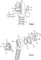
- Figure 1 shows the head 2 of a bone screw 4 as it might project from a bone (not shown) after installation during surgery.
- a housing 6 comprising a base 8 and a drum 10.
- the base 8 will normally be formed with a frusto conical recess which received the head 2 of the screw 4. This initially allows rotation of the base on the head, but once this is set in a desired orientation, it is locked by installation of a circlip 12.
- the drum 10 is formed with two threaded recesses (only one is shown) facing in opposite directions.
- a locking ring 14 holds a plate assembly 16 in the recess by virtue of an annular projection 18 from the base of each plate 16 engaging an annular shoulder 20 within the respective locking ring.
- a split ring 22 (only one is shown) holds the annular projection 18 and shoulder 20 in engagement during assembly of the device as a whole, and until the locking ring is tightened.
- the locking rings 14 are axially aligned around two cylindrical projections that also extend through the boss sections 26 of the plates 16 and define lateral axes along which the plates 16 can move.
- the distal end surface of the wall of each projection 14 has a concave spherical surface for reasons which are described below.
- Each plate 16 carries a clamp unit 28 which has a circular base received in a circular recess in the plate. This provides for rotation of each clamp unit 28 about an axis perpendicular to the common lateral axis of the plates 16.
- the circular base of the clamp unit will be held in the plate recess 30 by means of a resilient circlip (not shown).
- Each clamp unit has an outer jaw 32 and an inner jaw 34.
- the clamp unit itself is an integral body, and the movement of the jaws towards and away from each other is as a consequence of the resilient flexure of the material of the clamp and particularly of the inner jaw 34.
- each inner jaw is formed as a section extending from the outer jaw, and its mass and dimensions are generally less than those of the outer jaw to facilitate such relative movement.
- the outer face of each inner jaw has a convex spherical shape and is in juxtaposition with the distal end of the respective projection 24. The respective spherical surfaces match, such that there is uniform contact between them when they engage.
- each locking ring 14 When the device is assembled, each locking ring 14 may be rotated in its respective drum recess, the threads causing the ring to drive the respective plate inwards by virtue of engagement between the annular projection 18 on each plate, and the shoulder 20 on each locking ring.
- This movement causes the end face of the projections 24 to engage the convex face of the movable jaw 34 serving simultaneously to close the clamp unit 28, and lock it against rotation about either the lateral axis of the plate, or the perpendicular axis of the clamp unit.
- the engaging faces of the projection 24 and the movable jaw 34 may be knurled or otherwise roughened or treated to enhance the locking effect. Additional locking may be established by friction between the inner end face of each locking ring 14 and the base of the respective drum recess, by means of a resilient washer therebetween.
- the flexibility of the inner jaw 34 in each clamp unit 28 facilitates the initial insertion of fixation rods and once a rod is installed the device may be locked as described above, in a relatively swift and often single movement.
- a key can be provided for engaging openings 36 in each locking ring 14 to enable such locking to be quickly and effectively accomplished.
- Figure 3 shows how two fixation rods can be installed to extend between two devices of the kind illustrated in Figures 1 and 2 , and it will be noted that the drums 10 of the respective devices are not aligned in a common plane. This illustrates how the respective devices can be manoeuvred to ensure that the various locking mechanisms can be secured.
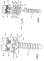
- Figure 4 illustrates an embodiment of the invention. Specifically, it shows how two fixation rods 40 and 42 can be mounted in alignment in two fixation devices of the kind described above, and interconnected by a sleeve 44.
- the rod 40 is fixed in the sleeve 44 by a clamping screw (now shown) in the bell 46.
- the rod 42 is slidably received in the other end of the sleeve 44.
- This construction enables the respective fixation devices to be installed in adjacent vertebra for example, but in a manner which allows the vertebra to grow apart without restriction by the fixation system.
- the rod 42 As damage is likely to be caused if the rod 42 were to exit the sleeve 44, its outward movement is restricted by an inwardly directed screw or spigot mounted in bell 48 that extends into a groove or similar (not shown) in the rod 42 which terminates before its end within the sleeve 44.
- the diameter of the fixation rods used in devices and systems of the invention will normally be around 4mm.
- the depth to which the rod ends are inserted and retained in the cylinders will normally be controlled to be at least equal to the rod diameter.
- Figure 4 shows rods extending on both sides of drums 10 mounted on screws 4 inserted or to be inserted in adjacent bone parts. It will though, be appreciated that there may well be circumstances in which only a single rod is required to be mounted on each screw 4. In those circumstances of course, it is not necessary to use a fixation device of the kind illustrated in Figures 1 to 3 .
- a single rod mounting device for example of the kind illustrated in Figure 1 of International Publication No: WO 02/03868 , or similar, may be used. Generally though, it is preferred to use aligned rods in parallel, for the reasons set out below.
- FIG. 5 shows an alternative sleeve and rod assembly.
- each sleeve is integral with one fixation rod section 52 to be clamped in a fixation device, for example of the kind illustrated in Figures 1 and 2 .
- the other end of each sleeve 50 receives a curved section 54 of the other fixation rod, which merges with a straight section 56 for clamping in a fixation device installed in an adjacent bone part such as another vertebra.
- the curved section 54 is formed with a groove 56 on its surface aligned with its axis.
- a screw 58 driven through the wall of the sleeve 50 extends into the groove 56.
- the groove stops short of the end of the rod within the sleeve to prevent it from withdrawing entirely from the sleeve.
- the engagement of the screw and groove also of course inhibits rotation of the rod relative to the sleeve.
- the interior of the sleeve which receives the rod section 54 is curved in the same sense.
- the curves are matched, and as a consequence the aligned rod sections define what is effectively a curved plane in which the adjacent bone parts are constrained.
- Figure 6 illustrates a similar arrangement to that of Figure 5 , but here the two sleeves are coupled together to provide greater stability as the rod sections 54 are withdrawn from the sleeves 50.
- the coupling unit 60 preserves the spacing between the sleeves, and any relative rotation. Where relatively large amount of movement must be accommodated between coupled bone parts, this additional control can be very valuable.
- FIG. 7 illustrates how fixation systems can be used after spinal surgery to control the alignment of adjacent vertebra while permitting them to grow apart.
- the vertebra are illustrated as rectanguloid blocks and as can be seen, each fixation system constrains the respective interconnected vertebra to move out of alignment as they grow apart. This serves to move adjacent vertebra, between which no fixation system is installed, to move out of alignment in the opposite sense, but in practice as a spine grows and develops the result will be that the vertebra grow in substantial alignment. It will be appreciated of course, that the degree of curvature in the rods and sleeves has to be selected with great care in order to achieve the desired result.
- Figure 8 illustrates a device which operates in a manner similar to that shown in Figure 1 , in that a rod is held in each of two clamps on the screw, each clamp being allowed to pivot until the orientation of the rod and clamp are secured.
- a housing 66 is mounted on a head 64 of a bone screw 62.
- the housing is secured on the head 64 by means of a locking pin 68.
- the housing itself comprises a bracket 70 on which are formed pairs of spaced part-cylindrical surfaces 72. These surface pairs define opposite sides of grooves extending beneath shoulders 74 which extend under the respective surfaces 72.
- Plates 76 are formed with part-cylindrical lower surfaces which complement and rest on the surfaces 72. Each plate can therefore pivot about a lateral axis defined by the common axis of the respective cylindrical surfaces. Of course, it is not essential that both plates pivot about the same axis, but in practice this will almost always be the case.
- Each clamp has a boss 80 which extends through an opening in its respective plate 76 and into the groove defined under and between the surfaces 72. There it is attached to a locking element 82 which extends laterally under the shoulders 74. Interposed between its locking element 82 and the respective shoulders 74 is a friction pad 84 to assist the locking process.
- Each clamp has two jaws 86 defining a groove for receiving a fixation rod (not shown).
- a clamping element 88 in the form of a screw with an Allen Key socket engages a complementary screw thread defined on the internal faces of the jaws 86.
- the holes in the plates 76 through which the bosses 80 extend have a chamfered perimeter. This enables the groove defined between the jaws 86 of each clamp to extend below the surface of the plate when the device is assembled.
- the clamping element 88 driven downwards to engage it, the rod itself is forced not against the base of the groove, but against the upper surface of a plate 76.
- the clamping element is tightened, the rod is locked in the groove; the clamp 86 is locked in the plate 76; and the plate 76 is locked against the surfaces 72 of the bracket 70 as the locking element 82 is drawn against the friction pad 84 and the shoulders 74.
- a single locking action secures a fixation rod against axial movement in the groove, and pivotal movement in any direction.
- Figure 10 illustrates a bone fixation device
- two separately lockable clamps are defined as part of a housing 90 mounted on the head of a bone screw 92, secured by means of a locking pin 94.
- the clamps are defined side-by-side in a unitary body 96.
- Each clamp has a locking element 98 similar to element 88 in Figure 8 , in the form of a screw engaging a complementary screw thread defined on the juxtaposed sides of a groove for receiving a fixation rod 100.
- the fixation rod passes through a split ball element 102 having an external spherical surface which rests in an internal spherical surface at a central section of the groove over which the locking element 98 is disposed. When the locking element is driven into the groove, it compresses the ball element to contract the bore therein through which the fixation rod extends, locking the rod in the ball element and the ball element in the groove.
- each groove end section preferably has a frusto-conical surface extending around more than 180°, for reasons that will become apparent.
- fixation rod 100 is locked in orientation, but can still move axially within the sleeve. The reason for this is explained below.
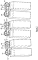
- Figure 11 illustrates how fixation devices can be used in spinal surgery.
- Three devices 106 are shown, mounted on alternate vertebra with a pair of fixation rods 108.
- Each rod 108 is secured by a clamp in each of the three devices 106.
- the devices and rods secure the alignment of the vertebra to which the devices are attached, and thereby the vertebra in between.
- the primary purpose of a fixation system of the kind illustrated in Figure 11 is to reinforce the spine and prevent undue curvature.
- Figure 12 illustrates a fixation system that serves an additional purpose.
- three devices are once again installed on alternate vertebra, but device 110 installed on the central vertebra clamps not fixation rods 108, but sleeves 112.
- Rods 114 are not continuous between the devices 106, but are discontinuous. This enables the spine to grow; ie, the vertebra on which the devices 106 are mounted can move away from each other during normal growth, while the rods and sleeves preserve the orientation and alignment of the vertebra to which the devices 106 and 110 are attached, and the intervening vertebra therebetween.
- fixation devices shown in Figures 11 and 12 could be any of the devices described above, as each provides the flexibility needed to accommodate rods and sleeves at the required orientation. It will be appreciated therefore, that while the mounting of a sleeve in a fixation device is only described with reference to the device of Figure 10 , the devices of Figures 1 and 8 can be readily adapted to perform the same function.
- Devices of the present invention provide a very convenient means by which an individual vertebra on which a device has been installed, can be manipulated with minimal direct contact between the surgeon's hands and the spine under surgery.
- the drum 10 of the housing 6 can be grasped either directly by the surgeon or remotely by a gripping device.
- one of the clamping elements (88,98) can be removed and a manipulator probe having a suitably threaded end installed in one of the clamps.
- a manipulator tool 116 having two pivotal arms 118 can lock onto the housing 90 by means of conical elements 120 at the distal ends of the arms engaging the frusto-conical surfaces of the end sections of one of the grooves.
- This technique has the advantage that the distal ends of the arms can be swiftly engaged or disengaged, and the length of the tool can enable manipulation to be conducted from a distance with a maximum amount of the vertebra being manipulated and adjacent vertebra, being in view.
- Devices and systems of the invention will normally be formed in titanium or, stainless steel or some other material which can be safely used in surgical applications.
- the use of resilient synthetic materials is best avoided, and for this reason the components must be manufactured with considerable precision.
Description
- This invention relates to fixation systems for bones after surgery, and has particular application to the setting or controlling of bone parts. It is applicable to the fixation of bone sections after fracture, and also to the relative orientation of bone parts such as vertebra between which some movement must be permitted after spinal surgery.
- Fixation devices for bone parts are known, and in this respect reference is directed to International Patent Publication No:
WO 02/03868 - That specification discloses a device in which one or two bone fixation rods are mounted on a bone screw to couple that screw to a similar screw in an adjacent bone part. The fixation rods are gripped relative to a support body mounted on bone screw between jaws which close in response to pressure generated by engagement against the wall of the support body. The present invention is directed at a similar device and related fixation systems, but which offer greater flexibility and versatility.
-
WO 2007/061960 A2 describes a fixation system according to the preamble of claim 1. According to the invention of our co-pending International Application entitled "Bone Fixation Device" claiming priority from British Patent Application No:0820251.7 - In preferred embodiments of the above invention, each clamp has an outer jaw and a movable inner jaw on a support rotatably mounted on the respective plate. The clamp locking mechanism comprises an element within the housing for engaging the inner jaw, to move it towards the outer jaw and thereby secure a fixation rod therebetween. This engagement can also lock one or both jaws against rotation about one or both of its lateral and perpendicular axes. The engaging surfaces may be textured or otherwise treated to achieve this locking effect. They would in any event, normally be matchingly spherical to maximise the surface engagement. The element itself may be fixed within the housing, with the respective plates being movable parallel to their lateral axes. Such movement inwards urges the inner jaw against the element. This inward movement may be effected by a locking ring with an external screw thread received in a complementary internal screw thread in the housing. The locking ring can overlay an inner shoulder on the respective plate against which it engages to urge the plate inwards. Rotation of the locking ring can in this way, by urging the inner jaw of the clamp against the housing element, simultaneously lock a rod in the clamp and the clamp against rotation about both of the lateral and perpendicular axes.
- In one simple form, the inner jaw of each clamp is mounted simply for pivotal movement relative to the outer jaw. Further, in order to minimise the number of moving parts, the inner and outer jaw are preferably integral parts of the same unit, and the pivotal movement is allowed by the deformation of the material used.
- Fixation devices of the kind referred to above are useful in many aspects of surgery, and are very effective when bone parts must be fixed relative to one another. A pair of fixation rods can extend between adjacent devices, to provide a very stable locking mechanism. At the same time, it will be appreciated that prior to the clamps and plates being locked, the loosely assembled structure of screws, fixation rods and bone parts can be manoeuvred into precise position. Once that position has been found, a single movement of each locking ring in the preferred embodiment can set the assembly.
- Fixation devices also have application in surgery where bone parts must be located relative to one another, but in a manner which allows for controlled relative movement. This is particular important after spinal surgery on a young patient who is still growing. For example, in a child treated for scoliosis a surgeon will want to set adjacent vertebra in such a manner that permits them to grow apart, but in a predetermined direction. In other words, the relative movement of the vertebra should be restricted to one which counteracts the deformity. This can be achieved in a fixation system according to the present invention in which fixation rods held in mounts on each of adjacent vertebra are coupled in a sleeve which allows the mounts (and therefore the vertebra) to separate, but only in a direction determined by the fixation rods and the respective sleeve or sleeves. The sleeve can receive juxtaposed rod ends between mounts, or can itself be secured in a mount. Generally, the end of one rod will be fixed in an end of the sleeve with the juxtaposed end of the other rod slidably received in the other end of the sleeve. The extent of movement of the other rod will normally be restricted to retain at least a minimum end length of each rod in the sleeve, and this can be accomplished by the end of the movable rod being formed with a longitudinal groove extending axially on its surface, but terminating short of the rod end. A spigot in the sleeve is received in the groove. The spigot is typically the end of a screw installed from the exterior of the sleeve, and therefore withdrawable to allow for initial insertion of the rod in the sleeve.
- A single rod and sleeve combination extending between mounts in adjacent vertebra provides some control over their relative movement, but it is preferred to use two such combinations side by side. The respective rods can be fixed in separate mounts on the vertebra, or on opposite sides of a housing on the exposed head of a bone screw, using a device of the kind described above. The use of two rods side by side does of course provide a much more stable and controlled link between the adjacent bone parts.
- If the permitted movement of adjacent bone parts using a fixation system according to the invention is to be linear, then the fixation rod and sleeve combination or preferably combinations will be straight. However, and particularly in surgery to combat scoliosis, the permitted movement may need to be along a curved path. This can be accomplished by selecting a rod or rods with appropriate curvature, and matching that curvature with a correspondingly curved sleeve, as necessary. Different circumstances will of course require different kinds and degrees of curvature, and different geometric figurations can be achieved by selecting appropriate rods and sleeves, and the respective orientations of the rods when they are fixed in the mounts in the respective bone parts.
- The fixation rods themselves will normally be of circular cross-section, but there may be situations in which a polygonal cross-section might have benefits. A polygonal cross-section of the rod and the sleeve interior will of course prevent rotation of one relative to the other. This can be additional to the use of the spigot and groove referred to above which does of course serve a similar purpose but can lock if a substantial twisting force is applied to a rod.
- As a further mechanism for stabilising relative movement of adjacent bone parts in a fixation system of the invention, the sleeves in which adjacent rods are received can be coupled together. This provides some additional resistance to adjacent vertebra twisting relative to one another.
- The invention will now be described by way of example and with reference to the accompanying illustrative drawings wherein:
-
Figure 1 is a perspective view of a bone fixation device; -
Figure 2 is a part exploded view of the device ofFigure 1 ; -
Figure 3 illustrates two devices with fixation rods extending therebetween; -
Figure 4 is a perspective view illustrating an embodiment of the invention; -
Figure 5 illustrates a variation on the embodiment ofFigure 4 ; -
Figure 6 illustrates a further variation; and -
Figure 7 illustrates schematically how the system ofFigure 6 can be applied in the treatment of spinal deformations. -
Figure 8 is a perspective view of a bone fixation device; -
Figure 9 is an exploded view of the device ofFigure 8 ; -
Figure 10 is a perspective view of a bone fixation device; -
Figure 11 illustrates schematically how devices of the kind shown inFigure 10 can be applied in the treatment of spinal deformations; -
Figure 12 shows a view similar to that ofFigure 11 in which spinal growth is accommodated; and -
Figure 13 illustrates how a tool can be coupled to a device of the kind shown inFigure 10 after installation on a vertebra to manipulate a vertebra during the course of an operation. -
Figure 1 shows thehead 2 of abone screw 4 as it might project from a bone (not shown) after installation during surgery. On the head is mounted ahousing 6 comprising abase 8 and adrum 10. Thebase 8 will normally be formed with a frusto conical recess which received thehead 2 of thescrew 4. This initially allows rotation of the base on the head, but once this is set in a desired orientation, it is locked by installation of acirclip 12. - As shown in
Figure 2 , thedrum 10 is formed with two threaded recesses (only one is shown) facing in opposite directions. When assembled, a lockingring 14 holds aplate assembly 16 in the recess by virtue of anannular projection 18 from the base of eachplate 16 engaging anannular shoulder 20 within the respective locking ring. A split ring 22 (only one is shown) holds theannular projection 18 andshoulder 20 in engagement during assembly of the device as a whole, and until the locking ring is tightened. - The locking rings 14 are axially aligned around two cylindrical projections that also extend through the
boss sections 26 of theplates 16 and define lateral axes along which theplates 16 can move. The distal end surface of the wall of eachprojection 14 has a concave spherical surface for reasons which are described below. - Each
plate 16 carries aclamp unit 28 which has a circular base received in a circular recess in the plate. This provides for rotation of eachclamp unit 28 about an axis perpendicular to the common lateral axis of theplates 16. The circular base of the clamp unit will be held in theplate recess 30 by means of a resilient circlip (not shown). - Each clamp unit has an
outer jaw 32 and aninner jaw 34. The clamp unit itself is an integral body, and the movement of the jaws towards and away from each other is as a consequence of the resilient flexure of the material of the clamp and particularly of theinner jaw 34. As can be seen, each inner jaw is formed as a section extending from the outer jaw, and its mass and dimensions are generally less than those of the outer jaw to facilitate such relative movement. The outer face of each inner jaw has a convex spherical shape and is in juxtaposition with the distal end of therespective projection 24. The respective spherical surfaces match, such that there is uniform contact between them when they engage. - When the device is assembled, each locking
ring 14 may be rotated in its respective drum recess, the threads causing the ring to drive the respective plate inwards by virtue of engagement between theannular projection 18 on each plate, and theshoulder 20 on each locking ring. This movement causes the end face of theprojections 24 to engage the convex face of themovable jaw 34 serving simultaneously to close theclamp unit 28, and lock it against rotation about either the lateral axis of the plate, or the perpendicular axis of the clamp unit. The engaging faces of theprojection 24 and themovable jaw 34 may be knurled or otherwise roughened or treated to enhance the locking effect. Additional locking may be established by friction between the inner end face of each lockingring 14 and the base of the respective drum recess, by means of a resilient washer therebetween. - The flexibility of the
inner jaw 34 in eachclamp unit 28 facilitates the initial insertion of fixation rods and once a rod is installed the device may be locked as described above, in a relatively swift and often single movement. A key can be provided for engagingopenings 36 in each lockingring 14 to enable such locking to be quickly and effectively accomplished. -
Figure 3 shows how two fixation rods can be installed to extend between two devices of the kind illustrated inFigures 1 and 2 , and it will be noted that thedrums 10 of the respective devices are not aligned in a common plane. This illustrates how the respective devices can be manoeuvred to ensure that the various locking mechanisms can be secured. -
Figure 4 illustrates an embodiment of the invention. Specifically, it shows how twofixation rods sleeve 44. Therod 40 is fixed in thesleeve 44 by a clamping screw (now shown) in thebell 46. Therod 42 is slidably received in the other end of thesleeve 44. This construction enables the respective fixation devices to be installed in adjacent vertebra for example, but in a manner which allows the vertebra to grow apart without restriction by the fixation system. However, as damage is likely to be caused if therod 42 were to exit thesleeve 44, its outward movement is restricted by an inwardly directed screw or spigot mounted inbell 48 that extends into a groove or similar (not shown) in therod 42 which terminates before its end within thesleeve 44. The diameter of the fixation rods used in devices and systems of the invention will normally be around 4mm. The depth to which the rod ends are inserted and retained in the cylinders will normally be controlled to be at least equal to the rod diameter. -
Figure 4 shows rods extending on both sides ofdrums 10 mounted onscrews 4 inserted or to be inserted in adjacent bone parts. It will though, be appreciated that there may well be circumstances in which only a single rod is required to be mounted on eachscrew 4. In those circumstances of course, it is not necessary to use a fixation device of the kind illustrated inFigures 1 to 3 . A single rod mounting device, for example of the kind illustrated inFigure 1 of International Publication No:WO 02/03868 -
Figure 5 shows an alternative sleeve and rod assembly. In this embodiment, each sleeve is integral with onefixation rod section 52 to be clamped in a fixation device, for example of the kind illustrated inFigures 1 and 2 . The other end of eachsleeve 50 receives acurved section 54 of the other fixation rod, which merges with astraight section 56 for clamping in a fixation device installed in an adjacent bone part such as another vertebra. Thecurved section 54 is formed with agroove 56 on its surface aligned with its axis. Ascrew 58 driven through the wall of thesleeve 50 extends into thegroove 56. The groove stops short of the end of the rod within the sleeve to prevent it from withdrawing entirely from the sleeve. The engagement of the screw and groove also of course inhibits rotation of the rod relative to the sleeve. The interior of the sleeve which receives therod section 54 is curved in the same sense. Thus, as therod 54 is withdrawn from the sleeve as the attached bone parts (vertebra) separate, such separation is constrained to be along the line of the curve, as indicated. With two sleeves and respective rod sections, the curves are matched, and as a consequence the aligned rod sections define what is effectively a curved plane in which the adjacent bone parts are constrained. -
Figure 6 illustrates a similar arrangement to that ofFigure 5 , but here the two sleeves are coupled together to provide greater stability as therod sections 54 are withdrawn from thesleeves 50. Thecoupling unit 60 preserves the spacing between the sleeves, and any relative rotation. Where relatively large amount of movement must be accommodated between coupled bone parts, this additional control can be very valuable. -
Figure 7 illustrates how fixation systems can be used after spinal surgery to control the alignment of adjacent vertebra while permitting them to grow apart. The vertebra are illustrated as rectanguloid blocks and as can be seen, each fixation system constrains the respective interconnected vertebra to move out of alignment as they grow apart. This serves to move adjacent vertebra, between which no fixation system is installed, to move out of alignment in the opposite sense, but in practice as a spine grows and develops the result will be that the vertebra grow in substantial alignment. It will be appreciated of course, that the degree of curvature in the rods and sleeves has to be selected with great care in order to achieve the desired result. -
Figure 8 illustrates a device which operates in a manner similar to that shown inFigure 1 , in that a rod is held in each of two clamps on the screw, each clamp being allowed to pivot until the orientation of the rod and clamp are secured. In a manner similar to the device ofFigure 1 , ahousing 66 is mounted on ahead 64 of abone screw 62. In the device ofFigure 8 , the housing is secured on thehead 64 by means of a lockingpin 68. The housing itself comprises abracket 70 on which are formed pairs of spaced part-cylindrical surfaces 72. These surface pairs define opposite sides of grooves extending beneathshoulders 74 which extend under the respective surfaces 72. -
Plates 76 are formed with part-cylindrical lower surfaces which complement and rest on thesurfaces 72. Each plate can therefore pivot about a lateral axis defined by the common axis of the respective cylindrical surfaces. Of course, it is not essential that both plates pivot about the same axis, but in practice this will almost always be the case. - Supported on the
respective plates 76 areclamps 78. Each clamp has aboss 80 which extends through an opening in itsrespective plate 76 and into the groove defined under and between thesurfaces 72. There it is attached to a lockingelement 82 which extends laterally under theshoulders 74. Interposed between its lockingelement 82 and therespective shoulders 74 is afriction pad 84 to assist the locking process. - Each clamp has two
jaws 86 defining a groove for receiving a fixation rod (not shown). A clampingelement 88 in the form of a screw with an Allen Key socket engages a complementary screw thread defined on the internal faces of thejaws 86. - As can be seen in
Figure 9 , the holes in theplates 76 through which thebosses 80 extend have a chamfered perimeter. This enables the groove defined between thejaws 86 of each clamp to extend below the surface of the plate when the device is assembled. As a consequence, when a fixation rod is fitted in a groove, and the clampingelement 88 driven downwards to engage it, the rod itself is forced not against the base of the groove, but against the upper surface of aplate 76. Thus, when the clamping element is tightened, the rod is locked in the groove; theclamp 86 is locked in theplate 76; and theplate 76 is locked against thesurfaces 72 of thebracket 70 as the lockingelement 82 is drawn against thefriction pad 84 and theshoulders 74. As with the device ofFigure 1 then, a single locking action secures a fixation rod against axial movement in the groove, and pivotal movement in any direction. -
Figure 10 illustrates a bone fixation device. - As with the devices of
Figures 1 and8 , two separately lockable clamps are defined as part of ahousing 90 mounted on the head of abone screw 92, secured by means of a lockingpin 94. However, in the device ofFigure 10 the clamps are defined side-by-side in aunitary body 96. Each clamp has a lockingelement 98 similar toelement 88 inFigure 8 , in the form of a screw engaging a complementary screw thread defined on the juxtaposed sides of a groove for receiving afixation rod 100. However, in the device ofFigure 10 the fixation rod passes through asplit ball element 102 having an external spherical surface which rests in an internal spherical surface at a central section of the groove over which thelocking element 98 is disposed. When the locking element is driven into the groove, it compresses the ball element to contract the bore therein through which the fixation rod extends, locking the rod in the ball element and the ball element in the groove. - While the clamping
element 98 is disengaged or only loosely engaged with theball element 102, the ball element can pivot in the groove within the central spherical surface. The end sections of the groove diverge from the central section to allow arod 100 fitted in theball element 102 limited pivotal movement also about the centre of theball element 102. The base of each groove end section preferably has a frusto-conical surface extending around more than 180°, for reasons that will become apparent. - The above description of the installation of a fixation rod is described above with reference to the clamp shown on the righthand side in the device of
Figure 10 . The clamp on the lefthand side of the device shown inFigure 10 is essentially similar, but the bore through theball element 102 is larger. This enables it to receive asleeve 104, which has limited pivotal movement while the clamping element is disengaged, but can be locked in a similar way when the element is engaged. However, thefixation rod 100 is locked in orientation, but can still move axially within the sleeve. The reason for this is explained below. -
Figure 11 illustrates how fixation devices can be used in spinal surgery. Threedevices 106 are shown, mounted on alternate vertebra with a pair offixation rods 108. Eachrod 108 is secured by a clamp in each of the threedevices 106. As shown therefore, the devices and rods secure the alignment of the vertebra to which the devices are attached, and thereby the vertebra in between. The primary purpose of a fixation system of the kind illustrated inFigure 11 is to reinforce the spine and prevent undue curvature. -
Figure 12 illustrates a fixation system that serves an additional purpose. In the system ofFigure 12 , three devices are once again installed on alternate vertebra, but device 110 installed on the central vertebra clamps notfixation rods 108, butsleeves 112.Rods 114 are not continuous between thedevices 106, but are discontinuous. This enables the spine to grow; ie, the vertebra on which thedevices 106 are mounted can move away from each other during normal growth, while the rods and sleeves preserve the orientation and alignment of the vertebra to which thedevices 106 and 110 are attached, and the intervening vertebra therebetween. - It will be appreciated that the fixation devices shown in
Figures 11 and 12 could be any of the devices described above, as each provides the flexibility needed to accommodate rods and sleeves at the required orientation. It will be appreciated therefore, that while the mounting of a sleeve in a fixation device is only described with reference to the device ofFigure 10 , the devices ofFigures 1 and8 can be readily adapted to perform the same function. - In the conduct of delicate spinal surgery, it is often necessary to manipulate individual vertebra in the spine before fitting a fixation system of the kind described above. Such manipulation has to be conducted with great care and accuracy. This is not always possible when using a surgeon's hand. Devices of the present invention provide a very convenient means by which an individual vertebra on which a device has been installed, can be manipulated with minimal direct contact between the surgeon's hands and the spine under surgery. In the device of
Figure 1 , thedrum 10 of thehousing 6 can be grasped either directly by the surgeon or remotely by a gripping device. In the devices ofFigures 8 and10 one of the clamping elements (88,98) can be removed and a manipulator probe having a suitably threaded end installed in one of the clamps. The device ofFigure 10 provides a particularly convenient alternative to these techniques. As shown inFigure 13 , amanipulator tool 116 having twopivotal arms 118 can lock onto thehousing 90 by means ofconical elements 120 at the distal ends of the arms engaging the frusto-conical surfaces of the end sections of one of the grooves. This technique has the advantage that the distal ends of the arms can be swiftly engaged or disengaged, and the length of the tool can enable manipulation to be conducted from a distance with a maximum amount of the vertebra being manipulated and adjacent vertebra, being in view. - Devices and systems of the invention will normally be formed in titanium or, stainless steel or some other material which can be safely used in surgical applications. The use of resilient synthetic materials is best avoided, and for this reason the components must be manufactured with considerable precision.
Claims (7)
- A fixation system for controlling the alignment of adjacent vertebra after spinal surgery, which system comprises aligned fixation rods (40,42,52,56); a mount (4) for installation on each of said vertebra and for holding a fixation rod; and a sleeve (44,50) for receiving the juxtaposed ends of the rods in alignment between the mounts (4), wherein: at least one (42) of the rods is movable in the sleeve (44) relative to the other (40) to allow controlled movement of adjacent vertebra, and the rods (40,42,52,56) and sleeve (44,50) have matching curvatures selected to achieve a predetermined geometric figuration as they move relative to one another,
CHARACTERISED IN THAT:the at least one (42) of the rods comprises a longitudinal groove extending axially on the surface of the at least one (42) of the rods, the groove terminating short of the end of the at least one (42) of the rods; andthe sleeve (44,50) is configured to receive an inwardly directed screw (58) through the wall of the sleeve (44,50) such that the screw (58) extends into the longitudinal groove (55) to restrict said movement of the at least one (42) of the rods to retain a minimum end length thereof in the sleeve and to inhibit rotation of the at least one (42) of the rods relative to the sleeve (44,50). - A fixation system for controlling the alignment of adjacent vertebra after spinal surgery, which system comprises aligned fixation rods (40,42); a mount (4) for installation on each of said vertebra and for holding a fixation rod; and a sleeve (44) for receiving the juxtaposed ends of the rods in alignment, the sleeve being secured in said mount (4), wherein:at least one (42) of the rods is movable in the sleeve (44) relative to the other (40) to allow controlled movement of adjacent vertebra, and the rods (40,42,52,56) and sleeve (44,50) have matching curvatures selected to achieve a predetermined geometric figuration as they move relative to one another,CHARACTERISED IN THAT:the at least one (42) of the rods comprises a longitudinal groove (55) extending axially on the surface of the at least one (42) of the rods, the groove terminating short of the end of the at least one (42) of the rods;the sleeve (44,50) is configured to receive an inwardly directed screw (58) through the wall of the sleeve (44,50) such that the screw (58) extends into the longitudinal groove (55) to restrict said movement of the at least one (42) of the rods to retain a minimum end length thereof in the sleeve and to inhibit rotation of the at least one (42) of the rods relative to the sleeve (44,50).
- A fixation system according to any preceding Claim wherein the movable rod (42,56) and the section of the sleeve (44,50) in which it is received have complementary non-circular cross-sections preventing rotation of the rod in the sleeve.
- A fixation system according to any preceding Claim including a pair of said mounts (4) for holding fixation rods on each said vertebra; and two said sleeves (50) for receiving juxtaposed ends of the respective rods (40,42,52,56), the rods and sleeves defining a plane of permitted movement.
- A fixation system according to Claim 4 wherein the two sleeves (50) are coupled together (60).
- A fixation system according to Claim 4 or Claim 5 wherein each pair of mounts (4) is part of the same device secured to a said vertebra.
- A fixation system according to any preceding Claim wherein at least one rod (40,42,52,56) is fixed relative to its respective sleeve (44,50) in an integral unit.
Applications Claiming Priority (2)
| Application Number | Priority Date | Filing Date | Title |
|---|---|---|---|
| GB0820252.5A GB2465156B (en) | 2008-11-05 | 2008-11-05 | Bone fixation system |
| PCT/GB2009/002616 WO2010052465A1 (en) | 2008-11-05 | 2009-11-05 | Bone fixation system |
Publications (2)
| Publication Number | Publication Date |
|---|---|
| EP2344057A1 EP2344057A1 (en) | 2011-07-20 |
| EP2344057B1 true EP2344057B1 (en) | 2017-05-10 |
Family
ID=40138356
Family Applications (1)
| Application Number | Title | Priority Date | Filing Date |
|---|---|---|---|
| EP09753177.6A Not-in-force EP2344057B1 (en) | 2008-11-05 | 2009-11-05 | Bone fixation system |
Country Status (5)
| Country | Link |
|---|---|
| US (2) | US20110282391A1 (en) |
| EP (1) | EP2344057B1 (en) |
| JP (1) | JP2012507317A (en) |
| GB (1) | GB2465156B (en) |
| WO (1) | WO2010052465A1 (en) |
Families Citing this family (19)
| Publication number | Priority date | Publication date | Assignee | Title |
|---|---|---|---|---|
| US8100946B2 (en) | 2005-11-21 | 2012-01-24 | Synthes Usa, Llc | Polyaxial bone anchors with increased angulation |
| US9439681B2 (en) | 2007-07-20 | 2016-09-13 | DePuy Synthes Products, Inc. | Polyaxial bone fixation element |
| US9345517B2 (en) * | 2008-02-02 | 2016-05-24 | Globus Medical, Inc. | Pedicle screw having a removable rod coupling |
| WO2009097623A2 (en) * | 2008-02-02 | 2009-08-06 | Texas Scottish Rite Hospital For Children | Pedicle screw |
| US20100049252A1 (en) * | 2008-08-21 | 2010-02-25 | Southern Spine, Llc | Transverse Connector Device for Extending an Existing Spinal Fixation System |
| EP2337512B1 (en) | 2008-09-12 | 2012-03-14 | Synthes GmbH | Spinal stabilizing and guiding fixation system |
| DE09793113T8 (en) | 2008-09-29 | 2013-04-25 | Synthes Gmbh | POLYAXIAL BOTTOM CHARGE SCREW AND BAR ASSEMBLY |
| CA2742399A1 (en) | 2008-11-03 | 2010-06-03 | Dustin M. Harvey | Uni-planar bone fixation assembly |
| CN102368967B (en) | 2009-04-15 | 2016-03-02 | 斯恩蒂斯有限公司 | For the revision connector of spinal structure |
| EP2442738B1 (en) | 2009-06-17 | 2014-04-30 | Synthes GmbH | Revision connector for spinal constructs |
| GB0915382D0 (en) | 2009-09-03 | 2009-10-07 | Dalmatic As | Expansion devices |
| US20110098748A1 (en) * | 2009-10-26 | 2011-04-28 | Warsaw Orthopedic, Inc. | Adjustable vertebral rod system and methods of use |
| KR20120123298A (en) | 2009-12-01 | 2012-11-08 | 신세스 게엠바하 | Non-fusion scoliosis expandable spinal rod |
| AU2011331999B2 (en) | 2010-11-22 | 2016-07-21 | Synthes Gmbh | Non-fusion scoliosis expandable spinal rod |
| EP2460482A1 (en) * | 2010-12-03 | 2012-06-06 | Zimmer Spine | Rod holding device |
| US20120203281A1 (en) * | 2011-02-05 | 2012-08-09 | Alphatec Spine, Inc | Semi-rigid screw assembly |
| EP2662037B1 (en) * | 2012-05-09 | 2023-01-11 | CoLigne AG | Iliac connector, connector head and spinal fixation system |
| US10265103B2 (en) * | 2016-08-18 | 2019-04-23 | Premia Spine Ltd. | Spinal prosthesis with adjustable support element |
| US11737793B2 (en) | 2017-10-20 | 2023-08-29 | Mayo Foundation For Medical Education And Research | Facet joint replacement devices |
Citations (2)
| Publication number | Priority date | Publication date | Assignee | Title |
|---|---|---|---|---|
| US20060036240A1 (en) * | 2004-08-09 | 2006-02-16 | Innovative Spinal Technologies | System and method for dynamic skeletal stabilization |
| US20060265074A1 (en) * | 2004-10-21 | 2006-11-23 | Manoj Krishna | Posterior spinal arthroplasty-development of a new posteriorly inserted artificial disc, a new anteriorly inserted artifical disc and an artificial facet joint |
Family Cites Families (44)
| Publication number | Priority date | Publication date | Assignee | Title |
|---|---|---|---|---|
| DE3306657C2 (en) * | 1983-02-25 | 1986-12-11 | Fa. Heinrich C. Ulrich, 7900 Ulm | Spine correction implant with a distraction rod |
| US4620533A (en) | 1985-09-16 | 1986-11-04 | Pfizer Hospital Products Group Inc. | External bone fixation apparatus |
| US4771767A (en) | 1986-02-03 | 1988-09-20 | Acromed Corporation | Apparatus and method for maintaining vertebrae in a desired relationship |
| FR2720261B1 (en) | 1994-05-27 | 1996-09-13 | Pascal Aufaure | Implant for osteosynthesis device. |
| FR2724553B1 (en) | 1994-09-15 | 1996-12-20 | Tornier Sa | EXTERNAL OR INTERNAL FIXER FOR THE REPAIR OF FRACTURES OR ARTHROPLASTIES OF THE SKELETON |
| US5620443A (en) * | 1995-01-25 | 1997-04-15 | Danek Medical, Inc. | Anterior screw-rod connector |
| FR2731344B1 (en) | 1995-03-06 | 1997-08-22 | Dimso Sa | SPINAL INSTRUMENTATION ESPECIALLY FOR A ROD |
| JP3338944B2 (en) * | 1995-08-25 | 2002-10-28 | 有限会社田中医科器械製作所 | Spinal deformity correction device |
| JPH10171304A (en) | 1996-03-14 | 1998-06-26 | Matsushita Electric Ind Co Ltd | Color image forming device |
| JP3172703B2 (en) | 1997-12-18 | 2001-06-04 | 株式会社ロバート・リード商会 | Bone fixation device |
| US6565569B1 (en) | 1998-04-29 | 2003-05-20 | Stryker Spine | Backbone osteosynthesis system with clamping means, in particlular for anterior fixing |
| FR2794357B1 (en) * | 1999-06-01 | 2001-09-14 | Frederic Fortin | DISTRACTION DEVICE FOR BONES OF CHILDREN HAVING HANGING AND ADJUSTMENT MEANS FOR TRACKING GROWTH |
| US6524315B1 (en) | 2000-08-08 | 2003-02-25 | Depuy Acromed, Inc. | Orthopaedic rod/plate locking mechanism |
| US6565564B2 (en) | 2000-12-14 | 2003-05-20 | Synthes U.S.A. | Multi-pin clamp and rod attachment |
| US6802844B2 (en) | 2001-03-26 | 2004-10-12 | Nuvasive, Inc | Spinal alignment apparatus and methods |
| FR2827498B1 (en) * | 2001-07-18 | 2004-05-14 | Frederic Fortin | FLEXIBLE VERTEBRAL CONNECTION DEVICE CONSISTING OF PALLIANT ELEMENTS OF THE RACHIS |
| EP2238934B1 (en) | 2001-10-23 | 2011-12-21 | Biedermann Motech GmbH | Bone fixation device and screw for such |
| US20060079892A1 (en) | 2001-10-31 | 2006-04-13 | Suranjan Roychowdhury | Adjustable tandem connectors for corrective devices for the spinal column and other bones and joints |
| FR2832620B1 (en) | 2001-11-27 | 2004-01-23 | Eurosurgical | CONNECTOR FOR VERTEBRAL ANCHORAGE SYSTEM |
| US20040111088A1 (en) | 2002-12-06 | 2004-06-10 | Picetti George D. | Multi-rod bone attachment member |
| US7785351B2 (en) * | 2003-08-05 | 2010-08-31 | Flexuspine, Inc. | Artificial functional spinal implant unit system and method for use |
| US7819902B2 (en) | 2004-02-27 | 2010-10-26 | Custom Spine, Inc. | Medialised rod pedicle screw assembly |
| US7648520B2 (en) | 2004-04-16 | 2010-01-19 | Kyphon Sarl | Pedicle screw assembly |
| WO2006004468A1 (en) * | 2004-07-02 | 2006-01-12 | Volvo Technology Corporation | Internal combustion engine exhaust gas system |
| BRPI0419057A (en) * | 2004-09-22 | 2007-12-11 | Kyung-Woo Park | spinal fixation |
| US8162985B2 (en) * | 2004-10-20 | 2012-04-24 | The Board Of Trustees Of The Leland Stanford Junior University | Systems and methods for posterior dynamic stabilization of the spine |
| DE202005005444U1 (en) | 2005-04-01 | 2005-06-02 | Tantum Ag | Particularly stable bone fixing device, assembled of two central elements and two fixing rods holding devices |
| EP1933739B1 (en) | 2005-10-07 | 2013-09-18 | Alphatec Spine, Inc. | Adjustable occipital plate |
| GB0521582D0 (en) * | 2005-10-22 | 2005-11-30 | Depuy Int Ltd | An implant for supporting a spinal column |
| US7803174B2 (en) | 2005-11-04 | 2010-09-28 | Warsaw Orthopedic, Inc. | Dorsal adjusting multi-rod connector |
| AU2006318673A1 (en) * | 2005-11-18 | 2007-05-31 | Life Spine, Inc. | Dynamic spinal stabilization devices and systems |
| US7585299B2 (en) | 2006-02-17 | 2009-09-08 | Warsaw Orthopedic, Inc. | Dorsal adjusting spinal connector assembly |
| EP2308402A3 (en) * | 2006-05-15 | 2011-04-27 | Biomet Spain Orthopaedics S.L. | Surgical screw system |
| US8475499B2 (en) * | 2006-07-14 | 2013-07-02 | DePuy Synthes Products, LLC. | Rod to rod connectors and methods of adjusting the length of a spinal rod construct |
| US20080058805A1 (en) * | 2006-08-28 | 2008-03-06 | Microdexterity Systems, Inc. | Spinal fusion implant |
| US8029541B2 (en) * | 2006-10-19 | 2011-10-04 | Simpirica Spine, Inc. | Methods and systems for laterally stabilized constraint of spinous processes |
| FR2910267B1 (en) * | 2006-12-21 | 2009-01-23 | Ldr Medical Soc Par Actions Si | VERTEBRAL SUPPORT DEVICE |
| US8109975B2 (en) * | 2007-01-30 | 2012-02-07 | Warsaw Orthopedic, Inc. | Collar bore configuration for dynamic spinal stabilization assembly |
| ES2392351T3 (en) * | 2007-02-23 | 2012-12-07 | Biedermann Technologies Gmbh & Co. Kg | Device to stabilize vertebrae |
| US8337527B2 (en) | 2007-04-18 | 2012-12-25 | Ebi, Llc | Spinal connector |
| JP2011511676A (en) * | 2008-02-07 | 2011-04-14 | ケー2エム, インコーポレイテッド | Automatic expansion bone fixation device |
| US20090264931A1 (en) | 2008-04-18 | 2009-10-22 | Warsaw Orthopedic, Inc. | Implantable Article for Use with an Anchor and a Non-Metal Rod |
| US8197516B2 (en) * | 2008-07-01 | 2012-06-12 | The University Of Toledo | Lateral fixation assembly for spinal column |
| EP2174608B1 (en) * | 2008-10-08 | 2012-08-01 | Biedermann Technologies GmbH & Co. KG | Bone anchoring device and stabilization device for bone parts or vertebrae |
-
2008
- 2008-11-05 GB GB0820252.5A patent/GB2465156B/en not_active Expired - Fee Related
-
2009
- 2009-11-05 WO PCT/GB2009/002616 patent/WO2010052465A1/en active Application Filing
- 2009-11-05 EP EP09753177.6A patent/EP2344057B1/en not_active Not-in-force
- 2009-11-05 JP JP2011533825A patent/JP2012507317A/en active Pending
- 2009-11-05 US US13/127,773 patent/US20110282391A1/en not_active Abandoned
-
2014
- 2014-04-15 US US14/253,480 patent/US9439679B2/en active Active
Patent Citations (2)
| Publication number | Priority date | Publication date | Assignee | Title |
|---|---|---|---|---|
| US20060036240A1 (en) * | 2004-08-09 | 2006-02-16 | Innovative Spinal Technologies | System and method for dynamic skeletal stabilization |
| US20060265074A1 (en) * | 2004-10-21 | 2006-11-23 | Manoj Krishna | Posterior spinal arthroplasty-development of a new posteriorly inserted artificial disc, a new anteriorly inserted artifical disc and an artificial facet joint |
Also Published As
| Publication number | Publication date |
|---|---|
| WO2010052465A1 (en) | 2010-05-14 |
| GB2465156A8 (en) | 2012-10-03 |
| GB2465156B (en) | 2012-09-26 |
| US20140228888A1 (en) | 2014-08-14 |
| US20110282391A1 (en) | 2011-11-17 |
| US9439679B2 (en) | 2016-09-13 |
| GB0820252D0 (en) | 2008-12-10 |
| EP2344057A1 (en) | 2011-07-20 |
| JP2012507317A (en) | 2012-03-29 |
| GB2465156A (en) | 2010-05-12 |
Similar Documents
| Publication | Publication Date | Title |
|---|---|---|
| EP2344057B1 (en) | Bone fixation system | |
| EP2344056B1 (en) | Bone fixation device | |
| US6379356B1 (en) | Closure for open ended medical implant | |
| US6090113A (en) | Adjustable osteosynthesis system of the rachis | |
| US9532805B2 (en) | Single lock external fixation clamp arrangement and method | |
| US6258090B1 (en) | Closure for open ended medical implant and removal tool | |
| US10702315B2 (en) | Medical instrument for provisionally fastening a polyaxial pedicle screw | |
| CA2710738C (en) | External fixation component | |
| EP2768411B1 (en) | Derotation apparatus for treating spinal irregularities | |
| EP2465454B1 (en) | Fixation clamp with thumbwheel | |
| US20050228382A1 (en) | Screw and rod fixation assembly and device | |
| EP3295880B1 (en) | Spinal rod link reducer | |
| JP2012529969A (en) | Longitudinal connecting member with tensioning cord with sleeve | |
| EP0584179A1 (en) | A clamp for use in spinal surgery | |
| WO2007092876A2 (en) | Methods and instruments for spinal derotation | |
| MXPA04003800A (en) | An instrument system for pedicle screws. | |
| WO2015066044A1 (en) | External fixation system and methods of use | |
| EP2793719B1 (en) | Bone fixation device | |
| KR20180134861A (en) | Tools to dynamically stabilize and locate intervertebral implants |
Legal Events
| Date | Code | Title | Description |
|---|---|---|---|
| PUAI | Public reference made under article 153(3) epc to a published international application that has entered the european phase |
Free format text: ORIGINAL CODE: 0009012 |
|
| 17P | Request for examination filed |
Effective date: 20110427 |
|
| AK | Designated contracting states |
Kind code of ref document: A1 Designated state(s): AT BE BG CH CY CZ DE DK EE ES FI FR GB GR HR HU IE IS IT LI LT LU LV MC MK MT NL NO PL PT RO SE SI SK SM TR |
|
| AX | Request for extension of the european patent |
Extension state: AL BA RS |
|
| DAX | Request for extension of the european patent (deleted) | ||
| RIN1 | Information on inventor provided before grant (corrected) |
Inventor name: BUENGER, CODY, ERIC Inventor name: DALL, VAGN, ERIK |
|
| 17Q | First examination report despatched |
Effective date: 20150216 |
|
| GRAP | Despatch of communication of intention to grant a patent |
Free format text: ORIGINAL CODE: EPIDOSNIGR1 |
|
| INTG | Intention to grant announced |
Effective date: 20161018 |
|
| GRAJ | Information related to disapproval of communication of intention to grant by the applicant or resumption of examination proceedings by the epo deleted |
Free format text: ORIGINAL CODE: EPIDOSDIGR1 |
|
| GRAR | Information related to intention to grant a patent recorded |
Free format text: ORIGINAL CODE: EPIDOSNIGR71 |
|
| GRAS | Grant fee paid |
Free format text: ORIGINAL CODE: EPIDOSNIGR3 |
|
| INTC | Intention to grant announced (deleted) | ||
| GRAA | (expected) grant |
Free format text: ORIGINAL CODE: 0009210 |
|
| AK | Designated contracting states |
Kind code of ref document: B1 Designated state(s): AT BE BG CH CY CZ DE DK EE ES FI FR GB GR HR HU IE IS IT LI LT LU LV MC MK MT NL NO PL PT RO SE SI SK SM TR |
|
| INTG | Intention to grant announced |
Effective date: 20170404 |
|
| REG | Reference to a national code |
Ref country code: GB Ref legal event code: FG4D |
|
| REG | Reference to a national code |
Ref country code: AT Ref legal event code: REF Ref document number: 891483 Country of ref document: AT Kind code of ref document: T Effective date: 20170515 Ref country code: CH Ref legal event code: EP |
|
| REG | Reference to a national code |
Ref country code: IE Ref legal event code: FG4D |
|
| REG | Reference to a national code |
Ref country code: DE Ref legal event code: R096 Ref document number: 602009046006 Country of ref document: DE |
|
| REG | Reference to a national code |
Ref country code: CH Ref legal event code: NV Representative=s name: SERVOPATENT GMBH, CH |
|
| REG | Reference to a national code |
Ref country code: NL Ref legal event code: MP Effective date: 20170510 |
|
| REG | Reference to a national code |
Ref country code: LT Ref legal event code: MG4D |
|
| REG | Reference to a national code |
Ref country code: AT Ref legal event code: MK05 Ref document number: 891483 Country of ref document: AT Kind code of ref document: T Effective date: 20170510 |
|
| PG25 | Lapsed in a contracting state [announced via postgrant information from national office to epo] |
Ref country code: GR Free format text: LAPSE BECAUSE OF FAILURE TO SUBMIT A TRANSLATION OF THE DESCRIPTION OR TO PAY THE FEE WITHIN THE PRESCRIBED TIME-LIMIT Effective date: 20170811 Ref country code: NO Free format text: LAPSE BECAUSE OF FAILURE TO SUBMIT A TRANSLATION OF THE DESCRIPTION OR TO PAY THE FEE WITHIN THE PRESCRIBED TIME-LIMIT Effective date: 20170810 Ref country code: ES Free format text: LAPSE BECAUSE OF FAILURE TO SUBMIT A TRANSLATION OF THE DESCRIPTION OR TO PAY THE FEE WITHIN THE PRESCRIBED TIME-LIMIT Effective date: 20170510 Ref country code: HR Free format text: LAPSE BECAUSE OF FAILURE TO SUBMIT A TRANSLATION OF THE DESCRIPTION OR TO PAY THE FEE WITHIN THE PRESCRIBED TIME-LIMIT Effective date: 20170510 Ref country code: AT Free format text: LAPSE BECAUSE OF FAILURE TO SUBMIT A TRANSLATION OF THE DESCRIPTION OR TO PAY THE FEE WITHIN THE PRESCRIBED TIME-LIMIT Effective date: 20170510 Ref country code: FI Free format text: LAPSE BECAUSE OF FAILURE TO SUBMIT A TRANSLATION OF THE DESCRIPTION OR TO PAY THE FEE WITHIN THE PRESCRIBED TIME-LIMIT Effective date: 20170510 Ref country code: LT Free format text: LAPSE BECAUSE OF FAILURE TO SUBMIT A TRANSLATION OF THE DESCRIPTION OR TO PAY THE FEE WITHIN THE PRESCRIBED TIME-LIMIT Effective date: 20170510 |
|
| PG25 | Lapsed in a contracting state [announced via postgrant information from national office to epo] |
Ref country code: PL Free format text: LAPSE BECAUSE OF FAILURE TO SUBMIT A TRANSLATION OF THE DESCRIPTION OR TO PAY THE FEE WITHIN THE PRESCRIBED TIME-LIMIT Effective date: 20170510 Ref country code: LV Free format text: LAPSE BECAUSE OF FAILURE TO SUBMIT A TRANSLATION OF THE DESCRIPTION OR TO PAY THE FEE WITHIN THE PRESCRIBED TIME-LIMIT Effective date: 20170510 Ref country code: BG Free format text: LAPSE BECAUSE OF FAILURE TO SUBMIT A TRANSLATION OF THE DESCRIPTION OR TO PAY THE FEE WITHIN THE PRESCRIBED TIME-LIMIT Effective date: 20170810 Ref country code: SE Free format text: LAPSE BECAUSE OF FAILURE TO SUBMIT A TRANSLATION OF THE DESCRIPTION OR TO PAY THE FEE WITHIN THE PRESCRIBED TIME-LIMIT Effective date: 20170510 Ref country code: NL Free format text: LAPSE BECAUSE OF FAILURE TO SUBMIT A TRANSLATION OF THE DESCRIPTION OR TO PAY THE FEE WITHIN THE PRESCRIBED TIME-LIMIT Effective date: 20170510 Ref country code: IS Free format text: LAPSE BECAUSE OF FAILURE TO SUBMIT A TRANSLATION OF THE DESCRIPTION OR TO PAY THE FEE WITHIN THE PRESCRIBED TIME-LIMIT Effective date: 20170910 |
|
| PG25 | Lapsed in a contracting state [announced via postgrant information from national office to epo] |
Ref country code: EE Free format text: LAPSE BECAUSE OF FAILURE TO SUBMIT A TRANSLATION OF THE DESCRIPTION OR TO PAY THE FEE WITHIN THE PRESCRIBED TIME-LIMIT Effective date: 20170510 Ref country code: DK Free format text: LAPSE BECAUSE OF FAILURE TO SUBMIT A TRANSLATION OF THE DESCRIPTION OR TO PAY THE FEE WITHIN THE PRESCRIBED TIME-LIMIT Effective date: 20170510 Ref country code: SK Free format text: LAPSE BECAUSE OF FAILURE TO SUBMIT A TRANSLATION OF THE DESCRIPTION OR TO PAY THE FEE WITHIN THE PRESCRIBED TIME-LIMIT Effective date: 20170510 Ref country code: RO Free format text: LAPSE BECAUSE OF FAILURE TO SUBMIT A TRANSLATION OF THE DESCRIPTION OR TO PAY THE FEE WITHIN THE PRESCRIBED TIME-LIMIT Effective date: 20170510 Ref country code: CZ Free format text: LAPSE BECAUSE OF FAILURE TO SUBMIT A TRANSLATION OF THE DESCRIPTION OR TO PAY THE FEE WITHIN THE PRESCRIBED TIME-LIMIT Effective date: 20170510 |
|
| REG | Reference to a national code |
Ref country code: DE Ref legal event code: R097 Ref document number: 602009046006 Country of ref document: DE |
|
| PG25 | Lapsed in a contracting state [announced via postgrant information from national office to epo] |
Ref country code: SM Free format text: LAPSE BECAUSE OF FAILURE TO SUBMIT A TRANSLATION OF THE DESCRIPTION OR TO PAY THE FEE WITHIN THE PRESCRIBED TIME-LIMIT Effective date: 20170510 |
|
| PLBE | No opposition filed within time limit |
Free format text: ORIGINAL CODE: 0009261 |
|
| STAA | Information on the status of an ep patent application or granted ep patent |
Free format text: STATUS: NO OPPOSITION FILED WITHIN TIME LIMIT |
|
| 26N | No opposition filed |
Effective date: 20180213 |
|
| REG | Reference to a national code |
Ref country code: FR Ref legal event code: PLFP Year of fee payment: 9 |
|
| PG25 | Lapsed in a contracting state [announced via postgrant information from national office to epo] |
Ref country code: SI Free format text: LAPSE BECAUSE OF FAILURE TO SUBMIT A TRANSLATION OF THE DESCRIPTION OR TO PAY THE FEE WITHIN THE PRESCRIBED TIME-LIMIT Effective date: 20170510 |
|
| PG25 | Lapsed in a contracting state [announced via postgrant information from national office to epo] |
Ref country code: MC Free format text: LAPSE BECAUSE OF FAILURE TO SUBMIT A TRANSLATION OF THE DESCRIPTION OR TO PAY THE FEE WITHIN THE PRESCRIBED TIME-LIMIT Effective date: 20170510 |
|
| PG25 | Lapsed in a contracting state [announced via postgrant information from national office to epo] |
Ref country code: LU Free format text: LAPSE BECAUSE OF NON-PAYMENT OF DUE FEES Effective date: 20171105 |
|
| REG | Reference to a national code |
Ref country code: BE Ref legal event code: MM Effective date: 20171130 |
|
| REG | Reference to a national code |
Ref country code: IE Ref legal event code: MM4A |
|
| PG25 | Lapsed in a contracting state [announced via postgrant information from national office to epo] |
Ref country code: MT Free format text: LAPSE BECAUSE OF NON-PAYMENT OF DUE FEES Effective date: 20171105 |
|
| PG25 | Lapsed in a contracting state [announced via postgrant information from national office to epo] |
Ref country code: IE Free format text: LAPSE BECAUSE OF NON-PAYMENT OF DUE FEES Effective date: 20171105 |
|
| PG25 | Lapsed in a contracting state [announced via postgrant information from national office to epo] |
Ref country code: BE Free format text: LAPSE BECAUSE OF NON-PAYMENT OF DUE FEES Effective date: 20171130 |
|
| PG25 | Lapsed in a contracting state [announced via postgrant information from national office to epo] |
Ref country code: HU Free format text: LAPSE BECAUSE OF FAILURE TO SUBMIT A TRANSLATION OF THE DESCRIPTION OR TO PAY THE FEE WITHIN THE PRESCRIBED TIME-LIMIT; INVALID AB INITIO Effective date: 20091105 |
|
| PG25 | Lapsed in a contracting state [announced via postgrant information from national office to epo] |
Ref country code: CY Free format text: LAPSE BECAUSE OF NON-PAYMENT OF DUE FEES Effective date: 20170510 |
|
| PG25 | Lapsed in a contracting state [announced via postgrant information from national office to epo] |
Ref country code: MK Free format text: LAPSE BECAUSE OF FAILURE TO SUBMIT A TRANSLATION OF THE DESCRIPTION OR TO PAY THE FEE WITHIN THE PRESCRIBED TIME-LIMIT Effective date: 20170510 |
|
| PG25 | Lapsed in a contracting state [announced via postgrant information from national office to epo] |
Ref country code: TR Free format text: LAPSE BECAUSE OF FAILURE TO SUBMIT A TRANSLATION OF THE DESCRIPTION OR TO PAY THE FEE WITHIN THE PRESCRIBED TIME-LIMIT Effective date: 20170510 |
|
| PG25 | Lapsed in a contracting state [announced via postgrant information from national office to epo] |
Ref country code: PT Free format text: LAPSE BECAUSE OF FAILURE TO SUBMIT A TRANSLATION OF THE DESCRIPTION OR TO PAY THE FEE WITHIN THE PRESCRIBED TIME-LIMIT Effective date: 20170510 |
|
| REG | Reference to a national code |
Ref country code: CH Ref legal event code: PCAR Free format text: NEW ADDRESS: WANNERSTRASSE 9/1, 8045 ZUERICH (CH) |
|
| PGFP | Annual fee paid to national office [announced via postgrant information from national office to epo] |
Ref country code: IT Payment date: 20220531 Year of fee payment: 13 Ref country code: GB Payment date: 20220531 Year of fee payment: 13 Ref country code: FR Payment date: 20220531 Year of fee payment: 13 Ref country code: DE Payment date: 20220531 Year of fee payment: 13 |
|
| PGFP | Annual fee paid to national office [announced via postgrant information from national office to epo] |
Ref country code: CH Payment date: 20220531 Year of fee payment: 13 |
|
| REG | Reference to a national code |
Ref country code: DE Ref legal event code: R119 Ref document number: 602009046006 Country of ref document: DE |
|
| REG | Reference to a national code |
Ref country code: CH Ref legal event code: PL |
|
| GBPC | Gb: european patent ceased through non-payment of renewal fee |
Effective date: 20221105 |
|
| PG25 | Lapsed in a contracting state [announced via postgrant information from national office to epo] |
Ref country code: LI Free format text: LAPSE BECAUSE OF NON-PAYMENT OF DUE FEES Effective date: 20221130 Ref country code: CH Free format text: LAPSE BECAUSE OF NON-PAYMENT OF DUE FEES Effective date: 20221130 |
|
| PG25 | Lapsed in a contracting state [announced via postgrant information from national office to epo] |
Ref country code: IT Free format text: LAPSE BECAUSE OF NON-PAYMENT OF DUE FEES Effective date: 20221105 Ref country code: GB Free format text: LAPSE BECAUSE OF NON-PAYMENT OF DUE FEES Effective date: 20221105 Ref country code: DE Free format text: LAPSE BECAUSE OF NON-PAYMENT OF DUE FEES Effective date: 20230601 |
|
| PG25 | Lapsed in a contracting state [announced via postgrant information from national office to epo] |
Ref country code: FR Free format text: LAPSE BECAUSE OF NON-PAYMENT OF DUE FEES Effective date: 20221130 |