EP2343100A1 - Bioinjection device - Google Patents
Bioinjection device Download PDFInfo
- Publication number
- EP2343100A1 EP2343100A1 EP10150380A EP10150380A EP2343100A1 EP 2343100 A1 EP2343100 A1 EP 2343100A1 EP 10150380 A EP10150380 A EP 10150380A EP 10150380 A EP10150380 A EP 10150380A EP 2343100 A1 EP2343100 A1 EP 2343100A1
- Authority
- EP
- European Patent Office
- Prior art keywords
- housing
- shaft
- needle
- upper portion
- bone
- Prior art date
- Legal status (The legal status is an assumption and is not a legal conclusion. Google has not performed a legal analysis and makes no representation as to the accuracy of the status listed.)
- Granted
Links
- 210000000988 bone and bone Anatomy 0.000 claims abstract description 65
- 239000003814 drug Substances 0.000 claims abstract description 23
- 238000001356 surgical procedure Methods 0.000 claims abstract description 5
- 239000007943 implant Substances 0.000 claims description 42
- 238000013519 translation Methods 0.000 claims description 13
- 239000000463 material Substances 0.000 claims description 8
- 239000012528 membrane Substances 0.000 claims description 6
- 230000035876 healing Effects 0.000 claims description 4
- 230000008878 coupling Effects 0.000 claims 1
- 238000010168 coupling process Methods 0.000 claims 1
- 238000005859 coupling reaction Methods 0.000 claims 1
- 208000010392 Bone Fractures Diseases 0.000 abstract description 15
- 239000003242 anti bacterial agent Substances 0.000 abstract description 6
- 230000003412 degenerative effect Effects 0.000 abstract description 6
- 102000004169 proteins and genes Human genes 0.000 abstract description 6
- 108090000623 proteins and genes Proteins 0.000 abstract description 6
- 229940088710 antibiotic agent Drugs 0.000 abstract description 5
- 230000000921 morphogenic effect Effects 0.000 abstract description 5
- 229940079593 drug Drugs 0.000 abstract 1
- 238000003780 insertion Methods 0.000 description 8
- 230000037431 insertion Effects 0.000 description 8
- 210000001519 tissue Anatomy 0.000 description 7
- 238000002513 implantation Methods 0.000 description 4
- 239000011159 matrix material Substances 0.000 description 4
- UQMRAFJOBWOFNS-UHFFFAOYSA-N butyl 2-(2,4-dichlorophenoxy)acetate Chemical compound CCCCOC(=O)COC1=CC=C(Cl)C=C1Cl UQMRAFJOBWOFNS-UHFFFAOYSA-N 0.000 description 3
- 238000002347 injection Methods 0.000 description 3
- 239000007924 injection Substances 0.000 description 3
- 210000000993 outer shell membrane Anatomy 0.000 description 3
- 210000002303 tibia Anatomy 0.000 description 3
- 210000002517 zygapophyseal joint Anatomy 0.000 description 3
- 208000001132 Osteoporosis Diseases 0.000 description 2
- 210000000845 cartilage Anatomy 0.000 description 2
- 230000001419 dependent effect Effects 0.000 description 2
- 201000010099 disease Diseases 0.000 description 2
- 208000037265 diseases, disorders, signs and symptoms Diseases 0.000 description 2
- 238000000034 method Methods 0.000 description 2
- 206010005949 Bone cancer Diseases 0.000 description 1
- 208000020084 Bone disease Diseases 0.000 description 1
- 208000018084 Bone neoplasm Diseases 0.000 description 1
- 206010008723 Chondrodystrophy Diseases 0.000 description 1
- 206010068715 Fibrodysplasia ossificans progressiva Diseases 0.000 description 1
- 208000027414 Legg-Calve-Perthes disease Diseases 0.000 description 1
- 208000029725 Metabolic bone disease Diseases 0.000 description 1
- 206010028980 Neoplasm Diseases 0.000 description 1
- 208000010191 Osteitis Deformans Diseases 0.000 description 1
- 206010031243 Osteogenesis imperfecta Diseases 0.000 description 1
- 206010031252 Osteomyelitis Diseases 0.000 description 1
- 206010049088 Osteopenia Diseases 0.000 description 1
- 208000027868 Paget disease Diseases 0.000 description 1
- 206010035226 Plasma cell myeloma Diseases 0.000 description 1
- 208000008919 achondroplasia Diseases 0.000 description 1
- 238000005452 bending Methods 0.000 description 1
- 230000003115 biocidal effect Effects 0.000 description 1
- 229960000074 biopharmaceutical Drugs 0.000 description 1
- 210000004204 blood vessel Anatomy 0.000 description 1
- 239000002639 bone cement Substances 0.000 description 1
- 210000001185 bone marrow Anatomy 0.000 description 1
- 239000000316 bone substitute Substances 0.000 description 1
- 229910000389 calcium phosphate Inorganic materials 0.000 description 1
- 239000001506 calcium phosphate Substances 0.000 description 1
- 235000011010 calcium phosphates Nutrition 0.000 description 1
- 230000037326 chronic stress Effects 0.000 description 1
- 238000004891 communication Methods 0.000 description 1
- 230000006378 damage Effects 0.000 description 1
- 230000007613 environmental effect Effects 0.000 description 1
- 201000010103 fibrous dysplasia Diseases 0.000 description 1
- 239000012530 fluid Substances 0.000 description 1
- 230000002068 genetic effect Effects 0.000 description 1
- 239000013003 healing agent Substances 0.000 description 1
- 229910052588 hydroxylapatite Inorganic materials 0.000 description 1
- 208000014674 injury Diseases 0.000 description 1
- 210000003127 knee Anatomy 0.000 description 1
- 210000002414 leg Anatomy 0.000 description 1
- 208000027202 mammary Paget disease Diseases 0.000 description 1
- 230000000877 morphologic effect Effects 0.000 description 1
- 201000000050 myeloid neoplasm Diseases 0.000 description 1
- 210000005036 nerve Anatomy 0.000 description 1
- 230000007170 pathology Effects 0.000 description 1
- XYJRXVWERLGGKC-UHFFFAOYSA-D pentacalcium;hydroxide;triphosphate Chemical compound [OH-].[Ca+2].[Ca+2].[Ca+2].[Ca+2].[Ca+2].[O-]P([O-])([O-])=O.[O-]P([O-])([O-])=O.[O-]P([O-])([O-])=O XYJRXVWERLGGKC-UHFFFAOYSA-D 0.000 description 1
- 230000002285 radioactive effect Effects 0.000 description 1
- 238000012552 review Methods 0.000 description 1
- 206010039722 scoliosis Diseases 0.000 description 1
- 208000037974 severe injury Diseases 0.000 description 1
- 230000009528 severe injury Effects 0.000 description 1
- 210000004872 soft tissue Anatomy 0.000 description 1
- 239000007787 solid Substances 0.000 description 1
- 230000035882 stress Effects 0.000 description 1
- 210000004233 talus Anatomy 0.000 description 1
- 238000012546 transfer Methods 0.000 description 1
- 230000008733 trauma Effects 0.000 description 1
- QORWJWZARLRLPR-UHFFFAOYSA-H tricalcium bis(phosphate) Chemical compound [Ca+2].[Ca+2].[Ca+2].[O-]P([O-])([O-])=O.[O-]P([O-])([O-])=O QORWJWZARLRLPR-UHFFFAOYSA-H 0.000 description 1
Images


Classifications
-
- A—HUMAN NECESSITIES
- A61—MEDICAL OR VETERINARY SCIENCE; HYGIENE
- A61M—DEVICES FOR INTRODUCING MEDIA INTO, OR ONTO, THE BODY; DEVICES FOR TRANSDUCING BODY MEDIA OR FOR TAKING MEDIA FROM THE BODY; DEVICES FOR PRODUCING OR ENDING SLEEP OR STUPOR
- A61M37/00—Other apparatus for introducing media into the body; Percutany, i.e. introducing medicines into the body by diffusion through the skin
- A61M37/0069—Devices for implanting pellets, e.g. markers or solid medicaments
-
- A—HUMAN NECESSITIES
- A61—MEDICAL OR VETERINARY SCIENCE; HYGIENE
- A61B—DIAGNOSIS; SURGERY; IDENTIFICATION
- A61B17/00—Surgical instruments, devices or methods, e.g. tourniquets
- A61B17/34—Trocars; Puncturing needles
- A61B17/3468—Trocars; Puncturing needles for implanting or removing devices, e.g. prostheses, implants, seeds, wires
Definitions
- the present invention relates to devices for the delivery of pharmaceuticals, and particularly to a bioinjection device for delivering bone morphogenic protein, antibiotics, etc., directly to the site of a bone fracture, degenerative bone tissue or cartilage, etc., during the course of surgery in the form of a bioabsorbable matrix enclosed within a membrane cartridge.
- Bone is a living tissue and plays a structural role in the body. Disease and damage, however, is often difficult to treat in bones, due to their positioning within the soft tissues of the body. Bone consists of repeating Harvesian systems (concentric layers of lamellae deposited around a central canal containing blood vessels and nerves). The central canal is also known as the medullary cavity and is filled with bone marrow. Within the shaft of a long bone, many of these Harvesian systems are bundled together in parallel, forming a type of bone called compact bone, which is optimized to handle compressive and bending forces. In some bones, such as the metacarpals, for example, the bones themselves are hollow and contain little, if any, marrow. Near the ends of the bones, where the stresses become more complex, the Harvesian systems splay out and branch to form a meshwork of cancellous or spongy bone. Compact bone and cancellous bone differ in density, or how tightly the tissue is packed together.
- Bone diseases that weaken the bones include, but are not limited to, osteoporosis, achondroplasia, bone cancer, fibrodysplasia ossificans progressiva, fibrous dysplasia, legg calve perthes disease, myeloma, osteogenesis imperfecta, osteomyelitis, osteopenia, osteoporosis, Paget's disease, and scoliosis.
- Weakened bones are more susceptible to fracture, and treatment to prevent bone fractures becomes important.
- Severe fractures such as those that are open, multiple, or to the hip or back, are typically treated in a hospital. Surgery may be necessary when a fracture is open, severe, or has resulted in severe injury to the surrounding tissues. Severe fractures may require internal devices, such as screws, rods, or plates, to hold the bone in place or replace lost bone during the healing process.
- a bioinjection device as specified in claim 1.
- a bioinjection device as specified in claim 9.
- a bioinjection device as specified in claim 12.
- the invention is also directed to a method by which the described device(s) operate(s) and including method steps for carrying out every function of the device(s).
- the bioinjection device is directed towards a device for injecting or implanting a membrane-encased cartridge of pharmaceuticals and/or biologics, bone grafts, radioactive seeds and the like, in a bioabsorbable matrix or carrier directly into the site of a bone fracture, degenerative bone tissue or cartilage, or the like in the course of surgery.
- the cartridge may contain bone morphogenic protein, antibiotics, bone, bone substitute or the like.
- the device includes a housing having an upper portion and a lower gripping portion.
- the lower gripping portion may be rotatable with respect to the upper portion and includes a handle member and a trigger member.
- the trigger member is pivotally secured to the handle member.
- the upper portion of the housing has an open interior region formed therein.
- a shaft is slidably mounted within the open interior region of the upper portion of the housing.
- the shaft has opposed forward and rear ends and is elongated along a longitudinal axis. Further, the shaft has a channel formed therethrough, also extending along the longitudinal axis from the forward end to the rear end.
- At least one lever arm is pivotally mounted within the housing, with the at least one lever arm having opposed first and second ends.
- the first end of the lever arm is attached to the rear end of the shaft, and the second end is attached to the trigger member so that rotation of the trigger member with respect to the handle member drives sliding translation of the shaft with respect to the upper portion of the housing.
- a needle is slidable within the channel formed through the shaft, the needle having opposed front and rear ends.
- the front end of the needle terminates in a relatively sharp point.
- the rear end thereof is attached to the at least one lever arm so that rotation of the trigger member with respect to the handle member drives forward sliding translation of the needle with respect to the upper portion of the housing and the shaft.
- the at least one lever arm includes a pair of lever arms, including a first lever arm driving movement of the shaft and a second lever arm driving movement of the needle.
- a retaining member has opposed front and rear ends. The front end is open and the rear end is attached to a forward portion of the upper portion of the housing. An opening is formed through the rear end of the retaining member and the forward portion of the upper portion so that the forward end of the shaft and the front end of the needle selectively and slidably project therethrough into an open interior region of the retaining member.
- the retaining member is preferably releasably attached to the forward portion of the upper portion of the housing.
- a cartridge is releasably received within the open interior region of the retaining member.
- the cartridge includes an outer shell membrane and a medicament contained within the outer shell.
- the forward end of the shaft contacts the membrane so that actuation of the trigger member causes the shaft and the needle to slide forward, with the shaft pushing the cartridge out of the retaining member for deployment thereof into the bone fracture.
- the needle pierces the outer shell membrane to release the medicament into the fracture or degenerative tissue.
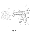
- Fig. 1 is an environmental, perspective view of an embodiment of a bioinjection device according to the present invention
- Fig. 2 is a side view of the bioinjection device of Fig. 1 shown broken away and partially in section to show details thereof;
- Fig. 3 is a perspective view of an embodiment of a membranous cartridge for use with a bioinjection device according to the present invention
- Fig. 4 is a partial side view in section of the bioinjection device of Fig. 1 of the drawings showing a cartridge extended from the device for injection or implantation;
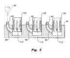
- Fig. 5 is a side view of an embodiment of a plurality of removable and fillable heads of a bioinjection device according to the present invention
- Fig. 6A is a perspective view of an alternative embodiment of a bioinjection device according to the present invention.
- Fig. 6B is a perspective view of another alternative embodiment of a bioinjection device according to the present invention.
- Fig. 7 is an exploded view of a plurality of alternative bone implants for use with the bioinjection device according to the present invention.
- Fig. 8 is a front view of a human leg broken away to show the bone implants of Fig. 7 inserted within a channel formed within a bone;
- Fig. 9 is a side view of an alternative embodiment of a head of the bioinjection device according to the present invention.
- Fig. 10 is a side view of another alternative embodiment of a bioinjection device according to the present invention.
- the present invention relates to a bioinjection device.
- a bioinjection device 10 As shown in Fig. 1 , an embodiment of a bioinjection device 10 is used to place a cartridge 12 into a fracture, degenerative tissue, or the like of a spinal segment S.
- the cartridge 12 contains a medicament (bone morphologic protein, antibiotics, or the like disposed in a bioabsorbable matrix or carrier) for the healing of the spinal segment S.
- a medicament bone morphologic protein, antibiotics, or the like disposed in a bioabsorbable matrix or carrier
- spinal segment S, having vertebral bodies V, disc D and facet joint F, of Fig. 1 is shown for exemplary purposes only and is not intended to limit the type of bone or fracture that the cartridge 12 and device 10 may be used to treat.
- the device 10 includes a housing 32 having a barrel-shaped upper portion 33 and a lower gripping portion 35.
- the lower gripping portion 35 may be rotatable with respect to the upper portion 33 and includes a pistol grip handle member 34 and a trigger member 36.
- the trigger member 36 is pivotally secured to the handle member 34 by a pivot pin 39 or the like.
- Trigger member 36 preferably has a plurality of finger receiving grooves or recesses 38 formed therein, as shown in Fig. 2 , allowing for optimal gripping and actuation by the surgeon.
- an upper gripping handle 11 may be mounted on an upper surface of housing 32, allowing the surgeon to better grip and secure tool 10 during the surgical operation.
- the lower portion 35 including both handle member 34 and trigger member 36, may be rotatable about pivot 37, allowing the lower gripping portion 35 to be rotated if necessary, depending upon the nature of the particular operation.
- the lower portion 35 may further be selectively locked in place with respect to the upper portion 33.
- the barrel-shaped upper portion 33 of housing 32 has an open interior region formed therein.
- a shaft 16 is slidably mounted within the open interior region of the upper portion 33 of the housing 32.
- the shaft has opposed forward and rear ends 21, 22, respectively, and is elongated along a longitudinal axis, as shown. Further, the shaft 16 has a longitudinally extending channel 25 formed therethrough, extending from the forward end 21 to the rear end 22.
- Shaft 16 is preferably resiliently or spring-biased with respect to housing 32.
- a stop 13 such as a disc, is mounted to a central portion of shaft 16, as shown in Fig. 2 , with a spring 20 or other resilient element being biased between the stop 13 and the inner wall of forward portion 50 of housing 32.
- At least one lever arm is pivotally mounted within housing 32 for the actuation of shaft 16.
- the at least one lever arm includes a pair of lever arms with a first lever arm 28 driving movement of the shaft 16, and a second lever arm 26 driving movement of needle 18, as will be described in greater detail below.
- First lever arm 28 has opposed first and second ends, with the first end of first lever arm 28 being secured to the rear end 22 of shaft 16, and the second end being secured to the trigger member 36 so that rotation of the trigger member 36 with respect to the handle member 34 drives sliding translation of the shaft 16 with respect to the upper portion 33 of the housing 32.
- Needle 18 is slidably received within the channel 25 formed through the shaft 16, with the needle 18 having opposed front and rear ends 27, 29, respectively (the front end or tip 27 of needle 18 8 is best shown in Fig. 4 ).
- the front end 27 of needle 18 is preferably formed as a relatively sharp point.
- the rear end 29 of needle 18 is secured at 24 to the second lever arm 26 so that rotation of trigger member 36 with respect to the handle member 34 drives forward sliding translation of the needle 18 with respect to the upper portion 33 of the housing 32 and also with respect to the shaft 16; i.e., actuation of trigger member 36 causes forward sliding of shaft 16 within the housing 32 and also forward sliding of needle 18 within the shaft 16.
- a retaining member 14 is further provided, with the retaining member having opposed front and rear ends. As shown, retaining member 14 preferably forms a pair of gripping jaws for releasably holding implant 12. The front end thereof is open and the rear end thereof is secured to mounting member 52, which is fixed to a forward portion 50 of the upper portion 33 of the housing 32.
- the rear portion of retaining member 14 is preferably releasably attached to the mounting member 52 through use of any suitable releasable fastener.
- the rear portion may have threads 58 formed thereon, as best shown in Fig. 4 , for reception by a threaded recess 53 formed in mounting member 52.
- an opening 19 is formed through the rear end of the retaining member 14, and a passage 17 is formed through the forward portion 50 of housing 32 so that the forward end 21 of shaft 16 and the front end 27 of the needle 18 selectively and slidably project therethrough into an open interior region of the retaining member 14.
- Cartridge 12 is releasably received within the open interior region of the retaining member 14.
- the cartridge 12 includes an outer shell membrane 40 and a medicament 42 contained within the outer shell 40.
- the medicament 42 may be a bone morphogenic protein, an antibiotic, or any other desired medicament for the healing of the bone, and may be disposed in a bioabsorbable matrix or carrier.
- the outer shell may be formed from hydroxyapatite calcium phosphate, or any other biodegradable material that will dissolve and/or fuse within the bone.
- the rear end 46 of shell 40 is formed as a relatively thin membrane that can be pierced by tip 27 of needle 18.
- a further thin membrane 44 may be formed between the outer shell 40 and the medicament 42.
- the cartridge 12 is positioned within retaining member 14, as shown in Fig. 2 , with the forward end 21 of shaft 16 contacting the rear surface 46 of the bone implant 12.
- Actuation of trigger member 36 causes the shaft 16 and the needle 18 to slide forward.
- Retaining member 14 is preferably formed from a flexible material, such as rubber, plastic or the like, so that forward movement of shaft 16 pushes the cartridge 12 out of the open front end of the retaining member 14 for deployment thereof into the bone fracture or other damaged or diseased area.
- the tip 27 of needle 18 pierces the thin membrane 46 to release the medicament 42 into the fracture. The surgeon lodges the pierced cartridge 12 within fracture F or the degenerative bone tissue.
- retaining member or head 14 of Fig. 4 has been replaced by an alternative head 214, having a rear portion 216 with threads 258, similar to threaded connection 58 of Fig. 4 .
- a pair of spring-biased jaws 218 are mounted to the rear portion 216, with one or both of the jaws 218 being adapted for releasably gripping a bone dowel 220 or the like for insertion into a facet joint FJ.
- the heads 14, 214 and the shaft have relatively small sizes, allowing for placement within the facet joint, as noted above.
- the head and/or shaft may have any suitable size, dependent upon the site for placement of the cartridge. As will be described in detail below, a longer shaft and head may be necessary for injection of cartridges within a larger or longer bone, such as a tibia, and the shaft and head may be appropriately sized dependent upon the intended injection site.
- Fig. 6A illustrates an alternative embodiment of a bioinjection device 100.
- Bioinjection device 100 includes a housing 132 having upper and lower portions 133, 135, similar to that of the embodiment of Figs. 1-4 .
- the lower portion 135 includes a handle member 134 and a trigger member 136
- the upper portion 133 has a handle 111 mounted thereon.
- Side handles 115 may also be mounted to upper portion 133, as shown, offering the surgeon a variety of gripping surfaces for differing angles of insertion during an operation.
- an elongated tube 114 is mounted to the front end of barrel-shaped upper portion 133, allowing for the implanting of bone implants where immediate proximity of the surgeon's hands is not possible, such as in the implantation of implants 112 within channel C formed in tibia T of Fig. 8 .
- the elongated tube 114 includes an adjustable portion 126, allowing for angular adjustment of the tube 114 adjacent the front end of the upper portion 133 of housing 132.
- Adjustable portion may be a rotating and selectively locking disc member, as shown, or may be any other suitable angular adjustment device.
- a central region 128, preferably being solid and relatively non-flexible, is joined to the flexible portions 126 at one end thereof, and a head 120 is disposed at the other end of tube 114. Head 120 has an open outer end with external threads 124 formed therearound.
- retaining jaws 14 of the embodiment of Figs. 1-5 are replaced in Fig. 6A by a cylindrical retaining member 130 having opposed open ends.
- Retaining member 130 is formed from a resilient, flexible material, similar to that described above with regard to jaws 14.
- Internal threads 140 are formed in one end of the retaining member 130 for releasable attachment to the head 120 via engagement with threads 124. It should be understood that retaining member 130 may be releasably secured to head 120 through any suitable releasable fastener.
- An implant 112 is received within retaining member 130 for selective dispensing thereof. Similar to that described above with regard to the embodiment of Figs. 1-5 , an inner shaft 116, similar to shaft 16, extends through tube 114 and is shown in Fig. 6A slightly projecting from head 120. Shaft 116 preferably has a plunger-type shape, as shown, with a relatively wide outer face for pushing the wider implant 112. A needle 118, similar to needle 18, is housed with in shaft 116.
- the alternative embodiment of Fig. 6B is substantially similar to that shown in Fig. 6A , but shaft 116 terminates in a covering head 117, which covers and surrounds the needle 118 and prevents the needle 118 from becoming caught in the implant 112.
- the user actuates trigger 136 to slide the shaft 116 and needle 118 forward so that the shaft 116 pushes the implant 112 out of retaining member 130 and needle 118 pierces the implant 112, as described above.
- trigger 136 When retaining member 130 is fixed to head 120, the head of plunger 116 will project out from retaining member 130 (when the trigger is compressed) by approximately one or two mm.
- Implant 112 is preferably formed from materials similar to those described above with reference to implant 12. However, as best shown in Fig. 7 , implant 112 preferably includes an upper projecting member 113 and a lower recess 114. As shown in Fig. 7 , multiple implants 112 may be stacked through insertion of an upper projecting member 113 into a lower recess 114 of an adjacent implant.
- the removable retaining members 130 may be stored and filled within a tray 54.
- cartridges 112 may be positioned within retaining members 130, as shown.
- Tray 54 preferably includes a plurality of channels 56 for filling of cartridges 112 within the stored retaining members 130.
- a syringe or other supply of medicament may be applied to ports 60, which cover and seal channels 56, allowing the medicament to be transferred to the cartridges 112. Communication with, and filling of, cartridges 112 may be accomplished through any suitable fluid transfer mechanism.
- Fig. 8 illustrates this stacked implantation within a channel C formed within an exemplary tibia T.
- Such channels C are often formed from the talus to the knee during the implantation of rods and the like in tibial reconstruction.
- the device 100 of Fig. 6 allows for easy insertion of multiple implants 112 within channel C after removal of such a rod.
- device 200 allows for manual insertion and operation of the implant 112.
- a gripping handle portion 204 is secured to a lower surface of mount 202.
- Hollow insertion tube 206 is mounted on a front portion of the upper surface of mount 202, as shown.
- the rear portion of the upper surface of mount 202 may have a groove, ridge or other means for slidably holding implant 112.
- a plunger 208 is provided, with plunger 208 having a gripping, rear portion and a front portion terminating in a plunger head 210, with needle 212 being positioned centrally therein.
- the user loads an implant 112 onto the rear, upper surface of mount 202, as shown, and pushes implant 112 through tube 206, for insertion, with plunger head 210 pushing implant through tube 206 and needle 212 piercing the rear end of implant 112, as described above.
Abstract
Description
- The present invention relates to devices for the delivery of pharmaceuticals, and particularly to a bioinjection device for delivering bone morphogenic protein, antibiotics, etc., directly to the site of a bone fracture, degenerative bone tissue or cartilage, etc., during the course of surgery in the form of a bioabsorbable matrix enclosed within a membrane cartridge.
- Bone is a living tissue and plays a structural role in the body. Disease and damage, however, is often difficult to treat in bones, due to their positioning within the soft tissues of the body. Bone consists of repeating Harvesian systems (concentric layers of lamellae deposited around a central canal containing blood vessels and nerves). The central canal is also known as the medullary cavity and is filled with bone marrow. Within the shaft of a long bone, many of these Harvesian systems are bundled together in parallel, forming a type of bone called compact bone, which is optimized to handle compressive and bending forces. In some bones, such as the metacarpals, for example, the bones themselves are hollow and contain little, if any, marrow. Near the ends of the bones, where the stresses become more complex, the Harvesian systems splay out and branch to form a meshwork of cancellous or spongy bone. Compact bone and cancellous bone differ in density, or how tightly the tissue is packed together.
- Genetic or developmental irregularities, trauma, chronic stress, tumors, and disease can result in pathologies of bones. Some bone diseases that weaken the bones include, but are not limited to, osteoporosis, achondroplasia, bone cancer, fibrodysplasia ossificans progressiva, fibrous dysplasia, legg calve perthes disease, myeloma, osteogenesis imperfecta, osteomyelitis, osteopenia, osteoporosis, Paget's disease, and scoliosis. Weakened bones are more susceptible to fracture, and treatment to prevent bone fractures becomes important. Severe fractures, such as those that are open, multiple, or to the hip or back, are typically treated in a hospital. Surgery may be necessary when a fracture is open, severe, or has resulted in severe injury to the surrounding tissues. Severe fractures may require internal devices, such as screws, rods, or plates, to hold the bone in place or replace lost bone during the healing process.
- In order to repair severe fractures, bone cement and the like is often applied within the fracture. However, other healing agents, such as antibiotics or bone morphogenic proteins, often need to be applied prior to cementing or performance of other operations on the bone. Due to the awkward positioning of bone fractures within other tissue, it is often quite difficult to properly apply medicaments and the like within the bone, particularly without damaging the tissue surrounding the bone. Thus, a bioinjection solving the aforementioned problems is desired.
- According to an aspect of the present invention, there is provided a bioinjection device as specified in
claim 1. According to another aspect of the present invention, there is provided a bioinjection device as specified in claim 9. According to a still further aspect of the present invention, there is provided a bioinjection device as specified inclaim 12. The invention is also directed to a method by which the described device(s) operate(s) and including method steps for carrying out every function of the device(s). - The bioinjection device is directed towards a device for injecting or implanting a membrane-encased cartridge of pharmaceuticals and/or biologics, bone grafts, radioactive seeds and the like, in a bioabsorbable matrix or carrier directly into the site of a bone fracture, degenerative bone tissue or cartilage, or the like in the course of surgery. The cartridge may contain bone morphogenic protein, antibiotics, bone, bone substitute or the like.
- The device includes a housing having an upper portion and a lower gripping portion. The lower gripping portion may be rotatable with respect to the upper portion and includes a handle member and a trigger member. The trigger member is pivotally secured to the handle member. Further, the upper portion of the housing has an open interior region formed therein.
- A shaft is slidably mounted within the open interior region of the upper portion of the housing. The shaft has opposed forward and rear ends and is elongated along a longitudinal axis. Further, the shaft has a channel formed therethrough, also extending along the longitudinal axis from the forward end to the rear end.
- At least one lever arm is pivotally mounted within the housing, with the at least one lever arm having opposed first and second ends. The first end of the lever arm is attached to the rear end of the shaft, and the second end is attached to the trigger member so that rotation of the trigger member with respect to the handle member drives sliding translation of the shaft with respect to the upper portion of the housing.
- A needle is slidable within the channel formed through the shaft, the needle having opposed front and rear ends. The front end of the needle terminates in a relatively sharp point. The rear end thereof is attached to the at least one lever arm so that rotation of the trigger member with respect to the handle member drives forward sliding translation of the needle with respect to the upper portion of the housing and the shaft. Preferably, the at least one lever arm includes a pair of lever arms, including a first lever arm driving movement of the shaft and a second lever arm driving movement of the needle.
- A retaining member has opposed front and rear ends. The front end is open and the rear end is attached to a forward portion of the upper portion of the housing. An opening is formed through the rear end of the retaining member and the forward portion of the upper portion so that the forward end of the shaft and the front end of the needle selectively and slidably project therethrough into an open interior region of the retaining member. The retaining member is preferably releasably attached to the forward portion of the upper portion of the housing.
- A cartridge is releasably received within the open interior region of the retaining member. The cartridge includes an outer shell membrane and a medicament contained within the outer shell. The forward end of the shaft contacts the membrane so that actuation of the trigger member causes the shaft and the needle to slide forward, with the shaft pushing the cartridge out of the retaining member for deployment thereof into the bone fracture. As the shaft pushes the implant out of the retaining member, the needle pierces the outer shell membrane to release the medicament into the fracture or degenerative tissue.
- These and other features of the present invention will become readily apparent upon further review of the following specification and drawings.
-
Fig. 1 is an environmental, perspective view of an embodiment of a bioinjection device according to the present invention; -
Fig. 2 is a side view of the bioinjection device ofFig. 1 shown broken away and partially in section to show details thereof; -
Fig. 3 is a perspective view of an embodiment of a membranous cartridge for use with a bioinjection device according to the present invention; -
Fig. 4 is a partial side view in section of the bioinjection device ofFig. 1 of the drawings showing a cartridge extended from the device for injection or implantation; -
Fig. 5 is a side view of an embodiment of a plurality of removable and fillable heads of a bioinjection device according to the present invention; -
Fig. 6A is a perspective view of an alternative embodiment of a bioinjection device according to the present invention; -
Fig. 6B is a perspective view of another alternative embodiment of a bioinjection device according to the present invention; -
Fig. 7 is an exploded view of a plurality of alternative bone implants for use with the bioinjection device according to the present invention; -
Fig. 8 is a front view of a human leg broken away to show the bone implants ofFig. 7 inserted within a channel formed within a bone; -
Fig. 9 is a side view of an alternative embodiment of a head of the bioinjection device according to the present invention; and -
Fig. 10 is a side view of another alternative embodiment of a bioinjection device according to the present invention. - Similar reference characters denote corresponding features consistently throughout the attached drawings.
- The present invention relates to a bioinjection device. As shown in
Fig. 1 , an embodiment of abioinjection device 10 is used to place acartridge 12 into a fracture, degenerative tissue, or the like of a spinal segment S. Thecartridge 12 contains a medicament (bone morphologic protein, antibiotics, or the like disposed in a bioabsorbable matrix or carrier) for the healing of the spinal segment S. It should be understood that spinal segment S, having vertebral bodies V, disc D and facet joint F, ofFig. 1 is shown for exemplary purposes only and is not intended to limit the type of bone or fracture that thecartridge 12 anddevice 10 may be used to treat. - As best shown in
Figs. 1 and2 , thedevice 10 includes ahousing 32 having a barrel-shapedupper portion 33 and a lower grippingportion 35. The lowergripping portion 35 may be rotatable with respect to theupper portion 33 and includes a pistolgrip handle member 34 and atrigger member 36. Thetrigger member 36 is pivotally secured to thehandle member 34 by apivot pin 39 or the like.Trigger member 36 preferably has a plurality of finger receiving grooves or recesses 38 formed therein, as shown inFig. 2 , allowing for optimal gripping and actuation by the surgeon. Further, an uppergripping handle 11 may be mounted on an upper surface ofhousing 32, allowing the surgeon to better grip andsecure tool 10 during the surgical operation. - As noted above, the
lower portion 35, including both handlemember 34 andtrigger member 36, may be rotatable aboutpivot 37, allowing the lower grippingportion 35 to be rotated if necessary, depending upon the nature of the particular operation. Thelower portion 35 may further be selectively locked in place with respect to theupper portion 33. Further, as shown inFig. 2 , the barrel-shapedupper portion 33 ofhousing 32 has an open interior region formed therein. - As shown in
Fig. 2 , ashaft 16 is slidably mounted within the open interior region of theupper portion 33 of thehousing 32. The shaft has opposed forward andrear ends shaft 16 has alongitudinally extending channel 25 formed therethrough, extending from theforward end 21 to therear end 22.Shaft 16 is preferably resiliently or spring-biased with respect tohousing 32. In the preferred embodiment, a stop 13, such as a disc, is mounted to a central portion ofshaft 16, as shown inFig. 2 , with aspring 20 or other resilient element being biased between the stop 13 and the inner wall offorward portion 50 ofhousing 32. - At least one lever arm is pivotally mounted within
housing 32 for the actuation ofshaft 16. Preferably, the at least one lever arm includes a pair of lever arms with afirst lever arm 28 driving movement of theshaft 16, and asecond lever arm 26 driving movement ofneedle 18, as will be described in greater detail below.First lever arm 28 has opposed first and second ends, with the first end offirst lever arm 28 being secured to therear end 22 ofshaft 16, and the second end being secured to thetrigger member 36 so that rotation of thetrigger member 36 with respect to thehandle member 34 drives sliding translation of theshaft 16 with respect to theupper portion 33 of thehousing 32. -
Needle 18 is slidably received within thechannel 25 formed through theshaft 16, with theneedle 18 having opposed front andrear ends tip 27 ofneedle 18 8 is best shown inFig. 4 ). Thefront end 27 ofneedle 18 is preferably formed as a relatively sharp point. Therear end 29 ofneedle 18 is secured at 24 to thesecond lever arm 26 so that rotation oftrigger member 36 with respect to thehandle member 34 drives forward sliding translation of theneedle 18 with respect to theupper portion 33 of thehousing 32 and also with respect to theshaft 16; i.e., actuation oftrigger member 36 causes forward sliding ofshaft 16 within thehousing 32 and also forward sliding ofneedle 18 within theshaft 16. - A retaining
member 14 is further provided, with the retaining member having opposed front and rear ends. As shown, retainingmember 14 preferably forms a pair of gripping jaws for releasably holdingimplant 12. The front end thereof is open and the rear end thereof is secured to mountingmember 52, which is fixed to aforward portion 50 of theupper portion 33 of thehousing 32. The rear portion of retainingmember 14 is preferably releasably attached to the mountingmember 52 through use of any suitable releasable fastener. The rear portion may havethreads 58 formed thereon, as best shown inFig. 4 , for reception by a threadedrecess 53 formed in mountingmember 52. - Further, an
opening 19 is formed through the rear end of the retainingmember 14, and apassage 17 is formed through theforward portion 50 ofhousing 32 so that theforward end 21 ofshaft 16 and thefront end 27 of theneedle 18 selectively and slidably project therethrough into an open interior region of the retainingmember 14. -
Cartridge 12 is releasably received within the open interior region of the retainingmember 14. As best shown inFig. 3 , thecartridge 12 includes anouter shell membrane 40 and amedicament 42 contained within theouter shell 40. Themedicament 42 may be a bone morphogenic protein, an antibiotic, or any other desired medicament for the healing of the bone, and may be disposed in a bioabsorbable matrix or carrier. The outer shell may be formed from hydroxyapatite calcium phosphate, or any other biodegradable material that will dissolve and/or fuse within the bone. Preferably, therear end 46 ofshell 40 is formed as a relatively thin membrane that can be pierced bytip 27 ofneedle 18. A furtherthin membrane 44 may be formed between theouter shell 40 and themedicament 42. - In use, the
cartridge 12 is positioned within retainingmember 14, as shown inFig. 2 , with theforward end 21 ofshaft 16 contacting therear surface 46 of thebone implant 12. Actuation oftrigger member 36 causes theshaft 16 and theneedle 18 to slide forward. Retainingmember 14 is preferably formed from a flexible material, such as rubber, plastic or the like, so that forward movement ofshaft 16 pushes thecartridge 12 out of the open front end of the retainingmember 14 for deployment thereof into the bone fracture or other damaged or diseased area. As theshaft 16 pushes thecartridge 12 out of the retainingmember 14, thetip 27 ofneedle 18 pierces thethin membrane 46 to release themedicament 42 into the fracture. The surgeon lodges thepierced cartridge 12 within fracture F or the degenerative bone tissue. - In
Fig. 9 , retaining member orhead 14 ofFig. 4 has been replaced by an alternative head 214, having arear portion 216 withthreads 258, similar to threadedconnection 58 ofFig. 4 . A pair of spring-biasedjaws 218 are mounted to therear portion 216, with one or both of thejaws 218 being adapted for releasably gripping abone dowel 220 or the like for insertion into a facet joint FJ. In the embodiments ofFigs. 2 and9 , theheads 14, 214 and the shaft have relatively small sizes, allowing for placement within the facet joint, as noted above. However, it should be understood that the head and/or shaft may have any suitable size, dependent upon the site for placement of the cartridge. As will be described in detail below, a longer shaft and head may be necessary for injection of cartridges within a larger or longer bone, such as a tibia, and the shaft and head may be appropriately sized dependent upon the intended injection site. -
Fig. 6A illustrates an alternative embodiment of abioinjection device 100.Bioinjection device 100 includes ahousing 132 having upper andlower portions Figs. 1-4 . Similarly, thelower portion 135 includes ahandle member 134 and atrigger member 136, and theupper portion 133 has ahandle 111 mounted thereon. Side handles 115 may also be mounted toupper portion 133, as shown, offering the surgeon a variety of gripping surfaces for differing angles of insertion during an operation. In the embodiment ofFig. 6A , anelongated tube 114 is mounted to the front end of barrel-shapedupper portion 133, allowing for the implanting of bone implants where immediate proximity of the surgeon's hands is not possible, such as in the implantation ofimplants 112 within channel C formed in tibia T ofFig. 8 . - The
elongated tube 114 includes anadjustable portion 126, allowing for angular adjustment of thetube 114 adjacent the front end of theupper portion 133 ofhousing 132. Adjustable portion may be a rotating and selectively locking disc member, as shown, or may be any other suitable angular adjustment device. Acentral region 128, preferably being solid and relatively non-flexible, is joined to theflexible portions 126 at one end thereof, and ahead 120 is disposed at the other end oftube 114.Head 120 has an open outer end withexternal threads 124 formed therearound. - The retaining
jaws 14 of the embodiment ofFigs. 1-5 are replaced inFig. 6A by acylindrical retaining member 130 having opposed open ends. Retainingmember 130 is formed from a resilient, flexible material, similar to that described above with regard tojaws 14.Internal threads 140 are formed in one end of the retainingmember 130 for releasable attachment to thehead 120 via engagement withthreads 124. It should be understood that retainingmember 130 may be releasably secured to head 120 through any suitable releasable fastener. - An
implant 112 is received within retainingmember 130 for selective dispensing thereof. Similar to that described above with regard to the embodiment ofFigs. 1-5 , aninner shaft 116, similar toshaft 16, extends throughtube 114 and is shown inFig. 6A slightly projecting fromhead 120.Shaft 116 preferably has a plunger-type shape, as shown, with a relatively wide outer face for pushing thewider implant 112. Aneedle 118, similar toneedle 18, is housed with inshaft 116. The alternative embodiment ofFig. 6B is substantially similar to that shown inFig. 6A , butshaft 116 terminates in acovering head 117, which covers and surrounds theneedle 118 and prevents theneedle 118 from becoming caught in theimplant 112. In operation, the user actuatestrigger 136 to slide theshaft 116 andneedle 118 forward so that theshaft 116 pushes theimplant 112 out of retainingmember 130 andneedle 118 pierces theimplant 112, as described above. When retainingmember 130 is fixed to head 120, the head ofplunger 116 will project out from retaining member 130 (when the trigger is compressed) by approximately one or two mm. -
Implant 112 is preferably formed from materials similar to those described above with reference toimplant 12. However, as best shown inFig. 7 ,implant 112 preferably includes an upper projectingmember 113 and alower recess 114. As shown inFig. 7 ,multiple implants 112 may be stacked through insertion of an upper projectingmember 113 into alower recess 114 of an adjacent implant. - As shown in
Fig. 5 , the removable retainingmembers 130 may be stored and filled within atray 54. In order to allow for quick insertion and replacement ofcartridges 112,cartridges 112 may be positioned within retainingmembers 130, as shown.Tray 54 preferably includes a plurality ofchannels 56 for filling ofcartridges 112 within the stored retainingmembers 130. A syringe or other supply of medicament may be applied toports 60, which cover and sealchannels 56, allowing the medicament to be transferred to thecartridges 112. Communication with, and filling of,cartridges 112 may be accomplished through any suitable fluid transfer mechanism. -
Fig. 8 illustrates this stacked implantation within a channel C formed within an exemplary tibia T. Such channels C are often formed from the talus to the knee during the implantation of rods and the like in tibial reconstruction. Thedevice 100 ofFig. 6 allows for easy insertion ofmultiple implants 112 within channel C after removal of such a rod. - In the alternative embodiment of
Fig. 10 ,device 200 allows for manual insertion and operation of theimplant 112. Agripping handle portion 204 is secured to a lower surface ofmount 202.Hollow insertion tube 206 is mounted on a front portion of the upper surface ofmount 202, as shown. The rear portion of the upper surface ofmount 202 may have a groove, ridge or other means for slidably holdingimplant 112. Aplunger 208 is provided, withplunger 208 having a gripping, rear portion and a front portion terminating in aplunger head 210, withneedle 212 being positioned centrally therein. In operation, the user loads animplant 112 onto the rear, upper surface ofmount 202, as shown, and pushesimplant 112 throughtube 206, for insertion, withplunger head 210 pushing implant throughtube 206 andneedle 212 piercing the rear end ofimplant 112, as described above. - It is to be understood that the present invention is not limited to the embodiments described above, but encompasses any and all embodiments within the scope of the following claims.
Claims (15)
- A bioinjection device, comprising:a housing having an upper portion and a lower gripping portion, the upper portion of the housing having an open interior region defined therein;a shaft slidably disposed in the open interior region of the upper portion of the housing, the shaft having a channel formed therethrough, said shaft having opposed forward and rear ends;means for selectively driving sliding translation of the shaft with respect to the upper portion of the housing;a needle slidably received within the channel formed through the shaft, the needle having opposed front and rear ends;means for selectively driving sliding translation of the needle with respect to the upper portion of the housing and the shaft;a retaining member having opposed front and rear ends, the front end being open, the rear end being attached to the upper portion of the housing, the rear end of the retaining member and the forward portion of the upper portion having an opening formed therein so that the forward end of the shaft and the front end of the needle selectively and slidably project the opening into the retaining member; anda bone implant having an outer shell and a medicament disposed in the outer shell, the bone implant being releasably disposed in the retaining member, the forward end of the shaft contacting the bone implant, whereby selective forward translation of the shaft and the needle causes the shaft to push the bone implant out of the retaining member for deployment into a bone, the needle piercing the outer shell to release the medicament.
- The bioinjection device as claimed in claim 1, wherein the lower gripping portion of said housing includes a handle member and a trigger member, the trigger member being pivotally attached to the handle member.
- The bioinjection device as claimed in claim 2, wherein the lower gripping portion is pivotal with respect to the upper portion.
- The bioinjection device as claimed in claim 2, wherein said means for selectively driving sliding translation of said shaft with respect to the upper portion of said housing comprises at least one lever arm having first and second ends, the first end being attached to the rear end of the shaft, the second end being attached to the trigger member so that rotation of the trigger member with respect to the handle member drives sliding translation of said shaft with respect to the upper portion of said housing.
- The bioinjection device as claimed in claim 4, wherein the rear end of said needle is attached to the at least one lever arm so that rotation of the trigger member with respect to the handle member drives forward sliding translation of said needle with respect to the upper portion of the housing and the shaft.
- The bioinjection device as claimed in claim 5, wherein said retaining member is releasably attached to the upper portion of said housing.
- The bioinjection device as claimed in any of claims 1-6, further comprising an upper handle mounted on said housing and, optionally, further comprising a side handle mounted on said housing.
- The bioinjection device as claimed in any of claims 1-7, wherein said bone implant has opposed forward and rear ends, the rear end being formed from a membranous material so that said needle pierces the membranous material to release the medicament and, optionally,
wherein the forward end of said bone implant forms an engaging member and the rear end has a recess defined therein so that a plurality of said bone implants may be stacked together, with the engaging member of one of said bone implants being received within a corresponding recess of an adjacent one of said bone implants. - A bioinjection device, comprising:a housing having a pistol grip and an elongated barrel mounted on the pistol grip, the barrel having a front end defining an opening;a trigger pivotally mounted on the housing;an elongated plunger having a sharp, pointed needle extending therefrom, the plunger being slidable between a first position in which the plunger and needle are retracted within the barrel and a second position in which the plunger and needle extend through the opening at the front end of the barrel;a retaining member disposed about the opening at the end of the barrel, the retaining member being adapted for loading a membranous cartridge containing a bone healing medicament therein; anda spring-biased actuation mechanism coupling the trigger with the plunger and the needle in order to eject the cartridge from the retaining member into bone tissue and pierce an outer membrane thereof to release the medicament into the bone tissue during surgery when the trigger is squeezed.
- The bioinjection device as claimed in claim 9, wherein the retaining member is releasably attached to the barrel.
- The bioinjection device as claimed in claim 9 or claim 10, wherein the spring-biased actuation mechanism comprises at least one lever arm having first and second ends, the first end being attached to the elongated plunger, the second end being attached to the trigger so that rotation of the trigger with respect to the pistol grip drives sliding translation of the elongated plunger with respect to the upper portion of the housing.
- A bioinjection device, comprising:a housing having an upper portion and a lower gripping portion, the lower gripping portion having a handle member and a trigger member, the trigger member being pivotally attached to the handle member, the upper portion of the housing having an open interior region defined therein;a shaft slidably mounted in the open interior region of the upper portion of the housing, the shaft having a channel formed therethrough, the shaft having opposed forward and rear ends;at least one lever arm having first and second ends, the first end being attached to the rear end of the shaft, the second end being attached to the trigger member so that rotation of the trigger member with respect to the handle member drives sliding translation of the shaft with respect to the upper portion of the housing;a needle slidably received within the channel formed through the shaft, the needle having opposed front and rear ends, the rear end of the needle being attached to the at least one lever arm so that rotation of the trigger member with respect to the handle member drives forward sliding translation of the needle with respect to the upper portion of the housing and the shaft;a retaining member having opposed front and rear ends, the front end being open, the rear end being attached to the upper portion of the housing, the rear end of the retaining member and the forward portion of the upper portion having an opening formed therein so that the forward end of the shaft and the front end of the needle selectively and slidably project therethrough and into an open interior region of the retaining member; anda bone implant having an outer shell and a medicament disposed in the outer shell, the bone implant being releasably disposed in the open interior region of the retaining member, the forward end of the shaft contacting the bone implant, whereby actuation of the trigger member causes the shaft and the needle to slide forward, the shaft pushing the bone implant out of the retaining member for deployment into a bone, the needle piercing the outer shell to release the medicament.
- The bioinjection device as claimed in claim 12, wherein said retaining member is releasably attached to the upper portion of said housing.
- The bioinjection device as claimed in claim 12 or claim 13, wherein the lower gripping portion of said housing is selectively rotatable with respect to the upper portion of said housing and, optionally, wherein the device further comprises(i) an upper handle mounted on said housing; or(ii) a side handle mounted on said housing; or(iii) an upper handle mounted on said housing and a side handle mounted on said housing.
- The bioinjection device as claimed in any of claims 12-14, wherein said bone implant has opposed forward and rear ends, the rear end being formed from a membranous material so that said needle pierces the membranous material to release the medicament, and, optionally, wherein the forward end of said bone implant forms an engaging member and the rear end has a recess defined therein so that a plurality of said bone implants may be stacked together with the engaging member of one of said bone implants being received within a corresponding recess of an adjacent one of said bone implants.
Priority Applications (2)
| Application Number | Priority Date | Filing Date | Title |
|---|---|---|---|
| EP20100150380 EP2343100B1 (en) | 2010-01-08 | 2010-01-08 | Bioinjection device |
| ES10150380T ES2395371T3 (en) | 2010-01-08 | 2010-01-08 | Bioinjection device |
Applications Claiming Priority (1)
| Application Number | Priority Date | Filing Date | Title |
|---|---|---|---|
| EP20100150380 EP2343100B1 (en) | 2010-01-08 | 2010-01-08 | Bioinjection device |
Publications (2)
| Publication Number | Publication Date |
|---|---|
| EP2343100A1 true EP2343100A1 (en) | 2011-07-13 |
| EP2343100B1 EP2343100B1 (en) | 2012-09-12 |
Family
ID=42173915
Family Applications (1)
| Application Number | Title | Priority Date | Filing Date |
|---|---|---|---|
| EP20100150380 Active EP2343100B1 (en) | 2010-01-08 | 2010-01-08 | Bioinjection device |
Country Status (2)
| Country | Link |
|---|---|
| EP (1) | EP2343100B1 (en) |
| ES (1) | ES2395371T3 (en) |
Cited By (1)
| Publication number | Priority date | Publication date | Assignee | Title |
|---|---|---|---|---|
| WO2015112351A1 (en) * | 2014-01-24 | 2015-07-30 | Covidien Lp | Directional subintimal access for chemical agent delivery |
Citations (3)
| Publication number | Priority date | Publication date | Assignee | Title |
|---|---|---|---|---|
| US4578061A (en) * | 1980-10-28 | 1986-03-25 | Lemelson Jerome H | Injection catheter and method |
| WO2002007786A2 (en) * | 2000-07-24 | 2002-01-31 | Elliott James B | Apparatus and method for introducing an implant |
| US6939318B2 (en) * | 2002-05-03 | 2005-09-06 | Boston Scientific Scimed, Inc. | Method, tool, and system for deploying an implant into the body |
-
2010
- 2010-01-08 ES ES10150380T patent/ES2395371T3/en active Active
- 2010-01-08 EP EP20100150380 patent/EP2343100B1/en active Active
Patent Citations (3)
| Publication number | Priority date | Publication date | Assignee | Title |
|---|---|---|---|---|
| US4578061A (en) * | 1980-10-28 | 1986-03-25 | Lemelson Jerome H | Injection catheter and method |
| WO2002007786A2 (en) * | 2000-07-24 | 2002-01-31 | Elliott James B | Apparatus and method for introducing an implant |
| US6939318B2 (en) * | 2002-05-03 | 2005-09-06 | Boston Scientific Scimed, Inc. | Method, tool, and system for deploying an implant into the body |
Cited By (1)
| Publication number | Priority date | Publication date | Assignee | Title |
|---|---|---|---|---|
| WO2015112351A1 (en) * | 2014-01-24 | 2015-07-30 | Covidien Lp | Directional subintimal access for chemical agent delivery |
Also Published As
| Publication number | Publication date |
|---|---|
| EP2343100B1 (en) | 2012-09-12 |
| ES2395371T3 (en) | 2013-02-12 |
Similar Documents
| Publication | Publication Date | Title |
|---|---|---|
| US9387290B2 (en) | Bioinjection device | |
| US11666455B2 (en) | Bone graft delivery devices, systems and kits | |
| US11497539B2 (en) | Bone graft delivery system and method for using same | |
| US10195053B2 (en) | Bone graft delivery system and method for using same | |
| US9629729B2 (en) | Biological delivery system with adaptable fusion cage interface | |
| KR101142110B1 (en) | A medical treatment material delivery apparatus | |
| US11660208B2 (en) | Bone graft delivery system and method for using same | |
| US20080015705A1 (en) | Magazine Containing Marking Bodies for Implantation | |
| US20230059830A1 (en) | Bone graft delivery systems and methods for using same | |
| EP2343100B1 (en) | Bioinjection device | |
| WO2015061137A1 (en) | Bioinjection device having a tip with a plurality of directional dispersion apertures | |
| EP3357459A1 (en) | Bone graft delivery device with positioning handle |
Legal Events
| Date | Code | Title | Description |
|---|---|---|---|
| PUAI | Public reference made under article 153(3) epc to a published international application that has entered the european phase |
Free format text: ORIGINAL CODE: 0009012 |
|
| AK | Designated contracting states |
Kind code of ref document: A1 Designated state(s): AT BE BG CH CY CZ DE DK EE ES FI FR GB GR HR HU IE IS IT LI LT LU LV MC MK MT NL NO PL PT RO SE SI SK SM TR |
|
| AX | Request for extension of the european patent |
Extension state: AL BA RS |
|
| 17P | Request for examination filed |
Effective date: 20120113 |
|
| GRAP | Despatch of communication of intention to grant a patent |
Free format text: ORIGINAL CODE: EPIDOSNIGR1 |
|
| GRAS | Grant fee paid |
Free format text: ORIGINAL CODE: EPIDOSNIGR3 |
|
| GRAA | (expected) grant |
Free format text: ORIGINAL CODE: 0009210 |
|
| AK | Designated contracting states |
Kind code of ref document: B1 Designated state(s): AT BE BG CH CY CZ DE DK EE ES FI FR GB GR HR HU IE IS IT LI LT LU LV MC MK MT NL NO PL PT RO SE SI SK SM TR |
|
| AX | Request for extension of the european patent |
Extension state: AL BA RS |
|
| REG | Reference to a national code |
Ref country code: GB Ref legal event code: FG4D |
|
| REG | Reference to a national code |
Ref country code: CH Ref legal event code: EP |
|
| REG | Reference to a national code |
Ref country code: AT Ref legal event code: REF Ref document number: 574747 Country of ref document: AT Kind code of ref document: T Effective date: 20120915 |
|
| REG | Reference to a national code |
Ref country code: IE Ref legal event code: FG4D |
|
| REG | Reference to a national code |
Ref country code: DE Ref legal event code: R096 Ref document number: 602010002733 Country of ref document: DE Effective date: 20121108 |
|
| REG | Reference to a national code |
Ref country code: NL Ref legal event code: T3 |
|
| PG25 | Lapsed in a contracting state [announced via postgrant information from national office to epo] |
Ref country code: NO Free format text: LAPSE BECAUSE OF FAILURE TO SUBMIT A TRANSLATION OF THE DESCRIPTION OR TO PAY THE FEE WITHIN THE PRESCRIBED TIME-LIMIT Effective date: 20121212 Ref country code: LT Free format text: LAPSE BECAUSE OF FAILURE TO SUBMIT A TRANSLATION OF THE DESCRIPTION OR TO PAY THE FEE WITHIN THE PRESCRIBED TIME-LIMIT Effective date: 20120912 Ref country code: FI Free format text: LAPSE BECAUSE OF FAILURE TO SUBMIT A TRANSLATION OF THE DESCRIPTION OR TO PAY THE FEE WITHIN THE PRESCRIBED TIME-LIMIT Effective date: 20120912 Ref country code: HR Free format text: LAPSE BECAUSE OF FAILURE TO SUBMIT A TRANSLATION OF THE DESCRIPTION OR TO PAY THE FEE WITHIN THE PRESCRIBED TIME-LIMIT Effective date: 20120912 |
|
| REG | Reference to a national code |
Ref country code: ES Ref legal event code: FG2A Ref document number: 2395371 Country of ref document: ES Kind code of ref document: T3 Effective date: 20130212 |
|
| REG | Reference to a national code |
Ref country code: AT Ref legal event code: MK05 Ref document number: 574747 Country of ref document: AT Kind code of ref document: T Effective date: 20120912 |
|
| REG | Reference to a national code |
Ref country code: LT Ref legal event code: MG4D Effective date: 20120912 |
|
| PG25 | Lapsed in a contracting state [announced via postgrant information from national office to epo] |
Ref country code: SE Free format text: LAPSE BECAUSE OF FAILURE TO SUBMIT A TRANSLATION OF THE DESCRIPTION OR TO PAY THE FEE WITHIN THE PRESCRIBED TIME-LIMIT Effective date: 20120912 Ref country code: GR Free format text: LAPSE BECAUSE OF FAILURE TO SUBMIT A TRANSLATION OF THE DESCRIPTION OR TO PAY THE FEE WITHIN THE PRESCRIBED TIME-LIMIT Effective date: 20121213 Ref country code: LV Free format text: LAPSE BECAUSE OF FAILURE TO SUBMIT A TRANSLATION OF THE DESCRIPTION OR TO PAY THE FEE WITHIN THE PRESCRIBED TIME-LIMIT Effective date: 20120912 Ref country code: SI Free format text: LAPSE BECAUSE OF FAILURE TO SUBMIT A TRANSLATION OF THE DESCRIPTION OR TO PAY THE FEE WITHIN THE PRESCRIBED TIME-LIMIT Effective date: 20120912 |
|
| PG25 | Lapsed in a contracting state [announced via postgrant information from national office to epo] |
Ref country code: IS Free format text: LAPSE BECAUSE OF FAILURE TO SUBMIT A TRANSLATION OF THE DESCRIPTION OR TO PAY THE FEE WITHIN THE PRESCRIBED TIME-LIMIT Effective date: 20130112 Ref country code: EE Free format text: LAPSE BECAUSE OF FAILURE TO SUBMIT A TRANSLATION OF THE DESCRIPTION OR TO PAY THE FEE WITHIN THE PRESCRIBED TIME-LIMIT Effective date: 20120912 Ref country code: BE Free format text: LAPSE BECAUSE OF FAILURE TO SUBMIT A TRANSLATION OF THE DESCRIPTION OR TO PAY THE FEE WITHIN THE PRESCRIBED TIME-LIMIT Effective date: 20120912 Ref country code: RO Free format text: LAPSE BECAUSE OF FAILURE TO SUBMIT A TRANSLATION OF THE DESCRIPTION OR TO PAY THE FEE WITHIN THE PRESCRIBED TIME-LIMIT Effective date: 20120912 Ref country code: CZ Free format text: LAPSE BECAUSE OF FAILURE TO SUBMIT A TRANSLATION OF THE DESCRIPTION OR TO PAY THE FEE WITHIN THE PRESCRIBED TIME-LIMIT Effective date: 20120912 |
|
| PG25 | Lapsed in a contracting state [announced via postgrant information from national office to epo] |
Ref country code: PT Free format text: LAPSE BECAUSE OF FAILURE TO SUBMIT A TRANSLATION OF THE DESCRIPTION OR TO PAY THE FEE WITHIN THE PRESCRIBED TIME-LIMIT Effective date: 20130114 Ref country code: PL Free format text: LAPSE BECAUSE OF FAILURE TO SUBMIT A TRANSLATION OF THE DESCRIPTION OR TO PAY THE FEE WITHIN THE PRESCRIBED TIME-LIMIT Effective date: 20120912 Ref country code: SK Free format text: LAPSE BECAUSE OF FAILURE TO SUBMIT A TRANSLATION OF THE DESCRIPTION OR TO PAY THE FEE WITHIN THE PRESCRIBED TIME-LIMIT Effective date: 20120912 |
|
| PG25 | Lapsed in a contracting state [announced via postgrant information from national office to epo] |
Ref country code: AT Free format text: LAPSE BECAUSE OF FAILURE TO SUBMIT A TRANSLATION OF THE DESCRIPTION OR TO PAY THE FEE WITHIN THE PRESCRIBED TIME-LIMIT Effective date: 20120912 |
|
| PLBE | No opposition filed within time limit |
Free format text: ORIGINAL CODE: 0009261 |
|
| STAA | Information on the status of an ep patent application or granted ep patent |
Free format text: STATUS: NO OPPOSITION FILED WITHIN TIME LIMIT |
|
| PG25 | Lapsed in a contracting state [announced via postgrant information from national office to epo] |
Ref country code: BG Free format text: LAPSE BECAUSE OF FAILURE TO SUBMIT A TRANSLATION OF THE DESCRIPTION OR TO PAY THE FEE WITHIN THE PRESCRIBED TIME-LIMIT Effective date: 20121212 Ref country code: DK Free format text: LAPSE BECAUSE OF FAILURE TO SUBMIT A TRANSLATION OF THE DESCRIPTION OR TO PAY THE FEE WITHIN THE PRESCRIBED TIME-LIMIT Effective date: 20120912 |
|
| 26N | No opposition filed |
Effective date: 20130613 |
|
| PG25 | Lapsed in a contracting state [announced via postgrant information from national office to epo] |
Ref country code: MC Free format text: LAPSE BECAUSE OF NON-PAYMENT OF DUE FEES Effective date: 20130131 |
|
| REG | Reference to a national code |
Ref country code: DE Ref legal event code: R097 Ref document number: 602010002733 Country of ref document: DE Effective date: 20130613 |
|
| PG25 | Lapsed in a contracting state [announced via postgrant information from national office to epo] |
Ref country code: CY Free format text: LAPSE BECAUSE OF FAILURE TO SUBMIT A TRANSLATION OF THE DESCRIPTION OR TO PAY THE FEE WITHIN THE PRESCRIBED TIME-LIMIT Effective date: 20120912 |
|
| PG25 | Lapsed in a contracting state [announced via postgrant information from national office to epo] |
Ref country code: MT Free format text: LAPSE BECAUSE OF FAILURE TO SUBMIT A TRANSLATION OF THE DESCRIPTION OR TO PAY THE FEE WITHIN THE PRESCRIBED TIME-LIMIT Effective date: 20120912 |
|
| PG25 | Lapsed in a contracting state [announced via postgrant information from national office to epo] |
Ref country code: SM Free format text: LAPSE BECAUSE OF FAILURE TO SUBMIT A TRANSLATION OF THE DESCRIPTION OR TO PAY THE FEE WITHIN THE PRESCRIBED TIME-LIMIT Effective date: 20120912 |
|
| PG25 | Lapsed in a contracting state [announced via postgrant information from national office to epo] |
Ref country code: TR Free format text: LAPSE BECAUSE OF FAILURE TO SUBMIT A TRANSLATION OF THE DESCRIPTION OR TO PAY THE FEE WITHIN THE PRESCRIBED TIME-LIMIT Effective date: 20120912 |
|
| PG25 | Lapsed in a contracting state [announced via postgrant information from national office to epo] |
Ref country code: HU Free format text: LAPSE BECAUSE OF FAILURE TO SUBMIT A TRANSLATION OF THE DESCRIPTION OR TO PAY THE FEE WITHIN THE PRESCRIBED TIME-LIMIT; INVALID AB INITIO Effective date: 20100108 Ref country code: MK Free format text: LAPSE BECAUSE OF FAILURE TO SUBMIT A TRANSLATION OF THE DESCRIPTION OR TO PAY THE FEE WITHIN THE PRESCRIBED TIME-LIMIT Effective date: 20120912 |
|
| REG | Reference to a national code |
Ref country code: FR Ref legal event code: PLFP Year of fee payment: 7 |
|
| REG | Reference to a national code |
Ref country code: FR Ref legal event code: PLFP Year of fee payment: 8 |
|
| REG | Reference to a national code |
Ref country code: FR Ref legal event code: PLFP Year of fee payment: 9 |
|
| P01 | Opt-out of the competence of the unified patent court (upc) registered |
Effective date: 20230512 |
|
| PGFP | Annual fee paid to national office [announced via postgrant information from national office to epo] |
Ref country code: NL Payment date: 20230720 Year of fee payment: 14 Ref country code: LU Payment date: 20230720 Year of fee payment: 14 |
|
| PGFP | Annual fee paid to national office [announced via postgrant information from national office to epo] |
Ref country code: IT Payment date: 20230726 Year of fee payment: 14 Ref country code: IE Payment date: 20230720 Year of fee payment: 14 Ref country code: GB Payment date: 20230720 Year of fee payment: 14 Ref country code: ES Payment date: 20230717 Year of fee payment: 14 Ref country code: CH Payment date: 20230724 Year of fee payment: 14 |
|
| PGFP | Annual fee paid to national office [announced via postgrant information from national office to epo] |
Ref country code: FR Payment date: 20230720 Year of fee payment: 14 Ref country code: DE Payment date: 20230720 Year of fee payment: 14 |