EP2335615A1 - Wireless surgical clip counter - Google Patents
Wireless surgical clip counter Download PDFInfo
- Publication number
- EP2335615A1 EP2335615A1 EP10251737A EP10251737A EP2335615A1 EP 2335615 A1 EP2335615 A1 EP 2335615A1 EP 10251737 A EP10251737 A EP 10251737A EP 10251737 A EP10251737 A EP 10251737A EP 2335615 A1 EP2335615 A1 EP 2335615A1
- Authority
- EP
- European Patent Office
- Prior art keywords
- clips
- clip
- housing
- channel
- counter
- Prior art date
- Legal status (The legal status is an assumption and is not a legal conclusion. Google has not performed a legal analysis and makes no representation as to the accuracy of the status listed.)
- Withdrawn
Links
Images


Classifications
-
- A—HUMAN NECESSITIES
- A61—MEDICAL OR VETERINARY SCIENCE; HYGIENE
- A61B—DIAGNOSIS; SURGERY; IDENTIFICATION
- A61B17/00—Surgical instruments, devices or methods, e.g. tourniquets
- A61B17/12—Surgical instruments, devices or methods, e.g. tourniquets for ligaturing or otherwise compressing tubular parts of the body, e.g. blood vessels, umbilical cord
- A61B17/128—Surgical instruments, devices or methods, e.g. tourniquets for ligaturing or otherwise compressing tubular parts of the body, e.g. blood vessels, umbilical cord for applying or removing clamps or clips
- A61B17/1285—Surgical instruments, devices or methods, e.g. tourniquets for ligaturing or otherwise compressing tubular parts of the body, e.g. blood vessels, umbilical cord for applying or removing clamps or clips for minimally invasive surgery
-
- A—HUMAN NECESSITIES
- A61—MEDICAL OR VETERINARY SCIENCE; HYGIENE
- A61B—DIAGNOSIS; SURGERY; IDENTIFICATION
- A61B17/00—Surgical instruments, devices or methods, e.g. tourniquets
- A61B2017/00367—Details of actuation of instruments, e.g. relations between pushing buttons, or the like, and activation of the tool, working tip, or the like
- A61B2017/00407—Ratchet means
-
- A—HUMAN NECESSITIES
- A61—MEDICAL OR VETERINARY SCIENCE; HYGIENE
- A61B—DIAGNOSIS; SURGERY; IDENTIFICATION
- A61B18/00—Surgical instruments, devices or methods for transferring non-mechanical forms of energy to or from the body
- A61B2018/00988—Means for storing information, e.g. calibration constants, or for preventing excessive use, e.g. usage, service life counter
-
- A—HUMAN NECESSITIES
- A61—MEDICAL OR VETERINARY SCIENCE; HYGIENE
- A61B—DIAGNOSIS; SURGERY; IDENTIFICATION
- A61B90/00—Instruments, implements or accessories specially adapted for surgery or diagnosis and not covered by any of the groups A61B1/00 - A61B50/00, e.g. for luxation treatment or for protecting wound edges
- A61B90/03—Automatic limiting or abutting means, e.g. for safety
- A61B2090/038—Automatic limiting or abutting means, e.g. for safety during shipment
-
- A—HUMAN NECESSITIES
- A61—MEDICAL OR VETERINARY SCIENCE; HYGIENE
- A61B—DIAGNOSIS; SURGERY; IDENTIFICATION
- A61B90/00—Instruments, implements or accessories specially adapted for surgery or diagnosis and not covered by any of the groups A61B1/00 - A61B50/00, e.g. for luxation treatment or for protecting wound edges
- A61B90/08—Accessories or related features not otherwise provided for
- A61B2090/0803—Counting the number of times an instrument is used
Definitions
- the present application relates to surgical instruments, and more particularly, to a surgical clip applier having a transmitter and remote display to count the number of clips in the surgical clip applier.
- Surgical clip appliers are known in the art and have increased in popularity among surgeons by offering an alternative to conventional suturing of body tissues and vessels.
- Typical instruments are disclosed in U.S. Pat. No. 5,030,226 to Green et al. and U.S. Pat. No. 5,431,668 to Burbank III et al. These instruments generally provide a plurality of clips which are stored in the instrument and which are fed sequentially to the jaw mechanism at the distal end of the instrument upon opening and closing of the handles at the proximal end of the instrument. As the handles are closed, the jaws close to deform a clip positioned between the jaw members, and as the jaws are opened to release the deformed clip, a new clip is fed from the series to a position between the jaws. This process is repeated until all the clips in the series of clips have been used.
- Endoscopic clip appliers are also known in the art for applying a single clip during an entry to the body cavity. Such single clip appliers are typically fabricated from a biocompatible material and are usually compressed over a vessel. Once applied to the vessel, the compressed clip terminates the flow of fluid therethrough. Endoscopic clip appliers that are able to apply multiple clips in endoscopic or laparoscopic procedures during a single entry into the body cavity are described in commonly-assigned U.S. Pat. Nos. 5,084,057 and 5,100,420 to Green et al. , which are both incorporated by reference in their entirety. Another multiple endoscopic clip applier is disclosed in commonly-assigned U.S. Pat. No. 5,607,436 to Pratt et al.
- Clip applier or endoscopic clip appliers have a built in counter and display to provide such an indication. Due to the size of the clip appliers, the size of the display may be relatively small.
- the present disclosure relates to novel surgical clip appliers.
- a surgical clip applier including a housing; at least one handle pivotably connected to the housing; a channel assembly extending from the housing; a clip carrier disposed within the channel assembly and defining a channel and a plurality of windows therein; a plurality of clips slidably disposed within the channel of the clip carrier; and a counter mechanism supported in at least one of the housing and the channel assembly, wherein the counter mechanism is configured to transmit a change in status of the apparatus upon each actuation of the at least one handle.
- the counter mechanism includes a switch configured to output a signal upon actuation of the at least one handle; an encoder configured to output a bit sequence upon actuation of the switch; a radio frequency transmitted operable to convert the bit sequence into a radio frequency signal; and a transmitting antenna configured to transmit the radio frequency signal.
- an apparatus for application of surgical clips to body tissue includes a handle assembly having a trigger; a shaft assembly extending distally from the handle assembly and defining a longitudinal axis; a plurality of surgical clips disposed within the shaft assembly; a jaw mounted adjacent a distal end portion of the shaft assembly, the jaw being movable between an open spaced-apart condition and a closed approximated condition; and a counter mechanism supported in the handle assembly, wherein the counter mechanism provides an indication when a surgical clip has been fired upon activation of the trigger.
- the counter mechanism includes a switch configured to output a signal upon actuation of the trigger; an encoder configured to output a bit sequence upon actuation of the switch; a radio frequency transmitted operable to convert the bit sequence into a radio frequency signal; and a transmitting antenna configured to transmit the radio frequency signal.
- a display unit includes a receiver configured to receive a radio frequency signal from the clip applier; a decoder configured to decode the radio frequency signal; a counter configured to provide a count of a number of clips; and a display driver operable to control a display based on the count provided by the counter.
- the counter is a binary coded decimal counter that provides a binary coded signal to the display driver.
- the counter decrements the count of the number of clips when the receiver receives a radio frequency signal from the clip applier.
- the counter may also increment the count of the number of clips when the receiver receives a radio frequency signal from the clip applier.
- the display has at least one seven segment light emitting diode.
- the display unit further includes a a power on reset switch configured to reset the display when the count reaches a predetermined number.
- a system for application of surgical clips to body tissue includes an apparatus for applying the surgical clip and a display unit configured receive the change in status of the apparatus upon each actuation of the at least one handle and display a count of the number of clips based on the change in status.
- the apparatus includes a housing; at least one handle pivotably connected to the housing; a channel assembly extending distally from the housing; a clip carrier disposed within the channel assembly and defining a channel and a plurality of windows therein; a plurality of clips slidably disposed within the channel of the clip carrier; and a counter mechanism supported in at least one of the housing and the channel assembly, wherein the counter mechanism is configured to transmit a change in status of the apparatus upon each actuation of the at least one handle.
- a system for application of surgical clips to body tissue includes an apparatus for applying the surgical clip and a display unit configured receive the change in status of the apparatus upon each actuation of the at least one handle and display a count of the number of clips based on the change in status.
- the apparatus includes a handle assembly having a trigger; a shaft assembly including a housing extending distally from the handle assembly and defining a longitudinal axis; a plurality of surgical clips disposed within the shaft assembly; a jaw mounted adjacent a distal end portion of the shaft assembly, the jaw being movable between an open spaced-apart condition and a closed approximated condition; and a counter mechanism supported in the handle assembly, wherein the counter mechanism provides an indication when a surgical clip has been fired upon activation of the trigger.
- the display unit displays a number of clips remaining in the apparatus or the number of clips applied by the apparatus.
- FIG. 1 is a perspective view of a surgical clip applier according to an embodiment of the present disclosure
- FIG. 1A is a rear, perspective view of the surgical clip applier of FIG. 1 , shown with a shipping wedge in position;
- FIG. 1B is a cross-sectional view as taken through 1B-1B of FIG. 1A ;
- FIG. 1C is a cross-sectional view as taken through 1C-1C of FIG. 1A ;
- FIG. 2 is a top, plan view of the surgical clip applier of FIG. 1 ;
- FIG. 3 is a side, elevational view of the surgical clip applier of FIGS. 1 and 2 ;
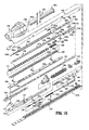
- FIG. 4 is an exploded perspective view of the surgical clip applier of FIGS. 1-3 ;
- FIG. 4A is an exploded perspective view of a bell crank gear and accelerator rack assembly of the surgical clip applier of FIGS. 1-4 ;
- FIG. 4B is a perspective view of the accelerator rack of the surgical clip applier of FIGS. 1-4 ;
- FIG. 4C is a view of the bell crank gear of the surgical clip applier of FIGS. 1-4 ;
- FIG. 4D is a top, perspective view of a pivot arm of the surgical clip applier of FIGS. 1-4 ;
- FIG. 4E is a bottom, perspective view of the pivot arm of FIG. 4D ;
- FIG. 4F is a top, perspective view of a clip follower of the surgical clip applier of FIGS. 1-4 ;
- FIG. 4G is a perspective view of an audible/tactile indicator of the surgical clip applier of FIGS. 1-4 ;
- FIG. 4H is a perspective view of a rack member of the surgical clip applier of FIGS. 1-4 ;
- FIG. 5 is a longitudinal cross-sectional view of the surgical clip applier of FIGS. 1-4 , illustrating the surgical clip applier in an unactuated condition;
- FIG. 6 is an enlarged view of the indicated area of detail of FIG. 5 ;
- FIG. 7 is an enlarged, cross-sectional view illustrating an actuation of a counter mechanism of the surgical clip applier of FIGS. 1-3 ;
- FIG. 8 is a front, perspective view of a surgical clip applier according to another embodiment of the present disclosure.
- FIG. 9 is a rear, perspective view of the clip applier of FIG. 8 illustrating a rotation of a shaft assembly thereof;
- FIG. 10 is a front, perspective view of a distal end of the shaft assembly of the clip applier of FIGS. 8 and 9 ;
- FIG. 11 is a top, plan view of the clip applier of FIGS. 8 and 9 ;
- FIG. 12 is a side, elevational view of the clip applier of FIGS. 8 and 9 ;
- FIG. 13 is a perspective view of a handle assembly of the clip applier of FIG. 8-12 , illustrated with a left side housing half-section removed therefrom;
- FIG. 14 is a perspective view of a handle assembly of the clip applier of FIG. 8-12 , illustrated with a right side housing half-section removed therefrom;
- FIG. 15 is a perspective view, with parts separated, of the handle assembly of the clip applier of FIGS. 8-12 ;
- FIG. 15A is a perspective view of the handle assembly of FIGS. 13-15 , with a trigger removed therefrom;
- FIG. 15B is a perspective view of a feedback member of the handle assembly of FIGS. 13-15 ;
- FIG. 16 is a perspective view, with parts separated, of the shaft assembly of the clip applier of FIGS. 8-12 ;
- FIG. 17 is a schematic block diagram of a counter mechanism of the surgical clip applier
- FIG. 18 is a schematic block diagram of a remote display associated with the surgical clip applier.
- FIG. 19 is a front view illustrating the remote display of FIG. 18 .
- proximal refers to the end of the apparatus which is closer to the user and the term “distal” refers to the end of the apparatus which is further away from the user.
- Surgical clip applier 100 generally includes a handle assembly 102 including a housing 104 having an upper housing half 104a and lower housing half 104b. Handle assembly 102 further includes a pair of handles 106 pivotably secured to housing 104 and extending outwardly therefrom. A channel assembly 108 is fixedly secured to housing 104 and extends outwardly therefrom, terminating in a jaw assembly 110.
- housing halves 104a and 104b of clip applier 100 fit together by snap fit engagement with one another.
- Housing 104 defines a window 104c formed in lower housing half 104b for supporting a counter mechanism 190, as will be discussed in greater detail below with reference to FIG. 17 .
- Housing 104 is formed of a suitable plastic material.
- handles 106 are secured to housing 104 by handle pivot posts 104d extending from lower housing half 104b and into respective apertures 106a formed in handles 106.
- Handle assembly 102 includes a link member 122 pivotally connected to each handle 106 at a pivot point 106b formed in a respective handle 106.
- a distal end 122a of each link member 122 is pivotally connected to a pivot point 140a formed in a drive channel 140 via a drive pin 124.
- Each end of drive pin 124 is slidably received in an elongate channel 104e formed in a respective upper and lower housing half 104a, 104b.
- Channel assembly 108 includes a channel or cartridge cover 130 and an outer or lower channel 132 each having a proximal end retained in housing assembly 102, between upper and lower housing halves 104a, 104b.
- Cartridge cover 130 includes at least one retention element 130a configured and adapted to selectively engage, in a snap-fit engagement, a complementary or corresponding retention element 132a provided on outer channel 132.
- clip applier 100 includes a clip pusher bar 160 slidably disposed beneath cartridge cover 130.
- Pusher bar 160 includes a distal end 160a defining a pusher 160c configured and adapted to selectively engage/move a distal-most clip "C1" stored in surgical clip applier 100.
- Pusher bar 160 further includes a proximal end 160b defining a proximal window 160d therein for slidably receiving drive pin 124 therein.
- Pusher bar 160 further defines a distal window 160e therein for operative engagement with a stabilizer 162, as will be discussed in greater detail below.
- Pusher bar 160 also includes a fin 160f projecting from a side edge thereof and located in relative close proximity to proximal window 160d.
- Clip applier 100 further includes a stabilizer 162 configured to overlie and engage pusher bar 160.
- Stabilizer 162 includes a distal tab 162a configured to engage distal window 160e of pusher bar 160, an elongate window 162b defined therein at a location to substantially overlie and be in registration with proximal window 160d formed in pusher bar 160.
- Stabilizer 162 further includes a nub 162c extending from a bottom surface thereof, at a location proximal of elongate window 162b, which is configured and dimensioned for receipt in a proximal-most aperture 160g formed in pusher bar 160. As seen in FIGS.
- stabilizer 162 further includes a pair of tabs 162e extending from a top surface thereof, at a proximal and a distal location, which are configured and dimensioned for receipt in respective channels formed in upper housing half 104a.
- clip applier 100 further includes a motion multiplier system having a bell crank gear 154 pivotally supported in housing 104 and an accelerator housing 156 slidably supported in housing 104.
- Bell crank gear 154 includes a pivot pin 154a configured for pivotable connection to housing 104, a disk-like body 154b supported on pivot pin 154a, an arm 154c extending radially from disk-like body 154b, and a spur gear 154d supported on pivot pin 154a or integrally formed therewith and located adjacent disk-like body 154b.
- Bell crank gear 154 defines a detent or notch 154e (see FIG.
- Spur gear 154d of bell crank gear 154 defines a plurality of gear teeth 154g formed in a side edge thereof and may be a sector gear as best shown in FIG. 4C .
- Bell crank gear 154 is a common part for each of the small, medium and large scaled clip appliers 100. Notch 154e formed in side edge of disk-like body 154b of bell crank gear 154 is provided for the assembly of the large scaled clip applier. The larger scaled clip applier requires a greater pusher stroke and therefore a greater degree of rotation of bell crank gear 154. Due to the greater rotation of bell crank gear 154, disk-like body 154b will contact a tab 156e (see FIGS. 4A and 4B ) extending from an accelerator rack 156. During assembly, bell crank gear 154 is rotated until notch 154e contacts tab 156e of accelerator rack 156.
- accelerator rack 156 of motion multiplier system includes a base wall 156a defining an elongate, longitudinally extending slot 156b formed therein, for slidable receipt of pivot pin 154a of bell crank gear 154.
- Accelerator rack 156 includes a side wall 156c projecting in opposite directions from a side edge of base wall 156a, and a gear rack 156d formed in side wall 156c and in registration or alignment with slot 156b of base wall 156a.
- Gear rack 156d is configured for engagement with gear teeth 154g of spur gear 154d of bell crank gear 154.
- Clip applier 100 further includes a biasing member 158 interconnecting accelerator rack 156 and drive channel 140.
- slot 154f of arm 154c of bell crank gear 154 is configured and dimensioned to slidably and rotatably receive a nub 162d of stabilizer 162 therein.
- biasing member 158 which interconnects drive channel 140 and accelerator rack 156, subsequently moves accelerator rack 156 distally.
- accelerator rack 156 causes bell crank gear 154 to rotate and push stabilizer 162 and, in turn, pusher bar 160 distally.
- Clip applier 100 further includes a clip carrier 170 disposed within channel assembly 108 and beneath pusher bar 160.
- Clip carrier 170 is generally a box-like structure having an upper wall 170a, a pair of side walls 170b and a lower wall 170c defining a channel 170d therethrough.
- Clip carrier 170 includes a plurality of spaced apart windows 172 formed in upper wall 170a and extending longitudinally along a length thereof.
- Clip carrier 170 includes an elongate window (not shown) formed in lower wall 170c and extending longitudinally along a length thereof.
- a stack of surgical clips "C” is loaded and/or retained within the channel (not shown) of clip carrier 170 in a manner so as to slide therewithin and/or therealong.
- the channel is configured and dimensioned to slidably retain a stack or plurality of surgical clips "C” in tip-to-tail fashion therewithin.
- clip applier 100 further includes a clip follower 174 slidably disposed within the channel of clip carrier 170.
- clip follower 174 is positioned behind the stack of surgical clips "C” and is provided to urge the stack of clips "C” forward during an actuation of clip applier 100.
- Clip follower 174 is actuated by the reciprocating forward and backward motion of wedge plate 180.
- clip follower 174 includes body portion 174a defining a plane, a distal tab 175 extending substantially upwardly and rearwardly from body portion 174a, and a proximal tab 176 extending substantially downwardly and rearwardly from body portion 174a.
- Distal tab 175 includes a distal portion 175a extending downwardly below the plane defined by body portion 174a and a proximal portion 175b extending upwardly above the plane defined by body portion 174a.
- Proximal portion 175b of distal tab 175 is configured and dimensioned to selectively engage windows 172 formed in upper wall 170a of clip carrier 170. In use, engagement of proximal portion 175b of distal tab 175 of clip follower 174 in a window 172 formed in upper wall 170a of clip carrier 170 prevents clip follower from traveling or moving in a proximal direction.
- Proximal tab 176 is configured and dimensioned to selectively engage windows 180b formed in wedge plate 180. In use, engagement of proximal tab 176 of clip follower 174 in a window 180b formed in wedge plate 180 allows for clip follower 174 to be advanced or moved distally upon a distal movement of wedge plate 180.
- clip applier 100 further includes a wedge plate 180 slidably disposed within handle assembly 102 and channel assembly 108.
- Wedge plate 180 is positioned or disposed below clip carrier 170.
- Wedge plate 180 includes a substantially tapered distal end 180a for selective operative interposition between jaws 120.
- Wedge plate 180 defines a plurality of spaced apart windows or apertures 180b extending longitudinally along a length thereof and formed in a raised section thereof, a distal window or aperture 180c located distal of apertures 180b, and a proximal-most transversely oriented slot 180d located proximal of aperture 180c.
- clip applier 100 includes a distal lockout 178 supported by cartridge cover 130.
- Distal lockout 178 includes a tail or tab 178a extending substantially rearwardly and downwardly and being configured and dimensioned for receipt in distal window or aperture 180c of wedge plate 180.
- clip applier 100 includes a wedge plate motion reversing mechanism, in the form of a pivot arm 179, pivotally supported in lower housing half 104b of housing 104 for transmitting the translation of drive channel 140 to a reverse translation of wedge plate 180.
- Pivot arm 179 includes a pivot boss 179a configured for pivotable connection to housing 104, a first stem or finger 179b provided at one end of pivot arm 179 and extending in a direction opposite to pivot boss 179a, and second stem or finger 179c provided at a second end of pivot arm 179 and extending in a direction opposite to pivot boss 179a.
- First stem or finger 179b is configured and adapted for engagement in proximal-most slot 180d of wedge plate 180.
- Second stem or finger 179c is configured for engagement in a slot 140g formed in drive channel 140 which is connected in a window 140g defined in a drive channel 140.
- Slot 140g includes a longitudinally extending distal portion and a longitudinally extending proximal portion that are axially and transversely offset from one another, and a transverse portion interconnecting the distal and proximal portions.
- second stem or finger 179c is moved in a distal direction, rotating pivot arm 179 and thereby moving first stem or finger 179b in a second direction.
- first stem or finger 179b pulls wedge plate 180 out from between jaws 120 urges against as well as urges or pushes proximally against fin 160f of pusher 160 to move pusher 160 in a proximal direction so that pusher bar 160c thereof is removed from between jaws 120, and vice-versa.
- wedge plate 180 is moved in a distal direction, as seen n FIG. 17 , distal end 180a of wedge plate 180 cams against an inner surface of jaws 120 to thereby maintain jaws 120 spaced apart from one another.
- clip applier 100 includes a drive channel 140 reciprocally supported in and extending between housing 104 of handle assembly 102 and channel assembly 108.
- a proximal end of drive channel 140 is supported between upper and lower housing halves 104a, 104b of housing 104 and a distal end of drive channel 140 is supported between cartridge cover 130 and outer channel 132 of channel assembly 108, at a location below wedge plate 180.
- a distal end of drive channel 140 is a substantially U-shaped channel including a pair of spaced apart side walls 140b extending from a backspan 140c thereof, in a direction away from outer channel 132 and toward cartridge cover 130.
- Drive channel 140 further defines a drive pin recess 140a formed in backspan 140c for pivotally receiving drive pin 124 therethrough.
- Drive channel 140 further defines a nub 140e projecting from backspan 140c at a location distal of drive pin recess 140a.
- Drive channel 140 further defines a reciprocation limiting slot 140f formed in backspan 140c at a location distal of slot 140e.
- clip applier 100 includes a drive channel strap 143 secured to drive channel 140.
- Strap 143 is secured to uprights 140b of drive channel 140 so as to extend transversely thereacross. Strap 143 is secured to drive channel 140 at a location distal of reciprocation limiting slot 140f. Strap 143 is secured to drive channel 140 such that wedge plate 180 extends beneath strap 143 and above jaws 120.
- clip applier 100 further includes an audible/tactile indicator 148 connected to drive channel 140 via drive pin 124.
- Indicator 148 includes a resilient finger 148a and a pair of bosses 148b.
- first resilient finger 148a of indicator 148 interacts with corresponding complementary structure or ledge (not shown) provided in clip applier 100 to create an audible and/or a tactile feedback to the user.
- Bosses 148b of indicator 148 ride within channel 104e formed in upper housing half 104a and provide support to indicator 148 to prevent indicator 148 from rotating.
- clip applier 100 further includes a biasing member 146, in the form of a tension spring, operatively secured to and between a proximal end of drive channel 140 and housing 104, tending to maintain drive channel 140 in a retracted or proximal-most position.
- Biasing member 146 functions to retract or facilitate retraction of drive channel 140 following formation of a clip "C" positioned between jaws 120.
- a proximal end of drive channel 140 includes a ratchet rack member 141 secured to drive pin 124 and movable with drive channel 140.
- Ratchet rack member 141 is configured and adapted to engage with a ratchet pawl 142 supported in housing 104.
- Rack member 141 and pawl 142 define a ratchet mechanism 144. In use, as drive channel 140 is moved axially, rack member 141 is also moved.
- Rack member 141 defines a series of rack teeth 141 a having a length which allows pawl 142 to reverse and advance back over rack member 141 when rack member 141 changes between proximal and distal movement as drive channel 140 reaches a proximal-most or distal-most position.
- Pawl 142 is pivotally connected to lower housing half 104b by a pawl pin 147 at a location wherein pawl 142 is in substantial operative engagement with rack member 141.
- Pawl 142 is engageable with rack member 141 to restrict longitudinal movement of rack member 141 1 and, in turn, drive channel 140.
- Ratchet mechanism 144 further includes a pawl spring 145 configured and positioned to bias pawl 142 into operative engagement with rack member 141.
- Pawl spring 145 functions to maintain the teeth of pawl 142 in engagement with the teeth 141 a of rack member 141, as well as to maintain pawl 142 in a rotated or canted position.
- clip applier 100 includes a pair of jaws 120 mounted on or at a distal end of channel assembly 108 and actuatable by handles 106 of handle assembly 102.
- Jaws 120 are formed of a suitable biocompatible material such as, for example, stainless steel or titanium.
- Jaws 120 are mounted in a distal end of drive channel 140 via a rivet 122 or the like extending through reciprocation limiting slot 140f of drive channel 140 such that jaws 120 are longitudinally stationary relative to outer channel 132 and drive channel 140.
- clip applier 100 further includes a counter mechanism 190 supported in housing 104 of handle assembly 102.
- Counter mechanism 190 will be described in more detail hereinbelow with reference to FIG. 17 .
- Counter mechanism 190 includes a tab 192a, made from PVC, disposed between battery or energy source 198 and a contact 194a of switch 194 or between the contacts 194a of switch 194 to prevent the battery or energy source 198 from becoming drained during storage.
- tab 192a extends out of housing 104 of clip applier 100 in order to allow for easy removal of the tab therefrom.
- Clip applier 100 includes a wireless clip counter mechanism 800, as will be described in greater detail below and shown in FIGS. 17-19 .
- clip applier 100 includes a shipping wedge 200 supported on housing 104 and interposed between handles 106.
- Shipping wedge 200 functions to maintain handles 106 spaced apart or un-squeezed during a shipment and/or storage of clip applier 100.
- Shipping wedge 200 is connected to tab 192a of counter mechanism 190, such that in order for an end user to use clip applier 100, the end user must remove shipping wedge 200 thereby also removing tab 192a to activate counter mechanism 190.
- shipping wedge 200 includes a body portion 202 in the form of a collar, defining a passage 204 configured and dimensioned for receipt of a portion of housing 104 therein.
- Shipping wedge 200 includes uprights 206 extending outwardly from opposed sides of body portion 202 and being configured to receive handles 106 therein.
- Shipping wedge 200 further includes tabs 208 extending inwardly from opposed sides of uprights 206. Tabs 208 of shipping wedge 200 are configured and dimensioned to engage with handles 106 when shipping wedge 200 is properly secured to clip applier 100.
- Clip applier 1000 includes a handle assembly 1020 and an endoscopic portion including a shaft assembly 1040 extending distally from handle assembly 1020.
- Shaft assembly 1040 has an outer diameter of about 10mm. Shaft assembly 1040 may have various elongated or shortened lengths depending on intended use, such as, for example, in bariatric surgery.
- surgical clip applier 1000 includes a pair of jaws 1060 mounted on a distal end of shaft assembly 1040 and actuatable by a trigger 1080 of handle assembly 1020.
- Jaws 1060 are formed of a suitable biocompatible material such as, for example, stainless steel or titanium and define a channel 1060a therebetween for receipt of a surgical clip "C" therein.
- a width of jaws 1060 measures greater than an outer diameter of shaft assembly 1040.
- Jaws 1060 are mounted in the distal end of shaft assembly 1040 such that they are longitudinally stationary relative thereto.
- a knob 1100 may be rotatably mounted on a distal end of handle assembly 1020 and affixed to shaft assembly 1040 to transmit and/or provide 360° rotation to shaft assembly 1040 and jaws 1060 about a longitudinal axis thereof (see FIG. 16 ).
- Handle assembly 1020 of surgical clip applier 1000 includes a housing 1030 having a first or right side half-section 1030a and a second or left side half-section 1030b.
- Handle assembly 1020 includes a trigger 1080 pivotably supported between right side half-section 1030a and left side half-section 1030b.
- Handle assembly 1020 defines a window 1030c formed in housing 1030 for supporting and displaying a counter mechanism, as will be discussed in greater detail below.
- Housing 1030 of handle assembly 1020 may be formed of a suitable plastic material.
- Housing 1030 supports a drive assembly 1200 between right side half-section 1030a and left side half-section 1030b.
- Drive assembly 1200 includes a wishbone link 1220 having a first end pivotally connected to trigger 1080, and a second end pivotally connected to a crank plate 1240.
- drive assembly 1200 further includes a drive connector 1340 rotatably connected to crank plate 1240, a plunger 1350 interconnected to drive connector 1340, and a spring 1360 supported on drive connector 1340.
- Plunger 1350 defines a longitudinal slot 1350a configured and adapted to receive a proximal end of a drive bar 1400 therein.
- Drive bar 1400 is connected to plunger 1350 via an integral pin 1350b (see FIG. 16 ).
- a cap 1440 is provided through which plunger 1350 extends.
- a seal (not shown) is provided to create an air-tight seal between plunger 1350 and an outer tube 1500.
- handle assembly 1020 further includes a rack 1240a formed in/on crank plate 1240 such that rack 1240a is movable therewith.
- Rack 1240a includes a plurality of teeth interposed between a distal recess 1240b and a proximal recess 1240c defined in crank plate 1240.
- Recesses 1240b and 1240c are provided to allow pawl 2240 to reverse and advance back over the teeth of rack 1240a when crank plate 1240 changes between proximal and distal movement.
- Handle assembly 1020 further includes a pawl 2240 pivotally connected to housing 1030 by a pawl pin 2260 at a location wherein pawl 2240 is in substantial operative engagement with rack 1240a of crank plate 1240.
- Pawl 2240 includes a pawl tooth 2240a which is selectively engageable with the teeth of rack 1240a of crank plate 1240.
- Pawl tooth 2240a is engageable with the rack teeth to restrict longitudinal movement of rack 1240a and, in turn, crank plate 1240 within handle assembly 1020.
- a pawl spring 2280 is provided to bias pawl 2240 into operative engagement with rack 1240a of crank plate 1240.
- crank plate 1240 is pivotably connected to wishbone link 1220 via a pin 1230.
- Crank plate 1240 defines a series of ratchet teeth 1240a formed therein for selective engagement with pawl 2240.
- handle assembly 1020 further includes an audible/tactile feedback member 1260 operatively associated with trigger 1080 so as to rotate together with and about a common axis as trigger 1080 is actuated.
- Feedback member 1260 defines a race 1260a defining a plurality of ratchets or steps 1260b.
- a deflectable arm 1270 is provided and includes a first end operative connected or disposed in race 1260a, in contact with steps 1260b, of feedback member 1260 and a second end connected to housing 1030.
- arm 1270 rides through and/or along race 1260a formed in feedback member 1260.
- arm 1270 snaps over steps 1260b and creates an audible sound/click and/or a tactile vibration.
- Audible/tactile feedback member 1260 includes sufficient steps 1260b so as to create an audible/tactile indication after a clip has been fully loaded into the jaws of surgical clip applier 1000, after the loaded clip has been formed by the jaws of surgical clip applier 1000, and when surgical clip applier 1000 is reset to the home position and ready to fire/form another clip.
- handle assembly 1020 of surgical clip applier 1000 further includes a counter mechanism 1320 supported in housing 1030 and visible through window 1030c defined in housing 1030.
- Counter mechanism 1320 is similar to counter mechanism 190 and will be described in more detail below with reference to FIG. 17 .
- a Mylar or another polymeric insulating material is disposed between battery or energy source (not shown) and a contact of counter mechanism 1320 which prevents the battery or energy source from becoming drained during storage.
- the tab extends out of housing 1030 of surgical clip applier 1000 in order to allow for easy removal of the tab therefrom. Once the tab is removed, battery or energy source comes into electrical contact with the contact of counter mechanism 1320 and in turn actuates the counter mechanism.
- handle assembly 1020 of surgical clip applier 1000 further includes a counter actuation mechanism including a counter actuation lever 1300 having a first arm 1300a configured and adapted to operatively, selectively engage counter mechanism 1320.
- Counter actuation lever 1300 further includes a second arm 1300b configured and adapted to operatively, slidably engage a slot 1280a formed in an actuator plate 1280 slidably supported in housing 1030.
- crank plate 1240 In operation, as will be described in greater detail below, as trigger 1080 is squeezed, trigger 1080 causes wishbone link 1220 to be advanced distally, causing crank plate 1240 to be advanced distally.
- arm 1240d of crank plate 1240 When arm 1240d of crank plate 1240 is advanced a predetermined distance, arm 1240d engages or contacts finger 1280b of actuator plate 1280.
- crank plate 1240 forces or pulls actuator plate 1280 in a distal direction thereby actuating counter actuation lever 1300 to activate counter mechanism 1320.
- second arm 1300b of counter actuation lever 1300 is cammed within slot 1280b thereof and rotates counter actuation lever 1300 resulting in first arm 1300a of counter actuation lever 130 engaging a switch 1324 of counter mechanism 1320.
- second arm 1300b of counter actuation lever 1300 is returned to a home position resulting in first arm 1300a of counter actuation lever 1300 disengaging counter mechanism 1320.
- Shaft assembly 1040 of surgical clip applier 1000 is shown and described hereinbelow.
- Shaft assembly 1040 and the components thereof may be formed of suitable biocompatible materials, such as, for example, stainless steel, titanium, plastics and the like.
- Shaft assembly 1040 includes an outer tube 1500 having a proximal end 1500a supported within housing 1030, a distal end 1500b, and a lumen 1500c extending therethrough.
- Outer tube 1500 is secured within housing 1030 by a flange projecting from an outer surface thereof.
- Shaft assembly 1040 further includes an upper housing 1520a and a lower housing 1520b, each disposed within lumen 1500c of outer tube 1500.
- a rear upper housing 1540 is disposed within outer tube 1500 and proximal of upper housing 1520a.
- shaft assembly 1040 further includes a pusher bar 1560 slidably disposed within upper housing 1520a and a rear upper housing 1540.
- Pusher bar 1560 includes a distal end 1560a defining a narrow-profile pusher 1560c configured and adapted to selectively engage/move (i.e., distally advance) a distal-most clip "Cl" of a stack of clips “C” and to remain in contact with the distal-most clip "C1" during an initial formation thereof.
- Pusher bar 1560 further includes a proximal end 1560b.
- Pusher bar 1560 defines a distal window 1560d having a catch 1560e, a pair of recesses 1560f located proximal of distal window 1560d and formed in each side edge thereof, an elongate slot 1560g located proximal of side recesses 1560f, and a proximal-most window 1560h located proximal of slot 1560g.
- pusher bar 1560 supports a first snap clip 1570a along an upper surface thereof at a location distal of side recesses 1560f of pusher bar 1560.
- First snap clip 1570a is configured in such a manner that the tines thereof project or are spaced an amount from an upper surface of pusher bar 1560.
- pusher bar 1560 supports a second snap clip 1570b along a lower surface thereof at a location proximal of a proximal-most window 1560h of pusher bar 1560.
- Second snap clip 1570b is oriented in such a manner that the tines thereof project an amount sufficient to overlie proximal-most window 1560h of pusher bar 1560.
- the tines of second snap clip 1570b are spaced from one another by an amount that is less than a width of proximal-most window 1560h of pusher bar 1560.
- shaft assembly 1040 further includes an advancer plate 1620 reciprocally supported beneath pusher bar 1560.
- Snap clip 1570d includes a pair of tines that are detachably connected in proximal retaining grooves and distal retaining grooves formed in upper housing 1520a. In this manner, in use, snap clip 1570d detachably engage proximal retaining grooves and distal retaining grooves to maintain advancer plate 1620 in a proximal or a distal position. Upon distal advancement of advancer plate 1620, the tines of snap clip 1570d cam inward and allow advancer plate 1620 to continue to move distally.
- shaft assembly 1040 further includes a clip carrier 1640 disposed within upper housing 1520a, and beneath advancer plate 1620.
- Clip carrier 1640 is generally a box-like structure having an upper wall, a pair of side walls and a lower wall defining a channel therethrough.
- Clip carrier 1640 includes a plurality of spaced apart windows 1640a formed in the lower wall and extending longitudinally along a length thereof.
- Clip carrier 1640 includes an elongate window formed in the upper wall and extending longitudinally along a length thereof.
- a stack of surgical clips "C” is loaded and/or retained within the channel of clip carrier 1640 in a manner so as to slide therewithin and/or therealong.
- the channel of clip carrier 1640 is configured and dimensioned to slidably retain a stack or plurality of surgical clips "C” in tip-to-tail fashion therewithin.
- shaft assembly 1040 of clip applier 1000 further includes a clip follower 1660 slidably disposed within the channel of clip carrier 1640.
- Clip follower 1660 is positioned behind the stack of surgical clips "C” and is provided to urge the stack of clips "C” forward during an actuation of clip applier 1000.
- clip follower 1660 is actuated by the reciprocating forward and backward motion of advancer plate 1620.
- Distal tab 1660b of clip follower 1660 is configured and dimensioned to selectively engage ledges 1620c of windows 1620a of advancer plate 1620.
- engagement of distal tab 1660b of clip follower 1660 against ledges 1620c of windows 1620a of advancer plate 1620 causes clip follower 1660 to incrementally advance or travel distally as advancer plate 1620 is advanced or moved in a distal direction.
- a pair of side fins 1620b are slidably disposed within side recesses 1560f of pusher bar 1560.
- Proximal tab 1660c is configured and dimensioned to selectively engage windows 1640a formed in clip carrier 1640. In use, engagement of proximal tab 1660c of clip follower 1660 in a window 1640a formed clip carrier 1640 prevents clip follower 1660 from traveling or moving in a proximal direction.
- Clip follower 1660 includes a lock-out plate 1650 supported thereon or alternatively, integrally formed therewith.
- Lock-out plate 1650 includes a resilient tail 1650a, defining a window 1650b, extending therefrom, in a direction upwardly and rearwardly from body portion 1660a of clip follower 1660.
- shaft assembly 1040 further includes a drive channel 1680 reciprocally supported in channel assembly 1040 at a location below clip carrier 1640.
- Drive channel 1680 is a substantially U-shaped channel including a pair of spaced apart side walls 1680b extending from a backspan 1680c thereof, in a direction away from clip carrier 1640 and towards lower housing 1520b.
- Drive channel 1680 further includes a tab (not shown) projecting from backspan 1680c, at a location proximal of slot 1680a, and extending in the direction of side walls 1680b.
- shaft assembly 1040 of clip applier 1000 includes a drive channel strap 1670 secured to drive channel 1680.
- Strap 1670 is secured to side walls 1680b of drive channel 1680 so as to extend transversely thereacross. Strap 1670 is secured to drive channel 1680 at a location distal of elongate slot 1680a. Strap 1670 is secured to drive channel 1680 such that wedge plate 1720 extends between backspan 1680c of drive channel 1680 and jaws 1060.
- clip applier 1000 includes a pair of jaws 1060 mounted on or at a distal end of shaft assembly 1040 and actuatable by trigger 1080.
- Jaws 1060 are formed of a suitable biocompatible material such as, for example, stainless steel or titanium.
- Jaws 1060 are mounted adjacent a distal end of drive channel 1680, via bosses formed in lower housing 1520b that engage receiving slots formed in jaws 1060, such that jaws 1060 are held stationary relative to drive channel 168.
- shaft assembly 1040 of clip applier 1000 further includes a wedge plate 1720 having a distal end interposed between drive channel 1680 and jaws 1060 and a proximal end extending through shaft assembly 1040.
- Wedge plate 1720 includes a substantially tapered distal end 1720a for selective operative interposition between jaws 1060.
- wedge plate 1720 defines a fin or tab 1720b projecting from a lower surface thereof.
- shaft assembly 1040 of clip applier 1000 further includes a connector plate 1740 slidably interposed between pusher bar 1560 and wedge plate 1720 and detachably connectable to each of pusher bar 1560 and wedge plate 1720.
- Connector plate 1740 includes a tapered distal end 1740a, a first stem 1740b extending from an upper surface thereof and a second stem (not shown) extending from a bottom surface thereof.
- Each stem has a substantially tear-drop shaped profile wherein a distal end of each stem is larger than a proximal end thereof.
- first stem 1740b of connector plate 1740 is configured and dimensioned for detachable connection with second snap clip 1570b that is secured to pusher bar 1560
- second stem (not shown) of connector plate 1740 is configured and dimensioned for detachable connection with third snap clip 1570c that is secured to wedge plate 1720.
- a guard 1980 is supported in lower housing 1520b at a location so as to maintain the relative distance between the tines of the third snap-clip 1570c during an initial distal advancement thereof.
- second stem 1740b of connector plate 1740 can not prematurely disengage from third snap clip 1570c until third snap clip 1570c has surpassed guard 1980.
- shaft assembly 1040 of clip applier 1000 further includes a slider joint 1800 slidably supported within a channel of lower housing 1520b.
- Slider joint 1800 includes a body portion 1820 and a rod 1840 extending therefrom.
- rod 1840 of slider joint 1800 extends in a substantially distal direction.
- Rod 1840 of slider joint 1800 slidably passes through a stub 1520d formed in and extending from the channel of lower housing 1520b (see FIG. 29).
- Shaft assembly 1040 further includes a biasing member 1860, in the form of a compression spring, supported on rod 1840 and interposed between stub 1520d of lower housing 1520b and body portion 1820 of slider joint 1800.
- Body portion 1820 of slider joint 1800 includes a boss 1820a formed near a proximal end thereof, and configured and adapted for slidable engagement in elongate slot 1400a of drive bar 1400.
- Body portion 1820 of slider joint 1800 further includes a pocket 1820b formed near a distal end thereof, and configured and adapted for receiving the tab of drive channel 1680 therein.
- shaft assembly 1040 of clip applier 1000 further includes a wedge plate lock 1900 slidably supported in the channel of lower housing 1520b and in drive channel 1680.
- Wedge plate lock 1900 includes a body portion 1900a, a rod 1900b extending distally from body portion 1900a, a tail 1900c extending proximally from body portion 1900a, a pocket 1900d formed in an upper surface of body portion 1900a, and a stem or tooth 1900e extending from tail 1900c.
- Shaft assembly 1040 further includes a biasing member 1920, in the form of a compression spring, supported on rod 1900b and interposed between lower housing 1520b of and body portion 1900a of wedge plate lock 1900.
- Shaft assembly 1040 of clip applier 1000 further includes a wedge plate release 1940 rotatably supported in the channel of lower housing 1520b.
- Wedge plate release 1940 includes a stem configured for engagement with tooth 1900e extending from tail 1900c of wedge lock plate 1900, a hammer extending outwardly from the stem in a direction toward tail 1900c of wedge plate lock 1900, and a tooth extending outwardly from the stem in a direction away from tail 1900c of wedge plate lock 1900.
- a counter mechanism in accordance with an embodiment of the present disclosure is generally designated as 800.
- Counter mechanism 800 transmits a signal to a display unit 900 ( FIG. 18 ) to display a number of clips.
- Counter mechanism 800 includes a battery 802 that provides power to the circuitry in counter mechanism 800. Battery 802 may be replaced with a power supply that converts an alternating current (AC) power source to a direct current (DC) power source.
- Counter mechanism 800 includes a switch 804. When switch 804 is actuated as described above (in the manner of switch 194 of counter mechanism 190 of clip applier 100 and/or switch 1324 of counter mechanism 1320 of clip applier 1000), switch 804 completes a circuit which provides a signal or pulse to encoder 806.
- Encoder 806 may provide a bit sequence having a single bit to indicate that the switch 804 has been activated or a bit sequence having at least two bits to indicate that the switch 804 is inactive.
- the bit sequence may have a header identifying the clip applier being used by the clinician or the display that will receive the transmitted bit or bit sequence, a data portion indicating that a clip has been applied and/or an error correction code to determine if the signal to be transmitted by counter mechanism 800 is correct.
- Encoder 806 provides the bit or bit sequence to a radio frequency (RF) transmitter 808.
- RF transmitter 808 converts the signal into an RF signal and transmits the RF signal via transmitting antenna 810.
- Display unit 900 includes a receiving antenna 902 that receives the RF signal from transmitter 808 of counter mechanism 800 and forwards the RF signal to an RF receiver 904.
- RF receiver 904 receives the RF signal and converts the RF signal to a bit sequence.
- the bit sequence is provided to a decoder 906 which decodes the bit sequence. Decoder 906 may determine that display unit 900 is the correct display unit to receive the bit sequence using the header information. Decoder 906 may also determine that the received bit sequence is error free and if the received bit sequence does contain an error, decoder 906 may correct the error or request re-transmission of the bit sequence from counter mechanism 800.
- Decoder 906 provides a signal or pulse to binary coded decimal (BCD) counter 908.
- BCD counter 908 includes BCD counter 908a to count in tens and BCD counter 908b to count in ones.
- display unit 900 is powered "ON" a default number representing a number of clips in the clip applier may be stored therein in a memory (not shown).
- BCD counter 908 receives a signal from decoder 906, the BCD counter either increments or decrements the default number by one. For instance, when BCD counter 908 receives a signal, a second BCD counter 908b may increment the count by one.
- the second BCD counter 908b When the count in the second BCD counter 908b reaches ten, for example, the count in a first BCD counter 908a is incremented by one. On the other hand if the count is decremented, when BCD counter 908 receives a signal, the second BCD counter 908b may decrement the count by one. When the count in the second BCD counter 908b reaches zero, the count in the first BCD counter 908a is decremented by one.
- BCD counter 908 provides a binary coded signal to BCD decoder/driver 912.
- BCD decoder/driver 912 includes a first BCD decoder/driver 912a which receives a signal from the first BCD counter 908a and a second BCD decoder/driver 912b which receives a signal from the second BCD counter 908b.
- BCD decoder/driver 912 decodes the received binary coded signal and outputs the signal to a display 914.
- Display 914 displays one or more operating parameters of clip applier to the surgeon.
- the operating parameter displayed by display 914 includes an amount or number of clips remaining, a number of clips that have been used or any other parameter of the procedure.
- Display 914 includes a pair of seven segment light emitting diodes (LEDs) 914a and 914b.
- First LED 914a displays the tens digit provided by first BCD decoder/driver 912a and second LED 914b displays the ones digit provided by second BCD decoder/driver 912b.
- Display unit 900 is powered by a power supply 916.
- Power supply 916 may be connected to an AC source such as a 110v/220v wall source or any other source.
- Power supply 916 is capable of converting the AC source to a DC voltage sufficient enough to power the components of the display unit 900.
- power supply 916 may include one or more batteries in series or parallel to supply sufficient power to the components of the display unit 900.
- a "POWER ON”/"RESET” switch 918 is also provided in display unit 900. When the count displayed on display 914 reaches zero or some predetermined number, switch 918 may be used to reset the display 914 to the default number stored in the display unit 900 or to zero.
- An “AND” gate 910 may also be provided so that when the count in BCD counter 908 reaches zero for both BCD counters 908a and 908b, AND gate 910 retains the count at zero.
- the display unit may include a microprocessor that performs all the functions of the components described above and output a signal to the display.
- the display might be have any number of seven segment LEDs to accommodate any number of digits or may be a liquid crystal display.
Abstract
Description
- The present application claims the benefit of and priority to
U.S. Provisional Application Serial No. 61/248,944, filed on October 6, 2009 - The present application relates to surgical instruments, and more particularly, to a surgical clip applier having a transmitter and remote display to count the number of clips in the surgical clip applier.
- Surgical clip appliers are known in the art and have increased in popularity among surgeons by offering an alternative to conventional suturing of body tissues and vessels. Typical instruments are disclosed in
U.S. Pat. No. 5,030,226 to Green et al. andU.S. Pat. No. 5,431,668 to Burbank III et al. These instruments generally provide a plurality of clips which are stored in the instrument and which are fed sequentially to the jaw mechanism at the distal end of the instrument upon opening and closing of the handles at the proximal end of the instrument. As the handles are closed, the jaws close to deform a clip positioned between the jaw members, and as the jaws are opened to release the deformed clip, a new clip is fed from the series to a position between the jaws. This process is repeated until all the clips in the series of clips have been used. - Endoscopic clip appliers are also known in the art for applying a single clip during an entry to the body cavity. Such single clip appliers are typically fabricated from a biocompatible material and are usually compressed over a vessel. Once applied to the vessel, the compressed clip terminates the flow of fluid therethrough. Endoscopic clip appliers that are able to apply multiple clips in endoscopic or laparoscopic procedures during a single entry into the body cavity are described in commonly-assigned
U.S. Pat. Nos. 5,084,057 and5,100,420 to Green et al. , which are both incorporated by reference in their entirety. Another multiple endoscopic clip applier is disclosed in commonly-assignedU.S. Pat. No. 5,607,436 to Pratt et al. , the contents of which is also hereby incorporated by reference herein in its entirety. These devices are typically, though not necessarily, used during a single surgical procedure.U.S. patent application Ser. No. 08/515,341 nowU.S. Pat. No. 5,695,502 to Pier et al. , the disclosure of which is hereby incorporated by reference herein, discloses a resterilizable surgical clip applier. The clip applier advances and forms multiple clips during a single insertion into the body cavity. - Application of clips may be complicated by a reduced field of view or reduced tactile feedback for the user at the proximal end of the device. It is therefore desirable to improve the operation of the instrument by providing indication to the user of the depletion of the clips contained in the loading unit. Conventional surgical clip applier or endoscopic clip appliers have a built in counter and display to provide such an indication. Due to the size of the clip appliers, the size of the display may be relatively small.
- The present disclosure relates to novel surgical clip appliers.
- According to an aspect of the present disclosure, a surgical clip applier is provided including a housing; at least one handle pivotably connected to the housing; a channel assembly extending from the housing; a clip carrier disposed within the channel assembly and defining a channel and a plurality of windows therein; a plurality of clips slidably disposed within the channel of the clip carrier; and a counter mechanism supported in at least one of the housing and the channel assembly, wherein the counter mechanism is configured to transmit a change in status of the apparatus upon each actuation of the at least one handle.
- The counter mechanism includes a switch configured to output a signal upon actuation of the at least one handle; an encoder configured to output a bit sequence upon actuation of the switch; a radio frequency transmitted operable to convert the bit sequence into a radio frequency signal; and a transmitting antenna configured to transmit the radio frequency signal.
- According to another aspect of the present disclosure, an apparatus for application of surgical clips to body tissue is provided. The apparatus includes a handle assembly having a trigger; a shaft assembly extending distally from the handle assembly and defining a longitudinal axis; a plurality of surgical clips disposed within the shaft assembly; a jaw mounted adjacent a distal end portion of the shaft assembly, the jaw being movable between an open spaced-apart condition and a closed approximated condition; and a counter mechanism supported in the handle assembly, wherein the counter mechanism provides an indication when a surgical clip has been fired upon activation of the trigger.
- The counter mechanism includes a switch configured to output a signal upon actuation of the trigger; an encoder configured to output a bit sequence upon actuation of the switch; a radio frequency transmitted operable to convert the bit sequence into a radio frequency signal; and a transmitting antenna configured to transmit the radio frequency signal.
- According to another aspect of the present disclosure, a display unit is provided and includes a receiver configured to receive a radio frequency signal from the clip applier; a decoder configured to decode the radio frequency signal; a counter configured to provide a count of a number of clips; and a display driver operable to control a display based on the count provided by the counter.
- The counter is a binary coded decimal counter that provides a binary coded signal to the display driver. The counter decrements the count of the number of clips when the receiver receives a radio frequency signal from the clip applier. The counter may also increment the count of the number of clips when the receiver receives a radio frequency signal from the clip applier.
- The display has at least one seven segment light emitting diode.
- The display unit further includes a a power on reset switch configured to reset the display when the count reaches a predetermined number.
- According to another aspect of the present disclosure, a system for application of surgical clips to body tissue is provided and includes an apparatus for applying the surgical clip and a display unit configured receive the change in status of the apparatus upon each actuation of the at least one handle and display a count of the number of clips based on the change in status. The apparatus includes a housing; at least one handle pivotably connected to the housing; a channel assembly extending distally from the housing; a clip carrier disposed within the channel assembly and defining a channel and a plurality of windows therein; a plurality of clips slidably disposed within the channel of the clip carrier; and a counter mechanism supported in at least one of the housing and the channel assembly, wherein the counter mechanism is configured to transmit a change in status of the apparatus upon each actuation of the at least one handle.
- According to another aspect of the present disclosure, a system for application of surgical clips to body tissue is provided and includes an apparatus for applying the surgical clip and a display unit configured receive the change in status of the apparatus upon each actuation of the at least one handle and display a count of the number of clips based on the change in status. The apparatus includes a handle assembly having a trigger; a shaft assembly including a housing extending distally from the handle assembly and defining a longitudinal axis; a plurality of surgical clips disposed within the shaft assembly; a jaw mounted adjacent a distal end portion of the shaft assembly, the jaw being movable between an open spaced-apart condition and a closed approximated condition; and a counter mechanism supported in the handle assembly, wherein the counter mechanism provides an indication when a surgical clip has been fired upon activation of the trigger.
- The display unit displays a number of clips remaining in the apparatus or the number of clips applied by the apparatus.
- The present clip applier will be more fully appreciated as the same becomes better understood from the following detailed description when considered in connection with the following drawings, in which:
-
FIG. 1 is a perspective view of a surgical clip applier according to an embodiment of the present disclosure; -
FIG. 1A is a rear, perspective view of the surgical clip applier ofFIG. 1 , shown with a shipping wedge in position; -
FIG. 1B is a cross-sectional view as taken through 1B-1B ofFIG. 1A ; -
FIG. 1C is a cross-sectional view as taken through 1C-1C ofFIG. 1A ; -
FIG. 2 is a top, plan view of the surgical clip applier ofFIG. 1 ; -
FIG. 3 is a side, elevational view of the surgical clip applier ofFIGS. 1 and2 ; -
FIG. 4 is an exploded perspective view of the surgical clip applier ofFIGS. 1-3 ; -
FIG. 4A is an exploded perspective view of a bell crank gear and accelerator rack assembly of the surgical clip applier ofFIGS. 1-4 ; -
FIG. 4B is a perspective view of the accelerator rack of the surgical clip applier ofFIGS. 1-4 ; -
FIG. 4C is a view of the bell crank gear of the surgical clip applier ofFIGS. 1-4 ; -
FIG. 4D is a top, perspective view of a pivot arm of the surgical clip applier ofFIGS. 1-4 ; -
FIG. 4E is a bottom, perspective view of the pivot arm ofFIG. 4D ; -
FIG. 4F is a top, perspective view of a clip follower of the surgical clip applier ofFIGS. 1-4 ; -
FIG. 4G is a perspective view of an audible/tactile indicator of the surgical clip applier ofFIGS. 1-4 ; -
FIG. 4H is a perspective view of a rack member of the surgical clip applier ofFIGS. 1-4 ; -
FIG. 5 is a longitudinal cross-sectional view of the surgical clip applier ofFIGS. 1-4 , illustrating the surgical clip applier in an unactuated condition; -
FIG. 6 is an enlarged view of the indicated area of detail ofFIG. 5 ; -
FIG. 7 is an enlarged, cross-sectional view illustrating an actuation of a counter mechanism of the surgical clip applier ofFIGS. 1-3 ; -
FIG. 8 is a front, perspective view of a surgical clip applier according to another embodiment of the present disclosure; -
FIG. 9 is a rear, perspective view of the clip applier ofFIG. 8 illustrating a rotation of a shaft assembly thereof; -
FIG. 10 is a front, perspective view of a distal end of the shaft assembly of the clip applier ofFIGS. 8 and9 ; -
FIG. 11 is a top, plan view of the clip applier ofFIGS. 8 and9 ; -
FIG. 12 is a side, elevational view of the clip applier ofFIGS. 8 and9 ; -
FIG. 13 is a perspective view of a handle assembly of the clip applier ofFIG. 8-12 , illustrated with a left side housing half-section removed therefrom; -
FIG. 14 is a perspective view of a handle assembly of the clip applier ofFIG. 8-12 , illustrated with a right side housing half-section removed therefrom; -
FIG. 15 is a perspective view, with parts separated, of the handle assembly of the clip applier ofFIGS. 8-12 ; -
FIG. 15A is a perspective view of the handle assembly ofFIGS. 13-15 , with a trigger removed therefrom; -
FIG. 15B is a perspective view of a feedback member of the handle assembly ofFIGS. 13-15 ; -
FIG. 16 is a perspective view, with parts separated, of the shaft assembly of the clip applier ofFIGS. 8-12 ; -
FIG. 17 is a schematic block diagram of a counter mechanism of the surgical clip applier; -
FIG. 18 is a schematic block diagram of a remote display associated with the surgical clip applier; and -
FIG. 19 is a front view illustrating the remote display ofFIG. 18 . - Embodiments of surgical clip appliers in accordance with the present disclosure will now be described in detail with reference to the drawing figures wherein like reference numerals identify similar or identical structural elements. As shown in the drawings and described throughout the following description, as is traditional when referring to relative positioning on a surgical instrument, the term "proximal" refers to the end of the apparatus which is closer to the user and the term "distal" refers to the end of the apparatus which is further away from the user.
- There are various types of surgical clip appliers that can be used in conjunction with the embodiments described herein. Such clip appliers are described in
U.S. Patent Application Serial No. 12/406,345, filed on March 18, 2009 U.S. Provisional Patent Application Serial No. 61/091,485, filed Aug. 25, 2008 U.S. Provisional Patent Application Serial No. 61/092,804, filed Aug. 29, 2008 - Referring now to
FIGS. 1-6 , a surgical clip applier in accordance with an embodiment of the present disclosure is generally designated as 100.Surgical clip applier 100 generally includes ahandle assembly 102 including ahousing 104 having anupper housing half 104a andlower housing half 104b. Handle assembly 102 further includes a pair ofhandles 106 pivotably secured tohousing 104 and extending outwardly therefrom. Achannel assembly 108 is fixedly secured tohousing 104 and extends outwardly therefrom, terminating in ajaw assembly 110. - As seen in
FIGS. 1-7 ,housing halves clip applier 100 fit together by snap fit engagement with one another.Housing 104 defines awindow 104c formed inlower housing half 104b for supporting acounter mechanism 190, as will be discussed in greater detail below with reference toFIG. 17 .Housing 104 is formed of a suitable plastic material. - As seen in
FIG. 4 , handles 106 are secured tohousing 104 byhandle pivot posts 104d extending fromlower housing half 104b and intorespective apertures 106a formed inhandles 106.Handle assembly 102 includes alink member 122 pivotally connected to each handle 106 at apivot point 106b formed in arespective handle 106. Adistal end 122a of eachlink member 122 is pivotally connected to apivot point 140a formed in adrive channel 140 via adrive pin 124. Each end ofdrive pin 124 is slidably received in anelongate channel 104e formed in a respective upper andlower housing half handles 106 are squeezed, linkmembers 122push drive channel 140 distally viadrive pin 124. -
Channel assembly 108 includes a channel orcartridge cover 130 and an outer orlower channel 132 each having a proximal end retained inhousing assembly 102, between upper andlower housing halves Cartridge cover 130 includes at least oneretention element 130a configured and adapted to selectively engage, in a snap-fit engagement, a complementary orcorresponding retention element 132a provided onouter channel 132. - As seen in
FIGS. 4 and6 ,clip applier 100 includes aclip pusher bar 160 slidably disposed beneathcartridge cover 130.Pusher bar 160 includes adistal end 160a defining apusher 160c configured and adapted to selectively engage/move a distal-most clip "C1" stored insurgical clip applier 100.Pusher bar 160 further includes aproximal end 160b defining aproximal window 160d therein for slidably receivingdrive pin 124 therein.Pusher bar 160 further defines adistal window 160e therein for operative engagement with astabilizer 162, as will be discussed in greater detail below.Pusher bar 160 also includes afin 160f projecting from a side edge thereof and located in relative close proximity toproximal window 160d. -
Clip applier 100 further includes astabilizer 162 configured to overlie and engagepusher bar 160.Stabilizer 162 includes adistal tab 162a configured to engagedistal window 160e ofpusher bar 160, anelongate window 162b defined therein at a location to substantially overlie and be in registration withproximal window 160d formed inpusher bar 160.Stabilizer 162 further includes anub 162c extending from a bottom surface thereof, at a location proximal ofelongate window 162b, which is configured and dimensioned for receipt in aproximal-most aperture 160g formed inpusher bar 160. As seen inFIGS. 4 and6 ,stabilizer 162 further includes a pair oftabs 162e extending from a top surface thereof, at a proximal and a distal location, which are configured and dimensioned for receipt in respective channels formed inupper housing half 104a. - As seen in
FIGS. 4 and4A-4C ,clip applier 100 further includes a motion multiplier system having abell crank gear 154 pivotally supported inhousing 104 and anaccelerator housing 156 slidably supported inhousing 104. Bell crankgear 154 includes apivot pin 154a configured for pivotable connection tohousing 104, a disk-like body 154b supported onpivot pin 154a, anarm 154c extending radially from disk-like body 154b, and aspur gear 154d supported onpivot pin 154a or integrally formed therewith and located adjacent disk-like body 154b. Bell crankgear 154 defines a detent or notch 154e (seeFIG. 4C ) formed in a side edge of disk-like body 154b and a longitudinally orientedslot 154f formed inarm 154c.Spur gear 154d of bell crankgear 154 defines a plurality ofgear teeth 154g formed in a side edge thereof and may be a sector gear as best shown inFIG. 4C . - Bell crank
gear 154 is a common part for each of the small, medium and large scaledclip appliers 100.Notch 154e formed in side edge of disk-like body 154b of bell crankgear 154 is provided for the assembly of the large scaled clip applier. The larger scaled clip applier requires a greater pusher stroke and therefore a greater degree of rotation of bell crankgear 154. Due to the greater rotation of bell crankgear 154, disk-like body 154b will contact atab 156e (seeFIGS. 4A and 4B ) extending from anaccelerator rack 156. During assembly, bell crankgear 154 is rotated untilnotch 154econtacts tab 156e ofaccelerator rack 156. - With continued reference to
FIGS. 4 and4A-4C ,accelerator rack 156 of motion multiplier system includes abase wall 156a defining an elongate, longitudinally extendingslot 156b formed therein, for slidable receipt ofpivot pin 154a of bell crankgear 154.Accelerator rack 156 includes aside wall 156c projecting in opposite directions from a side edge ofbase wall 156a, and agear rack 156d formed inside wall 156c and in registration or alignment withslot 156b ofbase wall 156a.Gear rack 156d is configured for engagement withgear teeth 154g ofspur gear 154d of bell crankgear 154. -
Clip applier 100 further includes a biasingmember 158 interconnectingaccelerator rack 156 and drivechannel 140. - As seen in
FIG. 6 ,slot 154f ofarm 154c of bell crankgear 154 is configured and dimensioned to slidably and rotatably receive a nub 162d ofstabilizer 162 therein. In use, asdrive channel 140 is translated distally, biasingmember 158, which interconnectsdrive channel 140 andaccelerator rack 156, subsequently movesaccelerator rack 156 distally. Asaccelerator rack 156 is moved distally, since nub 162d ofstabilizer 162 rides inslot 154f ofarm 154c of bell crankgear 154,accelerator rack 156 causes bell crankgear 154 to rotate and pushstabilizer 162 and, in turn,pusher bar 160 distally. -
Clip applier 100 further includes aclip carrier 170 disposed withinchannel assembly 108 and beneathpusher bar 160.Clip carrier 170 is generally a box-like structure having anupper wall 170a, a pair of side walls 170b and a lower wall 170c defining a channel 170d therethrough.Clip carrier 170 includes a plurality of spaced apartwindows 172 formed inupper wall 170a and extending longitudinally along a length thereof.Clip carrier 170 includes an elongate window (not shown) formed in lower wall 170c and extending longitudinally along a length thereof. - As seen in
FIG. 4 , a stack of surgical clips "C" is loaded and/or retained within the channel (not shown) ofclip carrier 170 in a manner so as to slide therewithin and/or therealong. The channel is configured and dimensioned to slidably retain a stack or plurality of surgical clips "C" in tip-to-tail fashion therewithin. - As seen in
FIGS. 4 and4F ,clip applier 100 further includes aclip follower 174 slidably disposed within the channel ofclip carrier 170. As will be discussed in greater detail below,clip follower 174 is positioned behind the stack of surgical clips "C" and is provided to urge the stack of clips "C" forward during an actuation ofclip applier 100.Clip follower 174 is actuated by the reciprocating forward and backward motion ofwedge plate 180. - As seen in
FIG. 4F ,clip follower 174 includesbody portion 174a defining a plane, adistal tab 175 extending substantially upwardly and rearwardly frombody portion 174a, and aproximal tab 176 extending substantially downwardly and rearwardly frombody portion 174a.Distal tab 175 includes a distal portion 175a extending downwardly below the plane defined bybody portion 174a and aproximal portion 175b extending upwardly above the plane defined bybody portion 174a. -
Proximal portion 175b ofdistal tab 175 is configured and dimensioned to selectively engagewindows 172 formed inupper wall 170a ofclip carrier 170. In use, engagement ofproximal portion 175b ofdistal tab 175 ofclip follower 174 in awindow 172 formed inupper wall 170a ofclip carrier 170 prevents clip follower from traveling or moving in a proximal direction. -
Proximal tab 176 is configured and dimensioned to selectively engagewindows 180b formed inwedge plate 180. In use, engagement ofproximal tab 176 ofclip follower 174 in awindow 180b formed inwedge plate 180 allows forclip follower 174 to be advanced or moved distally upon a distal movement ofwedge plate 180. - As seen in
FIG. 4 ,clip applier 100 further includes awedge plate 180 slidably disposed withinhandle assembly 102 andchannel assembly 108.Wedge plate 180 is positioned or disposed belowclip carrier 170.Wedge plate 180 includes a substantially tapereddistal end 180a for selective operative interposition betweenjaws 120.Wedge plate 180 defines a plurality of spaced apart windows orapertures 180b extending longitudinally along a length thereof and formed in a raised section thereof, a distal window oraperture 180c located distal ofapertures 180b, and a proximal-most transversely orientedslot 180d located proximal ofaperture 180c. - As seen in
FIG. 4 ,clip applier 100 includes adistal lockout 178 supported bycartridge cover 130.Distal lockout 178 includes a tail ortab 178a extending substantially rearwardly and downwardly and being configured and dimensioned for receipt in distal window oraperture 180c ofwedge plate 180. - As seen in
FIGS. 4 ,4D ,4E and6 ,clip applier 100 includes a wedge plate motion reversing mechanism, in the form of apivot arm 179, pivotally supported inlower housing half 104b ofhousing 104 for transmitting the translation ofdrive channel 140 to a reverse translation ofwedge plate 180.Pivot arm 179 includes apivot boss 179a configured for pivotable connection tohousing 104, a first stem orfinger 179b provided at one end ofpivot arm 179 and extending in a direction opposite to pivotboss 179a, and second stem orfinger 179c provided at a second end ofpivot arm 179 and extending in a direction opposite to pivotboss 179a. First stem orfinger 179b is configured and adapted for engagement inproximal-most slot 180d ofwedge plate 180. Second stem orfinger 179c is configured for engagement in a slot 140g formed indrive channel 140 which is connected in a window 140g defined in adrive channel 140. Slot 140g includes a longitudinally extending distal portion and a longitudinally extending proximal portion that are axially and transversely offset from one another, and a transverse portion interconnecting the distal and proximal portions. - In use, as
drive channel 140 is moved distally, after a dwell period (i.e., the length of the longitudinally extending distal portion of slot 140g of drive channel 140), second stem orfinger 179c is moved in a distal direction, rotatingpivot arm 179 and thereby moving first stem orfinger 179b in a second direction. As first stem orfinger 179b is moved in the second direction, first stem orfinger 179b pullswedge plate 180 out from betweenjaws 120 urges against as well as urges or pushes proximally againstfin 160f ofpusher 160 to move pusher 160 in a proximal direction so thatpusher bar 160c thereof is removed from betweenjaws 120, and vice-versa. Aswedge plate 180 is moved in a distal direction, as seen nFIG. 17 ,distal end 180a ofwedge plate 180 cams against an inner surface ofjaws 120 to thereby maintainjaws 120 spaced apart from one another. - As seen in
FIGS. 4 and6 ,clip applier 100 includes adrive channel 140 reciprocally supported in and extending betweenhousing 104 ofhandle assembly 102 andchannel assembly 108. A proximal end ofdrive channel 140 is supported between upper andlower housing halves housing 104 and a distal end ofdrive channel 140 is supported betweencartridge cover 130 andouter channel 132 ofchannel assembly 108, at a location belowwedge plate 180. - A distal end of
drive channel 140 is a substantially U-shaped channel including a pair of spaced apartside walls 140b extending from a backspan 140c thereof, in a direction away fromouter channel 132 and towardcartridge cover 130.Drive channel 140 further defines adrive pin recess 140a formed inbackspan 140c for pivotally receivingdrive pin 124 therethrough.Drive channel 140 further defines anub 140e projecting frombackspan 140c at a location distal ofdrive pin recess 140a.Drive channel 140 further defines areciprocation limiting slot 140f formed inbackspan 140c at a location distal ofslot 140e. - As seen in
FIG. 4 ,clip applier 100 includes adrive channel strap 143 secured to drivechannel 140.Strap 143 is secured touprights 140b ofdrive channel 140 so as to extend transversely thereacross.Strap 143 is secured to drivechannel 140 at a location distal ofreciprocation limiting slot 140f.Strap 143 is secured to drivechannel 140 such thatwedge plate 180 extends beneathstrap 143 and abovejaws 120. - As seen in
FIGS. 4 ,4G and6 ,clip applier 100 further includes an audible/tactile indicator 148 connected to drivechannel 140 viadrive pin 124.Indicator 148 includes aresilient finger 148a and a pair ofbosses 148b. In use, as will be described in greater detail below, asclip applier 100 is actuated and drivechannel 140 is reciprocated, firstresilient finger 148a ofindicator 148 interacts with corresponding complementary structure or ledge (not shown) provided inclip applier 100 to create an audible and/or a tactile feedback to the user.Bosses 148b ofindicator 148 ride withinchannel 104e formed inupper housing half 104a and provide support toindicator 148 to preventindicator 148 from rotating. - As seen in
FIGS. 4 and6 ,clip applier 100 further includes a biasingmember 146, in the form of a tension spring, operatively secured to and between a proximal end ofdrive channel 140 andhousing 104, tending to maintaindrive channel 140 in a retracted or proximal-most position.Biasing member 146 functions to retract or facilitate retraction ofdrive channel 140 following formation of a clip "C" positioned betweenjaws 120. - As seen in
FIGS. 4 and4H , a proximal end ofdrive channel 140 includes aratchet rack member 141 secured to drivepin 124 and movable withdrive channel 140.Ratchet rack member 141 is configured and adapted to engage with aratchet pawl 142 supported inhousing 104.Rack member 141 andpawl 142 define a ratchet mechanism 144. In use, asdrive channel 140 is moved axially,rack member 141 is also moved.Rack member 141 defines a series ofrack teeth 141 a having a length which allowspawl 142 to reverse and advance back overrack member 141 whenrack member 141 changes between proximal and distal movement asdrive channel 140 reaches a proximal-most or distal-most position. -
Pawl 142 is pivotally connected to lowerhousing half 104b by apawl pin 147 at a location whereinpawl 142 is in substantial operative engagement withrack member 141.Pawl 142 is engageable withrack member 141 to restrict longitudinal movement ofrack member 141 1 and, in turn,drive channel 140. Ratchet mechanism 144 further includes apawl spring 145 configured and positioned to biaspawl 142 into operative engagement withrack member 141.Pawl spring 145 functions to maintain the teeth ofpawl 142 in engagement with theteeth 141 a ofrack member 141, as well as to maintainpawl 142 in a rotated or canted position. - As seen in
FIGS. 1-4 ,clip applier 100 includes a pair ofjaws 120 mounted on or at a distal end ofchannel assembly 108 and actuatable byhandles 106 ofhandle assembly 102.Jaws 120 are formed of a suitable biocompatible material such as, for example, stainless steel or titanium. -
Jaws 120 are mounted in a distal end ofdrive channel 140 via arivet 122 or the like extending throughreciprocation limiting slot 140f ofdrive channel 140 such thatjaws 120 are longitudinally stationary relative toouter channel 132 and drivechannel 140. - As seen in
FIGS. 1-4 and6, clip applier 100 further includes acounter mechanism 190 supported inhousing 104 ofhandle assembly 102.Counter mechanism 190 will be described in more detail hereinbelow with reference toFIG. 17 .Counter mechanism 190 includes atab 192a, made from PVC, disposed between battery orenergy source 198 and acontact 194a ofswitch 194 or between thecontacts 194a ofswitch 194 to prevent the battery orenergy source 198 from becoming drained during storage. As seen inFIGS. 1A and1B ,tab 192a extends out ofhousing 104 ofclip applier 100 in order to allow for easy removal of the tab therefrom. Once thetab 192a is removed, battery orenergy source 198 comes into electrical contact with thecontact 194a ofswitch 194 or between thecontacts 194a of theswitch 194.Counter mechanism 190 is actuated bynub 140e formed indrive channel 140. In use, as seen inFIG. 6 , asdrive channel 140 is driven forward, nub 140e thereof engagescontact 194a causing contact 194a to complete a circuit. In a further embodiment, as seen inFIG. 4 above,clip applier 100 may be provided with astrap 196 configured to secureenergy source 198 tohousing 104. -
Clip applier 100 includes a wirelessclip counter mechanism 800, as will be described in greater detail below and shown inFIGS. 17-19 . - As seen in
FIGS. 1A and1C ,clip applier 100 includes ashipping wedge 200 supported onhousing 104 and interposed betweenhandles 106.Shipping wedge 200 functions to maintainhandles 106 spaced apart or un-squeezed during a shipment and/or storage ofclip applier 100.Shipping wedge 200 is connected totab 192a ofcounter mechanism 190, such that in order for an end user to useclip applier 100, the end user must removeshipping wedge 200 thereby also removingtab 192a to activatecounter mechanism 190. - As seen in
FIGS. 1A and1C ,shipping wedge 200 includes abody portion 202 in the form of a collar, defining apassage 204 configured and dimensioned for receipt of a portion ofhousing 104 therein.Shipping wedge 200 includesuprights 206 extending outwardly from opposed sides ofbody portion 202 and being configured to receivehandles 106 therein.Shipping wedge 200 further includestabs 208 extending inwardly from opposed sides ofuprights 206.Tabs 208 ofshipping wedge 200 are configured and dimensioned to engage withhandles 106 when shippingwedge 200 is properly secured to clipapplier 100. - With continued reference to
FIG. 7 , during the further squeezing ofhandles 106, withtab 192a removed fromcounter mechanism 190, asdrive channel 140 is advanced distally,nub 140e thereof engagescontact 194a ofswitch 194 thereby completing a circuit and causingcounter mechanism 190 to perform a function, as described above. - Referring now to
FIGS. 8-12 , a surgical clip applier in accordance with an embodiment of the present disclosure is generally designated as 1000.Clip applier 1000 includes ahandle assembly 1020 and an endoscopic portion including ashaft assembly 1040 extending distally fromhandle assembly 1020. -
Shaft assembly 1040 has an outer diameter of about 10mm.Shaft assembly 1040 may have various elongated or shortened lengths depending on intended use, such as, for example, in bariatric surgery. - As seen in
FIGS. 8-12 ,surgical clip applier 1000 includes a pair ofjaws 1060 mounted on a distal end ofshaft assembly 1040 and actuatable by atrigger 1080 ofhandle assembly 1020.Jaws 1060 are formed of a suitable biocompatible material such as, for example, stainless steel or titanium and define achannel 1060a therebetween for receipt of a surgical clip "C" therein. Whenjaws 1060 are in an open or un-approximated condition relative to each other, a width ofjaws 1060 measures greater than an outer diameter ofshaft assembly 1040. -
Jaws 1060 are mounted in the distal end ofshaft assembly 1040 such that they are longitudinally stationary relative thereto. Aknob 1100 may be rotatably mounted on a distal end ofhandle assembly 1020 and affixed toshaft assembly 1040 to transmit and/or provide 360° rotation toshaft assembly 1040 andjaws 1060 about a longitudinal axis thereof (seeFIG. 16 ). - Referring now to
FIGS. 8-12 ,handle assembly 1020 ofsurgical clip applier 1000 is shown.Handle assembly 1020 includes ahousing 1030 having a first or right side half-section 1030a and a second or left side half-section 1030b.Handle assembly 1020 includes atrigger 1080 pivotably supported between right side half-section 1030a and left side half-section 1030b.Handle assembly 1020 defines awindow 1030c formed inhousing 1030 for supporting and displaying a counter mechanism, as will be discussed in greater detail below.Housing 1030 ofhandle assembly 1020 may be formed of a suitable plastic material. -
Housing 1030 supports adrive assembly 1200 between right side half-section 1030a and left side half-section 1030b.Drive assembly 1200 includes awishbone link 1220 having a first end pivotally connected to trigger 1080, and a second end pivotally connected to a crankplate 1240. As seen inFIGS. 13-16 ,drive assembly 1200 further includes adrive connector 1340 rotatably connected to crankplate 1240, aplunger 1350 interconnected to driveconnector 1340, and aspring 1360 supported ondrive connector 1340.Plunger 1350 defines alongitudinal slot 1350a configured and adapted to receive a proximal end of adrive bar 1400 therein. -
Drive bar 1400 is connected toplunger 1350 via anintegral pin 1350b (seeFIG. 16 ). Acap 1440 is provided through whichplunger 1350 extends. A seal (not shown) is provided to create an air-tight seal betweenplunger 1350 and anouter tube 1500. - As seen in
FIGS. 13-15 ,handle assembly 1020 further includes arack 1240a formed in/on crankplate 1240 such thatrack 1240a is movable therewith.Rack 1240a includes a plurality of teeth interposed between adistal recess 1240b and aproximal recess 1240c defined incrank plate 1240.Recesses pawl 2240 to reverse and advance back over the teeth ofrack 1240a when crankplate 1240 changes between proximal and distal movement. -
Handle assembly 1020 further includes apawl 2240 pivotally connected tohousing 1030 by apawl pin 2260 at a location whereinpawl 2240 is in substantial operative engagement withrack 1240a ofcrank plate 1240.Pawl 2240 includes apawl tooth 2240a which is selectively engageable with the teeth ofrack 1240a ofcrank plate 1240.Pawl tooth 2240a is engageable with the rack teeth to restrict longitudinal movement ofrack 1240a and, in turn, crankplate 1240 withinhandle assembly 1020. Apawl spring 2280 is provided tobias pawl 2240 into operative engagement withrack 1240a ofcrank plate 1240. - As seen in
FIGS. 13-15 , crankplate 1240 is pivotably connected towishbone link 1220 via apin 1230. Crankplate 1240 defines a series ofratchet teeth 1240a formed therein for selective engagement withpawl 2240. - As seen in
FIGS. 15 ,15A and 15B ,handle assembly 1020 further includes an audible/tactile feedback member 1260 operatively associated withtrigger 1080 so as to rotate together with and about a common axis astrigger 1080 is actuated.Feedback member 1260 defines arace 1260a defining a plurality of ratchets orsteps 1260b. Adeflectable arm 1270 is provided and includes a first end operative connected or disposed inrace 1260a, in contact withsteps 1260b, offeedback member 1260 and a second end connected tohousing 1030. In operation, astrigger 1080 is actuated,arm 1270 rides through and/or alongrace 1260a formed infeedback member 1260. As will be discussed in greater detail below, asarm 1270 moves oversteps 1260b offeedback member 1260,arm 1270 snaps oversteps 1260b and creates an audible sound/click and/or a tactile vibration. - Audible/
tactile feedback member 1260 includessufficient steps 1260b so as to create an audible/tactile indication after a clip has been fully loaded into the jaws ofsurgical clip applier 1000, after the loaded clip has been formed by the jaws ofsurgical clip applier 1000, and whensurgical clip applier 1000 is reset to the home position and ready to fire/form another clip. - As seen in
FIGS. 13 ,14 ,15 and15A , handleassembly 1020 ofsurgical clip applier 1000 further includes acounter mechanism 1320 supported inhousing 1030 and visible throughwindow 1030c defined inhousing 1030.Counter mechanism 1320 is similar tocounter mechanism 190 and will be described in more detail below with reference toFIG. 17 . - A Mylar or another polymeric insulating material is disposed between battery or energy source (not shown) and a contact of
counter mechanism 1320 which prevents the battery or energy source from becoming drained during storage. The tab extends out ofhousing 1030 ofsurgical clip applier 1000 in order to allow for easy removal of the tab therefrom. Once the tab is removed, battery or energy source comes into electrical contact with the contact ofcounter mechanism 1320 and in turn actuates the counter mechanism. - As seen in
FIGS. 13 ,14 ,15 and15A , handleassembly 1020 ofsurgical clip applier 1000 further includes a counter actuation mechanism including acounter actuation lever 1300 having afirst arm 1300a configured and adapted to operatively, selectively engagecounter mechanism 1320.Counter actuation lever 1300 further includes asecond arm 1300b configured and adapted to operatively, slidably engage aslot 1280a formed in anactuator plate 1280 slidably supported inhousing 1030. - In operation, as will be described in greater detail below, as
trigger 1080 is squeezed,trigger 1080 causeswishbone link 1220 to be advanced distally, causing crankplate 1240 to be advanced distally. Whenarm 1240d ofcrank plate 1240 is advanced a predetermined distance,arm 1240d engages orcontacts finger 1280b ofactuator plate 1280. As crankplate 1240 is further advanced distally, crankplate 1240 forces or pullsactuator plate 1280 in a distal direction thereby actuatingcounter actuation lever 1300 to activatecounter mechanism 1320. - In particular, when
actuator plate 1280 is moved distally a sufficient distance,second arm 1300b ofcounter actuation lever 1300 is cammed withinslot 1280b thereof and rotatescounter actuation lever 1300 resulting infirst arm 1300a ofcounter actuation lever 130 engaging aswitch 1324 ofcounter mechanism 1320. Whenactuator plate 1280 is moved proximally a sufficient distance,second arm 1300b ofcounter actuation lever 1300 is returned to a home position resulting infirst arm 1300a ofcounter actuation lever 1300 disengagingcounter mechanism 1320. - Turning now to
FIG. 9 ,shaft assembly 1040 ofsurgical clip applier 1000 is shown and described hereinbelow.Shaft assembly 1040 and the components thereof may be formed of suitable biocompatible materials, such as, for example, stainless steel, titanium, plastics and the like.Shaft assembly 1040 includes anouter tube 1500 having aproximal end 1500a supported withinhousing 1030, adistal end 1500b, and alumen 1500c extending therethrough.Outer tube 1500 is secured withinhousing 1030 by a flange projecting from an outer surface thereof.Shaft assembly 1040 further includes anupper housing 1520a and alower housing 1520b, each disposed withinlumen 1500c ofouter tube 1500. A rearupper housing 1540 is disposed withinouter tube 1500 and proximal ofupper housing 1520a. - As seen in
FIG. 16 ,shaft assembly 1040 further includes apusher bar 1560 slidably disposed withinupper housing 1520a and a rearupper housing 1540.Pusher bar 1560 includes adistal end 1560a defining a narrow-profile pusher 1560c configured and adapted to selectively engage/move (i.e., distally advance) a distal-most clip "Cl" of a stack of clips "C" and to remain in contact with the distal-most clip "C1" during an initial formation thereof.Pusher bar 1560 further includes aproximal end 1560b.Pusher bar 1560 defines adistal window 1560d having acatch 1560e, a pair ofrecesses 1560f located proximal ofdistal window 1560d and formed in each side edge thereof, anelongate slot 1560g located proximal ofside recesses 1560f, and aproximal-most window 1560h located proximal ofslot 1560g. - As seen in
FIG. 16 ,pusher bar 1560 supports afirst snap clip 1570a along an upper surface thereof at a location distal ofside recesses 1560f ofpusher bar 1560.First snap clip 1570a is configured in such a manner that the tines thereof project or are spaced an amount from an upper surface ofpusher bar 1560. - As seen in
FIG. 16 ,pusher bar 1560 supports asecond snap clip 1570b along a lower surface thereof at a location proximal of aproximal-most window 1560h ofpusher bar 1560.Second snap clip 1570b is oriented in such a manner that the tines thereof project an amount sufficient to overlieproximal-most window 1560h ofpusher bar 1560. The tines ofsecond snap clip 1570b are spaced from one another by an amount that is less than a width ofproximal-most window 1560h ofpusher bar 1560. - As seen in
FIG. 16 ,shaft assembly 1040 further includes anadvancer plate 1620 reciprocally supported beneathpusher bar 1560.Snap clip 1570d includes a pair of tines that are detachably connected in proximal retaining grooves and distal retaining grooves formed inupper housing 1520a. In this manner, in use,snap clip 1570d detachably engage proximal retaining grooves and distal retaining grooves to maintainadvancer plate 1620 in a proximal or a distal position. Upon distal advancement ofadvancer plate 1620, the tines ofsnap clip 1570d cam inward and allowadvancer plate 1620 to continue to move distally. - As seen in
FIG. 16 ,shaft assembly 1040 further includes aclip carrier 1640 disposed withinupper housing 1520a, and beneathadvancer plate 1620.Clip carrier 1640 is generally a box-like structure having an upper wall, a pair of side walls and a lower wall defining a channel therethrough.Clip carrier 1640 includes a plurality of spaced apartwindows 1640a formed in the lower wall and extending longitudinally along a length thereof.Clip carrier 1640 includes an elongate window formed in the upper wall and extending longitudinally along a length thereof. - As seen in
FIG. 16 , a stack of surgical clips "C" is loaded and/or retained within the channel ofclip carrier 1640 in a manner so as to slide therewithin and/or therealong. The channel ofclip carrier 1640 is configured and dimensioned to slidably retain a stack or plurality of surgical clips "C" in tip-to-tail fashion therewithin. - As seen in
FIG. 16 ,shaft assembly 1040 ofclip applier 1000 further includes aclip follower 1660 slidably disposed within the channel ofclip carrier 1640.Clip follower 1660 is positioned behind the stack of surgical clips "C" and is provided to urge the stack of clips "C" forward during an actuation ofclip applier 1000. As will be described in greater detail below,clip follower 1660 is actuated by the reciprocating forward and backward motion ofadvancer plate 1620. -
Distal tab 1660b ofclip follower 1660 is configured and dimensioned to selectively engageledges 1620c ofwindows 1620a ofadvancer plate 1620. In use, engagement ofdistal tab 1660b ofclip follower 1660 againstledges 1620c ofwindows 1620a ofadvancer plate 1620 causesclip follower 1660 to incrementally advance or travel distally asadvancer plate 1620 is advanced or moved in a distal direction. As seen inFIG. 16 , a pair ofside fins 1620b are slidably disposed within side recesses 1560f ofpusher bar 1560. - Proximal tab 1660c is configured and dimensioned to selectively engage
windows 1640a formed inclip carrier 1640. In use, engagement of proximal tab 1660c ofclip follower 1660 in awindow 1640a formedclip carrier 1640 preventsclip follower 1660 from traveling or moving in a proximal direction. -
Clip follower 1660 includes a lock-out plate 1650 supported thereon or alternatively, integrally formed therewith. Lock-out plate 1650 includes aresilient tail 1650a, defining awindow 1650b, extending therefrom, in a direction upwardly and rearwardly frombody portion 1660a ofclip follower 1660. - As seen in
FIG. 16 ,shaft assembly 1040 further includes adrive channel 1680 reciprocally supported inchannel assembly 1040 at a location belowclip carrier 1640.Drive channel 1680 is a substantially U-shaped channel including a pair of spaced apartside walls 1680b extending from abackspan 1680c thereof, in a direction away fromclip carrier 1640 and towardslower housing 1520b.Drive channel 1680 further includes a tab (not shown) projecting frombackspan 1680c, at a location proximal of slot 1680a, and extending in the direction ofside walls 1680b. - As seen in
FIG. 16 ,shaft assembly 1040 ofclip applier 1000 includes adrive channel strap 1670 secured to drivechannel 1680.Strap 1670 is secured toside walls 1680b ofdrive channel 1680 so as to extend transversely thereacross.Strap 1670 is secured to drivechannel 1680 at a location distal of elongate slot 1680a.Strap 1670 is secured to drivechannel 1680 such thatwedge plate 1720 extends between backspan 1680c ofdrive channel 1680 andjaws 1060. - As seen in
FIG. 16 ,clip applier 1000 includes a pair ofjaws 1060 mounted on or at a distal end ofshaft assembly 1040 and actuatable bytrigger 1080.Jaws 1060 are formed of a suitable biocompatible material such as, for example, stainless steel or titanium. -
Jaws 1060 are mounted adjacent a distal end ofdrive channel 1680, via bosses formed inlower housing 1520b that engage receiving slots formed injaws 1060, such thatjaws 1060 are held stationary relative to drive channel 168. - As seen in
FIG. 16 ,shaft assembly 1040 ofclip applier 1000 further includes awedge plate 1720 having a distal end interposed betweendrive channel 1680 andjaws 1060 and a proximal end extending throughshaft assembly 1040.Wedge plate 1720 includes a substantially tapered distal end 1720a for selective operative interposition betweenjaws 1060. As seen in FIG. 26,wedge plate 1720 defines a fin or tab 1720b projecting from a lower surface thereof. - As seen in
FIG. 16 ,shaft assembly 1040 ofclip applier 1000 further includes aconnector plate 1740 slidably interposed betweenpusher bar 1560 andwedge plate 1720 and detachably connectable to each ofpusher bar 1560 andwedge plate 1720.Connector plate 1740 includes a tapereddistal end 1740a, afirst stem 1740b extending from an upper surface thereof and a second stem (not shown) extending from a bottom surface thereof. Each stem has a substantially tear-drop shaped profile wherein a distal end of each stem is larger than a proximal end thereof. - In operation,
first stem 1740b ofconnector plate 1740 is configured and dimensioned for detachable connection withsecond snap clip 1570b that is secured topusher bar 1560, and the second stem (not shown) ofconnector plate 1740 is configured and dimensioned for detachable connection withthird snap clip 1570c that is secured towedge plate 1720. - As seen in
FIG. 16 , aguard 1980 is supported inlower housing 1520b at a location so as to maintain the relative distance between the tines of the third snap-clip 1570c during an initial distal advancement thereof. In this manner,second stem 1740b ofconnector plate 1740 can not prematurely disengage fromthird snap clip 1570c untilthird snap clip 1570c has surpassedguard 1980. - As seen in
FIG. 16 ,shaft assembly 1040 ofclip applier 1000 further includes a slider joint 1800 slidably supported within a channel oflower housing 1520b. Slider joint 1800 includes abody portion 1820 and arod 1840 extending therefrom. When properly positioned within the channel oflower housing 1520b,rod 1840 of slider joint 1800 extends in a substantially distal direction.Rod 1840 of slider joint 1800 slidably passes through astub 1520d formed in and extending from the channel oflower housing 1520b (see FIG. 29).Shaft assembly 1040 further includes a biasingmember 1860, in the form of a compression spring, supported onrod 1840 and interposed betweenstub 1520d oflower housing 1520b andbody portion 1820 of slider joint 1800. -
Body portion 1820 of slider joint 1800 includes aboss 1820a formed near a proximal end thereof, and configured and adapted for slidable engagement inelongate slot 1400a ofdrive bar 1400.Body portion 1820 of slider joint 1800 further includes apocket 1820b formed near a distal end thereof, and configured and adapted for receiving the tab ofdrive channel 1680 therein. - As seen in
FIG. 16 ,shaft assembly 1040 ofclip applier 1000 further includes awedge plate lock 1900 slidably supported in the channel oflower housing 1520b and indrive channel 1680.Wedge plate lock 1900 includes abody portion 1900a, arod 1900b extending distally frombody portion 1900a, a tail 1900c extending proximally frombody portion 1900a, apocket 1900d formed in an upper surface ofbody portion 1900a, and a stem ortooth 1900e extending from tail 1900c.Shaft assembly 1040 further includes a biasingmember 1920, in the form of a compression spring, supported onrod 1900b and interposed betweenlower housing 1520b of andbody portion 1900a ofwedge plate lock 1900. -
Shaft assembly 1040 ofclip applier 1000 further includes awedge plate release 1940 rotatably supported in the channel oflower housing 1520b.Wedge plate release 1940 includes a stem configured for engagement withtooth 1900e extending from tail 1900c ofwedge lock plate 1900, a hammer extending outwardly from the stem in a direction toward tail 1900c ofwedge plate lock 1900, and a tooth extending outwardly from the stem in a direction away from tail 1900c ofwedge plate lock 1900. - As seen in
FIG. 17 , a counter mechanism in accordance with an embodiment of the present disclosure is generally designated as 800.Counter mechanism 800 transmits a signal to a display unit 900 (FIG. 18 ) to display a number of clips.Counter mechanism 800 includes abattery 802 that provides power to the circuitry incounter mechanism 800.Battery 802 may be replaced with a power supply that converts an alternating current (AC) power source to a direct current (DC) power source.Counter mechanism 800 includes aswitch 804. Whenswitch 804 is actuated as described above (in the manner ofswitch 194 ofcounter mechanism 190 ofclip applier 100 and/orswitch 1324 ofcounter mechanism 1320 of clip applier 1000),switch 804 completes a circuit which provides a signal or pulse toencoder 806.Encoder 806 may provide a bit sequence having a single bit to indicate that theswitch 804 has been activated or a bit sequence having at least two bits to indicate that theswitch 804 is inactive. The bit sequence may have a header identifying the clip applier being used by the clinician or the display that will receive the transmitted bit or bit sequence, a data portion indicating that a clip has been applied and/or an error correction code to determine if the signal to be transmitted bycounter mechanism 800 is correct.Encoder 806 provides the bit or bit sequence to a radio frequency (RF)transmitter 808.RF transmitter 808 converts the signal into an RF signal and transmits the RF signal via transmittingantenna 810. - As seen in
FIGS. 18 and19 , a display unit in accordance with an embodiment of the present disclosure is generally designated as 900.Display unit 900 includes a receivingantenna 902 that receives the RF signal fromtransmitter 808 ofcounter mechanism 800 and forwards the RF signal to anRF receiver 904.RF receiver 904 receives the RF signal and converts the RF signal to a bit sequence. The bit sequence is provided to adecoder 906 which decodes the bit sequence.Decoder 906 may determine thatdisplay unit 900 is the correct display unit to receive the bit sequence using the header information.Decoder 906 may also determine that the received bit sequence is error free and if the received bit sequence does contain an error,decoder 906 may correct the error or request re-transmission of the bit sequence fromcounter mechanism 800. -
Decoder 906 provides a signal or pulse to binary coded decimal (BCD)counter 908.BCD counter 908 includesBCD counter 908a to count in tens andBCD counter 908b to count in ones. Whendisplay unit 900 is powered "ON" a default number representing a number of clips in the clip applier may be stored therein in a memory (not shown). WhenBCD counter 908 receives a signal fromdecoder 906, the BCD counter either increments or decrements the default number by one. For instance, whenBCD counter 908 receives a signal, asecond BCD counter 908b may increment the count by one. When the count in thesecond BCD counter 908b reaches ten, for example, the count in afirst BCD counter 908a is incremented by one. On the other hand if the count is decremented, whenBCD counter 908 receives a signal, thesecond BCD counter 908b may decrement the count by one. When the count in thesecond BCD counter 908b reaches zero, the count in thefirst BCD counter 908a is decremented by one. -
BCD counter 908 provides a binary coded signal to BCD decoder/driver 912. BCD decoder/driver 912 includes a first BCD decoder/driver 912a which receives a signal from thefirst BCD counter 908a and a second BCD decoder/driver 912b which receives a signal from thesecond BCD counter 908b. BCD decoder/driver 912 decodes the received binary coded signal and outputs the signal to adisplay 914.Display 914 displays one or more operating parameters of clip applier to the surgeon. The operating parameter displayed bydisplay 914 includes an amount or number of clips remaining, a number of clips that have been used or any other parameter of the procedure.Display 914 includes a pair of seven segment light emitting diodes (LEDs) 914a and 914b.First LED 914a displays the tens digit provided by first BCD decoder/driver 912a andsecond LED 914b displays the ones digit provided by second BCD decoder/driver 912b. -
Display unit 900 is powered by apower supply 916.Power supply 916 may be connected to an AC source such as a 110v/220v wall source or any other source.Power supply 916 is capable of converting the AC source to a DC voltage sufficient enough to power the components of thedisplay unit 900. Alternatively,power supply 916 may include one or more batteries in series or parallel to supply sufficient power to the components of thedisplay unit 900. - A "POWER ON"/"RESET"
switch 918 is also provided indisplay unit 900. When the count displayed ondisplay 914 reaches zero or some predetermined number,switch 918 may be used to reset thedisplay 914 to the default number stored in thedisplay unit 900 or to zero. An "AND"gate 910 may also be provided so that when the count inBCD counter 908 reaches zero for both BCD counters 908a and 908b, ANDgate 910 retains the count at zero. - The embodiments described herein are merely illustrative and are not intended to limit the scope of the application. It should be readily appreciated by one skilled in the art that the presently described embodiments can be utilized in a wide variety of surgical clip appliers. For instance,
U.S. Patent Application Serial No. 12/406,345 , the contents of which are also hereby incorporated by reference in its entirety, uses an optical path in the surgical clip applier, when the path is broken, a signal may be provided to a counter mechanism to increment or decrement the count. - Further, the display unit may include a microprocessor that performs all the functions of the components described above and output a signal to the display. The display might be have any number of seven segment LEDs to accommodate any number of digits or may be a liquid crystal display.
- It should be understood that the foregoing description is only illustrative of the present disclosure. Various alternatives and modifications can be devised by those skilled in the art without departing from the disclosure. Accordingly, the present disclosure is intended to embrace all such alternatives, modifications and variances. The embodiments described with reference to the attached drawing figures are presented only to demonstrate certain examples of the disclosure. Other elements, steps, methods and techniques that are insubstantially different from those described above and/or in the appended claims are also intended to be within the scope of the disclosure.
Claims (15)
- An apparatus for application of surgical clips to body tissue, the apparatus comprising:a housing;at least one handle pivotably connected to the housing;a channel assembly extending distally from the housing;a clip carrier disposed within the channel assembly and defining a channel and a plurality of windows therein;a plurality of clips slidably disposed within the channel of the clip carrier; anda counter mechanism supported in at least one of the housing and the channelassembly,wherein the counter mechanism is configured to transmit a change in status of the apparatus upon each actuation of the at least one handle.
- The apparatus according to claim 1, wherein the counter mechanism comprises:a switch configured to output a signal upon actuation of the at least one handle;an encoder configured to output a bit sequence upon actuation of the switch;a radio frequency transmitted operable to convert the bit sequence into a radio frequency signal; anda transmitting antenna configured to transmit the radio frequency signal.
- An apparatus for application of surgical clips to body tissue, the apparatus comprising:a handle assembly having a trigger;a shaft assembly including a housing extending distally from the handle assembly and defining a longitudinal axis;a plurality of surgical clips disposed within the shaft assembly;a jaw mounted adjacent a distal end portion of the shaft assembly, the jaw being movable between an open spaced-apart condition and a closed approximated condition; anda counter mechanism supported in the handle assembly, wherein the counter mechanism provides an indication when a surgical clip has been fired upon activation of the trigger.
- The apparatus according to claim 3, wherein the counter mechanism comprises:a switch configured to output a signal upon actuation of the trigger;an encoder configured to output a bit sequence upon actuation of the switch;a radio frequency transmitted operable to convert the bit sequence into a radio frequency signal; anda transmitting antenna configured to transmit the radio frequency signal.
- A display unit configured to receive a signal from a clip applier, the display unit comprising:a receiver configured to receive a radio frequency signal from the clip applier;a decoder configured to decode the radio frequency signal;a counter configured to provide a count of a number of clips; anda display driver operable to control a display based on the count provided by the counter.
- The display unit according to claim 5, wherein the counter is a binary coded decimal counter that provides a binary coded signal to the display driver.
- The display unit according to claim 5 or claim 6, wherein the display has at least one seven segment light emitting diode.
- The display unit according to any of claims 5 to 7, further comprising a power on reset switch configured to reset the display when the count reaches a predetermined number.
- The display unit according to any of claims 5 to 8, wherein the counter decrements the count of the number of clips when the receiver receives a radio frequency signal from the clip applier.
- The display unit according to any of claims 5 to 8, wherein the counter increments the count of the number of clips when the receiver receives a radio frequency signal from the clip applier.
- A system for application of surgical clips to body tissue, the system comprising:an apparatus for applying the surgical clip, the apparatus comprising:a housing;at least one handle pivotably connected to the housing;a channel assembly extending distally from the housing;a clip carrier disposed within the channel assembly and defining a channel and a plurality of windows therein;a plurality of clips slidably disposed within the channel of the clip carrier; anda counter mechanism supported in at least one of the housing and the channel assembly, wherein the counter mechanism is configured to transmit a change in status of the apparatus upon each actuation of the at least one handle; anda display unit configured receive the change in status of the apparatus upon each actuation of the at least one handle and display a count of the number of clips based on the change in status.
- The system according to claim 11, wherein the display unit displays a number of clips remaining in the apparatus.
- The system according to claim 11 or claim 12, wherein the display unit displays a number of clips applied by the apparatus.
- A system for application of surgical clips to body tissue, the system comprising:an apparatus for applying the surgical clip, the apparatus comprising:a handle assembly having a trigger;a shaft assembly including a housing extending distally from the handle assembly and defining a longitudinal axis;a plurality of surgical clips disposed within the shaft assembly;a jaw mounted adjacent a distal end portion of the shaft assembly, the jaw being movable between an open spaced-apart condition and a closed approximated condition; anda counter mechanism supported in the handle assembly, wherein the counter mechanism provides an indication when a surgical clip has been fired upon activation of the trigger; anda display unit configured receive the change in status of the apparatus upon each actuation of the at least one handle and display a count of the number of clips based on the change in status.
- The system according to claim 14, wherein the display unit displays a number of clips remaining in the apparatus, and/or wherein the display unit displays a number of clips applied by the apparatus.
Applications Claiming Priority (2)
| Application Number | Priority Date | Filing Date | Title |
|---|---|---|---|
| US24894409P | 2009-10-06 | 2009-10-06 | |
| US12/895,901 US8430892B2 (en) | 2009-10-06 | 2010-10-01 | Surgical clip applier having a wireless clip counter |
Publications (1)
| Publication Number | Publication Date |
|---|---|
| EP2335615A1 true EP2335615A1 (en) | 2011-06-22 |
Family
ID=43823781
Family Applications (1)
| Application Number | Title | Priority Date | Filing Date |
|---|---|---|---|
| EP10251737A Withdrawn EP2335615A1 (en) | 2009-10-06 | 2010-10-05 | Wireless surgical clip counter |
Country Status (6)
| Country | Link |
|---|---|
| US (1) | US8430892B2 (en) |
| EP (1) | EP2335615A1 (en) |
| JP (1) | JP5984330B2 (en) |
| CN (1) | CN102028515B (en) |
| AU (1) | AU2010226985B2 (en) |
| CA (2) | CA2972385A1 (en) |
Families Citing this family (534)
| Publication number | Priority date | Publication date | Assignee | Title |
|---|---|---|---|---|
| ES2616695T3 (en) | 2003-03-11 | 2017-06-14 | Covidien Lp | Staple application device with inclined jaw |
| US20070084897A1 (en) | 2003-05-20 | 2007-04-19 | Shelton Frederick E Iv | Articulating surgical stapling instrument incorporating a two-piece e-beam firing mechanism |
| US9060770B2 (en) | 2003-05-20 | 2015-06-23 | Ethicon Endo-Surgery, Inc. | Robotically-driven surgical instrument with E-beam driver |
| US11896225B2 (en) | 2004-07-28 | 2024-02-13 | Cilag Gmbh International | Staple cartridge comprising a pan |
| US8215531B2 (en) | 2004-07-28 | 2012-07-10 | Ethicon Endo-Surgery, Inc. | Surgical stapling instrument having a medical substance dispenser |
| US9763668B2 (en) | 2004-10-08 | 2017-09-19 | Covidien Lp | Endoscopic surgical clip applier |
| CA2869759A1 (en) | 2004-10-08 | 2006-04-20 | Tyco Healthcare Group Lp | Apparatus for applying surgical clips |
| US7717926B2 (en) | 2004-10-08 | 2010-05-18 | Tyco Healthcare Group Lp | Endoscopic surgical clip applier |
| US10159482B2 (en) | 2005-08-31 | 2018-12-25 | Ethicon Llc | Fastener cartridge assembly comprising a fixed anvil and different staple heights |
| US9237891B2 (en) | 2005-08-31 | 2016-01-19 | Ethicon Endo-Surgery, Inc. | Robotically-controlled surgical stapling devices that produce formed staples having different lengths |
| US7669746B2 (en) | 2005-08-31 | 2010-03-02 | Ethicon Endo-Surgery, Inc. | Staple cartridges for forming staples having differing formed staple heights |
| US11484312B2 (en) | 2005-08-31 | 2022-11-01 | Cilag Gmbh International | Staple cartridge comprising a staple driver arrangement |
| US11246590B2 (en) | 2005-08-31 | 2022-02-15 | Cilag Gmbh International | Staple cartridge including staple drivers having different unfired heights |
| US7934630B2 (en) | 2005-08-31 | 2011-05-03 | Ethicon Endo-Surgery, Inc. | Staple cartridges for forming staples having differing formed staple heights |
| US8317070B2 (en) | 2005-08-31 | 2012-11-27 | Ethicon Endo-Surgery, Inc. | Surgical stapling devices that produce formed staples having different lengths |
| US20070106317A1 (en) | 2005-11-09 | 2007-05-10 | Shelton Frederick E Iv | Hydraulically and electrically actuated articulation joints for surgical instruments |
| US20110006101A1 (en) | 2009-02-06 | 2011-01-13 | EthiconEndo-Surgery, Inc. | Motor driven surgical fastener device with cutting member lockout arrangements |
| US7845537B2 (en) | 2006-01-31 | 2010-12-07 | Ethicon Endo-Surgery, Inc. | Surgical instrument having recording capabilities |
| US9861359B2 (en) | 2006-01-31 | 2018-01-09 | Ethicon Llc | Powered surgical instruments with firing system lockout arrangements |
| US20110295295A1 (en) | 2006-01-31 | 2011-12-01 | Ethicon Endo-Surgery, Inc. | Robotically-controlled surgical instrument having recording capabilities |
| US20120292367A1 (en) | 2006-01-31 | 2012-11-22 | Ethicon Endo-Surgery, Inc. | Robotically-controlled end effector |
| US11278279B2 (en) | 2006-01-31 | 2022-03-22 | Cilag Gmbh International | Surgical instrument assembly |
| US11793518B2 (en) | 2006-01-31 | 2023-10-24 | Cilag Gmbh International | Powered surgical instruments with firing system lockout arrangements |
| US7753904B2 (en) | 2006-01-31 | 2010-07-13 | Ethicon Endo-Surgery, Inc. | Endoscopic surgical instrument with a handle that can articulate with respect to the shaft |
| US8186555B2 (en) | 2006-01-31 | 2012-05-29 | Ethicon Endo-Surgery, Inc. | Motor-driven surgical cutting and fastening instrument with mechanical closure system |
| US8708213B2 (en) | 2006-01-31 | 2014-04-29 | Ethicon Endo-Surgery, Inc. | Surgical instrument having a feedback system |
| US20110024477A1 (en) | 2009-02-06 | 2011-02-03 | Hall Steven G | Driven Surgical Stapler Improvements |
| US11224427B2 (en) | 2006-01-31 | 2022-01-18 | Cilag Gmbh International | Surgical stapling system including a console and retraction assembly |
| US8820603B2 (en) | 2006-01-31 | 2014-09-02 | Ethicon Endo-Surgery, Inc. | Accessing data stored in a memory of a surgical instrument |
| US8992422B2 (en) | 2006-03-23 | 2015-03-31 | Ethicon Endo-Surgery, Inc. | Robotically-controlled endoscopic accessory channel |
| US20070225562A1 (en) | 2006-03-23 | 2007-09-27 | Ethicon Endo-Surgery, Inc. | Articulating endoscopic accessory channel |
| US8322455B2 (en) | 2006-06-27 | 2012-12-04 | Ethicon Endo-Surgery, Inc. | Manually driven surgical cutting and fastening instrument |
| US8220690B2 (en) | 2006-09-29 | 2012-07-17 | Ethicon Endo-Surgery, Inc. | Connected surgical staples and stapling instruments for deploying the same |
| US10568652B2 (en) | 2006-09-29 | 2020-02-25 | Ethicon Llc | Surgical staples having attached drivers of different heights and stapling instruments for deploying the same |
| EP2314232B1 (en) | 2006-10-17 | 2015-03-25 | Covidien LP | Apparatus for applying surgical clips |
| US8652120B2 (en) | 2007-01-10 | 2014-02-18 | Ethicon Endo-Surgery, Inc. | Surgical instrument with wireless communication between control unit and sensor transponders |
| US8684253B2 (en) | 2007-01-10 | 2014-04-01 | Ethicon Endo-Surgery, Inc. | Surgical instrument with wireless communication between a control unit of a robotic system and remote sensor |
| US11291441B2 (en) | 2007-01-10 | 2022-04-05 | Cilag Gmbh International | Surgical instrument with wireless communication between control unit and remote sensor |
| US8827133B2 (en) | 2007-01-11 | 2014-09-09 | Ethicon Endo-Surgery, Inc. | Surgical stapling device having supports for a flexible drive mechanism |
| US11039836B2 (en) | 2007-01-11 | 2021-06-22 | Cilag Gmbh International | Staple cartridge for use with a surgical stapling instrument |
| US7669747B2 (en) | 2007-03-15 | 2010-03-02 | Ethicon Endo-Surgery, Inc. | Washer for use with a surgical stapling instrument |
| CA2868909A1 (en) | 2007-03-26 | 2008-10-02 | Tyco Healthcare Group Lp | Endoscopic surgical clip applier |
| US8893946B2 (en) | 2007-03-28 | 2014-11-25 | Ethicon Endo-Surgery, Inc. | Laparoscopic tissue thickness and clamp load measuring devices |
| WO2008127968A2 (en) | 2007-04-11 | 2008-10-23 | Tyco Healthcare Group Lp | Surgical clip applier |
| US8931682B2 (en) | 2007-06-04 | 2015-01-13 | Ethicon Endo-Surgery, Inc. | Robotically-controlled shaft based rotary drive systems for surgical instruments |
| US11857181B2 (en) | 2007-06-04 | 2024-01-02 | Cilag Gmbh International | Robotically-controlled shaft based rotary drive systems for surgical instruments |
| US7753245B2 (en) | 2007-06-22 | 2010-07-13 | Ethicon Endo-Surgery, Inc. | Surgical stapling instruments |
| US8408439B2 (en) | 2007-06-22 | 2013-04-02 | Ethicon Endo-Surgery, Inc. | Surgical stapling instrument with an articulatable end effector |
| US11849941B2 (en) | 2007-06-29 | 2023-12-26 | Cilag Gmbh International | Staple cartridge having staple cavities extending at a transverse angle relative to a longitudinal cartridge axis |
| US8636736B2 (en) | 2008-02-14 | 2014-01-28 | Ethicon Endo-Surgery, Inc. | Motorized surgical cutting and fastening instrument |
| US8657174B2 (en) | 2008-02-14 | 2014-02-25 | Ethicon Endo-Surgery, Inc. | Motorized surgical cutting and fastening instrument having handle based power source |
| US8573465B2 (en) | 2008-02-14 | 2013-11-05 | Ethicon Endo-Surgery, Inc. | Robotically-controlled surgical end effector system with rotary actuated closure systems |
| US8758391B2 (en) | 2008-02-14 | 2014-06-24 | Ethicon Endo-Surgery, Inc. | Interchangeable tools for surgical instruments |
| US7866527B2 (en) | 2008-02-14 | 2011-01-11 | Ethicon Endo-Surgery, Inc. | Surgical stapling apparatus with interlockable firing system |
| BRPI0901282A2 (en) | 2008-02-14 | 2009-11-17 | Ethicon Endo Surgery Inc | surgical cutting and fixation instrument with rf electrodes |
| US9179912B2 (en) | 2008-02-14 | 2015-11-10 | Ethicon Endo-Surgery, Inc. | Robotically-controlled motorized surgical cutting and fastening instrument |
| US7819298B2 (en) | 2008-02-14 | 2010-10-26 | Ethicon Endo-Surgery, Inc. | Surgical stapling apparatus with control features operable with one hand |
| US11272927B2 (en) | 2008-02-15 | 2022-03-15 | Cilag Gmbh International | Layer arrangements for surgical staple cartridges |
| US9770245B2 (en) | 2008-02-15 | 2017-09-26 | Ethicon Llc | Layer arrangements for surgical staple cartridges |
| US20110208212A1 (en) | 2010-02-19 | 2011-08-25 | Zergiebel Earl M | Surgical clip applier |
| US8465502B2 (en) | 2008-08-25 | 2013-06-18 | Covidien Lp | Surgical clip applier and method of assembly |
| US8267944B2 (en) | 2008-08-29 | 2012-09-18 | Tyco Healthcare Group Lp | Endoscopic surgical clip applier with lock out |
| US9358015B2 (en) | 2008-08-29 | 2016-06-07 | Covidien Lp | Endoscopic surgical clip applier with wedge plate |
| US8409223B2 (en) * | 2008-08-29 | 2013-04-02 | Covidien Lp | Endoscopic surgical clip applier with clip retention |
| US9005230B2 (en) | 2008-09-23 | 2015-04-14 | Ethicon Endo-Surgery, Inc. | Motorized surgical instrument |
| US9386983B2 (en) | 2008-09-23 | 2016-07-12 | Ethicon Endo-Surgery, Llc | Robotically-controlled motorized surgical instrument |
| US11648005B2 (en) | 2008-09-23 | 2023-05-16 | Cilag Gmbh International | Robotically-controlled motorized surgical instrument with an end effector |
| US8210411B2 (en) | 2008-09-23 | 2012-07-03 | Ethicon Endo-Surgery, Inc. | Motor-driven surgical cutting instrument |
| US8608045B2 (en) | 2008-10-10 | 2013-12-17 | Ethicon Endo-Sugery, Inc. | Powered surgical cutting and stapling apparatus with manually retractable firing system |
| US8517239B2 (en) | 2009-02-05 | 2013-08-27 | Ethicon Endo-Surgery, Inc. | Surgical stapling instrument comprising a magnetic element driver |
| US8444036B2 (en) | 2009-02-06 | 2013-05-21 | Ethicon Endo-Surgery, Inc. | Motor driven surgical fastener device with mechanisms for adjusting a tissue gap within the end effector |
| CA2751664A1 (en) | 2009-02-06 | 2010-08-12 | Ethicon Endo-Surgery, Inc. | Driven surgical stapler improvements |
| US8734469B2 (en) * | 2009-10-13 | 2014-05-27 | Covidien Lp | Suture clip applier |
| US9186136B2 (en) | 2009-12-09 | 2015-11-17 | Covidien Lp | Surgical clip applier |
| US8545486B2 (en) | 2009-12-15 | 2013-10-01 | Covidien Lp | Surgical clip applier |
| US8220688B2 (en) | 2009-12-24 | 2012-07-17 | Ethicon Endo-Surgery, Inc. | Motor-driven surgical cutting instrument with electric actuator directional control assembly |
| US8851354B2 (en) | 2009-12-24 | 2014-10-07 | Ethicon Endo-Surgery, Inc. | Surgical cutting instrument that analyzes tissue thickness |
| US8403945B2 (en) | 2010-02-25 | 2013-03-26 | Covidien Lp | Articulating endoscopic surgical clip applier |
| US8403946B2 (en) | 2010-07-28 | 2013-03-26 | Covidien Lp | Articulating clip applier cartridge |
| US8968337B2 (en) | 2010-07-28 | 2015-03-03 | Covidien Lp | Articulating clip applier |
| US8783543B2 (en) | 2010-07-30 | 2014-07-22 | Ethicon Endo-Surgery, Inc. | Tissue acquisition arrangements and methods for surgical stapling devices |
| US9364233B2 (en) | 2010-09-30 | 2016-06-14 | Ethicon Endo-Surgery, Llc | Tissue thickness compensators for circular surgical staplers |
| US9320523B2 (en) | 2012-03-28 | 2016-04-26 | Ethicon Endo-Surgery, Llc | Tissue thickness compensator comprising tissue ingrowth features |
| US9351730B2 (en) | 2011-04-29 | 2016-05-31 | Ethicon Endo-Surgery, Llc | Tissue thickness compensator comprising channels |
| US9629814B2 (en) | 2010-09-30 | 2017-04-25 | Ethicon Endo-Surgery, Llc | Tissue thickness compensator configured to redistribute compressive forces |
| US9314246B2 (en) | 2010-09-30 | 2016-04-19 | Ethicon Endo-Surgery, Llc | Tissue stapler having a thickness compensator incorporating an anti-inflammatory agent |
| US8978954B2 (en) | 2010-09-30 | 2015-03-17 | Ethicon Endo-Surgery, Inc. | Staple cartridge comprising an adjustable distal portion |
| US9220501B2 (en) | 2010-09-30 | 2015-12-29 | Ethicon Endo-Surgery, Inc. | Tissue thickness compensators |
| US9220500B2 (en) | 2010-09-30 | 2015-12-29 | Ethicon Endo-Surgery, Inc. | Tissue thickness compensator comprising structure to produce a resilient load |
| US9301753B2 (en) | 2010-09-30 | 2016-04-05 | Ethicon Endo-Surgery, Llc | Expandable tissue thickness compensator |
| US9517063B2 (en) | 2012-03-28 | 2016-12-13 | Ethicon Endo-Surgery, Llc | Movable member for use with a tissue thickness compensator |
| US11812965B2 (en) | 2010-09-30 | 2023-11-14 | Cilag Gmbh International | Layer of material for a surgical end effector |
| US9592050B2 (en) | 2010-09-30 | 2017-03-14 | Ethicon Endo-Surgery, Llc | End effector comprising a distal tissue abutment member |
| US9307989B2 (en) | 2012-03-28 | 2016-04-12 | Ethicon Endo-Surgery, Llc | Tissue stapler having a thickness compensator incorportating a hydrophobic agent |
| US11298125B2 (en) | 2010-09-30 | 2022-04-12 | Cilag Gmbh International | Tissue stapler having a thickness compensator |
| US9216019B2 (en) | 2011-09-23 | 2015-12-22 | Ethicon Endo-Surgery, Inc. | Surgical stapler with stationary staple drivers |
| US10945731B2 (en) | 2010-09-30 | 2021-03-16 | Ethicon Llc | Tissue thickness compensator comprising controlled release and expansion |
| US11849952B2 (en) | 2010-09-30 | 2023-12-26 | Cilag Gmbh International | Staple cartridge comprising staples positioned within a compressible portion thereof |
| BR112013007717B1 (en) | 2010-09-30 | 2020-09-24 | Ethicon Endo-Surgery, Inc. | SURGICAL CLAMPING SYSTEM |
| US9332974B2 (en) | 2010-09-30 | 2016-05-10 | Ethicon Endo-Surgery, Llc | Layered tissue thickness compensator |
| US8695866B2 (en) | 2010-10-01 | 2014-04-15 | Ethicon Endo-Surgery, Inc. | Surgical instrument having a power control circuit |
| US9011464B2 (en) | 2010-11-02 | 2015-04-21 | Covidien Lp | Self-centering clip and jaw |
| US9186153B2 (en) | 2011-01-31 | 2015-11-17 | Covidien Lp | Locking cam driver and jaw assembly for clip applier |
| CA2834649C (en) | 2011-04-29 | 2021-02-16 | Ethicon Endo-Surgery, Inc. | Staple cartridge comprising staples positioned within a compressible portion thereof |
| US9775623B2 (en) | 2011-04-29 | 2017-10-03 | Covidien Lp | Surgical clip applier including clip relief feature |
| US11207064B2 (en) | 2011-05-27 | 2021-12-28 | Cilag Gmbh International | Automated end effector component reloading system for use with a robotic system |
| US9072535B2 (en) | 2011-05-27 | 2015-07-07 | Ethicon Endo-Surgery, Inc. | Surgical stapling instruments with rotatable staple deployment arrangements |
| US9050084B2 (en) | 2011-09-23 | 2015-06-09 | Ethicon Endo-Surgery, Inc. | Staple cartridge including collapsible deck arrangement |
| US20130131697A1 (en) | 2011-11-21 | 2013-05-23 | Covidien Lp | Surgical clip applier |
| US9364239B2 (en) | 2011-12-19 | 2016-06-14 | Covidien Lp | Jaw closure mechanism for a surgical clip applier |
| US9364216B2 (en) | 2011-12-29 | 2016-06-14 | Covidien Lp | Surgical clip applier with integrated clip counter |
| US9044230B2 (en) | 2012-02-13 | 2015-06-02 | Ethicon Endo-Surgery, Inc. | Surgical cutting and fastening instrument with apparatus for determining cartridge and firing motion status |
| JP6224070B2 (en) | 2012-03-28 | 2017-11-01 | エシコン・エンド−サージェリィ・インコーポレイテッドEthicon Endo−Surgery,Inc. | Retainer assembly including tissue thickness compensator |
| CN104334098B (en) | 2012-03-28 | 2017-03-22 | 伊西康内外科公司 | Tissue thickness compensator comprising capsules defining a low pressure environment |
| JP6305979B2 (en) | 2012-03-28 | 2018-04-04 | エシコン・エンド−サージェリィ・インコーポレイテッドEthicon Endo−Surgery,Inc. | Tissue thickness compensator with multiple layers |
| US9408610B2 (en) | 2012-05-04 | 2016-08-09 | Covidien Lp | Surgical clip applier with dissector |
| US9532787B2 (en) | 2012-05-31 | 2017-01-03 | Covidien Lp | Endoscopic clip applier |
| US9101358B2 (en) | 2012-06-15 | 2015-08-11 | Ethicon Endo-Surgery, Inc. | Articulatable surgical instrument comprising a firing drive |
| CN104487005B (en) | 2012-06-28 | 2017-09-08 | 伊西康内外科公司 | Empty squeeze latching member |
| US20140005718A1 (en) | 2012-06-28 | 2014-01-02 | Ethicon Endo-Surgery, Inc. | Multi-functional powered surgical device with external dissection features |
| US20140001231A1 (en) | 2012-06-28 | 2014-01-02 | Ethicon Endo-Surgery, Inc. | Firing system lockout arrangements for surgical instruments |
| US11278284B2 (en) | 2012-06-28 | 2022-03-22 | Cilag Gmbh International | Rotary drive arrangements for surgical instruments |
| US9289256B2 (en) | 2012-06-28 | 2016-03-22 | Ethicon Endo-Surgery, Llc | Surgical end effectors having angled tissue-contacting surfaces |
| US20140001234A1 (en) | 2012-06-28 | 2014-01-02 | Ethicon Endo-Surgery, Inc. | Coupling arrangements for attaching surgical end effectors to drive systems therefor |
| BR112014032776B1 (en) | 2012-06-28 | 2021-09-08 | Ethicon Endo-Surgery, Inc | SURGICAL INSTRUMENT SYSTEM AND SURGICAL KIT FOR USE WITH A SURGICAL INSTRUMENT SYSTEM |
| US9649111B2 (en) * | 2012-06-28 | 2017-05-16 | Ethicon Endo-Surgery, Llc | Replaceable clip cartridge for a clip applier |
| US9968362B2 (en) | 2013-01-08 | 2018-05-15 | Covidien Lp | Surgical clip applier |
| US9113892B2 (en) | 2013-01-08 | 2015-08-25 | Covidien Lp | Surgical clip applier |
| US9750500B2 (en) | 2013-01-18 | 2017-09-05 | Covidien Lp | Surgical clip applier |
| US9208429B2 (en) | 2013-01-31 | 2015-12-08 | Teleflex Medical Incorporated | Multiple delivery device counter and counting method |
| US9700309B2 (en) | 2013-03-01 | 2017-07-11 | Ethicon Llc | Articulatable surgical instruments with conductive pathways for signal communication |
| MX368026B (en) | 2013-03-01 | 2019-09-12 | Ethicon Endo Surgery Inc | Articulatable surgical instruments with conductive pathways for signal communication. |
| MX364729B (en) | 2013-03-01 | 2019-05-06 | Ethicon Endo Surgery Inc | Surgical instrument with a soft stop. |
| US20140263552A1 (en) | 2013-03-13 | 2014-09-18 | Ethicon Endo-Surgery, Inc. | Staple cartridge tissue thickness sensor system |
| US9629629B2 (en) | 2013-03-14 | 2017-04-25 | Ethicon Endo-Surgey, LLC | Control systems for surgical instruments |
| US9629623B2 (en) | 2013-03-14 | 2017-04-25 | Ethicon Endo-Surgery, Llc | Drive system lockout arrangements for modular surgical instruments |
| US9332984B2 (en) | 2013-03-27 | 2016-05-10 | Ethicon Endo-Surgery, Llc | Fastener cartridge assemblies |
| US9795384B2 (en) | 2013-03-27 | 2017-10-24 | Ethicon Llc | Fastener cartridge comprising a tissue thickness compensator and a gap setting element |
| US9572577B2 (en) | 2013-03-27 | 2017-02-21 | Ethicon Endo-Surgery, Llc | Fastener cartridge comprising a tissue thickness compensator including openings therein |
| US10405857B2 (en) | 2013-04-16 | 2019-09-10 | Ethicon Llc | Powered linear surgical stapler |
| BR112015026109B1 (en) | 2013-04-16 | 2022-02-22 | Ethicon Endo-Surgery, Inc | surgical instrument |
| US9574644B2 (en) | 2013-05-30 | 2017-02-21 | Ethicon Endo-Surgery, Llc | Power module for use with a surgical instrument |
| US9808249B2 (en) | 2013-08-23 | 2017-11-07 | Ethicon Llc | Attachment portions for surgical instrument assemblies |
| CN106028966B (en) | 2013-08-23 | 2018-06-22 | 伊西康内外科有限责任公司 | For the firing member restoring device of powered surgical instrument |
| US9775624B2 (en) * | 2013-08-27 | 2017-10-03 | Covidien Lp | Surgical clip applier |
| US9724092B2 (en) | 2013-12-23 | 2017-08-08 | Ethicon Llc | Modular surgical instruments |
| US9687232B2 (en) | 2013-12-23 | 2017-06-27 | Ethicon Llc | Surgical staples |
| US20150173756A1 (en) | 2013-12-23 | 2015-06-25 | Ethicon Endo-Surgery, Inc. | Surgical cutting and stapling methods |
| US9839428B2 (en) | 2013-12-23 | 2017-12-12 | Ethicon Llc | Surgical cutting and stapling instruments with independent jaw control features |
| US9962161B2 (en) | 2014-02-12 | 2018-05-08 | Ethicon Llc | Deliverable surgical instrument |
| US20140166726A1 (en) | 2014-02-24 | 2014-06-19 | Ethicon Endo-Surgery, Inc. | Staple cartridge including a barbed staple |
| JP6462004B2 (en) | 2014-02-24 | 2019-01-30 | エシコン エルエルシー | Fastening system with launcher lockout |
| US9750499B2 (en) * | 2014-03-26 | 2017-09-05 | Ethicon Llc | Surgical stapling instrument system |
| US9733663B2 (en) | 2014-03-26 | 2017-08-15 | Ethicon Llc | Power management through segmented circuit and variable voltage protection |
| US9820738B2 (en) | 2014-03-26 | 2017-11-21 | Ethicon Llc | Surgical instrument comprising interactive systems |
| BR112016021943B1 (en) | 2014-03-26 | 2022-06-14 | Ethicon Endo-Surgery, Llc | SURGICAL INSTRUMENT FOR USE BY AN OPERATOR IN A SURGICAL PROCEDURE |
| US9913642B2 (en) | 2014-03-26 | 2018-03-13 | Ethicon Llc | Surgical instrument comprising a sensor system |
| US9801627B2 (en) | 2014-09-26 | 2017-10-31 | Ethicon Llc | Fastener cartridge for creating a flexible staple line |
| BR112016023807B1 (en) | 2014-04-16 | 2022-07-12 | Ethicon Endo-Surgery, Llc | CARTRIDGE SET OF FASTENERS FOR USE WITH A SURGICAL INSTRUMENT |
| US10299792B2 (en) | 2014-04-16 | 2019-05-28 | Ethicon Llc | Fastener cartridge comprising non-uniform fasteners |
| US20150297225A1 (en) | 2014-04-16 | 2015-10-22 | Ethicon Endo-Surgery, Inc. | Fastener cartridges including extensions having different configurations |
| BR112016023825B1 (en) | 2014-04-16 | 2022-08-02 | Ethicon Endo-Surgery, Llc | STAPLE CARTRIDGE FOR USE WITH A SURGICAL STAPLER AND STAPLE CARTRIDGE FOR USE WITH A SURGICAL INSTRUMENT |
| CN106456176B (en) | 2014-04-16 | 2019-06-28 | 伊西康内外科有限责任公司 | Fastener cartridge including the extension with various configuration |
| US10045781B2 (en) | 2014-06-13 | 2018-08-14 | Ethicon Llc | Closure lockout systems for surgical instruments |
| US11311294B2 (en) | 2014-09-05 | 2022-04-26 | Cilag Gmbh International | Powered medical device including measurement of closure state of jaws |
| US10135242B2 (en) | 2014-09-05 | 2018-11-20 | Ethicon Llc | Smart cartridge wake up operation and data retention |
| BR112017004361B1 (en) | 2014-09-05 | 2023-04-11 | Ethicon Llc | ELECTRONIC SYSTEM FOR A SURGICAL INSTRUMENT |
| US10105142B2 (en) | 2014-09-18 | 2018-10-23 | Ethicon Llc | Surgical stapler with plurality of cutting elements |
| CN107427300B (en) | 2014-09-26 | 2020-12-04 | 伊西康有限责任公司 | Surgical suture buttress and buttress material |
| US11523821B2 (en) | 2014-09-26 | 2022-12-13 | Cilag Gmbh International | Method for creating a flexible staple line |
| US10076325B2 (en) | 2014-10-13 | 2018-09-18 | Ethicon Llc | Surgical stapling apparatus comprising a tissue stop |
| US9924944B2 (en) | 2014-10-16 | 2018-03-27 | Ethicon Llc | Staple cartridge comprising an adjunct material |
| US11141153B2 (en) | 2014-10-29 | 2021-10-12 | Cilag Gmbh International | Staple cartridges comprising driver arrangements |
| US10517594B2 (en) | 2014-10-29 | 2019-12-31 | Ethicon Llc | Cartridge assemblies for surgical staplers |
| US9844376B2 (en) | 2014-11-06 | 2017-12-19 | Ethicon Llc | Staple cartridge comprising a releasable adjunct material |
| US10702278B2 (en) | 2014-12-02 | 2020-07-07 | Covidien Lp | Laparoscopic surgical ligation clip applier |
| US10736636B2 (en) | 2014-12-10 | 2020-08-11 | Ethicon Llc | Articulatable surgical instrument system |
| US9844374B2 (en) | 2014-12-18 | 2017-12-19 | Ethicon Llc | Surgical instrument systems comprising an articulatable end effector and means for adjusting the firing stroke of a firing member |
| US9987000B2 (en) | 2014-12-18 | 2018-06-05 | Ethicon Llc | Surgical instrument assembly comprising a flexible articulation system |
| BR112017012996B1 (en) | 2014-12-18 | 2022-11-08 | Ethicon Llc | SURGICAL INSTRUMENT WITH AN ANvil WHICH IS SELECTIVELY MOVABLE ABOUT AN IMMOVABLE GEOMETRIC AXIS DIFFERENT FROM A STAPLE CARTRIDGE |
| US10085748B2 (en) | 2014-12-18 | 2018-10-02 | Ethicon Llc | Locking arrangements for detachable shaft assemblies with articulatable surgical end effectors |
| US9968355B2 (en) | 2014-12-18 | 2018-05-15 | Ethicon Llc | Surgical instruments with articulatable end effectors and improved firing beam support arrangements |
| US10117649B2 (en) | 2014-12-18 | 2018-11-06 | Ethicon Llc | Surgical instrument assembly comprising a lockable articulation system |
| US10188385B2 (en) | 2014-12-18 | 2019-01-29 | Ethicon Llc | Surgical instrument system comprising lockable systems |
| US9844375B2 (en) | 2014-12-18 | 2017-12-19 | Ethicon Llc | Drive arrangements for articulatable surgical instruments |
| US9931124B2 (en) | 2015-01-07 | 2018-04-03 | Covidien Lp | Reposable clip applier |
| US10368876B2 (en) | 2015-01-15 | 2019-08-06 | Covidien Lp | Endoscopic reposable surgical clip applier |
| US10292712B2 (en) | 2015-01-28 | 2019-05-21 | Covidien Lp | Surgical clip applier with integrated cutter |
| US10321907B2 (en) | 2015-02-27 | 2019-06-18 | Ethicon Llc | System for monitoring whether a surgical instrument needs to be serviced |
| US10180463B2 (en) | 2015-02-27 | 2019-01-15 | Ethicon Llc | Surgical apparatus configured to assess whether a performance parameter of the surgical apparatus is within an acceptable performance band |
| US11154301B2 (en) | 2015-02-27 | 2021-10-26 | Cilag Gmbh International | Modular stapling assembly |
| US10226250B2 (en) | 2015-02-27 | 2019-03-12 | Ethicon Llc | Modular stapling assembly |
| US10045776B2 (en) | 2015-03-06 | 2018-08-14 | Ethicon Llc | Control techniques and sub-processor contained within modular shaft with select control processing from handle |
| US9808246B2 (en) | 2015-03-06 | 2017-11-07 | Ethicon Endo-Surgery, Llc | Method of operating a powered surgical instrument |
| US9993248B2 (en) | 2015-03-06 | 2018-06-12 | Ethicon Endo-Surgery, Llc | Smart sensors with local signal processing |
| US10687806B2 (en) | 2015-03-06 | 2020-06-23 | Ethicon Llc | Adaptive tissue compression techniques to adjust closure rates for multiple tissue types |
| US9924961B2 (en) | 2015-03-06 | 2018-03-27 | Ethicon Endo-Surgery, Llc | Interactive feedback system for powered surgical instruments |
| US10441279B2 (en) | 2015-03-06 | 2019-10-15 | Ethicon Llc | Multiple level thresholds to modify operation of powered surgical instruments |
| US10617412B2 (en) | 2015-03-06 | 2020-04-14 | Ethicon Llc | System for detecting the mis-insertion of a staple cartridge into a surgical stapler |
| US10548504B2 (en) | 2015-03-06 | 2020-02-04 | Ethicon Llc | Overlaid multi sensor radio frequency (RF) electrode system to measure tissue compression |
| US9895148B2 (en) | 2015-03-06 | 2018-02-20 | Ethicon Endo-Surgery, Llc | Monitoring speed control and precision incrementing of motor for powered surgical instruments |
| US10245033B2 (en) | 2015-03-06 | 2019-04-02 | Ethicon Llc | Surgical instrument comprising a lockable battery housing |
| US9901342B2 (en) | 2015-03-06 | 2018-02-27 | Ethicon Endo-Surgery, Llc | Signal and power communication system positioned on a rotatable shaft |
| JP2020121162A (en) | 2015-03-06 | 2020-08-13 | エシコン エルエルシーEthicon LLC | Time dependent evaluation of sensor data to determine stability element, creep element and viscoelastic element of measurement |
| US10159491B2 (en) | 2015-03-10 | 2018-12-25 | Covidien Lp | Endoscopic reposable surgical clip applier |
| US10390825B2 (en) | 2015-03-31 | 2019-08-27 | Ethicon Llc | Surgical instrument with progressive rotary drive systems |
| US10178992B2 (en) | 2015-06-18 | 2019-01-15 | Ethicon Llc | Push/pull articulation drive systems for articulatable surgical instruments |
| US10617418B2 (en) | 2015-08-17 | 2020-04-14 | Ethicon Llc | Implantable layers for a surgical instrument |
| BR112018003693B1 (en) | 2015-08-26 | 2022-11-22 | Ethicon Llc | SURGICAL STAPLE CARTRIDGE FOR USE WITH A SURGICAL STAPPING INSTRUMENT |
| US10357251B2 (en) | 2015-08-26 | 2019-07-23 | Ethicon Llc | Surgical staples comprising hardness variations for improved fastening of tissue |
| MX2022006192A (en) | 2015-09-02 | 2022-06-16 | Ethicon Llc | Surgical staple configurations with camming surfaces located between portions supporting surgical staples. |
| US10172619B2 (en) | 2015-09-02 | 2019-01-08 | Ethicon Llc | Surgical staple driver arrays |
| US10085751B2 (en) | 2015-09-23 | 2018-10-02 | Ethicon Llc | Surgical stapler having temperature-based motor control |
| US10076326B2 (en) | 2015-09-23 | 2018-09-18 | Ethicon Llc | Surgical stapler having current mirror-based motor control |
| US10327769B2 (en) | 2015-09-23 | 2019-06-25 | Ethicon Llc | Surgical stapler having motor control based on a drive system component |
| US10363036B2 (en) | 2015-09-23 | 2019-07-30 | Ethicon Llc | Surgical stapler having force-based motor control |
| US10105139B2 (en) | 2015-09-23 | 2018-10-23 | Ethicon Llc | Surgical stapler having downstream current-based motor control |
| US10238386B2 (en) | 2015-09-23 | 2019-03-26 | Ethicon Llc | Surgical stapler having motor control based on an electrical parameter related to a motor current |
| US10299878B2 (en) | 2015-09-25 | 2019-05-28 | Ethicon Llc | Implantable adjunct systems for determining adjunct skew |
| US10524788B2 (en) | 2015-09-30 | 2020-01-07 | Ethicon Llc | Compressible adjunct with attachment regions |
| US10980539B2 (en) | 2015-09-30 | 2021-04-20 | Ethicon Llc | Implantable adjunct comprising bonded layers |
| US11890015B2 (en) | 2015-09-30 | 2024-02-06 | Cilag Gmbh International | Compressible adjunct with crossing spacer fibers |
| US10271849B2 (en) | 2015-09-30 | 2019-04-30 | Ethicon Llc | Woven constructs with interlocked standing fibers |
| AU2015411439B2 (en) | 2015-10-10 | 2020-07-02 | Covidien Lp | Endoscopic surgical clip applier |
| EP3370625B1 (en) | 2015-11-03 | 2020-07-01 | Covidien LP | Endoscopic surgical clip applier |
| US10905425B2 (en) | 2015-11-10 | 2021-02-02 | Covidien Lp | Endoscopic reposable surgical clip applier |
| US10390831B2 (en) | 2015-11-10 | 2019-08-27 | Covidien Lp | Endoscopic reposable surgical clip applier |
| ES2880951T3 (en) | 2015-11-10 | 2021-11-26 | Covidien Lp | Endoscopic Surgical Staple Applicator with Limited Number of Uses |
| CN108348262B (en) | 2015-11-16 | 2021-02-26 | 柯惠有限合伙公司 | Firing counter for medical devices |
| US10292704B2 (en) | 2015-12-30 | 2019-05-21 | Ethicon Llc | Mechanisms for compensating for battery pack failure in powered surgical instruments |
| US10368865B2 (en) | 2015-12-30 | 2019-08-06 | Ethicon Llc | Mechanisms for compensating for drivetrain failure in powered surgical instruments |
| US10265068B2 (en) | 2015-12-30 | 2019-04-23 | Ethicon Llc | Surgical instruments with separable motors and motor control circuits |
| CA3009420A1 (en) | 2016-01-11 | 2017-07-20 | Peng YI | Endoscopic reposable surgical clip applier |
| WO2017124217A1 (en) | 2016-01-18 | 2017-07-27 | Covidien Lp | Endoscopic surgical clip applier |
| US11213293B2 (en) | 2016-02-09 | 2022-01-04 | Cilag Gmbh International | Articulatable surgical instruments with single articulation link arrangements |
| US10588625B2 (en) | 2016-02-09 | 2020-03-17 | Ethicon Llc | Articulatable surgical instruments with off-axis firing beam arrangements |
| CN108882932B (en) | 2016-02-09 | 2021-07-23 | 伊西康有限责任公司 | Surgical instrument with asymmetric articulation configuration |
| US11224426B2 (en) | 2016-02-12 | 2022-01-18 | Cilag Gmbh International | Mechanisms for compensating for drivetrain failure in powered surgical instruments |
| US10258331B2 (en) | 2016-02-12 | 2019-04-16 | Ethicon Llc | Mechanisms for compensating for drivetrain failure in powered surgical instruments |
| US10448948B2 (en) | 2016-02-12 | 2019-10-22 | Ethicon Llc | Mechanisms for compensating for drivetrain failure in powered surgical instruments |
| CA2958160A1 (en) | 2016-02-24 | 2017-08-24 | Covidien Lp | Endoscopic reposable surgical clip applier |
| US11064997B2 (en) | 2016-04-01 | 2021-07-20 | Cilag Gmbh International | Surgical stapling instrument |
| US10617413B2 (en) | 2016-04-01 | 2020-04-14 | Ethicon Llc | Closure system arrangements for surgical cutting and stapling devices with separate and distinct firing shafts |
| US10492783B2 (en) | 2016-04-15 | 2019-12-03 | Ethicon, Llc | Surgical instrument with improved stop/start control during a firing motion |
| US11607239B2 (en) | 2016-04-15 | 2023-03-21 | Cilag Gmbh International | Systems and methods for controlling a surgical stapling and cutting instrument |
| US10456137B2 (en) | 2016-04-15 | 2019-10-29 | Ethicon Llc | Staple formation detection mechanisms |
| US10828028B2 (en) | 2016-04-15 | 2020-11-10 | Ethicon Llc | Surgical instrument with multiple program responses during a firing motion |
| US10335145B2 (en) | 2016-04-15 | 2019-07-02 | Ethicon Llc | Modular surgical instrument with configurable operating mode |
| US10357247B2 (en) | 2016-04-15 | 2019-07-23 | Ethicon Llc | Surgical instrument with multiple program responses during a firing motion |
| US11179150B2 (en) | 2016-04-15 | 2021-11-23 | Cilag Gmbh International | Systems and methods for controlling a surgical stapling and cutting instrument |
| US10426467B2 (en) | 2016-04-15 | 2019-10-01 | Ethicon Llc | Surgical instrument with detection sensors |
| US10405859B2 (en) | 2016-04-15 | 2019-09-10 | Ethicon Llc | Surgical instrument with adjustable stop/start control during a firing motion |
| US11317917B2 (en) | 2016-04-18 | 2022-05-03 | Cilag Gmbh International | Surgical stapling system comprising a lockable firing assembly |
| US20170296173A1 (en) | 2016-04-18 | 2017-10-19 | Ethicon Endo-Surgery, Llc | Method for operating a surgical instrument |
| US10363037B2 (en) | 2016-04-18 | 2019-07-30 | Ethicon Llc | Surgical instrument system comprising a magnetic lockout |
| USD826405S1 (en) | 2016-06-24 | 2018-08-21 | Ethicon Llc | Surgical fastener |
| CN109310431B (en) | 2016-06-24 | 2022-03-04 | 伊西康有限责任公司 | Staple cartridge comprising wire staples and punch staples |
| USD850617S1 (en) | 2016-06-24 | 2019-06-04 | Ethicon Llc | Surgical fastener cartridge |
| US10702270B2 (en) | 2016-06-24 | 2020-07-07 | Ethicon Llc | Stapling system for use with wire staples and stamped staples |
| USD847989S1 (en) | 2016-06-24 | 2019-05-07 | Ethicon Llc | Surgical fastener cartridge |
| WO2018027788A1 (en) | 2016-08-11 | 2018-02-15 | Covidien Lp | Endoscopic surgical clip applier and clip applying systems |
| US11071553B2 (en) | 2016-08-25 | 2021-07-27 | Covidien Lp | Endoscopic surgical clip applier and clip applying systems |
| US10660651B2 (en) * | 2016-10-31 | 2020-05-26 | Covidien Lp | Endoscopic reposable surgical clip applier |
| US10639044B2 (en) | 2016-10-31 | 2020-05-05 | Covidien Lp | Ligation clip module and clip applier |
| US10426489B2 (en) | 2016-11-01 | 2019-10-01 | Covidien Lp | Endoscopic reposable surgical clip applier |
| US10492795B2 (en) | 2016-11-01 | 2019-12-03 | Covidien Lp | Endoscopic surgical clip applier |
| US10610236B2 (en) | 2016-11-01 | 2020-04-07 | Covidien Lp | Endoscopic reposable surgical clip applier |
| US20180168615A1 (en) | 2016-12-21 | 2018-06-21 | Ethicon Endo-Surgery, Llc | Method of deforming staples from two different types of staple cartridges with the same surgical stapling instrument |
| MX2019007311A (en) | 2016-12-21 | 2019-11-18 | Ethicon Llc | Surgical stapling systems. |
| US10537325B2 (en) | 2016-12-21 | 2020-01-21 | Ethicon Llc | Staple forming pocket arrangement to accommodate different types of staples |
| US10993715B2 (en) | 2016-12-21 | 2021-05-04 | Ethicon Llc | Staple cartridge comprising staples with different clamping breadths |
| US10687810B2 (en) | 2016-12-21 | 2020-06-23 | Ethicon Llc | Stepped staple cartridge with tissue retention and gap setting features |
| US10980536B2 (en) | 2016-12-21 | 2021-04-20 | Ethicon Llc | No-cartridge and spent cartridge lockout arrangements for surgical staplers |
| US20180168609A1 (en) | 2016-12-21 | 2018-06-21 | Ethicon Endo-Surgery, Llc | Firing assembly comprising a fuse |
| JP7010956B2 (en) | 2016-12-21 | 2022-01-26 | エシコン エルエルシー | How to staple tissue |
| US20180168598A1 (en) | 2016-12-21 | 2018-06-21 | Ethicon Endo-Surgery, Llc | Staple forming pocket arrangements comprising zoned forming surface grooves |
| US10973516B2 (en) | 2016-12-21 | 2021-04-13 | Ethicon Llc | Surgical end effectors and adaptable firing members therefor |
| US10485543B2 (en) | 2016-12-21 | 2019-11-26 | Ethicon Llc | Anvil having a knife slot width |
| US10945727B2 (en) | 2016-12-21 | 2021-03-16 | Ethicon Llc | Staple cartridge with deformable driver retention features |
| US10736629B2 (en) | 2016-12-21 | 2020-08-11 | Ethicon Llc | Surgical tool assemblies with clutching arrangements for shifting between closure systems with closure stroke reduction features and articulation and firing systems |
| US20180168647A1 (en) | 2016-12-21 | 2018-06-21 | Ethicon Endo-Surgery, Llc | Surgical stapling instruments having end effectors with positive opening features |
| US11134942B2 (en) | 2016-12-21 | 2021-10-05 | Cilag Gmbh International | Surgical stapling instruments and staple-forming anvils |
| US20180168625A1 (en) | 2016-12-21 | 2018-06-21 | Ethicon Endo-Surgery, Llc | Surgical stapling instruments with smart staple cartridges |
| US11419606B2 (en) | 2016-12-21 | 2022-08-23 | Cilag Gmbh International | Shaft assembly comprising a clutch configured to adapt the output of a rotary firing member to two different systems |
| US20180168575A1 (en) | 2016-12-21 | 2018-06-21 | Ethicon Endo-Surgery, Llc | Surgical stapling systems |
| US10492785B2 (en) | 2016-12-21 | 2019-12-03 | Ethicon Llc | Shaft assembly comprising a lockout |
| US10881401B2 (en) | 2016-12-21 | 2021-01-05 | Ethicon Llc | Staple firing member comprising a missing cartridge and/or spent cartridge lockout |
| US10568625B2 (en) | 2016-12-21 | 2020-02-25 | Ethicon Llc | Staple cartridges and arrangements of staples and staple cavities therein |
| US11684367B2 (en) | 2016-12-21 | 2023-06-27 | Cilag Gmbh International | Stepped assembly having and end-of-life indicator |
| US10426471B2 (en) | 2016-12-21 | 2019-10-01 | Ethicon Llc | Surgical instrument with multiple failure response modes |
| JP6983893B2 (en) | 2016-12-21 | 2021-12-17 | エシコン エルエルシーEthicon LLC | Lockout configuration for surgical end effectors and replaceable tool assemblies |
| US10709455B2 (en) | 2017-02-02 | 2020-07-14 | Covidien Lp | Endoscopic surgical clip applier |
| US10758244B2 (en) | 2017-02-06 | 2020-09-01 | Covidien Lp | Endoscopic surgical clip applier |
| US11116514B2 (en) | 2017-02-06 | 2021-09-14 | Covidien Lp | Surgical clip applier with user feedback feature |
| US10660725B2 (en) | 2017-02-14 | 2020-05-26 | Covidien Lp | Endoscopic surgical clip applier including counter assembly |
| US10603038B2 (en) | 2017-02-22 | 2020-03-31 | Covidien Lp | Surgical clip applier including inserts for jaw assembly |
| US11583291B2 (en) | 2017-02-23 | 2023-02-21 | Covidien Lp | Endoscopic surgical clip applier |
| US10548602B2 (en) | 2017-02-23 | 2020-02-04 | Covidien Lp | Endoscopic surgical clip applier |
| US10675043B2 (en) | 2017-05-04 | 2020-06-09 | Covidien Lp | Reposable multi-fire surgical clip applier |
| US10722235B2 (en) | 2017-05-11 | 2020-07-28 | Covidien Lp | Spring-release surgical clip |
| US10881396B2 (en) | 2017-06-20 | 2021-01-05 | Ethicon Llc | Surgical instrument with variable duration trigger arrangement |
| US11517325B2 (en) | 2017-06-20 | 2022-12-06 | Cilag Gmbh International | Closed loop feedback control of motor velocity of a surgical stapling and cutting instrument based on measured displacement distance traveled over a specified time interval |
| US10624633B2 (en) | 2017-06-20 | 2020-04-21 | Ethicon Llc | Systems and methods for controlling motor velocity of a surgical stapling and cutting instrument |
| US10980537B2 (en) | 2017-06-20 | 2021-04-20 | Ethicon Llc | Closed loop feedback control of motor velocity of a surgical stapling and cutting instrument based on measured time over a specified number of shaft rotations |
| US11090046B2 (en) | 2017-06-20 | 2021-08-17 | Cilag Gmbh International | Systems and methods for controlling displacement member motion of a surgical stapling and cutting instrument |
| US11382638B2 (en) | 2017-06-20 | 2022-07-12 | Cilag Gmbh International | Closed loop feedback control of motor velocity of a surgical stapling and cutting instrument based on measured time over a specified displacement distance |
| US10327767B2 (en) | 2017-06-20 | 2019-06-25 | Ethicon Llc | Control of motor velocity of a surgical stapling and cutting instrument based on angle of articulation |
| US10390841B2 (en) | 2017-06-20 | 2019-08-27 | Ethicon Llc | Control of motor velocity of a surgical stapling and cutting instrument based on angle of articulation |
| US11653914B2 (en) | 2017-06-20 | 2023-05-23 | Cilag Gmbh International | Systems and methods for controlling motor velocity of a surgical stapling and cutting instrument according to articulation angle of end effector |
| USD879808S1 (en) | 2017-06-20 | 2020-03-31 | Ethicon Llc | Display panel with graphical user interface |
| US10779820B2 (en) | 2017-06-20 | 2020-09-22 | Ethicon Llc | Systems and methods for controlling motor speed according to user input for a surgical instrument |
| US10881399B2 (en) | 2017-06-20 | 2021-01-05 | Ethicon Llc | Techniques for adaptive control of motor velocity of a surgical stapling and cutting instrument |
| US10307170B2 (en) | 2017-06-20 | 2019-06-04 | Ethicon Llc | Method for closed loop control of motor velocity of a surgical stapling and cutting instrument |
| USD879809S1 (en) | 2017-06-20 | 2020-03-31 | Ethicon Llc | Display panel with changeable graphical user interface |
| US10813639B2 (en) | 2017-06-20 | 2020-10-27 | Ethicon Llc | Closed loop feedback control of motor velocity of a surgical stapling and cutting instrument based on system conditions |
| US11071554B2 (en) | 2017-06-20 | 2021-07-27 | Cilag Gmbh International | Closed loop feedback control of motor velocity of a surgical stapling and cutting instrument based on magnitude of velocity error measurements |
| US10646220B2 (en) | 2017-06-20 | 2020-05-12 | Ethicon Llc | Systems and methods for controlling displacement member velocity for a surgical instrument |
| US10888321B2 (en) | 2017-06-20 | 2021-01-12 | Ethicon Llc | Systems and methods for controlling velocity of a displacement member of a surgical stapling and cutting instrument |
| US10368864B2 (en) | 2017-06-20 | 2019-08-06 | Ethicon Llc | Systems and methods for controlling displaying motor velocity for a surgical instrument |
| USD890784S1 (en) | 2017-06-20 | 2020-07-21 | Ethicon Llc | Display panel with changeable graphical user interface |
| US10772629B2 (en) | 2017-06-27 | 2020-09-15 | Ethicon Llc | Surgical anvil arrangements |
| US10631859B2 (en) | 2017-06-27 | 2020-04-28 | Ethicon Llc | Articulation systems for surgical instruments |
| US10993716B2 (en) | 2017-06-27 | 2021-05-04 | Ethicon Llc | Surgical anvil arrangements |
| US11266405B2 (en) | 2017-06-27 | 2022-03-08 | Cilag Gmbh International | Surgical anvil manufacturing methods |
| US10856869B2 (en) | 2017-06-27 | 2020-12-08 | Ethicon Llc | Surgical anvil arrangements |
| US11324503B2 (en) | 2017-06-27 | 2022-05-10 | Cilag Gmbh International | Surgical firing member arrangements |
| US10211586B2 (en) | 2017-06-28 | 2019-02-19 | Ethicon Llc | Surgical shaft assemblies with watertight housings |
| USD869655S1 (en) | 2017-06-28 | 2019-12-10 | Ethicon Llc | Surgical fastener cartridge |
| EP3420947B1 (en) | 2017-06-28 | 2022-05-25 | Cilag GmbH International | Surgical instrument comprising selectively actuatable rotatable couplers |
| USD851762S1 (en) | 2017-06-28 | 2019-06-18 | Ethicon Llc | Anvil |
| USD906355S1 (en) | 2017-06-28 | 2020-12-29 | Ethicon Llc | Display screen or portion thereof with a graphical user interface for a surgical instrument |
| USD854151S1 (en) | 2017-06-28 | 2019-07-16 | Ethicon Llc | Surgical instrument shaft |
| US11389161B2 (en) | 2017-06-28 | 2022-07-19 | Cilag Gmbh International | Surgical instrument comprising selectively actuatable rotatable couplers |
| US11259805B2 (en) | 2017-06-28 | 2022-03-01 | Cilag Gmbh International | Surgical instrument comprising firing member supports |
| US10716614B2 (en) | 2017-06-28 | 2020-07-21 | Ethicon Llc | Surgical shaft assemblies with slip ring assemblies with increased contact pressure |
| US10903685B2 (en) | 2017-06-28 | 2021-01-26 | Ethicon Llc | Surgical shaft assemblies with slip ring assemblies forming capacitive channels |
| US11564686B2 (en) | 2017-06-28 | 2023-01-31 | Cilag Gmbh International | Surgical shaft assemblies with flexible interfaces |
| US11246592B2 (en) | 2017-06-28 | 2022-02-15 | Cilag Gmbh International | Surgical instrument comprising an articulation system lockable to a frame |
| US10765427B2 (en) | 2017-06-28 | 2020-09-08 | Ethicon Llc | Method for articulating a surgical instrument |
| US10588633B2 (en) | 2017-06-28 | 2020-03-17 | Ethicon Llc | Surgical instruments with open and closable jaws and axially movable firing member that is initially parked in close proximity to the jaws prior to firing |
| US10258418B2 (en) | 2017-06-29 | 2019-04-16 | Ethicon Llc | System for controlling articulation forces |
| US10898183B2 (en) | 2017-06-29 | 2021-01-26 | Ethicon Llc | Robotic surgical instrument with closed loop feedback techniques for advancement of closure member during firing |
| US10398434B2 (en) | 2017-06-29 | 2019-09-03 | Ethicon Llc | Closed loop velocity control of closure member for robotic surgical instrument |
| US10932772B2 (en) | 2017-06-29 | 2021-03-02 | Ethicon Llc | Methods for closed loop velocity control for robotic surgical instrument |
| US11007022B2 (en) | 2017-06-29 | 2021-05-18 | Ethicon Llc | Closed loop velocity control techniques based on sensed tissue parameters for robotic surgical instrument |
| US10639032B2 (en) * | 2017-06-30 | 2020-05-05 | Covidien Lp | Endoscopic surgical clip applier including counter assembly |
| US10660723B2 (en) | 2017-06-30 | 2020-05-26 | Covidien Lp | Endoscopic reposable surgical clip applier |
| US11944300B2 (en) | 2017-08-03 | 2024-04-02 | Cilag Gmbh International | Method for operating a surgical system bailout |
| US11471155B2 (en) | 2017-08-03 | 2022-10-18 | Cilag Gmbh International | Surgical system bailout |
| US11304695B2 (en) | 2017-08-03 | 2022-04-19 | Cilag Gmbh International | Surgical system shaft interconnection |
| US10675112B2 (en) | 2017-08-07 | 2020-06-09 | Covidien Lp | Endoscopic surgical clip applier including counter assembly |
| US10863992B2 (en) | 2017-08-08 | 2020-12-15 | Covidien Lp | Endoscopic surgical clip applier |
| US10932790B2 (en) | 2017-08-08 | 2021-03-02 | Covidien Lp | Geared actuation mechanism and surgical clip applier including the same |
| US10786262B2 (en) | 2017-08-09 | 2020-09-29 | Covidien Lp | Endoscopic reposable surgical clip applier |
| US10786263B2 (en) | 2017-08-15 | 2020-09-29 | Covidien Lp | Endoscopic reposable surgical clip applier |
| US10835341B2 (en) | 2017-09-12 | 2020-11-17 | Covidien Lp | Endoscopic surgical clip applier and handle assemblies for use therewith |
| US10653429B2 (en) | 2017-09-13 | 2020-05-19 | Covidien Lp | Endoscopic surgical clip applier |
| US10835260B2 (en) | 2017-09-13 | 2020-11-17 | Covidien Lp | Endoscopic surgical clip applier and handle assemblies for use therewith |
| US10758245B2 (en) | 2017-09-13 | 2020-09-01 | Covidien Lp | Clip counting mechanism for surgical clip applier |
| US10729501B2 (en) | 2017-09-29 | 2020-08-04 | Ethicon Llc | Systems and methods for language selection of a surgical instrument |
| USD907647S1 (en) | 2017-09-29 | 2021-01-12 | Ethicon Llc | Display screen or portion thereof with animated graphical user interface |
| US10765429B2 (en) | 2017-09-29 | 2020-09-08 | Ethicon Llc | Systems and methods for providing alerts according to the operational state of a surgical instrument |
| US10796471B2 (en) | 2017-09-29 | 2020-10-06 | Ethicon Llc | Systems and methods of displaying a knife position for a surgical instrument |
| US11399829B2 (en) | 2017-09-29 | 2022-08-02 | Cilag Gmbh International | Systems and methods of initiating a power shutdown mode for a surgical instrument |
| US10743872B2 (en) | 2017-09-29 | 2020-08-18 | Ethicon Llc | System and methods for controlling a display of a surgical instrument |
| USD917500S1 (en) | 2017-09-29 | 2021-04-27 | Ethicon Llc | Display screen or portion thereof with graphical user interface |
| USD907648S1 (en) | 2017-09-29 | 2021-01-12 | Ethicon Llc | Display screen or portion thereof with animated graphical user interface |
| US11134944B2 (en) | 2017-10-30 | 2021-10-05 | Cilag Gmbh International | Surgical stapler knife motion controls |
| US11090075B2 (en) | 2017-10-30 | 2021-08-17 | Cilag Gmbh International | Articulation features for surgical end effector |
| US10779903B2 (en) | 2017-10-31 | 2020-09-22 | Ethicon Llc | Positive shaft rotation lock activated by jaw closure |
| US10842490B2 (en) | 2017-10-31 | 2020-11-24 | Ethicon Llc | Cartridge body design with force reduction based on firing completion |
| US10932791B2 (en) | 2017-11-03 | 2021-03-02 | Covidien Lp | Reposable multi-fire surgical clip applier |
| US11116513B2 (en) | 2017-11-03 | 2021-09-14 | Covidien Lp | Modular surgical clip cartridge |
| US11376015B2 (en) | 2017-11-03 | 2022-07-05 | Covidien Lp | Endoscopic surgical clip applier and handle assemblies for use therewith |
| US10945734B2 (en) | 2017-11-03 | 2021-03-16 | Covidien Lp | Rotation knob assemblies and surgical instruments including the same |
| US10828036B2 (en) | 2017-11-03 | 2020-11-10 | Covidien Lp | Endoscopic surgical clip applier and handle assemblies for use therewith |
| US10722236B2 (en) | 2017-12-12 | 2020-07-28 | Covidien Lp | Endoscopic reposable surgical clip applier |
| US10849630B2 (en) | 2017-12-13 | 2020-12-01 | Covidien Lp | Reposable multi-fire surgical clip applier |
| US10743887B2 (en) | 2017-12-13 | 2020-08-18 | Covidien Lp | Reposable multi-fire surgical clip applier |
| US10959737B2 (en) | 2017-12-13 | 2021-03-30 | Covidien Lp | Reposable multi-fire surgical clip applier |
| US11071543B2 (en) | 2017-12-15 | 2021-07-27 | Cilag Gmbh International | Surgical end effectors with clamping assemblies configured to increase jaw aperture ranges |
| US10743875B2 (en) | 2017-12-15 | 2020-08-18 | Ethicon Llc | Surgical end effectors with jaw stiffener arrangements configured to permit monitoring of firing member |
| US11006955B2 (en) | 2017-12-15 | 2021-05-18 | Ethicon Llc | End effectors with positive jaw opening features for use with adapters for electromechanical surgical instruments |
| US10743874B2 (en) | 2017-12-15 | 2020-08-18 | Ethicon Llc | Sealed adapters for use with electromechanical surgical instruments |
| US10779826B2 (en) | 2017-12-15 | 2020-09-22 | Ethicon Llc | Methods of operating surgical end effectors |
| US11197670B2 (en) | 2017-12-15 | 2021-12-14 | Cilag Gmbh International | Surgical end effectors with pivotal jaws configured to touch at their respective distal ends when fully closed |
| US10828033B2 (en) | 2017-12-15 | 2020-11-10 | Ethicon Llc | Handheld electromechanical surgical instruments with improved motor control arrangements for positioning components of an adapter coupled thereto |
| US11033267B2 (en) | 2017-12-15 | 2021-06-15 | Ethicon Llc | Systems and methods of controlling a clamping member firing rate of a surgical instrument |
| US10966718B2 (en) | 2017-12-15 | 2021-04-06 | Ethicon Llc | Dynamic clamping assemblies with improved wear characteristics for use in connection with electromechanical surgical instruments |
| US10779825B2 (en) | 2017-12-15 | 2020-09-22 | Ethicon Llc | Adapters with end effector position sensing and control arrangements for use in connection with electromechanical surgical instruments |
| US10869666B2 (en) | 2017-12-15 | 2020-12-22 | Ethicon Llc | Adapters with control systems for controlling multiple motors of an electromechanical surgical instrument |
| US10687813B2 (en) | 2017-12-15 | 2020-06-23 | Ethicon Llc | Adapters with firing stroke sensing arrangements for use in connection with electromechanical surgical instruments |
| US10729509B2 (en) | 2017-12-19 | 2020-08-04 | Ethicon Llc | Surgical instrument comprising closure and firing locking mechanism |
| US11045270B2 (en) | 2017-12-19 | 2021-06-29 | Cilag Gmbh International | Robotic attachment comprising exterior drive actuator |
| US10835330B2 (en) | 2017-12-19 | 2020-11-17 | Ethicon Llc | Method for determining the position of a rotatable jaw of a surgical instrument attachment assembly |
| US10716565B2 (en) | 2017-12-19 | 2020-07-21 | Ethicon Llc | Surgical instruments with dual articulation drivers |
| US11020112B2 (en) | 2017-12-19 | 2021-06-01 | Ethicon Llc | Surgical tools configured for interchangeable use with different controller interfaces |
| USD910847S1 (en) | 2017-12-19 | 2021-02-16 | Ethicon Llc | Surgical instrument assembly |
| US11076853B2 (en) | 2017-12-21 | 2021-08-03 | Cilag Gmbh International | Systems and methods of displaying a knife position during transection for a surgical instrument |
| US11751867B2 (en) | 2017-12-21 | 2023-09-12 | Cilag Gmbh International | Surgical instrument comprising sequenced systems |
| US11129680B2 (en) | 2017-12-21 | 2021-09-28 | Cilag Gmbh International | Surgical instrument comprising a projector |
| US11311290B2 (en) | 2017-12-21 | 2022-04-26 | Cilag Gmbh International | Surgical instrument comprising an end effector dampener |
| US11051827B2 (en) | 2018-01-16 | 2021-07-06 | Covidien Lp | Endoscopic surgical instrument and handle assemblies for use therewith |
| US10993721B2 (en) | 2018-04-25 | 2021-05-04 | Covidien Lp | Surgical clip applier |
| US10786273B2 (en) | 2018-07-13 | 2020-09-29 | Covidien Lp | Rotation knob assemblies for handle assemblies |
| US11246601B2 (en) | 2018-08-13 | 2022-02-15 | Covidien Lp | Elongated assemblies for surgical clip appliers and surgical clip appliers incorporating the same |
| US11344316B2 (en) | 2018-08-13 | 2022-05-31 | Covidien Lp | Elongated assemblies for surgical clip appliers and surgical clip appliers incorporating the same |
| US11051828B2 (en) | 2018-08-13 | 2021-07-06 | Covidien Lp | Rotation knob assemblies and surgical instruments including same |
| US11278267B2 (en) | 2018-08-13 | 2022-03-22 | Covidien Lp | Latch assemblies and surgical instruments including the same |
| US11219463B2 (en) | 2018-08-13 | 2022-01-11 | Covidien Lp | Bilateral spring for surgical instruments and surgical instruments including the same |
| US10779821B2 (en) | 2018-08-20 | 2020-09-22 | Ethicon Llc | Surgical stapler anvils with tissue stop features configured to avoid tissue pinch |
| US11207065B2 (en) | 2018-08-20 | 2021-12-28 | Cilag Gmbh International | Method for fabricating surgical stapler anvils |
| US10912559B2 (en) | 2018-08-20 | 2021-02-09 | Ethicon Llc | Reinforced deformable anvil tip for surgical stapler anvil |
| US11045192B2 (en) | 2018-08-20 | 2021-06-29 | Cilag Gmbh International | Fabricating techniques for surgical stapler anvils |
| USD914878S1 (en) | 2018-08-20 | 2021-03-30 | Ethicon Llc | Surgical instrument anvil |
| US11324501B2 (en) | 2018-08-20 | 2022-05-10 | Cilag Gmbh International | Surgical stapling devices with improved closure members |
| US10856870B2 (en) | 2018-08-20 | 2020-12-08 | Ethicon Llc | Switching arrangements for motor powered articulatable surgical instruments |
| US11291440B2 (en) | 2018-08-20 | 2022-04-05 | Cilag Gmbh International | Method for operating a powered articulatable surgical instrument |
| US11083458B2 (en) | 2018-08-20 | 2021-08-10 | Cilag Gmbh International | Powered surgical instruments with clutching arrangements to convert linear drive motions to rotary drive motions |
| US10842492B2 (en) | 2018-08-20 | 2020-11-24 | Ethicon Llc | Powered articulatable surgical instruments with clutching and locking arrangements for linking an articulation drive system to a firing drive system |
| US11039834B2 (en) | 2018-08-20 | 2021-06-22 | Cilag Gmbh International | Surgical stapler anvils with staple directing protrusions and tissue stability features |
| US11253256B2 (en) | 2018-08-20 | 2022-02-22 | Cilag Gmbh International | Articulatable motor powered surgical instruments with dedicated articulation motor arrangements |
| US11147566B2 (en) | 2018-10-01 | 2021-10-19 | Covidien Lp | Endoscopic surgical clip applier |
| US11524398B2 (en) | 2019-03-19 | 2022-12-13 | Covidien Lp | Gear drive mechanisms for surgical instruments |
| US11147551B2 (en) | 2019-03-25 | 2021-10-19 | Cilag Gmbh International | Firing drive arrangements for surgical systems |
| US11147553B2 (en) | 2019-03-25 | 2021-10-19 | Cilag Gmbh International | Firing drive arrangements for surgical systems |
| US11172929B2 (en) | 2019-03-25 | 2021-11-16 | Cilag Gmbh International | Articulation drive arrangements for surgical systems |
| US11696761B2 (en) | 2019-03-25 | 2023-07-11 | Cilag Gmbh International | Firing drive arrangements for surgical systems |
| US11903581B2 (en) | 2019-04-30 | 2024-02-20 | Cilag Gmbh International | Methods for stapling tissue using a surgical instrument |
| US11452528B2 (en) | 2019-04-30 | 2022-09-27 | Cilag Gmbh International | Articulation actuators for a surgical instrument |
| US11426251B2 (en) | 2019-04-30 | 2022-08-30 | Cilag Gmbh International | Articulation directional lights on a surgical instrument |
| US11648009B2 (en) | 2019-04-30 | 2023-05-16 | Cilag Gmbh International | Rotatable jaw tip for a surgical instrument |
| US11253254B2 (en) | 2019-04-30 | 2022-02-22 | Cilag Gmbh International | Shaft rotation actuator on a surgical instrument |
| US11432816B2 (en) | 2019-04-30 | 2022-09-06 | Cilag Gmbh International | Articulation pin for a surgical instrument |
| US11471157B2 (en) | 2019-04-30 | 2022-10-18 | Cilag Gmbh International | Articulation control mapping for a surgical instrument |
| US11771419B2 (en) | 2019-06-28 | 2023-10-03 | Cilag Gmbh International | Packaging for a replaceable component of a surgical stapling system |
| US11241235B2 (en) | 2019-06-28 | 2022-02-08 | Cilag Gmbh International | Method of using multiple RFID chips with a surgical assembly |
| US11497492B2 (en) | 2019-06-28 | 2022-11-15 | Cilag Gmbh International | Surgical instrument including an articulation lock |
| US11219455B2 (en) | 2019-06-28 | 2022-01-11 | Cilag Gmbh International | Surgical instrument including a lockout key |
| US11259803B2 (en) | 2019-06-28 | 2022-03-01 | Cilag Gmbh International | Surgical stapling system having an information encryption protocol |
| US11627959B2 (en) | 2019-06-28 | 2023-04-18 | Cilag Gmbh International | Surgical instruments including manual and powered system lockouts |
| US11684434B2 (en) | 2019-06-28 | 2023-06-27 | Cilag Gmbh International | Surgical RFID assemblies for instrument operational setting control |
| US11298127B2 (en) | 2019-06-28 | 2022-04-12 | Cilag GmbH Interational | Surgical stapling system having a lockout mechanism for an incompatible cartridge |
| US11399837B2 (en) | 2019-06-28 | 2022-08-02 | Cilag Gmbh International | Mechanisms for motor control adjustments of a motorized surgical instrument |
| US11638587B2 (en) | 2019-06-28 | 2023-05-02 | Cilag Gmbh International | RFID identification systems for surgical instruments |
| US11051807B2 (en) | 2019-06-28 | 2021-07-06 | Cilag Gmbh International | Packaging assembly including a particulate trap |
| US11224497B2 (en) | 2019-06-28 | 2022-01-18 | Cilag Gmbh International | Surgical systems with multiple RFID tags |
| US11553971B2 (en) | 2019-06-28 | 2023-01-17 | Cilag Gmbh International | Surgical RFID assemblies for display and communication |
| US11464601B2 (en) | 2019-06-28 | 2022-10-11 | Cilag Gmbh International | Surgical instrument comprising an RFID system for tracking a movable component |
| US11478241B2 (en) | 2019-06-28 | 2022-10-25 | Cilag Gmbh International | Staple cartridge including projections |
| US11246678B2 (en) | 2019-06-28 | 2022-02-15 | Cilag Gmbh International | Surgical stapling system having a frangible RFID tag |
| US11426167B2 (en) | 2019-06-28 | 2022-08-30 | Cilag Gmbh International | Mechanisms for proper anvil attachment surgical stapling head assembly |
| US11376098B2 (en) | 2019-06-28 | 2022-07-05 | Cilag Gmbh International | Surgical instrument system comprising an RFID system |
| US11660163B2 (en) | 2019-06-28 | 2023-05-30 | Cilag Gmbh International | Surgical system with RFID tags for updating motor assembly parameters |
| US11291451B2 (en) | 2019-06-28 | 2022-04-05 | Cilag Gmbh International | Surgical instrument with battery compatibility verification functionality |
| US11523822B2 (en) | 2019-06-28 | 2022-12-13 | Cilag Gmbh International | Battery pack including a circuit interrupter |
| US11298132B2 (en) | 2019-06-28 | 2022-04-12 | Cilag GmbH Inlernational | Staple cartridge including a honeycomb extension |
| US11844520B2 (en) | 2019-12-19 | 2023-12-19 | Cilag Gmbh International | Staple cartridge comprising driver retention members |
| US11576672B2 (en) | 2019-12-19 | 2023-02-14 | Cilag Gmbh International | Surgical instrument comprising a closure system including a closure member and an opening member driven by a drive screw |
| US11911032B2 (en) | 2019-12-19 | 2024-02-27 | Cilag Gmbh International | Staple cartridge comprising a seating cam |
| US11529137B2 (en) | 2019-12-19 | 2022-12-20 | Cilag Gmbh International | Staple cartridge comprising driver retention members |
| US11304696B2 (en) | 2019-12-19 | 2022-04-19 | Cilag Gmbh International | Surgical instrument comprising a powered articulation system |
| US11529139B2 (en) | 2019-12-19 | 2022-12-20 | Cilag Gmbh International | Motor driven surgical instrument |
| US11701111B2 (en) | 2019-12-19 | 2023-07-18 | Cilag Gmbh International | Method for operating a surgical stapling instrument |
| US11607219B2 (en) | 2019-12-19 | 2023-03-21 | Cilag Gmbh International | Staple cartridge comprising a detachable tissue cutting knife |
| US11504122B2 (en) | 2019-12-19 | 2022-11-22 | Cilag Gmbh International | Surgical instrument comprising a nested firing member |
| US11931033B2 (en) | 2019-12-19 | 2024-03-19 | Cilag Gmbh International | Staple cartridge comprising a latch lockout |
| US11234698B2 (en) | 2019-12-19 | 2022-02-01 | Cilag Gmbh International | Stapling system comprising a clamp lockout and a firing lockout |
| US11559304B2 (en) | 2019-12-19 | 2023-01-24 | Cilag Gmbh International | Surgical instrument comprising a rapid closure mechanism |
| US11446029B2 (en) | 2019-12-19 | 2022-09-20 | Cilag Gmbh International | Staple cartridge comprising projections extending from a curved deck surface |
| US11464512B2 (en) | 2019-12-19 | 2022-10-11 | Cilag Gmbh International | Staple cartridge comprising a curved deck surface |
| US11291447B2 (en) | 2019-12-19 | 2022-04-05 | Cilag Gmbh International | Stapling instrument comprising independent jaw closing and staple firing systems |
| US11779340B2 (en) | 2020-01-02 | 2023-10-10 | Covidien Lp | Ligation clip loading device |
| US11723669B2 (en) | 2020-01-08 | 2023-08-15 | Covidien Lp | Clip applier with clip cartridge interface |
| USD975851S1 (en) | 2020-06-02 | 2023-01-17 | Cilag Gmbh International | Staple cartridge |
| USD967421S1 (en) | 2020-06-02 | 2022-10-18 | Cilag Gmbh International | Staple cartridge |
| USD974560S1 (en) | 2020-06-02 | 2023-01-03 | Cilag Gmbh International | Staple cartridge |
| USD975850S1 (en) | 2020-06-02 | 2023-01-17 | Cilag Gmbh International | Staple cartridge |
| USD966512S1 (en) | 2020-06-02 | 2022-10-11 | Cilag Gmbh International | Staple cartridge |
| USD976401S1 (en) | 2020-06-02 | 2023-01-24 | Cilag Gmbh International | Staple cartridge |
| USD975278S1 (en) | 2020-06-02 | 2023-01-10 | Cilag Gmbh International | Staple cartridge |
| US20220031351A1 (en) | 2020-07-28 | 2022-02-03 | Cilag Gmbh International | Surgical instruments with differential articulation joint arrangements for accommodating flexible actuators |
| USD980425S1 (en) | 2020-10-29 | 2023-03-07 | Cilag Gmbh International | Surgical instrument assembly |
| US11617577B2 (en) | 2020-10-29 | 2023-04-04 | Cilag Gmbh International | Surgical instrument comprising a sensor configured to sense whether an articulation drive of the surgical instrument is actuatable |
| US11896217B2 (en) | 2020-10-29 | 2024-02-13 | Cilag Gmbh International | Surgical instrument comprising an articulation lock |
| US11931025B2 (en) | 2020-10-29 | 2024-03-19 | Cilag Gmbh International | Surgical instrument comprising a releasable closure drive lock |
| US11534259B2 (en) | 2020-10-29 | 2022-12-27 | Cilag Gmbh International | Surgical instrument comprising an articulation indicator |
| US11517390B2 (en) | 2020-10-29 | 2022-12-06 | Cilag Gmbh International | Surgical instrument comprising a limited travel switch |
| US11844518B2 (en) | 2020-10-29 | 2023-12-19 | Cilag Gmbh International | Method for operating a surgical instrument |
| USD1013170S1 (en) | 2020-10-29 | 2024-01-30 | Cilag Gmbh International | Surgical instrument assembly |
| US11779330B2 (en) | 2020-10-29 | 2023-10-10 | Cilag Gmbh International | Surgical instrument comprising a jaw alignment system |
| US11452526B2 (en) | 2020-10-29 | 2022-09-27 | Cilag Gmbh International | Surgical instrument comprising a staged voltage regulation start-up system |
| US11717289B2 (en) | 2020-10-29 | 2023-08-08 | Cilag Gmbh International | Surgical instrument comprising an indicator which indicates that an articulation drive is actuatable |
| US11678882B2 (en) | 2020-12-02 | 2023-06-20 | Cilag Gmbh International | Surgical instruments with interactive features to remedy incidental sled movements |
| US11744581B2 (en) | 2020-12-02 | 2023-09-05 | Cilag Gmbh International | Powered surgical instruments with multi-phase tissue treatment |
| US11653915B2 (en) | 2020-12-02 | 2023-05-23 | Cilag Gmbh International | Surgical instruments with sled location detection and adjustment features |
| US11627960B2 (en) | 2020-12-02 | 2023-04-18 | Cilag Gmbh International | Powered surgical instruments with smart reload with separately attachable exteriorly mounted wiring connections |
| US11890010B2 (en) | 2020-12-02 | 2024-02-06 | Cllag GmbH International | Dual-sided reinforced reload for surgical instruments |
| US11944296B2 (en) | 2020-12-02 | 2024-04-02 | Cilag Gmbh International | Powered surgical instruments with external connectors |
| US11849943B2 (en) | 2020-12-02 | 2023-12-26 | Cilag Gmbh International | Surgical instrument with cartridge release mechanisms |
| US11653920B2 (en) | 2020-12-02 | 2023-05-23 | Cilag Gmbh International | Powered surgical instruments with communication interfaces through sterile barrier |
| US11737751B2 (en) | 2020-12-02 | 2023-08-29 | Cilag Gmbh International | Devices and methods of managing energy dissipated within sterile barriers of surgical instrument housings |
| US11696757B2 (en) | 2021-02-26 | 2023-07-11 | Cilag Gmbh International | Monitoring of internal systems to detect and track cartridge motion status |
| US11751869B2 (en) | 2021-02-26 | 2023-09-12 | Cilag Gmbh International | Monitoring of multiple sensors over time to detect moving characteristics of tissue |
| US11749877B2 (en) | 2021-02-26 | 2023-09-05 | Cilag Gmbh International | Stapling instrument comprising a signal antenna |
| US11730473B2 (en) | 2021-02-26 | 2023-08-22 | Cilag Gmbh International | Monitoring of manufacturing life-cycle |
| US11744583B2 (en) | 2021-02-26 | 2023-09-05 | Cilag Gmbh International | Distal communication array to tune frequency of RF systems |
| US11925349B2 (en) | 2021-02-26 | 2024-03-12 | Cilag Gmbh International | Adjustment to transfer parameters to improve available power |
| US11793514B2 (en) | 2021-02-26 | 2023-10-24 | Cilag Gmbh International | Staple cartridge comprising sensor array which may be embedded in cartridge body |
| US11701113B2 (en) | 2021-02-26 | 2023-07-18 | Cilag Gmbh International | Stapling instrument comprising a separate power antenna and a data transfer antenna |
| US11723657B2 (en) | 2021-02-26 | 2023-08-15 | Cilag Gmbh International | Adjustable communication based on available bandwidth and power capacity |
| US11812964B2 (en) | 2021-02-26 | 2023-11-14 | Cilag Gmbh International | Staple cartridge comprising a power management circuit |
| US11806011B2 (en) | 2021-03-22 | 2023-11-07 | Cilag Gmbh International | Stapling instrument comprising tissue compression systems |
| US11737749B2 (en) | 2021-03-22 | 2023-08-29 | Cilag Gmbh International | Surgical stapling instrument comprising a retraction system |
| US11759202B2 (en) | 2021-03-22 | 2023-09-19 | Cilag Gmbh International | Staple cartridge comprising an implantable layer |
| US11717291B2 (en) | 2021-03-22 | 2023-08-08 | Cilag Gmbh International | Staple cartridge comprising staples configured to apply different tissue compression |
| US11723658B2 (en) | 2021-03-22 | 2023-08-15 | Cilag Gmbh International | Staple cartridge comprising a firing lockout |
| US11826012B2 (en) | 2021-03-22 | 2023-11-28 | Cilag Gmbh International | Stapling instrument comprising a pulsed motor-driven firing rack |
| US11826042B2 (en) | 2021-03-22 | 2023-11-28 | Cilag Gmbh International | Surgical instrument comprising a firing drive including a selectable leverage mechanism |
| US11786243B2 (en) | 2021-03-24 | 2023-10-17 | Cilag Gmbh International | Firing members having flexible portions for adapting to a load during a surgical firing stroke |
| US11793516B2 (en) | 2021-03-24 | 2023-10-24 | Cilag Gmbh International | Surgical staple cartridge comprising longitudinal support beam |
| US11903582B2 (en) | 2021-03-24 | 2024-02-20 | Cilag Gmbh International | Leveraging surfaces for cartridge installation |
| US11896218B2 (en) | 2021-03-24 | 2024-02-13 | Cilag Gmbh International | Method of using a powered stapling device |
| US11849944B2 (en) | 2021-03-24 | 2023-12-26 | Cilag Gmbh International | Drivers for fastener cartridge assemblies having rotary drive screws |
| US11944336B2 (en) | 2021-03-24 | 2024-04-02 | Cilag Gmbh International | Joint arrangements for multi-planar alignment and support of operational drive shafts in articulatable surgical instruments |
| US11849945B2 (en) | 2021-03-24 | 2023-12-26 | Cilag Gmbh International | Rotary-driven surgical stapling assembly comprising eccentrically driven firing member |
| US11857183B2 (en) | 2021-03-24 | 2024-01-02 | Cilag Gmbh International | Stapling assembly components having metal substrates and plastic bodies |
| US11744603B2 (en) | 2021-03-24 | 2023-09-05 | Cilag Gmbh International | Multi-axis pivot joints for surgical instruments and methods for manufacturing same |
| US11786239B2 (en) | 2021-03-24 | 2023-10-17 | Cilag Gmbh International | Surgical instrument articulation joint arrangements comprising multiple moving linkage features |
| US11832816B2 (en) | 2021-03-24 | 2023-12-05 | Cilag Gmbh International | Surgical stapling assembly comprising nonplanar staples and planar staples |
| US11896219B2 (en) | 2021-03-24 | 2024-02-13 | Cilag Gmbh International | Mating features between drivers and underside of a cartridge deck |
| US11826047B2 (en) | 2021-05-28 | 2023-11-28 | Cilag Gmbh International | Stapling instrument comprising jaw mounts |
| US11877745B2 (en) | 2021-10-18 | 2024-01-23 | Cilag Gmbh International | Surgical stapling assembly having longitudinally-repeating staple leg clusters |
| US11937816B2 (en) | 2021-10-28 | 2024-03-26 | Cilag Gmbh International | Electrical lead arrangements for surgical instruments |
Citations (11)
| Publication number | Priority date | Publication date | Assignee | Title |
|---|---|---|---|---|
| US5030226A (en) | 1988-01-15 | 1991-07-09 | United States Surgical Corporation | Surgical clip applicator |
| US5047038A (en) * | 1985-07-01 | 1991-09-10 | Edward Weck Incorporated | Automatic hemostatic clip applier |
| US5084057A (en) | 1989-07-18 | 1992-01-28 | United States Surgical Corporation | Apparatus and method for applying surgical clips in laparoscopic or endoscopic procedures |
| US5100420A (en) | 1989-07-18 | 1992-03-31 | United States Surgical Corporation | Apparatus and method for applying surgical clips in laparoscopic or endoscopic procedures |
| US5431668A (en) | 1993-04-29 | 1995-07-11 | Ethicon, Inc. | Ligating clip applier |
| US5607436A (en) | 1993-10-08 | 1997-03-04 | United States Surgical Corporation | Apparatus for applying surgical clips |
| US5695502A (en) | 1994-09-29 | 1997-12-09 | United States Surgical Corporation | Surgical clip applicator |
| JP2007133846A (en) * | 2005-11-11 | 2007-05-31 | Toyo Shoko Kk | Device for confirming and counting number of operation |
| EP1908423A2 (en) * | 2006-10-02 | 2008-04-09 | Tyco Healthcare Group, LP | Endosopic surgical clip applier |
| US20080243145A1 (en) * | 2007-03-26 | 2008-10-02 | Whitfield Kenneth H | Endoscopic surgical clip applier |
| US20090228024A1 (en) * | 2004-10-08 | 2009-09-10 | Whitfield Kenneth H | Endoscopic surgical clip applier |
Family Cites Families (28)
| Publication number | Priority date | Publication date | Assignee | Title |
|---|---|---|---|---|
| US4242902A (en) * | 1978-05-11 | 1981-01-06 | United States Surgical Corporation | Surgical clip applicator |
| DE3204522A1 (en) | 1982-02-10 | 1983-08-25 | B. Braun Melsungen Ag, 3508 Melsungen | SURGICAL SKIN CLIP DEVICE |
| US4712549A (en) * | 1985-07-01 | 1987-12-15 | Edward Weck & Co. | Automatic hemostatic clip applier |
| US4951860A (en) | 1987-12-28 | 1990-08-28 | Edward Weck & Co. | Method and apparatus for storing, dispensing and applying surgical staples |
| US5062563A (en) | 1989-04-10 | 1991-11-05 | United States Surgical Corporation | Fascia stapler |
| US5409498A (en) | 1992-11-05 | 1995-04-25 | Ethicon, Inc. | Rotatable articulating endoscopic fastening instrument |
| US5529235A (en) * | 1994-04-28 | 1996-06-25 | Ethicon Endo-Surgery, Inc. | Identification device for surgical instrument |
| US5474566A (en) | 1994-05-05 | 1995-12-12 | United States Surgical Corporation | Self-contained powered surgical apparatus |
| US5700270A (en) | 1995-10-20 | 1997-12-23 | United States Surgical Corporation | Surgical clip applier |
| US5700271A (en) | 1995-10-20 | 1997-12-23 | United States Surgical Corporation | Apparatus for applying surgical clips |
| US7226467B2 (en) * | 1999-04-09 | 2007-06-05 | Evalve, Inc. | Fixation device delivery catheter, systems and methods of use |
| US7770773B2 (en) * | 2005-07-27 | 2010-08-10 | Power Medical Interventions, Llc | Surgical device |
| US20030009154A1 (en) * | 2001-06-20 | 2003-01-09 | Whitman Michael P. | Method and system for integrated medical tracking |
| JP4689099B2 (en) | 2001-07-24 | 2011-05-25 | 株式会社トップ | Surgical clip applier |
| US7464847B2 (en) * | 2005-06-03 | 2008-12-16 | Tyco Healthcare Group Lp | Surgical stapler with timer and feedback display |
| JP2004181229A (en) * | 2002-11-20 | 2004-07-02 | Olympus Corp | System and method for supporting remote operation |
| US20090090763A1 (en) * | 2007-10-05 | 2009-04-09 | Tyco Healthcare Group Lp | Powered surgical stapling device |
| WO2005082227A1 (en) * | 2004-02-27 | 2005-09-09 | Olympus Corporation | Endoscope and endoscope system |
| US7717926B2 (en) * | 2004-10-08 | 2010-05-18 | Tyco Healthcare Group Lp | Endoscopic surgical clip applier |
| CN1783762B (en) * | 2004-11-29 | 2010-04-07 | 世意法(北京)半导体研发有限责任公司 | Data processing method, radio communication transmitter and radio communication receiver |
| US8573462B2 (en) * | 2006-05-19 | 2013-11-05 | Ethicon Endo-Surgery, Inc. | Electrical surgical instrument with optimized power supply and drive |
| US7907166B2 (en) * | 2005-12-30 | 2011-03-15 | Intuitive Surgical Operations, Inc. | Stereo telestration for robotic surgery |
| US8708213B2 (en) * | 2006-01-31 | 2014-04-29 | Ethicon Endo-Surgery, Inc. | Surgical instrument having a feedback system |
| US7721931B2 (en) * | 2007-01-10 | 2010-05-25 | Ethicon Endo-Surgery, Inc. | Prevention of cartridge reuse in a surgical instrument |
| US7954682B2 (en) * | 2007-01-10 | 2011-06-07 | Ethicon Endo-Surgery, Inc. | Surgical instrument with elements to communicate between control unit and end effector |
| WO2008127968A2 (en) * | 2007-04-11 | 2008-10-23 | Tyco Healthcare Group Lp | Surgical clip applier |
| US7950560B2 (en) * | 2007-04-13 | 2011-05-31 | Tyco Healthcare Group Lp | Powered surgical instrument |
| DE102009018821A1 (en) * | 2009-04-24 | 2010-10-28 | Aesculap Ag | Surgical instrument for applying ligature clips |
-
2010
- 2010-10-01 US US12/895,901 patent/US8430892B2/en not_active Expired - Fee Related
- 2010-10-05 CA CA2972385A patent/CA2972385A1/en not_active Abandoned
- 2010-10-05 CA CA2716672A patent/CA2716672C/en not_active Expired - Fee Related
- 2010-10-05 EP EP10251737A patent/EP2335615A1/en not_active Withdrawn
- 2010-10-06 JP JP2010226908A patent/JP5984330B2/en not_active Expired - Fee Related
- 2010-10-06 AU AU2010226985A patent/AU2010226985B2/en not_active Ceased
- 2010-10-08 CN CN201010577056.5A patent/CN102028515B/en not_active Expired - Fee Related
Patent Citations (12)
| Publication number | Priority date | Publication date | Assignee | Title |
|---|---|---|---|---|
| US5047038A (en) * | 1985-07-01 | 1991-09-10 | Edward Weck Incorporated | Automatic hemostatic clip applier |
| US5030226A (en) | 1988-01-15 | 1991-07-09 | United States Surgical Corporation | Surgical clip applicator |
| US5084057A (en) | 1989-07-18 | 1992-01-28 | United States Surgical Corporation | Apparatus and method for applying surgical clips in laparoscopic or endoscopic procedures |
| US5100420A (en) | 1989-07-18 | 1992-03-31 | United States Surgical Corporation | Apparatus and method for applying surgical clips in laparoscopic or endoscopic procedures |
| US5431668A (en) | 1993-04-29 | 1995-07-11 | Ethicon, Inc. | Ligating clip applier |
| US5607436A (en) | 1993-10-08 | 1997-03-04 | United States Surgical Corporation | Apparatus for applying surgical clips |
| US5695502A (en) | 1994-09-29 | 1997-12-09 | United States Surgical Corporation | Surgical clip applicator |
| US20090228024A1 (en) * | 2004-10-08 | 2009-09-10 | Whitfield Kenneth H | Endoscopic surgical clip applier |
| JP2007133846A (en) * | 2005-11-11 | 2007-05-31 | Toyo Shoko Kk | Device for confirming and counting number of operation |
| EP1908423A2 (en) * | 2006-10-02 | 2008-04-09 | Tyco Healthcare Group, LP | Endosopic surgical clip applier |
| US20080243145A1 (en) * | 2007-03-26 | 2008-10-02 | Whitfield Kenneth H | Endoscopic surgical clip applier |
| EP2229895A1 (en) * | 2009-03-18 | 2010-09-22 | Tyco Healthcare Group LP | Endoscopic surgical clip applier |
Also Published As
| Publication number | Publication date |
|---|---|
| US20110082474A1 (en) | 2011-04-07 |
| AU2010226985B2 (en) | 2015-07-09 |
| JP2011078780A (en) | 2011-04-21 |
| CA2716672A1 (en) | 2011-04-06 |
| US8430892B2 (en) | 2013-04-30 |
| AU2010226985A1 (en) | 2011-04-21 |
| CN102028515B (en) | 2015-04-08 |
| CA2972385A1 (en) | 2011-04-06 |
| CA2716672C (en) | 2017-08-22 |
| JP5984330B2 (en) | 2016-09-06 |
| CN102028515A (en) | 2011-04-27 |
Similar Documents
| Publication | Publication Date | Title |
|---|---|---|
| CA2716672C (en) | Wireless clip counter | |
| CA2676547C (en) | Endoscopic surgical clip applier with clip retention | |
| EP2540232B1 (en) | Endoscopic surgical clip applier | |
| EP2158852B1 (en) | Endoscopic surgical clip applier with lock out | |
| EP2158851B1 (en) | Single stroke endoscopic surgical clip applier | |
| EP2543324B1 (en) | Endoscopic clip applier | |
| AU2014271329A1 (en) | Endoscopic surgical clip applier with clip retention | |
| JP2014208038A (en) | Clip applier for endoscope surgical operation |
Legal Events
| Date | Code | Title | Description |
|---|---|---|---|
| PUAI | Public reference made under article 153(3) epc to a published international application that has entered the european phase |
Free format text: ORIGINAL CODE: 0009012 |
|
| AK | Designated contracting states |
Kind code of ref document: A1 Designated state(s): AL AT BE BG CH CY CZ DE DK EE ES FI FR GB GR HR HU IE IS IT LI LT LU LV MC MK MT NL NO PL PT RO RS SE SI SK SM TR |
|
| AX | Request for extension of the european patent |
Extension state: BA ME |
|
| 17P | Request for examination filed |
Effective date: 20111216 |
|
| RAP1 | Party data changed (applicant data changed or rights of an application transferred) |
Owner name: COVIDIEN LP |
|
| 17Q | First examination report despatched |
Effective date: 20130919 |
|
| STAA | Information on the status of an ep patent application or granted ep patent |
Free format text: STATUS: THE APPLICATION IS DEEMED TO BE WITHDRAWN |
|
| 18D | Application deemed to be withdrawn |
Effective date: 20191108 |