EP2334155A1 - Solid state lighting system - Google Patents
Solid state lighting system Download PDFInfo
- Publication number
- EP2334155A1 EP2334155A1 EP20100193865 EP10193865A EP2334155A1 EP 2334155 A1 EP2334155 A1 EP 2334155A1 EP 20100193865 EP20100193865 EP 20100193865 EP 10193865 A EP10193865 A EP 10193865A EP 2334155 A1 EP2334155 A1 EP 2334155A1
- Authority
- EP
- European Patent Office
- Prior art keywords
- expansion
- expansion module
- driver
- electronic driver
- module
- Prior art date
- Legal status (The legal status is an assumption and is not a legal conclusion. Google has not performed a legal analysis and makes no representation as to the accuracy of the status listed.)
- Granted
Links
- 239000007787 solid Substances 0.000 title claims abstract description 22
- 238000001914 filtration Methods 0.000 claims description 14
- 230000013011 mating Effects 0.000 description 29
- PIVBPZFQXKMHBD-UHFFFAOYSA-N 1,2,3-trichloro-5-(2,5-dichlorophenyl)benzene Chemical compound ClC1=CC=C(Cl)C(C=2C=C(Cl)C(Cl)=C(Cl)C=2)=C1 PIVBPZFQXKMHBD-UHFFFAOYSA-N 0.000 description 13
- 238000011144 upstream manufacturing Methods 0.000 description 8
- BSFZSQRJGZHMMV-UHFFFAOYSA-N 1,2,3-trichloro-5-phenylbenzene Chemical compound ClC1=C(Cl)C(Cl)=CC(C=2C=CC=CC=2)=C1 BSFZSQRJGZHMMV-UHFFFAOYSA-N 0.000 description 6
- 150000003071 polychlorinated biphenyls Chemical class 0.000 description 6
- TULCXSBAPHCWCF-UHFFFAOYSA-N 1,2,4-trichloro-5-(4-chlorophenyl)benzene Chemical compound C1=CC(Cl)=CC=C1C1=CC(Cl)=C(Cl)C=C1Cl TULCXSBAPHCWCF-UHFFFAOYSA-N 0.000 description 5
- 210000005069 ears Anatomy 0.000 description 5
- LCXMEXLGMKFLQO-UHFFFAOYSA-N 2,3,3',4,4',5-Hexachlorobiphenyl Chemical compound C1=C(Cl)C(Cl)=CC=C1C1=CC(Cl)=C(Cl)C(Cl)=C1Cl LCXMEXLGMKFLQO-UHFFFAOYSA-N 0.000 description 3
- PXAGFNRKXSYIHU-UHFFFAOYSA-N 1,3-dichloro-2-(2,6-dichlorophenyl)benzene Chemical compound ClC1=CC=CC(Cl)=C1C1=C(Cl)C=CC=C1Cl PXAGFNRKXSYIHU-UHFFFAOYSA-N 0.000 description 2
- 238000010586 diagram Methods 0.000 description 2
- 238000003306 harvesting Methods 0.000 description 2
- 239000004593 Epoxy Substances 0.000 description 1
- 239000000853 adhesive Substances 0.000 description 1
- 230000001070 adhesive effect Effects 0.000 description 1
- 239000003990 capacitor Substances 0.000 description 1
- 239000003086 colorant Substances 0.000 description 1
- 230000000295 complement effect Effects 0.000 description 1
- 230000001351 cycling effect Effects 0.000 description 1
- 230000000694 effects Effects 0.000 description 1
- 238000011065 in-situ storage Methods 0.000 description 1
- 230000010354 integration Effects 0.000 description 1
Images


Classifications
-
- H—ELECTRICITY
- H05—ELECTRIC TECHNIQUES NOT OTHERWISE PROVIDED FOR
- H05B—ELECTRIC HEATING; ELECTRIC LIGHT SOURCES NOT OTHERWISE PROVIDED FOR; CIRCUIT ARRANGEMENTS FOR ELECTRIC LIGHT SOURCES, IN GENERAL
- H05B47/00—Circuit arrangements for operating light sources in general, i.e. where the type of light source is not relevant
- H05B47/10—Controlling the light source
- H05B47/175—Controlling the light source by remote control
Definitions
- the subject matter herein relates generally to solid state lighting systems, and more particularly, to configurable solid state lighting systems.
- Solid-state light lighting systems use solid state light sources, such as light emitting diodes (LEDs), and are being used to replace other lighting systems that use other types of light sources, such as incandescent or fluorescent lamps.
- the solid-state light sources offer advantages over the lamps, such as rapid turn-on, rapid cycling (on-off-on) times, long useful life span, low power consumption, narrow emitted light bandwidths that eliminate the need for color filters to provide desired colors, and so on.
- Solid-state lighting systems typically include different components that are assembled together to complete the final system.
- the system typically consists of a driver, a controller, a light source, and a power supply. It is not uncommon for a customer assembling a lighting system to have to go to many different suppliers for each of the individual components, and then assemble the different components, from different manufacturers together. Purchasing the various components from different sources proves to make integration into a functioning system difficult. This non-integrated approach does not allow the ability to effectively package the final lighting system in a lighting fixture efficiently.
- the components are typically customized for a particular end use application.
- the driver will either be custom manufactured for one particular functionality, such as wireless control, dimming capability, programmable set points, and the like.
- different drivers must be purchased and/or stored by the customer, and the appropriate driver must be selected depending on the desired end use.
- the driver may be over designed such that the driver has multiple functionality, which may or may not be required for the particular end use application. In such situation, the over design of the driver adds to the overall cost of the driver, and the customer may not have need for certain functionality leading the customer to overpay for functionality of the driver that is not needed or wanted.
- the problem to be solved is a need remains for a lighting system that may be efficiently packaged into a lighting fixture.
- a need remains for a lighting system that may be efficiently configured for an end use application.
- a solid state lighting system including an electronic driver having a power input configured to receive power from a power source and the electronic driver having a power output.
- the electronic driver controls the power supply to the power output according to a control protocol, and the electronic driver has at least one expansion port having a separable interface.
- the system also includes a light emitting diode (LED) subassembly having an LED board having at least one LED that receives power from the power output of the electronic driver to power the LED.
- the system further includes a first expansion module configured to be coupled to the at least one expansion port of the electronic driver having a first functionality affecting the control protocol, and a second expansion module configured to be coupled to the at least one expansion port of the electronic driver having a second functionality affecting the control protocol.
- LED light emitting diode
- the first and second expansion modules are selectively coupled to the at least one expansion port to change the control protocol.
- the first and second expansion modules may be swappable such that either the first expansion module or the second expansion module may be coupled to any of the at least one expansion port to change the control protocol.
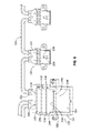
- Figure 1 is a block diagram of a solid state lighting system for a lighting fixture according to an embodiment of the invention.
- Figure 2 illustrates expansion modules for use with the solid state lighting system shown in Figure 1 .
- Figure 3 is a top perspective view of an electronic driver for use in the solid state lighting system shown in Figure 1 .
- Figure 4 is a top perspective view of the electronic driver shown in Figure 3 with an expansion module being mated with the electronic driver.
- Figure 5 is a bottom view of the expansion module shown in Figure 4 .
- Figure 6 is a top perspective view of an alternative electronic driver and expansion modules for the solid state lighting system shown in Figure 1 .
- Figure 7 is a top perspective view of another alternative electronic driver and expansion modules for the solid state lighting system shown in Figure 1 .
- Figure 8 is a top perspective view of yet another alternative electronic driver and expansion modules for the solid state lighting system shown in Figure 1 .
- Figure 9 is a top perspective view of a socket for the electronic driver or the expansion modules shown in Figure 8 .
- Figure 10 is a top perspective view of another alternative electronic driver and expansion modules for the solid state lighting system shown in Figure 1 .
- FIG. 1 is a block diagram of a solid state lighting system 10 for a lighting fixture 12.
- the lighting fixture 12 generally includes a base 14 that supports the various components of the system 10.
- the base 14 may include or may constitute a heat sink 16 for dissipating heat generated by the components of the system 10.
- the system 10 produces light 18 for the lighting fixture 12.
- the lighting fixture 12 is a light engine, for example for residential, commercial or industrial use.
- the lighting fixture 12 may be used for general purpose lighting, or alternatively, may have a customized application or end use.
- the system 10 includes an electronic driver 20 that receives power from a power source 22, a light emitting diode (LED) subassembly 24 that receives power from the electronic driver 20, and one or more expansion modules 26 that control the electronic driver 20, as described in further detail below.
- the electronic driver 20 receives a line voltage from the power source 22, indicated by the power input 28.
- the line voltage may be AC or DC power.
- the power source 22 may be an electrical outlet, a junction box, a battery, a photovoltaic source, and the like.
- the electronic driver 20 takes the power from the power source 22, such as 85-277VAC and outputs a power output 30 to the LED subassembly 24.
- the electronic driver 20 outputs a constant current to the LED subassembly 24, for example 350 mA of constant current.
- the electronic driver 20 controls the power supply to the power output 30 according to a control protocol.
- the electronic driver 20 includes a driver power circuit 32 including the power input 28 and the power output 30.
- the power input 28, and thus the driver power circuit 32 receives power from a power supply circuit 34 that connects the power source 22 with the system 10.
- the electronic driver 20 includes a housing 36 that holds a driver PCB 38.
- the driver power circuit 32 is a circuit formed by the driver PCB 38.
- the driver PCB 38 may have other circuits also.
- the control protocol uses the driver power circuit 32 to convert the power input 28 to the power output 30, such as to a constant current.
- the control protocol uses components of the system 10 to filter the power, for example, filtering noise from the input line, filtering for power factor correction, filtering for rectification, such as between AC and DC power, and the like.
- filtering may be performed to meet certain standards such as energy star standards, FCC interference standards, and the like.
- the filtering may prevent the driver circuit from feeding back undesired effects to the power supply line.
- the control protocol uses components of the system 10 to protect the driver power circuit 32, other components of the electrical driver 20, the LED subassembly 24, the expansion module(s) 26 and/or the power supply circuit 34.
- the control protocol uses components of the system 10 to provide enhanced controls.
- the control protocol may be controlled wirelessly, according to a building control program, according to programmable set points, using daylight harvesting, using dim control, using occupancy control, using emergency light control, using battery back up, and the like.
- Such enhanced controls may be part of the expansion module(s) 26 rather than controls that are built into the electronic driver 20.
- the electronic driver 20 may include components that allow for operation in the basic mode, only.
- the enhanced mode(s) are controlled based on the presence of particular expansion modules 26 having features and components that allow such functionality.
- the electronic driver 20 may be configurable or expandable by simply adding or changing the expansion modules 26 operatively coupled to the electronic driver 20. Any number of expansion modules 26 may be added to the electronic driver 20 as add-ons to change the functionality and control protocol depending on the particular application and desired functionality.
- the expansion modules 26 may include features and components that control one or more functions.
- the expansion modules 26 are selectively useable with the electronic driver 20 and may be easily and readily mated and unmated or swapped in or out to change the control protocol.
- the expansion modules 26 may allow functionality for the filtering mode and/or the circuit protection mode.
- the expansion modules 26 may include features and components that provide the filtering or the circuit protection.
- the electronic driver 20 may have the functionality of the filtering mode and/or the circuit protection mode built in using certain components tied into the driver power circuit 32 or other circuits integral to the electronic driver 20. In such case, the filtering and circuit protection features and components are considered integral to the electronic driver 20 and are not swappable or removable.
- Figure 1 illustrates the electronic driver 20 to have a first expansion port 40 and a second expansion port 42.
- the expansion ports 40, 42 are configured to removably interface with expansion modules 26 to electrically connect the expansion modules 26 to the electronic driver 20.
- the expansion ports 40, 42 may include separable interfaces 44 that non-permanently mate with a corresponding mating interface 46 of one of the expansion modules 26.
- the expansion ports 40, 42 are illustrated as being integral with or as part of the driver PCB 38, however, it is realized that the expansion ports 40, 42 may be part of the driver housing 36.
- the expansion ports 40, 42 may include connectors or receptacles in the housing 36 that interface with the driver PCB 38 or that allow the expansion modules 26 to interface with the driver PCB 38 therethrough.
- the expansion ports 40, 42 may receive multiple different types of expansion modules 26.
- the mating interfaces 46 of each of the different kinds (e.g. each kind having different functionality) of expansion modules 26 may be similar or the same such that any expansion module 26 may mate with any expansion port 40, 42.
- the electronic driver 20 may have any practical number of expansion ports to accommodate different configurations of expansion modules 26.
- any of the expansion ports 46 may be kept open (e.g. no expansion module 26 mated thereto), which would have no affect on the control protocol. As such, if all of the expansion ports 46 were kept open, then the electronic driver 20 would operate in the basic mode (or the filter mode or circuit protection mode if either of those corresponding components were integral to the electronic driver 20).
- the electronic driver 20 is mounted to the base 14 and/or heat sink 16, in a semi-permanent or a permanent manner, such as using fasteners, adhesives, epoxy, and the like.
- the expansion modules 26 may be coupled to, and then removed, repaired and/or replaced separate from the electronic driver 20.
- the expansion modules 26 may be removed and/or mated without removing the electronic driver 20 from the base 14 and/or heat sink 16.
- the electronic driver 20 may be modified, changed, upgraded and/or downgraded in situ quickly and efficiently.
- the system 10 includes a first expansion module 50 and a second expansion module 52.
- the first expansion module 50 has a first functionality that is configured to affect the control protocol in a first manner (e.g. wireless control), and the second expansion module 52 has a second functionality configured to affect the control protocol in a second manner (e.g. dimmer control).
- the first and second expansion modules 50, 52 are selectively coupled to the first and second expansion ports 40, 42, shown by the arrows representing the expansion modules 50, 52 being mated with the expansion ports 40, 42. When mated, the expansion modules 50, 52 will change the control protocol of the electronic driver 20.
- the first and second expansion modules 50, 52 are swappable such that the first expansion module 50 may be mated with the second expansion port 42 and the second expansion module 52 may be mated with the first expansion port 40.
- the first and second expansion modules 50, 52 are also swappable with other expansion modules (not shown) having different functionality that affect the control protocol in different ways than the first and second expansion modules 50, 52.
- the LED subassembly 24 includes an LED PCB 54 having at least one LED 56 thereon.
- the LED 56 creates the light 18.
- the LED PCB 54 receives power from the power output 30 of the electronic driver 20 to power the LED 56.
- the LED subassembly 24 may include multiple LED PCBs 54 that are ganged or daisy chained together.
- the LED PCBs 54 may be arranged adjacent one another, or alternatively, may be spread apart and electrically interconnected by a wire harness.
- the LED subassembly 24 may be mounted to the base 14.
- the LED subassembly 24 may be mounted remote from the base 14 and electrically connected thereto, such as by a wired connection.
- Figure 2 illustrates example expansion modules 26 for use with the solid state lighting system 10 (shown in Figure 1 ).
- Figure 2 shows different types of expansion modules 26 that have different functionality. It is realized that the expansion modules 26 illustrated in Figure 2 are merely representative of possible expansion modules 26 and other types of expansion modules 26 that have different functionality useful within the system 10 may be used in addition to, or in lieu of, the expansion modules 26 illustrated in Figure 2 .
- the expansion modules 26 are illustrated as being card-type modules that are pluggable into a card slot, however, it is realized that the expansion modules 26 may have any structural form that would allow mating and unmating with corresponding, complementary expansion ports.
- the expansion modules 26 are not intended to be limited to the structure illustrated in Figure 2 .
- expansion modules 26 are illustrated as including multiple pads 60 for interfacing with the electronic driver 20 (shown in Figure 1 ), it is realized that other types of connections may be made to the electronic driver 20, including, but not limited to, pins, electrical connectors, wires, and the like.
- the various expansion modules 26 include a first expansion module 62, representing a wireless control type module; a second expansion module 64, representing a light sensing type module, such as for daylight harvesting or dimming controls; a third expansion module 66, representing an occupancy type module; a fourth expansion module 68, representing an emergency light control type module; a fifth expansion module 70, representing a smart dim control type module; and a sixth expansion module 72, representing a basic remote dimming control type module.
- the first expansion module 62 includes an expansion module PCB 74 held within an expansion module housing 76.
- the PCB 74 may be provided without the expansion module housing 76, such as by directly plugging the PCB 74 into a card slot in the electronic driver 20.
- the PCB 74 includes the pads 60 at an edge thereof.
- a microprocessor 78 is soldered to the PCB 74, which forms part of a control circuit 80 of the expansion module 62.
- the expansion module 62 also includes an antenna 82 forming part of the control circuit 80. The antenna 82 allows the expansion module 62 to send and/or receive signals wirelessly, such as to control the on/off or dimming level of the system 10.
- the control circuit 80 is electrically connected to, and thus communicates with, the electronic driver 20 via the pads 60 when the expansion module 62 is mated therewith.
- the electronic driver 20 may thus be controlled by the removable expansion module 62, by changing the control protocol based on a status of the control circuit 80.
- the other expansion modules 64-72 illustrated in Figure 2 include similar features as the expansion module 62 of a PCB, an expansion module housing, pads, a microprocessor, and a control circuit.
- the other expansion modules 64-72 include other components that relate to the specific functionality of the particular expansion module 64-72.
- the expansion module 64 includes a connector 84 that mates with a plug 86 attached to a remote light sensor 88.
- the remote light sensor 88 senses an amount of light, such as sunlight or light from other sources, in the vicinity of the system 10.
- the control circuit may indicate to the electronic driver 20 to dim the lights or shut the lights off.
- the remote light sensor 88 represents an external device coupled to the expansion module 64 by the plug 86.
- the expansion module 66 also includes connectors for plugs connected to a remote occupancy sensor 90 and a dimmer switch 92.
- the remote occupancy sensor 90 detects the presence of a particular object or person in the vicinity of the system 10, such as in the same room as the system 10, and the control circuit may indicate to the electronic driver 20 to turn on the lights or brighten the lights when the presence is detected.
- the control circuit may indicate to the electronic driver 20 the lighting level required.
- the dimmer switch 92 may be remote from the expansion module 66, such as on a wall in the room, and may include a dial or a slider to control the light level.
- the remote occupancy sensor 90 and a dimmer switch 92 both represent external devices coupled to the expansion module 66 by plugs.
- the expansion module 68 includes connectors for plugs connected to a sensor 94 connected to a line circuit breaker configured to sense power loss to the system 10 and connected to a battery 96 or other backup power supply.
- the battery 96 may supply power to the system 10, either through the expansion module 68 or through a direct connection between the battery 96 and the electronic driver 20. If power is to be sent through the expansion module 68, at least some of the pads 60 would be used to connect the battery DC output to a DC rail or other power circuit of the electronic drivers 20.
- the sensor 94 and battery 96 both represent external devices coupled to the expansion module 68 by plugs.
- the expansion module 70 is used to sense chopped AC input from a standard Triac wall dimmer. For example, some of the pads 60 would connect to the line or other power circuit of the electronic driver 20 so the microprocessor can analyze the input in the power circuit.
- the expansion module 72 does not include a microprocessor. Rather, a remote dimmer 98 is connected to the control circuit of the expansion module 72. The control circuit then controls the electronic driver 20 to provide the appropriate level of lighting. Others of the expansion modules 62-70 may be used without a microprocessor.
- the remote dimmer 98 represents an external device coupled to the expansion module 72 by a plug.
- FIG 3 is a top perspective view of an electronic driver 120 for use in the solid state lighting system 10 (shown in Figure 1 ).
- the electronic driver 120 includes a housing 122 holding a driver PCB 124 (shown in Figure 4 ).
- the electronic driver 120 has a line in at a power input 126 from the power source 22.
- the power input 126 is represented by a connector that is configured to mate with a plug at an end of a wire from the power source 22.
- the power input 126 is terminated to, or otherwise electrically connected to the driver PCB 124 to supply the power to the driver PCB 124.
- a similar type of connector may be provided at an opposite end of the housing 122 for a line out at the power output 30 to supply the power to the LED subassembly 24.
- the housing 122 is generally box shaped, however the housing 122 may have any other shape in alternative embodiments, depending on the particular application.
- the housing 122 includes a top 128 and a bottom 130. The bottom 130 rests upon the base 14 and/or heatsink 16 (both shown in Figure 1 ).
- the housing 122 includes a first expansion port 132 and a second expansion port 134. Any number of expansion ports may be provided in alternative embodiments.
- the expansion ports 132, 134 are represented by openings or slots in the top 128 of the housing 122 that provide access to the driver PCB 124. When the expansion ports 132, 134 are not in use (e.g.
- caps 136, 138 are coupled to the expansion ports 132, 134 to cover the openings.
- the caps 136, 138 include latches 140 to secure the caps 136, 138 to the housing 122.
- the caps 136, 138 are removable by deflecting the latches 140 and pulling the caps 136, 138 out of the openings.
- the caps 136, 138 may be tethered to the housing 122 such that, even when the caps 136, 138 are taken out of the expansion ports 132, 134, the caps 136, 138 remain attached to the housing 122.
- FIG 4 is a top perspective view of the electronic driver 120 with an expansion module 150 being mated with the electronic driver 120.
- the cap 136 has been removed from the expansion port 132, thus exposing the driver PCB 124.
- the driver PCB 124 includes pads 152 aligned with the opening in the top 128 and forming part of the expansion port 132.
- a connector (not shown) may be terminated to the driver PCB 124 in alignment with the opening in the top 128 for mating with the expansion module 150.
- the expansion module 150 includes an expansion module housing 154 in the form of a dielectric body, that encases an expansion module PCB 156 (shown in phantom).
- the expansion module PCB 156 includes electronic components (e.g. a microprocessor, capacitors, resistors, transistors, integrated circuit, and the like) that create an electronic circuit or control circuit with a particular control function (e.g. wireless control, filtering, light control, and the like).
- the expansion module 150 may be any one of the expansion modules 62-72 (shown in Figure 2 ) having such functionality described above, or the expansion module 150 may be of a different type having desired functionality for the system 10.
- the electronic driver 120 recognizes the expansion module 150 and the control protocol of the electronic driver 120 is changed based on the functionality of the expansion module 150.
- the expansion module housing 154 is sized and shaped to fit into the expansion port 132.
- the expansion module housing 154 is loaded into the opening in the top 128 such that a mating interface 158 of the expansion module 150 interfaces with the driver PCB 124 (or connector terminated to the driver PCB 124 in such embodiments).
- the expansion module housing 154 includes latches 160 that secure the expansion module 150 within the expansion port 132.
- Other types of securing features other than latches may be used in alternative embodiments, such as flanges, fasteners, and the like.
- the expansion module housing 154 includes guide pegs 162 that are received in corresponding holes 164 in the driver PCB 124.
- the guide pegs 162 orient the expansion module 150 with respect to the expansion port 132 and the pads 152 on the driver PCB 124.
- the expansion module housing 154 also includes a handle 166 that may be gripped by the installer to remove the expansion module 150 from the expansion port 132, such as to replace the expansion module 150 to change the functionality of the electronic driver 120.
- FIG 5 is a bottom view of the expansion module 150.
- the expansion module 150 includes mating contacts 168 in the form of compliant beams at the mating interface 158.
- the mating contacts 168 are configured to mate with corresponding pads 152 (shown in Figure 4 ) on the driver PCB 124 (shown in Figure 4 ).
- the mating contacts 168 are electrically connected to the expansion module PCB 156 (shown in phantom).
- the mating contacts 168 form a separable interface at the mating interface 158, such that the expansion module 150 may repeatedly be mated and unmated from the pads 152.
- the mating contacts 168 are configured to be connected to the pads 152 in a solderless connection.
- the expansion module 150 includes two guide pegs 162 at the mating interface 158.
- the two guide pegs 162 may be sized differently (e.g. have different diameters) to operate as polarizing or keying features.
- the driver PCB 124 may have one hole 164 that is sized too small to receive the larger of the two guide pegs 162.
- the expansion module 150 can only be oriented in one way within the expansion port 132.
- FIG 6 is a top perspective view of an alternative electronic driver 220 and expansion modules 250 for the solid state lighting system 10 (shown in Figure 1 ).
- the electronic driver 220 includes a housing 222 holding a driver PCB 224.
- the electronic driver 220 has a line in at a power input 226 from the power source 22.
- the power input 226 is represented by a socket that receives a plug from the line in from the power source 22.
- the plug from the line in may include contacts that engage the driver PCB 224 directly.
- the plug from the line in may terminate to contacts held by the power input 226, which are then in turn connected to the driver PCB 224.
- a similar type of socket is provided on the housing 222 to define a power output 228 to supply the power to an LED subassembly 230.
- a plug 232 is received in the power output 228, which is connected to wires that supply power to the LED subassembly 230.
- the LED subassembly 230 includes one or more LED sockets 234 that hold individual LED PCBs 236. Each LED PCB includes one or more LEDs 238.
- the LED sockets 234 are daisy chained together by wired connectors 240. Any number of the LED sockets 234 may be connected in series.
- the wired connectors 240 allow the LED sockets 234 to be placed at any position relative to one another in 3D space.
- the LED sockets 234 are not limited to being positioned in a linear, planar arrangement end-to-end. Rather, the wired connectors 240 may have wires of any length to allow any spacing between the LED sockets 234.
- the LED sockets 234 may be placed in a linear configuration, a circular configuration, a grid configuration, a stepped configuration in multiple planes, just to name a few.
- the housing 222 represents a socket that receives the driver PCB 224.
- the housing 222 includes opposed walls 242 that include a plurality of guide slots 244.
- the expansion modules 250 are configured to be loaded into the guide slots 244 to mate with the driver PCB 224.
- the driver PCB 224 includes a plurality of connectors 246 mounted to a top surface 248 of the driver PCB 224.
- the connectors 246 represent card edge connectors that receive the expansion modules 250.
- the guide slots 244 and the connectors 246 cooperate to define expansion ports 252 for the electronic driver 220.
- the expansion modules 250 are received in the expansion ports 252, and may be removed and/or replaced by other expansion modules 250 having the same or different functionality to change the control protocol of the electronic driver 220.
- the expansion modules 250 are arranged in parallel both mechanically and electrically, however other configurations are possible.
- the electronic driver 220 may include a cover (not shown) that may be coupled to the housing 222 to cover the driver PCB 224.
- the cover may include openings or slots that are aligned with the connectors 246, which together with the connectors 246 and guide slots 244 define the expansion ports 252.
- Each expansion module 250 includes an expansion module PCB 254.
- the expansion module PCB 254 includes electronic components (not shown) that create an electronic circuit or control circuit with a particular control function. When the expansion module 250 is mated with the expansion port 252, the electronic driver 220 recognizes the expansion module 250 and the control protocol of the electronic driver 220 is changed based on the functionality of the expansion module 250.
- the expansion module 250 may include an expansion module housing, such as a frame surrounding at least a portion of the expansion module PCB 254.
- the expansion module housing may provide support for the expansion module PCB 254 and/or may provide a gripping surface for removing the expansion module 250 from the expansion port 252.
- the expansion module PCB 254 includes a mating interface 256 that mates with the connector 246. In the illustrated embodiment, the mating interface 256 is represented by a card edge of the expansion module PCB 254 that is received in the card edge slot of the connector 246.
- FIG 7 is a top perspective view of another alternative electronic driver 320 and expansion modules 350 for the solid state lighting system 10 (shown in Figure 1 ).
- the electronic driver 320 and expansion modules 350 are similar to the electronic driver 320 and expansion modules 350 illustrated in Figure 6 , however the electronic driver 320 includes an external control module 352 that is separate from the electronic driver 322.
- the electronic driver 320 includes a housing 322 and a driver PCB 324.
- the driver PCB 324 includes a connector 326 mounted thereto.
- the external control module 352 includes a plug 328 that is mated with the connector 326.
- the plug 328 is provided at an end of wires 330 routed from the external control module 352.
- the external control module 352 is positioned separate from the housing 322 of the electronic driver 322.
- the external control module 352 is not physically connected to or supported by the housing 322.
- the external control module 352 must be separately mounted to the base 14 and/or heat sink 16 (both shown in Figure 1 ), or separately mounted to another structure remote from the base 14 far away from the electronic driver 320.
- FIG 8 is a top perspective view of yet another alternative electronic driver 420 and expansion modules 450 for the solid state lighting system 10 (shown in Figure 1 ).
- the electronic driver 420 includes a housing 422 in the form of a socket that receives a driver PCB 424.
- the housing 422 includes a power input 426 that receives power through the expansion modules 450, as will be described in further detail below.
- the housing 422 includes a power output 428 that supplies power to a LED subassembly (not shown).
- the housing 422 includes an expansion port 430 in the form of a connector at an exterior edge of the housing 422.
- the expansion port 430 has a separable interface 432 for mating with the expansion module(s) 450.
- the expansion port 430 also defines the power input 426, wherein the power from the power supply is feed to the electronic driver 420 through the expansion port 430.
- the expansion modules 450 are connected to the electronic driver 420 through the expansion port 430.
- the expansion modules 450 are ganged together with the electronic driver 420 and arranged in series upstream of the electronic driver 420.
- a first expansion module 452 is arranged at an end of the assembly with a second expansion module 454 positioned between the first expansion module 452 and the electronic driver 420.
- a power connector 456 from the power source is configured to be coupled to an end of the first expansion module 452 opposite the second expansion module 454. Power is routed from the power connector 456 through the first expansion module 452, then through the second expansion module 454, and finally to the electronic driver 420.
- Any number of expansion modules 450 may be arranged upstream of the electronic driver 420.
- the expansion modules 450 each have certain functionality, such as filtering, circuit protection, power control, and the like.
- the types of expansion modules 450 utilized upstream of the electronic driver 420 affect the control protocol of the electronic driver 420.
- the control protocol may be affected by providing the filtering upstream of the electronic driver 420 or by adding certain functionality such as remote control, dimming, light sensing, and the like upstream of the electronic driver 420.
- Each expansion module 450 includes an expansion module housing 460 in the form of a socket that receives an expansion module PCB 462.
- the expansion module PCB 462 includes electronic components (not shown) that create an electronic circuit or control circuit with a particular control function.
- the electronic driver 420 recognizes the expansion module 450 and the control protocol of the electronic driver 420 is changed based on the functionality of the expansion module 450.
- the expansion module PCB 462 may be held in the expansion module housing 460 by latches 464.
- Figure 9 is a top perspective view of an expansion module housing 460 for the expansion module 450.
- the housing 422 of the electronic driver 420 (both shown in Figure 8 ) may be similar to the expansion module housing 460.
- the expansion module housing 460 includes a receptacle 470 that is configured to receive the expansion module PCB 462 (shown in Figure 8 ).
- the expansion module housing 460 includes a first mating end 472 and an opposite second mating end 474.
- the mating ends are hermaphroditic.
- the mating ends 472, 474 have separable mating interfaces 476, 478, respectively.
- the mating interfaces 476, 478 may be substantially identical to one another such that the first mating interface 476 is configured to mate with either the first or second mating interface 476, 478 of an adjacent expansion module 450.
- the mating interface is configured to mate with the separable interface 432 of the expansion port 430 (both shown in Figure 8 ) of the electronic driver 420.
- the mating ends 472, 474 include hooks 480 on one side thereof and pockets 482 on the other side thereof. The hooks 480 are configured to be received in the pockets 482 of an adjacent expansion module 450.
- the expansion module housing 460 includes a plurality of contacts 484 at each of the mating interfaces 476, 478 exposed on the exterior edges of the expansion module housing 460.
- the contacts 484 extend into the receptacle 470 for mating with the expansion module PCB 462.
- the expansion module PCB 462 may include pads (not shown) on the bottom side thereof that engages the contacts 484 when loaded into the receptacle 470.
- the contacts 484 may be compliant beams that deflect when engaging corresponding contacts of an adjacent expansion module, or corresponding contacts in the expansion port 430. The compliant beams may also deflect when mated with the expansion module PCB 462.
- the expansion module 450 includes a heat slug 486 held by the expansion module housing 460. The heat slug 486 is exposed within the receptacle 470 and is configured to thermally engage the expansion module PCB 462 when the expansion module PCB 462 is loaded into the receptacle 470.
- the expansion module housing 460 may include fasteners 488 to secure the expansion module housing 460, such as to the base 14 and/or heat sink 16 (both shown in Figure 1 ). Once secured, the expansion module PCB 462 may be removed from the receptacle 470 and replaced with a different expansion module PCB having different functionality, such as to change the control protocol of the electronic driver 420.
- the LED subassembly may utilize LED housings similar to the expansion module housings 460 illustrated in Figure 9 .
- LED PCBs (not shown) may be loaded into the LED housings in a similar manner as the expansion module PCB 462.
- the LED housings may be connected to the power output 428 (shown in Figure 8 ), which includes an interface similar to the mating interfaces 476, 478.
- FIG 10 is a top perspective view of another alternative electronic driver 520 and expansion modules 550 for the solid state lighting system 10 (shown in Figure 1 ).
- the electronic driver 520 includes a housing 522 in the form of a socket that receives a driver PCB 524.
- the housing 522 includes a power input 526 that receives power through the expansion modules 550, as will be described in further detail below.
- the housing 522 includes a power output 528 that supplies power to a LED subassembly 530.
- the housing 522 includes an expansion port 532 in the form of a socket at an exterior edge of the housing 522.
- the expansion port 532 has a separable interface 534 configured to receive a wired connector 536 from the expansion module(s) 550.
- the expansion port 532 also defines the power input 526, wherein the power from the power supply is feed to the electronic driver 520 through the expansion port 532.
- the expansion modules 550 are connected to the electronic driver 520 through the expansion port 532.
- the expansion modules 550 are daisy chained together with the electronic driver 520 and arranged in series upstream of the electronic driver 520.
- a first expansion module 552 is arranged at an end of the assembly with a second expansion module 554 positioned between the first expansion module 552 and the electronic driver 520.
- a power connector 556 from the power source is configured to be coupled to a receptacle 558 of the first expansion module 552.
- Power is routed from the power connector 556 through the first expansion module 552 to a wired connector 560.
- the wired connector 560 interconnects the first and second expansion modules 552, 554.
- the power is routed through the second expansion module 554 to the wired connector 536 that is connected to the electronic driver 520.
- Any number of expansion modules 550 may be arranged upstream of the electronic driver 520, each being interconnected by wired connectors.
- the expansion modules 550 each have certain functionality, such as filtering, power control, and the like.
- the types of expansion modules 550 utilized upstream of the electronic driver 520 affect the control protocol of the electronic driver 520.
- Each expansion module 550 includes an expansion module housing 562 in the form of a socket that receives an expansion module PCB 564.
- the expansion module PCB 564 includes electronic components (not shown) that create an electronic circuit or control circuit with a particular control function.
- the electronic driver 520 recognizes the expansion module 550 and the control protocol of the electronic driver 520 is changed based on the functionality of the expansion module 550.
- the expansion module PCB 564 may be held in the expansion module housing 562 by latches 566.
- the wired connectors are terminated to the expansion module PCBs 564, such as to pads 568 at edges of the expansion module PCBs 564.
- a connector may be mounted to the expansion module housing 562 of the expansion module PCB 564 and the wired connectors may be mated with such connectors.
- Each of the expansion module housings 562 are physically connected to the housing 522 of the electronic driver 520. As such, a unitary structure is created between the housing 522 and each of the expansion module housings 562.
- the housing 522 includes ears 570 extending from either side thereof.
- the expansion module housings 562 similarly include ears 572.
- the ears of adjacent components are coupled together. For example, one ear may be a male ear and the other ear on the other side may be a female ear.
- the male ears are plugged into the female ears and secured together using a fastener 574.
- the fastener 574 may also operate to secure the structures to the base 14 and/or the heat sink 16 (both shown in Figure 1 ).
Abstract
Description
- The subject matter herein relates generally to solid state lighting systems, and more particularly, to configurable solid state lighting systems.
- Solid-state light lighting systems use solid state light sources, such as light emitting diodes (LEDs), and are being used to replace other lighting systems that use other types of light sources, such as incandescent or fluorescent lamps. The solid-state light sources offer advantages over the lamps, such as rapid turn-on, rapid cycling (on-off-on) times, long useful life span, low power consumption, narrow emitted light bandwidths that eliminate the need for color filters to provide desired colors, and so on.
- Solid-state lighting systems typically include different components that are assembled together to complete the final system. For example, the system typically consists of a driver, a controller, a light source, and a power supply. It is not uncommon for a customer assembling a lighting system to have to go to many different suppliers for each of the individual components, and then assemble the different components, from different manufacturers together. Purchasing the various components from different sources proves to make integration into a functioning system difficult. This non-integrated approach does not allow the ability to effectively package the final lighting system in a lighting fixture efficiently.
- Another problem with known solid state lighting systems is that the components are typically customized for a particular end use application. For example, to achieve certain functionality, the driver will either be custom manufactured for one particular functionality, such as wireless control, dimming capability, programmable set points, and the like. As such, different drivers must be purchased and/or stored by the customer, and the appropriate driver must be selected depending on the desired end use. Furthermore, if the needs or functionality of the lighting system were to change, then the entire driver would need to be removed and replaced. Alternatively, the driver may be over designed such that the driver has multiple functionality, which may or may not be required for the particular end use application. In such situation, the over design of the driver adds to the overall cost of the driver, and the customer may not have need for certain functionality leading the customer to overpay for functionality of the driver that is not needed or wanted.
- The problem to be solved is a need remains for a lighting system that may be efficiently packaged into a lighting fixture. A need remains for a lighting system that may be efficiently configured for an end use application.
- The solution is provided by a solid state lighting system including an electronic driver having a power input configured to receive power from a power source and the electronic driver having a power output. The electronic driver controls the power supply to the power output according to a control protocol, and the electronic driver has at least one expansion port having a separable interface. The system also includes a light emitting diode (LED) subassembly having an LED board having at least one LED that receives power from the power output of the electronic driver to power the LED. The system further includes a first expansion module configured to be coupled to the at least one expansion port of the electronic driver having a first functionality affecting the control protocol, and a second expansion module configured to be coupled to the at least one expansion port of the electronic driver having a second functionality affecting the control protocol. The first and second expansion modules are selectively coupled to the at least one expansion port to change the control protocol. Optionally, the first and second expansion modules may be swappable such that either the first expansion module or the second expansion module may be coupled to any of the at least one expansion port to change the control protocol.
- Embodiments of the invention will now be described by way of example with reference to the accompanying drawings in which:
-
Figure 1 is a block diagram of a solid state lighting system for a lighting fixture according to an embodiment of the invention. -
Figure 2 illustrates expansion modules for use with the solid state lighting system shown inFigure 1 . -
Figure 3 is a top perspective view of an electronic driver for use in the solid state lighting system shown inFigure 1 . -
Figure 4 is a top perspective view of the electronic driver shown inFigure 3 with an expansion module being mated with the electronic driver. -
Figure 5 is a bottom view of the expansion module shown inFigure 4 . -
Figure 6 is a top perspective view of an alternative electronic driver and expansion modules for the solid state lighting system shown inFigure 1 . -
Figure 7 is a top perspective view of another alternative electronic driver and expansion modules for the solid state lighting system shown inFigure 1 . -
Figure 8 is a top perspective view of yet another alternative electronic driver and expansion modules for the solid state lighting system shown inFigure 1 . -
Figure 9 is a top perspective view of a socket for the electronic driver or the expansion modules shown inFigure 8 . -
Figure 10 is a top perspective view of another alternative electronic driver and expansion modules for the solid state lighting system shown inFigure 1 . -
Figure 1 is a block diagram of a solidstate lighting system 10 for alighting fixture 12. Thelighting fixture 12 generally includes abase 14 that supports the various components of thesystem 10. Thebase 14 may include or may constitute aheat sink 16 for dissipating heat generated by the components of thesystem 10. Thesystem 10 produceslight 18 for thelighting fixture 12. In this embodiment thelighting fixture 12 is a light engine, for example for residential, commercial or industrial use. Thelighting fixture 12 may be used for general purpose lighting, or alternatively, may have a customized application or end use. - The
system 10 includes anelectronic driver 20 that receives power from apower source 22, a light emitting diode (LED)subassembly 24 that receives power from theelectronic driver 20, and one ormore expansion modules 26 that control theelectronic driver 20, as described in further detail below. Theelectronic driver 20 receives a line voltage from thepower source 22, indicated by thepower input 28. The line voltage may be AC or DC power. Thepower source 22 may be an electrical outlet, a junction box, a battery, a photovoltaic source, and the like. Theelectronic driver 20 takes the power from thepower source 22, such as 85-277VAC and outputs apower output 30 to theLED subassembly 24. In this embodiment, theelectronic driver 20 outputs a constant current to theLED subassembly 24, for example 350 mA of constant current. - The
electronic driver 20 controls the power supply to thepower output 30 according to a control protocol. Theelectronic driver 20 includes adriver power circuit 32 including thepower input 28 and thepower output 30. Thepower input 28, and thus thedriver power circuit 32, receives power from apower supply circuit 34 that connects thepower source 22 with thesystem 10. In this embodiment, theelectronic driver 20 includes ahousing 36 that holds a driver PCB 38. Thedriver power circuit 32 is a circuit formed by the driver PCB 38. The driver PCB 38 may have other circuits also. - In a basic mode, the control protocol uses the
driver power circuit 32 to convert thepower input 28 to thepower output 30, such as to a constant current. In a filter mode, the control protocol uses components of thesystem 10 to filter the power, for example, filtering noise from the input line, filtering for power factor correction, filtering for rectification, such as between AC and DC power, and the like. Such filtering may be performed to meet certain standards such as energy star standards, FCC interference standards, and the like. For example, the filtering may prevent the driver circuit from feeding back undesired effects to the power supply line. In a circuit protection mode, the control protocol uses components of thesystem 10 to protect thedriver power circuit 32, other components of theelectrical driver 20, theLED subassembly 24, the expansion module(s) 26 and/or thepower supply circuit 34. In an enhanced control mode, the control protocol uses components of thesystem 10 to provide enhanced controls. For example, the control protocol may be controlled wirelessly, according to a building control program, according to programmable set points, using daylight harvesting, using dim control, using occupancy control, using emergency light control, using battery back up, and the like. Such enhanced controls may be part of the expansion module(s) 26 rather than controls that are built into theelectronic driver 20. - The
electronic driver 20 may include components that allow for operation in the basic mode, only. The enhanced mode(s) are controlled based on the presence ofparticular expansion modules 26 having features and components that allow such functionality. As such, theelectronic driver 20 may be configurable or expandable by simply adding or changing theexpansion modules 26 operatively coupled to theelectronic driver 20. Any number ofexpansion modules 26 may be added to theelectronic driver 20 as add-ons to change the functionality and control protocol depending on the particular application and desired functionality. Theexpansion modules 26 may include features and components that control one or more functions. Theexpansion modules 26 are selectively useable with theelectronic driver 20 and may be easily and readily mated and unmated or swapped in or out to change the control protocol. In addition, theexpansion modules 26 may allow functionality for the filtering mode and/or the circuit protection mode. For example, theexpansion modules 26 may include features and components that provide the filtering or the circuit protection. Alternatively, theelectronic driver 20 may have the functionality of the filtering mode and/or the circuit protection mode built in using certain components tied into thedriver power circuit 32 or other circuits integral to theelectronic driver 20. In such case, the filtering and circuit protection features and components are considered integral to theelectronic driver 20 and are not swappable or removable. -
Figure 1 illustrates theelectronic driver 20 to have afirst expansion port 40 and asecond expansion port 42. Theexpansion ports expansion modules 26 to electrically connect theexpansion modules 26 to theelectronic driver 20. For example, theexpansion ports separable interfaces 44 that non-permanently mate with acorresponding mating interface 46 of one of theexpansion modules 26. Theexpansion ports driver PCB 38, however, it is realized that theexpansion ports driver housing 36. For example, theexpansion ports housing 36 that interface with thedriver PCB 38 or that allow theexpansion modules 26 to interface with thedriver PCB 38 therethrough. - The
expansion ports expansion modules 26. For example, the mating interfaces 46 of each of the different kinds (e.g. each kind having different functionality) ofexpansion modules 26 may be similar or the same such that anyexpansion module 26 may mate with anyexpansion port electronic driver 20 may have any practical number of expansion ports to accommodate different configurations ofexpansion modules 26. Additionally, it is realized that any of theexpansion ports 46 may be kept open (e.g. noexpansion module 26 mated thereto), which would have no affect on the control protocol. As such, if all of theexpansion ports 46 were kept open, then theelectronic driver 20 would operate in the basic mode (or the filter mode or circuit protection mode if either of those corresponding components were integral to the electronic driver 20). - The
electronic driver 20 is mounted to thebase 14 and/orheat sink 16, in a semi-permanent or a permanent manner, such as using fasteners, adhesives, epoxy, and the like. Theexpansion modules 26 may be coupled to, and then removed, repaired and/or replaced separate from theelectronic driver 20. For example, theexpansion modules 26 may be removed and/or mated without removing theelectronic driver 20 from thebase 14 and/orheat sink 16. As such, theelectronic driver 20 may be modified, changed, upgraded and/or downgraded in situ quickly and efficiently. - In the illustrated embodiment, the
system 10 includes afirst expansion module 50 and asecond expansion module 52. Thefirst expansion module 50 has a first functionality that is configured to affect the control protocol in a first manner (e.g. wireless control), and thesecond expansion module 52 has a second functionality configured to affect the control protocol in a second manner (e.g. dimmer control). The first andsecond expansion modules second expansion ports expansion modules expansion ports expansion modules electronic driver 20. The first andsecond expansion modules first expansion module 50 may be mated with thesecond expansion port 42 and thesecond expansion module 52 may be mated with thefirst expansion port 40. The first andsecond expansion modules second expansion modules - The
LED subassembly 24 includes anLED PCB 54 having at least oneLED 56 thereon. TheLED 56 creates the light 18. TheLED PCB 54 receives power from thepower output 30 of theelectronic driver 20 to power theLED 56. Optionally, theLED subassembly 24 may includemultiple LED PCBs 54 that are ganged or daisy chained together. TheLED PCBs 54 may be arranged adjacent one another, or alternatively, may be spread apart and electrically interconnected by a wire harness. Optionally, theLED subassembly 24 may be mounted to thebase 14. Alternatively, theLED subassembly 24 may be mounted remote from thebase 14 and electrically connected thereto, such as by a wired connection. -
Figure 2 illustratesexample expansion modules 26 for use with the solid state lighting system 10 (shown inFigure 1 ).Figure 2 shows different types ofexpansion modules 26 that have different functionality. It is realized that theexpansion modules 26 illustrated inFigure 2 are merely representative ofpossible expansion modules 26 and other types ofexpansion modules 26 that have different functionality useful within thesystem 10 may be used in addition to, or in lieu of, theexpansion modules 26 illustrated inFigure 2 . Furthermore, theexpansion modules 26 are illustrated as being card-type modules that are pluggable into a card slot, however, it is realized that theexpansion modules 26 may have any structural form that would allow mating and unmating with corresponding, complementary expansion ports. Theexpansion modules 26 are not intended to be limited to the structure illustrated inFigure 2 . For example, while theexpansion modules 26 are illustrated as including multiple pads 60 for interfacing with the electronic driver 20 (shown inFigure 1 ), it is realized that other types of connections may be made to theelectronic driver 20, including, but not limited to, pins, electrical connectors, wires, and the like. - In the illustrated embodiment, the
various expansion modules 26 include afirst expansion module 62, representing a wireless control type module; asecond expansion module 64, representing a light sensing type module, such as for daylight harvesting or dimming controls; athird expansion module 66, representing an occupancy type module; afourth expansion module 68, representing an emergency light control type module; afifth expansion module 70, representing a smart dim control type module; and asixth expansion module 72, representing a basic remote dimming control type module. - The
first expansion module 62 includes anexpansion module PCB 74 held within anexpansion module housing 76. ThePCB 74 may be provided without theexpansion module housing 76, such as by directly plugging thePCB 74 into a card slot in theelectronic driver 20. ThePCB 74 includes the pads 60 at an edge thereof. Amicroprocessor 78 is soldered to thePCB 74, which forms part of acontrol circuit 80 of theexpansion module 62. Theexpansion module 62 also includes anantenna 82 forming part of thecontrol circuit 80. Theantenna 82 allows theexpansion module 62 to send and/or receive signals wirelessly, such as to control the on/off or dimming level of thesystem 10. Thecontrol circuit 80 is electrically connected to, and thus communicates with, theelectronic driver 20 via the pads 60 when theexpansion module 62 is mated therewith. Theelectronic driver 20 may thus be controlled by theremovable expansion module 62, by changing the control protocol based on a status of thecontrol circuit 80. - Most of the other expansion modules 64-72 illustrated in
Figure 2 include similar features as theexpansion module 62 of a PCB, an expansion module housing, pads, a microprocessor, and a control circuit. However, rather than theantenna 82, the other expansion modules 64-72 include other components that relate to the specific functionality of the particular expansion module 64-72. For example, theexpansion module 64 includes aconnector 84 that mates with aplug 86 attached to a remote light sensor 88. The remote light sensor 88 senses an amount of light, such as sunlight or light from other sources, in the vicinity of thesystem 10. Based on certain programmable set points, the control circuit may indicate to theelectronic driver 20 to dim the lights or shut the lights off. The remote light sensor 88 represents an external device coupled to theexpansion module 64 by theplug 86. - The
expansion module 66 also includes connectors for plugs connected to a remote occupancy sensor 90 and adimmer switch 92. The remote occupancy sensor 90 detects the presence of a particular object or person in the vicinity of thesystem 10, such as in the same room as thesystem 10, and the control circuit may indicate to theelectronic driver 20 to turn on the lights or brighten the lights when the presence is detected. With thedimmer switch 92, the control circuit may indicate to theelectronic driver 20 the lighting level required. For example, thedimmer switch 92 may be remote from theexpansion module 66, such as on a wall in the room, and may include a dial or a slider to control the light level. The remote occupancy sensor 90 and adimmer switch 92 both represent external devices coupled to theexpansion module 66 by plugs. - The
expansion module 68 includes connectors for plugs connected to asensor 94 connected to a line circuit breaker configured to sense power loss to thesystem 10 and connected to abattery 96 or other backup power supply. When a power loss condition is detected by thesensor 94, thebattery 96 may supply power to thesystem 10, either through theexpansion module 68 or through a direct connection between thebattery 96 and theelectronic driver 20. If power is to be sent through theexpansion module 68, at least some of the pads 60 would be used to connect the battery DC output to a DC rail or other power circuit of theelectronic drivers 20. Thesensor 94 andbattery 96 both represent external devices coupled to theexpansion module 68 by plugs. - The
expansion module 70 is used to sense chopped AC input from a standard Triac wall dimmer. For example, some of the pads 60 would connect to the line or other power circuit of theelectronic driver 20 so the microprocessor can analyze the input in the power circuit. - The
expansion module 72 does not include a microprocessor. Rather, aremote dimmer 98 is connected to the control circuit of theexpansion module 72. The control circuit then controls theelectronic driver 20 to provide the appropriate level of lighting. Others of the expansion modules 62-70 may be used without a microprocessor. Theremote dimmer 98 represents an external device coupled to theexpansion module 72 by a plug. -
Figure 3 is a top perspective view of anelectronic driver 120 for use in the solid state lighting system 10 (shown inFigure 1 ). Theelectronic driver 120 includes ahousing 122 holding a driver PCB 124 (shown inFigure 4 ). Theelectronic driver 120 has a line in at apower input 126 from thepower source 22. In the illustrated embodiment, thepower input 126 is represented by a connector that is configured to mate with a plug at an end of a wire from thepower source 22. Thepower input 126 is terminated to, or otherwise electrically connected to thedriver PCB 124 to supply the power to thedriver PCB 124. Optionally, a similar type of connector (not shown) may be provided at an opposite end of thehousing 122 for a line out at thepower output 30 to supply the power to theLED subassembly 24. - The
housing 122 is generally box shaped, however thehousing 122 may have any other shape in alternative embodiments, depending on the particular application. Thehousing 122 includes a top 128 and a bottom 130. The bottom 130 rests upon thebase 14 and/or heatsink 16 (both shown inFigure 1 ). Thehousing 122 includes afirst expansion port 132 and asecond expansion port 134. Any number of expansion ports may be provided in alternative embodiments. In the illustrated embodiment, theexpansion ports housing 122 that provide access to thedriver PCB 124. When theexpansion ports expansion ports caps latches 140 to secure thecaps housing 122. Thecaps latches 140 and pulling thecaps caps housing 122 such that, even when thecaps expansion ports caps housing 122. -
Figure 4 is a top perspective view of theelectronic driver 120 with anexpansion module 150 being mated with theelectronic driver 120. In the illustrated embodiment, thecap 136 has been removed from theexpansion port 132, thus exposing thedriver PCB 124. Thedriver PCB 124 includespads 152 aligned with the opening in the top 128 and forming part of theexpansion port 132. Alternatively, a connector (not shown) may be terminated to thedriver PCB 124 in alignment with the opening in the top 128 for mating with theexpansion module 150. - The
expansion module 150 includes anexpansion module housing 154 in the form of a dielectric body, that encases an expansion module PCB 156 (shown in phantom). Theexpansion module PCB 156 includes electronic components (e.g. a microprocessor, capacitors, resistors, transistors, integrated circuit, and the like) that create an electronic circuit or control circuit with a particular control function (e.g. wireless control, filtering, light control, and the like). Theexpansion module 150 may be any one of the expansion modules 62-72 (shown inFigure 2 ) having such functionality described above, or theexpansion module 150 may be of a different type having desired functionality for thesystem 10. When theexpansion module 150 is mated with theexpansion port 132, theelectronic driver 120 recognizes theexpansion module 150 and the control protocol of theelectronic driver 120 is changed based on the functionality of theexpansion module 150. - The
expansion module housing 154 is sized and shaped to fit into theexpansion port 132. Theexpansion module housing 154 is loaded into the opening in the top 128 such that amating interface 158 of theexpansion module 150 interfaces with the driver PCB 124 (or connector terminated to thedriver PCB 124 in such embodiments). Theexpansion module housing 154 includeslatches 160 that secure theexpansion module 150 within theexpansion port 132. Other types of securing features other than latches may be used in alternative embodiments, such as flanges, fasteners, and the like. In this embodiment, theexpansion module housing 154 includes guide pegs 162 that are received in correspondingholes 164 in thedriver PCB 124. The guide pegs 162 orient theexpansion module 150 with respect to theexpansion port 132 and thepads 152 on thedriver PCB 124. Theexpansion module housing 154 also includes a handle 166 that may be gripped by the installer to remove theexpansion module 150 from theexpansion port 132, such as to replace theexpansion module 150 to change the functionality of theelectronic driver 120. -
Figure 5 is a bottom view of theexpansion module 150. In this embodiment, theexpansion module 150 includesmating contacts 168 in the form of compliant beams at themating interface 158. Themating contacts 168 are configured to mate with corresponding pads 152 (shown inFigure 4 ) on the driver PCB 124 (shown inFigure 4 ). Themating contacts 168 are electrically connected to the expansion module PCB 156 (shown in phantom). Themating contacts 168 form a separable interface at themating interface 158, such that theexpansion module 150 may repeatedly be mated and unmated from thepads 152. Themating contacts 168 are configured to be connected to thepads 152 in a solderless connection. - The
expansion module 150 includes two guide pegs 162 at themating interface 158. Optionally, the two guide pegs 162 may be sized differently (e.g. have different diameters) to operate as polarizing or keying features. For example, thedriver PCB 124 may have onehole 164 that is sized too small to receive the larger of the two guide pegs 162. As such, theexpansion module 150 can only be oriented in one way within theexpansion port 132. -
Figure 6 is a top perspective view of an alternativeelectronic driver 220 andexpansion modules 250 for the solid state lighting system 10 (shown inFigure 1 ). Theelectronic driver 220 includes ahousing 222 holding adriver PCB 224. Theelectronic driver 220 has a line in at apower input 226 from thepower source 22. Thepower input 226 is represented by a socket that receives a plug from the line in from thepower source 22. Optionally, the plug from the line in may include contacts that engage thedriver PCB 224 directly. Alternatively, the plug from the line in may terminate to contacts held by thepower input 226, which are then in turn connected to thedriver PCB 224. A similar type of socket is provided on thehousing 222 to define apower output 228 to supply the power to anLED subassembly 230. For example, aplug 232 is received in thepower output 228, which is connected to wires that supply power to theLED subassembly 230. - The
LED subassembly 230 includes one ormore LED sockets 234 that holdindividual LED PCBs 236. Each LED PCB includes one ormore LEDs 238. TheLED sockets 234 are daisy chained together bywired connectors 240. Any number of theLED sockets 234 may be connected in series. Thewired connectors 240 allow theLED sockets 234 to be placed at any position relative to one another in 3D space. TheLED sockets 234 are not limited to being positioned in a linear, planar arrangement end-to-end. Rather, thewired connectors 240 may have wires of any length to allow any spacing between theLED sockets 234. TheLED sockets 234 may be placed in a linear configuration, a circular configuration, a grid configuration, a stepped configuration in multiple planes, just to name a few. - The
housing 222 represents a socket that receives thedriver PCB 224. Thehousing 222 includes opposedwalls 242 that include a plurality ofguide slots 244. Theexpansion modules 250 are configured to be loaded into theguide slots 244 to mate with thedriver PCB 224. In this embodiment, thedriver PCB 224 includes a plurality ofconnectors 246 mounted to atop surface 248 of thedriver PCB 224. Theconnectors 246 represent card edge connectors that receive theexpansion modules 250. Theguide slots 244 and theconnectors 246 cooperate to defineexpansion ports 252 for theelectronic driver 220. Theexpansion modules 250 are received in theexpansion ports 252, and may be removed and/or replaced byother expansion modules 250 having the same or different functionality to change the control protocol of theelectronic driver 220. In the illustrated embodiment, theexpansion modules 250 are arranged in parallel both mechanically and electrically, however other configurations are possible. Optionally, theelectronic driver 220 may include a cover (not shown) that may be coupled to thehousing 222 to cover thedriver PCB 224. The cover may include openings or slots that are aligned with theconnectors 246, which together with theconnectors 246 and guideslots 244 define theexpansion ports 252. - Each
expansion module 250 includes anexpansion module PCB 254. Theexpansion module PCB 254 includes electronic components (not shown) that create an electronic circuit or control circuit with a particular control function. When theexpansion module 250 is mated with theexpansion port 252, theelectronic driver 220 recognizes theexpansion module 250 and the control protocol of theelectronic driver 220 is changed based on the functionality of theexpansion module 250. Optionally, theexpansion module 250 may include an expansion module housing, such as a frame surrounding at least a portion of theexpansion module PCB 254. The expansion module housing may provide support for theexpansion module PCB 254 and/or may provide a gripping surface for removing theexpansion module 250 from theexpansion port 252. Theexpansion module PCB 254 includes amating interface 256 that mates with theconnector 246. In the illustrated embodiment, themating interface 256 is represented by a card edge of theexpansion module PCB 254 that is received in the card edge slot of theconnector 246. -
Figure 7 is a top perspective view of another alternativeelectronic driver 320 andexpansion modules 350 for the solid state lighting system 10 (shown inFigure 1 ). Theelectronic driver 320 andexpansion modules 350 are similar to theelectronic driver 320 andexpansion modules 350 illustrated inFigure 6 , however theelectronic driver 320 includes anexternal control module 352 that is separate from theelectronic driver 322. - The
electronic driver 320 includes ahousing 322 and adriver PCB 324. Thedriver PCB 324 includes aconnector 326 mounted thereto. Theexternal control module 352 includes aplug 328 that is mated with theconnector 326. Theplug 328 is provided at an end ofwires 330 routed from theexternal control module 352. Theexternal control module 352 is positioned separate from thehousing 322 of theelectronic driver 322. Theexternal control module 352 is not physically connected to or supported by thehousing 322. Theexternal control module 352 must be separately mounted to thebase 14 and/or heat sink 16 (both shown inFigure 1 ), or separately mounted to another structure remote from the base 14 far away from theelectronic driver 320. -
Figure 8 is a top perspective view of yet another alternativeelectronic driver 420 andexpansion modules 450 for the solid state lighting system 10 (shown inFigure 1 ). Theelectronic driver 420 includes ahousing 422 in the form of a socket that receives adriver PCB 424. Thehousing 422 includes apower input 426 that receives power through theexpansion modules 450, as will be described in further detail below. Thehousing 422 includes apower output 428 that supplies power to a LED subassembly (not shown). - In this embodiment, the
housing 422 includes anexpansion port 430 in the form of a connector at an exterior edge of thehousing 422. Theexpansion port 430 has aseparable interface 432 for mating with the expansion module(s) 450. Theexpansion port 430 also defines thepower input 426, wherein the power from the power supply is feed to theelectronic driver 420 through theexpansion port 430. - The
expansion modules 450 are connected to theelectronic driver 420 through theexpansion port 430. In the illustrated embodiment, theexpansion modules 450 are ganged together with theelectronic driver 420 and arranged in series upstream of theelectronic driver 420. For example, afirst expansion module 452 is arranged at an end of the assembly with asecond expansion module 454 positioned between thefirst expansion module 452 and theelectronic driver 420. Apower connector 456 from the power source is configured to be coupled to an end of thefirst expansion module 452 opposite thesecond expansion module 454. Power is routed from thepower connector 456 through thefirst expansion module 452, then through thesecond expansion module 454, and finally to theelectronic driver 420. Any number ofexpansion modules 450 may be arranged upstream of theelectronic driver 420. Theexpansion modules 450 each have certain functionality, such as filtering, circuit protection, power control, and the like. The types ofexpansion modules 450 utilized upstream of theelectronic driver 420 affect the control protocol of theelectronic driver 420. For example, the control protocol may be affected by providing the filtering upstream of theelectronic driver 420 or by adding certain functionality such as remote control, dimming, light sensing, and the like upstream of theelectronic driver 420. - Each
expansion module 450 includes anexpansion module housing 460 in the form of a socket that receives anexpansion module PCB 462. Theexpansion module PCB 462 includes electronic components (not shown) that create an electronic circuit or control circuit with a particular control function. When theexpansion module 450 is mated with theexpansion port 430, either directly or through anotherexpansion module 450, theelectronic driver 420 recognizes theexpansion module 450 and the control protocol of theelectronic driver 420 is changed based on the functionality of theexpansion module 450. Theexpansion module PCB 462 may be held in theexpansion module housing 460 bylatches 464. -
Figure 9 is a top perspective view of anexpansion module housing 460 for theexpansion module 450. In this embodiment, thehousing 422 of the electronic driver 420 (both shown inFigure 8 ) may be similar to theexpansion module housing 460. Theexpansion module housing 460 includes areceptacle 470 that is configured to receive the expansion module PCB 462 (shown inFigure 8 ). - The
expansion module housing 460 includes afirst mating end 472 and an oppositesecond mating end 474. In this embodiment, the mating ends are hermaphroditic. The mating ends 472, 474 have separable mating interfaces 476, 478, respectively. The mating interfaces 476, 478 may be substantially identical to one another such that thefirst mating interface 476 is configured to mate with either the first orsecond mating interface adjacent expansion module 450. Additionally, the mating interface is configured to mate with theseparable interface 432 of the expansion port 430 (both shown inFigure 8 ) of theelectronic driver 420. The mating ends 472, 474 includehooks 480 on one side thereof and pockets 482 on the other side thereof. Thehooks 480 are configured to be received in thepockets 482 of anadjacent expansion module 450. - The
expansion module housing 460 includes a plurality ofcontacts 484 at each of the mating interfaces 476, 478 exposed on the exterior edges of theexpansion module housing 460. Thecontacts 484 extend into thereceptacle 470 for mating with theexpansion module PCB 462. For example, theexpansion module PCB 462 may include pads (not shown) on the bottom side thereof that engages thecontacts 484 when loaded into thereceptacle 470. Thecontacts 484 may be compliant beams that deflect when engaging corresponding contacts of an adjacent expansion module, or corresponding contacts in theexpansion port 430. The compliant beams may also deflect when mated with theexpansion module PCB 462. In this embodiment, theexpansion module 450 includes aheat slug 486 held by theexpansion module housing 460. Theheat slug 486 is exposed within thereceptacle 470 and is configured to thermally engage theexpansion module PCB 462 when theexpansion module PCB 462 is loaded into thereceptacle 470. - The
expansion module housing 460 may includefasteners 488 to secure theexpansion module housing 460, such as to thebase 14 and/or heat sink 16 (both shown inFigure 1 ). Once secured, theexpansion module PCB 462 may be removed from thereceptacle 470 and replaced with a different expansion module PCB having different functionality, such as to change the control protocol of theelectronic driver 420. - The LED subassembly (not shown) may utilize LED housings similar to the
expansion module housings 460 illustrated inFigure 9 . LED PCBs (not shown) may be loaded into the LED housings in a similar manner as theexpansion module PCB 462. The LED housings may be connected to the power output 428 (shown inFigure 8 ), which includes an interface similar to the mating interfaces 476, 478. -
Figure 10 is a top perspective view of another alternativeelectronic driver 520 andexpansion modules 550 for the solid state lighting system 10 (shown inFigure 1 ). Theelectronic driver 520 includes ahousing 522 in the form of a socket that receives adriver PCB 524. Thehousing 522 includes apower input 526 that receives power through theexpansion modules 550, as will be described in further detail below. Thehousing 522 includes apower output 528 that supplies power to aLED subassembly 530. - In this embodiment, the
housing 522 includes anexpansion port 532 in the form of a socket at an exterior edge of thehousing 522. Theexpansion port 532 has aseparable interface 534 configured to receive awired connector 536 from the expansion module(s) 550. Theexpansion port 532 also defines thepower input 526, wherein the power from the power supply is feed to theelectronic driver 520 through theexpansion port 532. - The
expansion modules 550 are connected to theelectronic driver 520 through theexpansion port 532. In the illustrated embodiment, theexpansion modules 550 are daisy chained together with theelectronic driver 520 and arranged in series upstream of theelectronic driver 520. For example, afirst expansion module 552 is arranged at an end of the assembly with asecond expansion module 554 positioned between thefirst expansion module 552 and theelectronic driver 520. Apower connector 556 from the power source is configured to be coupled to areceptacle 558 of thefirst expansion module 552. Power is routed from thepower connector 556 through thefirst expansion module 552 to awired connector 560. Thewired connector 560 interconnects the first andsecond expansion modules second expansion module 554 to thewired connector 536 that is connected to theelectronic driver 520. Any number ofexpansion modules 550 may be arranged upstream of theelectronic driver 520, each being interconnected by wired connectors. Theexpansion modules 550 each have certain functionality, such as filtering, power control, and the like. The types ofexpansion modules 550 utilized upstream of theelectronic driver 520 affect the control protocol of theelectronic driver 520. - Each
expansion module 550 includes anexpansion module housing 562 in the form of a socket that receives anexpansion module PCB 564. Theexpansion module PCB 564 includes electronic components (not shown) that create an electronic circuit or control circuit with a particular control function. When theexpansion module 550 is mated with theexpansion port 532, theelectronic driver 520 recognizes theexpansion module 550 and the control protocol of theelectronic driver 520 is changed based on the functionality of theexpansion module 550. Theexpansion module PCB 564 may be held in theexpansion module housing 562 bylatches 566. The wired connectors are terminated to theexpansion module PCBs 564, such as topads 568 at edges of theexpansion module PCBs 564. Alternatively, a connector may be mounted to theexpansion module housing 562 of theexpansion module PCB 564 and the wired connectors may be mated with such connectors. - Each of the
expansion module housings 562 are physically connected to thehousing 522 of theelectronic driver 520. As such, a unitary structure is created between thehousing 522 and each of theexpansion module housings 562. In the illustrated embodiment, thehousing 522 includesears 570 extending from either side thereof. Theexpansion module housings 562 similarly includeears 572. The ears of adjacent components are coupled together. For example, one ear may be a male ear and the other ear on the other side may be a female ear. The male ears are plugged into the female ears and secured together using a fastener 574. The fastener 574 may also operate to secure the structures to thebase 14 and/or the heat sink 16 (both shown inFigure 1 ).
Claims (15)
- A solid state lighting system (10) comprising:an electronic driver (20) having a power input (28) configured to receive power from a power source (22) and the electronic driver (20) having a power output (30), the electronic driver (20) controlling the power supply to the power output (30) according to a control protocol, the electronic driver (20) having at least one expansion port (40, 42) having a separable interface (44);a light emitting diode (LED) subassembly (24) comprising an LED board (54) having at least one LED (56), the LED subassembly (24) receiving power from the power output (30) of the electronic driver (20) to power the LED (56);a first expansion module (50) configured to be coupled to the at least one expansion port (40, 42) of the electronic driver (20), the first expansion module (50) having a first functionality affecting the control protocol; anda second expansion module (52) configured to be coupled to the at least one expansion port (40, 42) of the electronic driver (20), the second expansion module (52) having a second functionality affecting the control protocol;wherein the first and second expansion modules (50, 52) are selectively coupled to the at least one expansion port (40, 42) to change the control protocol.
- The system (10) of claim 1, wherein the first and second expansion modules (50, 52) are swappable such that either the first expansion module (50) or the second expansion module (52) are configured to be coupled to any of the at least one expansion port (40, 42) to change the control protocol.
- The system (10) of claim 1 or 2, wherein the at least one expansion port (40, 42) includes a first expansion port (40), the first expansion module (50) being removable from the first expansion port (40) and the second expansion module (52) being configured to be coupled to the first expansion port (40) after the first expansion module (50) is removed therefrom.
- The system (10) of any preceding claim, wherein the first and second expansion modules (50, 52) are matable with the at least one expansion port (40, 42) using a pluggable connection, the first and second expansion modules (50, 52) being configured to be unplugged from the at least one expansion port (40, 42) to be replaced with the other of the first and second expansion modules (50, 52).
- The system (10) of any preceding claim, wherein both the first and second expansion modules (50, 52) are coupled to the at least one expansion port (40, 42) in series with one another.
- The system (10) of any of claims 1 to 4, wherein both the first and second expansion modules (50, 52) are coupled to the at least one expansion port (40, 42) in parallel with one another.
- The system (10) of claim 1, wherein the at least one expansion port (40, 42) includes multiple expansion ports each having a different separable interface (44), the first expansion module (50) being coupled to one of the expansion ports (40), the second expansion module (52) being connected to a different one of the expansion ports (42).
- The system (10) of any preceding claim, wherein the electronic driver (20) includes a socket (222) and a driver printed circuit board (PCB) (224) received in the socket (222), the at least one expansion port (40, 42) being defined on an external surface of the socket (222), the at least one expansion port (40, 42) being electrically connected to the driver PCB (224) across a socket interface between the socket (222) and the driver PCB (224).
- The system (10) of any of claims 1 to 7, wherein the electronic driver (20) includes a socket (222) and a driver printed circuit board (PCB) (224) received in the socket (222), the at least one expansion port (40, 42) being defined by pads on the driver PCB (224), the first expansion module (50) being coupled to the pads on the driver PCB (224) in a solderless connection.
- The system (10) of any preceding claim, wherein the power input (28) is integrated with the at least one expansion port (40, 42), the power from the power supply being transferred to the electronic driver (20) through at least one of the first and second expansion modules (50, 52).
- The system (10) of any preceding claim, wherein the electronic driver (20) includes a housing (222) and a driver printed circuit board (PCB) (224) held by the housing (222), the housing (222) having multiple expansion ports configured to receive expansion modules (50, 52) therein, the first expansion module (50) being received in a first of the expansion ports (40) and the second expansion module (52) being received in a second of the expansion ports (42) such that the control protocol is affected by both the first and second expansion modules (50, 52).
- The system (10) of any of claims 1 to 10, wherein only one of the first and second expansion modules (50, 52) is coupled to the at least one expansion port (40, 42) such that the control protocol is affected by only one of the first and second expansion modules (50, 52).
- The system (10) of any preceding claim, wherein the first expansion module (50) has a first expansion module printed circuit board (PCB) (74) having a first control circuit, the first control circuit defining the first functionality, and wherein the second expansion module (52) has a second expansion module printed circuit board (PCB) having a second control circuit, the second control circuit defining the second functionality, at least one of the control circuits constitutes a filter circuit for filtering a power circuit.
- The system (10) of any preceding claim, wherein the first expansion module (50) has a first expansion module printed circuit board (PCB) (74) having a first control circuit, the first expansion module PCB (74) having a connector coupled to the first control circuit and configured to receive a plug from an external device, the external device sending a signal to the first control circuit to define the first functionality.
- The system (10) of any preceding claim, wherein the first expansion module (50) has a first expansion module housing (76) and a first expansion module printed circuit board (PCB) (74) held by the expansion module housing (76), the expansion module housing (76) engaging and being secured to the electronic driver (20).
Applications Claiming Priority (1)
| Application Number | Priority Date | Filing Date | Title |
|---|---|---|---|
| US12/634,492 US8878454B2 (en) | 2009-12-09 | 2009-12-09 | Solid state lighting system |
Publications (2)
| Publication Number | Publication Date |
|---|---|
| EP2334155A1 true EP2334155A1 (en) | 2011-06-15 |
| EP2334155B1 EP2334155B1 (en) | 2015-09-09 |
Family
ID=43799595
Family Applications (1)
| Application Number | Title | Priority Date | Filing Date |
|---|---|---|---|
| EP10193865.2A Active EP2334155B1 (en) | 2009-12-09 | 2010-12-06 | Solid state lighting system |
Country Status (5)
| Country | Link |
|---|---|
| US (1) | US8878454B2 (en) |
| EP (1) | EP2334155B1 (en) |
| JP (1) | JP5641647B2 (en) |
| KR (1) | KR20110065406A (en) |
| CN (1) | CN102170723B (en) |
Cited By (5)
| Publication number | Priority date | Publication date | Assignee | Title |
|---|---|---|---|---|
| GB2517214A (en) * | 2013-08-16 | 2015-02-18 | Cp Electronics Ltd | Lighting control module |
| EP3076761A4 (en) * | 2013-11-26 | 2017-10-11 | Sichuan Sunfor Light Co., Ltd. | Card type led driver and transportation means with card type driver |
| WO2019183929A1 (en) | 2018-03-30 | 2019-10-03 | Tridonic Gmbh & Co Kg | Power supplier |
| WO2020002068A1 (en) * | 2018-06-29 | 2020-01-02 | Tridonic Gmbh & Co Kg | Operating device with a function expanding module |
| US11606876B2 (en) | 2016-05-19 | 2023-03-14 | Cimcon Lighting, Inc. | Configurable data center platform |
Families Citing this family (21)
| Publication number | Priority date | Publication date | Assignee | Title |
|---|---|---|---|---|
| CH705107A2 (en) * | 2011-06-03 | 2012-12-14 | Huber+Suhner Ag | Modular solar cell. |
| TWI512431B (en) * | 2012-04-20 | 2015-12-11 | Gemtek Technology Co Ltd | Assembly structure of an electronic device |
| TWI464563B (en) * | 2012-04-20 | 2014-12-11 | Gemtek Technology Co Ltd | Assembly structure of an electronic device |
| JP6003264B2 (en) * | 2012-06-12 | 2016-10-05 | 株式会社リコー | Lighting device and position information management system |
| US9380683B2 (en) * | 2013-03-15 | 2016-06-28 | Eugene M. Cummings | Lamp dimmer system |
| US9572217B2 (en) | 2013-12-09 | 2017-02-14 | Crestron Electronics Inc. | Light emitting diode driver and method of controlling thereof having a dimmed input sense circuit |
| US9713209B2 (en) | 2013-12-09 | 2017-07-18 | Crestron Electronics, Inc. | Light emitting diode driver with housing having opening for receiving a plug-in module and method of operating thereof |
| CN103925527A (en) * | 2014-04-28 | 2014-07-16 | 江苏达伦电子股份有限公司 | Screen type modular LED lighting system |
| KR102191568B1 (en) * | 2014-05-26 | 2020-12-15 | 엘지이노텍 주식회사 | Communication apparatus and lighting apparatus comprising the same |
| JP6388229B2 (en) * | 2014-08-26 | 2018-09-12 | パナソニックIpマネジメント株式会社 | Light source unit and lighting apparatus |
| JP6735495B2 (en) * | 2014-08-26 | 2020-08-05 | パナソニックIpマネジメント株式会社 | Power supply and lighting equipment |
| JP6384787B2 (en) * | 2014-08-26 | 2018-09-05 | パナソニックIpマネジメント株式会社 | Power supply device and lighting fixture |
| JP6399444B2 (en) * | 2014-09-01 | 2018-10-03 | パナソニックIpマネジメント株式会社 | Power supply device and lighting device |
| US10045451B1 (en) * | 2014-09-09 | 2018-08-07 | Universal Lighting Technologies | Lighting control system, expansion pack, and method of use |
| CA3024613C (en) | 2016-05-19 | 2021-03-16 | Cimcon Lighting, Inc. | Configurable streetlight sensor platform |
| PL3261411T3 (en) * | 2016-06-21 | 2022-07-04 | Schréder S.A. | Driver system for a light emitting device |
| US10524328B1 (en) | 2018-03-30 | 2019-12-31 | Douglas Lighting Controls | Fixture mount sensor with remote energy usage reporting |
| KR101981256B1 (en) * | 2018-11-02 | 2019-05-22 | (주) 제이와이 | Power control module for lamp in machin vision system |
| DE102020112139A1 (en) * | 2020-05-05 | 2021-11-11 | Ledvance Gmbh | Lighting device with expandable functionality |
| DE102020123333A1 (en) * | 2020-09-07 | 2022-03-10 | Ledvance Gmbh | Driver expansion module for retrofitting a driver |
| DE102020123334A1 (en) * | 2020-09-07 | 2022-03-10 | Ledvance Gmbh | Expansion module for functional expansion of a network structure |
Citations (4)
| Publication number | Priority date | Publication date | Assignee | Title |
|---|---|---|---|---|
| US6548967B1 (en) * | 1997-08-26 | 2003-04-15 | Color Kinetics, Inc. | Universal lighting network methods and systems |
| US20040140776A1 (en) * | 2003-01-20 | 2004-07-22 | Diehl Luftfahrt Elektronik Gmbh | Control device for the actuation of lamps |
| US20060262544A1 (en) * | 2005-05-23 | 2006-11-23 | Color Kinetics Incorporated | Modular led-based lighting fixtures having socket engagement features |
| US20080136334A1 (en) * | 2006-12-12 | 2008-06-12 | Robinson Shane P | System and method for controlling lighting |
Family Cites Families (57)
| Publication number | Priority date | Publication date | Assignee | Title |
|---|---|---|---|---|
| US5038255A (en) | 1989-09-09 | 1991-08-06 | Stanley Electric Co., Ltd. | Vehicle lamp |
| US5283716A (en) | 1992-10-16 | 1994-02-01 | Rosemount Inc. | Electrical component support structure |
| US5404282A (en) | 1993-09-17 | 1995-04-04 | Hewlett-Packard Company | Multiple light emitting diode module |
| US5660461A (en) | 1994-12-08 | 1997-08-26 | Quantum Devices, Inc. | Arrays of optoelectronic devices and method of making same |
| DE19818402A1 (en) | 1998-04-24 | 1999-10-28 | Horn Hannes Schulze | Arrangement for illumination and signaling purposes produces light that is friendly to the eye |
| US6712486B1 (en) | 1999-10-19 | 2004-03-30 | Permlight Products, Inc. | Mounting arrangement for light emitting diodes |
| US7241423B2 (en) * | 2000-02-03 | 2007-07-10 | Cellular Process Chemistry, Inc. | Enhancing fluid flow in a stacked plate microreactor |
| US6318886B1 (en) | 2000-02-11 | 2001-11-20 | Whelen Engineering Company | High flux led assembly |
| DE10014804A1 (en) | 2000-03-24 | 2001-09-27 | Swoboda Gmbh Geb | LED containing illumination module for use in cars, has conductor tracks for convection and radiation of heat generated to LED and carrier of insulating material |
| US6667544B1 (en) | 2000-06-30 | 2003-12-23 | Amkor Technology, Inc. | Stackable package having clips for fastening package and tool for opening clips |
| DE10036602A1 (en) * | 2000-07-27 | 2002-02-14 | Cpc Cellular Process Chemistry | Microreactor for reactions between gases and liquids |
| US20030112627A1 (en) | 2000-09-28 | 2003-06-19 | Deese Raymond E. | Flexible sign illumination apparatus, system and method |
| JP2002110376A (en) * | 2000-10-02 | 2002-04-12 | Matsushita Electric Works Ltd | Illumination appratus |
| JP2002163907A (en) | 2000-11-24 | 2002-06-07 | Moriyama Sangyo Kk | Lighting system and lighting unit |
| JP2002232167A (en) * | 2001-01-31 | 2002-08-16 | Fujitsu Ltd | Transmitter, subrack and connector unit |
| US6541800B2 (en) | 2001-02-22 | 2003-04-01 | Weldon Technologies, Inc. | High power LED |
| FR2823995B1 (en) * | 2001-04-25 | 2008-06-06 | Alfa Laval Vicarb | IMPROVED DEVICE FOR EXCHANGING AND / OR REACTING BETWEEN FLUIDS |
| JP3940596B2 (en) | 2001-05-24 | 2007-07-04 | 松下電器産業株式会社 | Illumination light source |
| US6799864B2 (en) | 2001-05-26 | 2004-10-05 | Gelcore Llc | High power LED power pack for spot module illumination |
| CN1464953A (en) | 2001-08-09 | 2003-12-31 | 松下电器产业株式会社 | Led illuminator and card type led illuminating light source |
| DE10147040A1 (en) | 2001-09-25 | 2003-04-24 | Patent Treuhand Ges Fuer Elektrische Gluehlampen Mbh | Lighting unit with at least one LED as a light source |
| US6932495B2 (en) * | 2001-10-01 | 2005-08-23 | Sloanled, Inc. | Channel letter lighting using light emitting diodes |
| US7032894B2 (en) * | 2001-11-05 | 2006-04-25 | Corning Incorporated | Flow distributor for monolith reactors |
| US20030086845A1 (en) * | 2001-11-05 | 2003-05-08 | Adusei George Y. | Catalytic reactor |
| US7380961B2 (en) | 2002-04-24 | 2008-06-03 | Moriyama Sangyo Kabushiki Kaisha | Light source coupler, illuminant device, patterned conductor, and method for manufacturing light source coupler |
| KR20050044865A (en) | 2002-05-08 | 2005-05-13 | 포세온 테크날러지 인코퍼레이티드 | High efficiency solid-state light source and methods of use and manufacture |
| SE524540C2 (en) * | 2002-11-18 | 2004-08-24 | Alfa Laval Corp Ab | Flow control insert in a reactor chamber and reactor provided with the insert |
| JP4124638B2 (en) | 2002-12-16 | 2008-07-23 | 順一 島田 | LED lighting system |
| JP2004253364A (en) | 2003-01-27 | 2004-09-09 | Matsushita Electric Ind Co Ltd | Lighting system |
| DE10303969B4 (en) | 2003-01-31 | 2008-11-27 | Osram Opto Semiconductors Gmbh | Light-emitting diode arrangement with a light-emitting diode and a plurality of light-emitting diodes |
| JP2004268630A (en) * | 2003-03-05 | 2004-09-30 | Yazaki Corp | Electrical connector and auxiliary equipment module |
| DE10319525B4 (en) | 2003-04-30 | 2006-08-31 | Alcan Technology & Management Ltd. | Band-shaped arrangement with a conductor track structure and with it electrically connected electronic components, in particular light band with lighting elements |
| US6911731B2 (en) | 2003-05-14 | 2005-06-28 | Jiahn-Chang Wu | Solderless connection in LED module |
| US20040264195A1 (en) | 2003-06-25 | 2004-12-30 | Chia-Fu Chang | Led light source having a heat sink |
| US6999318B2 (en) | 2003-07-28 | 2006-02-14 | Honeywell International Inc. | Heatsinking electronic devices |
| JP4423462B2 (en) * | 2003-12-22 | 2010-03-03 | 富士電機システムズ株式会社 | Semiconductor power module |
| US7044620B2 (en) | 2004-04-30 | 2006-05-16 | Guide Corporation | LED assembly with reverse circuit board |
| US7677763B2 (en) | 2004-10-20 | 2010-03-16 | Timothy Chan | Method and system for attachment of light emitting diodes to circuitry for use in lighting |
| TWI277223B (en) | 2004-11-03 | 2007-03-21 | Chen-Lun Hsingchen | A low thermal resistance LED package |
| US7042745B1 (en) * | 2004-11-29 | 2006-05-09 | Cotek Electronic Ind. Co. Ltd. | Insulating arrangement for DC/AC inverter |
| US9070850B2 (en) | 2007-10-31 | 2015-06-30 | Cree, Inc. | Light emitting diode package and method for fabricating same |
| US7470405B2 (en) * | 2005-01-25 | 2008-12-30 | Board Of Supervisors Of Louisiana State University And Agricultural And Mechanical College | Microchannel reactor with active oscillatory forcing |
| CA2542987A1 (en) * | 2005-04-12 | 2006-10-12 | J & J Electronics, Inc. | Networkable controllers for led lighting |
| US20060262533A1 (en) | 2005-05-18 | 2006-11-23 | Para Light Electronics Co., Ltd. | Modular light emitting diode |
| US7348604B2 (en) | 2005-05-20 | 2008-03-25 | Tir Technology Lp | Light-emitting module |
| AU2006249979B2 (en) * | 2005-05-23 | 2011-08-25 | Signify North America Corporation | Modular led lighting apparatus for socket engagement |
| JP4548219B2 (en) | 2005-05-25 | 2010-09-22 | パナソニック電工株式会社 | Socket for electronic parts |
| KR100764391B1 (en) | 2006-04-25 | 2007-10-05 | 삼성전기주식회사 | Light emitting diode module |
| US7549786B2 (en) | 2006-12-01 | 2009-06-23 | Cree, Inc. | LED socket and replaceable LED assemblies |
| US7868562B2 (en) * | 2006-12-11 | 2011-01-11 | Koninklijke Philips Electronics N.V. | Luminaire control system and method |
| US7540761B2 (en) | 2007-05-01 | 2009-06-02 | Tyco Electronics Corporation | LED connector assembly with heat sink |
| US7638814B2 (en) | 2007-06-19 | 2009-12-29 | Philips Lumileds Lighting Company, Llc | Solderless integrated package connector and heat sink for LED |
| US7614771B2 (en) | 2007-07-05 | 2009-11-10 | Tyco Electronics Corporation | Wireless controlled light emitting assembly |
| US7682043B2 (en) | 2007-07-05 | 2010-03-23 | Tyco Electronics Corporation | Wirelessly controlled light emitting display system |
| US7611376B2 (en) | 2007-11-20 | 2009-11-03 | Tyco Electronics Corporation | LED socket |
| US8648774B2 (en) | 2007-12-11 | 2014-02-11 | Advance Display Technologies, Inc. | Large scale LED display |
| US8922458B2 (en) * | 2007-12-11 | 2014-12-30 | ADTI Media, LLC | Data and power distribution system and method for a large scale display |
-
2009
- 2009-12-09 US US12/634,492 patent/US8878454B2/en active Active
-
2010
- 2010-12-06 EP EP10193865.2A patent/EP2334155B1/en active Active
- 2010-12-08 JP JP2010273645A patent/JP5641647B2/en active Active
- 2010-12-08 KR KR1020100124929A patent/KR20110065406A/en not_active Application Discontinuation
- 2010-12-09 CN CN201010625074.6A patent/CN102170723B/en active Active
Patent Citations (4)
| Publication number | Priority date | Publication date | Assignee | Title |
|---|---|---|---|---|
| US6548967B1 (en) * | 1997-08-26 | 2003-04-15 | Color Kinetics, Inc. | Universal lighting network methods and systems |
| US20040140776A1 (en) * | 2003-01-20 | 2004-07-22 | Diehl Luftfahrt Elektronik Gmbh | Control device for the actuation of lamps |
| US20060262544A1 (en) * | 2005-05-23 | 2006-11-23 | Color Kinetics Incorporated | Modular led-based lighting fixtures having socket engagement features |
| US20080136334A1 (en) * | 2006-12-12 | 2008-06-12 | Robinson Shane P | System and method for controlling lighting |
Cited By (8)
| Publication number | Priority date | Publication date | Assignee | Title |
|---|---|---|---|---|
| GB2517214A (en) * | 2013-08-16 | 2015-02-18 | Cp Electronics Ltd | Lighting control module |
| GB2517214B (en) * | 2013-08-16 | 2016-04-20 | Cp Electronics Ltd | Lighting control module |
| EP3076761A4 (en) * | 2013-11-26 | 2017-10-11 | Sichuan Sunfor Light Co., Ltd. | Card type led driver and transportation means with card type driver |
| US11606876B2 (en) | 2016-05-19 | 2023-03-14 | Cimcon Lighting, Inc. | Configurable data center platform |
| WO2019183929A1 (en) | 2018-03-30 | 2019-10-03 | Tridonic Gmbh & Co Kg | Power supplier |
| EP3756247A4 (en) * | 2018-03-30 | 2021-09-08 | Tridonic GmbH & Co. KG | Power supplier |
| WO2020002068A1 (en) * | 2018-06-29 | 2020-01-02 | Tridonic Gmbh & Co Kg | Operating device with a function expanding module |
| AT17870U1 (en) * | 2018-06-29 | 2023-05-15 | Tridonic Gmbh & Co Kg | Control gear with a function expansion module |
Also Published As
| Publication number | Publication date |
|---|---|
| KR20110065406A (en) | 2011-06-15 |
| US8878454B2 (en) | 2014-11-04 |
| CN102170723B (en) | 2016-01-13 |
| EP2334155B1 (en) | 2015-09-09 |
| JP5641647B2 (en) | 2014-12-17 |
| US20110133668A1 (en) | 2011-06-09 |
| JP2011138764A (en) | 2011-07-14 |
| CN102170723A (en) | 2011-08-31 |
Similar Documents
| Publication | Publication Date | Title |
|---|---|---|
| EP2334155B1 (en) | Solid state lighting system | |
| EP2333398B1 (en) | LED socket assembly | |
| CN102162631B (en) | Socket assembly with a thermal management structure | |
| EP2423570B1 (en) | LED light module | |
| US7458705B2 (en) | LED illumination device | |
| CN109644533B (en) | Driver system for a light emitting device | |
| US9615414B2 (en) | Power supply device and illumination device | |
| EP2339230A2 (en) | Solid state lighting assembly | |
| CN209909626U (en) | Linear lighting system | |
| US6342766B1 (en) | Power module for high intensity discharge lamp | |
| US10480726B1 (en) | Modular LED lamp system | |
| KR101016112B1 (en) | Light emitted diode light with connecter for multiple connection | |
| CN113966448A (en) | Lamp assembly for street lamp | |
| CN111465152A (en) | Modular control system with input/output bus board and lamp with same | |
| CN201212661Y (en) | Deconcentrator of constant current LED lamp | |
| CN220417249U (en) | Power supply device with intelligent control assembly and lighting equipment | |
| KR20170013632A (en) | parallel LED light | |
| JP2017208314A (en) | Lighting device and luminaire | |
| KR20160060285A (en) | Multi adaptor capable for dimming for fluorescent apparatus | |
| US20110182078A1 (en) | LED cradle | |
| CN103017046A (en) | Lighting apparatus |
Legal Events
| Date | Code | Title | Description |
|---|---|---|---|
| PUAI | Public reference made under article 153(3) epc to a published international application that has entered the european phase |
Free format text: ORIGINAL CODE: 0009012 |
|
| AK | Designated contracting states |
Kind code of ref document: A1 Designated state(s): AL AT BE BG CH CY CZ DE DK EE ES FI FR GB GR HR HU IE IS IT LI LT LU LV MC MK MT NL NO PL PT RO RS SE SI SK SM TR |
|
| AX | Request for extension of the european patent |
Extension state: BA ME |
|
| 17P | Request for examination filed |
Effective date: 20111129 |
|
| 17Q | First examination report despatched |
Effective date: 20130527 |
|
| GRAP | Despatch of communication of intention to grant a patent |
Free format text: ORIGINAL CODE: EPIDOSNIGR1 |
|
| INTG | Intention to grant announced |
Effective date: 20150511 |
|
| GRAS | Grant fee paid |
Free format text: ORIGINAL CODE: EPIDOSNIGR3 |
|
| GRAA | (expected) grant |
Free format text: ORIGINAL CODE: 0009210 |
|
| AK | Designated contracting states |
Kind code of ref document: B1 Designated state(s): AL AT BE BG CH CY CZ DE DK EE ES FI FR GB GR HR HU IE IS IT LI LT LU LV MC MK MT NL NO PL PT RO RS SE SI SK SM TR |
|
| REG | Reference to a national code |
Ref country code: GB Ref legal event code: FG4D |
|
| REG | Reference to a national code |
Ref country code: AT Ref legal event code: REF Ref document number: 749009 Country of ref document: AT Kind code of ref document: T Effective date: 20150915 Ref country code: CH Ref legal event code: EP |
|
| REG | Reference to a national code |
Ref country code: IE Ref legal event code: FG4D |
|
| REG | Reference to a national code |
Ref country code: DE Ref legal event code: R096 Ref document number: 602010027333 Country of ref document: DE |
|
| REG | Reference to a national code |
Ref country code: FR Ref legal event code: PLFP Year of fee payment: 6 |
|
| PG25 | Lapsed in a contracting state [announced via postgrant information from national office to epo] |
Ref country code: LT Free format text: LAPSE BECAUSE OF FAILURE TO SUBMIT A TRANSLATION OF THE DESCRIPTION OR TO PAY THE FEE WITHIN THE PRESCRIBED TIME-LIMIT Effective date: 20150909 Ref country code: LV Free format text: LAPSE BECAUSE OF FAILURE TO SUBMIT A TRANSLATION OF THE DESCRIPTION OR TO PAY THE FEE WITHIN THE PRESCRIBED TIME-LIMIT Effective date: 20150909 Ref country code: FI Free format text: LAPSE BECAUSE OF FAILURE TO SUBMIT A TRANSLATION OF THE DESCRIPTION OR TO PAY THE FEE WITHIN THE PRESCRIBED TIME-LIMIT Effective date: 20150909 Ref country code: GR Free format text: LAPSE BECAUSE OF FAILURE TO SUBMIT A TRANSLATION OF THE DESCRIPTION OR TO PAY THE FEE WITHIN THE PRESCRIBED TIME-LIMIT Effective date: 20151210 Ref country code: NO Free format text: LAPSE BECAUSE OF FAILURE TO SUBMIT A TRANSLATION OF THE DESCRIPTION OR TO PAY THE FEE WITHIN THE PRESCRIBED TIME-LIMIT Effective date: 20151209 |
|
| REG | Reference to a national code |
Ref country code: LT Ref legal event code: MG4D Ref country code: NL Ref legal event code: FP |
|
| REG | Reference to a national code |
Ref country code: AT Ref legal event code: MK05 Ref document number: 749009 Country of ref document: AT Kind code of ref document: T Effective date: 20150909 |
|
| PG25 | Lapsed in a contracting state [announced via postgrant information from national office to epo] |
Ref country code: ES Free format text: LAPSE BECAUSE OF FAILURE TO SUBMIT A TRANSLATION OF THE DESCRIPTION OR TO PAY THE FEE WITHIN THE PRESCRIBED TIME-LIMIT Effective date: 20150909 Ref country code: RS Free format text: LAPSE BECAUSE OF FAILURE TO SUBMIT A TRANSLATION OF THE DESCRIPTION OR TO PAY THE FEE WITHIN THE PRESCRIBED TIME-LIMIT Effective date: 20150909 Ref country code: HR Free format text: LAPSE BECAUSE OF FAILURE TO SUBMIT A TRANSLATION OF THE DESCRIPTION OR TO PAY THE FEE WITHIN THE PRESCRIBED TIME-LIMIT Effective date: 20150909 Ref country code: SE Free format text: LAPSE BECAUSE OF FAILURE TO SUBMIT A TRANSLATION OF THE DESCRIPTION OR TO PAY THE FEE WITHIN THE PRESCRIBED TIME-LIMIT Effective date: 20150909 |
|
| PG25 | Lapsed in a contracting state [announced via postgrant information from national office to epo] |
Ref country code: SK Free format text: LAPSE BECAUSE OF FAILURE TO SUBMIT A TRANSLATION OF THE DESCRIPTION OR TO PAY THE FEE WITHIN THE PRESCRIBED TIME-LIMIT Effective date: 20150909 Ref country code: CZ Free format text: LAPSE BECAUSE OF FAILURE TO SUBMIT A TRANSLATION OF THE DESCRIPTION OR TO PAY THE FEE WITHIN THE PRESCRIBED TIME-LIMIT Effective date: 20150909 Ref country code: IT Free format text: LAPSE BECAUSE OF FAILURE TO SUBMIT A TRANSLATION OF THE DESCRIPTION OR TO PAY THE FEE WITHIN THE PRESCRIBED TIME-LIMIT Effective date: 20150909 Ref country code: EE Free format text: LAPSE BECAUSE OF FAILURE TO SUBMIT A TRANSLATION OF THE DESCRIPTION OR TO PAY THE FEE WITHIN THE PRESCRIBED TIME-LIMIT Effective date: 20150909 Ref country code: IS Free format text: LAPSE BECAUSE OF FAILURE TO SUBMIT A TRANSLATION OF THE DESCRIPTION OR TO PAY THE FEE WITHIN THE PRESCRIBED TIME-LIMIT Effective date: 20160109 |
|
| PG25 | Lapsed in a contracting state [announced via postgrant information from national office to epo] |
Ref country code: PT Free format text: LAPSE BECAUSE OF FAILURE TO SUBMIT A TRANSLATION OF THE DESCRIPTION OR TO PAY THE FEE WITHIN THE PRESCRIBED TIME-LIMIT Effective date: 20160111 Ref country code: AT Free format text: LAPSE BECAUSE OF FAILURE TO SUBMIT A TRANSLATION OF THE DESCRIPTION OR TO PAY THE FEE WITHIN THE PRESCRIBED TIME-LIMIT Effective date: 20150909 Ref country code: RO Free format text: LAPSE BECAUSE OF FAILURE TO SUBMIT A TRANSLATION OF THE DESCRIPTION OR TO PAY THE FEE WITHIN THE PRESCRIBED TIME-LIMIT Effective date: 20150909 Ref country code: PL Free format text: LAPSE BECAUSE OF FAILURE TO SUBMIT A TRANSLATION OF THE DESCRIPTION OR TO PAY THE FEE WITHIN THE PRESCRIBED TIME-LIMIT Effective date: 20150909 Ref country code: BE Free format text: LAPSE BECAUSE OF NON-PAYMENT OF DUE FEES Effective date: 20151231 |
|
| REG | Reference to a national code |
Ref country code: DE Ref legal event code: R097 Ref document number: 602010027333 Country of ref document: DE |
|
| PLBE | No opposition filed within time limit |
Free format text: ORIGINAL CODE: 0009261 |
|
| STAA | Information on the status of an ep patent application or granted ep patent |
Free format text: STATUS: NO OPPOSITION FILED WITHIN TIME LIMIT |
|
| PG25 | Lapsed in a contracting state [announced via postgrant information from national office to epo] |
Ref country code: MC Free format text: LAPSE BECAUSE OF FAILURE TO SUBMIT A TRANSLATION OF THE DESCRIPTION OR TO PAY THE FEE WITHIN THE PRESCRIBED TIME-LIMIT Effective date: 20150909 Ref country code: LU Free format text: LAPSE BECAUSE OF FAILURE TO SUBMIT A TRANSLATION OF THE DESCRIPTION OR TO PAY THE FEE WITHIN THE PRESCRIBED TIME-LIMIT Effective date: 20151206 |
|
| REG | Reference to a national code |
Ref country code: CH Ref legal event code: PL |
|
| 26N | No opposition filed |
Effective date: 20160610 |
|
| PG25 | Lapsed in a contracting state [announced via postgrant information from national office to epo] |
Ref country code: DK Free format text: LAPSE BECAUSE OF FAILURE TO SUBMIT A TRANSLATION OF THE DESCRIPTION OR TO PAY THE FEE WITHIN THE PRESCRIBED TIME-LIMIT Effective date: 20150909 Ref country code: SI Free format text: LAPSE BECAUSE OF FAILURE TO SUBMIT A TRANSLATION OF THE DESCRIPTION OR TO PAY THE FEE WITHIN THE PRESCRIBED TIME-LIMIT Effective date: 20150909 |
|
| REG | Reference to a national code |
Ref country code: IE Ref legal event code: MM4A |
|
| PG25 | Lapsed in a contracting state [announced via postgrant information from national office to epo] |
Ref country code: CH Free format text: LAPSE BECAUSE OF NON-PAYMENT OF DUE FEES Effective date: 20151231 Ref country code: IE Free format text: LAPSE BECAUSE OF NON-PAYMENT OF DUE FEES Effective date: 20151206 Ref country code: LI Free format text: LAPSE BECAUSE OF NON-PAYMENT OF DUE FEES Effective date: 20151231 |
|
| REG | Reference to a national code |
Ref country code: FR Ref legal event code: PLFP Year of fee payment: 7 |
|
| PG25 | Lapsed in a contracting state [announced via postgrant information from national office to epo] |
Ref country code: BE Free format text: LAPSE BECAUSE OF FAILURE TO SUBMIT A TRANSLATION OF THE DESCRIPTION OR TO PAY THE FEE WITHIN THE PRESCRIBED TIME-LIMIT Effective date: 20150909 |
|
| PG25 | Lapsed in a contracting state [announced via postgrant information from national office to epo] |
Ref country code: BG Free format text: LAPSE BECAUSE OF FAILURE TO SUBMIT A TRANSLATION OF THE DESCRIPTION OR TO PAY THE FEE WITHIN THE PRESCRIBED TIME-LIMIT Effective date: 20150909 Ref country code: SM Free format text: LAPSE BECAUSE OF FAILURE TO SUBMIT A TRANSLATION OF THE DESCRIPTION OR TO PAY THE FEE WITHIN THE PRESCRIBED TIME-LIMIT Effective date: 20150909 Ref country code: HU Free format text: LAPSE BECAUSE OF FAILURE TO SUBMIT A TRANSLATION OF THE DESCRIPTION OR TO PAY THE FEE WITHIN THE PRESCRIBED TIME-LIMIT; INVALID AB INITIO Effective date: 20101206 |
|
| PG25 | Lapsed in a contracting state [announced via postgrant information from national office to epo] |
Ref country code: CY Free format text: LAPSE BECAUSE OF FAILURE TO SUBMIT A TRANSLATION OF THE DESCRIPTION OR TO PAY THE FEE WITHIN THE PRESCRIBED TIME-LIMIT Effective date: 20150909 |
|
| PG25 | Lapsed in a contracting state [announced via postgrant information from national office to epo] |
Ref country code: TR Free format text: LAPSE BECAUSE OF FAILURE TO SUBMIT A TRANSLATION OF THE DESCRIPTION OR TO PAY THE FEE WITHIN THE PRESCRIBED TIME-LIMIT Effective date: 20150909 Ref country code: MT Free format text: LAPSE BECAUSE OF FAILURE TO SUBMIT A TRANSLATION OF THE DESCRIPTION OR TO PAY THE FEE WITHIN THE PRESCRIBED TIME-LIMIT Effective date: 20150909 |
|
| REG | Reference to a national code |
Ref country code: FR Ref legal event code: PLFP Year of fee payment: 8 |
|
| REG | Reference to a national code |
Ref country code: NL Ref legal event code: HC Owner name: TE CONNECTIVITY CORPORATION; US Free format text: DETAILS ASSIGNMENT: CHANGE OF OWNER(S), CHANGE OF OWNER(S) NAME; FORMER OWNER NAME: TYCO ELECTRONICS CORPORATION Effective date: 20180328 |
|
| PG25 | Lapsed in a contracting state [announced via postgrant information from national office to epo] |
Ref country code: MK Free format text: LAPSE BECAUSE OF FAILURE TO SUBMIT A TRANSLATION OF THE DESCRIPTION OR TO PAY THE FEE WITHIN THE PRESCRIBED TIME-LIMIT Effective date: 20150909 |
|
| REG | Reference to a national code |
Ref country code: FR Ref legal event code: CD Owner name: TYCO ELECTRONICS CORPORATION, US Effective date: 20180626 |
|
| REG | Reference to a national code |
Ref country code: DE Ref legal event code: R082 Ref document number: 602010027333 Country of ref document: DE Representative=s name: MARKS & CLERK (LUXEMBOURG) LLP, LU Ref country code: DE Ref legal event code: R081 Ref document number: 602010027333 Country of ref document: DE Owner name: TE CONNECTIVITY CORPORATION, BERWYN, US Free format text: FORMER OWNER: TYCO ELECTRONICS CORPORATION, BERWYN, PA., US |
|
| PG25 | Lapsed in a contracting state [announced via postgrant information from national office to epo] |
Ref country code: AL Free format text: LAPSE BECAUSE OF FAILURE TO SUBMIT A TRANSLATION OF THE DESCRIPTION OR TO PAY THE FEE WITHIN THE PRESCRIBED TIME-LIMIT Effective date: 20150909 |
|
| REG | Reference to a national code |
Ref country code: NL Ref legal event code: PD Owner name: TE CONNECTIVITY SERVICES GMBH; CH Free format text: DETAILS ASSIGNMENT: CHANGE OF OWNER(S), ASSIGNMENT; FORMER OWNER NAME: TE CONNECTIVITY SERVICES GMBH Effective date: 20230912 |
|
| PGFP | Annual fee paid to national office [announced via postgrant information from national office to epo] |
Ref country code: NL Payment date: 20231016 Year of fee payment: 14 Ref country code: FR Payment date: 20230929 Year of fee payment: 14 |
|
| PGFP | Annual fee paid to national office [announced via postgrant information from national office to epo] |
Ref country code: GB Payment date: 20231012 Year of fee payment: 14 |
|
| PGFP | Annual fee paid to national office [announced via postgrant information from national office to epo] |
Ref country code: DE Payment date: 20231010 Year of fee payment: 14 |