EP2328091B1 - Network media playout - Google Patents
Network media playout Download PDFInfo
- Publication number
- EP2328091B1 EP2328091B1 EP11156611.3A EP11156611A EP2328091B1 EP 2328091 B1 EP2328091 B1 EP 2328091B1 EP 11156611 A EP11156611 A EP 11156611A EP 2328091 B1 EP2328091 B1 EP 2328091B1
- Authority
- EP
- European Patent Office
- Prior art keywords
- buffer
- data
- media
- amount
- threshold
- Prior art date
- Legal status (The legal status is an assumption and is not a legal conclusion. Google has not performed a legal analysis and makes no representation as to the accuracy of the status listed.)
- Expired - Lifetime
Links
Images
Classifications
-
- H—ELECTRICITY
- H04—ELECTRIC COMMUNICATION TECHNIQUE
- H04L—TRANSMISSION OF DIGITAL INFORMATION, e.g. TELEGRAPHIC COMMUNICATION
- H04L12/00—Data switching networks
- H04L12/64—Hybrid switching systems
- H04L12/6418—Hybrid transport
-
- H—ELECTRICITY
- H04—ELECTRIC COMMUNICATION TECHNIQUE
- H04L—TRANSMISSION OF DIGITAL INFORMATION, e.g. TELEGRAPHIC COMMUNICATION
- H04L65/00—Network arrangements, protocols or services for supporting real-time applications in data packet communication
- H04L65/60—Network streaming of media packets
- H04L65/75—Media network packet handling
- H04L65/764—Media network packet handling at the destination
-
- H—ELECTRICITY
- H04—ELECTRIC COMMUNICATION TECHNIQUE
- H04L—TRANSMISSION OF DIGITAL INFORMATION, e.g. TELEGRAPHIC COMMUNICATION
- H04L65/00—Network arrangements, protocols or services for supporting real-time applications in data packet communication
- H04L65/80—Responding to QoS
-
- H—ELECTRICITY
- H04—ELECTRIC COMMUNICATION TECHNIQUE
- H04L—TRANSMISSION OF DIGITAL INFORMATION, e.g. TELEGRAPHIC COMMUNICATION
- H04L9/00—Cryptographic mechanisms or cryptographic arrangements for secret or secure communications; Network security protocols
- H04L9/40—Network security protocols
-
- H—ELECTRICITY
- H04—ELECTRIC COMMUNICATION TECHNIQUE
- H04L—TRANSMISSION OF DIGITAL INFORMATION, e.g. TELEGRAPHIC COMMUNICATION
- H04L12/00—Data switching networks
- H04L12/64—Hybrid switching systems
- H04L12/6418—Hybrid transport
- H04L2012/6472—Internet
-
- H—ELECTRICITY
- H04—ELECTRIC COMMUNICATION TECHNIQUE
- H04L—TRANSMISSION OF DIGITAL INFORMATION, e.g. TELEGRAPHIC COMMUNICATION
- H04L12/00—Data switching networks
- H04L12/64—Hybrid switching systems
- H04L12/6418—Hybrid transport
- H04L2012/6481—Speech, voice
-
- H—ELECTRICITY
- H04—ELECTRIC COMMUNICATION TECHNIQUE
- H04L—TRANSMISSION OF DIGITAL INFORMATION, e.g. TELEGRAPHIC COMMUNICATION
- H04L12/00—Data switching networks
- H04L12/64—Hybrid switching systems
- H04L12/6418—Hybrid transport
- H04L2012/6489—Buffer Management, Threshold setting, Scheduling, Shaping
-
- H—ELECTRICITY
- H04—ELECTRIC COMMUNICATION TECHNIQUE
- H04L—TRANSMISSION OF DIGITAL INFORMATION, e.g. TELEGRAPHIC COMMUNICATION
- H04L65/00—Network arrangements, protocols or services for supporting real-time applications in data packet communication
- H04L65/1066—Session management
- H04L65/1101—Session protocols
Abstract
Description
- This application claims the benefit of
US Provisional Application Serial No. 60/327,177, filed on October 3,2001 - This invention relates in general to real-time media playout and, more specifically, to computer media playout of network provided media.
- The receiver part of a packet communication device is characterized by having as input an asynchronous flow of data packets. A real time media playout device needs to produce a continuous output of data, e.g., to a loudspeaker. Furthermore, for a real time application such as telephony, streamed audio, or streamed video it is important that the delay is minimized and therefore the delay in the receiver and the playout device should be as small as possible.
- The real-time media device is defined as the software and/or hardware that convert the digital media signal to a signal suitable for playout, for example an analog signal that can be fed into a speaker. In a computer the real-time media device is usually referred to as a sound card or sound board when the media is sound and a video card or video board when the media is video. The packet communication device is usually referred to as a network adaptor, which in a computer could be a network card or a modem.
- The quality of media playout is a subjective standard and is an important part of achieving high Quality of Service (QOS). The incoming packets from the network are characterized by at least three factors that affect the playout quality and the QOS, namely, latency, clock drift and packet loss. Latency is a measure of how the packets are delayed in the network. This delay can vary from packet to packet. These variations are referred to as jitter. Clock drift is when the incoming packets arrives at a pace that does not represent the pace of the playout by the playout device. Packet loss is when not all of the packets that represent the media stream are received for playout. Real-time media playout with adequate QOS maintains a high perceptual quality to the user. That also includes having low delay, to ensure high quality real time communication.
- A prior art receiver used in a state of the art real time communication system over packet networks consists of: a jitter buffer, a decoder, a packet loss concealment unit, and a real time media playout device. The jitter buffer accumulates packets to mitigate the effects of jitter and reorders the received packets, if necessary, so that the packets can be taken out of the buffer with regular intervals in proper temporal order. The decoder converts the digital information in the packets into a media signal that can be fed to the playout device. The packet loss concealment (PLC) unit produces a media signal when a packet is lost (i.e., the packet is not available in the jitter buffer). For example in sound playout, one simple packet loss concealment technique is to replace the missing packets with zeros. This technique is usually referred to as zero-stuffing. The real time media playout device (e.g., a sound card or other audio device on a computer) typically has a buffer and a digital to analog (D/A) converter.
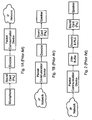
- With reference to
FIG. 1 , a simple transmitter and a simple receiver are respectively shown as Side A and Side B. The simple receiver consists of a packet communication device, a decoder and a real time media device for playout to a loudspeaker. As soon as a packet arrives from the packet network the packet communication device will send it to the decoder that decodes it and sends it to a buffer in the real time media device. The real time media device converts the audio from digital to analog and sends the analog signal to the loudspeaker. This playout design suffers from a loss in perceptual quality because there is no mechanism to mitigate jitter and reordering and there is no packet loss concealment unit. - Also, if the simple receiver does not have the same frequency as the simple transmitter there will be a mismatch sometimes referred to as "clock drift". For example, assume that the simple transmitter uses frequency fsA Hz and the simple receiver uses frequency fsB Hz and that fsB > fsA. This means that the simple transmitter records fsA samples per second and that the simple receiver plays out fsB samples per second. Since fsB > fsA in our example that will cause the buffer in the simple receiver to run out of media to playout presuming the recording is done in real time. This discontinuity will have the same effect as having packet losses where zero-stuffing is used as the concealment method.
- Referring next to
FIG. 2 , a more advanced receiver is shown that consists of a packet communication device, a jitter buffer, a decoder and a real time media device for playout to a loudspeaker. Side A is not shown in relation toFIG. 2 , but is the same as Side A shown inFIG. 1 . As soon as a packet arrives from the Internet protocol (IP) network the packet communication device places it in the jitter buffer that reorders the packet if necessary. A timer decides when to extract a packet from the jitter buffer and decode it. This timer is set to trigger at the same time interval as the packet size. When the packet is decoded it is put in the real time media device's buffer. If no packet is present in the jitter buffer when the timer is triggered then packet loss concealment is performed and the data produced is put in the real time media device's buffer. The real time media device converts the audio signal from being digital to analog and sends the analog signal to the loudspeaker. - This more advanced playout method will correct the problem of reordered packets and may have a more advanced packet loss concealment method than zero-stuffing. But since the timer for the call to the jitter buffer is not synchronized with the clock in the real time media device it will be a mismatch so that it will still suffer from "clock drift". If the timer is "faster" than the clock in the real time media device the buffer in the real time media device is filled faster than it manages to playout and the delay increases over time. If on the other hand, the playout is faster than the timer then the buffer will run out of media to playout, i.e., it will underrun. The underrun will sound like packet loss with zero-stuffing as the packet loss concealment method. This problem is caused by the fact that two clocks are used; one for the interaction with the packet network, jitter buffering and decoding and one for the real time media device.
- One solution for this problem could be to use one clock for all processes, like on a DSP, but this is not practical with PCs where the central processing unit handles the interaction with the packet network, jitter buffering and decoding and the sound card handles D/A-conversion. But this is not the only inaccuracy that will cause "clock drift," as explained in relation to
FIG. 1 above. If for some reason the CPU clock and the sound card clock were to be perfectly synchronized the different sampling rates on side A and side B as can be seen in the example ofFIG. 1 would cause the jitter buffer to either run out of data or get filled up. The first scenario explained in relation toFIG. 1 would happen if fsA > fsB and the second scenario explained in relation toFIG. 2 would happen if fsA < fsB. - An example of prior art may be found in
WO 95/22233 - Other examples of prior art may be found in
US6167032 relating to a system and method to avoid transmit underruns from a host system to a communication network using an adjustable threshold on a frame basis orGB2349296 - The present invention is defined by the appended claims.
- The present invention is described in conjunction with the appended figures:
-
FIG. 1 is a prior art block diagram of a simple transmitter and a simple receiver that respectively record and playout an audio stream; -
FIG. 2 is a prior art block diagram of an advanced receiver; -
FIG. 3 is a block diagram of an embodiment of a content receiver; -
FIG. 4 is a block diagram of an embodiment of a content receiver; -
FIG. 5 is a flow diagram of an embodiment of a process for feeding data into a playout device; and -
FIG. 6 is a flow diagram of an embodiment of a process for receiving data from a packet network and storing that data in a jitter buffer. - In the appended figures, similar components and/or features may have the same reference label.
- The ensuing description provides preferred exemplary embodiment(s) only, and is not intended to limit the scope, applicability or configuration of the invention. Rather, the ensuing description of the preferred exemplary embodiment(s) will provide those skilled in the art with an enabling description for implementing a preferred exemplary embodiment of the invention. It being understood that various changes may be made in the function and arrangement of elements without departing from the spirit and scope of the invention as set forth in the appended claims.
- The present invention provides a system and method for improving playout of media streamed from a packet switched network. The buffer of the media playout device is monitored such that continuous playout of media is largely guaranteed. This is achieved by comparing the amount of media in the buffer with a threshold. Once the amount of data is less than the threshold, data is requested from the jitter buffer. The jitter buffer either has data that it passes to the decoder or a packet loss concealment operation is performed to create data. The data produced is then put in the real time media playout device's buffer. So the status of the buffer is used to trigger loading more media samples into that buffer. The delay associated with the jitter buffering and packet loss correction is kept within a range that provides adequate QOS.
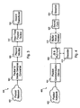
- Referring first to
FIG. 3 , a block diagram of acontent receiver 300 is shown that includes a packet tomedia samples converter 304, aplayout monitor 308 and a real timemedia playout device 312. Compared to the simple and advanced receivers described in the Background Section, theplayout monitor 308 is included. This playout monitor 308 manages the state of a buffer in theplayout device 312 and detects when more data is needed for playout. In contrast, the simple receiver ofFIG. 1 determines the playout rate from incoming packets and the advanced receiver ofFIG. 2 determines the playout rate from a timer. The packet tomedia samples converter 304 provides media samples when requested by theplayout monitor 308, even when the IP packets are delayed or lost. The perceptual quality of the played media samples are affected by the packet stream from thenetwork 402 and by the performance of the packet tomedia samples converter 304. - With reference to
FIG. 4 , a block diagram of an embodiment of acontent receiver 400 is shown that controls the playout of a voice over Internet protocol (VOIP) stream. The method is implemented on a PC running, Microsoft™ Windows as an operating system, for example. Included in thecontent receiver 400 are apacket communication device 404, a combined jitter buffer (JB) and a packet loss concealment (PLC) unit, avoice decoder 412, abuffer status monitor 416, asound card 420, and aloudspeaker 424. The different elements of the content receiver are described below. - The
packet communication device 404 interfaces with theIP network 402 and extracts the media out of the packets that are received from theIP network 402. The JB &PLC unit 408 reduces the distortions of network transmission such as packet loss, jitter and delay to maximize the perceptual quality of the media samples. Important to notice is that this JB &PLC unit 408 tries to keep a minimum of packets in the buffer. The amount of packets in the buffer at any time instant is based on statistics of the incoming packet stream. When the JB &PLC unit 408 is requested to produce data, it determines whether there is data in the buffer or not. If there is data in the buffer, it is decoded when available or a packet loss concealment operation is performed to produce data. Thevoice decoder 412 decompresses the audio stream. - For example, the sound card may record audio samples using 16 bits per sample. Using an audio encoder according to the G.711-standard, this stream is compressed to 8 bits per sample. At the
receiver 400, the 8 bits per sample stream is decompressed by thedecoder 412 and the output is a 16 bit per sample audio stream. Decoding converts the transmitted bit stream to a bit stream that thesound card 420 can understand which could include conversion of formats, bit size of each sample, or sample rates. The realtime playout device 312 in this embodiment is aPC sound card 420 connected to aspeaker 424, stereo equipment, headphones, etc. The playout monitor 308 functionality ofFIG. 3 is performed in buffer status monitor 416 with software that tracks the sound card playout status and writes data from the JB &PLC unit 408 to the sound card buffer when needed. This embodiment of the software is driven by a timer function provided by the operating system that could be a software or hardware timer. - The
content receiver 400 can be seen as three different parts, of which, one part is interconnecting two separately executing parts. The interconnecting block is the combined JB &PLC unit 408 and the two separately executing ones are thepacket communication device 404 and thebuffer status monitor 416. The packet communication block places the arriving packet in a jitter buffer (inside the JB & PLC unit 408) as soon as it has arrived from thepacket network 402. Independently of this, a timer in the buffer status monitor 416 decides when to check the status of the sound card buffer. If the amount of data in this sound card buffer is above a specific threshold nothing is done. If on the other hand the amount of data in the sound card buffer is below the threshold, data is requested from the JB &PLC unit 408. If there is data in the jitter buffer, it is either decoded or a packet loss concealment operation is performed to produce data. The data is thereafter put in thesound card buffer 420 by thebuffer status monitor 416. The above mentioned threshold can be adaptive to cope with, for example, unreliable operating system timers and inaccurate playout status reports fromsound card 420. - In this embodiment, the target of the adaptation should have as low a threshold as is possible without suffering from playout underruns. The risk of underrun might vary with system temporal accuracy and system load, so these and other factors will affect how low the threshold should be set. Trial and error could be used in some cases to determine the threshold for various hardware and software configurations. In some embodiments, the number of underruns could be monitored and the threshold adjusted accordingly. A threshold set needlessly low will risk underruns, and a threshold set needlessly high increases delay.
- The timer interval triggers the buffer status monitor 416 to check the sound card buffer. This interval timer has some design considerations. The first is that the timer interval is smaller than a playback time of the amount of media that is normally requested from the JB &
PLC unit 408 and placed in the sound card buffer. The second design consideration is that the timer interval is less than the time it takes for thesound card 420 to playout the amount of data received from the JB &PLC unit 408. For example, when a request of media from the JB &PLC unit 408 returns a 10ms block of sound, the interval timer should trigger the buffer status monitor 416 to check the sound card buffer more often than every 10ms. If the interval timer where to be executing more seldom than every 10ms the buffer in the sound card would eventually run out of media. A low timer interval prevents underruns, but can unnecessarily load the system. With a block size of 10ms, a timer interval in the range of 2-5ms could be used in various embodiments. - As explained above in relation to the examples of
FIG. 1 and FIG. 2 , different sampling rates at the simple transmitter and simple receiver and/or different clocks used for jitter buffering and sound card playout causes "clock drift" problems. In contrast, the embodiment ofFIG. 4 is not affected by these kinds of problems because of the combination of a unique combined JB &PLC unit 408 and an independent function monitoring the status of the sound card buffer and requesting more media only when needed by the sound card buffer. The buffer status monitor 416 compares the amount of media in the sound card buffer with a threshold. If the amount of media is less than the threshold, more data is requested from the JB &PLC unit 408 and written to the sound card buffer. In this embodiment, the threshold amount in the sound card buffer is 50ms of buffered sound waiting for playback. In other embodiments, the range of this threshold could be 25-150ms. Thus, this mechanism ensures that there is always media to playout in the sound card buffer but it also ensures that there is never more media in the sound card buffer than the threshold plus the block size. So the two problems under-runs and the sound card buffer being filled more and more, described in relation toFIG. 2 , are thereby avoided. - In some embodiments, the threshold of data in the sound card buffer that triggers reading another block from the jitter buffer could be an adaptive threshold. A threshold trigger set too high will tend to increase delay and a threshold trigger set too low will tend to produce underruns where sound card buffer is emptied. An underrun can be detected in a number of ways, such as with status from the sound card or by monitoring the output of the sound card if the sound card supports that feature. In an embodiment with an adaptive threshold, the threshold trigger is initially set to a high value. If there is an underrun, the threshold trigger is raised. If there is no underrun, it is successively lowered until there is an underrun. When an underrun is detected, the threshold trigger is raised and will not be successively lowered again. If the raised threshold still causes an underrun, it will be raised again. Once a threshold trigger is adaptively found and works reliably without underrun for a period of time, that value may be saved for future use with this computer. Periodically, the threshold trigger may be tested to determine if the computer can now tolerate a lower threshold trigger.
- Since the monitoring
buffer status function 416 only delivers media to the sound card when needed the JB &PLC unit 408 will be receiving more or less media than what it is delivering to the sound card depending on the mismatch of sampling rates between the sender and receiver. The combined JB &PLC unit 408 is therefore designed to be able to modify the amount of media produced from the received packets based on the playout rate. For example, extra samples can be produced at any time where there is inadequate data in the JB to satisfy a threshold-triggered request for a data block. This unique property is used to prevent the JB from getting filled with data or running out of data with only a small perceptual degradation associated with recreation of the missing samples. So the combined JB &PLC unit 408 always delivers data when requested and tries to minimize the buffer size at the same time by not recreating missing samples until they are actually requested. The above design is therefore independent of clocks and sampling rates that might differ between the sender of packetized audio and the receiver of that packetized audio. - With reference to
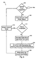
FIG. 5 , a flow diagram of an embodiment of aprocess 500 for feeding data into a playout device is shown. A timer interval is configured for by using a hardware or software timer of the computer executing this process. In this embodiment, the timer interval is 3ms. Instep 504, therepetitive process 500 begins once the interval timer has lapsed. Thesound card 420 is queried instep 508 to determine the status the sound card buffer. A minimum amount in the sound card buffer serves as a threshold to request additional data from the JB &PLC unit 408. This minimum threshold is set such that the sound card will not run out of data before more can be added through thisprocess 500. For example, the sound card buffer could hold 30ms of data. The threshold could be set to trigger when less than 10ms of data remains in the sound card buffer. - Where it is determined in
step 512 that the sound card buffer is not below a threshold, the interval timer is reset instep 516 and theprocess 500 begins over again. In the alternative, if the sound card buffer is below the threshold instep 512, processing continues to step 520 where a data block is requested from the JB &PLC unit 408. The block is formulated from the packets received from thepacket network 402. In some cases, the amount of sound in a packet is larger than the block size, while in other cases, the opposite is true. At the time of the request, the jitter buffer may not have a complete block of data received from thepacket network 402 as some of the packets may have been lost or not yet received. Where some of the block is still missing, it is recreated by the PLC using any number of algorithms, for example, zero insertion or interpolation. Instep 528, the data block is written into the sound card buffer before processing loops throughstep 516 to the beginning of theprocess 500. - Referring next to
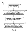
FIG. 6 , a flow diagram of an embodiment of aprocess 600 for receiving data from apacket network 402 and storing that data in a jitter buffer is shown. The depicted portion of the process begins instep 604 where a packet is received from thenetwork 402. In this embodiment, thenetwork 402 is the Internet. Arrival at thepacket communication device 404 triggers a process instep 608 where the packet is written into the JB &PLC unit 408. The written packet is analyzed to determine its temporal position in the jitter buffer instep 612. Instep 616, the packet is stored in the proper position of the jitter buffer. In some embodiments, the jitter buffer may store data out of sequence, but note the temporal positioning of each sequence such that it may be retrieved in proper temporal order. - A number of variations and modifications of the invention can also be used. For example, some of the above embodiments perform some tasks in software. Other embodiments could perform some or all of those tasks in hardware. One possibility is that the process of
FIG. 5 is partially implemented in hardware such that the sound card indicates when its buffer needs more data through a hardware or software interrupt to the operating system. - While the principles of the invention have been described above in connection with specific apparatuses and methods, it is to be clearly understood that this description is made only by way of example and not as limitation on the scope of the invention.
Claims (15)
- A method for feeding media data stored in a first buffer (408) to a second buffer (420), the media data being received as a plurality of packets from a packet communication network (402), the method comprising:querying the second buffer to determine an amount of media data in the second buffer;comparing the amount of media data in the second buffer with a threshold; the method being characterized in further comprising:responsive to determining that the amount of media data in the second buffer is less than the threshold, retrieving a block of the media data from said first buffer; andloading the retrieved block of the media data in the second buffer, wherein the threshold is adaptively determined based on the occurrence of one or more underruns in the second buffer.
- The method of claim 1, wherein the block of the media data retrieved from the first buffer includes data created using a packet loss concealment operation.
- The method of claim 1, wherein the step of retrieving comprises requesting the block of the media data from the first buffer.
- The method of claim 1, wherein the comparing step is performed once a time interval has lapsed.
- The method of claim 4, wherein the time interval is smaller than a playback time of the block of the media data retrieved from the first buffer or less than the time for playing out an amount of data received from the first buffer.
- The method of claim 1, further comprising a step of converting the media data from a first format to a second format, wherein the second format is compatible with a media playout device connectable to the second buffer.
- The method of claim 3, further comprising:determining that the block of the media data requested from the first buffer is larger than an amount of media data stored in the first buffer; andcreating additional media data using a packet loss concealment operation.
- The method of claim 1, further comprising a step of modifying an amount of data samples produced from the plurality of packets based on a playout sample rate.
- A computer-readable medium having computer-executable instructions for performing the computer-implementable method as defined in claim 1.
- A device (416) arranged between a first buffer (408) and a second buffer (420) for processing a media stream received as a plurality of packets from a packet communication network (402), the received packets being stored in the first buffer, the device being configured to:compare an amount of data in the second buffer with a threshold;responsive to the amount of data in the second buffer being less than the threshold, retrieve a portion of the media stream from the first buffer; andload the retrieved portion in the second buffer, wherein the threshold being adaptively determined based on the occurrence of one or more underruns in the second buffer.
- The device of claim 10, wherein the portion of the media stream retrieved from the first buffer includes data created using a packet loss concealment operation.
- The device of claim 10, further comprising an interval timer configured to trigger the comparison of the amount of data in the second buffer with a threshold once a time interval has lapsed.
- The device of claim 12, wherein the time interval is smaller than a playback time of an amount of media that is requested from the first buffer or less than the time for playing out an amount of data received from the first buffer.
- The device of claim 10, being further configured to convert the media data from a first format to a second format, wherein the second format is compatible with a media playout device connectable to the second buffer.
- The device of claim 10, being further configured to modify an amount of data samples produced from the plurality of packets based on a playout sample rate.
Applications Claiming Priority (3)
| Application Number | Priority Date | Filing Date | Title |
|---|---|---|---|
| US32717701P | 2001-10-03 | 2001-10-03 | |
| US10/262,531 US7453897B2 (en) | 2001-10-03 | 2002-09-30 | Network media playout |
| EP02800299A EP1440375B1 (en) | 2001-10-03 | 2002-10-03 | Network media playout |
Related Parent Applications (2)
| Application Number | Title | Priority Date | Filing Date |
|---|---|---|---|
| EP02800299A Division EP1440375B1 (en) | 2001-10-03 | 2002-10-03 | Network media playout |
| EP02800299.6 Division | 2002-10-03 |
Publications (3)
| Publication Number | Publication Date |
|---|---|
| EP2328091A2 EP2328091A2 (en) | 2011-06-01 |
| EP2328091A3 EP2328091A3 (en) | 2012-03-28 |
| EP2328091B1 true EP2328091B1 (en) | 2015-12-23 |
Family
ID=26949280
Family Applications (2)
| Application Number | Title | Priority Date | Filing Date |
|---|---|---|---|
| EP11156611.3A Expired - Lifetime EP2328091B1 (en) | 2001-10-03 | 2002-10-03 | Network media playout |
| EP02800299A Expired - Lifetime EP1440375B1 (en) | 2001-10-03 | 2002-10-03 | Network media playout |
Family Applications After (1)
| Application Number | Title | Priority Date | Filing Date |
|---|---|---|---|
| EP02800299A Expired - Lifetime EP1440375B1 (en) | 2001-10-03 | 2002-10-03 | Network media playout |
Country Status (6)
| Country | Link |
|---|---|
| US (1) | US7453897B2 (en) |
| EP (2) | EP2328091B1 (en) |
| CN (1) | CN100334571C (en) |
| AT (1) | ATE507526T1 (en) |
| DE (1) | DE60239885D1 (en) |
| WO (1) | WO2003029990A1 (en) |
Families Citing this family (33)
| Publication number | Priority date | Publication date | Assignee | Title |
|---|---|---|---|---|
| WO2002073937A2 (en) * | 2001-03-14 | 2002-09-19 | Mercury Computer Systems, Inc. | Wireless communications methods and systems for long-code and other spread spectrum waveform processing |
| US7161905B1 (en) * | 2001-05-03 | 2007-01-09 | Cisco Technology, Inc. | Method and system for managing time-sensitive packetized data streams at a receiver |
| US7110422B1 (en) * | 2002-01-29 | 2006-09-19 | At&T Corporation | Method and apparatus for managing voice call quality over packet networks |
| US20040181611A1 (en) * | 2003-03-14 | 2004-09-16 | Viresh Ratnakar | Multimedia streaming system for wireless handheld devices |
| CN100379224C (en) * | 2003-11-06 | 2008-04-02 | 明基电通股份有限公司 | Data controlling method for medium player system |
| CN1791055B (en) * | 2004-12-14 | 2010-04-07 | 腾讯科技(深圳)有限公司 | Method for decreasing data packet broadcast time-delay |
| US8949452B2 (en) * | 2005-04-07 | 2015-02-03 | Opanga Networks, Inc. | System and method for progressive download with minimal play latency |
| US8909807B2 (en) * | 2005-04-07 | 2014-12-09 | Opanga Networks, Inc. | System and method for progressive download using surplus network capacity |
| US7894489B2 (en) * | 2005-06-10 | 2011-02-22 | Symmetricom, Inc. | Adaptive play-out buffers and adaptive clock operation in packet networks |
| CN100391231C (en) * | 2005-12-06 | 2008-05-28 | 海信集团有限公司 | Domestic terminal apparatus capable of realizing flow medium data high speed transmission |
| JP2007235221A (en) * | 2006-02-27 | 2007-09-13 | Fujitsu Ltd | Fluctuation absorption buffer device |
| US7783773B2 (en) | 2006-07-24 | 2010-08-24 | Microsoft Corporation | Glitch-free media streaming |
| US9635315B2 (en) | 2006-08-07 | 2017-04-25 | Oovoo Llc | Video conferencing over IP networks |
| US8856371B2 (en) * | 2006-08-07 | 2014-10-07 | Oovoo Llc | Video conferencing over IP networks |
| US7768923B2 (en) * | 2007-02-09 | 2010-08-03 | Cisco Technology, Inc. | Packet aging in a wireless network |
| EP1962468B1 (en) * | 2007-02-14 | 2013-11-20 | Samsung Electronics Co., Ltd. | Apparatus and Method for Processing Data |
| KR101311931B1 (en) | 2007-02-14 | 2013-09-30 | 삼성전자주식회사 | Method for reproducing in real-time the file receiving in non real-time transfer protocol and video apparatus using the same |
| US8005466B2 (en) * | 2007-02-14 | 2011-08-23 | Samsung Electronics Co., Ltd. | Real time reproduction method of file being received according to non real time transfer protocol and a video apparatus thereof |
| KR101355798B1 (en) | 2007-05-30 | 2014-01-27 | 삼성전자주식회사 | Method for reproducing in real-time the file receiving in non real-time transfer protocol and video apparatus using the same |
| US8214453B2 (en) * | 2007-03-14 | 2012-07-03 | Steven Charles Estes | Concept and associated device enabling multi-camera video and audio recording for synchronization with long term ambulatory electroencephalography (EEG) in the home, office, or hospital environment |
| FR2916925B1 (en) * | 2007-05-30 | 2009-07-17 | Alcatel Lucent Sas | METHOD AND DEVICE FOR BUFFERING DATA PACKETS TRANSMITTED THROUGH PLESIOCHRONOUS COMMUNICATION. |
| US8355338B2 (en) * | 2009-07-14 | 2013-01-15 | Hong Kong Applied Science And Technology Research Institute Co. Ltd. | Method of processing sequential information in packets streamed over a network |
| CN102118645B (en) * | 2009-12-31 | 2014-12-10 | 康佳集团股份有限公司 | System and control method for playing MP3 arranged on set top box |
| US9137051B2 (en) * | 2010-12-17 | 2015-09-15 | Alcatel Lucent | Method and apparatus for reducing rendering latency for audio streaming applications using internet protocol communications networks |
| US9485533B2 (en) | 2013-03-13 | 2016-11-01 | Nagrastar Llc | Systems and methods for assembling and extracting command and control data |
| US9888283B2 (en) * | 2013-03-13 | 2018-02-06 | Nagrastar Llc | Systems and methods for performing transport I/O |
| US9647997B2 (en) | 2013-03-13 | 2017-05-09 | Nagrastar, Llc | USB interface for performing transport I/O |
| USD758372S1 (en) | 2013-03-13 | 2016-06-07 | Nagrastar Llc | Smart card interface |
| USD729808S1 (en) | 2013-03-13 | 2015-05-19 | Nagrastar Llc | Smart card interface |
| USD759022S1 (en) | 2013-03-13 | 2016-06-14 | Nagrastar Llc | Smart card interface |
| GB2521883B (en) | 2014-05-02 | 2016-03-30 | Imagination Tech Ltd | Media controller |
| USD780763S1 (en) | 2015-03-20 | 2017-03-07 | Nagrastar Llc | Smart card interface |
| USD864968S1 (en) | 2015-04-30 | 2019-10-29 | Echostar Technologies L.L.C. | Smart card interface |
Citations (2)
| Publication number | Priority date | Publication date | Assignee | Title |
|---|---|---|---|---|
| GB2349296A (en) * | 1999-04-21 | 2000-10-25 | 3Com Corp | Reduction of imbalance in transmsit queues in a network switch |
| US6167032A (en) * | 1997-11-07 | 2000-12-26 | International Business Machines Corporation | System and method for avoiding host transmit underruns in a communication network |
Family Cites Families (30)
| Publication number | Priority date | Publication date | Assignee | Title |
|---|---|---|---|---|
| US4945548A (en) * | 1988-04-28 | 1990-07-31 | Digital Equipment Corporation | Method and apparatus for detecting impending overflow and/or underrun of elasticity buffer |
| US5127001A (en) * | 1990-06-22 | 1992-06-30 | Unisys Corporation | Conference call arrangement for distributed network |
| JPH04369942A (en) | 1991-06-19 | 1992-12-22 | Hitachi Ltd | Data communication system |
| KR960008470B1 (en) * | 1994-01-18 | 1996-06-26 | Daewoo Electronics Co Ltd | Apparatus for transferring bit stream data adaptively in the moving picture |
| AU1572995A (en) | 1994-02-11 | 1995-08-29 | Newbridge Networks Corporation | Method of dynamically compensating for variable transmission delays in packet networks |
| US5825771A (en) | 1994-11-10 | 1998-10-20 | Vocaltec Ltd. | Audio transceiver |
| US5793980A (en) * | 1994-11-30 | 1998-08-11 | Realnetworks, Inc. | Audio-on-demand communication system |
| US5673416A (en) * | 1995-06-07 | 1997-09-30 | Seiko Epson Corporation | Memory request and control unit including a mechanism for issuing and removing requests for memory access |
| EP0839421A4 (en) * | 1995-07-19 | 2001-07-18 | Fujitsu Network Communications | Allocated and dynamic switch flow control |
| US5889764A (en) * | 1995-08-31 | 1999-03-30 | Intel Corporation | Low-latency multi-party audio chat |
| US5983278A (en) * | 1996-04-19 | 1999-11-09 | Lucent Technologies Inc. | Low-loss, fair bandwidth allocation flow control in a packet switch |
| US6366959B1 (en) * | 1997-10-01 | 2002-04-02 | 3Com Corporation | Method and apparatus for real time communication system buffer size and error correction coding selection |
| US6912224B1 (en) * | 1997-11-02 | 2005-06-28 | International Business Machines Corporation | Adaptive playout buffer and method for improved data communication |
| US6480667B1 (en) * | 1997-12-23 | 2002-11-12 | Intel Corporation | Method of time shifting to simultaneously record and play a data stream |
| US6092108A (en) * | 1998-03-19 | 2000-07-18 | Diplacido; Bruno | Dynamic threshold packet filtering of application processor frames |
| US6512761B1 (en) * | 1999-02-02 | 2003-01-28 | 3Com Corporation | System for adjusting billing for real-time media transmissions based on delay |
| EP1188285B1 (en) * | 1999-04-13 | 2012-06-13 | Broadcom Corporation | Gateway with voice |
| US6665751B1 (en) * | 1999-04-17 | 2003-12-16 | International Business Machines Corporation | Streaming media player varying a play speed from an original to a maximum allowable slowdown proportionally in accordance with a buffer state |
| EP1088303B1 (en) * | 1999-04-19 | 2006-08-02 | AT & T Corp. | Method and apparatus for performing frame erasure concealment |
| US6625656B2 (en) * | 1999-05-04 | 2003-09-23 | Enounce, Incorporated | Method and apparatus for continuous playback or distribution of information including audio-visual streamed multimedia |
| US6658027B1 (en) * | 1999-08-16 | 2003-12-02 | Nortel Networks Limited | Jitter buffer management |
| FI108692B (en) * | 1999-12-30 | 2002-02-28 | Nokia Corp | Method and apparatus for scheduling processing of data packets |
| GB2358558B (en) * | 2000-01-18 | 2003-10-15 | Mitel Corp | Packet loss compensation method using injection of spectrally shaped noise |
| GB2360178B (en) * | 2000-03-06 | 2004-04-14 | Mitel Corp | Sub-packet insertion for packet loss compensation in Voice Over IP networks |
| US6775301B1 (en) * | 2000-03-08 | 2004-08-10 | 3Com Corporation | System and method for compensating for channel jitter |
| US7246057B1 (en) | 2000-05-31 | 2007-07-17 | Telefonaktiebolaget Lm Ericsson (Publ) | System for handling variations in the reception of a speech signal consisting of packets |
| US7373413B1 (en) * | 2000-06-28 | 2008-05-13 | Cisco Technology, Inc. | Devices and methods for minimizing start up delay in transmission of streaming media |
| US7161905B1 (en) * | 2001-05-03 | 2007-01-09 | Cisco Technology, Inc. | Method and system for managing time-sensitive packetized data streams at a receiver |
| US20020172352A1 (en) * | 2001-05-16 | 2002-11-21 | Ofir Mecayten | Non-embedded acoustic echo cancellation |
| US6977948B1 (en) * | 2001-08-13 | 2005-12-20 | Utstarcom, Inc. | Jitter buffer state management system for data transmitted between synchronous and asynchronous data networks |
-
2002
- 2002-09-30 US US10/262,531 patent/US7453897B2/en active Active
- 2002-10-03 EP EP11156611.3A patent/EP2328091B1/en not_active Expired - Lifetime
- 2002-10-03 DE DE60239885T patent/DE60239885D1/en not_active Expired - Lifetime
- 2002-10-03 AT AT02800299T patent/ATE507526T1/en not_active IP Right Cessation
- 2002-10-03 EP EP02800299A patent/EP1440375B1/en not_active Expired - Lifetime
- 2002-10-03 WO PCT/SE2002/001798 patent/WO2003029990A1/en not_active Application Discontinuation
- 2002-10-03 CN CNB028196317A patent/CN100334571C/en not_active Expired - Lifetime
Patent Citations (2)
| Publication number | Priority date | Publication date | Assignee | Title |
|---|---|---|---|---|
| US6167032A (en) * | 1997-11-07 | 2000-12-26 | International Business Machines Corporation | System and method for avoiding host transmit underruns in a communication network |
| GB2349296A (en) * | 1999-04-21 | 2000-10-25 | 3Com Corp | Reduction of imbalance in transmsit queues in a network switch |
Also Published As
| Publication number | Publication date |
|---|---|
| US7453897B2 (en) | 2008-11-18 |
| EP2328091A3 (en) | 2012-03-28 |
| CN100334571C (en) | 2007-08-29 |
| EP2328091A2 (en) | 2011-06-01 |
| US20030091160A1 (en) | 2003-05-15 |
| DE60239885D1 (en) | 2011-06-09 |
| WO2003029990A1 (en) | 2003-04-10 |
| EP1440375B1 (en) | 2011-04-27 |
| CN1564984A (en) | 2005-01-12 |
| EP1440375A1 (en) | 2004-07-28 |
| ATE507526T1 (en) | 2011-05-15 |
Similar Documents
| Publication | Publication Date | Title |
|---|---|---|
| EP2328091B1 (en) | Network media playout | |
| US7450601B2 (en) | Method and communication apparatus for controlling a jitter buffer | |
| US8279884B1 (en) | Integrated adaptive jitter buffer | |
| US7162418B2 (en) | Presentation-quality buffering process for real-time audio | |
| US7283585B2 (en) | Multiple data rate communication system | |
| US10659380B2 (en) | Media buffering | |
| US7573907B2 (en) | Discontinuous transmission of speech signals | |
| US7072291B1 (en) | Devices, softwares and methods for redundantly encoding a data stream for network transmission with adjustable redundant-coding delay | |
| AU2008330261A1 (en) | Play-out delay estimation | |
| US7916742B1 (en) | Dynamic jitter buffer calibration | |
| US8457182B2 (en) | Multiple data rate communication system | |
| KR100677179B1 (en) | Dynamic latency management for ?? telephony | |
| AU2002310383A1 (en) | Dynamic latency management for IP telephony | |
| EP2070294B1 (en) | Supporting a decoding of frames | |
| US20080170562A1 (en) | Method and communication device for improving the performance of a VoIP call |
Legal Events
| Date | Code | Title | Description |
|---|---|---|---|
| PUAI | Public reference made under article 153(3) epc to a published international application that has entered the european phase |
Free format text: ORIGINAL CODE: 0009012 |
|
| AC | Divisional application: reference to earlier application |
Ref document number: 1440375 Country of ref document: EP Kind code of ref document: P |
|
| AK | Designated contracting states |
Kind code of ref document: A2 Designated state(s): AT BE BG CH CY CZ DE DK EE ES FI FR GB GR IE IT LI LU MC NL PT SE SK TR |
|
| PUAL | Search report despatched |
Free format text: ORIGINAL CODE: 0009013 |
|
| AK | Designated contracting states |
Kind code of ref document: A3 Designated state(s): AT BE BG CH CY CZ DE DK EE ES FI FR GB GR IE IT LI LU MC NL PT SE SK TR |
|
| RIC1 | Information provided on ipc code assigned before grant |
Ipc: H04L 12/26 20060101ALI20120222BHEP Ipc: G06F 13/00 20060101AFI20120222BHEP Ipc: H04L 12/64 20060101ALI20120222BHEP Ipc: H04L 29/06 20060101ALI20120222BHEP |
|
| RAP1 | Party data changed (applicant data changed or rights of an application transferred) |
Owner name: GOOGLE INC. |
|
| 17P | Request for examination filed |
Effective date: 20120925 |
|
| 17Q | First examination report despatched |
Effective date: 20130426 |
|
| GRAP | Despatch of communication of intention to grant a patent |
Free format text: ORIGINAL CODE: EPIDOSNIGR1 |
|
| INTG | Intention to grant announced |
Effective date: 20150421 |
|
| GRAS | Grant fee paid |
Free format text: ORIGINAL CODE: EPIDOSNIGR3 |
|
| GRAA | (expected) grant |
Free format text: ORIGINAL CODE: 0009210 |
|
| AC | Divisional application: reference to earlier application |
Ref document number: 1440375 Country of ref document: EP Kind code of ref document: P |
|
| AK | Designated contracting states |
Kind code of ref document: B1 Designated state(s): AT BE BG CH CY CZ DE DK EE ES FI FR GB GR IE IT LI LU MC NL PT SE SK TR |
|
| REG | Reference to a national code |
Ref country code: GB Ref legal event code: FG4D |
|
| REG | Reference to a national code |
Ref country code: CH Ref legal event code: EP |
|
| REG | Reference to a national code |
Ref country code: IE Ref legal event code: FG4D |
|
| REG | Reference to a national code |
Ref country code: AT Ref legal event code: REF Ref document number: 766819 Country of ref document: AT Kind code of ref document: T Effective date: 20160115 |
|
| REG | Reference to a national code |
Ref country code: DE Ref legal event code: R096 Ref document number: 60247697 Country of ref document: DE |
|
| REG | Reference to a national code |
Ref country code: NL Ref legal event code: MP Effective date: 20151223 |
|
| REG | Reference to a national code |
Ref country code: AT Ref legal event code: MK05 Ref document number: 766819 Country of ref document: AT Kind code of ref document: T Effective date: 20151223 |
|
| PG25 | Lapsed in a contracting state [announced via postgrant information from national office to epo] |
Ref country code: FI Free format text: LAPSE BECAUSE OF FAILURE TO SUBMIT A TRANSLATION OF THE DESCRIPTION OR TO PAY THE FEE WITHIN THE PRESCRIBED TIME-LIMIT Effective date: 20151223 Ref country code: NL Free format text: LAPSE BECAUSE OF FAILURE TO SUBMIT A TRANSLATION OF THE DESCRIPTION OR TO PAY THE FEE WITHIN THE PRESCRIBED TIME-LIMIT Effective date: 20151223 Ref country code: SE Free format text: LAPSE BECAUSE OF FAILURE TO SUBMIT A TRANSLATION OF THE DESCRIPTION OR TO PAY THE FEE WITHIN THE PRESCRIBED TIME-LIMIT Effective date: 20151223 Ref country code: GR Free format text: LAPSE BECAUSE OF FAILURE TO SUBMIT A TRANSLATION OF THE DESCRIPTION OR TO PAY THE FEE WITHIN THE PRESCRIBED TIME-LIMIT Effective date: 20160324 |
|
| PG25 | Lapsed in a contracting state [announced via postgrant information from national office to epo] |
Ref country code: CZ Free format text: LAPSE BECAUSE OF FAILURE TO SUBMIT A TRANSLATION OF THE DESCRIPTION OR TO PAY THE FEE WITHIN THE PRESCRIBED TIME-LIMIT Effective date: 20151223 Ref country code: IT Free format text: LAPSE BECAUSE OF FAILURE TO SUBMIT A TRANSLATION OF THE DESCRIPTION OR TO PAY THE FEE WITHIN THE PRESCRIBED TIME-LIMIT Effective date: 20151223 Ref country code: ES Free format text: LAPSE BECAUSE OF FAILURE TO SUBMIT A TRANSLATION OF THE DESCRIPTION OR TO PAY THE FEE WITHIN THE PRESCRIBED TIME-LIMIT Effective date: 20151223 |
|
| PG25 | Lapsed in a contracting state [announced via postgrant information from national office to epo] |
Ref country code: EE Free format text: LAPSE BECAUSE OF FAILURE TO SUBMIT A TRANSLATION OF THE DESCRIPTION OR TO PAY THE FEE WITHIN THE PRESCRIBED TIME-LIMIT Effective date: 20151223 Ref country code: AT Free format text: LAPSE BECAUSE OF FAILURE TO SUBMIT A TRANSLATION OF THE DESCRIPTION OR TO PAY THE FEE WITHIN THE PRESCRIBED TIME-LIMIT Effective date: 20151223 Ref country code: PT Free format text: LAPSE BECAUSE OF FAILURE TO SUBMIT A TRANSLATION OF THE DESCRIPTION OR TO PAY THE FEE WITHIN THE PRESCRIBED TIME-LIMIT Effective date: 20160426 Ref country code: SK Free format text: LAPSE BECAUSE OF FAILURE TO SUBMIT A TRANSLATION OF THE DESCRIPTION OR TO PAY THE FEE WITHIN THE PRESCRIBED TIME-LIMIT Effective date: 20151223 |
|
| REG | Reference to a national code |
Ref country code: DE Ref legal event code: R097 Ref document number: 60247697 Country of ref document: DE |
|
| PLBE | No opposition filed within time limit |
Free format text: ORIGINAL CODE: 0009261 |
|
| STAA | Information on the status of an ep patent application or granted ep patent |
Free format text: STATUS: NO OPPOSITION FILED WITHIN TIME LIMIT |
|
| PG25 | Lapsed in a contracting state [announced via postgrant information from national office to epo] |
Ref country code: DK Free format text: LAPSE BECAUSE OF FAILURE TO SUBMIT A TRANSLATION OF THE DESCRIPTION OR TO PAY THE FEE WITHIN THE PRESCRIBED TIME-LIMIT Effective date: 20151223 |
|
| 26N | No opposition filed |
Effective date: 20160926 |
|
| PG25 | Lapsed in a contracting state [announced via postgrant information from national office to epo] |
Ref country code: BE Free format text: LAPSE BECAUSE OF FAILURE TO SUBMIT A TRANSLATION OF THE DESCRIPTION OR TO PAY THE FEE WITHIN THE PRESCRIBED TIME-LIMIT Effective date: 20151223 |
|
| REG | Reference to a national code |
Ref country code: CH Ref legal event code: PL |
|
| GBPC | Gb: european patent ceased through non-payment of renewal fee |
Effective date: 20161003 |
|
| REG | Reference to a national code |
Ref country code: IE Ref legal event code: MM4A |
|
| REG | Reference to a national code |
Ref country code: FR Ref legal event code: ST Effective date: 20170630 |
|
| PG25 | Lapsed in a contracting state [announced via postgrant information from national office to epo] |
Ref country code: FR Free format text: LAPSE BECAUSE OF NON-PAYMENT OF DUE FEES Effective date: 20161102 Ref country code: GB Free format text: LAPSE BECAUSE OF NON-PAYMENT OF DUE FEES Effective date: 20161003 Ref country code: CH Free format text: LAPSE BECAUSE OF NON-PAYMENT OF DUE FEES Effective date: 20161031 Ref country code: LI Free format text: LAPSE BECAUSE OF NON-PAYMENT OF DUE FEES Effective date: 20161031 |
|
| PG25 | Lapsed in a contracting state [announced via postgrant information from national office to epo] |
Ref country code: LU Free format text: LAPSE BECAUSE OF NON-PAYMENT OF DUE FEES Effective date: 20161003 |
|
| PG25 | Lapsed in a contracting state [announced via postgrant information from national office to epo] |
Ref country code: IE Free format text: LAPSE BECAUSE OF NON-PAYMENT OF DUE FEES Effective date: 20161003 |
|
| REG | Reference to a national code |
Ref country code: DE Ref legal event code: R082 Ref document number: 60247697 Country of ref document: DE Representative=s name: SPLANEMANN PATENTANWAELTE PARTNERSCHAFT MBB, DE Ref country code: DE Ref legal event code: R081 Ref document number: 60247697 Country of ref document: DE Owner name: GOOGLE LLC (N.D.GES.D. STAATES DELAWARE), MOUN, US Free format text: FORMER OWNER: GOOGLE, INC., MOUNTAIN VIEW, CALIF., US |
|
| PG25 | Lapsed in a contracting state [announced via postgrant information from national office to epo] |
Ref country code: CY Free format text: LAPSE BECAUSE OF FAILURE TO SUBMIT A TRANSLATION OF THE DESCRIPTION OR TO PAY THE FEE WITHIN THE PRESCRIBED TIME-LIMIT Effective date: 20151223 |
|
| PG25 | Lapsed in a contracting state [announced via postgrant information from national office to epo] |
Ref country code: TR Free format text: LAPSE BECAUSE OF FAILURE TO SUBMIT A TRANSLATION OF THE DESCRIPTION OR TO PAY THE FEE WITHIN THE PRESCRIBED TIME-LIMIT Effective date: 20151223 Ref country code: MC Free format text: LAPSE BECAUSE OF FAILURE TO SUBMIT A TRANSLATION OF THE DESCRIPTION OR TO PAY THE FEE WITHIN THE PRESCRIBED TIME-LIMIT Effective date: 20151223 |
|
| PG25 | Lapsed in a contracting state [announced via postgrant information from national office to epo] |
Ref country code: BG Free format text: LAPSE BECAUSE OF FAILURE TO SUBMIT A TRANSLATION OF THE DESCRIPTION OR TO PAY THE FEE WITHIN THE PRESCRIBED TIME-LIMIT Effective date: 20151223 |
|
| PGFP | Annual fee paid to national office [announced via postgrant information from national office to epo] |
Ref country code: DE Payment date: 20211027 Year of fee payment: 20 |
|
| REG | Reference to a national code |
Ref country code: DE Ref legal event code: R071 Ref document number: 60247697 Country of ref document: DE |
|
| P01 | Opt-out of the competence of the unified patent court (upc) registered |
Effective date: 20230505 |