EP2328044A1 - Watch case - Google Patents
Watch case Download PDFInfo
- Publication number
- EP2328044A1 EP2328044A1 EP09405202A EP09405202A EP2328044A1 EP 2328044 A1 EP2328044 A1 EP 2328044A1 EP 09405202 A EP09405202 A EP 09405202A EP 09405202 A EP09405202 A EP 09405202A EP 2328044 A1 EP2328044 A1 EP 2328044A1
- Authority
- EP
- European Patent Office
- Prior art keywords
- watch case
- case according
- metal member
- elastic metal
- opening
- Prior art date
- Legal status (The legal status is an assumption and is not a legal conclusion. Google has not performed a legal analysis and makes no representation as to the accuracy of the status listed.)
- Withdrawn
Links
Images


Classifications
-
- G—PHYSICS
- G04—HOROLOGY
- G04B—MECHANICALLY-DRIVEN CLOCKS OR WATCHES; MECHANICAL PARTS OF CLOCKS OR WATCHES IN GENERAL; TIME PIECES USING THE POSITION OF THE SUN, MOON OR STARS
- G04B37/00—Cases
- G04B37/04—Mounting the clockwork in the case; Shock absorbing mountings
- G04B37/05—Fixed mountings for pocket or wrist watches
- G04B37/052—Fixed mountings for pocket or wrist watches with shock damping means not related to the winding stem
-
- G—PHYSICS
- G04—HOROLOGY
- G04B—MECHANICALLY-DRIVEN CLOCKS OR WATCHES; MECHANICAL PARTS OF CLOCKS OR WATCHES IN GENERAL; TIME PIECES USING THE POSITION OF THE SUN, MOON OR STARS
- G04B37/00—Cases
- G04B37/08—Hermetic sealing of openings, joints, passages or slits
- G04B37/11—Hermetic sealing of openings, joints, passages or slits of the back cover of pocket or wrist watches
-
- G—PHYSICS
- G04—HOROLOGY
- G04B—MECHANICALLY-DRIVEN CLOCKS OR WATCHES; MECHANICAL PARTS OF CLOCKS OR WATCHES IN GENERAL; TIME PIECES USING THE POSITION OF THE SUN, MOON OR STARS
- G04B39/00—Watch crystals; Fastening or sealing of crystals; Clock glasses
- G04B39/02—Sealing crystals or glasses
-
- G—PHYSICS
- G04—HOROLOGY
- G04B—MECHANICALLY-DRIVEN CLOCKS OR WATCHES; MECHANICAL PARTS OF CLOCKS OR WATCHES IN GENERAL; TIME PIECES USING THE POSITION OF THE SUN, MOON OR STARS
- G04B43/00—Protecting clockworks by shields or other means against external influences, e.g. magnetic fields
- G04B43/002—Component shock protection arrangements
-
- G—PHYSICS
- G04—HOROLOGY
- G04G—ELECTRONIC TIME-PIECES
- G04G17/00—Structural details; Housings
- G04G17/02—Component assemblies
-
- G—PHYSICS
- G04—HOROLOGY
- G04G—ELECTRONIC TIME-PIECES
- G04G17/00—Structural details; Housings
- G04G17/08—Housings
-
- G—PHYSICS
- G04—HOROLOGY
- G04G—ELECTRONIC TIME-PIECES
- G04G21/00—Input or output devices integrated in time-pieces
Definitions
- the present invention relates to a watch case comprising a case whose at least one opening is closed by a telescope and / or an ice, or by a bottom, and in which at least one of the closing elements of the opening is connected at the middle part by an elastic metal member in the form of a ring or endless frame and of recessed straight section defined by the contour of a non-rectilinear wall of controlled thickness, the ends of which are integral with the periphery of said closure element, respectively of the middle part.
- the documents CH630220 and CH686600 describe means for moving an ice at variable frequencies by means of an electromagnet or a piezoresistive element. There is mention of a thin annular ring which makes it possible to elastically suspend the ice. The mobility of the ice relative to the middle part is very limited both in the plane of the ice and in the plane perpendicular to the ice, and the watertightness is not guaranteed by the construction.
- WO 2008027140 describes a mobile (tilting) bezel to activate different functions.
- the mobility of this bezel is due to a piece of rubber or polyurethane, which however does not provide the seal and which we can doubt the reliability in the long term.
- the object of the present invention is to give a controlled freedom of movement in direction and amplitude to the closure element mounted on the caseband, bezel and / or ice or bottom, depending on the role that one wishes to give to this closure element.
- the subject of the present invention is a watch case according to claim 1.
- the profile of said wall comprises a plurality of alternating annular folds whose number is between 1 and 10.
- the thickness e of said wall is constant and is between 10 .mu.m and 200 .mu.m, the width a of the annular fold is between 0.2mm and 4mm, the pitch p of the annular fold being between> 40 .mu.m and 2.5 mm, to give said closure member freedom of movement, stiffness and orientation controlled with respect to the plane of the opening.
- the ends of the profile of said wall are sealingly connected to the periphery of said closure element, respectively of the middle part.
- seals are mounted between the respective cylindrical ends of said wall adjacent to cylindrical seats of said closure member, respectively of said middle and compression rings or frames in view of to seal the box.
- Metal bellows are thin metal wall elements with a carefully chosen profile to provide flexibility, stiffness and resistance data to the set. There are several types of metal bellows: rolled, hydro-formed, chemically deposited, electro-formed, this list being non-exhaustive.
- Electro-formed bellows are particularly interesting. Their manufacturing technique is more than 150 years old, but it is only in recent years that components with complex geometries of low thickness (of the order of ten microns) and well controlled have been obtained.
- the challenge in thickness control is to play with deposition parameters (eg interelectrode distances, nature of electrodes, agitation and bath chemistry, etc.) so as to minimize variations in thickness due to variations. of current density along a geometry with strong changes of curvature.
- the precise control of the geometry and the thickness makes it possible to develop bellows with adequate stiffness and able to give the closing element of the opening of the middle part a freedom of movement with respect to the plane of this opening.
- the companies Servometer or Nicoform are examples of suppliers of miniature electro-shaped bellows. These bellows are described for example in the US 3'187'639 and US 5,932,360 .
- the websites www.servometer.com or www.nicoform.com also give a lot of information about the technique and the materials
- bellows can be assembled to other rigid parts to facilitate their integration. It must be ensured that the chosen methods of assembly and the materials used are adapted to the stresses that will undergo the assembly without the associated function being pejorated.
- the assemblies can be made by bonding, brazing or welding by electron bombardment or by laser. If, for example, it is desired to guarantee a seal, the bonding or a solder with tin may prove to be insufficient. In addition, depending on the materials used, too high a temperature in the process can degrade their properties. If the stresses require good corrosion resistance, care must be taken to use suitable materials or pairs of materials.
- the form of execution illustrated by the figure 1 relates to the attachment of a watch crystal 1 to close the upper opening of a middle part 2 of a watch case.
- the watch glass 1 is connected to the middle part 2 by an elastic metal member 3 in the form of a ring of recessed straight section defined by the profile of a non-rectilinear wall of constant thickness, constituting a metallic bellows whose ends 3a, 3b are integral with the periphery of the glass 1, respectively of the middle part 2.
- An annular seal 4 surrounds the periphery of the ice as well as the end 3a of the metal bellows 3.
- the other end 3b of the bellows 3 is fixed in the same way against a cylindrical portion of the middle 2 by an annular seal 6 compressed by a titanium ring 7.
- a bezel 8 is fixed on the middle part by a ring 9 fixed against a carried on the external lateral face of the titanium ring 7.
- the ice 1 is held only by one end of the bellows 3, so that it is suspended elastically on the middle part 2.
- This assembly can then act as a shock absorber; it may be able to switch to enable functions; or else serve as speaker, pressure sensitive system (balance, barometer, etc.), without this enumeration is limiting.
- the figure 5 illustrates a bellows 23 incorporated between the middle part 24 and the glass 21, under the bezel 28, with a stamp or a gong 25 and a deflection element 26 of the patch or gong towards the ice 21 and a bearing element 29 against the ice 21.
- the attachment of the ice with a flexible bellows makes it possible to transmit to the outside vibrations generated inside the box (or conversely), while preserving the tightness of the box.
- the ice-shield assembly may advantageously be sized so that its natural frequency is at higher values than the frequency band of the transmitted signal (from 100 to 4000 Hz for example); this one does not find it thus degraded nor modified (distortion).
- the geometry of the bellows does not in any way harm the aesthetics of the room and can be integrated easily.
- the thickness of the wall of the bellows is of the order of 50 microns, which guarantees a sufficient lateral robustness.
- protections are nevertheless provided by the presence of vertical stops b1 and b2 or side b3 to prevent damage to the system during very strong external stresses.
- FIG 6 Referring to a variant in which an annular bellows 33 is disposed between the bottom 40, to which it is fixed by welding, and the middle part 34. The other end of the bellows is clamped between two rings 35, 36 tightened against each other. the other by a ring 37 fixed to the middle part 34 by screws 38. A compression seal J seals the system.
- the elastic metal member 3, 23, 33 in the form of a ring of recessed straight section defined by the profile of a non-rectilinear wall of constant thickness, constituting a bellows when it comprises at least two adjacent folds forming a meander ( figure 7 ).
- Our goal is to be able to obtain a self-guided metal organ, ie not susceptible to flaming or deforming, integrable to a watch box and which has a stiffness adapted to the desired function.
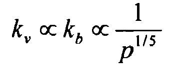
- stiffnesses are defined by k, their index gives the vertical direction v, horizontal h or tilting 6. Stiffness according to e according to a according to p Vertical and tilting k v ⁇ k b ⁇ e 3 k v ⁇ k b ⁇ 1 at 5 / 2 k v ⁇ k b ⁇ 1 p 1 / 5 horizontal h k, ⁇ e 3/2 k h ⁇ 1 at k h ⁇ 1 p 2 / 5
- n 0.5
- guaranteeing the autoguiding of the system is equivalent to minimizing n and p for values of e and a linked to a stiffness defined by the physical function of the bellows.
- Example 2 Max terminal Typical stiffness 50 N / mm 500 N / mm e 10 ⁇ m 35 ⁇ m 50 ⁇ m 200 ⁇ m at 0.1 mm 1 mm 0.8 mm 4 mm p > 80 ⁇ m 0, 9 mm 0.8 mm 5 mm not 0, 5 3 1 ⁇ 5
Abstract
Description
La présente invention se rapporte à une boîte de montre comprenant une carrure dont au moins une ouverture est fermée par une lunette et/ou une glace, ou par un fond, et dans laquelle au moins un des éléments de fermeture de l'ouverture est relié à la carrure par un organe métallique élastique en forme de bague ou de cadre sans fin et de section droite évidée définie par le contour d'une paroi non rectiligne d'épaisseur contrôlée dont les extrémités sont solidaires de la périphérie dudit élément de fermeture, respectivement de la carrure.The present invention relates to a watch case comprising a case whose at least one opening is closed by a telescope and / or an ice, or by a bottom, and in which at least one of the closing elements of the opening is connected at the middle part by an elastic metal member in the form of a ring or endless frame and of recessed straight section defined by the contour of a non-rectilinear wall of controlled thickness, the ends of which are integral with the periphery of said closure element, respectively of the middle part.
Il peut être avantageux de rendre mobile la glace ou le fond d'une montre par rapport à la carrure, et ce sans prétériter l'étanchéité de la boîte, par exemple pour améliorer la résistance aux chocs, ou pour réaliser de nouvelles fonctions. Les solutions proposées dans l'état de l'art ne sont pas satisfaisantes à cet égard.It may be advantageous to make the ice or the bottom of a watch movable relative to the middle part, and without pre-sealing the box, for example to improve impact resistance, or to perform new functions. The solutions proposed in the state of the art are not satisfactory in this respect.
Les documents
On a proposé dans le
Le document
Le but de la présente invention est de donner une liberté de mouvement contrôlée en direction et en amplitude à l'élément de fermeture monté sur la carrure, lunette et/ou glace ou encore fond, en fonction du rôle que l'on désire conférer à cet élément de fermeture.The object of the present invention is to give a controlled freedom of movement in direction and amplitude to the closure element mounted on the caseband, bezel and / or ice or bottom, depending on the role that one wishes to give to this closure element.
A cet effet, la présente invention a pour objet une boîte de montre selon la revendication 1.For this purpose, the subject of the present invention is a watch case according to
Avantageusement, le profil de ladite paroi comporte une pluralité de plis annulaires alternés dont le nombre est compris entre 1 et 10.Advantageously, the profile of said wall comprises a plurality of alternating annular folds whose number is between 1 and 10.
De préférence, l'épaisseur e de ladite paroi est constante et comprise entre 10µm et 200µm, la largeur a du pli annulaire est comprise entre 0,2mm et 4mm, le pas p du pli annulaire étant compris entre >40µm et 2,5mm, pour donner audit élément de fermeture une liberté de mouvement, de raideur et d'orientation contrôlées par rapport au plan de l'ouverture.Preferably, the thickness e of said wall is constant and is between 10 .mu.m and 200 .mu.m, the width a of the annular fold is between 0.2mm and 4mm, the pitch p of the annular fold being between> 40 .mu.m and 2.5 mm, to give said closure member freedom of movement, stiffness and orientation controlled with respect to the plane of the opening.
Plus avantageusement encore, les extrémités du profil de ladite paroi sont reliées de façon étanche à la périphérie dudit élément de fermeture, respectivement de la carrure.More preferably, the ends of the profile of said wall are sealingly connected to the periphery of said closure element, respectively of the middle part.
Selon une forme d'exécution préférée de l'invention, des joints d'étanchéité sont montés entre les extrémités cylindriques respectives de ladite paroi adjacente à des sièges cylindriques dudit élément de fermeture, respectivement de ladite carrure et des bagues ou cadres de compression en vue d'assurer l'étanchéité de ladite boîte.According to a preferred embodiment of the invention, seals are mounted between the respective cylindrical ends of said wall adjacent to cylindrical seats of said closure member, respectively of said middle and compression rings or frames in view of to seal the box.
D'autres particularités et caractéristiques de la présente invention apparaîtront dans la description suivante et les dessins annexés qui illustrent, schématiquement et à titre d'exemple, différentes formes d'exécution et variantes de la présente invention.
- La
figure 1 est une vue partielle en coupe d'une première forme d'exécution; - la
figure 2 est une vue en coupe d'une variante de lafigure 1 ; - la
figure 3 est une vue en coupe du schéma de principe d'une autre forme d'exécution; - la
figure 4 est une vue en coupe d'une forme d'exécution relative à une boîte de montre carrée ou rectangulaire; - la
figure 4a est une vue en perspective éclatée de lafigure 4 ; - la
figure 5 est une vue en coupe d'une utilisation particulière de la boîte de montre selon l'invention; - la
figure 6 est une vue en coupe d'une autre forme d'exécution de l'invention; - la
figure 7 est un schéma d'un soufflet sur lequel sont indiqués les différents paramètres de ce soufflet.
- The
figure 1 is a partial sectional view of a first embodiment; - the
figure 2 is a sectional view of a variant of thefigure 1 ; - the
figure 3 is a sectional view of the schematic diagram of another embodiment; - the
figure 4 is a sectional view of an embodiment relating to a square or rectangular watch case; - the
figure 4a is an exploded perspective view of thefigure 4 ; - the
figure 5 is a sectional view of a particular use of the watch case according to the invention; - the
figure 6 is a sectional view of another embodiment of the invention; - the
figure 7 is a diagram of a bellows on which are indicated the different parameters of this bellows.
L'organe métallique élastique, en forme de bague ou de cadre sans fin et de section droite évidée définie par le profil d'une paroi non rectiligne, avantageusement d'épaisseur sensiblement constante, dont les extrémités sont solidaires respectivement de la périphérie d'un élément de fermeture et d'une ouverture de la carrure d'une boîte de montre selon la présente invention, forme un soufflet comprenant au moins un pli annulaire engendré par une courbure dont l'arc décrit un angle compris entre 90° et 180°, pour donner audit élément de fermeture une liberté de mouvement par rapport au plan de l'ouverture de la carrure.The elastic metal member, ring-shaped or endless frame and recessed cross-section defined by the profile of a non-rectilinear wall, preferably substantially constant thickness, the ends of which are secured respectively to the periphery of a closure element and an opening of the middle of a watch case according to the present invention, forms a bellows comprising at least one annular fold generated by a curvature whose arc describes an angle of between 90 ° and 180 °, to give said closure member freedom of movement relative to the plane of the opening of the middle part.
Les soufflets métalliques sont des éléments formés d'une mince paroi en métal, avec un profil soigneusement choisi pour conférer une souplesse, une raideur et une résistance données à l'ensemble. Il existe plusieurs types de soufflets métalliques: roulés, hydro-formés, déposés chimiquement, électro-formés, cette liste étant non-exhaustive.Metal bellows are thin metal wall elements with a carefully chosen profile to provide flexibility, stiffness and resistance data to the set. There are several types of metal bellows: rolled, hydro-formed, chemically deposited, electro-formed, this list being non-exhaustive.
Les soufflets électro-formés sont particulièrement intéressants. Leur technique de fabrication est vieille de plus de 150 ans, mais c'est uniquement ces dernières années que des composants à géométries complexes d'épaisseur faible (de l'ordre de la dizaine de microns) et bien contrôlée ont pu être obtenus. Le défi dans le contrôle de l'épaisseur consiste à jouer avec les paramètres de dépôt (par ex. distances interélectrodes, nature des électrodes, agitation et composition chimique du bain, etc.) de façon à minimiser les variations d'épaisseur liées aux variations de densité de courant le long d'une géométrie à forts changements de courbure. Le contrôle précis de la géométrie et de l'épaisseur permet de développer des soufflets avec une raideur adéquate et aptes à donner à l'élément de fermeture de l'ouverture de la carrure une liberté de mouvement par rapport au plan de cette ouverture. Les sociétés Servometer ou Nicoform sont des exemples de fournisseurs de soufflets électro-formés miniatures. Ces soufflets sont décrits par exemple dans les
De tels soufflets peuvent être assemblés à d'autres pièces rigides pour faciliter leur intégration. Il faut veiller à ce que les modes d'assemblage choisis et les matériaux utilisés soient adaptés aux contraintes que va subir l'assemblage sans que la fonction associée ne soit péjorée.Such bellows can be assembled to other rigid parts to facilitate their integration. It must be ensured that the chosen methods of assembly and the materials used are adapted to the stresses that will undergo the assembly without the associated function being pejorated.
Les assemblages peuvent être réalisés par collage, par brasure ou par soudure par un bombardement électronique ou par laser. Si par exemple on veut garantir une étanchéité, le collage ou une brasure à l'étain peuvent s'avérer insuffisants. De plus, selon les matériaux utilisés, une trop haute température dans le procédé peut dégrader leurs propriétés. Si les contraintes exigent une bonne résistance à la corrosion, il faut encore veiller à utiliser des matériaux ou des couples de matériaux adéquats.The assemblies can be made by bonding, brazing or welding by electron bombardment or by laser. If, for example, it is desired to guarantee a seal, the bonding or a solder with tin may prove to be insufficient. In addition, depending on the materials used, too high a temperature in the process can degrade their properties. If the stresses require good corrosion resistance, care must be taken to use suitable materials or pairs of materials.
La matière utilisée pour le soufflet est typiquement le nickel ou différents alliages à base de nickel avec des propriétés spécifiques. D'autres matériaux comme l'or, le bronze, l'argent, le titane, l'étain, le zinc ou le cuivre, sont des alternatives possibles, sous forme massive ou comme revêtement de finition par plaquage du nickel. De plus, il existe d'autres revêtements de finition de base polymère. Compte tenu des remarques énoncées, on peut imaginer différentes variantes d'assemblage et d'association de matériaux pour des applications spécifiques. Dans chaque cas, il faut tenir compte des matériaux impliqués lors du dimensionnement géométrique du système pour obtenir une raideur adéquate. Quelques exemples connus sont :
- ●Le nickel ordinaire (Ni+cobalt . 99.8%) avec 0.04% de soufre (aspect brillant), et 0.05% d'impuretés (oxygène et carbone) est cassant vers 177°C, cet alliage ne peut pas être soudé. Un nickel à plus bas taux de soufre (pas plus de 0.02%, aspect satiné) résiste mieux que le précédent et peut être soudé. De plus ce dernier présente l'avantage de mieux résister à la corrosion que le nickel ordinaire. Il en va de même pour un nickel à plus fort taux de cobalt (3-10%) qui comporte une dureté plus élevée.
- ● Une couche mince de cuivre de l'ordre de 3 microns déposée entre deux épaisseurs égales de nickel assure une étanchéité du soufflet sous ultra-haut vide.
- ● Le plaquage en or du nickel tout comme la réalisation du soufflet en or massif permettent une soudure sans flux à plus haute température. Un tel système est particulièrement avantageux lors de l'assemblage d'un soufflet avec une partie rigide en titane. Les surfaces sont résistantes à la corrosion, et confèrent une bonne conductibilité électrique et sont utiles dans des applications de connectique micro-ondes.
- ● Le plaquage en zinc est une alternative intéressante à l'or pour des applications de protection contre la corrosion (protection par anode perdue).
- ● Le plaquage en argent est utile dans des applications de connectique micro-ondes.
- ● Un revêtement par un film polymère de poly-p-xylylène, communément appelé parylène, de faible permittivité diélectrique, présente une excellente stabilité (résistance aux solvants et endurance thermique). Il est également biocompatible et biostable. Ces propriétés le rendent particulièrement intéressant en tant que barrière à l'environnement (corrosion) et couche isolante.
- ● L'utilisation de cuivre massif ou d'un alliage de nickel-phosphore peut s'avérer intéressante pour leurs propriétés paramagnétiques (le nickel est ferromagnétique).
- ● Ordinary nickel (Ni + cobalt 99.8%) with 0.04% sulfur (glossy appearance), and 0.05% impurities (oxygen and carbon) is brittle around 177 ° C, this alloy can not be welded. A nickel with a lower sulfur content (not more than 0.02%, satin aspect) withstands better than the previous one and can be welded. In addition, the latter has the advantage of better resisting corrosion than ordinary nickel. The same is true for nickel with a higher cobalt content (3-10%), which has a higher hardness.
- ● A thin layer of copper of the order of 3 microns deposited between two equal thicknesses of nickel ensures a tightness of the bellows under ultra-high vacuum.
- ● The gold plating of nickel as well as the realization of the solid gold bellows allow welding without flux at higher temperatures. Such a system is particularly advantageous when assembling a bellows with a rigid titanium part. The surfaces are resistant to corrosion, and provide good electrical conductivity and are useful in microwave connection applications.
- ● Zinc plating is an attractive alternative to gold for corrosion protection applications (lost anode protection).
- ● Silver plating is useful in microwave connection applications.
- ● A coating of a poly-p-xylylene polymer film, commonly known as parylene, of low dielectric permittivity, has excellent stability (solvent resistance and thermal endurance). It is also biocompatible and biostable. These properties make it particularly interesting as a barrier to the environment (corrosion) and insulating layer.
- ● The use of solid copper or a nickel-phosphorus alloy can be interesting for their paramagnetic properties (nickel is ferromagnetic).
La forme d'exécution illustrée par la
La glace de montre 1 est reliée à la carrure 2 par un organe métallique élastique 3 en forme de bague de section droite évidée définie par le profil d'une paroi non rectiligne d'épaisseur constante, constituant un soufflet métallique dont les extrémités 3a, 3b sont solidaires de la périphérie de la glace 1, respectivement de la carrure 2. Un joint annulaire 4 entoure la périphérie de la glace ainsi que l'extrémité 3a du soufflet métallique 3. Une bague de compression 5, par exemple en titane, comprime le joint annulaire contre la périphérie de la glace 1. L'extrémité 3a du soufflet se trouve ainsi emprisonnée entre le joint annulaire 4 et la glace 1.The
L'autre extrémité 3b du soufflet 3 est fixée de la même manière contre une portion cylindrique de la carrure 2 par un joint annulaire 6 comprimé par une bague en titane 7. Une lunette 8 est fixée sur la carrure par une bague 9 fixée contre une portée ménagée sur la face latérale externe de la bague en titane 7.The
Comme on peut s'en rendre compte, la glace 1 est tenue uniquement par une extrémité du soufflet 3, en sorte qu'elle est suspendue de manière élastique sur la carrure 2. Cet ensemble peut alors faire office d'amortisseur de chocs; il peut être susceptible de basculer pour activer des fonctions; ou encore servir de haut-parleur, de système sensible à la pression (balance, baromètre, etc.), sans que cette énumération soit limitative.As can be seen, the
Différentes variantes du mode d'assemblage décrit dans la
- ● Une extrémité ou les deux extrémités du soufflet 3 sont assemblées par collage, soudage ou brasage à une bague rigide, voire directement à la carrure, pour faciliter l'intégration du système sur la boîte. Dans le schéma de la
figure 2 , une bague B, par exemple en titane, qui maintient la glace 1 et son joint 4, est soudée au soufflet, par exemple en or massif. L'autre extrémité côté carrure 2 est pincée avec un joint de compression J entre la lunette et la carrure 2. Cet ensemble est parfaitement étanche et résiste aux sollicitations de l'environnement extérieur. - ● On peut aussi réaliser un assemblage dans lequel la glace 11 et la lunette 18 sont solidaires comme schématisé à la
figure 3 . L'ensemble lunette-glace suspendu à la carrure par le soufflet 23 peut servir à actionner un ou plusieurs poussoirs P, afin de commander les fonctions d'un chronographe, d'opérer un changement rapide de date ou de fuseau horaire, ou de commander toute autre fonction. Sur la même figure, un soufflet S est aussi représenté schématiquement pour relier de façon étanche la couronne de remontage et/ou de mise à l'heure C à la boîte B.
- ● One end or both ends of the
bellows 3 are assembled by gluing, welding or soldering to a rigid ring or directly to the middle part, to facilitate the integration of the system on the box. In the diagram of thefigure 2 a ring B, for example titanium, which holds theice 1 and itsseal 4, is welded to the bellows, for example solid gold. The other end of themiddle side 2 is pinched with a compression joint J between the bezel and themiddle part 2. This set is perfectly waterproof and withstands the demands of the external environment. - ● It is also possible to make an assembly in which the
glass 11 and thebezel 18 are integral as shown schematically in FIG.figure 3 . The set ice-glass suspended from the middle by thebellows 23 can be used to actuate one or more pushers P, to control the functions of a chronograph, to make a quick change of date or time zone, or to order any other function. In the same figure, a bellows S is also schematically shown for sealingly connecting the winding crown and / or time setting C to the box B.
Il est à noter que les modes d'assemblages décrits ci-dessus ne sont pas limités par leur mode de fabrication à des géométries cylindriques. Il est possible de réaliser des géométries complexes mariant des courbes et des droites avec une grande liberté, comme dans la forme d'exécution illustrée par les
La
La
Nous allons maintenant examiner comment doit être dimensionné l'organe métallique élastique 3, 23, 33 en forme de bague de section droite évidée définie par le profil d'une paroi non rectiligne d'épaisseur constante, constituant un soufflet lorsqu'il comporte au moins deux plis adjacents formant un méandre (
Par souci de simplification, les descriptions des raideurs sont faites dans un premier temps pour un seul méandre, correspondant à n = 1. Les paramètres suivants sont donc considérés séparément :
- Raideur en fonction de l'épaisseur de paroi e
- Raideur en fonction de la largeur a d'un méandre
- Raideur en fonction de la dimension du pas p
- Stiffness according to wall thickness e
- Stiffness according to the width a of a meander
- Stiffness according to the size of the pitch
Les raideurs sont définies par k, leur indice donne la direction verticale v, horizontale h ou de basculement 6.


En tenant compte des dépendances exprimées dans le tableau ci-dessus, on peut chercher à maximiser le rapport 
Il est au préalable intéressant de discuter l'influence du nombre n de méandres qui s'exprime selon les relations suivante :
![]()


![]()
Il faut donc ajouter une dépendance en n-1 (pour n petit) dans le rapport ![]()
![]()
En résumé, garantir l'autoguidage du système équivaut à minimiser n et p pour des valeurs de e et a reliées à une raideur définie par la fonction physique du soufflet.In summary, guaranteeing the autoguiding of the system is equivalent to minimizing n and p for values of e and a linked to a stiffness defined by the physical function of the bellows.
Nous voulons ici illustrer et compléter les commentaires précédents par deux exemples numériques que l'on trouvera dans le tableau suivant :
Ces exemples permettent de définir des bornes maximum et minimum de ces différents paramètres en fonction des différentes utilisations possibles de l'élément de fermeture de la ou des ouvertures de la carrure de la boîte de montre objet de l'invention:
- L'épaisseur e est bornée de la façon suivante :
- ● La borne inférieure correspond à la limite de la technique de fabrication. De plus, la stabilité mécanique du soufflet doit être garantie, ce qui est typiquement le cas à partir de 10 µm environ.
- ● La borne supérieure correspond à un temps de dépôt et à un coût raisonnables.
- The thickness e is bounded as follows :
- ● The lower limit corresponds to the limit of the manufacturing technique. In addition, the mechanical stability of the bellows must be guaranteed, which is typically the case from about 10 microns.
- ● The upper limit is a reasonable deposit time and cost.
La largeur a est bornée de la façon suivante :
- ● La borne inférieure est en lien avec la borne inférieure de e. Au sens strictement géométrique, il faut a > 10. e pour garantir une épaisseur constante lors du dépôt.
- ● La borne supérieure est également en lien avec la borne supérieure de e mais aussi en lien avec les contraintes géométriques d'une pièce horlogère. On ne peut pas raisonnablement envisager un soufflet avec a 4mm sur un diamètre global typique de 30 mm.
- ● The lower bound is related to the lower bound of e. In the strictly geometrical sense, it is necessary to have a > 10. e to guarantee a constant thickness during the deposit.
- ● The upper limit is also related to the upper limit of e but also related to the geometric constraints of a watch. It is not reasonable to envisage a bellows with a 4mm on a typical overall diameter of 30 mm.
La hauteur p est bornée de la façon suivante :
- ● La borne inférieure est en lien avec les contraintes mécaniques qui exigent un rayon de courbure du méandre au moins 4 fois supérieur à e.
- ● La borne supérieure est définie par la hauteur maximale admissible pour une intégration dans une pièce horlogère (avec n = 1).
- ● The lower limit is related to mechanical stresses that require a meander radius of curvature at least 4 times greater than e.
- ● The upper limit is defined by the maximum height permissible for integration into a timepiece (with n = 1).
Finalement n est borné de la façon suivante :
- ● La borne inférieure géométrique est implicite.
- ● La borne supérieure doit garantir un autoguidage sans flambage du soufflet et ce pour un diamètre global du soufflet de l'ordre de 30mm.
- ● The geometric lower bound is implicit.
- ● The upper limit must guarantee a homoguide without buckling of the bellows and this for an overall diameter of the bellows of the order of 30mm.
Les deux exemples décrits dans le tableau donnent ainsi deux possibilités de réalisation qui permettent une intégration horlogère d'un soufflet métallique avec autoguidage pour deux types d'applications possibles :
- ● Un système glace-lunette mobile et basculant avec une amplitude de déplacement vertical de l'ordre du millimètre pour une activation de fonctions (
exemple 1, schématisé dans lafigure 3 ). - ● Un système glace-lunette mobile avec une amplitude de déplacement vertical de l'ordre de la dizaine de microns pour une utilisation en tant que haut-parleur (
exemple 2, mode de réalisation illustré dans lafigure 5 ).
- ● A movable and tilting ice-telescope system with a vertical displacement amplitude of the order of a millimeter for activation of functions (example 1, schematized in FIG.
figure 3 ). - ● A mobile ice-telescope system with a vertical displacement amplitude of the order of ten microns for use as a loudspeaker (example 2, embodiment illustrated in FIG.
figure 5 ).
Claims (11)
Priority Applications (7)
| Application Number | Priority Date | Filing Date | Title |
|---|---|---|---|
| EP09405202A EP2328044A1 (en) | 2009-11-25 | 2009-11-25 | Watch case |
| CN201080012503.0A CN102356362B (en) | 2009-03-19 | 2010-03-08 | Watch case |
| EP10709150.6A EP2409200B1 (en) | 2009-03-19 | 2010-03-08 | Watch case |
| EP14157083.8A EP2738625B1 (en) | 2009-03-19 | 2010-03-08 | Timepiece case comprising a metal bellows |
| PCT/CH2010/000061 WO2010105377A1 (en) | 2009-03-19 | 2010-03-08 | Watch case |
| US13/257,041 US8876371B2 (en) | 2009-03-19 | 2010-03-08 | Watch case |
| JP2012500024A JP5570584B2 (en) | 2009-03-19 | 2010-03-08 | Watch side |
Applications Claiming Priority (1)
| Application Number | Priority Date | Filing Date | Title |
|---|---|---|---|
| EP09405202A EP2328044A1 (en) | 2009-11-25 | 2009-11-25 | Watch case |
Publications (1)
| Publication Number | Publication Date |
|---|---|
| EP2328044A1 true EP2328044A1 (en) | 2011-06-01 |
Family
ID=42101302
Family Applications (1)
| Application Number | Title | Priority Date | Filing Date |
|---|---|---|---|
| EP09405202A Withdrawn EP2328044A1 (en) | 2009-03-19 | 2009-11-25 | Watch case |
Country Status (1)
| Country | Link |
|---|---|
| EP (1) | EP2328044A1 (en) |
Cited By (4)
| Publication number | Priority date | Publication date | Assignee | Title |
|---|---|---|---|---|
| EP3220210A1 (en) * | 2016-03-15 | 2017-09-20 | Montres Breguet S.A. | Chiming or musical timepiece, with resonant bezel |
| CN111512244A (en) * | 2017-12-15 | 2020-08-07 | 斯沃奇集团研究和开发有限公司 | Closing/opening system for a timepiece case |
| CN113625538A (en) * | 2018-10-04 | 2021-11-09 | 卡西欧计算机株式会社 | Method for manufacturing case and method for manufacturing timepiece |
| WO2022089793A1 (en) * | 2020-11-02 | 2022-05-05 | Cartier International Ag | Deformable watch case |
Citations (8)
| Publication number | Priority date | Publication date | Assignee | Title |
|---|---|---|---|---|
| CH259168A (en) * | 1947-04-01 | 1949-01-15 | Piquerez Erwin | Device for fixing a watch movement in a case with a removable bottom. |
| CH259169A (en) * | 1947-04-02 | 1949-01-15 | Piquerez Erwin | Device for fixing a movement in a watch case. |
| US3187639A (en) | 1963-03-04 | 1965-06-08 | Servometer Corp | Resilient volume-enclosing member |
| EP0028429A1 (en) * | 1979-11-02 | 1981-05-13 | Eta A.G. Ebauches-Fabrik | Watch with an electro-acoustic warning device |
| CH686600B5 (en) | 1994-07-25 | 1996-11-15 | Asulab Sa | Timepiece including an electro-acoustic transducer. |
| US5932360A (en) | 1997-06-06 | 1999-08-03 | Servometer Corporation | Hollow shell with internal baffle |
| WO2008027140A2 (en) | 2006-08-27 | 2008-03-06 | Nike, Inc. | Rocking bezel control |
| CH698742B1 (en) | 2005-09-28 | 2009-10-15 | Richemont Int Sa | Strike sounding spring connecting device for e.g. wristwatch, has elastic ring with external edge locked between bezel and middle of timepiece, where ring's part not located below glass is entirely housed below bezel |
-
2009
- 2009-11-25 EP EP09405202A patent/EP2328044A1/en not_active Withdrawn
Patent Citations (8)
| Publication number | Priority date | Publication date | Assignee | Title |
|---|---|---|---|---|
| CH259168A (en) * | 1947-04-01 | 1949-01-15 | Piquerez Erwin | Device for fixing a watch movement in a case with a removable bottom. |
| CH259169A (en) * | 1947-04-02 | 1949-01-15 | Piquerez Erwin | Device for fixing a movement in a watch case. |
| US3187639A (en) | 1963-03-04 | 1965-06-08 | Servometer Corp | Resilient volume-enclosing member |
| EP0028429A1 (en) * | 1979-11-02 | 1981-05-13 | Eta A.G. Ebauches-Fabrik | Watch with an electro-acoustic warning device |
| CH686600B5 (en) | 1994-07-25 | 1996-11-15 | Asulab Sa | Timepiece including an electro-acoustic transducer. |
| US5932360A (en) | 1997-06-06 | 1999-08-03 | Servometer Corporation | Hollow shell with internal baffle |
| CH698742B1 (en) | 2005-09-28 | 2009-10-15 | Richemont Int Sa | Strike sounding spring connecting device for e.g. wristwatch, has elastic ring with external edge locked between bezel and middle of timepiece, where ring's part not located below glass is entirely housed below bezel |
| WO2008027140A2 (en) | 2006-08-27 | 2008-03-06 | Nike, Inc. | Rocking bezel control |
Cited By (11)
| Publication number | Priority date | Publication date | Assignee | Title |
|---|---|---|---|---|
| EP3220210A1 (en) * | 2016-03-15 | 2017-09-20 | Montres Breguet S.A. | Chiming or musical timepiece, with resonant bezel |
| CN107193199A (en) * | 2016-03-15 | 2017-09-22 | 蒙特雷布勒盖股份有限公司 | Giving the correct time with resonance watch rim or music clock and watch |
| US10295960B2 (en) | 2016-03-15 | 2019-05-21 | Montres Breguet S.A. | Striking or musical timepiece with a resonant bezel |
| CN107193199B (en) * | 2016-03-15 | 2019-08-02 | 蒙特雷布勒盖股份有限公司 | Giving the correct time with resonance watch rim or music clock and watch |
| CN111512244A (en) * | 2017-12-15 | 2020-08-07 | 斯沃奇集团研究和开发有限公司 | Closing/opening system for a timepiece case |
| CN111512244B (en) * | 2017-12-15 | 2022-10-28 | 斯沃奇集团研究和开发有限公司 | Closing/opening system for a timepiece case |
| US11803158B2 (en) | 2017-12-15 | 2023-10-31 | The Swatch Group Research And Development Ltd | Closing/opening system for a timepiece case |
| CN113625538A (en) * | 2018-10-04 | 2021-11-09 | 卡西欧计算机株式会社 | Method for manufacturing case and method for manufacturing timepiece |
| CN113625538B (en) * | 2018-10-04 | 2022-07-01 | 卡西欧计算机株式会社 | Method for manufacturing case and method for manufacturing timepiece |
| WO2022089793A1 (en) * | 2020-11-02 | 2022-05-05 | Cartier International Ag | Deformable watch case |
| CH718029A1 (en) * | 2020-11-02 | 2022-05-13 | Cartier Int Ag | Deformable watch box. |
Similar Documents
| Publication | Publication Date | Title |
|---|---|---|
| EP2409200B1 (en) | Watch case | |
| EP2328044A1 (en) | Watch case | |
| EP0098239A1 (en) | Wrist watch with a strap hinged to the case | |
| EP2851755B1 (en) | Watertight wrist-watch case | |
| EP2462829B1 (en) | Bracelet with articulated links and use of said bracelet | |
| EP3736642A1 (en) | Watertight watch case | |
| EP2631721A1 (en) | Diamond-covered titanium clock components | |
| EP2320280A1 (en) | Anchor for clock escapement system | |
| EP2034376B1 (en) | Watch case | |
| EP0626625B1 (en) | Watch case made of precious metal | |
| WO2020170161A1 (en) | Device for detecting a reference angular position of a rotary member in a timepiece movement | |
| EP3948433B1 (en) | Spherical oscillator for a timepiece mechanism | |
| CH710880A1 (en) | housing component for instrument sensitive to the effects of a magnetic field. | |
| EP1014231B1 (en) | Wrist watch with capacitive coupling | |
| WO2018234125A1 (en) | Modular mechanical part | |
| EP4105736A1 (en) | Dewar device for timepiece comprising an operable device | |
| EP4012512A1 (en) | Housing for a dewar device comprising a connecting element of a watch case | |
| CH718752A2 (en) | Dewar device for components of a watch and comprising an actuating device. | |
| CH718144A2 (en) | Isothermal watchmaking device. | |
| EP4012510A1 (en) | Isothermal timepiece device | |
| CH718146A2 (en) | Dewar device for watch components. | |
| EP4071557A1 (en) | Element of case for a timepiece comprising a solid metallic glass push button | |
| FR3093192A1 (en) | GLASS FRAME HINGE KIT | |
| EP2466396A1 (en) | Magnetic shield for a spiral of a timepiece | |
| CH707341A2 (en) | Assembly system for assembling fulcrum pin in opening of part e.g. wheel, using intermediate portion in timepiece, has intermediate portion received against shoulder of part, and blocked laterally by resilient locking device of part |
Legal Events
| Date | Code | Title | Description |
|---|---|---|---|
| PUAI | Public reference made under article 153(3) epc to a published international application that has entered the european phase |
Free format text: ORIGINAL CODE: 0009012 |
|
| AK | Designated contracting states |
Kind code of ref document: A1 Designated state(s): AT BE BG CH CY CZ DE DK EE ES FI FR GB GR HR HU IE IS IT LI LT LU LV MC MK MT NL NO PL PT RO SE SI SK SM TR |
|
| AX | Request for extension of the european patent |
Extension state: AL BA RS |
|
| STAA | Information on the status of an ep patent application or granted ep patent |
Free format text: STATUS: THE APPLICATION IS DEEMED TO BE WITHDRAWN |
|
| 18D | Application deemed to be withdrawn |
Effective date: 20111202 |