EP2324885A1 - Active medical device including means for capture testing through cardiac vectogram analysis - Google Patents
Active medical device including means for capture testing through cardiac vectogram analysis Download PDFInfo
- Publication number
- EP2324885A1 EP2324885A1 EP10176951A EP10176951A EP2324885A1 EP 2324885 A1 EP2324885 A1 EP 2324885A1 EP 10176951 A EP10176951 A EP 10176951A EP 10176951 A EP10176951 A EP 10176951A EP 2324885 A1 EP2324885 A1 EP 2324885A1
- Authority
- EP
- European Patent Office
- Prior art keywords
- capture
- characteristic
- stimulation
- descriptor
- sites
- Prior art date
- Legal status (The legal status is an assumption and is not a legal conclusion. Google has not performed a legal analysis and makes no representation as to the accuracy of the status listed.)
- Granted
Links
- 238000012360 testing method Methods 0.000 title claims description 31
- 230000000747 cardiac effect Effects 0.000 title claims description 19
- 238000004458 analytical method Methods 0.000 title abstract description 25
- 230000000638 stimulation Effects 0.000 claims abstract description 66
- 238000004141 dimensional analysis Methods 0.000 claims abstract description 14
- 230000002123 temporal effect Effects 0.000 claims abstract description 11
- 210000005242 cardiac chamber Anatomy 0.000 claims abstract description 4
- 230000000694 effects Effects 0.000 claims abstract description 3
- 239000013598 vector Substances 0.000 claims description 22
- 230000004927 fusion Effects 0.000 claims description 14
- 208000033986 Device capturing issue Diseases 0.000 claims description 11
- 239000000523 sample Substances 0.000 claims description 6
- 238000000718 qrs complex Methods 0.000 claims description 5
- 230000028161 membrane depolarization Effects 0.000 claims description 3
- 238000000034 method Methods 0.000 description 15
- 238000004422 calculation algorithm Methods 0.000 description 12
- 230000000763 evoking effect Effects 0.000 description 8
- 238000001514 detection method Methods 0.000 description 7
- 230000002861 ventricular Effects 0.000 description 7
- 230000037361 pathway Effects 0.000 description 6
- 238000005259 measurement Methods 0.000 description 5
- 238000000513 principal component analysis Methods 0.000 description 5
- 238000004364 calculation method Methods 0.000 description 4
- 238000009125 cardiac resynchronization therapy Methods 0.000 description 4
- 238000012512 characterization method Methods 0.000 description 4
- 230000006870 function Effects 0.000 description 4
- 239000011159 matrix material Substances 0.000 description 4
- 238000012544 monitoring process Methods 0.000 description 4
- 230000033764 rhythmic process Effects 0.000 description 4
- 230000002269 spontaneous effect Effects 0.000 description 4
- 238000010835 comparative analysis Methods 0.000 description 3
- 239000007943 implant Substances 0.000 description 3
- 238000002560 therapeutic procedure Methods 0.000 description 3
- 238000012549 training Methods 0.000 description 3
- 241001415961 Gaviidae Species 0.000 description 2
- 238000012790 confirmation Methods 0.000 description 2
- 210000002837 heart atrium Anatomy 0.000 description 2
- 210000005241 right ventricle Anatomy 0.000 description 2
- 238000005070 sampling Methods 0.000 description 2
- 230000001960 triggered effect Effects 0.000 description 2
- KRQUFUKTQHISJB-YYADALCUSA-N 2-[(E)-N-[2-(4-chlorophenoxy)propoxy]-C-propylcarbonimidoyl]-3-hydroxy-5-(thian-3-yl)cyclohex-2-en-1-one Chemical compound CCC\C(=N/OCC(C)OC1=CC=C(Cl)C=C1)C1=C(O)CC(CC1=O)C1CCCSC1 KRQUFUKTQHISJB-YYADALCUSA-N 0.000 description 1
- 238000012935 Averaging Methods 0.000 description 1
- 208000033988 Device pacing issue Diseases 0.000 description 1
- 208000000418 Premature Cardiac Complexes Diseases 0.000 description 1
- 208000003734 Supraventricular Tachycardia Diseases 0.000 description 1
- 208000001871 Tachycardia Diseases 0.000 description 1
- 230000005856 abnormality Effects 0.000 description 1
- 230000006978 adaptation Effects 0.000 description 1
- 230000001746 atrial effect Effects 0.000 description 1
- 238000010009 beating Methods 0.000 description 1
- 230000036471 bradycardia Effects 0.000 description 1
- 208000006218 bradycardia Diseases 0.000 description 1
- 230000008602 contraction Effects 0.000 description 1
- 230000003247 decreasing effect Effects 0.000 description 1
- 230000001934 delay Effects 0.000 description 1
- 238000003745 diagnosis Methods 0.000 description 1
- 230000008034 disappearance Effects 0.000 description 1
- 230000009977 dual effect Effects 0.000 description 1
- 238000005265 energy consumption Methods 0.000 description 1
- 238000013213 extrapolation Methods 0.000 description 1
- 230000000004 hemodynamic effect Effects 0.000 description 1
- 210000005240 left ventricle Anatomy 0.000 description 1
- 238000002844 melting Methods 0.000 description 1
- 230000008018 melting Effects 0.000 description 1
- 239000002184 metal Substances 0.000 description 1
- 238000005457 optimization Methods 0.000 description 1
- 230000008569 process Effects 0.000 description 1
- 238000012545 processing Methods 0.000 description 1
- 239000000700 radioactive tracer Substances 0.000 description 1
- 230000009257 reactivity Effects 0.000 description 1
- 238000007493 shaping process Methods 0.000 description 1
- 230000007480 spreading Effects 0.000 description 1
- 230000006794 tachycardia Effects 0.000 description 1
- 230000007704 transition Effects 0.000 description 1
- 206010047302 ventricular tachycardia Diseases 0.000 description 1
Images


Classifications
-
- A—HUMAN NECESSITIES
- A61—MEDICAL OR VETERINARY SCIENCE; HYGIENE
- A61N—ELECTROTHERAPY; MAGNETOTHERAPY; RADIATION THERAPY; ULTRASOUND THERAPY
- A61N1/00—Electrotherapy; Circuits therefor
- A61N1/18—Applying electric currents by contact electrodes
- A61N1/32—Applying electric currents by contact electrodes alternating or intermittent currents
- A61N1/36—Applying electric currents by contact electrodes alternating or intermittent currents for stimulation
- A61N1/362—Heart stimulators
- A61N1/37—Monitoring; Protecting
- A61N1/371—Capture, i.e. successful stimulation
-
- A—HUMAN NECESSITIES
- A61—MEDICAL OR VETERINARY SCIENCE; HYGIENE
- A61N—ELECTROTHERAPY; MAGNETOTHERAPY; RADIATION THERAPY; ULTRASOUND THERAPY
- A61N1/00—Electrotherapy; Circuits therefor
- A61N1/18—Applying electric currents by contact electrodes
- A61N1/32—Applying electric currents by contact electrodes alternating or intermittent currents
- A61N1/36—Applying electric currents by contact electrodes alternating or intermittent currents for stimulation
- A61N1/362—Heart stimulators
- A61N1/365—Heart stimulators controlled by a physiological parameter, e.g. heart potential
- A61N1/368—Heart stimulators controlled by a physiological parameter, e.g. heart potential comprising more than one electrode co-operating with different heart regions
- A61N1/3684—Heart stimulators controlled by a physiological parameter, e.g. heart potential comprising more than one electrode co-operating with different heart regions for stimulating the heart at multiple sites of the ventricle or the atrium
- A61N1/36842—Multi-site stimulation in the same chamber
-
- A—HUMAN NECESSITIES
- A61—MEDICAL OR VETERINARY SCIENCE; HYGIENE
- A61N—ELECTROTHERAPY; MAGNETOTHERAPY; RADIATION THERAPY; ULTRASOUND THERAPY
- A61N1/00—Electrotherapy; Circuits therefor
- A61N1/18—Applying electric currents by contact electrodes
- A61N1/32—Applying electric currents by contact electrodes alternating or intermittent currents
- A61N1/36—Applying electric currents by contact electrodes alternating or intermittent currents for stimulation
- A61N1/362—Heart stimulators
- A61N1/365—Heart stimulators controlled by a physiological parameter, e.g. heart potential
- A61N1/368—Heart stimulators controlled by a physiological parameter, e.g. heart potential comprising more than one electrode co-operating with different heart regions
- A61N1/3684—Heart stimulators controlled by a physiological parameter, e.g. heart potential comprising more than one electrode co-operating with different heart regions for stimulating the heart at multiple sites of the ventricle or the atrium
- A61N1/36843—Bi-ventricular stimulation
Abstract
Description
L'invention concerne les "dispositifs médicaux implantables actifs" tels que définis par la Directive 90/385/CEE du 20 juin 1990 du Conseil des communautés européennes, plus précisément les implants permettant de surveiller en continu le rythme cardiaque et délivrer si nécessaire au coeur des impulsions électriques de stimulation, de resynchronisation et/ou de défibrillation en cas de trouble du rythme détecté par le dispositif.The invention relates to "active implantable medical devices" as defined by the Council of European Communities
La stimulation antibradycardique implique la délivrance contrôlée d'impulsions à l'oreillette et/ou au ventricule (dispositifs de type simple ou double chambre). Dans le cas des thérapies de resynchronisation cardiaque CRT la stimulation doit en outre être appliquée conjointement aux deux ventricules (dispositifs de type multisite).Bradycardia pacing involves the controlled delivery of pulses to the atrium and / or ventricle (single or dual chamber devices). In the case of CRT cardiac resynchronization therapies, the stimulation must also be applied together with the two ventricles (multi-site devices).
De façon générale, après la stimulation d'une cavité il est important de recueillir l"'onde évoquée", c'est-à-dire l'onde de dépolarisation induite par la stimulation de cette cavité, afin de déterminer si la stimulation a été efficace ou non. Ce test ("test de capture") est notamment utilisé pour ajuster l'amplitude et/ou la largeur des impulsions de stimulation, c'est-à-dire l'énergie délivrée au site de stimulation.In general, after the stimulation of a cavity it is important to collect the "evoked wave", ie the depolarization wave induced by the stimulation of this cavity, in order to determine if the stimulation has been stimulated. been effective or not. This test ("capture test") is used in particular to adjust the amplitude and / or the width of the stimulation pulses, that is to say the energy delivered to the stimulation site.
Il existe de nombreuses techniques pour effectuer ce test de capture, par exemple celle décrite dans le
Il arrive en outre, avec les dispositifs connus, que l'algorithme de test soit leurré par certaines situations atypiques, par exemple en cas de fusion, c'est-à-dire d'une stimulation déclenchée de façon concomitante à un événement QRS spontané, au moment du test de capture.It also happens, with the known devices, that the test algorithm is lured by certain atypical situations, for example in the case of fusion, that is to say a stimulation triggered concomitantly with a spontaneous QRS event. at the time of the catch test.
Diverses propositions ont été formulées pour remédier à cette difficulté, notamment par le
Malgré cela, le suivi clinique des patients montre que les différentes techniques conventionnelles de test de capture restent sensibles à diverses anomalies du rythme survenant de manière erratique, susceptibles de leurrer l'algorithme de test et d'entraîner aussi bien des faux positifs que des faux négatifs. Ces anomalies conduisent à un réajustement erroné de l'énergie de stimulation, soit par excès (ce qui constitue une source de surconsommation et donc de réduction de la durée de vie de l'implant), soit par défaut (avec bien sûr dans ce cas apparition d'un risque pour le patient).Despite this, the clinical follow-up of patients shows that the different conventional capture test techniques remain sensitive to various erratically occurring rhythm abnormalities, which may mislead the test algorithm and cause both false positives and false ones. negative. These anomalies lead to an erroneous readjustment of the stimulation energy, either by excess (which constitutes a source of overconsumption and thus by reducing the life of the implant), either by default (with of course in this case appearance of a risk for the patient).
On a par ailleurs cherché, comme dans le
De plus, dans le cas d'un dispositif multisite, il est nécessaire d'exécuter autant de tests de capture qu'il existe de sites, ce qui avec la tendance récente à la multiplication des sites conduit à une augmentation substantielle de la durée du test de capture sur l'ensemble des sites.Moreover, in the case of a multisite device, it is necessary to carry out as many capture tests as there are sites, which, with the recent trend towards the multiplication of sites, leads to a substantial increase in the duration of the site. capture test on all sites.
L'idée de base de l'invention réside dans la constatation du fait qu'il est possible d'obtenir des paramètres pertinents de la détection de l'onde évoquée à partir de signaux d'électrogramme endocavitaire (signaux EGM) recueillis concurremment sur deux voies distinctes et provenant d'une même cavité, par exemple d'un ventricule.The basic idea of the invention resides in the fact that it is possible to obtain relevant parameters of the detection of the evoked wave from endocaval electrogram signals (EGM signals) collected concurrently over two separate pathways and from the same cavity, for example a ventricle.
Les deux voies EGM différentes sont par exemple celle du signal unipolaire (recueilli entre le boîtier et l'une des électrodes distale ou proximale), et celle du signal bipolaire (recueilli entre l'électrode distale et l'électrode proximale).The two different EGM channels are for example that of the unipolar signal (collected between the housing and one of the distal or proximal electrodes), and that of the bipolar signal (collected between the distal electrode and the proximal electrode).
De façon caractéristique, l'analyse de ces signaux est une analyse bidimensionnelle à partir de la "boucle cardiaque" ou "vectogramme" (VGM), qui est la représentation de l'un des deux signaux par rapport à l'autre dans un espace à deux dimensions. Cet espace est typiquement un espace "voie unipolaire (en ordonnée) vs. voie bipolaire (en abscisse)", chaque battement ou fraction significative de battement étant alors représenté par son vectogramme dans le plan ainsi défini - en faisant donc abstraction de la dimension temporelle.Characteristically, the analysis of these signals is a two-dimensional analysis from the "cardiac loop" or "vectogram" (VGM), which is the representation of one of the two signals relative to the other in a two-dimensional space. This space is typically a space "unipolar path (ordinate) vs. bipolar path (abscissa)", each beat or significant fraction of beat then being represented by its vectogram in the plane thus defined - thus abstracting the temporal dimension .
On notera incidemment que l'analyse 'bidimensionnelle" ou "en deux dimensions" (2D) évoquée ici ne doit pas être entendue de manière en elle-même limitative. L'invention peut en effet s'appliquer aussi bien à une analyse dans un espace multidimensionnel d'ordre supérieur (3D ou plus), par extrapolation des enseignements de la présente description à une situation où des signaux EGM provenant d'une même cavité sont recueillis simultanément sur trois voies ou plus.Incidentally, the "two-dimensional" or "two-dimensional" analysis (2D) referred to here is not to be understood in a way that is in itself limiting: the invention can indeed be applied to an analysis in a Higher order multidimensional space (3D or greater), by extrapolation of the teachings of the present description to a situation where EGM signals from the same cavity are collected simultaneously on three or more channels.
L'invention propose d'effectuer la détection de l'onde évoquée par analyse du VGM enregistré pendant un cycle cardiaque, tout particulièrement à partir d'une mesure de la ressemblance du VGM enregistré pendant ce cycle à celui enregistré pendant un cycle de référence correspondant à une situation bien définie (capture avérée, absence de capture, fusion, etc.).The invention proposes to perform evoked wave detection by recording VGM recorded during a cardiac cycle, especially from a measurement of the likeness of VGM recorded during this cycle to that recorded during a corresponding reference cycle. to a well-defined situation (proven catch, absence of capture, fusion, etc.).
Plus précisément, l'invention propose un dispositif médical actif du type connu comprenant : des moyens de stimulation, aptes à délivrer des impulsions électriques de stimulation de faible énergie destinées à être appliquées à une électrode implantée dans une cavité cardiaque d'un patient ; des moyens de recueil de l'activité électrique du coeur, comprenant des moyens pour produire au moins deux composantes temporelles distinctes à partir de deux signaux EGM distincts d'électrogramme endocavitaire de ladite cavité ; et des moyens de test de capture sur un cycle stimulé à analyser, aptes à détecter la survenue d'une onde de dépolarisation induite par la stimulation de la cavité.More specifically, the invention provides an active medical device of the known type comprising: stimulation means capable of delivering low energy stimulation electric pulses intended to be applied to an electrode implanted in a patient's cardiac cavity; means for collecting the electrical activity of the heart, comprising means for producing at least two distinct temporal components from two distinct EGM signals of endocavity electrogram of said cavity; and capture test means on a stimulated cycle to be analyzed, capable of detecting the occurrence of a depolarization wave induced by stimulation of the cavity.
De façon caractéristique de l'invention, les moyens de test de capture comprennent : des moyens pour déterminer une caractéristique 2D non-temporelle représentative dudit cycle cardiaque à analyser, à partir des variations de l'une desdites composantes temporelles en fonction de l'autre ; et des moyens d'analyse bidimensionnelle, aptes à délivrer au moins un paramètre descripteur de ladite caractéristique 2D, et à déterminer la présence ou la perte d'une capture en fonction de ce(s) paramètre(s) descripteur(s).In a characteristic manner of the invention, the capture test means comprise: means for determining a representative non-temporal 2D characteristic of said cardiac cycle to be analyzed, based on the variations of one of said temporal components as a function of the other ; and bidimensional analysis means, able to deliver at least one descriptor parameter of said 2D characteristic, and to determine the presence or loss of a capture based on this parameter (s) descriptor (s).
Les moyens de recueil sont avantageusement des moyens reliés à deux électrodes d'une sonde placée dans la cavité cardiaque, ainsi qu'au boîtier du dispositif, de manière à recueillir un signal bipolaire et un signal monopolaire constituant respectivement lesdits deux signaux EGM distincts. Les moyens pour déterminer la caractéristique 2D peuvent déterminer cette caractéristique à partir des variations des composantes temporelles sur une fraction du cycle cardiaque à analyser, dans une fenêtre temporelle incluant le complexe QRS de ce cycle cardiaque.The collection means are advantageously means connected to two electrodes of a probe placed in the heart chamber, as well as to the housing of the device, so as to collect a bipolar signal and a monopolar signal respectively constituting said two separate EGM signals. The means for determining the 2D characteristic can determine this characteristic from the variations of time components on a fraction of the cardiac cycle to be analyzed, in a time window including the QRS complex of this cardiac cycle.
De préférence, les moyens d'analyse bidimensionnelle comprennent des moyens pour comparer la caractéristique 2D représentative du cycle cardiaque à analyser à au moins une caractéristique 2D de référence obtenue dans des conditions données, le paramètre descripteur étant un paramètre représentatif du degré de similarité des caractéristique 2D courante et de référence.Preferably, the two-dimensional analysis means comprise means for comparing the representative 2D characteristic of the cardiac cycle to be analyzed with at least one reference 2D characteristic obtained under given conditions, the descriptor parameter being a parameter representative of the degree of similarity of the characteristics 2D current and reference.
Avantageusement, les moyens d'analyse bidimensionnelle sont également aptes à discriminer une situation de fusion en fonction du(des)dit(s) paramètre(s) descripteur(s).Advantageously, the bidimensional analysis means are also able to discriminate a fusion situation as a function of the said descriptor parameter (s).
Le paramètre descripteur délivré par les moyens d'analyse bidimensionnelle est de préférence un descripteur géométrique.The descriptor parameter delivered by the two-dimensional analysis means is preferably a geometric descriptor.
Il peut s'agir notamment :
- de l'angle du vecteur tangent à la caractéristique 2D considéré en une pluralité de points, les moyens d'analyse bidimensionnelle comprenant alors des moyens pour évaluer un coefficient de corrélation entre les angles des vecteurs tangents respectifs de la caractéristique 2D courante et d'une caractéristique 2D de référence ;
- de la norme du vecteur tangent à la caractéristique 2D considéré en une pluralité de points, les moyens d'analyse bidimensionnelle comprenant alors des moyens pour évaluer un coefficient de corrélation entre les normes des vecteurs tangents respectifs de la caractéristique 2D courante et d'une caractéristique 2D de référence ;
- de la courbure de la caractéristique 2D considérée en en une pluralité de points, les moyens d'analyse bidimensionnelle comprenant des moyens pour évaluer un coefficient de corrélation entre les courbures respectives de la caractéristique 2D courante et d'une caractéristique 2D de référence ; et/ou
- de l'aire circonscrite par la caractéristique 2D.
- the angle of the vector tangent to the 2D characteristic considered at a plurality of points, the two-dimensional analysis means then comprising means for evaluating a correlation coefficient between the angles of the respective tangent vectors of the current 2D characteristic and a 2D reference characteristic;
- from the tangent vector standard to the 2D characteristic considered at a plurality of points, the two-dimensional analysis means then comprising means for evaluating a correlation coefficient between the norms of the respective tangent vectors of the current 2D characteristic and a characteristic 2D reference;
- the curvature of the 2D characteristic considered at a plurality of points, the two-dimensional analysis means comprising means for evaluating a correlation coefficient between the curvatures respective of the current 2D characteristic and a reference 2D characteristic; and or
- of the area circumscribed by the 2D characteristic.
Il est également possible d'utiliser concurremment plusieurs de ces paramètres, en effectuant une analyse s'appuyant sur une combinaison de paramètres, par exemple une combinaison de la norme et de l'angle du vecteur tangent.It is also possible to use several of these parameters concurrently, by performing an analysis based on a combination of parameters, for example a combination of the norm and the angle of the tangent vector.
Dans une variante de mise en oeuvre, les moyens de détermination de repère comprennent des moyens d'analyse en composantes principales aptes à produire le(s) paramètre(s) descripteur(s).In an implementation variant, the mark determination means comprise principal component analysis means capable of producing the descriptor parameter (s).
Le dispositif peut notamment être un dispositif multisite dans lequel : les moyens de stimulation sont aptes à délivrer des impulsions de stimulation destinées à être sélectivement appliquées sur une pluralité de sites de stimulation, ou seulement sur certains de ces sites ; les moyens de recueil sont aptes à produire pour chaque site lesdites au moins deux composantes EGM distinctes ; et les moyens de test de capture sont aptes à discriminer entre des situations de : présence de capture sur tous les sites stimulés ; présence de capture sur certains seulement des sites stimulés ; et perte de capture sur tous les sites stimulés.The device may in particular be a multi-site device in which: the stimulation means are able to deliver stimulation pulses intended to be selectively applied to a plurality of stimulation sites, or only on some of these sites; the collection means are capable of producing for each site said at least two distinct EGM components; and the capture test means are able to discriminate between situations of: capture presence on all the stimulated sites; presence of capture on some only stimulated sites; and loss of capture on all stimulated sites.
On va maintenant décrire un exemple de mise en oeuvre de l'invention, en référence aux dessins annexés où les mêmes références numériques désignent d'une figure à l'autre des éléments identiques ou fonctionnellement semblables.
- La
Figure 1 est une vue générale montrant une sonde bipolaire implantée au fond du ventricule. - La
Figure 2 illustre les signaux EGM obtenus respectivement sur les voies bipolaire ventriculaire et unipolaire ventriculaire de la configuration de laFigure 1 . - La
Figure 3 illustre la boucle cardiaque obtenue en combinant les deux signaux de laFigure 2 . - La
Figure 4 illustre les paramètres de caractérisation d'un vectogramme en un point donné, avec la courbure et le vecteur tangent en ce point. - La
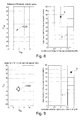
Figure 5 représente un électrocardiogramme de surface illustrant au cours de battements successifs diverses situations susceptibles d'être prises en compte par l'algorithme de détection de l'invention. - Les
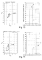
Figures 6 à 11 illustrent, pour les diverses situations consécutives illustrées sur l'électrocardiogramme de laFigure 5 , respectivement, à gauche le vectogramme correspondant obtenu, et à droite la position d'un descripteur évalué par l'algorithme de caractérisation par rapport à la frontière de décision entre capture et perte de capture.
- The
Figure 1 is a general view showing a bipolar probe implanted at the bottom of the ventricle. - The
Figure 2 illustrates the EGM signals obtained respectively on the ventricular bipolar and unipolar ventricular pathways of the configuration of theFigure 1 . - The
Figure 3 illustrates the cardiac loop obtained by combining the two signals of theFigure 2 . - The
Figure 4 illustrates the characterization parameters of a vectogram at a given point, with the curvature and the tangent vector at that point. - The
Figure 5 represents a surface electrocardiogram illustrating during successive beats various situations that may be taken into account by the detection algorithm of the invention. - The
Figures 6 to 11 illustrate, for the various consecutive situations illustrated on the electrocardiogram of theFigure 5 , respectively, on the left the corresponding vectogram obtained, and on the right the position of a descriptor evaluated by the characterization algorithm with respect to the decision boundary between capture and loss of capture.
On va maintenant décrire un exemple de réalisation du dispositif de l'invention.An embodiment of the device of the invention will now be described.
En ce qui concerne ses aspects logiciels, l'invention peut être mise en oeuvre par une programmation appropriée du logiciel de commande d'un stimulateur connu, par exemple de type stimulateur cardiaque, resynchroniseur et/ou défibrillateur, comprenant des moyens d'acquisition d'un signal fourni par des sondes endocavitaires et/ou un ou plusieurs capteurs implantés.With regard to its software aspects, the invention can be implemented by appropriate programming of the control software of a known pacemaker, for example of pacemaker, resynchronizer and / or defibrillator type, comprising means of acquisition of a signal provided by endocardial probes and / or one or more implanted sensors.
L'invention peut notamment être appliquée aux dispositifs implantables tels que ceux des familles Reply, Paradym, Ovatio, Esprit ou Rhapsody produits et commercialisés par ELA Médical, Montrouge, France (Sorin Group).The invention can in particular be applied to implantable devices such as those of the Reply, Paradym, Ovatio, Esprit or Rhapsody families produced and marketed by ELA Medical, Montrouge, France (Sorin Group).
Il s'agit de dispositifs à microprocesseur programmable comportant des circuits pour recevoir, mettre en forme et traiter des signaux électriques recueillis par des électrodes implantées, et délivrer des impulsions de stimulation à ces électrodes. Il est possible d'y transmettre par télémétrie des logiciels qui seront conservés en mémoire et exécutés pour mettre en oeuvre les fonctions de l'invention qui seront décrites ci-dessous. L'adaptation de ces appareils à la mise en oeuvre des fonctions de l'invention est à la portée de l'homme du métier, et elle ne sera pas décrite en détail. Comme cela a été indiqué plus haut, la technique d'analyse de l'invention consiste à détecter l'onde évoquée consécutive à la stimulation d'une cavité à partir de signaux d'électrogramme (EGM) recueillis sur deux voies distinctes et analysés en deux dimensions.These are programmable microprocessor devices having circuitry for receiving, shaping, and processing electrical signals collected by implanted electrodes, and providing pacing pulses to these electrodes. It is possible to transmit there by telemetry software which will be stored in memory and executed to implement the functions of the invention which will be described below. The adaptation of these devices to the implementation of the functions of the invention is within the abilities of those skilled in the art, and it will not be described in detail. As indicated above, the analysis technique of the invention consists in detecting the evoked wave following the stimulation of a cavity from electrogram (EGM) signals collected on two distinct channels and analyzed in two dimensions.
La
Cette configuration de type simple chambre a été choisie parce qu'elle est la plus simple pour exposer l'invention, mais elle n'est aucunement limitative. L'invention peut être appliquée de la même façon à la détection de la capture lors d'une stimulation de l'oreillette par une électrode appropriée, ou à la stimulation concomitante des deux ventricules droit et gauche dans le cas des dispositifs multisite, tout particulièrement les dispositifs de stimulation biventriculaire destinés à rétablir la synchronisation entre les deux ventricules. De façon générale, on parlera de "cavité", ce terme pouvant s'appliquer indifféremment à l'oreillette ou au ventricule, et aux cavités droites aussi bien qu'aux cavités gauches.
- La
Figure 2 illustre un exemple de tracés d'électrogrammes Vbip et Vuni observés respectivement sur la voie bipolaire ventriculaire (Fig. 2a ) et sur la voie unipolaire ventriculaire (Fig. 2b ) de la configuration de laFigure 1 . - L'étape suivante consiste, une fois ces signaux recueillis (dans le domaine temporel), à tracer l'un des signaux EGM en fonction de l'autre.
- La
Figure 3 illustre la caractéristique correspondante, dénommée "boucle cardiaque" ou "vectogramme" VGM (le vectogramme VGM devant être distingué du "vectocardiogramme" VCG, qui est obtenu à partir de signaux d'électrocardiogramme ECG externes, et non de signaux EGM qui sont des signaux intracardiaques).
- The
Figure 2 illustrates an example of Vbip and Vuni electrogram plots observed respectively on the ventricular bipolar pathway (Fig. 2a ) and on the unipolar ventricular pathway (Fig. 2b ) of the configuration of theFigure 1 . - The next step, once these signals are collected (in the time domain), is to trace one of the EGM signals according to the other.
- The
Figure 3 illustrates the corresponding characteristic, referred to as VGM "cardiac loop" or "vectogram" (the VGM vectogram to be distinguished from the "vectocardiogram" VCG, which is obtained from external ECG electrocardiogram signals, and not from EGM signals that are signals intracardiac).
Cette boucle VGM constitue donc une représentation d'un battement cardiaque complet dans un espace non temporel.This VGM loop is therefore a representation of a complete heartbeat in a non-temporal space.
Il n'est toutefois pas indispensable d'analyser la totalité du battement, l'analyse d'une fraction significative de ce battement (typiquement, celle centrée autour du complexe QRS) étant en général suffisante pour permettre la détection de l'onde évoquée.However, it is not essential to analyze the entire beat, the analysis of a significant fraction of this beat (typically centered around the QRS complex) being generally sufficient to allow detection of the evoked wave.
Plus précisément, le battement qui suit chaque stimulation est isolé par une fenêtre fixe, par exemple une fenêtre de largeur 100 ms (correspondant à 100 points pour une fréquence d'échantillonnage de 1000 Hz) décalée de 10 ms par rapport à l'instant de la stimulation. Cette valeur typique de 100 ms permet de bien isoler le complexe QRS pour en analyser la morphologie, sans trop inclure de bruit autour, bruit correspondant à la ligne de base après la fin du QRS. Les battements sont enregistrés simultanément sur la voie bipolaire ventriculaire (Vbip) et la voie unipolaire ventriculaire (Vuni). La fraction de chacun de ces battements comprise à l'intérieur de la fenêtre est alors représentée sous forme de vectogramme, considéré dans le plan constitué de la voie bipolaire en abscisse et de la voie unipolaire en ordonnée. On notera que dans ce cas le vectogramme correspondant n'est pas une boucle fermée, dans la mesure où il ne correspond qu'à une partie de la boucle cardiaque complète, à savoir le complexe QRS isolé à l'intérieur de la fenêtre.More precisely, the beat that follows each stimulation is isolated by a fixed window, for example a window of
L'invention consiste, essentiellement, à opérer le test de capture, c'est-à-dire la détection de l'onde évoquée, par une analyse du vectogramme, donc une analyse ne faisant pas intervenir le paramètre temporel.The invention consists, essentially, to perform the capture test, that is to say the detection of the evoked wave, by a vectogram analysis, so an analysis does not involve the temporal parameter.
Il s'agit de mesurer le niveau de capture (capture totale, fusion, absence de capture, ... ) de la cavité ou des cavités stimulées par le dispositif, notamment :
- pour vérifier que la thérapie a bien été délivrée sur les différents sites stimulés, notamment dans le cas d'une thérapie CRT où il est indispensable que les deux ventricules soient stimulés conjointement ;
- pour vérifier comment la thérapie a été délivrée, à des fins de "monitoring" (suivi du patient), notamment si l'on veut savoir si, par application de délais de stimulation optimisés sur des caractéristiques hémodynamiques du patient, cette optimisation produit une capture effective ou induit une situation de fusion ;
- pour adapter si nécessaire l'énergie de stimulation au minimum nécessaire, afin de réduire la consommation d'énergie de l'appareil et donc d'en augmenter la durée de vie ;
- pour adapter si besoin les intervalles de stimulation.
- to verify that the therapy has been delivered to the different stimulated sites, especially in the case of a CRT therapy where it is essential that the two ventricles are stimulated jointly;
- to verify how the therapy has been delivered, for purposes of "monitoring" (patient monitoring), especially whether one wants to know if, by applying optimized stimulation delays on hemodynamic characteristics of the patient, this optimization produces a capture effective or induces a situation of merger;
- to adapt, if necessary, the stimulation energy to the minimum necessary, in order to reduce the energy consumption of the device and thus to increase the life of the device;
- to adapt if necessary the stimulation intervals.
La mesure du niveau de capture par la technique de l'invention peut se faire cycle à cycle, avec ajustement (ou non) de l'énergie de stimulation ou des intervalles de stimulation (délai atrioventriculaire DAV et/ou délai interventriculaire DVV) en fonction des résultats. Ces réajustements éventuels peuvent aussi bien être réalisés à intervalles réguliers, par exemple toutes les six heures.Measurement of the level of capture by the technique of the invention can be done cycle to cycle, with adjustment (or not) of the stimulation energy or stimulation intervals (AV atrioventricular delay and / or DVV interventricular delay) depending results. These possible readjustments may also be made at regular intervals, for example every six hours.
On notera incidemment que, dans le cas des dispositifs multisite, le procédé de l'invention permet, comme on le verra, de tester la présence d'une capture sur tous les sites en même temps, à la différence des techniques actuelles qui imposent, pour s'assurer de la présence d'une capture sur chacun des sites stimulés, de faire des mesures de capture séparément sur chaque site de stimulation programmé.Incidentally, in the case of multisite devices, the method of the invention makes it possible, as will be seen, to test the presence of a capture on all the sites at the same time, unlike the current techniques which impose, to ensure that a capture is present at each of the stimulated sites, to make capture measurements separately at each programmed stimulation site.
L'analyse du vectogramme pour le test de capture peut être une analyse intrinsèque des propriétés de la boucle cardiaque, considérée en tant que telle sur le cycle à analyser.The vectogram analysis for the capture test may be an intrinsic analysis of the properties of the cardiac loop, considered as such on the cycle to be analyzed.
Mais de préférence cette analyse est une analyse comparative, consistant à rechercher une corrélation entre les caractéristiques du vectogramme du cycle à analyser d'une part, et les mêmes caractéristiques relevées sur un ou plusieurs cycles de référence dans des conditions parfaitement déterminées (capture, absence de capture, fusion, ... ) d'autre part.But preferably this analysis is a comparative analysis, consisting of looking for a correlation between the characteristics of the vectogram of the cycle to be analyzed on the one hand, and the same characteristics recorded on one or more reference cycles under perfectly determined conditions (capture, absence capture, fusion, ...) on the other hand.
La suite de la description se fera dans ce cadre d'une analyse comparative, mais sans caractère limitatif pour autant.The remainder of the description will be made in this context of a comparative analysis, but without being limiting in any way.
Dans une forme particulière de mise en oeuvre, qui n'a pas non plus de caractère limitatif, l'invention propose de réaliser la caractérisation du vectogramme par un descripteur basé sur le vecteur tangent
Il est notamment possible d'utiliser comme descripteur l'angle et/ou la norme de ce vecteur tangent
Le vecteur tangent
Un autre descripteur qu'il est possible d'utiliser est la courbure c (inverse du rayon de courbure r au point P du vectogramme VGM, et ceci pour les différents points échantillonnés successifs de ce vectogramme.Another descriptor that can be used is the curvature c (inverse of the radius of curvature r at the point P of the VGM vectogram, and this for the different successive sampled points of this vectogram.
Le vecteur tangent obtenu pour un cycle cardiaque à analyser est comparé au même vecteur pour des courbes de référence qui auront été obtenues au préalable, sur une durée identique, dans différentes conditions de référence telles que notamment :
- capture complète sur tous les sites stimulés, par utilisation d'une stimulation à haute énergie (quand on est donc sûr qu'il y aura toujours capture), ou par confirmation a posteriori de la capture par un médecin au vu des cycles enregistrés ;
- capture de certains sites seulement parmi les sites stimulés : une stimulation à haute énergie est délivrée aux sites sur lesquels on veut qu'il y ait capture, et une stimulation à zéro volt sur les autres ;
- perte de capture complète sur tous les sites stimulés, par stimulation à zéro volt de tous les sites.
- complete capture on all stimulated sites, using high energy stimulation (when one is sure that there will always be capture), or by post hoc confirmation of capture by a physician in view of recorded cycles;
- capturing only certain sites among the stimulated sites: high energy stimulation is delivered to the sites on which capture is desired, and zero volt stimulation to the others;
- Complete capture loss on all stimulated sites, by zero volt stimulation of all sites.
Tout ce qui ne ressemble pas à ces trois situations sera considéré comme une situation de fusion.Anything that does not look like these three situations will be considered a merger situation.
Des courbes de fusion de référence peuvent être créées également en adaptant des intervalles de stimulation par rapport aux événements électriques spontanés présents dans la cavité considérée.Reference melting curves can also be created by fitting stimulation intervals with respect to the spontaneous electrical events present in the cavity in question.
Les vectogrammes de référence sont obtenus soit manuellement, par un test déclenché par le praticien qui valide ensuite chaque type de référence, soit de façon automatique, pour les vectogrammes correspondant à une capture complète et aux pertes partielles ou complètes de capture. Dans ce dernier cas, le dispositif effectue régulièrement (par exemple toutes les quatre heures, toutes les semaines, ... ) des tests de stimulation à énergie élevée ou à zéro volt sur les différents sites, ce qui permet de mettre à jour les vectogrammes de référence.The reference vectograms are obtained either manually, by a test triggered by the practitioner who then validates each type of reference, or automatically, for the vectograms corresponding to a complete capture and the partial or complete losses of capture. In the latter case, the device performs regularly (for example every four hours, every week, ...) high-energy or zero-volt stimulation tests at the different sites, which allows the vectograms to be updated. reference.
On va maintenant expliquer la manière d'effectuer la comparaison entre le vectogramme du battement analysé et les vectogrammes de référence.We will now explain how to make a comparison between the vectogram of the beat analyzed and the reference vectograms.
Cette comparaison utilise un critère dérivé d'un ou plusieurs descripteurs permettant d'évaluer le degré de similarité des courbes : aire circonscrite par le vectogramme, angle ou norme du vecteur tangent, sens de parcours, analyse en composantes principales, ou tout autre critère permettant de décrire la morphologie et l'orientation de la courbe dans l'espace utilisé. En fonction du degré de similarité obtenu, le dispositif porte un diagnostic de capture totale, partielle ou nulle, le degré de similarité étant évalué par rapport à des seuils qui peuvent être linéaires ou non.This comparison uses a criterion derived from one or more descriptors to evaluate the degree of similarity of the curves: area circumscribed by the vectogram, angle or norm of the tangent vector, direction of travel, analysis in principal components, or any other criterion allowing to describe the morphology and the orientation of the curve in the space used. Depending on the degree of similarity obtained, the device carries a diagnosis total capture, partial or no, the degree of similarity being evaluated with respect to thresholds that may be linear or not.
De préférence, le descripteur est l'angle et/ou la norme du vecteur tangent
Dans le cas d'un dispositif biventriculaire par exemple, l'acquisition et la mémorisation préalable des vectogrammes de référence est exécutée par la séquence d'étapes suivante :
- acquisition du vectogramme de référence en capture biventriculaire ;
- délivrance sur huit cycles (par exemple) d'une stimulation biventriculaire à énergie maximale ;
- acquisition des EGM combinés pour chacun de ces huit cycles ;
- moyennage des huit EGM ;
- calcul des critères descriptifs correspondants ;
- stockage des critères descriptifs de la capture biventriculaire complète. Le même procédé est appliqué pour chaque type de vectogramme de référence : capture droite, capture gauche, perte complète de capture à droite et à gauche. Pour être sûr d'obtenir la capture, une énergie maximale est délivrée sur le site considéré ; pour au contraire être certain de ne pas obtenir de capture, la stimulation se fait en énergie nulle sur ce site.
- acquisition of the reference vectogram in biventricular capture;
- eight-cycle delivery (for example) of biventricular pacing at maximum energy;
- acquisition of the combined EGMs for each of these eight cycles;
- averaging of the eight EGMs;
- calculation of corresponding descriptive criteria;
- storage of descriptive criteria for complete biventricular capture. The same process is applied for each type of reference vectogram: right capture, left capture, complete capture loss right and left. To be sure of capturing, maximum energy is delivered to the site under consideration; on the contrary, to be certain of not obtaining a capture, the stimulation is done in zero energy on this site.
Une fois les électrogrammes de référence acquis et mémorisés, le test de capture sur un cycle cardiaque à analyser est exécuté de la manière suivante :
- stimulation ;
- acquisition du vectogramme sur l'événement courant ;
- calcul des critères descriptifs du vectogramme ainsi acquis ;
- comparaison des critères descriptifs du vectogramme courant par rapport au vectogramme de référence en capture biventriculaire. En cas de différence constatée, la comparaison est effectuée avec les autres vectogrammes de référence (capture droite seule, capture gauche seule), et si une différence est toujours présente on considérera qu'il y a perte de capture - avec dans ce dernier cas délivrance éventuelle d'une contre-stimulation de sécurité à énergie supérieure.
- stimulation;
- acquisition of the vectogram on the current event;
- calculation of the descriptive criteria of the vectogram thus acquired;
- comparison of the descriptive criteria of the current vectogram with respect to the reference vectogram in biventricular capture. In the event of a difference, the comparison is made with the other reference vectograms (right capture only, left capture only), and if a difference is still present, it will be considered that there is a loss of capture - with in the latter case delivery possible counter-stimulation safety higher energy.
La comparaison des vectogrammes du cycle à analyser avec le ou les vectogrammes de référence est effectuée par des algorithmes tels que ceux décrits dans le
Les
La
Les
Dans cet exemple, le critère retenu est celui d'un double descripteur X combinant (en abscisse) la valeur du coefficient de corrélation entre les normes des vecteurs tangents respectifs du vectogramme analysé et du vectogramme de référence, et d'autre part (en ordonnée) l'angle moyen entre ces mêmes vecteurs tangents respectifs. A partir de ces critères on a défini un domaine correspondant à la frontière F tel que si le double descripteur X se trouve à l'intérieur de ce domaine on considérera qu'il y a capture, et dans le cas contraire qu'il y a perte de capture. Le domaine est par exemple celui représenté par le rectangle correspondant aux critères : coefficient de corrélation > 0,5 et angle moyen < 70°.In this example, the criterion adopted is that of a double descriptor X combining (in abscissa) the value of the correlation coefficient between the norms of the respective tangent vectors of the analyzed vectogram and the reference vectogram, and on the other hand (on the ordinate ) the average angle between these same respective tangent vectors. From these criteria we have defined a domain corresponding to the boundary F such that if the double descriptor X is inside this domain we will consider that there is capture, and in the opposite case that there is loss of capture. The domain is for example that represented by the rectangle corresponding to the criteria: correlation coefficient> 0.5 and average angle <70 °.
Les
La
La
La distinction entre une perte de capture avérée et une situation de fusion peut être obtenue par exemple par application d'un critère portant sur l'aire circonscrite par le vectogramme, qui sera notablement supérieure dans le cas d'une fusion (
La
La
Le test de capture selon l'invention que l'on vient de décrire peut avantageusement être exploité dans le cadre d'une détermination du seuil de stimulation.The capture test according to the invention that has just been described can advantageously be used in the context of a determination of the stimulation threshold.
À cet effet, le dispositif applique à la cavité des impulsions de stimulation à énergie décroissante, et contrôle à chaque fois la présence ou non d'une onde évoquée par la méthode précédemment décrite. Si à une énergie donnée la capture est avérée, le dispositif considère que la stimulation est une stimulation efficace. L'énergie appliquée pour la stimulation suivante est réduite, typiquement d'un pas d'amplitude fixe, par exemple de 0,25 V. Dès que la capture est perdue, alors le dispositif considère que la stimulation est inefficace, et donc que le seuil de stimulation est supérieur à la dernière valeur appliquée. Dans ce dernier cas, une contre-stimulation de sécurité à amplitude maximale peut être appliquée afin de provoquer en tout état de cause une contraction de la cavité considérée.For this purpose, the device applies to the cavity pulses of stimulation with decreasing energy, and each time controls the presence or absence of of a wave evoked by the method described above. If at a given energy the capture is proven, the device considers that the stimulation is an effective stimulation. The energy applied for the next stimulation is reduced, typically of a fixed amplitude pitch, for example 0.25 V. As soon as the capture is lost, then the device considers that the stimulation is inefficient, and therefore that the pacing threshold is greater than the last applied value. In the latter case, a safety counter-stimulation at maximum amplitude can be applied in order to cause in any case a contraction of the cavity considered.
Le seuil de stimulation ainsi déterminé peut être conservé dans les mémoires de l'appareil, être transmis à un centre de recueil de données, ou encore utilisé par l'implant pour modifier l'amplitude de la stimulation. Pour d'autres détails sur les algorithmes d'ajustement de l'amplitude de stimulation à partir de tests de capture successifs, on pourra se référer notamment au
D'autres techniques que celles exposées ci-dessus peuvent être mises en oeuvre pour analyser le vectogramme et déterminer la présence ou non d'une capture.Other techniques than those described above can be implemented to analyze the vectogram and determine the presence or absence of a capture.
Une variante peut notamment mettre en oeuvre une analyse en composantes principales (analyse dite ACP) appliquée au vectogramme.A variant can in particular implement a principal component analysis (so-called PCA analysis) applied to the vectogram.
Cette analyse ACP est une technique en elle-même connue, qui permet de déduire l'axe électrique du coeur et fournir ainsi un indicateur de la direction générale que prend l'onde électrique lorsqu'elle se propage dans les ventricules. La voie de plus grande dynamique est celle qui présente la projection la plus grande, la direction correspondante étant dénommée "axe principal" ; cet axe peut être complété par deux autres axes dits "axes secondaires, perpendiculaires entre eux et à l'axe principal (dans le cas présent, on n'effectuera l'analyse qu'en deux dimensions, en ne considérant donc qu'un seul des axes secondaires).This ACP analysis is a technique in itself known, which allows to deduce the electrical axis of the heart and thus provide an indicator of the general direction that takes the electric wave when it spreads in the ventricles. The path of greatest dynamics is the one with the largest projection, the corresponding direction being called the "main axis"; this axis can be completed by two other axes called "secondary axes, perpendicular to each other and to the main axis (in the present case, the analysis will be carried out in two dimensions, thus considering only one secondary axes).
L'analyse en composantes principales ACP permet de définir la base orthonormée dans laquelle sera représenté le vectogramme Vuni = f(Vbip). Si l'on désigne par S1 et S2 les deux signaux sur les voies respectives Vbip et Vuni représentant un battement cardiaque, chaque signal est constitué de N points représentés dans la base des électrodes (Vbip, Vuni), les coordonnées du i ième point étant (S1(i), S2 (i)). Pour l'analyse en composantes principales, on fait l'approximation que ces N points forment une ellipse, ce qui permet de calculer les axes de cette ellipse qui forment la base ACP et la longueur de chacun d'eux. Ces deux valeurs permettent d'une part d'identifier la direction principale de l'ellipse (donc la direction d'étalement du vectogramme) et d'autre part de quantifier sa dimension et son aire. On recherchera donc les coordonnées de ces N points dans la base ACP (P1, P2), ce qui nécessitera le calcul de la matrice de passage de la base (Vbip, Vuni) à la base (P1, P2). The principal components analysis ACP allows to define the orthonormal base in which will be represented the vectogram Vuni = f (Vbip). If in S 1 and S 2 denotes the two signals on the respective channels and Vbip Vuni representing a cardiac beat, each signal consists of N points represented in the base electrodes (Vbip, uni), the coordinates of the ith point being (S 1 (i), S 2 ( i )). For the principal component analysis, we make the approximation that these N points form an ellipse, which makes it possible to calculate the axes of this ellipse which form the base ACP and the length of each one of them. These two values make it possible on the one hand to identify the main direction of the ellipse (hence the vectogram spreading direction) and on the other hand to quantify its size and its area. We will therefore look for the coordinates of these N points in the ACP base (P 1 , P 2 ), which will require the calculation of the transition matrix from the base (Vbip, Vuni) to the base (P 1 , P 2 ).
L'analyse en composantes principales permet notamment d'extraire les paramètres descripteurs suivants :
- l'axe principal, qui est le vecteur propre de la matrice de covariance associé à la plus grande valeur propre ;
- l'axe secondaire, qui est le vecteur propre de la matrice de covariance associé à la deuxième valeur propre ;
- les dimensions de ces axes, qui sont les deux valeurs propres de la matrice de covariance ;
- les angles que font les deux axes avec l'axe OX, à partir des calculs des sinus et des cosinus.
- the main axis, which is the eigenvector of the covariance matrix associated with the largest eigenvalue;
- the secondary axis, which is the eigenvector of the covariance matrix associated with the second eigenvalue;
- the dimensions of these axes, which are the two eigenvalues of the covariance matrix;
- the angles made by the two axes with the axis OX, from the sine and cosine calculations.
Pour pouvoir extraire à partir de l'ACP des descripteurs de la morphologie des vectogrammes, chaque signal est ensuite projeté sur sa propre base. Ceci permettra d'observer le signal unidimensionnel correspondant (qui sera donc un signal dans le domaine temporel) puis de comparer les formes afin de détecter la présence ou l'absence de l'onde évoquée, ou constater une indétermination du fait d'une situation de fusion.To be able to extract from the ACP descriptors of the morphology of the vectograms, each signal is then projected on its own base. This will make it possible to observe the corresponding one-dimensional signal (which will therefore be a signal in the time domain) and then to compare the shapes in order to detect the presence or the absence of the evoked wave, or to note an indeterminacy due to a situation. fusion.
Claims (15)
dispositif caractérisé en ce que les moyens de test de capture comprennent :
characterized in that the capture test means comprises:
Applications Claiming Priority (1)
| Application Number | Priority Date | Filing Date | Title |
|---|---|---|---|
| FR0958137 | 2009-11-18 |
Publications (2)
| Publication Number | Publication Date |
|---|---|
| EP2324885A1 true EP2324885A1 (en) | 2011-05-25 |
| EP2324885B1 EP2324885B1 (en) | 2018-10-24 |
Family
ID=42074550
Family Applications (1)
| Application Number | Title | Priority Date | Filing Date |
|---|---|---|---|
| EP10176951.1A Active EP2324885B1 (en) | 2009-11-18 | 2010-09-15 | Active medical device including means for capture testing through cardiac vectogram analysis |
Country Status (2)
| Country | Link |
|---|---|
| US (1) | US9014806B2 (en) |
| EP (1) | EP2324885B1 (en) |
Cited By (8)
| Publication number | Priority date | Publication date | Assignee | Title |
|---|---|---|---|---|
| EP2596832A1 (en) | 2011-11-22 | 2013-05-29 | Sorin CRM SAS | Implantable cardioverter-defibrillator medical device with dynamically adjustable ventricular sensing threshold |
| EP2623023A1 (en) | 2012-01-31 | 2013-08-07 | Sorin CRM SAS | Active implantable medical device including a means for diagnosing heart failure |
| EP2742971A1 (en) | 2012-12-14 | 2014-06-18 | Sorin CRM SAS | Active implantable medical device such as a pacemaker with capture testing by simplified analysis of a vector cardiogram |
| EP2742973A1 (en) | 2012-12-14 | 2014-06-18 | Sorin CRM SAS | Active implantable medical device such as a pacemaker with anodal stimulation detection by vector cardiogram analysis |
| EP3075413A1 (en) | 2015-04-02 | 2016-10-05 | Sorin CRM SAS | Implantable medical device for biventricular stimulation, including means for measuring intraventricular conduction time for diagnosis of heart decompensation |
| EP3081257A1 (en) | 2015-04-17 | 2016-10-19 | Sorin CRM SAS | Active implantable medical device for cardiac stimulation comprising means for detecting a remodelling or reverse remodelling phenomenon of the patient |
| EP3165160A1 (en) | 2015-11-05 | 2017-05-10 | Sorin CRM SAS | Active implantable medical device comprising means for detecting and quantifying fusion situations |
| WO2017102780A1 (en) * | 2015-12-18 | 2017-06-22 | Sorin Crm Sas | Active implantable medical device such as a cardiac resynchroniser with dynamic adaptation of atrioventricular delay depending on a detected and quantified degree of fusion |
Families Citing this family (2)
| Publication number | Priority date | Publication date | Assignee | Title |
|---|---|---|---|---|
| CN111836580A (en) | 2018-01-23 | 2020-10-27 | 程杰 | Accurate localization of cardiac arrhythmias using internal Electrocardiogram (ECG) signals sensed and stored by implantable devices |
| EP3760114B1 (en) * | 2019-07-05 | 2024-01-24 | Sorin CRM SAS | Subcutaneous implantable medical device for processing signals from a subcutaneous implantable medical device |
Citations (8)
| Publication number | Priority date | Publication date | Assignee | Title |
|---|---|---|---|---|
| WO1993002741A1 (en) | 1991-08-09 | 1993-02-18 | Ela Medical | Method and device for checking stimulation power in a pacemaker |
| EP1080744A1 (en) | 1999-09-03 | 2001-03-07 | Ela Medical | Implantable cardiac stimulator which automatically adjusts the level of stimulation pulses |
| EP1216722A1 (en) | 2000-12-12 | 2002-06-26 | Ela Medical | Active implantable medical device, in particular pacemaker, defibrillator and/or cardioverter having means for detecting fusion |
| EP1287849A1 (en) | 2001-08-28 | 2003-03-05 | Ela Medical | Active implantable medical device, in particular pacemaker, defibrillator, cardioverter or multisite device, with beat to beat adjusting means for the stimulation amplitude |
| US20050137638A1 (en) * | 2003-12-22 | 2005-06-23 | Yonce David J. | Automatic sensing vector selection for morphology-based capture verification |
| US20060253164A1 (en) * | 2005-05-09 | 2006-11-09 | Yi Zhang | Automatic capture verification using electrocardiograms sensed from multiple implanted electrodes |
| EP1995685A2 (en) * | 2007-05-21 | 2008-11-26 | BIOTRONIK CRM Patent AG | Medical device for monitoring biological signal |
| EP2105843A1 (en) | 2008-03-28 | 2009-09-30 | Ela Medical | Active medical device comprising perfected means for distinguishing between tachycardia with ventricular causes and tachycardia with supraventricular causes |
Family Cites Families (11)
| Publication number | Priority date | Publication date | Assignee | Title |
|---|---|---|---|---|
| US5179946A (en) * | 1989-12-28 | 1993-01-19 | Telectronics Pacing Systems, Inc. | Apparatus and method for arrhythmia detection by variations in the transcardiac impedance between defibrillation patches |
| US5275620A (en) * | 1990-05-21 | 1994-01-04 | Telectronics, N.V. | Implantable lead connectors and remote lead assembly |
| US5252090A (en) * | 1992-09-30 | 1993-10-12 | Telectronics Pacing Systems, Inc. | Self-locking implantable stimulating lead connector |
| FR2765486B1 (en) * | 1997-07-03 | 1999-10-01 | Ela Medical Sa | SYSTEM FOR THE MECHANICAL IMMOBILIZATION OF A PROBE CONNECTOR IN AN ACTIVE IMPLANTABLE MEDICAL DEVICE GENERATOR CONNECTOR, IN PARTICULAR FOR A HEART STIMULATOR, DEFIBRILLATOR AND / OR CARDIOVERTER |
| US6438409B1 (en) * | 1999-03-25 | 2002-08-20 | Medtronic, Inc. | Methods of characterizing ventricular operations and applications thereof |
| US20070191895A1 (en) * | 2001-04-20 | 2007-08-16 | Foreman Robert D | Activation of cardiac alpha receptors by spinal cord stimulation produces cardioprotection against ischemia, arrhythmias, and heart failure |
| US6760615B2 (en) * | 2001-10-31 | 2004-07-06 | Medtronic, Inc. | Method and apparatus for discriminating between tachyarrhythmias |
| US6766190B2 (en) * | 2001-10-31 | 2004-07-20 | Medtronic, Inc. | Method and apparatus for developing a vectorcardiograph in an implantable medical device |
| US7457664B2 (en) * | 2005-05-09 | 2008-11-25 | Cardiac Pacemakers, Inc. | Closed loop cardiac resynchronization therapy using cardiac activation sequence information |
| FR2906123A1 (en) * | 2006-09-25 | 2008-03-28 | Ela Medical Soc Par Actions Si | METHOD FOR RECONSTRUCTING A SURFACE ELECTROCARDIOGRAM FROM A ENDOCAVITARY ELECTROGRAM |
| FR2957512A1 (en) * | 2010-03-22 | 2011-09-23 | Sorin Crm Sas | ACTIVE MEDICAL DEVICE COMPRISING MEANS FOR DETECTING AND FILTERING ARTIFACTS BY ANALYZING THE HEART VECTOGRAM |
-
2010
- 2010-09-15 EP EP10176951.1A patent/EP2324885B1/en active Active
- 2010-11-18 US US12/949,653 patent/US9014806B2/en active Active
Patent Citations (9)
| Publication number | Priority date | Publication date | Assignee | Title |
|---|---|---|---|---|
| WO1993002741A1 (en) | 1991-08-09 | 1993-02-18 | Ela Medical | Method and device for checking stimulation power in a pacemaker |
| US5411533A (en) | 1991-08-09 | 1995-05-02 | Ela Medical S.A. | Method and device for checking stimulation power in a pacemaker |
| EP1080744A1 (en) | 1999-09-03 | 2001-03-07 | Ela Medical | Implantable cardiac stimulator which automatically adjusts the level of stimulation pulses |
| EP1216722A1 (en) | 2000-12-12 | 2002-06-26 | Ela Medical | Active implantable medical device, in particular pacemaker, defibrillator and/or cardioverter having means for detecting fusion |
| EP1287849A1 (en) | 2001-08-28 | 2003-03-05 | Ela Medical | Active implantable medical device, in particular pacemaker, defibrillator, cardioverter or multisite device, with beat to beat adjusting means for the stimulation amplitude |
| US20050137638A1 (en) * | 2003-12-22 | 2005-06-23 | Yonce David J. | Automatic sensing vector selection for morphology-based capture verification |
| US20060253164A1 (en) * | 2005-05-09 | 2006-11-09 | Yi Zhang | Automatic capture verification using electrocardiograms sensed from multiple implanted electrodes |
| EP1995685A2 (en) * | 2007-05-21 | 2008-11-26 | BIOTRONIK CRM Patent AG | Medical device for monitoring biological signal |
| EP2105843A1 (en) | 2008-03-28 | 2009-09-30 | Ela Medical | Active medical device comprising perfected means for distinguishing between tachycardia with ventricular causes and tachycardia with supraventricular causes |
Cited By (26)
| Publication number | Priority date | Publication date | Assignee | Title |
|---|---|---|---|---|
| US8694098B2 (en) | 2011-11-22 | 2014-04-08 | Sorin Crm Sas | Implantable defibrillator/cardioverter medical device with a dynamically adjustable threshold for ventricular detection |
| EP2596832A1 (en) | 2011-11-22 | 2013-05-29 | Sorin CRM SAS | Implantable cardioverter-defibrillator medical device with dynamically adjustable ventricular sensing threshold |
| US9668659B2 (en) | 2012-01-31 | 2017-06-06 | Sorin Crm Sas | Active implantable medical device for the diagnosis of heart failure |
| EP2623023A1 (en) | 2012-01-31 | 2013-08-07 | Sorin CRM SAS | Active implantable medical device including a means for diagnosing heart failure |
| US8938286B2 (en) | 2012-01-31 | 2015-01-20 | Sorin Crm Sas | Active implantable medical device comprising means for the diagnosis of heart failure |
| EP2742971A1 (en) | 2012-12-14 | 2014-06-18 | Sorin CRM SAS | Active implantable medical device such as a pacemaker with capture testing by simplified analysis of a vector cardiogram |
| EP2742973A1 (en) | 2012-12-14 | 2014-06-18 | Sorin CRM SAS | Active implantable medical device such as a pacemaker with anodal stimulation detection by vector cardiogram analysis |
| FR2999440A1 (en) * | 2012-12-14 | 2014-06-20 | Sorin Crm Sas | ACTIVE IMPLANTABLE MEDICAL DEVICE OF CARDIAC STIMULATOR TYPE HAVING ANODIC STIMULATION DETECTION BY VECTOGRAM ANALYSIS |
| US8874212B2 (en) | 2012-12-14 | 2014-10-28 | Sorin Crm S.A.S. | Active implantable medical device type such as a pacemaker with detection of anodal stimulation by analysis of a vectogram |
| US9014805B2 (en) | 2012-12-14 | 2015-04-21 | Sorin Crm S.A.S. | Active implantable medical device type such as a pacemaker with capture test by analysis of a vectogram |
| US10328269B2 (en) | 2015-04-02 | 2019-06-25 | Sorin Crm Sas | Active implantable medical device for the diagnosis of cardiac decompensation |
| US10022547B2 (en) | 2015-04-02 | 2018-07-17 | Sorin Crm Sas | Active implantable medical device for the diagnosis of cardiac decompensation |
| US11058881B2 (en) | 2015-04-02 | 2021-07-13 | Sorin Crm Sas | Active implantable medical device for the diagnosis of cardiac decompensation |
| FR3034319A1 (en) * | 2015-04-02 | 2016-10-07 | Sorin Crm Sas | ACTIVE IMPLANTABLE MEDICAL DEVICE WITH BIVENTRICULAR STIMULATION, COMPRISING MEANS FOR MEASURING INTERVENTRICULAR CONDUCTION TIME FOR DIAGNOSING CARDIAC DECOMPENSATION. |
| EP3075413A1 (en) | 2015-04-02 | 2016-10-05 | Sorin CRM SAS | Implantable medical device for biventricular stimulation, including means for measuring intraventricular conduction time for diagnosis of heart decompensation |
| US9757568B2 (en) | 2015-04-02 | 2017-09-12 | Sorin Crm Sas | Active implantable medical device for the diagnosis of cardiac decompensation |
| US10420945B2 (en) | 2015-04-17 | 2019-09-24 | Sorin Crm Sas | Active implantable medical device for detecting a remodeling or reverse remodeling phenomenon of the patient |
| US9757566B2 (en) | 2015-04-17 | 2017-09-12 | Sorin Crm Sas | Active implantable medical device for detecting a remodeling or reverse remodeling phenomenon of the patient |
| EP3081257A1 (en) | 2015-04-17 | 2016-10-19 | Sorin CRM SAS | Active implantable medical device for cardiac stimulation comprising means for detecting a remodelling or reverse remodelling phenomenon of the patient |
| US11198009B2 (en) | 2015-04-17 | 2021-12-14 | Sorin Crm Sas | Active implantable medical device for detecting a remodeling or reverse remodeling phenomenon of the patient |
| EP3517029A1 (en) | 2015-11-05 | 2019-07-31 | Sorin CRM SAS | Active implantable medical device comprising means for detecting and quantifying fusion situations |
| US10918876B2 (en) | 2015-11-05 | 2021-02-16 | Sorin Crm Sas | Active implantable medical device for detecting and quantifying fusion |
| EP3165160A1 (en) | 2015-11-05 | 2017-05-10 | Sorin CRM SAS | Active implantable medical device comprising means for detecting and quantifying fusion situations |
| US11865353B2 (en) | 2015-11-05 | 2024-01-09 | Sorin Crm Sas | Active implantable medical device for detecting and quantifying fusion |
| WO2017102780A1 (en) * | 2015-12-18 | 2017-06-22 | Sorin Crm Sas | Active implantable medical device such as a cardiac resynchroniser with dynamic adaptation of atrioventricular delay depending on a detected and quantified degree of fusion |
| US11027134B2 (en) | 2015-12-18 | 2021-06-08 | Sorin Crm Sas | Active implantable medical device such as a cardiac resynchroniser with dynamic adaptation of an atrioventricular delay depending on a detected and quantified degree of fusion |
Also Published As
| Publication number | Publication date |
|---|---|
| US9014806B2 (en) | 2015-04-21 |
| EP2324885B1 (en) | 2018-10-24 |
| US20110118804A1 (en) | 2011-05-19 |
Similar Documents
| Publication | Publication Date | Title |
|---|---|---|
| EP2324885B1 (en) | Active medical device including means for capture testing through cardiac vectogram analysis | |
| EP2412401B1 (en) | Active implantable medical device with means for testing ventricular capture by analysing an endocardiac acceleration signal | |
| EP2189182B1 (en) | Implantable active medical device comprising means for atrial capture testing | |
| EP2737925B1 (en) | Active implantable cardiac prosthesis with detection of atrial mechanical activity | |
| EP2105843B1 (en) | Active medical device comprising perfected means for distinguishing between tachycardia with ventricular causes and tachycardia with supraventricular causes | |
| EP1857142A1 (en) | Active implantable medical device for cardiac stimulation, resynchronisation, cardioversion and/or defibrillation, comprising means for detecting ventricular noise artefacts | |
| EP2368493B1 (en) | Active medical device including means for detecting and filtering artefacts by cardiac vector diagram analysis | |
| EP2742971B1 (en) | Active implantable medical device such as a pacemaker with capture testing by simplified analysis of a vector cardiogram | |
| FR2808102A1 (en) | SYSTEM AND METHOD FOR CLASSIFYING DETECTED EAR EVENTS IN A CARDIOSTIMULATION SYSTEM | |
| EP2712549B1 (en) | Device for assessing temporal ventricular dyssynchrony | |
| EP2471575B1 (en) | Active implantable medical device with auricular stimulation for the treatment of diastolic cardiac insufficiency | |
| FR2808212A1 (en) | Heart pacemaker has measurement and setting of noise threshold avoids false events | |
| EP2742973B1 (en) | Active implantable medical device such as a pacemaker with anodal stimulation detection by vector cardiogram analysis | |
| EP2311524A1 (en) | Medical implantable cardiac pacemaker with automatic interventricular and atrioventricular intervals optimization | |
| EP2495013B1 (en) | Assembly for searching for an optimal configuration of a bi-, tri- or multi-ventricular cardiac resynchronisation implant | |
| EP2508227A1 (en) | Implantable cardiac prosthesis for resynchronisation by bi-ventricular stimulation, including a reverse remodelling means | |
| EP3081257B1 (en) | Active implantable medical device for cardiac stimulation comprising means for detecting a remodelling or reverse remodelling phenomenon of the patient | |
| EP1857143A1 (en) | Active implantable medical device for cardiac stimulation, resynchronisation, cardioversion and/or defibrillation, comprising means for detecting catheter fractures | |
| EP2803385B1 (en) | Implantable heart re-timer with biventricular stimulation and detection of losses of capture and anode stimulations | |
| EP3831443B1 (en) | Implantable medical system for measuring a physiological parameter | |
| EP3075413B1 (en) | Implantable medical device for biventricular stimulation, including means for measuring intraventricular conduction time for diagnosis of heart decompensation | |
| EP3517029B1 (en) | Active implantable medical device comprising means for detecting and quantifying fusion situations | |
| EP3760114B1 (en) | Subcutaneous implantable medical device for processing signals from a subcutaneous implantable medical device | |
| EP2873436A1 (en) | Active implantable medical device with bi-auricular stimulation for treating cardiac insufficiency with HFpEF preserved ejection fraction | |
| EP3402397A1 (en) | Active implantable medical defibrillation device, including improved means for discriminating between external noise and probe breakage and for characterising tachyarrhythmias |
Legal Events
| Date | Code | Title | Description |
|---|---|---|---|
| PUAI | Public reference made under article 153(3) epc to a published international application that has entered the european phase |
Free format text: ORIGINAL CODE: 0009012 |
|
| AK | Designated contracting states |
Kind code of ref document: A1 Designated state(s): AL AT BE BG CH CY CZ DE DK EE ES FI FR GB GR HR HU IE IS IT LI LT LU LV MC MK MT NL NO PL PT RO SE SI SK SM TR |
|
| AX | Request for extension of the european patent |
Extension state: BA ME RS |
|
| 17P | Request for examination filed |
Effective date: 20110907 |
|
| STAA | Information on the status of an ep patent application or granted ep patent |
Free format text: STATUS: EXAMINATION IS IN PROGRESS |
|
| 17Q | First examination report despatched |
Effective date: 20170515 |
|
| GRAP | Despatch of communication of intention to grant a patent |
Free format text: ORIGINAL CODE: EPIDOSNIGR1 |
|
| STAA | Information on the status of an ep patent application or granted ep patent |
Free format text: STATUS: GRANT OF PATENT IS INTENDED |
|
| RIC1 | Information provided on ipc code assigned before grant |
Ipc: A61N 1/37 20060101ALI20171004BHEP Ipc: A61N 1/368 20060101AFI20171004BHEP |
|
| INTG | Intention to grant announced |
Effective date: 20171030 |
|
| RIN1 | Information on inventor provided before grant (corrected) |
Inventor name: HENRY, CHRISTINE Inventor name: MILPIED, PAOLA |
|
| GRAJ | Information related to disapproval of communication of intention to grant by the applicant or resumption of examination proceedings by the epo deleted |
Free format text: ORIGINAL CODE: EPIDOSDIGR1 |
|
| STAA | Information on the status of an ep patent application or granted ep patent |
Free format text: STATUS: EXAMINATION IS IN PROGRESS |
|
| INTC | Intention to grant announced (deleted) | ||
| GRAJ | Information related to disapproval of communication of intention to grant by the applicant or resumption of examination proceedings by the epo deleted |
Free format text: ORIGINAL CODE: EPIDOSDIGR1 |
|
| STAA | Information on the status of an ep patent application or granted ep patent |
Free format text: STATUS: GRANT OF PATENT IS INTENDED |
|
| GRAP | Despatch of communication of intention to grant a patent |
Free format text: ORIGINAL CODE: EPIDOSNIGR1 |
|
| RIC1 | Information provided on ipc code assigned before grant |
Ipc: A61N 1/37 20060101AFI20180423BHEP Ipc: A61N 1/368 20060101ALN20180423BHEP |
|
| INTG | Intention to grant announced |
Effective date: 20180511 |
|
| GRAS | Grant fee paid |
Free format text: ORIGINAL CODE: EPIDOSNIGR3 |
|
| GRAA | (expected) grant |
Free format text: ORIGINAL CODE: 0009210 |
|
| STAA | Information on the status of an ep patent application or granted ep patent |
Free format text: STATUS: THE PATENT HAS BEEN GRANTED |
|
| AK | Designated contracting states |
Kind code of ref document: B1 Designated state(s): AL AT BE BG CH CY CZ DE DK EE ES FI FR GB GR HR HU IE IS IT LI LT LU LV MC MK MT NL NO PL PT RO SE SI SK SM TR |
|
| REG | Reference to a national code |
Ref country code: GB Ref legal event code: FG4D Free format text: NOT ENGLISH |
|
| REG | Reference to a national code |
Ref country code: CH Ref legal event code: EP |
|
| REG | Reference to a national code |
Ref country code: IE Ref legal event code: FG4D Free format text: LANGUAGE OF EP DOCUMENT: FRENCH |
|
| REG | Reference to a national code |
Ref country code: AT Ref legal event code: REF Ref document number: 1055981 Country of ref document: AT Kind code of ref document: T Effective date: 20181115 |
|
| REG | Reference to a national code |
Ref country code: DE Ref legal event code: R096 Ref document number: 602010054540 Country of ref document: DE |
|
| REG | Reference to a national code |
Ref country code: NL Ref legal event code: MP Effective date: 20181024 |
|
| REG | Reference to a national code |
Ref country code: LT Ref legal event code: MG4D |
|
| REG | Reference to a national code |
Ref country code: AT Ref legal event code: MK05 Ref document number: 1055981 Country of ref document: AT Kind code of ref document: T Effective date: 20181024 |
|
| PG25 | Lapsed in a contracting state [announced via postgrant information from national office to epo] |
Ref country code: NL Free format text: LAPSE BECAUSE OF FAILURE TO SUBMIT A TRANSLATION OF THE DESCRIPTION OR TO PAY THE FEE WITHIN THE PRESCRIBED TIME-LIMIT Effective date: 20181024 |
|
| PG25 | Lapsed in a contracting state [announced via postgrant information from national office to epo] |
Ref country code: LV Free format text: LAPSE BECAUSE OF FAILURE TO SUBMIT A TRANSLATION OF THE DESCRIPTION OR TO PAY THE FEE WITHIN THE PRESCRIBED TIME-LIMIT Effective date: 20181024 Ref country code: AT Free format text: LAPSE BECAUSE OF FAILURE TO SUBMIT A TRANSLATION OF THE DESCRIPTION OR TO PAY THE FEE WITHIN THE PRESCRIBED TIME-LIMIT Effective date: 20181024 Ref country code: ES Free format text: LAPSE BECAUSE OF FAILURE TO SUBMIT A TRANSLATION OF THE DESCRIPTION OR TO PAY THE FEE WITHIN THE PRESCRIBED TIME-LIMIT Effective date: 20181024 Ref country code: LT Free format text: LAPSE BECAUSE OF FAILURE TO SUBMIT A TRANSLATION OF THE DESCRIPTION OR TO PAY THE FEE WITHIN THE PRESCRIBED TIME-LIMIT Effective date: 20181024 Ref country code: IS Free format text: LAPSE BECAUSE OF FAILURE TO SUBMIT A TRANSLATION OF THE DESCRIPTION OR TO PAY THE FEE WITHIN THE PRESCRIBED TIME-LIMIT Effective date: 20190224 Ref country code: NO Free format text: LAPSE BECAUSE OF FAILURE TO SUBMIT A TRANSLATION OF THE DESCRIPTION OR TO PAY THE FEE WITHIN THE PRESCRIBED TIME-LIMIT Effective date: 20190124 Ref country code: FI Free format text: LAPSE BECAUSE OF FAILURE TO SUBMIT A TRANSLATION OF THE DESCRIPTION OR TO PAY THE FEE WITHIN THE PRESCRIBED TIME-LIMIT Effective date: 20181024 Ref country code: BG Free format text: LAPSE BECAUSE OF FAILURE TO SUBMIT A TRANSLATION OF THE DESCRIPTION OR TO PAY THE FEE WITHIN THE PRESCRIBED TIME-LIMIT Effective date: 20190124 Ref country code: PL Free format text: LAPSE BECAUSE OF FAILURE TO SUBMIT A TRANSLATION OF THE DESCRIPTION OR TO PAY THE FEE WITHIN THE PRESCRIBED TIME-LIMIT Effective date: 20181024 Ref country code: HR Free format text: LAPSE BECAUSE OF FAILURE TO SUBMIT A TRANSLATION OF THE DESCRIPTION OR TO PAY THE FEE WITHIN THE PRESCRIBED TIME-LIMIT Effective date: 20181024 |
|
| PG25 | Lapsed in a contracting state [announced via postgrant information from national office to epo] |
Ref country code: SE Free format text: LAPSE BECAUSE OF FAILURE TO SUBMIT A TRANSLATION OF THE DESCRIPTION OR TO PAY THE FEE WITHIN THE PRESCRIBED TIME-LIMIT Effective date: 20181024 Ref country code: AL Free format text: LAPSE BECAUSE OF FAILURE TO SUBMIT A TRANSLATION OF THE DESCRIPTION OR TO PAY THE FEE WITHIN THE PRESCRIBED TIME-LIMIT Effective date: 20181024 Ref country code: PT Free format text: LAPSE BECAUSE OF FAILURE TO SUBMIT A TRANSLATION OF THE DESCRIPTION OR TO PAY THE FEE WITHIN THE PRESCRIBED TIME-LIMIT Effective date: 20190224 Ref country code: GR Free format text: LAPSE BECAUSE OF FAILURE TO SUBMIT A TRANSLATION OF THE DESCRIPTION OR TO PAY THE FEE WITHIN THE PRESCRIBED TIME-LIMIT Effective date: 20190125 |
|
| REG | Reference to a national code |
Ref country code: DE Ref legal event code: R097 Ref document number: 602010054540 Country of ref document: DE |
|
| PG25 | Lapsed in a contracting state [announced via postgrant information from national office to epo] |
Ref country code: DK Free format text: LAPSE BECAUSE OF FAILURE TO SUBMIT A TRANSLATION OF THE DESCRIPTION OR TO PAY THE FEE WITHIN THE PRESCRIBED TIME-LIMIT Effective date: 20181024 Ref country code: CZ Free format text: LAPSE BECAUSE OF FAILURE TO SUBMIT A TRANSLATION OF THE DESCRIPTION OR TO PAY THE FEE WITHIN THE PRESCRIBED TIME-LIMIT Effective date: 20181024 |
|
| PG25 | Lapsed in a contracting state [announced via postgrant information from national office to epo] |
Ref country code: RO Free format text: LAPSE BECAUSE OF FAILURE TO SUBMIT A TRANSLATION OF THE DESCRIPTION OR TO PAY THE FEE WITHIN THE PRESCRIBED TIME-LIMIT Effective date: 20181024 Ref country code: EE Free format text: LAPSE BECAUSE OF FAILURE TO SUBMIT A TRANSLATION OF THE DESCRIPTION OR TO PAY THE FEE WITHIN THE PRESCRIBED TIME-LIMIT Effective date: 20181024 Ref country code: SM Free format text: LAPSE BECAUSE OF FAILURE TO SUBMIT A TRANSLATION OF THE DESCRIPTION OR TO PAY THE FEE WITHIN THE PRESCRIBED TIME-LIMIT Effective date: 20181024 Ref country code: SK Free format text: LAPSE BECAUSE OF FAILURE TO SUBMIT A TRANSLATION OF THE DESCRIPTION OR TO PAY THE FEE WITHIN THE PRESCRIBED TIME-LIMIT Effective date: 20181024 |
|
| PLBE | No opposition filed within time limit |
Free format text: ORIGINAL CODE: 0009261 |
|
| STAA | Information on the status of an ep patent application or granted ep patent |
Free format text: STATUS: NO OPPOSITION FILED WITHIN TIME LIMIT |
|
| 26N | No opposition filed |
Effective date: 20190725 |
|
| PG25 | Lapsed in a contracting state [announced via postgrant information from national office to epo] |
Ref country code: SI Free format text: LAPSE BECAUSE OF FAILURE TO SUBMIT A TRANSLATION OF THE DESCRIPTION OR TO PAY THE FEE WITHIN THE PRESCRIBED TIME-LIMIT Effective date: 20181024 |
|
| PG25 | Lapsed in a contracting state [announced via postgrant information from national office to epo] |
Ref country code: TR Free format text: LAPSE BECAUSE OF FAILURE TO SUBMIT A TRANSLATION OF THE DESCRIPTION OR TO PAY THE FEE WITHIN THE PRESCRIBED TIME-LIMIT Effective date: 20181024 |
|
| PG25 | Lapsed in a contracting state [announced via postgrant information from national office to epo] |
Ref country code: MC Free format text: LAPSE BECAUSE OF FAILURE TO SUBMIT A TRANSLATION OF THE DESCRIPTION OR TO PAY THE FEE WITHIN THE PRESCRIBED TIME-LIMIT Effective date: 20181024 |
|
| REG | Reference to a national code |
Ref country code: CH Ref legal event code: PL |
|
| PG25 | Lapsed in a contracting state [announced via postgrant information from national office to epo] |
Ref country code: IE Free format text: LAPSE BECAUSE OF NON-PAYMENT OF DUE FEES Effective date: 20190915 Ref country code: LU Free format text: LAPSE BECAUSE OF NON-PAYMENT OF DUE FEES Effective date: 20190915 Ref country code: LI Free format text: LAPSE BECAUSE OF NON-PAYMENT OF DUE FEES Effective date: 20190930 Ref country code: CH Free format text: LAPSE BECAUSE OF NON-PAYMENT OF DUE FEES Effective date: 20190930 |
|
| REG | Reference to a national code |
Ref country code: BE Ref legal event code: MM Effective date: 20190930 |
|
| PG25 | Lapsed in a contracting state [announced via postgrant information from national office to epo] |
Ref country code: BE Free format text: LAPSE BECAUSE OF NON-PAYMENT OF DUE FEES Effective date: 20190930 |
|
| PG25 | Lapsed in a contracting state [announced via postgrant information from national office to epo] |
Ref country code: CY Free format text: LAPSE BECAUSE OF FAILURE TO SUBMIT A TRANSLATION OF THE DESCRIPTION OR TO PAY THE FEE WITHIN THE PRESCRIBED TIME-LIMIT Effective date: 20181024 |
|
| PG25 | Lapsed in a contracting state [announced via postgrant information from national office to epo] |
Ref country code: MT Free format text: LAPSE BECAUSE OF FAILURE TO SUBMIT A TRANSLATION OF THE DESCRIPTION OR TO PAY THE FEE WITHIN THE PRESCRIBED TIME-LIMIT Effective date: 20181024 Ref country code: HU Free format text: LAPSE BECAUSE OF FAILURE TO SUBMIT A TRANSLATION OF THE DESCRIPTION OR TO PAY THE FEE WITHIN THE PRESCRIBED TIME-LIMIT; INVALID AB INITIO Effective date: 20100915 |
|
| REG | Reference to a national code |
Ref country code: DE Ref legal event code: R082 Ref document number: 602010054540 Country of ref document: DE Representative=s name: PAGE, WHITE & FARRER GERMANY LLP, DE |
|
| PG25 | Lapsed in a contracting state [announced via postgrant information from national office to epo] |
Ref country code: MK Free format text: LAPSE BECAUSE OF FAILURE TO SUBMIT A TRANSLATION OF THE DESCRIPTION OR TO PAY THE FEE WITHIN THE PRESCRIBED TIME-LIMIT Effective date: 20181024 |
|
| P01 | Opt-out of the competence of the unified patent court (upc) registered |
Effective date: 20230714 |
|
| PGFP | Annual fee paid to national office [announced via postgrant information from national office to epo] |
Ref country code: IT Payment date: 20230911 Year of fee payment: 14 Ref country code: GB Payment date: 20230920 Year of fee payment: 14 |
|
| PGFP | Annual fee paid to national office [announced via postgrant information from national office to epo] |
Ref country code: FR Payment date: 20230927 Year of fee payment: 14 Ref country code: DE Payment date: 20230911 Year of fee payment: 14 |