EP2322901A2 - Method for improving position and orientation measurement data - Google Patents
Method for improving position and orientation measurement data Download PDFInfo
- Publication number
- EP2322901A2 EP2322901A2 EP10450162A EP10450162A EP2322901A2 EP 2322901 A2 EP2322901 A2 EP 2322901A2 EP 10450162 A EP10450162 A EP 10450162A EP 10450162 A EP10450162 A EP 10450162A EP 2322901 A2 EP2322901 A2 EP 2322901A2
- Authority
- EP
- European Patent Office
- Prior art keywords
- positions
- pos
- imu
- images
- gnss
- Prior art date
- Legal status (The legal status is an assumption and is not a legal conclusion. Google has not performed a legal analysis and makes no representation as to the accuracy of the status listed.)
- Withdrawn
Links
Images

Classifications
-
- G—PHYSICS
- G01—MEASURING; TESTING
- G01C—MEASURING DISTANCES, LEVELS OR BEARINGS; SURVEYING; NAVIGATION; GYROSCOPIC INSTRUMENTS; PHOTOGRAMMETRY OR VIDEOGRAMMETRY
- G01C15/00—Surveying instruments or accessories not provided for in groups G01C1/00 - G01C13/00
-
- G—PHYSICS
- G01—MEASURING; TESTING
- G01B—MEASURING LENGTH, THICKNESS OR SIMILAR LINEAR DIMENSIONS; MEASURING ANGLES; MEASURING AREAS; MEASURING IRREGULARITIES OF SURFACES OR CONTOURS
- G01B11/00—Measuring arrangements characterised by the use of optical techniques
- G01B11/02—Measuring arrangements characterised by the use of optical techniques for measuring length, width or thickness
- G01B11/03—Measuring arrangements characterised by the use of optical techniques for measuring length, width or thickness by measuring coordinates of points
-
- G—PHYSICS
- G01—MEASURING; TESTING
- G01S—RADIO DIRECTION-FINDING; RADIO NAVIGATION; DETERMINING DISTANCE OR VELOCITY BY USE OF RADIO WAVES; LOCATING OR PRESENCE-DETECTING BY USE OF THE REFLECTION OR RERADIATION OF RADIO WAVES; ANALOGOUS ARRANGEMENTS USING OTHER WAVES
- G01S19/00—Satellite radio beacon positioning systems; Determining position, velocity or attitude using signals transmitted by such systems
- G01S19/01—Satellite radio beacon positioning systems transmitting time-stamped messages, e.g. GPS [Global Positioning System], GLONASS [Global Orbiting Navigation Satellite System] or GALILEO
- G01S19/13—Receivers
- G01S19/14—Receivers specially adapted for specific applications
-
- G—PHYSICS
- G01—MEASURING; TESTING
- G01S—RADIO DIRECTION-FINDING; RADIO NAVIGATION; DETERMINING DISTANCE OR VELOCITY BY USE OF RADIO WAVES; LOCATING OR PRESENCE-DETECTING BY USE OF THE REFLECTION OR RERADIATION OF RADIO WAVES; ANALOGOUS ARRANGEMENTS USING OTHER WAVES
- G01S19/00—Satellite radio beacon positioning systems; Determining position, velocity or attitude using signals transmitted by such systems
- G01S19/38—Determining a navigation solution using signals transmitted by a satellite radio beacon positioning system
- G01S19/39—Determining a navigation solution using signals transmitted by a satellite radio beacon positioning system the satellite radio beacon positioning system transmitting time-stamped messages, e.g. GPS [Global Positioning System], GLONASS [Global Orbiting Navigation Satellite System] or GALILEO
- G01S19/42—Determining position
- G01S19/48—Determining position by combining or switching between position solutions derived from the satellite radio beacon positioning system and position solutions derived from a further system
- G01S19/49—Determining position by combining or switching between position solutions derived from the satellite radio beacon positioning system and position solutions derived from a further system whereby the further system is an inertial position system, e.g. loosely-coupled
-
- G—PHYSICS
- G01—MEASURING; TESTING
- G01S—RADIO DIRECTION-FINDING; RADIO NAVIGATION; DETERMINING DISTANCE OR VELOCITY BY USE OF RADIO WAVES; LOCATING OR PRESENCE-DETECTING BY USE OF THE REFLECTION OR RERADIATION OF RADIO WAVES; ANALOGOUS ARRANGEMENTS USING OTHER WAVES
- G01S19/00—Satellite radio beacon positioning systems; Determining position, velocity or attitude using signals transmitted by such systems
- G01S19/38—Determining a navigation solution using signals transmitted by a satellite radio beacon positioning system
- G01S19/39—Determining a navigation solution using signals transmitted by a satellite radio beacon positioning system the satellite radio beacon positioning system transmitting time-stamped messages, e.g. GPS [Global Positioning System], GLONASS [Global Orbiting Navigation Satellite System] or GALILEO
- G01S19/42—Determining position
- G01S19/51—Relative positioning
-
- G—PHYSICS
- G01—MEASURING; TESTING
- G01S—RADIO DIRECTION-FINDING; RADIO NAVIGATION; DETERMINING DISTANCE OR VELOCITY BY USE OF RADIO WAVES; LOCATING OR PRESENCE-DETECTING BY USE OF THE REFLECTION OR RERADIATION OF RADIO WAVES; ANALOGOUS ARRANGEMENTS USING OTHER WAVES
- G01S19/00—Satellite radio beacon positioning systems; Determining position, velocity or attitude using signals transmitted by such systems
- G01S19/38—Determining a navigation solution using signals transmitted by a satellite radio beacon positioning system
- G01S19/39—Determining a navigation solution using signals transmitted by a satellite radio beacon positioning system the satellite radio beacon positioning system transmitting time-stamped messages, e.g. GPS [Global Positioning System], GLONASS [Global Orbiting Navigation Satellite System] or GALILEO
- G01S19/53—Determining attitude
-
- G—PHYSICS
- G01—MEASURING; TESTING
- G01S—RADIO DIRECTION-FINDING; RADIO NAVIGATION; DETERMINING DISTANCE OR VELOCITY BY USE OF RADIO WAVES; LOCATING OR PRESENCE-DETECTING BY USE OF THE REFLECTION OR RERADIATION OF RADIO WAVES; ANALOGOUS ARRANGEMENTS USING OTHER WAVES
- G01S17/00—Systems using the reflection or reradiation of electromagnetic waves other than radio waves, e.g. lidar systems
- G01S17/88—Lidar systems specially adapted for specific applications
- G01S17/89—Lidar systems specially adapted for specific applications for mapping or imaging
Definitions
- the present invention relates to a method for improving the position and attitude measurement data measured by an IMU / GNSS subsystem of a mobile laser scanning system.
- MLS systems Mobile laser scanning systems
- the topography of the landscape is captured by a moving land, air or water vehicle, which carries the MLS system.
- the scan data of the MLS system is typically a 3D image (a "point cloud") of the laser scanned surrounding area. It is crucial for the imaging accuracy of the MLS system that its trajectory and orientation, measured as a sequence of position and attitude measurement data, also called “trajectory”, are determined exactly. Already angular deviations of a few milligrams can lead to significant measurement and thus aberrations of the MLS system over the long distances to be traversed by the laser scanning beams.
- an inertial measurement unit (IMU) carried by it is often used in conjunction with a global navigation satellite system (GNSS) .
- GNSS global navigation satellite system
- the IMU / GNSS subsystem continuously determines the positions and locations and thus the trajectory of the MLS system in a world coordinate calibratable reference system so that the scan data of the MLS system can be referenced.
- IMU / GNSS subsystems In practice, however, the measurement accuracy of IMU / GNSS subsystems often leaves much to be desired.
- the causes may be manifold, such as shadowing the line-of-sight (LOS) from the GNSS receiver to the satellites through buildings or vegetation, multipath propagation of the GNSS signals, or complete loss of the GNSS signals Driving through tunnels.
- LOS line-of-sight
- IMU subsystems Driving through tunnels.
- errors not exactly genordete or horizontal IMU subsystems cause errors, as well as the long-term drift of IMU subsystems. All these errors manifest themselves directly in the scan data generated by the MLS system, eg 3D images, as distortions, edge jumps etc. of the imaged environment.
- the 3D images generated by the MLS system are used directly to improve the trajectory on which they are based.
- the invention is based on the finding that by twice scanning one and the same surrounding area and detecting the spatial position change of an object in the two 3D images thus generated on the measurement errors of the positions and / or locations, of which the two 3D images are scanned out were, can be closed.
- the correction of the position measurement error is particularly advantageous because they lead over the long paths to be traveled by the laser scanning beams to particularly significant measurement errors.
- the positions measured by the IMU / GNSS subsystem can also be corrected by those position measurement errors resulting from said comparison of the spatial positions of the object detected in the two 3D images.
- spatial position of an object used here encompasses both its position and position (orientation) in the image space of the 3D image.
- the method is progressively repeated for a multiplicity of successive positions and positions forming a trajectory, respectively applied to two successive positions and positions in the trajectory in order to improve the measurement accuracy of the trajectory.
- the image processing to be performed for object detection can be accelerated if, according to a further feature of the invention, the position measurement error is determined from the solid angle difference of a selected spatial axis of the object, adjusted for the differences between the first and second positions and positions.
- an area detected in the surrounding area is selected as the object and its surface normal as said spatial axis, whereby implementations with particularly short computing times can be achieved.
- the two 3D images could be generated with the help of an MLS system with only a single laser scanner, which is passed twice in the same area of the environment.
- the two 3D images are generated by means of an MLS system comprising two laser scanners, which scans the two laser scanners past the same surrounding area at a short time interval.
- the two laser scanners can be arranged in the MLS system preferably with a predetermined distance and predetermined relative position to each other and / or each laser beams in emit a scanning plane and are arranged with mutually inclined scanning planes.
- the latter laser scanners can, as is known to those skilled in the art, in particular also detect undercuts in the surrounding area.
- camera images of the surrounding area may be made from the first and second positions and locations which are assisted in detecting the object in the 3D images.
- significant points of an object can be detected in particular from a joint evaluation of the camera images and the 3D images in order to detect this in the 3D images.
- position and location are determined by data fusion from raw data, with raw data from time-of-flight measurements taken to GNSS satellites, and gyroscope and linear accelerator accelerometer accelerations from an IMU to raw data.
- the position preferably refers to a geocentric Cartesian coordinate system (ECEF, Earth Centered - Earth Fixed) 1.
- ECEF Earth Centered - Earth Fixed
- the position becomes relative to a local horizontal system (Navigation coordinate system) interpreted.
- An often used navigation coordinate system is described in the aviation standard ARINC 705, in which the north direction (x-axis) and the east direction (y-axis) lie in the tangential plane to the Erdellipsoid and the vertical axis (z-axis) points parallel to the gravitational acceleration in the direction of the earth's core.
- MLS systems usually consist of an IMU / GNSS subsystem, laser scanners, digital cameras and any other sensors.
- the present considerations are based on an MLS system consisting of an IMU / GNSS subsystem as well as at least two laser scanners whose detection areas do not coincide spatially at one time, but nevertheless capture the same objects to a great extent by the movement of the system.
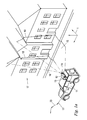
- Such a system is in Fig. 1 shown as an example.
- Fig. 1 is mounted on a means of transport 11, such as an off-road vehicle, an MLS system 12.
- the conveyor 11 may be any other land, air or water vehicle, both motorized and powered muscle, such as a truck, a rail vehicle, a boat, a lore, a trolley or in the simplest case even just a stretcher.
- the MLS system 12 comprises two 360.degree. -2D laser scanners 13, 14, as produced, for example, under the trade name VQ® with the type designation 250 from Riegl Laser Measurement Systems GmbH in Horn, Austria.
- Each of the 360 ° -2D laser scanners 13, 14 transmits a laser beam fan 15, 16 over a full circumferential range of 360 ° (see Fig. 1b ) to a surrounding area 17 in order to ever detect a 2D profile 18, 19 of the environment 17.
- a 3D image 20, 21 see FIG. 4 of a plurality of successive 2D profiles 18, 19 of each laser scanner 13, 14 (see FIG Fig. 2 and 4 ) the environment 17 created.
- the MLS system 12 further includes an IMU / GNSS subsystem 22 comprised of an inertial measurement subsystem (IMU) and a satellite navigation subsystem (GNSS) for continuously monitoring the position and attitude (orientation) of the MLS system 12, ie to determine its trajectory and orientation, the so-called trajectory 23, in the world coordinate system 1.
- IMU inertial measurement subsystem
- GNSS satellite navigation subsystem
- the trajectory 23 determined by the IMU / GNSS subsystem 22 is taken into account during the laser scanning - or even later in a later offline evaluation - around the 2D profiles 18, 19 or 3D detected by the MLS system 12 Figures 20, 21 relate to the trajectory 23 and so as correctly aligned 3D images 20, 21 of the environment 17 in a world coordinate system 1 build.
- the two laser scanners 13, 14 are arranged for this purpose in the MLS system 12 at a mutual distance and / or inclined to each other, so that they scan a surrounding area 17 at short distances successively during the movement of the conveyor 11.
- two 3D images 20, 21 of one and the same surrounding area 17 are produced, albeit from different positions and locations (orientations, viewing angles).
- the preparation of the IMU / GNSS data taking into account the GNSS reference station data supplies the position and position information of the IMU / GNSS system over time.
- the so-called trajectory with known orientation of the laser scanner with respect to the IMU / GNSS system
- the laser scan data can be converted into an ECEF system or a projection ("geo-referencing").
- the result is a so-called point cloud of the laser scan data in the ECEF system.
- the point cloud at this point in time has position errors, ie scanned objects appear twice in the point cloud because the exact mounting position of the two scanners with respect to the IMU position information has not yet been determined.
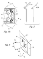
- the determination of the so-called "system calibration" is now based on this point cloud, and as soon as the correction values were taken into account in the geo-referencing again, the point cloud is free from positional errors - all scanned objects appear only once and thus show an image of the actual spatial Conditions ( Fig. 2 ).
- Fig. 3 shows the MLS system 12 with two laser scanners 13, 14 in two different positions, POS 1 , and POS 2 .
- the MLS system moves along the actual trajectory 23 or TR (dot-dashed line). It is assumed that the orientation of the laser scanner in MLS's own coordinate system ("Body Coordinate System") is known by system calibration and is fixed in time.
- the x-coordinate of the body coordinate system is indicated by the vectors X BODY1 and X BODY2 (solid arrows) in the two positions. These vectors enclose the heading angles ⁇ 1 and ⁇ 2 with the actual north direction.
- the spatial point P is detected by the first 2D laser scanner 13 with the measuring compartment 15 (indicated by the beam SC1).
- the measuring beam of the second 2D laser scanner 14 detects the same spatial point P.
- the geo referencing of the laser scan data returns the measured values for the point in space P were obtained, come to lie at different spatial positions P 1 * and P 2 *.
- the course angles ⁇ 1 and ⁇ 2 can be determined from known positions. If the positions are subject to measuring errors, they will also be included in the determination of the course angles. However, if the base length is sufficiently long (distance between positions POS 1 and POS 2 ), the angle measurement errors due to the faulty position measurement will remain small.
- support values can be determined for an improved calculation of the trajectory, in particular for the resolution of phase ambiguities with lower GNSS raw data quality, eg in the case of so-called "GNSS outages" in densely built-up area.
- a support of the position information can also be obtained via image information, if optionally at least one camera, which is fixed to the body coordinate system and connected in a known manner, at the positions POS 1 and POS 2 images of supplies the same objects.
- image information if optionally at least one camera, which is fixed to the body coordinate system and connected in a known manner, at the positions POS 1 and POS 2 images of supplies the same objects.
- nodes identifiable significant points
- the object 43 is a flat region of a building present in the surrounding area 17.
- the respective spatial position of the object 43 in the 3D images 20, 21 is determined, preferably using a selected, e.g. Preferably, an area is selected as the object 43, and the location (orientation) of the surface normals 41, 42 in conjunction with the locations (positions) of the object 43 in the 3D images 20, 21 give its respective spatial position at.
- the solid angle difference 44 and the position difference of the object 43 in the 3D images 20, 21 can then be in knowledge of the first and second positions POS 1 , POS 2 and layers ⁇ 1 and ⁇ 2 or ⁇ 1 * and ⁇ 2 * to the position measurement error ⁇ 1 - ⁇ 1 *, ⁇ 2 - ⁇ 2 * etc. of the trajectory 23, as shown by Fig. 3 explained.
- the previously provisionally determined position estimates POS 1 and POS 2 of the trajectory 23 can also be corrected on the basis of the position measurement errors which result from this comparison.
- amplitude information or information about the reflectance of the detected objects can also be used to determine the support information.
- the point cloud of the laser scanner can be automatically colored.
- this point cloud with color information further possibilities for the detection of correspondences are open.
Abstract
Description
Die vorliegende Erfindung betrifft ein Verfahren zum Verbessern der Positions- und Lagemessdaten, die von einem IMU/GNSS-Subsystem eines mobilen Laserscanning-Systems gemessen werden.The present invention relates to a method for improving the position and attitude measurement data measured by an IMU / GNSS subsystem of a mobile laser scanning system.
Mobile Laserscanning-Systeme (MLS-Systeme) werden in zunehmendem Maße zur terrestrischen Landvermessung eingesetzt. Dabei wird die Topografie der Landschaft von einem bewegten Land-, Luft- oder Wasserfahrzeug aus erfasst, welches das MLS-System trägt. Die Scandaten des MLS-Systems sind in der Regel ein 3D-Abbild (eine "Punktewolke") des laserabgetasteten Umgebungsbereichs. Für die Abbildungsgenauigkeit des MLS-Systems ist es von entscheidender Bedeutung, dass seine Bewegungsbahn und -orientierung, gemessen als Abfolge von Postions- und Lagemessdaten, auch "Trajektorie" genannt, exakt bestimmt werden. Bereits Winkelabweichungen von wenigen Milligrad können über die von den Laserabtaststrahlen zurückzulegenden langen Wege zu signifikanten Mess- und damit Abbildungsfehlern des MLS-Systems führen.Mobile laser scanning systems (MLS systems) are increasingly used for terrestrial land surveying. The topography of the landscape is captured by a moving land, air or water vehicle, which carries the MLS system. The scan data of the MLS system is typically a 3D image (a "point cloud") of the laser scanned surrounding area. It is crucial for the imaging accuracy of the MLS system that its trajectory and orientation, measured as a sequence of position and attitude measurement data, also called "trajectory", are determined exactly. Already angular deviations of a few milligrams can lead to significant measurement and thus aberrations of the MLS system over the long distances to be traversed by the laser scanning beams.
Zur Messung der Position und Lage (der Trajektorie) des MLS-Systems wird häufig ein von diesem mitgeführtes Trägheitsmess-Subsystem ("inertial measurement unit", IMU) in Verbindung mit einem Satellitennavigations-Subsystem ("global navigation satellite system", GNSS) verwendet. Das IMU/GNSS-Subsystem ermittelt fortlaufend die Positionen und Lagen und damit die Trajektorie des MLS-Systems in einem gegenüber Weltkoordinaten kalibrierbaren Referenzsystem, so dass die Scandaten des MLS-Systems darauf bezogen werden können.To measure the position and attitude (trajectory) of the MLS system, an inertial measurement unit (IMU) carried by it is often used in conjunction with a global navigation satellite system (GNSS) , The IMU / GNSS subsystem continuously determines the positions and locations and thus the trajectory of the MLS system in a world coordinate calibratable reference system so that the scan data of the MLS system can be referenced.
In der Praxis zeigt sich jedoch, dass die Messgenauigkeit von IMU/GNSS-Subsystemen häufig zu wünschen übrig lässt. Die Ursachen können mannigfaltig sein, beispielsweise Abschattungen der Line-of-Sight (LOS) vom GNSS-Empfänger zu den Satelliten durch Gebäude oder Vegetation, Mehrwegeausbreitung der GNSS-Signale, oder vollständiger Verlust der GNSS-Signale beim Durchfahren von Tunnels. Auch nicht exakt genordete oder horizontierte IMU-Subsysteme verursachen Fehler, ebenso wie die Langzeitdrift von IMU-Subsystemen. Alle diese Fehler zeigen sich unmittelbar in den vom MLS-System erzeugten Scandaten, z.B. 3D-Abbildern, als Verzerrungen, Kantensprünge usw. der abgebildeten Umgebung.In practice, however, the measurement accuracy of IMU / GNSS subsystems often leaves much to be desired. The causes may be manifold, such as shadowing the line-of-sight (LOS) from the GNSS receiver to the satellites through buildings or vegetation, multipath propagation of the GNSS signals, or complete loss of the GNSS signals Driving through tunnels. Also not exactly genordete or horizontal IMU subsystems cause errors, as well as the long-term drift of IMU subsystems. All these errors manifest themselves directly in the scan data generated by the MLS system, eg 3D images, as distortions, edge jumps etc. of the imaged environment.
Die Erfindung setzt sich demgemäß zum Ziel, ein Verfahren zum Verbessern der Positions- und Lagemessdaten des IMU/GNSS-Subsystems eines MLS-Systems zu schaffen. Dieses Ziel wird erfindungsgemäß mit einem Verfahren erreicht, das sich durch folgende Schritte auszeichnet:
- Laserscannen von ersten vom IMU/GNSS-Subsystem gemessenen Positionen und Lagen aus, um zumindest ein erstes 3D-Abbild eines Umgebungsbereichs zu erzeugen,
- Laserscannen von zweiten vom IMU/GNSS-Subsystem gemessenen Positionen und Lagen aus, um zumindest ein zweites 3D-Abbild des Umgebungsbereichs zu erzeugen,
- Detektieren ein und desselben Objekts in den beiden 3D-Abbildern, und
- Korrigieren zumindest einer der vom IMU/GNSS-Subsystem gemessenen Lagen um jenen Lagemessfehler, der sich aus einem Vergleich der Raumlage des Objekts im ersten 3D-Abbild mit der Raumlage des Objekts im zweiten 3D-Abbild ergibt, um korrigierte Lagemeßdaten zu erhalten.
- Laser scanning first positions and locations measured by the IMU / GNSS subsystem to produce at least a first 3D image of a surrounding area,
- Laser scanning second positions and locations measured by the IMU / GNSS subsystem to produce at least a second 3D image of the environmental area;
- Detecting one and the same object in the two 3D images, and
- Correcting at least one of the positions measured by the IMU / GNSS subsystem by that position measurement error resulting from a comparison of the spatial position of the object in the first 3D image with the spatial position of the object in the second 3D image to obtain corrected position measurement data.
Auf diese Weise werden erstmals die vom MLS-System erzeugten 3D-Abbilder direkt zur Verbesserung jener Trajektorie, auf der sie beruhen, verwendet. Die Erfindung gründet sich auf die Erkenntnis, dass durch zweimaliges Laserscannen ein- und desselben Umgebungsbereichs und Detektieren der Raumlagenänderung eines Objekts in den beiden so erzeugten 3D-Abbildern auf die Messfehler der Positionen und/oder Lagen, von denen die beiden 3D-Abbildern aus gescannt wurden, geschlossen werden kann. Dabei ist die Korrektur der Lagemessfehler besonders vorteilhaft, weil diese über die langen von den Laserabtaststrahlen zurückzulegenden Wege zu besonders signifikanten Messfehlern führen.In this way, for the first time, the 3D images generated by the MLS system are used directly to improve the trajectory on which they are based. The invention is based on the finding that by twice scanning one and the same surrounding area and detecting the spatial position change of an object in the two 3D images thus generated on the measurement errors of the positions and / or locations, of which the two 3D images are scanned out were, can be closed. The correction of the position measurement error is particularly advantageous because they lead over the long paths to be traveled by the laser scanning beams to particularly significant measurement errors.
In einer optionalen Ausführungsform des Verfahrens können jedoch auch die vom IMU/GNSS-Subsystem gemessenen Positionen um jene Positionsmessfehler korrigiert werden, die sich aus dem genannten Vergleich der Raumlagen des in den beiden 3D-Abbildern detektierten Objekts ergeben. Es sei an dieser Stelle erwähnt, dass der hier verwendete Begriff "Raumlage" eines Objekts sowohl seine Position als auch Lage (Orientierung) im Bildraum des 3D-Abbilds umfasst.In an optional embodiment of the method, however, the positions measured by the IMU / GNSS subsystem can also be corrected by those position measurement errors resulting from said comparison of the spatial positions of the object detected in the two 3D images. It should be mentioned at this point that the term "spatial position" of an object used here encompasses both its position and position (orientation) in the image space of the 3D image.
Gemäß einer besonders vorteilhaften Ausführungsform der Erfindung wird das Verfahren für eine Vielzahl aufeinanderfolgender, eine Trajektorie bildender Positionen und Lagen fortschreitend wiederholt, und zwar jeweils auf zwei in der Trajektorie aufeinanderfolgende Positionen und Lagen angewandt, um die Messgenauigkeit der Trajektorie zu verbessern.According to a particularly advantageous embodiment of the invention, the method is progressively repeated for a multiplicity of successive positions and positions forming a trajectory, respectively applied to two successive positions and positions in the trajectory in order to improve the measurement accuracy of the trajectory.
Die zur Objektdetektion durchzuführende Bildverarbeitung kann beschleunigt werden, wenn gemäß einem weiteren Merkmal der Erfindung der Lagemessfehler aus der Raumwinkeldifferenz einer ausgewählten Raumachse des Objekts, bereinigt um die Unterschiede zwischen den ersten und zweiten Positionen und Lagen, bestimmt wird.The image processing to be performed for object detection can be accelerated if, according to a further feature of the invention, the position measurement error is determined from the solid angle difference of a selected spatial axis of the object, adjusted for the differences between the first and second positions and positions.
Bevorzugt wird als Objekt eine im Umgebungsbereich detektierte Fläche und als genannte Raumachse deren Flächennormale ausgewählt, wodurch Implementierungen mit besonders geringen Rechenzeiten erreicht werden können.Preferably, an area detected in the surrounding area is selected as the object and its surface normal as said spatial axis, whereby implementations with particularly short computing times can be achieved.
Grundsätzlich könnten die beiden 3D-Abbilder mit Hilfe eines MLS-Systems mit nur einem einzigen Laserscanner erzeugt werden, der zweimal an ein und demselben Umgebungsbereich vorbeigeführt wird. Besonders vorteilhaft ist es jedoch, wenn die beiden 3D-Abbilder mittels eines zwei Laserscanner umfassenden MLS-Systems erzeugt werden, das die beiden Laserscanner in kurzem zeitlichem Abstand an demselben Umgebungsbereich abtastend vorbeiführt.In principle, the two 3D images could be generated with the help of an MLS system with only a single laser scanner, which is passed twice in the same area of the environment. However, it is particularly advantageous if the two 3D images are generated by means of an MLS system comprising two laser scanners, which scans the two laser scanners past the same surrounding area at a short time interval.
Die beiden Laserscanner können dazu im MLS-System bevorzugt mit vorgegebenem Abstand und vorgegebener Relativlage zueinander angeordnet werden und/oder jeweils Laserstrahlen in einer Abtastebene aussenden und mit zueinander geneigten Abtastebenen angeordnet werden. Letztere Laserscanner können, wie dem Fachmann bekannt, insbesondere auch Hinterschneidungen im Umgebungsbereich erfassen.The two laser scanners can be arranged in the MLS system preferably with a predetermined distance and predetermined relative position to each other and / or each laser beams in emit a scanning plane and are arranged with mutually inclined scanning planes. The latter laser scanners can, as is known to those skilled in the art, in particular also detect undercuts in the surrounding area.
Gemäß einer weiteren bevorzugten Ausführungsform der Erfindungen können zusätzlich Kamerabilder des Umgebungsbereichs von den ersten und zweiten Positionen und Lagen aus gemacht werden, welche beim Detektieren des Objekts in den 3D-Abbildern unterstützend herangezogen werden. Dabei können insbesondere aus einer gemeinsamen Auswertung der Kamerabilder und der 3D-Abbilder signifikante Punkte eines Objekts detektiert werden, um dieses in den 3D-Abbildern zu detektieren.In addition, according to another preferred embodiment of the inventions, camera images of the surrounding area may be made from the first and second positions and locations which are assisted in detecting the object in the 3D images. In this case, significant points of an object can be detected in particular from a joint evaluation of the camera images and the 3D images in order to detect this in the 3D images.
Die Erfindung wird nachstehend anhand eines in den beigeschlossenen Zeichnungen dargestellten Ausführungsbeispiels näher erläutert. In den Zeichnungen zeigen:
- die
Fig. 1a und1b ein MLS-System mit einem IMU/GNSS-Subsystem zur Durchführung des Verfahrens der Erfindung einmal in der Verwendungsstellung in einer Perspektivansicht und einmal ausschnittsweise in der Draufsicht; -
Fig. 2 zwei beispielhafte 3D-Abbilder, wie sie von einem MLS-System mit zwei Laserscannern erzeugt werden, vor und nach deren Kalibrierung; -
Fig. 3 beispielhafte Strahlverläufe und Messfehler während der Bewegung eines MLS-Systems entlang einer Trajektorie in zwei beispielhaften Positionen und Lagen; und -
Fig. 4 den Schritt des Vergleichens der Raumlagen eines in den beiden 3D-Abbildern detektierten Objekts.
- the
Fig. 1a and1b an MLS system with an IMU / GNSS subsystem for performing the method of the invention once in the use position in a perspective view and partially in plan view; -
Fig. 2 two exemplary 3D images, as produced by an MLS system with two laser scanners, before and after their calibration; -
Fig. 3 exemplary beam paths and measurement errors during movement of an MLS system along a trajectory in two exemplary locations and locations; and -
Fig. 4 the step of comparing the spatial positions of an object detected in the two 3D images.
In integrierten IMU/GNSS-Systemen werden Position und Lage über eine Datenfusion aus Rohdaten bestimmt, wobei die Rohdaten aus Laufzeitmessungen zu Satelliten eines GNSS stammen, sowie Drehraten aus Gyroskopen und Linearbeschleunigungen aus Accelerometern einer IMU zu den Rohdaten beitragen.In integrated IMU / GNSS systems, position and location are determined by data fusion from raw data, with raw data from time-of-flight measurements taken to GNSS satellites, and gyroscope and linear accelerator accelerometer accelerations from an IMU to raw data.
Die Position bezieht sich bevorzugt auf ein geozentrisches, kartesisches Koordinatensystem (ECEF, Earth Centered - Earth Fixed) 1. Die Lage wird in Bezug auf ein lokales Horizontalsystem (Navigationskoordinatensystem) interpretiert. Ein oft gebrauchtes Navigationskoordinatensystem ist im Luftfahrtstandard ARINC 705 beschrieben, bei welchem die Nordrichtung (x-Achse) und die Ostrichtung (y-Achse) in der Tangentialebene zum Erdellipsoid liegen und die Hochachse (z-Achse) parallel zur Schwerebeschleunigung in Richtung Erdkern weist.The position preferably refers to a geocentric Cartesian coordinate system (ECEF, Earth Centered - Earth Fixed) 1. The position becomes relative to a local horizontal system (Navigation coordinate system) interpreted. An often used navigation coordinate system is described in the aviation standard ARINC 705, in which the north direction (x-axis) and the east direction (y-axis) lie in the tangential plane to the Erdellipsoid and the vertical axis (z-axis) points parallel to the gravitational acceleration in the direction of the earth's core.
Mobile Laserscanning-Systeme (MLS-Systeme) bestehen zumeist aus einem IMU/GNSS-Subsystem, Laserscannern, Digitalkameras und etwaigen weiteren Sensoren. Die vorliegenden Überlegungen basieren auf einem MLS-System aus einem IMU/GNSS-Subsystem sowie zumindest zwei Laserscannern, deren Erfassungsbereiche zu einem Zeitpunkt räumlich nicht zusammenfallen, aber durch die Bewegung des Systems dennoch zu einem großen Teil dieselben Objekte erfassen. Ein derartiges System ist in
Gemäß
Das MLS-System 12 umfasst im gezeigten Beispiel zwei 360°-2D-Laserscanner 13, 14, wie sie beispielsweise unter der Marke VQ® mit der Typenbezeichnung 250 von der Firma Riegl Laser Measurement Systems GmbH in Horn, Österreich, hergestellt werden. Jeder der 360°-2D-Laserscanner 13, 14 sendet einen Laserstrahlfächer 15, 16 über einen vollen Umfangswinkelbereich von 360° (siehe
Das MLS-System 12 umfasst ferner ein IMU/GNSS-Subsystem 22, das sich aus einem Trägheitsmess-Subsystem (IMU) und einem Satellitennavigations-Subsystem (GNSS) zusammensetzt, um fortlaufend die Position und Lage (Orientierung) des MLS-Systems 12, d.h. seine Bewegungsbahn und -orientierung, die sog. Trajektorie 23, im Weltkoordinatensystem 1 zu bestimmen.The
Wie dem Fachmann bekannt, wird während des Laserscannens - oder auch erst in einer späteren Offline-Auswertung - die vom IMU/GNSS-Subsystem 22 ermittelte Trajektorie 23 berücksichtigt, um die vom MLS-System 12 erfassten 2D-Profile 18, 19 bzw. 3D-Abbilder 20, 21 auf die Trajektorie 23 zu beziehen und so als korrekt ausgerichtete 3D-Abbilder 20, 21 der Umgebung 17 in einem Weltkoordinatensystem 1 aufzubauen.As is known to the person skilled in the art, the
Die beiden Laserscanner 13, 14 werden dazu im MLS-System 12 mit gegenseitigem Abstand und/oder zueinander geneigt angeordnet, so dass sie bei der Fortbewegung des Beförderungsmittels 11 einen Umgebungsbereich 17 in kurzen Abständen aufeinanderfolgend abtasten. Damit werden zwei 3D-Abbilder 20, 21 ein und desselben Umgebungsbereich 17 - wenn auch von unterschiedlichen Positionen und Lagen (Orientierungen, Blickwinkeln) aus - erzeugt.The two
Nach einer Messfahrt stehen somit mehrere Rohdatensätze zur Verfügung:
- Laserscandaten
- IMU/GNSS-Rohdaten
- GNSS-Referenzstationsdaten
- Laser scanning data
- IMU / GNSS raw data
- GNSS reference stations
Die Aufbereitung der IMU/GNSS-Daten unter Berücksichtigung der GNSS-Referenzstationsdaten liefert die Positions- und Lageinformation des IMU/GNSS-Systems über der Zeit. Mit diesem Datensatz, der sogenannten Trajektorie, können bei bekannter Orientierung der Laserscanner in Bezug auf das IMU/GNSS-System die Laserscandaten in ein ECEF-System bzw. eine Projektion übergeführt werden ("Geo-Referenzieren"). Das Ergebnis ist eine sogenannte Punktewolke der Laserscandaten im ECEF-System.The preparation of the IMU / GNSS data taking into account the GNSS reference station data supplies the position and position information of the IMU / GNSS system over time. With this data set, the so-called trajectory, with known orientation of the laser scanner with respect to the IMU / GNSS system, the laser scan data can be converted into an ECEF system or a projection ("geo-referencing"). The result is a so-called point cloud of the laser scan data in the ECEF system.
Im Allgemeinen weist die Punktewolke zu diesem Zeitpunkt Lagefehler auf, d.h. gescannte Objekte erscheinen zweimal in der Punktewolke, da die genaue Einbaulage der beiden Scanner in Bezug auf die IMU-Lageinformation noch nicht bestimmt wurde. Die Ermittlung der sogenannten "Systemkalibration" erfolgt nun basierend auf dieser Punktewolke, und sobald die Korrekturwerte bei der erneut durchzuführenden Geo-Referenzierung berücksichtigt wurden, ist die Punktwolke frei von Lagefehlern - sämtliche gescannte Objekte erscheinen nur noch einmal und zeigen so ein Abbild der tatsächlichen räumlichen Gegebenheiten (
Sofern ein derartiges MLS-System vor seinem Einsatz exakt genordet und horizontiert wird und sich die Einbaulage der Sensoren zueinander nicht ändert (mechanische Stabilität), werden stets reproduzierbar gute Ergebnisse erzielbar sein.If such an MLS system is exactly aligned and leveled prior to its use and the installation position of the sensors does not change with respect to one another (mechanical stability), consistently good results will always be achievable.
Es zeigt sich jedoch, dass mit einem MLS-System selbst bei ausgezeichneter Systemkalibration, d.h. wenn sämtliche Vorschriften zum korrekten Alignment des IMU/GNSS-Systems eingehalten werden, unter bestimmten Umständen die Punktewolken der beiden Scanner nicht "zur Deckung" gebracht werden können. Die Ursache hierfür können Abschattungen der Line-of-sight (LOS) vom GNSS-Empfänger zu den Satelliten durch Gebäude oder Vegetation, Mehrwegeausbreitung der GNSS-Signale oder ein vollständiger Verlust der GNSS-Signale z.B. beim Durchfahren von Tunnels sein. Auch ein nicht exakt genordetes und horizontiertes IMU/GNSS-System könnte solche Fehler verursachen.It turns out, however, that with an MLS system even with excellent system calibration, i. if all regulations for the correct alignment of the IMU / GNSS system are met, under certain circumstances the point clouds of the two scanners can not be "brought to cover". This may be due to shadowing of the line-of-sight (LOS) from the GNSS receiver to the satellites by buildings or vegetation, multipath propagation of the GNSS signals, or complete loss of the GNSS signals e.g. when driving through tunnels. Even an inaccurately ordered and leveled IMU / GNSS system could cause such errors.
Derartige Fehler zeigen sich unmittelbar in den Scandaten: Ein MLS-System liefert trotz bekannter Systemkalibration wiederum Scandaten, welche nicht zur Deckung gebracht werden können. Zur Veranschaulichung wird auf
In der Position POS1 wird durch den ersten 2D-Laserscanner 13 mit dem Messfächer 15 (angedeutet durch den Strahl SC1) der Raumpunkt P erfasst. In der Position POS2 erfasst der Messstrahl des zweiten 2D-Laserscanners 14 denselben Raumpunkt P.In the position POS 1 , the spatial point P is detected by the first
Liefert das IMU/GNSS-Subsystem 22 nach der Nachverarbeitung zwar korrekte Positionen, aber falsche Kurswinkel (Ψ1* und Ψ2*) in den Positionen POS1 und POS2, so werden nach der Geo-Referenzierung der Laserscandaten die Messwerte, die für den Raumpunkt P gewonnen wurden, an unterschiedlichen Raumpositionen P1* und P2* zu liegen kommen.If the IMU /
Da die Entfernungen zu P aufgrund der Entfernungsmessungen der Laserscanner bekannt sind (Abstand POS1 zu P und POS2 zu P), können aus bekannten Positionen die Kurswinkel Ψ1 und Ψ2 bestimmt werden. Sind die Positionen mit Messfehlern behaftet, so werden diese auch in die Bestimmung der Kurswinkel Eingang finden. Bei hinreichend großer Basislänge (Abstand der Positionen POS1 und POS2) werden die Winkelmessfehler aufgrund der fehlerbehafteten Positionsmessung jedoch klein bleiben. Somit können aus Lasermessungen und ersten Positionsschätzungen Stützwerte für eine verbesserte Berechnung der Trajektorie ermittelt werden, speziell zur Auflösung von Phasenmehrdeutigkeiten bei minderer GNSS-Rohdatenqualität, z.B. bei sogenannten "GNSS outages" in dicht verbautem Gebiet.Since the distances to P are known due to the distance measurements of the laser scanners (distance POS 1 to P and POS 2 to P), the course angles Ψ 1 and Ψ 2 can be determined from known positions. If the positions are subject to measuring errors, they will also be included in the determination of the course angles. However, if the base length is sufficiently long (distance between positions POS 1 and POS 2 ), the angle measurement errors due to the faulty position measurement will remain small. Thus, from laser measurements and first position estimates, support values can be determined for an improved calculation of the trajectory, in particular for the resolution of phase ambiguities with lower GNSS raw data quality, eg in the case of so-called "GNSS outages" in densely built-up area.
Was in
Eine Stützung der Lageinformation (Roll-, Nick- und Kurswinkel) kann auch über Bildinformation gewonnen werden, wenn optional zumindest eine Kamera, die mit dem Body-Koordinatensystem fix und in bekannter Weise verbunden ist, an den Positionen POS1 und POS2 Bilder von denselben Objekten liefert. Mit ausreichend vielen identifizierbaren signifikanten Punkten ("Verknüpfungspunkten") in den Bildern kann darüber hinaus auch eine Verbesserung der Bestimmung der Positionen errechnet werden.A support of the position information (roll, pitch and heading angle) can also be obtained via image information, if optionally at least one camera, which is fixed to the body coordinate system and connected in a known manner, at the positions POS 1 and POS 2 images of supplies the same objects. In addition, with sufficient number of identifiable significant points ("nodes") in the images, an improvement in the determination of the positions can be calculated.
Da das Identifizieren solcher signifikanten Punkte in den 3D-Abbildern keine einfache Aufgabe ist, ist es günstig, Objekte in den Scandaten zu detektieren, und dies stellt eine vorteilhafte Erweiterung des Verfahrens dar. Als günstige Objekte sind Kugeln, Zylinder, Flächenstücke und Kanten anzusehen. Da diese Objekte nicht zu einem einzigen Zeitpunkt von den Laserscannern erfasst werden, ist die so gewonnene Stützinformation auf den Zeitraum der Erfassung der Objekte anzuwenden.Since identifying such significant points in the 3D images is not an easy task, it is beneficial to detect objects in the scan data, and this is an advantageous extension of the process. As low-cost objects, spheres, cylinders, patches, and edges are to be considered. Since these objects are not detected by the laser scanners at a single time, the support information thus obtained is to be applied to the period of detection of the objects.
Dazu wird gemäß
Anschließend wird die jeweilige Raumlage des Objekts 43 in den 3D-Abbilder 20, 21 ermittelt, und zwar bevorzugt anhand einer ausgewählten, z.B. leicht identifizierbaren Raumachse des Objekts 43. Bevorzugt wird als Objekt 43 eine Fläche ausgewählt, und die Lage (Orientierung) der Flächennormalen 41, 42 in Verbindung mit den Orten (Positionen) des Objekts 43 in den 3D-Abbildern 20, 21 geben seine jeweilige Raumlage an.Subsequently, the respective spatial position of the
Aus der Differenz der so ermittelten Raumlagen, d.h. der Raumwinkeldifferenz 44 und der Positionsdifferenz des Objekts 43 in den 3D-Abbildern 20, 21, lässt sich anschließend in Kenntnis der ersten und zweiten Positionen POS1, POS2 und Lagen Ψ1 und Ψ2 bzw. Ψ1* und Ψ2* auf die Lagemessfehler Ψ1 - Ψ1 * , Ψ2 - Ψ2* usw. der Trajektorie 23 schließen, wie anhand von
Ebenso kann eine von Laserscannern als sogenannte Amplitudeninformation bzw. Information über den Reflexionsgrad der erfassten Objekte gewonnene Information zur Bestimmung der Stützinformationen mit herangezogen werden. Damit werden z.B. über retroreflektierende Marken sogenannte signalisierte Punkte für die Auswertung zugänglich, oder auch unterschiedliche Anstriche auf ebenen Flächen (Straßenmarkierungen, Fassaden).Likewise, information obtained by laser scanners as so-called amplitude information or information about the reflectance of the detected objects can also be used to determine the support information. Thus, e.g. so-called signalised points accessible for evaluation via retroreflective marks, or even different paints on even surfaces (road markings, facades).
Ferner kann bei einer bekannten geometrischen Kopplung einer Kamera und der Laserscanner die Punktewolke der Laserscanner automatisch eingefärbt werden. Damit stehen bei dieser Punktewolke mit Farbinformation weitere Möglichkeiten zur Detektion von Korrespondenzen offen.Furthermore, in a known geometric coupling of a camera and the laser scanner, the point cloud of the laser scanner can be automatically colored. Thus, with this point cloud with color information, further possibilities for the detection of correspondences are open.
Diesen Umstand kann man sich zur Stützung bzw. Verbesserung der Genauigkeit der Lagebestimmung durch das IMU/GNSS System zunutze machen.This circumstance can be exploited to support or improve the accuracy of the IMU / GNSS system orientation.
Dazu gibt es bevorzugt folgende Möglichkeiten:
- Während der Datenaufbereitung (Post-Processing) wird nach korrespondierenden Objekten im Überlappungsbereich der beiden Scans (3D-Abbilder) gesucht. Weisen die beiden korrespondierenden Objekte einen Lagefehler auf, kann daraus und aus dem Wissen der Positionen, Lagen, Scandistanzen und Scanwinkel, von wo aus die Objekte gescannt wurden, auf die Größe des Lagemessfehlers des IMU/GNSS-Systems zurückgeschlossen werden. Diese Information kann in einem weiteren Schritt wiederum zur Korrektur der bereits berechneten Trajektorie dienen.
- Unter der Annahme, dass der Lagemessfehler des IMU/GNSS-Systems über der Zeit nicht konstant ist, kann man diese Korrektur während des Post-Processing auch für einen zeitlich unbegrenzten Zeitraum laufend neu bestimmen, wenn die Beobachtungen (als korrespondierend, detektierende Flächen) jeweils in einem kleinen zeitlichen Abstand analysiert werden. Es gibt dann einen Korrekturwert, welcher für jeden Zeitpunkt der gesamten Messfahrt bestimmt wurde und zur erneuten Berechnung der Trajektorie mittels Kalmanfilterung beitragen kann.
- Möglich ist es auch, dieselbe Methode in Echtzeit einzusetzen, wenn das verwendete IMU/GNSS-System RTK-fähig ("real time kinematic"-fähig) ist. Derartige Systeme erhalten die erforderlichen GNSS-Korrekturdaten in Echtzeit, beispielsweise via GPRS, und liefern Positions- und Lagedaten meist mit guter Genauigkeit. Zur Stützung dieser Messungen können die aus den Lagemessfehlern von in kurzen Zeitabständen aufgefundenen Objekten, wie Flächen, bestimmten Korrekturwinkel ebenso dem Kalmanfilter zugeführt werden.
- During data processing (post-processing), corresponding objects in the overlapping area of the two scans (3D images) are searched for. If the two corresponding objects have a positional error, the size of the position measurement error of the IMU / GNSS system can be deduced from this and from the knowledge of the positions, positions, scan distances and scan angles from where the objects were scanned. This information can in turn serve in a further step for the correction of the already calculated trajectory.
- Assuming that the position measurement error of the IMU / GNSS system is not constant over time, this correction can be constantly re-determined during post-processing even for an indefinite period if the observations (as corresponding, detecting surfaces) respectively in be analyzed at a small time interval. There is then a correction value which was determined for each time point of the entire measuring run and can contribute to the re-calculation of the trajectory by means of Kalman filtering.
- It is also possible to use the same method in real time if the IMU / GNSS system used is RTK-capable (real-time kinematic-capable). Such systems receive the required GNSS correction data in real time, for example via GPRS, and usually provide position and position data with good accuracy. In support of these measurements, the objects detected from the position measurement errors of objects found at short intervals, such as surfaces, can also be fed to the Kalman filter.
Die Erfindung ist demgemäß nicht auf die dargestellte Ausführungsformen beschränkt, sondern umfasst alle Varianten und Modifikationen, die in den Rahmen der angeschlossenen Ansprüche fallen.The invention is therefore not limited to the illustrated embodiments, but includes all variants and modifications that fall within the scope of the appended claims.
Claims (10)
Applications Claiming Priority (1)
| Application Number | Priority Date | Filing Date | Title |
|---|---|---|---|
| AT0181009A AT509103B1 (en) | 2009-11-16 | 2009-11-16 | METHOD FOR SUPPORTING THE MEASURING ACCURACY OF GPS / IMU SYSTEMS |
Publications (2)
| Publication Number | Publication Date |
|---|---|
| EP2322901A2 true EP2322901A2 (en) | 2011-05-18 |
| EP2322901A3 EP2322901A3 (en) | 2012-01-11 |
Family
ID=43626933
Family Applications (1)
| Application Number | Title | Priority Date | Filing Date |
|---|---|---|---|
| EP10450162A Withdrawn EP2322901A3 (en) | 2009-11-16 | 2010-10-22 | Method for improving position and orientation measurement data |
Country Status (2)
| Country | Link |
|---|---|
| EP (1) | EP2322901A3 (en) |
| AT (1) | AT509103B1 (en) |
Cited By (22)
| Publication number | Priority date | Publication date | Assignee | Title |
|---|---|---|---|---|
| CN103308026A (en) * | 2013-06-28 | 2013-09-18 | 上海斐讯数据通信技术有限公司 | Method for measuring house area by mobile terminal |
| EP2682783A1 (en) * | 2012-07-03 | 2014-01-08 | Zoller & Fröhlich GmbH | Method and device for evaluating laser scans |
| CN103577670A (en) * | 2012-07-26 | 2014-02-12 | 上海工程技术大学 | Rail architectural space 3D point cloud data conversion method |
| CN104154861A (en) * | 2014-03-10 | 2014-11-19 | 上海大学 | Circling measurement device and method for volume of large stacked material |
| WO2015048094A1 (en) | 2013-09-24 | 2015-04-02 | Faro Technologies, Inc. | Directed registration of three-dimensional scan measurements using a sensor unit including an accelerometer and a gyroscope |
| US9188430B2 (en) | 2013-03-14 | 2015-11-17 | Faro Technologies, Inc. | Compensation of a structured light scanner that is tracked in six degrees-of-freedom |
| US9377885B2 (en) | 2010-04-21 | 2016-06-28 | Faro Technologies, Inc. | Method and apparatus for locking onto a retroreflector with a laser tracker |
| US9395174B2 (en) | 2014-06-27 | 2016-07-19 | Faro Technologies, Inc. | Determining retroreflector orientation by optimizing spatial fit |
| US9400170B2 (en) | 2010-04-21 | 2016-07-26 | Faro Technologies, Inc. | Automatic measurement of dimensional data within an acceptance region by a laser tracker |
| US9448059B2 (en) | 2011-04-15 | 2016-09-20 | Faro Technologies, Inc. | Three-dimensional scanner with external tactical probe and illuminated guidance |
| US9453913B2 (en) | 2008-11-17 | 2016-09-27 | Faro Technologies, Inc. | Target apparatus for three-dimensional measurement system |
| US9482755B2 (en) | 2008-11-17 | 2016-11-01 | Faro Technologies, Inc. | Measurement system having air temperature compensation between a target and a laser tracker |
| US9482529B2 (en) | 2011-04-15 | 2016-11-01 | Faro Technologies, Inc. | Three-dimensional coordinate scanner and method of operation |
| US9638507B2 (en) | 2012-01-27 | 2017-05-02 | Faro Technologies, Inc. | Measurement machine utilizing a barcode to identify an inspection plan for an object |
| US9686532B2 (en) | 2011-04-15 | 2017-06-20 | Faro Technologies, Inc. | System and method of acquiring three-dimensional coordinates using multiple coordinate measurement devices |
| DE102016002704A1 (en) | 2016-03-08 | 2017-09-14 | Audi Ag | Control device and method for determining an own position of a motor vehicle |
| US9772394B2 (en) | 2010-04-21 | 2017-09-26 | Faro Technologies, Inc. | Method and apparatus for following an operator and locking onto a retroreflector with a laser tracker |
| US10302413B2 (en) | 2011-04-15 | 2019-05-28 | Faro Technologies, Inc. | Six degree-of-freedom laser tracker that cooperates with a remote sensor |
| CN110579169A (en) * | 2019-07-30 | 2019-12-17 | 广州南方卫星导航仪器有限公司 | Stereoscopic vision high-precision measurement method based on cloud computing and storage medium |
| CN112697138A (en) * | 2020-12-07 | 2021-04-23 | 北方工业大学 | Factor graph optimization-based bionic polarization synchronous positioning and composition method |
| CN113280790A (en) * | 2021-05-07 | 2021-08-20 | 王亚超 | Building mapping device based on laser positioning |
| EP3969939A4 (en) * | 2019-05-16 | 2023-06-07 | Tetra Tech, Inc. | System and method for generating and interpreting point clouds of a rail corridor along a survey path |
Family Cites Families (1)
| Publication number | Priority date | Publication date | Assignee | Title |
|---|---|---|---|---|
| DE102004028736A1 (en) * | 2004-06-14 | 2006-03-23 | Tele-Info Ag | Outdoor stationary object automatic detection and determination method for vehicle, involves determining space coordinates of measuring points, and determining type of object identified in outdoor by summarizing coordinates |
-
2009
- 2009-11-16 AT AT0181009A patent/AT509103B1/en active
-
2010
- 2010-10-22 EP EP10450162A patent/EP2322901A3/en not_active Withdrawn
Non-Patent Citations (1)
| Title |
|---|
| None |
Cited By (34)
| Publication number | Priority date | Publication date | Assignee | Title |
|---|---|---|---|---|
| US9482755B2 (en) | 2008-11-17 | 2016-11-01 | Faro Technologies, Inc. | Measurement system having air temperature compensation between a target and a laser tracker |
| US9453913B2 (en) | 2008-11-17 | 2016-09-27 | Faro Technologies, Inc. | Target apparatus for three-dimensional measurement system |
| US9377885B2 (en) | 2010-04-21 | 2016-06-28 | Faro Technologies, Inc. | Method and apparatus for locking onto a retroreflector with a laser tracker |
| US10480929B2 (en) | 2010-04-21 | 2019-11-19 | Faro Technologies, Inc. | Method and apparatus for following an operator and locking onto a retroreflector with a laser tracker |
| US10209059B2 (en) | 2010-04-21 | 2019-02-19 | Faro Technologies, Inc. | Method and apparatus for following an operator and locking onto a retroreflector with a laser tracker |
| US9772394B2 (en) | 2010-04-21 | 2017-09-26 | Faro Technologies, Inc. | Method and apparatus for following an operator and locking onto a retroreflector with a laser tracker |
| US9400170B2 (en) | 2010-04-21 | 2016-07-26 | Faro Technologies, Inc. | Automatic measurement of dimensional data within an acceptance region by a laser tracker |
| US10267619B2 (en) | 2011-04-15 | 2019-04-23 | Faro Technologies, Inc. | Three-dimensional coordinate scanner and method of operation |
| US9494412B2 (en) | 2011-04-15 | 2016-11-15 | Faro Technologies, Inc. | Diagnosing multipath interference and eliminating multipath interference in 3D scanners using automated repositioning |
| US9686532B2 (en) | 2011-04-15 | 2017-06-20 | Faro Technologies, Inc. | System and method of acquiring three-dimensional coordinates using multiple coordinate measurement devices |
| US9448059B2 (en) | 2011-04-15 | 2016-09-20 | Faro Technologies, Inc. | Three-dimensional scanner with external tactical probe and illuminated guidance |
| US10578423B2 (en) | 2011-04-15 | 2020-03-03 | Faro Technologies, Inc. | Diagnosing multipath interference and eliminating multipath interference in 3D scanners using projection patterns |
| US9453717B2 (en) | 2011-04-15 | 2016-09-27 | Faro Technologies, Inc. | Diagnosing multipath interference and eliminating multipath interference in 3D scanners using projection patterns |
| US10119805B2 (en) | 2011-04-15 | 2018-11-06 | Faro Technologies, Inc. | Three-dimensional coordinate scanner and method of operation |
| US9482529B2 (en) | 2011-04-15 | 2016-11-01 | Faro Technologies, Inc. | Three-dimensional coordinate scanner and method of operation |
| US10302413B2 (en) | 2011-04-15 | 2019-05-28 | Faro Technologies, Inc. | Six degree-of-freedom laser tracker that cooperates with a remote sensor |
| US9638507B2 (en) | 2012-01-27 | 2017-05-02 | Faro Technologies, Inc. | Measurement machine utilizing a barcode to identify an inspection plan for an object |
| EP2682783A1 (en) * | 2012-07-03 | 2014-01-08 | Zoller & Fröhlich GmbH | Method and device for evaluating laser scans |
| CN103577670B (en) * | 2012-07-26 | 2016-10-26 | 上海工程技术大学 | A kind of rail architectural space 3D point cloud data conversion method |
| CN103577670A (en) * | 2012-07-26 | 2014-02-12 | 上海工程技术大学 | Rail architectural space 3D point cloud data conversion method |
| US9188430B2 (en) | 2013-03-14 | 2015-11-17 | Faro Technologies, Inc. | Compensation of a structured light scanner that is tracked in six degrees-of-freedom |
| US9482514B2 (en) | 2013-03-15 | 2016-11-01 | Faro Technologies, Inc. | Diagnosing multipath interference and eliminating multipath interference in 3D scanners by directed probing |
| CN103308026A (en) * | 2013-06-28 | 2013-09-18 | 上海斐讯数据通信技术有限公司 | Method for measuring house area by mobile terminal |
| WO2015048094A1 (en) | 2013-09-24 | 2015-04-02 | Faro Technologies, Inc. | Directed registration of three-dimensional scan measurements using a sensor unit including an accelerometer and a gyroscope |
| US9134339B2 (en) | 2013-09-24 | 2015-09-15 | Faro Technologies, Inc. | Directed registration of three-dimensional scan measurements using a sensor unit |
| CN104154861A (en) * | 2014-03-10 | 2014-11-19 | 上海大学 | Circling measurement device and method for volume of large stacked material |
| US9395174B2 (en) | 2014-06-27 | 2016-07-19 | Faro Technologies, Inc. | Determining retroreflector orientation by optimizing spatial fit |
| DE102016002704A1 (en) | 2016-03-08 | 2017-09-14 | Audi Ag | Control device and method for determining an own position of a motor vehicle |
| EP3969939A4 (en) * | 2019-05-16 | 2023-06-07 | Tetra Tech, Inc. | System and method for generating and interpreting point clouds of a rail corridor along a survey path |
| US11782160B2 (en) | 2019-05-16 | 2023-10-10 | Tetra Tech, Inc. | System and method for generating and interpreting point clouds of a rail corridor along a survey path |
| CN110579169A (en) * | 2019-07-30 | 2019-12-17 | 广州南方卫星导航仪器有限公司 | Stereoscopic vision high-precision measurement method based on cloud computing and storage medium |
| CN112697138A (en) * | 2020-12-07 | 2021-04-23 | 北方工业大学 | Factor graph optimization-based bionic polarization synchronous positioning and composition method |
| CN113280790A (en) * | 2021-05-07 | 2021-08-20 | 王亚超 | Building mapping device based on laser positioning |
| CN113280790B (en) * | 2021-05-07 | 2023-08-15 | 王亚超 | Building mapping device based on laser positioning |
Also Published As
| Publication number | Publication date |
|---|---|
| AT509103A1 (en) | 2011-06-15 |
| EP2322901A3 (en) | 2012-01-11 |
| AT509103B1 (en) | 2012-01-15 |
Similar Documents
| Publication | Publication Date | Title |
|---|---|---|
| AT509103B1 (en) | METHOD FOR SUPPORTING THE MEASURING ACCURACY OF GPS / IMU SYSTEMS | |
| DE102009030672B3 (en) | Method for determining the geographic coordinates of pixels in SAR images | |
| EP3049825B1 (en) | Determination of the position of a vehicle on or above a planet surface | |
| EP2199828B1 (en) | Method for determining the position of a laser scanner relative to a reference system | |
| WO2010057903A1 (en) | Method for geo-referencing of optical remote sensing images | |
| DE102012200139A1 (en) | Method and device for wheel-independent speed measurement in a vehicle | |
| DE102011010987A1 (en) | Navigation method for a missile | |
| KR101804522B1 (en) | Apparatus and Method for SAR Offset Tracking using Multiple-Displacement estimated Kernel | |
| EP2573512A2 (en) | Method and assembly for determining the position of a measurement point in geometric space | |
| EP2060873B1 (en) | Method of supporting the inertial navigation of an aircraft | |
| DE102009040468A1 (en) | Portable mobile detection device for three-dimensional geometric detection of environment, has receiving device attached to sensor device, where sensor device has inertial measurement system and laser scanner | |
| EP2409174A1 (en) | Method and device for determining aspect angle progression | |
| DE102019210659A1 (en) | Method for generating a three-dimensional model of the environment using GNSS measurements | |
| EP4020373B1 (en) | Method for determining a 3d model of an environment | |
| DE102011056948A1 (en) | Method for calibrating a camera to a position sensor | |
| AT507871B1 (en) | METHOD AND APPENDIX FOR POSITION DETERMINATION | |
| WO2021185492A1 (en) | Determining a position of a vehicle | |
| DE102011120153A1 (en) | Ground penetrating radar device for automated detection of underground pipelines, has support connected to vehicle, where horizontally movable radar unit is arranged on support, while radar unit has transmitter and receiver | |
| DE102020205187A1 (en) | Radar device and method for radar-based localization and mapping | |
| WO2004021034A1 (en) | Satellite navigation method | |
| DE102019108426A1 (en) | Device and method for three-dimensional acquisition of at least one object | |
| DE102015201828A1 (en) | Determine altitude information of objects in the environment of a vehicle | |
| EP2573583A1 (en) | Detector and method for detecting a transmitter | |
| DE102021206178A1 (en) | Procedure for GNSS-based localization of a vehicle | |
| AT515294B1 (en) | Marking device, laser scanner and method for calibrating a sampling point cloud |
Legal Events
| Date | Code | Title | Description |
|---|---|---|---|
| PUAI | Public reference made under article 153(3) epc to a published international application that has entered the european phase |
Free format text: ORIGINAL CODE: 0009012 |
|
| AK | Designated contracting states |
Kind code of ref document: A2 Designated state(s): AL AT BE BG CH CY CZ DE DK EE ES FI FR GB GR HR HU IE IS IT LI LT LU LV MC MK MT NL NO PL PT RO RS SE SI SK SM TR |
|
| AX | Request for extension of the european patent |
Extension state: BA ME |
|
| PUAL | Search report despatched |
Free format text: ORIGINAL CODE: 0009013 |
|
| AK | Designated contracting states |
Kind code of ref document: A3 Designated state(s): AL AT BE BG CH CY CZ DE DK EE ES FI FR GB GR HR HU IE IS IT LI LT LU LV MC MK MT NL NO PL PT RO RS SE SI SK SM TR |
|
| AX | Request for extension of the european patent |
Extension state: BA ME |
|
| RIC1 | Information provided on ipc code assigned before grant |
Ipc: G01B 11/03 20060101ALI20111202BHEP Ipc: G01S 17/48 20060101ALI20111202BHEP Ipc: G01B 11/00 20060101ALI20111202BHEP Ipc: G01S 17/89 20060101ALI20111202BHEP Ipc: G01C 15/00 20060101AFI20111202BHEP |
|
| 17P | Request for examination filed |
Effective date: 20120711 |
|
| D17P | Request for examination filed (deleted) | ||
| STAA | Information on the status of an ep patent application or granted ep patent |
Free format text: STATUS: THE APPLICATION IS DEEMED TO BE WITHDRAWN |
|
| 18D | Application deemed to be withdrawn |
Effective date: 20120712 |