EP2320195A1 - Calibration method of and calibration device for a MEMS sensor of a microcircuit board in a portable electronic device - Google Patents
Calibration method of and calibration device for a MEMS sensor of a microcircuit board in a portable electronic device Download PDFInfo
- Publication number
- EP2320195A1 EP2320195A1 EP10189771A EP10189771A EP2320195A1 EP 2320195 A1 EP2320195 A1 EP 2320195A1 EP 10189771 A EP10189771 A EP 10189771A EP 10189771 A EP10189771 A EP 10189771A EP 2320195 A1 EP2320195 A1 EP 2320195A1
- Authority
- EP
- European Patent Office
- Prior art keywords
- sensor
- card
- calibration
- host device
- calibration method
- Prior art date
- Legal status (The legal status is an assumption and is not a legal conclusion. Google has not performed a legal analysis and makes no representation as to the accuracy of the status listed.)
- Granted
Links
Images


Classifications
-
- G—PHYSICS
- G01—MEASURING; TESTING
- G01C—MEASURING DISTANCES, LEVELS OR BEARINGS; SURVEYING; NAVIGATION; GYROSCOPIC INSTRUMENTS; PHOTOGRAMMETRY OR VIDEOGRAMMETRY
- G01C25/00—Manufacturing, calibrating, cleaning, or repairing instruments or devices referred to in the other groups of this subclass
-
- G—PHYSICS
- G01—MEASURING; TESTING
- G01P—MEASURING LINEAR OR ANGULAR SPEED, ACCELERATION, DECELERATION, OR SHOCK; INDICATING PRESENCE, ABSENCE, OR DIRECTION, OF MOVEMENT
- G01P21/00—Testing or calibrating of apparatus or devices covered by the preceding groups
Definitions
- the present invention relates to the calibration of a MEMS sensor of a microcircuit card, and more particularly to a calibration method of this sensor which is implemented while the card is placed, operational, in a pocket or electronic host device. portable.
- Microcircuit cards are commonly used in hand-held or portable electronic devices, in particular to provide secure access control functions to services offered by the host device.
- a well-known example is the card called SIM card, which is used in connection with a mobile phone that allows the user to access the telephony network via an access provider. It can be used in other host devices, for example in USB keys.
- Other microcircuit card formats are also used, such as the credit card format.
- these cards In addition to the secure access control functions, these cards generally offer other functions or applications, in addition to those of the host device of the card. These map-specific features are difficult for the user to access because the path is deeper than access to the host device's capabilities, and varies from one host device to another. .
- This uncomplicated access to the features of the microcircuit card can be improved by the integration of sensor (s) accelerometer (s) in the card, to achieve a more intuitive user interface with this card, based on the detection of a movement or position, for example an inclination.
- sensor s
- accelerometer s
- the user can then, in his own way, activate or not the features of the card that are proposed to him "spontaneously”.
- the motion sensors used are comparable to those already used in mobile phones, organizers or other handheld or portable electronic devices.
- it can be a one, two or three axis accelerometer.
- It can be an inclinometer, or typically a sensor with two accelerometers associated with a microprocessor that calculates an inclination from the acceleration measurements.
- Other sensors can be integrated into the card to offer other features or applications.
- a pressure sensor may be provided, especially for altimeter functions.
- MEMS sensors are usually calibrated at the factory to determine setting values for their response characteristics. If MEMS sensors with accelerometer (s) are used as examples, these sensors are calibrated on each measurement axis with an offset adjustment value, so that the sensor provides a zero acceleration value (0g) in response to a zero acceleration, and a gain adjustment value, so that the sensor has the expected sensitivity. These sensors thus contain registers containing offset and gain adjustment values ("trimming values”) that are used internally by the sensor, or by an external microprocessor, in a correction algorithm that corrects the measurement on each axis.
- triming values offset and gain adjustment values
- the tri-axial MEMS accelerometer marketed by the company STMICROELECTRONICS under the reference LIS3LV02DQ, which thus contains a non-volatile memory containing the factory setting values of the offset and the gain on each axis. These setting values are loaded at each power-up in sensor adjustment registers, for use by a correction algorithm implemented in the sensor, to provide corrected output measurements.
- this is easily accomplished by integrating this sensor gain reference value into the personalization data stream of the card, which is programmed in the electric personalization phase, at the end of manufacture. Calibration is performed using this reference value.
- the card then has sensor adjustment values that correct the effects of mechanical stresses related to the integration of the sensor in the card. This correction is in addition to the correction that has already been made internally in the sensor, based on the factory setting values. It is also possible to provide a single calibration of the sensor, at the end of manufacture of the card, to obtain the sensor adjustment values that can also be used in a correction algorithm implemented by the card, applied to the measurements provided by the sensor. . In such a variant, it is also possible to provide that the sensor integrates setting registers that can be initialized with the adjustment values determined by the card, with a correction algorithm implemented internally in the sensor.
- SIM cards are sold in a support which they are detachable: it is then necessary to detach the card from its support before placing it in its host device (telephone, USB key for example), which is done by exerting a strong mechanical pressure, generally with the fingers, on this card . It must then be inserted and mechanically locked into the host device. This operation exerts significant torsions and mechanical forces on the map.
- host device telephone, USB key for example
- This operation exerts significant torsions and mechanical forces on the map.
- the technological evolution and the corresponding offer on the market of increasingly innovative products lead some users to change very often material, to follow this evolution. The map does not change so far. It is then necessary to remove the card from the old host hardware, which is not done without exerting efforts on the card, to insert it again and block it in a new host device.
- the invention provides a solution to this technical problem by allowing a new calibration of a MEMS sensor of a microcircuit card (s) of a handheld or portable electronic host device, with a user interface, based on a judicious use of this user interface, to invite a user to perform a calibration of at least one characteristic of the sensor. The user is then prompted by the card, always via this user interface to follow instructions to carry out a calibration of the sensor.
- the invention therefore relates to a method for calibrating at least one MEMS sensor of a microcircuit card in a pocket or portable electronic host device comprising a user interface, characterized in that for each sensor, it comprises the transmission by the card of a calibration prompt of said card sensor via said user interface of the host device, and that an acceptance of said calibration prompt received by the card, via said user interface, activates a card process, calibration of said sensor, said calibration process comprising a measurement phase and a calibration phase.
- the measurement phase comprises the transmission by the card of at least one instruction message via said user interface, making it possible to determine a datum of reference, and at least one activation of the sensor to obtain a corresponding measurement.
- the calibration phase comprises the activation of a calibration algorithm using the measurement or measurements and the reference data or data determined.
- the correction phase includes activating a calibration algorithm using the one or more measurements, and the one or more determined reference data, to calculate corresponding correction data.
- an instruction message of the measurement phase is an invitation to enter a reference value to be compared with the measurement made by the sensor.
- an instruction message of the measurement phase is an invitation to place the host device in a reference position, for the calibration of the sensor, to compare one or more sensor measurements obtained in this reference position, to one or more reference values associated with this reference position.
- the card activates the calibration phase, which runs a calibration algorithm using the measurement (s) and the reference value (s), to determine the correction to be applied to the measurements of the sensor, and to program in memory non-volatile corresponding correction data.
- said calibration method is activated when the host device is powered up, in a card initialization phase.
- it is activated the first time the card is powered on with the host device that contains it.
- the invention also relates to a MEMS sensor microcircuit card (s) comprising means for proposing a calibration of the MEMS sensor (s) it contains, using a user interface of the host device in which it is inserted.
- the invention relates to a method for calibrating an integrated MEMS sensor of a microcircuit card (s) in a pocket or portable electronic device comprising a user interface.
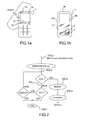
- a host device of this type is for example a mobile phone 1 as schematically represented on the figure 1 . It can still be, for example, a PDA ( Personal Digital Assistant ) organizer , or a self-powered USB key with an I-USER user interface.
- the term portable or pocket is to understand both in the literal sense, but also in the sense of autonomy of power, these portable and pocket devices being provided a generally rechargeable battery, or replaceable.
- the user interface I-USER can typically comprise various elements, including elements of the following list: display screen 10, keyboard 11, various buttons 12, direction keys 13, speaker 14, microphone 15, and so on. general any user interface element that allows to transmit / receive information to one, or a user.
- the host device for example the mobile phone of the figure 1a , includes inside its case, as illustrated very schematically on the figure 1b , an electronic circuitry 16 powered by a battery 17, and a microcircuit card (s) 2, powered by the battery 17 and connected to the circuitry 16 of the telephone via a suitable interface by which it exchanges data.
- a microcircuit card s
- the microcircuit card (s) 2 integrates a MEMS 3 sensor with nano or micro electromechanical system (s), mounted bare in the thickness of the card 2.
- a microcircuit card (s) is a so-called intelligent card , which comprises in a well known manner, and as schematically illustrated on the figure 5 at least one microprocessor circuit ⁇ C associated with a memory M.
- the memory typically comprises an electrically programmable non-volatile memory block, as well as random access memory.
- map when we speak of "map”, we refer to the ⁇ C intelligence of the card which makes it possible to launch applications, and to unroll programs, and in particular to activate the MEMS 3 sensor, to read the measurements at the outputs of the sensor, and interacting with the host device (that is, with the electronic circuitry 16 of this device) typically by means of an electrical contact connection, for example according to the ISO 7816 or USB standard.
- the microprocessor circuit ⁇ C and the MEMS sensor 3 are preferably separate circuits, connected by conductive tracks provided in the thickness of the card. Alternatively, they can be part of the same integrated circuit.
- the calibration method of the invention makes it possible to calibrate the MEMS sensor 3 of the microcircuit card (s) while it is placed, and operational, in a host device 1, with an I-USER user interface, in order to correct the effects of the mechanical stresses undergone until then, described above.
- This method is based on a judicious use of this user interface, to invite a user to perform a calibration of at least one characteristic of the sensor. The user is then invited by the card, still via this user interface, for example via the display screen or the speaker, to follow instructions for carrying out a calibration of the sensor.
- the method comprises a first calibration prompt phase at the initiative of the card.
- This first phase 100.a comprises the emission by the card of an INV-cal calibration prompt of said sensor of the card via said user interface of the host device. For example, a message is displayed on the screen 11 of the host device, prompting to accept the calibration or to cancel it.
- the card then goes into reception waiting phase 100.b, coming from the user interface of the host device, an ACK acceptance of this calibration prompt. In practice, this wait is limited in time, for example to a few tens of seconds counted by a counter, typically a software counting loop 100.c.
- the card terminates the 100.f. If the card receives the expected acceptance ACK, it activates a measurement phase 100.d, and a phase of determining the correction data 100.e from the measurement values.
- the measurement phase 100.d1 comprises the transmission by the card of at least one instruction message via said user interface, making it possible to determine one or more reference data, and at least one activation of the sensor to obtain one or more measures.
- the correction phase 100.e comprises the activation of a calibration algorithm using the measurement or measurements, and the determined reference value or values, for determining DATA-C correction data to be applied to the measurements of the sensor.
- These correction data are typically programmed in memory M of the card, in non-volatile memory. As an option, these correction data are loaded by the card in the volatile memory of the sensor at each power-up, or in non-volatile memory of the sensor at each new calibration, allowing the initialization of the internal adjustment registers of the sensor.
- the senor itself calculates these correction data from the measurement or measurements and from the reference data or data and stores these correction data in the non-volatile memory of the measurement data. sensor.
- the calibration of the sensor consists of a comparison of a value measured by the sensor with a reference value, typically provided by an external measuring device.
- a reference value typically provided by an external measuring device.
- This implementation generally applies to the calibration of sensors that measure a physical quantity related to the environment of the host device. It applies for example to the calibration of a pressure sensor.
- the instruction message M-INST sent in the transmission phase 100.d1 is an invitation to enter a reference data REF 1 , which will be compared with the measurement made by the sensor on request 100. d3 of the map.
- the card After the transmission 100.d1 of the message M-INST, the card goes on hold 100.d2 of the reference value REF 1 , and in parallel starts the measurement 100.d3 in the sensor. It can then go to the correction phase 100.e, to determine a corresponding DATA-C correction data, which the card will then use to correct the measurements provided by the sensor.
- an instruction message M-INST of the measurement phase 100.d is an invitation to place the host device in a reference position Pos i , for compare one or more mes i measurements of the sensor obtained in this reference position, to compare to one or more REF i reference values associated with this reference position Pos i .
- MEMS motion sensors such as accelerometers or inclinometers.
- the card After transmission of the instruction message, the card starts preferably in the queue 100.d2 an ACK confirmation on the user interface indicating that the device is in the Pos position i requested before sending a measurement request 100.d3 to the sensor, and send for example a message indicating that the calibration is in progress, typically by displaying it, or by sending it vocally.
- This measurement phase may comprise several measuring loops, for example N, as many as Pos i reference positions in which to successively place the device. An example will be detailed below with two or three reference positions.
- the card activates the correction phase 100.e, which unwinds a correction algorithm using the one or more measurements Mes i and the reference value REF i , to determine the correction to be applied. to the measurements of the sensor, and program in memory of the card the corresponding DATA-C correction data. This data will then be used by the card to correct the measurements provided by the sensor.
- the card can optionally initialize internal adjustment registers of the sensor with these data, at each power-up, so that the correction is applied by the sensor itself.
- an accelerometer can be an accelerometer or an inclinometer.
- An accelerometer sensor may include one or more accelerometers (or one or more accelerometer measurement axes). When it comprises several accelerometers, they are mounted so that their respective measurement axes are orthogonal two by two.
- the microcircuit card (s) 2 of the host device 1 thus integrates a sensor of the biaxial accelerometer type (or two accelerometers), represented by its two measurement axes x and y.
- the x and y axes are orthogonal in the surface plane S of the card 2, usually rectangular.
- the axis x is parallel to the small side I and the axis y is parallel to the long side L of the card.
- the card is positioned in the host device 1 in known manner, and invariant (for host devices of the same type).
- the host device generally has a substantially flat main surface, here represented by the front of the host device with the screen 10, which is registered substantially in a rectangular shape, defined by a small side IH and a large side LH ( Figures 1a and 1b ).
- the card 2 is placed in the host device as indicated on the figure 1b , with its small dimension I parallel to the small side IH of the host device 1, and its large dimension L parallel to the long side LH, and such that the x, and y axes are oriented as indicated on the figure 2 .
- the two x and y axes are thus orthogonal in a plane parallel to the surface plane of the card and to the main surface plane of the host device.
- a microcircuit card knows how it is positioned in the host device in which it is placed, because in a well known manner and as illustrated on the figure 8 at power up (ON), the card activates an identification procedure called IMEI (for "International Mobile Equipment Identifier” ) , whereby the card issues an identification request REQ_ID to the host device, which in response sends him an IDH identification number. If this IDH number is new to the card (IDH ⁇ OLD), the card is that it is a first power on the card with this device. The card will then launch specific initialization and / or configuration operations of the host device. According to the invention, the card uses this procedure to select a calibration scenario corresponding to the configuration of the sensor relative to the identified host device.
- IMEI for "International Mobile Equipment Identifier”
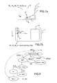
- a first reference position is the flat position on a horizontal and immobile surface as illustrated on the figure 6a . In this position, the main surface of the host device is substantially horizontal.
- the map knows the values of the corresponding accelerations on the x and y axes of the sensor, in the example of zero accelerations (0g), the gravitational force F then being oriented vertically.
- the card therefore associates zero acceleration values 0g, which it can compare with the acceleration measurements Mx on the x axis and My on the y axis, provided by the sensor, for this reference position of the host device.
- the map thus knows the value of the offset on each of the x and y axes: -Mx and -My.
- a second reference position is illustrated on the figure 6b , in which the device is "coated", with the screen on the right in the example: the main surface of the host device is substantially vertical, facing the user (screen 10 on the front face) the device being disposed on the slice, on its largest dimension LH.
- the arrangement and orientation of the x and y axes are then as shown in the figure.
- the gravitational force F causes a non-zero negative acceleration on the x-axis, of -g.
- a third reference position is illustrated on the Figure 6c , in which the device is "upright", facing the user: the main surface of the host device is substantially vertical, facing the user (screen 10 on the front) the device being disposed on the edge, on its plus small size LH.
- the host device 1 is arranged on the edge, on its smallest dimension LH.
- the arrangement and orientation of the x and y axes are as shown in the figure. In this position, the gravitational force F causes a non-zero positive acceleration on the x, + g axis.
- the card performs the measurements in the different positions, then, when all the measurements are made, the card can determine the offset and the gain on each axis, and determine the corrections to be made, for each axis of measurement, on the measures provided by the sensor.
- the calibration scenario depends on the number of measuring axes of the sensor, their positions in the card, and if one wants to calibrate only the offset, or offset and gain.
- the map knows the angle ⁇ that the x axis, respectively y, with the axis IH, respectively LH ( Fig. 7a ).
- the acceleration component on each axis x and y, due to the terrestrial attraction, is known by projection, corresponding to a transfer of coordinates from the repository (IH, LH) of the host device to the sensor mark (X, Y).
- the gravitational force F applies in negative according to IH.
- the following acceleration IH is then equal to + g. In the sensor reference (x, y), this corresponds to an acceleration component equal to gcos ⁇ on x and gcos ( ⁇ / 2- ⁇ ) on y.
- the horizontal reference position of the figure 7a thus gives corresponding Mx 0 , My 0 , Mz 0 measurements for the x and y axes, at zero acceleration, and for the z axis, at an acceleration of ⁇ g (depending on the orientation of the z axis ), and the vertical reference position of the figure 7ba gives measurements Mx 0 , My 0 , Mz 0 corresponding to the x and y axes, to a non-zero acceleration gcos ⁇ on x and gcos ( ⁇ / 2- ⁇ ) on y, and for the z axis, zero acceleration.
- the card can thus determine the offset and the gain, and determine the gain correction for each axis, according to the expected gains G 0x , G 0y , G 0z .
- the calibration phase of a sensor can use different calibration scenarios characterized by one or more reference positions and one or more associated reference values.
- the reference values associated with the reference positions correspond to the values of the acceleration due to the gravitation on each of the measurement axes, in the reference mark formed by the axes of the sensor.
- the instructions given to the user to position the host device include the orientation of the host device, for example, by specifying the position of a characteristic element such as standing device, display screen facing you, device lying down, screen facing you and right .
- the calibration process will successively activate the corresponding calibration scenarios.
- a calibration method according to the invention is activated by the card 2 in the host device 1, on detection of an external event, for example, a power on (ON) of the host device.
- an external event for example, a power on (ON) of the host device.
- the card is also powered on, which initiates an initialization procedure 200.a.
- This internal initialization procedure of the trigger card can for example activate the calibration process of the card sensor.
- the calibration method is triggered at the first power on of the card 2 with the host device 1 which contains it.
- This first power up is detected by the card, in an identification procedure called IMEI, because as indicated above the host device will transmit its IDH identification number, which will be new to the card.
- IMEI identification procedure
- This event is particularly interesting to trigger a calibration process according to the invention, because it can indeed be estimated that once the card inserted and blocked in a host device, the sensor of the card is protected from mechanical stresses as it would be in an encapsulation box.
- a calibration process leads to this privileged moment, thus makes it possible to correct all the mechanical stresses exerted since the provision of the card until its integration into the host device.
- the card will detect the hardware change (new IDH number) and trigger a new calibration procedure, which will make it possible to correct the new mechanical constraints related to this change of material.
- This moment is privileged because, on the one hand, it is easy to detect by the card, linked to the identification procedure of the host device, that it only intervenes once, the first time the card is powered on with this device, that it corrects a priori all the mechanical stresses exerted since the last calibration of the sensor, and that it integrates naturally in a process of initialization which will be perceived by the user as a natural step of setting in place.
- the calibration method can also be triggered at the request of the user, R-USER, via the user interface, corresponding to a functionality offered by the card.
- the invention is not limited to the examples of implementation described and illustrated. It extends to the calibration in operational mode, in the host device, of all MEMS sensors of a microcircuit card (s) requiring calibration, in particular a calibration of an offset and / or a gain.
Abstract
Description
La présente invention concerne la calibration d'un capteur MEMS d'une carte à microcircuit, et plus spécialement un procédé de calibration de ce capteur qui est mis en oeuvre alors que la carte est placée, opérationnelle, dans un dispositif électronique hôte de poche ou portable.The present invention relates to the calibration of a MEMS sensor of a microcircuit card, and more particularly to a calibration method of this sensor which is implemented while the card is placed, operational, in a pocket or electronic host device. portable.
Les cartes à microcircuit sont d'utilisation courante dans des dispositifs électroniques hôtes de poche ou portable, en particulier pour assurer des fonctions de contrôle d'accès sécurisé à des services proposés par le dispositif hôte. Un exemple bien connu est la carte appelée carte SIM, qui utilisée en lien avec un téléphone portable qui permet à son utilisateur, d'accéder au réseau de téléphonie via un fournisseur d'accès. Elle peut être utilisée dans d'autres dispositifs hôtes, par exemple dans des clefs USB. D'autres formats de cartes à microcircuit sont aussi utilisés, comme le format de cartes bancaires.Microcircuit cards are commonly used in hand-held or portable electronic devices, in particular to provide secure access control functions to services offered by the host device. A well-known example is the card called SIM card, which is used in connection with a mobile phone that allows the user to access the telephony network via an access provider. It can be used in other host devices, for example in USB keys. Other microcircuit card formats are also used, such as the credit card format.
Outre les fonctions de contrôle d'accès sécurisé, ces cartes proposent généralement d'autres fonctions ou applications, qui s'ajoutent à celles du dispositif hôte de la carte. Ces fonctionnalités propres à la carte sont d'un accès difficile pour l'utilisateur, car le chemin d'accès est plus enfoui que l'accès aux fonctionnalités du dispositif hôte, et qu'il est variable d'un dispositif hôte à un autre.In addition to the secure access control functions, these cards generally offer other functions or applications, in addition to those of the host device of the card. These map-specific features are difficult for the user to access because the path is deeper than access to the host device's capabilities, and varies from one host device to another. .
Cet accès non aisé aux fonctionnalités de la carte à microcircuit peut être amélioré par l'intégration de capteur(s) à accéléromètre(s) dans la carte, pour réaliser une interface utilisateur plus intuitive avec cette carte, basée sur la détection d'un mouvement ou d'une position, par exemple une inclinaison. On a alors un accès facilité aux fonctionnalités propres à la carte, la détection d'un mouvement ou d'une position par le capteur de la carte provoquant par exemple l'émission d'un affichage, ou d'un message sonore pour l'utilisateur : de cette façon, on remonte une ou des fonctionnalités de la carte en sorte qu'elles soient ainsi proposées directement à l'utilisateur, via l'interface utilisateur du dispositif hôte. L'utilisateur peut alors, à sa guise, activer ou non les fonctionnalités de la carte qui lui sont proposées "spontanément".This uncomplicated access to the features of the microcircuit card can be improved by the integration of sensor (s) accelerometer (s) in the card, to achieve a more intuitive user interface with this card, based on the detection of a movement or position, for example an inclination. There is then easy access to the features specific to the card, the detection of a movement or a position by the sensor of the card causing for example the emission of a display, or a sound message for the user: in this way, one or more functionalities of the card are put back so that they are thus proposed directly to the user, via the user interface of the host device. The user can then, in his own way, activate or not the features of the card that are proposed to him "spontaneously".
En pratique, les capteurs de mouvement utilisés sont comparables à ceux déjà utilisés dans les téléphones portables, organiseurs ou autres dispositifs électroniques de poche ou portables. Par exemple, ce peut être un accéléromètre à un, deux ou trois axes. Ce peut être un inclinomètre, soit typiquement un capteur à deux accéléromètres associé à un microprocesseur qui calcule une inclinaison à partir des mesures d'accélération. D'autres capteurs peuvent être intégrés dans la carte pour offrir d'autres fonctionnalités ou applications. Par exemple, un capteur de pression peut être prévu, notamment pour des fonctionnalités d'altimètre.In practice, the motion sensors used are comparable to those already used in mobile phones, organizers or other handheld or portable electronic devices. For example, it can be a one, two or three axis accelerometer. It can be an inclinometer, or typically a sensor with two accelerometers associated with a microprocessor that calculates an inclination from the acceleration measurements. Other sensors can be integrated into the card to offer other features or applications. For example, a pressure sensor may be provided, especially for altimeter functions.
L'intégration de tels capteurs dans les cartes à microcircuits, qui ont la particularité d'être très minces, est possible, en utilisant des capteurs MEMS, à micro ou nano systèmes électromécaniques, à encombrement réduit, grande sensibilité et faible consommation, montés à nu dans l'épaisseur de ces cartes, c'est-à-dire sous forme de puce, non encore encapsulée dans un boitier. L'encapsulation de la puce de capteur est ainsi assurée par la carte elle-même, dans son épaisseur, utilisant les techniques d'encapsulation éprouvées dans ce domaine.The integration of such sensors in microcircuit cards, which have the particularity of being very thin, is possible, using MEMS sensors, micro or nano electromechanical systems, compact, high sensitivity and low consumption, mounted to naked in the thickness of these cards, that is to say in the form of chip, not yet encapsulated in a box. The encapsulation of the sensor chip is thus ensured by the card itself, in its thickness, using the encapsulation techniques tested in this field.
Les capteurs MEMS du commerce, en boitier, sont habituellement calibrés en usine, pour déterminer des valeurs de réglage de leurs caractéristiques de réponse. Si on prend en exemple les capteurs MEMS à accéléromètre(s), ces capteurs sont calibrés sur chaque axe de mesure avec une valeur de réglage de l'offset, pour que le capteur fournisse une valeur nulle d'accélération (0g) en réponse à une accélération nulle, et une valeur de réglage du gain, pour que le capteur ait la sensibilité attendue. Ces capteurs contiennent ainsi des registres contenant des valeurs de réglage ("trimming values") d'offset et de gain qui sont utilisées en interne du capteur, ou par un microprocesseur externe, dans un algorithme de correction qui corrige la mesure sur chaque axe. A titre d'exemple, on peut citer l'accéléromètre triaxe MEMS commercialisé par la société STMICROELECTRONICS sous la référence LIS3LV02DQ, qui contient ainsi une mémoire non volatile contenant les valeurs usine de réglage de l'offset et du gain sur chaque axe. Ces valeurs de réglage sont chargées à chaque mise sous tension dans des registres de réglage du capteur, pour être utilisées par un algorithme de correction mis en oeuvre dans le capteur, pour fournir des mesures corrigées en sortie.The commercially available MEMS sensors are usually calibrated at the factory to determine setting values for their response characteristics. If MEMS sensors with accelerometer (s) are used as examples, these sensors are calibrated on each measurement axis with an offset adjustment value, so that the sensor provides a zero acceleration value (0g) in response to a zero acceleration, and a gain adjustment value, so that the sensor has the expected sensitivity. These sensors thus contain registers containing offset and gain adjustment values ("trimming values") that are used internally by the sensor, or by an external microprocessor, in a correction algorithm that corrects the measurement on each axis. By way of example, mention may be made of the tri-axial MEMS accelerometer marketed by the company STMICROELECTRONICS under the reference LIS3LV02DQ, which thus contains a non-volatile memory containing the factory setting values of the offset and the gain on each axis. These setting values are loaded at each power-up in sensor adjustment registers, for use by a correction algorithm implemented in the sensor, to provide corrected output measurements.
Cette calibration en sortie d'usine est nécessaire, compte-tenu des différentes contraintes mécaniques qui peuvent s'exercer au cours de la fabrication des éléments sensibles de ces capteurs, qui sont de petites dimensions, et utilisent généralement une ou des membranes ou poutres micro usinées, dont le déplacement, la vibration ou la déformation est la grandeur physique à la base de la mesure qu'ils délivrent.This calibration at the factory outlet is necessary, given the various mechanical constraints that may be exerted during the manufacture of the sensitive elements of these sensors, which are small, and generally use one or more membranes or micro beams. machined, whose displacement, vibration or deformation is the physical magnitude at the base of the measurement they deliver.
On comprend que l'intégration à nu de ces capteurs dans une carte à microcircuit, nécessite de prévoir une calibration supplémentaire en fin de fabrication des cartes, pour corriger les effets propres aux contraintes mécaniques de fabrication et d'encapsulation dans la carte (montage et collage de la puce de capteur sur une couche support intermédiaire, réalisation des connexions, encartage, découpe des cartes...). Cette calibration sera semblable en ses principes à la calibration réalisée en sortie d'usine sur les capteurs en boitiers. Cette correction à appliquer aux mesures du capteur d'une carte à microcircuit(s) s'ajoute le cas échéant à la calibration déjà opérée en interne par le capteur, sur la base des valeurs de réglage usine. Pour déterminer la correction de gain supplémentaire à appliquer aux mesures fournies par le capteur, la carte doit connaitre le gain (ou la sensibilité) attendu G0 du capteur. Ceci est facilement réalisable en intégrant cette valeur de référence de gain du capteur dans le flot de données de personnalisation de la carte, qui est programmé dans la phase de personnalisation électrique, en fin de fabrication. La calibration est réalisée en utilisant cette valeur de référence. La carte dispose alors de valeurs de réglage du capteur qui viennent corriger les effets des contraintes mécaniques liées à l'intégration du capteur dans la carte. Cette correction s'ajoute à celle déjà opérée le cas échéant en interne dans le capteur, sur la base des valeurs de réglage usine. On peut aussi prévoir une unique calibration du capteur, en fin de fabrication de la carte, pour obtenir les valeurs de réglage du capteur qui pourront aussi être utilisées dans un algorithme de correction mis en oeuvre par la carte, appliqué aux mesures fournies par le capteur. Dans une telle variante, il est aussi possible de prévoir que le capteur intègre des registres de réglage qui peuvent être initialisés avec les valeurs de réglage déterminées par la carte, avec un algorithme de correction implémenté en interne dans le capteur.It is understood that the naked integration of these sensors in a microcircuit card, requires to provide an additional calibration at the end of the card manufacturing, to correct the effects of the mechanical constraints of manufacturing and encapsulation in the card (mounting and gluing of the sensor chip on an intermediate support layer, making connections, inserting, cutting cards ...). This calibration will be similar in principle to the calibration performed at the factory on the sensors in boxes. This correction to be applied to the sensor measurements of a microcircuit card (s) is added, if necessary, to the calibration already carried out internally by the sensor, on the basis of the factory setting values. To determine the additional gain correction to be applied to the measurements provided by the sensor, the card must know the expected gain (or sensitivity) G 0 of the sensor. This is easily accomplished by integrating this sensor gain reference value into the personalization data stream of the card, which is programmed in the electric personalization phase, at the end of manufacture. Calibration is performed using this reference value. The card then has sensor adjustment values that correct the effects of mechanical stresses related to the integration of the sensor in the card. This correction is in addition to the correction that has already been made internally in the sensor, based on the factory setting values. It is also possible to provide a single calibration of the sensor, at the end of manufacture of the card, to obtain the sensor adjustment values that can also be used in a correction algorithm implemented by the card, applied to the measurements provided by the sensor. . In such a variant, it is also possible to provide that the sensor integrates setting registers that can be initialized with the adjustment values determined by the card, with a correction algorithm implemented internally in the sensor.
Ainsi, on sait intégrer un capteur à nu dans une carte, et le calibrer dans cette carte. Mais une fois la carte fabriquée et mise en vente, d'autres contraintes mécaniques vont s'exercer qui sont liées à la nature, portable, de ces cartes et à leurs utilisations. Notamment ces cartes sont amenées à être manipulées, notamment distribuées dans les points de vente où elles sont manipulées par les vendeurs. Elles sont par ailleurs destinées à être insérées dans un dispositif hôte, par exemple un téléphone, une clef USB, un organiseur (PDA)......Si on prend l'exemple des cartes SIM, ces cartes sont vendues dans un support dont elles sont détachables : il faut alors détacher la carte de son support avant de la placer dans son dispositif hôte (téléphone, clef USB par exemple), ce qui se fait en exerçant une pression mécanique forte, généralement avec les doigts, sur cette carte. Elle doit ensuite être insérée et bloquée mécaniquement dans le dispositif hôte. Cette opération exerce des torsions et forces mécaniques importantes sur la carte. En outre, l'évolution technologique et l'offre correspondante sur le marché de produits toujours plus innovants, conduisent certains utilisateurs à changer très souvent de matériel, pour suivre cette évolution. La carte elle ne change pas pour autant. Il faut alors enlever la carte de l'ancien matériel hôte, ce qui ne se fait pas sans exercer des efforts sur la carte, pour à nouveau l'insérer et la bloquer dans un nouveau dispositif hôte.Thus, we know how to integrate a bare sensor in a card, and calibrate it in this map. But once the card is manufactured and put on sale, other mechanical constraints will be exerted that are related to the nature, portable, these cards and their uses. In particular these cards are brought to be handled, in particular distributed in the sales points where they are handled by the sellers. They are also intended to be inserted into a host device, for example a phone, a USB key, an organizer (PDA) ...... If we take the example of SIM cards, these cards are sold in a support which they are detachable: it is then necessary to detach the card from its support before placing it in its host device (telephone, USB key for example), which is done by exerting a strong mechanical pressure, generally with the fingers, on this card . It must then be inserted and mechanically locked into the host device. This operation exerts significant torsions and mechanical forces on the map. In addition, the technological evolution and the corresponding offer on the market of increasingly innovative products, lead some users to change very often material, to follow this evolution. The map does not change so far. It is then necessary to remove the card from the old host hardware, which is not done without exerting efforts on the card, to insert it again and block it in a new host device.
Toutes ces manipulations des cartes à microcircuit, liées à leur utilisation, amènent des contraintes mécaniques. Compte tenu notamment de la souplesse de ces cartes, ces contraintes ne sont pas sans effets sur la réponse de(s) capteur(s) MEMS qu'elle contient. Les valeurs de réglage du capteur ne sont plus correctes. La carte dispose alors de mesures qui peuvent être biaisées, ou moins précises, ce qui peut être gênant selon l'application visée.All these manipulations of microcircuit cards, related to their use, bring mechanical constraints. Given the flexibility of these cards, these constraints are not without effects on the response of the MEMS sensor (s) that it contains. The sensor setting values are no longer correct. The card then has measures that can be biased, or less precise, which can be annoying depending on the intended application.
L'invention apporte une solution à ce problème technique en permettant une nouvelle calibration d'un capteur MEMS d'une carte à microcircuit(s) d'un dispositif électronique hôte de poche ou portable, à interface utilisateur, basée sur une utilisation judicieuse de cette interface utilisateur, pour inviter un utilisateur à procéder à une calibration d'au moins une caractéristique du capteur. L'utilisateur est ensuite invité par la carte, toujours via cette interface utilisateur à suivre des instructions pour procéder à une calibration du capteur.The invention provides a solution to this technical problem by allowing a new calibration of a MEMS sensor of a microcircuit card (s) of a handheld or portable electronic host device, with a user interface, based on a judicious use of this user interface, to invite a user to perform a calibration of at least one characteristic of the sensor. The user is then prompted by the card, always via this user interface to follow instructions to carry out a calibration of the sensor.
L'invention concerne donc un procédé de calibration d'au moins un capteur MEMS d'une carte à microcircuits dans un dispositif électronique hôte de poche ou portable comportant une interface utilisateur, caractérisé en ce que pour chaque capteur, il comprend l'émission par la carte d'une invite de calibration dudit capteur de la carte via ladite interface utilisateur du dispositif hôte, et en ce qu'une acceptation de ladite invite de calibration reçue par la carte, via ladite interface utilisateur, active un processus de la carte, de calibration dudit capteur, ledit processus de calibration comprenant une phase de mesure et une phase de calibration.The invention therefore relates to a method for calibrating at least one MEMS sensor of a microcircuit card in a pocket or portable electronic host device comprising a user interface, characterized in that for each sensor, it comprises the transmission by the card of a calibration prompt of said card sensor via said user interface of the host device, and that an acceptance of said calibration prompt received by the card, via said user interface, activates a card process, calibration of said sensor, said calibration process comprising a measurement phase and a calibration phase.
La phase de mesure comprend l'émission par la carte d'au moins un message d'instruction via ladite interface utilisateur, permettant de déterminer une donnée de référence, et au moins une activation du capteur pour obtenir une mesure correspondante. La phase de calibration comprend l'activation d'un algorithme de calibration utilisant la ou les mesures, et la ou les données de référence déterminées. La phase de correction comprend l'activation d'un algorithme de calibration utilisant la ou les mesures, et la ou les données de référence déterminées, pour calculer des données de correction correspondantes.The measurement phase comprises the transmission by the card of at least one instruction message via said user interface, making it possible to determine a datum of reference, and at least one activation of the sensor to obtain a corresponding measurement. The calibration phase comprises the activation of a calibration algorithm using the measurement or measurements and the reference data or data determined. The correction phase includes activating a calibration algorithm using the one or more measurements, and the one or more determined reference data, to calculate corresponding correction data.
Selon un aspect de l'invention, un message d'instruction de la phase de mesure est une invitation à entrer une valeur de référence à comparer avec la mesure effectuée par le capteur.According to one aspect of the invention, an instruction message of the measurement phase is an invitation to enter a reference value to be compared with the measurement made by the sensor.
Selon un autre aspect de l'invention, un message d'instruction de la phase de mesure est une invitation à placer le dispositif hôte dans une position de référence, pour la calibration du capteur, pour comparer une ou des mesures du capteur obtenues dans cette position de référence, à une ou des valeurs de référence associées à cette position de référence.According to another aspect of the invention, an instruction message of the measurement phase is an invitation to place the host device in a reference position, for the calibration of the sensor, to compare one or more sensor measurements obtained in this reference position, to one or more reference values associated with this reference position.
Une fois la ou les mesures acquises, la carte active la phase de calibration, qui déroule un algorithme de calibration utilisant la ou les mesures et la ou les valeurs de référence, pour déterminer la correction à appliquer aux mesures du capteur, et programmer en mémoire non volatile des données de correction correspondantes.Once the acquired measurement (s), the card activates the calibration phase, which runs a calibration algorithm using the measurement (s) and the reference value (s), to determine the correction to be applied to the measurements of the sensor, and to program in memory non-volatile corresponding correction data.
Dans une mise en oeuvre préférée, ledit procédé de calibration est activé à la mise sous tension du dispositif hôte, dans une phase d'initialisation de la carte. Avantageusement, il est activé à la première mise sous tension de la carte avec le dispositif hôte qui la contient.In a preferred implementation, said calibration method is activated when the host device is powered up, in a card initialization phase. Advantageously, it is activated the first time the card is powered on with the host device that contains it.
L'invention concerne aussi une carte à microcircuit(s) à capteur(s) MEMS comprenant des moyens pour proposer une calibration du ou des capteurs MEMS qu'elle contient, utilisant une interface utilisateur du dispositif hôte dans lequel elle est insérée.The invention also relates to a MEMS sensor microcircuit card (s) comprising means for proposing a calibration of the MEMS sensor (s) it contains, using a user interface of the host device in which it is inserted.
D'autres caractéristiques et avantages de l'invention sont détaillés dans la description suivante de modes de réalisation de l'invention, en référence aux dessins annexés, dans lesquels :
- les
figures 1a et 1b sont des schémas simplifiés d'un dispositif électronique de poche ou portable hôte d'une carte à microcircuit(s) à capteur à accéléromètre(s) intégré; - la
figure 2 est un synoptique d'une phase d'invite de calibration d'un procédé de calibration selon l'invention; - les
figures 3 et 4 sont des synoptiques d'une phase de mesure d'un procédé de calibration selon l'invention, suivant une première et une deuxième mise en oeuvre; - la
figure 5 est un schéma bloc d'une carte à microcircuit(s) comprenant un capteur à accéléromètre(s) deux axes x et y; - les
figures 6a à 6c illustrent différentes positions de référence d'un dispositif hôte correspondant à un scénario de calibration pour un capteur accéléromètre à deux ou trois axes de mesure; - les
figures 7a et 7b illustrent une variante d'un scénario de calibration d'un capteur à deux ou trois axes de mesure; - la
figure 8 est un synoptique illustrant un schéma d'activation d'un procédé de calibration d'un capteur ou de capteur(s) d'une carte à microcircuit d'un dispositif hôte, selon l'invention.
- the
Figures 1a and 1b are simplified diagrams of a pocket or portable electronic device host of a microcircuit card (s) with built-in accelerometer sensor (s); - the
figure 2 is a block diagram of a calibration prompt phase of a calibration method according to the invention; - the
Figures 3 and 4 are synoptics of a measurement phase of a calibration method according to the invention, according to a first and a second implementation; - the
figure 5 is a block diagram of a microcircuit card (s) comprising an accelerometer sensor (s) two axes x and y; - the
Figures 6a to 6c illustrate different reference positions of a host device corresponding to a calibration scenario for an accelerometer sensor with two or three measurement axes; - the
Figures 7a and 7b illustrate a variant of a calibration scenario of a sensor with two or three measurement axes; - the
figure 8 is a block diagram illustrating an activation diagram of a method for calibrating a sensor or sensor (s) of a microcircuit card of a host device, according to the invention.
L'invention concerne un procédé de calibration d'un capteur MEMS intégré d'une carte à microcircuit(s) dans un dispositif électronique hôte de poche ou portable comportant une interface utilisateur.The invention relates to a method for calibrating an integrated MEMS sensor of a microcircuit card (s) in a pocket or portable electronic device comprising a user interface.
Un dispositif hôte de ce type est par exemple un téléphone portable 1 comme schématiquement représenté sur la
Le dispositif hôte, par exemple le téléphone portable de la
La carte à microcircuit(s) 2 intègre un capteur MEMS 3 à nano ou micro système(s) électromécanique(s), monté à nu dans l'épaisseur de la carte 2. Une carte à microcircuit(s) est une carte dite intelligente, qui comprend de manière bien connue, et comme illustré schématiquement sur la
Le circuit microprocesseur µC et le capteur MEMS 3 sont préférentiellement des circuits distincts, connectés par des pistes conductrices prévues dans l'épaisseur de la carte. En variante, ils peuvent faire partie d'un même circuit intégré.The microprocessor circuit μC and the
Le procédé de calibration de l'invention, permet de calibrer le capteur MEMS 3 de la carte à microcircuit(s) alors qu'elle est placée, et opérationnelle, dans un dispositif hôte 1, à interface utilisateur I-USER, afin de corriger les effets des contraintes mécaniques subies jusqu'alors, décrites supra. Ce procédé est basé sur une utilisation judicieuse de cette interface utilisateur, pour inviter un utilisateur à procéder à une calibration d'au moins une caractéristique du capteur. L'utilisateur est ensuite invité par la carte, toujours via cette interface utilisateur, par exemple via l'écran d'affichage ou le haut-parleur, à suivre des instructions pour procéder à une calibration du capteur.The calibration method of the invention makes it possible to calibrate the
Selon l'invention, et comme illustré sur le synoptique de la
La phase de mesure 100.d1 comprend l'émission par la carte d'au moins un message d'instruction via ladite interface utilisateur, permettant de déterminer une ou des données de référence, et au moins une activation du capteur pour obtenir une ou des mesures. La phase de correction 100.e comprend l'activation d'un algorithme de calibration utilisant la ou les mesures, et la ou les valeurs de référence déterminées, pour déterminer des données de correction DATA-C à appliquer aux mesures du capteur. Ces données de correction sont typiquement à programmer en mémoire M de la carte, en mémoire non volatile. En option, ces données de correction sont chargées par la carte en mémoire volatile du capteur à chaque mise sous tension, ou bien en mémoire non volatile du capteur à chaque nouvelle calibration, permettant l'initialisation des registres de réglage interne du capteur.The measurement phase 100.d1 comprises the transmission by the card of at least one instruction message via said user interface, making it possible to determine one or more reference data, and at least one activation of the sensor to obtain one or more measures. The correction phase 100.e comprises the activation of a calibration algorithm using the measurement or measurements, and the determined reference value or values, for determining DATA-C correction data to be applied to the measurements of the sensor. These correction data are typically programmed in memory M of the card, in non-volatile memory. As an option, these correction data are loaded by the card in the volatile memory of the sensor at each power-up, or in non-volatile memory of the sensor at each new calibration, allowing the initialization of the internal adjustment registers of the sensor.
En variante, le capteur calcule lui-même ces données de correction à partir de la ou des mesures et de la ou des données de référence et mémorise ces données de correction dans la mémoire non volatile du capteur.As a variant, the sensor itself calculates these correction data from the measurement or measurements and from the reference data or data and stores these correction data in the non-volatile memory of the measurement data. sensor.
Dans une première mise en oeuvre d'un procédé de calibration selon l'invention illustrée sur le synoptique de la
Dans une autre mise en oeuvre d'un procédé de calibration selon l'invention, un message d'instruction M-INST de la phase de mesure 100.d est une invitation à placer le dispositif hôte dans une position de référence Posi, pour comparer une ou des mesures mesi du capteur obtenues dans cette position de référence, à comparer à une ou des valeurs de référence REFi associée(s) à cette position de référence Posi. Une telle mise en oeuvre s'applique notamment aux capteurs MEMS de mouvements, tels qu'accéléromètres ou inclinomètres.In another implementation of a calibration method according to the invention, an instruction message M-INST of the measurement phase 100.d is an invitation to place the host device in a reference position Pos i , for compare one or more mes i measurements of the sensor obtained in this reference position, to compare to one or more REF i reference values associated with this reference position Pos i . Such an implementation applies in particular to MEMS motion sensors, such as accelerometers or inclinometers.
Après envoi du message d'instruction, la carte se met de préférence en attente 100.d2 d'une confirmation ACK via l'interface utilisateur, indiquant que le dispositif est dans la position Posi demandée, avant d'envoyer une requête de mesure 100.d3 au capteur, et émettre par exemple un message indiquant que la calibration est en cours, typiquement en l'affichant, ou en l'émettant vocalement. Cette phase de mesure peut comprendre plusieurs boucles de mesure, par exemple N, autant que de positions de référence Posi dans lesquelles successivement placer le dispositif. Un exemple sera détaillé ci-après avec deux ou trois positions de référence.After transmission of the instruction message, the card starts preferably in the queue 100.d2 an ACK confirmation on the user interface indicating that the device is in the Pos position i requested before sending a measurement request 100.d3 to the sensor, and send for example a message indicating that the calibration is in progress, typically by displaying it, or by sending it vocally. This measurement phase may comprise several measuring loops, for example N, as many as Pos i reference positions in which to successively place the device. An example will be detailed below with two or three reference positions.
A la place de la confirmation ACK, ou après réception de cette confirmation :
- la carte peut attendre que les valeurs d'accélération mesurées restent stables pendant un temps prédéterminé, par exemple une seconde, et émettre par exemple un message indiquant que la calibration est en cours, typiquement en l'affichant, ou en l'émettant vocalement.
- la carte peut attendre un temps prédéterminé avant d'activer le capteur pour la mesure,
par exemple 3 secondes, et indiquer, de préférence afficher, le décompte des secondes avant mesure.
- the card can wait for the measured acceleration values to remain stable for a predetermined time, for example a second, and to emit for example a message indicating that the calibration is in progress, typically by displaying it, or by sending it vocally.
- the card can wait a predetermined time before activating the sensor for the measurement, for example 3 seconds, and indicate, preferably display, the count of seconds before measurement.
Une fois la ou les mesures Mesi acquises, la carte active la phase de correction 100.e, qui déroule un algorithme de correction utilisant la ou lesdites mesures Mesi et la ou les valeurs de référence REFi, pour déterminer la correction à appliquer aux mesures du capteur, et programmer en mémoire de la carte des données de correction DATA-C correspondantes. Ces données seront utilisées ensuite par la carte pour corriger les mesures fournies par le capteur. Dans une variante déjà évoquée, la carte peut le cas échéant initialiser des registres de réglage internes du capteur avec ces données, à chaque mise sous-tension, de sorte que la correction est appliquée par le capteur lui-même.Once the measurement Mes i acquired, the card activates the correction phase 100.e, which unwinds a correction algorithm using the one or more measurements Mes i and the reference value REF i , to determine the correction to be applied. to the measurements of the sensor, and program in memory of the card the corresponding DATA-C correction data. This data will then be used by the card to correct the measurements provided by the sensor. In a variant already mentioned, the card can optionally initialize internal adjustment registers of the sensor with these data, at each power-up, so that the correction is applied by the sensor itself.
A titre d'illustration, le procédé de calibration selon l'invention est expliqué ci-après en prenant en exemple une carte 2 intégrant un capteur MEMS à accéléromètre(s). Ce peut être un accéléromètre ou un inclinomètre. Un capteur à accéléromètre(s) peut comprendre un ou plusieurs accéléromètres (ou un ou plusieurs axes de mesure d'accéléromètre). Quand il comprend plusieurs accéléromètres, ils sont montés en sorte que leurs axes de mesure respectifs soient orthogonaux deux à deux.By way of illustration, the calibration method according to the invention is explained below by taking as an example a
Dans un premier exemple illustré sur la
En pratique, une carte à microcircuit(s) sait comment elle est positionnée dans le dispositif hôte dans lequel elle est placée, car de manière bien connue et comme illustré sur la
De manière plus détaillée en référence aux
Pour calibrer également le gain du capteur sur chaque axe, il faut en outre mesurer une accélération non nulle sur chaque axe, pour obtenir un deuxième point de la réponse du capteur. Ceci nécessite dans l'exemple d'utiliser deux autres positions de référence différentes, pour obtenir pour chaque axe, une mesure pour une accélération nulle, une mesure pour une accélération non nulle.To calibrate also the gain of the sensor on each axis, it is necessary to besides measuring a non-zero acceleration on each axis, to obtain a second point of the response of the sensor. This requires in the example to use two other different reference positions, to obtain for each axis, a measurement for a zero acceleration, a measurement for a non-zero acceleration.
Une deuxième position de référence est illustrée sur la
Une troisième position de référence est illustrée sur la
En pratique, la carte effectue les mesures dans les différentes positions, puis, quand toutes les mesures sont effectuées, la carte peut déterminer l'offset et le gain sur chaque axe, et déterminer les corrections à effectuer, pour chaque axe de mesure, sur les mesures fournies par le capteur.In practice, the card performs the measurements in the different positions, then, when all the measurements are made, the card can determine the offset and the gain on each axis, and determine the corrections to be made, for each axis of measurement, on the measures provided by the sensor.
On comprend que le scénario de calibration dépend du nombre d'axes de mesure du capteur, de leurs positions dans la carte, et si on veut calibrer seulement l'offset, ou l'offset et le gain.It is understood that the calibration scenario depends on the number of measuring axes of the sensor, their positions in the card, and if one wants to calibrate only the offset, or offset and gain.
Notamment, si on a deux axes de mesures x et z, orthogonaux, tel que l'axe z est orthogonal au plan de surface de la carte, et donc au plan de la surface principale du dispositif hôte, deux mesures suffisent, correspondant aux deux positions des
On comprend que pour un accéléromètre trois axes x, y et z, il faut une mesure du capteur dans chacune des trois positions des
Dans un perfectionnement illustré sur les
- l'axe de mesure z soit orthogonal au plan de surface de la carte;
- les deux axes x et y sont orthogonaux dans le plan de surface de la carte, chacun faisant un angle prédéterminé α avec un bord correspondant I, L de la carte. Comme la carte sait dans quel dispositif hôte 1 elle est montée, elle connaît l'angle que fait chacun axe x et y avec les dimensions LH et IH du dispositif hôte. Dans l'exemple illustré c'est le même angle α Une telle configuration est intéressante, car elle permet de calibrer chacun des trois axes x, y et z en utilisant uniquement deux positions, en utilisant un transfert de coordonnées entre le repère défini par les dimensions LH et IH et le repère défini par les axes x et y.
- the measurement axis z is orthogonal to the surface plane of the card;
- the two x and y axes are orthogonal in the surface plane of the map, each making a predetermined angle α with a corresponding edge I, L of the map. Since the card knows which
host device 1 it is mounted on, it knows the angle that each axis x and y has with the dimensions LH and IH of the host device. In the illustrated example it is the same angle α Such a configuration is interesting because it makes it possible to calibrate each of the three axes x, y and z using only two positions, by using a transfer of coordinates between the reference defined by the dimensions LH and IH and the mark defined by the x and y axes.
Dans l'exemple, la carte connait l'angle α que fait l'axe x, respectivement y, avec l'axe IH, respectivement LH (
Quand le dispositif hôte est dans une position verticale, par exemple couché et l'écran à droite comme illustré sur la
Ainsi, la phase de calibration d'un capteur, peut utiliser différents scénarios de calibration caractérisés par une ou des positions de référence et une ou des valeurs de référence associées. Notamment pour un capteur à accéléromètre(s) les valeurs de référence associées aux positions de référence correspondent aux valeurs de l'accélération due à la gravitation sur chacun des axes de mesure, dans le repère formé par les axes du capteur.Thus, the calibration phase of a sensor can use different calibration scenarios characterized by one or more reference positions and one or more associated reference values. In particular for an accelerometer sensor (s) the reference values associated with the reference positions correspond to the values of the acceleration due to the gravitation on each of the measurement axes, in the reference mark formed by the axes of the sensor.
En pratique, les indications données à l'utilisateur pour positionner le dispositif hôte comprennent l'orientation du dispositif hôte, par exemple, en précisant la position d'un élément caractéristique tel que dispositif positionné debout, écran d'affichage face à vous, dispositif couché, écran face à vous et à droite...).In practice, the instructions given to the user to position the host device include the orientation of the host device, for example, by specifying the position of a characteristic element such as standing device, display screen facing you, device lying down, screen facing you and right ...).
Si la carte comprend plusieurs capteurs, par exemple un capteur de pression, et un capteur à accéléromètre(s), le procédé de calibration activera successivement les scénarios de calibration correspondants.If the card comprises several sensors, for example a pressure sensor, and an accelerometer sensor (s), the calibration process will successively activate the corresponding calibration scenarios.
Selon un autre aspect de l'invention, et comme illustré sur la
De préférence, le procédé de calibration est déclenché à la première mise sous tension de la carte 2 avec le dispositif hôte 1 qui l'a contient. Cette première mise sous tension est détectée par la carte, dans une procédure d'identification dite IMEI, car comme indiqué précédemment le dispositif hôte va transmettre son numéro d'identification IDH, qui sera nouveau pour la carte. Cet évènement est particulièrement intéressant pour déclencher un procédé de calibration selon l'invention, car on peut en effet estimer qu'une fois la carte insérée et bloquée dans un dispositif hôte, le capteur de la carte est protégé des contraintes mécaniques comme il le serait dans un boitier d'encapsulation. Un procédé de calibration conduit à ce moment privilégié, permet ainsi de corriger toutes les contraintes mécaniques exercées depuis la mise à disposition de la carte jusqu'à son intégration dans le dispositif hôte. Ensuite, à chaque fois que l'utilisateur change de matériel, et que la carte est enlevée de son dispositif hôte pour être placée dans un nouveau, la carte détectera le changement de matériel (nouveau numéro IDH) et déclenchera une nouvelle procédure de calibration, qui permettra de corriger les nouvelles contraintes mécaniques liées à ce changement de matériel. Ce moment est privilégié, car d'une part il est facile à détecter par la carte, lié à la procédure d'identification du dispositif hôte, qu'il n'intervient qu'une fois, à la première mise sous tension de la carte avec ce dispositif, qu'il corrige a priori toutes les contraintes mécaniques exercées depuis la dernière calibration du capteur, et qu'il s'intègre naturellement dans un processus d'initialisation qui sera ainsi perçu par l'utilisateur comme une étape naturelle de mise en place.Preferably, the calibration method is triggered at the first power on of the
Dans une option supplémentaire, on peut prévoir que le procédé de calibration peut être aussi déclenché sur requête de l'utilisateur, R-USER, via l'interface utilisateur, correspondant à une fonctionnalité offerte par la carte.In an additional option, it can be provided that the calibration method can also be triggered at the request of the user, R-USER, via the user interface, corresponding to a functionality offered by the card.
L'invention ne se limite pas aux exemples de mise en oeuvre décrits et illustrés. Elle s'étend à la calibration en opérationnel, dans le dispositif hôte, de tous capteurs MEMS d'une carte à microcircuit(s) nécessitant une calibration, notamment une calibration d'un offset et/ou d'un gain.The invention is not limited to the examples of implementation described and illustrated. It extends to the calibration in operational mode, in the host device, of all MEMS sensors of a microcircuit card (s) requiring calibration, in particular a calibration of an offset and / or a gain.
Claims (16)
Applications Claiming Priority (1)
| Application Number | Priority Date | Filing Date | Title |
|---|---|---|---|
| FR0905347A FR2952437B1 (en) | 2009-11-06 | 2009-11-06 | METHOD FOR CALIBRATING A MEMS SENSOR OF A MICROCIRCUIT CARD (S) IN A POCKET OR PORTABLE ELECTRONIC DEVICE |
Publications (2)
| Publication Number | Publication Date |
|---|---|
| EP2320195A1 true EP2320195A1 (en) | 2011-05-11 |
| EP2320195B1 EP2320195B1 (en) | 2014-01-08 |
Family
ID=42309670
Family Applications (1)
| Application Number | Title | Priority Date | Filing Date |
|---|---|---|---|
| EP20100189771 Not-in-force EP2320195B1 (en) | 2009-11-06 | 2010-11-03 | Calibration method of and calibration device for a MEMS sensor of a microcircuit board in a portable electronic device |
Country Status (2)
| Country | Link |
|---|---|
| EP (1) | EP2320195B1 (en) |
| FR (1) | FR2952437B1 (en) |
Citations (2)
| Publication number | Priority date | Publication date | Assignee | Title |
|---|---|---|---|---|
| US20070270721A1 (en) * | 2006-05-22 | 2007-11-22 | Apple Computer, Inc. | Calibration techniques for activity sensing devices |
| US20080254822A1 (en) * | 2007-04-12 | 2008-10-16 | Patrick Tilley | Method and System for Correlating User/Device Activity with Spatial Orientation Sensors |
-
2009
- 2009-11-06 FR FR0905347A patent/FR2952437B1/en not_active Expired - Fee Related
-
2010
- 2010-11-03 EP EP20100189771 patent/EP2320195B1/en not_active Not-in-force
Patent Citations (2)
| Publication number | Priority date | Publication date | Assignee | Title |
|---|---|---|---|---|
| US20070270721A1 (en) * | 2006-05-22 | 2007-11-22 | Apple Computer, Inc. | Calibration techniques for activity sensing devices |
| US20080254822A1 (en) * | 2007-04-12 | 2008-10-16 | Patrick Tilley | Method and System for Correlating User/Device Activity with Spatial Orientation Sensors |
Also Published As
| Publication number | Publication date |
|---|---|
| EP2320195B1 (en) | 2014-01-08 |
| FR2952437A1 (en) | 2011-05-13 |
| FR2952437B1 (en) | 2011-11-25 |
Similar Documents
| Publication | Publication Date | Title |
|---|---|---|
| EP1984696B1 (en) | Motion capture device and associated method | |
| US11797970B2 (en) | Point of sale device with cradle for mobile computing device | |
| EP2600104B1 (en) | Inertial micro-sensor of rotational movements | |
| EP2923227B1 (en) | Method for automatically recognising a moving magnetic object | |
| WO2011067245A1 (en) | System and method for assisting the driver of a biomechanically driven vehicle including at least one wheel | |
| EP2492417B1 (en) | Method for assistance with the placement of construction elements of a civil engineering structure | |
| US11665817B2 (en) | Tamper detection based on flexible member connecting circuitry elements | |
| WO2004051391A2 (en) | Method and device for capturing the movement of a solid using at least one camera and one angular sensor | |
| WO2015058986A1 (en) | Method for indoor and outdoor positioning and portable device implementing such a method | |
| US11663368B2 (en) | Tamper detection based on removal of fastener from recess | |
| EP2815210A1 (en) | Compact device for detecting at least one acceleration and one speed of rotation | |
| CA2676236C (en) | Portable authentication device | |
| EP2320195B1 (en) | Calibration method of and calibration device for a MEMS sensor of a microcircuit board in a portable electronic device | |
| EP2965106B1 (en) | Method for automatically recognising a magnetic object | |
| FR3000263A1 (en) | DETECTION OF A TRANSACTIONAL DEVICE | |
| EP2323074B1 (en) | Method for manufacturing pocket or portable electronic entities with MEMS sensors | |
| FR2958096A1 (en) | METHOD AND SYSTEM FOR CALIBRATION, RECORDING MEDIUM FOR THIS METHOD | |
| EP2268999A1 (en) | System and method for determining parameters representing orientation of a solid in movement subject to two vector fields | |
| EP3564626B1 (en) | Method of initialising a sensor network | |
| WO2005088434A1 (en) | Method for recognising the path of the point of a body on a support | |
| EP3881222A1 (en) | Method for automatically detecting facial impersonation | |
| US9871897B1 (en) | Sensor stack having a graphical element formed by physical vapor deposition | |
| EP2158721B1 (en) | Method and device for detecting an attempt to substitute an original casing portion of an electronic system with a replacement casing portion | |
| EP2251643A1 (en) | Chip card for an electronic entity | |
| FR3129131A1 (en) | Connected bike pedal |
Legal Events
| Date | Code | Title | Description |
|---|---|---|---|
| PUAI | Public reference made under article 153(3) epc to a published international application that has entered the european phase |
Free format text: ORIGINAL CODE: 0009012 |
|
| AK | Designated contracting states |
Kind code of ref document: A1 Designated state(s): AL AT BE BG CH CY CZ DE DK EE ES FI FR GB GR HR HU IE IS IT LI LT LU LV MC MK MT NL NO PL PT RO RS SE SI SK SM TR |
|
| AX | Request for extension of the european patent |
Extension state: BA ME |
|
| 17P | Request for examination filed |
Effective date: 20111110 |
|
| GRAP | Despatch of communication of intention to grant a patent |
Free format text: ORIGINAL CODE: EPIDOSNIGR1 |
|
| INTG | Intention to grant announced |
Effective date: 20130902 |
|
| RIN1 | Information on inventor provided before grant (corrected) |
Inventor name: GUITARD, VINCENT |
|
| GRAS | Grant fee paid |
Free format text: ORIGINAL CODE: EPIDOSNIGR3 |
|
| GRAA | (expected) grant |
Free format text: ORIGINAL CODE: 0009210 |
|
| AK | Designated contracting states |
Kind code of ref document: B1 Designated state(s): AL AT BE BG CH CY CZ DE DK EE ES FI FR GB GR HR HU IE IS IT LI LT LU LV MC MK MT NL NO PL PT RO RS SE SI SK SM TR |
|
| REG | Reference to a national code |
Ref country code: GB Ref legal event code: FG4D Free format text: NOT ENGLISH |
|
| REG | Reference to a national code |
Ref country code: CH Ref legal event code: EP |
|
| REG | Reference to a national code |
Ref country code: IE Ref legal event code: FG4D Free format text: LANGUAGE OF EP DOCUMENT: FRENCH |
|
| REG | Reference to a national code |
Ref country code: AT Ref legal event code: REF Ref document number: 649010 Country of ref document: AT Kind code of ref document: T Effective date: 20140215 |
|
| REG | Reference to a national code |
Ref country code: DE Ref legal event code: R096 Ref document number: 602010012927 Country of ref document: DE Effective date: 20140220 |
|
| REG | Reference to a national code |
Ref country code: AT Ref legal event code: MK05 Ref document number: 649010 Country of ref document: AT Kind code of ref document: T Effective date: 20140108 |
|
| REG | Reference to a national code |
Ref country code: NL Ref legal event code: VDEP Effective date: 20140108 |
|
| REG | Reference to a national code |
Ref country code: LT Ref legal event code: MG4D |
|
| PG25 | Lapsed in a contracting state [announced via postgrant information from national office to epo] |
Ref country code: IS Free format text: LAPSE BECAUSE OF FAILURE TO SUBMIT A TRANSLATION OF THE DESCRIPTION OR TO PAY THE FEE WITHIN THE PRESCRIBED TIME-LIMIT Effective date: 20140508 Ref country code: NO Free format text: LAPSE BECAUSE OF FAILURE TO SUBMIT A TRANSLATION OF THE DESCRIPTION OR TO PAY THE FEE WITHIN THE PRESCRIBED TIME-LIMIT Effective date: 20140408 Ref country code: LT Free format text: LAPSE BECAUSE OF FAILURE TO SUBMIT A TRANSLATION OF THE DESCRIPTION OR TO PAY THE FEE WITHIN THE PRESCRIBED TIME-LIMIT Effective date: 20140108 |
|
| PG25 | Lapsed in a contracting state [announced via postgrant information from national office to epo] |
Ref country code: SE Free format text: LAPSE BECAUSE OF FAILURE TO SUBMIT A TRANSLATION OF THE DESCRIPTION OR TO PAY THE FEE WITHIN THE PRESCRIBED TIME-LIMIT Effective date: 20140108 Ref country code: CY Free format text: LAPSE BECAUSE OF FAILURE TO SUBMIT A TRANSLATION OF THE DESCRIPTION OR TO PAY THE FEE WITHIN THE PRESCRIBED TIME-LIMIT Effective date: 20140108 Ref country code: ES Free format text: LAPSE BECAUSE OF FAILURE TO SUBMIT A TRANSLATION OF THE DESCRIPTION OR TO PAY THE FEE WITHIN THE PRESCRIBED TIME-LIMIT Effective date: 20140108 Ref country code: NL Free format text: LAPSE BECAUSE OF FAILURE TO SUBMIT A TRANSLATION OF THE DESCRIPTION OR TO PAY THE FEE WITHIN THE PRESCRIBED TIME-LIMIT Effective date: 20140108 Ref country code: FI Free format text: LAPSE BECAUSE OF FAILURE TO SUBMIT A TRANSLATION OF THE DESCRIPTION OR TO PAY THE FEE WITHIN THE PRESCRIBED TIME-LIMIT Effective date: 20140108 Ref country code: PT Free format text: LAPSE BECAUSE OF FAILURE TO SUBMIT A TRANSLATION OF THE DESCRIPTION OR TO PAY THE FEE WITHIN THE PRESCRIBED TIME-LIMIT Effective date: 20140508 Ref country code: AT Free format text: LAPSE BECAUSE OF FAILURE TO SUBMIT A TRANSLATION OF THE DESCRIPTION OR TO PAY THE FEE WITHIN THE PRESCRIBED TIME-LIMIT Effective date: 20140108 |
|
| PG25 | Lapsed in a contracting state [announced via postgrant information from national office to epo] |
Ref country code: LV Free format text: LAPSE BECAUSE OF FAILURE TO SUBMIT A TRANSLATION OF THE DESCRIPTION OR TO PAY THE FEE WITHIN THE PRESCRIBED TIME-LIMIT Effective date: 20140108 Ref country code: RS Free format text: LAPSE BECAUSE OF FAILURE TO SUBMIT A TRANSLATION OF THE DESCRIPTION OR TO PAY THE FEE WITHIN THE PRESCRIBED TIME-LIMIT Effective date: 20140108 Ref country code: HR Free format text: LAPSE BECAUSE OF FAILURE TO SUBMIT A TRANSLATION OF THE DESCRIPTION OR TO PAY THE FEE WITHIN THE PRESCRIBED TIME-LIMIT Effective date: 20140108 |
|
| REG | Reference to a national code |
Ref country code: DE Ref legal event code: R097 Ref document number: 602010012927 Country of ref document: DE |
|
| PG25 | Lapsed in a contracting state [announced via postgrant information from national office to epo] |
Ref country code: DK Free format text: LAPSE BECAUSE OF FAILURE TO SUBMIT A TRANSLATION OF THE DESCRIPTION OR TO PAY THE FEE WITHIN THE PRESCRIBED TIME-LIMIT Effective date: 20140108 Ref country code: CZ Free format text: LAPSE BECAUSE OF FAILURE TO SUBMIT A TRANSLATION OF THE DESCRIPTION OR TO PAY THE FEE WITHIN THE PRESCRIBED TIME-LIMIT Effective date: 20140108 Ref country code: EE Free format text: LAPSE BECAUSE OF FAILURE TO SUBMIT A TRANSLATION OF THE DESCRIPTION OR TO PAY THE FEE WITHIN THE PRESCRIBED TIME-LIMIT Effective date: 20140108 Ref country code: RO Free format text: LAPSE BECAUSE OF FAILURE TO SUBMIT A TRANSLATION OF THE DESCRIPTION OR TO PAY THE FEE WITHIN THE PRESCRIBED TIME-LIMIT Effective date: 20140108 |
|
| PLBE | No opposition filed within time limit |
Free format text: ORIGINAL CODE: 0009261 |
|
| STAA | Information on the status of an ep patent application or granted ep patent |
Free format text: STATUS: NO OPPOSITION FILED WITHIN TIME LIMIT |
|
| PG25 | Lapsed in a contracting state [announced via postgrant information from national office to epo] |
Ref country code: PL Free format text: LAPSE BECAUSE OF FAILURE TO SUBMIT A TRANSLATION OF THE DESCRIPTION OR TO PAY THE FEE WITHIN THE PRESCRIBED TIME-LIMIT Effective date: 20140108 Ref country code: SK Free format text: LAPSE BECAUSE OF FAILURE TO SUBMIT A TRANSLATION OF THE DESCRIPTION OR TO PAY THE FEE WITHIN THE PRESCRIBED TIME-LIMIT Effective date: 20140108 |
|
| 26N | No opposition filed |
Effective date: 20141009 |
|
| REG | Reference to a national code |
Ref country code: DE Ref legal event code: R097 Ref document number: 602010012927 Country of ref document: DE Effective date: 20141009 |
|
| PG25 | Lapsed in a contracting state [announced via postgrant information from national office to epo] |
Ref country code: SI Free format text: LAPSE BECAUSE OF FAILURE TO SUBMIT A TRANSLATION OF THE DESCRIPTION OR TO PAY THE FEE WITHIN THE PRESCRIBED TIME-LIMIT Effective date: 20140108 |
|
| REG | Reference to a national code |
Ref country code: DE Ref legal event code: R119 Ref document number: 602010012927 Country of ref document: DE |
|
| PG25 | Lapsed in a contracting state [announced via postgrant information from national office to epo] |
Ref country code: BE Free format text: LAPSE BECAUSE OF NON-PAYMENT OF DUE FEES Effective date: 20141130 Ref country code: MC Free format text: LAPSE BECAUSE OF FAILURE TO SUBMIT A TRANSLATION OF THE DESCRIPTION OR TO PAY THE FEE WITHIN THE PRESCRIBED TIME-LIMIT Effective date: 20140108 Ref country code: LU Free format text: LAPSE BECAUSE OF FAILURE TO SUBMIT A TRANSLATION OF THE DESCRIPTION OR TO PAY THE FEE WITHIN THE PRESCRIBED TIME-LIMIT Effective date: 20141103 |
|
| REG | Reference to a national code |
Ref country code: CH Ref legal event code: PL |
|
| GBPC | Gb: european patent ceased through non-payment of renewal fee |
Effective date: 20141103 |
|
| PG25 | Lapsed in a contracting state [announced via postgrant information from national office to epo] |
Ref country code: LI Free format text: LAPSE BECAUSE OF NON-PAYMENT OF DUE FEES Effective date: 20141130 Ref country code: CH Free format text: LAPSE BECAUSE OF NON-PAYMENT OF DUE FEES Effective date: 20141130 |
|
| REG | Reference to a national code |
Ref country code: IE Ref legal event code: MM4A |
|
| REG | Reference to a national code |
Ref country code: FR Ref legal event code: ST Effective date: 20150731 |
|
| REG | Reference to a national code |
Ref country code: FR Ref legal event code: PLFP Year of fee payment: 6 |
|
| PG25 | Lapsed in a contracting state [announced via postgrant information from national office to epo] |
Ref country code: IE Free format text: LAPSE BECAUSE OF NON-PAYMENT OF DUE FEES Effective date: 20141103 Ref country code: GB Free format text: LAPSE BECAUSE OF NON-PAYMENT OF DUE FEES Effective date: 20141103 Ref country code: DE Free format text: LAPSE BECAUSE OF NON-PAYMENT OF DUE FEES Effective date: 20150602 |
|
| REG | Reference to a national code |
Ref country code: FR Ref legal event code: RN Effective date: 20150930 |
|
| REG | Reference to a national code |
Ref country code: FR Ref legal event code: FC Effective date: 20151026 |
|
| PG25 | Lapsed in a contracting state [announced via postgrant information from national office to epo] |
Ref country code: FR Free format text: LAPSE BECAUSE OF NON-PAYMENT OF DUE FEES Effective date: 20141201 |
|
| PGRI | Patent reinstated in contracting state [announced from national office to epo] |
Ref country code: FR Effective date: 20151218 |
|
| PG25 | Lapsed in a contracting state [announced via postgrant information from national office to epo] |
Ref country code: SM Free format text: LAPSE BECAUSE OF FAILURE TO SUBMIT A TRANSLATION OF THE DESCRIPTION OR TO PAY THE FEE WITHIN THE PRESCRIBED TIME-LIMIT Effective date: 20140108 |
|
| PG25 | Lapsed in a contracting state [announced via postgrant information from national office to epo] |
Ref country code: IT Free format text: LAPSE BECAUSE OF FAILURE TO SUBMIT A TRANSLATION OF THE DESCRIPTION OR TO PAY THE FEE WITHIN THE PRESCRIBED TIME-LIMIT Effective date: 20140108 Ref country code: GR Free format text: LAPSE BECAUSE OF FAILURE TO SUBMIT A TRANSLATION OF THE DESCRIPTION OR TO PAY THE FEE WITHIN THE PRESCRIBED TIME-LIMIT Effective date: 20140409 Ref country code: BG Free format text: LAPSE BECAUSE OF FAILURE TO SUBMIT A TRANSLATION OF THE DESCRIPTION OR TO PAY THE FEE WITHIN THE PRESCRIBED TIME-LIMIT Effective date: 20140108 |
|
| PG25 | Lapsed in a contracting state [announced via postgrant information from national office to epo] |
Ref country code: TR Free format text: LAPSE BECAUSE OF FAILURE TO SUBMIT A TRANSLATION OF THE DESCRIPTION OR TO PAY THE FEE WITHIN THE PRESCRIBED TIME-LIMIT Effective date: 20140108 Ref country code: MT Free format text: LAPSE BECAUSE OF FAILURE TO SUBMIT A TRANSLATION OF THE DESCRIPTION OR TO PAY THE FEE WITHIN THE PRESCRIBED TIME-LIMIT Effective date: 20140108 Ref country code: HU Free format text: LAPSE BECAUSE OF FAILURE TO SUBMIT A TRANSLATION OF THE DESCRIPTION OR TO PAY THE FEE WITHIN THE PRESCRIBED TIME-LIMIT; INVALID AB INITIO Effective date: 20101103 |
|
| REG | Reference to a national code |
Ref country code: FR Ref legal event code: PLFP Year of fee payment: 7 |
|
| REG | Reference to a national code |
Ref country code: FR Ref legal event code: PLFP Year of fee payment: 8 |
|
| PG25 | Lapsed in a contracting state [announced via postgrant information from national office to epo] |
Ref country code: MK Free format text: LAPSE BECAUSE OF FAILURE TO SUBMIT A TRANSLATION OF THE DESCRIPTION OR TO PAY THE FEE WITHIN THE PRESCRIBED TIME-LIMIT Effective date: 20140108 |
|
| REG | Reference to a national code |
Ref country code: FR Ref legal event code: PLFP Year of fee payment: 9 |
|
| PG25 | Lapsed in a contracting state [announced via postgrant information from national office to epo] |
Ref country code: AL Free format text: LAPSE BECAUSE OF FAILURE TO SUBMIT A TRANSLATION OF THE DESCRIPTION OR TO PAY THE FEE WITHIN THE PRESCRIBED TIME-LIMIT Effective date: 20140108 |
|
| PGFP | Annual fee paid to national office [announced via postgrant information from national office to epo] |
Ref country code: FR Payment date: 20191022 Year of fee payment: 10 |
|
| PG25 | Lapsed in a contracting state [announced via postgrant information from national office to epo] |
Ref country code: FR Free format text: LAPSE BECAUSE OF NON-PAYMENT OF DUE FEES Effective date: 20201130 |