EP2314458A2 - Portable printer and methods - Google Patents
Portable printer and methods Download PDFInfo
- Publication number
- EP2314458A2 EP2314458A2 EP11000949A EP11000949A EP2314458A2 EP 2314458 A2 EP2314458 A2 EP 2314458A2 EP 11000949 A EP11000949 A EP 11000949A EP 11000949 A EP11000949 A EP 11000949A EP 2314458 A2 EP2314458 A2 EP 2314458A2
- Authority
- EP
- European Patent Office
- Prior art keywords
- printer
- ink ribbon
- web
- print head
- housing
- Prior art date
- Legal status (The legal status is an assumption and is not a legal conclusion. Google has not performed a legal analysis and makes no representation as to the accuracy of the status listed.)
- Granted
Links
Images


Classifications
-
- B—PERFORMING OPERATIONS; TRANSPORTING
- B41—PRINTING; LINING MACHINES; TYPEWRITERS; STAMPS
- B41J—TYPEWRITERS; SELECTIVE PRINTING MECHANISMS, i.e. MECHANISMS PRINTING OTHERWISE THAN FROM A FORME; CORRECTION OF TYPOGRAPHICAL ERRORS
- B41J15/00—Devices or arrangements of selective printing mechanisms, e.g. ink-jet printers or thermal printers, specially adapted for supporting or handling copy material in continuous form, e.g. webs
- B41J15/04—Supporting, feeding, or guiding devices; Mountings for web rolls or spindles
- B41J15/042—Supporting, feeding, or guiding devices; Mountings for web rolls or spindles for loading rolled-up continuous copy material into printers, e.g. for replacing a used-up paper roll; Point-of-sale printers with openable casings allowing access to the rolled-up continuous copy material
-
- B—PERFORMING OPERATIONS; TRANSPORTING
- B41—PRINTING; LINING MACHINES; TYPEWRITERS; STAMPS
- B41J—TYPEWRITERS; SELECTIVE PRINTING MECHANISMS, i.e. MECHANISMS PRINTING OTHERWISE THAN FROM A FORME; CORRECTION OF TYPOGRAPHICAL ERRORS
- B41J11/00—Devices or arrangements of selective printing mechanisms, e.g. ink-jet printers or thermal printers, for supporting or handling copy material in sheet or web form
- B41J11/02—Platens
- B41J11/14—Platen-shift mechanisms; Driving gear therefor
-
- B—PERFORMING OPERATIONS; TRANSPORTING
- B41—PRINTING; LINING MACHINES; TYPEWRITERS; STAMPS
- B41J—TYPEWRITERS; SELECTIVE PRINTING MECHANISMS, i.e. MECHANISMS PRINTING OTHERWISE THAN FROM A FORME; CORRECTION OF TYPOGRAPHICAL ERRORS
- B41J29/00—Details of, or accessories for, typewriters or selective printing mechanisms not otherwise provided for
- B41J29/02—Framework
-
- B—PERFORMING OPERATIONS; TRANSPORTING
- B41—PRINTING; LINING MACHINES; TYPEWRITERS; STAMPS
- B41J—TYPEWRITERS; SELECTIVE PRINTING MECHANISMS, i.e. MECHANISMS PRINTING OTHERWISE THAN FROM A FORME; CORRECTION OF TYPOGRAPHICAL ERRORS
- B41J3/00—Typewriters or selective printing or marking mechanisms characterised by the purpose for which they are constructed
- B41J3/36—Typewriters or selective printing or marking mechanisms characterised by the purpose for which they are constructed for portability, i.e. hand-held printers or laptop printers
Definitions
- the disclosed embodiments relate to printers and methods of making printers.
- a printer in a specific embodiment, includes a housing, a support mounted on the housing, a print head mounted on the support and capable of printing on a web of record members, an ink ribbon cartridge received on the support, a guide for the web continuously spring-urged into a non-operating position, the guide being movable between the non-operating position and an operating position through an intermediate position, the ink ribbon cartridge being movable to move the guide from the non-operating position to the intermediate position against the spring-urging, and the housing having a movable housing section capable of moving the guide from the intermediate position to the operating position against the spring-urging.
- the support is movably mounted between operating and non-operating positions and that the support is spring-urged to its non-operating position.
- the printer include a platen roll, wherein support is cooperable with the platen roll in its operating position and is free of the platen roll in its non-operating position. It is preferred that a spring is connected to the support and the guide for accomplishing the spring-urging.
- a printer in a specific embodiment, includes a housing, a support mounted on the housing, a print head mounted on the support and capable of printing on a web of record members, an ink ribbon cartridge received on the support, a holder continuously spring-urged into a non-operating position, a sensor and/or a light source on the holder, the holder being movable between the non-operating position and an operating position through an intermediate position, the ink ribbon cartridge being movable to move the holder from the non-operating position to the intermediate position against the spring-urging, and the housing having a movable housing section capable of moving the holder from the intermediate position to the operating position against the spring-urging.
- the support is movably mounted between operating and non-operating position and that the support is spring-urged to its non-operating position. It is preferred that the printer include a platen roll, and that the support is cooperable with the platen roll in its operating position and is free of the platen roll in its non-operating position. It is preferred that a spring is connected to the support and the guide for accomplishing the spring-urging.
- a printer in a specific embodiment, includes a support movably mounted on the housing between operating and non-operating positions, the support being continuously spring-urged to its non-operating position, a platen roll mounted on the housing, the support being located with respect to the platen roll in the operating position, and a print head yieldably mounted to the support.
- the housing includes a door movable between open and closed positions, and a latch mounted on the door to move the support to the operating positing against the spring-urging to the support.
- the latch is comprised of a toggle mechanism and that the toggle mechanism grips the ink ribbon cartridge.
- the print head is spring-urged by at least one spring, and wherein the spring is partially compressed when the support is in its operating position.
- a printer generally indicated at 50 having a housing generally indicated at 51.
- the printer 50 is portable and can be easily carried by a strap (not shown) on opposed posts 50' (only one of which is shown) or used on a table or other surface.
- the printer 50 is lightweight and has a small footprint.
- the housing 51 includes a main housing section 52, another housing section 53 which is movable relative to the housing section 52 and a third housing section 54.
- the housing sections 52 and 53 open relative to each other like a clam shell.
- the use of the term "main" for the housing section 52 is only to distinguish it from the housing section 53, not to signify dominant importance.
- the housing section 52 may stand on a horizontal surface such as a table and be supported at bumpers 52' in the form of preferably identical feet at the four corners of the housing 51.
- the housing section 54 preferably takes the form of an ink ribbon cartridge.
- the housing section 52 also has front bumpers 55 and 56 and rear bumpers 57 and 58.
- the bumpers 55 and 56 are the same, except that the bumper 55 is a left-hand version and the bumper 56 is a right-hand version.
- the bumpers 57 and 58 are the same, except that the bumper 57 is a left-hand version and the bumper 58 is a right-hand version.
- the bumpers 52' and 55 through 58 are disposed at least at the corners of the main housing section 52 and extend outwardly so that in the event the printer 50 falls on a flat surface one or more of the bumpers will impact the flat surface and not any part of the housing 51, except for the posts 50'.
- the posts 50' may project outwardly beyond the bumpers 52' and 55 through 58 and thus the areas of the housing section 52 where the posts 50' are mounted are made thicker.
- the front of the printer 50 is designated F and the rear of the printer 50 is designated R.
- the front F also includes a display 60 and a keypad or keys 61 to control various printer functions.
- the housing sections 53 and 54 are connected by a toggle mechanism 62 which has spaced gripper arms 63.
- the housing sections 52 and 53 which help define space 64 for reception of a roll R' of a composite web C of record members.
- the record members can comprise paper labels L releasably adhered to a carrier web W as illustrated, or they can comprise tags or forms.
- the composite web C for example can pass from the roll R' to between a guide wall 65 and a guide and holder member 66.
- the member 66 has a dual purpose of guiding the web C and of mounting part of a sensor system S including a light source 66' ( FIGURE 3 ) and a light source/sensor 66".
- the light source 66' can be a light emitting diode for example OPR5200 and the light source sensor can be Type OPR5005, both sold by Optek Technology, Inc. Carrollton, Texas.
- the light from the light source 66' can pass through an aperture or notch in the web C or through the web W between spaced labels L and can be detected by the sensor of the light source/sensor 66" for web registration purposes or the light source/sensor 66" can detect edges between spaced adjacent labels L.
- the light source/sensor 66" can also detect registration marks on the underside of the web C by shining light from the light source portion of the light source/sensor 66" onto the underside of the web C and detecting the registration mark with the sensor portion of the light source/sensor 66".
- a different arrangement can be used, for example, a sensor can be mounted on the member 66 at the location where the light source 66' is disposed and the light source for that sensor can be located where the light source/sensor 66" is disposed.
- the positions of the light source/sensor 66" and the light source 66' can be reversed. Accordingly, because the member 66 acts as a guide it is properly termed a guide or guide member or a member, however, because the member 66 serves as a mount for part of the sensing system S it is properly called a mounting member or member.
- the composite web C can pass to a nip between an elongate thermal print head 67 and a platen roll 68.
- the carrier web W passes partly around a delaminator 69 and the printed label L passes through an exit opening 70 ( FIGURE 2 ) and along an exit path between the gripper arms 63 ( FIGURE 1 ).
- the carrier web W passes between and into contact with the platen roll 68 and a back-up or pressure roll 71. From there the web W passes through an exit opening 72 between toggle members 73 and 74.
- the housing section or specifically the ink ribbon cartridge or cassette 54 is comprised of a cartridge frame or housing generally indicated at 75.
- the frame 75 includes an ink ribbon supply frame section 76 and a spent ink ribbon section 77 joined to each other.
- the frame section 76 mounts a supply roll spindle 78 about which an ink ribbon supply roll SR is wound.
- Ink ribbon I passes from the supply roll SR over the composite web C to the nip between the print head 67 on the one side and the web C and the platen roll 68 on the other side. From there the spent ink ribbon I passes about a guide 79 preferably in the form of a guide plate and from there the spent ink ribbon I passes to the take-up roll TR where the spent ink ribbon I is accumulated.
- the size of the take-up roll TR grows until the supply roll SR is exhausted and the take-up roll TR is full as indicated by the circular phantom line PL.
- the take-up roll TR is wound on a take-up spindle 78'.
- the section taken to create FIGURE 2 shows the battery pack 80 including preferably a plurality of batteries 80' used to power the circuitry (not shown) and the drive mechanism or drive assembly 81 ( FIGURE 17 ).
- the battery pack 80 is received in a compartment 82 in the housing section 52.
- FIGURE 2 also shows one of the two axially aligned pivots 83 for the housing section 53.
- the housing section 53 which functions as a door and, in particular, a front door is movable about the pivots 83 between a closed position shown in FIGURES 1 and 2 , for example, and an open position shown in FIGURES 5 and 6 .
- FIGURE 3 shows the upper portion of FIGURE 2 on a larger scale.
- FIGURES 2 and 3 show that the housing section 52 has a cantilevered support 84 which mounts a print head assembly 85 and is capable of removably receiving and supporting the ink ribbon cartridge 54.
- the support 84 has a projection 86 about which the print head assembly 85 is pivotal or gimbaled.
- FIGURE 4 is a view taken through one of the gripper arms 63 and shows how a tooth 87 engages a gripper or gripped surface 88 on the cartridge 54.
- FIGURE 4 also shows the manner in which the print head assembly 85 and in particular its print head support 89 can locate on the bearing 120 for the platen roll 68.
- the housing section or door 53 is shown to mount a label roll holder generally indicated at 90.
- the label roll holder 90 can be any suitable structure to mount a label or tag roll, however, it is preferred that the holder 90 have holder members 91 engageable with the label or tag roll R' and which are movable relatively toward and away from each other in unison to center-justify the label roll R' with respect to the center of the elongate print head 67.
- the holder members 91 are preferably identical and are shown to be in the form of discs have having projections or hubs or hub portions 92 capable of fitting preferably with a close fit into the inside of a core 93 of the label roll R'.
- the door 53 also rotatably mounts the platen roll 68 which has a platen shaft 94 and a gear 95 secured to the shaft 94.
- the gripper arms 63 are spaced outboard of the exit path 70 ( FIGURES 1 and 2 ) along which a record member, for example, label L exits the printer 50. It is also apparent from FIGURE 5 that the printer 50 is easy to load by moving the holder members 91 apart and allowing the projections 92 to enter into the inside of the core 93. The user may strip several labels L from the carrier web W and lay the spent web W across the platen roll 68 and then pass the web W partially around the delaminator 69 and insert the web W between the platen roll 68 and the pressure roll 71 and out through exit opening 72.
- the user can move the door 53 to its closed position as shown in FIGURE 1 for example and may tug on the web W which is beyond the exit opening 72 to remove any slack from the web W. It is evident from the figures such as FIGURE 1 that the exit openings 70 and 72 are readily accessible in open space between gripper arms 63 from the outside of the printer 50.
- FIGURE 5 also shows the ink ribbon cartridge 54 ready to be inserted into the housing section 52 in the direction of arrow 100 and onto the support 84.
- the panel 101 mounts the delaminator 69 shown to take the form of a roller or peel roller 102.
- the delaminator 69 can alternatively be a peel plate (not shown), however, a peel roller 102 is a preferred form of a delaminator.
- the preferably one-piece panel or plate 101 has a pair of space C-shaped sockets 103 which capture end portions of the roller 102.
- the panel 101 has a pair of aligned holes 104 which mount a shaft 105. One end portion 106 of the shaft 105 is knurled and is press-fitted into the hole 104 at the left side of the panel 101.
- the shaft 105 passes through a through-hole 107 in the preferably one-piece toggle member 73 to mount the toggle member 73 for pivotal movement.
- the preferably one-piece toggle member 74 is shown to include a bar or transverse connector 108 that connects the gripper members 63 to each other.
- the teeth 87 are located in one direction, for example, above the connector 108 and extensions or shaft mounting members 109 extend in the other direction or below the connector 108.
- the connector 108 preferably rigidly connects the one gripper member 63 to the other gripper member 63 and connects the one member 109 to the other member 109.
- the members 109 have aligned holes 110 to receive a shaft 111.
- the toggle member 73 is disposed between gripper arms 63 and the shaft 111 passes through a hole 107' in the toggle member 73.
- An end portion 112 of the shaft 111 is knurled.
- the end portion 112 is press-fitted into the hole 110 of the member 109 at the left side of the toggle member 174.
- the user can insert a finger beneath a handle 113 ( FIGURES 2 , 3 , 4 and 7 ) and pull the toggle member 73 to move clockwise about the shaft 105.
- the gripper teeth 87 exert increased force against the gripped surfaces 88.
- the shaft 111 moves from the right side of a centerline 114 to the left side of the centerline 114.
- the shaft 111 is overcenter with respect to the centerline 114 in one direction at a latched condition or state.
- the shaft is overcenter in the other direction which causes loosening of the gripper teeth 87 from the gripped surfaces 88 until the gripper arms 63 are free of the cartridge 54.
- the ink ribbon cartridge 54, the support 84 and the print head 85 can be manually pivoted slightly clockwise as viewed in FIGURE 4 to disengage guide slots 285 from bearings 119' and 120'.
- the door 53 can now be moved to its open position with respect to the housing section 52.
- the teeth 87 are at a position over and spaced from the gripped surfaces 88.
- the toggle member 73 is pivoted counterclockwise ( FIGURES 4 and 7 for example) to bring the shaft 111 and the gripper members 63 to the closed position shown in FIGURE 4 for example, and thus the shaft 111 has moved to the right of the centerline 114.
- FIGURES 2 , 7 and 8 show the panel 101 as having a recess 115 to provide ready finger access by the user to the underside of the handle 113.
- the panel 101 can also be provided with a logo plate 116.
- the toggle member 74 also has an on-demand sensor S' ( FIGURE 8 ) which can sense the presence of a label L at the exit opening 70.
- an inner panel or plate generally indicated at 116 attached to the panel or plate 101 by screws 116'.
- the preferably one-piece panel 116 has a pair of aligned C-shaped sockets 117 and 118.
- Ball bearings 119 and 120 are received in respective socket portions 117' and 118' of the sockets 117 and 118 and ball bearings 119' and 120' are in contact with the inboard sides of the respective sockets 117 and 118.
- the shaft 94 has one end portion 121 received in the ball bearings 119 and 119' and another end portion 122 received in the ball bearings 120 and 120'.
- An E-ring 120" keeps the bearing 120 on the end portion 122.
- the gear 95 is press-fitted onto the end portion 121 and holds the bearing 119 in place.
- the label roll holder 90 includes a pair of identical slides 123 and 124.
- the preferably one-piece slides 123 and 124 have respective arms 125 and 126.
- Each arm 125 and 126 has a hole 127 into which an integral connector 128 on the disc 91 is received.
- the connectors 128 enable the discs 91 to rotate relative to their respective arms 125 and 126.
- Each arm 125 and 126 has an outwardly extending boss 129 having a hole 129'.
- Handles 130 preferably in the form of washers are held onto the bosses 129 spaced from the outer surfaces of the respective arms 125 and 126 by screws 131.
- Either handle 130 enables the user to insert a fingernail between the handle 130 and the outer surface of the respective arm 125 or 126 and pull outwardly, thereby causing the roll mounting members 91 to move apart should it be desired, for example, to remove a spent core 93 or a guide 341 ( FIGURE 35 for example).
- either handle 130 can be grasped between two fingers to spread the holder members 125 and 126 apart. It is noted that when one holder member 125 or 126 is moved outwardly away from the other holder member 126 or 125, a rack and pinion mechanism generally indicated at 132 moves the other holder member 126 or 125.
- the panel 116 has a pair of parallel slots 133 and 134 bounded by respective flanges 135 and 136.
- the slide 123 has a pair of L-shaped members 137 with flanges 138.
- the members 137 extend through slots 137' bounded by flanges 138' having end surfaces 138".
- the flanges 138 contact the end surfaces 138".
- the slide 124 has a pair of L-shaped members 139 with flanges 140, which are received in similar slots (not shown) that are mirror images of the slots 137'.
- the members 137 are assembled through respective slots 138s.
- the slides 123 and 124 have double racks or straight gears 141 and 142 and 143 and 144, respectively.
- the panel 116 has an integrally molded pin 145 on which is gear or pinion 146 can be rotatably mounted.
- the gear 146 is coupled to and can mesh with racks 142 and 143.
- the slide 123 has a post 147.
- the slide 124 was molded with a post (not shown) like the post 147 which can be cut off before assembly of the printer 50.
- the pinion 146 assures that the slides 123 and 124 move equal distances to keep the arms 125 and 126 and the discs 91 at equal distances with respect to the centerline between the ends of the elongate print head 67.
- a tension spring 149 is hooked onto the post 147 and onto a post 148 on the panel 116. The spring 149 is under tension and acts to urge the slides 123 and 124 and their respective arms 125 and 126 toward each other.
- a keeper or plate 150 slidably contacts the end surface 135'. Screws 151 pass through the plate 150 and are received in bosses 152. Likewise a keeper or plate 153 slidably contacts the end surface 136'. Screws 154 pass through the plate 153 and are received by bosses 152'. The bosses 152, the post 147 and the racks 141 and 142 travel in the slot 133 and the bosses 152' and the racks 143 and 144 travel in the slot 134.
- a tang or stop 155 on the plate 150 projects into the slot 133 and can contact end 156 of the slot 133 to prevent the members 137 from aligning with the slot 138s and to thereby prevent the members 137 from coming out of the slot 137' during use.
- a tang or stop 157 on the plate 153 projects into the slot 134 and can contact end wall 158 to prevent members 139 from coming out of their respective slot 134 during use.
- the panel 116 also has a post 159 for mounting a gear 160 which is coupled to and can mesh with the rack 144.
- a plate or slide 161 guided in a slot 162 has a tooth 163 which can engage a tooth of the gear 160 below the axis of rotation of the gear 160.
- the slide 161 is normally urged to the right as shown in FIGURE 9 by a compression spring 163' that abuts against and is captive between a boss 164 and a surface 165 on the panel 116.
- An arm 166 joined to the slide 161 has a cam surface 167 used to move the slide to the left as viewed in FIGURE 9 .
- FIGURE 10 shows the support 84 which is pivotally mounted to the housing 52.
- the front part of the housing section 52 has a panel 169 with an irregular rear edge 170.
- a panel 171 with an irregular edge 172 contacts and mates with the panel 169 and captures a flange 174' of the mounting plate 242', thereby defining a generally rectangular aperture 173 and round holes 174 and 175.
- the support 84 has an integral stud or shaft 176 pivotally received in the hole 174.
- the web guide and/or holder member 66 has an integral stud or shaft 177 pivotally received in the hole 175.
- the support 84 can pivot counterclockwise as viewed in FIGURE 10 until a stop face 179 contacts a stop 180 on the housing section 52.
- the support 84 has a stop 181 which can bottom on a stop face 182 in the aperture 173 to limit the clockwise movement of the support as viewed in FIGURE 10 .
- the support 84 is shown to have a shaft or stud 182 rigidly secured to its side 183 in axial alignment with the shaft 176.
- An arm 184 having a hook-shaped connector 185 is rigidly secured to the shaft 182.
- the shaft 182, the side 183 and the arm 184 can be integrally molded.
- the front part of the housing section 52 has a panel 186 with an irregular rear edge 187.
- a panel 188 with an irregular edge 189 which contacts and can mate with the panel or housing section wall 186, thereby defining a generally rectangular aperture 190 and round holes 191 and 192.
- the shaft 182 is pivotally received in the hole 191 and the arm 184 is located in hollow space within the housing section 52.
- the preferably one-piece member 66 has a shaft or stud 193 and an arm 194 having a hook-shaped connector 195.
- the shaft 193 is axially aligned with the shaft 177.
- the member 66 includes a side wall 196.
- a stop 197 on side wall 183 fits into the aperture 190 and can bottom on a stop surface 198.
- the stops 181 and 197 are laterally aligned, the apertures 173 and 190 are laterally aligned, the holes 174 and 191 are laterally aligned, and the holes 175 and 192 are laterally aligned.
- a tension spring 199 is hooked onto the connectors 185 and 195.
- the arms 184 and 194 and their connectors 185 and 195 are so positioned that in the open position shown in FIGURE 12 , the support 84 can receive the cartridge 54 or the cartridge 54 can be removed.
- the support 84 can have limited pivotal movement about aligned shafts 176 and 182, and the member 66 can have limited pivotal movement about aligned shafts 177 and 193.
- a centerline 200 through the axes of rotation of the support 84 and the member 66 shows that the forces exerted by the spring 199 normally keep the member 66 in the open position to enable a cartridge 54 to be loaded or unloaded.
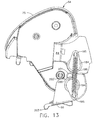
- FIGURE 13 shows the cartridge partially inserted into the operating position.
- actuators or posts 201 on the cartridge 54 which can touch cam faces 202 on the member 66.
- the member 66 continues to be held in the open position by the spring 199.
- the actuators 201 cam the member 66 until the member 66 has rotated overcenter with respect to the centerline 200.
- the spring 199 urges the member 66 to the operating position. Accordingly, the spring 199 can alternately hold the member 66 in either the open position ( FIGURE 12 ) or in the closed position ( FIGURE 14 ).
- the operating position is also shown in FIGURES 2 through 4 and 22 for example.
- the posts or pins 201 act on cam surfaces 202' to drive the member 66 to its open position.
- the member 66 has projections 203 received in pockets 204 in the plate 116, one of which is shown in FIGURE 4 .
- the actuators 201 cooperating with cam faces 202 are sufficient to bring the holder 66 to its operating position when the cartridge is inserted fully, without the aid of the spring 199.
- the actuators 201 cooperating with cam faces 202' are sufficient to bring the holder 66 to its open position during removal of the cartridge 54.
- the spring 199 is useful is bring the holder 66 either into its fully open position or its fully closed position and hold the holder in either position.
- FIGURES 15 , 16A and 16B show that the cartridge 54 has a frame or housing 75 which can have frame or housing sections 206 and 207.
- the frame sections 206 and 207 are preferably of one-piece construction.
- the frame section 206 has a supply roll mounting portion 208 and a take-up roll mounting portion 209.
- the supply roll mounting portion 208 can have an arcuate frame wall 208'.
- the arcuate shape is preferred for strength and to more fully enclose the supply roll SR, however, more open shapes can be provided instead.
- the wall 208' is integral with a side wall 210 and has a post 211 which rotatably mounts a shaft 211'.
- the position of the shaft 211' which extends beyond the post 211 receives an annular, axially compressible and radially expandable elastomeric brake sleeve 212.
- the side wall 210 is connected to a side wall 213 of the take-up roll mounting portion 209.
- the section 206 can have an arcuate frame wall 214 if desired and post 215 joined to the wall 213.
- the post 215 rotatably mounts a shaft 215'.
- the posts 211 and 215 are generally parallel.
- a rotatable spindle 216 can grip the take-up roll core 78' to wind up the take-up roll TR and thereby advance the ink ribbon I.
- the spindle 216 is coupled to a driver 217 ( FIGURE 10 ) when the cartridge 54 is in the operating position in the printer 50.
- a clutch 245 ( FIGURE 17 ) attempts to advance the ink ribbon I faster than the ink ribbon I is advanced by the platen roll 68 to maintain tension in the ink ribbon I between the platen roll 68 and the take-up roll TR.
- the portion 206 of the cartridge frame is shown to have a tear edge portion 218 of a tear edge 219 ( FIGURE 15 for example).
- the frame section 207 includes a side wall 220 joined to a side wall 221.
- the section 207 can also have arcuate frame walls 222 and 223 joined to the respective side walls 220 and 221.
- the posts 224 and 225 are joined to the side wall 220 and a post 226 is joined to the side wall 221.
- the post 224 is axially aligned with the spindle 216
- the post 225 is axially aligned with the post 215,
- the post 226 is axially aligned with the post 211.
- the shaft 215' is connected to a handle 227 ( FIGURE 15 ) which is detentable in two alternative positions.
- the shaft 211' is connected to a handle 228.
- the shaft 215' has a non-circular projection 229 and the shaft 211' has a non-circular projection 230.
- the projection 229 can be received in a non-circular hole 231 in the post 225 and the projection 230 can be received in a non-circular hole 232.
- the projections 229 and 230 are in the hollows of posts 225 and 226 out of alignment with holes 231 and 232.
- the projections 229 and 230 extend beyond the holes 231 and 232 into hollow interior space in the posts 225 and 226.
- the frame section 207 has a tear edge portion 241 aligned with the tear edge potion 218 of the tear edge when the frame sections 206 and 207 are assembled to provide a tear edge 219 that extends at least as long as the widest web W between gripper arms 63.
- the walls 214 and 222 terminate at respective tear edge portions 218 and 241.
- the tear edge 219 can be used to tear off the web C or the carrier web W in the strip mode in which the web C or the web W is fed out through the exit opening 70.
- the carrier web W passes about the delaminator 69 and between the platen roll 68 and the back-up roll 71 and from there the web W passes out of the exit opening 72.
- Lower edge of the toggle member 74 also has a tear edge 74' ( FIGURE 3 for example) for tearing of excess carrier web W that extends beyond the exit opening 72.
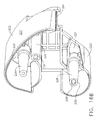
- FIGURE 17 there is shown the drive mechanism 81 which is essentially the same as the drive mechanism in U. S. Patent 5,597,249 , except for example a guide slot 260 ( FIGURE 18 ) in the mounting plate 242'.
- FIGURE 17 shows the electric motor 242 mounted on a stand off 243.
- Gearing generally indicated at 244 drives the toothed driver 217 ( FIGURE 5 ) through a clutch 245 which may be of the wrapped-spring type if desired.
- the gearing 244 includes a compound gear 246 which includes a gear 247 rigidly coaxially connected to a gear 248.
- the gear 247 meshes with a pinion on the motor shaft (not shown).
- the pinion on the motor shaft also drives a compound gear 249 which drives a gear 249' and in turn a gear 250 which is part of the clutch 245.
- FIGURE 18 shows the mounting plate 242' as having an open-ended slot 260 which receives the bearing socket 117' and the outboard bearing 119.
- the slot 260 thus captures the bearing socket 117' and the bearing 119 and promotes proper meshing of the gear 95 and the gear 248.
- the housing section 169 has an open-ended slot 169' ( FIGURE 10 ) which is larger than the slot 260 so that neither the shaft 94 nor socket 117 controls the alignment of the gear 95 with the gear 248. It is rather the slot 260 alone which controls the meshing of the gears 95 and 248. It is noted that when the door 53 is closed the socket portion 117' preferably bottoms in the slot 260, as shown.
- the slot 260 has a converging entry 261 with tapers 262 at both sides adjacent the opening in the slot 260 to guide the socket portion 117' and the bearing 119 into the slot 260 when the door 53 is moved to the closed position.
- the print head assembly 85 which may include support or mounting plate 89 having a socket 262 for receiving the post 86 ( FIGURE 3 for example).
- the socket 262 and the post 86 enable the support 89 to pivot or gimbal to enable the print head 67 to accommodate to the platen roll 68.
- the print head 67 is mounted on the underside of a metal plate or heat sink 67' which helps dissipate heat from the print head 67.
- the support 89 is shown to have preferably three holes 263, 264 and 265.
- the holes 263, 264 and 265 are aligned with respective threaded holes 266, 267 and 268 in the heat sink 67'.
- the ribbon guide 79 which may be in the form of a guide plate 271 having a generally planar or plate-like portion 271' having three holes 272, 273 and 274.
- the hole 272 is round and makes a rotatable fit around a boss 263' surrounding the hole 263.
- the hole 273 is oversize with respect to the boss 264' and receives the boss 264' that surrounds hole 264.
- the hole 274 is elongate and receives the boss 265' which surrounds the hole 265.
- a screw 270 passes through holes 272 and 263 and is threadably received in the hole 266.
- a screw 270 passes through holes 273 and 264 and is threadably received in the hole 267, and a screw 270 passes through the holes 274 and 265 and is threadably received in the hole 268.
- the guide 79 has a curved portion 275 which is at least as wide as the ink ribbon I and is joined to the planar portion 271'.
- the guide 79 also includes a flange 271" with a threaded hole 276 to receive a threaded shank 277 of an adjusting screw 278.
- the screw 278 can preferably have a socketed head 279 with an Allen socket to receive an Allen wrench (not shown).
- the head 279 is received in a socket 280 molded integrally with the support 89.
- a groove 281 aligned with the head 279 in the socket 280 serves as a guide for the Allen wrench.
- the groove 281 is open at both ends and one end opens into the socket 280.
- the screw 278 is able to rotate but is not able to translate. Rotation of the screw 278 will cause the guide 79 to pivot about the boss or pivot 263' to adjust the guide 79.
- FIGURE 22 shows that the groove 281 shown in FIGURE 20 comprises only one-half the opening 282 through which an Allen wrench can extend.
- the other half of the opening 282 is comprised of an end wall 281' in the support 84.
- the opening 282 is aligned with an access opening 283 in the support 84. While the printer of U.S.
- Patent 5,597,249 had a guide which was adjustable it was not possible to adjust the guide while the printer was advancing the record member web or the ink ribbon. It was necessary to stop operation of the printer, adjust the guide, restart the printer and possibly re-adjust the guide again, and so on until adjustment and wrinkle-free advance of the ink ribbon was attained.
- the web C and the ink ribbon I can be advanced upon rotation of the platen roll, and the guide 79 can be adjusted while the ink ribbon I is advancing.
- the support or mounting member 89 includes a pair of depending flanges 284, each having a locating or guide slot 285 ( FIGURE 19 ).
- Springs 286 FIGURE 20
- FIGURE 9 shows pairs of stops 117a and 118a.
- the support 84 has a pair of stop faces 84a and 84b which abut the respective stops 117a and 118a when the support 84 is in the operating position.
- FIGURE 23 there is shown one of the resilient, elastomeric bumpers 52', in particular a foot which can be attached to the housing section 52 easily during manufacture and which can be removed if desired.
- the four feet 52' are shown taking FIGURES 1 and 2 together.
- the feet 52' are preferably identical as is preferred so only one is described in detail.
- the foot 52' has a body 52" which is external to the housing section 52 and preferably has a triangular shape in horizontal section and the foot 52' also has a triangular shape in vertical section.
- the foot 52' is intended to be attached to the outside of the housing section 52, but part of the foot 52' is internal to the housing section 52.
- the housing section 52 has a pair of spaced internal ribs 300 which straddle an opening or slot 301.
- the foot 52' has an elongate portion 302 received in the slot 301 and a pair of flanges 303 which contact inner faces 300' of the ribs 300.
- the flanges 303 capture the foot 52'.
- the bumper 52' has a projection 304 which cooperates with a projection 305 on the housing section 52 ( FIGURE 26 ) to prevent retrograde movement of the foot 52' out of the slot 301.
- FIGURE 27 there is shown a portion of the housing section 52 with slots 306 and 307 by which a front bumper 55 can be attached.
- the slot 306 is open-ended, while the slot 307 has closed ends 308 and 309.
- the slot 306 may have a constant width as shown, and the slot 307 has a wide portion 310 and a narrow portion 311 joined by a converging portion 312.
- FIGURE 28 shows the bumper 55 as having an arcuate shape to fit the outer profile of the arcuate-shaped corner portion 313 ( FIGURE 27 ) of the housing section 52.
- the underside of the bumper 55 that is, the portion at the inner side of the bumper 55 has two flexible, cantilevered projections 314 and 315 having respective flanges 316 and 317.
- the projection 315 is inserted into the wide slot portion 307.
- the projection 314 is slightly beyond the open end of the slot 306.
- the bumper 55 is slid along the arcuate portion 313 so that a relatively wide neck 318 of the projection 314 enters the slot 306 and a relatively narrow neck 319 of the projection 315 starts moving along the converging slot portion 312.
- the neck 319 reaches the slot end 309 ( FIGURE 27 ) the bumper 55 is in place and the flanges 316 and 317 are against an inner surface 313' of the housing 52 adjacent slot 306 and slot portion 311, respectively.
- the resilient elastomeric material of the bumper 55 frictionally grips the arcuate portion 313 adjacent the slots 306 and 307, partly due to the close fit between the necks 318 and 319 and upper sides 316' and 317' and the underside 313' of the arcuate portion 313.
- FIGURE 32 shows the bumper 57 with preferably two substantially identical, spaced, cantilevered, internal projections 325, each including a neck 326 and a flange 327 with a face 328.
- the face 328 overhangs a face 329 on the bumper body 57'.
- the housing section 52 has a curved external corner portion 330 protected by the bumper 57.
- the bumper body 57' has a flange 331 which covers the left side of the housing section 52.
- the remainder of the body 57' covers the top of the housing section 52.
- the housing section 52 has slots 332 each of which as an enlarged slot portion 333 and a reduced slot portion 334.
- the projections 325 are lined up with respective enlarged slot portions 333 and pushed inwardly until the faces 328 are in line with the inside surface 335 of wall 336 of the housing section 52. Then the bumper 57 is slid downwardly and rearwardly as viewed in FIGURE 32 until the necks 326 abut against bottoms 337 of the slots 332, whereby the bumper 57 is captive in the slots 332 in the housing section 52 with the housing wall 336 between faces 328 and 329.
- FIGURES 33 through 36 there is shown an arrangement by which a fan-folded web of a composite web C or a web of tags (not shown) can be utilized by the printer 50.
- the lower portion of the door 53 is provided with a converging throat 340 provided by guide surfaces 340' which provide entry into the space 64 normally used to contain the record member supply roll R'.
- the space 64 is bounded by surfaces 66a, 66b and 66c ( FIGURE 2 ). From there the composite web C, or the web of tags, as the case may be, is guided by a guide generally indicated at 341 and from there the web C is guided to between the print head 67 and the platen roll 68.
- FIGURE 34 shows the guide 341 as including a preferably tubular shaft or tube 342 and preferably identical side edge or side guides 343.
- the shaft 342 has a certain outside periphery or surface at 342' with a certain diameter and one or more integral, radially outwardly extending ribs or web-contacting guide members 344.
- the set of members 344 is preferably midway between terminal ends 345 and 346 of the shaft 342.
- the shaft 342 has diametrically opposed, longitudinally extending grooves 347.
- the grooves 347 in turn contain laterally extending closely spaced ridges 348 best shown in FIGURES 35 and 36 disposed on opposite sides of the guide members 344.
- the outer surface 342' also contains peripherally extending graduations 349 at preferably equally spaced or selected intervals at both sides of the guide members 344.
- Side guides 343 have disc-shaped members 350 and an annular or tubular hub 351.
- the hub 351 has opposed slots 352 into which at least one and preferably two diametrically opposed spring fingers or projections 353 extend.
- the spring fingers 353 are cantilevered to the disc 350 and each spring finger 353 has a tooth 353' to engage the shaft 342 between adjacent ridges 348 in the respective groove 347.
- the spring fingers 353 may have a slight inward inclination toward the tube 342 in the asmolded state.
- the spring fingers 353 preferably do not project outwardly beyond the outer periphery of the hub 351.
- the outside diameters of the hubs 351 and the guide members 344 are preferably the same or essentially the same so that side edges of the web C are guided by the discs 350 and the marginal sides edges of the web C are supported by the hubs 351 and the guide members 344. Not only is the web C guided but the web C is well supported so that any tendency of the web C to warp or meander is eliminated.
- end portions 354 of the shaft 342 receive the hubs 92 of the roll mounting members 91.
- the roll mounting members 91 are manually spread apart and then the shaft 342 is aligned with the hubs 92 and released so the shaft 342 is mounted as shown in FIGURE 35 center-justified with respect to the print head 67.
- the shaft 342 is center-justified along centerline CL midway between terminal ends 345 of the shaft 342, the user may position the side guides 343 at equal distances from the ends 345 in order to achieve such center-justification.
- the graduations 349 are provided so that the user can readily position both side guides 343 at equal distances from the centerline CL, that is, at equal distances from the terminal ends 345 and 346.
- the graduations 349 may be grooves as shown or slightly raised or they may be printed, however, grooves as shown or ridges are preferred because they are molded-in and do not require a secondary operation to create them. If the graduations 349 are raised, the inside diameters of the hubs 351 need to be sized accordingly.
- the entire shaft 342 including its features such a guide members 344 is of one-piece molded plastics construction.
- the side guides 343 are assembled with the discs 350 outboard of the hubs 351. This enables the guide 341 to be used with the widest webs and some narrower webs C.
- the side guides 343 can be turned around or reversed so that the web C, shown in phantom lines, can be used to guide a narrow web C.
- the entire printer is composed of molded plastics material except for the peel roller 69, the guide 79, shafts 94, 105 and 111, springs 149, 199 and 286 bearings 119, 119' 120 and 120', the display 60, the print head 67, the heat sink 67', the motor 242 the clutch 245 and its gear 244, the batteries 80', contacts, electronics and various screws.
- the brake 212 and the outer part of the platen roll 68 are comprised of resilient elastomeric material, as are all the bumpers 52', 55, 56, 57 and 58.
- housing sections 52, 53 and 54 are sometimes referred to respectively as first, second and third housing sections, there is no intention to thereby limit the invention, or signify importance of one housing section over any other housing section.
- FIGURES 37 through 40 is the same as the embodiment of FIGURES 1 through 36 except as otherwise indicated. Accordingly, the same reference characters as used to designate components having the same construction for the sake of clarity.
- FIGURES 37 through 40 show an arm 184' with an integrally formed flange or support 184" which may extend perpendicular to the arm 184' as shown.
- the arm 184' is essentially the same in shape as the arm 184, but the arm 184' is modified to mount the flange 184".
- a tension spring 199' is similar to the spring 199, but the spring 199' is connected to the connector 185, passes partially around and against the flange 184" and is connected to the connector 195.
- the support 84 is continuously urged clockwise by the spring 199' and the guide or holder 66 is continuously urged counterclockwise by the spring 199'.
- FIGURE 38 shows one of the actuators 201 as just touching the surface 202 and consequently the guide or holder 66 has not moved from its FIGURE 37 position.
- the actuators 201 push against surfaces 202 and move, and in particular pivot, the guide or holder 66 clockwise against the counterclockwise urging force of the spring 199' to bring the guide or holder 66 to the intermediate position shown in FIGURE 39 .
- the guide or holder 66 will be cammed by the housing section 53 acting against the projection 203 until the projection 203 descends into the pocket 204 as shown in FIGURE 4 , thereby bringing the guide or holder 66 to the closed or operating position shown in FIGURES 4 and 40 .
Abstract
Description
- The disclosed embodiments relate to printers and methods of making printers.
- The following prior art is made of record:
U.S. Patent 5,160,205 ;U.S. Patent 5,486,259 ;U.S. Patent 5,570,121 ;U.S. Patent 5,588,756 ;U.S. Patent 5,708,462 ;U.S. Patent 5,785,442 ;U.S. Patent 5,597,249 ;U.S. Patent 6,241,407 ; andU.S. Patent 6,609,844 . - In a specific embodiment, a printer includes a housing, a support mounted on the housing, a print head mounted on the support and capable of printing on a web of record members, an ink ribbon cartridge received on the support, a guide for the web continuously spring-urged into a non-operating position, the guide being movable between the non-operating position and an operating position through an intermediate position, the ink ribbon cartridge being movable to move the guide from the non-operating position to the intermediate position against the spring-urging, and the housing having a movable housing section capable of moving the guide from the intermediate position to the operating position against the spring-urging. It is preferred that the support is movably mounted between operating and non-operating positions and that the support is spring-urged to its non-operating position. It is preferred that the printer include a platen roll, wherein support is cooperable with the platen roll in its operating position and is free of the platen roll in its non-operating position. It is preferred that a spring is connected to the support and the guide for accomplishing the spring-urging.
- In a specific embodiment, a printer includes a housing, a support mounted on the housing, a print head mounted on the support and capable of printing on a web of record members, an ink ribbon cartridge received on the support, a holder continuously spring-urged into a non-operating position, a sensor and/or a light source on the holder, the holder being movable between the non-operating position and an operating position through an intermediate position, the ink ribbon cartridge being movable to move the holder from the non-operating position to the intermediate position against the spring-urging, and the housing having a movable housing section capable of moving the holder from the intermediate position to the operating position against the spring-urging. It is preferred that the support is movably mounted between operating and non-operating position and that the support is spring-urged to its non-operating position. It is preferred that the printer include a platen roll, and that the support is cooperable with the platen roll in its operating position and is free of the platen roll in its non-operating position. It is preferred that a spring is connected to the support and the guide for accomplishing the spring-urging.
- In a specific embodiment, a printer includes a support movably mounted on the housing between operating and non-operating positions, the support being continuously spring-urged to its non-operating position, a platen roll mounted on the housing, the support being located with respect to the platen roll in the operating position, and a print head yieldably mounted to the support. It is preferred that there is at least one spring for spring-urging the support. It is preferred that the housing includes a door movable between open and closed positions, and a latch mounted on the door to move the support to the operating positing against the spring-urging to the support. It is preferred that the latch is comprised of a toggle mechanism and that the toggle mechanism grips the ink ribbon cartridge. It is preferred that the print head is spring-urged by at least one spring, and wherein the spring is partially compressed when the support is in its operating position.
- It is a feature of the disclosed embodiments to provide an improved printer and in particular a portable printer which is lightweight, compact, durable, user-friendly, easy to load and unload of label and tag supplies in a roll and fan-fold form and an ink ribbon cartridge, and has minimal parts almost all of which are of molded plastics construction. Various other features will be readily evident to persons skilled in the art by reference to the drawings and the detailed description that follow.
-
-
FIGURE 1 is a pictorial view of a printer in accordance with an embodiment; -
FIGURE 2 is a sectional view through the printer taken along line 2-2 ofFIG 1 ; -
FIGURE 3 is an enlarged sectional view showing the upper portion of the printer; -
FIGURE 4 is an enlarged sectional view of the printer along a different line than inFIGURES 2 and3 ; -
FIGURE 5 is a pictorial view of the printer with the front door open and with an ink ribbon cartridge exploded away; -
FIGURE 6 is a sectional view of the printer with its front door open and the ink ribbon cartridge exploded away; -
FIGURE 7 is an exploded pictorial view of the front door and a toggle latch mechanism on the door; -
FIGURE 8 is an assembled pictorial view of the front door on which a platen roll, a delaminator, a tear edge, a toggle latch mechanism and a roll mounting assembly are mounted; -
FIGURE 9 is an exploded pictorial view of a portion of the printer showing a portion of the door, the roll mounting assembly and the platen roll; -
FIGURE 10 is a rotated, exploded, pictorial view of a portion of the printer; -
FIGURE 11 is a rotated, exploded, pictorial view of another portion of the printer; -
FIGURE 12 is an exploded elevational view showing the printer in a position to be capable of receiving an ink ribbon cartridge; -
FIGURE 12A is an enlarged sectional view of a portion of the printer shown inFIGURE 12 ; -
FIGURE 13 is a side elevational view of a portion of the printer with the ink ribbon cartridge partly received in the printer; -
FIGURE 14 is a view similar toFIGURE 13 , but showing the ink ribbon cartridge fully received in its operating position in the printer; -
FIGURE 15 is a pictorial view of the ink ribbon cartridge; -
FIGURE 16A is a pictorial view of one portion of the ink ribbon cartridge; -
FIGURE 16B is a pictorial view of another portion of the ink ribbon cartridge; -
FIGURE 17 is a pictorial view of a portion of the printer showing the ink ribbon cartridge latched in position and broken away to expose the drive mechanism for the ink ribbon cartridge and the platen roll; -
FIGURE 18 is an enlarged, partly sectional view showing the manner in which the platen gear is held in position with respect to the driving gear; -
FIGURE 19 is a pictorial view showing the manner in which the print head assembly is mounted; -
FIGURE 20 is an exploded pictorial view of the print head assembly; -
FIGURE 21 is a bottom plan view of the print head assembly; -
FIGURE 22 is a sectional pictorial view through the upper portion of the printer; -
FIGURE 23 is a pictorial view of one of the bumpers which also serves as a foot for the printer; -
FIGURE 24 is a pictorial view showing the bumper assembled onto the main printer housing; -
FIGURE 25 is a sectional view showing a portion of the main printer housing; -
FIGURE 26 is a sectional view showing the manner in which the bumper or foot is held captive in the main printer housing; -
FIGURE 27 is a pictorial view showing a slot in the front portion of the main housing into which a bumper can be inserted; -
FIGURE 28 is an exploded pictorial view showing the front portion of the housing depicted inFIGURE 27 into which a bumper can be inserted; -
FIGURE 29 is a pictorial view of the bumper shown inFIGURE 28 ; -
FIGURE 30 is a sectional view taken along line 30-30 ofFIGURE 29 ; -
FIGURE 31 is a sectional view taken along line 31-31 ofFIGURE 29 ; -
FIGURE 32 is an exploded pictorial view of a bumper at the rear portion of the housing; -
FIGURE 33 is a sectional view of the lower portion of the printer with a guide for guiding a record member web in a fan-fold mode; -
FIGURE 34 is an exploded pictorial view of the guide also shown inFIGURE 33 ; -
FIGURE 35 is a sectional view of the guide held in a label roll holder; -
FIGURE 36 is an enlarged sectional view of a portion of the guide depicting an alternative way in which side edge guide members may be mounted; -
FIGURE 37 is an exploded side elevational view similar toFIGURE 12 , but showing another embodiment of the invention; -
FIGURE 38 is a side elevational view similar toFIGURE 13 , but showing the other embodiment also shown inFIGURE 37 wherein a guide or holder is held in an open position; -
FIGURE 39 is a side elevational view similar toFIGURE 14 , but showing the other embodiment with the guide or holder is an intermediate position; and -
FIGURE 40 is a side elevational view similar toFIGURE 14 , but showing the other embodiment with the guide or holder in a closed or operating position. - With reference initially to
FIGURE 1 , there is shown a printer generally indicated at 50 having a housing generally indicated at 51. Theprinter 50 is portable and can be easily carried by a strap (not shown) on opposed posts 50' (only one of which is shown) or used on a table or other surface. Theprinter 50 is lightweight and has a small footprint. Thehousing 51 includes amain housing section 52, anotherhousing section 53 which is movable relative to thehousing section 52 and athird housing section 54. Thehousing sections housing section 52 is only to distinguish it from thehousing section 53, not to signify dominant importance. Thehousing section 52 may stand on a horizontal surface such as a table and be supported atbumpers 52' in the form of preferably identical feet at the four corners of thehousing 51. Thehousing section 54 preferably takes the form of an ink ribbon cartridge. Thehousing section 52 also hasfront bumpers rear bumpers bumpers bumper 55 is a left-hand version and thebumper 56 is a right-hand version. Likewise, thebumpers bumper 57 is a left-hand version and thebumper 58 is a right-hand version. Thebumpers main housing section 52 and extend outwardly so that in the event theprinter 50 falls on a flat surface one or more of the bumpers will impact the flat surface and not any part of thehousing 51, except for the posts 50'. The posts 50' may project outwardly beyond thebumpers housing section 52 where the posts 50' are mounted are made thicker. The front of theprinter 50 is designated F and the rear of theprinter 50 is designated R. The front F also includes adisplay 60 and a keypad orkeys 61 to control various printer functions. Thehousing sections toggle mechanism 62 which has spacedgripper arms 63. - With reference to
FIGURES 2 and3 , there are shown thehousing sections space 64 for reception of a roll R' of a composite web C of record members. The record members can comprise paper labels L releasably adhered to a carrier web W as illustrated, or they can comprise tags or forms. The composite web C for example can pass from the roll R' to between aguide wall 65 and a guide andholder member 66. Themember 66 has a dual purpose of guiding the web C and of mounting part of a sensor system S including a light source 66' (FIGURE 3 ) and a light source/sensor 66". The light source 66' can be a light emitting diode for example OPR5200 and the light source sensor can be Type OPR5005, both sold by Optek Technology, Inc. Carrollton, Texas. The light from the light source 66' can pass through an aperture or notch in the web C or through the web W between spaced labels L and can be detected by the sensor of the light source/sensor 66" for web registration purposes or the light source/sensor 66" can detect edges between spaced adjacent labels L. The light source/sensor 66" can also detect registration marks on the underside of the web C by shining light from the light source portion of the light source/sensor 66" onto the underside of the web C and detecting the registration mark with the sensor portion of the light source/sensor 66". It is preferred to mount the light source 66' and the light source/sensor 66" as shown and described however, a different arrangement can be used, for example, a sensor can be mounted on themember 66 at the location where the light source 66' is disposed and the light source for that sensor can be located where the light source/sensor 66" is disposed. Alternatively, the positions of the light source/sensor 66" and the light source 66' can be reversed. Accordingly, because themember 66 acts as a guide it is properly termed a guide or guide member or a member, however, because themember 66 serves as a mount for part of the sensing system S it is properly called a mounting member or member. From betweenguides thermal print head 67 and aplaten roll 68. From there the carrier web W passes partly around adelaminator 69 and the printed label L passes through an exit opening 70 (FIGURE 2 ) and along an exit path between the gripper arms 63 (FIGURE 1 ). After passing about thedelaminator 69 at a sharp angle, the carrier web W passes between and into contact with theplaten roll 68 and a back-up orpressure roll 71. From there the web W passes through anexit opening 72 betweentoggle members - The housing section or specifically the ink ribbon cartridge or
cassette 54 is comprised of a cartridge frame or housing generally indicated at 75. Theframe 75 includes an ink ribbonsupply frame section 76 and a spentink ribbon section 77 joined to each other. Theframe section 76 mounts asupply roll spindle 78 about which an ink ribbon supply roll SR is wound. Ink ribbon I passes from the supply roll SR over the composite web C to the nip between theprint head 67 on the one side and the web C and theplaten roll 68 on the other side. From there the spent ink ribbon I passes about aguide 79 preferably in the form of a guide plate and from there the spent ink ribbon I passes to the take-up roll TR where the spent ink ribbon I is accumulated. As theprinter 50 operates and the ink ribbon I is advanced from the supply roll SR to the take-up roll TR, the size of the take-up roll TR grows until the supply roll SR is exhausted and the take-up roll TR is full as indicated by the circular phantom line PL. The take-up roll TR is wound on a take-up spindle 78'. - The section taken to create
FIGURE 2 shows thebattery pack 80 including preferably a plurality of batteries 80' used to power the circuitry (not shown) and the drive mechanism or drive assembly 81 (FIGURE 17 ). Thebattery pack 80 is received in acompartment 82 in thehousing section 52. -
FIGURE 2 also shows one of the two axially alignedpivots 83 for thehousing section 53. Thehousing section 53 which functions as a door and, in particular, a front door is movable about thepivots 83 between a closed position shown inFIGURES 1 and2 , for example, and an open position shown inFIGURES 5 and6 . -
FIGURE 3 shows the upper portion ofFIGURE 2 on a larger scale.FIGURES 2 and3 show that thehousing section 52 has a cantileveredsupport 84 which mounts aprint head assembly 85 and is capable of removably receiving and supporting theink ribbon cartridge 54. Thesupport 84 has aprojection 86 about which theprint head assembly 85 is pivotal or gimbaled. -
FIGURE 4 is a view taken through one of thegripper arms 63 and shows how atooth 87 engages a gripper or grippedsurface 88 on thecartridge 54.FIGURE 4 also shows the manner in which theprint head assembly 85 and in particular itsprint head support 89 can locate on thebearing 120 for theplaten roll 68. - With reference to
FIGURE 5 , the housing section ordoor 53 is shown to mount a label roll holder generally indicated at 90. Thelabel roll holder 90 can be any suitable structure to mount a label or tag roll, however, it is preferred that theholder 90 haveholder members 91 engageable with the label or tag roll R' and which are movable relatively toward and away from each other in unison to center-justify the label roll R' with respect to the center of theelongate print head 67. Theholder members 91 are preferably identical and are shown to be in the form of discs have having projections or hubs orhub portions 92 capable of fitting preferably with a close fit into the inside of acore 93 of the label roll R'. Thedoor 53 also rotatably mounts theplaten roll 68 which has aplaten shaft 94 and agear 95 secured to theshaft 94. - The
gripper arms 63 are spaced outboard of the exit path 70 (FIGURES 1 and2 ) along which a record member, for example, label L exits theprinter 50. It is also apparent fromFIGURE 5 that theprinter 50 is easy to load by moving theholder members 91 apart and allowing theprojections 92 to enter into the inside of thecore 93. The user may strip several labels L from the carrier web W and lay the spent web W across theplaten roll 68 and then pass the web W partially around thedelaminator 69 and insert the web W between theplaten roll 68 and thepressure roll 71 and out throughexit opening 72. Then the user can move thedoor 53 to its closed position as shown inFIGURE 1 for example and may tug on the web W which is beyond theexit opening 72 to remove any slack from the web W. It is evident from the figures such asFIGURE 1 that theexit openings gripper arms 63 from the outside of theprinter 50. -
FIGURE 5 also shows theink ribbon cartridge 54 ready to be inserted into thehousing section 52 in the direction ofarrow 100 and onto thesupport 84. - With reference to
FIGURE 7 , there is shown the outer panel orplate 101 of thedoor 53 and thetoggle mechanism 62. Thepanel 101 mounts thedelaminator 69 shown to take the form of a roller orpeel roller 102. Thedelaminator 69 can alternatively be a peel plate (not shown), however, apeel roller 102 is a preferred form of a delaminator. The preferably one-piece panel orplate 101 has a pair of space C-shapedsockets 103 which capture end portions of theroller 102. Thepanel 101 has a pair of alignedholes 104 which mount ashaft 105. Oneend portion 106 of theshaft 105 is knurled and is press-fitted into thehole 104 at the left side of thepanel 101. Theshaft 105 passes through a through-hole 107 in the preferably one-piece toggle member 73 to mount thetoggle member 73 for pivotal movement. The preferably one-piece toggle member 74 is shown to include a bar ortransverse connector 108 that connects thegripper members 63 to each other. Theteeth 87 are located in one direction, for example, above theconnector 108 and extensions orshaft mounting members 109 extend in the other direction or below theconnector 108. Theconnector 108 preferably rigidly connects the onegripper member 63 to theother gripper member 63 and connects the onemember 109 to theother member 109. Themembers 109 have alignedholes 110 to receive ashaft 111. Thetoggle member 73 is disposed betweengripper arms 63 and theshaft 111 passes through a hole 107' in thetoggle member 73. Anend portion 112 of theshaft 111 is knurled. Theend portion 112 is press-fitted into thehole 110 of themember 109 at the left side of thetoggle member 174. In order to releasegripper members 63 so thatteeth 87 no longer engage the gripped surfaces 88 on thecartridge 54 and so that thecartridge 54 can be removed from the remainder of theprinter 50, the user can insert a finger beneath a handle 113 (FIGURES 2 ,3 ,4 and7 ) and pull thetoggle member 73 to move clockwise about theshaft 105. As thetoggle member 73 starts to move clockwise inFIGURE 4 for example about theshaft 105, thegripper teeth 87 exert increased force against the gripped surfaces 88. As thetoggle member 73 continues to move clockwise even further, then theshaft 111 moves from the right side of acenterline 114 to the left side of thecenterline 114. InFIGURE 4 , theshaft 111 is overcenter with respect to thecenterline 114 in one direction at a latched condition or state. When theshaft 111 has moved to the left of thecenterline 114, the shaft is overcenter in the other direction which causes loosening of thegripper teeth 87 from the gripped surfaces 88 until thegripper arms 63 are free of thecartridge 54. Now theink ribbon cartridge 54, thesupport 84 and theprint head 85 can be manually pivoted slightly clockwise as viewed inFIGURE 4 to disengageguide slots 285 from bearings 119' and 120'. Thedoor 53 can now be moved to its open position with respect to thehousing section 52. When thedoor 53 is moved to the closed position, theteeth 87 are at a position over and spaced from the gripped surfaces 88. By pushing on thehandle 113, thetoggle member 73 is pivoted counterclockwise (FIGURES 4 and7 for example) to bring theshaft 111 and thegripper members 63 to the closed position shown inFIGURE 4 for example, and thus theshaft 111 has moved to the right of thecenterline 114.FIGURES 2 ,7 and8 show thepanel 101 as having arecess 115 to provide ready finger access by the user to the underside of thehandle 113. Thepanel 101 can also be provided with alogo plate 116. Thetoggle member 74 also has an on-demand sensor S' (FIGURE 8 ) which can sense the presence of a label L at theexit opening 70. - With reference to
FIGURE 9 , there is shown an inner panel or plate generally indicated at 116 attached to the panel orplate 101 by screws 116'. The preferably one-piece panel 116 has a pair of aligned C-shapedsockets Ball bearings sockets respective sockets shaft 94 has oneend portion 121 received in theball bearings 119 and 119' and anotherend portion 122 received in theball bearings 120 and 120'. An E-ring 120" keeps the bearing 120 on theend portion 122. Thegear 95 is press-fitted onto theend portion 121 and holds the bearing 119 in place. - The
label roll holder 90 includes a pair ofidentical slides respective arms 125 and 126. Eacharm 125 and 126 has ahole 127 into which anintegral connector 128 on thedisc 91 is received. Theconnectors 128 enable thediscs 91 to rotate relative to theirrespective arms 125 and 126. - Each
arm 125 and 126 has an outwardly extendingboss 129 having a hole 129'.Handles 130 preferably in the form of washers are held onto thebosses 129 spaced from the outer surfaces of therespective arms 125 and 126 byscrews 131. Either handle 130 enables the user to insert a fingernail between thehandle 130 and the outer surface of therespective arm 125 or 126 and pull outwardly, thereby causing theroll mounting members 91 to move apart should it be desired, for example, to remove a spentcore 93 or a guide 341 (FIGURE 35 for example). Alternatively, either handle 130 can be grasped between two fingers to spread theholder members 125 and 126 apart. It is noted that when oneholder member 125 or 126 is moved outwardly away from theother holder member 126 or 125, a rack and pinion mechanism generally indicated at 132 moves theother holder member 126 or 125. - The
panel 116 has a pair ofparallel slots respective flanges slide 123 has a pair of L-shapedmembers 137 withflanges 138. Themembers 137 extend through slots 137' bounded by flanges 138' havingend surfaces 138". Theflanges 138 contact the end surfaces 138". Likewise, theslide 124 has a pair of L-shapedmembers 139 withflanges 140, which are received in similar slots (not shown) that are mirror images of the slots 137'. Themembers 137 are assembled throughrespective slots 138s. - The
slides straight gears panel 116 has an integrally moldedpin 145 on which is gear orpinion 146 can be rotatably mounted. Thegear 146 is coupled to and can mesh withracks slide 123 has apost 147. Theslide 124 was molded with a post (not shown) like thepost 147 which can be cut off before assembly of theprinter 50. Thepinion 146 assures that theslides arms 125 and 126 and thediscs 91 at equal distances with respect to the centerline between the ends of theelongate print head 67. Atension spring 149 is hooked onto thepost 147 and onto apost 148 on thepanel 116. Thespring 149 is under tension and acts to urge theslides respective arms 125 and 126 toward each other. - A keeper or
plate 150 slidably contacts the end surface 135'.Screws 151 pass through theplate 150 and are received inbosses 152. Likewise a keeper orplate 153 slidably contacts the end surface 136'.Screws 154 pass through theplate 153 and are received by bosses 152'. Thebosses 152, thepost 147 and theracks slot 133 and the bosses 152' and theracks slot 134. A tang or stop 155 on theplate 150 projects into theslot 133 and can contact end 156 of theslot 133 to prevent themembers 137 from aligning with theslot 138s and to thereby prevent themembers 137 from coming out of the slot 137' during use. A tang or stop 157 on theplate 153 projects into theslot 134 and can contactend wall 158 to preventmembers 139 from coming out of theirrespective slot 134 during use. - The
panel 116 also has apost 159 for mounting agear 160 which is coupled to and can mesh with therack 144. A plate or slide 161 guided in aslot 162 has atooth 163 which can engage a tooth of thegear 160 below the axis of rotation of thegear 160. Theslide 161 is normally urged to the right as shown inFIGURE 9 by a compression spring 163' that abuts against and is captive between aboss 164 and asurface 165 on thepanel 116. Anarm 166 joined to theslide 161 has acam surface 167 used to move the slide to the left as viewed inFIGURE 9 . When thedoor 53 is being closed, thecam surface 167 contacts thehousing section wall 186 as seen inFIGURE 11 to urge theslide 161 to the left (FIGURE 9 ) to engage thegear 160 and rotate thegear 160 clockwise (FIGURE 9 ). This slight rotation of thegear 160 causes thepinion 146 to be moved slightly to cause theslides respective discs 91 to move slightly apart. This causes the pressure and thus friction between therotatable discs 91 and thearms 125 and 126 to be reduced and thus drag on motor 242 (FIGURE 17 ) is reduced. When thedoor 53 is being opened, the spring 163' causes thetooth 163 to disengage from thegear 160. -
FIGURE 10 shows thesupport 84 which is pivotally mounted to thehousing 52. The front part of thehousing section 52 has apanel 169 with an irregularrear edge 170. Apanel 171 with anirregular edge 172 contacts and mates with thepanel 169 and captures a flange 174' of the mounting plate 242', thereby defining a generallyrectangular aperture 173 andround holes support 84 has an integral stud orshaft 176 pivotally received in thehole 174. The web guide and/orholder member 66 has an integral stud orshaft 177 pivotally received in thehole 175. Thesupport 84 can pivot counterclockwise as viewed inFIGURE 10 until astop face 179 contacts astop 180 on thehousing section 52. Thesupport 84 has astop 181 which can bottom on astop face 182 in theaperture 173 to limit the clockwise movement of the support as viewed inFIGURE 10 . - With reference to
FIGURE 11 , thesupport 84 is shown to have a shaft orstud 182 rigidly secured to its side 183 in axial alignment with theshaft 176. Anarm 184 having a hook-shapedconnector 185 is rigidly secured to theshaft 182. Theshaft 182, the side 183 and thearm 184 can be integrally molded. The front part of thehousing section 52 has apanel 186 with an irregularrear edge 187. Apanel 188 with anirregular edge 189 which contacts and can mate with the panel orhousing section wall 186, thereby defining a generallyrectangular aperture 190 andround holes shaft 182 is pivotally received in thehole 191 and thearm 184 is located in hollow space within thehousing section 52. The preferably one-piece member 66 has a shaft orstud 193 and anarm 194 having a hook-shapedconnector 195. Theshaft 193 is axially aligned with theshaft 177. Themember 66 includes aside wall 196. Astop 197 on side wall 183 fits into theaperture 190 and can bottom on astop surface 198. Thestops apertures holes holes - With reference to
FIGURE 12 , atension spring 199 is hooked onto theconnectors arms connectors FIGURE 12 , thesupport 84 can receive thecartridge 54 or thecartridge 54 can be removed. Thesupport 84 can have limited pivotal movement about alignedshafts member 66 can have limited pivotal movement about alignedshafts FIGURE 12 , acenterline 200 through the axes of rotation of thesupport 84 and themember 66 shows that the forces exerted by thespring 199 normally keep themember 66 in the open position to enable acartridge 54 to be loaded or unloaded. -
FIGURE 13 shows the cartridge partially inserted into the operating position. There are actuators orposts 201 on thecartridge 54 which can touch cam faces 202 on themember 66. In that theposts 201 and the cam faces 202 are just touching, themember 66 continues to be held in the open position by thespring 199. Upon continued insertion of thecartridge 54 toward the operating position shown inFIGURE 14 , theactuators 201 cam themember 66 until themember 66 has rotated overcenter with respect to thecenterline 200. As soon as themember 66 is overcenter, thespring 199 urges themember 66 to the operating position. Accordingly, thespring 199 can alternately hold themember 66 in either the open position (FIGURE 12 ) or in the closed position (FIGURE 14 ). The operating position is also shown inFIGURES 2 through 4 and22 for example. When removing thecartridge 54, the posts or pins 201 act on cam surfaces 202' to drive themember 66 to its open position. Themember 66 hasprojections 203 received inpockets 204 in theplate 116, one of which is shown inFIGURE 4 . Theactuators 201 cooperating with cam faces 202 are sufficient to bring theholder 66 to its operating position when the cartridge is inserted fully, without the aid of thespring 199. Theactuators 201 cooperating with cam faces 202' are sufficient to bring theholder 66 to its open position during removal of thecartridge 54. Thespring 199 is useful is bring theholder 66 either into its fully open position or its fully closed position and hold the holder in either position. -
FIGURES 15 ,16A and16B show that thecartridge 54 has a frame orhousing 75 which can have frame orhousing sections frame sections frame section 206 has a supplyroll mounting portion 208 and a take-uproll mounting portion 209. The supplyroll mounting portion 208 can have an arcuate frame wall 208'. The arcuate shape is preferred for strength and to more fully enclose the supply roll SR, however, more open shapes can be provided instead. The wall 208' is integral with aside wall 210 and has apost 211 which rotatably mounts a shaft 211'. The position of the shaft 211' which extends beyond thepost 211 receives an annular, axially compressible and radially expandableelastomeric brake sleeve 212. Theside wall 210 is connected to aside wall 213 of the take-uproll mounting portion 209. Thesection 206 can have anarcuate frame wall 214 if desired and post 215 joined to thewall 213. Thepost 215 rotatably mounts a shaft 215'. Theposts rotatable spindle 216 can grip the take-up roll core 78' to wind up the take-up roll TR and thereby advance the ink ribbon I. Thespindle 216 is coupled to a driver 217 (FIGURE 10 ) when thecartridge 54 is in the operating position in theprinter 50. A clutch 245 (FIGURE 17 ) attempts to advance the ink ribbon I faster than the ink ribbon I is advanced by theplaten roll 68 to maintain tension in the ink ribbon I between theplaten roll 68 and the take-up roll TR. Theportion 206 of the cartridge frame is shown to have atear edge portion 218 of a tear edge 219 (FIGURE 15 for example). - With reference to
FIGURE 16B , theframe section 207 includes aside wall 220 joined to aside wall 221. Thesection 207 can also havearcuate frame walls respective side walls posts side wall 220 and apost 226 is joined to theside wall 221. Thepost 224 is axially aligned with thespindle 216, thepost 225 is axially aligned with thepost 215, and thepost 226 is axially aligned with thepost 211. The shaft 215' is connected to a handle 227 (FIGURE 15 ) which is detentable in two alternative positions. The shaft 211' is connected to ahandle 228. The shaft 215' has anon-circular projection 229 and the shaft 211' has anon-circular projection 230. Theprojection 229 can be received in anon-circular hole 231 in thepost 225 and theprojection 230 can be received in anon-circular hole 232. When thehandles FIGURE 15 , theprojections posts holes projections holes posts handle 228 is moved to its unlocked positions at a right angle to the position shown, thehandle 228 falls into a recess 228' which relieves the compression force against the end 212' of thebrake sleeve 212 exerted byflange 211" on the shaft 211' in the locked condition shown inFIGURE 15 . For further details reference may be had to the ink ribbon cartridge shown in Patent 5,597,249. - As shown, the
frame section 207 has atear edge portion 241 aligned with thetear edge potion 218 of the tear edge when theframe sections tear edge 219 that extends at least as long as the widest web W betweengripper arms 63. Thewalls tear edge portions tear edge 219 can be used to tear off the web C or the carrier web W in the strip mode in which the web C or the web W is fed out through theexit opening 70. In the peel mode, of course, the carrier web W passes about thedelaminator 69 and between theplaten roll 68 and the back-up roll 71 and from there the web W passes out of theexit opening 72. Lower edge of thetoggle member 74 also has atear edge 74' (FIGURE 3 for example) for tearing of excess carrier web W that extends beyond theexit opening 72. - With reference to
FIGURE 17 , there is shown thedrive mechanism 81 which is essentially the same as the drive mechanism inU. S. Patent 5,597,249 , except for example a guide slot 260 (FIGURE 18 ) in the mounting plate 242'.FIGURE 17 shows theelectric motor 242 mounted on a stand off 243. Gearing generally indicated at 244 drives the toothed driver 217 (FIGURE 5 ) through a clutch 245 which may be of the wrapped-spring type if desired. Thegearing 244 includes acompound gear 246 which includes agear 247 rigidly coaxially connected to agear 248. Thegear 247 meshes with a pinion on the motor shaft (not shown). The pinion on the motor shaft also drives acompound gear 249 which drives a gear 249' and in turn agear 250 which is part of the clutch 245. -
FIGURE 18 shows the mounting plate 242' as having an open-endedslot 260 which receives the bearing socket 117' and theoutboard bearing 119. Theslot 260 thus captures the bearing socket 117' and thebearing 119 and promotes proper meshing of thegear 95 and thegear 248. Thehousing section 169 has an open-ended slot 169' (FIGURE 10 ) which is larger than theslot 260 so that neither theshaft 94 norsocket 117 controls the alignment of thegear 95 with thegear 248. It is rather theslot 260 alone which controls the meshing of thegears door 53 is closed the socket portion 117' preferably bottoms in theslot 260, as shown. Theslot 260 has a convergingentry 261 withtapers 262 at both sides adjacent the opening in theslot 260 to guide the socket portion 117' and thebearing 119 into theslot 260 when thedoor 53 is moved to the closed position. - With reference to
FIGURE 20 , there is shown theprint head assembly 85 which may include support or mountingplate 89 having asocket 262 for receiving the post 86 (FIGURE 3 for example). Thesocket 262 and thepost 86 enable thesupport 89 to pivot or gimbal to enable theprint head 67 to accommodate to theplaten roll 68. Theprint head 67 is mounted on the underside of a metal plate or heat sink 67' which helps dissipate heat from theprint head 67. Thesupport 89 is shown to have preferably threeholes holes holes holes shanks 269 ofscrews 270. Theribbon guide 79 which may be in the form of aguide plate 271 having a generally planar or plate-like portion 271' having threeholes hole 272 is round and makes a rotatable fit around a boss 263' surrounding thehole 263. Thehole 273 is oversize with respect to the boss 264' and receives the boss 264' that surroundshole 264. Thehole 274 is elongate and receives the boss 265' which surrounds thehole 265. Ascrew 270 passes throughholes hole 266. Ascrew 270 passes throughholes hole 267, and ascrew 270 passes through theholes hole 268. Theguide 79 has acurved portion 275 which is at least as wide as the ink ribbon I and is joined to the planar portion 271'. Theguide 79 also includes aflange 271" with a threadedhole 276 to receive a threadedshank 277 of an adjustingscrew 278. Thescrew 278 can preferably have asocketed head 279 with an Allen socket to receive an Allen wrench (not shown). Thehead 279 is received in asocket 280 molded integrally with thesupport 89. Agroove 281 aligned with thehead 279 in thesocket 280 serves as a guide for the Allen wrench. As shown, thegroove 281 is open at both ends and one end opens into thesocket 280. Thescrew 278 is able to rotate but is not able to translate. Rotation of thescrew 278 will cause theguide 79 to pivot about the boss or pivot 263' to adjust theguide 79.FIGURE 22 shows that thegroove 281 shown inFIGURE 20 comprises only one-half theopening 282 through which an Allen wrench can extend. The other half of theopening 282 is comprised of an end wall 281' in thesupport 84. Theopening 282 is aligned with an access opening 283 in thesupport 84. While the printer ofU.S. Patent 5,597,249 had a guide which was adjustable it was not possible to adjust the guide while the printer was advancing the record member web or the ink ribbon. It was necessary to stop operation of the printer, adjust the guide, restart the printer and possibly re-adjust the guide again, and so on until adjustment and wrinkle-free advance of the ink ribbon was attained. In the embodiment of the present invention, the web C and the ink ribbon I can be advanced upon rotation of the platen roll, and theguide 79 can be adjusted while the ink ribbon I is advancing. - The support or mounting
member 89 includes a pair of dependingflanges 284, each having a locating or guide slot 285 (FIGURE 19 ). Springs 286 (FIGURE 20 ), resting in respective pockets 287 (one of which is shown inFIGURE 12A ) in thesupport 84, bear against the flat panel 271' of theguide plate 271. When thecartridge 54 is in position and thetoggle mechanism 62 is closed or latched, thetoggle mechanism 62 causes thecartridge 54 to exert force against thesupport 84.FIGURE 9 shows pairs ofstops support 84 has a pair of stop faces 84a and 84b which abut therespective stops support 84 is in the operating position. When thesupport 84 is in its operating position thesprings 286 are compressed to exert just the right amount of printing operating pressure or force against the ink ribbon I and the composite web C and against theplaten roll 68 for effective thermal printing. It is noted thatsurface 292 of the heat sink 67' is located on thesupport 89 against a pair of locating surfaces 288' onlocators 288. Two pairs ofspring fingers surface 293 of the heat sink 67'. This insures accurate positioning ofprint head 67 with respect toalignment slots 285. - With reference to
FIGURE 23 , there is shown one of the resilient,elastomeric bumpers 52', in particular a foot which can be attached to thehousing section 52 easily during manufacture and which can be removed if desired. The fourfeet 52' are shown takingFIGURES 1 and2 together. Thefeet 52' are preferably identical as is preferred so only one is described in detail. Thefoot 52' has abody 52" which is external to thehousing section 52 and preferably has a triangular shape in horizontal section and thefoot 52' also has a triangular shape in vertical section. Thefoot 52' is intended to be attached to the outside of thehousing section 52, but part of thefoot 52' is internal to thehousing section 52. With reference toFIGURES 24 and25 , thehousing section 52 has a pair of spacedinternal ribs 300 which straddle an opening orslot 301. Thefoot 52' has anelongate portion 302 received in theslot 301 and a pair offlanges 303 which contact inner faces 300' of theribs 300. Theflanges 303 capture thefoot 52'. Thebumper 52' has aprojection 304 which cooperates with aprojection 305 on the housing section 52 (FIGURE 26 ) to prevent retrograde movement of thefoot 52' out of theslot 301. - With reference to
FIGURE 27 , there is shown a portion of thehousing section 52 withslots front bumper 55 can be attached. Theslot 306 is open-ended, while theslot 307 has closed ends 308 and 309. Theslot 306 may have a constant width as shown, and theslot 307 has awide portion 310 and anarrow portion 311 joined by a convergingportion 312.FIGURE 28 shows thebumper 55 as having an arcuate shape to fit the outer profile of the arcuate-shaped corner portion 313 (FIGURE 27 ) of thehousing section 52. The underside of thebumper 55, that is, the portion at the inner side of thebumper 55 has two flexible, cantileveredprojections respective flanges bumper 55 to thecurved corner 313, theprojection 315 is inserted into thewide slot portion 307. In this position of thebumper 55, theprojection 314 is slightly beyond the open end of theslot 306. Next thebumper 55 is slid along thearcuate portion 313 so that a relativelywide neck 318 of theprojection 314 enters theslot 306 and a relativelynarrow neck 319 of theprojection 315 starts moving along the convergingslot portion 312. When theneck 319 reaches the slot end 309 (FIGURE 27 ) thebumper 55 is in place and theflanges housing 52adjacent slot 306 andslot portion 311, respectively. The resilient elastomeric material of thebumper 55 frictionally grips thearcuate portion 313 adjacent theslots necks arcuate portion 313. -
FIGURE 32 shows thebumper 57 with preferably two substantially identical, spaced, cantilevered,internal projections 325, each including aneck 326 and aflange 327 with aface 328. Theface 328 overhangs aface 329 on the bumper body 57'. Thehousing section 52 has a curvedexternal corner portion 330 protected by thebumper 57. The bumper body 57' has aflange 331 which covers the left side of thehousing section 52. The remainder of the body 57' covers the top of thehousing section 52. Thehousing section 52 hasslots 332 each of which as anenlarged slot portion 333 and a reducedslot portion 334. To couple thebumper 57 to thehousing section 52, theprojections 325 are lined up with respectiveenlarged slot portions 333 and pushed inwardly until thefaces 328 are in line with theinside surface 335 ofwall 336 of thehousing section 52. Then thebumper 57 is slid downwardly and rearwardly as viewed inFIGURE 32 until thenecks 326 abut againstbottoms 337 of theslots 332, whereby thebumper 57 is captive in theslots 332 in thehousing section 52 with thehousing wall 336 betweenfaces - With reference to
FIGURES 33 through 36 , there is shown an arrangement by which a fan-folded web of a composite web C or a web of tags (not shown) can be utilized by theprinter 50. The lower portion of thedoor 53 is provided with a convergingthroat 340 provided by guide surfaces 340' which provide entry into thespace 64 normally used to contain the record member supply roll R'. Thespace 64 is bounded bysurfaces FIGURE 2 ). From there the composite web C, or the web of tags, as the case may be, is guided by a guide generally indicated at 341 and from there the web C is guided to between theprint head 67 and theplaten roll 68. -
FIGURE 34 shows theguide 341 as including a preferably tubular shaft ortube 342 and preferably identical side edge or side guides 343. Theshaft 342 has a certain outside periphery or surface at 342' with a certain diameter and one or more integral, radially outwardly extending ribs or web-contactingguide members 344. The set ofmembers 344 is preferably midway between terminal ends 345 and 346 of theshaft 342. Theshaft 342 has diametrically opposed, longitudinally extendinggrooves 347. Thegrooves 347 in turn contain laterally extending closely spacedridges 348 best shown inFIGURES 35 and36 disposed on opposite sides of theguide members 344. The outer surface 342' also contains peripherally extendinggraduations 349 at preferably equally spaced or selected intervals at both sides of theguide members 344. Side guides 343 have disc-shapedmembers 350 and an annular ortubular hub 351. Thehub 351 has opposedslots 352 into which at least one and preferably two diametrically opposed spring fingers orprojections 353 extend. Thespring fingers 353 are cantilevered to thedisc 350 and eachspring finger 353 has atooth 353' to engage theshaft 342 betweenadjacent ridges 348 in therespective groove 347. Thespring fingers 353 may have a slight inward inclination toward thetube 342 in the asmolded state. Thespring fingers 353 preferably do not project outwardly beyond the outer periphery of thehub 351. It is noted that the outside diameters of thehubs 351 and theguide members 344 are preferably the same or essentially the same so that side edges of the web C are guided by thediscs 350 and the marginal sides edges of the web C are supported by thehubs 351 and theguide members 344. Not only is the web C guided but the web C is well supported so that any tendency of the web C to warp or meander is eliminated. As shown inFIGURE 35 ,end portions 354 of theshaft 342 receive thehubs 92 of theroll mounting members 91. In order to mount theshaft 342 on theroll mounting members 91, theroll mounting members 91 are manually spread apart and then theshaft 342 is aligned with thehubs 92 and released so theshaft 342 is mounted as shown inFIGURE 35 center-justified with respect to theprint head 67. Even though theshaft 342 is center-justified along centerline CL midway between terminal ends 345 of theshaft 342, the user may position the side guides 343 at equal distances from theends 345 in order to achieve such center-justification. Accordingly, thegraduations 349 are provided so that the user can readily position both side guides 343 at equal distances from the centerline CL, that is, at equal distances from the terminal ends 345 and 346. Thegraduations 349 may be grooves as shown or slightly raised or they may be printed, however, grooves as shown or ridges are preferred because they are molded-in and do not require a secondary operation to create them. If thegraduations 349 are raised, the inside diameters of thehubs 351 need to be sized accordingly. Theentire shaft 342 including its features such aguide members 344 is of one-piece molded plastics construction. - It is noted that according to
FIGURE 35 in particular the side guides 343 are assembled with thediscs 350 outboard of thehubs 351. This enables theguide 341 to be used with the widest webs and some narrower webs C. However, as shown inFIGURE 36 , the side guides 343 can be turned around or reversed so that the web C, shown in phantom lines, can be used to guide a narrow web C. - It is to be noted that in the
FIGURE 36 position, the web C is not supported at its marginal side edges but this is inconsequential because the distances between theendmost guide members 344 and therespective discs 350 is small. In either of the orientations of the side guides 343 as inFIGURE 35 or inFIGURE 36 , the user can space theguides 343 accurately visually or by feeling thegraduations 349. - The entire printer is composed of molded plastics material except for the
peel roller 69, theguide 79,shafts bearings 119, 119' 120 and 120', thedisplay 60, theprint head 67, the heat sink 67', themotor 242 the clutch 245 and itsgear 244, the batteries 80', contacts, electronics and various screws. Thebrake 212 and the outer part of theplaten roll 68 are comprised of resilient elastomeric material, as are all thebumpers - While the
housing sections - The embodiment of
FIGURES 37 through 40 is the same as the embodiment ofFIGURES 1 through 36 except as otherwise indicated. Accordingly, the same reference characters as used to designate components having the same construction for the sake of clarity. -
FIGURES 37 through 40 show an arm 184' with an integrally formed flange orsupport 184" which may extend perpendicular to the arm 184' as shown. The arm 184' is essentially the same in shape as thearm 184, but the arm 184' is modified to mount theflange 184". A tension spring 199' is similar to thespring 199, but the spring 199' is connected to theconnector 185, passes partially around and against theflange 184" and is connected to theconnector 195. In theFIGURE 37 through FIGURE 40 embodiment, thesupport 84 is continuously urged clockwise by the spring 199' and the guide orholder 66 is continuously urged counterclockwise by the spring 199'. Thus, thesupport 84 is continuously urged to its raised on non-operating position by the spring 199' and the guide orholder 66 is continuously urged to its open or non-operating position by the spring 199'. Thus, when theink ribbon cartridge 54 is inserted or loaded into theprinter 50, the guide orholder 66 is always open or in its non-operating position. The guide orholder 66 cannot be inadvertently in the closed or operating position.FIGURE 38 shows one of theactuators 201 as just touching thesurface 202 and consequently the guide orholder 66 has not moved from itsFIGURE 37 position. However, as theink ribbon cartridge 54 continues to be inserted into theprinter 50, theactuators 201 push againstsurfaces 202 and move, and in particular pivot, the guide orholder 66 clockwise against the counterclockwise urging force of the spring 199' to bring the guide orholder 66 to the intermediate position shown inFIGURE 39 . When thehousing section 53 is subsequently closed, the guide orholder 66 will be cammed by thehousing section 53 acting against theprojection 203 until theprojection 203 descends into thepocket 204 as shown inFIGURE 4 , thereby bringing the guide orholder 66 to the closed or operating position shown inFIGURES 4 and40 . - Whenever the ink ribbon cartridge is not latched by
gripper arms 63, the support will be urged into its raised or non-operating position by the sprint 199' as illustrated inFIGURES 37 through 39 . In this raised position of thesupport 84,guide slot 285 is clear of the bearings 119' and 120', thereby enabling theink ribbon cartridge 54 to be inserted or removed. - Other embodiments and modifications of the invention will suggest themselves to those skilled in the art, and all such of these as come within the spirit of this invention are included within its scope as best defined by the appended claims.
Claims (12)
- Method comprising:providing a printer (50) having a housing (52) and a print head assembly with a print head (67) and an ink ribbon guide plate (79) adjacent the print head, an ink ribbon path for an ink ribbon (I) from a supply roll, into cooperation with the print head, about the ink ribbon guide plate (79) and to a take-up roll (TR), the housing having a front portion and a back portion, wherein the ink ribbon guide plate (79) is at the front portion of the housing, and adjusting the guide plate (79) through the back portion of the housing while the ink ribbon (I) is moving.
- The method of claim 1, wherein the housing (52) has a slot (306) extending to the exterior of the housing.
- The method of one of claims 1 or 2, further comprising sliding a resilient bumper (55) partially into and along the slot.
- A printer, comprising:a print head assembly including a print head (67) capable of printing on a web (C) of record members, a path for an ink ribbon (I) web from a supply roll (SR), into cooperation with the print head and to a take-up roll (TR),a guide (79) disposed on the print head assembly and capable of guiding the ink ribbon web (I), the guide (79) being manually adjustable while the ink ribbon web (I) is moving.
- The printer of claim 4 further comprising a first and a second housing section and a label roll holder on the second housing section capable of mounting a supply roll of a composite web comprising labels releasable adhered to a carrier web.
- A printer of one of claims 4 or 5, further comprising an ink cartridge and comprising an ink ribbon cartridge frame capable of holding a supply of ink ribbon wherein the ink cartridge has a tear edge on the frame.
- The printer of claim 6, wherein the ink ribbon cartridge has a pair of spaced apart grippers.
- The printer of claim 7, wherein the printer further comprises a movably mounted holder for a sensor and/or a light source, the holder being movable between an open position and a closed position.
- The printer of claim 4, further comprising a third housing section.
- The printer of one of claims 4 to 9, further comprising a web guide disposed upstream of the print head.
- The printer of one of claims 4 to 10, further comprising a platen roll cooperable with the print head and mounted on the second housing section.
- The printer of one of claims 4 to 11, further comprising a toggle mechanism on the second housing section.
Applications Claiming Priority (3)
| Application Number | Priority Date | Filing Date | Title |
|---|---|---|---|
| US12/036,673 US8721208B2 (en) | 2008-02-25 | 2008-02-25 | Portable printer and methods |
| US12/111,311 US7967516B2 (en) | 2008-02-25 | 2008-04-29 | Portable printer and methods |
| EP09002577A EP2093071B1 (en) | 2008-02-25 | 2009-02-24 | Portable printers and methods |
Related Parent Applications (1)
| Application Number | Title | Priority Date | Filing Date |
|---|---|---|---|
| EP09002577.6 Division | 2009-02-24 |
Publications (3)
| Publication Number | Publication Date |
|---|---|
| EP2314458A2 true EP2314458A2 (en) | 2011-04-27 |
| EP2314458A3 EP2314458A3 (en) | 2012-10-17 |
| EP2314458B1 EP2314458B1 (en) | 2013-06-26 |
Family
ID=40637899
Family Applications (2)
| Application Number | Title | Priority Date | Filing Date |
|---|---|---|---|
| EP09002577A Active EP2093071B1 (en) | 2008-02-25 | 2009-02-24 | Portable printers and methods |
| EP11000949.5A Not-in-force EP2314458B1 (en) | 2008-02-25 | 2009-02-24 | Portable printer and methods |
Family Applications Before (1)
| Application Number | Title | Priority Date | Filing Date |
|---|---|---|---|
| EP09002577A Active EP2093071B1 (en) | 2008-02-25 | 2009-02-24 | Portable printers and methods |
Country Status (4)
| Country | Link |
|---|---|
| US (1) | US7967516B2 (en) |
| EP (2) | EP2093071B1 (en) |
| AT (1) | ATE497885T1 (en) |
| DE (1) | DE602009000703D1 (en) |
Cited By (1)
| Publication number | Priority date | Publication date | Assignee | Title |
|---|---|---|---|---|
| CN105793053A (en) * | 2014-03-31 | 2016-07-20 | 西铁城控股株式会社 | Printer |
Families Citing this family (7)
| Publication number | Priority date | Publication date | Assignee | Title |
|---|---|---|---|---|
| JP5553570B2 (en) * | 2009-09-29 | 2014-07-16 | キヤノン株式会社 | Recording medium support device and recording device |
| JP5823743B2 (en) | 2011-06-22 | 2015-11-25 | 富士通コンポーネント株式会社 | Thermal printer |
| JP6007708B2 (en) * | 2012-09-27 | 2016-10-12 | ブラザー工業株式会社 | Tape cartridge |
| CN107053864A (en) * | 2013-01-24 | 2017-08-18 | 艾利丹尼森公司 | Printer |
| JP6355354B2 (en) * | 2014-02-13 | 2018-07-11 | 三栄電機株式会社 | Label printer |
| JP6891465B2 (en) * | 2016-11-25 | 2021-06-18 | ブラザー工業株式会社 | Printing equipment |
| CN109551899B (en) * | 2018-11-07 | 2020-03-24 | 季荣华 | Walking printer capable of automatically identifying and adjusting position |
Citations (8)
| Publication number | Priority date | Publication date | Assignee | Title |
|---|---|---|---|---|
| US5160205A (en) | 1991-06-17 | 1992-11-03 | Monarch Marking Systems, Inc. | Thermal printer with adjustable ink ribbon guide roll |
| US5486259A (en) | 1994-01-05 | 1996-01-23 | Monarch Marking Systems, Inc. | Labeler with adjustable roll mounting means |
| US5570121A (en) | 1993-12-20 | 1996-10-29 | Monarch Marking Systems, Inc. | Printer |
| US5588756A (en) | 1993-10-15 | 1996-12-31 | Monarch Marking Systems, Inc. | Ink ribbon cartridge and method of installing same |
| US5597249A (en) | 1993-10-15 | 1997-01-28 | Monarch Marking Systems, Inc. | Ink ribbon cartridge |
| US5708462A (en) | 1988-06-22 | 1998-01-13 | Monarch Marking Systems, Inc. | Microprocessor controlled thermal printer |
| US6241407B1 (en) | 1999-09-16 | 2001-06-05 | Monarch Marking Systems, Inc. | Portable printer |
| US6609844B1 (en) | 2001-11-09 | 2003-08-26 | Zih Corp. | Portable printer having automatic print alignment |
Family Cites Families (5)
| Publication number | Priority date | Publication date | Assignee | Title |
|---|---|---|---|---|
| DE3319491A1 (en) * | 1982-06-19 | 1983-10-13 | Alps Electric Co., Ltd., Tokyo | PAPER GUIDE MECHANISM FOR WRITING INSTRUMENTS |
| DE3939506A1 (en) * | 1989-05-22 | 1990-11-29 | Mannesmann Ag | DEVICE FOR PAPER TRANSPORT IN PRINTERS, ESPECIALLY IN MATRIX PRINTERS |
| US5516219A (en) * | 1994-08-01 | 1996-05-14 | Lasermaster Corporation | High resolution combination donor/direct thermal printer |
| JP2002137513A (en) * | 2000-11-06 | 2002-05-14 | Citizen Watch Co Ltd | Thermal printer |
| JP3859161B2 (en) * | 2004-05-13 | 2006-12-20 | 船井電機株式会社 | Sublimation printer |
-
2008
- 2008-04-29 US US12/111,311 patent/US7967516B2/en active Active
-
2009
- 2009-02-24 AT AT09002577T patent/ATE497885T1/en not_active IP Right Cessation
- 2009-02-24 DE DE602009000703T patent/DE602009000703D1/en active Active
- 2009-02-24 EP EP09002577A patent/EP2093071B1/en active Active
- 2009-02-24 EP EP11000949.5A patent/EP2314458B1/en not_active Not-in-force
Patent Citations (9)
| Publication number | Priority date | Publication date | Assignee | Title |
|---|---|---|---|---|
| US5708462A (en) | 1988-06-22 | 1998-01-13 | Monarch Marking Systems, Inc. | Microprocessor controlled thermal printer |
| US5160205A (en) | 1991-06-17 | 1992-11-03 | Monarch Marking Systems, Inc. | Thermal printer with adjustable ink ribbon guide roll |
| US5588756A (en) | 1993-10-15 | 1996-12-31 | Monarch Marking Systems, Inc. | Ink ribbon cartridge and method of installing same |
| US5597249A (en) | 1993-10-15 | 1997-01-28 | Monarch Marking Systems, Inc. | Ink ribbon cartridge |
| US5785442A (en) | 1993-10-15 | 1998-07-28 | Monarch Marking Systems, Inc. | Printer housing structure |
| US5570121A (en) | 1993-12-20 | 1996-10-29 | Monarch Marking Systems, Inc. | Printer |
| US5486259A (en) | 1994-01-05 | 1996-01-23 | Monarch Marking Systems, Inc. | Labeler with adjustable roll mounting means |
| US6241407B1 (en) | 1999-09-16 | 2001-06-05 | Monarch Marking Systems, Inc. | Portable printer |
| US6609844B1 (en) | 2001-11-09 | 2003-08-26 | Zih Corp. | Portable printer having automatic print alignment |
Cited By (3)
| Publication number | Priority date | Publication date | Assignee | Title |
|---|---|---|---|---|
| CN105793053A (en) * | 2014-03-31 | 2016-07-20 | 西铁城控股株式会社 | Printer |
| EP3064363A4 (en) * | 2014-03-31 | 2017-07-19 | Citizen Watch Co., Ltd. | Printer |
| CN105793053B (en) * | 2014-03-31 | 2019-06-28 | 西铁城时计株式会社 | Printer |
Also Published As
| Publication number | Publication date |
|---|---|
| EP2093071A2 (en) | 2009-08-26 |
| ATE497885T1 (en) | 2011-02-15 |
| EP2314458B1 (en) | 2013-06-26 |
| EP2093071B1 (en) | 2011-02-09 |
| US7967516B2 (en) | 2011-06-28 |
| EP2314458A3 (en) | 2012-10-17 |
| US20090214280A1 (en) | 2009-08-27 |
| EP2093071A3 (en) | 2009-10-07 |
| DE602009000703D1 (en) | 2011-03-24 |
Similar Documents
| Publication | Publication Date | Title |
|---|---|---|
| EP2314458B1 (en) | Portable printer and methods | |
| US10046934B2 (en) | Compact printer with print frame interlock | |
| EP2561999B1 (en) | Printer and stacker and methods | |
| US6533476B2 (en) | Printer and methods | |
| US10363764B2 (en) | Portable printer and methods | |
| EP0361693A2 (en) | Desk top label printer | |
| US6164203A (en) | Printer | |
| EP0449238B1 (en) | Transfer printer | |
| JP4871946B2 (en) | Printer | |
| US4563690A (en) | Thermal printer | |
| JPH1029360A (en) | Thermal transfer printer | |
| JP3311635B2 (en) | Thermal transfer printer | |
| JPH10181130A (en) | Portable printer | |
| JPS63128966A (en) | Thermal transfer type printer | |
| JP2001192154A (en) | Paper feeder of label printer | |
| JP2004262059A (en) | Roll sheet mounter and printer employing it | |
| JPH0767815B2 (en) | Electronic labeler thermal head device |
Legal Events
| Date | Code | Title | Description |
|---|---|---|---|
| PUAI | Public reference made under article 153(3) epc to a published international application that has entered the european phase |
Free format text: ORIGINAL CODE: 0009012 |
|
| 17P | Request for examination filed |
Effective date: 20110207 |
|
| AC | Divisional application: reference to earlier application |
Ref document number: 2093071 Country of ref document: EP Kind code of ref document: P |
|
| AK | Designated contracting states |
Kind code of ref document: A2 Designated state(s): AT BE BG CH CY CZ DE DK EE ES FI FR GB GR HR HU IE IS IT LI LT LU LV MC MK MT NL NO PL PT RO SE SI SK TR |
|
| PUAL | Search report despatched |
Free format text: ORIGINAL CODE: 0009013 |
|
| AK | Designated contracting states |
Kind code of ref document: A3 Designated state(s): AT BE BG CH CY CZ DE DK EE ES FI FR GB GR HR HU IE IS IT LI LT LU LV MC MK MT NL NO PL PT RO SE SI SK TR |
|
| RIC1 | Information provided on ipc code assigned before grant |
Ipc: B41J 11/14 20060101ALI20120912BHEP Ipc: B41J 3/36 20060101ALI20120912BHEP Ipc: B41J 15/04 20060101ALI20120912BHEP Ipc: B41J 29/02 20060101AFI20120912BHEP |
|
| GRAP | Despatch of communication of intention to grant a patent |
Free format text: ORIGINAL CODE: EPIDOSNIGR1 |
|
| RIC1 | Information provided on ipc code assigned before grant |
Ipc: B41J 11/14 20060101ALI20121214BHEP Ipc: B41J 3/36 20060101ALI20121214BHEP Ipc: B41J 15/04 20060101ALI20121214BHEP Ipc: B41J 29/02 20060101AFI20121214BHEP |
|
| GRAS | Grant fee paid |
Free format text: ORIGINAL CODE: EPIDOSNIGR3 |
|
| GRAA | (expected) grant |
Free format text: ORIGINAL CODE: 0009210 |
|
| AC | Divisional application: reference to earlier application |
Ref document number: 2093071 Country of ref document: EP Kind code of ref document: P |
|
| AK | Designated contracting states |
Kind code of ref document: B1 Designated state(s): AT BE BG CH CY CZ DE DK EE ES FI FR GB GR HR HU IE IS IT LI LT LU LV MC MK MT NL NO PL PT RO SE SI SK TR |
|
| REG | Reference to a national code |
Ref country code: GB Ref legal event code: FG4D |
|
| REG | Reference to a national code |
Ref country code: CH Ref legal event code: EP |
|
| REG | Reference to a national code |
Ref country code: AT Ref legal event code: REF Ref document number: 618521 Country of ref document: AT Kind code of ref document: T Effective date: 20130715 |
|
| REG | Reference to a national code |
Ref country code: IE Ref legal event code: FG4D |
|
| REG | Reference to a national code |
Ref country code: DE Ref legal event code: R096 Ref document number: 602009016762 Country of ref document: DE Effective date: 20130822 |
|
| REG | Reference to a national code |
Ref country code: NL Ref legal event code: T3 |
|
| PG25 | Lapsed in a contracting state [announced via postgrant information from national office to epo] |
Ref country code: NO Free format text: LAPSE BECAUSE OF FAILURE TO SUBMIT A TRANSLATION OF THE DESCRIPTION OR TO PAY THE FEE WITHIN THE PRESCRIBED TIME-LIMIT Effective date: 20130926 Ref country code: SI Free format text: LAPSE BECAUSE OF FAILURE TO SUBMIT A TRANSLATION OF THE DESCRIPTION OR TO PAY THE FEE WITHIN THE PRESCRIBED TIME-LIMIT Effective date: 20130626 Ref country code: GR Free format text: LAPSE BECAUSE OF FAILURE TO SUBMIT A TRANSLATION OF THE DESCRIPTION OR TO PAY THE FEE WITHIN THE PRESCRIBED TIME-LIMIT Effective date: 20130927 Ref country code: FI Free format text: LAPSE BECAUSE OF FAILURE TO SUBMIT A TRANSLATION OF THE DESCRIPTION OR TO PAY THE FEE WITHIN THE PRESCRIBED TIME-LIMIT Effective date: 20130626 Ref country code: LT Free format text: LAPSE BECAUSE OF FAILURE TO SUBMIT A TRANSLATION OF THE DESCRIPTION OR TO PAY THE FEE WITHIN THE PRESCRIBED TIME-LIMIT Effective date: 20130626 Ref country code: SE Free format text: LAPSE BECAUSE OF FAILURE TO SUBMIT A TRANSLATION OF THE DESCRIPTION OR TO PAY THE FEE WITHIN THE PRESCRIBED TIME-LIMIT Effective date: 20130626 |
|
| REG | Reference to a national code |
Ref country code: AT Ref legal event code: MK05 Ref document number: 618521 Country of ref document: AT Kind code of ref document: T Effective date: 20130626 |
|
| REG | Reference to a national code |
Ref country code: LT Ref legal event code: MG4D |
|
| PG25 | Lapsed in a contracting state [announced via postgrant information from national office to epo] |
Ref country code: BG Free format text: LAPSE BECAUSE OF FAILURE TO SUBMIT A TRANSLATION OF THE DESCRIPTION OR TO PAY THE FEE WITHIN THE PRESCRIBED TIME-LIMIT Effective date: 20130926 Ref country code: HR Free format text: LAPSE BECAUSE OF FAILURE TO SUBMIT A TRANSLATION OF THE DESCRIPTION OR TO PAY THE FEE WITHIN THE PRESCRIBED TIME-LIMIT Effective date: 20130626 |
|
| PG25 | Lapsed in a contracting state [announced via postgrant information from national office to epo] |
Ref country code: LV Free format text: LAPSE BECAUSE OF FAILURE TO SUBMIT A TRANSLATION OF THE DESCRIPTION OR TO PAY THE FEE WITHIN THE PRESCRIBED TIME-LIMIT Effective date: 20130626 Ref country code: IT Free format text: LAPSE BECAUSE OF NON-PAYMENT OF DUE FEES Effective date: 20130224 |
|
| PG25 | Lapsed in a contracting state [announced via postgrant information from national office to epo] |
Ref country code: CZ Free format text: LAPSE BECAUSE OF FAILURE TO SUBMIT A TRANSLATION OF THE DESCRIPTION OR TO PAY THE FEE WITHIN THE PRESCRIBED TIME-LIMIT Effective date: 20130626 Ref country code: SK Free format text: LAPSE BECAUSE OF FAILURE TO SUBMIT A TRANSLATION OF THE DESCRIPTION OR TO PAY THE FEE WITHIN THE PRESCRIBED TIME-LIMIT Effective date: 20130626 Ref country code: IS Free format text: LAPSE BECAUSE OF FAILURE TO SUBMIT A TRANSLATION OF THE DESCRIPTION OR TO PAY THE FEE WITHIN THE PRESCRIBED TIME-LIMIT Effective date: 20131026 Ref country code: PT Free format text: LAPSE BECAUSE OF FAILURE TO SUBMIT A TRANSLATION OF THE DESCRIPTION OR TO PAY THE FEE WITHIN THE PRESCRIBED TIME-LIMIT Effective date: 20131028 Ref country code: EE Free format text: LAPSE BECAUSE OF FAILURE TO SUBMIT A TRANSLATION OF THE DESCRIPTION OR TO PAY THE FEE WITHIN THE PRESCRIBED TIME-LIMIT Effective date: 20130626 Ref country code: BE Free format text: LAPSE BECAUSE OF FAILURE TO SUBMIT A TRANSLATION OF THE DESCRIPTION OR TO PAY THE FEE WITHIN THE PRESCRIBED TIME-LIMIT Effective date: 20130626 Ref country code: AT Free format text: LAPSE BECAUSE OF FAILURE TO SUBMIT A TRANSLATION OF THE DESCRIPTION OR TO PAY THE FEE WITHIN THE PRESCRIBED TIME-LIMIT Effective date: 20130626 Ref country code: CY Free format text: LAPSE BECAUSE OF FAILURE TO SUBMIT A TRANSLATION OF THE DESCRIPTION OR TO PAY THE FEE WITHIN THE PRESCRIBED TIME-LIMIT Effective date: 20130717 |
|
| PG25 | Lapsed in a contracting state [announced via postgrant information from national office to epo] |
Ref country code: ES Free format text: LAPSE BECAUSE OF FAILURE TO SUBMIT A TRANSLATION OF THE DESCRIPTION OR TO PAY THE FEE WITHIN THE PRESCRIBED TIME-LIMIT Effective date: 20131007 Ref country code: RO Free format text: LAPSE BECAUSE OF FAILURE TO SUBMIT A TRANSLATION OF THE DESCRIPTION OR TO PAY THE FEE WITHIN THE PRESCRIBED TIME-LIMIT Effective date: 20130626 Ref country code: PL Free format text: LAPSE BECAUSE OF FAILURE TO SUBMIT A TRANSLATION OF THE DESCRIPTION OR TO PAY THE FEE WITHIN THE PRESCRIBED TIME-LIMIT Effective date: 20130626 |
|
| PG25 | Lapsed in a contracting state [announced via postgrant information from national office to epo] |
Ref country code: CY Free format text: LAPSE BECAUSE OF FAILURE TO SUBMIT A TRANSLATION OF THE DESCRIPTION OR TO PAY THE FEE WITHIN THE PRESCRIBED TIME-LIMIT Effective date: 20130626 |
|
| PG25 | Lapsed in a contracting state [announced via postgrant information from national office to epo] |
Ref country code: DK Free format text: LAPSE BECAUSE OF FAILURE TO SUBMIT A TRANSLATION OF THE DESCRIPTION OR TO PAY THE FEE WITHIN THE PRESCRIBED TIME-LIMIT Effective date: 20130626 |
|
| PLBE | No opposition filed within time limit |
Free format text: ORIGINAL CODE: 0009261 |
|
| STAA | Information on the status of an ep patent application or granted ep patent |
Free format text: STATUS: NO OPPOSITION FILED WITHIN TIME LIMIT |
|
| 26N | No opposition filed |
Effective date: 20140327 |
|
| REG | Reference to a national code |
Ref country code: DE Ref legal event code: R097 Ref document number: 602009016762 Country of ref document: DE Effective date: 20140327 |
|
| PG25 | Lapsed in a contracting state [announced via postgrant information from national office to epo] |
Ref country code: LU Free format text: LAPSE BECAUSE OF FAILURE TO SUBMIT A TRANSLATION OF THE DESCRIPTION OR TO PAY THE FEE WITHIN THE PRESCRIBED TIME-LIMIT Effective date: 20140224 Ref country code: MC Free format text: LAPSE BECAUSE OF FAILURE TO SUBMIT A TRANSLATION OF THE DESCRIPTION OR TO PAY THE FEE WITHIN THE PRESCRIBED TIME-LIMIT Effective date: 20130626 |
|
| REG | Reference to a national code |
Ref country code: CH Ref legal event code: PL |
|
| PG25 | Lapsed in a contracting state [announced via postgrant information from national office to epo] |
Ref country code: LI Free format text: LAPSE BECAUSE OF NON-PAYMENT OF DUE FEES Effective date: 20140228 Ref country code: CH Free format text: LAPSE BECAUSE OF NON-PAYMENT OF DUE FEES Effective date: 20140228 |
|
| REG | Reference to a national code |
Ref country code: IE Ref legal event code: MM4A |
|
| PG25 | Lapsed in a contracting state [announced via postgrant information from national office to epo] |
Ref country code: IE Free format text: LAPSE BECAUSE OF NON-PAYMENT OF DUE FEES Effective date: 20140224 |
|
| REG | Reference to a national code |
Ref country code: FR Ref legal event code: PLFP Year of fee payment: 8 |
|
| PG25 | Lapsed in a contracting state [announced via postgrant information from national office to epo] |
Ref country code: MT Free format text: LAPSE BECAUSE OF FAILURE TO SUBMIT A TRANSLATION OF THE DESCRIPTION OR TO PAY THE FEE WITHIN THE PRESCRIBED TIME-LIMIT Effective date: 20130626 |
|
| PG25 | Lapsed in a contracting state [announced via postgrant information from national office to epo] |
Ref country code: HU Free format text: LAPSE BECAUSE OF FAILURE TO SUBMIT A TRANSLATION OF THE DESCRIPTION OR TO PAY THE FEE WITHIN THE PRESCRIBED TIME-LIMIT; INVALID AB INITIO Effective date: 20090224 |
|
| REG | Reference to a national code |
Ref country code: FR Ref legal event code: PLFP Year of fee payment: 9 |
|
| REG | Reference to a national code |
Ref country code: FR Ref legal event code: PLFP Year of fee payment: 10 |
|
| PG25 | Lapsed in a contracting state [announced via postgrant information from national office to epo] |
Ref country code: MK Free format text: LAPSE BECAUSE OF FAILURE TO SUBMIT A TRANSLATION OF THE DESCRIPTION OR TO PAY THE FEE WITHIN THE PRESCRIBED TIME-LIMIT Effective date: 20130626 |
|
| PGFP | Annual fee paid to national office [announced via postgrant information from national office to epo] |
Ref country code: GB Payment date: 20190116 Year of fee payment: 16 |
|
| PGFP | Annual fee paid to national office [announced via postgrant information from national office to epo] |
Ref country code: TR Payment date: 20190204 Year of fee payment: 11 |
|
| PGFP | Annual fee paid to national office [announced via postgrant information from national office to epo] |
Ref country code: DE Payment date: 20200115 Year of fee payment: 12 Ref country code: IT Payment date: 20200218 Year of fee payment: 12 |
|
| PGFP | Annual fee paid to national office [announced via postgrant information from national office to epo] |
Ref country code: FR Payment date: 20200124 Year of fee payment: 12 |
|
| REG | Reference to a national code |
Ref country code: NL Ref legal event code: MM Effective date: 20200301 |
|
| PG25 | Lapsed in a contracting state [announced via postgrant information from national office to epo] |
Ref country code: NL Free format text: LAPSE BECAUSE OF NON-PAYMENT OF DUE FEES Effective date: 20200301 |
|
| REG | Reference to a national code |
Ref country code: DE Ref legal event code: R119 Ref document number: 602009016762 Country of ref document: DE |
|
| GBPC | Gb: european patent ceased through non-payment of renewal fee |
Effective date: 20210224 |
|
| PG25 | Lapsed in a contracting state [announced via postgrant information from national office to epo] |
Ref country code: GB Free format text: LAPSE BECAUSE OF NON-PAYMENT OF DUE FEES Effective date: 20210224 Ref country code: FR Free format text: LAPSE BECAUSE OF NON-PAYMENT OF DUE FEES Effective date: 20210228 Ref country code: DE Free format text: LAPSE BECAUSE OF NON-PAYMENT OF DUE FEES Effective date: 20210901 |
|
| PG25 | Lapsed in a contracting state [announced via postgrant information from national office to epo] |
Ref country code: IT Free format text: LAPSE BECAUSE OF NON-PAYMENT OF DUE FEES Effective date: 20210224 |
|
| PG25 | Lapsed in a contracting state [announced via postgrant information from national office to epo] |
Ref country code: TR Free format text: LAPSE BECAUSE OF NON-PAYMENT OF DUE FEES Effective date: 20200224 |