EP2302421A1 - System for extending the depth of focus - Google Patents
System for extending the depth of focus Download PDFInfo
- Publication number
- EP2302421A1 EP2302421A1 EP10183895A EP10183895A EP2302421A1 EP 2302421 A1 EP2302421 A1 EP 2302421A1 EP 10183895 A EP10183895 A EP 10183895A EP 10183895 A EP10183895 A EP 10183895A EP 2302421 A1 EP2302421 A1 EP 2302421A1
- Authority
- EP
- European Patent Office
- Prior art keywords
- lens
- imaging lens
- focus
- phase
- imaging
- Prior art date
- Legal status (The legal status is an assumption and is not a legal conclusion. Google has not performed a legal analysis and makes no representation as to the accuracy of the status listed.)
- Withdrawn
Links
- 230000003287 optical effect Effects 0.000 claims abstract description 241
- 238000003384 imaging method Methods 0.000 claims abstract description 234
- 230000007704 transition Effects 0.000 claims abstract description 80
- 238000012546 transfer Methods 0.000 claims description 27
- 239000000463 material Substances 0.000 claims description 19
- 230000001427 coherent effect Effects 0.000 claims description 10
- 230000035945 sensitivity Effects 0.000 claims description 9
- 230000010076 replication Effects 0.000 claims description 8
- 230000000737 periodic effect Effects 0.000 claims description 5
- 230000001902 propagating effect Effects 0.000 claims description 4
- 238000005530 etching Methods 0.000 claims description 2
- 238000000034 method Methods 0.000 abstract description 54
- 230000004438 eyesight Effects 0.000 description 46
- 238000012937 correction Methods 0.000 description 32
- 230000006870 function Effects 0.000 description 32
- 238000013459 approach Methods 0.000 description 14
- 230000004075 alteration Effects 0.000 description 11
- 210000004087 cornea Anatomy 0.000 description 10
- 239000011521 glass Substances 0.000 description 10
- 210000001747 pupil Anatomy 0.000 description 10
- 238000013461 design Methods 0.000 description 8
- 230000000694 effects Effects 0.000 description 8
- 238000005286 illumination Methods 0.000 description 8
- 208000001491 myopia Diseases 0.000 description 7
- 238000012545 processing Methods 0.000 description 7
- 210000001525 retina Anatomy 0.000 description 7
- 230000003247 decreasing effect Effects 0.000 description 5
- 238000009826 distribution Methods 0.000 description 5
- 238000012805 post-processing Methods 0.000 description 5
- 238000004088 simulation Methods 0.000 description 5
- 230000005540 biological transmission Effects 0.000 description 4
- 238000005520 cutting process Methods 0.000 description 4
- 238000002513 implantation Methods 0.000 description 4
- 238000004519 manufacturing process Methods 0.000 description 4
- 239000002131 composite material Substances 0.000 description 3
- 230000006872 improvement Effects 0.000 description 3
- 238000010348 incorporation Methods 0.000 description 3
- 230000000051 modifying effect Effects 0.000 description 3
- 238000000059 patterning Methods 0.000 description 3
- 201000010041 presbyopia Diseases 0.000 description 3
- 230000008569 process Effects 0.000 description 3
- 230000000750 progressive effect Effects 0.000 description 3
- 230000009467 reduction Effects 0.000 description 3
- 208000002177 Cataract Diseases 0.000 description 2
- 238000002679 ablation Methods 0.000 description 2
- 238000000149 argon plasma sintering Methods 0.000 description 2
- 210000004556 brain Anatomy 0.000 description 2
- 239000000969 carrier Substances 0.000 description 2
- 230000007423 decrease Effects 0.000 description 2
- 238000009792 diffusion process Methods 0.000 description 2
- 238000001839 endoscopy Methods 0.000 description 2
- 238000003780 insertion Methods 0.000 description 2
- 230000037431 insertion Effects 0.000 description 2
- 238000002430 laser surgery Methods 0.000 description 2
- 238000005259 measurement Methods 0.000 description 2
- 238000005457 optimization Methods 0.000 description 2
- 238000006116 polymerization reaction Methods 0.000 description 2
- 230000005855 radiation Effects 0.000 description 2
- 238000012216 screening Methods 0.000 description 2
- 238000001356 surgical procedure Methods 0.000 description 2
- 238000012795 verification Methods 0.000 description 2
- 102000008186 Collagen Human genes 0.000 description 1
- 108010035532 Collagen Proteins 0.000 description 1
- 201000002287 Keratoconus Diseases 0.000 description 1
- 230000006978 adaptation Effects 0.000 description 1
- 208000008303 aniridia Diseases 0.000 description 1
- ISQINHMJILFLAQ-UHFFFAOYSA-N argon hydrofluoride Chemical compound F.[Ar] ISQINHMJILFLAQ-UHFFFAOYSA-N 0.000 description 1
- 238000003491 array Methods 0.000 description 1
- 238000000429 assembly Methods 0.000 description 1
- 230000000712 assembly Effects 0.000 description 1
- 230000004888 barrier function Effects 0.000 description 1
- 230000008901 benefit Effects 0.000 description 1
- 230000003139 buffering effect Effects 0.000 description 1
- 230000001413 cellular effect Effects 0.000 description 1
- 230000008859 change Effects 0.000 description 1
- 229920001436 collagen Polymers 0.000 description 1
- 239000003086 colorant Substances 0.000 description 1
- 238000004891 communication Methods 0.000 description 1
- 239000012141 concentrate Substances 0.000 description 1
- 230000001054 cortical effect Effects 0.000 description 1
- 238000006073 displacement reaction Methods 0.000 description 1
- 238000005553 drilling Methods 0.000 description 1
- 238000005516 engineering process Methods 0.000 description 1
- 239000012530 fluid Substances 0.000 description 1
- 238000009472 formulation Methods 0.000 description 1
- 239000007789 gas Substances 0.000 description 1
- 238000000227 grinding Methods 0.000 description 1
- 239000007943 implant Substances 0.000 description 1
- 238000007689 inspection Methods 0.000 description 1
- 230000031700 light absorption Effects 0.000 description 1
- 239000007788 liquid Substances 0.000 description 1
- 238000007620 mathematical function Methods 0.000 description 1
- 238000002558 medical inspection Methods 0.000 description 1
- 239000000203 mixture Substances 0.000 description 1
- 238000012986 modification Methods 0.000 description 1
- 230000004048 modification Effects 0.000 description 1
- 230000004379 myopia Effects 0.000 description 1
- 230000005693 optoelectronics Effects 0.000 description 1
- 210000000056 organ Anatomy 0.000 description 1
- 239000002245 particle Substances 0.000 description 1
- 230000000149 penetrating effect Effects 0.000 description 1
- 230000001179 pupillary effect Effects 0.000 description 1
- 238000011084 recovery Methods 0.000 description 1
- 230000037390 scarring Effects 0.000 description 1
- 238000007493 shaping process Methods 0.000 description 1
- 230000003068 static effect Effects 0.000 description 1
- 238000003325 tomography Methods 0.000 description 1
- 238000002834 transmittance Methods 0.000 description 1
- 239000012780 transparent material Substances 0.000 description 1
- XLYOFNOQVPJJNP-UHFFFAOYSA-N water Substances O XLYOFNOQVPJJNP-UHFFFAOYSA-N 0.000 description 1
Images


Classifications
-
- G—PHYSICS
- G02—OPTICS
- G02B—OPTICAL ELEMENTS, SYSTEMS OR APPARATUS
- G02B27/00—Optical systems or apparatus not provided for by any of the groups G02B1/00 - G02B26/00, G02B30/00
-
- G—PHYSICS
- G02—OPTICS
- G02B—OPTICAL ELEMENTS, SYSTEMS OR APPARATUS
- G02B27/00—Optical systems or apparatus not provided for by any of the groups G02B1/00 - G02B26/00, G02B30/00
- G02B27/42—Diffraction optics, i.e. systems including a diffractive element being designed for providing a diffractive effect
- G02B27/46—Systems using spatial filters
-
- A—HUMAN NECESSITIES
- A61—MEDICAL OR VETERINARY SCIENCE; HYGIENE
- A61F—FILTERS IMPLANTABLE INTO BLOOD VESSELS; PROSTHESES; DEVICES PROVIDING PATENCY TO, OR PREVENTING COLLAPSING OF, TUBULAR STRUCTURES OF THE BODY, e.g. STENTS; ORTHOPAEDIC, NURSING OR CONTRACEPTIVE DEVICES; FOMENTATION; TREATMENT OR PROTECTION OF EYES OR EARS; BANDAGES, DRESSINGS OR ABSORBENT PADS; FIRST-AID KITS
- A61F2/00—Filters implantable into blood vessels; Prostheses, i.e. artificial substitutes or replacements for parts of the body; Appliances for connecting them with the body; Devices providing patency to, or preventing collapsing of, tubular structures of the body, e.g. stents
- A61F2/02—Prostheses implantable into the body
- A61F2/14—Eye parts, e.g. lenses, corneal implants; Implanting instruments specially adapted therefor; Artificial eyes
- A61F2/16—Intraocular lenses
-
- G—PHYSICS
- G02—OPTICS
- G02B—OPTICAL ELEMENTS, SYSTEMS OR APPARATUS
- G02B27/00—Optical systems or apparatus not provided for by any of the groups G02B1/00 - G02B26/00, G02B30/00
- G02B27/0075—Optical systems or apparatus not provided for by any of the groups G02B1/00 - G02B26/00, G02B30/00 with means for altering, e.g. increasing, the depth of field or depth of focus
-
- G—PHYSICS
- G02—OPTICS
- G02B—OPTICAL ELEMENTS, SYSTEMS OR APPARATUS
- G02B27/00—Optical systems or apparatus not provided for by any of the groups G02B1/00 - G02B26/00, G02B30/00
- G02B27/42—Diffraction optics, i.e. systems including a diffractive element being designed for providing a diffractive effect
-
- G—PHYSICS
- G02—OPTICS
- G02B—OPTICAL ELEMENTS, SYSTEMS OR APPARATUS
- G02B27/00—Optical systems or apparatus not provided for by any of the groups G02B1/00 - G02B26/00, G02B30/00
- G02B27/58—Optics for apodization or superresolution; Optical synthetic aperture systems
-
- G—PHYSICS
- G02—OPTICS
- G02B—OPTICAL ELEMENTS, SYSTEMS OR APPARATUS
- G02B3/00—Simple or compound lenses
- G02B3/02—Simple or compound lenses with non-spherical faces
- G02B3/08—Simple or compound lenses with non-spherical faces with discontinuous faces, e.g. Fresnel lens
-
- G—PHYSICS
- G02—OPTICS
- G02B—OPTICAL ELEMENTS, SYSTEMS OR APPARATUS
- G02B3/00—Simple or compound lenses
- G02B3/10—Bifocal lenses; Multifocal lenses
-
- G—PHYSICS
- G02—OPTICS
- G02C—SPECTACLES; SUNGLASSES OR GOGGLES INSOFAR AS THEY HAVE THE SAME FEATURES AS SPECTACLES; CONTACT LENSES
- G02C7/00—Optical parts
- G02C7/02—Lenses; Lens systems ; Methods of designing lenses
- G02C7/06—Lenses; Lens systems ; Methods of designing lenses bifocal; multifocal ; progressive
-
- G—PHYSICS
- G02—OPTICS
- G02B—OPTICAL ELEMENTS, SYSTEMS OR APPARATUS
- G02B2207/00—Coding scheme for general features or characteristics of optical elements and systems of subclass G02B, but not including elements and systems which would be classified in G02B6/00 and subgroups
- G02B2207/129—Coded aperture imaging
Definitions
- This invention is generally in the field of imaging systems, and relates to an imaging lens arrangement with increased depth of focus.
- Extending the depth of focus of imaging systems is a very important core technology allowing its incorporation into various applications, including inter alia medically related applications where elements, such as cameras, are to be inserted into the body in order to observe and detect problematic tissues; as well as ophthalmic industry including glasses for spectacles, contact lenses, intraocular lenses or other lenses inserted surgically into the eye.
- the extended depth of focus solution is also needed for optical devices like microscopes or cameras for industrial, medical, surveillance or consumer applications, where focusing of light is required and where today focusing is being implemented by a multitude of lenses with the need of relative displacement between the focusing arrangement and an image and/or object plane, by mechanical movement, either manually or electronically driven.
- WO 03/076984 This technique provides an all-optical extended depth of field imaging.
- An imaging system produces images of acceptable quality of objects which are located at a wide variety of distances from the imaging system.
- a preferred embodiment of the imaging system includes an object, an auxiliary lens, a composite phase mask and a sensor arranged along an optical axis. Light from the object is focused by the auxiliary lens in tandem with the composite phase mask, producing an image which is incident on the detector.
- This technique is based upon placing a spatially highly resolved phase element on top of the lens aperture such that continuous set of focal length is generated.
- US 6,069,738 discloses an apparatus and methods for extending depth of field in image projection systems.
- An optical system for providing an in-focus, extended depth of field image on a projection surface includes an encoded mask or light encoder for preceding the light to include object information (or, equivalently, information about the desired image), and an extended depth of field (EDF) mask, for extending the depth of field of the projection system.
- object information or, equivalently, information about the desired image
- EDF extended depth of field
- the encoded mask encodes the light from the light source to account for the variations introduced by the EDF mask in extending the depth of field, so that no post processing is required.
- US 6,097,856 discloses an apparatus and method for reducing imaging errors in imaging systems having an extended depth of field.
- An improved optoelectronic imaging system is adapted for use with incoherently illuminated objects, and which produces final images having reduced imaging error content.
- the imaging system includes an optical assembly for forming an intermediate image of the object to be imaged, an image sensor for receiving the intermediate image and producing an intermediate image signal, and processing means for processing the intermediate image signal to produce a final image signal having a reduced imaging error content.
- a reduction in imaging error content is achieved, in part, by including in the optical assembly a phase mask for causing the OTF of the optical assembly to be relatively invariant over a range of working distances, and an amplitude mask having a transmittance that decreases continuously as a function of distance from the center thereof.
- the reduction in imaging error content is also achieved, in part, by including in the processing means an improved generalized recovery function that varies in accordance with at least the non-ideal calculated IOTF of the optical assembly under a condition of approximately optimum focus.
- WO 99/57599 discloses an optical system for increasing the depth of field and decreasing the wavelength sensitivity of an incoherent optical system.
- the system incorporates a special purpose optical mask into the incoherent system.
- the optical mask has been designed to cause the optical transfer function to remain essentially constant within some range from the in-focus position. Signal processing of the resulting intermediate image undoes the optical transfer modifying effects of the mask, resulting in an in-focus image over an increased depth of field.
- the mask is placed at or near an aperture stop or image of the aperture stop of the optical system.
- the mask modifies only phase and not amplitude of light, though amplitude may be changed by associated filters or the like.
- the mask may be used to increase the useful range of passive ranging systems.
- WO 03/052492 discloses a technique providing extended depth of focus (EDF) to human eyes by modifying contact lenses, intraocular implants, or the surface of the eye itself. This is accomplished by applying selected phase variations to the optical element in question (for example, by varying surface thickness). The phase variations EDF-code the wavefront and cause the optical transfer function to remain essentially constant within some range away from the in-focus position. This provides a coded image on the retina. The human brain decodes this coded image, resulting in an in-focus image over an increased depth of focus.
- EDF extended depth of focus
- US 6,554,424 describes a system and method for increasing the depth of focus of the human eye.
- the system is comprised of a lens body, an optic in the lens body configured to produce light interference, and a pinhole-like optical aperture substantially in the center of the optic.
- the optic may be configured to produce light scattering or composed of a light reflective material. Alternatively, the optic may increase the depth of focus via a combination of light interference, light scattering, light reflection and/or light absorption.
- the optic may also be configured as a series of concentric circles, a weave, a pattern of particles, or a pattern of curvatures.
- One method involves screening a patient for an ophthalmic lens using a pinhole screening device in the lens to increase the patient's depth of focus.
- Another method comprises surgically implanting a mask in the patient's eye to increase the depth of focus.
- US 4,955,904 describes a masked intraocular lens for implantation into a human eye.
- the mask which blocks only part of the lens body, together with the pupil of the eye, defines a small aperture in the eye when the pupil is constricted, thereby increasing the depth of focus, as a pinhole camera does.
- additional light is allowed to pass through the pupil around the mask and to reach the retina to allow a person to see in dimmer light conditions.
- the mask defines a small circular aperture and a larger exterior annulus; the small circular aperture has an additional power intermediate between that needed for distance and close vision.
- a method for treating a patient with cataracts comprising replacing the patient's lens with this masked intraocular lens.
- U.S. Patent No. 5,748,371 discloses extended depth of field optical systems.
- the system for increasing the depth of field and decreasing the wavelength sensitivity and the effects of misfocus-producing aberrations of the lens of an incoherent optical system incorporates a special purpose optical mask into the incoherent system.
- the optical mask has been designed to cause the optical transfer function to remain essentially constant within some range from the in-focus position. Signal processing of the resulting intermediate image undoes the optical transfer modifying effects of the mask, resulting in an in-focus image over an increased depth of field.
- the mask is placed at a principal plane or the image of a principal plane of the optical system.
- the mask modifies only phase and not amplitude of light.
- the mask may be used to increase the useful range of passive ranging systems.
- WO 01/35880 discloses multifocal aspheric lens, an optical surface in close proximity to a person's pupil for correcting presbyopia, a method for obtaining that optical surface, and a laser surgery system to carry out the method.
- the optical surface includes a first vision area, a second vision area surrounding the first area, and a third vision area surrounding the second vision area, the first vision area having a first substantially single power, the second vision area having a range of powers, the third vision area having a second substantially single power distinct from the first single power, at least one of the first, second and third vision areas having an aspheric surface, and the other areas having spherical surfaces.
- the method includes reshaping the cornea to obtain this optical surface.
- the cornea may be reshaped on the anterior or an underlying surface by ablation or collagen shrinkage, wherein the ablation is performed by applying an excimer laser, surgical laser, water cutting, fluid cutting, liquid cutting or gas cutting technique.
- the method also includes obtaining this optical surface by placing a contact lens having the desired optical characteristics on the cornea.
- the laser surgery system includes a laser beam generator and a laser beam controller to regulate the beam striking the cornea to remove a selected volume of corneal tissue from a region in an optical zone of the cornea with the ablative radiation, thereby forming a reprofiled region which has a first vision area, a second vision area surrounding the first area, and a third vision area surrounding the second vision area.
- U.S. Patent No. 5,965,330 discloses methods for fabricating annular mask lens having diffraction-reducing edges. According to this technique, the lens body has an annular mask that forms a "soft edge" by gradually decreasing the transmissivity radially from the center aperture to the annular mask area. The methods introduce varying levels of a coloring agent (e.g., dye) into certain portions of the lens.
- a coloring agent e.g., dye
- WO 03/012528 describes an apparatus for generating a light beam with an extended depth of focus.
- the apparatus includes a binary phase mask that generates a diffraction pattern including bright main ring and two side-lobe rings, an annular aperture mask that passes only part of the diffraction pattern, and a lens that causes the light passing through the annular aperture to converge towards and cross the optical axis. Where the converging light crosses the optical axis, constructive interference takes place, generating a light beam that has an extended depth of focus.
- U.S. Patents Nos. 5,786,883 ; 5,245,367 and 5,757,458 describe an annular mask contact lens designed to operate with the normal functioning of the human pupil.
- An annular mask forms a small pinhole-like aperture on the contact lens enabling continual focus correction.
- the outer diameter of the annular mask allows the wearer to transmit more light energy through the pupil as brightness levels decrease.
- the contact lens may be structured with two separate and distinct optical corrections, both at the small aperture region and in the region beyond the annular mask. Functional imaging is thus achieved for both bright and dim lighting, and over a wide range of viewing distances.
- U.S. Patent No. 5,260,727 discloses wide depth of focus intraocular and contact lenses.
- the lens power can be a constant but the amplitude and phase of the wave across the pupillary aperture are variables.
- the lens can be constructed by shading regions thereof in accordance with a mathematical function, e.g., a Gaussian distribution or Bessel function over a predetermined geometry, such as e.g., concentric, parallel or radial.
- the lens may be of single power or multiple power, e.g., of the bi-focal type.
- U.S. Patent No. 5,905,561 discloses an annular mask lens for vision correction having diffraction reducing edges.
- the lens body has an annular mask that forms a "soft edge” by gradually decreasing the transmissivity radially from the center aperture to the annular mask area.
- U.S. Patent No. 5,980,040 describes a pinhole lens and contact lens.
- the contact lens comprises an optically transparent lens body having a concave surface adapted to the patient's eye curvature and a convex surface.
- the lens has three regions: (1) an annular region of a first optical power; (2) at the center of said annular region, which is also at the optical center of said lens, a substantially pinhole-like aperture; and (3) a second larger annular region exterior to the first annular region.
- U.S. Patent No. 5,662,706 discloses a variable transmissivity annular mask lens for the treatment of optical aberrations, such as night myopia, spherical aberration, aniridia, keratoconus, corneal scarring, penetrating keratoplasty, and post refractive surgery complication.
- the lens has an annular mask having an aperture larger than conventional pinhole contact lens.
- the aperture having a "soft" inside edge and which mask has a gradually increasing transmissivity radially toward the outer edge of the mask.
- U.S. Patent No. 5,225,858 describes a multifocal ophthalmic lens adapted for implantation in the eye or to be disposed on or in the cornea.
- the lens has an optical axis, a central zone and a plurality of annular zones circumscribing the central zone. Two of the annular zones have a first region with a far vision correction power and a second region with a near vision correction power.
- the vision correction power between far and near is progressive, and each of the second regions has a major segment in which the near vision correction power is substantially constant.
- the power in the central zone varies.
- U.S. patent No. 6,554,859 discloses an intraocular lens for implantation in an eye of a patient.
- the lens includes a multifocal optic and a movement assembly.
- the optic has maximum add power which is less than the add power required for full near vision for a pseudophakic eye.
- the movement assembly is coupled to the optic and is adapted to cooperate with the eye of the patient to effect accommodating movement of the optic in the eye.
- Lens systems including two optics and two movement assemblies are also provided. The intraocular lenses and lens systems are particularly useful when implanted in the eyes of a patient after removal of the natural lenses.
- U.S. Patent Nos. 6,576,012 and 6,537,317 disclose a binocular lens system for improving the vision of a patient.
- the system includes first and second ophthalmic lenses. Each of these lenses is adapted for implantation in an eye or to be disposed on or in the cornea.
- the first lens has a first baseline diopter power for distance vision correction and the second ophthalmic lens has a second baseline diopter power for other than distance vision correction.
- the ophthalmic lenses may be intraocular lenses which are implanted in the eyes of a patient or has natural lenses or following removal of the natural lenses.
- U.S. Patent No. 6,474,814 discloses a multifocal ophthalmic lens with induced aperture.
- the multifocal lenses are defined by nonconical aspheric optical surfaces.
- Various alternative surface shapes provide a central distance vision region surrounded by an optical step.
- the optical step has rapidly increasing power in the radial direction which creates an induced aperture through which the cortical elements of the vision system are induced to concentrate.
- the induced aperture results in increased clarity in distance vision.
- Nonconical aspheric optical surfaces are defined to produce the desired optical power distributions.
- These surface functions are also provided in form of polynomial series for simplicity of use in computer driven lathes for shaping contact lenses. This technique refers to contact lenses, scleral lenses, intraocular lenses, and lenses impressed or surgically shaped within the corneal tissue.
- U.S. Patent No. 6527389 describes an improved multifocal ophthalmic lens, which has a plurality of alternating power zones with a continuously varying power within each zone, as well as in transition from one zone to another.
- a plurality of concentric zones are provided in which the variation from far to near vision correction is continuous, i.e., from near correction focal power to far correction focal power, then back to near, and again back to far, or vice versa. This change is continuous (progressive), without any abrupt correction changes, or "edges”.
- Two versions of this technique are disclosed.
- alternating power variation is accomplished by a continuously changing curvature of the lens posterior surface, thereby altering the angle of impact of light rays on the eye.
- alternating power variation is accomplished by creating nonhomogeneous surface characteristics having refractive material indexes which continuously vary in the lens radial direction (out from the optical axis).
- U.S. Patent No. 5,715,031 discloses concentric aspheric multifocal lens designs which use a combination of an aspheric front surface, which results in aberration reduction and contrast vision enhancement, along with a concentric multifocal back surface, to produce a lens design which affords clear vision at a distance and also near without a loss in contrast which is generally typical of prior art simultaneous vision, concentric multifocal lens designs.
- the aspheric surface improves the modulation transfer function (MTF) of the lens eye combination which improves the focus and contrast of both distance and near images.
- MTF modulation transfer function
- U.S. Patent No. 6,024,447 discloses an enhanced monofocal ophthalmic lens for providing a monofocal vision correction power with an enhanced depth of focus.
- the lens is adapted to be implanted into an eye, placed over the eye, or to be disposed in a cornea of the eye.
- the ophthalmic lens includes a baseline diopter power for far vision correction, a first zone having a first vision correction power, and a second zone having a second vision correction power.
- the second zone is located radially outwardly of the first zone.
- the first zone includes a near vision correction power
- the second zone includes a far vision correction power.
- a maximum diopter value of the first zone is approximately 0.7 diopters above the baseline diopter, and a minimum diopter value of the second zone is approximately 0.5 diopters below the baseline diopter power.
- the first zone is adapted for focusing light at a first predetermined distance from the retina of the user
- the second zone is adapted for focusing light at a second predetermined distance from the retina of the user.
- the second predetermined distance is approximately opposite and equal to the first predetermined distance.
- a third zone, which is substantially similar to the first zone is located radially outwardly of the second zone
- a fourth zone which is substantially similar to the second zone, is located radially outwardly of the third zone.
- a third vision correction power of the third zone is approximately the same as the first vision correction power of the first zone
- a fourth vision correction power of the fourth zone is approximately the same as the second vision correction power of the second zone.
- U.S. Patent No. 6,451,056 describes an intraocular lens for increased depth of focus.
- the intraocular lens provides substantially increased depth of focus for accurate near and far vision with an optic much thinner than a natural lens, the lens being rigid, vaulted posteriorly and adapted for posterior positioning in the capsular bag.
- the optic is positioned substantially farther from the cornea than a natural lens, so that a cone of light exiting the optic to impinge upon the retina is much smaller than a cone of light from a natural lens.
- the optic may be about 1.0 mm thick and its distance from the cornea 7.0-8.0 mm.
- WO 03/032825 discloses a method of designing a contact lens or other correction for providing presbyopia correction to a patient.
- the method relies on wavefront aberration measurement data for providing a best form correction.
- the correction is in the form of a multifocal translating style alternating vision contact lens or a simultaneous vision style correcting lens.
- a method for designing a correction for improving a person's vision is directed to correcting higher order aberrations in such a manner that a residual amount of the higher-order rotationally symmetric aberration is greater than a residual amount of the higher-order rotationally asymmetric aberration after the correction.
- the design method is directed to correcting asymmetric higher order aberrations induced by decentering of a multifocal contact lens that has residual spherical aberration which provides increased depth of field.
- EP 0369561 discloses a system and process for making diffractive contact and intra-ocular lenses.
- the optical system includes the following principal elements in optical alignment along an optical axis, for accomplishing the indicated steps of the process: a laser for emission of ultraviolet light along the optical axis; a zone plate mask in the path of irradiation by the laser; and an imaging lens to project, with radiation from the laser, an image of the mask on the concave inner surface of an eye lens mounted coincident with the image surface of the optical system, thereby ablating the eye lens imagewise of the mask to generate a phase zone plate on the eye lens.
- the laser beam scans the zone plate mask to generate a composite image on the image surface.
- the phase zone plate is generated on the concave surface of a glass blank at the image surface to form a tool from which molds, and in turn lenses, are replicated.
- the light source is an argon fluoride excimer laser, emitting at 193 nm.
- the lens is a variable magnification lens to project various size images of the mask for producing zone plates of various powers as desired.
- the present invention solves the above problems by providing an imaging arrangement utilizing an optical element located adjacent to, attached to the surface of, or incorporated within an effective aperture of the imaging arrangement.
- effective aperture of the imaging arrangement signifies a light collecting aperture, which may be the actual size of an imaging lens itself or an aperture in front of the imaging lens, as the case may be, for example the eye's pupil in ophthalmic applications.
- the imaging arrangement of the present invention may utilize a an array of lenses (lenslet array), in which case an array of optical elements is used, each optical element being associated with a corresponding one of the lenses.
- the optical element of the present invention is configured as a phase-affecting, non-diffractive, thin-layer optical element that codes the lens aperture so as to provide an all-optical effect of extending the depth of focus.
- the optical element may be configured as a phase-only element or as a phase and amplitude affecting element.
- all-optical used herein signifies that a need for image processing is eliminated or at least substantially reduced.
- the optical element is thus insensitive to wavelength and polychromatic illumination, does not scatter energy towards the outer regions of the field of view thus providing a very high energetic efficiency at the region of interest (close to 100%), and does not require apodization. It is important to note that such a high efficiency cannot be achieved by a diffractive optical element even if it is phase-only element, because of the divergence of light to unwanted diffraction orders. Since the technique of the present invention does not require digital post processing, it is adequate for ophthalmic applications or other "non-computer" based applications.
- the optical element of the present invention is configured to define a mask (preferably a binary mask) of spatially low frequencies transitions. This may actually be achieved by designing the optical element so as to define at least one transition region (e.g., line or circle), to be surrounded by regions of the imaging lens, in the plane of the imaging lens. This at least one region of the optical element together with the imaging lens' regions define a predetermined pattern formed by spaced-apart optically transparent features of different optical properties (i.e., differently affecting the phase of light passing through the imaging lens arrangement).
- a mask preferably a binary mask
- the position(s) of the transition region(s) of the optical element within the imaging lens plane are selected, considering at least the affective aperture size of the imaging lens. These positions are appropriately selected so as to generate proper phase interference relation between light portions passing through different regions of the lens arrangement corresponding to the different features of the pattern, to thereby enable reducing a quadratic phase factor resulting from light getting out of focus of the imaging lens and thus maximize a defocused optical transfer function (OTF) of the imaging lens arrangement.
- OTF optical transfer function
- the effective aperture of the imaging lens is to be taken into consideration.
- the optical power distribution of the imaging lens and/or focal length may also be taken into consideration: since the EDOF has no optical power, it may be added to an imaging lens in order to shift the range of extended depth of focus around a certain given optical power.
- the optimal geometry and dimensions of the EDOF element are determined using an optimization algorithm (based on a numerical or analytical approach, resulting in a spatially low frequency all-optical extended depth of focus), which determines N position(s) for the transition region(s) of the element within a given imaging lens (i.e., for a given effective aperture size).
- the EDOF of the present invention can be designed to be universal for a great amount of patients.
- Such a universal EDOF is configured to allow the depth of focus region equivalent to 5 diopters for the effective aperture of 2-3mm.
- the design of the EDOF element takes into account the optical power of the imaging lens with which the element is associated.
- the position of the transition(s) (being pi-phase transition for a certain wavelength for which the EDOF is designed) generates invariance to quadratic phase distortions (which multiply the CTF of the imaging lens, corresponding to the effect of getting out of focus) under the operation of auto correlation. Due to the fact that the aperture mask (formed by the EDOF and imaging lens) is constructed out of spatially low-frequency transitions, it does not spread energies away from the zero order of diffraction and its energetic efficiency is close to 100%.
- OTF optical transfer function
- the extended depth of focus (EDOF) element of the present invention is configured to generate proper phase interference relation allowing significant cancellation of the quadratic phase factor obtained due to getting out of focus.
- the EDOF element is a phase-affecting element (e.g., phase-only binary mask element), which is neither a refractive nor a diffractive element.
- the EDOF filter of the present invention can be produced as a thin phase layer constructed in a low-cost lithographic technique with the thickness of the phase layer being of only one wavelength (e.g., around 0.5 micron in the case of ambient light illumination), similar to the fabrication approaches used for the conventional diffractive optical elements.
- the EDOF of the present invention has the spatial feature(s) of very low frequency.
- the element contains only very limited number of features and periods at low spatial frequency (period of about 1,000 wavelengths).
- the property of the optical element of the present invention allows for obtaining truly energetic efficient EDOF, since not only all the energy is passed through the element itself (it is substantially phase only) but also all of the energy is concentrated at the proper transversal and longitudinal region of interest (in contrast to a diffractive element that has energetic split either between multiple longitudinal focal planes or between traversal diffraction orders).
- high energetic efficiency (close to 100%) of the optical element of the present invention provides extended depth of focus, in contrast to approaches based on the use of diffractive optical elements that split the energy between several diffraction orders/focal planes and that are basically equivalent to smaller lens aperture (also having larger depth of focus).
- the low spatial frequency of the invented approach eliminates its sensitivity to wavelength and polychromatic illumination which is a problematic topic with diffractive optical elements.
- the invented approach is an all-optical technique that does not require numerical computation, and when it is used for ophthalmic applications it does not assume brain based decoding or adaptation process since an extended depth of focus image is identical to the image of an object itself.
- an imaging arrangement comprising: an imaging lens assembly including at least one lens having a certain affective aperture, and at least one optical element associated with said at least one lens and configured to provide an extended depth of focus of the imaging arrangement, said optical element being configured as a phase-affecting, non-diffractive optical element defining a spatially low frequency phase transition, said optical element together with its associated lens defining a predetermined pattern formed by spaced-apart optically transparent features of different optical properties, position of at least one phase transition region of the optical element within the lens plane being determined by at least a dimension of said affective aperture.
- an imaging arrangement comprising: an imaging lens assembly including at least one lens having a certain affective aperture, and at least one optical element associated with said at least one lens and configured to provide an extended depth of focus of the imaging arrangement, said optical element being configured as a phase-only, non-diffractive binary mask defining a spatially low frequency phase transition, said optical element together with its associated lens defining a predetermined pattern formed by spaced-apart optically transparent features of different optical properties, position of at least one phase transition region of the optical element within the lens plane being determined by at least a dimension of said affective aperture.
- an imaging arrangement comprising: an imaging lens assembly including at least one lens having a certain affective aperture, and at least one optical element associated with said at least one lens and configured to provide an extended depth of focus of the imaging arrangement, said optical element being configured as a phase-affecting, non-diffractive optical element defining a spatially low frequency phase transition, said optical element together with its associated lens defining a predetermined pattern formed by spaced-apart optically transparent features of different optical properties, position of at least one phase transition region of the optical element within the lens plane being determined by at least a dimension of said affective aperture such that the optical element produces proper phase interference relation between light portions passing through different regions of the imaging arrangement corresponding to the different features of the pattern to thereby reduce a quadratic phase factor resulting from light getting out of focus of the imaging lens and maximize a defocused optical transfer function (OTF) of the imaging lens arrangement by providing the out of focus OTF as much as possible away from zero.
- OTF defocused optical transfer function
- an imaging arrangement comprising an imaging lens assembly including at least one lens having a certain affective aperture, and at least one optical element associated with said at least one imaging lens and configured to provide an extended depth of focus of the imaging arrangement, said optical element being configured as a phase-affecting, non-diffractive element defining a certain pattern of spatially low frequency phase transitions within a plane of the imaging lens, such that said optical element together with its associated imaging lens determine a predetermined pattern fonned by spaced-apart optically transparent features differently affecting phase of light passing through the imaging arrangement, positions of the phase transitions of the optical element within the imaging lens plane being determined by at least a dimension of said affective aperture to reduce sensitivity of the imaging arrangement to shifts of a Coherent Transfer Function (CTF) of the imaging lens while getting out of focus.
- CTF Coherent Transfer Function
- an imaging arrangement comprising an array of lenses each having a certain affective aperture, and an array of optical elements each optical element being associated with one lens of the lenslet array and being configured to provide an extended depth of focus of the imaging arrangement, said optical element being configured as a phase-affecting, non-diffractive optical element defining a spatially low frequency phase transition, said optical element together with its associated lens defining a predetermined pattern formed by spaced-apart optically transparent features of different optical properties, position of at least one phase transition region of the optical element within the lens plane being determined by at least a dimension of said affective aperture.
- an imaging lens for use in patients' spectacles, the imaging lens being configured to define a certain affective aperture and carrying an optical element configured to provide an extended depth of focus, said optical element being configured as a phase-affecting, non-diffractive optical element defining a spatially low frequency phase transition, said optical element together with its associated lens defining a predetermined pattern formed by spaced-apart optically transparent features of different optical properties, position of at least one phase transition region of the optical element within the lens plane being determined by at least a dimension of said affective aperture.
- a display device carrying an imaging arrangement, which comprises an array of imaging lenses each having a certain affective aperture, and an array of optical elements each associated with a corresponding one of said lenses and configured to provide an extended depth of focus, said optical element being configured as a phase-affecting, non-diffractive optical element defining a spatially low frequency phase transition, said optical element together with its associated lens defining a predetermined pattern formed by spaced-apart optically transparent features of different optical properties, position of at least one phase transition region of the optical element within the lens plane being determined by at least a dimension of said affective aperture.
- such a display device may be a dynamic-type device for use with or being part of an electronic device (such as a mobile phone) or may be a static display device.
- a system for creating an image of an object on a detector plane comprising an imaging lens arrangement formed by an imaging lens assembly including at least one lens having a certain affective aperture and at least one optical element configured to provide an extended depth of focus of the imaging arrangement, said optical element being configured as a phase-affecting, non-diffractive element defining a spatially low frequency phase transition, said optical element together with its associated imaging lens defining a predetermined pattern formed by spaced-apart optically transparent features of different optical properties, position of at least one phase transition region of the optical element within the imaging lens plane being determined by at least a dimension of said affective aperture such that the optical element produces proper phase interference relation between light portions passing through different regions of the imaging arrangement corresponding to the different features of the pattern to thereby enable reducing a quadratic phase factor resulting from light getting out of focus of the imaging lens and maximize a defocused optical transfer function (OTF) of the imaging arrangement.
- OTF defocused optical transfer function
- an optical element for use with an imaging lens for extending depth of focus of imaging, the optical element being configured as a phase-affecting, non-diffractive optical element defining a predetermined pattern of spatially low frequency phase transitions, said pattern being defined by an affective aperture of the given imaging lens.
- an optical element for use with an imaging lens for extending depth of focus of imaging the optical element being configured as a phase-only, non-diffractive binary element defining a predetermined pattern of spatially low frequency phase transitions, said pattern being defined by an affective aperture of the given imaging lens.
- an optical element for extending depth of focus of imaging the optical element being configured as a phase-affecting, non-diffractive optical element defining a spatially low frequency phase transition.
- an optical element for extending depth of focus of imaging, the optical element being configured as a phase-affecting, non-diffractive optical element defining a spatially low frequency phase transition, the optical element defining a predetermined pattern of phase transition regions, said transition regions being arranged in accordance with an affective aperture of a given imaging lens for which the optical element is designed, so as to provide said transition regions of the optical element within predetermined positions in the imaging lens plane, to provide periodic replication of a lateral phase shape of a light field propagating through the imaging lens with said optical element.
- an optical element for extending depth of focus of imaging, the optical element being configured as a phase-only, non-diffractive binary element defining a spatially low frequency phase transition, the optical element defining a predetermined pattern of phase transition regions, said transition regions being arranged in accordance with an affective aperture of a given imaging lens for which the optical element is designed, so as to provide said transition regions of the optical element within predetermined positions in the imaging lens plane, to provide periodic replication of a lateral phase shape of a light field propagating through the imaging lens with said optical element.
- a method for providing a certain extended depth of focus of an imaging system comprising applying an aperture coding to an imaging lens having a certain effective aperture, by applying to the imaging lens a phase-affecting non-diffractive optical element configured to define a spatially low frequency phase transition arrangement and thereby provide a predetermined pattern of spaced-apart substantially optically transparent features of different optical properties within the imaging lens plane, thereby producing phase interference relation between light portions passing through different regions of the lens arrangement corresponding to the different features of the pattern so as to reduce a quadratic phase factor resulting from light getting out of focus of the imaging lens and maximize a defocused optical transfer function (OTF) of the imaging lens arrangement.
- OTF defocused optical transfer function
- a method for providing a certain extended depth of focus of an imaging system comprising designing a phase-affecting non-diffractive optical element to be used with an imaging lens having a certain effective aperture, said designing comprising selecting N positions for phase transitions within the imaging lens effective aperture as those providing maximal contrast of an Optical Transfer Function (OTF) of the imaging system under a set of out of focus locations, thereby providing the out of focus OTF as much as possible away from zero.
- OTF Optical Transfer Function
- the imaging system 10 utilizing an imaging lens arrangement 12 of the present invention.
- the imaging system 10 is formed by an object 13 that is to be imaged, the imaging lens arrangement 12 , and a light detector unit 16 .
- the imaging lens arrangement 12 includes a certain number of lenses 12A (generally at least one lens, single lens being shown in the present example) having a certain effective aperture D (which in the present example is the lens diameter), and a certain number of optical elements 12B (single element in the present example) associated with the Iens(es) 12A .
- Such optical element 12B is configured and operable as an extended depth of focus (EDOF) element.
- EEOF extended depth of focus
- the optical element 12B is configured in accordance with the parameters of the lens 12A , i.e., its effective aperture and optionally also the optical power distribution and/or focal length.
- the optical element 12B is configured as a phase-affecting non-diffractive mask.
- the mask 12B is implemented integral with the lens, namely as a pattern on the lens surface.
- the mask 12B may be a separate element attached to the lens or located close thereto. This is illustrated in Fig . 1B showing an imaging system 100 utilizing a lens arrangement 112 that includes a lens 12A and a phase-affecting non-diffractive optical element 12B located close to the lens in front thereof.
- FIG. 1C shows schematically an imaging system 200 according to yet another example of the invention.
- an imaging lens arrangement 212 includes an array of lenses 12A, formed by four such lenses L 1 , L 2 , L 3 and L 4 in the present example, and an array 12B of optical elements OE 1 , OE 2 , OE 3 and OE 4 each associated with a corresponding lens of the lenslet array.
- Such system 200 may for example be used with a display panel or screen 13 (constituting an object) aimed at facilitating the imaging of the display/screen (e.g., of a mobile phone device) by people having close vision problems.
- the imaging arrangement 212 is accommodated at a small distance (a few millimeters from a surface 13' of the display panel 13 .
- the optical elements' array 12B is located downstream of the lenslet array 12A with respect to light propagation from the object 13 towards a light detector 16 (patient's eye).
- lenslet' and EDOF elements' arrays provides for bringing the closest focus plane FP of the imaging arrangement 212 as close as possible to the object 13 plane, so that people with the close vision problems as well as people with normal vision will be able to see the screen.
- bringing the closest focus plane closer to the object plane reduces the demagnification ratio of the object that is to be focused.
- the optical element 12B is configured as a phase-only binary mask. It should, however be noted that generally the element 12B may be configured as a phase and amplitude mask.
- the optical element 12B is configured to define at least one spatially low frequency transition region, and, together with the lens 12A regions, define a predetermined pattern of spaced-apart substantially optically transparent features differently affecting the phase of light passing therethrough.
- the pattern is thus formed by one or more transition regions of the optical element, spaced by the regions of the lens, in the imaging lens plane.
- the transition regions are pi-phase transitions for a certain wavelength for which the mask 12B is designed.
- the arrangement of these transition regions (positions within the lens 12A plane) is determine by the effective aperture of the given imaging lens 12A (and possibly also optical power of the lens) so as to maximize the defocused OTF of the entire imaging arrangement.
- the pattern is such as to generate proper phase interference relation between light portions passing through different regions of the lens arrangement to thereby enable reducing a quadratic phase factor resulting from light getting out of focus of the imaging lens.
- the optical element may be implemented as a surface relief on the imaging lens ( Fig. 1D ), namely, a pattern of spaced-apart regions R 1 and R 2 of variable lens thickness; or as a pattern of lens regions R' 1 and R ' 2 made of materials with different refractive indices n 1 , and n 2 ( Fig. 1E ).
- a certain optically transparent material of a refractive index different from that of the lens may be coated on selective spaced-apart regions of the lens surface.
- Figs. 2A to 2C show two specific but not limiting examples, respectively, of the contour of the optical element 12B.
- the mask 12B is designed as an annular transition region 14 (generally, at least one such region; an array of concentric rings may be used as well).
- the mask is designed as a grid formed by two mutually perpendicular pairs of bars (lines) B 1 - B' 1 and B 2 - B ' 2 .
- the element 12B is a mask formed by a two-dimensional array of basic grid-elements BE .
- the transition regions along the bar line are pi-phase transitions and the regions of intersection between the perpendicular bars are zero-phase transitions.
- the optimized contour for the optical element is obtained solving an algorithm, which will be described further below.
- the mask may and may not be symmetrical relative to the center of the lens.
- the four ⁇ -phase bars, two vertical (along Y-axis) and two horizontal (along X-axis) bars, that are illustrated in Fig. 2A may be shifted transversally along the x-y plane to be not centered around the center of the lens.
- each phase transition region may be of a variable spatially low frequency of phase transition such as for example ⁇ /2, ⁇ , ....
- the present invention provides the EDOF element 12B in the form of a mask of N segments within the effective aperture of the imaging lens 12A . It should be understood that instead of having a mask that blocks energy in some of segments and transmits in the other, the invention provides the substantially phase-only, non-diffractive mask 12B , that is either 1 or (-1) depending on the segment.
- the mask 12B is designed to maximize the defocused OTF of the imaging system, by generating invariance to quadratic phase factor (which factor is generated when the image is defocused and multiplies the CTF of the imaging lens).
- quadratic phase factor which factor is generated when the image is defocused and multiplies the CTF of the imaging lens.
- a search is made for the segments that will obtain the transmission value of (-1) such that the OTF, due to the out of focus distortion, is bounded as much as possible away from zero. Since the mask 12B is a binary phase mask, no energy efficiency consideration is used (the transmission is 100%). Following these criteria, a search is made over all the possibilities and combinations for the aperture coding mask.
- imaging lens refers here to the effective aperture thereof.
- OTF ⁇ CTF ⁇ ⁇ CTF ⁇
- the auto correlation operation consists of shifting two CTF functions to the opposite directions, respectively, and then multiplying and summing the result.
- the so-obtained OTF relates to a spatial frequency that corresponds to the amount of the shift. At high frequencies (large shifts), the multiplication and the summing are averaged to zero in the case of out of focus. Hence, the OTF does not transmit high frequencies when the image is defocused.
- the phase mask (e.g., ring) of the present invention is aimed at reducing the high-frequency cancellation at large shifts of the CTF (the OTF is an auto correlation of the CTF).
- the mask is configured to invert the sign of part of the light field that before (i.e., pure lens with no EDOF correction) was averaged to zero (and this is why the OTF did not transmit the high spatial frequencies).
- the OTF is the Fourier transform of the intensity point spread function, and it is used to express the spatial-frequencies transmission function for intensity, when incoherent illumination is applied.
- Figs. 3A to 3D illustrate the effect of the present invention.
- curve C 1 corresponds to the MTF while at the in-focus state
- curve C 2 corresponds to the defocused MTF of an imaging system without the use of the correction optical element (EDOF element) of the present invention (mask 12B in Fig. 1 )
- curve C 3 corresponds to the defocused MTF of the system with the correction element.
- the transversal invariance may be obtained using the phase element producing periodic replication of the phase shape, namely lateral replication of the phase shape.
- Fig. 2C exemplifying a mask formed by a two-dimensional array of basic elements BE
- large lateral shifts high frequencies
- a complimentary part is inserted from another spatial period of the mask thus producing the phase period by replication.
- the replication of the basic period of the transitions thus reduces the sensitivity to lateral shifts.
- the longitudinal invariance is obtained as follows: Given the longitudinal distance between the phase element and a sensor (the imaging lens plane or the effective aperture plane), which is the lens of the human eye in case of ophthalmic applications, free space propagation of the mask function for this distance is considered. The result is a phase and amplitude distribution. The amplitude is dropped, leaving only the phase profile. In many cases, binarization of the phase function may provide sufficiently good results as well. The binarization realizes spatial mask which is easier for fabrication.
- FIGs. 4A-4I and Figs. 5A-5I illustrating how a face image looks like when the defocusing parameter 4 ⁇ /D 2 is varied from -0.2 ( Figs. 4A and 5A ) up to 0.2 ( Figs. 4I and 5I ) at steps of 0.05.
- Figs. 4A-4I show the case where the mask (optimally designed) of the present invention is used, and Figs. 5A-5I shows the case where no such aperture coding mask is used.
- the EDOF element configured similar to that of Fig. 2B was used.
- a difference in distortions between images of Figs. 4A-4I and 5A-5I exists due to the aperture coding mask of the present invention.
- Fig. 6 shows the results of examining the sensitivity of the coding mask (EDOF element) of the present invention to wavelength variations.
- an imaging lens arrangement imaging lens with a coding mask
- ⁇ 1 0.8 ⁇ 0
- ⁇ 0 the wavelength for which the mask was designed and fabricated to present pi-phase transition(s)
- the out of focus distortion obtained due to the usage of the mask is still very low despite the fact that the mask is no longer optimized (since the mask pattern features are pi-phase transitions for ⁇ 0 and not for ⁇ 1 ).
- Figs. 7A-7D show another experimental results obtained for imaging a Rosette.
- Fig. 7A shows an image corresponding to the in focus position of the Rosette obtained with no EDOF element of the invention
- Fig. 7B shows an in-focus image obtained with the EDOF element
- Fig. 7C corresponds to the out of focus position of the Rosette with no EDOF element
- Fig. 7D shows an image of the out of focus Rosette obtained with the EDOF improvement of the present invention.
- the EDOF element configured similar to that of Fig. 2A was used.
- the use of the EDOF element of the present invention provides improvement in spatial high frequencies and the effect on the input when the system is in focus.
- the inventor has performed experimental verification of the extended depth of focus approach for polychromatic spatially non coherent illumination (general lighting).
- the value of the phase factor ⁇ is computed following equation 2 above and using the distances and the diameter of the lens (affective aperture of the lens) in the optical system.
- the experimental results under these conditions are shown in Figs. 8A-8D and Figs. 9A-9H .
- the EDOF element configured similar to that of Fig. 2A was used.
- Fig. 8A corresponds to an in-focus poition without the use of the optical element of the present invention
- Fig. 8B corresponds to the in-focus with such element
- Fig. 9A shows an in focus image obtained without the optical element
- Figs. 9D-9F correspond to Figs. 9A-9C but with the optical element
- the imaging lens arrangement of the present invention may be used for ophthalmic applications.
- the surface of the lens arrangement is to be flat.
- the fabrication techniques suitable to manufacture such an imaging lens arrangement include for example etching (wet or dry) or laser drilling or lathe grinding to obtain the desired spatial structure (surface relief), and then filling the evacuated volume by a material of a refraction index different from that of the lens, providing a refraction index difference is such that the outer region of the mask is flat while the desired phase difference is generated, required as buffering phase region that generates proper equalization between regions of the lens aperture for the interference effect.
- Another realization could be by diffusion or photo polymerization that does not include developing or removing of the polymerized material.
- Yet another approach which is related to eye surgery could be by implanting artificial tissue having difference in refraction index in comparison to the existing tissue of the eye.
- the EDOF element of the present invention (having no optical power) is added to the focal power of a certain lens which is to be obtained. For example, if a patient needs -1 diopter glasses and 3 diopters glasses for near and far visions, the EDOF element of the present invention may be appropriately designed to be used on either one of these glasses, being configured in accordance with the respective lens aperture to allow a depth of focus region equivalent to 5 diopters.
- a 1 diopter glasses with the EDOF element of the present invention can be used, where the EDOF element is operating around the optical power of the lens (1 diopter) and provides the depth of field region from -1.5 to 3.5 diopters.
- the patient may use only one pair of glasses with 1 diopter.
- This focal power of the glasses (imaging lens) will be added to the EDOF element.
- Such an EDOF element maximizes the defocused OTF of the lens arrangement (appropriately modulates the CTF profile of the imaging lens of the respective glasses) by generating proper phase interference relation between light portions passing through different regions of the lens, to reduce a quadratic phase factor resulting from light getting out of focus of the imaging lens.
- the inventor has found that for most patients a common EDOF element configuration can be used, preferably as that of Fig. 2C .
- the basic period (of the basic element BE ) is about 3mm
- a distance between two adjacent bars is about 1.875mm
- the bar thickness is about 0.375mm.
- the EDOF element with its range of depth of focus may be translated into Diopters range.
- the diameter of the eye lens (effective aperture of the imaging lens) varies from 2mm up to 6-7mm depending on the lighting conditions.
- the optical element generates a Diopter range within which the image is in focus.
- the inventor has found that for the resulted range of the phase factor ⁇ (about up to 17) for lightened environment in which the eye pupil has a diameter of 2mm, the obtained Diopter range P is more than 5 (from -2.5 up to 2.5).
- the simulations followed the fonnula: P 4 ⁇ ⁇ ⁇ D 2
- Figs. 10A-10B present the simulation results visualizing the performance of the ophthalmic depth of focus application of the present invention.
- the simulation of Fig. 10A corresponds to the overall Diopter range obtained due to the fact that the EDOF element is attached to a contact lens.
- the diameter of the eye lens varies from 2mm up to 6-7mm depending on the lighting conditions.
- the simulations follow Eq. 6 above.
- FIG. 1C exemplifying an imaging arrangement of the present invention formed by a lenslet array and an EDOF elements' array (suitable to be used with a display panel or screen), the required parameters of the imaging arrangement can be estimated as follows:
- u which is the distance between the screen 13 and the lenslet array 12A is about 2mm
- v which is the distance between the screen 13 and the closest focus plane FP is 40cm
- R which is the distance between the eye 16 and the closest focus plane FP
- the object 13 is constituted by the display of the mobile phone or the screen.
- this parameter can reach the value of 15 and without the EDOF element - the value of 2-3 without distorting the image quality.
- the diameter, D, of the lenses in the lenslet array can be found such that the minimal value for the distance between the screen 13 and the closest focus plane FP , (V min ), will be very close to the object plane 13 to have minimal demagnification.
- Attachment of the lenslet array 12A to the screen decreased the visible resolution.
- the resolution is not damaged by the imaging lenslet array.
- the technique of the present invention could be barrier breaking in a vast set of applications including, but not limited to, the following: conventional office devices containing camera such as camcorders, scanners (e.g., barcode scanners) and web cams; conventional imaging systems including camera and detectors, i.e. cellular cameras, car cameras, surveillances cameras, machine vision, photography, HDTV, video conferences, radar imaging systems (that typically suffer from defocus problems), endoscopy and passive bio medical inspections, tomography, display panels, etc.
- the usage of the depth of focus extending element of the present invention in endoscopy and passive biomedical inspections allows for in-body imaging to see organs in focus that otherwise are not, since there is no control on the exact position of the medical apparatus.
- Some other possible applications of the present invention include correcting chromatic aberrations in various optical systems, for example in optical communication; media reader/writers used with information carriers such as conventional DVD, or multi-layer information carriers utilizing light reflection or fluorescence.
- the present invention may also be used in ophthalmic applications as a contact lens, a spectacle lens, an intraocular lens, or any other lens used around or inserted into any part of the eye.
- An obvious example is the use of the invention for the benefit of short sighted (myopic) people who develop presbyopia, the need for reading glasses as a result of age-related changes in their natural eye lens.
- those people may use a single lens, as a spectacle lens, contact lens, intracorneal lens, phakic intraocular lens or aphakic intraocular lens, or a lens inserted elsewhere in the eye. In this fashion, they will use one lens for seeing at any distance, near or far.
- Another obvious utilization of the invention is in an intraocular lens, the artificial lens implanted in the eye after removal of a cataract.
- the regular artificial lens has only a single focus and thus the person into whose eye the lens was implanted has a very limited depth of focus and has to use spectacles for most distances of regard.
- Incorporation of the invention into the implanted lens will afford the patient focused vision at all distances.
- Another example of ophthalmic use is as a replacement of multifocal (progressive) spectacle lenses, which are conventionally designed such that every segment of the lens surface has a different focus and thus the patient has to move his eyes to focus on objects at different distances.
- Incorporation of the invention into a spectacle or contact lens will enable the presbyopic wearer to see objects in focus at all distances through any part of the lens.
- the image from objects at different distances are focused on the retina (or sensor) without appreciable loss of energy, in contradistinction to the situation in multifocal contact or intraocular lenses.
Abstract
Description
- This invention is generally in the field of imaging systems, and relates to an imaging lens arrangement with increased depth of focus.
- Extending the depth of focus of imaging systems is a very important core technology allowing its incorporation into various applications, including inter alia medically related applications where elements, such as cameras, are to be inserted into the body in order to observe and detect problematic tissues; as well as ophthalmic industry including glasses for spectacles, contact lenses, intraocular lenses or other lenses inserted surgically into the eye. The extended depth of focus solution is also needed for optical devices like microscopes or cameras for industrial, medical, surveillance or consumer applications, where focusing of light is required and where today focusing is being implemented by a multitude of lenses with the need of relative displacement between the focusing arrangement and an image and/or object plane, by mechanical movement, either manually or electronically driven.
- Various approaches have been developed for obtaining extended depth of focus of an optical system. One of the known approaches, developed by the inventor of the present invention, is disclosed in
WO 03/076984 - Another approach is disclosed for example in the following publications:
US 6,069,738 ;US 6,097,856 ;WO 99/57599 WO 03/052492 -
US 6,069,738 discloses an apparatus and methods for extending depth of field in image projection systems. An optical system for providing an in-focus, extended depth of field image on a projection surface includes an encoded mask or light encoder for preceding the light to include object information (or, equivalently, information about the desired image), and an extended depth of field (EDF) mask, for extending the depth of field of the projection system. In addition to including object information, the encoded mask encodes the light from the light source to account for the variations introduced by the EDF mask in extending the depth of field, so that no post processing is required. -
US 6,097,856 discloses an apparatus and method for reducing imaging errors in imaging systems having an extended depth of field. An improved optoelectronic imaging system is adapted for use with incoherently illuminated objects, and which produces final images having reduced imaging error content. The imaging system includes an optical assembly for forming an intermediate image of the object to be imaged, an image sensor for receiving the intermediate image and producing an intermediate image signal, and processing means for processing the intermediate image signal to produce a final image signal having a reduced imaging error content. A reduction in imaging error content is achieved, in part, by including in the optical assembly a phase mask for causing the OTF of the optical assembly to be relatively invariant over a range of working distances, and an amplitude mask having a transmittance that decreases continuously as a function of distance from the center thereof. The reduction in imaging error content is also achieved, in part, by including in the processing means an improved generalized recovery function that varies in accordance with at least the non-ideal calculated IOTF of the optical assembly under a condition of approximately optimum focus. -
WO 99/57599 -
WO 03/052492 - Yet other approaches, disclosed for example in
US 6,554,424 (as well asU.S. patent application publications 20040114103 ;20040114102 ; and20030142268 ) andUS 4,955,904 , utilize apodization of the aperture plane. More specifically: -
US 6,554,424 describes a system and method for increasing the depth of focus of the human eye. The system is comprised of a lens body, an optic in the lens body configured to produce light interference, and a pinhole-like optical aperture substantially in the center of the optic. The optic may be configured to produce light scattering or composed of a light reflective material. Alternatively, the optic may increase the depth of focus via a combination of light interference, light scattering, light reflection and/or light absorption. The optic may also be configured as a series of concentric circles, a weave, a pattern of particles, or a pattern of curvatures. One method involves screening a patient for an ophthalmic lens using a pinhole screening device in the lens to increase the patient's depth of focus. Another method comprises surgically implanting a mask in the patient's eye to increase the depth of focus. -
US 4,955,904 describes a masked intraocular lens for implantation into a human eye. The mask, which blocks only part of the lens body, together with the pupil of the eye, defines a small aperture in the eye when the pupil is constricted, thereby increasing the depth of focus, as a pinhole camera does. When the pupil of the eye is dilated, additional light is allowed to pass through the pupil around the mask and to reach the retina to allow a person to see in dimmer light conditions. In one embodiment, the mask defines a small circular aperture and a larger exterior annulus; the small circular aperture has an additional power intermediate between that needed for distance and close vision. Also provided is a method for treating a patient with cataracts comprising replacing the patient's lens with this masked intraocular lens. - Some other vision improvement techniques are disclosed in the following patent publications:
-
U.S. Patent No. 5,748,371 discloses extended depth of field optical systems. The system for increasing the depth of field and decreasing the wavelength sensitivity and the effects of misfocus-producing aberrations of the lens of an incoherent optical system incorporates a special purpose optical mask into the incoherent system. The optical mask has been designed to cause the optical transfer function to remain essentially constant within some range from the in-focus position. Signal processing of the resulting intermediate image undoes the optical transfer modifying effects of the mask, resulting in an in-focus image over an increased depth of field. Generally the mask is placed at a principal plane or the image of a principal plane of the optical system. Preferably, the mask modifies only phase and not amplitude of light. The mask may be used to increase the useful range of passive ranging systems. -
WO 01/35880 -
U.S. Patent No. 5,965,330 discloses methods for fabricating annular mask lens having diffraction-reducing edges. According to this technique, the lens body has an annular mask that forms a "soft edge" by gradually decreasing the transmissivity radially from the center aperture to the annular mask area. The methods introduce varying levels of a coloring agent (e.g., dye) into certain portions of the lens. -
WO 03/012528 -
U.S. Patents Nos. 5,786,883 ;5,245,367 and5,757,458 describe an annular mask contact lens designed to operate with the normal functioning of the human pupil. An annular mask forms a small pinhole-like aperture on the contact lens enabling continual focus correction. The outer diameter of the annular mask allows the wearer to transmit more light energy through the pupil as brightness levels decrease. The contact lens may be structured with two separate and distinct optical corrections, both at the small aperture region and in the region beyond the annular mask. Functional imaging is thus achieved for both bright and dim lighting, and over a wide range of viewing distances. -
U.S. Patent No. 5,260,727 discloses wide depth of focus intraocular and contact lenses. According to this technique, the lens power can be a constant but the amplitude and phase of the wave across the pupillary aperture are variables. The lens can be constructed by shading regions thereof in accordance with a mathematical function, e.g., a Gaussian distribution or Bessel function over a predetermined geometry, such as e.g., concentric, parallel or radial. The lens may be of single power or multiple power, e.g., of the bi-focal type. -
U.S. Patent No. 5,905,561 discloses an annular mask lens for vision correction having diffraction reducing edges. The lens body has an annular mask that forms a "soft edge" by gradually decreasing the transmissivity radially from the center aperture to the annular mask area. -
U.S. Patent No. 5,980,040 describes a pinhole lens and contact lens. The contact lens comprises an optically transparent lens body having a concave surface adapted to the patient's eye curvature and a convex surface. The lens has three regions: (1) an annular region of a first optical power; (2) at the center of said annular region, which is also at the optical center of said lens, a substantially pinhole-like aperture; and (3) a second larger annular region exterior to the first annular region. -
U.S. Patent No. 5,662,706 discloses a variable transmissivity annular mask lens for the treatment of optical aberrations, such as night myopia, spherical aberration, aniridia, keratoconus, corneal scarring, penetrating keratoplasty, and post refractive surgery complication. The lens has an annular mask having an aperture larger than conventional pinhole contact lens. The aperture having a "soft" inside edge and which mask has a gradually increasing transmissivity radially toward the outer edge of the mask. -
U.S. Patent No. 5,225,858 describes a multifocal ophthalmic lens adapted for implantation in the eye or to be disposed on or in the cornea. The lens has an optical axis, a central zone and a plurality of annular zones circumscribing the central zone. Two of the annular zones have a first region with a far vision correction power and a second region with a near vision correction power. In an IOL embodiment, the vision correction power between far and near is progressive, and each of the second regions has a major segment in which the near vision correction power is substantially constant. The power in the central zone varies. -
U.S. patent No. 6,554,859 discloses an intraocular lens for implantation in an eye of a patient. The lens includes a multifocal optic and a movement assembly. The optic has maximum add power which is less than the add power required for full near vision for a pseudophakic eye. The movement assembly is coupled to the optic and is adapted to cooperate with the eye of the patient to effect accommodating movement of the optic in the eye. Lens systems including two optics and two movement assemblies are also provided. The intraocular lenses and lens systems are particularly useful when implanted in the eyes of a patient after removal of the natural lenses. -
U.S. Patent Nos. 6,576,012 and6,537,317 disclose a binocular lens system for improving the vision of a patient. The system includes first and second ophthalmic lenses. Each of these lenses is adapted for implantation in an eye or to be disposed on or in the cornea. The first lens has a first baseline diopter power for distance vision correction and the second ophthalmic lens has a second baseline diopter power for other than distance vision correction. The ophthalmic lenses may be intraocular lenses which are implanted in the eyes of a patient or has natural lenses or following removal of the natural lenses. -
U.S. Patent No. 6,474,814 discloses a multifocal ophthalmic lens with induced aperture. The multifocal lenses are defined by nonconical aspheric optical surfaces. Various alternative surface shapes provide a central distance vision region surrounded by an optical step. The optical step has rapidly increasing power in the radial direction which creates an induced aperture through which the cortical elements of the vision system are induced to concentrate. The induced aperture results in increased clarity in distance vision. Nonconical aspheric optical surfaces are defined to produce the desired optical power distributions. These surface functions are also provided in form of polynomial series for simplicity of use in computer driven lathes for shaping contact lenses. This technique refers to contact lenses, scleral lenses, intraocular lenses, and lenses impressed or surgically shaped within the corneal tissue. -
U.S. Patent No. 6527389 describes an improved multifocal ophthalmic lens, which has a plurality of alternating power zones with a continuously varying power within each zone, as well as in transition from one zone to another. In other words, a plurality of concentric zones (at least two) are provided in which the variation from far to near vision correction is continuous, i.e., from near correction focal power to far correction focal power, then back to near, and again back to far, or vice versa. This change is continuous (progressive), without any abrupt correction changes, or "edges". Two versions of this technique are disclosed. In the first version continuous, alternating power variation is accomplished by a continuously changing curvature of the lens posterior surface, thereby altering the angle of impact of light rays on the eye. In the second version continuous, alternating power variation is accomplished by creating nonhomogeneous surface characteristics having refractive material indexes which continuously vary in the lens radial direction (out from the optical axis). -
U.S. Patent No. 5,715,031 discloses concentric aspheric multifocal lens designs which use a combination of an aspheric front surface, which results in aberration reduction and contrast vision enhancement, along with a concentric multifocal back surface, to produce a lens design which affords clear vision at a distance and also near without a loss in contrast which is generally typical of prior art simultaneous vision, concentric multifocal lens designs. The aspheric surface improves the modulation transfer function (MTF) of the lens eye combination which improves the focus and contrast of both distance and near images. The design form is valid for contact lenses and intraocular lenses. -
U.S. Patent No. 6,024,447 discloses an enhanced monofocal ophthalmic lens for providing a monofocal vision correction power with an enhanced depth of focus. The lens is adapted to be implanted into an eye, placed over the eye, or to be disposed in a cornea of the eye. The ophthalmic lens includes a baseline diopter power for far vision correction, a first zone having a first vision correction power, and a second zone having a second vision correction power. The second zone is located radially outwardly of the first zone. The first zone includes a near vision correction power, and the second zone includes a far vision correction power. A maximum diopter value of the first zone is approximately 0.7 diopters above the baseline diopter, and a minimum diopter value of the second zone is approximately 0.5 diopters below the baseline diopter power. The first zone is adapted for focusing light at a first predetermined distance from the retina of the user, and the second zone is adapted for focusing light at a second predetermined distance from the retina of the user. The second predetermined distance is approximately opposite and equal to the first predetermined distance. A third zone, which is substantially similar to the first zone, is located radially outwardly of the second zone, and a fourth zone, which is substantially similar to the second zone, is located radially outwardly of the third zone. A third vision correction power of the third zone is approximately the same as the first vision correction power of the first zone, and a fourth vision correction power of the fourth zone is approximately the same as the second vision correction power of the second zone. -
U.S. Patent No. 6,451,056 describes an intraocular lens for increased depth of focus. The intraocular lens provides substantially increased depth of focus for accurate near and far vision with an optic much thinner than a natural lens, the lens being rigid, vaulted posteriorly and adapted for posterior positioning in the capsular bag. The optic is positioned substantially farther from the cornea than a natural lens, so that a cone of light exiting the optic to impinge upon the retina is much smaller than a cone of light from a natural lens. Typically, the optic may be about 1.0 mm thick and its distance from the cornea 7.0-8.0 mm. -
WO 03/032825 -
EP 0369561 discloses a system and process for making diffractive contact and intra-ocular lenses. The optical system includes the following principal elements in optical alignment along an optical axis, for accomplishing the indicated steps of the process: a laser for emission of ultraviolet light along the optical axis; a zone plate mask in the path of irradiation by the laser; and an imaging lens to project, with radiation from the laser, an image of the mask on the concave inner surface of an eye lens mounted coincident with the image surface of the optical system, thereby ablating the eye lens imagewise of the mask to generate a phase zone plate on the eye lens. The laser beam scans the zone plate mask to generate a composite image on the image surface. Alternatively, the phase zone plate is generated on the concave surface of a glass blank at the image surface to form a tool from which molds, and in turn lenses, are replicated. The light source is an argon fluoride excimer laser, emitting at 193 nm. The lens is a variable magnification lens to project various size images of the mask for producing zone plates of various powers as desired. - The known techniques, however, suffer from such drawbacks as unavoidable scattering of a significant part of energy towards the outer regions of a field of view of the system; the need for digital post processing; damaging the spatial frequencies transmission and the energetic efficiency.
- There is accordingly a need in the art for an all-optical extended depth of focus technique.
- The present invention solves the above problems by providing an imaging arrangement utilizing an optical element located adjacent to, attached to the surface of, or incorporated within an effective aperture of the imaging arrangement. It should be noted that the term "effective aperture of the imaging arrangement" used herein signifies a light collecting aperture, which may be the actual size of an imaging lens itself or an aperture in front of the imaging lens, as the case may be, for example the eye's pupil in ophthalmic applications. It should also be noted that the imaging arrangement of the present invention may utilize a an array of lenses (lenslet array), in which case an array of optical elements is used, each optical element being associated with a corresponding one of the lenses.
- The optical element of the present invention is configured as a phase-affecting, non-diffractive, thin-layer optical element that codes the lens aperture so as to provide an all-optical effect of extending the depth of focus. The optical element may be configured as a phase-only element or as a phase and amplitude affecting element. The term "all-optical" used herein signifies that a need for image processing is eliminated or at least substantially reduced.
- The optical element is thus insensitive to wavelength and polychromatic illumination, does not scatter energy towards the outer regions of the field of view thus providing a very high energetic efficiency at the region of interest (close to 100%), and does not require apodization. It is important to note that such a high efficiency cannot be achieved by a diffractive optical element even if it is phase-only element, because of the divergence of light to unwanted diffraction orders. Since the technique of the present invention does not require digital post processing, it is adequate for ophthalmic applications or other "non-computer" based applications.
- The optical element of the present invention is configured to define a mask (preferably a binary mask) of spatially low frequencies transitions. This may actually be achieved by designing the optical element so as to define at least one transition region (e.g., line or circle), to be surrounded by regions of the imaging lens, in the plane of the imaging lens. This at least one region of the optical element together with the imaging lens' regions define a predetermined pattern formed by spaced-apart optically transparent features of different optical properties (i.e., differently affecting the phase of light passing through the imaging lens arrangement).
- The position(s) of the transition region(s) of the optical element within the imaging lens plane (i.e., the affective aperture plane) are selected, considering at least the affective aperture size of the imaging lens. These positions are appropriately selected so as to generate proper phase interference relation between light portions passing through different regions of the lens arrangement corresponding to the different features of the pattern, to thereby enable reducing a quadratic phase factor resulting from light getting out of focus of the imaging lens and thus maximize a defocused optical transfer function (OTF) of the imaging lens arrangement.
- As indicated above, in order to design the optimal configuration for the extended depth of focus (EDOF) optical element, the effective aperture of the imaging lens is to be taken into consideration. The optical power distribution of the imaging lens and/or focal length may also be taken into consideration: since the EDOF has no optical power, it may be added to an imaging lens in order to shift the range of extended depth of focus around a certain given optical power.
- The optimal geometry and dimensions of the EDOF element (i.e., at least one transition region) are determined using an optimization algorithm (based on a numerical or analytical approach, resulting in a spatially low frequency all-optical extended depth of focus), which determines N position(s) for the transition region(s) of the element within a given imaging lens (i.e., for a given effective aperture size).
- Considering ophthalmic applications, where the effective aperture of the lens (eye pupil, or contact lens, or lens of spectacles) can be defined by a certain relatively narrow range of values common for most of patients, the EDOF of the present invention can be designed to be universal for a great amount of patients. Such a universal EDOF is configured to allow the depth of focus region equivalent to 5 diopters for the effective aperture of 2-3mm. For a smaller percentage of patients having a higher difference between the near and far vision, the design of the EDOF element takes into account the optical power of the imaging lens with which the element is associated.
- The position of the transition(s) (being pi-phase transition for a certain wavelength for which the EDOF is designed) generates invariance to quadratic phase distortions (which multiply the CTF of the imaging lens, corresponding to the effect of getting out of focus) under the operation of auto correlation. Due to the fact that the aperture mask (formed by the EDOF and imaging lens) is constructed out of spatially low-frequency transitions, it does not spread energies away from the zero order of diffraction and its energetic efficiency is close to 100%.
- It should be noted that auto correlating the CTF is done to compute the optical transfer function (OTF) of the imaging system. The position of the EDOF transition(s) may be computed using iterative algorithm in which M positions are examined and eventually those of them are selected, which provide maximal contrast of the OTF under a set of out of focus locations. The meaning of OTF's contrast optimization (maximizing) is actually having the out of focused OTF bounded as much as possible away from zero.
- The extended depth of focus (EDOF) element of the present invention is configured to generate proper phase interference relation allowing significant cancellation of the quadratic phase factor obtained due to getting out of focus. The EDOF element is a phase-affecting element (e.g., phase-only binary mask element), which is neither a refractive nor a diffractive element. In contrast to a refractive element, the EDOF filter of the present invention can be produced as a thin phase layer constructed in a low-cost lithographic technique with the thickness of the phase layer being of only one wavelength (e.g., around 0.5 micron in the case of ambient light illumination), similar to the fabrication approaches used for the conventional diffractive optical elements. On the other hand, in contrast to diffractive optical elements, the EDOF of the present invention has the spatial feature(s) of very low frequency. The element contains only very limited number of features and periods at low spatial frequency (period of about 1,000 wavelengths). The property of the optical element of the present invention allows for obtaining truly energetic efficient EDOF, since not only all the energy is passed through the element itself (it is substantially phase only) but also all of the energy is concentrated at the proper transversal and longitudinal region of interest (in contrast to a diffractive element that has energetic split either between multiple longitudinal focal planes or between traversal diffraction orders).
- Hence, high energetic efficiency (close to 100%) of the optical element of the present invention provides extended depth of focus, in contrast to approaches based on the use of diffractive optical elements that split the energy between several diffraction orders/focal planes and that are basically equivalent to smaller lens aperture (also having larger depth of focus). In addition, the low spatial frequency of the invented approach eliminates its sensitivity to wavelength and polychromatic illumination which is a problematic topic with diffractive optical elements. Additionally, it is important to note that the invented approach is an all-optical technique that does not require numerical computation, and when it is used for ophthalmic applications it does not assume brain based decoding or adaptation process since an extended depth of focus image is identical to the image of an object itself.
- There is thus provided according to one broad aspect of the present invention, an imaging arrangement comprising: an imaging lens assembly including at least one lens having a certain affective aperture, and at least one optical element associated with said at least one lens and configured to provide an extended depth of focus of the imaging arrangement, said optical element being configured as a phase-affecting, non-diffractive optical element defining a spatially low frequency phase transition, said optical element together with its associated lens defining a predetermined pattern formed by spaced-apart optically transparent features of different optical properties, position of at least one phase transition region of the optical element within the lens plane being determined by at least a dimension of said affective aperture.
- According to another broad aspect of the invention, there is provided an imaging arrangement comprising: an imaging lens assembly including at least one lens having a certain affective aperture, and at least one optical element associated with said at least one lens and configured to provide an extended depth of focus of the imaging arrangement, said optical element being configured as a phase-only, non-diffractive binary mask defining a spatially low frequency phase transition, said optical element together with its associated lens defining a predetermined pattern formed by spaced-apart optically transparent features of different optical properties, position of at least one phase transition region of the optical element within the lens plane being determined by at least a dimension of said affective aperture.
- According to yet another aspect of the invention, there is provided an imaging arrangement comprising: an imaging lens assembly including at least one lens having a certain affective aperture, and at least one optical element associated with said at least one lens and configured to provide an extended depth of focus of the imaging arrangement, said optical element being configured as a phase-affecting, non-diffractive optical element defining a spatially low frequency phase transition, said optical element together with its associated lens defining a predetermined pattern formed by spaced-apart optically transparent features of different optical properties, position of at least one phase transition region of the optical element within the lens plane being determined by at least a dimension of said affective aperture such that the optical element produces proper phase interference relation between light portions passing through different regions of the imaging arrangement corresponding to the different features of the pattern to thereby reduce a quadratic phase factor resulting from light getting out of focus of the imaging lens and maximize a defocused optical transfer function (OTF) of the imaging lens arrangement by providing the out of focus OTF as much as possible away from zero.
- According to yet another broad aspect of the invention, there is provided an imaging arrangement comprising an imaging lens assembly including at least one lens having a certain affective aperture, and at least one optical element associated with said at least one imaging lens and configured to provide an extended depth of focus of the imaging arrangement, said optical element being configured as a phase-affecting, non-diffractive element defining a certain pattern of spatially low frequency phase transitions within a plane of the imaging lens, such that said optical element together with its associated imaging lens determine a predetermined pattern fonned by spaced-apart optically transparent features differently affecting phase of light passing through the imaging arrangement, positions of the phase transitions of the optical element within the imaging lens plane being determined by at least a dimension of said affective aperture to reduce sensitivity of the imaging arrangement to shifts of a Coherent Transfer Function (CTF) of the imaging lens while getting out of focus.
- According to yet another broad aspect of the invention, there is provided an imaging arrangement comprising an array of lenses each having a certain affective aperture, and an array of optical elements each optical element being associated with one lens of the lenslet array and being configured to provide an extended depth of focus of the imaging arrangement, said optical element being configured as a phase-affecting, non-diffractive optical element defining a spatially low frequency phase transition, said optical element together with its associated lens defining a predetermined pattern formed by spaced-apart optically transparent features of different optical properties, position of at least one phase transition region of the optical element within the lens plane being determined by at least a dimension of said affective aperture.
- According to yet another aspect of the invention, there is provided an imaging lens for use in patients' spectacles, the imaging lens being configured to define a certain affective aperture and carrying an optical element configured to provide an extended depth of focus, said optical element being configured as a phase-affecting, non-diffractive optical element defining a spatially low frequency phase transition, said optical element together with its associated lens defining a predetermined pattern formed by spaced-apart optically transparent features of different optical properties, position of at least one phase transition region of the optical element within the lens plane being determined by at least a dimension of said affective aperture.
- According to yet another aspect of the invention, there is provided a display device carrying an imaging arrangement, which comprises an array of imaging lenses each having a certain affective aperture, and an array of optical elements each associated with a corresponding one of said lenses and configured to provide an extended depth of focus, said optical element being configured as a phase-affecting, non-diffractive optical element defining a spatially low frequency phase transition, said optical element together with its associated lens defining a predetermined pattern formed by spaced-apart optically transparent features of different optical properties, position of at least one phase transition region of the optical element within the lens plane being determined by at least a dimension of said affective aperture.
- It should be understood that such a display device may be a dynamic-type device for use with or being part of an electronic device (such as a mobile phone) or may be a static display device.
- According to yet another aspect of the invention, there is provided a system for creating an image of an object on a detector plane, the system comprising an imaging lens arrangement formed by an imaging lens assembly including at least one lens having a certain affective aperture and at least one optical element configured to provide an extended depth of focus of the imaging arrangement, said optical element being configured as a phase-affecting, non-diffractive element defining a spatially low frequency phase transition, said optical element together with its associated imaging lens defining a predetermined pattern formed by spaced-apart optically transparent features of different optical properties, position of at least one phase transition region of the optical element within the imaging lens plane being determined by at least a dimension of said affective aperture such that the optical element produces proper phase interference relation between light portions passing through different regions of the imaging arrangement corresponding to the different features of the pattern to thereby enable reducing a quadratic phase factor resulting from light getting out of focus of the imaging lens and maximize a defocused optical transfer function (OTF) of the imaging arrangement.
- According to yet another aspect of the invention, there is provided an optical element for use with an imaging lens for extending depth of focus of imaging, the optical element being configured as a phase-affecting, non-diffractive optical element defining a predetermined pattern of spatially low frequency phase transitions, said pattern being defined by an affective aperture of the given imaging lens.
- According to yet another aspect of the invention, there is provided an optical element for use with an imaging lens for extending depth of focus of imaging, the optical element being configured as a phase-only, non-diffractive binary element defining a predetermined pattern of spatially low frequency phase transitions, said pattern being defined by an affective aperture of the given imaging lens. According to yet another aspect of the invention, there is provided an optical element for extending depth of focus of imaging, the optical element being configured as a phase-affecting, non-diffractive optical element defining a spatially low frequency phase transition.
- According to yet another aspect of the invention, there is provided an optical element for extending depth of focus of imaging, the optical element being configured as a phase-affecting, non-diffractive optical element defining a spatially low frequency phase transition, the optical element defining a predetermined pattern of phase transition regions, said transition regions being arranged in accordance with an affective aperture of a given imaging lens for which the optical element is designed, so as to provide said transition regions of the optical element within predetermined positions in the imaging lens plane, to provide periodic replication of a lateral phase shape of a light field propagating through the imaging lens with said optical element.
- According to yet another aspect of the invention, there is provided an optical element for extending depth of focus of imaging, the optical element being configured as a phase-only, non-diffractive binary element defining a spatially low frequency phase transition, the optical element defining a predetermined pattern of phase transition regions, said transition regions being arranged in accordance with an affective aperture of a given imaging lens for which the optical element is designed, so as to provide said transition regions of the optical element within predetermined positions in the imaging lens plane, to provide periodic replication of a lateral phase shape of a light field propagating through the imaging lens with said optical element.
- According to yet another aspect of the invention, there is provided a method for providing a certain extended depth of focus of an imaging system, the method comprising applying an aperture coding to an imaging lens having a certain effective aperture, by applying to the imaging lens a phase-affecting non-diffractive optical element configured to define a spatially low frequency phase transition arrangement and thereby provide a predetermined pattern of spaced-apart substantially optically transparent features of different optical properties within the imaging lens plane, thereby producing phase interference relation between light portions passing through different regions of the lens arrangement corresponding to the different features of the pattern so as to reduce a quadratic phase factor resulting from light getting out of focus of the imaging lens and maximize a defocused optical transfer function (OTF) of the imaging lens arrangement.
- According to yet another aspect of the invention, there is provided a method for providing a certain extended depth of focus of an imaging system, the method comprising designing a phase-affecting non-diffractive optical element to be used with an imaging lens having a certain effective aperture, said designing comprising selecting N positions for phase transitions within the imaging lens effective aperture as those providing maximal contrast of an Optical Transfer Function (OTF) of the imaging system under a set of out of focus locations, thereby providing the out of focus OTF as much as possible away from zero.
- In order to understand the invention and to see how it may be carried out in practice, preferred embodiments will now be described, by way of nonlimiting example only, with reference to the accompanying drawings, in which:
-
Fig. 1A is a schematic illustration of an example of an imaging system utilizing an imaging lens arrangement configured according to the present invention; -
Fig. 1B schematically illustrates another example of an imaging lens arrangement of the present invention; -
Fig. 1C schematically illustrates yet another example of an imaging lens arrangement of the present invention, suitable to be used with a display device; -
Figs. 1D and 1E show two examples, respectively, of the optical element of the present invention being implemented integral with an imaging lens; -
Figs. 2A to 2C show three examples, respectively, of the contour of the optical element of the present invention suitable to be used in the imaging lens arrangement; -
Figs. 3A to 3D illustrate the effect of the present invention as compared to the conventional approach; -
Figs. 4A to 4I exemplify face images obtained with the out of focus parameter 4ψ/D2 varying from -0.2 (Fig. 4A ) up to 0.2 (Fig. 4I ) at steps of 0.05, for the case where the optical element of the present invention is used; -
Figs. 5A to 5I exemplify face images obtained with the out of focus parameter 4ψ/D2 varying from -0.2 (Fig. 5A ) up to 0.2 (Fig. 5I ) at steps of 0.05, for the case where no optical element of the present invention is used; -
Fig. 6 shows the results of examining the sensitivity of the optical element to wavelength variations; -
Figs. 7A to 7D show experimental results for imaging a Rosette with and without the EDOF element of the invention:Fig. 7A corresponding to the in focus position of Rosette with no EDOF element,Fig. 7B corresponds to in-focus position with the EDOF element,Fig. 7C corresponds to the out of focus position of Rosette with no EDOF element, andFig. 7D corresponds to the out of focus position with the EDOF element; -
Figs. 8A to 8D andFigs. 9A to 9H show experimental verification of the extended depth of focus technique of the present invention for polychromatic spatially non coherent illumination; -
Fig. 10A illustrates the performance of the ophthalmic depth of focus application of the present invention, for the case where the optical element is attached to a contact lens; and -
Fig. 10B illustrates the performance of the ophthalmic depth of focus application of the present invention, for the minimal range at which focus is obtained with and without the optical element of the present invention. - Referring to
Fig. 1A , there is schematically illustrated animaging system 10 utilizing animaging lens arrangement 12 of the present invention. Theimaging system 10 is formed by anobject 13 that is to be imaged, theimaging lens arrangement 12, and alight detector unit 16. Theimaging lens arrangement 12 includes a certain number oflenses 12A (generally at least one lens, single lens being shown in the present example) having a certain effective aperture D (which in the present example is the lens diameter), and a certain number ofoptical elements 12B (single element in the present example) associated with the Iens(es) 12A. Suchoptical element 12B is configured and operable as an extended depth of focus (EDOF) element. - The
optical element 12B is configured in accordance with the parameters of thelens 12A, i.e., its effective aperture and optionally also the optical power distribution and/or focal length. Theoptical element 12B is configured as a phase-affecting non-diffractive mask. Preferably, as shown in the present example, themask 12B is implemented integral with the lens, namely as a pattern on the lens surface. - Generally, the
mask 12B may be a separate element attached to the lens or located close thereto. This is illustrated inFig. 1B showing animaging system 100 utilizing a lens arrangement 112 that includes alens 12A and a phase-affecting non-diffractiveoptical element 12B located close to the lens in front thereof. -
Fig. 1C shows schematically animaging system 200 according to yet another example of the invention. Here, animaging lens arrangement 212 includes an array oflenses 12A, formed by four such lenses L1, L2, L3 and L4 in the present example, and anarray 12B of optical elements OE1, OE2, OE3 and OE4 each associated with a corresponding lens of the lenslet array. -
Such system 200 may for example be used with a display panel or screen 13 (constituting an object) aimed at facilitating the imaging of the display/screen (e.g., of a mobile phone device) by people having close vision problems. Theimaging arrangement 212 is accommodated at a small distance (a few millimeters from a surface 13' of thedisplay panel 13. Also, in the present example the optical elements'array 12B is located downstream of thelenslet array 12A with respect to light propagation from theobject 13 towards a light detector 16 (patient's eye). The use of such lenslet' and EDOF elements' arrays provides for bringing the closest focus plane FP of theimaging arrangement 212 as close as possible to theobject 13 plane, so that people with the close vision problems as well as people with normal vision will be able to see the screen. In addition, bringing the closest focus plane closer to the object plane reduces the demagnification ratio of the object that is to be focused. - Preferably, the
optical element 12B is configured as a phase-only binary mask. It should, however be noted that generally theelement 12B may be configured as a phase and amplitude mask. - The
optical element 12B is configured to define at least one spatially low frequency transition region, and, together with thelens 12A regions, define a predetermined pattern of spaced-apart substantially optically transparent features differently affecting the phase of light passing therethrough. The pattern is thus formed by one or more transition regions of the optical element, spaced by the regions of the lens, in the imaging lens plane. The transition regions are pi-phase transitions for a certain wavelength for which themask 12B is designed. The arrangement of these transition regions (positions within thelens 12A plane) is determine by the effective aperture of the givenimaging lens 12A (and possibly also optical power of the lens) so as to maximize the defocused OTF of the entire imaging arrangement. To this end, the pattern is such as to generate proper phase interference relation between light portions passing through different regions of the lens arrangement to thereby enable reducing a quadratic phase factor resulting from light getting out of focus of the imaging lens. - As shown in
Figs. 1D and 1E , the optical element may be implemented as a surface relief on the imaging lens (Fig. 1D ), namely, a pattern of spaced-apart regions R1 and R2 of variable lens thickness; or as a pattern of lens regions R'1 and R' 2 made of materials with different refractive indices n1 , and n2 (Fig. 1E ). In the case of different refractive index materials, a certain optically transparent material of a refractive index different from that of the lens may be coated on selective spaced-apart regions of the lens surface. -
Figs. 2A to 2C show two specific but not limiting examples, respectively, of the contour of theoptical element 12B. In the example ofFig. 2A , themask 12B is designed as an annular transition region 14 (generally, at least one such region; an array of concentric rings may be used as well). In the example ofFig. 2B the mask is designed as a grid formed by two mutually perpendicular pairs of bars (lines) B1 -B'1 and B2 -B' 2 . In the example ofFig. 2C , theelement 12B is a mask formed by a two-dimensional array of basic grid-elements BE. For example, the transition regions along the bar line are pi-phase transitions and the regions of intersection between the perpendicular bars are zero-phase transitions. The optimized contour for the optical element is obtained solving an algorithm, which will be described further below. - It should be noted that the mask (pattern) may and may not be symmetrical relative to the center of the lens. In such an arrangement, for example, the four π-phase bars, two vertical (along Y-axis) and two horizontal (along X-axis) bars, that are illustrated in
Fig. 2A , may be shifted transversally along the x-y plane to be not centered around the center of the lens. - It should also be noted, although not specifically shown, that the pattern may be configured to define microstructures inside the phase transition region (e.g., inside the pi-phase transition ring of
Fig. 2A ), namely, each phase transition region may be of a variable spatially low frequency of phase transition such as for example π/2, π, .... - The present invention provides the
EDOF element 12B in the form of a mask of N segments within the effective aperture of theimaging lens 12A. It should be understood that instead of having a mask that blocks energy in some of segments and transmits in the other, the invention provides the substantially phase-only,non-diffractive mask 12B, that is either 1 or (-1) depending on the segment. - As indicated above, the
mask 12B is designed to maximize the defocused OTF of the imaging system, by generating invariance to quadratic phase factor (which factor is generated when the image is defocused and multiplies the CTF of the imaging lens). To this end, in order to optimally design themask 12B, a search is made for the segments that will obtain the transmission value of (-1) such that the OTF, due to the out of focus distortion, is bounded as much as possible away from zero. Since themask 12B is a binary phase mask, no energy efficiency consideration is used (the transmission is 100%). Following these criteria, a search is made over all the possibilities and combinations for the aperture coding mask. The out of focus distortion is modeled by multiplying the aperture with the following expression:
wherein D̃(v) is the CTF of theimaging lens 12A corresponding to the out of focus position of the object being imaged, D is the diameter of theimaging lens 12A (generally, the effective aperture of the lens), v is the coordinate of the aperture of the lens (in the plane of CTF), and ψ is the phase factor representing the amount of getting out of focus:
wherein λ is the wavelength, u is the distance between theimaging lens 12A and theobject 13, v is the distance between theimaging lens 12A and the sensor 16 (detector), and F is the focal length of the imaging lens. It should be noted that the term "imaging lens " refers here to the effective aperture thereof. - When imaging condition is fulfilled:

the distortion phase factor ψ equals zero. - The OTF is computed by auto-correlating the CTF with itself:

- The auto correlation operation consists of shifting two CTF functions to the opposite directions, respectively, and then multiplying and summing the result. The so-obtained OTF relates to a spatial frequency that corresponds to the amount of the shift. At high frequencies (large shifts), the multiplication and the summing are averaged to zero in the case of out of focus. Hence, the OTF does not transmit high frequencies when the image is defocused.
- The phase mask (e.g., ring) of the present invention is aimed at reducing the high-frequency cancellation at large shifts of the CTF (the OTF is an auto correlation of the CTF). To this end, the mask is configured to invert the sign of part of the light field that before (i.e., pure lens with no EDOF correction) was averaged to zero (and this is why the OTF did not transmit the high spatial frequencies).
- The OTF is the Fourier transform of the intensity point spread function, and it is used to express the spatial-frequencies transmission function for intensity, when incoherent illumination is applied. Thus, the mathematical formulation for maximizing the OTF is as follows:

i.e., find the values for an that provide maximum for the minima of the auto correlation expression where an = (1,―1) (it equals either 1 or -1). - It should be noted that the above-described iterative numerical algorithm is a specific but not limiting example of defining the EDOF element configuration. Other techniques can be used as well, for example numerical approached based on entropy minimization, or maximal likelihood, or other numerical or analytical approaches, resulting in a spatially low frequency all-optical extended depth of focus.
-
Figs. 3A to 3D illustrate the effect of the present invention. Three examples of absolute value of the OTF (called Modulation Transfer Function - MTF) are obtained for different phase factor values: ψ=1.6 inFig. 3A ; ψ=4.8 inFig. 3B ; ψ=9.8 inFig. 3C and ψ=12.8 inFig. 3D . In each of these figures, curve C1 corresponds to the MTF while at the in-focus state, curve C2 corresponds to the defocused MTF of an imaging system without the use of the correction optical element (EDOF element) of the present invention (mask 12B inFig. 1 ), and curve C3 corresponds to the defocused MTF of the system with the correction element. - The transversal invariance may be obtained using the phase element producing periodic replication of the phase shape, namely lateral replication of the phase shape. Turning back to
Fig. 2C exemplifying a mask formed by a two-dimensional array of basic elements BE, when large lateral shifts (high frequencies) exclude part of the phase shape, a complimentary part is inserted from another spatial period of the mask thus producing the phase period by replication. The replication of the basic period of the transitions (that of the basic element BE) thus reduces the sensitivity to lateral shifts. The longitudinal invariance is obtained as follows: Given the longitudinal distance between the phase element and a sensor (the imaging lens plane or the effective aperture plane), which is the lens of the human eye in case of ophthalmic applications, free space propagation of the mask function for this distance is considered. The result is a phase and amplitude distribution. The amplitude is dropped, leaving only the phase profile. In many cases, binarization of the phase function may provide sufficiently good results as well. The binarization realizes spatial mask which is easier for fabrication. - Reference is made to
Figs. 4A-4I andFigs. 5A-5I illustrating how a face image looks like when the defocusing parameter 4ψ/D2 is varied from -0.2 (Figs. 4A and5A ) up to 0.2 (Figs. 4I and5I ) at steps of 0.05.Figs. 4A-4I show the case where the mask (optimally designed) of the present invention is used, andFigs. 5A-5I shows the case where no such aperture coding mask is used. In the present example, the EDOF element configured similar to that ofFig. 2B was used. As clearly seen in the figures, a difference in distortions between images ofFigs. 4A-4I and5A-5I exists due to the aperture coding mask of the present invention. -
Fig. 6 shows the results of examining the sensitivity of the coding mask (EDOF element) of the present invention to wavelength variations. In the present example, an imaging lens arrangement (imaging lens with a coding mask) was illuminated with wavelength λ1=0.8λ0, wherein λ0 is the wavelength for which the mask was designed and fabricated to present pi-phase transition(s), and the defocusing parameter of 4ψ/D2=0.15 was used. As could be seen, the out of focus distortion obtained due to the usage of the mask is still very low despite the fact that the mask is no longer optimized (since the mask pattern features are pi-phase transitions for λ0 and not for λ1). -
Figs. 7A-7D show another experimental results obtained for imaging a Rosette. Here,Fig. 7A shows an image corresponding to the in focus position of the Rosette obtained with no EDOF element of the invention;Fig. 7B shows an in-focus image obtained with the EDOF element;Fig. 7C corresponds to the out of focus position of the Rosette with no EDOF element; andFig. 7D shows an image of the out of focus Rosette obtained with the EDOF improvement of the present invention. In the present example, the EDOF element configured similar to that ofFig. 2A was used. As shown, the use of the EDOF element of the present invention provides improvement in spatial high frequencies and the effect on the input when the system is in focus. - It should be noted that in all the images presented in
Figs. 4A-4I , 5A-5I, 6 and 7A-7D , showing sufficient extension of the depth of focus, no digital post processing was applied. Applying such processing might further improve the obtained results. - The inventor has performed experimental verification of the extended depth of focus approach for polychromatic spatially non coherent illumination (general lighting). The experimental conditions were as follows: the focal length of the imaging lens F=90mm, the distance between the imaging lens and the object v=215.9mm, the distance between the imaging lens and detector (CCD) u=154.3mm, the aperture of the imaging lens D=16mm. Thus, the measurement for the phase distortion ψ equals to 13 for the case where the object is moved a distance of 1.5mm from the in cofus plane, and ψ=17 for moving the object a distance of 2mm. The value of the phase factor ψ is computed following
equation 2 above and using the distances and the diameter of the lens (affective aperture of the lens) in the optical system. The experimental results under these conditions are shown inFigs. 8A-8D andFigs. 9A-9H . In the present example, the EDOF element configured similar to that ofFig. 2A was used. - Here,
Fig. 8A corresponds to an in-focus poition without the use of the optical element of the present invention;Fig. 8B corresponds to the in-focus with such element,Fig. 8C corresponds to the defocused position without the optical element at Ψ=13(+1.5mm), andFig. 8D corresponds to the defocused position with the optical element at Ψ=13(+1.5mm). -
Fig. 9A shows an in focus image obtained without the optical element;Fig. 9B shows the defocused image at Ψ=13 (+1.5mm) without the element;Fig. 9C shows the defocused image at ψ=17 (+2mm) without the element;Figs. 9D-9F correspond toFigs. 9A-9C but with the optical element;Fig. 9G shows the defocused image at ψ=13(+1.5mm) obtained without the element with polychromatic illumination;Fig. 9H shows the defocused image at ψ=13(+1.5mm) obtained with the optical element for polychromatic illumination. - As indicated above, the imaging lens arrangement of the present invention may be used for ophthalmic applications. In order to allow insertion of the imaging lens arrangement into the eye, the surface of the lens arrangement is to be flat. The fabrication techniques suitable to manufacture such an imaging lens arrangement (i.e., flat patterned imaging lens) include for example etching (wet or dry) or laser drilling or lathe grinding to obtain the desired spatial structure (surface relief), and then filling the evacuated volume by a material of a refraction index different from that of the lens, providing a refraction index difference is such that the outer region of the mask is flat while the desired phase difference is generated, required as buffering phase region that generates proper equalization between regions of the lens aperture for the interference effect. Another realization could be by diffusion or photo polymerization that does not include developing or removing of the polymerized material. Yet another approach which is related to eye surgery could be by implanting artificial tissue having difference in refraction index in comparison to the existing tissue of the eye. The EDOF element of the present invention (having no optical power) is added to the focal power of a certain lens which is to be obtained. For example, if a patient needs -1 diopter glasses and 3 diopters glasses for near and far visions, the EDOF element of the present invention may be appropriately designed to be used on either one of these glasses, being configured in accordance with the respective lens aperture to allow a depth of focus region equivalent to 5 diopters. Actually, in this specific example, a 1 diopter glasses with the EDOF element of the present invention can be used, where the EDOF element is operating around the optical power of the lens (1 diopter) and provides the depth of field region from -1.5 to 3.5 diopters. Hence, the patient may use only one pair of glasses with 1 diopter. This focal power of the glasses (imaging lens) will be added to the EDOF element. Such an EDOF element maximizes the defocused OTF of the lens arrangement (appropriately modulates the CTF profile of the imaging lens of the respective glasses) by generating proper phase interference relation between light portions passing through different regions of the lens, to reduce a quadratic phase factor resulting from light getting out of focus of the imaging lens. The inventor has found that for most patients a common EDOF element configuration can be used, preferably as that of
Fig. 2C . Turning back toFig. 2C , the basic period (of the basic element BE) is about 3mm, a distance between two adjacent bars is about 1.875mm, and the bar thickness is about 0.375mm. - If the EDOF element with its range of depth of focus is used on top of a lens in ophthalmic applications, such as a contact lens, then it may be translated into Diopters range. The diameter of the eye lens (effective aperture of the imaging lens) varies from 2mm up to 6-7mm depending on the lighting conditions. The optical element generates a Diopter range within which the image is in focus. The inventor has found that for the resulted range of the phase factor ψ(about up to 17) for lightened environment in which the eye pupil has a diameter of 2mm, the obtained Diopter range P is more than 5 (from -2.5 up to 2.5). The simulations followed the fonnula:

-
Figs. 10A-10B present the simulation results visualizing the performance of the ophthalmic depth of focus application of the present invention. The simulation ofFig. 10A corresponds to the overall Diopter range obtained due to the fact that the EDOF element is attached to a contact lens. The diameter of the eye lens varies from 2mm up to 6-7mm depending on the lighting conditions. The simulations follow Eq. 6 above. - In the simulation of
Fig. 10B , an imaging lens with a fixed focal length is used. If the distance between the lens and sensor equals to its focal length (v=F) then the image will be in focus starting from a certain distance, Umin, up to infinity, wherein the distance Umin is determined as: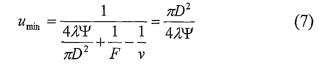

- The chart for umin with and without the EDOF element of the present invention is plotted in
Fig. 10 B. As could be seen, the minimal distance is much smaller when the invented element is in use. Thus, the overall range of focus is much larger. It should be noted that for the human eye, v=15mm. - Turning back to
Fig. 1C exemplifying an imaging arrangement of the present invention formed by a lenslet array and an EDOF elements' array (suitable to be used with a display panel or screen), the required parameters of the imaging arrangement can be estimated as follows: - Let us assume that u, which is the distance between the
screen 13 and thelenslet array 12A is about 2mm; v, which is the distance between thescreen 13 and the closest focus plane FP is 40cm; and R, which is the distance between theeye 16 and the closest focus plane FP, is about 1m. Theobject 13 is constituted by the display of the mobile phone or the screen. Basically, thelenslet array 12A images theobject plane 13 on the closest focus plane FP, i.e.:

which provides f=2.01mm. - The defocusing parameter is defined as:

where λ is the wavelength. - With the use of EDOF, this parameter can reach the value of 15 and without the EDOF element - the value of 2-3 without distorting the image quality. The diameter, D, of the lenses in the lenslet array can be found such that the minimal value for the distance between the
screen 13 and the closest focus plane FP, (Vmin), will be very close to theobject plane 13 to have minimal demagnification. The demagnification factor is:
- To have Vmin=u=2mm, one needs:

- This yields:

- It should be noted that without the EDOF element the minimal distance v would have been:

which means a demagnification factor of 8 (16mm/2mm). Such a demagnification would not have allowed seeing the characters in the display. - Attachment of the
lenslet array 12A to the screen decreased the visible resolution. The resolution of such an imaging system is limited by the factor of:
- Since the details appearing in the screen are larger than that, the resolution is not damaged by the imaging lenslet array.
- Following the computations presented above, a person with normal vision that will focus his eyes on the screen (or on a plane positioned 2mm behind it) will see the image in focus as well.
- The technique of the present invention could be barrier breaking in a vast set of applications including, but not limited to, the following: conventional office devices containing camera such as camcorders, scanners (e.g., barcode scanners) and web cams; conventional imaging systems including camera and detectors, i.e. cellular cameras, car cameras, surveillances cameras, machine vision, photography, HDTV, video conferences, radar imaging systems (that typically suffer from defocus problems), endoscopy and passive bio medical inspections, tomography, display panels, etc. The usage of the depth of focus extending element of the present invention in endoscopy and passive biomedical inspections allows for in-body imaging to see organs in focus that otherwise are not, since there is no control on the exact position of the medical apparatus. Some other possible applications of the present invention include correcting chromatic aberrations in various optical systems, for example in optical communication; media reader/writers used with information carriers such as conventional DVD, or multi-layer information carriers utilizing light reflection or fluorescence.
- The present invention may also be used in ophthalmic applications as a contact lens, a spectacle lens, an intraocular lens, or any other lens used around or inserted into any part of the eye. An obvious example is the use of the invention for the benefit of short sighted (myopic) people who develop presbyopia, the need for reading glasses as a result of age-related changes in their natural eye lens. In such an application, those people may use a single lens, as a spectacle lens, contact lens, intracorneal lens, phakic intraocular lens or aphakic intraocular lens, or a lens inserted elsewhere in the eye. In this fashion, they will use one lens for seeing at any distance, near or far. Another obvious utilization of the invention is in an intraocular lens, the artificial lens implanted in the eye after removal of a cataract. Currently, the regular artificial lens has only a single focus and thus the person into whose eye the lens was implanted has a very limited depth of focus and has to use spectacles for most distances of regard. Incorporation of the invention into the implanted lens will afford the patient focused vision at all distances. Another example of ophthalmic use is as a replacement of multifocal (progressive) spectacle lenses, which are conventionally designed such that every segment of the lens surface has a different focus and thus the patient has to move his eyes to focus on objects at different distances. Incorporation of the invention into a spectacle or contact lens will enable the presbyopic wearer to see objects in focus at all distances through any part of the lens.
- In all the applications of the invention, including the examples above, the image from objects at different distances are focused on the retina (or sensor) without appreciable loss of energy, in contradistinction to the situation in multifocal contact or intraocular lenses.
- Those skilled in the art will readily appreciate that various modifications and changes can be applied to the embodiments of the invention described hereinbefore without departing from its scope defined in and by the appended claims.
- The invention is further described by means of the following:
- 1. An imaging arrangement comprising: an imaging lens assembly including at least one lens having a certain affective aperture, and at least one optical element associated with said at least one lens and configured to provide an extended depth of focus of the imaging arrangement, said optical element being configured as a phase-affecting, non-diffractive optical element defining a spatially low frequency phase transition, said optical element together with its associated lens defining a predetermined pattern formed by spaced-apart optically transparent features of different optical properties, position of at least one phase transition region of the optical element within the lens plane being determined by at least a dimension of said affective aperture.
- 2. The arrangement of
point 1, wherein said lens assembly includes the single lens associated with the single optical element. - 3. The arrangement of
point 1, comprising the lens assembly including an array of lenses, and an array of the optical elements, each optical element being associated with the corresponding one of the lenses. - 4. The arrangement of any one of preceding points, wherein said optical element is configured as a phase-only element.
- 5. The arrangement of point -4, wherein said optical element is configured as a binary mask.
- 6. The arrangement of any one of
point 1 to 3, wherein said optical element is a configured as a phase and amplitude affecting element. - 7. The arrangement of any one of preceding point , wherein the optical element is configured to maximize a defocused optical transfer function (OTF) of the imaging arrangement by providing the out of focus OTF as much as possible away from zero.
- 8. The arrangement of
point 7, wherein the optical element is configured to produce proper phase interference relation between light portions passing through different regions of the imaging arrangement corresponding to the different features of the pattern to thereby reduce a quadratic phase factor resulting from light getting out of focus of the imaging lens. - 9. The arrangement of any one of preceding points, wherein said at least one transition region is configured as a pi-phase transition for a certain wavelength for which the optical element is designed.
- 10. The arrangement of any one ofpreceding points, wherein the position of said at least one transition region with respect to the imaging lens is determined by optical power of the imaging lens.
- 11. The arrangement of any one of
points 7 to 10, wherein the position for N transition regions of the optical element within the imaging lens plane maximizing the OTF is determined as:
values for an providing maximum for minima of an expression for auto correlation of a Coherent Transfer Function (CTF) of the imaging lens, where an equals either 1 or -1, D̃(v) being the CTF of the imaging lens corresponding to out of focus position of an object being imaged and being determined as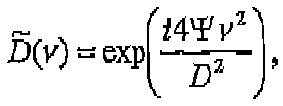
- 12. The arrangement of any one of preceding points, wherein said at least one transition region has a sub-pattern formed by an array of variable phase transition sub-regions.
- 13. The arrangement of any one of points 9 to 11, wherein said at least one pi-phase transition region has a sub-pattern formed by an array of variable pi-phase transition sub-regions.
- 14. The arrangement of any one of preceding points, wherein the optical element is configured as at least one annular transition region.
- 15. The arrangement of any one of
points 1 to 14, wherein the optical element is configured as a grid. - 16. The arrangement of any one of preceding points, wherein said optical element is spaced-apart from the imaging lens along an optical axis of the imaging lens.
- 17. The arrangement of any one of
points 1 to 15, wherein said optical element is attached to the imaging lens. - 18. The arrangement of any one of
points 1 to 15, wherein said optical element is made integral with the imaging lens. - 19. The arrangement of any one of preceding points; wherein said optical element is configured as a mask formed by an array of said transition regions arranged in a spaced-apart relationship being spaced by the optically transparent regions of the imaging lens within the imaging lens plane.
- 20. The arrangement of points18, wherein said at least one transition region is formed as a surface relief on the imaging lens surface, defining a lens thickness within said at least one region different from that within other regions of the lens.
- 21. The arrangement of points18 or 20, wherein said at least one transition region is formed by a material having refractive index different from that of the imaging lens material
- 22. The arrangement of points 18 or 21, wherein said optical element is configured as a mask formed by an array of the phase transition regions formed by a material having refractive index different from that of the imaging lens material.
- 23. The arrangement of any one of
points 7 to 22, wherein the optical element is configured to maximize the OTF by reducing high-frequency cancellation at large shifts of a Coherent Transfer Function (CTF) of the imaging lens. - 24. The arrangement of any one of
points 7 to 23, wherein the optical element is configured to maximize the OTF by reducing sensitivity of the lens arrangement to shifts of a Coherent Transfer Function (CTF) of the imaging lens while getting out of focus. - 25. The arrangement of point 24, wherein the optical element is configured to produce periodic replication of a lateral phase shape of a light field propagating through the imaging lens.
- 26. The arrangement of point 24, wherein the optical element is configured in accordance with a free space propagation of the optical element function for a distance between the optical element and the imaging lens plane.
- 27. The arrangement of any one of preceding points, for use in patients' spectacles.
- 28. On optical element for use with an imaging lens in the imaging arrangement of any one of preceding points for extending depth of focus of imaging, the optical element being configured as a phase-affecting, non-diffractive optical element defining a predetermined pattern of spatially low frequency phase transitions, said pattern being defined by an affective aperture of the given imaging lens.
- 29. A system for creating an image of an object on a detector plane, the system comprising the imaging lens arrangement of any one of points1 to 26,
- 30. The system of point 28, wherein said object is a screen of a display device to be imaged on the eye retina constituting the detector plane.
- 31. A display device carrying the imaging arrangement of any one of preceding
- 32. A method for providing a certain extended depth of focus of an imaging system, the method comprising applying an aperture coding to an imaging lens having a certain effective aperture, by applying to the imaging lens a phase-affecting non-diffractive optical element configured to define a spatially low frequency phase transition arrangement and thereby provide a predetermined pattern of spaced-apart substantially optically transparent features of different optical properties within the imaging lens plane, thereby producing phase interference relation between light portions passing through different regions of the lens arrangement corresponding to the different features of the pattern so as to reduce a quadratic phase factor resulting from light getting out of focus of the imaging lens and maximize a defocused optical transfer function (OTF) of the imaging lens arrangement.
- 33. A method for designing the optical element of point 27, said designing comprising selecting N positions for the phase transitions within the imaging lens effective aperture as those providing maximal contrast of an Optical Transfer Function (OTF) of the imaging system under a set of out of focus locations, thereby providing the out of focus OTF as much as possible away from zero.
- 34. The method of point 33; wherein the- position for said N transition: regions of the optical element within the imaging lens plane maximizing the OTF are determined as:

values for an providing maximum for minima of an expression for auto correlation of a Coherent Transfer Function (CTF) of the imaging lens, where an equals either 1 or -1, D̃(v) being the CTF of the imaging lens corresponding to out of focus position of an object being imaged and being determined as
- 35. The method of points33or34, comprising fabricating a mask formed by an arrangement of the N transitions spaced-apart from each other in accordance with said selected N positions.
- 36. The method of point 35, comprising attaching said mask to the surface of the imaging lens aperture.
- 37. The method of points 33, comprising patterning the surface of the imaging lens aperture to form a mask of the N transitions spaced-apart from each other in accordance with said selected N positions.
- 38. The method of points 36 or 37, comprising providing said surface substantially flat to thereby allow insertion of the patterned imaging lens into a patient's eye.
- 39. The method of any one of points 33 to 38, wherein the designing of the optical element comprises producing a phase interference relation between light portions passing through said N regions and spaces between them to thereby "reduce a quadratic phase factor resulting from light getting out of focus of the imaging lens and maximize a defocused optical transfer function (OTF) of an arrangement formed by the imaging lens and the optical element.
- 40. The method of point 37, wherein said patterning comprises applying material removal to the lens regions within said N positions, and filling said regions, from which the lens material has been removed, by a material of a refraction index different from that of the lens, so as to, provide a refraction index difference such that the outer region of the patterned lens is flat and proper equalization between the different material regions is provided to produce a phase interference relation between light portions passing through different material regions to thereby reduce a quadratic phase factor resulting from light getting out of focus of the imaging lens and maximize a defocused optical transfer function (OTF) of the patterned imaging lens.
- 41. The method of point 37, wherein said patterning comprises applying diffusion or photo polymerization to the lens regions within said N positions, so as to provide a refraction index difference between said N regions and spaces between them such that the outer region of the patterned lens is flat and proper equalization between the different material regions is provided to produce a phase interference relation between light portions passing through different material regions to thereby reduce a quadratic phase factor resulting from light getting out of focus of the imaging lens and maximize a defocused optical transfer function (OTF) of the patterned imaging lens.
- 42. The method of point 33, comprising implanting in the patient's eye tissue, within said selected N positions, an artificial tissue having a refraction index different from that of the eye tissue.
Claims (15)
- An imaging lens having an optical power and comprising an outer surface defining a certain affective aperture, the imaging lens comprising a phase affecting pattern, and being characterized in that:said phase affecting pattern is formed by regions of different refractive indices along said surface, materials and features of the pattern being selected to provide a refraction index difference between said regions such that said outer surface of the lens is flat while with a phase difference between said regions corresponding to a desired phase interference relation between light portions passing through the different regions of the pattern, extending a depth of focus of said lens to 5 diopters around said optical power of the lens.
- The imaging lens of Claim 1, wherein said pattern is a phase-only affecting pattern.
- The imaging lens of Claims 1 or 2, wherein said pattern is configured as a binary phase affecting pattern.
- The imaging lens of any one of Claims 1 to 3, wherein the phase difference between the regions corresponds to a pi-phase transition for a certain wavelength for which the imaging lens is designed.
- The imaging lens of any one of Claims 1 to 4, wherein positions for N regions of the same refractive index spaced a distance Δv between them within said surface are selected for maximizing OTF of the lens being determined as:

values for an providing maximum for minima of an expression for auto correlation of a Coherent Transfer Function (CTF) of the imaging lens, where an equals either 1 or -1, D(v) being the CTF of the imaging lens corresponding to out of focus position of an object being imaged and being determined as
- The imaging lens of any one of Claims 1 to 5, wherein the pattern comprises at least one annular phase transition region of the refractive index different from its surroundings.
- The imaging lens of any one of Claims 1 to 5, wherein said pattern is configured as a grid.
- The imaging lens of any one of Claims 1 to 7, wherein said pattern is made by etching said surface in predetermined spaced-apart region forming a surface relief and filling the etched regions with a material having the refractive index different from that of the lens thereby creating said flat surface.
- The imaging lens of any one of Claims 1 to 8, wherein said pattern is configured to maximize OTF of the lens by reducing high-frequency cancellation at large shifts of a Coherent Transfer Function (CTF) of the lens.
- The imaging lens of any one of Claims 1 to 9, wherein the optical element is configured to maximize OTF of the lens by reducing sensitivity of the lens to shifts of a Coherent Transfer Function (CTF) of the lens while getting out of focus.
- The imaging lens of any one of Claims 1 to 10, wherein said pattern is configured to produce periodic replication of a lateral phase shape of a light field propagating through the lens.
- The imaging lens of any one of Claims 1 to 11, for ophthalmic applications, said imaging lens being an eye lens such as a contact lens or intraocular lens.
- The imaging lens of Claim 12, wherein a dimension of the effective aperture is in a range of 2-7 mm.
- The imaging lens of any one of Claims 1 to 13, wherein the depth of focus is in between -1.5 to 3.5 diopters.
- The imaging lens of any one of Claims 1 to 13, wherein the depth of focus is in between -2.5 to 2.5 diopters.
Applications Claiming Priority (3)
| Application Number | Priority Date | Filing Date | Title |
|---|---|---|---|
| US60163804P | 2004-08-16 | 2004-08-16 | |
| US10/974,943 US7061693B2 (en) | 2004-08-16 | 2004-10-28 | Optical method and system for extended depth of focus |
| EP05770097.3A EP1779152B1 (en) | 2004-08-16 | 2005-08-11 | Method and system for extending the depth of focus |
Related Parent Applications (2)
| Application Number | Title | Priority Date | Filing Date |
|---|---|---|---|
| EP05770097.3A Division-Into EP1779152B1 (en) | 2004-08-16 | 2005-08-11 | Method and system for extending the depth of focus |
| EP05770097.3 Division | 2005-08-11 |
Publications (1)
| Publication Number | Publication Date |
|---|---|
| EP2302421A1 true EP2302421A1 (en) | 2011-03-30 |
Family
ID=35159655
Family Applications (3)
| Application Number | Title | Priority Date | Filing Date |
|---|---|---|---|
| EP05770097.3A Active EP1779152B1 (en) | 2004-08-16 | 2005-08-11 | Method and system for extending the depth of focus |
| EP10183895A Withdrawn EP2302421A1 (en) | 2004-08-16 | 2005-08-11 | System for extending the depth of focus |
| EP17202513.2A Pending EP3364220A1 (en) | 2004-08-16 | 2005-08-11 | Method and system for extending the depth of focus |
Family Applications Before (1)
| Application Number | Title | Priority Date | Filing Date |
|---|---|---|---|
| EP05770097.3A Active EP1779152B1 (en) | 2004-08-16 | 2005-08-11 | Method and system for extending the depth of focus |
Family Applications After (1)
| Application Number | Title | Priority Date | Filing Date |
|---|---|---|---|
| EP17202513.2A Pending EP3364220A1 (en) | 2004-08-16 | 2005-08-11 | Method and system for extending the depth of focus |
Country Status (9)
| Country | Link |
|---|---|
| US (1) | US7061693B2 (en) |
| EP (3) | EP1779152B1 (en) |
| JP (1) | JP5036540B2 (en) |
| KR (1) | KR101165051B1 (en) |
| CN (1) | CN101014884B (en) |
| ES (1) | ES2660408T3 (en) |
| HU (1) | HUE036169T2 (en) |
| RU (1) | RU2436135C2 (en) |
| WO (1) | WO2006018834A1 (en) |
Cited By (3)
| Publication number | Priority date | Publication date | Assignee | Title |
|---|---|---|---|---|
| WO2013114075A1 (en) * | 2012-02-03 | 2013-08-08 | University Of Southampton | Super-oscillatory lens device |
| WO2014086539A1 (en) * | 2012-12-07 | 2014-06-12 | Thales | Optical system comprising an optical phase and/or amplitude mask filter having a periodic structure |
| WO2014135986A3 (en) * | 2013-03-07 | 2015-01-08 | Amo Groningen B.V. | Lens providing extended depth of focus and method relating to same |
Families Citing this family (181)
| Publication number | Priority date | Publication date | Assignee | Title |
|---|---|---|---|---|
| JP4377404B2 (en) * | 2003-01-16 | 2009-12-02 | ディ−ブルアー テクノロジス リミテッド | Camera with image enhancement function |
| US8294999B2 (en) | 2003-01-16 | 2012-10-23 | DigitalOptics Corporation International | Optics for an extended depth of field |
| US7773316B2 (en) * | 2003-01-16 | 2010-08-10 | Tessera International, Inc. | Optics for an extended depth of field |
| US7628810B2 (en) | 2003-05-28 | 2009-12-08 | Acufocus, Inc. | Mask configured to maintain nutrient transport without producing visible diffraction patterns |
| US7944467B2 (en) * | 2003-12-01 | 2011-05-17 | Omnivision Technologies, Inc. | Task-based imaging systems |
| CN101373272B (en) * | 2003-12-01 | 2010-09-01 | 全视Cdm光学有限公司 | System and method for optimizing optical and digital system designs |
| US7365917B2 (en) * | 2004-08-16 | 2008-04-29 | Xceed Imaging Ltd. | Optical method and system for extended depth of focus |
| EP2328006B1 (en) * | 2005-09-19 | 2014-08-06 | OmniVision CDM Optics, Inc. | Task-based imaging systems |
| US20070239417A1 (en) * | 2006-03-31 | 2007-10-11 | D-Blur Technologies Ltd. | Camera performance simulation |
| ATE553406T1 (en) * | 2006-04-20 | 2012-04-15 | Xceed Imaging Ltd | SYSTEM AND METHOD FOR EXTENDED DEPTH OF FOCUS AND NON-COHERENT LIGHT IMAGING |
| WO2007122615A2 (en) * | 2006-04-20 | 2007-11-01 | Xceed Imaging Ltd. | All optical system and method for providing extended depth of focus of imaging |
| EP2035879A4 (en) * | 2006-06-06 | 2010-03-17 | Xceed Imaging Ltd | Optical system and method for multi-range and dual-range imaging |
| WO2008087485A2 (en) * | 2006-09-14 | 2008-07-24 | Tessera Technologies Hungary Kft. | Imaging system with relaxed assembly tolerances and associated methods |
| WO2008087486A2 (en) * | 2006-09-14 | 2008-07-24 | Tessera Technologies Hungary Kft. | Imaging system with improved image quality and associated methods |
| US7646549B2 (en) * | 2006-12-18 | 2010-01-12 | Xceed Imaging Ltd | Imaging system and method for providing extended depth of focus, range extraction and super resolved imaging |
| EP1952752B2 (en) * | 2007-01-31 | 2019-10-16 | Richard Wolf GmbH | Endoscope system |
| EP1978394A1 (en) * | 2007-04-06 | 2008-10-08 | Global Bionic Optics Pty Ltd. | Optical system for increasing depth of field |
| EP2187841A4 (en) * | 2007-08-02 | 2016-09-21 | Ocular Optics Inc | Multi-focal intraocular lens system and methods |
| US8747466B2 (en) | 2007-08-27 | 2014-06-10 | Amo Groningen, B.V. | Intraocular lens having extended depth of focus |
| US8974526B2 (en) | 2007-08-27 | 2015-03-10 | Amo Groningen B.V. | Multizonal lens with extended depth of focus |
| US8740978B2 (en) * | 2007-08-27 | 2014-06-03 | Amo Regional Holdings | Intraocular lens having extended depth of focus |
| US20090062911A1 (en) * | 2007-08-27 | 2009-03-05 | Amo Groningen Bv | Multizonal lens with extended depth of focus |
| US9216080B2 (en) * | 2007-08-27 | 2015-12-22 | Amo Groningen B.V. | Toric lens with decreased sensitivity to cylinder power and rotation and method of using the same |
| ATE523810T1 (en) | 2008-02-15 | 2011-09-15 | Amo Regional Holdings | SYSTEM, GLASS LENS AND METHOD FOR EXPANDING THE DEPTH OF FOCUS |
| US8439498B2 (en) | 2008-02-21 | 2013-05-14 | Abbott Medical Optics Inc. | Toric intraocular lens with modified power characteristics |
| EP2891918A1 (en) * | 2008-02-29 | 2015-07-08 | Global Bionic Optics Pty Ltd. | Single-lens extended depth-of-field imaging systems |
| DE102008018636B4 (en) * | 2008-04-11 | 2011-01-05 | Storz Endoskop Produktions Gmbh | Device and method for endoscopic 3D data acquisition |
| US7871162B2 (en) * | 2008-04-24 | 2011-01-18 | Amo Groningen B.V. | Diffractive multifocal lens having radially varying light distribution |
| US8231219B2 (en) * | 2008-04-24 | 2012-07-31 | Amo Groningen B.V. | Diffractive lens exhibiting enhanced optical performance |
| KR101422503B1 (en) * | 2008-05-09 | 2014-07-25 | 삼성전자주식회사 | Lens with extended depth of focus and optical system having the same |
| US8862447B2 (en) | 2010-04-30 | 2014-10-14 | Amo Groningen B.V. | Apparatus, system and method for predictive modeling to design, evaluate and optimize ophthalmic lenses |
| US8866920B2 (en) | 2008-05-20 | 2014-10-21 | Pelican Imaging Corporation | Capturing and processing of images using monolithic camera array with heterogeneous imagers |
| US11792538B2 (en) | 2008-05-20 | 2023-10-17 | Adeia Imaging Llc | Capturing and processing of images including occlusions focused on an image sensor by a lens stack array |
| US8902321B2 (en) | 2008-05-20 | 2014-12-02 | Pelican Imaging Corporation | Capturing and processing of images using monolithic camera array with heterogeneous imagers |
| MX2011006600A (en) * | 2008-12-19 | 2011-06-30 | Novartis Ag | Correction of peripheral defocus of an eye and control of refractive error development. |
| US8646916B2 (en) | 2009-03-04 | 2014-02-11 | Perfect Ip, Llc | System for characterizing a cornea and obtaining an opthalmic lens |
| MX2011009196A (en) | 2009-03-04 | 2011-11-18 | Aaren Scientific Inc | System for forming and modifying lenses and lenses formed thereby. |
| US8292952B2 (en) | 2009-03-04 | 2012-10-23 | Aaren Scientific Inc. | System for forming and modifying lenses and lenses formed thereby |
| EP2228677A1 (en) * | 2009-03-09 | 2010-09-15 | Global Bionic Optics Pty Ltd. | Extended depth-of-field surveillance imaging system |
| CA2770735C (en) | 2009-08-13 | 2017-07-18 | Acufocus, Inc. | Masked intraocular implants and lenses |
| US10004593B2 (en) | 2009-08-13 | 2018-06-26 | Acufocus, Inc. | Intraocular lens with elastic mask |
| CN101995646B (en) * | 2009-08-17 | 2013-03-27 | 大立光电股份有限公司 | Image-taking lens system |
| WO2011035033A1 (en) | 2009-09-16 | 2011-03-24 | Indiana University Research & Technology Corporation | Simultaneous vision lenses, design strategies, apparatuses, methods, and systems |
| US20120281280A1 (en) | 2009-10-15 | 2012-11-08 | Sony Corporation | Birefringent device with application specific pupil function and optical device |
| EP2502115A4 (en) | 2009-11-20 | 2013-11-06 | Pelican Imaging Corp | Capturing and processing of images using monolithic camera array with heterogeneous imagers |
| US8325420B2 (en) * | 2009-11-24 | 2012-12-04 | Massachusetts Institute Of Technology | Annular solid immersion lenses and methods of making them |
| US8339481B2 (en) * | 2009-12-14 | 2012-12-25 | Samsung Electronics Co., Ltd. | Image restoration devices adapted to remove artifacts from a restored image and associated image restoration methods |
| EP3824846A1 (en) | 2009-12-18 | 2021-05-26 | AMO Groningen B.V. | Limited echelette lens |
| US8531783B2 (en) | 2010-02-09 | 2013-09-10 | Xceed Imaging Ltd. | Imaging method and system for imaging with extended depth of focus |
| US8416334B2 (en) | 2010-04-27 | 2013-04-09 | Fm-Assets Pty Ltd. | Thick single-lens extended depth-of-field imaging systems |
| KR101756910B1 (en) | 2010-05-11 | 2017-07-26 | 삼성전자주식회사 | Apparatus and method for processing light field data using mask with attenuation pattern |
| KR101824672B1 (en) | 2010-05-12 | 2018-02-05 | 포토네이션 케이맨 리미티드 | Architectures for imager arrays and array cameras |
| EP2616023A2 (en) | 2010-09-13 | 2013-07-24 | The Regents of the University of Colorado, a body corporate | Extended depth of field optics with variable pupil diameter |
| KR101849432B1 (en) * | 2010-12-01 | 2018-04-16 | 아드렌스 비콘 인코포레이티드 | Variable power endoscope based on liquid lens technology |
| EP3330776A1 (en) | 2010-12-01 | 2018-06-06 | AMO Groningen B.V. | A multifocal lens having an optical add power progression, and a system and method of providing same |
| US8878950B2 (en) | 2010-12-14 | 2014-11-04 | Pelican Imaging Corporation | Systems and methods for synthesizing high resolution images using super-resolution processes |
| US9931200B2 (en) | 2010-12-17 | 2018-04-03 | Amo Groningen B.V. | Ophthalmic devices, systems, and methods for optimizing peripheral vision |
| US8894204B2 (en) | 2010-12-17 | 2014-11-25 | Abbott Medical Optics Inc. | Ophthalmic lens, systems and methods having at least one rotationally asymmetric diffractive structure |
| US10394051B2 (en) * | 2010-12-23 | 2019-08-27 | Brien Holden Vision Institute | Toric ophthalmic lens having extended depth of focus |
| WO2012120470A1 (en) * | 2011-03-10 | 2012-09-13 | Optika Amuka (A.A.) Ltd. | Stereographic viewing with extended depth of field |
| WO2012138426A2 (en) * | 2011-04-04 | 2012-10-11 | Elenza, Inc. | An implantable ophthalmic device with multiple static apertures |
| US9579191B2 (en) | 2011-04-07 | 2017-02-28 | Novartis Ag | Optical structures with nanostructre features and methods of use and manufacture |
| JP2014519741A (en) | 2011-05-11 | 2014-08-14 | ペリカン イメージング コーポレイション | System and method for transmitting and receiving array camera image data |
| US20130265459A1 (en) | 2011-06-28 | 2013-10-10 | Pelican Imaging Corporation | Optical arrangements for use with an array camera |
| WO2013043761A1 (en) | 2011-09-19 | 2013-03-28 | Pelican Imaging Corporation | Determining depth from multiple views of a scene that include aliasing using hypothesized fusion |
| EP2761534B1 (en) | 2011-09-28 | 2020-11-18 | FotoNation Limited | Systems for encoding light field image files |
| US8937646B1 (en) | 2011-10-05 | 2015-01-20 | Amazon Technologies, Inc. | Stereo imaging using disparate imaging devices |
| CA2857306C (en) | 2011-12-02 | 2017-07-25 | Acufocus, Inc. | Ocular mask having selective spectral transmission |
| US9066784B2 (en) * | 2011-12-19 | 2015-06-30 | Alcon Lensx, Inc. | Intra-surgical optical coherence tomographic imaging of cataract procedures |
| TWI594723B (en) * | 2011-12-19 | 2017-08-11 | 愛爾康眼科手術激光股份有限公司 | Image processor for intra-surgical optical coherence tomographic imaging of laser cataract procedures |
| US10656437B2 (en) | 2011-12-21 | 2020-05-19 | Brien Holden Vision Institute Limited | Optical lens with halo reduction |
| US8556417B2 (en) * | 2012-02-02 | 2013-10-15 | Novartis Ag | Apodized hybrid diffractive-refractive IOL for pseudo-accommodation |
| US9412206B2 (en) | 2012-02-21 | 2016-08-09 | Pelican Imaging Corporation | Systems and methods for the manipulation of captured light field image data |
| JP5417554B1 (en) * | 2012-03-30 | 2014-02-19 | 三菱レイヨン株式会社 | Rod lens array and image sensor head using the same |
| TWI588560B (en) | 2012-04-05 | 2017-06-21 | 布萊恩荷登視覺協會 | Lenses, devices, methods and systems for refractive error |
| US9210392B2 (en) | 2012-05-01 | 2015-12-08 | Pelican Imaging Coporation | Camera modules patterned with pi filter groups |
| WO2014005123A1 (en) | 2012-06-28 | 2014-01-03 | Pelican Imaging Corporation | Systems and methods for detecting defective camera arrays, optic arrays, and sensors |
| US20140002674A1 (en) | 2012-06-30 | 2014-01-02 | Pelican Imaging Corporation | Systems and Methods for Manufacturing Camera Modules Using Active Alignment of Lens Stack Arrays and Sensors |
| CN107346061B (en) | 2012-08-21 | 2020-04-24 | 快图有限公司 | System and method for parallax detection and correction in images captured using an array camera |
| WO2014032020A2 (en) | 2012-08-23 | 2014-02-27 | Pelican Imaging Corporation | Feature based high resolution motion estimation from low resolution images captured using an array source |
| BR112015004617A2 (en) | 2012-08-31 | 2017-07-04 | Amo Groningen Bv | systems and methods for extended multi-lens lens extended focus depth |
| US9214013B2 (en) | 2012-09-14 | 2015-12-15 | Pelican Imaging Corporation | Systems and methods for correcting user identified artifacts in light field images |
| CN104685860A (en) | 2012-09-28 | 2015-06-03 | 派力肯影像公司 | Generating images from light fields utilizing virtual viewpoints |
| US11126040B2 (en) | 2012-09-30 | 2021-09-21 | Optica Amuka (A.A.) Ltd. | Electrically-tunable lenses and lens systems |
| US10036901B2 (en) | 2012-09-30 | 2018-07-31 | Optica Amuka (A.A.) Ltd. | Lenses with electrically-tunable power and alignment |
| US9201250B2 (en) | 2012-10-17 | 2015-12-01 | Brien Holden Vision Institute | Lenses, devices, methods and systems for refractive error |
| CN104768499B (en) | 2012-10-17 | 2017-06-23 | 华柏恩视觉研究中心 | For ametropic eyeglass, device, method and system |
| US9143711B2 (en) | 2012-11-13 | 2015-09-22 | Pelican Imaging Corporation | Systems and methods for array camera focal plane control |
| CA2877203A1 (en) | 2012-12-04 | 2014-06-12 | Amo Groningen B.V. | Lenses, systems and methods for providing binocular customized treatments to correct presbyopia |
| US9462164B2 (en) | 2013-02-21 | 2016-10-04 | Pelican Imaging Corporation | Systems and methods for generating compressed light field representation data using captured light fields, array geometry, and parallax information |
| US9253380B2 (en) | 2013-02-24 | 2016-02-02 | Pelican Imaging Corporation | Thin form factor computational array cameras and modular array cameras |
| US9774789B2 (en) | 2013-03-08 | 2017-09-26 | Fotonation Cayman Limited | Systems and methods for high dynamic range imaging using array cameras |
| US8866912B2 (en) | 2013-03-10 | 2014-10-21 | Pelican Imaging Corporation | System and methods for calibration of an array camera using a single captured image |
| US9521416B1 (en) | 2013-03-11 | 2016-12-13 | Kip Peli P1 Lp | Systems and methods for image data compression |
| CA2875873C (en) | 2013-03-11 | 2022-06-21 | Abbott Medical Optics Inc. | Intraocular lens that matches an image surface to a retinal shape, and method of designing same |
| US9888194B2 (en) | 2013-03-13 | 2018-02-06 | Fotonation Cayman Limited | Array camera architecture implementing quantum film image sensors |
| US9106784B2 (en) | 2013-03-13 | 2015-08-11 | Pelican Imaging Corporation | Systems and methods for controlling aliasing in images captured by an array camera for use in super-resolution processing |
| WO2014165244A1 (en) | 2013-03-13 | 2014-10-09 | Pelican Imaging Corporation | Systems and methods for synthesizing images from image data captured by an array camera using restricted depth of field depth maps in which depth estimation precision varies |
| WO2014164550A2 (en) | 2013-03-13 | 2014-10-09 | Pelican Imaging Corporation | System and methods for calibration of an array camera |
| WO2014153098A1 (en) | 2013-03-14 | 2014-09-25 | Pelican Imaging Corporation | Photmetric normalization in array cameras |
| US9578259B2 (en) | 2013-03-14 | 2017-02-21 | Fotonation Cayman Limited | Systems and methods for reducing motion blur in images or video in ultra low light with array cameras |
| US9427922B2 (en) | 2013-03-14 | 2016-08-30 | Acufocus, Inc. | Process for manufacturing an intraocular lens with an embedded mask |
| US10122993B2 (en) | 2013-03-15 | 2018-11-06 | Fotonation Limited | Autofocus system for a conventional camera that uses depth information from an array camera |
| US9497429B2 (en) | 2013-03-15 | 2016-11-15 | Pelican Imaging Corporation | Extended color processing on pelican array cameras |
| US9497370B2 (en) | 2013-03-15 | 2016-11-15 | Pelican Imaging Corporation | Array camera architecture implementing quantum dot color filters |
| US9445003B1 (en) | 2013-03-15 | 2016-09-13 | Pelican Imaging Corporation | Systems and methods for synthesizing high resolution images using image deconvolution based on motion and depth information |
| WO2014145856A1 (en) | 2013-03-15 | 2014-09-18 | Pelican Imaging Corporation | Systems and methods for stereo imaging with camera arrays |
| US9633442B2 (en) | 2013-03-15 | 2017-04-25 | Fotonation Cayman Limited | Array cameras including an array camera module augmented with a separate camera |
| WO2015003739A1 (en) * | 2013-07-08 | 2015-01-15 | Wavelight Gmbh | Technique for treating presbyopia |
| WO2015048694A2 (en) | 2013-09-27 | 2015-04-02 | Pelican Imaging Corporation | Systems and methods for depth-assisted perspective distortion correction |
| WO2015070105A1 (en) | 2013-11-07 | 2015-05-14 | Pelican Imaging Corporation | Methods of manufacturing array camera modules incorporating independently aligned lens stacks |
| US10119808B2 (en) | 2013-11-18 | 2018-11-06 | Fotonation Limited | Systems and methods for estimating depth from projected texture using camera arrays |
| EP3075140B1 (en) | 2013-11-26 | 2018-06-13 | FotoNation Cayman Limited | Array camera configurations incorporating multiple constituent array cameras |
| ES2865137T3 (en) * | 2013-12-23 | 2021-10-15 | Alcon Inc | Wide field of view surgical OCT display system |
| US10089740B2 (en) | 2014-03-07 | 2018-10-02 | Fotonation Limited | System and methods for depth regularization and semiautomatic interactive matting using RGB-D images |
| EP3116442A1 (en) | 2014-03-10 | 2017-01-18 | Amo Groningen B.V. | Intraocular lens that improves overall vision where there is a local loss of retinal function |
| CA2946356C (en) | 2014-04-21 | 2022-09-20 | Amo Groningen B.V. | Ophthalmic devices, system and methods that improve peripheral vision |
| AU2015270158B2 (en) | 2014-06-05 | 2017-11-09 | Optica Amuka (A.A.) Ltd. | Control of dynamic lenses |
| US9521319B2 (en) | 2014-06-18 | 2016-12-13 | Pelican Imaging Corporation | Array cameras and array camera modules including spectral filters disposed outside of a constituent image sensor |
| RU2595759C2 (en) * | 2014-07-04 | 2016-08-27 | Самсунг Электроникс Ко., Лтд. | Method and image capturing device and simultaneous extraction of depth |
| US9872012B2 (en) | 2014-07-04 | 2018-01-16 | Samsung Electronics Co., Ltd. | Method and apparatus for image capturing and simultaneous depth extraction |
| EP3191022B1 (en) | 2014-09-09 | 2022-05-04 | Staar Surgical Company | Ophthalmic implants with extended depth of field and enhanced distance visual acuity |
| ES2529267B1 (en) * | 2014-09-25 | 2015-12-18 | Sergio Oscar Luque | Multifocal intraocular lens with extended depth of field |
| CN113256730B (en) | 2014-09-29 | 2023-09-05 | 快图有限公司 | System and method for dynamic calibration of an array camera |
| EP3220859B8 (en) | 2014-11-19 | 2020-06-10 | AcuFocus, Inc. | Fracturable mask for treating presbyopia |
| US9942474B2 (en) | 2015-04-17 | 2018-04-10 | Fotonation Cayman Limited | Systems and methods for performing high speed video capture and depth estimation using array cameras |
| EP3359987B1 (en) | 2015-10-05 | 2024-02-28 | AcuFocus, Inc. | Methods of molding intraocular lenses |
| WO2017083315A1 (en) * | 2015-11-09 | 2017-05-18 | Hoya Corporation | Optical devices having partial or incomplete optic and associated methods |
| CA3005891C (en) | 2015-11-24 | 2023-12-12 | Acufocus, Inc. | Toric small aperture intraocular lens with extended depth of focus |
| AU2017218681B2 (en) | 2016-02-09 | 2021-09-23 | Amo Groningen B.V. | Progressive power intraocular lens, and methods of use and manufacture |
| US11083566B2 (en) | 2016-02-29 | 2021-08-10 | Alcon Inc. | Ophthalmic lens having an extended depth of focus |
| US9968440B2 (en) | 2016-02-29 | 2018-05-15 | Novartis Ag | Ophthalmic lens having an extended depth of focus |
| JP6953423B2 (en) | 2016-03-09 | 2021-10-27 | スター サージカル カンパニー | Ophthalmic implants with extended depth of field and improved distant vision |
| EP3426191A1 (en) | 2016-03-11 | 2019-01-16 | Amo Groningen B.V. | Intraocular lenses that improve peripheral vision |
| AU2017237095B2 (en) | 2016-03-23 | 2022-08-04 | Johnson & Johnson Surgical Vision, Inc. | Ophthalmic apparatus with corrective meridians having extended tolerance band |
| US10649234B2 (en) | 2016-03-23 | 2020-05-12 | Johnson & Johnson Surgical Vision, Inc. | Ophthalmic apparatus with corrective meridians having extended tolerance band |
| EP3958048A1 (en) | 2016-04-17 | 2022-02-23 | Optica Amuka (A.A.) Ltd. | Liquid crystal lens with enhanced electrical drive |
| US11096778B2 (en) | 2016-04-19 | 2021-08-24 | Amo Groningen B.V. | Ophthalmic devices, system and methods that improve peripheral vision |
| WO2017216716A1 (en) | 2016-06-16 | 2017-12-21 | Optica Amuka (A.A.) Ltd. | Tunable lenses for spectacles |
| WO2018078439A2 (en) | 2016-10-25 | 2018-05-03 | Amo Groningen B.V. | Realistic eye models to design and evaluate intraocular lenses for a large field of view |
| US11675070B2 (en) * | 2016-12-23 | 2023-06-13 | Iee International Electronics & Engineering S.A. | High-resolution 3D radar wave imaging device |
| CA3056707A1 (en) | 2017-03-17 | 2018-09-20 | Amo Groningen B.V. | Diffractive intraocular lenses for extended range of vision |
| US10739227B2 (en) | 2017-03-23 | 2020-08-11 | Johnson & Johnson Surgical Vision, Inc. | Methods and systems for measuring image quality |
| CA3064764A1 (en) | 2017-05-24 | 2018-11-29 | The Trustees Of Columbia University In The City Of New York | Broadband achromatic flat optical components by dispersion-engineered dielectric metasurfaces |
| US11523897B2 (en) | 2017-06-23 | 2022-12-13 | Amo Groningen B.V. | Intraocular lenses for presbyopia treatment |
| WO2019002384A1 (en) | 2017-06-28 | 2019-01-03 | Amo Groningen B.V. | Diffractive lenses and related intraocular lenses for presbyopia treatment |
| CA3068351A1 (en) | 2017-06-28 | 2019-01-03 | Amo Groningen B.V. | Extended range and related intraocular lenses for presbyopia treatment |
| US11327210B2 (en) | 2017-06-30 | 2022-05-10 | Amo Groningen B.V. | Non-repeating echelettes and related intraocular lenses for presbyopia treatment |
| US11953764B2 (en) | 2017-07-10 | 2024-04-09 | Optica Amuka (A.A.) Ltd. | Tunable lenses with enhanced performance features |
| WO2019012385A1 (en) | 2017-07-10 | 2019-01-17 | Optica Amuka (A.A.) Ltd. | Virtual reality and augmented reality systems with dynamic vision correction |
| US10482618B2 (en) | 2017-08-21 | 2019-11-19 | Fotonation Limited | Systems and methods for hybrid depth regularization |
| KR20200047612A (en) | 2017-08-31 | 2020-05-07 | 메탈렌츠 인코포레이티드 | Transmissive metasurface lens integration |
| WO2019077442A1 (en) | 2017-10-16 | 2019-04-25 | Optica Amuka (A.A.) Ltd. | Spectacles with electrically-tunable lenses controllable by an external system |
| CN107589543B (en) * | 2017-10-18 | 2020-01-31 | 重庆大学 | Long-focus deep focusing lens based on normalized spectrum compression and design method |
| CA3082053A1 (en) | 2017-11-30 | 2019-06-06 | Amo Groningen B.V. | Intraocular lenses that improve post-surgical spectacle independent and methods of manufacturing thereof |
| US11301655B2 (en) | 2017-12-15 | 2022-04-12 | Cognex Corporation | Vision imaging system having a camera and dual aimer assemblies |
| US10832023B2 (en) | 2017-12-15 | 2020-11-10 | Cognex Corporation | Dual-imaging vision system camera and method for using the same |
| CN108325047B (en) * | 2018-03-26 | 2020-09-08 | 青岛市中心医院 | External guide cardiac catheter device |
| WO2019217471A1 (en) | 2018-05-09 | 2019-11-14 | Acufocus, Inc. | Intraocular implant with removable optic |
| EP3739375A4 (en) | 2018-07-03 | 2021-10-20 | National University Corporation Tokyo University of Agriculture and Technology | Stereoscopic glasses, method for designing spectacle lens used in same, and method for observing stereoscopic image |
| US10774164B2 (en) | 2018-08-17 | 2020-09-15 | Staar Surgical Company | Polymeric composition exhibiting nanogradient of refractive index |
| CN109683429A (en) * | 2019-02-27 | 2019-04-26 | 中国科学院上海技术物理研究所 | A kind of method of the small big visual field camera job stability of F number under promotion complex environment |
| US11172112B2 (en) | 2019-09-09 | 2021-11-09 | Embedtek, LLC | Imaging system including a non-linear reflector |
| MX2022003020A (en) | 2019-09-17 | 2022-06-14 | Boston Polarimetrics Inc | Systems and methods for surface modeling using polarization cues. |
| EP4042366A4 (en) | 2019-10-07 | 2023-11-15 | Boston Polarimetrics, Inc. | Systems and methods for augmentation of sensor systems and imaging systems with polarization |
| CN110763161B (en) * | 2019-11-22 | 2024-04-09 | 安徽大学 | Three-dimensional reconstruction data acquisition system based on intensity transmission equation |
| KR20230116068A (en) | 2019-11-30 | 2023-08-03 | 보스턴 폴라리메트릭스, 인크. | System and method for segmenting transparent objects using polarization signals |
| CA3166308A1 (en) | 2019-12-30 | 2021-07-08 | Amo Groningen B.V. | Lenses having diffractive profiles with irregular width for vision treatment |
| US11886046B2 (en) | 2019-12-30 | 2024-01-30 | Amo Groningen B.V. | Multi-region refractive lenses for vision treatment |
| CN115552486A (en) | 2020-01-29 | 2022-12-30 | 因思创新有限责任公司 | System and method for characterizing an object pose detection and measurement system |
| KR20220133973A (en) | 2020-01-30 | 2022-10-05 | 인트린식 이노베이션 엘엘씨 | Systems and methods for synthesizing data to train statistical models for different imaging modalities, including polarized images |
| CN115280226A (en) * | 2020-02-12 | 2022-11-01 | 恩视控股有限公司 | Spectacle lens with auxiliary optical element |
| KR20220144866A (en) * | 2020-03-01 | 2022-10-27 | 엔탈믹 홀딩 피티와이 리미티드 | Contact lens device for myopia management |
| CN111521617B (en) * | 2020-04-30 | 2023-06-16 | 上海御微半导体技术有限公司 | Optical detection device, control method for optical detection device, and storage medium |
| WO2021243088A1 (en) | 2020-05-27 | 2021-12-02 | Boston Polarimetrics, Inc. | Multi-aperture polarization optical systems using beam splitters |
| US11954886B2 (en) | 2021-04-15 | 2024-04-09 | Intrinsic Innovation Llc | Systems and methods for six-degree of freedom pose estimation of deformable objects |
| US11290658B1 (en) | 2021-04-15 | 2022-03-29 | Boston Polarimetrics, Inc. | Systems and methods for camera exposure control |
| WO2022254389A1 (en) * | 2021-06-03 | 2022-12-08 | Brien Holden Vision Institute Limited | Ophthalmic lenses utilizing binary amplitude modulation |
| US11689813B2 (en) | 2021-07-01 | 2023-06-27 | Intrinsic Innovation Llc | Systems and methods for high dynamic range imaging using crossed polarizers |
| ES2895799B2 (en) * | 2021-07-06 | 2023-12-13 | Univ Madrid Complutense | Refractive-diffractive ophthalmic lens with extended depth of focus |
| US11927769B2 (en) | 2022-03-31 | 2024-03-12 | Metalenz, Inc. | Polarization sorting metasurface microlens array device |
Citations (29)
| Publication number | Priority date | Publication date | Assignee | Title |
|---|---|---|---|---|
| EP0369561A2 (en) | 1988-11-16 | 1990-05-23 | BAUSCH & LOMB INCORPORATED | System and process for making diffractive contact lenses and diffractive intra-ocular lenses |
| US4955904A (en) | 1989-08-21 | 1990-09-11 | The Beth Israel Hospital Association | Masked intraocular lens and method for treating a patient with cataracts |
| US5225858A (en) | 1987-06-01 | 1993-07-06 | Valdemar Portney | Multifocal ophthalmic lens |
| US5245367A (en) | 1991-11-12 | 1993-09-14 | David Miller | Annular mask contact lenses |
| US5260727A (en) | 1990-10-22 | 1993-11-09 | Oksman Henry C | Wide depth of focus intraocular and contact lenses |
| US5662706A (en) | 1996-06-14 | 1997-09-02 | Pbh, Inc. | Variable transmissivity annular mask lens for the treatment of optical aberrations |
| US5715031A (en) | 1995-05-04 | 1998-02-03 | Johnson & Johnson Vision Products, Inc. | Concentric aspheric multifocal lens designs |
| US5748371A (en) | 1995-02-03 | 1998-05-05 | The Regents Of The University Of Colorado | Extended depth of field optical systems |
| US5757458A (en) | 1991-11-12 | 1998-05-26 | Pilkington Barnes Hind, Inc. | Annular mask contact lenses |
| US5864379A (en) * | 1996-09-27 | 1999-01-26 | Dunn; Stephen A. | Contact lens and process for fitting |
| US5905561A (en) | 1996-06-14 | 1999-05-18 | Pbh, Inc. | Annular mask lens having diffraction reducing edges |
| US5965330A (en) | 1996-12-06 | 1999-10-12 | Pbh, Inc. | Methods for fabricating annular mask lens having diffraction-reducing edges |
| US5980040A (en) | 1997-06-30 | 1999-11-09 | Wesley Jessen Corporation | Pinhole lens and contact lens |
| WO1999057599A1 (en) | 1998-05-01 | 1999-11-11 | University Technology Corporation | Extended depth of field optical systems |
| US6024447A (en) | 1996-05-21 | 2000-02-15 | Allergan | Enhanced monofocal ophthalmic lens |
| US6069738A (en) | 1998-05-27 | 2000-05-30 | University Technology Corporation | Apparatus and methods for extending depth of field in image projection systems |
| US6097856A (en) | 1998-07-10 | 2000-08-01 | Welch Allyn, Inc. | Apparatus and method for reducing imaging errors in imaging systems having an extended depth of field |
| WO2001035880A1 (en) | 1999-11-19 | 2001-05-25 | Wesley Jessen Corporation | Multifocal aspheric lens |
| US6451056B1 (en) | 1999-08-09 | 2002-09-17 | J. Stuart Cumming | Lens for increased depth of focus |
| US6474814B1 (en) | 2000-09-08 | 2002-11-05 | Florida Optical Engineering, Inc | Multifocal ophthalmic lens with induced aperture |
| WO2003012528A2 (en) | 2001-07-27 | 2003-02-13 | Isis Innovation Limited | Method of and apparatus for generating a light beam |
| US6527389B2 (en) | 1987-06-01 | 2003-03-04 | Advanced Medical Optics, Inc. | Multifocal ophthalmic lens |
| US6537317B1 (en) | 2000-05-03 | 2003-03-25 | Advanced Medical Optics, Inc. | Binocular lens systems |
| WO2003032825A1 (en) | 2001-10-19 | 2003-04-24 | Bausch & Lomb Incorporated | Presbyopic vision improvement |
| US6554424B1 (en) | 1999-03-01 | 2003-04-29 | Boston Innovative Optices, Inc. | System and method for increasing the depth of focus of the human eye |
| US6554859B1 (en) | 2000-05-03 | 2003-04-29 | Advanced Medical Optics, Inc. | Accommodating, reduced ADD power multifocal intraocular lenses |
| US6576012B2 (en) | 2001-03-28 | 2003-06-10 | Advanced Medical Optics, Inc. | Binocular lens systems |
| WO2003052492A2 (en) | 2000-09-15 | 2003-06-26 | University Technology Corporation | Extended depth field optics for human vision |
| WO2003076984A1 (en) | 2002-03-14 | 2003-09-18 | Ramot At Tel Aviv University Ltd. | All optical extended depth-of-field imaging system |
Family Cites Families (17)
| Publication number | Priority date | Publication date | Assignee | Title |
|---|---|---|---|---|
| US3549240A (en) | 1967-11-06 | 1970-12-22 | Optics Technology Inc | Optical filtering method and apparatus |
| FR2631713B1 (en) * | 1988-05-19 | 1990-08-31 | Essilor Int | DIFFRACTIVE LENS WITH MIXED PROFILE |
| US4988983A (en) | 1988-09-02 | 1991-01-29 | Carroll Touch, Incorporated | Touch entry system with ambient compensation and programmable amplification |
| JP2899296B2 (en) * | 1988-11-10 | 1999-06-02 | アレン・エル・コーエン | Manufacturing method of multifocal phase plate |
| US5172143A (en) * | 1990-01-22 | 1992-12-15 | Essilor International Cie Generale D'optique | Artificial optical lens and method of manufacturing it |
| JPH0416910A (en) * | 1990-05-11 | 1992-01-21 | Omron Corp | Optical lens |
| US5245387A (en) | 1991-02-01 | 1993-09-14 | Sharp Kabushiki Kaisha | Electrophotographic apparatus with reduced contamination from toner scattering |
| US5302477A (en) | 1992-08-21 | 1994-04-12 | Intel Corporation | Inverted phase-shifted reticle |
| US7218448B1 (en) * | 1997-03-17 | 2007-05-15 | The Regents Of The University Of Colorado | Extended depth of field optical systems |
| KR0179138B1 (en) | 1995-12-01 | 1999-04-15 | 구자홍 | Objective lens |
| US5788883A (en) | 1996-03-29 | 1998-08-04 | General Electric Company | Determination process for determining if quantum splitting phosphors are obtained and novel compositions |
| GB2323036B (en) | 1997-03-14 | 2001-04-11 | Finsbury | Prosthetic implant and surgical tool |
| JPH10269611A (en) | 1997-03-27 | 1998-10-09 | Pioneer Electron Corp | Optical pickup and multi-layer disk reproducing device using it |
| AU753161B2 (en) | 1997-05-16 | 2002-10-10 | Hoya Corporation | System for making spectacles to order |
| US6097858A (en) | 1998-06-05 | 2000-08-01 | Astarte Fiber Networks, Inc. | Sensing configuration for fiber optic switch control system |
| CN2452040Y (en) * | 2000-12-08 | 2001-10-03 | 中国科学院上海光学精密机械研究所 | Transparent diaphragm for focused imaging system |
| US6923539B2 (en) | 2003-05-12 | 2005-08-02 | Alcon, Inc. | Aspheric lenses |
-
2004
- 2004-10-28 US US10/974,943 patent/US7061693B2/en active Active
-
2005
- 2005-08-11 EP EP05770097.3A patent/EP1779152B1/en active Active
- 2005-08-11 HU HUE05770097A patent/HUE036169T2/en unknown
- 2005-08-11 WO PCT/IL2005/000868 patent/WO2006018834A1/en active Application Filing
- 2005-08-11 RU RU2007109446/28A patent/RU2436135C2/en not_active IP Right Cessation
- 2005-08-11 CN CN2005800278196A patent/CN101014884B/en active Active
- 2005-08-11 JP JP2007526697A patent/JP5036540B2/en active Active
- 2005-08-11 KR KR1020077005739A patent/KR101165051B1/en active IP Right Grant
- 2005-08-11 EP EP10183895A patent/EP2302421A1/en not_active Withdrawn
- 2005-08-11 EP EP17202513.2A patent/EP3364220A1/en active Pending
- 2005-08-11 ES ES05770097.3T patent/ES2660408T3/en active Active
Patent Citations (33)
| Publication number | Priority date | Publication date | Assignee | Title |
|---|---|---|---|---|
| US6527389B2 (en) | 1987-06-01 | 2003-03-04 | Advanced Medical Optics, Inc. | Multifocal ophthalmic lens |
| US5225858A (en) | 1987-06-01 | 1993-07-06 | Valdemar Portney | Multifocal ophthalmic lens |
| EP0369561A2 (en) | 1988-11-16 | 1990-05-23 | BAUSCH & LOMB INCORPORATED | System and process for making diffractive contact lenses and diffractive intra-ocular lenses |
| US4955904A (en) | 1989-08-21 | 1990-09-11 | The Beth Israel Hospital Association | Masked intraocular lens and method for treating a patient with cataracts |
| US5260727A (en) | 1990-10-22 | 1993-11-09 | Oksman Henry C | Wide depth of focus intraocular and contact lenses |
| US5757458A (en) | 1991-11-12 | 1998-05-26 | Pilkington Barnes Hind, Inc. | Annular mask contact lenses |
| US5786883A (en) | 1991-11-12 | 1998-07-28 | Pilkington Barnes Hind, Inc. | Annular mask contact lenses |
| US5245367A (en) | 1991-11-12 | 1993-09-14 | David Miller | Annular mask contact lenses |
| US5748371A (en) | 1995-02-03 | 1998-05-05 | The Regents Of The University Of Colorado | Extended depth of field optical systems |
| US5715031A (en) | 1995-05-04 | 1998-02-03 | Johnson & Johnson Vision Products, Inc. | Concentric aspheric multifocal lens designs |
| US6024447A (en) | 1996-05-21 | 2000-02-15 | Allergan | Enhanced monofocal ophthalmic lens |
| US5662706A (en) | 1996-06-14 | 1997-09-02 | Pbh, Inc. | Variable transmissivity annular mask lens for the treatment of optical aberrations |
| US5905561A (en) | 1996-06-14 | 1999-05-18 | Pbh, Inc. | Annular mask lens having diffraction reducing edges |
| US5864379A (en) * | 1996-09-27 | 1999-01-26 | Dunn; Stephen A. | Contact lens and process for fitting |
| US5965330A (en) | 1996-12-06 | 1999-10-12 | Pbh, Inc. | Methods for fabricating annular mask lens having diffraction-reducing edges |
| US5980040A (en) | 1997-06-30 | 1999-11-09 | Wesley Jessen Corporation | Pinhole lens and contact lens |
| WO1999057599A1 (en) | 1998-05-01 | 1999-11-11 | University Technology Corporation | Extended depth of field optical systems |
| US6069738A (en) | 1998-05-27 | 2000-05-30 | University Technology Corporation | Apparatus and methods for extending depth of field in image projection systems |
| US6097856A (en) | 1998-07-10 | 2000-08-01 | Welch Allyn, Inc. | Apparatus and method for reducing imaging errors in imaging systems having an extended depth of field |
| US20040114102A1 (en) | 1999-03-01 | 2004-06-17 | David Miller | System and method for increasing the depth of focus of the human eye |
| US20040114103A1 (en) | 1999-03-01 | 2004-06-17 | David Miller | System and method for increasing the depth of focus of the human eye |
| US6554424B1 (en) | 1999-03-01 | 2003-04-29 | Boston Innovative Optices, Inc. | System and method for increasing the depth of focus of the human eye |
| US20030142268A1 (en) | 1999-03-01 | 2003-07-31 | David Miller | System and method for increasing the depth of focus of the human eye |
| US6451056B1 (en) | 1999-08-09 | 2002-09-17 | J. Stuart Cumming | Lens for increased depth of focus |
| WO2001035880A1 (en) | 1999-11-19 | 2001-05-25 | Wesley Jessen Corporation | Multifocal aspheric lens |
| US6537317B1 (en) | 2000-05-03 | 2003-03-25 | Advanced Medical Optics, Inc. | Binocular lens systems |
| US6554859B1 (en) | 2000-05-03 | 2003-04-29 | Advanced Medical Optics, Inc. | Accommodating, reduced ADD power multifocal intraocular lenses |
| US6474814B1 (en) | 2000-09-08 | 2002-11-05 | Florida Optical Engineering, Inc | Multifocal ophthalmic lens with induced aperture |
| WO2003052492A2 (en) | 2000-09-15 | 2003-06-26 | University Technology Corporation | Extended depth field optics for human vision |
| US6576012B2 (en) | 2001-03-28 | 2003-06-10 | Advanced Medical Optics, Inc. | Binocular lens systems |
| WO2003012528A2 (en) | 2001-07-27 | 2003-02-13 | Isis Innovation Limited | Method of and apparatus for generating a light beam |
| WO2003032825A1 (en) | 2001-10-19 | 2003-04-24 | Bausch & Lomb Incorporated | Presbyopic vision improvement |
| WO2003076984A1 (en) | 2002-03-14 | 2003-09-18 | Ramot At Tel Aviv University Ltd. | All optical extended depth-of-field imaging system |
Non-Patent Citations (2)
| Title |
|---|
| DE JUANA D M ET AL: "Focusing properties of annular binary phase filters", OPTICS COMMUNICATIONS, NORTH-HOLLAND PUBLISHING CO. AMSTERDAM, NL, vol. 229, no. 1-6, 2 January 2004 (2004-01-02), pages 71 - 77, XP004480908, ISSN: 0030-4018, DOI: 10.1016/J.OPTCOM.2003.10.040 * |
| SALES T R M ET AL: "Diffractive superresolution elements", JOURNAL OF THE OPTICAL SOCIETY OF AMERICA A (OPTICS, IMAGE SCIENCE AND VISION) OPT. SOC. AMERICA USA, vol. 14, no. 7, July 1997 (1997-07-01), pages 1637 - 1646, XP002618466, ISSN: 0740-3232, DOI: 10.1364/JOSAA.14.001637 * |
Cited By (6)
| Publication number | Priority date | Publication date | Assignee | Title |
|---|---|---|---|---|
| WO2013114075A1 (en) * | 2012-02-03 | 2013-08-08 | University Of Southampton | Super-oscillatory lens device |
| US9606415B2 (en) | 2012-02-03 | 2017-03-28 | University Of Southampton | Super-oscillatory lens device |
| WO2014086539A1 (en) * | 2012-12-07 | 2014-06-12 | Thales | Optical system comprising an optical phase and/or amplitude mask filter having a periodic structure |
| FR2999300A1 (en) * | 2012-12-07 | 2014-06-13 | Thales Sa | OPTICAL SYSTEM COMPRISING A PERIODICALLY PATTERNED PHASE MASK AND / OR AMPLITUDE OPTICAL FILTER |
| WO2014135986A3 (en) * | 2013-03-07 | 2015-01-08 | Amo Groningen B.V. | Lens providing extended depth of focus and method relating to same |
| US10379379B2 (en) | 2013-03-07 | 2019-08-13 | Amo Groningen B.V. | Lens providing extended depth of focus and method relating to same |
Also Published As
| Publication number | Publication date |
|---|---|
| ES2660408T3 (en) | 2018-03-22 |
| RU2436135C2 (en) | 2011-12-10 |
| EP1779152B1 (en) | 2017-11-22 |
| JP5036540B2 (en) | 2012-09-26 |
| JP2008510198A (en) | 2008-04-03 |
| RU2007109446A (en) | 2008-09-27 |
| WO2006018834A1 (en) | 2006-02-23 |
| KR20070073745A (en) | 2007-07-10 |
| US7061693B2 (en) | 2006-06-13 |
| EP1779152A1 (en) | 2007-05-02 |
| US20060034003A1 (en) | 2006-02-16 |
| EP3364220A1 (en) | 2018-08-22 |
| KR101165051B1 (en) | 2012-07-12 |
| CN101014884A (en) | 2007-08-08 |
| CN101014884B (en) | 2010-11-03 |
| HUE036169T2 (en) | 2018-06-28 |
Similar Documents
| Publication | Publication Date | Title |
|---|---|---|
| EP1779152B1 (en) | Method and system for extending the depth of focus | |
| US7365917B2 (en) | Optical method and system for extended depth of focus | |
| US11802998B2 (en) | Imaging system with optimized extended depth of focus | |
| JP2008510198A5 (en) | ||
| US5344447A (en) | Diffractive trifocal intra-ocular lens design | |
| EP3435143B1 (en) | An ophthalmic multifocal diffractive lens | |
| US8240850B2 (en) | Method for determining the configuration of an ophthalmic lens, ophthalmic lens produced according to said method, and method for producing said lens | |
| US7812295B2 (en) | Optical system and method for multi-range and dual-range imaging | |
| CA3042212A1 (en) | Multifocal lens having reduced chromatic aberrations | |
| KR101937709B1 (en) | Refractive multifocal intraocular lens with optimised optical quality in a range of focus and method to produce it | |
| MX2007009161A (en) | Apodized diffractive iol with frustrated diffractive region. | |
| TR2023001835T2 (en) | REGIONAL DIFFRACTIVE EYE LENS | |
| WO2022039683A1 (en) | A zonal diffractive ocular lens | |
| TR2023001840T2 (en) | REGIONAL DIFFRACTIVE EYE LENS |
Legal Events
| Date | Code | Title | Description |
|---|---|---|---|
| PUAI | Public reference made under article 153(3) epc to a published international application that has entered the european phase |
Free format text: ORIGINAL CODE: 0009012 |
|
| AC | Divisional application: reference to earlier application |
Ref document number: 1779152 Country of ref document: EP Kind code of ref document: P |
|
| AK | Designated contracting states |
Kind code of ref document: A1 Designated state(s): AT BE BG CH CY CZ DE DK EE ES FI FR GB GR HU IE IS IT LI LT LU LV MC NL PL PT RO SE SI SK TR |
|
| 17P | Request for examination filed |
Effective date: 20110930 |
|
| 17Q | First examination report despatched |
Effective date: 20121121 |
|
| STAA | Information on the status of an ep patent application or granted ep patent |
Free format text: STATUS: THE APPLICATION IS DEEMED TO BE WITHDRAWN |
|
| 18D | Application deemed to be withdrawn |
Effective date: 20130604 |