EP2299556A1 - Battery charging and electrical energy delivery system and battery operated system - Google Patents
Battery charging and electrical energy delivery system and battery operated system Download PDFInfo
- Publication number
- EP2299556A1 EP2299556A1 EP09170640A EP09170640A EP2299556A1 EP 2299556 A1 EP2299556 A1 EP 2299556A1 EP 09170640 A EP09170640 A EP 09170640A EP 09170640 A EP09170640 A EP 09170640A EP 2299556 A1 EP2299556 A1 EP 2299556A1
- Authority
- EP
- European Patent Office
- Prior art keywords
- battery
- electrical energy
- consumers
- path
- delivery system
- Prior art date
- Legal status (The legal status is an assumption and is not a legal conclusion. Google has not performed a legal analysis and makes no representation as to the accuracy of the status listed.)
- Granted
Links
- 238000012544 monitoring process Methods 0.000 claims description 4
- 238000000926 separation method Methods 0.000 abstract description 2
- 239000007858 starting material Substances 0.000 description 12
- 238000010586 diagram Methods 0.000 description 8
- 230000008901 benefit Effects 0.000 description 5
- 238000012423 maintenance Methods 0.000 description 2
- 238000000034 method Methods 0.000 description 2
- 239000002253 acid Substances 0.000 description 1
- 238000010411 cooking Methods 0.000 description 1
- 230000003111 delayed effect Effects 0.000 description 1
- 238000005265 energy consumption Methods 0.000 description 1
- 231100001261 hazardous Toxicity 0.000 description 1
- 238000010438 heat treatment Methods 0.000 description 1
- 230000002035 prolonged effect Effects 0.000 description 1
Images

Classifications
-
- H—ELECTRICITY
- H02—GENERATION; CONVERSION OR DISTRIBUTION OF ELECTRIC POWER
- H02J—CIRCUIT ARRANGEMENTS OR SYSTEMS FOR SUPPLYING OR DISTRIBUTING ELECTRIC POWER; SYSTEMS FOR STORING ELECTRIC ENERGY
- H02J7/00—Circuit arrangements for charging or depolarising batteries or for supplying loads from batteries
- H02J7/0068—Battery or charger load switching, e.g. concurrent charging and load supply
Definitions
- the present invention relates to the a battery charging and electrical energy delivery system for delivering electrical energy to consumers and charging current to a battery and also to a battery operated system comprising such a battery charging and electrical energy delivery system.
- Vehicles such as boats and motor homes are usually provided with several different types of consumers of electrical energy, such as lamps, refrigerators, bilge pumps, navigation equipment, cooking equipment and other types of electrical equipment.
- a re-chargeable lead-acid service battery is often provided to supply the different consumers with electrical energy.
- the battery In order to ensure proper operation of all the electrical equipment in the vehicle the battery should be charged regularly. Charging arrangements can be provided so that when the engine of the vehicle is running the battery is charged.
- the battery may remain idle for long periods e.g. during the winter time in the case of a boat. During the summer time the battery may instead be put under a lot of strain by the electrical equipment installed in the vehicle and may be used very frequently without the engine being turned on. This is naturally very taxing for the battery.
- the charge voltage for a battery depends on the temperature and should normally be at about 14.4V at 25 degrees C.
- a cold battery should with preference be charged at a higher voltage and a warm at a lower voltage.
- 12V consumers like light bulbs, electronics and LED light have significantly longer expected life if the voltage is lower. Typically the expected life of a light bulb is reduced by 50% if the voltage is increased 5%.
- the battery has certain demands that need to be fulfilled in order to achieve efficient charging that differ from the demands of other electrical equipment. Furthermore there are different expectations and requirements on different types of electrical equipment as explained above. It is thus a challenging problem how to supply electrical energy to consumers and for charging the battery and at the same time fulfill differing demands and requirements.
- An object of the present invention is to provide means that allow for delivery of electrical energy to facilitate efficient charging of a battery and supply of electrical energy to a number of consumers.
- a first embodiment of the present invention provides a battery charging and electrical energy delivery system.
- the delivery system comprises a first connection for connection to an energy source, a second connection for connection to a battery and a third connection for connection to a first set of consumers of electrical energy.
- the delivery system also comprises a first path for supplying charging current from the energy source to the battery when connected to the first and second connections respectively.
- a second path, separate from the first path, is also provided for supplying electrical energy from the energy source to the first set of consumers when connected to the first and third connections respectively.
- a third path is provided for supplying electrical energy from the battery to the first set of consumers when connected to the second and third connections respectively.
- the deliver system includes a control unit (32) for controlling the supply of electrical energy along the first, second and third paths in response to a detected state of the energy source.
- a second embodiment of the present invention provides a battery operated system comprising a battery charging and electrical energy delivery system as described above, as well as an energy source connected to the first connection, a battery connected to the second connection, and a first set of consumers connected to the third connection.
- An advantage of embodiments of the present invention is that they allow for separation of charging of a battery and supply of electrical energy to a number of consumers. Thereby it is possible to provide more efficient charging of the battery.
- Another advantage of certain embodiments of the present invention is improved battery protection can be provided by disconnecting non-critical consumers from the battery in cases where the battery is becoming seriously discharged.
- Another advantage of certain embodiments of the present invention is improved charging of a starter battery from a service battery.
- the starter battery has usually priority in a system. Energy could be transferred from a service battery to the starter battery.
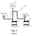
- Fig. 1 is a schematic illustration of a battery operated system 11 according to prior art. It is here assumed that the system 11 is installed in a vehicle such as a recreational vehicle, a car, an ambulance or a boat.
- the system comprises an alternator 12 and a starter battery 16 which is adapted to charge a battery 13 when its engine is running.
- a number of consumers 14 of electrical energy are connected to the battery 13, and a number of consumers 17 could also be connected to the starter battery 16.
- the consumers 14 and 17 represent the electrical system of the vehicle.
- the system 11 also comprises a battery separator device 15 which separates the starter battery 16 and the battery 13 when the alternator is not running.
- the battery separator device 15 could be implemented with relays, diodes, transistors, switches or other devices. The current that goes through the battery separator device 15 to the battery 13 and the consumers 14 have the same voltage, which could restrict the efficiency of the charging of the battery 13.
- a basic idea of the present invention is to allow for improved efficiency in the charging of the battery 13 by providing a possibility to separate charging and consumption.
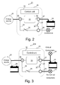
- Fig. 2 is a schematic block diagram illustrating a battery operated system 21 according to an embodiment of the present invention.
- the system 21 comprises an energy source 22, which for instance may be an alternator, a solar or wind generator or a generator connected to an engine of a vehicle.
- the energy source can provide charging current to a battery 23 and electrical energy to a number of consumers 24 when it is in an on state (e.g. when the engine is running in case the energy source 22 is an alternator in a vehicle).
- the system 21 also comprises a battery charging and electrical energy delivery system 25 comprising a first connection 26 for connection to the energy source 22, a second connection 27 for connection to the battery 23 and a third connection 28 for connection to the consumer(s) 24.
- the delivery system 25 also includes a first path 29 extending between the first and second connections 26, 27 for supplying electrical energy from the energy source 22 to the battery 23 for charging the same.
- a second path 30 extends between the first connection 26 and the third connection 28 for supplying electrical energy from the energy source 22 to the consumer(s) 24.
- a third path 31 is provided between the second and third connections 27, 28 for conducting electrical energy from the battery 23 to the consumer(s) 24.
- a control unit 32 is adapted to control the supply of electrical energy along the first, second and third paths 29-31. By disconnecting the third path it is possible to separate the supply of electrical energy between the energy source 22 and the consumers 24 from the supply of electrical energy between the energy source 22 and the battery 23, thus separating charging and consumption.
- the number of consumers 24 (or “set of consumers” 24) is intended to encompass scenarios with a single consumer of electrical energy as well as scenarios with a plurality of consumers.
- the control unit is 32 is provided with means for detecting a state of the energy source 22 and control the supply of electrical energy along the paths 29, 30, 31 in response to the detected state.
- the control unit 32 is adapted to connect the first and second paths 29, 30 and disconnect the third path 31. Thereby the battery 23 is charged via the first path 29 and the consumers 24 are powered by the energy source 22 via the second path 30.
- the control unit 32 connects the third path 31 so that the consumers 24 are powered by the battery 23 via the third path 31.
- each path may be provided with a relay 33, 35, 36 for connecting or disconnecting the path.
- the first path is provided with a device 33.
- the device 33 may e.g. be a relay, a DC/DC-charger or a relay and a DC/DC-charger in parallel. If a DC/DC-charger is provided it is preferably an intelligent charger that is able to monitor the battery state and control the charging to achieve efficient charging and battery care.
- control unit 32 may detect the state of the energy source 22 as will be appreciated by a person skilled in the art.
- the control unit 32 may e.g. be adapted to monitor the voltage level at the first connection 26. If a voltage level above a predetermined threshold level is detected, it may be interpreted as the energy source 22 being on (i.e. that the engine is running in case the energy source 22 is an alternator of a vehicle). If the voltage level drops below a certain level, it may be interpreted as the energy source being off (the engine has been turned off in the vehicle example).
- the delivery system 25 may include a voltage sensitive relay that engages when e.g. a voltage level of 13.7 volts is reached, thus connecting the first and second paths 29, 30.
- the voltage sensitive relay When the voltage drops below e.g. 12.8 volts the voltage sensitive relay disengages, thus disconnecting the first and second paths 29, 30 and connecting the third path 31.
- Other ways of monitoring the state of the energy source include monitoring a charging indicator such as a lamp or information screen. If the energy source 22 is an alternator, a charging indicator is normally connected to a D+-output of the alternator.
- the control unit 32 may be adapted to apply a certain delay before connecting or disconnecting the consumers 24 from the battery 23 in case a state change of the energy source 22 is detected, e.g. a 5 second delay after detecting a state change from off to on and a 10 second delay after detecting a state change from on to off.
- a certain delay e.g. a 5 second delay after detecting a state change from off to on and a 10 second delay after detecting a state change from on to off.
- a purpose of using such a delayed mode switch is to avoid that short temporary voltage peaks/dips could cause the delivery system 25 to switch mode.
- the control unit 32 may furthermore be adapted to monitor the battery 23 and protect it from being too discharged by disconnecting the third path 31 in case a voltage level of the battery 23 drops below a predetermined state of charge threshold, thus disconnecting the consumers 24 from the battery 23.
- Fig. 3 illustrates another embodiment of a battery operated system 21a according to the present invention, which is similar to the system 21 in Fig. 2 apart from there being provided two sets of consumers 24 and 34.
- the set of consumers 24 is a number of non-critical consumers connected to the third connection 28, while the set of consumers 34 is a number of critical consumers directly connected to the battery 23.
- Critical consumers are electrical equipment which should not bee disconnected even if the battery is becoming seriously discharged, while non-critical consumers usually are additional equipment which can be disconnected without affecting the main function of the system 21a.
- the system 21a is included in a boat critical consumers may be a bilge pump, emergency light and navigation system e.g., while non-critical consumers may be a refrigerator, lamps, heating and fans.
- the set of critical consumers 34 is unaffected.
- the benefits of this arrangement can be easily appreciated.
- the set of non-critical consumers 24 is completely separated from the battery 23 during charging, which makes it possible to achieve more efficient charging of the battery.
- critical consumers 34 are given priority when the battery 23 is becoming seriously discharged and the energy source 22 is off by making it possible to cut the power supply to non-critical consumers.
- a second battery such as a starter battery 38 may be connected to the first connection 26.
- the control unit 32 may be adapted to monitor the voltage at the first connection 26 and at the second connection 27. If it is detected that the state of charge (SOC) of the starter battery has dropped below a certain limit, while the voltage of the battery 23 is higher, electrical energy could be transferred from connection 27 to connection 26 by closing the first path 29 through device 33. Thus it is possible to achieve maintenance charging of the starter battery 38 under the control of the control unit 32.
- a starter battery is often given priority in battery operated systems and by allowing for charging of the starter battery by the battery 23 situations where the starter battery become too discharged may be avoided.
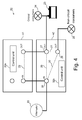
- Fig. 4 is a schematic block diagram of how a battery operated system 40 according to the invention (such as the one shown in fig. 3 ) can be implemented using two separate units 41 and 42.
- the unit 41 is an intelligent DC/DC-charger and the unit 42 is a battery switch, comprising the first, second and third connections 26-28 discussed above.
- Each unit 41, 42 is provided with a housing, and closing links are used to connect the different ports on the units as illustrated in Fig. 4 .
- the units 41 and 42 each include a control unit 32a and 32b respectively.
- the control units 32a and 32b comprise functionality which all in all corresponds to the control unit 32 in Fig. 2 and Fig. 3 .
- Fig. 5 illustrates a method of controlling the system 40.
- the operation scenario includes consecutive scenes a)-f), which are described merely as examples to illustrate how the system 40 may operate. It should especially be noted that all numeric specifications of time, voltage/current levels, limits and thresholds are merely examples. Other levels, limits and thresholds may be applied in other embodiments.
- the scenes are as follows:
- control unit 32 can be implemented as a single unit or divided into several units. It is possible for the control unit to be a separate unit or integrated into and distributed over other components in the delivery system 25.
- control unit is rather to be understood as the collective function of controlling the electrical energy supply on the first, second and third paths.
- the control unit may be implemented using e.g. one or several microprocessors or using discrete circuits as will be understood by the person skilled in the art.
- FIG. specification there have been disclosed typical preferred embodiments of the invention and, although specific terms are employed, they are used in a generic and descriptive sense only and not for purposes of limitation, the scope of the invention being set forth in the following claims.
Abstract
Description
- The present invention relates to the a battery charging and electrical energy delivery system for delivering electrical energy to consumers and charging current to a battery and also to a battery operated system comprising such a battery charging and electrical energy delivery system.
- Vehicles such as boats and motor homes are usually provided with several different types of consumers of electrical energy, such as lamps, refrigerators, bilge pumps, navigation equipment, cooking equipment and other types of electrical equipment. A re-chargeable lead-acid service battery is often provided to supply the different consumers with electrical energy. In order to ensure proper operation of all the electrical equipment in the vehicle the battery should be charged regularly. Charging arrangements can be provided so that when the engine of the vehicle is running the battery is charged.
- There are many aspects to consider in order to prolong the service life and retain the performance of the battery. The battery may remain idle for long periods e.g. during the winter time in the case of a boat. During the summer time the battery may instead be put under a lot of strain by the electrical equipment installed in the vehicle and may be used very frequently without the engine being turned on. This is naturally very taxing for the battery.
- In the 1990s, battery charging underwent a robust period of development, which introduced a new type of maintenance and care, wherein focus was put on efficient charging the battery in such a way that the service life of the battery was prolonged and such that the battery could provide the maximum performance for all of this time. Multi-stage charging as disclosed in the
U.S. patent 7,541,778 provides such efficient battery charging. - Nowadays people have come to rely on everything working properly to ensure that they have the time to do everything they have planned. Therefore, people's expectations and requirements on all the vehicles around them have increased. Correct battery care can avert many disappointments and problems. People also have different expectations and requirements on different types of electrical equipment in the vehicle. While it may be somewhat annoying if the refrigerator is not working in the boat, a bilge pump unable to operate may lead to a really hazardous situation.
- There's a built-in conflict between battery charge and load use voltage. The charge voltage for a battery depends on the temperature and should normally be at about 14.4V at 25 degrees C. A cold battery should with preference be charged at a higher voltage and a warm at a lower voltage. 12V consumers like light bulbs, electronics and LED light have significantly longer expected life if the voltage is lower. Typically the expected life of a light bulb is reduced by 50% if the voltage is increased 5%.
- Consequently there are several different needs and requirements with respect to electrical energy consumption to consider in a vehicle. The battery has certain demands that need to be fulfilled in order to achieve efficient charging that differ from the demands of other electrical equipment. Furthermore there are different expectations and requirements on different types of electrical equipment as explained above. It is thus a challenging problem how to supply electrical energy to consumers and for charging the battery and at the same time fulfill differing demands and requirements.
- An object of the present invention is to provide means that allow for delivery of electrical energy to facilitate efficient charging of a battery and supply of electrical energy to a number of consumers.
- The above stated object is achieved by means of a battery charging and electrical energy delivery system and a battery operated system according to the independent claims.
- A first embodiment of the present invention provides a battery charging and electrical energy delivery system. The delivery system comprises a first connection for connection to an energy source, a second connection for connection to a battery and a third connection for connection to a first set of consumers of electrical energy. The delivery system also comprises a first path for supplying charging current from the energy source to the battery when connected to the first and second connections respectively. A second path, separate from the first path, is also provided for supplying electrical energy from the energy source to the first set of consumers when connected to the first and third connections respectively. Furthermore a third path is provided for supplying electrical energy from the battery to the first set of consumers when connected to the second and third connections respectively. The deliver system includes a control unit (32) for controlling the supply of electrical energy along the first, second and third paths in response to a detected state of the energy source.
- A second embodiment of the present invention provides a battery operated system comprising a battery charging and electrical energy delivery system as described above, as well as an energy source connected to the first connection, a battery connected to the second connection, and a first set of consumers connected to the third connection.
- An advantage of embodiments of the present invention is that they allow for separation of charging of a battery and supply of electrical energy to a number of consumers. Thereby it is possible to provide more efficient charging of the battery.
- Another advantage of certain embodiments of the present invention is improved battery protection can be provided by disconnecting non-critical consumers from the battery in cases where the battery is becoming seriously discharged.
- Another advantage of certain embodiments of the present invention is improved charging of a starter battery from a service battery. The starter battery has usually priority in a system. Energy could be transferred from a service battery to the starter battery.
- These and other advantages with, and aspects of, the present invention will become apparent from the following detailed description and from the accompanying drawings.
- In the following description of an embodiment of the invention, reference will be made to the accompanying drawings of which:
-
Fig. 1 is a schematic block diagram of a battery operated system with a battery charging and electrical energy delivery system according to prior art. -
Fig. 2 is a schematic block diagram of a battery operated system with a battery charging and electrical energy delivery system according to an embodiment of the present invention. -
Fig. 3 is a schematic block diagram of a battery operated system with a battery charging and electrical energy delivery system according to another embodiment of the present invention -
Fig. 4 is a schematic block diagram of yet another embodiment of a battery charging and electrical energy delivery system according to the present invention. -
Fig. 5 is a flow diagram of a method of controlling delivery of electrical energy to a number of consumers and for charging a battery. - The present invention will now be described more fully hereinafter with reference to the accompanying drawings, in which preferred embodiments of the invention are shown. This invention may, however, be embodied in many different forms and should not be construed as limited to the embodiments set forth herein; rather, these embodiments are provided so that this disclosure will be thorough and complete, and will fully convey the scope of the invention to those skilled in the art. In the drawings, like reference signs refer to like elements.
-
Fig. 1 is a schematic illustration of a battery operatedsystem 11 according to prior art. It is here assumed that thesystem 11 is installed in a vehicle such as a recreational vehicle, a car, an ambulance or a boat. The system comprises analternator 12 and astarter battery 16 which is adapted to charge abattery 13 when its engine is running. A number ofconsumers 14 of electrical energy are connected to thebattery 13, and a number ofconsumers 17 could also be connected to thestarter battery 16. Theconsumers system 11 also comprises abattery separator device 15 which separates thestarter battery 16 and thebattery 13 when the alternator is not running. Thebattery separator device 15 could be implemented with relays, diodes, transistors, switches or other devices. The current that goes through thebattery separator device 15 to thebattery 13 and theconsumers 14 have the same voltage, which could restrict the efficiency of the charging of thebattery 13. - A basic idea of the present invention is to allow for improved efficiency in the charging of the
battery 13 by providing a possibility to separate charging and consumption. -
Fig. 2 is a schematic block diagram illustrating a battery operatedsystem 21 according to an embodiment of the present invention. Thesystem 21 comprises anenergy source 22, which for instance may be an alternator, a solar or wind generator or a generator connected to an engine of a vehicle. The energy source can provide charging current to abattery 23 and electrical energy to a number ofconsumers 24 when it is in an on state (e.g. when the engine is running in case theenergy source 22 is an alternator in a vehicle). Thesystem 21 also comprises a battery charging and electricalenergy delivery system 25 comprising afirst connection 26 for connection to theenergy source 22, asecond connection 27 for connection to thebattery 23 and athird connection 28 for connection to the consumer(s) 24. Thedelivery system 25 also includes afirst path 29 extending between the first andsecond connections energy source 22 to thebattery 23 for charging the same. Asecond path 30 extends between thefirst connection 26 and thethird connection 28 for supplying electrical energy from theenergy source 22 to the consumer(s) 24. Furthermore athird path 31 is provided between the second andthird connections battery 23 to the consumer(s) 24. Acontrol unit 32 is adapted to control the supply of electrical energy along the first, second and third paths 29-31. By disconnecting the third path it is possible to separate the supply of electrical energy between theenergy source 22 and theconsumers 24 from the supply of electrical energy between theenergy source 22 and thebattery 23, thus separating charging and consumption. - In this description it should be noted that throughout this description "the number of consumers" 24 (or "set of consumers" 24) is intended to encompass scenarios with a single consumer of electrical energy as well as scenarios with a plurality of consumers.
- The control unit is 32 is provided with means for detecting a state of the
energy source 22 and control the supply of electrical energy along thepaths energy source 22 is on thecontrol unit 32 is adapted to connect the first andsecond paths third path 31. Thereby thebattery 23 is charged via thefirst path 29 and theconsumers 24 are powered by theenergy source 22 via thesecond path 30. When theenergy source 22 is off thecontrol unit 32 connects thethird path 31 so that theconsumers 24 are powered by thebattery 23 via thethird path 31. - According to one embodiment each path may be provided with a
relay Fig. 2 it is illustrated that the first path is provided with adevice 33. Thedevice 33 may e.g. be a relay, a DC/DC-charger or a relay and a DC/DC-charger in parallel. If a DC/DC-charger is provided it is preferably an intelligent charger that is able to monitor the battery state and control the charging to achieve efficient charging and battery care. - There are several different ways in which the
control unit 32 may detect the state of theenergy source 22 as will be appreciated by a person skilled in the art. Thecontrol unit 32 may e.g. be adapted to monitor the voltage level at thefirst connection 26. If a voltage level above a predetermined threshold level is detected, it may be interpreted as theenergy source 22 being on (i.e. that the engine is running in case theenergy source 22 is an alternator of a vehicle). If the voltage level drops below a certain level, it may be interpreted as the energy source being off (the engine has been turned off in the vehicle example). According an embodiment of the invention thedelivery system 25 may include a voltage sensitive relay that engages when e.g. a voltage level of 13.7 volts is reached, thus connecting the first andsecond paths second paths third path 31. Other ways of monitoring the state of the energy source include monitoring a charging indicator such as a lamp or information screen. If theenergy source 22 is an alternator, a charging indicator is normally connected to a D+-output of the alternator. - The
control unit 32 may be adapted to apply a certain delay before connecting or disconnecting theconsumers 24 from thebattery 23 in case a state change of theenergy source 22 is detected, e.g. a 5 second delay after detecting a state change from off to on and a 10 second delay after detecting a state change from on to off. A purpose of using such a delayed mode switch is to avoid that short temporary voltage peaks/dips could cause thedelivery system 25 to switch mode. - The
control unit 32 may furthermore be adapted to monitor thebattery 23 and protect it from being too discharged by disconnecting thethird path 31 in case a voltage level of thebattery 23 drops below a predetermined state of charge threshold, thus disconnecting theconsumers 24 from thebattery 23. -
Fig. 3 illustrates another embodiment of a battery operatedsystem 21a according to the present invention, which is similar to thesystem 21 inFig. 2 apart from there being provided two sets ofconsumers consumers 24 is a number of non-critical consumers connected to thethird connection 28, while the set ofconsumers 34 is a number of critical consumers directly connected to thebattery 23. Critical consumers are electrical equipment which should not bee disconnected even if the battery is becoming seriously discharged, while non-critical consumers usually are additional equipment which can be disconnected without affecting the main function of thesystem 21a. If thesystem 21a is included in a boat critical consumers may be a bilge pump, emergency light and navigation system e.g., while non-critical consumers may be a refrigerator, lamps, heating and fans. If the third path is disconnected to protect thebattery 23 from being too discharged the set ofcritical consumers 34 is unaffected. The benefits of this arrangement can be easily appreciated. The set ofnon-critical consumers 24 is completely separated from thebattery 23 during charging, which makes it possible to achieve more efficient charging of the battery. At the same time it can be ensured thatcritical consumers 34 are given priority when thebattery 23 is becoming seriously discharged and theenergy source 22 is off by making it possible to cut the power supply to non-critical consumers. - In
Fig. 3 it is furthermore illustrated that a second battery, such as astarter battery 38 may be connected to thefirst connection 26. Thecontrol unit 32 may be adapted to monitor the voltage at thefirst connection 26 and at thesecond connection 27. If it is detected that the state of charge (SOC) of the starter battery has dropped below a certain limit, while the voltage of thebattery 23 is higher, electrical energy could be transferred fromconnection 27 toconnection 26 by closing thefirst path 29 throughdevice 33. Thus it is possible to achieve maintenance charging of thestarter battery 38 under the control of thecontrol unit 32. A starter battery is often given priority in battery operated systems and by allowing for charging of the starter battery by thebattery 23 situations where the starter battery become too discharged may be avoided. -
Fig. 4 is a schematic block diagram of how a battery operatedsystem 40 according to the invention (such as the one shown infig. 3 ) can be implemented using twoseparate units unit 41 is an intelligent DC/DC-charger and theunit 42 is a battery switch, comprising the first, second and third connections 26-28 discussed above. Eachunit Fig. 4 . - In
Fig. 4 it is illustrated that theunits control unit control units control unit 32 inFig. 2 and Fig. 3 . - Now an operation scenario will be described in connection with a flow diagram shown in
Fig. 5 , which illustrates a method of controlling thesystem 40. In this operation scenario it is assumed that thesystem 40 is installed in a boat and that the energy source is an alternator connected to the boat engine. The operation scenario includes consecutive scenes a)-f), which are described merely as examples to illustrate how thesystem 40 may operate. It should especially be noted that all numeric specifications of time, voltage/current levels, limits and thresholds are merely examples. Other levels, limits and thresholds may be applied in other embodiments. The scenes are as follows: - a) The engine is off. The
control unit 32 checks the state of theenergy source 22 in astep 51. The voltage level at thefirst connection 26 is below 13.7V which in this example is interpreted as the engine being off. Thenon-critical consumers 24 are powered by thebattery 23 via thethird path 31, e.g. by means of a 10A current at 12.4 V (step 52). Thecontrol unit 32 may also monitor that thebattery 23 does not become too discharged in anoptional step 53. b) The engine starts. The voltage at thefirst connection 26 rises to 13.8V which thecontrol unit 32 detects as theenergy source 22 being on (step 51). However in this scenario there is a 5 second delay before the DC/DC-charger 41 starts and before thebattery switch 42 reacts. - c) 5 seconds after the engine has started, the non-critical consumers are supplied with electrical energy from the
alternator 22, in this example 10A current at 13.8V (step 55). Thebattery 23 is charged with the DC/DC-charger 41 at a maximum of 20A according to this example scenario (step 55). However it is also possible to lead a current of e.g. 30A through thebattery switch 42 in parallel with the 20A through the DC/DC-charger 41 so that battery receives 50A from theenergy source 22 and a total current of 60A is drawn from the energy source (10A to the set ofnon-critical consumers 24 + 50A to the battery 23). - d) The engine is turned off. This is detected by the control unit detecting that the voltage level drops below 12.8V at the first connection 26 (step 51). There is a 10 second delay before the
units - e) After 10 seconds, the non-critical consumers (24) are then again powered by the battery 23 (step 52).
- f) The voltage level at the battery (23) has dropped to 11.6V which is a predetermined state of charge threshold that indicates that the battery has reached a critical level and is becoming too discharged. This state is detected by the
control unit 32 instep 53, and thenon-critical consumers 24 are disconnected from the battery in astep 54. However the critical consumers are still powered from thebattery 23. - From the different embodiments it has been shown that the
control unit 32 can be implemented as a single unit or divided into several units. It is possible for the control unit to be a separate unit or integrated into and distributed over other components in thedelivery system 25. The term control unit is rather to be understood as the collective function of controlling the electrical energy supply on the first, second and third paths. The control unit may be implemented using e.g. one or several microprocessors or using discrete circuits as will be understood by the person skilled in the art. In the drawings and specification, there have been disclosed typical preferred embodiments of the invention and, although specific terms are employed, they are used in a generic and descriptive sense only and not for purposes of limitation, the scope of the invention being set forth in the following claims.
Claims (16)
- A battery charging and electrical energy delivery system (25) comprising a first connection (26) for connection to an energy source;
a second connection (27) for connection to a battery (23);
a third connection (28) for connection to a first set of consumers (24) of electrical energy;
a first path (29) for supplying charging current from the energy source to the battery when connected to the first and second connections (26, 27) respectively;
a second path (30), separate from said first path, for supplying electrical energy from the energy source to the first set of consumers (24) when connected to the first and third connections (26, 28) respectively;
a third path (31) for supplying electrical energy from the battery to the first set of consumers (24) when connected to the second and third connections (27, 28) respectively;
a control unit (32) for controlling the supply of electrical energy along said first, second and third paths in response to a detected state of the energy source. - The battery charging and electrical energy delivery system (25) according to claim 1, wherein the control unit (32) is adapted to detect the state of the energy source (22) by monitoring a voltage level in relation to a predetermined threshold level, or by monitoring a charging indicator.
- The battery charging and electrical energy delivery system (25) according to claim 1 or 2, wherein the control unit (32) is adapted to control the supply of electrical energy along said first, second and third paths (29, 30, 31) such that
the battery (23) is charged via the first path (29) and the first set of consumers (24) receives electrical energy via the second path (30), in response to detecting that the energy source (22) is on; and
the first set of consumers (24) receives electrical energy via the third path (31), in response to detecting that the energy source (22) is off. - The battery charging and electrical energy delivery system (25) according to claim 3, wherein the control unit (32) is adapted to switch the supply of electrical energy to the first set of consumers (24) from supply via the third path (31) to supply via the second path (30) in response to detecting a state change of the energy source (22) from off to on and that the on state is maintained for a predetermined first period of time.
- The battery charging and electrical energy delivery system (25) according to claim 3 or 4, wherein the control unit (32) is adapted to switch the supply of electrical energy to the first set of consumers (24) from supply via the second path (30) to supply via the third path (31) in response to detecting a state change of the energy source (22) from on to off and that the off state is maintained for a predetermined second period of time.
- The battery charging and electrical energy delivery system (25) according to any of claims 1-5, further comprising a device (33) on the first path (29) which is adapted to break or connect the supply of charging current along the first path.
- The battery charging and electrical energy delivery system (25) according to claim 6, wherein said device (33) is a first relay.
- The battery charging and electrical energy delivery system (25) according to claim 6, wherein said device (33) comprises a DC/DC charger.
- The battery charging and electrical energy delivery system (25) according to claim 6, wherein said device (33) comprises a DC/DC charger in parallel with a relay.
- The battery charging and electrical energy delivery system (25) according to any of claims 1-9, comprising a second relay 35 and third relay 36 adapted to break or connect the supply of electrical energy along the second and third paths respectively.
- The battery charging and electrical energy delivery system (25) according to any of claims 1-10, wherein the control unit (32) is further adapted to monitor a state of charge of the battery (23) when connected to the second connection (27) and to break supply of electrical energy (22) to the first set of consumers (24) if the state of charge drops below a predetermined state of charge threshold.
- The battery charging and electrical energy delivery system (25) according to any of claims 1-11, wherein the control unit (32) is adapted to monitor a state of charge of a second battery (38) when connected to the first connection (26) and to control the flow of electrical energy on the first path (29) to transfer electrical energy from the second connection (27) to the first connection (26) to charge the second battery (38).
- A battery operated system (21, 21a, 40) comprising
a battery charging and electrical energy delivery system (25) according to any of claims 1-11,
an energy source (22) connected to the first connection (26), a battery (23) connected to the second connection (27), and a first set of consumers (24) connected to the third connection (28). - The battery operated system (21, 21a, 40) according to claim 13,
wherein the energy source (22) is an alternator, photovoltaic panel, wind generator or generator. - The battery operated system (21a, 40) according to claim 13 or 14, further comprising a second set of consumers (34) directly connected to the battery (23) to receive electrical energy from the battery (23) independently of the battery charging and electrical energy delivery system (25).
- The battery operated system (21a, 40) according to claim 15, wherein said first set of consumers (24) are non-critical consumers and said second set of consumers (34) are critical consumers, wherein a non-critical consumer is a consumer that could be disconnected in case the battery (23) is discharged below the predetermined state of charge threshold and wherein a critical consumer is a consumer that should not be disconnected if the battery (23) is discharged below the predetermined state of charge threshold.
Priority Applications (2)
| Application Number | Priority Date | Filing Date | Title |
|---|---|---|---|
| EP09170640.8A EP2299556B1 (en) | 2009-09-18 | 2009-09-18 | Battery charging and electrical energy delivery system and battery operated system |
| US12/564,360 US8350535B2 (en) | 2009-09-18 | 2009-09-22 | Battery charging and electrical energy delivery system for delivering electrical energy to consumers and charging current to a battery and a battery operated system |
Applications Claiming Priority (1)
| Application Number | Priority Date | Filing Date | Title |
|---|---|---|---|
| EP09170640.8A EP2299556B1 (en) | 2009-09-18 | 2009-09-18 | Battery charging and electrical energy delivery system and battery operated system |
Publications (2)
| Publication Number | Publication Date |
|---|---|
| EP2299556A1 true EP2299556A1 (en) | 2011-03-23 |
| EP2299556B1 EP2299556B1 (en) | 2019-07-03 |
Family
ID=42109985
Family Applications (1)
| Application Number | Title | Priority Date | Filing Date |
|---|---|---|---|
| EP09170640.8A Active EP2299556B1 (en) | 2009-09-18 | 2009-09-18 | Battery charging and electrical energy delivery system and battery operated system |
Country Status (2)
| Country | Link |
|---|---|
| US (1) | US8350535B2 (en) |
| EP (1) | EP2299556B1 (en) |
Cited By (2)
| Publication number | Priority date | Publication date | Assignee | Title |
|---|---|---|---|---|
| CN114421561A (en) * | 2021-12-31 | 2022-04-29 | 深圳市驰普科达科技有限公司 | Charging method and outdoor energy storage equipment |
| EP3394422B1 (en) * | 2015-12-21 | 2024-02-14 | Volvo Truck Corporation | Control method of the power management system in a vehicle provided with two batteries |
Families Citing this family (10)
| Publication number | Priority date | Publication date | Assignee | Title |
|---|---|---|---|---|
| US8452490B2 (en) * | 2009-12-14 | 2013-05-28 | Control Solutions LLC | Electronic circuit for charging and heating a battery |
| CN102420440B (en) * | 2010-09-27 | 2014-08-13 | 比亚迪股份有限公司 | Vehicle-mounted solar charger control system and method |
| JP6061739B2 (en) * | 2013-03-12 | 2017-01-18 | アルパイン株式会社 | Power supply device, in-vehicle electronic system, booster circuit control program, and booster circuit control method |
| TWI489734B (en) * | 2013-12-20 | 2015-06-21 | 緯創資通股份有限公司 | Charge devices and charge systems |
| US10052965B2 (en) * | 2014-09-30 | 2018-08-21 | Ford Global Technologies, Llc | Method for charging the starter battery of a vehicle |
| JP6595785B2 (en) * | 2015-03-31 | 2019-10-23 | 株式会社Subaru | Vehicle power supply |
| KR20170037260A (en) * | 2015-09-25 | 2017-04-04 | 현대자동차주식회사 | Battery Management System for vehicle and controlling method thereof |
| JP6468371B2 (en) * | 2016-01-12 | 2019-02-13 | 日産自動車株式会社 | Power supply system and control method thereof |
| JP2017124800A (en) * | 2016-01-15 | 2017-07-20 | 株式会社東芝 | Power supply device |
| US11336111B2 (en) * | 2018-06-08 | 2022-05-17 | Powin, Llc | Microgrid power system |
Citations (9)
| Publication number | Priority date | Publication date | Assignee | Title |
|---|---|---|---|---|
| EP0623985A1 (en) * | 1993-05-05 | 1994-11-09 | Sgs-Thomson Microelectronics Pte Ltd. | Power Sharing detector |
| US6037749A (en) * | 1995-06-21 | 2000-03-14 | Batteryguard Limited | Battery monitor |
| DE10262000A1 (en) * | 2002-07-12 | 2004-02-26 | Audi Ag | On-board vehicle electrical system has 2 voltage levels coupled by coupling device, regulating device that controls longitudinal regulator taking into account future load on second voltage level |
| US20040113585A1 (en) * | 2001-08-17 | 2004-06-17 | Stanesti Vlad Popescu | Charging circuit for parallel charging in multiple battery systems |
| US20050151517A1 (en) * | 2004-01-14 | 2005-07-14 | Alexandre Cook | Power management system for vehicles |
| US20050279544A1 (en) * | 2004-05-10 | 2005-12-22 | Volkswagen Ag | Electrical energy system in a hybrid car |
| US20060080051A1 (en) * | 2004-10-13 | 2006-04-13 | Dell Products L.P. | Power management scheme for external batteries |
| US20080191555A1 (en) * | 2007-02-09 | 2008-08-14 | Samsung Electronics Co., Ltd. | Computer and power supply method thereof |
| US7541778B2 (en) | 2003-04-30 | 2009-06-02 | Creator Teknisk Utveckling Ab | Method and apparatus for detecting whether a lead acid battery is sulphated and for charging same |
Family Cites Families (11)
| Publication number | Priority date | Publication date | Assignee | Title |
|---|---|---|---|---|
| JPH0195574U (en) * | 1987-12-15 | 1989-06-23 | ||
| JP2000032684A (en) * | 1998-07-08 | 2000-01-28 | Toyota Autom Loom Works Ltd | Charging circuit and method therefor |
| US6476519B1 (en) * | 2000-04-06 | 2002-11-05 | Marconi Communications, Inc. | Power back-up unit with low voltage disconnects that provide load shedding |
| US20040145348A1 (en) | 2000-09-21 | 2004-07-29 | Constantin Bucur | Power management topologies |
| US6608396B2 (en) * | 2001-12-06 | 2003-08-19 | General Motors Corporation | Electrical motor power management system |
| US6833686B2 (en) * | 2003-02-21 | 2004-12-21 | Research In Motion Limited | Circuit and method of operation for an adaptive charge rate power supply |
| JP3764429B2 (en) * | 2003-02-28 | 2006-04-05 | 株式会社東芝 | Electronic device and power supply switching control method for electronic device |
| KR100576234B1 (en) * | 2004-04-28 | 2006-05-03 | 삼성전자주식회사 | Electronic device |
| CN100372212C (en) * | 2005-08-16 | 2008-02-27 | 信邦电子股份有限公司 | Power supply storage equipment of possessing outputted voltages in multiple stages |
| JP4673252B2 (en) * | 2006-05-17 | 2011-04-20 | ローム株式会社 | Battery charging circuit, portable electronic device, and semiconductor integrated circuit |
| US7764050B2 (en) * | 2007-01-02 | 2010-07-27 | Intersil Americas Inc. | System and method of charging a battery and power delivery using an adapter and capacitor voltage divider |
-
2009
- 2009-09-18 EP EP09170640.8A patent/EP2299556B1/en active Active
- 2009-09-22 US US12/564,360 patent/US8350535B2/en active Active
Patent Citations (9)
| Publication number | Priority date | Publication date | Assignee | Title |
|---|---|---|---|---|
| EP0623985A1 (en) * | 1993-05-05 | 1994-11-09 | Sgs-Thomson Microelectronics Pte Ltd. | Power Sharing detector |
| US6037749A (en) * | 1995-06-21 | 2000-03-14 | Batteryguard Limited | Battery monitor |
| US20040113585A1 (en) * | 2001-08-17 | 2004-06-17 | Stanesti Vlad Popescu | Charging circuit for parallel charging in multiple battery systems |
| DE10262000A1 (en) * | 2002-07-12 | 2004-02-26 | Audi Ag | On-board vehicle electrical system has 2 voltage levels coupled by coupling device, regulating device that controls longitudinal regulator taking into account future load on second voltage level |
| US7541778B2 (en) | 2003-04-30 | 2009-06-02 | Creator Teknisk Utveckling Ab | Method and apparatus for detecting whether a lead acid battery is sulphated and for charging same |
| US20050151517A1 (en) * | 2004-01-14 | 2005-07-14 | Alexandre Cook | Power management system for vehicles |
| US20050279544A1 (en) * | 2004-05-10 | 2005-12-22 | Volkswagen Ag | Electrical energy system in a hybrid car |
| US20060080051A1 (en) * | 2004-10-13 | 2006-04-13 | Dell Products L.P. | Power management scheme for external batteries |
| US20080191555A1 (en) * | 2007-02-09 | 2008-08-14 | Samsung Electronics Co., Ltd. | Computer and power supply method thereof |
Cited By (2)
| Publication number | Priority date | Publication date | Assignee | Title |
|---|---|---|---|---|
| EP3394422B1 (en) * | 2015-12-21 | 2024-02-14 | Volvo Truck Corporation | Control method of the power management system in a vehicle provided with two batteries |
| CN114421561A (en) * | 2021-12-31 | 2022-04-29 | 深圳市驰普科达科技有限公司 | Charging method and outdoor energy storage equipment |
Also Published As
| Publication number | Publication date |
|---|---|
| US20110068749A1 (en) | 2011-03-24 |
| US8350535B2 (en) | 2013-01-08 |
| EP2299556B1 (en) | 2019-07-03 |
Similar Documents
| Publication | Publication Date | Title |
|---|---|---|
| US8350535B2 (en) | Battery charging and electrical energy delivery system for delivering electrical energy to consumers and charging current to a battery and a battery operated system | |
| CA2568875C (en) | System and method for electrical energy switching and control in a vehicle | |
| US10710469B2 (en) | Automotive dual voltage battery charging system | |
| US8823206B2 (en) | Power-supply control device | |
| US10661877B2 (en) | Electric drive for a vehicle | |
| EP2899058B1 (en) | Vehicle control system, vehicle information supply device, and vehicle information supply method | |
| WO2014156041A1 (en) | Power supply system and charging and discharging control method for power supply system | |
| CN106660502B (en) | Automotive power supply system | |
| CN104467061B (en) | Electric control system and method for vehicle electrical power socket | |
| KR20120012661A (en) | Apparatus for battery control and method for battery control for electrical vehicles | |
| WO2007096720A1 (en) | Electrically driven vehicle | |
| JP2008072880A (en) | Power supply system | |
| CN102343877A (en) | Low voltage bus stability | |
| SE537378C2 (en) | Battery power management system | |
| JP2003200795A (en) | Method and arrangement for supplying quiescent current to vehicle with multiple voltage on-board electric system | |
| CN107399287B (en) | Vehicle power system for boost start | |
| US20170298890A1 (en) | Systems and methods for uninterruptable power supply | |
| US9327612B2 (en) | Emergency power supply system for fuel cell-powered vehicle | |
| CN110091815B (en) | Power system for autonomous vehicle | |
| KR101546046B1 (en) | System for preventing battery discharge of electric power cart and method thereof | |
| CN104410145B (en) | A kind of electric air-conditioning power-supply system | |
| CN110758102A (en) | Electric automobile control device and electric automobile | |
| JP2017056853A (en) | Vehicular power supply control device, and control method of vehicular power supply control device | |
| GB2395376A (en) | Energy management | |
| WO2016075616A2 (en) | Aid module for electrically starting an internal combustion engine |
Legal Events
| Date | Code | Title | Description |
|---|---|---|---|
| PUAI | Public reference made under article 153(3) epc to a published international application that has entered the european phase |
Free format text: ORIGINAL CODE: 0009012 |
|
| AK | Designated contracting states |
Kind code of ref document: A1 Designated state(s): AT BE BG CH CY CZ DE DK EE ES FI FR GB GR HR HU IE IS IT LI LT LU LV MC MK MT NL NO PL PT RO SE SI SK SM TR |
|
| RAP1 | Party data changed (applicant data changed or rights of an application transferred) |
Owner name: CTEK SWEDEN AB |
|
| 17P | Request for examination filed |
Effective date: 20110922 |
|
| STAA | Information on the status of an ep patent application or granted ep patent |
Free format text: STATUS: EXAMINATION IS IN PROGRESS |
|
| 17Q | First examination report despatched |
Effective date: 20170124 |
|
| GRAP | Despatch of communication of intention to grant a patent |
Free format text: ORIGINAL CODE: EPIDOSNIGR1 |
|
| STAA | Information on the status of an ep patent application or granted ep patent |
Free format text: STATUS: GRANT OF PATENT IS INTENDED |
|
| INTG | Intention to grant announced |
Effective date: 20190408 |
|
| RIN1 | Information on inventor provided before grant (corrected) |
Inventor name: MALEUS, BOERJE |
|
| GRAS | Grant fee paid |
Free format text: ORIGINAL CODE: EPIDOSNIGR3 |
|
| GRAA | (expected) grant |
Free format text: ORIGINAL CODE: 0009210 |
|
| STAA | Information on the status of an ep patent application or granted ep patent |
Free format text: STATUS: THE PATENT HAS BEEN GRANTED |
|
| AK | Designated contracting states |
Kind code of ref document: B1 Designated state(s): AT BE BG CH CY CZ DE DK EE ES FI FR GB GR HR HU IE IS IT LI LT LU LV MC MK MT NL NO PL PT RO SE SI SK SM TR |
|
| REG | Reference to a national code |
Ref country code: GB Ref legal event code: FG4D |
|
| REG | Reference to a national code |
Ref country code: CH Ref legal event code: EP Ref country code: AT Ref legal event code: REF Ref document number: 1152144 Country of ref document: AT Kind code of ref document: T Effective date: 20190715 |
|
| REG | Reference to a national code |
Ref country code: IE Ref legal event code: FG4D |
|
| REG | Reference to a national code |
Ref country code: DE Ref legal event code: R096 Ref document number: 602009058969 Country of ref document: DE |
|
| REG | Reference to a national code |
Ref country code: NL Ref legal event code: MP Effective date: 20190703 |
|
| REG | Reference to a national code |
Ref country code: LT Ref legal event code: MG4D |
|
| REG | Reference to a national code |
Ref country code: AT Ref legal event code: MK05 Ref document number: 1152144 Country of ref document: AT Kind code of ref document: T Effective date: 20190703 |
|
| PG25 | Lapsed in a contracting state [announced via postgrant information from national office to epo] |
Ref country code: CZ Free format text: LAPSE BECAUSE OF FAILURE TO SUBMIT A TRANSLATION OF THE DESCRIPTION OR TO PAY THE FEE WITHIN THE PRESCRIBED TIME-LIMIT Effective date: 20190703 Ref country code: FI Free format text: LAPSE BECAUSE OF FAILURE TO SUBMIT A TRANSLATION OF THE DESCRIPTION OR TO PAY THE FEE WITHIN THE PRESCRIBED TIME-LIMIT Effective date: 20190703 Ref country code: AT Free format text: LAPSE BECAUSE OF FAILURE TO SUBMIT A TRANSLATION OF THE DESCRIPTION OR TO PAY THE FEE WITHIN THE PRESCRIBED TIME-LIMIT Effective date: 20190703 Ref country code: NL Free format text: LAPSE BECAUSE OF FAILURE TO SUBMIT A TRANSLATION OF THE DESCRIPTION OR TO PAY THE FEE WITHIN THE PRESCRIBED TIME-LIMIT Effective date: 20190703 Ref country code: SE Free format text: LAPSE BECAUSE OF FAILURE TO SUBMIT A TRANSLATION OF THE DESCRIPTION OR TO PAY THE FEE WITHIN THE PRESCRIBED TIME-LIMIT Effective date: 20190703 Ref country code: BG Free format text: LAPSE BECAUSE OF FAILURE TO SUBMIT A TRANSLATION OF THE DESCRIPTION OR TO PAY THE FEE WITHIN THE PRESCRIBED TIME-LIMIT Effective date: 20191003 Ref country code: NO Free format text: LAPSE BECAUSE OF FAILURE TO SUBMIT A TRANSLATION OF THE DESCRIPTION OR TO PAY THE FEE WITHIN THE PRESCRIBED TIME-LIMIT Effective date: 20191003 Ref country code: PT Free format text: LAPSE BECAUSE OF FAILURE TO SUBMIT A TRANSLATION OF THE DESCRIPTION OR TO PAY THE FEE WITHIN THE PRESCRIBED TIME-LIMIT Effective date: 20191104 Ref country code: LT Free format text: LAPSE BECAUSE OF FAILURE TO SUBMIT A TRANSLATION OF THE DESCRIPTION OR TO PAY THE FEE WITHIN THE PRESCRIBED TIME-LIMIT Effective date: 20190703 Ref country code: HR Free format text: LAPSE BECAUSE OF FAILURE TO SUBMIT A TRANSLATION OF THE DESCRIPTION OR TO PAY THE FEE WITHIN THE PRESCRIBED TIME-LIMIT Effective date: 20190703 |
|
| PG25 | Lapsed in a contracting state [announced via postgrant information from national office to epo] |
Ref country code: IS Free format text: LAPSE BECAUSE OF FAILURE TO SUBMIT A TRANSLATION OF THE DESCRIPTION OR TO PAY THE FEE WITHIN THE PRESCRIBED TIME-LIMIT Effective date: 20191103 Ref country code: GR Free format text: LAPSE BECAUSE OF FAILURE TO SUBMIT A TRANSLATION OF THE DESCRIPTION OR TO PAY THE FEE WITHIN THE PRESCRIBED TIME-LIMIT Effective date: 20191004 Ref country code: ES Free format text: LAPSE BECAUSE OF FAILURE TO SUBMIT A TRANSLATION OF THE DESCRIPTION OR TO PAY THE FEE WITHIN THE PRESCRIBED TIME-LIMIT Effective date: 20190703 Ref country code: LV Free format text: LAPSE BECAUSE OF FAILURE TO SUBMIT A TRANSLATION OF THE DESCRIPTION OR TO PAY THE FEE WITHIN THE PRESCRIBED TIME-LIMIT Effective date: 20190703 |
|
| PG25 | Lapsed in a contracting state [announced via postgrant information from national office to epo] |
Ref country code: TR Free format text: LAPSE BECAUSE OF FAILURE TO SUBMIT A TRANSLATION OF THE DESCRIPTION OR TO PAY THE FEE WITHIN THE PRESCRIBED TIME-LIMIT Effective date: 20190703 |
|
| PG25 | Lapsed in a contracting state [announced via postgrant information from national office to epo] |
Ref country code: EE Free format text: LAPSE BECAUSE OF FAILURE TO SUBMIT A TRANSLATION OF THE DESCRIPTION OR TO PAY THE FEE WITHIN THE PRESCRIBED TIME-LIMIT Effective date: 20190703 Ref country code: PL Free format text: LAPSE BECAUSE OF FAILURE TO SUBMIT A TRANSLATION OF THE DESCRIPTION OR TO PAY THE FEE WITHIN THE PRESCRIBED TIME-LIMIT Effective date: 20190703 Ref country code: IT Free format text: LAPSE BECAUSE OF FAILURE TO SUBMIT A TRANSLATION OF THE DESCRIPTION OR TO PAY THE FEE WITHIN THE PRESCRIBED TIME-LIMIT Effective date: 20190703 Ref country code: DK Free format text: LAPSE BECAUSE OF FAILURE TO SUBMIT A TRANSLATION OF THE DESCRIPTION OR TO PAY THE FEE WITHIN THE PRESCRIBED TIME-LIMIT Effective date: 20190703 Ref country code: RO Free format text: LAPSE BECAUSE OF FAILURE TO SUBMIT A TRANSLATION OF THE DESCRIPTION OR TO PAY THE FEE WITHIN THE PRESCRIBED TIME-LIMIT Effective date: 20190703 |
|
| PG25 | Lapsed in a contracting state [announced via postgrant information from national office to epo] |
Ref country code: IS Free format text: LAPSE BECAUSE OF FAILURE TO SUBMIT A TRANSLATION OF THE DESCRIPTION OR TO PAY THE FEE WITHIN THE PRESCRIBED TIME-LIMIT Effective date: 20200224 Ref country code: SK Free format text: LAPSE BECAUSE OF FAILURE TO SUBMIT A TRANSLATION OF THE DESCRIPTION OR TO PAY THE FEE WITHIN THE PRESCRIBED TIME-LIMIT Effective date: 20190703 Ref country code: MC Free format text: LAPSE BECAUSE OF FAILURE TO SUBMIT A TRANSLATION OF THE DESCRIPTION OR TO PAY THE FEE WITHIN THE PRESCRIBED TIME-LIMIT Effective date: 20190703 Ref country code: SM Free format text: LAPSE BECAUSE OF FAILURE TO SUBMIT A TRANSLATION OF THE DESCRIPTION OR TO PAY THE FEE WITHIN THE PRESCRIBED TIME-LIMIT Effective date: 20190703 |
|
| REG | Reference to a national code |
Ref country code: CH Ref legal event code: PL |
|
| REG | Reference to a national code |
Ref country code: DE Ref legal event code: R097 Ref document number: 602009058969 Country of ref document: DE |
|
| PLBE | No opposition filed within time limit |
Free format text: ORIGINAL CODE: 0009261 |
|
| STAA | Information on the status of an ep patent application or granted ep patent |
Free format text: STATUS: NO OPPOSITION FILED WITHIN TIME LIMIT |
|
| PG2D | Information on lapse in contracting state deleted |
Ref country code: IS |
|
| PG25 | Lapsed in a contracting state [announced via postgrant information from national office to epo] |
Ref country code: LU Free format text: LAPSE BECAUSE OF NON-PAYMENT OF DUE FEES Effective date: 20190918 Ref country code: IE Free format text: LAPSE BECAUSE OF NON-PAYMENT OF DUE FEES Effective date: 20190918 Ref country code: LI Free format text: LAPSE BECAUSE OF NON-PAYMENT OF DUE FEES Effective date: 20190930 Ref country code: CH Free format text: LAPSE BECAUSE OF NON-PAYMENT OF DUE FEES Effective date: 20190930 |
|
| 26N | No opposition filed |
Effective date: 20200603 |
|
| REG | Reference to a national code |
Ref country code: BE Ref legal event code: MM Effective date: 20190930 |
|
| PG25 | Lapsed in a contracting state [announced via postgrant information from national office to epo] |
Ref country code: SI Free format text: LAPSE BECAUSE OF FAILURE TO SUBMIT A TRANSLATION OF THE DESCRIPTION OR TO PAY THE FEE WITHIN THE PRESCRIBED TIME-LIMIT Effective date: 20190703 Ref country code: BE Free format text: LAPSE BECAUSE OF NON-PAYMENT OF DUE FEES Effective date: 20190930 |
|
| PG25 | Lapsed in a contracting state [announced via postgrant information from national office to epo] |
Ref country code: CY Free format text: LAPSE BECAUSE OF FAILURE TO SUBMIT A TRANSLATION OF THE DESCRIPTION OR TO PAY THE FEE WITHIN THE PRESCRIBED TIME-LIMIT Effective date: 20190703 |
|
| PG25 | Lapsed in a contracting state [announced via postgrant information from national office to epo] |
Ref country code: HU Free format text: LAPSE BECAUSE OF FAILURE TO SUBMIT A TRANSLATION OF THE DESCRIPTION OR TO PAY THE FEE WITHIN THE PRESCRIBED TIME-LIMIT; INVALID AB INITIO Effective date: 20090918 Ref country code: MT Free format text: LAPSE BECAUSE OF FAILURE TO SUBMIT A TRANSLATION OF THE DESCRIPTION OR TO PAY THE FEE WITHIN THE PRESCRIBED TIME-LIMIT Effective date: 20190703 |
|
| PG25 | Lapsed in a contracting state [announced via postgrant information from national office to epo] |
Ref country code: MK Free format text: LAPSE BECAUSE OF FAILURE TO SUBMIT A TRANSLATION OF THE DESCRIPTION OR TO PAY THE FEE WITHIN THE PRESCRIBED TIME-LIMIT Effective date: 20190703 |
|
| P01 | Opt-out of the competence of the unified patent court (upc) registered |
Effective date: 20230420 |
|
| PGFP | Annual fee paid to national office [announced via postgrant information from national office to epo] |
Ref country code: GB Payment date: 20230920 Year of fee payment: 15 |
|
| PGFP | Annual fee paid to national office [announced via postgrant information from national office to epo] |
Ref country code: FR Payment date: 20230915 Year of fee payment: 15 Ref country code: DE Payment date: 20230921 Year of fee payment: 15 |