EP2296362A1 - A method for generating a security bi-level image for a banknote - Google Patents
A method for generating a security bi-level image for a banknote Download PDFInfo
- Publication number
- EP2296362A1 EP2296362A1 EP09169875A EP09169875A EP2296362A1 EP 2296362 A1 EP2296362 A1 EP 2296362A1 EP 09169875 A EP09169875 A EP 09169875A EP 09169875 A EP09169875 A EP 09169875A EP 2296362 A1 EP2296362 A1 EP 2296362A1
- Authority
- EP
- European Patent Office
- Prior art keywords
- image
- security
- pattern
- distance
- security pattern
- Prior art date
- Legal status (The legal status is an assumption and is not a legal conclusion. Google has not performed a legal analysis and makes no representation as to the accuracy of the status listed.)
- Granted
Links
- 238000000034 method Methods 0.000 title claims abstract description 98
- 239000000976 ink Substances 0.000 claims abstract description 14
- 238000010408 sweeping Methods 0.000 claims abstract description 7
- 230000003247 decreasing effect Effects 0.000 claims description 3
- 230000003362 replicative effect Effects 0.000 claims 3
- 230000006870 function Effects 0.000 description 44
- 238000001514 detection method Methods 0.000 description 37
- 230000008569 process Effects 0.000 description 25
- 238000013459 approach Methods 0.000 description 14
- 238000007639 printing Methods 0.000 description 14
- 238000000926 separation method Methods 0.000 description 14
- 238000012545 processing Methods 0.000 description 12
- 238000010276 construction Methods 0.000 description 10
- 230000000694 effects Effects 0.000 description 8
- 230000003628 erosive effect Effects 0.000 description 8
- 230000010339 dilation Effects 0.000 description 7
- 230000009466 transformation Effects 0.000 description 7
- 238000012952 Resampling Methods 0.000 description 6
- 239000011159 matrix material Substances 0.000 description 6
- 238000013461 design Methods 0.000 description 5
- 238000000844 transformation Methods 0.000 description 5
- 230000000007 visual effect Effects 0.000 description 5
- 239000012634 fragment Substances 0.000 description 4
- 230000000737 periodic effect Effects 0.000 description 4
- 238000005070 sampling Methods 0.000 description 4
- 238000005309 stochastic process Methods 0.000 description 4
- 238000005311 autocorrelation function Methods 0.000 description 3
- 238000001914 filtration Methods 0.000 description 3
- 238000012986 modification Methods 0.000 description 3
- 230000004048 modification Effects 0.000 description 3
- 230000003595 spectral effect Effects 0.000 description 3
- 238000009827 uniform distribution Methods 0.000 description 3
- PXFBZOLANLWPMH-UHFFFAOYSA-N 16-Epiaffinine Natural products C1C(C2=CC=CC=C2N2)=C2C(=O)CC2C(=CC)CN(C)C1C2CO PXFBZOLANLWPMH-UHFFFAOYSA-N 0.000 description 2
- 239000003086 colorant Substances 0.000 description 2
- 230000000295 complement effect Effects 0.000 description 2
- 238000005314 correlation function Methods 0.000 description 2
- 235000019580 granularity Nutrition 0.000 description 2
- 230000010354 integration Effects 0.000 description 2
- 230000000877 morphologic effect Effects 0.000 description 2
- 244000045947 parasite Species 0.000 description 2
- 238000007781 pre-processing Methods 0.000 description 2
- 238000003672 processing method Methods 0.000 description 2
- 238000012216 screening Methods 0.000 description 2
- 238000000528 statistical test Methods 0.000 description 2
- 230000004075 alteration Effects 0.000 description 1
- 238000004458 analytical method Methods 0.000 description 1
- 230000006399 behavior Effects 0.000 description 1
- 230000005540 biological transmission Effects 0.000 description 1
- 230000006835 compression Effects 0.000 description 1
- 238000007906 compression Methods 0.000 description 1
- 230000007423 decrease Effects 0.000 description 1
- 238000009792 diffusion process Methods 0.000 description 1
- 238000009826 distribution Methods 0.000 description 1
- 238000005516 engineering process Methods 0.000 description 1
- 238000011156 evaluation Methods 0.000 description 1
- 230000003203 everyday effect Effects 0.000 description 1
- 239000000284 extract Substances 0.000 description 1
- 238000003384 imaging method Methods 0.000 description 1
- 238000004519 manufacturing process Methods 0.000 description 1
- 239000000463 material Substances 0.000 description 1
- 230000003287 optical effect Effects 0.000 description 1
- 238000004321 preservation Methods 0.000 description 1
- 238000003908 quality control method Methods 0.000 description 1
- 230000004044 response Effects 0.000 description 1
- 230000009897 systematic effect Effects 0.000 description 1
- 238000012360 testing method Methods 0.000 description 1
- 238000013519 translation Methods 0.000 description 1
- 230000014616 translation Effects 0.000 description 1
Images


Classifications
-
- H—ELECTRICITY
- H04—ELECTRIC COMMUNICATION TECHNIQUE
- H04N—PICTORIAL COMMUNICATION, e.g. TELEVISION
- H04N1/00—Scanning, transmission or reproduction of documents or the like, e.g. facsimile transmission; Details thereof
- H04N1/32—Circuits or arrangements for control or supervision between transmitter and receiver or between image input and image output device, e.g. between a still-image camera and its memory or between a still-image camera and a printer device
- H04N1/32101—Display, printing, storage or transmission of additional information, e.g. ID code, date and time or title
- H04N1/32144—Display, printing, storage or transmission of additional information, e.g. ID code, date and time or title embedded in the image data, i.e. enclosed or integrated in the image, e.g. watermark, super-imposed logo or stamp
- H04N1/32149—Methods relating to embedding, encoding, decoding, detection or retrieval operations
- H04N1/32203—Spatial or amplitude domain methods
-
- G—PHYSICS
- G07—CHECKING-DEVICES
- G07D—HANDLING OF COINS OR VALUABLE PAPERS, e.g. TESTING, SORTING BY DENOMINATIONS, COUNTING, DISPENSING, CHANGING OR DEPOSITING
- G07D7/00—Testing specially adapted to determine the identity or genuineness of valuable papers or for segregating those which are unacceptable, e.g. banknotes that are alien to a currency
- G07D7/003—Testing specially adapted to determine the identity or genuineness of valuable papers or for segregating those which are unacceptable, e.g. banknotes that are alien to a currency using security elements
-
- H—ELECTRICITY
- H04—ELECTRIC COMMUNICATION TECHNIQUE
- H04N—PICTORIAL COMMUNICATION, e.g. TELEVISION
- H04N1/00—Scanning, transmission or reproduction of documents or the like, e.g. facsimile transmission; Details thereof
- H04N1/32—Circuits or arrangements for control or supervision between transmitter and receiver or between image input and image output device, e.g. between a still-image camera and its memory or between a still-image camera and a printer device
- H04N1/32101—Display, printing, storage or transmission of additional information, e.g. ID code, date and time or title
- H04N1/32144—Display, printing, storage or transmission of additional information, e.g. ID code, date and time or title embedded in the image data, i.e. enclosed or integrated in the image, e.g. watermark, super-imposed logo or stamp
- H04N1/32149—Methods relating to embedding, encoding, decoding, detection or retrieval operations
- H04N1/32203—Spatial or amplitude domain methods
- H04N1/32208—Spatial or amplitude domain methods involving changing the magnitude of selected pixels, e.g. overlay of information or super-imposition
-
- H—ELECTRICITY
- H04—ELECTRIC COMMUNICATION TECHNIQUE
- H04N—PICTORIAL COMMUNICATION, e.g. TELEVISION
- H04N1/00—Scanning, transmission or reproduction of documents or the like, e.g. facsimile transmission; Details thereof
- H04N1/32—Circuits or arrangements for control or supervision between transmitter and receiver or between image input and image output device, e.g. between a still-image camera and its memory or between a still-image camera and a printer device
- H04N1/32101—Display, printing, storage or transmission of additional information, e.g. ID code, date and time or title
- H04N1/32144—Display, printing, storage or transmission of additional information, e.g. ID code, date and time or title embedded in the image data, i.e. enclosed or integrated in the image, e.g. watermark, super-imposed logo or stamp
- H04N1/32149—Methods relating to embedding, encoding, decoding, detection or retrieval operations
- H04N1/32203—Spatial or amplitude domain methods
- H04N1/32256—Spatial or amplitude domain methods in halftone data
-
- H—ELECTRICITY
- H04—ELECTRIC COMMUNICATION TECHNIQUE
- H04N—PICTORIAL COMMUNICATION, e.g. TELEVISION
- H04N1/00—Scanning, transmission or reproduction of documents or the like, e.g. facsimile transmission; Details thereof
- H04N1/32—Circuits or arrangements for control or supervision between transmitter and receiver or between image input and image output device, e.g. between a still-image camera and its memory or between a still-image camera and a printer device
- H04N1/32101—Display, printing, storage or transmission of additional information, e.g. ID code, date and time or title
- H04N1/32144—Display, printing, storage or transmission of additional information, e.g. ID code, date and time or title embedded in the image data, i.e. enclosed or integrated in the image, e.g. watermark, super-imposed logo or stamp
- H04N1/32149—Methods relating to embedding, encoding, decoding, detection or retrieval operations
- H04N1/32288—Multiple embedding, e.g. cocktail embedding, or redundant embedding, e.g. repeating the additional information at a plurality of locations in the image
- H04N1/32293—Repeating the additional information in a regular pattern
-
- H—ELECTRICITY
- H04—ELECTRIC COMMUNICATION TECHNIQUE
- H04N—PICTORIAL COMMUNICATION, e.g. TELEVISION
- H04N1/00—Scanning, transmission or reproduction of documents or the like, e.g. facsimile transmission; Details thereof
- H04N1/32—Circuits or arrangements for control or supervision between transmitter and receiver or between image input and image output device, e.g. between a still-image camera and its memory or between a still-image camera and a printer device
- H04N1/32101—Display, printing, storage or transmission of additional information, e.g. ID code, date and time or title
- H04N1/32144—Display, printing, storage or transmission of additional information, e.g. ID code, date and time or title embedded in the image data, i.e. enclosed or integrated in the image, e.g. watermark, super-imposed logo or stamp
- H04N1/32149—Methods relating to embedding, encoding, decoding, detection or retrieval operations
- H04N1/3232—Robust embedding or watermarking
- H04N1/32325—Robust embedding or watermarking the embedded data being visible
-
- H—ELECTRICITY
- H04—ELECTRIC COMMUNICATION TECHNIQUE
- H04N—PICTORIAL COMMUNICATION, e.g. TELEVISION
- H04N2201/00—Indexing scheme relating to scanning, transmission or reproduction of documents or the like, and to details thereof
- H04N2201/32—Circuits or arrangements for control or supervision between transmitter and receiver or between image input and image output device, e.g. between a still-image camera and its memory or between a still-image camera and a printer device
- H04N2201/3201—Display, printing, storage or transmission of additional information, e.g. ID code, date and time or title
- H04N2201/328—Processing of the additional information
Definitions
- the present invention concerns the field of the methods to embed security patterns within a printed image, in particular for banknotes.
- the detectors of invisible features have high demands for computational power and memory. It should be noted that in both cases feature detection is usually based on the acquisition of a digital image followed by a signal processing method for digitally detecting the security feature. As a consequence, a detector for an invisible solution cannot be implemented directly into those devices with low computational capabilities, like printers, scanners, monitors or digital cameras, that are frequently involved in counterfeiting attempts, but it must be instead implemented in software at the computer level.
- the current invention describes a way to eschew this limitation by using a special combination of a security pattern and a detection process, allowing for visible or invisible features that can be detected with little processing power.
- the security pattern may be seamlessly integrated into the separation halftone images that are crafted by the designer of the banknote, and that serve the purpose of producing the offset or intaglio plates used for transferring the inks to the banknote paper during the printing process.
- the integration of the security pattern can be adapted for preserving critical characteristics of these separation halftone images: for instance, the device performing the integration can be instructed to preserve a minimal thickness in the modulated halftone elements, or the amplitude of modulation can be limited to a set of predefined values.
- the coarseness and the internal symmetries of the security pattern may be freely adjusted by the designer so as to blend smoothly and harmoniously in the banknote design.
- a first problem arises with the authentication of a document in the case where a minimum document surface is not available in its entirety at some time during the authentication process. This is for instance the case for documents that are digitally transmitted over a serial line or a bus system, e.g. document transmission from a scanner to a computer, from a camera to a computer, from a computer to a printer, between two computers or between a computer and a mobile phone.
- the size of the document increases linearly, the memory and time required to process the document increase geometrically. Therefore, authenticating security documents used in everyday life, e.g. banknotes, plane tickets or ID cards, is a major problem for devices such as scanners, printers, digital cameras and mobile phones.
- Digimarc describes several approaches especially suitable for banknotes in patents US6771796 , US6754377 , US6567534 , US6449377 . These approaches rely on modifications performed at a microscopic level (i.e. 40 ⁇ m or lower, corresponding to about 600 dpi resolution). These modifications are done in such a way that they can be detected at a macroscopic level (i.e. using 100 dpi scanning resolution), but are generally invisible for the naked eye (Digimarc also describes some techniques yielding to visible alterations in US6674886 and US6345104 ).
- the detection of the digital watermark and decoding of the embedded data are performed using combinations of image processing algorithms which can be found in the digital watermarking literature.
- Some of these algorithms include in particular reference patterns in Fourier domain (for affine transform registration), cross-correlation in the spatial domain (for registration against image shift) and correlation in order to decode the signal. It should be highlighted that the most challenging part of the detection process is usually to define a process that is robust against geometrical transformations as well as reaching satisfying reliability performance. In some cases, a so-called "fragile digital watermarking" technique is used. With this technique, the embedded signal disappears when a copy of the protected document is performed. It enables to distinguish between original documents and copies.
- WO2004/051917 One example of such an approach is described in WO2004/051917 .
- the signal can be a modification applied to an existing image, or it can be embodied by the generation of an independent signal printed over an existing document or overlaid onto a digital image.
- the signal design is largely driven by the functional behavior of the detector. It is desirable that the detector should be able to detect or to retrieve the embedded signal independently of possible geometrical transformations applied to the protected media.
- it is state of the art in digital marking technologies to either embed additional key characteristics in the spatial or even frequency domain that later allow for the identification of the geometrical transformation and its inversion for instance the patent US6,408,082 , US6,704,869 and US6,424,725 describe approaches where a log-polar in the transform domain is used to compute the geometrical transform).
- a different approach is based on the design and embedding of an auto-similar signal. During detection an auto-correlation function is computed. The analysis of the auto-correlation function then allows for the identification of the geometrical transformations and their inversions.
- a 1D solution is described in AU 2002951815 where the inventors propose an approach to mark digital images with embedded signal where the signals are represented by a 2D pattern constructed using a 1D basis function. For the detection of the pattern, the inventors first compute a projective transformation of the image and then retrieve the embedded information through a 1D correlation at different angles. However, since the correlation has to be re-computed for each angle, the overall complexity is still of the same order as for the 2D processing described above. In addition, the 2D patterns are defined in the spatial domain. Finally, the invention offers no way of embedding the 2D patterns into an existing halftone image while preserving essential characteristics of the halftone elements.
- WO/2006/048368 Another 1D solution is described in WO/2006/048368 where the inventors describe the generation of a security pattern under the form of a 2D grating obtained by sweeping a 1D signal along a predefined curve.
- the security pattern may be visible in either the spatial domain or in the frequency domain. It may be added to the banknote as a printed overlay, or it may be used as a dither matrix in order to generate a halftone image printed on the banknote.
- the invention described in WO/2006/048368 does not offer the possibility of controlling the visual aspect of the security pattern. In addition, it does not provide a method for modulating an existing halftone image with the security pattern. Finally, the preservation of essential characteristics of the halftone elements that are merged with the pattern cannot be guaranteed.
- the present invention proposes a method for generating a security bi-level image used to form one of the inks of a banknote, said image comprising an original bi-level image and a security pattern, said security pattern being obtained in the spatial domain by the inverse Fourier transform of the combination in the frequency domain between the Fourier transform of an auxiliary image and a two-dimensional sweep, said two-dimensional sweep being a circularly symmetric, two-dimensional pattern created by sweeping a self-similar, one-dimensional function along a 360-degree arc, such as said security pattern being detectable from the maximum value of the cross-correlation of said one-dimensional function with the Fourier transform of one line of said banknote, said method comprising the step of :
- the present invention discloses methods for generating a circularly invariant 2D grating based on a self-similar 1D source signal, for assembling a security pattern in the frequency domain based on a 2D grating and a random phase, for deriving a phase with orthogonal or hexagonal symmetries from a random phase, and for modulating the coarseness of a security pattern in the frequency domain.
- the present invention also discloses methods for embedding a security pattern into an existing grayscale image, for generating a grayscale image that follows the morphology of an existing bilevel image, for generating a thickness map of a halftone image, and for merging a security pattern with a halftone image while preserving essential morphological characteristics of the halftone elements.
- the present invention discloses methods for retrieving a 1D signal from a 2D image by performing a circular sweep on the discrete Fourier transform of the 2D image, for resampling and flattening a 1D signal, for applying a predefined random permutation to a 1D signal and for cross-correlating a permuted 1D signal with a codebook of permuted templates.
- the present invention discloses a method for measuring the overall signal strength as well as the local signal strength in a banknote that contains some areas embedded with a security pattern.
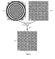
- the security pattern as illustrated in the figure 1 is based on a circularly symmetric grating (1003) obtained by sweeping a self-similar, one-dimensional signal (1001-1002) along a 360-degree circular arc.
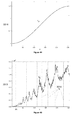
- the property of circular symmetry guarantees that the signal observed along a straight line crossing the grating at its center remains the same for all angles of the line.
- the self-similarity of the swept one-dimensional signal guarantees that the grating remains constant through changes of scale.
- An integral transform is an operator that takes a function f as its input and outputs another function T f :
- the selected integral transform is the Fourier transform
- the discrete Fourier transform (noted F hereafter) and its inverse (noted F -1 hereafter) are needed to generate a security pattern S.
- the generation of S starts in the frequency domain and is based on two components: the first one is a magnitude component R and the second one is a phase component P.
- the result of the inverse discrete Fourier transform of C is defined in the spatial domain and yields the security pattern S.
- Several methods for producing a security pattern S are derived from the general scheme that consists in applying an inverse integral transform to a pair of components ⁇ R,P ⁇ defined in the frequency domain.
- the first three methods have in common a magnitude component R taking the form of a 2D function invariant under rotation and scaling.
- the phase component P is entirely random.
- an octant with random values is symmetrically replicated in order to generate a phase component with 90°/45° axial symmetries.
- a right triangle with random values is symmetrically replicated in order to generate a phase component with 120° axial symmetries.
- the fourth method extracts the magnitude and the phase components ⁇ R 0 ,P 0 ⁇ from the discrete Fourier transform of a source halftone pattern; P 0 is used as a phase component for S, and R 0 is combined with a 2D function that is invariant under rotation and scaling in order to generate the magnitude component of S.
- the fifth method applies a pre-processing step to the magnitude component R before it is used to produce the array C: R is multiplied along its radius with a modulating function in order to fit its envelope to specific requirements.
- the envelope modulation step the power spectral density of the security pattern S becomes adjustable, allowing the generation of various colors of noise such as pink (1/f) noise, red (1/f 2 ) noise, blue noise, etc.
- the magnitude component R (1004) takes the form of a 2D circularly symmetric grating.
- the coefficients of the phase component P (1005) are produced with a stochastic process following an uniform distribution in the range [ ⁇ ,- ⁇ ]. This stochastic process may be implemented by a quantum random number generator (e.g. http://www.randomnumbers.info/) or by a pseudo-random number generator.
- C is made symmetrical by replacing its right half by a copy of its left half, rotated by 180°.
- the inverse discrete Fourier transform is applied to C in order to obtain a security pattern S (1007) in the spatial domain.
- the magnitude component R takes the form of a 2D circularly symmetric grating.
- An empty version of the phase component P is created as a 2D array of zeroes.
- P is then subdivided along its 90° and 45° axes of symmetry: the first subdivision step divides P in four quadrants along its two orthogonal axes of symmetry, and the second step further subdivides these quadrants in eight octants along the diagonal axes of symmetry of P (1008).
- this subdivision scheme is equivalent to the wallpaper group p4m; for reference, see:
- the coefficients of the bottom left-octant P 0 8 resulting from the last subdivision step are assigned random values using a stochastic process following an uniform distribution in the range [ ⁇ ,- ⁇ ]. After this first assignment, half of the values of the bottom-left quadrant P 0 4 are also determined. P 0 8 is then replicated across the diagonal axis that forms its left side in order to assign the values of the left-bottom octant P 1 8 (1009). After this second assignment, all the values of the bottom-left quadrant P 0 4 are determined, and P 0 4 is replicated across the horizontal axis that forms its upper side in order to assign the values of the top-left quadrant P 1 4 (1010).
- P contains four axes of symmetry, and these axes are preserved by the inverse Fourier transform. Apart from these symmetries however, the spatial content of S does not match the spatial content of P.
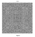
- the subdivision process may be iterated on each quadrant of P, then of each subquadrant of the quadrants, and so on (1014), as illustrated in the figure 5 .
- the dominant spatial frequency of the resulting pattern is inversely proportional to the short-range correlation of the phase component.
- the lower limit to the iterative symmetrical subdivision of the phase component depends on the visual characteristics that are expected from the security pattern.
- the depth of the basic 90°/45° subdivision is equal to one and the size of the base element (i.e. the octant P 0 8 ) is equal to p 2 , where p is the size of the phase component P. More generally, a subdivision depth of d yields a base element with a size that is equal to p 2 d . As d increases, many variants may be applied to the basic 90°/45° subdivision process used by the second method. For instance, the values of every other base quadrant may be inverted or shifted by ⁇ 4 , or two independent base quadrants may be used in alternation, and so on.
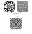
- the magnitude component R takes the form of a 2D circularly symmetric grating.
- An empty version of the phase component P is created as a 2D array of zeroes.
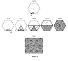
- the largest hexagon H that can be inscribed in the phase component P is then subdivided along its 120° axes of symmetry: the first subdivision step divides H in six equilateral triangles along its three longest diagonals.
- the second step subdivides each equilateral triangles in six right triangles along their three medians (1015).
- this subdivision scheme is equivalent to the wallpaper group p6m; for reference, see:
- the coefficients of the bottom-left right triangle H 0 8 resulting from the last subdivision step are assigned random values using a stochastic process following an uniform distribution in the range [ ⁇ ,- ⁇ ] (1016). After this first assignment, half the values of the bottom isosceles triangle H 0 4 are also determined. H 0 8 is then replicated across the vertical axis that forms its right side in order to assign the values of the bottom-right right triangle H 1 8 (1017). After this second assignment, all the values of the bottom isosceles triangle H 0 4 are determined.
- H 0 4 is then replicated across the 30° and 150° axes that form its left and right sides in order to assign the values of the two isosceles triangles H 1 4 and H 2 4 (1018). After this third assignment, all the values of the bottom equilateral triangle H 0 2 are determined. H 0 2 is then replicated across the 60° and 120° axes that form its left and right sides in order to assign the values of the two equilateral triangles H 1 2 and H 2 2 (1019). After this fourth assignment, H 0 2 , H 1 2 and H 2 2 are replicated across the horizontal axis passing through the center of H in order to assign the values of the three equilateral triangles H 3 2 , H 4 2 and H 5 2 that form the top half of H.
- H is replicated by a series of translations so as to fill the unassigned regions of P (1021).
- the inverse discrete Fourier transform is applied to C, as illustrated in the figure 7 , in order to obtain a security pattern S in the spatial domain (1022).
- P contains six axes of symmetry.
- P is implicitly sampled on a hexagonal grid. Since C is based on P, the same consequence applies; therefore, if the coefficients of C are directly mapped onto the orthogonal grid used by the inverse Fourier transform, the axes of symmetry in P will not be completely preserved in S (1023), as illustrated in the figure 8 .
- the coefficients of P and R must be resampled on an orthogonal grid before they are combined to form the coefficients of C. This resampling has the side effect of changing the aspect ratio of P (1024), as illustrated in the figure 9 .
- the discrete Fourier transform is applied to a source halftone pattern having the same dimensions as R in order to generate an array C 0 of complex numbers.
- a magnitude component R 1 having the same size as the largest dimension of R 0 is synthesized under the form of a 2D circularly symmetric grating, and is then resized along one direction only so as to have exactly the same size as R 0 (1027). Since R 0 is not necessarily square, this non-uniform resizing can have the effect of distorting the concentric rings that form the 2D circularly symmetric grating into concentric ellipses.
- Examples of the function M used for mixing R 0 and R 1 include linear combinations of R 0 with R 1 , weighted multiplications of R 0 with R 1 , or combinations of these two operations.
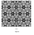
- the inverse discrete Fourier transform is applied to C in order to obtain a security pattern S in the spatial domain (1029), as illustrated in the figure 12 .
- S is not necessarily square; however, the magnitude component of the discrete Fourier transform of any square region (1030) of S yields the original 2D circularly symmetric grating (1031), as illustrated in the figure 13 .
- the Fourier transform of the security pattern S generated with one of the four previous methods has a magnitude component that is essentially flat. Because of this flatness, higher spatial frequencies prevail over lower spatial frequencies in S, which offers a visual aspect close to white noise.
- E is maximal at the center of R and decreases monotonically toward the borders of R.
- R with E (1054-1061) has the effect of modulating the power spectral density of S in the frequency domain, as illustrated in the figures 15 and 16 .
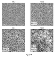
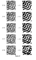
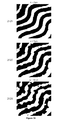
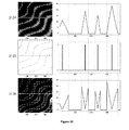
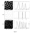
- this modulation is reflected on the coarseness of the security pattern, which can be continuously changed from fine to coarse in order to meet specific perceptual requirements, either in grayscale from (1062-1065), as illustrated in the figure 17 , or in bilevel form (1066-1069), as illustrated in the figure 18 .
- the set of possible values for the dots of a halftone image contains two values: 0 and 1, also called ON and OFF.
- a dot with a value of 0 (ON) indicates the presence of ink at the position it occupies, and is represented by a black pixel.
- a dot with a value of 1 (OFF) indicates the absence of ink at the position it occupies, and is represented by a white pixel.
- a separation image is defined as an image crafted by the designer of the banknote with the purpose of producing one of the offset or intaglio plates that are used for transferring the ink colors to the banknote paper during the printing process.
- a separation image takes the form of a bilevel halftone image; the black areas indicate the presence of ink, and the white areas indicate the absence of ink.
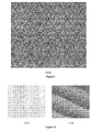
- One additional method is also provided, which takes a continuous tone, grayscale image (2052) as its input, as illustrated in the figure 21 , and produces a security grayscale image (2053) as its output, as illustrated in the figure 22 . This security grayscale image can then be used as the input of a standard halftoning process in order to generate a security separation halftone image.
- the security pattern is merged with a low-resolution grayscale image that is subsequently halftoned in order to produce a high-resolution halftone image.
- the security pattern is merged with a high-resolution halftone image.
- the security pattern is merged with a high-resolution halftone image, and the features of the halftone image are preserved against excessive distortions caused by erosion and dilation.
- the security pattern is merged with a high-resolution halftone image, and the features of the halftone image having a size inferior to a predetermined threshold are preserved.
- a security halftone image M used as a separation for printing one layer of ink on a banknote is obtained by modulating an original grayscale image G (2052) with a security pattern S in order to obtain a security grayscale image G' (2053).
- the security grayscale image G' is then halftoned to produce a bilevel security halftone image M.
- the resolution of the grayscale image G doesn't have to match the printing resolution of M, and low-resolution (e.g. 300 dpi) grayscale images are commonly used to produce halftone images with a resolution ten times higher.
- the interpolation factor j is in the range [0..1] and controls the amount of the security pattern S that is merged with the grayscale image G.
- the security grayscale image G' is close to G and the visibility of the security pattern S is low; conversely, when j gets closer to 1, the security grayscale image G' gets closer to S and the structure of the security pattern becomes more and more visible.
- the interpolation factor j plays the role of an embedding intensity factor and will be referred to as such hereafter.
- the security grayscale image G' is halftoned in order to generate a bilevel security separation halftone image M.
- Possible halftoning methods include cluster-dot screening, error diffusion, blue- and green-noise mask dithering, artistic screening; basically any halftoning method can be used as long as it preserves the spatial frequencies of G'.
- a security halftone image M (2051) used as a separation for printing one layer of ink on a banknote is generated by modulating an original separation halftone image H (2050) with a security pattern S.
- the modulation involves the generation of an auxiliary grayscale image H' derived from the halftone image H.
- the security pattern S is interpolated with the auxiliary image H', and the result of the interpolation is thresholded in order to produce a bilevel security halftone image M.
- a pair of complementary distance maps ⁇ dH K , dH w ⁇ is derived from the halftone image H.
- Each distance map is a two-dimensional array of positive numbers. Each array has the same width and height as the halftone image H.
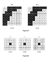
- the first map dH K illustrated in the figure 23 is called a distance-to-black map (2101) and measures the distance of every white pixel of H to the nearest black pixel of H. By convention, the distance-to-black of a black pixel is zero.
- the second map dH W illustrated in the figure 23 is called a distance-to-white map (2102) and measures the distance of every black pixel of H to the nearest white pixel of H. By convention, the distance-to-white of a white pixel is zero.
- the distance function used in the pair of distance maps ⁇ dH K , dH W ⁇ can take three different forms.
- the second form illustrated in the figure 24 is called the Chebyshev distance, also known as the chessboard distance, and the L ⁇ distance (2104).
- the third form illustrated in the figure 24 is called the Euclidean distance, also known as the L 2 distance (2105).
- the distance maps dH K and dH W preserve the topology of the white (resp. black) areas of the halftone image H.
- dH K and dH W are clamped so that their elements are in the range [0..127], then they are merged together in order to build the auxiliary grayscale image H'.
- the figure 25 illustrates the construction of the auxiliary grayscale image H'.
- a small halftone image H (2106) is sampled along a horizontal line; by convention, the black pixels have a value of 0 and the white pixels have a value of 1.
- the distance-to-black map dH K (2107) derived from H is sampled along the same horizontal line; the pixels of dH K that correspond to a white pixel in H have a value indicating their L 1 distance to the nearest black pixel of H, and the pixels of dH K that correspond to a black pixel in H are uniformly equal to zero.
- the distance-to-white map dH W (2108) derived from H is also sampled along the same horizontal line; the pixels of dH W that correspond to a black pixel in H have a value indicating their L 1 distance to the nearest white pixel of H, and the pixels of dH W that correspond to a white pixel in H are uniformly equal to zero.
- the auxiliary grayscale image H' (2109) is also sampled along the same horizontal line; the pixels of H' that correspond to a white pixel in H have a positive value, and the pixels of H' that correspond to a black pixel in H have a negative value.
- the interpolation factor j is in the range [0..1] and controls the amount of the security pattern S that is merged with the grayscale image H', as illustrated in the figure 27 .
- the interpolation factor j plays the role of an embedding intensity factor (2114-2118) and will be referred to as such hereafter.
- the fourth step of the method produces the bilevel security halftone separation image M (2112) by thresholding the merged grayscale image M' (2111). All the pixels of M' with a value below 127.5 are mapped to the value 0 and produce a black pixel in M; all the pixels with a value equal to or above 127.5 are mapped to the value 1 and produce a white pixel in M.
- the security pattern S is balanced, that is if its average value is close to 0, then the black percentage of an arbitrary area A of M will be close to the black percentage of the same area A in H.
- using a balanced security pattern is a sufficient condition for ensuring that the final halftone image M is close, on average, to the original halftone image H, regardless of the embedding intensity factor j.
- an auxiliary grayscale image H' based on the distance-to-black and distance-to-white maps of an original halftone image H is generated by the steps 1 and 2 of the second method.
- H' is merged with the security pattern S.
- the pixels of H' having an absolute value inferior or equal to a value ⁇ are linearly interpolated between S and H'.
- the pixels of H' having an absolute value superior to ⁇ are not interpolated, but their value is copied directly from H.
- the fourth step of the third method is identical to the fourth step of the second method: the merged grayscale image M' is thresholded at the level 0 in order to produce a bilevel image.
- the value ⁇ acts as a limiter for erosion and dilation of the halftone elements (2119), as illustrated in the figure 28 : the parts of a halftone element that are within a distance ⁇ of the border are eroded or dilated normally, but the parts that are beyond this distance are left untouched (2120).
- This limited merging illustrated in the figure 29 has the effect of reducing the distortion brought by the security pattern in the security halftone image M (2121-2123).
- the ⁇ limiter is defined by the designer of the banknote in accordance to the characteristics of the original halftone image H and the specifications of the target printing press. For instance, let's suppose that the printing press has a minimum dot size of 30 ⁇ m.
- a pair of complementary distance maps ⁇ dH K , dH W ⁇ is derived from an original halftone image H and is merged together in order to generate an auxiliary grayscale image H' following the steps 1 and 2 of the second method.
- the ridges that form their medial axis are computed and stored in a pair of bilevel images forming the ridge map R W (2125) and R K (2128), with 0 (black) indicating a ridge pixel in the corresponding distance map, and 1 (white) indicating a pixel that does not belong to any ridge.
- a ridge pixel There are many ways of defining a ridge pixel, as described in http://en.wikipedia.org/wiki/Ridge detection.
- a simple but efficient definition is to consider that a pixel belongs to a ridge if its value is superior or equal to the value of at least 6 of its 8 neighbors.
- ridges are lines with a width of exactly one or two pixels.
- R W the ridges are located exactly halfway between the screen elements that constitute the original halftone image H.
- R K the ridges are located exactly on the medial axis of the screen elements that constitute the original halftone image H.
- the distance-to-black maps ⁇ T W , T K ⁇ of the ridges R W and R K are then computed.
- the pixels of T W (2126) that correspond to a black pixel in H are then set to zero, and the pixels of T K (2129) that correspond to a white pixel in H are also set to zero.
- T W and T K are referred to hereafter as "thickness maps”. More specifically, T W measures the thickness of the white space between screen elements, and is therefore called “thickness-of-white”, and T K measures the thickness of the screen elements themselves, and is therefore called “thickness-of-black”.
- These thickness maps are used in the third step of the fourth method, which merges H' with the security pattern S in order to obtain a security grayscale image M'.
- the pixels of H' that correspond to a black pixel of H are matched coordinate-wise with the pixels of the thickness-of-black map T K . If a black pixel is associated with a thickness T K superior or equal to a threshold ⁇ K , then this pixel is linearly interpolated between S and H'. If a black pixel is associated with a thickness T K inferior to the threshold ⁇ K , its value is copied directly from H.
- a similar decision is applied to the pixels of H' that correspond to a white pixel of H: they are matched coordinate-wise with the pixels of the thickness-of-white map T W .
- a white pixels is associated with a thickness T W superior or equal to a threshold ⁇ W , then this pixel is linearly interpolated between S and H'. If a white pixel is associated with a thickness T W inferior to the threshold ⁇ W , its value is copied directly from H.
- the fourth step of the fourth method is identical to the fourth step of the first and second methods: the merged grayscale image M' is thresholded at the level 0 in order to produce a bilevel image.
- the value ⁇ W acts as a limiter for the dilation of the halftone elements (2130), as illustrated in the figure 32 : a halftone element may be dilated up to the point where it would reduce the thickness of its neighboring white space below ⁇ W (2131).
- the value ⁇ K acts as a limiter for the erosion of the halftone elements (2130): a halftone element may be eroded up to the point where this erosion would bring its thickness below ⁇ K (2131).
- the ⁇ K and ⁇ W limiters guarantee, that a minimum thickness will be preserved in the black and white screen elements.
- This limited merging illustrated in the figure 33 has the effect of reducing the distortion brought by the security pattern in the security halftone image M (2132-2134).
- the ⁇ K and ⁇ W limiters used in the third step are defined by the designer of the banknote in accordance to the characteristics of the halftone image H and the specifications of the target printing press. For instance, let's suppose that the printing press has a minimum dot size of 30 ⁇ m and a minimum dot interval of 40 ⁇ m. Let's also suppose that the designer wants to use this press for printing a halftone consisting of alternating black and white lines, with each line having a minimum thickness of 50 ⁇ m.
- the ⁇ K limiter should be set at 30 ⁇ m in order to force black lines to have a thickness of at least 30 ⁇ m, and that the ⁇ W limiter should be set at 40 ⁇ m in order to force white lines to have a thickness of at least 40 ⁇ m.
- the pattern embedded in a security image is typically recovered after the printout of the image.
- a digital imaging device like a digital scanner or a camera for instance
- the pattern is designed in such a way that it is possible to trigger a primary detection with a mono-dimensional signal processing performed along a straight line having an arbitrary direction across the pattern, for any scale and rotation transformations (in a previously defined range). If this primary detection yields a conclusive answer, then the detection can stop with a positive or negative result. However, if the answer of the primary detection is inconclusive, a secondary detection process is launched and performs a more thorough examination of the image.
- the reliability of the detection trigger false-positive and false-negative detections
- the robustness to geometrical transforms the robustness to loss of data in the security image.
- the reliability of the detection basically relies on a statistical test. This test must be performed on a sufficiently large set of data in order to reach the performance desired for false-positive (signal detected while not being present) and for false-negative (signal not detected while being present). In the targeted application, the false-positive rate is expected to reach 1 over 10 millions or better.
- the statistical data can be processed during the digitization or during an unauthorized printing attempt. Since the detection approach relies on a 1 dimensional signal processing, it may also be performed in real-time as data is streamed into the hardware into which the detection is performed. It is also possible to make this primary detection more tolerant to false positives and use a secondary, more thorough detection process on the cases that trigger a positive, yet inconclusive answer.
- the robustness to geometrical transforms is achieved by using a source 1D signal that is invariant under affine transformations.
- the robustness to loss of data in the security image is achieved by using a secondary, more systematic detection process when the primary detection process returns an inconclusive answer.
- the primary detection process of the embedded security pattern is based on the discrete Fourier transform of a projection of the image and is described in WO/2006/048368 .
- Such cases include debased security images where the security pattern covers only a small fraction of the total area, images with a very low resolution or security images that were compressed with a lossy compression algorithm using a low quality factor.
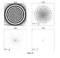
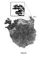
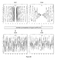
- FIG 34 An example of such a debased security image is illustrated in the figure 34 (3001) with a low-resolution security pattern (3002) that covers only 1/4 th of the image area, the remaining 3/4 th being a uniform gray (3003).
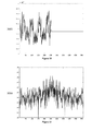
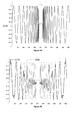
- the magnitude (3004) of the discrete 2D Fourier transform of (3001) is illustrated in the figure 35 by a faint 2D circularly symmetric grating; a closer look on figure 35 reveals that a lot of noise is present in this 2D circularly symmetric grating. As illustrated in the figure 36 and 37 , this noise has a large impact on the magnitude (3006) of the discrete 1D transform of the projection (3005) of the image (3001) along its columns, obtained by the application of the projection-slice theorem.
- a secondary detection process is carried out in order to obtain an answer with a sufficient degree of reliability.
- This secondary process consists of 12 steps comprising 11 preprocessing steps followed by 1 comparison step; these steps are described in the paragraphs below numbered from step 1 to step 12.
- a printed banknote is the result of an industrial process, and as such it must undergo stringent quality controls before its release. If it is supposed to contain an embedded security pattern, the actual presence and the quality of this pattern must be assessed in order to get a reliable evaluation of the response that it will trigger when going through a signal detector.
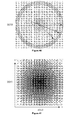
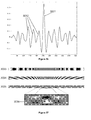
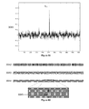
- This assessment is performed on a digital copy of the banknote, usually acquired through a scanning device. As illustrated in the figure 62 , the digital copy (4101) is subdivided into blocks of identical size that are sampled at regularly spaced intervals. If a quick assessment is desired, the sampling can be loose (4102) and there is little or no overlapping between two successive blocks. On the other hand, if a thorough assessment is desired, the sampling must be tight (4103) and there is a lot of overlapping between two successive blocks.
- Each block is subjected to a secondary detection process.
- the magnitude of highest cross-correlation peak X k obtained for a given block in step 12 of the secondary detection process is associated with the coordinates ⁇ x, y ⁇ of the center of that block.
- the set of triples ⁇ x, y, X k ⁇ constitutes a map of the strength of the signal across the banknote (4104-4105), as illustrated in the figure 63 . This map serves as a basis for a visual assessment of the quality of the banknote with respect to the signal strength. If the assessment must be automatized, several estimators may be used for deriving a single quality factor, such as the maximal signal strength over all the map, the average strength across the map, the amount of map points with a strength superior to a predefined threshold, etc.
Abstract
- determining a distance map of the original bi-level image,
- generating a merged image by linearly interpolating at least a part of said distance map with said security pattern,
- thresholding the merged image to obtain the security bi-level image,
- applying the security bi-level image on a support.
Description
- The present invention concerns the field of the methods to embed security patterns within a printed image, in particular for banknotes.
- Many solutions have been devised in the past in order to allow the easy spotting of counterfeit documents. Recently, more direct approaches were proposed that try to stop the counterfeiting attempt before a counterfeit document can be actually produced. In these approaches, the document carries a security feature that is detectable by the device used for the counterfeiting attempt. When detecting the security feature, the device can react so as to thwart the attempt by interrupting its normal operation, shutting itself down or silently distorting its output. Existing solutions are based on optically visible features, or on invisible elements using special consumables, or on digital signal processing methods. Visible solutions that do not require special consumables such as security inks offer a weak resistance against the ingenuity of counterfeiters. On the other hand, the detectors of invisible features have high demands for computational power and memory. It should be noted that in both cases feature detection is usually based on the acquisition of a digital image followed by a signal processing method for digitally detecting the security feature. As a consequence, a detector for an invisible solution cannot be implemented directly into those devices with low computational capabilities, like printers, scanners, monitors or digital cameras, that are frequently involved in counterfeiting attempts, but it must be instead implemented in software at the computer level. The current invention describes a way to eschew this limitation by using a special combination of a security pattern and a detection process, allowing for visible or invisible features that can be detected with little processing power. Since it is designed to protect banknotes that are usually entirely covered by a rich graphical content, the security pattern may be seamlessly integrated into the separation halftone images that are crafted by the designer of the banknote, and that serve the purpose of producing the offset or intaglio plates used for transferring the inks to the banknote paper during the printing process. If required, the integration of the security pattern can be adapted for preserving critical characteristics of these separation halftone images: for instance, the device performing the integration can be instructed to preserve a minimal thickness in the modulated halftone elements, or the amplitude of modulation can be limited to a set of predefined values. In addition, the coarseness and the internal symmetries of the security pattern may be freely adjusted by the designer so as to blend smoothly and harmoniously in the banknote design.
- Several techniques used for protecting valuable documents against illegal duplication use small, localized variations of the visual appearance of the protected documents. These variations can take the form of a human-readable pattern (microtext, evolutionary screen dots [
US 6,198,545 ], moiré patterns [US 5,995,638 ], microstructure color differences [EP 1073257A1 ]), or they can be implemented using invisible, but machine-readable patterns (CryptoglyphWO01/00560 WO03/04178 - This requirement poses two problems. A first problem arises with the authentication of a document in the case where a minimum document surface is not available in its entirety at some time during the authentication process. This is for instance the case for documents that are digitally transmitted over a serial line or a bus system, e.g. document transmission from a scanner to a computer, from a camera to a computer, from a computer to a printer, between two computers or between a computer and a mobile phone.
- A second problem arises when the authentication of documents has to be performed by devices that have only little memory or a low processing power. When the size of the document increases linearly, the memory and time required to process the document increase geometrically. Therefore, authenticating security documents used in everyday life, e.g. banknotes, plane tickets or ID cards, is a major problem for devices such as scanners, printers, digital cameras and mobile phones.
- One important approach for invisible signal embedding is referred in the literature as "digital watermarking". Digimarc describes several approaches especially suitable for banknotes in patents
US6771796 ,US6754377 ,US6567534 ,US6449377 . These approaches rely on modifications performed at a microscopic level (i.e. 40 µm or lower, corresponding to about 600 dpi resolution). These modifications are done in such a way that they can be detected at a macroscopic level (i.e. using 100 dpi scanning resolution), but are generally invisible for the naked eye (Digimarc also describes some techniques yielding to visible alterations inUS6674886 andUS6345104 ). The detection of the digital watermark and decoding of the embedded data are performed using combinations of image processing algorithms which can be found in the digital watermarking literature. Some of these algorithms include in particular reference patterns in Fourier domain (for affine transform registration), cross-correlation in the spatial domain (for registration against image shift) and correlation in order to decode the signal. It should be highlighted that the most challenging part of the detection process is usually to define a process that is robust against geometrical transformations as well as reaching satisfying reliability performance. In some cases, a so-called "fragile digital watermarking" technique is used. With this technique, the embedded signal disappears when a copy of the protected document is performed. It enables to distinguish between original documents and copies. One example of such an approach is described inWO2004/051917 . Other approaches enable data embedding in halftone images. Many solutions rely on an optical, analog process for revealing the data. However, some solutions are also based on digital processing. In this case the common technique is to modify slightly the threshold matrix in order to embed some information. Basically, any halftone image produced using this matrix and the original gray level image carries the signal. One solution is described inUS 6,760,464 (andUS6,694,041 ) and another approach is also presented inUS6,723,121 each with a different watermarking technique. A more generic approach which does not specify a particular digital watermarking technique is described inUS6,775,394 . Some approaches do not use digital watermarking technique (in the sense of robust steganography), like in patentUS6,839,450 where authors describe a detection method of data embedded in halftone images using matched filter. It is possible to significantly improve embedding performance in halftone images by using a modified version of more sophisticated halftoning schemes. For instance,US2003021437 gives a description of a generation of a dither matrix produced from a bilevel image using morphological operations. This dither matrix is then used for producing halftone images, which may be used in security printing. Inserting a signal into a digital media or printing it on a document and detecting it later has been address extensively in older patents. From a technical point of view the main issues to solve are signal design, signal embedding and signal detection. Here, the signal can be a modification applied to an existing image, or it can be embodied by the generation of an independent signal printed over an existing document or overlaid onto a digital image. The signal design is largely driven by the functional behavior of the detector. It is desirable that the detector should be able to detect or to retrieve the embedded signal independently of possible geometrical transformations applied to the protected media. To solve this challenge it is state of the art in digital marking technologies to either embed additional key characteristics in the spatial or even frequency domain that later allow for the identification of the geometrical transformation and its inversion (for instance the patentUS6,408,082 ,US6,704,869 andUS6,424,725 describe approaches where a log-polar in the transform domain is used to compute the geometrical transform). A different approach is based on the design and embedding of an auto-similar signal. During detection an auto-correlation function is computed. The analysis of the auto-correlation function then allows for the identification of the geometrical transformations and their inversions. - All the above solutions solve the problem of robust detection using 2-dimensional processing techniques for continuous or halftone images. However, none of them perform this detection using a 1D signal processing, which is required for applications based on low computing power systems.
- A 1D solution is described in
AU 2002951815 - Another 1D solution is described in
WO/2006/048368 where the inventors describe the generation of a security pattern under the form of a 2D grating obtained by sweeping a 1D signal along a predefined curve. The security pattern may be visible in either the spatial domain or in the frequency domain. It may be added to the banknote as a printed overlay, or it may be used as a dither matrix in order to generate a halftone image printed on the banknote. However, the invention described inWO/2006/048368 does not offer the possibility of controlling the visual aspect of the security pattern. In addition, it does not provide a method for modulating an existing halftone image with the security pattern. Finally, the preservation of essential characteristics of the halftone elements that are merged with the pattern cannot be guaranteed. - The present invention proposes a method for generating a security bi-level image used to form one of the inks of a banknote, said image comprising an original bi-level image and a security pattern, said security pattern being obtained in the spatial domain by the inverse Fourier transform of the combination in the frequency domain between the Fourier transform of an auxiliary image and a two-dimensional sweep, said two-dimensional sweep being a circularly symmetric, two-dimensional pattern created by sweeping a self-similar, one-dimensional function along a 360-degree arc, such as said security pattern being detectable from the maximum value of the cross-correlation of said one-dimensional function with the Fourier transform of one line of said banknote, said method comprising the step of :
- determining a distance map of the original bi-level image,
- generating a merged image by linearly interpolating at least a part of said distance map with said security pattern,
- thresholding the merged image to obtain the security bi-level image,
- applying the security bi-level image on a support.
- The present invention discloses methods for generating a circularly invariant 2D grating based on a self-similar 1D source signal, for assembling a security pattern in the frequency domain based on a 2D grating and a random phase, for deriving a phase with orthogonal or hexagonal symmetries from a random phase, and for modulating the coarseness of a security pattern in the frequency domain. The present invention also discloses methods for embedding a security pattern into an existing grayscale image, for generating a grayscale image that follows the morphology of an existing bilevel image, for generating a thickness map of a halftone image, and for merging a security pattern with a halftone image while preserving essential morphological characteristics of the halftone elements.
- In addition, the present invention discloses methods for retrieving a 1D signal from a 2D image by performing a circular sweep on the discrete Fourier transform of the 2D image, for resampling and flattening a 1D signal, for applying a predefined random permutation to a 1D signal and for cross-correlating a permuted 1D signal with a codebook of permuted templates.
- Finally, the present invention discloses a method for measuring the overall signal strength as well as the local signal strength in a banknote that contains some areas embedded with a security pattern.
- The disclosed invention is easier to understand with the help of the enclosed figures, in which:
-
Figure 1 shows the generation of a circularly symmetric 2D signal by sweeping a 1D signal along a circle. -
Figure 2 shows a circularly symmetric 2D signal used as a magnitude component (R), a random pattern used as a phase component (P), and the combination of these two components in the frequency domain followed by an inverse Fourier transform that produces a security pattern in the spatial domain (S). -
Figure 3 shows the generation of a phase component with 90°/45° symmetry. -
Figure 4 shows the generation of a security pattern (S) in the frequency domain from a circularly symmetric magnitude component (R) and a phase component (P) with 90°/45° symmetry. -
Figure 5 shows a phase component with recursive 90°/45° symmetry. -
Figure 6 shows the generation of a phase component with 120°/60° symmetry. -
Figure 7 shows the generation of a security pattern (S) in the frequency domain from a circularly symmetric magnitude component (R) and a phase component (P) with 120°/60° symmetry. -
Figure 8 shows a phase component with 120°/60° symmetry that is sampled on an orthogonal grid. -
Figure 9 shows a phase component with 120°/60° symmetry that is sampled on a hexagonal grid. -
Figure 10 shows the magnitude and the phase of a pattern with 120°/60° symmetry that is sampled on an hexagonal grid. -
Figure 11 shows the mixing of two magnitude components. -
Figure 12 shows a security pattern with 120°/60° symmetry. -
Figure 13 shows the magnitude component of the 2D Fourier transform of a square chunk of a security pattern with 120°/60° symmetry. -
Figure 14 shows 1D slices of four different 2D envelope modulation functions. -
Figure 15 shows 1D slices of a 2D circularly symmetric grating multiplied by four different 2D envelope modulation functions. -
Figure 16 shows a 2D circularly symmetric grating multiplied by four different 2D envelope modulation functions. -
Figure 17 shows a grayscale security pattern generated with four different granularities. -
Figure 18 shows a bilevel security pattern generated with four different granularities. -
Figure 19 shows an original halftone separation image. -
Figure 20 shows a security halftone separation image. -
Figure 21 shows an original grayscale image. -
Figure 22 shows a security grayscale image. -
Figure 23 shows a fragment of a distance-to-black map and a fragment of a distance-to-white map. -
Figure 24 shows the fragments of a L1, a L∞ and a L2 distance map. -
Figure 25 shows a bilevel image, its distance-to-black and distance-to-white maps, and the auxiliary grayscale image based on these two maps. -
Figure 26 shows an auxiliary grayscale image, a grayscale security pattern, the merging of the image and the security pattern, and the bilevel image obtained by thresholding this merging. -
Figure 27 shows on the left a grayscale security pattern merged with an auxiliary grayscale image at five different embedding intensity levels, and on the right the bilevel images obtained by thresholding the result of the mergings. -
Figure 28 shows a bilevel image with erosion and dilation limiters, and a second bilevel image obtained by embedding a security pattern in the first, constrained by these erosion and dilation limiters. -
Figure 29 shows three bilevel images embedded with a security pattern, constrained by three different erosion and dilation limits. -
Figure 30 shows a distance-to-black map, its ridge map and the thickness-of-white map built on this ridge map. -
Figure 31 shows a distance-to-white map, its ridge map and the thickness-of-black map built on this ridge map. -
Figure 32 shows a bilevel image with black and white thickness limiters, and a second bilevel image obtained by embedding a security pattern in the first, constrained by these thickness limiters. -
Figure 33 shows three bilevel images embedded with a security pattern, constrained by three different thickness limiters. -
Figure 34 shows a debased security image consisting in a fragment of a downsampled security pattern surrounded by a uniform gray. -
Figure 35 shows the magnitude component of the 2D Fourier transform of a debased security image. -
Figure 36 shows the projection of a debased security image. -
Figure 37 shows the magnitude of the 1D Fourier transform of the projection of a debased security image. -
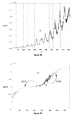
Figure 38 shows a source 1D function. -
Figure 39 shows the cross-correlation of a source 1D function with the magnitude of the 1D Fourier transform of the projection of a debased security image. -
Figure 40 shows the magnitude component of a 2D Fourier transform superimposed with the polar coordinate system that is used to rank the coefficients of this magnitude component according to their radius. -
Figure 41 shows a 2D table of precalculated radii. -
Figure 42 shows a ragged array containing the coefficients of the magnitude component of a 2D Fourier transform, said coefficients being ranked according to their radius. -
Figure 43 shows the order statistic of the coefficients of the magnitude component of a 2D Fourier transform, said coefficients being ranked according to their radius. -
Figure 44 shows the radial magnitude component of the 2D Fourier transform of the discrete approximation to a Laplacian filter. -
Figure 45 shows the product of an order statistic with a Laplacian filter, over an inverse-log grid. -
Figure 46 shows a filtered order statistic resampled over an inverse-log grid. -
Figure 47 shows the left and right extension of a resampled, filtered order statistic. -
Figure 48 shows an extended signal and its moving window average. -
Figure 49 shows an extended signal after a low-pass filtering. -
Figure 50 shows an extended signal after a low-pass and a high-pass filtering. -
Figure 51 shows the middle third of a flat, extended signal over a log grid. -
Figure 52 shows the middle third of a flat, extended signal after a log-resampling. -
Figure 53 shows the signature of an image chunk under the form of a normalized, filtered signal concatenated with a copy of itself obtained by a symmetry around the vertical axis. -
Figure 54 shows a member of a codebook of template functions. -
Figure 55 shows the superposition of the signature of an image chunk and a matching template function. -
Figure 56 shows the 1D cross-correlation of a template function with a signature. -
Figure 57 shows a signature, a set of template functions and the cross-correlations of the signature with each template of this set, stacked up so as to form a grayscale image. -
Figure 58 shows a template and a signature that are decorrelated by a permutation of their coefficients. -
Figure 59 shows the 1D cross-correlation of a decorrelated template function with a decorrelated signature. -
Figure 60 shows a decorrelated signature, a set of decorrelated template functions and the cross-correlations of the signature with each template of this set, stacked up so as to form a grayscale image. -
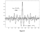
Figure 61 shows the superposition of two cross-correlations. -
Figure 62 shows a digital copy of a banknote, a subdivision of a digital copy in regularly spaced, non-overlapping blocks, and a subdivision of a digital copy in regularly spaced, overlapping blocks. -
Figure 63 shows two maps of the strength of the signal across a digital copy of a banknote, the first one with a loose sampling rate and the second one with a tight sampling rate. - The security pattern as illustrated in the
figure 1 is based on a circularly symmetric grating (1003) obtained by sweeping a self-similar, one-dimensional signal (1001-1002) along a 360-degree circular arc. The property of circular symmetry guarantees that the signal observed along a straight line crossing the grating at its center remains the same for all angles of the line. The self-similarity of the swept one-dimensional signal guarantees that the grating remains constant through changes of scale. - The methods exposed hereafter for embedding a circularly symmetric grating are all based on an integral transform and its inverse. An integral transform is an operator that takes a function f as its input and outputs another function Tf:

where the function K(t,u) is the kernel of the transform. If K(t,u) has an associated inverse kernel K-1(u,t), then the inverse integral transform is defined as:
- The simplest example of an integral transform is the identity transform, with:

and
where δ is the Dirac distribution. - Another example is the Laplace transform, with:

and
- Yet another example commonly used in signal processing is the Fourier transform, with:

and
- When working with images made of discrete pixels, a specific form of the selected integral transform is needed. For instance, if the selected integral transform is the Fourier transform, then the discrete Fourier transform (noted F hereafter) and its inverse (noted F -1 hereafter) are needed to generate a security pattern S. The generation of S starts in the frequency domain and is based on two components: the first one is a magnitude component R and the second one is a phase component P. The magnitude and the phase components are used together to produce an array C of complex numbers using the relation Cxy = Rxy ·eiPxy, where i denotes the square root of -1. The result of the inverse discrete Fourier transform of C is defined in the spatial domain and yields the security pattern S. By construction, when the discrete Fourier transform is applied to S, it yields back the array C in the frequency domain. The magnitude component R can be retrieved from the coefficients of C by computing their absolute value: if Cxy = a + bi, then

- Several methods for producing a security pattern S are derived from the general scheme that consists in applying an inverse integral transform to a pair of components {R,P} defined in the frequency domain. The first three methods have in common a magnitude component R taking the form of a 2D function invariant under rotation and scaling. In the first method, the phase component P is entirely random. In the second method, an octant with random values is symmetrically replicated in order to generate a phase component with 90°/45° axial symmetries. In the third method, a right triangle with random values is symmetrically replicated in order to generate a phase component with 120° axial symmetries.
- The fourth method extracts the magnitude and the phase components {R0,P0} from the discrete Fourier transform of a source halftone pattern; P0 is used as a phase component for S, and R0 is combined with a 2D function that is invariant under rotation and scaling in order to generate the magnitude component of S.
- The fifth method applies a pre-processing step to the magnitude component R before it is used to produce the array C: R is multiplied along its radius with a modulating function in order to fit its envelope to specific requirements. With this envelope modulation step, the power spectral density of the security pattern S becomes adjustable, allowing the generation of various colors of noise such as pink (1/f) noise, red (1/f2) noise, blue noise, etc.
- In the first method illustrated in the
figure 2 , the magnitude component R (1004) takes the form of a 2D circularly symmetric grating. The coefficients of the phase component P (1005) are produced with a stochastic process following an uniform distribution in the range [π,-π]. This stochastic process may be implemented by a quantum random number generator (e.g. http://www.randomnumbers.info/) or by a pseudo-random number generator. R and P are then used to compute an array C (1006) of complex numbers using the relation Cxy =Rxy ·eiPxy. C is made symmetrical by replacing its right half by a copy of its left half, rotated by 180°. The inverse discrete Fourier transform is applied to C in order to obtain a security pattern S (1007) in the spatial domain. - In the second method illustrated in the
figure 3 , the magnitude component R takes the form of a 2D circularly symmetric grating. An empty version of the phase component P is created as a 2D array of zeroes. P is then subdivided along its 90° and 45° axes of symmetry: the first subdivision step divides P in four quadrants along its two orthogonal axes of symmetry, and the second step further subdivides these quadrants in eight octants along the diagonal axes of symmetry of P (1008). Formally, this subdivision scheme is equivalent to the wallpaper group p4m; for reference, see: - http://en.wikipedia.org/wiki/Wallpaper group#Group p4m
- Once the subdivision process is complete, the coefficients of the bottom left-
octant 
left quadrant 

bottom octant 
left quadrant 

quadrant 
left half 

right half 
figure 4 , in order to obtain a security pattern S in the spatial domain (1013). - By construction, P contains four axes of symmetry, and these axes are preserved by the inverse Fourier transform. Apart from these symmetries however, the spatial content of S does not match the spatial content of P.
- If P is large, the subdivision process may be iterated on each quadrant of P, then of each subquadrant of the quadrants, and so on (1014), as illustrated in the
figure 5 . However, the dominant spatial frequency of the resulting pattern is inversely proportional to the short-range correlation of the phase component. As the subdivision depth increases, so does the short-range correlation of the phase component, and the resulting security pattern tends to become less and less uniform. Therefore, the lower limit to the iterative symmetrical subdivision of the phase component depends on the visual characteristics that are expected from the security pattern. - The depth of the basic 90°/45° subdivision is equal to one and the size of the base element (i.e. the
octant 


- In the third method illustrated in
figure 6 , the magnitude component R takes the form of a 2D circularly symmetric grating. An empty version of the phase component P is created as a 2D array of zeroes. The largest hexagon H that can be inscribed in the phase component P is then subdivided along its 120° axes of symmetry: the first subdivision step divides H in six equilateral triangles along its three longest diagonals. The second step subdivides each equilateral triangles in six right triangles along their three medians (1015). Formally, this subdivision scheme is equivalent to the wallpaper group p6m; for reference, see: - http://en.wikipedia.org/wiki/Wallpaper group#Group p6m
- Once the subdivision process is complete, the coefficients of the bottom-left
right triangle 
isosceles triangle 

right triangle 
isosceles triangle 

isosceles triangles 

equilateral triangle 

equilateral triangles 


equilateral triangles 

figure 7 , in order to obtain a security pattern S in the spatial domain (1022). - By construction, P contains six axes of symmetry. However, unlike the phase component generated with the second method, P is implicitly sampled on a hexagonal grid. Since C is based on P, the same consequence applies; therefore, if the coefficients of C are directly mapped onto the orthogonal grid used by the inverse Fourier transform, the axes of symmetry in P will not be completely preserved in S (1023), as illustrated in the
figure 8 . In order to preserve the hexagonal symmetry of P in S, the coefficients of P and R must be resampled on an orthogonal grid before they are combined to form the coefficients of C. This resampling has the side effect of changing the aspect ratio of P (1024), as illustrated in thefigure 9 . - In the fourth method, the discrete Fourier transform is applied to a source halftone pattern having the same dimensions as R in order to generate an array C0 of complex numbers. The magnitude (1025) and the phase (1026) components {R0,P0} of C0 are extracted with the
relations 


figure 10 . A magnitude component R1 having the same size as the largest dimension of R0 is synthesized under the form of a 2D circularly symmetric grating, and is then resized along one direction only so as to have exactly the same size as R0 (1027). Since R0 is not necessarily square, this non-uniform resizing can have the effect of distorting the concentric rings that form the 2D circularly symmetric grating into concentric ellipses. The two magnitude components R0 and R1 are mixed together, as illustrated in thefigure 11 , in order to generate a hybrid magnitude component R (1028) with R = M (R0, R1). Examples of the function M used for mixing R0 and R1 include linear combinations of R0 with R1, weighted multiplications of R0 with R1, or combinations of these two operations. The phase component P0 is combined with the hybrid magnitude component R to compute an array C of complex numbers using the relation
figure 12 . S is not necessarily square; however, the magnitude component of the discrete Fourier transform of any square region (1030) of S yields the original 2D circularly symmetric grating (1031), as illustrated in thefigure 13 . - It is a well-known fact that most of the perceptual information of an image is encoded in the phase component of its Fourier transform (Oppenheim and Lim, The importance of phase in signals, 1981, Proc. IEEE 69). By construction, S has a perceptual aspect that is close to the aspect of the source halftone pattern, but that can exhibit artifacts due to the presence of the synthetic magnitude component. These artifacts can be removed by adjusting the parameters of the function M used for mixing the extracted magnitude component R0 with the synthetic magnitude component R1.
- By construction, the Fourier transform of the security pattern S generated with one of the four previous methods has a magnitude component that is essentially flat. Because of this flatness, higher spatial frequencies prevail over lower spatial frequencies in S, which offers a visual aspect close to white noise. The fifth method expands the four previous methods with an additional processing step in which the magnitude component R is multiplied by a 2D, circularly symmetric envelope modulation function E, with

figure 14 ; in practice, e(f) is a function of the form


- The multiplication of R with E (1054-1061) has the effect of modulating the power spectral density of S in the frequency domain, as illustrated in the
figures 15 and16 . In the spatial domain, this modulation is reflected on the coarseness of the security pattern, which can be continuously changed from fine to coarse in order to meet specific perceptual requirements, either in grayscale from (1062-1065), as illustrated in thefigure 17 , or in bilevel form (1066-1069), as illustrated in thefigure 18 . - Several methods are provided for generating an image containing a security pattern. With one exception, all these methods require an original separation halftone image (2050) as their input, as illustrated in the
figure 19 , and produce a security separation halftone image (2051) as their output, as illustrated in thefigure 20 . The set of possible values for the dots of a halftone image contains two values: 0 and 1, also called ON and OFF. A dot with a value of 0 (ON) indicates the presence of ink at the position it occupies, and is represented by a black pixel. A dot with a value of 1 (OFF) indicates the absence of ink at the position it occupies, and is represented by a white pixel. A separation image is defined as an image crafted by the designer of the banknote with the purpose of producing one of the offset or intaglio plates that are used for transferring the ink colors to the banknote paper during the printing process. Usually, a separation image takes the form of a bilevel halftone image; the black areas indicate the presence of ink, and the white areas indicate the absence of ink. One additional method is also provided, which takes a continuous tone, grayscale image (2052) as its input, as illustrated in thefigure 21 , and produces a security grayscale image (2053) as its output, as illustrated in thefigure 22 . This security grayscale image can then be used as the input of a standard halftoning process in order to generate a security separation halftone image. - In the first method, the security pattern is merged with a low-resolution grayscale image that is subsequently halftoned in order to produce a high-resolution halftone image. In the second method, the security pattern is merged with a high-resolution halftone image. In the third method, the security pattern is merged with a high-resolution halftone image, and the features of the halftone image are preserved against excessive distortions caused by erosion and dilation. In the fourth method, the security pattern is merged with a high-resolution halftone image, and the features of the halftone image having a size inferior to a predetermined threshold are preserved.
- In the first method, a security halftone image M used as a separation for printing one layer of ink on a banknote is obtained by modulating an original grayscale image G (2052) with a security pattern S in order to obtain a security grayscale image G' (2053). The security grayscale image G' is then halftoned to produce a bilevel security halftone image M. The resolution of the grayscale image G doesn't have to match the printing resolution of M, and low-resolution (e.g. 300 dpi) grayscale images are commonly used to produce halftone images with a resolution ten times higher.
- The first step of this method merges the security pattern S with a grayscale image G by means of a linear interpolation in order to obtain a security grayscale image G': G'=(1-j)·G+j·S=G+j·(S-G). The interpolation factor j is in the range [0..1] and controls the amount of the security pattern S that is merged with the grayscale image G. When j is close to 0, the security grayscale image G' is close to G and the visibility of the security pattern S is low; conversely, when j gets closer to 1, the security grayscale image G' gets closer to S and the structure of the security pattern becomes more and more visible. In other words, the interpolation factor j plays the role of an embedding intensity factor and will be referred to as such hereafter.
- In the second step of this method the security grayscale image G' is halftoned in order to generate a bilevel security separation halftone image M. Possible halftoning methods include cluster-dot screening, error diffusion, blue- and green-noise mask dithering, artistic screening; basically any halftoning method can be used as long as it preserves the spatial frequencies of G'.
- In the second method, a security halftone image M (2051) used as a separation for printing one layer of ink on a banknote is generated by modulating an original separation halftone image H (2050) with a security pattern S. The modulation involves the generation of an auxiliary grayscale image H' derived from the halftone image H. The security pattern S is interpolated with the auxiliary image H', and the result of the interpolation is thresholded in order to produce a bilevel security halftone image M.
- In the first step of this method, a pair of complementary distance maps {dHK, dHw} is derived from the halftone image H. Each distance map is a two-dimensional array of positive numbers. Each array has the same width and height as the halftone image H. The first map dHK illustrated in the
figure 23 is called a distance-to-black map (2101) and measures the distance of every white pixel of H to the nearest black pixel of H. By convention, the distance-to-black of a black pixel is zero. The second map dHW illustrated in thefigure 23 is called a distance-to-white map (2102) and measures the distance of every black pixel of H to the nearest white pixel of H. By convention, the distance-to-white of a white pixel is zero. - The distance function used in the pair of distance maps {dHK, dHW} can take three different forms. The first form illustrated in the
figure 24 is called the Minkowski distance, also known as the Manhattan distance, the taxicab distance, and the L1 distance (2103). With this form, the distance D 12 between two points p 1 = (x 1,y 1) and p 2 = (x 2,y 2) is measured along orthogonal axes and is computed as: D 12 =(|x 1 -x 2|+|y 1 -y 2|). The second form illustrated in thefigure 24 is called the Chebyshev distance, also known as the chessboard distance, and the L∞ distance (2104). With this form, the distance D 12 between two points p 1 = (x 1,y 1) and p 2 = (x 2,y 2) is measured along orthogonal and diagonal axes and is computed as: D 12 = max (|x 1-x 2|,|y 1-y 2|). The third form illustrated in thefigure 24 is called the Euclidean distance, also known as the L2 distance (2105). With this form, the distance D 12 between two points p 1=(x 1,y 1) and p 2=(x 2 ,y 2) is measured along orthogonal axes and is computed as:
- By construction, the distance maps dHK and dHW preserve the topology of the white (resp. black) areas of the halftone image H.
- In the second step of the method, dHK and dHW are clamped so that their elements are in the range [0..127], then they are merged together in order to build the auxiliary grayscale image H'. The merging operation takes the form: H'=dHW-dHK , so that the elements of H' are comprised between -127 and +127.
- The
figure 25 illustrates the construction of the auxiliary grayscale image H'. A small halftone image H (2106) is sampled along a horizontal line; by convention, the black pixels have a value of 0 and the white pixels have a value of 1. The distance-to-black map dHK (2107) derived from H is sampled along the same horizontal line; the pixels of dHK that correspond to a white pixel in H have a value indicating their L1 distance to the nearest black pixel of H, and the pixels of dHK that correspond to a black pixel in H are uniformly equal to zero. The distance-to-white map dHW (2108) derived from H is also sampled along the same horizontal line; the pixels of dHW that correspond to a black pixel in H have a value indicating their L1 distance to the nearest white pixel of H, and the pixels of dHW that correspond to a white pixel in H are uniformly equal to zero. Finally, the auxiliary grayscale image H' (2109) is also sampled along the same horizontal line; the pixels of H' that correspond to a white pixel in H have a positive value, and the pixels of H' that correspond to a black pixel in H have a negative value. - The third step of the method illustrated in the
figure 26 merges the auxiliary grayscale image H' (2110) with the security pattern S (2111) by means of a linear interpolation in order to obtain a security grayscale image M' (2112): M'=(1-j)·H'+j·S=H '+j·(S-H'). The interpolation factor j is in the range [0..1] and controls the amount of the security pattern S that is merged with the grayscale image H', as illustrated in thefigure 27 . When j is close to 0 (2114), the security grayscale image M' is close to H' and the visibility of the security pattern S is low; conversely, when j gets closer to 1 (2118), the security grayscale image M' gets closer to S and the structure of the security pattern becomes more and more visible. In other words, the interpolation factor j plays the role of an embedding intensity factor (2114-2118) and will be referred to as such hereafter. - The fourth step of the method produces the bilevel security halftone separation image M (2112) by thresholding the merged grayscale image M' (2111). All the pixels of M' with a value below 127.5 are mapped to the
value 0 and produce a black pixel in M; all the pixels with a value equal to or above 127.5 are mapped to thevalue 1 and produce a white pixel in M. - If the security pattern S is balanced, that is if its average value is close to 0, then the black percentage of an arbitrary area A of M will be close to the black percentage of the same area A in H. In other words, using a balanced security pattern is a sufficient condition for ensuring that the final halftone image M is close, on average, to the original halftone image H, regardless of the embedding intensity factor j.
- In the third method, an auxiliary grayscale image H' based on the distance-to-black and distance-to-white maps of an original halftone image H is generated by the
steps - During the third step of the third method, H' is merged with the security pattern S. The pixels of H' having an absolute value inferior or equal to a value ε are linearly interpolated between S and H'. The pixels of H' having an absolute value superior to ε are not interpolated, but their value is copied directly from H.
- The fourth step of the third method is identical to the fourth step of the second method: the merged grayscale image M' is thresholded at the
level 0 in order to produce a bilevel image. - The value ε acts as a limiter for erosion and dilation of the halftone elements (2119), as illustrated in the
figure 28 : the parts of a halftone element that are within a distance ε of the border are eroded or dilated normally, but the parts that are beyond this distance are left untouched (2120). This limited merging illustrated in thefigure 29 has the effect of reducing the distortion brought by the security pattern in the security halftone image M (2121-2123). The ε limiter is defined by the designer of the banknote in accordance to the characteristics of the original halftone image H and the specifications of the target printing press. For instance, let's suppose that the printing press has a minimum dot size of 30 µm. Let's also suppose that the designer wants to use this press for printing a halftone consisting of black lines with a minimum thickness of 50 µm. It follows from these constraints that the ε limiter must be set at 10 µm in order to prevent a line from being accidentally eroded on both sides to a thickness of less than 30 µm. - In the fourth method illustrated in the
figures 30 and31 , a pair of complementary distance maps {dHK, dHW} is derived from an original halftone image H and is merged together in order to generate an auxiliary grayscale image H' following thesteps - Before dHK (2124) and dHW (2127) are merged, the ridges that form their medial axis are computed and stored in a pair of bilevel images forming the ridge map RW (2125) and RK (2128), with 0 (black) indicating a ridge pixel in the corresponding distance map, and 1 (white) indicating a pixel that does not belong to any ridge. There are many ways of defining a ridge pixel, as described in http://en.wikipedia.org/wiki/Ridge detection. On a distance map, a simple but efficient definition is to consider that a pixel belongs to a ridge if its value is superior or equal to the value of at least 6 of its 8 neighbors. Depending on the distance function used in the construction of the distance map, ridges are lines with a width of exactly one or two pixels. On RW, the ridges are located exactly halfway between the screen elements that constitute the original halftone image H. On RK, the ridges are located exactly on the medial axis of the screen elements that constitute the original halftone image H. The distance-to-black maps {TW, TK} of the ridges RW and RK are then computed. The pixels of TW (2126) that correspond to a black pixel in H are then set to zero, and the pixels of TK (2129) that correspond to a white pixel in H are also set to zero. Since the ridges of RW are located exactly halfway between the screen elements of H, it follows that the values of the distance map TW are a measure of the thickness of the white space separating the screen elements. Reciprocally, since the ridges of RK are located on the medial axis of the screen elements of H, it follows that the values of the distance map TK are a measure of the thickness of these screen elements. Based on this observation, TW and TK are referred to hereafter as "thickness maps". More specifically, TW measures the thickness of the white space between screen elements, and is therefore called "thickness-of-white", and TK measures the thickness of the screen elements themselves, and is therefore called "thickness-of-black".
- These thickness maps are used in the third step of the fourth method, which merges H' with the security pattern S in order to obtain a security grayscale image M'. The pixels of H' that correspond to a black pixel of H are matched coordinate-wise with the pixels of the thickness-of-black map TK. If a black pixel is associated with a thickness TK superior or equal to a threshold εK, then this pixel is linearly interpolated between S and H'. If a black pixel is associated with a thickness TK inferior to the threshold εK, its value is copied directly from H. A similar decision is applied to the pixels of H' that correspond to a white pixel of H: they are matched coordinate-wise with the pixels of the thickness-of-white map TW. If a white pixels is associated with a thickness TW superior or equal to a threshold εW, then this pixel is linearly interpolated between S and H'. If a white pixel is associated with a thickness TW inferior to the threshold εW, its value is copied directly from H.
- The fourth step of the fourth method is identical to the fourth step of the first and second methods: the merged grayscale image M' is thresholded at the
level 0 in order to produce a bilevel image. - The value εW acts as a limiter for the dilation of the halftone elements (2130), as illustrated in the
figure 32 : a halftone element may be dilated up to the point where it would reduce the thickness of its neighboring white space below εW (2131). In a similar way, the value εK acts as a limiter for the erosion of the halftone elements (2130): a halftone element may be eroded up to the point where this erosion would bring its thickness below εK (2131). In other words, the εK and εW limiters guarantee, that a minimum thickness will be preserved in the black and white screen elements. This limited merging illustrated in thefigure 33 has the effect of reducing the distortion brought by the security pattern in the security halftone image M (2132-2134). The εK and εW limiters used in the third step are defined by the designer of the banknote in accordance to the characteristics of the halftone image H and the specifications of the target printing press. For instance, let's suppose that the printing press has a minimum dot size of 30 µm and a minimum dot interval of 40 µm. Let's also suppose that the designer wants to use this press for printing a halftone consisting of alternating black and white lines, with each line having a minimum thickness of 50 µm. It follows from these constraints that the εK limiter should be set at 30 µm in order to force black lines to have a thickness of at least 30 µm, and that the εW limiter should be set at 40 µm in order to force white lines to have a thickness of at least 40 µm. - The pattern embedded in a security image is typically recovered after the printout of the image. A digital imaging device (like a digital scanner or a camera for instance) is then used to bring back the printed material in the digital domain. The pattern is designed in such a way that it is possible to trigger a primary detection with a mono-dimensional signal processing performed along a straight line having an arbitrary direction across the pattern, for any scale and rotation transformations (in a previously defined range). If this primary detection yields a conclusive answer, then the detection can stop with a positive or negative result. However, if the answer of the primary detection is inconclusive, a secondary detection process is launched and performs a more thorough examination of the image. Three issues have to be addressed in order to obtain this result: the reliability of the detection trigger (false-positive and false-negative detections), the robustness to geometrical transforms, and the robustness to loss of data in the security image.
- The reliability of the detection basically relies on a statistical test. This test must be performed on a sufficiently large set of data in order to reach the performance desired for false-positive (signal detected while not being present) and for false-negative (signal not detected while being present). In the targeted application, the false-positive rate is expected to reach 1 over 10 millions or better. The statistical data can be processed during the digitization or during an unauthorized printing attempt. Since the detection approach relies on a 1 dimensional signal processing, it may also be performed in real-time as data is streamed into the hardware into which the detection is performed. It is also possible to make this primary detection more tolerant to false positives and use a secondary, more thorough detection process on the cases that trigger a positive, yet inconclusive answer.
- The robustness to geometrical transforms is achieved by using a source 1D signal that is invariant under affine transformations.
- The robustness to loss of data in the security image is achieved by using a secondary, more systematic detection process when the primary detection process returns an inconclusive answer.
- The primary detection process of the embedded security pattern is based on the discrete Fourier transform of a projection of the image and is described in
WO/2006/048368 . - There are cases when the detection of the security pattern through a projection yields an inconclusive result. Such cases include debased security images where the security pattern covers only a small fraction of the total area, images with a very low resolution or security images that were compressed with a lossy compression algorithm using a low quality factor.
- An example of such a debased security image is illustrated in the
figure 34 (3001) with a low-resolution security pattern (3002) that covers only 1/4th of the image area, the remaining 3/4th being a uniform gray (3003). The magnitude (3004) of the discrete 2D Fourier transform of (3001) is illustrated in thefigure 35 by a faint 2D circularly symmetric grating; a closer look onfigure 35 reveals that a lot of noise is present in this 2D circularly symmetric grating. As illustrated in thefigure 36 and 37 , this noise has a large impact on the magnitude (3006) of the discrete 1D transform of the projection (3005) of the image (3001) along its columns, obtained by the application of the projection-slice theorem. The similarity between this magnitude (3006) and the source 1D function (3007) that is illustrated in thefigure 38 and that was used to generate the 2D circularly symmetric function discernible in (3004) is far from obvious. As a consequence, the normalized 1D cross-correlation (3008) between the source 1D function (3007) and the magnitude (3006) of the 1D Fourier transform of the projection (3005) is very low: as illustrated in thefigure 39 , the value of the cross-correlation peak (3009) reaches approximately 0.2 on a theoretical possible maximum of 1.0. While the cross-correlation peak (3009) indicates the presence of the source 1D function (3007) in the image (3001), its value is not high enough to provide a conclusive answer. - In the cases where the detection of the security pattern through a projection yields an inconclusive answer, a secondary detection process is carried out in order to obtain an answer with a sufficient degree of reliability. This secondary process consists of 12 steps comprising 11 preprocessing steps followed by 1 comparison step; these steps are described in the paragraphs below numbered from
step 1 to step 12. -
step 1 The magnitude component R (3004) of the 2D discrete Fourier transform of a fixed-size chunk of the image (3001) is calculated. The size s of this chunk is small, typically ranging between 128 and 512, i.e. the chunk contains from 128 x 128 pixels to 512 x 512 pixels. -
step 2 The magnitude component R is mapped from Cartesian coordinates to polar coordinates as illustrated in thefigure 40 , and each coefficient Rxy is ranked according to its rounded off polar radius ρ (3010), with

figure 41 . The result of this ranking is a 2D ragged array Rρ having
figure 42 , with the ρ-th column of Rρ containing the |R ρ| coefficients of R that are located at a rounded off distance ρ of the center of R. For each integer radius ρ in therange 
-
step 3 As illustrated in thefigure 43 , the 1D curve resulting from the order statistic R̂ ρ (3013) is not flat, because the coefficients near the center of the 2D Fourier transform carry more energy than the coefficients away from the center. As a result, the value of R̂ ρ gets larger when ρ is close to zero. Therefore, the value of the low-frequency coefficients must be decreased by multiplying R̂ ρ with the radial magnitude component of the 2D Fourier transform Lρ (3014) of the discrete approximation to a Laplacian filter. The kernel of the discrete approximation is
the radial magnitude component of its 2D Fourier transform L ρ (3014) illustrated in thefigure 44 is given by
where s is the size of the image chunk (3001). As illustrated in thefigure 45 , the result
-
step 4 By construction, a potential source 1D signal (3007) present in the filtered order statistic


figure 46 . -
step 5 Since the source 1D signal potentially present in Q is periodic, flattening the envelope of Q while preserving the source 1D signal can be achieved with a simple subtraction of Q and a low-pass filtered copy of Q. In order to avoid discontinuities at the extremities of Q, an extended copy Q* (3018) of Q is created by appending a 180°-rotated copy of Q to its left (3019) and right (3020) extremities, as illustrated in thefigure 47 . -
step 6 The moving window average L* of Q* (3021) is computed, as illustrated in thefigure 48 . In order to preserve the source 1D signal potentially present in Q*, the length of the moving window used in this step is an integer multiple of the period of the inverse-log transform of the source 1D signal. - step 7 L* is subtracted from Q* in order to produce a flattened
version 
figure 49 . By construction,
step 6. -
step 8 As illustrated in thefigure 50 , the moving windowaverage 


step 4. In order to achieve this goal, the length of the moving window used for this operation is substantially inferior to the fundamental period that the source 1D signal would have after such an inverse-log transform.
- step 9 Q1 is optimized for a cross-correlation with the source 1D signal by applying the inverse of the transform used on

step 4. Since this description uses a log-harmonic function of the form cos(kπ·log2(ρ)) as a source 1D signal (3007), it follows that the inverse of the transform used on instep 4 involves resampling Q1 (3024) along a sequence of coordinates {ρi} (3025) illustrated in thefigure 51 and given by the formula:
with
-
step 10 The reverse-transformed, filtered and flattened order statistic R1 (3026) illustrated in thefigure 52 is duplicated with a vertical symmetry axis, and the symmetric duplicate R1' of R1 is appended to the left of R1. As illustrated in thefigure 53 , the result of this concatenation is normalized so as to have an average value of zero and a maximum amplitude of 2, and produces a 1D signal called the signature S (3027) of the image chunk (3001) extracted instep 1. The signature S produced instep 10 is used as the input of the following comparison steps, and is matched against a set of 1D template functions {Tk}, with the cardinality |{Tk}| of the set {Tk} typically in the range 10-20. Each template function Tk of this set is obtained by a minute variation of the source 1D signal. The rationale for this set lies in the fact that the discrete Fourier transform of the image chunk obtained instep 1 is likely to exhibit artifacts such as frequency aliasing and overspill. Using carefully designed variations of the source 1D signal as a cross-correlation basis suppresses the occurrence of false negatives caused by these artifacts while having no effect on the rate of false positives. For example, the template functions T13 and T12 are shown in (3007) and (3028). These template functions cannot be used in the forms displayed in (3007) and (3038), however. Indeed, since the source 1D signal is self-similar by design, its auto-correlation function illustrated in thefigure 56 exhibits many secondary peaks aside of the main, central peak. Such secondary peaks (3032) will appear with each and every signal (3029) that matches the source 1D signal (3030) sufficiently well to produce a central cross-correlation peak (3031); thefigure 55 illustrates an example of such a matching signal (3029). These secondary peaks have the unwanted side effect of decreasing the signal-to-noise ratio of the affected cross-correlation function. This side effect is even more apparent when the 10 cross-correlations obtained by cross-correlating the signature S (3033) with the template function set {Tk} (3034) are stacked up so as to produces a 2D grayscale image (3035), , as illustrated in thefigure 57 . This grayscale image can be interpreted as a 2D cross-correlation having many secondary peaks and a central peak (3036) that is spread out across a wide range. -
step 11 In order to produce a sharp central cross-correlation peak and to suppress secondary peaks, the self-similarity must be removed from the signature S and the template functions {Tk}; at the same time, the similarity between S and {Tk} must be preserved. In order to achieve the first goal of removing the self-similarity from the template functions {Tk}, the individual coefficients of each Tk (3037) are rearranged with a permutation, as illustrated in thefigure 58 . Initially, this permutation is drawn at random, but after this initial draw the same permutation is reused for every basis function. In order to preserve potential similarities between S and {Tk}, the same permutation is also applied to the coefficients of S (3038). The permutation of the template functions produce a codebook of decorrelated templates {T*k} (3039); the permutation of the signature S produces the decorrelated signature S* (3040). - step 12 A 1D cross-correlation Xk (3041) with the decorrelated signature S* is computed for each decorrelated template of the codebook {T*k}; an example of such a 1D cross-correlation is illustrated in the
figure 59 . When viewed in 2D as illustrated in thefigure 60 , the cross-correlation of S* (3042) with {T*k} (3043) produces a 2D cross-correlation function (3044) with a sharp and narrow central peak (3045) and no significant secondary peaks. As illustrated in thefigure 61 , the 1D cross-correlation Xk (3046) of S* and a single decorrelated template T*k also shows no significant secondary peak when compared to the cross-correlation (3047) of the unpermuted signature S and the template Tk from which S* and T*k are derived. Theses characteristics of Xk enable the output of a conclusive detection answer based on the magnitude of the central peak of Xk and on the signal-to-noise ratio between this central peak and the remaining part of Xk. The exact detection thresholds for these values depend on a statistical test performed on a large set of data, as described inWO/2006/048368 . - A printed banknote is the result of an industrial process, and as such it must undergo stringent quality controls before its release. If it is supposed to contain an embedded security pattern, the actual presence and the quality of this pattern must be assessed in order to get a reliable evaluation of the response that it will trigger when going through a signal detector. This assessment is performed on a digital copy of the banknote, usually acquired through a scanning device. As illustrated in the
figure 62 , the digital copy (4101) is subdivided into blocks of identical size that are sampled at regularly spaced intervals. If a quick assessment is desired, the sampling can be loose (4102) and there is little or no overlapping between two successive blocks. On the other hand, if a thorough assessment is desired, the sampling must be tight (4103) and there is a lot of overlapping between two successive blocks. - Each block is subjected to a secondary detection process. The magnitude of highest cross-correlation peak Xk obtained for a given block in
step 12 of the secondary detection process is associated with the coordinates {x, y} of the center of that block. The set of triples {x, y, Xk} constitutes a map of the strength of the signal across the banknote (4104-4105), as illustrated in thefigure 63 . This map serves as a basis for a visual assessment of the quality of the banknote with respect to the signal strength. If the assessment must be automatized, several estimators may be used for deriving a single quality factor, such as the maximal signal strength over all the map, the average strength across the map, the amount of map points with a strength superior to a predefined threshold, etc.
Claims (7)
- Method for generating a security bi-level image used to form one of the inks of a banknote, said image comprising an original bi-level image and a security pattern, said security pattern being obtained in the spatial domain by the inverse Fourier transform of the combination in the frequency domain between a two-dimensional phase component and a two-dimensional sweep, said two-dimensional sweep being a circularly symmetric, two-dimensional pattern created by sweeping a self-similar, one-dimensional function along a 360-degree arc, such as said security pattern being detectable from the maximum value of the cross-correlation of said one-dimensional function with the Fourier transform of one line of said banknote, said method comprising the steps of:- determining a distance map of the original bi-level image,- generating a merged image by linearly interpolating at least a part of said distance map with said security pattern,- thresholding the merged image to obtain the security bi-level image.
- The method of claim 1, in which the phase component is a white noise pattern.
- The method of the claim 1, in which the phase component is subdivided in eight octants along its 90-degree and 45-degree axes of symmetry, the bottom-left octant being a white noise pattern and the remaining octants being obtained by replicating the lower-left octant across said 90-degree and 45-degree axes of symmetry.
- The method of any of the claims 1 to 3, in which an hexagon is inscribed in the phase component, said hexagon being subdivided in six equilateral triangles along its 120-degree axes of symmetry, said equilateral triangles being further subdivided in six right triangles along their median, the bottom-left right triangle in the bottom equilateral triangle being a white noise pattern, the remaining right triangles in the bottom equilateral triangle being obtained by replicating the bottom-left right triangle across the medians of the bottom equilateral triangle, the remaining equilateral triangles being obtained by replicating the bottom equilateral triangle across said 120-degree axes of symmetry, and the part of the phase component outside of the hexagon being obtained by translating the hexagon.
- The method of any of the claims 1 to 4, in which the two-dimensional sweep is modulated with an envelope defined as a circularly symmetric sweep obtained by sweeping a monotonically decreasing 1D function.
- The method of any of the claims 1 to 5, in which the generation of the merged image comprises the steps of- determining one positive and one negative distance values (epsilon) defining the maximal and minimal distance for which interpolation is allowed on the distance map,- interpolating the elements of the distance map that are between the positive and the negative distance values and keeping the other elements unchanged.
- The method of any of the claims 1 to 6, in which the original bi-level image is formed by ON and OFF dots, the ON dots corresponding to the deposit of ink, and the OFF corresponding to the absence of ink, the generation of the merged image comprises the steps of :- computing the medial axes of the distance map in order to obtain two ridge maps,- computing the distance function of said ridge maps in order to obtain two thickness maps,- determining a first thickness value corresponding to the minimal thickness formed by consecutive ON dots, and a second thickness value corresponding to the minimal thickness formed by consecutive OFF dots,- interpolating the elements of the distance map having a positive value, for which the corresponding element in the first thickness map has a value superior or equal to the first thickness value and,- interpolating the elements of the distance map having a negative value, for which the corresponding element in the second thickness map has a value superior or equal to the second thickness value and,- keeping the other elements of the distance map unchanged.
Priority Applications (8)
| Application Number | Priority Date | Filing Date | Title |
|---|---|---|---|
| AT09169875T ATE546011T1 (en) | 2009-09-09 | 2009-09-09 | METHOD FOR GENERATING A SECURITY IMAGE ON TWO LEVELS FOR BANKNOTES |
| ES09169875T ES2381244T3 (en) | 2009-09-09 | 2009-09-09 | A procedure to generate a security image on two levels for a banknote |
| EP09169875A EP2296362B1 (en) | 2009-09-09 | 2009-09-09 | A method for generating a security bi-level image for a banknote |
| US13/394,780 US9317988B2 (en) | 2009-09-09 | 2010-09-08 | Method for generating a security bi-level image for a banknote |
| CA2772486A CA2772486C (en) | 2009-09-09 | 2010-09-08 | A method for generating a security bi-level image for a banknote |
| PCT/EP2010/063173 WO2011029845A2 (en) | 2009-09-09 | 2010-09-08 | A method for generating a security bi-level image for a banknote |
| AU2010294295A AU2010294295B2 (en) | 2009-09-09 | 2010-09-08 | A method for generating a security bi-level image for a banknote |
| JP2012528348A JP5520384B2 (en) | 2009-09-09 | 2010-09-30 | Method for generating a security binary image for a banknote |
Applications Claiming Priority (1)
| Application Number | Priority Date | Filing Date | Title |
|---|---|---|---|
| EP09169875A EP2296362B1 (en) | 2009-09-09 | 2009-09-09 | A method for generating a security bi-level image for a banknote |
Publications (2)
| Publication Number | Publication Date |
|---|---|
| EP2296362A1 true EP2296362A1 (en) | 2011-03-16 |
| EP2296362B1 EP2296362B1 (en) | 2012-02-15 |
Family
ID=41697777
Family Applications (1)
| Application Number | Title | Priority Date | Filing Date |
|---|---|---|---|
| EP09169875A Active EP2296362B1 (en) | 2009-09-09 | 2009-09-09 | A method for generating a security bi-level image for a banknote |
Country Status (8)
| Country | Link |
|---|---|
| US (1) | US9317988B2 (en) |
| EP (1) | EP2296362B1 (en) |
| JP (1) | JP5520384B2 (en) |
| AT (1) | ATE546011T1 (en) |
| AU (1) | AU2010294295B2 (en) |
| CA (1) | CA2772486C (en) |
| ES (1) | ES2381244T3 (en) |
| WO (1) | WO2011029845A2 (en) |
Cited By (3)
| Publication number | Priority date | Publication date | Assignee | Title |
|---|---|---|---|---|
| CN103676398A (en) * | 2013-12-18 | 2014-03-26 | 重庆大学 | Two-dimensional affine transformation full-gloss implementation method based on diffraction device array |
| EP3219505A4 (en) * | 2014-11-12 | 2018-06-20 | Dai Nippon Printing Co., Ltd. | Information recording object, reading device, and program |
| CN113534179A (en) * | 2021-06-18 | 2021-10-22 | 中电海康集团有限公司 | Laser radar ranging method and device |
Families Citing this family (13)
| Publication number | Priority date | Publication date | Assignee | Title |
|---|---|---|---|---|
| US9749607B2 (en) | 2009-07-16 | 2017-08-29 | Digimarc Corporation | Coordinated illumination and image signal capture for enhanced signal detection |
| US20130163867A1 (en) * | 2011-10-17 | 2013-06-27 | Military Wraps Research & Development, Inc. | Systems, processes, and computer program products for creating geo-location-based visual designs and arrangements originating from geo-location-based imagery |
| WO2016153936A1 (en) | 2015-03-20 | 2016-09-29 | Digimarc Corporation | Digital watermarking and data hiding with narrow-band absorption materials |
| US10783601B1 (en) | 2015-03-20 | 2020-09-22 | Digimarc Corporation | Digital watermarking and signal encoding with activable compositions |
| US10424038B2 (en) | 2015-03-20 | 2019-09-24 | Digimarc Corporation | Signal encoding outside of guard band region surrounding text characters, including varying encoding strength |
| US9635378B2 (en) | 2015-03-20 | 2017-04-25 | Digimarc Corporation | Sparse modulation for robust signaling and synchronization |
| US10872392B2 (en) | 2017-11-07 | 2020-12-22 | Digimarc Corporation | Generating artistic designs encoded with robust, machine-readable data |
| US10896307B2 (en) | 2017-11-07 | 2021-01-19 | Digimarc Corporation | Generating and reading optical codes with variable density to adapt for visual quality and reliability |
| US11062108B2 (en) | 2017-11-07 | 2021-07-13 | Digimarc Corporation | Generating and reading optical codes with variable density to adapt for visual quality and reliability |
| US20190213705A1 (en) | 2017-12-08 | 2019-07-11 | Digimarc Corporation | Artwork generated to convey digital messages, and methods/apparatuses for generating such artwork |
| JP2021527347A (en) | 2018-06-08 | 2021-10-11 | ディジマーク コーポレイション | Using the pointillism, Voronoi, and Delaunay methods to generate and read signal-carrying art. |
| US10930019B2 (en) * | 2019-01-15 | 2021-02-23 | More Than Halfway, L.L.C. | Encoding and decoding visual information |
| KR20210113464A (en) * | 2020-03-05 | 2021-09-16 | 삼성전자주식회사 | Imaging device and electronic device including the same |
Citations (27)
| Publication number | Priority date | Publication date | Assignee | Title |
|---|---|---|---|---|
| US5995638A (en) | 1995-08-28 | 1999-11-30 | Ecole Polytechnique Federale De Lausanne | Methods and apparatus for authentication of documents by using the intensity profile of moire patterns |
| EP0962886A2 (en) * | 1998-05-12 | 1999-12-08 | Lucent Technologies Inc. | Method and system for watermarking in the frequency domain |
| WO2001000560A1 (en) | 1999-06-29 | 2001-01-04 | Lg Chemical Ltd. | Process for preparing aromatic carbonates |
| EP1073257A1 (en) | 1999-07-28 | 2001-01-31 | Orell Füssli Security Printing Ltd. | Method for generating a security document |
| US6198545B1 (en) | 1994-03-30 | 2001-03-06 | Victor Ostromoukhov | Method and apparatus for generating halftone images by evolutionary screen dot contours |
| US20010005431A1 (en) * | 1999-12-28 | 2001-06-28 | Toshihiro Mori | Apparatus and method of detecting specified pattern |
| US20020001095A1 (en) * | 2000-04-27 | 2002-01-03 | Chiho Kawakami | Image processor for detecting specified pattern |
| US6345104B1 (en) | 1994-03-17 | 2002-02-05 | Digimarc Corporation | Digital watermarks and methods for security documents |
| GB2369949A (en) * | 2000-12-07 | 2002-06-12 | Sony Uk Ltd | Embedding spatial domain data in material |
| US6408082B1 (en) | 1996-04-25 | 2002-06-18 | Digimarc Corporation | Watermark detection using a fourier mellin transform |
| US6424725B1 (en) | 1996-05-16 | 2002-07-23 | Digimarc Corporation | Determining transformations of media signals with embedded code signals |
| US6449377B1 (en) | 1995-05-08 | 2002-09-10 | Digimarc Corporation | Methods and systems for watermark processing of line art images |
| AU2002951815A0 (en) | 2002-10-03 | 2002-10-24 | Canon Kabushiki Kaisha | Mark embedding and detection using projective transforms |
| WO2002087251A1 (en) * | 2001-04-20 | 2002-10-31 | Markany Inc. | Method of inserting/detecting digital watermark and apparatus for using thereof |
| WO2003004178A1 (en) | 2001-06-29 | 2003-01-16 | Siemens Aktiengesellschaft | Method for sorting postal articles on automatic sorting devices |
| US20030021437A1 (en) | 2001-07-11 | 2003-01-30 | Hersch Roger David | Images and security documents protected by micro-structures |
| JP2003244426A (en) * | 2001-12-10 | 2003-08-29 | Canon Inc | Image processing apparatus and method |
| US6674886B2 (en) | 1998-11-03 | 2004-01-06 | Digimarc Corporation | Method and system for recognizing security documents |
| JP2004015396A (en) * | 2002-06-06 | 2004-01-15 | Kyodo Printing Co Ltd | Electronic watermark inserting method and apparatus thereof, and electronic watermark detecting method and apparatus thereof |
| US6694041B1 (en) | 2000-10-11 | 2004-02-17 | Digimarc Corporation | Halftone watermarking and related applications |
| US6723121B1 (en) | 1997-06-18 | 2004-04-20 | Scimed Life Systems, Inc. | Polycarbonate-polyurethane dispersions for thrombo-resistant coatings |
| WO2004051917A1 (en) | 2002-11-28 | 2004-06-17 | Digimarc Corporation | Systems and methods for authentication of print media |
| US6760464B2 (en) | 2000-10-11 | 2004-07-06 | Digimarc Corporation | Halftone watermarking and related applications |
| US6775394B2 (en) | 2002-03-12 | 2004-08-10 | Matsushita Electric Industrial Co., Ltd. | Digital watermarking of binary document using halftoning |
| US6839450B2 (en) | 2001-04-26 | 2005-01-04 | Hewlett-Packard Development Company, L.P. | Detecting halftone modulations embedded in an image |
| WO2006048368A1 (en) | 2005-02-15 | 2006-05-11 | European Central Bank (Ecb) | Banknotes with a printed security image that can be detected with one-dimensional signal processing |
| US20080181519A1 (en) * | 2007-01-25 | 2008-07-31 | Fatih M Porikli | Method for Generating Distance Maps Using Scan Lines |
Family Cites Families (7)
| Publication number | Priority date | Publication date | Assignee | Title |
|---|---|---|---|---|
| JP3361124B2 (en) * | 1991-07-30 | 2003-01-07 | ゼロックス・コーポレーション | Image processing method and image processing apparatus on two-dimensional image including text |
| US5416851A (en) * | 1991-07-30 | 1995-05-16 | Xerox Corporation | Image analysis based on location sampling |
| ATE191980T1 (en) * | 1992-12-30 | 2000-05-15 | Koninkl Kpn Nv | METHOD FOR DERIVING THE CHARACTERISTICS OF CHARACTERS IN A CHARACTER RECOGNITION SYSTEM |
| US8379908B2 (en) * | 1995-07-27 | 2013-02-19 | Digimarc Corporation | Embedding and reading codes on objects |
| AU2002313729A1 (en) * | 2001-08-07 | 2003-02-24 | Pacific Holographics, Inc. | System and method for encoding and decoding an image or document and document encoded thereby |
| JP2003244427A (en) * | 2001-12-10 | 2003-08-29 | Canon Inc | Image processing apparatus and method |
| JP4636146B2 (en) * | 2008-09-05 | 2011-02-23 | ソニー株式会社 | Image processing method, image processing apparatus, program, and image processing system |
-
2009
- 2009-09-09 AT AT09169875T patent/ATE546011T1/en active
- 2009-09-09 ES ES09169875T patent/ES2381244T3/en active Active
- 2009-09-09 EP EP09169875A patent/EP2296362B1/en active Active
-
2010
- 2010-09-08 AU AU2010294295A patent/AU2010294295B2/en not_active Ceased
- 2010-09-08 CA CA2772486A patent/CA2772486C/en not_active Expired - Fee Related
- 2010-09-08 WO PCT/EP2010/063173 patent/WO2011029845A2/en active Application Filing
- 2010-09-08 US US13/394,780 patent/US9317988B2/en active Active
- 2010-09-30 JP JP2012528348A patent/JP5520384B2/en active Active
Patent Citations (32)
| Publication number | Priority date | Publication date | Assignee | Title |
|---|---|---|---|---|
| US6345104B1 (en) | 1994-03-17 | 2002-02-05 | Digimarc Corporation | Digital watermarks and methods for security documents |
| US6198545B1 (en) | 1994-03-30 | 2001-03-06 | Victor Ostromoukhov | Method and apparatus for generating halftone images by evolutionary screen dot contours |
| US6771796B2 (en) | 1994-10-21 | 2004-08-03 | Digimarc Corporation | Methods for identifying equipment used in counterfeiting |
| US6754377B2 (en) | 1995-05-08 | 2004-06-22 | Digimarc Corporation | Methods and systems for marking printed documents |
| US6567534B1 (en) | 1995-05-08 | 2003-05-20 | Digimarc Corporation | Methods and systems for watermark processing of line art images |
| US6449377B1 (en) | 1995-05-08 | 2002-09-10 | Digimarc Corporation | Methods and systems for watermark processing of line art images |
| US5995638A (en) | 1995-08-28 | 1999-11-30 | Ecole Polytechnique Federale De Lausanne | Methods and apparatus for authentication of documents by using the intensity profile of moire patterns |
| US6408082B1 (en) | 1996-04-25 | 2002-06-18 | Digimarc Corporation | Watermark detection using a fourier mellin transform |
| US6424725B1 (en) | 1996-05-16 | 2002-07-23 | Digimarc Corporation | Determining transformations of media signals with embedded code signals |
| US6704869B2 (en) | 1996-05-16 | 2004-03-09 | Digimarc Corporation | Extracting digital watermarks using logarithmic sampling and symmetrical attributes |
| US6723121B1 (en) | 1997-06-18 | 2004-04-20 | Scimed Life Systems, Inc. | Polycarbonate-polyurethane dispersions for thrombo-resistant coatings |
| EP0962886A2 (en) * | 1998-05-12 | 1999-12-08 | Lucent Technologies Inc. | Method and system for watermarking in the frequency domain |
| US6674886B2 (en) | 1998-11-03 | 2004-01-06 | Digimarc Corporation | Method and system for recognizing security documents |
| WO2001000560A1 (en) | 1999-06-29 | 2001-01-04 | Lg Chemical Ltd. | Process for preparing aromatic carbonates |
| EP1073257A1 (en) | 1999-07-28 | 2001-01-31 | Orell Füssli Security Printing Ltd. | Method for generating a security document |
| US20010005431A1 (en) * | 1999-12-28 | 2001-06-28 | Toshihiro Mori | Apparatus and method of detecting specified pattern |
| US20020001095A1 (en) * | 2000-04-27 | 2002-01-03 | Chiho Kawakami | Image processor for detecting specified pattern |
| US6694041B1 (en) | 2000-10-11 | 2004-02-17 | Digimarc Corporation | Halftone watermarking and related applications |
| US6760464B2 (en) | 2000-10-11 | 2004-07-06 | Digimarc Corporation | Halftone watermarking and related applications |
| GB2369949A (en) * | 2000-12-07 | 2002-06-12 | Sony Uk Ltd | Embedding spatial domain data in material |
| WO2002087251A1 (en) * | 2001-04-20 | 2002-10-31 | Markany Inc. | Method of inserting/detecting digital watermark and apparatus for using thereof |
| US6839450B2 (en) | 2001-04-26 | 2005-01-04 | Hewlett-Packard Development Company, L.P. | Detecting halftone modulations embedded in an image |
| WO2003004178A1 (en) | 2001-06-29 | 2003-01-16 | Siemens Aktiengesellschaft | Method for sorting postal articles on automatic sorting devices |
| US20030021437A1 (en) | 2001-07-11 | 2003-01-30 | Hersch Roger David | Images and security documents protected by micro-structures |
| JP2003244426A (en) * | 2001-12-10 | 2003-08-29 | Canon Inc | Image processing apparatus and method |
| US6775394B2 (en) | 2002-03-12 | 2004-08-10 | Matsushita Electric Industrial Co., Ltd. | Digital watermarking of binary document using halftoning |
| JP2004015396A (en) * | 2002-06-06 | 2004-01-15 | Kyodo Printing Co Ltd | Electronic watermark inserting method and apparatus thereof, and electronic watermark detecting method and apparatus thereof |
| AU2002951815A0 (en) | 2002-10-03 | 2002-10-24 | Canon Kabushiki Kaisha | Mark embedding and detection using projective transforms |
| WO2004051917A1 (en) | 2002-11-28 | 2004-06-17 | Digimarc Corporation | Systems and methods for authentication of print media |
| WO2006048368A1 (en) | 2005-02-15 | 2006-05-11 | European Central Bank (Ecb) | Banknotes with a printed security image that can be detected with one-dimensional signal processing |
| EP1691539A1 (en) * | 2005-02-15 | 2006-08-16 | European Central Bank | Two-dimensional security pattern that can be authenticated with one-dimensional signal processing |
| US20080181519A1 (en) * | 2007-01-25 | 2008-07-31 | Fatih M Porikli | Method for Generating Distance Maps Using Scan Lines |
Non-Patent Citations (1)
| Title |
|---|
| "Oppenheim and Lim, The importance of phase in signals", PROC. IEEE, vol. 69, 1981 |
Cited By (6)
| Publication number | Priority date | Publication date | Assignee | Title |
|---|---|---|---|---|
| CN103676398A (en) * | 2013-12-18 | 2014-03-26 | 重庆大学 | Two-dimensional affine transformation full-gloss implementation method based on diffraction device array |
| CN103676398B (en) * | 2013-12-18 | 2016-04-20 | 重庆大学 | Two dimensional affine based on diffractive optical element array converts full light implementation method |
| EP3219505A4 (en) * | 2014-11-12 | 2018-06-20 | Dai Nippon Printing Co., Ltd. | Information recording object, reading device, and program |
| US10242309B2 (en) | 2014-11-12 | 2019-03-26 | Dai Nippon Printing Co., Ltd. | Information recording object and reading device |
| CN113534179A (en) * | 2021-06-18 | 2021-10-22 | 中电海康集团有限公司 | Laser radar ranging method and device |
| CN113534179B (en) * | 2021-06-18 | 2023-08-01 | 中电海康集团有限公司 | Laser radar ranging method and device |
Also Published As
| Publication number | Publication date |
|---|---|
| US9317988B2 (en) | 2016-04-19 |
| WO2011029845A2 (en) | 2011-03-17 |
| ES2381244T3 (en) | 2012-05-24 |
| US20130114876A1 (en) | 2013-05-09 |
| CA2772486C (en) | 2013-12-10 |
| JP2013509010A (en) | 2013-03-07 |
| JP5520384B2 (en) | 2014-06-11 |
| CA2772486A1 (en) | 2011-03-17 |
| EP2296362B1 (en) | 2012-02-15 |
| AU2010294295B2 (en) | 2014-01-23 |
| WO2011029845A3 (en) | 2011-06-16 |
| AU2010294295A1 (en) | 2012-03-15 |
| ATE546011T1 (en) | 2012-03-15 |
Similar Documents
| Publication | Publication Date | Title |
|---|---|---|
| EP2296362B1 (en) | A method for generating a security bi-level image for a banknote | |
| EP1714246B1 (en) | Banknotes with printed security image that can be detected with one-dimensional signal processing | |
| US7142689B2 (en) | Image processing apparatus for determining specific images | |
| EP1229725B1 (en) | System and method for generating color digital watermarks using conjugate halftone screens | |
| JP4218920B2 (en) | Image processing apparatus, image processing method, and storage medium | |
| US6741758B2 (en) | Image processor and image processing method | |
| CN108734247B (en) | Security tag with copy protection | |
| JP4595014B2 (en) | Digital watermark embedding device and detection device | |
| US7352879B2 (en) | Conjugate cluster screens for embedding digital watermarks into printed halftone documents | |
| Riad et al. | Robust fourier watermarking for id images on smart card plastic supports | |
| US20080260200A1 (en) | Image Processing Method and Image Processing Device | |
| JP5678364B2 (en) | Printed material capable of authenticating authenticity, manufacturing apparatus and manufacturing method thereof, authentication apparatus for printed matter capable of authenticating authenticity and authentication method thereof | |
| Kim et al. | Data hiding for binary documents robust to print-scan, photocopy and geometric distortions | |
| US7027613B2 (en) | Digital security image provided with double-banded coding | |
| JP6920719B2 (en) | Digital watermarking device and method | |
| AU2002228476A1 (en) | Digital security image provided with double-banded coding | |
| JP3740338B2 (en) | Image processing apparatus and method, and storage medium | |
| Jelušić | ROBUST IMAGE STEGANOGRAPHY METHOD SUITED FOR PRINTING | |
| AU2005201622A1 (en) | Secure recorded documents |
Legal Events
| Date | Code | Title | Description |
|---|---|---|---|
| PUAI | Public reference made under article 153(3) epc to a published international application that has entered the european phase |
Free format text: ORIGINAL CODE: 0009012 |
|
| AK | Designated contracting states |
Kind code of ref document: A1 Designated state(s): AT BE BG CH CY CZ DE DK EE ES FI FR GB GR HR HU IE IS IT LI LT LU LV MC MK MT NL NO PL PT RO SE SI SK SM TR |
|
| AX | Request for extension of the european patent |
Extension state: AL BA RS |
|
| GRAP | Despatch of communication of intention to grant a patent |
Free format text: ORIGINAL CODE: EPIDOSNIGR1 |
|
| 17P | Request for examination filed |
Effective date: 20110629 |
|
| GRAS | Grant fee paid |
Free format text: ORIGINAL CODE: EPIDOSNIGR3 |
|
| GRAA | (expected) grant |
Free format text: ORIGINAL CODE: 0009210 |
|
| AK | Designated contracting states |
Kind code of ref document: B1 Designated state(s): AT BE BG CH CY CZ DE DK EE ES FI FR GB GR HR HU IE IS IT LI LT LU LV MC MK MT NL NO PL PT RO SE SI SK SM TR |
|
| REG | Reference to a national code |
Ref country code: GB Ref legal event code: FG4D Ref country code: CH Ref legal event code: EP |
|
| REG | Reference to a national code |
Ref country code: IE Ref legal event code: FG4D |
|
| REG | Reference to a national code |
Ref country code: AT Ref legal event code: REF Ref document number: 546011 Country of ref document: AT Kind code of ref document: T Effective date: 20120315 Ref country code: CH Ref legal event code: NV Representative=s name: BUGNION S.A. |
|
| REG | Reference to a national code |
Ref country code: DE Ref legal event code: R096 Ref document number: 602009005329 Country of ref document: DE Effective date: 20120419 |
|
| REG | Reference to a national code |
Ref country code: ES Ref legal event code: FG2A Ref document number: 2381244 Country of ref document: ES Kind code of ref document: T3 Effective date: 20120524 |
|
| REG | Reference to a national code |
Ref country code: NL Ref legal event code: T3 |
|
| LTIE | Lt: invalidation of european patent or patent extension |
Effective date: 20120215 |
|
| PG25 | Lapsed in a contracting state [announced via postgrant information from national office to epo] |
Ref country code: HR Free format text: LAPSE BECAUSE OF FAILURE TO SUBMIT A TRANSLATION OF THE DESCRIPTION OR TO PAY THE FEE WITHIN THE PRESCRIBED TIME-LIMIT Effective date: 20120215 Ref country code: NO Free format text: LAPSE BECAUSE OF FAILURE TO SUBMIT A TRANSLATION OF THE DESCRIPTION OR TO PAY THE FEE WITHIN THE PRESCRIBED TIME-LIMIT Effective date: 20120515 Ref country code: IS Free format text: LAPSE BECAUSE OF FAILURE TO SUBMIT A TRANSLATION OF THE DESCRIPTION OR TO PAY THE FEE WITHIN THE PRESCRIBED TIME-LIMIT Effective date: 20120615 Ref country code: LT Free format text: LAPSE BECAUSE OF FAILURE TO SUBMIT A TRANSLATION OF THE DESCRIPTION OR TO PAY THE FEE WITHIN THE PRESCRIBED TIME-LIMIT Effective date: 20120215 |
|
| PG25 | Lapsed in a contracting state [announced via postgrant information from national office to epo] |
Ref country code: GR Free format text: LAPSE BECAUSE OF FAILURE TO SUBMIT A TRANSLATION OF THE DESCRIPTION OR TO PAY THE FEE WITHIN THE PRESCRIBED TIME-LIMIT Effective date: 20120516 Ref country code: PL Free format text: LAPSE BECAUSE OF FAILURE TO SUBMIT A TRANSLATION OF THE DESCRIPTION OR TO PAY THE FEE WITHIN THE PRESCRIBED TIME-LIMIT Effective date: 20120215 Ref country code: BE Free format text: LAPSE BECAUSE OF FAILURE TO SUBMIT A TRANSLATION OF THE DESCRIPTION OR TO PAY THE FEE WITHIN THE PRESCRIBED TIME-LIMIT Effective date: 20120215 Ref country code: LV Free format text: LAPSE BECAUSE OF FAILURE TO SUBMIT A TRANSLATION OF THE DESCRIPTION OR TO PAY THE FEE WITHIN THE PRESCRIBED TIME-LIMIT Effective date: 20120215 Ref country code: FI Free format text: LAPSE BECAUSE OF FAILURE TO SUBMIT A TRANSLATION OF THE DESCRIPTION OR TO PAY THE FEE WITHIN THE PRESCRIBED TIME-LIMIT Effective date: 20120215 Ref country code: PT Free format text: LAPSE BECAUSE OF FAILURE TO SUBMIT A TRANSLATION OF THE DESCRIPTION OR TO PAY THE FEE WITHIN THE PRESCRIBED TIME-LIMIT Effective date: 20120615 |
|
| PG25 | Lapsed in a contracting state [announced via postgrant information from national office to epo] |
Ref country code: CY Free format text: LAPSE BECAUSE OF FAILURE TO SUBMIT A TRANSLATION OF THE DESCRIPTION OR TO PAY THE FEE WITHIN THE PRESCRIBED TIME-LIMIT Effective date: 20120215 |
|
| PG25 | Lapsed in a contracting state [announced via postgrant information from national office to epo] |
Ref country code: RO Free format text: LAPSE BECAUSE OF FAILURE TO SUBMIT A TRANSLATION OF THE DESCRIPTION OR TO PAY THE FEE WITHIN THE PRESCRIBED TIME-LIMIT Effective date: 20120215 Ref country code: SI Free format text: LAPSE BECAUSE OF FAILURE TO SUBMIT A TRANSLATION OF THE DESCRIPTION OR TO PAY THE FEE WITHIN THE PRESCRIBED TIME-LIMIT Effective date: 20120215 Ref country code: SE Free format text: LAPSE BECAUSE OF FAILURE TO SUBMIT A TRANSLATION OF THE DESCRIPTION OR TO PAY THE FEE WITHIN THE PRESCRIBED TIME-LIMIT Effective date: 20120215 Ref country code: EE Free format text: LAPSE BECAUSE OF FAILURE TO SUBMIT A TRANSLATION OF THE DESCRIPTION OR TO PAY THE FEE WITHIN THE PRESCRIBED TIME-LIMIT Effective date: 20120215 Ref country code: CZ Free format text: LAPSE BECAUSE OF FAILURE TO SUBMIT A TRANSLATION OF THE DESCRIPTION OR TO PAY THE FEE WITHIN THE PRESCRIBED TIME-LIMIT Effective date: 20120215 Ref country code: DK Free format text: LAPSE BECAUSE OF FAILURE TO SUBMIT A TRANSLATION OF THE DESCRIPTION OR TO PAY THE FEE WITHIN THE PRESCRIBED TIME-LIMIT Effective date: 20120215 |
|
| PG25 | Lapsed in a contracting state [announced via postgrant information from national office to epo] |
Ref country code: SK Free format text: LAPSE BECAUSE OF FAILURE TO SUBMIT A TRANSLATION OF THE DESCRIPTION OR TO PAY THE FEE WITHIN THE PRESCRIBED TIME-LIMIT Effective date: 20120215 |
|
| PLBE | No opposition filed within time limit |
Free format text: ORIGINAL CODE: 0009261 |
|
| STAA | Information on the status of an ep patent application or granted ep patent |
Free format text: STATUS: NO OPPOSITION FILED WITHIN TIME LIMIT |
|
| 26N | No opposition filed |
Effective date: 20121116 |
|
| REG | Reference to a national code |
Ref country code: DE Ref legal event code: R097 Ref document number: 602009005329 Country of ref document: DE Effective date: 20121116 |
|
| PG25 | Lapsed in a contracting state [announced via postgrant information from national office to epo] |
Ref country code: MC Free format text: LAPSE BECAUSE OF NON-PAYMENT OF DUE FEES Effective date: 20120930 |
|
| REG | Reference to a national code |
Ref country code: IE Ref legal event code: MM4A |
|
| PG25 | Lapsed in a contracting state [announced via postgrant information from national office to epo] |
Ref country code: IE Free format text: LAPSE BECAUSE OF NON-PAYMENT OF DUE FEES Effective date: 20120909 Ref country code: BG Free format text: LAPSE BECAUSE OF FAILURE TO SUBMIT A TRANSLATION OF THE DESCRIPTION OR TO PAY THE FEE WITHIN THE PRESCRIBED TIME-LIMIT Effective date: 20120515 |
|
| PG25 | Lapsed in a contracting state [announced via postgrant information from national office to epo] |
Ref country code: MT Free format text: LAPSE BECAUSE OF FAILURE TO SUBMIT A TRANSLATION OF THE DESCRIPTION OR TO PAY THE FEE WITHIN THE PRESCRIBED TIME-LIMIT Effective date: 20120215 |
|
| PG25 | Lapsed in a contracting state [announced via postgrant information from national office to epo] |
Ref country code: TR Free format text: LAPSE BECAUSE OF FAILURE TO SUBMIT A TRANSLATION OF THE DESCRIPTION OR TO PAY THE FEE WITHIN THE PRESCRIBED TIME-LIMIT Effective date: 20120215 |
|
| PG25 | Lapsed in a contracting state [announced via postgrant information from national office to epo] |
Ref country code: SM Free format text: LAPSE BECAUSE OF FAILURE TO SUBMIT A TRANSLATION OF THE DESCRIPTION OR TO PAY THE FEE WITHIN THE PRESCRIBED TIME-LIMIT Effective date: 20120215 Ref country code: LU Free format text: LAPSE BECAUSE OF NON-PAYMENT OF DUE FEES Effective date: 20120909 |
|
| PG25 | Lapsed in a contracting state [announced via postgrant information from national office to epo] |
Ref country code: HU Free format text: LAPSE BECAUSE OF FAILURE TO SUBMIT A TRANSLATION OF THE DESCRIPTION OR TO PAY THE FEE WITHIN THE PRESCRIBED TIME-LIMIT Effective date: 20090909 |
|
| REG | Reference to a national code |
Ref country code: FR Ref legal event code: PLFP Year of fee payment: 7 |
|
| PG25 | Lapsed in a contracting state [announced via postgrant information from national office to epo] |
Ref country code: MK Free format text: LAPSE BECAUSE OF FAILURE TO SUBMIT A TRANSLATION OF THE DESCRIPTION OR TO PAY THE FEE WITHIN THE PRESCRIBED TIME-LIMIT Effective date: 20120215 |
|
| REG | Reference to a national code |
Ref country code: FR Ref legal event code: PLFP Year of fee payment: 8 |
|
| REG | Reference to a national code |
Ref country code: FR Ref legal event code: PLFP Year of fee payment: 9 |
|
| REG | Reference to a national code |
Ref country code: FR Ref legal event code: PLFP Year of fee payment: 10 |
|
| PGFP | Annual fee paid to national office [announced via postgrant information from national office to epo] |
Ref country code: NL Payment date: 20190918 Year of fee payment: 11 |
|
| PGFP | Annual fee paid to national office [announced via postgrant information from national office to epo] |
Ref country code: GB Payment date: 20190925 Year of fee payment: 11 |
|
| PGFP | Annual fee paid to national office [announced via postgrant information from national office to epo] |
Ref country code: CH Payment date: 20190919 Year of fee payment: 11 |
|
| REG | Reference to a national code |
Ref country code: CH Ref legal event code: PL |
|
| REG | Reference to a national code |
Ref country code: DE Ref legal event code: R082 Ref document number: 602009005329 Country of ref document: DE Representative=s name: PRINZ & PARTNER MBB PATENT- UND RECHTSANWAELTE, DE Ref country code: DE Ref legal event code: R082 Ref document number: 602009005329 Country of ref document: DE Representative=s name: PRINZ & PARTNER MBB PATENTANWAELTE RECHTSANWAE, DE |
|
| REG | Reference to a national code |
Ref country code: NL Ref legal event code: MM Effective date: 20201001 |
|
| GBPC | Gb: european patent ceased through non-payment of renewal fee |
Effective date: 20200909 |
|
| REG | Reference to a national code |
Ref country code: DE Ref legal event code: R082 Ref document number: 602009005329 Country of ref document: DE Representative=s name: PRINZ & PARTNER MBB PATENTANWAELTE RECHTSANWAE, DE |
|
| PG25 | Lapsed in a contracting state [announced via postgrant information from national office to epo] |
Ref country code: NL Free format text: LAPSE BECAUSE OF NON-PAYMENT OF DUE FEES Effective date: 20201001 |
|
| PG25 | Lapsed in a contracting state [announced via postgrant information from national office to epo] |
Ref country code: CH Free format text: LAPSE BECAUSE OF NON-PAYMENT OF DUE FEES Effective date: 20200930 Ref country code: GB Free format text: LAPSE BECAUSE OF NON-PAYMENT OF DUE FEES Effective date: 20200909 Ref country code: LI Free format text: LAPSE BECAUSE OF NON-PAYMENT OF DUE FEES Effective date: 20200930 |
|
| P01 | Opt-out of the competence of the unified patent court (upc) registered |
Effective date: 20230515 |
|
| PGFP | Annual fee paid to national office [announced via postgrant information from national office to epo] |
Ref country code: AT Payment date: 20230921 Year of fee payment: 15 |
|
| PGFP | Annual fee paid to national office [announced via postgrant information from national office to epo] |
Ref country code: FR Payment date: 20230928 Year of fee payment: 15 Ref country code: DE Payment date: 20230925 Year of fee payment: 15 |
|
| PGFP | Annual fee paid to national office [announced via postgrant information from national office to epo] |
Ref country code: ES Payment date: 20231123 Year of fee payment: 15 |
|
| PGFP | Annual fee paid to national office [announced via postgrant information from national office to epo] |
Ref country code: IT Payment date: 20230927 Year of fee payment: 15 |