EP2293366A1 - Rechargeable secondary battery having improved safety against puncture and collapse - Google Patents
Rechargeable secondary battery having improved safety against puncture and collapse Download PDFInfo
- Publication number
- EP2293366A1 EP2293366A1 EP10165931A EP10165931A EP2293366A1 EP 2293366 A1 EP2293366 A1 EP 2293366A1 EP 10165931 A EP10165931 A EP 10165931A EP 10165931 A EP10165931 A EP 10165931A EP 2293366 A1 EP2293366 A1 EP 2293366A1
- Authority
- EP
- European Patent Office
- Prior art keywords
- electrode
- short
- induction member
- circuit induction
- electrode assembly
- Prior art date
- Legal status (The legal status is an assumption and is not a legal conclusion. Google has not performed a legal analysis and makes no representation as to the accuracy of the status listed.)
- Granted
Links
Images


Classifications
-
- H—ELECTRICITY
- H01—ELECTRIC ELEMENTS
- H01M—PROCESSES OR MEANS, e.g. BATTERIES, FOR THE DIRECT CONVERSION OF CHEMICAL ENERGY INTO ELECTRICAL ENERGY
- H01M10/00—Secondary cells; Manufacture thereof
- H01M10/42—Methods or arrangements for servicing or maintenance of secondary cells or secondary half-cells
- H01M10/44—Methods for charging or discharging
-
- H—ELECTRICITY
- H01—ELECTRIC ELEMENTS
- H01M—PROCESSES OR MEANS, e.g. BATTERIES, FOR THE DIRECT CONVERSION OF CHEMICAL ENERGY INTO ELECTRICAL ENERGY
- H01M10/00—Secondary cells; Manufacture thereof
- H01M10/04—Construction or manufacture in general
- H01M10/0431—Cells with wound or folded electrodes
-
- H—ELECTRICITY
- H01—ELECTRIC ELEMENTS
- H01M—PROCESSES OR MEANS, e.g. BATTERIES, FOR THE DIRECT CONVERSION OF CHEMICAL ENERGY INTO ELECTRICAL ENERGY
- H01M10/00—Secondary cells; Manufacture thereof
- H01M10/05—Accumulators with non-aqueous electrolyte
- H01M10/052—Li-accumulators
- H01M10/0525—Rocking-chair batteries, i.e. batteries with lithium insertion or intercalation in both electrodes; Lithium-ion batteries
-
- H—ELECTRICITY
- H01—ELECTRIC ELEMENTS
- H01M—PROCESSES OR MEANS, e.g. BATTERIES, FOR THE DIRECT CONVERSION OF CHEMICAL ENERGY INTO ELECTRICAL ENERGY
- H01M10/00—Secondary cells; Manufacture thereof
- H01M10/05—Accumulators with non-aqueous electrolyte
- H01M10/058—Construction or manufacture
- H01M10/0587—Construction or manufacture of accumulators having only wound construction elements, i.e. wound positive electrodes, wound negative electrodes and wound separators
-
- H—ELECTRICITY
- H01—ELECTRIC ELEMENTS
- H01M—PROCESSES OR MEANS, e.g. BATTERIES, FOR THE DIRECT CONVERSION OF CHEMICAL ENERGY INTO ELECTRICAL ENERGY
- H01M10/00—Secondary cells; Manufacture thereof
- H01M10/42—Methods or arrangements for servicing or maintenance of secondary cells or secondary half-cells
- H01M10/4235—Safety or regulating additives or arrangements in electrodes, separators or electrolyte
-
- H—ELECTRICITY
- H01—ELECTRIC ELEMENTS
- H01M—PROCESSES OR MEANS, e.g. BATTERIES, FOR THE DIRECT CONVERSION OF CHEMICAL ENERGY INTO ELECTRICAL ENERGY
- H01M50/00—Constructional details or processes of manufacture of the non-active parts of electrochemical cells other than fuel cells, e.g. hybrid cells
- H01M50/50—Current conducting connections for cells or batteries
- H01M50/531—Electrode connections inside a battery casing
- H01M50/538—Connection of several leads or tabs of wound or folded electrode stacks
-
- H—ELECTRICITY
- H01—ELECTRIC ELEMENTS
- H01M—PROCESSES OR MEANS, e.g. BATTERIES, FOR THE DIRECT CONVERSION OF CHEMICAL ENERGY INTO ELECTRICAL ENERGY
- H01M50/00—Constructional details or processes of manufacture of the non-active parts of electrochemical cells other than fuel cells, e.g. hybrid cells
- H01M50/50—Current conducting connections for cells or batteries
- H01M50/572—Means for preventing undesired use or discharge
- H01M50/574—Devices or arrangements for the interruption of current
- H01M50/578—Devices or arrangements for the interruption of current in response to pressure
-
- H—ELECTRICITY
- H01—ELECTRIC ELEMENTS
- H01M—PROCESSES OR MEANS, e.g. BATTERIES, FOR THE DIRECT CONVERSION OF CHEMICAL ENERGY INTO ELECTRICAL ENERGY
- H01M50/00—Constructional details or processes of manufacture of the non-active parts of electrochemical cells other than fuel cells, e.g. hybrid cells
- H01M50/50—Current conducting connections for cells or batteries
- H01M50/572—Means for preventing undesired use or discharge
- H01M50/574—Devices or arrangements for the interruption of current
- H01M50/579—Devices or arrangements for the interruption of current in response to shock
-
- H—ELECTRICITY
- H01—ELECTRIC ELEMENTS
- H01M—PROCESSES OR MEANS, e.g. BATTERIES, FOR THE DIRECT CONVERSION OF CHEMICAL ENERGY INTO ELECTRICAL ENERGY
- H01M50/00—Constructional details or processes of manufacture of the non-active parts of electrochemical cells other than fuel cells, e.g. hybrid cells
- H01M50/50—Current conducting connections for cells or batteries
- H01M50/572—Means for preventing undesired use or discharge
- H01M50/584—Means for preventing undesired use or discharge for preventing incorrect connections inside or outside the batteries
- H01M50/586—Means for preventing undesired use or discharge for preventing incorrect connections inside or outside the batteries inside the batteries, e.g. incorrect connections of electrodes
-
- Y—GENERAL TAGGING OF NEW TECHNOLOGICAL DEVELOPMENTS; GENERAL TAGGING OF CROSS-SECTIONAL TECHNOLOGIES SPANNING OVER SEVERAL SECTIONS OF THE IPC; TECHNICAL SUBJECTS COVERED BY FORMER USPC CROSS-REFERENCE ART COLLECTIONS [XRACs] AND DIGESTS
- Y02—TECHNOLOGIES OR APPLICATIONS FOR MITIGATION OR ADAPTATION AGAINST CLIMATE CHANGE
- Y02E—REDUCTION OF GREENHOUSE GAS [GHG] EMISSIONS, RELATED TO ENERGY GENERATION, TRANSMISSION OR DISTRIBUTION
- Y02E60/00—Enabling technologies; Technologies with a potential or indirect contribution to GHG emissions mitigation
- Y02E60/10—Energy storage using batteries
-
- Y—GENERAL TAGGING OF NEW TECHNOLOGICAL DEVELOPMENTS; GENERAL TAGGING OF CROSS-SECTIONAL TECHNOLOGIES SPANNING OVER SEVERAL SECTIONS OF THE IPC; TECHNICAL SUBJECTS COVERED BY FORMER USPC CROSS-REFERENCE ART COLLECTIONS [XRACs] AND DIGESTS
- Y02—TECHNOLOGIES OR APPLICATIONS FOR MITIGATION OR ADAPTATION AGAINST CLIMATE CHANGE
- Y02P—CLIMATE CHANGE MITIGATION TECHNOLOGIES IN THE PRODUCTION OR PROCESSING OF GOODS
- Y02P70/00—Climate change mitigation technologies in the production process for final industrial or consumer products
- Y02P70/50—Manufacturing or production processes characterised by the final manufactured product
Definitions
- the following description relates to a rechargeable secondary battery and more particularly to a rechargeable secondary battery with improved safety against puncture and collapse.
- Lithium ion secondary batteries are widely used as a power source for small electronic devices such as notebook computers and cellular phones. In addition, because lithium ion secondary batteries have high output density, high capacity, and are light weight, they are also being used in hybrid and electric automobiles.
- Lithium ion secondary batteries used as a power source of automobiles should satisfy safety and reliability requirements under severe conditions.
- the puncture and collapse tests are performed to estimate secondary battery related damage in the event of a car accident and thus are very important test categories for safety. Specifically, in nail puncture tests, such as a nail penetration test, and collapse tests, the battery should not excessively increase in temperature after puncture or collapse.
- aspects of the present invention are directed toward a rechargeable battery having improved safety against puncture and collapse.
- a rechargeable battery comprising an electrode assembly having a first electrode, a second electrode, and a separator interposed between the first and the second electrodes, a case for mounting the electrode assembly therein, and a cap plate for closing an opening of the case. Additionally, a short-circuit induction member is provided between the case and the electrode assembly, wherein the case is electrically coupled to the first electrode of the electrode assembly and the short-circuit induction member is electrically coupled to the second electrode.
- the short-circuit induction member preferably covers the outermost periphery of the electrode assembly in at least a single layer.
- the short circuit induction member is formed at an exterior of the electrode assembly, the short circuit induction member is firstly short circuited when the secondary battery is punctured or collapsed.
- the short-circuit induction member is preferably wound around the outermost periphery or outer circumference of the electrode assembly at least an entire perimeter of the electrode assembly, and/or is preferably wound around the outermost periphery or outer circumference of the electrode assembly at most seven times.
- the short-circuit induction member When the short-circuit induction member is wound around the electrode assembly less than ones, the short-circuit induction member may not cause a short circuit when the secondary battery is punctured or collapsed because the short-circuit induction member does not cover the entire electrode assembly.
- the electrode assembly When the short-circuit induction member is wound around the electrode assembly more than seven times, the electrode assembly may be required to have a reduced size in order to fit into a can, thereby reducing the capacity of the secondary battery.
- the first electrode and the second electrode are wound-up with the separator in between and the short-circuit induction member extends from the second electrode.
- the short-circuit induction member can be formed easily.
- the short-circuit induction member and the second electrode are preferably integrally formed. In one embodiment they may be formed in one piece.
- the sum of the lengths of the second electrode and the short-circuit induction member is preferably larger than the length of the first electrode.
- the sum of the lengths of the second electrode and the short-circuit induction member may have a value sufficient to allow a full coverage of the outer periphery or circumference of the electrode assembly.
- the short-circuit induction member has the same structure, and/or material as the second electrode. In this way, the short-circuit induction member can be formed effortless.
- the first electrode may include a first metal foil and a first active material
- the second electrode plate may include a second metal foil and a second active material
- the short-circuit induction member may include the second metal foil extending from the second electrode of the electrode assembly and the second active material.
- the safety and reliability of the secondary battery are improved since such a battery does not exceed a temperature of 100°C when the battery is punctured or collapsed.
- the short-circuit induction member may alternatively comprise the second metal foil extending from the second electrode on which an active material is not disposed.
- the short-circuit induction member on which the active material is not disposed has a low resistivity, little heat is generated. Further, the electric energy of the secondary battery is quickly removed.
- the separator is preferably disposed on both surfaces of the short-circuit induction member such that the separator is placed between the short-circuit induction member and the case.
- the short-circuit induction member is accordingly prevented from being electrically short-circuited to the inner surface of the can during assembly.
- a second electrode assembly may be provided inside the battery, and the short-circuit induction member may be independently wound around each of the electrode assemblies, or is integrally wound around the pair of electrode assemblies.
- the short circuit induction member may comprise a metal foil selected from the group consisting of copper and aluminum, and/or may comprise or consist of a material being different than that of the case.
- Copper and aluminum advantageously have a lower resistivity than graphite.
- a first electrode terminal may be welded to the first electrode and a second terminal may be welded to the short-circuit induction member and the second electrode.
- the first electrode preferably comprises a first uncoated region not coated with the active material and extending to a first side of the electrode assembly
- the second electrode preferably comprises a second uncoated region extending to a second side different from the first side of the electrode assembly
- the short circuit induction member is preferably coupled to the second uncoated region of the second electrode.
- the short circuit induction member may be welded to the second uncoated region of the second electrode.
- the short-circuit induction member is preferably adapted to form a short-circuit of the electrode assembly and the case when the battery is punctured or collapsed by electrically connecting the short-circuit induction member with the case.
- a method of forming a rechargeable battery comprising the steps of providing an electrode assembly comprising a first electrode, a second electrode and a separator inside a case of a battery, connecting a short-circuit induction member to the electrode assembly, and winding the short-circuit induction member around the outermost periphery of the electrode assembly at least an entire perimeter of the electrode assembly, wherein the short-circuit induction member is adapted to form a short-circuit of the electrode assembly with the case when the battery is punctured or collapsed.
- FIG. 1A is a perspective view of a secondary battery according to a first exemplary embodiment of the present invention
- FIG. 1B is a cross-sectional view of FIG. 1A
- FIG. 1C is a perspective view of an electrode assembly and electrode terminal according to the first exemplary embodiment of the present invention.
- FIG. 2A illustrates a process in which a short-circuit induction member is wound around an electrode assembly in a secondary battery having improved safety against puncture and collapse according to an embodiment
- FIGS. 2B and 2C illustrate enlarged views of region 2a and region 2b of FIG. 2A .
- FIG. 3 illustrates a process in which an electrode assembly, a short-circuit induction member, and an electrode terminal are welded to each other according to an exemplary embodiment of the present invention.
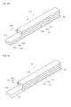
- FIGS. 4A and 4B illustrate perspective views of an electrode assembly according to an exemplary embodiments of the present invention where the short-circuit induction member and the electrode assembly are not yet wound.
- FIGS. 5A and 5B illustrate sectional views of an electrode assembly of a secondary battery according to another exemplary embodiment of the present invention.
- FIG. 6A is a graph of voltage-temperature characteristics of a secondary battery without a short-circuit induction member that is puncture or collapsed
- FIG. 6B is a graph of voltage-temperature characteristics when a secondary battery including a short-circuit induction member is punctured or collapsed.
- the short-circuit induction member or short-circuit member is at an exterior of the electrode assembly, the short-circuit induction member is firstly short circuited when the secondary battery is punctured or collapsed.
- the short-circuit induction member has relatively low resistivity, a small amount of heat is generated when a short circuit occurs, and the electric energy of the secondary battery is quickly consumed.
- the resistivity of the short-circuit induction member is lower than that of the case or the electrode assembly. Therefore, the safety and reliability of a secondary battery may be significantly improved.
- FIG. 1A is a perspective view of a secondary battery according to a first exemplary embodiment of the present invention
- FIG. 1B is a cross-sectional view of FIG. 1A
- FIG. 1C is a perspective view of an electrode assembly and an electrode terminal according to the first exemplary embodiment of the present invention.
- FIG. 1A depicts a secondary battery 100 having improved safety against puncture and collapse according to an embodiment of the present invention.
- the secondary battery includes an electrode assembly 110, a can 120, a first electrode terminal 130, a second electrode terminal 140, a cap plate 150, and a short-circuit induction member 160.
- the can 120 is referred to as a case.
- the electrode assembly 110 includes a first electrode, a separator, and a second electrode.
- the wound electrode assembly 110 has a jelly roll shape.
- the first electrode may be a positive electrode, and the second electrode may be a negative electrode.
- the first electrode may be a negative electrode, and the second electrode may be a positive electrode.
- the first electrode includes a first metal foil and a first active material.
- the first metal foil may be formed of aluminum, and the first active material may include lithium based oxide.
- the second electrode includes a second metal foil and a second active material.
- the second metal foil When the second electrode is the negative electrode, the second metal foil may be formed of copper, and the second active material may include graphite.
- embodiments of the present invention are not limited to these materials.
- the separator may be formed of porous polyethylene (PE), polypropylene (PP), or other equivalents.
- the separator may be on both lateral surfaces of the first electrode or the second electrode.
- the first electrode may include a first uncoated region in which a positive electrode active material is not included. The first uncoated region may protrude beyond one side of the separator.
- the second electrode may include a second uncoated region in which a negative electrode active material is not included. The second uncoated region may protrude beyond the other side of the separator. That is, the first uncoated region and the second uncoated region may protrude beyond the separator in opposite directions. This structure will be described below in more detail.
- the can 120 includes two wide lateral surfaces 121a and 121b, two narrow lateral surfaces 122a and 122b, and one bottom surface 123. Also, the can 120 has an open upper portion.
- the electrode assembly 110 is received into the can 120 together with an electrolyte.
- the first uncoated region and the second uncoated region of the electrode assembly 110 extend toward the two narrow lateral surfaces 122a and 122b of the can 120, respectively.
- the can 120 may be formed of aluminum, copper, iron, stainless steel, ceramic, and polymer, or any other suitable material.
- the can 120 may be substantially electrically connected to one of the first electrode or the second electrode. That is, the can 120 may have one polarity, either positive or negative. When the can is polarized, an inner surface of the can 120 may be coated with an electrical insulating material to prevent the can 120 from being unnecessarily electrically short circuited.
- the first electrode terminal 130 and the second electrode terminal 140 are electrically connected to the first electrode and the second electrode, respectively. That is, the first electrode terminal 130 may be welded to the first electrode, and the second electrode terminal 140 may be welded to the short-circuit induction member 160 and the second electrode. More specifically, the first electrode terminal 130 may be welded to the first uncoated region of the first electrode of the electrode assembly 110. Also, the second electrode terminal 140 may be welded to the second uncoated region of the second electrode of the electrode assembly 110 together with the short-circuit induction member 160. This structure will be described below in more detail.
- Reference numerals 160a and 160b of FIG. 1B represent marks at which the short-circuit induction member 160 and the first uncoated regions of the first electrode of the electrode assembly 110 may be welded to each other.
- Reference numeral 160c represents marks at which the first uncoated region of the first electrode of the electrode assembly 110 may be welded to the first electrode terminal 130.
- reference numerals 160d and 160e of the FIG. 1B represent marks at which the short-circuit induction member 160 and the second uncoated region of the second electrode of the electrode assembly 110 may be welded to each other.
- Reference numeral 160f represents a mark at which the short-circuit induction member 160 and the second uncoated region of the second electrode of the electrode assembly 110 may be welded to the second electrode terminal 140.
- the first electrode terminal 130 includes a welding region 131, a first extension 132, a second extension 133, and a bolt extension 134.
- the welding region 131 is inserted into the first uncoated region of the first electrode of the electrode assembly 110.
- the second electrode terminal 140 includes a welding region 141, a first extension part 142, a second extension part 143, and a bolt extension 144.
- the welding region 141 is inserted into the second uncoated region of the second electrode of the electrode assembly 110.
- each of the bolt extensions 134 and 144 of the first electrode terminal 130 and the second electrode terminal 140 pass through the cap plate 150 to protrude to an exterior of the case.
- the cap plate 150 allows the first electrode terminal 130 and the second electrode terminal 140 to protrude to an exterior of the case and additionally covers the can 120.
- a boundary between the cap plate 150 and the can 120 may be welded using a laser.
- each of the bolt extensions 134 and 144 of the first electrode terminal 130 and the second electrode terminal 140 pass through the cap plate 150.
- the cap plate 150 and the can 120 have the same polarity as the first electrode terminal 130.
- the cap plate 150 and the can 120 have a positive charge.
- the cap plate 150 and the can 120 have a negative charge.
- an insulating material may be disposed on an outer surface of the bolt extension 144 of the second electrode terminal 140.
- the second electrode terminal 140 may be electrically insulated from the cap plate 150.
- the first electrode terminal 130 has a positive charge.
- Nuts 135 and 145 are coupled to the bolt extensions 134 and 144 of the first electrode terminal 130 and the second electrode terminal 140, respectively.
- the first electrode terminal 130 and the second electrode terminal 140 are firmly fixed to the cap plate 150.
- an electrolyte plug 152 may be coupled to the cap plate 150.
- a safety vent 153 having a relatively thin thickness may be disposed on the cap plate 150.
- the cap plate 150 may be formed of the same material as the can 120.
- the short-circuit induction member 160 extends from the first electrode or the second electrode and is wound around the outermost periphery of the electrode assembly 110. Thus, when the secondary battery 110 is punctured or collapsed, the short-circuit induction member 160 is firstly short circuited together with the can 120. Since the short-circuit induction member 160 extends from the first electrode or the second electrode of the electrode assembly 110, the short-circuit induction member short circuits the entire electrode assembly 110.
- the short-circuit induction member 160 is wound about one to seven times around the exterior or outer circumference of the electrode assembly 110.
- a number of windings of one refers to the case that the short-circuit induction member 160 is wound around the outer circumference of the electrode assembly 110 such that the electrode assembly 110 is fully covered by the short-circuit induction member 160 without any overlap of the ends of the short-circuit induction member 160. If the number of windings is more than one, an overlap of the short-circuit induction member 160 with itself is established.
- the short-circuit induction member 160 may not cause a short circuit when the secondary battery 100 is punctured or collapsed because the short-circuit induction member 160 does not cover the entirety of the electrode assembly. In other words, the puncture or collapse could occur at a place where the short-circuit induction member 160 is not present. Furthermore, when the short-circuit induction member 160 is wound around the electrode assembly 110 more than seven times, the electrode assembly 110 may not be inserted into the can 120 because the electrode assembly 110 with the short-circuit induction member 160 may now be too big.
- the electrode assembly 110 may be required to have a reduced size, reducing the capacity of the secondary battery 100.
- the separator 113a is formed at an approximately central portion of the electrode assembly 110.
- the first electrode 111 extends beyond one side of the separator 113a, and the short-circuit induction member may extend beyond the other side of the separator 113a. That is, the first electrode 111 may protrude in a front direction of the separator 113a, and the short-circuit induction member 160 may protrude in a rear direction of the separator 113a.
- the relation between the short-circuit induction member 160 and the electrode assembly 110 will be described below in more detail.
- FIG. 2A illustrates a process in which a short-circuit induction member is wound around an electrode assembly in a secondary battery having improved safety against puncture and collapse according to an embodiment
- FIGS. 2B and 2C illustrate enlarged views of region 2a and region 2b of FIG. 2A .
- the short-circuit induction member 160 may extend from the second electrode 112 of the electrode assembly 110 and be wound around the electrode assembly 110. That is, the sum of lengths of the second electrode 112 and the short-circuit induction member 160 is longer than that of the first electrode 111.
- the short-circuit induction member 160 is manufactured and wound during a manufacturing process of the electrode assembly 110.
- a sealing tape 165 is adhered to an exterior of the short-circuit induction member to prevent the short-circuit induction member 160 from being loosed from the electrode assembly 110.
- the short-circuit induction member 160 includes a second metal foil 162a extending from the second electrode 112 of the electrode assembly 110 and a second active material 162b.
- the second metal foil 162a may include a copper foil
- the second active material 162b may include graphite.
- the separators 113a and 113b may be disposed on both lateral surfaces of the short-circuit induction member 160, respectively.
- the short-circuit induction member 160 is wound about two times in FIG. 2B , it is not limited thereto.
- the separator 113a, the first electrode 111, the separator 113b, and the second electrode 112 are sequentially disposed at positions adjacent to the short-circuit induction member 160.
- the first electrode 111 may include a first metal foil 111a (e.g., aluminum foil) and a first active material 111b (e.g., lithium-based oxide).
- the second electrode 112 may include a second metal foil 112a (e.g., copper foil) and a second active material 112b (e.g., graphite).
- the second electrode 112 may extend farther than the first electrode 111.
- the short-circuit induction member 160 and the second electrode 112 have the same material and configuration.
- the short-circuit induction member 160 may be formed of copper, aluminum, or any other suitable material.
- a short-circuit induction member 260 may include only the second metal foil extending from the second electrode 112 of the electrode assembly 110. That is, the short-circuit induction member 260 may not include the second active material.
- the short-circuit induction member 260 may include copper foil.
- the separators 113a and 113b may be disposed on both lateral surfaces of the short-circuit induction member 260, respectively. Also, although the short-circuit induction member 260 is wound about two times in FIG. 2B , embodiments of the present invention are not limited thereto.
- a short circuit between the short-circuit induction member 160 or 260 and an inner surface of the can 120 occurs.
- the short-circuit induction member 160 or 260 may have a negative charge
- the can 120 may have a positive charge. Since a portion of the second electrode 112 extends to form the short-circuit induction member 160 or 260, a short circuit between the can 120 and the short-circuit induction member 160 short circuits the entire electrode assembly 110.
- the short-circuit induction member 260 on which the active material is not disposed has a low resistivity, little heat is generated. That is, the secondary battery 100 does not generate much heat, and the electric energy of the secondary battery 110 is quickly removed.
- the secondary battery 100 does not exceed a temperature ranging from about 50°C to about 100°C when the secondary battery 100 is punctured or collapsed.
- the can 120 may be formed of a metal having low resistivity, when the secondary battery 100 is punctured or collapsed, the secondary battery 100 generates relatively little heat, and the electric energy of the secondary battery 100 is quickly removed.
- FIG. 3 illustrates a process in which an electrode assembly, a short-circuit induction member, and an electrode terminal are welded to each other according to an exemplary embodiment of the present invention.
- the electrode assembly 110 and the short-circuit induction member 160 extends beyond the electrode assembly 110 by a certain distance, and the short-circuit induction member 160 and the electrode from which the short-circuit induction member 160 is extending from may be welded to each other in a plurality of regions.
- the welding process may include a resistance welding process, an ultrasonic welding process, and a laser welding process. However, any suitable welding process may be used.
- Arrows 170a and 170b of FIG. 3 represent welding points between the electrode assembly 110 and the short-circuit induction member 160.
- the electrode terminal 140 may be coupled to the electrode assembly 110. That is, the welding region 141 of the electrode terminal 140 may be coupled to the electrode assembly 110. More specifically, the welding region 141 of the first electrode terminal 140, which is not electrically connected to the cap plate, is coupled to a gap in the first uncoated region of the second electrode of the electrode assembly 110.
- the welding region of the first electrode terminal is coupled to a gap in the first uncoated region of the first electrode of the electrode assembly 110. Only the second electrode terminal 140 is illustrated in FIG. 3 .
- the welding region 141, the second uncoated region of the second electrode of the electrode assembly 110, and the short-circuit induction member 160 may be welded to each other. That is, after the second uncoated region of the second electrode of the electrode assembly 110 and the short-circuit induction member 160 are attached to the welding region 141 of the electrode terminal 140, the welding region 141, the electrode assembly 110, and the second uncoated region may be welded to each other using suitable resistance welding, ultrasonic welding, laser welding, or any other suitable welding method.
- Reference numeral 170c of FIG. 3 represents a welding point between the welding region 141 of the electrode terminal 140, the electrode assembly 110, and the short-circuit induction member 160.
- the welding region 131 and the first uncoated region of the first electrode of the electrode assembly 110 may be welded to each other.
- FIGS. 4A and 4B illustrate perspective views of an electrode assembly according to an exemplary embodiments of the present invention where the short-circuit induction member and the electrode assembly are not yet wound.
- the short-circuit induction member 160 extends from an end in a longitudinal direction of the second electrode 112 by a given length. That is, the second electrode 112 and the -short-circuit induction member 160 together have a length greater than that of the first electrode 111.
- the short-circuit induction member 160 has a length which allows to fully cover the outer circumference of the electrode assembly 110 at least ones.
- the separator 113a is disposed on an upper portion of the short-circuit induction member 160 extending from the second electrode 112, the separator 113a has a length equal to or greater than the sum of lengths of the second electrode 112 and the short-circuit induction member 160.
- the short-circuit induction member 160 has the substantially same structure as the second electrode 112. That is, the short-circuit induction member 160 may include the second metal foil 162a, the second active material 162b coated on the second metal foil 162a, and the second uncoated region 162c which extends beyond at least one side of the separator 113a, preferably perpendicular to the longitudinal direction of the separator 113a.
- the second electrode 112 may include the second metal foil 112a, the second active material 112b coated on the second metal foil 112a, and the second uncoated region 112c which extends beyond at least one side of the separator 113a, preferably perpendicular to the longitudinal direction of the separator 113a.
- the second uncoated region 162c of the short-circuit induction member 160 and the second uncoated region 112c of the second electrode 112 extend beyond the separator 113a. That is, the second uncoated region 162c and the second uncoated region 112c protrude in a front direction of the separator 113a. In Fig. 4a , the second uncoated region 162c and the second uncoated region 112c protrude from the separator 113a on a first side along the length of the separator 113a.
- the first electrode 111 is disposed on the separator 113a.
- the first electrode 111 includes the first metal foil 111a, the first active material 111b coated on the first metal foil 111a, and the first uncoated region 111c extends beyond the separator 113a.
- the other separator 113b is disposed on the first electrode 111.
- the first uncoated region 111c of the first electrode 111 extends beyond the separator 113b. That is, the first uncoated region 111c protrudes in a rear direction of the separator 113b. In Fig. 4a , the first uncoated region 111c protrudes from the separator 113a on a second side along the length of the separator 113a, the second side being the opposite side of the first side.
- the first uncoated region 111c of the first electrode 111 protrudes in a direction opposite to that of the second uncoated region 112c of the second electrode 112.
- the second uncoated region 162c of the short-circuit induction member 160 protrudes in a direction equal to that of the second uncoated region 112c and opposite to that of the first uncoated region 111c.
- the second electrode 112, the separator 113a, the first electrode 111 and the separator 113b may be stacked and wound in a substantially counterclockwise direction by a wind shaft 201.
- the short-circuit induction member 160 together with the second electrode 112 from which it extends has a length greater than that of the first electrode 111
- the short-circuit induction member 160 is wound about one to about seven times around an exterior surface or outer circumference of the electrode assembly.
- the wind shaft 201 may be separated from the electrode assembly after a winding process of the electrode assembly is completed.
- the second uncoated region 112c of the second electrode 112 and the second uncoated region 160c of the short-circuit induction member 160 are electrically connected and welded to each other.
- the short-circuit induction member 260 may extend from the end, in the longitudinal direction, of the second electrode 112 of the electrode assembly 110 by a given length.
- the second active material may not be included on the short-circuit induction member 260. That is, a metal of the short-circuit induction member 260 may be exposed.
- the separator 113a is disposed on the upper portion of the short-circuit induction member 260 on which the active material is not disposed to prevent the short-circuit induction member 260 from being electrically short circuited to the inner surface of the can after the short-circuit induction member 260 is wound.
- the short-circuit induction member 260 may be made of the second metal foil that is one of the components of the second electrode 112.
- the short-circuit induction member 260 is formed of a material having a relatively low resistivity, the secondary battery 110 generates less heat, and the energy of the secondary battery may be quickly consumed when the secondary battery 110 is punctured or collapsed.
- FIGS. 5A and 5B illustrate sectional views of an electrode assembly of a secondary battery according to another exemplary embodiment of the present invention.
- an electrode assembly 210 may be provided in a pair 110.
- two short-circuit induction member 160 may be independently wound around each of the electrode assemblies 110.
- Each of the electrode assemblies 110 is electrically connected to the electrode terminal 240.
- the electrode terminal 240 includes two welding regions 241, a first extension 242, a second extension 243, and a bolt extension 244.
- the welding region 241 is inserted into each of the electrode assemblies 110.
- the short-circuit induction member 160 and the electrode assemblies 110 are welded to the welding regions 241 using a suitable welding method. As a result, the capacity of a secondary battery increases, and also, the electrode assembly 210 is quickly and forcedly short circuited when the secondary battery is punctured or collapsed.
- an electrode assembly 310 may be provided in a pair 110.
- one short-circuit induction member 360 may be integrally wound around the pair of electrode assemblies 110. That is, one short-circuit induction member 360 may completely cover the pair of electrode assemblies 110.
- the capacity of a secondary battery increases, and also, the secondary battery is quickly and forcedly short circuited.
- the electrode assemblies 310 may be easily handled.
- FIG. 6A is a graph of voltage-temperature characteristics of a secondary battery without a short-circuit induction member that is puncture or collapsed
- FIG. 6B is a graph of voltage-temperature characteristics when a secondary battery including a short-circuit induction member is punctured or collapsed.
- the X-axis represents an elapsed time (in minutes).
- a left Y-axis represents a voltage (V), and a right Y-axis represents a temperature (°C).
- a test was performed under following conditions: residual capacity is about 90%, an open circuit voltage is about 4.1 V, and a nail having a diameter of about 3 mm is penetrated into the secondary battery at a speed of about 80 mm/sec.
- a voltage of the secondary battery dropped slightly, and then rose again. Thereafter, the voltage of the secondary battery represented by the upper line of Fig. 6A dropped in a smoothly curved shape to approach about 0 V.
- the secondary battery gradually increased in temperature as shown by the lower line in Fig. 6A , the secondary battery did not exceed a temperature of about 100°C. That is, the secondary battery was maintained at a temperature ranging from about 50°C to about 100°C.
- the safety and reliability of the secondary battery are both improved.
- a voltage of the secondary battery represented by the upper line in Fig. 6B dropped to about 0 V.
- the secondary battery gradually increased in temperature as shown by the lower line in Fig. 6B , the secondary battery did not exceed a temperature of about 70°C. That is, the secondary battery was maintained at a temperature ranging from about 50°C to about 70°C.
- the safety and reliability of the secondary battery are both improved.
- the short-circuit induction member includes the active material (e.g., graphite)
- the manufacturing process of a rechargeable battery is simplified.
- the secondary battery increases up to a temperature ranging from about 50°C to about 100°C when the secondary battery is punctured and collapsed.
- the short-circuit induction member does not include active material
- a separate processes a process for removing the active material, or a process for preventing the active material from being coated
- the manufacturing process thereof may be complicated.
- the temperature inside the secondary battery increases only up to a temperature ranging from about 50°C to about 70°C when the secondary battery is punctured and collapsed. Therefore, the safety and reliability of the secondary battery having a short-circuit induction member without active material is relatively improved when compared to a secondary battery having a short-circuit induction member including an active material.
- the short-circuit induction member may in one embodiment not include an active material but only a metal, for example, copper with a resistivity of about 1.72 ⁇ 10 -8 ⁇ m, or aluminum with a resistivity of about 2.75 ⁇ 10 -8 ⁇ m. Copper and aluminum have a lower resistivity compared to graphite used as a negative active material, which has a resistivity of about 7 ⁇ 10 -6 ⁇ m to about 12 ⁇ 10 -6 ⁇ m and lithium-based oxide used as a positive active material, which is almost nonconductive.
- a metal for example, copper with a resistivity of about 1.72 ⁇ 10 -8 ⁇ m, or aluminum with a resistivity of about 2.75 ⁇ 10 -8 ⁇ m. Copper and aluminum have a lower resistivity compared to graphite used as a negative active material, which has a resistivity of about 7 ⁇ 10 -6 ⁇ m to about 12 ⁇ 10 -6 ⁇ m and lithium-based oxide used as a positive active material, which is almost nonconductive.
Abstract
Description
- The following description relates to a rechargeable secondary battery and more particularly to a rechargeable secondary battery with improved safety against puncture and collapse.
- Lithium ion secondary batteries are widely used as a power source for small electronic devices such as notebook computers and cellular phones. In addition, because lithium ion secondary batteries have high output density, high capacity, and are light weight, they are also being used in hybrid and electric automobiles.
- Lithium ion secondary batteries used as a power source of automobiles should satisfy safety and reliability requirements under severe conditions. There is a plurality of test categories for safety, among which, three of the most extreme test categories include puncture, collapse, and overcharge.
- The puncture and collapse tests are performed to estimate secondary battery related damage in the event of a car accident and thus are very important test categories for safety. Specifically, in nail puncture tests, such as a nail penetration test, and collapse tests, the battery should not excessively increase in temperature after puncture or collapse.
- Aspects of the present invention are directed toward a rechargeable battery having improved safety against puncture and collapse.
- Accordingly, a rechargeable battery is provided, comprising an electrode assembly having a first electrode, a second electrode, and a separator interposed between the first and the second electrodes, a case for mounting the electrode assembly therein, and a cap plate for closing an opening of the case. Additionally, a short-circuit induction member is provided between the case and the electrode assembly, wherein the case is electrically coupled to the first electrode of the electrode assembly and the short-circuit induction member is electrically coupled to the second electrode.
- Advantageously, due to the provision of a short circuit induction member, the safety and reliability of a secondary battery is improved.
- The short-circuit induction member preferably covers the outermost periphery of the electrode assembly in at least a single layer.
- Since the short circuit induction member is formed at an exterior of the electrode assembly, the short circuit induction member is firstly short circuited when the secondary battery is punctured or collapsed.
- The short-circuit induction member is preferably wound around the outermost periphery or outer circumference of the electrode assembly at least an entire perimeter of the electrode assembly, and/or is preferably wound around the outermost periphery or outer circumference of the electrode assembly at most seven times.
- When the short-circuit induction member is wound around the electrode assembly less than ones, the short-circuit induction member may not cause a short circuit when the secondary battery is punctured or collapsed because the short-circuit induction member does not cover the entire electrode assembly. When the short-circuit induction member is wound around the electrode assembly more than seven times, the electrode assembly may be required to have a reduced size in order to fit into a can, thereby reducing the capacity of the secondary battery.
- Preferably, the first electrode and the second electrode are wound-up with the separator in between and the short-circuit induction member extends from the second electrode. In this way, the short-circuit induction member can be formed easily.
- The short-circuit induction member and the second electrode are preferably integrally formed. In one embodiment they may be formed in one piece.
- The sum of the lengths of the second electrode and the short-circuit induction member is preferably larger than the length of the first electrode. The sum of the lengths of the second electrode and the short-circuit induction member may have a value sufficient to allow a full coverage of the outer periphery or circumference of the electrode assembly.
- Preferably, the short-circuit induction member has the same structure, and/or material as the second electrode. In this way, the short-circuit induction member can be formed effortless.
- The first electrode may include a first metal foil and a first active material, the second electrode plate may include a second metal foil and a second active material, and the short-circuit induction member may include the second metal foil extending from the second electrode of the electrode assembly and the second active material.
- Advantageously, the safety and reliability of the secondary battery are improved since such a battery does not exceed a temperature of 100°C when the battery is punctured or collapsed.
- The short-circuit induction member may alternatively comprise the second metal foil extending from the second electrode on which an active material is not disposed.
- As the short-circuit induction member on which the active material is not disposed has a low resistivity, little heat is generated. Further, the electric energy of the secondary battery is quickly removed.
- The separator is preferably disposed on both surfaces of the short-circuit induction member such that the separator is placed between the short-circuit induction member and the case. Advantageously, the short-circuit induction member is accordingly prevented from being electrically short-circuited to the inner surface of the can during assembly.
- A second electrode assembly may be provided inside the battery, and the short-circuit induction member may be independently wound around each of the electrode assemblies, or is integrally wound around the pair of electrode assemblies.
- If such electrode assemblies are completely covered by a single short-circuit induction member, the electrode assemblies can be handled easily.
- The short circuit induction member may comprise a metal foil selected from the group consisting of copper and aluminum, and/or may comprise or consist of a material being different than that of the case.
- Copper and aluminum advantageously have a lower resistivity than graphite. Thus, when the short-circuit induction member formed of a copper or aluminum material is short circuited, a large current is consumed, and little heat is generated.
- A first electrode terminal may be welded to the first electrode and a second terminal may be welded to the short-circuit induction member and the second electrode.
- The first electrode preferably comprises a first uncoated region not coated with the active material and extending to a first side of the electrode assembly, the second electrode preferably comprises a second uncoated region extending to a second side different from the first side of the electrode assembly, and the short circuit induction member is preferably coupled to the second uncoated region of the second electrode. The short circuit induction member may be welded to the second uncoated region of the second electrode.
- The short-circuit induction member is preferably adapted to form a short-circuit of the electrode assembly and the case when the battery is punctured or collapsed by electrically connecting the short-circuit induction member with the case.
- Additionally, a method of forming a rechargeable battery is provided, the method comprising the steps of providing an electrode assembly comprising a first electrode, a second electrode and a separator inside a case of a battery, connecting a short-circuit induction member to the electrode assembly, and winding the short-circuit induction member around the outermost periphery of the electrode assembly at least an entire perimeter of the electrode assembly, wherein the short-circuit induction member is adapted to form a short-circuit of the electrode assembly with the case when the battery is punctured or collapsed.
-
FIG. 1A is a perspective view of a secondary battery according to a first exemplary embodiment of the present invention,FIG. 1B is a cross-sectional view ofFIG. 1A , andFIG. 1C is a perspective view of an electrode assembly and electrode terminal according to the first exemplary embodiment of the present invention. -
FIG. 2A illustrates a process in which a short-circuit induction member is wound around an electrode assembly in a secondary battery having improved safety against puncture and collapse according to an embodiment, andFIGS. 2B and 2C illustrate enlarged views ofregion 2a andregion 2b ofFIG. 2A . -
FIG. 3 illustrates a process in which an electrode assembly, a short-circuit induction member, and an electrode terminal are welded to each other according to an exemplary embodiment of the present invention. -
FIGS. 4A and 4B illustrate perspective views of an electrode assembly according to an exemplary embodiments of the present invention where the short-circuit induction member and the electrode assembly are not yet wound. -
FIGS. 5A and 5B illustrate sectional views of an electrode assembly of a secondary battery according to another exemplary embodiment of the present invention. -
FIG. 6A is a graph of voltage-temperature characteristics of a secondary battery without a short-circuit induction member that is puncture or collapsed, andFIG. 6B is a graph of voltage-temperature characteristics when a secondary battery including a short-circuit induction member is punctured or collapsed. - Exemplary embodiments will now be described more fully with reference to the accompanying drawings; however, they may be embodied in different forms and should not be construed as limited to the embodiments set forth herein. Rather, these embodiments are provided so that the disclosure is thorough and complete, and will fully convey the scope of the invention to those skilled in the art.
- In rechargeable secondary batteries according to embodiments of the present invention, because the short-circuit induction member or short-circuit member is at an exterior of the electrode assembly, the short-circuit induction member is firstly short circuited when the secondary battery is punctured or collapsed. As the short-circuit induction member has relatively low resistivity, a small amount of heat is generated when a short circuit occurs, and the electric energy of the secondary battery is quickly consumed. Preferably, the resistivity of the short-circuit induction member is lower than that of the case or the electrode assembly. Therefore, the safety and reliability of a secondary battery may be significantly improved.
-
FIG. 1A is a perspective view of a secondary battery according to a first exemplary embodiment of the present invention,FIG. 1B is a cross-sectional view ofFIG. 1A , andFIG. 1C is a perspective view of an electrode assembly and an electrode terminal according to the first exemplary embodiment of the present invention. -
FIG. 1A depicts asecondary battery 100 having improved safety against puncture and collapse according to an embodiment of the present invention. The secondary battery includes anelectrode assembly 110, acan 120, afirst electrode terminal 130, asecond electrode terminal 140, acap plate 150, and a short-circuit induction member 160. In some embodiments, thecan 120 is referred to as a case. - The
electrode assembly 110 includes a first electrode, a separator, and a second electrode. Thewound electrode assembly 110 has a jelly roll shape. The first electrode may be a positive electrode, and the second electrode may be a negative electrode. Alternatively, the first electrode may be a negative electrode, and the second electrode may be a positive electrode. The first electrode includes a first metal foil and a first active material. When the first electrode is the positive electrode, the first metal foil may be formed of aluminum, and the first active material may include lithium based oxide. Also, the second electrode includes a second metal foil and a second active material. When the second electrode is the negative electrode, the second metal foil may be formed of copper, and the second active material may include graphite. However, embodiments of the present invention are not limited to these materials. The separator may be formed of porous polyethylene (PE), polypropylene (PP), or other equivalents. The separator may be on both lateral surfaces of the first electrode or the second electrode. Furthermore, the first electrode may include a first uncoated region in which a positive electrode active material is not included. The first uncoated region may protrude beyond one side of the separator. Also, the second electrode may include a second uncoated region in which a negative electrode active material is not included. The second uncoated region may protrude beyond the other side of the separator. That is, the first uncoated region and the second uncoated region may protrude beyond the separator in opposite directions. This structure will be described below in more detail. - The can 120 includes two
wide lateral surfaces narrow lateral surfaces bottom surface 123. Also, thecan 120 has an open upper portion. Theelectrode assembly 110 is received into thecan 120 together with an electrolyte. Here, the first uncoated region and the second uncoated region of theelectrode assembly 110 extend toward the twonarrow lateral surfaces can 120, respectively. The can 120 may be formed of aluminum, copper, iron, stainless steel, ceramic, and polymer, or any other suitable material. Furthermore, thecan 120 may be substantially electrically connected to one of the first electrode or the second electrode. That is, thecan 120 may have one polarity, either positive or negative. When the can is polarized, an inner surface of thecan 120 may be coated with an electrical insulating material to prevent thecan 120 from being unnecessarily electrically short circuited. - The
first electrode terminal 130 and thesecond electrode terminal 140 are electrically connected to the first electrode and the second electrode, respectively. That is, thefirst electrode terminal 130 may be welded to the first electrode, and thesecond electrode terminal 140 may be welded to the short-circuit induction member 160 and the second electrode. More specifically, thefirst electrode terminal 130 may be welded to the first uncoated region of the first electrode of theelectrode assembly 110. Also, thesecond electrode terminal 140 may be welded to the second uncoated region of the second electrode of theelectrode assembly 110 together with the short-circuit induction member 160. This structure will be described below in more detail. -
Reference numerals FIG. 1B represent marks at which the short-circuit induction member 160 and the first uncoated regions of the first electrode of theelectrode assembly 110 may be welded to each other.Reference numeral 160c represents marks at which the first uncoated region of the first electrode of theelectrode assembly 110 may be welded to thefirst electrode terminal 130. Also,reference numerals FIG. 1B represent marks at which the short-circuit induction member 160 and the second uncoated region of the second electrode of theelectrode assembly 110 may be welded to each other.Reference numeral 160f represents a mark at which the short-circuit induction member 160 and the second uncoated region of the second electrode of theelectrode assembly 110 may be welded to thesecond electrode terminal 140. - The
first electrode terminal 130 includes awelding region 131, afirst extension 132, asecond extension 133, and abolt extension 134. Thewelding region 131 is inserted into the first uncoated region of the first electrode of theelectrode assembly 110. Also, thesecond electrode terminal 140 includes awelding region 141, afirst extension part 142, asecond extension part 143, and abolt extension 144. Thewelding region 141 is inserted into the second uncoated region of the second electrode of theelectrode assembly 110. In addition, each of thebolt extensions first electrode terminal 130 and thesecond electrode terminal 140 pass through thecap plate 150 to protrude to an exterior of the case. - The
cap plate 150 allows thefirst electrode terminal 130 and thesecond electrode terminal 140 to protrude to an exterior of the case and additionally covers thecan 120. A boundary between thecap plate 150 and thecan 120 may be welded using a laser. In addition, each of thebolt extensions first electrode terminal 130 and thesecond electrode terminal 140 pass through thecap plate 150. As thebolt extension 134 of thefirst electrode terminal 130 directly contacts thecap plate 150, thecap plate 150 and thecan 120 have the same polarity as thefirst electrode terminal 130. When thefirst electrode terminal 130 has a positive charge, thecap plate 150 and thecan 120 have a positive charge. Also, when thefirst electrode terminal 130 has a negative charge, thecap plate 150 and thecan 120 have a negative charge. In addition, an insulating material may be disposed on an outer surface of thebolt extension 144 of thesecond electrode terminal 140. Thus, thesecond electrode terminal 140 may be electrically insulated from thecap plate 150. Hereinafter, it will be assumed that thefirst electrode terminal 130 has a positive charge. -
Nuts bolt extensions first electrode terminal 130 and thesecond electrode terminal 140, respectively. Thus, thefirst electrode terminal 130 and thesecond electrode terminal 140 are firmly fixed to thecap plate 150. Furthermore, anelectrolyte plug 152 may be coupled to thecap plate 150. Asafety vent 153 having a relatively thin thickness may be disposed on thecap plate 150. Thecap plate 150 may be formed of the same material as thecan 120. - The short-
circuit induction member 160 extends from the first electrode or the second electrode and is wound around the outermost periphery of theelectrode assembly 110. Thus, when thesecondary battery 110 is punctured or collapsed, the short-circuit induction member 160 is firstly short circuited together with thecan 120. Since the short-circuit induction member 160 extends from the first electrode or the second electrode of theelectrode assembly 110, the short-circuit induction member short circuits theentire electrode assembly 110. - The short-
circuit induction member 160 is wound about one to seven times around the exterior or outer circumference of theelectrode assembly 110. A number of windings of one refers to the case that the short-circuit induction member 160 is wound around the outer circumference of theelectrode assembly 110 such that theelectrode assembly 110 is fully covered by the short-circuit induction member 160 without any overlap of the ends of the short-circuit induction member 160. If the number of windings is more than one, an overlap of the short-circuit induction member 160 with itself is established. When the number of windings of the short-circuit induction member 160 is is less than one, the short-circuit induction member 160 may not cause a short circuit when thesecondary battery 100 is punctured or collapsed because the short-circuit induction member 160 does not cover the entirety of the electrode assembly. In other words, the puncture or collapse could occur at a place where the short-circuit induction member 160 is not present. Furthermore, when the short-circuit induction member 160 is wound around theelectrode assembly 110 more than seven times, theelectrode assembly 110 may not be inserted into thecan 120 because theelectrode assembly 110 with the short-circuit induction member 160 may now be too big. As a result, in order to be able to insert anelectrode assembly 110 that includes a short-circuit induction member 160 that has been wound around theelectrode assembly 110 more than seven times, theelectrode assembly 110 may be required to have a reduced size, reducing the capacity of thesecondary battery 100. - The
separator 113a is formed at an approximately central portion of theelectrode assembly 110. Thefirst electrode 111 extends beyond one side of theseparator 113a, and the short-circuit induction member may extend beyond the other side of theseparator 113a. That is, thefirst electrode 111 may protrude in a front direction of theseparator 113a, and the short-circuit induction member 160 may protrude in a rear direction of theseparator 113a. The relation between the short-circuit induction member 160 and theelectrode assembly 110 will be described below in more detail. -
FIG. 2A illustrates a process in which a short-circuit induction member is wound around an electrode assembly in a secondary battery having improved safety against puncture and collapse according to an embodiment, andFIGS. 2B and 2C illustrate enlarged views ofregion 2a andregion 2b ofFIG. 2A . - Referring to 2A, the short-
circuit induction member 160 may extend from thesecond electrode 112 of theelectrode assembly 110 and be wound around theelectrode assembly 110. That is, the sum of lengths of thesecond electrode 112 and the short-circuit induction member 160 is longer than that of thefirst electrode 111. Thus, the short-circuit induction member 160 is manufactured and wound during a manufacturing process of theelectrode assembly 110. In addition, after the short-circuit induction member 160 is wound, a sealingtape 165 is adhered to an exterior of the short-circuit induction member to prevent the short-circuit induction member 160 from being loosed from theelectrode assembly 110. - Referring to
FIG. 2B , the short-circuit induction member 160 includes asecond metal foil 162a extending from thesecond electrode 112 of theelectrode assembly 110 and a secondactive material 162b. Here, thesecond metal foil 162a may include a copper foil, and the secondactive material 162b may include graphite. In addition, theseparators circuit induction member 160, respectively. Also, although the short-circuit induction member 160 is wound about two times inFIG. 2B , it is not limited thereto. - The
separator 113a, thefirst electrode 111, theseparator 113b, and thesecond electrode 112 are sequentially disposed at positions adjacent to the short-circuit induction member 160. - The
first electrode 111 may include afirst metal foil 111a (e.g., aluminum foil) and a firstactive material 111b (e.g., lithium-based oxide). Also, thesecond electrode 112 may include asecond metal foil 112a (e.g., copper foil) and a secondactive material 112b (e.g., graphite). - To form the short-
circuit induction member 160, thesecond electrode 112 may extend farther than thefirst electrode 111. Thus, the short-circuit induction member 160 and thesecond electrode 112 have the same material and configuration. However, the short-circuit induction member 160 may be formed of copper, aluminum, or any other suitable material. - Referring to
FIG. 2C , a short-circuit induction member 260 may include only the second metal foil extending from thesecond electrode 112 of theelectrode assembly 110. That is, the short-circuit induction member 260 may not include the second active material. The short-circuit induction member 260 may include copper foil. In addition, theseparators circuit induction member 260, respectively. Also, although the short-circuit induction member 260 is wound about two times inFIG. 2B , embodiments of the present invention are not limited thereto. - When the
secondary battery 100 having the above-described structure is punctured or collapsed, a short circuit between the short-circuit induction member can 120 occurs. For example, the short-circuit induction member can 120 may have a positive charge. Since a portion of thesecond electrode 112 extends to form the short-circuit induction member can 120 and the short-circuit induction member 160 short circuits theentire electrode assembly 110. As the short-circuit induction member 260 on which the active material is not disposed has a low resistivity, little heat is generated. That is, thesecondary battery 100 does not generate much heat, and the electric energy of thesecondary battery 110 is quickly removed. - For example, the
secondary battery 100 according to an embodiment does not exceed a temperature ranging from about 50°C to about 100°C when thesecondary battery 100 is punctured or collapsed. In addition, since thecan 120 may be formed of a metal having low resistivity, when thesecondary battery 100 is punctured or collapsed, thesecondary battery 100 generates relatively little heat, and the electric energy of thesecondary battery 100 is quickly removed. -
FIG. 3 illustrates a process in which an electrode assembly, a short-circuit induction member, and an electrode terminal are welded to each other according to an exemplary embodiment of the present invention. - Referring to
FIG. 3 , theelectrode assembly 110 and the short-circuit induction member 160 extends beyond theelectrode assembly 110 by a certain distance, and the short-circuit induction member 160 and the electrode from which the short-circuit induction member 160 is extending from may be welded to each other in a plurality of regions. The welding process may include a resistance welding process, an ultrasonic welding process, and a laser welding process. However, any suitable welding process may be used.Arrows FIG. 3 represent welding points between theelectrode assembly 110 and the short-circuit induction member 160. - The
electrode terminal 140 may be coupled to theelectrode assembly 110. That is, thewelding region 141 of theelectrode terminal 140 may be coupled to theelectrode assembly 110. More specifically, thewelding region 141 of thefirst electrode terminal 140, which is not electrically connected to the cap plate, is coupled to a gap in the first uncoated region of the second electrode of theelectrode assembly 110. - At this time, the welding region of the first electrode terminal is coupled to a gap in the first uncoated region of the first electrode of the
electrode assembly 110. Only thesecond electrode terminal 140 is illustrated inFIG. 3 . - The
welding region 141, the second uncoated region of the second electrode of theelectrode assembly 110, and the short-circuit induction member 160 may be welded to each other. That is, after the second uncoated region of the second electrode of theelectrode assembly 110 and the short-circuit induction member 160 are attached to thewelding region 141 of theelectrode terminal 140, thewelding region 141, theelectrode assembly 110, and the second uncoated region may be welded to each other using suitable resistance welding, ultrasonic welding, laser welding, or any other suitable welding method. - Reference numeral 170c of
FIG. 3 represents a welding point between thewelding region 141 of theelectrode terminal 140, theelectrode assembly 110, and the short-circuit induction member 160. Here, thewelding region 131 and the first uncoated region of the first electrode of theelectrode assembly 110 may be welded to each other. -
FIGS. 4A and 4B illustrate perspective views of an electrode assembly according to an exemplary embodiments of the present invention where the short-circuit induction member and the electrode assembly are not yet wound. - Referring to
FIG. 4A , the short-circuit induction member 160 extends from an end in a longitudinal direction of thesecond electrode 112 by a given length. That is, thesecond electrode 112 and the -short-circuit induction member 160 together have a length greater than that of thefirst electrode 111. Preferably, the short-circuit induction member 160 has a length which allows to fully cover the outer circumference of theelectrode assembly 110 at least ones. Also, since theseparator 113a is disposed on an upper portion of the short-circuit induction member 160 extending from thesecond electrode 112, theseparator 113a has a length equal to or greater than the sum of lengths of thesecond electrode 112 and the short-circuit induction member 160. - Also, since the
second electrode 112 of theelectrode assembly 110 extends to form the short-circuit induction member 160, the short-circuit induction member 160 has the substantially same structure as thesecond electrode 112. That is, the short-circuit induction member 160 may include thesecond metal foil 162a, the secondactive material 162b coated on thesecond metal foil 162a, and the seconduncoated region 162c which extends beyond at least one side of theseparator 113a, preferably perpendicular to the longitudinal direction of theseparator 113a. - The
second electrode 112 may include thesecond metal foil 112a, the secondactive material 112b coated on thesecond metal foil 112a, and the seconduncoated region 112c which extends beyond at least one side of theseparator 113a, preferably perpendicular to the longitudinal direction of theseparator 113a. - The second
uncoated region 162c of the short-circuit induction member 160 and the seconduncoated region 112c of thesecond electrode 112 extend beyond theseparator 113a. That is, the seconduncoated region 162c and the seconduncoated region 112c protrude in a front direction of theseparator 113a. InFig. 4a , the seconduncoated region 162c and the seconduncoated region 112c protrude from theseparator 113a on a first side along the length of theseparator 113a. - In addition, the
first electrode 111 is disposed on theseparator 113a. Thefirst electrode 111 includes thefirst metal foil 111a, the firstactive material 111b coated on thefirst metal foil 111a, and the firstuncoated region 111c extends beyond theseparator 113a. Furthermore, theother separator 113b is disposed on thefirst electrode 111. The firstuncoated region 111c of thefirst electrode 111 extends beyond theseparator 113b. That is, the firstuncoated region 111c protrudes in a rear direction of theseparator 113b. InFig. 4a , the firstuncoated region 111c protrudes from theseparator 113a on a second side along the length of theseparator 113a, the second side being the opposite side of the first side. - Thus, the first
uncoated region 111c of thefirst electrode 111 protrudes in a direction opposite to that of the seconduncoated region 112c of thesecond electrode 112. Also, the seconduncoated region 162c of the short-circuit induction member 160 protrudes in a direction equal to that of the seconduncoated region 112c and opposite to that of the firstuncoated region 111c. - The
second electrode 112, theseparator 113a, thefirst electrode 111 and theseparator 113b may be stacked and wound in a substantially counterclockwise direction by awind shaft 201. Thus, as the short-circuit induction member 160 together with thesecond electrode 112 from which it extends has a length greater than that of thefirst electrode 111, the short-circuit induction member 160 is wound about one to about seven times around an exterior surface or outer circumference of the electrode assembly. Thewind shaft 201 may be separated from the electrode assembly after a winding process of the electrode assembly is completed. - Therefore, the second
uncoated region 112c of thesecond electrode 112 and the seconduncoated region 160c of the short-circuit induction member 160 are electrically connected and welded to each other. - Referring to
FIG. 4B , the short-circuit induction member 260 may extend from the end, in the longitudinal direction, of thesecond electrode 112 of theelectrode assembly 110 by a given length. Here, the second active material may not be included on the short-circuit induction member 260. That is, a metal of the short-circuit induction member 260 may be exposed. Theseparator 113a is disposed on the upper portion of the short-circuit induction member 260 on which the active material is not disposed to prevent the short-circuit induction member 260 from being electrically short circuited to the inner surface of the can after the short-circuit induction member 260 is wound. The short-circuit induction member 260 may be made of the second metal foil that is one of the components of thesecond electrode 112. - Therefore, since the short-
circuit induction member 260 is formed of a material having a relatively low resistivity, thesecondary battery 110 generates less heat, and the energy of the secondary battery may be quickly consumed when thesecondary battery 110 is punctured or collapsed. -
FIGS. 5A and 5B illustrate sectional views of an electrode assembly of a secondary battery according to another exemplary embodiment of the present invention. - Referring to
FIG. 5A , anelectrode assembly 210 may be provided in apair 110. In addition, two short-circuit induction member 160 may be independently wound around each of theelectrode assemblies 110. Each of theelectrode assemblies 110 is electrically connected to theelectrode terminal 240. Here, theelectrode terminal 240 includes twowelding regions 241, afirst extension 242, asecond extension 243, and abolt extension 244. Also, thewelding region 241 is inserted into each of theelectrode assemblies 110. The short-circuit induction member 160 and theelectrode assemblies 110 are welded to thewelding regions 241 using a suitable welding method. As a result, the capacity of a secondary battery increases, and also, theelectrode assembly 210 is quickly and forcedly short circuited when the secondary battery is punctured or collapsed. - Referring to
FIG. 5B , anelectrode assembly 310 may be provided in apair 110. Moreover, one short-circuit induction member 360 may be integrally wound around the pair ofelectrode assemblies 110. That is, one short-circuit induction member 360 may completely cover the pair ofelectrode assemblies 110. Thus, the capacity of a secondary battery increases, and also, the secondary battery is quickly and forcedly short circuited. Furthermore, since theelectrode assemblies 310 are completely covered by one short-circuit induction member 360, theelectrode assemblies 310 may be easily handled. -
FIG. 6A is a graph of voltage-temperature characteristics of a secondary battery without a short-circuit induction member that is puncture or collapsed, andFIG. 6B is a graph of voltage-temperature characteristics when a secondary battery including a short-circuit induction member is punctured or collapsed. - In
FIGS. 6A and 6B , the X-axis represents an elapsed time (in minutes). A left Y-axis represents a voltage (V), and a right Y-axis represents a temperature (°C). Also, a test was performed under following conditions: residual capacity is about 90%, an open circuit voltage is about 4.1 V, and a nail having a diameter of about 3 mm is penetrated into the secondary battery at a speed of about 80 mm/sec. - Referring to
FIG. 6A , in a case of a secondary battery in which a short-circuit induction member includes an active material, after the penetration started, a voltage of the secondary battery dropped slightly, and then rose again. Thereafter, the voltage of the secondary battery represented by the upper line ofFig. 6A dropped in a smoothly curved shape to approach about 0 V. - Although the secondary battery gradually increased in temperature as shown by the lower line in
Fig. 6A , the secondary battery did not exceed a temperature of about 100°C. That is, the secondary battery was maintained at a temperature ranging from about 50°C to about 100°C. Thus, in the case of the secondary battery in which the short-circuit induction member includes the active material, since the secondary battery does not exceed the permissible temperature when the secondary battery is punctured and collapsed, the safety and reliability of the secondary battery are both improved. - Referring to
FIG. 6B , in a case of a secondary battery in which a short-circuit induction member does not include the active material, after the puncture started, a voltage of the secondary battery represented by the upper line inFig. 6B dropped to about 0 V. Although the secondary battery gradually increased in temperature as shown by the lower line inFig. 6B , the secondary battery did not exceed a temperature of about 70°C. That is, the secondary battery was maintained at a temperature ranging from about 50°C to about 70°C. Thus, in the case of the secondary battery in which the short-circuit induction member does not include the active material, as the secondary battery does not exceed the permissible temperature when the secondary battery is punctured and collapsed, the safety and reliability of the secondary battery are both improved. - In addition, in the case where the short-circuit induction member includes the active material (e.g., graphite), as the second electrode is extended by a certain length to form the short-circuit induction member, the manufacturing process of a rechargeable battery is simplified. However, it was confirmed that the secondary battery increases up to a temperature ranging from about 50°C to about 100°C when the secondary battery is punctured and collapsed.
- In the case where the short-circuit induction member does not include active material, since a separate processes (a process for removing the active material, or a process for preventing the active material from being coated) is performed on the second electrode, the manufacturing process thereof may be complicated. However, the temperature inside the secondary battery increases only up to a temperature ranging from about 50°C to about 70°C when the secondary battery is punctured and collapsed. Therefore, the safety and reliability of the secondary battery having a short-circuit induction member without active material is relatively improved when compared to a secondary battery having a short-circuit induction member including an active material.
- As above-described, the short-circuit induction member may in one embodiment not include an active material but only a metal, for example, copper with a resistivity of about 1.72 × 10⁻⁸ Ω·m, or aluminum with a resistivity of about 2.75 × 10⁻⁸ Ω·m. Copper and aluminum have a lower resistivity compared to graphite used as a negative active material, which has a resistivity of about 7 × 10⁻⁶ Ω·m to about 12 × 10-6 Ω·m and lithium-based oxide used as a positive active material, which is almost nonconductive. Thus, when the short-circuit induction member formed of a copper or aluminum material is short circuited, a large current is consumed, and little heat is generated.
- While this disclosure has been described in connection with what is presently considered to be practical exemplary embodiments, it is understood that the invention is not limited to the disclosed embodiments, but, on the contrary, is intended to cover various modifications and equivalent arrangements included within the scope of the appended claims.
Claims (15)
- A rechargeable battery (100) comprising:an electrode assembly (110) having a first electrode (111), a second electrode (112), and a separator (113) interposed between the first and the second electrodes (111, 112);a case (120) for mounting the electrode assembly (110) therein; anda cap plate (150) for closing an opening of the case (120),characterized in thata short-circuit induction member (160) is provided between the case (120) and the electrode assembly (110), wherein the case (120) is electrically coupled to the first electrode (111) of the electrode assembly (110) and the short-circuit induction member (160) is electrically coupled to the second electrode (112).
- Rechargeable battery (100) according to claim 1, wherein the short-circuit induction member (160) covers the outermost periphery of the electrode assembly (110) in at least a single layer.
- Rechargeable battery (100) according to claims 1 or 2, wherein the short-circuit induction member (160) is wound around the outermost periphery of the electrode assembly (110) at least an entire perimeter of the electrode assembly (110), and/or is wound around the outermost periphery of the electrode assembly (110) at most seven times.
- Rechargeable battery (100) according to one of the previous claims, wherein the first electrode (111) and the second electrode (112) are wound-up with the separator (113) in between and the short-circuit induction member (160) extends from the second electrode (112).
- Rechargeable battery (100) according to one of the previous claims, wherein the short-circuit induction member (160) and the second electrode (112) are integrally formed.
- Rechargeable battery (100) according to one of the previous claims, wherein the sum of the lengths of the second electrode (112) and the short-circuit induction member (160) is larger than the length of the first electrode (111).
- Rechargeable battery (100) according to one of the previous claims, wherein the short-circuit induction member (160) has the same structure, and/or material as the second electrode (112).
- Rechargeable battery (100) according to one of the previous claims, wherein the first electrode (111) includes a first metal foil (111a) and a first active material (111b), the second electrode plate (112) includes a second metal foil (112a) and a second active material (112b), and the short-circuit induction member (160) includes:the second metal foil (162a) extending from the second electrode (112) of the electrode assembly (110) and the second active material (162b); orthe second metal foil (162a) extending from the second electrode (112) on which an active material (112a) is not disposed.
- Rechargeable battery (100) according to one of the previous claims, wherein the separator (113) is disposed on both surfaces of the short-circuit induction member (160) such that the separator (113) is placed between the short-circuit induction member (160) and the case (120).
- Rechargeable battery (100) according to one of the previous claims, wherein a second electrode assembly is provided inside the battery (100), and the short-circuit induction member (160):is independently wound around each of the electrode assemblies (110); oris integrally wound around the pair of electrode assemblies (110).
- Rechargeable battery (100) according to one of the previous claims, wherein the short circuit induction member (160) comprises a metal foil selected from the group consisting of copper and aluminum, and/or comprises a material being different than that of the case (120).
- Rechargeable battery (100) according to one of the previous claims, wherein a first electrode terminal (130) is welded to the first electrode (111) and a second terminal (140) is welded to the short-circuit induction member (160) and the second electrode (112).
- Rechargeable battery (100) according to one of the previous claims, wherein the first electrode (111) comprises a first uncoated region (111c) not coated with the active material (111b) and extending to a first side of the electrode assembly (110), the second electrode (112) comprises a second uncoated region (112c) extending to a second side different from the first side of the electrode assembly, and the short circuit induction member (160) is coupled to the second uncoated region (112c) of the second electrode (112), and/or is welded to the second uncoated region (112c) of the second electrode (112).
- Rechargeable battery (100) according to one of the previous claims, wherein the short-circuit induction member (160) is adapted to form a short-circuit of the electrode assembly (110) and the case (120) when the battery (100) is punctured or collapsed by electrically connecting the short-circuit induction member (160) with the case (120).
- Method of forming a rechargeable battery (100) comprising the steps of:providing an electrode assembly (110) comprising a first electrode (111), a second electrode (112) and a separator (113) inside a case (120) of a battery (100);connecting a short-circuit induction member (160) to the electrode assembly (110);
winding the short-circuit induction member (160) around the outermost periphery of the electrode assembly (110) at least an entire perimeter of the electrode assembly (110), wherein the short-circuit induction member (160) is adapted to form a short-circuit of the electrode assembly (110) with the case (120) when the battery (100) is punctured or collapsed.
Applications Claiming Priority (2)
| Application Number | Priority Date | Filing Date | Title |
|---|---|---|---|
| US23764709P | 2009-08-27 | 2009-08-27 | |
| US12/610,214 US8039147B2 (en) | 2009-08-27 | 2009-10-30 | Rechargeable secondary battery having improved safety against puncture and collapse |
Publications (2)
| Publication Number | Publication Date |
|---|---|
| EP2293366A1 true EP2293366A1 (en) | 2011-03-09 |
| EP2293366B1 EP2293366B1 (en) | 2013-04-17 |
Family
ID=43030608
Family Applications (1)
| Application Number | Title | Priority Date | Filing Date |
|---|---|---|---|
| EP10165931.6A Active EP2293366B1 (en) | 2009-08-27 | 2010-06-15 | Rechargeable secondary battery having improved safety against puncture and collapse |
Country Status (5)
| Country | Link |
|---|---|
| US (1) | US8039147B2 (en) |
| EP (1) | EP2293366B1 (en) |
| JP (1) | JP5319613B2 (en) |
| KR (1) | KR101156313B1 (en) |
| CN (1) | CN102005596B (en) |
Cited By (25)
| Publication number | Priority date | Publication date | Assignee | Title |
|---|---|---|---|---|
| EP2410594A1 (en) * | 2010-07-23 | 2012-01-25 | SB LiMotive Co., Ltd. | Rechargeable battery |
| WO2014048618A1 (en) * | 2012-09-26 | 2014-04-03 | Robert Bosch Gmbh | Battery cell having a current collector for housing contacting |
| WO2014087743A1 (en) * | 2012-12-04 | 2014-06-12 | 株式会社豊田自動織機 | Electricity storage device |
| US8758429B2 (en) | 2005-07-15 | 2014-06-24 | Micell Technologies, Inc. | Polymer coatings containing drug powder of controlled morphology |
| US8795762B2 (en) | 2010-03-26 | 2014-08-05 | Battelle Memorial Institute | System and method for enhanced electrostatic deposition and surface coatings |
| US8834913B2 (en) | 2008-12-26 | 2014-09-16 | Battelle Memorial Institute | Medical implants and methods of making medical implants |
| US8852625B2 (en) | 2006-04-26 | 2014-10-07 | Micell Technologies, Inc. | Coatings containing multiple drugs |
| US8900651B2 (en) | 2007-05-25 | 2014-12-02 | Micell Technologies, Inc. | Polymer films for medical device coating |
| US9433516B2 (en) | 2007-04-17 | 2016-09-06 | Micell Technologies, Inc. | Stents having controlled elution |
| US9486431B2 (en) | 2008-07-17 | 2016-11-08 | Micell Technologies, Inc. | Drug delivery medical device |
| US9510856B2 (en) | 2008-07-17 | 2016-12-06 | Micell Technologies, Inc. | Drug delivery medical device |
| US9539593B2 (en) | 2006-10-23 | 2017-01-10 | Micell Technologies, Inc. | Holder for electrically charging a substrate during coating |
| US9737642B2 (en) | 2007-01-08 | 2017-08-22 | Micell Technologies, Inc. | Stents having biodegradable layers |
| US9789233B2 (en) | 2008-04-17 | 2017-10-17 | Micell Technologies, Inc. | Stents having bioabsorbable layers |
| US9981072B2 (en) | 2009-04-01 | 2018-05-29 | Micell Technologies, Inc. | Coated stents |
| US10117972B2 (en) | 2011-07-15 | 2018-11-06 | Micell Technologies, Inc. | Drug delivery medical device |
| US10188772B2 (en) | 2011-10-18 | 2019-01-29 | Micell Technologies, Inc. | Drug delivery medical device |
| US10232092B2 (en) | 2010-04-22 | 2019-03-19 | Micell Technologies, Inc. | Stents and other devices having extracellular matrix coating |
| US10272606B2 (en) | 2013-05-15 | 2019-04-30 | Micell Technologies, Inc. | Bioabsorbable biomedical implants |
| US10464100B2 (en) | 2011-05-31 | 2019-11-05 | Micell Technologies, Inc. | System and process for formation of a time-released, drug-eluting transferable coating |
| US10835396B2 (en) | 2005-07-15 | 2020-11-17 | Micell Technologies, Inc. | Stent with polymer coating containing amorphous rapamycin |
| US11039943B2 (en) | 2013-03-12 | 2021-06-22 | Micell Technologies, Inc. | Bioabsorbable biomedical implants |
| US11369498B2 (en) | 2010-02-02 | 2022-06-28 | MT Acquisition Holdings LLC | Stent and stent delivery system with improved deliverability |
| US11426494B2 (en) | 2007-01-08 | 2022-08-30 | MT Acquisition Holdings LLC | Stents having biodegradable layers |
| US11904118B2 (en) | 2010-07-16 | 2024-02-20 | Micell Medtech Inc. | Drug delivery medical device |
Families Citing this family (18)
| Publication number | Priority date | Publication date | Assignee | Title |
|---|---|---|---|---|
| US9023513B2 (en) * | 2009-08-27 | 2015-05-05 | Samsung Sdi Co., Ltd. | Rechargeable secondary battery having improved safety against puncture and collapse |
| KR101217071B1 (en) * | 2010-02-18 | 2012-12-31 | 로베르트 보쉬 게엠베하 | Rechargeable battery |
| CN102122728A (en) * | 2011-01-28 | 2011-07-13 | 福建南平南孚电池有限公司 | Method for winding cylindrical lithium-iron disulfide battery core |
| US8551633B2 (en) * | 2011-08-18 | 2013-10-08 | Samsung Sdi Co., Ltd. | Secondary battery |
| US8883332B2 (en) * | 2011-12-09 | 2014-11-11 | Samsung Sdi Co., Ltd. | Rechargeable secondary battery |
| US9627677B2 (en) * | 2011-12-23 | 2017-04-18 | Samsung Sdi Co., Ltd. | Rechargeable battery |
| KR101706403B1 (en) | 2012-04-20 | 2017-02-14 | 삼성에스디아이 주식회사 | Secondary Battery |
| US9203117B2 (en) | 2012-05-04 | 2015-12-01 | Samsung Sdi Co., Ltd. | Rechargeable secondary battery |
| KR101715964B1 (en) | 2012-06-04 | 2017-03-13 | 삼성에스디아이 주식회사 | Rechargeable secondary battery |
| KR101934398B1 (en) * | 2012-07-04 | 2019-01-02 | 삼성에스디아이 주식회사 | Secondary battery |
| DE102013200714A1 (en) * | 2013-01-18 | 2014-07-24 | Robert Bosch Gmbh | Protection mechanism for battery cells |
| DE102013203620A1 (en) * | 2013-03-04 | 2014-09-04 | Robert Bosch Gmbh | Battery cell i.e. lithium ion battery cell, for battery module for e.g. hybrid car for transportation of human, has electrode assembly provided with housing and inactive layer with insulation layer made of high-melting polymer or ceramic |
| JP6120000B2 (en) * | 2013-12-26 | 2017-04-26 | 株式会社豊田自動織機 | Power storage device |
| CN104934646A (en) * | 2014-03-21 | 2015-09-23 | 深圳市沃特玛电池有限公司 | Method for improving security of ternary-material polymer lithium ion battery |
| JP6407665B2 (en) * | 2014-11-05 | 2018-10-17 | 株式会社東芝 | Assembled battery |
| CN108807829B (en) | 2014-11-10 | 2020-09-15 | 东莞新能源科技有限公司 | Battery cell and electrochemical device |
| JP6867746B2 (en) * | 2015-03-20 | 2021-05-12 | 株式会社Gsユアサ | Power storage element |
| CN106450137B (en) | 2016-11-15 | 2019-02-22 | 宁德时代新能源科技股份有限公司 | Secondary battery |
Citations (4)
| Publication number | Priority date | Publication date | Assignee | Title |
|---|---|---|---|---|
| EP0780920A1 (en) * | 1994-09-27 | 1997-06-25 | Asahi Kasei Kogyo Kabushiki Kaisha | Non-aqueous type cell |
| US20030044677A1 (en) * | 2001-08-24 | 2003-03-06 | Yoshinori Naruoka | Nonaqueous electrolyte secondary battery |
| US20030129479A1 (en) * | 2001-12-18 | 2003-07-10 | Noriyoshi Munenaga | Cell |
| EP2048736A1 (en) * | 2007-10-09 | 2009-04-15 | Samsung SDI Co., Ltd. | Lithium secondary battery |
Family Cites Families (8)
| Publication number | Priority date | Publication date | Assignee | Title |
|---|---|---|---|---|
| JP3200340B2 (en) * | 1994-09-27 | 2001-08-20 | 旭化成株式会社 | Non-aqueous battery |
| JPH10261429A (en) * | 1997-03-18 | 1998-09-29 | Japan Storage Battery Co Ltd | Battery |
| US7332242B2 (en) | 2000-09-01 | 2008-02-19 | Itochu Corporation | Lithium-based battery having extensible, ion-impermeable polymer covering on the battery container |
| JP2002093402A (en) * | 2000-09-14 | 2002-03-29 | Yuasa Corp | Sealed battery |
| JP2003187856A (en) * | 2001-12-18 | 2003-07-04 | Japan Storage Battery Co Ltd | Battery |
| US20030215700A1 (en) * | 2002-04-04 | 2003-11-20 | Kenichiro Hosoda | Nonaqueous electrolyte secondary battery |
| KR100590006B1 (en) * | 2004-06-23 | 2006-06-14 | 삼성에스디아이 주식회사 | Secondary battery and electrodes assembly |
| JP4907996B2 (en) | 2005-01-14 | 2012-04-04 | パナソニック株式会社 | Non-aqueous electrolyte secondary battery |
-
2009
- 2009-10-30 US US12/610,214 patent/US8039147B2/en active Active
- 2009-12-23 KR KR1020090129891A patent/KR101156313B1/en active IP Right Grant
-
2010
- 2010-06-08 JP JP2010131076A patent/JP5319613B2/en active Active
- 2010-06-08 CN CN201010198527.1A patent/CN102005596B/en active Active
- 2010-06-15 EP EP10165931.6A patent/EP2293366B1/en active Active
Patent Citations (4)
| Publication number | Priority date | Publication date | Assignee | Title |
|---|---|---|---|---|
| EP0780920A1 (en) * | 1994-09-27 | 1997-06-25 | Asahi Kasei Kogyo Kabushiki Kaisha | Non-aqueous type cell |
| US20030044677A1 (en) * | 2001-08-24 | 2003-03-06 | Yoshinori Naruoka | Nonaqueous electrolyte secondary battery |
| US20030129479A1 (en) * | 2001-12-18 | 2003-07-10 | Noriyoshi Munenaga | Cell |
| EP2048736A1 (en) * | 2007-10-09 | 2009-04-15 | Samsung SDI Co., Ltd. | Lithium secondary battery |
Cited By (43)
| Publication number | Priority date | Publication date | Assignee | Title |
|---|---|---|---|---|
| US11911301B2 (en) | 2005-07-15 | 2024-02-27 | Micell Medtech Inc. | Polymer coatings containing drug powder of controlled morphology |
| US10898353B2 (en) | 2005-07-15 | 2021-01-26 | Micell Technologies, Inc. | Polymer coatings containing drug powder of controlled morphology |
| US8758429B2 (en) | 2005-07-15 | 2014-06-24 | Micell Technologies, Inc. | Polymer coatings containing drug powder of controlled morphology |
| US10835396B2 (en) | 2005-07-15 | 2020-11-17 | Micell Technologies, Inc. | Stent with polymer coating containing amorphous rapamycin |
| US9827117B2 (en) | 2005-07-15 | 2017-11-28 | Micell Technologies, Inc. | Polymer coatings containing drug powder of controlled morphology |
| US11007307B2 (en) | 2006-04-26 | 2021-05-18 | Micell Technologies, Inc. | Coatings containing multiple drugs |
| US8852625B2 (en) | 2006-04-26 | 2014-10-07 | Micell Technologies, Inc. | Coatings containing multiple drugs |
| US11850333B2 (en) | 2006-04-26 | 2023-12-26 | Micell Medtech Inc. | Coatings containing multiple drugs |
| US9415142B2 (en) | 2006-04-26 | 2016-08-16 | Micell Technologies, Inc. | Coatings containing multiple drugs |
| US9737645B2 (en) | 2006-04-26 | 2017-08-22 | Micell Technologies, Inc. | Coatings containing multiple drugs |
| US9539593B2 (en) | 2006-10-23 | 2017-01-10 | Micell Technologies, Inc. | Holder for electrically charging a substrate during coating |
| US11426494B2 (en) | 2007-01-08 | 2022-08-30 | MT Acquisition Holdings LLC | Stents having biodegradable layers |
| US10617795B2 (en) | 2007-01-08 | 2020-04-14 | Micell Technologies, Inc. | Stents having biodegradable layers |
| US9737642B2 (en) | 2007-01-08 | 2017-08-22 | Micell Technologies, Inc. | Stents having biodegradable layers |
| US9486338B2 (en) | 2007-04-17 | 2016-11-08 | Micell Technologies, Inc. | Stents having controlled elution |
| US9433516B2 (en) | 2007-04-17 | 2016-09-06 | Micell Technologies, Inc. | Stents having controlled elution |
| US9775729B2 (en) | 2007-04-17 | 2017-10-03 | Micell Technologies, Inc. | Stents having controlled elution |
| US8900651B2 (en) | 2007-05-25 | 2014-12-02 | Micell Technologies, Inc. | Polymer films for medical device coating |
| US10350333B2 (en) | 2008-04-17 | 2019-07-16 | Micell Technologies, Inc. | Stents having bioabsorable layers |
| US9789233B2 (en) | 2008-04-17 | 2017-10-17 | Micell Technologies, Inc. | Stents having bioabsorbable layers |
| US9981071B2 (en) | 2008-07-17 | 2018-05-29 | Micell Technologies, Inc. | Drug delivery medical device |
| US10350391B2 (en) | 2008-07-17 | 2019-07-16 | Micell Technologies, Inc. | Drug delivery medical device |
| US9486431B2 (en) | 2008-07-17 | 2016-11-08 | Micell Technologies, Inc. | Drug delivery medical device |
| US9510856B2 (en) | 2008-07-17 | 2016-12-06 | Micell Technologies, Inc. | Drug delivery medical device |
| US8834913B2 (en) | 2008-12-26 | 2014-09-16 | Battelle Memorial Institute | Medical implants and methods of making medical implants |
| US9981072B2 (en) | 2009-04-01 | 2018-05-29 | Micell Technologies, Inc. | Coated stents |
| US10653820B2 (en) | 2009-04-01 | 2020-05-19 | Micell Technologies, Inc. | Coated stents |
| US11369498B2 (en) | 2010-02-02 | 2022-06-28 | MT Acquisition Holdings LLC | Stent and stent delivery system with improved deliverability |
| US8795762B2 (en) | 2010-03-26 | 2014-08-05 | Battelle Memorial Institute | System and method for enhanced electrostatic deposition and surface coatings |
| US9687864B2 (en) | 2010-03-26 | 2017-06-27 | Battelle Memorial Institute | System and method for enhanced electrostatic deposition and surface coatings |
| US10232092B2 (en) | 2010-04-22 | 2019-03-19 | Micell Technologies, Inc. | Stents and other devices having extracellular matrix coating |
| US11904118B2 (en) | 2010-07-16 | 2024-02-20 | Micell Medtech Inc. | Drug delivery medical device |
| EP2410594A1 (en) * | 2010-07-23 | 2012-01-25 | SB LiMotive Co., Ltd. | Rechargeable battery |
| US8968908B2 (en) | 2010-07-23 | 2015-03-03 | Samsung Sdi Co., Ltd. | Rechargeable battery |
| US10464100B2 (en) | 2011-05-31 | 2019-11-05 | Micell Technologies, Inc. | System and process for formation of a time-released, drug-eluting transferable coating |
| US10729819B2 (en) | 2011-07-15 | 2020-08-04 | Micell Technologies, Inc. | Drug delivery medical device |
| US10117972B2 (en) | 2011-07-15 | 2018-11-06 | Micell Technologies, Inc. | Drug delivery medical device |
| US10188772B2 (en) | 2011-10-18 | 2019-01-29 | Micell Technologies, Inc. | Drug delivery medical device |
| US9799911B2 (en) | 2012-09-26 | 2017-10-24 | Robert Bosch Gmbh | Battery cell comprising a current collector for making contact with a housing |
| WO2014048618A1 (en) * | 2012-09-26 | 2014-04-03 | Robert Bosch Gmbh | Battery cell having a current collector for housing contacting |
| WO2014087743A1 (en) * | 2012-12-04 | 2014-06-12 | 株式会社豊田自動織機 | Electricity storage device |
| US11039943B2 (en) | 2013-03-12 | 2021-06-22 | Micell Technologies, Inc. | Bioabsorbable biomedical implants |
| US10272606B2 (en) | 2013-05-15 | 2019-04-30 | Micell Technologies, Inc. | Bioabsorbable biomedical implants |
Also Published As
| Publication number | Publication date |
|---|---|
| JP5319613B2 (en) | 2013-10-16 |
| CN102005596B (en) | 2014-06-18 |
| JP2011049147A (en) | 2011-03-10 |
| CN102005596A (en) | 2011-04-06 |
| KR20110022509A (en) | 2011-03-07 |
| US8039147B2 (en) | 2011-10-18 |
| KR101156313B1 (en) | 2012-06-13 |
| US20100279160A1 (en) | 2010-11-04 |
| EP2293366B1 (en) | 2013-04-17 |
Similar Documents
| Publication | Publication Date | Title |
|---|---|---|
| EP2293366B1 (en) | Rechargeable secondary battery having improved safety against puncture and collapse | |
| EP2293367B1 (en) | Rechargeable secondary battery having improved safety against puncture and collapse | |
| KR100509606B1 (en) | Jelly-roll type battery unit and winding method thereof and lithum secondary battery using the same | |
| US10454140B2 (en) | Electrode body for use in non-aqueous electrolyte secondary battery and non-aqueous electrolyte secondary battery | |
| KR101182904B1 (en) | Electrode Assembly and Secondary battery with the Same and Method of thereof | |
| KR100958649B1 (en) | Battery unit and the winding method thereof and lithum secondary battery using the same | |
| KR100947982B1 (en) | Electrode assembly body and Pouch type lithium rechargeable battery having the same | |
| US8728644B2 (en) | Rechargeable battery | |
| KR102279223B1 (en) | Electrode assembly having protection tape and rechargeable battery having thereof | |
| US11289782B2 (en) | Secondary battery | |
| US9698407B2 (en) | Rechargeable battery | |
| US20170062795A1 (en) | Battery module | |
| KR101002498B1 (en) | Electrode assembly and secondary battery having the same | |
| US20150287976A1 (en) | Rechargeable battery having protective circuit module | |
| KR102277352B1 (en) | Electrode assembly and rechargeable battery including the same | |
| KR102188429B1 (en) | Jelly-Roll Type Electrode Having Uncoated Part of Electrode Active Material | |
| KR100472510B1 (en) | Jelly-roll type battery unit and winding method of the same and lithum secondary battery using the same | |
| KR20040042373A (en) | Cylindrical secondary battery | |
| KR102227806B1 (en) | Secondary battery | |
| JP2002025627A (en) | Nonaqueous film package secondary battery | |
| KR20140146936A (en) | Battery cell with improved safety and method of manufacturing the same |
Legal Events
| Date | Code | Title | Description |
|---|---|---|---|
| PUAI | Public reference made under article 153(3) epc to a published international application that has entered the european phase |
Free format text: ORIGINAL CODE: 0009012 |
|
| 17P | Request for examination filed |
Effective date: 20100615 |
|
| AK | Designated contracting states |
Kind code of ref document: A1 Designated state(s): AL AT BE BG CH CY CZ DE DK EE ES FI FR GB GR HR HU IE IS IT LI LT LU LV MC MK MT NL NO PL PT RO SE SI SK SM TR |
|
| AX | Request for extension of the european patent |
Extension state: BA ME RS |
|
| RAP1 | Party data changed (applicant data changed or rights of an application transferred) |
Owner name: SB LIMOTIVE CO., LTD. |
|
| 17Q | First examination report despatched |
Effective date: 20120612 |
|
| REG | Reference to a national code |
Ref country code: DE Ref legal event code: R079 Ref document number: 602010006173 Country of ref document: DE Free format text: PREVIOUS MAIN CLASS: H01M0002260000 Ipc: H01M0010058700 |
|
| GRAP | Despatch of communication of intention to grant a patent |
Free format text: ORIGINAL CODE: EPIDOSNIGR1 |
|
| RIC1 | Information provided on ipc code assigned before grant |
Ipc: H01M 10/42 20060101ALI20121025BHEP Ipc: H01M 10/04 20060101ALI20121025BHEP Ipc: H01M 10/0525 20100101ALI20121025BHEP Ipc: H01M 2/34 20060101ALI20121025BHEP Ipc: H01M 2/26 20060101ALI20121025BHEP Ipc: H01M 10/0587 20100101AFI20121025BHEP |
|
| RAP1 | Party data changed (applicant data changed or rights of an application transferred) |
Owner name: ROBERT BOSCH GMBH Owner name: SAMSUNG SDI CO., LTD. |
|
| GRAS | Grant fee paid |
Free format text: ORIGINAL CODE: EPIDOSNIGR3 |
|
| GRAA | (expected) grant |
Free format text: ORIGINAL CODE: 0009210 |
|
| AK | Designated contracting states |
Kind code of ref document: B1 Designated state(s): AL AT BE BG CH CY CZ DE DK EE ES FI FR GB GR HR HU IE IS IT LI LT LU LV MC MK MT NL NO PL PT RO SE SI SK SM TR |
|
| REG | Reference to a national code |
Ref country code: GB Ref legal event code: FG4D |
|
| REG | Reference to a national code |
Ref country code: CH Ref legal event code: EP |
|
| REG | Reference to a national code |
Ref country code: IE Ref legal event code: FG4D |
|
| REG | Reference to a national code |
Ref country code: AT Ref legal event code: REF Ref document number: 607793 Country of ref document: AT Kind code of ref document: T Effective date: 20130515 |
|
| REG | Reference to a national code |
Ref country code: DE Ref legal event code: R096 Ref document number: 602010006173 Country of ref document: DE Effective date: 20130613 |
|
| REG | Reference to a national code |
Ref country code: AT Ref legal event code: MK05 Ref document number: 607793 Country of ref document: AT Kind code of ref document: T Effective date: 20130417 |
|
| REG | Reference to a national code |
Ref country code: LT Ref legal event code: MG4D |
|
| REG | Reference to a national code |
Ref country code: NL Ref legal event code: VDEP Effective date: 20130417 |
|
| PG25 | Lapsed in a contracting state [announced via postgrant information from national office to epo] |
Ref country code: ES Free format text: LAPSE BECAUSE OF FAILURE TO SUBMIT A TRANSLATION OF THE DESCRIPTION OR TO PAY THE FEE WITHIN THE PRESCRIBED TIME-LIMIT Effective date: 20130728 Ref country code: SE Free format text: LAPSE BECAUSE OF FAILURE TO SUBMIT A TRANSLATION OF THE DESCRIPTION OR TO PAY THE FEE WITHIN THE PRESCRIBED TIME-LIMIT Effective date: 20130417 Ref country code: AT Free format text: LAPSE BECAUSE OF FAILURE TO SUBMIT A TRANSLATION OF THE DESCRIPTION OR TO PAY THE FEE WITHIN THE PRESCRIBED TIME-LIMIT Effective date: 20130417 Ref country code: GR Free format text: LAPSE BECAUSE OF FAILURE TO SUBMIT A TRANSLATION OF THE DESCRIPTION OR TO PAY THE FEE WITHIN THE PRESCRIBED TIME-LIMIT Effective date: 20130718 Ref country code: FI Free format text: LAPSE BECAUSE OF FAILURE TO SUBMIT A TRANSLATION OF THE DESCRIPTION OR TO PAY THE FEE WITHIN THE PRESCRIBED TIME-LIMIT Effective date: 20130417 Ref country code: PT Free format text: LAPSE BECAUSE OF FAILURE TO SUBMIT A TRANSLATION OF THE DESCRIPTION OR TO PAY THE FEE WITHIN THE PRESCRIBED TIME-LIMIT Effective date: 20130819 Ref country code: LT Free format text: LAPSE BECAUSE OF FAILURE TO SUBMIT A TRANSLATION OF THE DESCRIPTION OR TO PAY THE FEE WITHIN THE PRESCRIBED TIME-LIMIT Effective date: 20130417 Ref country code: SI Free format text: LAPSE BECAUSE OF FAILURE TO SUBMIT A TRANSLATION OF THE DESCRIPTION OR TO PAY THE FEE WITHIN THE PRESCRIBED TIME-LIMIT Effective date: 20130417 Ref country code: NO Free format text: LAPSE BECAUSE OF FAILURE TO SUBMIT A TRANSLATION OF THE DESCRIPTION OR TO PAY THE FEE WITHIN THE PRESCRIBED TIME-LIMIT Effective date: 20130717 Ref country code: BE Free format text: LAPSE BECAUSE OF FAILURE TO SUBMIT A TRANSLATION OF THE DESCRIPTION OR TO PAY THE FEE WITHIN THE PRESCRIBED TIME-LIMIT Effective date: 20130417 Ref country code: IS Free format text: LAPSE BECAUSE OF FAILURE TO SUBMIT A TRANSLATION OF THE DESCRIPTION OR TO PAY THE FEE WITHIN THE PRESCRIBED TIME-LIMIT Effective date: 20130817 |
|
| PG25 | Lapsed in a contracting state [announced via postgrant information from national office to epo] |
Ref country code: PL Free format text: LAPSE BECAUSE OF FAILURE TO SUBMIT A TRANSLATION OF THE DESCRIPTION OR TO PAY THE FEE WITHIN THE PRESCRIBED TIME-LIMIT Effective date: 20130417 Ref country code: CY Free format text: LAPSE BECAUSE OF FAILURE TO SUBMIT A TRANSLATION OF THE DESCRIPTION OR TO PAY THE FEE WITHIN THE PRESCRIBED TIME-LIMIT Effective date: 20130417 Ref country code: LV Free format text: LAPSE BECAUSE OF FAILURE TO SUBMIT A TRANSLATION OF THE DESCRIPTION OR TO PAY THE FEE WITHIN THE PRESCRIBED TIME-LIMIT Effective date: 20130417 Ref country code: HR Free format text: LAPSE BECAUSE OF FAILURE TO SUBMIT A TRANSLATION OF THE DESCRIPTION OR TO PAY THE FEE WITHIN THE PRESCRIBED TIME-LIMIT Effective date: 20130417 Ref country code: BG Free format text: LAPSE BECAUSE OF FAILURE TO SUBMIT A TRANSLATION OF THE DESCRIPTION OR TO PAY THE FEE WITHIN THE PRESCRIBED TIME-LIMIT Effective date: 20130717 |
|
| PG25 | Lapsed in a contracting state [announced via postgrant information from national office to epo] |
Ref country code: SK Free format text: LAPSE BECAUSE OF FAILURE TO SUBMIT A TRANSLATION OF THE DESCRIPTION OR TO PAY THE FEE WITHIN THE PRESCRIBED TIME-LIMIT Effective date: 20130417 Ref country code: MC Free format text: LAPSE BECAUSE OF FAILURE TO SUBMIT A TRANSLATION OF THE DESCRIPTION OR TO PAY THE FEE WITHIN THE PRESCRIBED TIME-LIMIT Effective date: 20130417 Ref country code: CZ Free format text: LAPSE BECAUSE OF FAILURE TO SUBMIT A TRANSLATION OF THE DESCRIPTION OR TO PAY THE FEE WITHIN THE PRESCRIBED TIME-LIMIT Effective date: 20130417 Ref country code: DK Free format text: LAPSE BECAUSE OF FAILURE TO SUBMIT A TRANSLATION OF THE DESCRIPTION OR TO PAY THE FEE WITHIN THE PRESCRIBED TIME-LIMIT Effective date: 20130417 Ref country code: EE Free format text: LAPSE BECAUSE OF FAILURE TO SUBMIT A TRANSLATION OF THE DESCRIPTION OR TO PAY THE FEE WITHIN THE PRESCRIBED TIME-LIMIT Effective date: 20130417 |
|
| PLBE | No opposition filed within time limit |
Free format text: ORIGINAL CODE: 0009261 |
|
| STAA | Information on the status of an ep patent application or granted ep patent |
Free format text: STATUS: NO OPPOSITION FILED WITHIN TIME LIMIT |
|
| PG25 | Lapsed in a contracting state [announced via postgrant information from national office to epo] |
Ref country code: NL Free format text: LAPSE BECAUSE OF FAILURE TO SUBMIT A TRANSLATION OF THE DESCRIPTION OR TO PAY THE FEE WITHIN THE PRESCRIBED TIME-LIMIT Effective date: 20130417 Ref country code: RO Free format text: LAPSE BECAUSE OF FAILURE TO SUBMIT A TRANSLATION OF THE DESCRIPTION OR TO PAY THE FEE WITHIN THE PRESCRIBED TIME-LIMIT Effective date: 20130417 Ref country code: IT Free format text: LAPSE BECAUSE OF FAILURE TO SUBMIT A TRANSLATION OF THE DESCRIPTION OR TO PAY THE FEE WITHIN THE PRESCRIBED TIME-LIMIT Effective date: 20130417 |
|
| 26N | No opposition filed |
Effective date: 20140120 |
|
| REG | Reference to a national code |
Ref country code: IE Ref legal event code: MM4A |
|
| PG25 | Lapsed in a contracting state [announced via postgrant information from national office to epo] |
Ref country code: IE Free format text: LAPSE BECAUSE OF NON-PAYMENT OF DUE FEES Effective date: 20130615 |
|
| REG | Reference to a national code |
Ref country code: DE Ref legal event code: R097 Ref document number: 602010006173 Country of ref document: DE Effective date: 20140120 |
|
| REG | Reference to a national code |
Ref country code: CH Ref legal event code: PL |
|
| PG25 | Lapsed in a contracting state [announced via postgrant information from national office to epo] |
Ref country code: MT Free format text: LAPSE BECAUSE OF FAILURE TO SUBMIT A TRANSLATION OF THE DESCRIPTION OR TO PAY THE FEE WITHIN THE PRESCRIBED TIME-LIMIT Effective date: 20130417 |
|
| PG25 | Lapsed in a contracting state [announced via postgrant information from national office to epo] |
Ref country code: LI Free format text: LAPSE BECAUSE OF NON-PAYMENT OF DUE FEES Effective date: 20140630 Ref country code: CH Free format text: LAPSE BECAUSE OF NON-PAYMENT OF DUE FEES Effective date: 20140630 |
|
| PG25 | Lapsed in a contracting state [announced via postgrant information from national office to epo] |
Ref country code: SM Free format text: LAPSE BECAUSE OF FAILURE TO SUBMIT A TRANSLATION OF THE DESCRIPTION OR TO PAY THE FEE WITHIN THE PRESCRIBED TIME-LIMIT Effective date: 20130417 |
|
| PG25 | Lapsed in a contracting state [announced via postgrant information from national office to epo] |
Ref country code: TR Free format text: LAPSE BECAUSE OF FAILURE TO SUBMIT A TRANSLATION OF THE DESCRIPTION OR TO PAY THE FEE WITHIN THE PRESCRIBED TIME-LIMIT Effective date: 20130417 |
|
| PG25 | Lapsed in a contracting state [announced via postgrant information from national office to epo] |
Ref country code: MK Free format text: LAPSE BECAUSE OF FAILURE TO SUBMIT A TRANSLATION OF THE DESCRIPTION OR TO PAY THE FEE WITHIN THE PRESCRIBED TIME-LIMIT Effective date: 20130417 Ref country code: HU Free format text: LAPSE BECAUSE OF FAILURE TO SUBMIT A TRANSLATION OF THE DESCRIPTION OR TO PAY THE FEE WITHIN THE PRESCRIBED TIME-LIMIT; INVALID AB INITIO Effective date: 20100615 Ref country code: LU Free format text: LAPSE BECAUSE OF NON-PAYMENT OF DUE FEES Effective date: 20130615 |
|
| REG | Reference to a national code |
Ref country code: FR Ref legal event code: PLFP Year of fee payment: 7 |
|
| REG | Reference to a national code |
Ref country code: FR Ref legal event code: PLFP Year of fee payment: 8 |
|
| REG | Reference to a national code |
Ref country code: FR Ref legal event code: PLFP Year of fee payment: 9 |
|
| PG25 | Lapsed in a contracting state [announced via postgrant information from national office to epo] |
Ref country code: AL Free format text: LAPSE BECAUSE OF FAILURE TO SUBMIT A TRANSLATION OF THE DESCRIPTION OR TO PAY THE FEE WITHIN THE PRESCRIBED TIME-LIMIT Effective date: 20130417 |
|
| P01 | Opt-out of the competence of the unified patent court (upc) registered |
Effective date: 20230530 |
|
| PGFP | Annual fee paid to national office [announced via postgrant information from national office to epo] |
Ref country code: FR Payment date: 20230523 Year of fee payment: 14 Ref country code: DE Payment date: 20230524 Year of fee payment: 14 |
|
| PGFP | Annual fee paid to national office [announced via postgrant information from national office to epo] |
Ref country code: GB Payment date: 20230518 Year of fee payment: 14 |