EP2292120A1 - Device for carrying objects - Google Patents
Device for carrying objects Download PDFInfo
- Publication number
- EP2292120A1 EP2292120A1 EP10009268A EP10009268A EP2292120A1 EP 2292120 A1 EP2292120 A1 EP 2292120A1 EP 10009268 A EP10009268 A EP 10009268A EP 10009268 A EP10009268 A EP 10009268A EP 2292120 A1 EP2292120 A1 EP 2292120A1
- Authority
- EP
- European Patent Office
- Prior art keywords
- contact
- profile
- holding profile
- goods
- conductor tracks
- Prior art date
- Legal status (The legal status is an assumption and is not a legal conclusion. Google has not performed a legal analysis and makes no representation as to the accuracy of the status listed.)
- Granted
Links
- 239000004020 conductor Substances 0.000 claims abstract description 75
- 239000000969 carrier Substances 0.000 claims description 16
- 239000004033 plastic Substances 0.000 claims description 3
- 238000004891 communication Methods 0.000 claims description 2
- 239000011521 glass Substances 0.000 description 8
- 229910052751 metal Inorganic materials 0.000 description 7
- 239000002184 metal Substances 0.000 description 7
- 230000008901 benefit Effects 0.000 description 3
- 238000003780 insertion Methods 0.000 description 3
- 230000037431 insertion Effects 0.000 description 3
- 238000009434 installation Methods 0.000 description 3
- 239000005340 laminated glass Substances 0.000 description 3
- PXHVJJICTQNCMI-UHFFFAOYSA-N Nickel Chemical compound [Ni] PXHVJJICTQNCMI-UHFFFAOYSA-N 0.000 description 2
- 239000000853 adhesive Substances 0.000 description 2
- 230000001070 adhesive effect Effects 0.000 description 2
- 229910052782 aluminium Inorganic materials 0.000 description 2
- XAGFODPZIPBFFR-UHFFFAOYSA-N aluminium Chemical compound [Al] XAGFODPZIPBFFR-UHFFFAOYSA-N 0.000 description 2
- 238000013461 design Methods 0.000 description 2
- 239000011888 foil Substances 0.000 description 2
- 238000004519 manufacturing process Methods 0.000 description 2
- 230000009471 action Effects 0.000 description 1
- 238000013459 approach Methods 0.000 description 1
- 230000008859 change Effects 0.000 description 1
- 238000010276 construction Methods 0.000 description 1
- 238000005260 corrosion Methods 0.000 description 1
- 230000007797 corrosion Effects 0.000 description 1
- 238000010616 electrical installation Methods 0.000 description 1
- 238000005265 energy consumption Methods 0.000 description 1
- 239000003000 extruded plastic Substances 0.000 description 1
- 238000005286 illumination Methods 0.000 description 1
- 239000011810 insulating material Substances 0.000 description 1
- 239000000463 material Substances 0.000 description 1
- 238000000034 method Methods 0.000 description 1
- 238000012986 modification Methods 0.000 description 1
- 230000004048 modification Effects 0.000 description 1
- 229910052759 nickel Inorganic materials 0.000 description 1
- 238000007747 plating Methods 0.000 description 1
- 230000008569 process Effects 0.000 description 1
- 230000001960 triggered effect Effects 0.000 description 1
Images


Classifications
-
- H—ELECTRICITY
- H01—ELECTRIC ELEMENTS
- H01R—ELECTRICALLY-CONDUCTIVE CONNECTIONS; STRUCTURAL ASSOCIATIONS OF A PLURALITY OF MUTUALLY-INSULATED ELECTRICAL CONNECTING ELEMENTS; COUPLING DEVICES; CURRENT COLLECTORS
- H01R25/00—Coupling parts adapted for simultaneous co-operation with two or more identical counterparts, e.g. for distributing energy to two or more circuits
- H01R25/14—Rails or bus-bars constructed so that the counterparts can be connected thereto at any point along their length
-
- A—HUMAN NECESSITIES
- A47—FURNITURE; DOMESTIC ARTICLES OR APPLIANCES; COFFEE MILLS; SPICE MILLS; SUCTION CLEANERS IN GENERAL
- A47B—TABLES; DESKS; OFFICE FURNITURE; CABINETS; DRAWERS; GENERAL DETAILS OF FURNITURE
- A47B96/00—Details of cabinets, racks or shelf units not covered by a single one of groups A47B43/00 - A47B95/00; General details of furniture
- A47B96/06—Brackets or similar supporting means for cabinets, racks or shelves
- A47B96/067—Horizontal rails as suspension means in a cantilever arrangement
-
- A—HUMAN NECESSITIES
- A47—FURNITURE; DOMESTIC ARTICLES OR APPLIANCES; COFFEE MILLS; SPICE MILLS; SUCTION CLEANERS IN GENERAL
- A47B—TABLES; DESKS; OFFICE FURNITURE; CABINETS; DRAWERS; GENERAL DETAILS OF FURNITURE
- A47B97/00—Furniture or accessories for furniture, not provided for in other groups of this subclass
-
- A—HUMAN NECESSITIES
- A47—FURNITURE; DOMESTIC ARTICLES OR APPLIANCES; COFFEE MILLS; SPICE MILLS; SUCTION CLEANERS IN GENERAL
- A47F—SPECIAL FURNITURE, FITTINGS, OR ACCESSORIES FOR SHOPS, STOREHOUSES, BARS, RESTAURANTS OR THE LIKE; PAYING COUNTERS
- A47F5/00—Show stands, hangers, or shelves characterised by their constructional features
- A47F5/08—Show stands, hangers, or shelves characterised by their constructional features secured to the wall, ceiling, or the like; Wall-bracket display devices
- A47F5/0807—Display panels, grids or rods used for suspending merchandise or cards supporting articles; Movable brackets therefor
- A47F5/0846—Display panels or rails with elongated channels; Sliders, brackets, shelves, or the like, slidably attached therein
Definitions
- the invention relates to a device for carrying objects, in particular goods for the presentation of goods, having the features of the preamble of claim 1.
- brackets, brackets and / or hangers of goods are shown.
- shop equipment and shop fitting devices are desired that allow easy mounting or dismounting of goods carriers on the corresponding wall elements, such as holding profiles, to be able to change an arrangement for displaying goods as needed.
- An improved device shows the utility model DE 20 2008 003 360 U1 ,
- low-voltage power conductors are used for the electrical installation, which supply the corresponding consumers on the goods carriers with the necessary electrical energy.
- the device shown is equipped with conductor tracks in the wall-side rail. Even if these tracks are openly accessible, this poses no danger, as even unwanted contact with the low-voltage power conductors does not lead to a life-threatening situation.
- a disadvantage of this device is that in the wall-side current profile shown by a foreign object that is introduced, for example, in the opening of the rail, a short circuit can easily be triggered because easily such an object both tracks can be contacted.
- the object of the present invention is therefore to provide a device for carrying objects, in particular goods for the presentation of goods, which enables easy assembly and disassembly of the goods carriers and does not have the disadvantages of the prior art.
- This object is achieved with a device having the features of claim 1.
- This device has a wall mounted or embedded in a wall holding profile, such as an extruded aluminum hollow profile.
- a wall holding profile such as an extruded aluminum hollow profile.
- goods carriers which are for receiving, for example, for hanging or hanging, to serve goods.
- a product carrier may be, for example, a support floor made of different materials or a glass plate. Modifications of the invention for use in a mounting bracket, arm or other forms of goods carriers are possible by expert action.
- the product carrier is releasably held in the retaining profile via a plug connection.
- the retaining profile has a U-shaped receptacle extending in the longitudinal direction of the profile and open towards the outside.
- the goods carrier can intervene with its rear end or provided on the goods carrier support arms.
- the product carrier has to extend its functionality electrical consumers, such as lighting units, such as light-emitting diodes, displays or other communication units that can be supplied via electrical low-current trains as tracks with the necessary energy.
- the supply of electrical energy takes place starting from a current source via conductor tracks in the holding profile and via an electrical connection between the conductor tracks in the holding profile with the conductor tracks of the goods carrier up to the consumer.
- the electrical connection is closed when inserting the waiting support in the recording in the holding profile.
- the electrical conductive contact points of the conductor tracks provided on the goods carrier contact the conductor tracks in the retaining profile.
- the necessary power source can be provided on the retaining profile.
- traces are guided out of the holding profile out to a power source. Preferably, this is done on the retaining profile end-closing end pieces.
- the conductor tracks are arranged in the holding profile so that a conductor track is provided on the rear wall of the holding profile or a wall arranged parallel to the rear wall in the holding profile and a conductor track on the underside of the receptacle in the holding profile or arranged parallel to the bottom wall in the holding profile becomes.
- the two provided in the holding profile traces have a vertical orientation to each other.
- the source-side contact points of the conductor tracks of the goods carrier are provided.
- the electrical conductor tracks in the holding profile can be connected directly to the retaining profile, if the retaining profile consists of an insulating material.
- a separate contact rail for example an extruded plastic profile rail, which is equipped with the electrical conductor tracks.
- This contact rail is preferably a cross-sectionally L-shaped profile, wherein the two legs of the plastic profile are perpendicular to each other and have holding means for the conductor tracks.
- a trace is placed on the upright leg.
- This is preferably a rectangular in cross-section, extending in the longitudinal direction of the holding profile metal rail or a metal strip, said conductor over the entire longitudinal extent of the holding profile forms a wide, vertically extending contact surface for on-demand contacting.
- the other substantially horizontally extending trace is fixed to the horizontal leg of the contact rail.
- This conductor track is preferably a cross-sectionally S-shaped metal strip, which extends over the entire longitudinal extent of the holding profile. Since this metal strip is fixed to the contact rail only in the lower region, the upper region of the metal strip forms a spring with a contact surface extending substantially horizontally.
- the so populated contact rail is positively received in the receptacle of the retaining profile, for example, laterally inserted into the contact rail. If the contact rail is arranged in the retaining profile, the retaining profile has contacting possibilities over its entire longitudinal extent, namely the vertical or horizontal contact surface of the two conductor tracks.
- the configuration of the strip conductors and their arrangement in the holding profile or in the contact rail can also be realized in other ways. It is essential, however, that results in a vertically arranged and a further horizontally disposed, possibly over the entire longitudinal extent extending contact surface on the holding profile.
- the conductor tracks provided for the goods carrier have consumer-side contact points for the contact with the consumer and, at the source side, the electrically conductive contacts of the conductor tracks contact the above-described contact surfaces of the conductor tracks on the holding profile.
- the source-side contact points of the conductor tracks on the goods carrier are preferably accommodated in a contact housing of an adapter, which is connected to the goods carrier. In order to enable a contacting of the above-described contact surfaces of the conductor tracks on the holding profile, these contacts must be aligned accordingly.
- a source-side contact is provided as a pin contact. This is arranged in a horizontal orientation, ie the transverse direction to the holding profile in the adapter, so that it bounces when inserting the goods carrier against the vertical contact surface.
- Another source-side pad is provided in vertical alignment, i. contacted in vertical direction based on the holding profile. This contact may be, for example, a spring-mounted contact. When the product carrier is inserted, this contact touches the horizontal contact surface of the conductor track provided on the holding profile.
- the contact housing of the adapter can be received in a form-fitting manner in a mold recess of the glass plate in a form-fitting manner.
- a mold cavity is preferred and round or oval for the sake of simplicity.
- the emerging from the contact housing conductor tracks may be formed for such a glass plate as a transparent film line, which is glued to the goods carrier, ie the glass plate.
- This adhesive joint can be at the top, at the bottom or in laminated glass between the Glass plates may be provided when, for example, the consumer is embedded in the laminated glass plate in the laminated glass plate.
- the mold recess for the contact housing of the adapter may be provided on a support arm, so that the contact housing of the adapter is also held in the support arm positively.
- the ladder tracks leading out of the contact housing are received protected in a sleeve of the support arm.
- These sleeves of the support arm can be arranged on the bottom or top of the product carrier. However, these are preferably introduced into cylindrical recesses which extend from the rear end side of the goods carrier. One of these cylindrical recesses extends to the consumer, so that the consumer-side contact points of the electrical conductor tracks contact the consumer in the goods carrier when inserting the adapter arm provided with the adapter.
- the device according to the invention is easy to handle and can therefore be used advantageously particularly in shop fitting, since both assembly and disassembly of the goods carrier on the wall-side holding profiles can be made as needed, without the need specialist personnel is necessary. This facilitates a quick rebuild to be able to present new goods also new. Furthermore, only low electrical energy, for example for lighting, is consumed by the low-current paths used as conductor tracks.
- the equipped with the adapters goods carrier can be inserted in the simplest way to the holding profiles by a plug connection.
- the Fig. 1 shows a device 10 according to the invention for the presentation of goods in a simple design.
- the holding profile 20 which is attached to a wall, it is an extruded Aluminum profile.
- a goods carrier 40 namely a carrier base, inserted.
- This connector is detachable, ie the goods carrier can be raised at any time again from the support section 20 and pulled out.
- a consumer 42 namely a light-emitting diode, is provided on the goods carrier 40.
- traces 53, 54 of this consumer 42 is connected to the arranged in the holding profile 20 traces 33, 34.
- These conductor tracks 33, 34 provided on the holding profile 20 are part of a contact rail 30, which is mounted in a form-fitting manner in the holding profile 20.
- Fig. 2 shows the device 10 of Fig. 1 before assembly. You can see the wall-side support rail 20. The attachment to the wall is not shown in the embodiments.
- This retaining rail 20 may also be installed in a wall or be part of a shelf, cabinet or other piece of furniture or framework.
- the retaining rail 20 is equipped with the contact rail 30.
- the product carrier 40 has on its upper side 44 formed as an elongated hole groove 46 for the consumer 42.
- These cylindrical recesses 47, 47 'receive support arms 60, 60' which are inserted from the back 41 of the goods carrier 40.
- the support arm 60 ' is solely the support of the goods carrier 40.
- the support arm 60 is additionally equipped with an adapter 50, in addition to the mechanical connection between the holding section 20 and goods carrier 40 in addition also an electrical connection from the consumer 42 to the provided on the support section 20 traces 33, 34 to create.
- a fastening part 61, 61' is provided at the end of the support arms 60, 60 '.
- the fastening parts 61 project beyond 61 ', the rear side 41 of the goods carrier 40.
- the protruding from the goods carrier 40 parts of the support arms 60, 60' are inserted for connection to the holding section 20 in this and are then no longer visible.
- the electrical connection between the consumer 42 and the electrical conductor tracks 33, 34 in the holding profile 20 is thus also produced, so that, for example, illumination by the consumer 42 on the product carrier 40 can take place.
- the consumer 42 arranged on the upper side 44 can also be arranged on another side of the goods carrier 40, for example on the lower side 45.
- This consumer 42 may also or additionally be a display, another lighting unit or another electrical consumer.
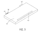
- Fig. 4 the holding profile 20 is shown together with another product carrier 40 '.
- This is a glass plate, which has on its rear end face a mold recess 43 for an adapter 50 '.
- the consumer 42 which is arranged on the underside of the glass plate. This consumer 42 is contacted via the electrical conductor tracks 53, 54.
- these conductor tracks 53, 54 are provided with contacts 55, 56 which, upon insertion of the goods carrier 40 'with its rear end edge into the holding profile 20, come into contact with the conductor tracks 33, 34 of the contact rail 30.
- the goods carriers 40, 40 ' can be plugged in at any desired location in the longitudinal direction 80 of the holding profile 20 and contact the printed conductors 33, 34 provided there.
- the holding profile 20 is better Fig. 5 to see.
- This holding profile 20 has a C-shaped receptacle 21 open in the front. In the opening 22 of the receptacle 21, goods carriers 40, 40 'or other goods carriers can be inserted.
- the retaining rail 20 is equipped with a contact rail 30. This is a cross-sectionally L-shaped plastic profile. On upright legs 31 of the contact rail 30, the conductor 33 via holding means 37, 37 'fixed and on the horizontal leg 32 holding means 38, 38 'are provided for the conductor 34, this is better Fig. 8c to see.
- the contact rail 30 is positively received in the retaining profile 20.
- the shape of the receptacle 21 is adapted in this area to the shape of the contact rail 30 in order to ensure a positive connection.
- the contact rail 30 can be inserted laterally into the retaining profile 20 for connection to the retaining profile 20.
- a support profile 70 is additionally provided in this example.
- the electrical power supply for the conductor tracks 33, 34 is realized via an end-side end piece 24.
- the arranged in the holding profile 20 contact rail 30 projects beyond the retaining section 20 end, so that it can be easily inserted into the end piece 24.
- corresponding contacts for the conductor tracks 33, 34 are provided.
- a grounding of the retaining profile 20 can be made.
- Other lines lead from the tail 24 to a corresponding power source.
- This power source then supplies the electrical energy to the conductor tracks 33, 34 and when the goods carrier 40 is inserted, as in FIG Fig. 1 As shown, the source-side contacts of the conductor tracks 53, 54 provided on the product carrier 40 come into contact with the conductor tracks 33, 34 provided on the holding profile 20, so that the connection to the consumer 42 is established.
- the source-side contacts 55, 56 of the provided on the product carrier 40 traces 53, 54 are housed in a contact housing 51 of the adapter 50.
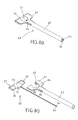
- the adapter 50 is arranged on the support arm 60. This connection is better from the Fig. 6a and Fig. 6b to see.
- the support arm 60 consists of a fixing part 61 and a cylindrical sleeve 62, which are interconnected. In the fastening part 61 a round mold recess 63 for the round contact housing 51 of the adapter 50 is present.
- two wings 64 are adjacent to the mold recess 63, 65 designed so that they cooperate for a positive connection with adjacent to the contact housing 51 provided supports 58, 59, as is apparent from Fig. 6a can be seen.
- the electrical conductor tracks 53, 54 are not received by the contact housing 51, which would be possible in another design of a contact housing.
- the electrical traces 53, 54 are received by the sleeve 62 of the support arm 60 and project end to end out of the sleeve 62 to, as from Fig. 2 can be seen when plugged support arm 60 in the recess 47 of the product carrier 40 to contact the consumer 42 at a corresponding contact point or contact surface.
- These consumer-side contact points of the interconnects 53, 54 can of course also be adapted accordingly to the contact points 42 present at the consumer in order to ensure a secure contact.
- Fig. 7a shows a further form of an adapter 50 '.
- an adapter 50 ' is provided when a goods carrier 40, 40' without support arms 60, 60 'to be fixed to the support section 20.
- the goods carrier 40 ' as in Fig. 4 shown, a corresponding mold recess 43 for the contact housing 51 'of the adapter 50'.
- the adapter can also be connected in other ways with the product carrier 40 '.
- this arrangement has the advantage that in the case of the goods carrier 40 'mounted on the holding profile 20, the adapter 50' is located within the receptacle 21.
- the conductor tracks 53, 54 of the adapter 50 ' are designed in this case as a foil line 52 and are fixed to the underside of the goods carrier 40' by an adhesive connection.
- Fig. 7b shows the adapter 50 'in a side view.
- the one contact 55 protrudes forward out of the contact housing 51 '
- the second contact 56 is provided on the underside of the contact housing 51'.
- the same arrangement is in the adapter 50 of Fig. 6a and Fig. 6b to find where the pin contact 55, the adapter housing 51 projects beyond the front.
- the second contact 56 on the underside of the adapter housing 51 is not to be seen here.
- the mechanical and electrical connection of the goods carrier 40, 40 'with the holding profile 20 is better from the Fig. 8a, 8b and 8c seen.
- the Fig. 8a shows again the holding profile 20, in this case as a cross section.
- the holding profile 20 has the front open receptacle 21 for the goods carrier 40, 40 '. These goods carriers 40, 40 'are inserted through the opening 22 in the receptacle 21.
- Adjacent to the opening 22 in the front region of the receptacle 21, an undercut longitudinal groove 23 for the support of the support profile 70 is provided.
- the rear portion of the receptacle 21 is designed so that the contact rail 30 can be received positively.
- For the vertical leg 31 of the contact rail 30, an upper groove 27 is provided for the vertical leg 31 of the contact rail 30, an upper groove 27 is provided.
- This leg 31 otherwise applies to the back 26 of the receptacle 21.
- the horizontal leg 32 of the contact rail 30 rests on the underside 28 of the receptacle 21 and is also received at its free end by a groove 29.
- a latching connection is provided, effected by a clamping lip 25 extending in the longitudinal direction 80 which is formed on the underside 28 of the receptacle 21 and engages in a longitudinal groove 39 on the underside of the contact rail 30.
- a product carrier 40 is inserted at any point in the longitudinal direction 80 through the opening 22.
- the insertion direction is the transverse direction 81. If the product carrier 40 is completely inserted, then the situation results, as shown in FIG Fig. 8b , The fastening part 61 of the support arm 60, which is connected to the goods carrier 40, is inserted into the receptacle 21 of the holding profile 20 and thus also the contact housing 51, which is received positively on the fastening part 61.
- FIG. 8b The fastening part 61 of the support arm 60, which is connected to the goods carrier 40, is inserted into the receptacle 21 of the holding profile 20 and thus also the contact housing 51, which is received positively on the fastening part 61.
- the conductor 33 extends in the longitudinal direction 80, the contacting can be made at any point in the longitudinal direction 80 of the holding profile 20.
- the conductor 33 is a metal band. By a nickel plating it is protected against corrosion.
- a faulty connection is likewise excluded, since here too the conductor track 34 provided on the holding profile 20 extends over the entire longitudinal extension of the holding profile 20 and the contact 56 has a sufficiently wide, substantially horizontally inserted adapter extending contact surface 36 offers.
- This conductor 34 is an S-shaped bent metal strip, wherein only the lower portion of the conductor 34 is held by means of holding means 38, 38 'on the contact rail 30 and thus on the holding profile 20.
- the upper portion of the conductor 34 is exposed and is thus designed to be resilient, with the inserted adapter 50, 50 ', the conductor 34 is pressed down, in a horizontal orientation. The then upwardly acting spring force causes a secure contact with the contact 56.
- the upper portion of the trace 34 is shown in a relaxed state to illustrate that the trace 34 can in each case reach the contact 56 for contacting.
- the inventive device for displaying goods 10 can be used for various applications.
- a particular advantage is the ease of use and safe installation. There is no need for specialized personnel for the construction of such a device 10 and changing the goods carrier 40, 40 'is easy by pulling out and pushing the Carrier 40, 40 'possible, this process is self-explanatory. Is a goods carrier 40, 40 'after installation the wrong way round, ie pushed with the bottom up in the holding section 20, no contact is made. The product carrier 40, 40 'can then be easily pulled out again and connected in the correct orientation with the holding profile 20. By using the low-current conductor tracks, the energy consumption for the consumers 42 of the product carriers 40, 40 'is low. By providing larger devices 10 with multiple lighting units on the product carriers 40, 40 'may even be saved energy for the ceiling lighting.
Abstract
Description
Die Erfindung betrifft eine Vorrichtung zum Tragen von Gegenständen, insbesondere von Waren zur Warenpräsentation, mit den Merkmalen des Oberbegriffs von Anspruch 1.The invention relates to a device for carrying objects, in particular goods for the presentation of goods, having the features of the preamble of claim 1.
Aus dem Stand der Technik sind verschiedenartige Vorrichtungen zur Warenpräsentation bekannt, bei denen an Wandelementen Konsolen, Tragarme und/oder Aufhänger von Waren gezeigt sind. Insbesondere für die Ladenausstattung und den Ladenbau sind Vorrichtungen gewünscht, die eine leichte Montage oder Demontage von Warenträgern an den entsprechenden Wandelementen, wie beispielsweise Halteprofilen, ermöglichen, um eine Anordnung zur Warenpräsentation bedarfsweise ändern zu können.Various devices for presenting goods are known from the prior art, in which on wall elements brackets, brackets and / or hangers of goods are shown. In particular, for the shop equipment and shop fitting devices are desired that allow easy mounting or dismounting of goods carriers on the corresponding wall elements, such as holding profiles, to be able to change an arrangement for displaying goods as needed.
In jüngster Zeit gibt es Bestrebungen die Funktion des Warenträgers zu erweitern. So sieht eine Vorrichtung gemäß
Eine verbesserte Vorrichtung zeigt das Gebrauchsmuster
Aufgabe der vorliegenden Erfindung ist es daher, eine Vorrichtung zum Tragen von Gegenständen, insbesondere von Waren zur Warenpräsentation, zur Verfügung zu stellen, die eine leichte Montage sowie Demontage der Warenträger ermöglicht und die Nachteile des Standes der Technik nicht aufweist.The object of the present invention is therefore to provide a device for carrying objects, in particular goods for the presentation of goods, which enables easy assembly and disassembly of the goods carriers and does not have the disadvantages of the prior art.
Diese Aufgabe wird mit einer Vorrichtung mit den Merkmalen des Anspruchs 1 erfüllt. Diese Vorrichtung besitzt ein an der Wand angeordnetes oder in einer Wand eingelassenes Halteprofil, wie beispielsweise ein stranggepresstes Aluminiumhohlprofil. Gehalten an diesem Halteprofil werden ein oder mehrere Warenträger, die zur Aufnahme, beispielweise zum Auflegen oder Aufhängen, von Waren dienen. Bei einem solchen Warenträger kann es sich beispielsweise um einen Tragboden aus unterschiedlichen Materialien oder eine Glasplatte handeln. Abwandlungen der Erfindung zur Anwendung bei einem Tragbügel, Tragarm oder anderen Formen von Warenträgern sind durch fachmännisches Handeln möglich. Der Warenträger wird über eine Steckverbindung in dem Halteprofil lösbar gehalten. Das Halteprofil weist hierfür eine in Längsrichtung des Profils verlaufende, nach außen offene U-förmige Aufnahme auf. Hier kann der Warenträger mit seiner hinteren Stirnseite bzw. mit am Warenträger vorgesehenen Tragarmen eingreifen. Der Warenträger besitzt zur Erweiterung seiner Funktionalität elektrische Verbraucher, beispielsweise Beleuchtungseinheiten, wie Lumineszenzdioden, Displays oder andere sonstige Kommunikationseinheiten, die über elektrische Schwachstrombahnen als Leiterbahnen mit der notwendigen Energie versorgt werden können.This object is achieved with a device having the features of claim 1. This device has a wall mounted or embedded in a wall holding profile, such as an extruded aluminum hollow profile. Held on this holding profile, one or more goods carriers, which are for receiving, for example, for hanging or hanging, to serve goods. In such a product carrier may be, for example, a support floor made of different materials or a glass plate. Modifications of the invention for use in a mounting bracket, arm or other forms of goods carriers are possible by expert action. The product carrier is releasably held in the retaining profile via a plug connection. For this purpose, the retaining profile has a U-shaped receptacle extending in the longitudinal direction of the profile and open towards the outside. Here, the goods carrier can intervene with its rear end or provided on the goods carrier support arms. The product carrier has to extend its functionality electrical consumers, such as lighting units, such as light-emitting diodes, displays or other other communication units that can be supplied via electrical low-current trains as tracks with the necessary energy.
Die Zufuhr elektrischer Energie erfolgt ausgehend von einer Stromquelle über Leiterbahnen im Halteprofil und über eine elektrische Verbindung zwischen den Leiterbahnen im Halteprofil mit den Leiterbahnen des Warenträgers bis hin zum Verbraucher. Die elektrische Verbindung wird beim Einstecken des Wartenträgers in die Aufnahme im Halteprofil geschlossen. Bei vorliegender Steckverbindung kontaktieren die elektrischen leitfähigen Kontaktstellen der am Warenträger vorgesehnen Leiterbahnen die Leiterbahnen im Halteprofil. Die hierfür notwendige Stromquelle kann am Halteprofil vorgesehen sein. In einem anderen Ausführungsbeispiel werden Leiterbahnen aus dem Halteprofil heraus zu einer Stromquelle geführt. In bevorzugter Weise erfolgt dies an den das Halteprofil endseitig verschließenden Endstücken.The supply of electrical energy takes place starting from a current source via conductor tracks in the holding profile and via an electrical connection between the conductor tracks in the holding profile with the conductor tracks of the goods carrier up to the consumer. The electrical connection is closed when inserting the waiting support in the recording in the holding profile. In the case of the present connector, the electrical conductive contact points of the conductor tracks provided on the goods carrier contact the conductor tracks in the retaining profile. The necessary power source can be provided on the retaining profile. In another embodiment, traces are guided out of the holding profile out to a power source. Preferably, this is done on the retaining profile end-closing end pieces.
Besonders vorteilhaft an der erfindungsgemäßen Vorrichtung ist die Ausgestaltung und Anordnung der Kontakte sowohl am Halteprofil als auch am Warenträger. So werden die Leiterbahnen im Halteprofil so angeordnet, dass eine Leiterbahn an der Rückwand des Halteprofils bzw. einer zur Rückwand parallel angeordneten Wand im Halteprofil vorgesehen ist und eine Leiterbahn an der Unterseite der Aufnahme im Halteprofil bzw. einer zur Unterseite parallel angeordneten Wand im Halteprofil angeordnet wird. Auf diese Weise haben die beiden im Halteprofil vorgesehenen Leiterbahnen eine senkrechte Ausrichtung zueinander. In gleicher Ausrichtung werden die quellenseitigen Kontaktstellen der Leiterbahnen des Warenträgers vorgesehen. Die elektrischen Leiterbahnen im Halteprofil können direkt mit dem Halteprofil verbunden sein, wenn das Halteprofil aus einem isolierenden Werkstoff besteht. Bei metallischen Halteprofilen wird vorzugsweise eine separate Kontaktschiene, beispielsweise eine extrudierte Kunstoffprofilschiene, vorgesehen, die mit den elektrischen Leiterbahnen bestückt wird. Diese Kontaktschiene ist vorzugsweise ein im Querschnitt L-förmiges Profil, wobei die beiden Schenkel des Kunststoffprofils senkrecht aufeinander stehen und Haltemittel für die Leiterbahnen besitzen. Eine Leiterbahn wird an dem aufrecht stehenden Schenkel angeordnet. Hierbei handelt es sich vorzugsweise um eine im Querschnitt rechteckige, in Längsrichtung des Halteprofils verlaufende Metallschiene bzw. um ein Metallband, wobei diese Leiterbahn über die gesamte Längsausdehnung des Halteprofils eine breite, sich vertikal erstreckende Kontaktfläche zur bedarfsweisen Kontaktierung bildet. Die andere im Wesentlichen horizontal verlaufende Leiterbahn wird an dem waagerechten Schenkel der Kontaktschiene festgelegt. Diese Leiterbahn ist vorzugsweise ein im Querschnitt S-förmiges Metallband, welches sich über die gesamte Längsausdehnung des Halteprofils erstreckt. Da dieses Metallband nur im unteren Bereich an der Kontaktschiene festgelegt ist, bildet der obere Bereich des Metallbandes eine Feder mit einer im Wesentlichen horizontal verlaufenden Kontaktfläche. Die so bestückte Kontaktschiene wird in der Aufnahme des Halteprofils formschlüssig aufgenommen, beispielweise seitlich in die Kontaktschiene eingeschoben. Ist die Kontaktschiene im Halteprofil angeordnet, weist das Halteprofil über seine gesamte Längsausdehnung Kontaktierungsmöglichkeiten auf, nämlich die vertikale bzw. horizontale Kontaktfläche der beiden Leiterbahnen. Die Ausgestaltung der Leiterbahnen und deren Anordnung im Halteprofil oder in der Kontaktschiene lässt sich auch auf andere Weisen realisieren. Wesentlich ist jedoch, dass sich am Halteprofil eine senkrecht angeordnete und eine weitere horizontal angeordnete, möglichst über die gesamte Längsausdehnung verlaufende Kontaktfläche ergibt.Particularly advantageous in the device according to the invention is the configuration and arrangement of the contacts both on the holding profile and on the goods carrier. Thus, the conductor tracks are arranged in the holding profile so that a conductor track is provided on the rear wall of the holding profile or a wall arranged parallel to the rear wall in the holding profile and a conductor track on the underside of the receptacle in the holding profile or arranged parallel to the bottom wall in the holding profile becomes. In this way the two provided in the holding profile traces have a vertical orientation to each other. In the same orientation, the source-side contact points of the conductor tracks of the goods carrier are provided. The electrical conductor tracks in the holding profile can be connected directly to the retaining profile, if the retaining profile consists of an insulating material. In the case of metallic holding profiles, a separate contact rail, for example an extruded plastic profile rail, is preferably provided, which is equipped with the electrical conductor tracks. This contact rail is preferably a cross-sectionally L-shaped profile, wherein the two legs of the plastic profile are perpendicular to each other and have holding means for the conductor tracks. A trace is placed on the upright leg. This is preferably a rectangular in cross-section, extending in the longitudinal direction of the holding profile metal rail or a metal strip, said conductor over the entire longitudinal extent of the holding profile forms a wide, vertically extending contact surface for on-demand contacting. The other substantially horizontally extending trace is fixed to the horizontal leg of the contact rail. This conductor track is preferably a cross-sectionally S-shaped metal strip, which extends over the entire longitudinal extent of the holding profile. Since this metal strip is fixed to the contact rail only in the lower region, the upper region of the metal strip forms a spring with a contact surface extending substantially horizontally. The so populated contact rail is positively received in the receptacle of the retaining profile, for example, laterally inserted into the contact rail. If the contact rail is arranged in the retaining profile, the retaining profile has contacting possibilities over its entire longitudinal extent, namely the vertical or horizontal contact surface of the two conductor tracks. The configuration of the strip conductors and their arrangement in the holding profile or in the contact rail can also be realized in other ways. It is essential, however, that results in a vertically arranged and a further horizontally disposed, possibly over the entire longitudinal extent extending contact surface on the holding profile.
Diese Kontaktflächen des Halteprofils gelangen mit den quellenseitigen Kontaktstellen der am Warenträger vorgesehenen Leiterbahnen in elektrische Verbindung, sobald der Warenträger in die Aufnahme am Halteprofil eingesteckt wird. Die für den Warenträger vorgesehenen Leiterbahnen besitzen verbraucherseitige Kontaktstellen für den Kontakt zum Verbraucher und an der Quellenseite kontaktieren die elektrisch leitfähigen Kontakte der Leiterbahnen die vorbeschriebenen Kontaktflächen der Leiterbahnen am Halteprofil. Die quellenseitigen Kontaktstellen der Leiterbahnen am Warenträger werden bevorzugt in einem Kontaktgehäuse eines Adapters aufgenommen, welches mit dem Warenträger verbunden ist. Um eine Kontaktierung der vorbeschriebenen Kontaktflächen der Leiterbahnen am Halteprofil zu ermöglichen, müssen diese Kontakte entsprechend ausgerichtet sein.These contact surfaces of the holding profile get into electrical connection with the source-side contact points of the conductor carriers provided on the product carrier as soon as the product carrier is inserted into the receptacle on the holding profile. The conductor tracks provided for the goods carrier have consumer-side contact points for the contact with the consumer and, at the source side, the electrically conductive contacts of the conductor tracks contact the above-described contact surfaces of the conductor tracks on the holding profile. The source-side contact points of the conductor tracks on the goods carrier are preferably accommodated in a contact housing of an adapter, which is connected to the goods carrier. In order to enable a contacting of the above-described contact surfaces of the conductor tracks on the holding profile, these contacts must be aligned accordingly.
Bei einer bevorzugten Ausführung wird ein quellenseitiger Kontakt als Stiftkontakt vorgesehen. Dieser wird in horizontaler Ausrichtung, also der Querrichtung zum Halteprofil, im Adapter angeordnet, so dass er beim Einstecken des Warenträgers gegen die vertikale Kontaktfläche prellt. Eine weitere quellenseitige Kontaktstelle ist in vertikaler Ausrichtung vorgesehen, d.h. kontaktiert in Senkrechtrichtung bezogen auf das Halteprofil. Dieser Kontakt kann beispielsweise ein federnd gelagerter Kontakt sein. Dieser Kontakt berührt bei eingestecktem Warenträger die horizontale Kontaktfläche der am Halteprofil vorgesehenen Leiterbahn.In a preferred embodiment, a source-side contact is provided as a pin contact. This is arranged in a horizontal orientation, ie the transverse direction to the holding profile in the adapter, so that it bounces when inserting the goods carrier against the vertical contact surface. Another source-side pad is provided in vertical alignment, i. contacted in vertical direction based on the holding profile. This contact may be, for example, a spring-mounted contact. When the product carrier is inserted, this contact touches the horizontal contact surface of the conductor track provided on the holding profile.
Zur Verbindung des Adapters mit dem Warenträger sind verschiedene Ausführungen möglich. Handelt es sich bei dem Warenträger beispielsweise um eine Glasplatte, so kann das Kontaktgehäuse des Adapters in einer Formausnehmung der Glasplatte formschlüssig aufgenommen werden. Eine solche Formausnehmung ist bevorzugt und der Einfachheit halber rund oder oval. Die aus dem Kontaktgehäuse austretenden Leiterbahnen können für eine solche Glasplatte als transparente Folienleitung ausgebildet sein, die auf den Warenträger, d.h. die Glasplatte, aufgeklebt wird. Diese Klebeverbindung kann an der Oberseite, an der Unterseite oder bei Verbundglasplatten zwischen den Glasplatten vorgesehen sein, wenn bei der Verbundglasplatte beispielsweise der Verbraucher in der Verbundglasplatte eingebettet ist.To connect the adapter with the goods carrier different versions are possible. If the goods carrier is, for example, a glass plate, then the contact housing of the adapter can be received in a form-fitting manner in a mold recess of the glass plate in a form-fitting manner. Such a mold cavity is preferred and round or oval for the sake of simplicity. The emerging from the contact housing conductor tracks may be formed for such a glass plate as a transparent film line, which is glued to the goods carrier, ie the glass plate. This adhesive joint can be at the top, at the bottom or in laminated glass between the Glass plates may be provided when, for example, the consumer is embedded in the laminated glass plate in the laminated glass plate.
Bei einer anderen Ausführungsform, wo der Warenträgers mittels Tragarmen am Halteprofil gehalten wird, kann die Formausnehmung für das Kontaktgehäuse des Adapters an einem Tragarm vorgesehen sein, so dass das Kontaktgehäuse des Adapters ebenfalls formschlüssig in dem Tragarm gehalten ist. Die aus dem Kontaktgehäuse herausführenden Leiternbahnen werden in einer Hülse des Tragarms geschützt aufgenommen. Diese Hülsen des Tragarms können an der Unter- oder Oberseite des Warenträgers angeordnet werden. Bevorzugt werden diese jedoch in zylindrischen Ausnehmungen, die von der hinteren Stirnseite des Warenträgers ausgehen, eingeführt. Eine dieser zylindrischen Ausnehmungen reicht bis zum Verbraucher, so dass die verbraucherseitigen Kontaktstellen der elektrischen Leiterbahnen beim Einsetzen des mit dem Adapter versehenden Tragarm den Verbraucher in dem Warenträger kontaktieren.In another embodiment, where the goods carrier is held by means of support arms on the holding profile, the mold recess for the contact housing of the adapter may be provided on a support arm, so that the contact housing of the adapter is also held in the support arm positively. The ladder tracks leading out of the contact housing are received protected in a sleeve of the support arm. These sleeves of the support arm can be arranged on the bottom or top of the product carrier. However, these are preferably introduced into cylindrical recesses which extend from the rear end side of the goods carrier. One of these cylindrical recesses extends to the consumer, so that the consumer-side contact points of the electrical conductor tracks contact the consumer in the goods carrier when inserting the adapter arm provided with the adapter.
Die erfindungsgemäße Vorrichtung ist einfach handhabbar und kann damit insbesondere im Ladenbau vorteilhaft Einsatz finden, da sowohl eine Montage als auch Demontage der Warenträger an den wandseitigen Halteprofilen je nach Bedarf vorgenommen werden kann, ohne dass hierfür Fachpersonal notwendig ist. Dies erleichtert einen schnellen Umbau, um neue Waren auch neu präsentieren zu können. Des Weiteren wird durch die verwendeten Niederstrombahnen als Leiterbahnen nur wenig elektrische Energie, beispielsweise zur Beleuchtung, verbraucht. Die mit den Adaptern bestückten Warenträger können in einfachster Weise an den Halteprofilen durch eine Steckverbindung eingeschoben werden. Es wird auch bei herstellungsbedingten Tolleranzen am Warenträger eine sichere Kontaktierung erzielt, da der an der Rückseite des Warenträgers herausragende Stiftkontakt beim Einstecken des Warenträgers gegen eine breite Kontaktfläche der am Halteprofil vorgesehenen Leiterbahn anstoßen kann und der zweite am Warenträger vorgesehene quellenseitige Kontakt sich auf die federnd im Halteprofil gelagerte Leiterbahn schiebt.The device according to the invention is easy to handle and can therefore be used advantageously particularly in shop fitting, since both assembly and disassembly of the goods carrier on the wall-side holding profiles can be made as needed, without the need specialist personnel is necessary. This facilitates a quick rebuild to be able to present new goods also new. Furthermore, only low electrical energy, for example for lighting, is consumed by the low-current paths used as conductor tracks. The equipped with the adapters goods carrier can be inserted in the simplest way to the holding profiles by a plug connection. It is also achieved in manufacturing tolerances on the goods carrier secure contact, since the protruding at the back of the product carrier pin contact when inserting the goods carrier against a wide contact surface provided on the holding profile conductor path and the second provided on the goods carrier source-side contact on the spring in the Holding profile stored conductor slides.
Weitere Vorteile der vorliegenden Erfindung ergeben sich aus den nachfolgenden Zeichnungen sowie der zugehörigen Beschreibung. Es zeigen:
- Fig. 1:
- eine erfindungsgemäße Vorrichtung im montierten Zustand,
- Fig. 2:
- eine erfindungsgemäße Vorrichtung vor der Montage,
- Fig. 3:
- ein Wandträger mit Tragarmen,
- Fig. 4:
- eine weitere erfindungsgemäße Vorrichtung vor der Montage,
- Fig. 5:
- eine perspektivischer Ansicht des Halteprofils,
- Fig. 6a:
- ein Tragarm mit montiertem Adapter,
- Fig. 6b:
- ein Tragarm und Adapter vor der Montage,
- Fig. 7a:
- eine Draufsicht auf einen weiteren Adapter,
- Fig. 7b:
- eine Seitenansicht des Adapters von
Fig. 7a , - Fig. 8a:
- ein Querschnitt des Halteprofils,
- Fig. 8b:
- das Halteprofil von
Fig. 8a mit eingesetzter Kontaktschiene und eingestecktem Warenträger, - Fig. 8c:
- ein Ausschnitt von
Fig. 8b .
- Fig. 1:
- a device according to the invention in the mounted state,
- Fig. 2:
- a device according to the invention before assembly,
- 3:
- a wall support with support arms,
- 4:
- another device according to the invention before assembly,
- Fig. 5:
- a perspective view of the retaining profile,
- 6a:
- a support arm with mounted adapter,
- Fig. 6b:
- a support arm and adapter before mounting,
- Fig. 7a:
- a top view of another adapter,
- Fig. 7b:
- a side view of the adapter of
Fig. 7a . - 8a:
- a cross section of the holding profile,
- 8b:
- the retaining profile of
Fig. 8a with inserted contact rail and inserted goods carrier, - 8c:
- a section of
Fig. 8b ,
Die
In
Die Warenträger 40, 40' können an beliebiger Stelle in Längsrichtung 80 des Halteprofils 20 eingesteckt werden und die dort vorgesehenen Leiterbahnen 33, 34 kontaktieren. Das Halteprofil 20 ist besser aus
Bei dem Halteprofil 20 wird die elektrische Energiezufuhr für die Leiterbahnen 33, 34 über ein endseitiges Endstück 24 realisiert. Die im Halteprofil 20 angeordnete Kontaktschiene 30 überragt dazu das Halteprofil 20 endseitig, so dass es leicht bis in das Endstück 24 eingeführt werden kann. In diesem Endstück 24 sind entsprechende Kontakte für die Leiterbahnen 33, 34 vorgesehen. Zusätzlich kann eine Erdung des Halteprofils 20 vorgenommen werden. Weitere Leitungen führen aus dem Endstück 24 zu einer entsprechenden Stromquelle. Diese Stromquelle liefert dann die elektrische Energie an die Leiterbahnen 33, 34 und bei eingeschobenen Warenträger 40, wie in
Die quellenseitigen Kontakte 55, 56 der am Warenträger 40 vorgesehenen Leiterbahnen 53, 54 sind in einem Kontaktgehäuse 51 des Adapters 50 untergebracht. Bei der Ausführungsform gemäß
Die mechanische und elektrische Verbindung des Warenträgers 40, 40' mit dem Halteprofil 20 wird besser aus den
In das mit der Kontaktschiene 30 bestückte Halteprofil 20 wird durch die Öffnung 22 ein Warenträger 40 an beliebiger Stelle in Längsrichtung 80 eingeschoben. Die Einschubrichtung ist die Querrichtung 81. Ist der Warenträger 40 vollständig eingeschoben, so ergibt sich die Situation, gezeigt in
Die erfindungsgemäße Vorrichtung zur Warenpräsentation 10 ist für verschiedene Anwendungsbereiche einsetzbar. Ein besonderer Vorteil ist die einfache Bedienung und die sichere Montage. Es wird kein Fachpersonal für den Aufbau einer solchen Vorrichtung 10 benötigt und das Wechseln der Warenträger 40, 40' ist leicht durch Herausziehen und Einschieben der Warenträger 40, 40' möglich, wobei dieser Vorgang selbsterklärend ist. Ist ein Warenträger 40, 40' nach der Montage falsch herum, d.h. mit der Unterseite nach oben in das Halteprofil 20 eingeschoben, wird kein Kontakt hergestellt. Der Warenträger 40, 40' kann dann einfach wieder herausgezogen werden und in der richtigen Ausrichtung mit dem Halteprofil 20 verbunden werden. Durch die Verwendung der Niederstromleiterbahnen ist der Energieverbrauch für die Verbraucher 42 der Warenträger 40, 40' gering. Bei Vorsehen größerer Vorrichtungen 10 mit mehreren Beleuchtungseinheiten an den Warenträgern 40, 40' kann möglicherweise sogar Energie für die Deckenbeleuchtung gespart werden.The inventive device for displaying
- 1010
- Vorrichtung zu WarenpräsentationDevice for presentation of goods
- 2020
- Halteprofilretaining profile
- 2121
- Aufnahmeadmission
- 2222
- Öffnungopening
- 2323
- Längsnutlongitudinal groove
- 2424
- Endstücktail
- 2525
- Klemmlippeclamping lip
- 2626
- Rückwandrear wall
- 2727
- Nutgroove
- 2828
- Unterseitebottom
- 2929
- Nutgroove
- 3030
- Kontaktschienecontact bar
- 3131
- Schenkelleg
- 3232
- Schenkelleg
- 33, 3433, 34
- Leiterbahnenconductor tracks
- 35, 3635, 36
- Kontaktflächecontact area
- 37, 37'37, 37 '
- Haltemittelholding means
- 38, 38'38, 38 '
- Haltemittelholding means
- 3939
- Längsnutlongitudinal groove
- 40, 40'40, 40 '
- Warenträgergoods carriers
- 4141
- Rückseiteback
- 4242
- Verbraucherconsumer
- 4343
- Formausnehmungshaped recess
- 4444
- Oberseitetop
- 4545
- Unterseitebottom
- 4646
- Rinnegutter
- 47. 47'47. 47 '
- zylindrische Ausnehmungcylindrical recess
- 50, 50'50, 50 '
- Adapteradapter
- 51, 51'51, 51 '
- KontaktgehäuseContact housing
- 5252
- Foliefoil
- 53, 5453, 54
- Leiterbahnenconductor tracks
- 5555
- Stiftkontaktpin contact
- 5656
- Kontaktstellecontact point
- 5757
- Stirnseitefront
- 5858
- Auflageedition
- 5959
- Auflageedition
- 60, 60'60, 60 '
- TragarmBeam
- 61, 61'61, 61 '
- Befestigungsteilattachment portion
- 6262
- Hülseshell
- 6363
- Formausnehmungshaped recess
- 64, 6564, 65
- Flügelwing
- 6666
- Ansatzapproach
- 7070
- Auflageprofilsupport profile
- 8080
- Längsrichtunglongitudinal direction
- 8181
- Querrichtungtransversely
- 8282
- Senkrechtrichtungperpendicular direction
Claims (15)
mit einem an oder in einer Wand angeordneten Halteprofil (20) und mit einem die Waren aufnehmenden Warenträger (40, 40'), vorzugsweise einem Tragboden,
wobei der Warenträger (40, 40') über eine Steckverbindung in dem Halteprofil (20) lösbar gehalten wird und das Halteprofil (20) hierfür eine in Längsrichtung (80) verlaufende, nach außen offene U-förmige Aufnahme (21) besitzt,
wobei das Halteprofil (20) mit elektrischen Leiterbahnen (33, 34) ausgestattet ist, die einerseits mit einer Stromquelle verbindbar sind und andererseits zur Stromabnahme kontaktierbar sind,
wobei der Warenträger (40, 40') mit mindestens einem elektrischen Verbraucher (42) und mit elektrisch leitfähigen Leiterbahnen (53, 54) ausgestattet ist, wobei die elektrisch leitfähigen Kontaktstellen der Leiterbahnen (53, 54) an der Verbraucherseite mit dem Verbraucher (42) sowie an der Quellenseite mit den elektrischen Leiterbahnen (33, 34) am Halteprofil (20) bei Vorliegen der Steckverbindung zwischen Warenträger (40, 40') und Halteprofil (20) kontaktierbar sind,
wobei die vorgesehenen Leiterbahnen (33, 34; 53, 54) elektrische Schwachstrombahnen sind
dadurch gekennzeichnet,
dass die quellenseitigen Kontaktstellen der Leiterbahnen (53, 54) in ihrer Kontaktierungsrichtung unterschiedlich ausgerichtet sind, nämlich in senkrecht zueinander stehende Richtungen weisen, wobei eine als Stiftkontakt (55) ausgebildete Kontaktstelle von der Rückseite (41) des Warenträgers (40) weg in horizontaler Ausrichtung, der Querrichtung (81), zum Halteprofil (20) und die andere Kontaktstelle (56) in vertikaler Ausrichtung, der Senkrechtrichtung (82), zeigt und
dass die Leiterbahnen (33, 34) im Halteprofil (20) in einer senkrecht zueinander ausgerichteten Anordnung vorgesehen sind.Device for carrying objects, in particular goods for presentation of goods,
with a holding profile (20) arranged on or in a wall and with a goods carrier (40, 40 ') receiving the goods, preferably a supporting floor,
wherein the product carrier (40, 40 ') via a plug connection in the holding profile (20) is releasably held and the retaining profile (20) for this purpose in the longitudinal direction (80) extending, outwardly open U-shaped receptacle (21) has,
wherein the retaining profile (20) is provided with electrical conductor tracks (33, 34) which are connectable on the one hand to a current source and on the other hand are contactable for current drain,
wherein the goods carrier (40, 40 ') is equipped with at least one electrical load (42) and with electrically conductive tracks (53, 54), wherein the electrically conductive contact points of the tracks (53, 54) on the consumer side with the consumer (42 ) and at the source side with the electrical conductor tracks (33, 34) on the holding profile (20) in the presence of the plug connection between the product carrier (40, 40 ') and holding profile (20) are contactable,
wherein the provided conductor tracks (33, 34; 53, 54) are low-voltage electrical paths
characterized,
that the source-side contact points of the conductor tracks (53, 54) are oriented differently in its contacting direction, namely in pointing perpendicular to each other to each other, with a pin contact (55) formed contact point of the back (41) of the goods carrier (40) away in a horizontal orientation, the transverse direction (81), the holding profile (20) and the other contact point (56) in vertical orientation, the vertical direction (82), and shows
in that the strip conductors (33, 34) are provided in the holding profile (20) in an arrangement oriented perpendicular to one another.
Applications Claiming Priority (1)
| Application Number | Priority Date | Filing Date | Title |
|---|---|---|---|
| DE200910040605 DE102009040605A1 (en) | 2009-09-08 | 2009-09-08 | Device for carrying objects |
Publications (2)
| Publication Number | Publication Date |
|---|---|
| EP2292120A1 true EP2292120A1 (en) | 2011-03-09 |
| EP2292120B1 EP2292120B1 (en) | 2014-03-12 |
Family
ID=43067080
Family Applications (1)
| Application Number | Title | Priority Date | Filing Date |
|---|---|---|---|
| EP20100009268 Active EP2292120B1 (en) | 2009-09-08 | 2010-09-07 | Device for carrying objects |
Country Status (3)
| Country | Link |
|---|---|
| EP (1) | EP2292120B1 (en) |
| DE (1) | DE102009040605A1 (en) |
| ES (1) | ES2469870T3 (en) |
Cited By (11)
| Publication number | Priority date | Publication date | Assignee | Title |
|---|---|---|---|---|
| DE202012008355U1 (en) | 2012-09-03 | 2012-10-24 | Visplay International Ag | Suspension device for the presentation of goods with a current-carrying profile rail and therein suspendable primary carrier |
| EP2752618A1 (en) * | 2013-01-03 | 2014-07-09 | DongGuan HengLong Fixture Manufacturing Company LTD | Illuminating device for showcase |
| GB2512810A (en) * | 2013-01-30 | 2014-10-15 | Artform Internat Ltd | Display panel and method of manufacture |
| US8979296B2 (en) | 2011-03-08 | 2015-03-17 | Dci Marketing, Inc. | Illuminated shelving |
| DE102017107118A1 (en) * | 2017-04-03 | 2018-10-04 | Michael Welle | Storage device |
| IT201800007461A1 (en) * | 2018-07-24 | 2018-10-24 | Kitchen complex. | |
| US10130196B2 (en) | 2014-08-07 | 2018-11-20 | Artform International Limited | Product display shelf, system and method |
| US10405674B2 (en) | 2016-03-23 | 2019-09-10 | Retail Space Solutions Llc | Low product indicator for self facing merchandiser and related methods |
| US10702076B2 (en) | 2016-01-18 | 2020-07-07 | Atlas Bolt & Screw Company Llc | Sensors, devices, adapters and mating structures for merchandisers and related methods |
| US10952548B2 (en) | 2016-10-18 | 2021-03-23 | Retail Space Solutions Llc | Illuminated merchandiser, retrofit kit and related methods |
| US11272795B2 (en) * | 2019-02-22 | 2022-03-15 | Carl Landgren | Storage system |
Families Citing this family (2)
| Publication number | Priority date | Publication date | Assignee | Title |
|---|---|---|---|---|
| DE102011005735A1 (en) * | 2011-02-18 | 2012-08-23 | Ligaproduction Gmbh & Co. Kg | System for display stand, stall or exhibition stand and for shop fitting or for use in office or personal household, comprises wall, floor or ceiling element, carrier material and coating covering carrier material |
| DE102014102349B4 (en) * | 2014-02-24 | 2019-02-21 | Wanzl Metallwarenfabrik Gesellschaft Mit Beschränkter Haftung | shelving |
Citations (10)
| Publication number | Priority date | Publication date | Assignee | Title |
|---|---|---|---|---|
| US3395378A (en) * | 1967-03-22 | 1968-07-30 | Gen Electric | Supporting and connecting hanger assembly for power utilization devices for plug-in type electrical busways |
| US3596226A (en) * | 1969-08-01 | 1971-07-27 | Jack A Meltzer | Electrical poer track and shoe |
| US4729742A (en) * | 1984-01-25 | 1988-03-08 | Matsushita Electric Works, Ltd. | Electric power distribution track |
| EP0683998A1 (en) * | 1994-05-26 | 1995-11-29 | Patrick Carlin | Exhibition or display device with means for both attachment and power supply of light sources |
| US6527565B1 (en) * | 2000-08-11 | 2003-03-04 | Robert L. Johns | Adjustable light display assembly |
| DE202008003360U1 (en) | 2008-02-23 | 2008-06-26 | Visplay International Ag | Suspension device for displaying goods with a profile rail and a primary carrier which can be suspended therein |
| EP1476048B1 (en) | 2002-02-23 | 2008-07-16 | Visplay International AG | Profiled rail and accessories used as a suspension device |
| DE102007020125A1 (en) | 2007-04-28 | 2008-10-30 | Dula-Werke Dustmann & Co Gmbh | Device for presentation for selling goods, particulraly garments, has good-carrier for support like carier plate, carrier arm or bar, holder for carrier like column and furniture or wall |
| DE102008045836A1 (en) * | 2008-09-05 | 2010-03-11 | Guido Schulte | Panel arrangement, has insertion bracket with two limiting bars, which define receiving area formed as thorough slot over entire length of functional rail and are arranged at parallel distance to each other |
| DE202008016956U1 (en) * | 2008-12-20 | 2010-05-27 | Serafini Besitz Gmbh & Co. Kg | Lighting element in shopfitting or presentation systems |
-
2009
- 2009-09-08 DE DE200910040605 patent/DE102009040605A1/en not_active Withdrawn
-
2010
- 2010-09-07 ES ES10009268.3T patent/ES2469870T3/en active Active
- 2010-09-07 EP EP20100009268 patent/EP2292120B1/en active Active
Patent Citations (10)
| Publication number | Priority date | Publication date | Assignee | Title |
|---|---|---|---|---|
| US3395378A (en) * | 1967-03-22 | 1968-07-30 | Gen Electric | Supporting and connecting hanger assembly for power utilization devices for plug-in type electrical busways |
| US3596226A (en) * | 1969-08-01 | 1971-07-27 | Jack A Meltzer | Electrical poer track and shoe |
| US4729742A (en) * | 1984-01-25 | 1988-03-08 | Matsushita Electric Works, Ltd. | Electric power distribution track |
| EP0683998A1 (en) * | 1994-05-26 | 1995-11-29 | Patrick Carlin | Exhibition or display device with means for both attachment and power supply of light sources |
| US6527565B1 (en) * | 2000-08-11 | 2003-03-04 | Robert L. Johns | Adjustable light display assembly |
| EP1476048B1 (en) | 2002-02-23 | 2008-07-16 | Visplay International AG | Profiled rail and accessories used as a suspension device |
| DE102007020125A1 (en) | 2007-04-28 | 2008-10-30 | Dula-Werke Dustmann & Co Gmbh | Device for presentation for selling goods, particulraly garments, has good-carrier for support like carier plate, carrier arm or bar, holder for carrier like column and furniture or wall |
| DE202008003360U1 (en) | 2008-02-23 | 2008-06-26 | Visplay International Ag | Suspension device for displaying goods with a profile rail and a primary carrier which can be suspended therein |
| DE102008045836A1 (en) * | 2008-09-05 | 2010-03-11 | Guido Schulte | Panel arrangement, has insertion bracket with two limiting bars, which define receiving area formed as thorough slot over entire length of functional rail and are arranged at parallel distance to each other |
| DE202008016956U1 (en) * | 2008-12-20 | 2010-05-27 | Serafini Besitz Gmbh & Co. Kg | Lighting element in shopfitting or presentation systems |
Cited By (18)
| Publication number | Priority date | Publication date | Assignee | Title |
|---|---|---|---|---|
| US8979296B2 (en) | 2011-03-08 | 2015-03-17 | Dci Marketing, Inc. | Illuminated shelving |
| US9775447B2 (en) | 2011-03-08 | 2017-10-03 | Dci Marketing, Inc. | Illuminated shelving |
| DE202012008355U1 (en) | 2012-09-03 | 2012-10-24 | Visplay International Ag | Suspension device for the presentation of goods with a current-carrying profile rail and therein suspendable primary carrier |
| WO2014032190A1 (en) | 2012-09-03 | 2014-03-06 | Visplay International Ag | Suspension device for presenting goods, having a current-carrying profiled rail and primary support which can be hung therein |
| EP2752618A1 (en) * | 2013-01-03 | 2014-07-09 | DongGuan HengLong Fixture Manufacturing Company LTD | Illuminating device for showcase |
| GB2512810A (en) * | 2013-01-30 | 2014-10-15 | Artform Internat Ltd | Display panel and method of manufacture |
| GB2512810B (en) * | 2013-01-30 | 2018-07-04 | Artform Int Ltd | Display panel and method of manufacture |
| US10470594B2 (en) | 2014-08-07 | 2019-11-12 | Artform International Limited | Product display shelf, system and method |
| US10130196B2 (en) | 2014-08-07 | 2018-11-20 | Artform International Limited | Product display shelf, system and method |
| US10702076B2 (en) | 2016-01-18 | 2020-07-07 | Atlas Bolt & Screw Company Llc | Sensors, devices, adapters and mating structures for merchandisers and related methods |
| US10405674B2 (en) | 2016-03-23 | 2019-09-10 | Retail Space Solutions Llc | Low product indicator for self facing merchandiser and related methods |
| US10588427B2 (en) | 2016-03-23 | 2020-03-17 | Retail Space Solutions Llc | Low product indicator for self facing merchandiser and related methods |
| US11291312B2 (en) | 2016-03-23 | 2022-04-05 | Retail Space Solutions Llc | Low product indicator for self facing merchandiser and related methods |
| US10952548B2 (en) | 2016-10-18 | 2021-03-23 | Retail Space Solutions Llc | Illuminated merchandiser, retrofit kit and related methods |
| EP3384809A1 (en) * | 2017-04-03 | 2018-10-10 | Michael Welle | Storage device |
| DE102017107118A1 (en) * | 2017-04-03 | 2018-10-04 | Michael Welle | Storage device |
| IT201800007461A1 (en) * | 2018-07-24 | 2018-10-24 | Kitchen complex. | |
| US11272795B2 (en) * | 2019-02-22 | 2022-03-15 | Carl Landgren | Storage system |
Also Published As
| Publication number | Publication date |
|---|---|
| DE102009040605A1 (en) | 2011-03-10 |
| ES2469870T3 (en) | 2014-06-20 |
| EP2292120B1 (en) | 2014-03-12 |
Similar Documents
| Publication | Publication Date | Title |
|---|---|---|
| EP2292120B1 (en) | Device for carrying objects | |
| EP2886021B1 (en) | Shelving system with electricity supply | |
| DE202011110536U1 (en) | Suspension device for displaying goods with a profile rail and a primary carrier which can be suspended therein | |
| EP0588894B1 (en) | Electrical installation consisting of individual structural units | |
| DE102005005422A1 (en) | Shelf with lighting device | |
| DE102018105699B4 (en) | Electrification system for hanging and / or shelving systems and hanging and / or shelving system with such electrification system | |
| EP1110489B1 (en) | Furniture system with modular lighting installation | |
| DE202016100561U1 (en) | Device for power and / or signal transmission to be arranged on a shelf, in particular a sales shelf customers | |
| WO2014177660A1 (en) | Rack system having lighting | |
| DE102015112035A1 (en) | Fastening device and shelving system for the presentation of goods | |
| DE102014019087A1 (en) | Rack construction for the presentation of goods with vertical mounting specific, electrifiable profile rails and suspended in the rails primary carriers | |
| DE102010036041B4 (en) | Electrifiable fastening system | |
| AT13533U1 (en) | uprights | |
| EP2344011B1 (en) | Lighting element in shopfitting or presentation systems | |
| DE102017100958B4 (en) | Electrification for hanging and/or shelving systems | |
| DE202008016956U1 (en) | Lighting element in shopfitting or presentation systems | |
| DE202008010414U1 (en) | Lighting element in shopfitting or presentation systems | |
| CH713509B1 (en) | Horizontal goods carrier, presentation module and goods presentation system. | |
| EP2106726B1 (en) | Shelf assembly | |
| DE202011103424U1 (en) | support wall | |
| DE202017104685U1 (en) | Device for power and / or signal transmission for on-shelf electronic pickup / pickup | |
| DE102016113272B4 (en) | Support for shelves with an adapter for power tapping | |
| DE202019106452U1 (en) | Furniture | |
| DE202014102579U1 (en) | Device for power supply to be arranged on a shelf power consumers | |
| DE102020103562A1 (en) | Perforated wall system |
Legal Events
| Date | Code | Title | Description |
|---|---|---|---|
| PUAI | Public reference made under article 153(3) epc to a published international application that has entered the european phase |
Free format text: ORIGINAL CODE: 0009012 |
|
| AK | Designated contracting states |
Kind code of ref document: A1 Designated state(s): AL AT BE BG CH CY CZ DE DK EE ES FI FR GB GR HR HU IE IS IT LI LT LU LV MC MK MT NL NO PL PT RO SE SI SK SM TR |
|
| AX | Request for extension of the european patent |
Extension state: BA ME RS |
|
| 17P | Request for examination filed |
Effective date: 20110222 |
|
| GRAP | Despatch of communication of intention to grant a patent |
Free format text: ORIGINAL CODE: EPIDOSNIGR1 |
|
| INTG | Intention to grant announced |
Effective date: 20131010 |
|
| GRAS | Grant fee paid |
Free format text: ORIGINAL CODE: EPIDOSNIGR3 |
|
| GRAA | (expected) grant |
Free format text: ORIGINAL CODE: 0009210 |
|
| AK | Designated contracting states |
Kind code of ref document: B1 Designated state(s): AL AT BE BG CH CY CZ DE DK EE ES FI FR GB GR HR HU IE IS IT LI LT LU LV MC MK MT NL NO PL PT RO SE SI SK SM TR |
|
| REG | Reference to a national code |
Ref country code: GB Ref legal event code: FG4D Free format text: NOT ENGLISH |
|
| REG | Reference to a national code |
Ref country code: CH Ref legal event code: EP Ref country code: CH Ref legal event code: NV Representative=s name: ISLER AND PEDRAZZINI AG, CH |
|
| REG | Reference to a national code |
Ref country code: AT Ref legal event code: REF Ref document number: 655651 Country of ref document: AT Kind code of ref document: T Effective date: 20140315 |
|
| REG | Reference to a national code |
Ref country code: IE Ref legal event code: FG4D Free format text: LANGUAGE OF EP DOCUMENT: GERMAN |
|
| REG | Reference to a national code |
Ref country code: DE Ref legal event code: R096 Ref document number: 502010006328 Country of ref document: DE Effective date: 20140417 |
|
| REG | Reference to a national code |
Ref country code: ES Ref legal event code: FG2A Ref document number: 2469870 Country of ref document: ES Kind code of ref document: T3 Effective date: 20140620 |
|
| REG | Reference to a national code |
Ref country code: NL Ref legal event code: VDEP Effective date: 20140312 |
|
| PG25 | Lapsed in a contracting state [announced via postgrant information from national office to epo] |
Ref country code: LT Free format text: LAPSE BECAUSE OF FAILURE TO SUBMIT A TRANSLATION OF THE DESCRIPTION OR TO PAY THE FEE WITHIN THE PRESCRIBED TIME-LIMIT Effective date: 20140312 Ref country code: NO Free format text: LAPSE BECAUSE OF FAILURE TO SUBMIT A TRANSLATION OF THE DESCRIPTION OR TO PAY THE FEE WITHIN THE PRESCRIBED TIME-LIMIT Effective date: 20140612 |
|
| REG | Reference to a national code |
Ref country code: LT Ref legal event code: MG4D |
|
| PG25 | Lapsed in a contracting state [announced via postgrant information from national office to epo] |
Ref country code: FI Free format text: LAPSE BECAUSE OF FAILURE TO SUBMIT A TRANSLATION OF THE DESCRIPTION OR TO PAY THE FEE WITHIN THE PRESCRIBED TIME-LIMIT Effective date: 20140312 Ref country code: SE Free format text: LAPSE BECAUSE OF FAILURE TO SUBMIT A TRANSLATION OF THE DESCRIPTION OR TO PAY THE FEE WITHIN THE PRESCRIBED TIME-LIMIT Effective date: 20140312 Ref country code: CY Free format text: LAPSE BECAUSE OF FAILURE TO SUBMIT A TRANSLATION OF THE DESCRIPTION OR TO PAY THE FEE WITHIN THE PRESCRIBED TIME-LIMIT Effective date: 20140312 |
|
| PG25 | Lapsed in a contracting state [announced via postgrant information from national office to epo] |
Ref country code: HR Free format text: LAPSE BECAUSE OF FAILURE TO SUBMIT A TRANSLATION OF THE DESCRIPTION OR TO PAY THE FEE WITHIN THE PRESCRIBED TIME-LIMIT Effective date: 20140312 Ref country code: LV Free format text: LAPSE BECAUSE OF FAILURE TO SUBMIT A TRANSLATION OF THE DESCRIPTION OR TO PAY THE FEE WITHIN THE PRESCRIBED TIME-LIMIT Effective date: 20140312 |
|
| PG25 | Lapsed in a contracting state [announced via postgrant information from national office to epo] |
Ref country code: RO Free format text: LAPSE BECAUSE OF FAILURE TO SUBMIT A TRANSLATION OF THE DESCRIPTION OR TO PAY THE FEE WITHIN THE PRESCRIBED TIME-LIMIT Effective date: 20140312 Ref country code: CZ Free format text: LAPSE BECAUSE OF FAILURE TO SUBMIT A TRANSLATION OF THE DESCRIPTION OR TO PAY THE FEE WITHIN THE PRESCRIBED TIME-LIMIT Effective date: 20140312 Ref country code: NL Free format text: LAPSE BECAUSE OF FAILURE TO SUBMIT A TRANSLATION OF THE DESCRIPTION OR TO PAY THE FEE WITHIN THE PRESCRIBED TIME-LIMIT Effective date: 20140312 Ref country code: IS Free format text: LAPSE BECAUSE OF FAILURE TO SUBMIT A TRANSLATION OF THE DESCRIPTION OR TO PAY THE FEE WITHIN THE PRESCRIBED TIME-LIMIT Effective date: 20140712 Ref country code: BG Free format text: LAPSE BECAUSE OF FAILURE TO SUBMIT A TRANSLATION OF THE DESCRIPTION OR TO PAY THE FEE WITHIN THE PRESCRIBED TIME-LIMIT Effective date: 20140612 Ref country code: EE Free format text: LAPSE BECAUSE OF FAILURE TO SUBMIT A TRANSLATION OF THE DESCRIPTION OR TO PAY THE FEE WITHIN THE PRESCRIBED TIME-LIMIT Effective date: 20140312 |
|
| PG25 | Lapsed in a contracting state [announced via postgrant information from national office to epo] |
Ref country code: SK Free format text: LAPSE BECAUSE OF FAILURE TO SUBMIT A TRANSLATION OF THE DESCRIPTION OR TO PAY THE FEE WITHIN THE PRESCRIBED TIME-LIMIT Effective date: 20140312 Ref country code: PL Free format text: LAPSE BECAUSE OF FAILURE TO SUBMIT A TRANSLATION OF THE DESCRIPTION OR TO PAY THE FEE WITHIN THE PRESCRIBED TIME-LIMIT Effective date: 20140312 |
|
| REG | Reference to a national code |
Ref country code: DE Ref legal event code: R097 Ref document number: 502010006328 Country of ref document: DE |
|
| PG25 | Lapsed in a contracting state [announced via postgrant information from national office to epo] |
Ref country code: PT Free format text: LAPSE BECAUSE OF FAILURE TO SUBMIT A TRANSLATION OF THE DESCRIPTION OR TO PAY THE FEE WITHIN THE PRESCRIBED TIME-LIMIT Effective date: 20140714 |
|
| PLBE | No opposition filed within time limit |
Free format text: ORIGINAL CODE: 0009261 |
|
| STAA | Information on the status of an ep patent application or granted ep patent |
Free format text: STATUS: NO OPPOSITION FILED WITHIN TIME LIMIT |
|
| PG25 | Lapsed in a contracting state [announced via postgrant information from national office to epo] |
Ref country code: DK Free format text: LAPSE BECAUSE OF FAILURE TO SUBMIT A TRANSLATION OF THE DESCRIPTION OR TO PAY THE FEE WITHIN THE PRESCRIBED TIME-LIMIT Effective date: 20140312 |
|
| 26N | No opposition filed |
Effective date: 20141215 |
|
| REG | Reference to a national code |
Ref country code: DE Ref legal event code: R097 Ref document number: 502010006328 Country of ref document: DE Effective date: 20141215 |
|
| PG25 | Lapsed in a contracting state [announced via postgrant information from national office to epo] |
Ref country code: IT Free format text: LAPSE BECAUSE OF FAILURE TO SUBMIT A TRANSLATION OF THE DESCRIPTION OR TO PAY THE FEE WITHIN THE PRESCRIBED TIME-LIMIT Effective date: 20140312 |
|
| REG | Reference to a national code |
Ref country code: CH Ref legal event code: PCOW Free format text: NEW ADDRESS: KARLSBADER STRASSE 1A, 44225 DORTMUND (DE) |
|
| PG25 | Lapsed in a contracting state [announced via postgrant information from national office to epo] |
Ref country code: LU Free format text: LAPSE BECAUSE OF FAILURE TO SUBMIT A TRANSLATION OF THE DESCRIPTION OR TO PAY THE FEE WITHIN THE PRESCRIBED TIME-LIMIT Effective date: 20140907 Ref country code: MC Free format text: LAPSE BECAUSE OF FAILURE TO SUBMIT A TRANSLATION OF THE DESCRIPTION OR TO PAY THE FEE WITHIN THE PRESCRIBED TIME-LIMIT Effective date: 20140312 |
|
| REG | Reference to a national code |
Ref country code: IE Ref legal event code: MM4A |
|
| PG25 | Lapsed in a contracting state [announced via postgrant information from national office to epo] |
Ref country code: BE Free format text: LAPSE BECAUSE OF NON-PAYMENT OF DUE FEES Effective date: 20140930 |
|
| REG | Reference to a national code |
Ref country code: FR Ref legal event code: CA Effective date: 20150623 |
|
| PG25 | Lapsed in a contracting state [announced via postgrant information from national office to epo] |
Ref country code: SI Free format text: LAPSE BECAUSE OF FAILURE TO SUBMIT A TRANSLATION OF THE DESCRIPTION OR TO PAY THE FEE WITHIN THE PRESCRIBED TIME-LIMIT Effective date: 20140312 |
|
| PG25 | Lapsed in a contracting state [announced via postgrant information from national office to epo] |
Ref country code: IE Free format text: LAPSE BECAUSE OF NON-PAYMENT OF DUE FEES Effective date: 20140907 |
|
| REG | Reference to a national code |
Ref country code: FR Ref legal event code: PLFP Year of fee payment: 6 |
|
| PG25 | Lapsed in a contracting state [announced via postgrant information from national office to epo] |
Ref country code: SM Free format text: LAPSE BECAUSE OF FAILURE TO SUBMIT A TRANSLATION OF THE DESCRIPTION OR TO PAY THE FEE WITHIN THE PRESCRIBED TIME-LIMIT Effective date: 20140312 |
|
| PG25 | Lapsed in a contracting state [announced via postgrant information from national office to epo] |
Ref country code: MT Free format text: LAPSE BECAUSE OF FAILURE TO SUBMIT A TRANSLATION OF THE DESCRIPTION OR TO PAY THE FEE WITHIN THE PRESCRIBED TIME-LIMIT Effective date: 20140312 Ref country code: GR Free format text: LAPSE BECAUSE OF FAILURE TO SUBMIT A TRANSLATION OF THE DESCRIPTION OR TO PAY THE FEE WITHIN THE PRESCRIBED TIME-LIMIT Effective date: 20140613 |
|
| PG25 | Lapsed in a contracting state [announced via postgrant information from national office to epo] |
Ref country code: TR Free format text: LAPSE BECAUSE OF FAILURE TO SUBMIT A TRANSLATION OF THE DESCRIPTION OR TO PAY THE FEE WITHIN THE PRESCRIBED TIME-LIMIT Effective date: 20140312 Ref country code: HU Free format text: LAPSE BECAUSE OF FAILURE TO SUBMIT A TRANSLATION OF THE DESCRIPTION OR TO PAY THE FEE WITHIN THE PRESCRIBED TIME-LIMIT; INVALID AB INITIO Effective date: 20100907 |
|
| REG | Reference to a national code |
Ref country code: FR Ref legal event code: PLFP Year of fee payment: 7 |
|
| REG | Reference to a national code |
Ref country code: AT Ref legal event code: MM01 Ref document number: 655651 Country of ref document: AT Kind code of ref document: T Effective date: 20150907 |
|
| PG25 | Lapsed in a contracting state [announced via postgrant information from national office to epo] |
Ref country code: AT Free format text: LAPSE BECAUSE OF NON-PAYMENT OF DUE FEES Effective date: 20150907 |
|
| REG | Reference to a national code |
Ref country code: FR Ref legal event code: PLFP Year of fee payment: 8 |
|
| PG25 | Lapsed in a contracting state [announced via postgrant information from national office to epo] |
Ref country code: MK Free format text: LAPSE BECAUSE OF FAILURE TO SUBMIT A TRANSLATION OF THE DESCRIPTION OR TO PAY THE FEE WITHIN THE PRESCRIBED TIME-LIMIT Effective date: 20140312 |
|
| REG | Reference to a national code |
Ref country code: FR Ref legal event code: PLFP Year of fee payment: 9 |
|
| PG25 | Lapsed in a contracting state [announced via postgrant information from national office to epo] |
Ref country code: AL Free format text: LAPSE BECAUSE OF FAILURE TO SUBMIT A TRANSLATION OF THE DESCRIPTION OR TO PAY THE FEE WITHIN THE PRESCRIBED TIME-LIMIT Effective date: 20140312 |
|
| PGFP | Annual fee paid to national office [announced via postgrant information from national office to epo] |
Ref country code: GB Payment date: 20230920 Year of fee payment: 14 |
|
| PGFP | Annual fee paid to national office [announced via postgrant information from national office to epo] |
Ref country code: FR Payment date: 20230922 Year of fee payment: 14 Ref country code: DE Payment date: 20230830 Year of fee payment: 14 |
|
| PGFP | Annual fee paid to national office [announced via postgrant information from national office to epo] |
Ref country code: ES Payment date: 20231002 Year of fee payment: 14 |
|
| PGFP | Annual fee paid to national office [announced via postgrant information from national office to epo] |
Ref country code: CH Payment date: 20231001 Year of fee payment: 14 |