EP2291005A2 - Multichannel cochlea implant having neural telemetry reaction - Google Patents
Multichannel cochlea implant having neural telemetry reaction Download PDFInfo
- Publication number
- EP2291005A2 EP2291005A2 EP10075535A EP10075535A EP2291005A2 EP 2291005 A2 EP2291005 A2 EP 2291005A2 EP 10075535 A EP10075535 A EP 10075535A EP 10075535 A EP10075535 A EP 10075535A EP 2291005 A2 EP2291005 A2 EP 2291005A2
- Authority
- EP
- European Patent Office
- Prior art keywords
- data
- coupled
- bit
- signal
- input signal
- Prior art date
- Legal status (The legal status is an assumption and is not a legal conclusion. Google has not performed a legal analysis and makes no representation as to the accuracy of the status listed.)
- Granted
Links
Images


Classifications
-
- H—ELECTRICITY
- H04—ELECTRIC COMMUNICATION TECHNIQUE
- H04R—LOUDSPEAKERS, MICROPHONES, GRAMOPHONE PICK-UPS OR LIKE ACOUSTIC ELECTROMECHANICAL TRANSDUCERS; DEAF-AID SETS; PUBLIC ADDRESS SYSTEMS
- H04R25/00—Deaf-aid sets, i.e. electro-acoustic or electro-mechanical hearing aids; Electric tinnitus maskers providing an auditory perception
- H04R25/60—Mounting or interconnection of hearing aid parts, e.g. inside tips, housings or to ossicles
- H04R25/604—Mounting or interconnection of hearing aid parts, e.g. inside tips, housings or to ossicles of acoustic or vibrational transducers
- H04R25/606—Mounting or interconnection of hearing aid parts, e.g. inside tips, housings or to ossicles of acoustic or vibrational transducers acting directly on the eardrum, the ossicles or the skull, e.g. mastoid, tooth, maxillary or mandibular bone, or mechanically stimulating the cochlea, e.g. at the oval window
-
- A—HUMAN NECESSITIES
- A61—MEDICAL OR VETERINARY SCIENCE; HYGIENE
- A61N—ELECTROTHERAPY; MAGNETOTHERAPY; RADIATION THERAPY; ULTRASOUND THERAPY
- A61N1/00—Electrotherapy; Circuits therefor
- A61N1/18—Applying electric currents by contact electrodes
- A61N1/32—Applying electric currents by contact electrodes alternating or intermittent currents
- A61N1/36—Applying electric currents by contact electrodes alternating or intermittent currents for stimulation
- A61N1/36036—Applying electric currents by contact electrodes alternating or intermittent currents for stimulation of the outer, middle or inner ear
- A61N1/36038—Cochlear stimulation
-
- A—HUMAN NECESSITIES
- A61—MEDICAL OR VETERINARY SCIENCE; HYGIENE
- A61N—ELECTROTHERAPY; MAGNETOTHERAPY; RADIATION THERAPY; ULTRASOUND THERAPY
- A61N1/00—Electrotherapy; Circuits therefor
- A61N1/18—Applying electric currents by contact electrodes
- A61N1/32—Applying electric currents by contact electrodes alternating or intermittent currents
- A61N1/36—Applying electric currents by contact electrodes alternating or intermittent currents for stimulation
- A61N1/372—Arrangements in connection with the implantation of stimulators
- A61N1/37211—Means for communicating with stimulators
- A61N1/37252—Details of algorithms or data aspects of communication system, e.g. handshaking, transmitting specific data or segmenting data
-
- H—ELECTRICITY
- H04—ELECTRIC COMMUNICATION TECHNIQUE
- H04R—LOUDSPEAKERS, MICROPHONES, GRAMOPHONE PICK-UPS OR LIKE ACOUSTIC ELECTROMECHANICAL TRANSDUCERS; DEAF-AID SETS; PUBLIC ADDRESS SYSTEMS
- H04R25/00—Deaf-aid sets, i.e. electro-acoustic or electro-mechanical hearing aids; Electric tinnitus maskers providing an auditory perception
- H04R25/50—Customised settings for obtaining desired overall acoustical characteristics
- H04R25/505—Customised settings for obtaining desired overall acoustical characteristics using digital signal processing
Definitions
- the present invention relates to bit format systems for functional electrical stimulation, and more particularly, to systems for electrostimulation of the acoustic nerve.
- Cochlear implants are a means to help profoundly deaf or severely hearing impaired persons. Unlike conventional hearing aids, which just apply an amplified and modified sound signal, a cochlear implant is based on direct electrical stimulation of the acoustic nerve. The intention of a cochlear implant is to stimulate nervous structures in the inner ear electrically in such a way that hearing impressions most similar to normal hearing are obtained.
- a cochlear prosthesis essentially consists of two parts, the speech processor and the implanted stimulator.
- the speech processor contains the power supply (batteries) of the overall system and is used to perform signal processing of the acoustic signal to extract the stimulation parameters.
- the stimulator (implant) generates the stimulation patterns and conducts them to the nervous tissue by means of an electrode array which usually is positioned in the scala tympani in the inner ear.
- the connection between the speech processor and the implanted receiver can be established by means of encoding digital information in an rf-channel involving an inductively coupled coils system.
- Decoding the information within the implant can require envelope detection.
- Envelope detection of an RF signal within an implant is usually performed with a simple circuit, as shown in Figure 1 , composed of a rectifier diode 4, an RC-network 1 and 2, and a comparator 7.
- a drawback to this circuit is that the total power consumption of the RC-network, due in part to the ohmic resistor, can be considerable when taking into account the cochlear implant application.
- CIS Continuous Interleaved Sampling
- CIS symmetrical biphasic current pulses are used, which are strictly non-overlapping in time.
- the rate per channel typically is higher than 800pulses / sec
- Stimulation strategies based on simultaneous activation of electrode currents so far have not shown any advantage as compared to CIS.
- the basic problem is the spatial channel interaction caused by conductive tissue in the scala tympani between the stimulation electrodes. If two or more stimulation current sources are activated simultaneously, and if there is no correlation between them, the currents will flow between the active electrodes and do not reach the regions of neurons which are intended to be stimulated.
- the problem might get less severe with new stimulation electrode designs, where the electrodes are much closer to the modiolus as compared to existing electrodes, as described by Kuzma J., "Evaluation of new modiolus-hugging electrode concepts in a transparent model of the cochlea," proc. 4th European Symp. on Pediatric Cochlear Implantation, 's-Hertogenbosch, The Netherlands (June 1998 ), which is incorporated herein by reference.
- MCL and THL For stimulation, only amplitudes between MCL and THL (for each channel) are used.
- the dynamic range between MCL and THL typically is between 6-12dB.
- the absolute positions of MCLs and THLs vary considerably between patients, and differences can reach up to 40dB.
- the overall dynamic range for stimulation in currently used implants typically is about 60dB.
- MCLs and THLs are estimated during the fitting procedure by applying stimulation pulses and asking the patient about his/her subjective impression.
- This method usually works without problems with postlingually deaf patients.
- problems occur with prelingually or congenitally deaf patients, and in this group all ages - from small children to adults - are concerned.
- These patients are usually neither able to interpret nor to describe hearing impressions, and only rough estimations of MCLs and THLs based on behavioral methods are possible.
- An adequate acoustic input is extremely important for the infant's speech and hearing development, and this input in many cases can be provided with a properly fitted cochlear implant.
- EAPs Electrode evoked Action Potentials
- Gantz B., Brown C.J., Abbas P.J. "Intraoperative Measures of Electrically Evoked Auditory Nerve Compound Action Potentials," American Journal of Otology 15 (2):137-144 (1994 ), which is incorporated herein by reference.
- the overall response of the acoustic nerve to an electrical stimulus is measured very close to the position of nerve excitation.
- This neural response is caused by the superposition of single neural responses at the outside of the axon membranes.
- the amplitude of the EAP at the measurement position is between 10 ⁇ V and 1000 ⁇ V.
- Information about MCL and THL at a particular electrode position can first of all be expected from the so called "amplitude growth function," as described by Brown C. J., Abbas P. J., Borland J., Bertschy M. R., "Electrically evoked whole nerve action potentials in Ineraid cochlear implant users: responses to different stimulating electrode configurations and comparison to psychophysical responses," Journal of Speech and Hearing Research, vol. 39:453-467 (June 1996 ), which is incorporated herein by reference.
- This function is the relation between the amplitude of the stimulation pulse and the peak-to-peak voltage of the EAP.
- Another interesting relation is the so called “recovery function”.
- stimulation is achieved with two pulses with varying interpulse-interval.
- the recovery function as the relation of the amplitude of the 2nd EAP and the interpulse-interval allows one to draw conclusions about the refractory properties and particular properties concerning the time resolution of the acoustic nerve.
- a data transmission system having a coding unit coupled to a communications channel, that transmits encoded digital information having defined minimum and maximum durations of logical states "low” and "high".
- a decoding unit is coupled to the communication channel, which receives and decodes the information.
- the decoder is comprised of a free running local oscillator LO coupled to an array of sampling capacitors, that effectively sample the information using the LO frequency.
- a circuit is coupled to the sampling capacitors, that decodes the information and corrects any mismatch between nominal and actual LO frequency.
- the encoded digitial information is contained in an RF signal.
- the data transmission system can be used in a cochlear implant system or an implantable system for functional electrostimulation.
- a data decoder system coupled to a communication channel that decodes information received.
- the decoder has a free running local oscillator LO coupled to an array of sampling capacitors, that effectively sample the information using the LO frequency.
- a circuit is coupled to the sampling capacitors, that decodes the information and corrects any mismatch between the nominal and actual LO frequency.
- the encoded digital information can be contained in an RF signal.
- the data decoder system can be used in a cochlear implant system, or a implantable system for functional electrostimulation.
- a circuit for detecting the envelope of an input signal comprising a first sampling capacitor C1 and a second sampling capacitor C2, both capacitors coupled to ground.
- a first switching matrix S1 cyclically couples C1 to an input signal via a rectifier diode, the input signal being encoded with digital data; a first input of a comparator; and ground.
- a second switch matrix S2 cyclically couples C2 to the input signal via the rectifier diode; the first input of the comparator, and ground.
- a local oscillator is coupled to S1 and S2, that controls switch matrices S1 and S2, the local oscillator having period T.
- a dc-reference is coupled to a second input of the comparator.
- a flip flop is coupled to the comparator output, the flip flop being clocked by the local oscillator producing a data bit stream output indicative of the input signal's envelope
- the circuit may be used for detecting the envelope of an input signal in a cochlear implant, wherein the input signal is an RF signal encoded with digital information.
- a first logical state is encoded in the input signal by the sequence "RF-carrier off” followed by "RF-carrier on”
- a second logical zero is encoded by the sequence "RF-carrier on” followed by "RF-carrier off.”
- the RF input signal may be encoded using Amplitude Shift Keying Modulation, the digital data employing a self-clocking bit format.
- C1 and C2 are sequentially and cyclically coupled via the switching matrices to the input signal via the rectifier diode for time duration T/2 (phase D), the comparator for time duration T (phase C), and ground for time duration T/2 (phase G).
- S2's switching sequence is offset from S1's switching sequence by a phase shift of T.
- the clock of the flip flop may be activated at the end of phases C on the negative slope of the local oscillator.
- a method for data telemetry where digital data is encoded into an input signal.
- the input signal is applied via a rectifier diode to a first switch matrix S1 and a second switch matrix S2, with S1 being coupled to a first sampling capacitor C1 and S2 being coupled to a second sampling capacitor C2.
- a local oscillator signal with period T is applied that controls S1 and S2, so as to cyclically couple C1 and C2 to the RF signal, a first input to a comparator, and ground.
- the comparator compares the first input to a DC reference voltage.
- the output of the comparator is then sampled via a flip flop clocked by the local oscillator, with the flip flop outputting a data bit stream representative of the envelope of the input signal having encoded information.
- the data telemetry method detects the envelope of an input signal in a cochlear implant, the input signal is an RF encoded signal encoded with digital data.
- a first logical state may be encoded in the input signal by the sequence "RF-carrier off” followed by "RF-carrier on,” and a second logical state is encoded by the sequence "RF-carrier on” followed by "RF-carrier off.”
- the input signal can contain special bit formats, such that the signal can be switched on or off for longer durations, such as 3B/2, B being the bit duration.
- the RF signal is encoded using Amplitude Shift Keying Modulation, the digital data employing a self-clocking bit format.
- sampling capacitors C1 and C2 are sequentially and cyclically coupled via the switching matrices to the input signal for time duration T/2 (phase D), the 1st input of the comparator for time duration T (phase C), and to ground for time duration T/2 (phase G), with S2's switching sequence being offset from S1's switching sequence by a phase shift of T.
- the clock of the flip flop is activated at the end of phases C on the negative slope of the local oscillator.
- the data bit stream is decoded, including distinguishing four different data bit stream states, a "short low” L1 defined by a data bit stream pattern of 0 or 00, a "short high” H1 defined by a data bit stream pattern of 11 or 111, a "long low” L2 defined by a data bit stream pattern of 000 or 000, and a "long high” H2 defined by a data bit stream pattern of 1111 or 11111.
- Two additional bit states may be distinguished, an "extra long low” L3 defined by a data bit stream pattern of 00000 or 000000, and an "extra long high” H3 defined by a data bit stream pattern of 111111 or 1111111.
- Triplet sequences may also be distinguishable, a triplet sequence having a starting short state L1 or H1, followed by a sequence of strictly alternating states L3 or H3, and a terminating short state L1 or H1.
- the triplet sequence can be used for control and synchronization.
- data telemetry is achieved by data word formats having a starting triplet sequence, followed by a particular number of information bits with self-clocking format; and a terminating triplet sequence. These data word formats can allow allow high rate stimulation strategies based on sign-correlated, simultaneous stimulation pulses.
- the encoded information allows stimulation with sign-correlated biphasic, symmetrical pulses, stimulation with sign-correlated triphasic, symmetrical pulses, and stimulation with sign-correlated triphasic pulses.
- a method of employing high-rate pulsatile stimulation receives encoded information, decodes the information, and applies stimulation modes based on the decoded information.
- the stimulaton modes comprising sign-correlated biphasic, symmetrical pulses, sign-correlated triphasic, symmetrical pulses, and sign-correlated triphasic pulses.
- a circuit and method for generating sign-correlated simultaneous pulsatile stimuli in a cochlear implant simultaneously applying current of same sign to a plurality of electrodes Ei A remote ground is switched to either Vdd or ground, creating a current in the remote ground electrode equal to the sum of all single electrode Ei currents.
- each electrode is coupled via a switch to either a first or second current source, the second current source having the opposite sign as the first current source.
- the acoustic nerve is stimulated by the sign-correlated simultaneous pulsatile stimuli.
- the sign-correlated simultaneous pulsatile stimuli may be generated in a cochlear implant. Pulses generated can include sign-correlated biphasic, symmetrical pulses, sign-correlated triphasic, symmetrical pulses, and sign-correlated triphasic pulses.
- a circuit and method for measuring electrically evoked action potentials samples an input signal across a measurement electrode and a reference electrode, the measurement electrode and reference electrode being coupled in parallel. The sampled signal is then amplified and converted into a high frequency one bit sigma-delta sequence, the sequence being stored in the implant's memory.
- the input signal is sampled with a first double switch.
- the amplifier is a differential amplifier. The measurement electrode and the reference electrode may be coupled to the differential amplifier via coupling capacitors.
- the amplified analog signal is sampled and held before being digitized.
- the sigma-delta data sequence is transferred from memory to outside by load modulation, allowing reconstruction of the electrically evoked action potential signal from the digitized data to be achieved off-line.
- the method can be used in a cochlear implant.
- a circuit and method for measuring stimulus artifacts samples an input an input voltage across a measurement electrode and a reference electrode with a sampling capacitor to create a sampled input.
- the sampled input is output to a sigma-delta modulator via a switch, to produce a sigma-delta data sequence.
- the sigma-delta data sequence is then sent to memory.
- the sigma-delta data sequence is sent from memory to outside by load modulation, allowing reconstruction of the electrically evoked action potential signal from the digitized data to be achieved off-line.
- a cochlear implant is described which is designed to implement high rate simultaneous or non-simultaneous stimulation strategies.
- sign-correlated pulsatile stimuli are employed. Sign-correlated means that the pulses are 100% overlapping in time and that for each phase, the signs of current flow are identical. Charge balanced biphasic and triphasic pulses can be applied.
- the high data transfer rate necessary to convey sufficient stimulation information for simultaneous strategies is based on a novel data decoding concept.
- Data decoding is achieved by sampling of the rf-signal by means of two sampling capacitors and subsequent digital data processing.
- a free running local oscillator (LO) is used, where the clock frequency is about four times higher than the bit rate.
- LO local oscillator
- the implant is equipped with an EAP measurement system.
- EAP measurement one of the intra-cochlear electrodes is addressed as sensing electrode.
- the sensing electrode can also be positioned outside the cochlear to measure other bio-sginals.
- the measurement system basically consists of an instrumentation amplifier and a subsequent sigma-delta modulator.
- the EAP-signal is amplified and converted to a high-frequency one-bit sigma-delta sequence. This sequence is stored to a memory in the implant. Random Access Memory (RAM) may be utilized. After measurement, these data are sent to outside by means of load modulation, and the EAP-signal reconstruction from the sigma-delta rough data can be achieved off-line.
- RAM Random Access Memory
- ASK Amplitude Shift Keying
- a self-clocking bit format can be defined. For example, a logical “one” is encoded into the sequence “rf-carrier off” followed by "rf-carrier on,” a logical “zero” is encoded into the reverse sequence. Assuming a duty ratio of 50%, the mean energy flow then is independent of the data content transmitted, since the time the rf-carrier is switched on is equal to the time it is switched off.
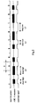
- An example of a bit sequence employing the self-clocking bit format is depicted in Figure 2 . The first trace shows the bit pattern, the second the associated rf-sequence in self-clocking bit format, where the black squares represent "rf-on"-states.
- envelope detection of an RF input signal 3 within an implant is usually performed with a simple circuit, as shown in Figure 1 , composed of a rectifier diode 4, an RC-network 1 and 2, and a comparator 7.
- the voltage across the RC-network 1 and 2 is approximately equal to the amplitude of the RF input signal 3.
- the capacitor 1 is discharged across the resistor 2.
- the voltage across the capacitor 1 tracks the envelope of the RF input signal 3.
- a comparator 7 is involved.
- the two comparator input signals are the voltage across the capacitor 1, and a reference dc-voltage 5 which is typically equal to about 50% of the rf-amplitude.
- the comparator output signal 6 is used for further signal processing.
- the envelope detection circuit proposed here comprises one rectifier diode 31, two sampling capacitors 33 and 34, a comparator 39, a flip flop 311, and a local oscillator (LO) 310 within the implant ( Fig.3 ).
- the basic idea is to sample the envelope by means of two capacitors 33 and 34 and avoid the ohmic resistor 2 of above.
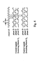
- switching matrices 35 and 36 both sampling capacitors 33 and 34 are cyclically connected to one of three ports during Phases D, C, and G, respectively, as shown in Figure 4 :
- phase D and G The duration of phases D and G is T/2, respectively (T is one clock period of the LO).
- T is one clock period of the LO.
- the duration of phase C is T.
- the two sequences are offset by a phase shift of one T.
- the state of the comparator 39 output is clocked into a flip flop 311, i.e., the active slope is the negative slope of the LO-clock signal 310.
- each of the capacitors 33 and 34 is charged and discharged about once in one bit period.
- the ratio between the incoming bit rate f bit and the LO rate f LO may not be exactly known. Nevertheless, correct bit synchronization should be guaranteed within defined limits.
- the LO is completely free-running, and the synchronization is achieved fully digital. There is no frequency- or phase tracking adjustment, e.g., by means of frequency- or phase locked loops.
- the four different states L1, H1, L2, and H2 of the incoming data stream have to be distinguished.
- ideal system behavior is assumed.
- the flip flop output 311 represents the charging state of the sampling capacitor, delayed by one LO clock period.
- Table 1 Theoretical synchronization limits for input states L1, L2, H1, and H2 Input state Minimum duration Maximum duration Output code Q L1 3T/2 0 5T/2 00 L2 7T/2 000 9T/2 0000 H1 3T/2 11 5T/2 111 H2 7T/2 1111 9T/2 11111
- the limits for minimum and maximum bit duration are imposed by the limits of the longest possible input states.
- these states are the "long-" states L2 and H2.
- Correct bit decoding can take place for a bit duration B within the range 7 2 ⁇ T ⁇ B ⁇ 9 2 ⁇ T , or equivalently, for a bit rate f bit within the range 2 9 ⁇ f LO ⁇ f bit ⁇ 2 7 ⁇ f LO .
- the corresponding range for the bit rate is [533bit/s ⁇ f bit ⁇ 685kbit/s].
- the corresponding range for the LO rate is [2.1MHz ⁇ f LO ⁇ 2.7MHz].
- Figure 5 depicts an example for correct bit decoding at different ratios between f LO and f bit .
- the four traces in each of the subplots (a), (b), and (c) show an example of an input bit pattern, the associated ASK-sequence of the bits in self-clocking format, the LO-clock signal 310, and the output of the flip flop 311, respectively.
- the LO-clock rate is equal for all subplots.
- the sampling phases where rf-amplitude are present during phase D are marked with a cross.
- the flip flop output 311 signal exactly follows the patterns of the cross-phases, delayed by one LO-clock period.
- states H1, L1, H2, and L2 are detected as flip-flop output patterns 111, 0, 11111, and 000, respectively (cf. Table 1).
- the bit rates at the upper and at the lower limits i.e., f bit ⁇ f LO 3.6 and f bit ⁇ f LO 4.4 , respectively.
- the output code allows an unambiguous detection of the four possible input states corresponding to Table 1, and therefore correct bit decoding is possible.
- the actual bit decoding is done by means of subsequent logic circuitry (not shown here).
- a triplet sequence contains states where the RF-carrier is switched on (or off) for a duration of 3B/2, resulting in states L3 and H3, respectively. These states can unambiguously be distinguished from states L1, H1, L2, and H2.
- Correct bit- and triplet decoding requires a bit duration B within the range 11 3 ⁇ T ⁇ B ⁇ 13 3 ⁇ T , or equivalently, a bit rate f bit within the range 3 13 ⁇ f LO ⁇ f bit ⁇ 3 11 ⁇ f LO .
- the corresponding range for the bit rate is [554bit/s ⁇ f bit ⁇ 655kbit/s]
- the corresponding range for the LO rate is [2.2MHz ⁇ f LO ⁇ 2.6MHz].
- Triplet sequences can very effectively be used in data transfer protocols.
- Each data word is composed of a starting triplet sequence, a particular number of information bits (with self-clocking format), and a terminating triplet sequence.
- Static information comprises e.g., information concerning phase durations or reference current levels.
- One "static information vector” comprises 64 bits. The transfer to the implant is achieved by means of one particular bit within each data word. Static information is transmitted continuously and stored in a memory within the implant. Dynamic information comprises instantaneous electrode addresses and stimulation amplitudes.
- the data word format as described herein allows high rate stimulation strategies based on sign-correlated, simultaneous stimulation pulses.
- Sign-correlated means that the pulses are 100% overlapping in time and that for each phase, the signs of current flow are identical.
- stimulation is achieved by means of symmetrical, charge balanced current pulses, with equal durations of the two phases.
- Data words in the biphasic stimulation mode are composed as follows: T ⁇ 01 or T ⁇ 10 ST SIGN EL_ AMP 1 optional : EL_ AMP 2 ... T ⁇ 0 or T ⁇ 1
- the starting triplet sequence is either T01 or T10.
- the first following bit ST carries the static information. If bit ST is the first bit of the 64-bit static information vector, the starting sequence is T01, otherwise it is T10.
- Blocks EL_AWP i are composed of 11bits, respectively. Each block contains four address bits (EL4 ...
- EL1 EL1
- AMP1 seven amplitude bits
- the number of blocks EL_AMP i defines the number of simultaneous channels. E.g., five blocks EL_AMP i with different addresses elicit five simultaneous sign-correlated pulses.
- Each data word is terminated by either sequence T0, or T1, depending on the parity of preceding bits of the data word.
- the terminating sequence is selected to obtain odd parity of the overall data word.
- triphasic mode stimulation is achieved by means of charge balanced triphasic current pulses, with equal durations of the three phases.
- the signs and amplitudes of the first and third phases are equal, and for the second phase, the sign is opposite, and the amplitude is twice.
- such pulses are designated as "triphasic symmetrical pulses”.
- Data words in the triphasic stimulation mode are similar to those of the biphasic mode: T ⁇ 010 or T ⁇ 101 ST SIGN EL_ AMP 1 optional : EL_ AMP 2 ... T ⁇ 0 or T ⁇ 1
- the starting triplet sequence is either T010 or T101.
- the first following bit ST carries the static information. If bit ST is the first bit of the 64-bit static information vector, the starting sequence is T010, otherwise it is T101.
- Blocks EL_AMP i are composed of 11bits, respectively. Each block contains four address bits (EL4 ...
- EL1 EL1
- AMP1 seven amplitude bits
- the number of blocks EL_AMP i defines the number of simultaneous channels. E.g., five blocks EL_AMP i with different addresses elicit five simultaneous sign-correlated pulses.
- Each data word is terminated by either sequence T0, or T1, depending on the parity of preceding bits of the data word.
- the terminating sequence is selected to obtain odd parity of the overall data word.
- stimulation is achieved by means of charge balanced triphasic current pulses, with equal durations of the three phases.
- the amplitudes of the first and second phases can be defined, and the third amplitude is the computed as the difference between the second and the first amplitude (zero net charge).
- Data words in the triphasic precision mode are composed as follows: T ⁇ 01010 or T ⁇ 10101 ... ST SIGN EL_AMP_ AMP 1 optional : EL_AMP_ AMP 2 ... T ⁇ 0 or T ⁇ 1
- the starting triplet sequence is either T01010, or T10101.
- the first following bit ST carries the static information. If bit ST is the first bit of the 64-bit static information vector, the starting sequence is T01010, otherwise it is T10101.
- Blocks EL_AMP_AMP 1 are composed of 18 bits, respectively.
- Each block contains four address bits (EL4 ... EL1) and seven amplitude bits (AMP_A7 ... AMP_A1) for the first phase, and seven amplitude bits (AMP_B7 ... AMP_B1) for the second phase: EL ⁇ 4... ⁇ EL ⁇ 1 AMP_A ⁇ 7.... ⁇ AMP_A ⁇ 1 AMP_B ⁇ 7.... ⁇ AMP_B ⁇ 1
- the number of blocks EL_AMP i defines the number of simultaneous channels. E.g., five blocks EL_AMP i with different addresses elicit five simultaneous sign-correlated pulses.
- Each data word is terminated by either sequence T0, or T1, depending on the parity of preceding bits of the data word.
- the terminating sequence is selected to obtain odd parity of the overall data word.
- Table 3 the maximum stimulation rates according to Eqs. (1), (2), and (3) are computed as a function of the number N of simultaneous channels.
- Table 4 Format of static information vector Data word # Bit ST Description 1 ID16 Identification (16 Bit) 2 ID15 ... ... 16 ID1 17 REF2 Reference current range (channel 1) (2 Bit) 18 REF1 19 REF2 Reference current range (channel 2) (2 Bit) 20 REF1 ... ... 47 REF2 Reference current range (channel 16) (2 Bit) 48 REF1 49 DUR8 Pulse duration (8 Bit) ... ... 56 DUR1 57 CRC8 CRC check (8 Bit) ... ... 64 CRC1
- Each individual implant is associated with a characteristic 16-bit identification sequence, which is stored to a permanent implant memory during production. Active stimulation is possible, if the 16 bits ID16 ... ID1 of the static information vector coincide with the implant specific identification sequence (however, the system can also be activated by a general, non-implant-specific 16 bit identification sequence).
- Bits REF2 REF1 define the reference current range for each stimulation channel.
- Bits DUR8 ... DUR1 defined the duration of the phases of biphasic and triphasic pulses.
- Bits CRC8 ... CRC1 are used to implement a Cyclic-Redundancy-Check for save data transfer.
- the phase duration is defined by an 8-bit word in the static information vector.
- the default setting is that the phase duration is equal for all pulses and all channels.
- the phase duration can be enhanced by adding a sequence of logical "ones" to the terminating triple sequence T0 (or T1) of a data word. Each logical "one” enhances the phase duration by exactly 25% of its default value defined by bits DUR8 ... DUR1 in the static information vector.
- the sequence of logical "ones” is terminated by either a logical "zero” or a triplet sequence.
- the terminating sequence T0 of the data word is immediately followed by starting pattern T10 (biphasic pulse), and therefore the phase duration of pulse starting immediately after T0 is equal to the value defined by bits DUR8 ... DUR1 in the static information vector.
- pattern (2) the terminating pattern T1 is followed by a logical "zero", and therefore the phase duration of elicited pulse again is equal to the value defined by bits DUR8 ... DUR1 in the static information vector.
- the terminating pattern T1 is followed by a logical "one", and therefore the phase duration of elicited pulse is enhanced by 25% of the value defined by bits DUR8 ... DUR1 in the static information vector.
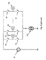
- the cochlear implant presented here allows to generate sign-correlated pulsatile stimuli in two or more simultaneously activated electrode channels, as shown in figure 7 .
- the pulse waveforms are equal in time and sign (i.e., the directions of the current flows), and the reference electrode is a remote ground electrode (monopolar stimulation).
- the pulse waveforms it is not required that the pulse waveforms be equal in time.
- the conducting tissue within the scala tympani may act as a shunt resistor between active electrodes. For example, if two neighboring electrodes sink and source a particular current simultaneously, most of the current will flow within the scala tympani from one electrode into the other, and it does not reaches the intended site of excitable nervous tissue.
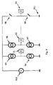
- non-overlapping pulses can be achieved, e.g., as depicted in Figure 8 (prior art). If a particular channel is active, the corresponding electrode E i 88 or 89 and the remote ground electrode RG 810 are connected to the supply voltage rail V DD 81 and the input of the stimulation current source 811 , respectively, for the first phase of the pulse, and vice versa for the second.
- the advantage of such a configuration is that the minimum supply voltage of the implant is only V DD,min ⁇ V stim,max , where V stim,max is the maximum expected voltage drop during one phase between the stimulation electrodes (assuming an ideal current source).
- Such a switching concept is not practical in general, if two or more independent current sources are activated simultaneously. This requires that the remote ground has to be connected to a fixed potential, e.g., to V DD /2, resulting in a minimum implant supply voltage of V DD,min ⁇ 2*V stim,max . This is twice the minimum supply voltage of above and results in a significantly enhanced implant power consumption.
- each stimulation electrode E i 91 or 92 is connected to two current sources 94 and 95 or 96 and 97, one for each sign, and the common remote ground electrode 93 is switched to either V DD 910 or ground potential GND 911.
- the current forced to flow into electrode RG 93 is equal to the sum of absolute values of all single electrode currents.
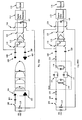
- the system for stimulation in Figure 10(a) consists of the stimulation current source I STIM (t) 101 (output resistor 115 ), switch 102, the (discrete) coupling capacitor 103 and the stimulation electrode pair, i.e., an intracochlear stimulation electrode 104 and a (remote) reference electrode 105.
- the system for measurement also consists of an electrode pair, i.e., a measurement electrode 106 (which is different from the stimulation electrode 104 ), and a (remote) reference electrode 107 (also different from the stimulation reference electrode 105 ), double switches 110, 122, and 124, sampling capacitor 123, double the (discrete) coupling capacitors 108 and 109, a differential amplifier 112 (instrumentation amplifier), a sigma-delta modulator 112, and a memory 114 (RAM).
- an electrode pair i.e., a measurement electrode 106 (which is different from the stimulation electrode 104 ), and a (remote) reference electrode 107 (also different from the stimulation reference electrode 105 ), double switches 110, 122, and 124, sampling capacitor 123, double the (discrete) coupling capacitors 108 and 109, a differential amplifier 112 (instrumentation amplifier), a sigma-delta modulator 112, and a memory 114 (RAM).
- intracochlear electrodes are replaced by nonlinear, frequency dependent interface impedances Z s ( ⁇ ) 120, and Z M ( ⁇ ) 121, respectively, as described by Mayer S., Geddes L.A., Bourland J.D., Ogborn L., "Faradic resistance of the electrode/electrolyte interface,” Med. & Biol. Eng.& Comput. (30):538-542 (1992 ); Ragheb T., Geddes L.A., “Electrical properties of metallic electrodes,” Med. & Biol. Eng.& Comput. (28):182-186 (1990 ), which is incorporated herein by reference.
- One of the two-ports 116 contains voltage source U EAP (t), representing the generated EAP. The impedances of the two reference electrodes are neglected here.
- a charge balanced pulse of a particular duration is delivered from the current source across the closed switch 102 and capacitor 103 into the tissue.
- the stimulus charges all capacitors of the system Fig.10(b) , i.e., the capacitances within the interface impedances, as well as the distributed capacitances of the tissue.
- the (passive) voltage response of the tissue to the stimulus is designated as "artifact”. Artifact amplitudes at the input of the amplifier typically are in between 100-200mV, i.e., 2 to 3 orders of magnitude higher than the expected EAP-amplitudes.
- switch 102 is switched off. This ensures that no further current can flow across the interface impedance Z s ( ⁇ ) 120, and hence relaxation procedures within the electrode interfaces are decoupled from relaxation procedures of the tissue. In order to avoid an overload condition of the instrumentation amplifier, double switch 110 is switched off during the stimulus applies.
- the stimulation pulse causes action potentials in a particular number of neurons. If an action potential occurs, the changes from the equilibrium potential difference at the membrane of the axon between inside and outside typically are about 100mV, as described by Frijns J., ten Kate J., "A model of myelinated nerve fibres for electrical prosthesis design, "Med. & Biol. Eng. & Comput. 32(4):391-398 (1994 ), which is incorporated herein by reference. However, the absolute potential change at the outside typically is less than 1mV, as described by Rattay F., "Analysis of models for external stimulation of axons," IEEE-Trans. Biomed. Eng. vol.
- the size of the residual artifact depends on the shape of the preceding stimulation pulse. Theoretically, triphasic pulses cause less residual artifact than biphasic pulses. If two of the three phases of a triphasic pulse can be set individually - as can be done in the described cochlear implant in the triphasic-precision mode - the residual artifact can be reduced to a minimum.
- double switches 110 and 122 are switched on (low impedance) for a duration of 1.7ms (measurement window), and double switch 124 remains open (high impedance).
- the input signal 106 is amplified in the instrumentation amplifier 112 by a factor of 100 (fixed gain), and subsequently inputted to the sigma-delta modulator 113.
- the sigma-delta modulator 113 (1 st order) is operated as an additional amplifier with programmable gain (possible gains: 5, 10, 20, and 40), and converts the analog signal into a high-frequency 1-bit sequence at a rate of 1.2MHz.
- the sigma-delta modulator can also be configured as an adaptive modulator with gain 5, as described by Zierhofer C.M., "Adaptive Sigma-Delta Modulation with one bit quantization,” IEEE-Trans. CAS II, vol. 47, No.5:408-415 (May 2000 ), which is incorporated herein by reference.
- the sigma-delta-sequence is directly clocked into a 2048x1-bit RAM 114.
- the measurement procedure works autonomously, and no further instructions from outside are necessary.
- a continuous-wave rf-carrier is applied.
- double switch 122 can be controlled by triplet sequence T1010, which is designated as "hold-mode interrupt". If T1010 does not appear during the measurement window, double switch 122 remains in the on-state. If T1010 appears for the first time within the measurement window, double switch 122 is opened (hold-mode). The signal value which applies immediately before switch-opening is stored in sampling capacitor 123 and applies as a constant value at the input of the sigma-delta modulator 113. If T1010 is applied during the hold-mode, double switch 122 is closed for about 2 ⁇ s and thus the signal at the output of amplifier 112 is sampled and stored in sampling capacitor 123.
- the hold-mode option allows a more accurate analysis of the EAP signal at one or more selected time instants within the measurement window. If the EAP-signal applies repetitively, an improved analysis accuracy of the overall EAP-signal can be obtained by proper selection of analysis time instants.
- hold-mode sequence T1010 interrupts the continuous-wave rf-carrier applying in the measurement window, the disturbing influence should be negligible due to its short duration of only about 12 ⁇ s.
- the sigma-delta modulator 113 can also be used to measure the size of stimulus artifacts. In contrast to EAP-measurement, this system requires that a stimulation pulse applies. After initialization of the artifact measurement system (see below), double switches 110 and 122 are open, and double switch 124 is closed. Thus an addressed measurement electrode 106 (after output capacitor 108) and the stimulation reference ground electrode 105 is connected to sampling capacitor 123. At the end of the stimulation pulse, or at a time instant controlled by the hold-mode interrupt T1010 (cf. EAP-measurement system), the sampling capacitor is connected to sigma-delta-modulator 113. The voltage analyzed by the sigma-delta modulator 113 is a constant voltage. The sigma-delta data sequence is clocked into the RAM 114.
- the artifact allows to estimate the electrode impedance. If the measurement electrode is different from the stimulation electrode, the artifact represents the voltage response to the stimulation pulse at this particular electrode position. By addressing a number of electrodes, the voltage distribution within the scala tympani as response to a stimulation pulse can be estimated.
- Starting triplet sequence T0101 is followed by eight bits MM8 ... MM1, which define the settings of the measurement mode (e.g., EAP- or artifact measurement mode, measurement electrode address, sigma-delta modulator configuration, etc.).
- the terminating sequence is either sequence T0, or T1, selected to obtain odd parity of the overall data word.
- the transfer of information from the implant to outside in general is achieved by means of load modulation.
- load modulation the quality factor of the rf-receiver circuit within the implant is reduced, and this reduction is detected outside.
- digital data are transmitted by means of load modulation at a rate of 300kbits/sec.
- Both the contents of the RAM 114, and the 64-bit static information vector can be read back.
- a self clocking bit format for read-back can be selected.
- the duration of the read-back of the 2048x1-RAM at 300kbit/sec is about 7ms.
- the maximum repetition rate for EAP-measurements is more than about 100Hz.
- non-linear decoding techniques can be applied for enhanced signal-to-noise ratio, as described by Thao N.T. and Vetterli M., "Deterministic analysis of oversampled A/D conversion and decoding improvement based on consistent estimates," IEEE-Trans. Signal Proc., vol. 42, No. 3.:519-531 (March 1994 ), which is incorporated herein by reference.
Abstract
(a.) a coding unit coupled to a communication channel, that transmits encoded digital information having defined minimum and maximum durations of logical states low and high;
(b.) a decoding unit coupled to the communication channel, that decodes information received, the decoder comprising:
(i.) a free running local oscillator LO coupled to an array of sampling capacitors, that effectively samples the information using the LO frequency;
and
(ii.) a circuit coupled to the sampling capacitors, that decodes the information despite a mismatch between nominal and actual LO frequency.
Description
- The present invention relates to bit format systems for functional electrical stimulation, and more particularly, to systems for electrostimulation of the acoustic nerve.
- Cochlear implants (inner ear prostheses) are a means to help profoundly deaf or severely hearing impaired persons. Unlike conventional hearing aids, which just apply an amplified and modified sound signal, a cochlear implant is based on direct electrical stimulation of the acoustic nerve. The intention of a cochlear implant is to stimulate nervous structures in the inner ear electrically in such a way that hearing impressions most similar to normal hearing are obtained.
- A cochlear prosthesis essentially consists of two parts, the speech processor and the implanted stimulator. The speech processor contains the power supply (batteries) of the overall system and is used to perform signal processing of the acoustic signal to extract the stimulation parameters. The stimulator (implant) generates the stimulation patterns and conducts them to the nervous tissue by means of an electrode array which usually is positioned in the scala tympani in the inner ear. The connection between the speech processor and the implanted receiver can be established by means of encoding digital information in an rf-channel involving an inductively coupled coils system.
- Decoding the information within the implant can require envelope detection. Envelope detection of an RF signal within an implant is usually performed with a simple circuit, as shown in
Figure 1 , composed of arectifier diode 4, an RC-network - Stimulation strategies employing high-rate pulsatile stimuli in multichannel electrode arrays have proved to be successful in giving very high levels of speech recognition. One example therefore is the so-called "Continuous Interleaved Sampling (CIS)"- strategy, as described by Wilson B.S., Finley C.C., Lawson D.T., Wolford R.D., Eddington D.K., Rabinowitz W.M., "Better speech recognition with cochlear implants," Nature, vol. 352:236-238 (1991), which is incorporated herein by reference. For CIS, symmetrical biphasic current pulses are used, which are strictly non-overlapping in time. The rate per channel typically is higher than 800pulses / sec
- Stimulation strategies based on simultaneous activation of electrode currents so far have not shown any advantage as compared to CIS. The basic problem is the spatial channel interaction caused by conductive tissue in the scala tympani between the stimulation electrodes. If two or more stimulation current sources are activated simultaneously, and if there is no correlation between them, the currents will flow between the active electrodes and do not reach the regions of neurons which are intended to be stimulated. The problem might get less severe with new stimulation electrode designs, where the electrodes are much closer to the modiolus as compared to existing electrodes, as described by Kuzma J., "Evaluation of new modiolus-hugging electrode concepts in a transparent model of the cochlea," proc. 4th European Symp. on Pediatric Cochlear Implantation, 's-Hertogenbosch, The Netherlands (June 1998), which is incorporated herein by reference.
- For high-rate pulsatile stimulation strategies, some patient specific parameters have to be determined. This is done some weeks after surgery in a so called "fitting"-procedure. For given phase duration of stimulation pulses and for given stimulation rate, two key parameters have to be determined for each stimulation channel:
- 1. the minimum amplitude of biphasic current pulses necessary to elicit a hearing sensation (Threshold Level, or THL); and
- 2. the amplitude resulting in a hearing sensation at a comfortable level (Most Comfort Level, or MCL).
- For stimulation, only amplitudes between MCL and THL (for each channel) are used. The dynamic range between MCL and THL typically is between 6-12dB. However, the absolute positions of MCLs and THLs vary considerably between patients, and differences can reach up to 40dB. To cover these absolute variations, the overall dynamic range for stimulation in currently used implants typically is about 60dB.
- At the moment, MCLs and THLs are estimated during the fitting procedure by applying stimulation pulses and asking the patient about his/her subjective impression. This method usually works without problems with postlingually deaf patients. However, problems occur with prelingually or congenitally deaf patients, and in this group all ages - from small children to adults - are concerned. These patients are usually neither able to interpret nor to describe hearing impressions, and only rough estimations of MCLs and THLs based on behavioral methods are possible. Especially the situation of congenitally deaf small children needs to be mentioned here. An adequate acoustic input is extremely important for the infant's speech and hearing development, and this input in many cases can be provided with a properly fitted cochlear implant.
- One approach for an objective measurement of MCLs and THLs is based on the measurement of the EAPs (Electrically evoked Action Potentials), as described by Gantz B., Brown C.J., Abbas P.J., "Intraoperative Measures of Electrically Evoked Auditory Nerve Compound Action Potentials," American Journal of Otology 15 (2):137-144 (1994), which is incorporated herein by reference. In this approach, the overall response of the acoustic nerve to an electrical stimulus is measured very close to the position of nerve excitation. This neural response is caused by the superposition of single neural responses at the outside of the axon membranes. The amplitude of the EAP at the measurement position is between 10µV and 1000µV. Information about MCL and THL at a particular electrode position can first of all be expected from the so called "amplitude growth function," as described by Brown C. J., Abbas P. J., Borland J., Bertschy M. R., "Electrically evoked whole nerve action potentials in Ineraid cochlear implant users: responses to different stimulating electrode configurations and comparison to psychophysical responses," Journal of Speech and Hearing Research, vol. 39:453-467 (June 1996), which is incorporated herein by reference. This function is the relation between the amplitude of the stimulation pulse and the peak-to-peak voltage of the EAP. Another interesting relation is the so called "recovery function". Here, stimulation is achieved with two pulses with varying interpulse-interval. The recovery function as the relation of the amplitude of the 2nd EAP and the interpulse-interval allows one to draw conclusions about the refractory properties and particular properties concerning the time resolution of the acoustic nerve.
- In accordance with one aspect of the invention, a data transmission system having a coding unit coupled to a communications channel, that transmits encoded digital information having defined minimum and maximum durations of logical states "low" and "high". A decoding unit is coupled to the communication channel, which receives and decodes the information. The decoder is comprised of a free running local oscillator LO coupled to an array of sampling capacitors, that effectively sample the information using the LO frequency. A circuit is coupled to the sampling capacitors, that decodes the information and corrects any mismatch between nominal and actual LO frequency. In another related embodiment, the encoded digitial information is contained in an RF signal. The data transmission system can be used in a cochlear implant system or an implantable system for functional electrostimulation.
- In accordance with another embodiment of the invention, a data decoder system coupled to a communication channel that decodes information received. The decoder has a free running local oscillator LO coupled to an array of sampling capacitors, that effectively sample the information using the LO frequency. A circuit is coupled to the sampling capacitors, that decodes the information and corrects any mismatch between the nominal and actual LO frequency. The encoded digital information can be contained in an RF signal. The data decoder system can be used in a cochlear implant system, or a implantable system for functional electrostimulation.
- In accordance with another emodiment of the invention, A circuit for detecting the envelope of an input signal, the circuit comprising a first sampling capacitor C1 and a second sampling capacitor C2, both capacitors coupled to ground. A first switching matrix S1 cyclically couples C1 to an input signal via a rectifier diode, the input signal being encoded with digital data; a first input of a comparator; and ground. A second switch matrix S2 cyclically couples C2 to the input signal via the rectifier diode; the first input of the comparator, and ground. A local oscillator is coupled to S1 and S2, that controls switch matrices S1 and S2, the local oscillator having period T. A dc-reference is coupled to a second input of the comparator. A flip flop is coupled to the comparator output, the flip flop being clocked by the local oscillator producing a data bit stream output indicative of the input signal's envelopeThe circuit may be used for detecting the envelope of an input signal in a cochlear implant, wherein the input signal is an RF signal encoded with digital information. In a related emodiment, a first logical state is encoded in the input signal by the sequence "RF-carrier off" followed by "RF-carrier on," and a second logical zero is encoded by the sequence "RF-carrier on" followed by "RF-carrier off." The RF input signal may be encoded using Amplitude Shift Keying Modulation, the digital data employing a self-clocking bit format. In another related embodiment, C1 and C2 are sequentially and cyclically coupled via the switching matrices to the input signal via the rectifier diode for time duration T/2 (phase D), the comparator for time duration T (phase C), and ground for time duration T/2 (phase G). S2's switching sequence is offset from S1's switching sequence by a phase shift of T. The clock of the flip flop may be activated at the end of phases C on the negative slope of the local oscillator.
- In accordance with another aspect of the invention, a method for data telemetry, where digital data is encoded into an input signal. The input signal is applied via a rectifier diode to a first switch matrix S1 and a second switch matrix S2, with S1 being coupled to a first sampling capacitor C1 and S2 being coupled to a second sampling capacitor C2. A local oscillator signal with period T is applied that controls S1 and S2, so as to cyclically couple C1 and C2 to the RF signal, a first input to a comparator, and ground. The comparator compares the first input to a DC reference voltage. The output of the comparator is then sampled via a flip flop clocked by the local oscillator, with the flip flop outputting a data bit stream representative of the envelope of the input signal having encoded information.
- In another related embodiment, the data telemetry method detects the envelope of an input signal in a cochlear implant, the input signal is an RF encoded signal encoded with digital data. A first logical state may be encoded in the input signal by the sequence "RF-carrier off" followed by "RF-carrier on," and a second logical state is encoded by the sequence "RF-carrier on" followed by "RF-carrier off." The input signal can contain special bit formats, such that the signal can be switched on or off for longer durations, such as 3B/2, B being the bit duration. In another related embodiment, the RF signal is encoded using Amplitude Shift Keying Modulation, the digital data employing a self-clocking bit format. In another embodiment, the sampling capacitors C1 and C2 are sequentially and cyclically coupled via the switching matrices to the input signal for time duration T/2 (phase D), the 1st input of the comparator for time duration T (phase C), and to ground for time duration T/2 (phase G), with S2's switching sequence being offset from S1's switching sequence by a phase shift of T. In another embodiment, the clock of the flip flop is activated at the end of phases C on the negative slope of the local oscillator.
- In another related embodiment, the data bit stream is decoded, including distinguishing four different data bit stream states, a "short low" L1 defined by a data bit stream pattern of 0 or 00, a "short high" H1 defined by a data bit stream pattern of 11 or 111, a "long low" L2 defined by a data bit stream pattern of 000 or 000, and a "long high" H2 defined by a data bit stream pattern of 1111 or 11111. Two additional bit states may be distinguished, an "extra long low" L3 defined by a data bit stream pattern of 00000 or 000000, and an "extra long high" H3 defined by a data bit stream pattern of 111111 or 1111111. Triplet sequences may also be distinguishable, a triplet sequence having a starting short state L1 or H1, followed by a sequence of strictly alternating states L3 or H3, and a terminating short state L1 or H1. The triplet sequence can be used for control and synchronization. In another related embodiment, data telemetry is achieved by data word formats having a starting triplet sequence, followed by a particular number of information bits with self-clocking format; and a terminating triplet sequence. These data word formats can allow allow high rate stimulation strategies based on sign-correlated, simultaneous stimulation pulses. In another related embodiment, the encoded information allows stimulation with sign-correlated biphasic, symmetrical pulses, stimulation with sign-correlated triphasic, symmetrical pulses, and stimulation with sign-correlated triphasic pulses. In another embodiment of the invention, a method of employing high-rate pulsatile stimulation receives encoded information, decodes the information, and applies stimulation modes based on the decoded information. The stimulaton modes comprising sign-correlated biphasic, symmetrical pulses, sign-correlated triphasic, symmetrical pulses, and sign-correlated triphasic pulses.
- In accordance with another aspect of the invention, a circuit and method for generating sign-correlated simultaneous pulsatile stimuli in a cochlear implant simultaneously applying current of same sign to a plurality of electrodes Ei. A remote ground is switched to either Vdd or ground, creating a current in the remote ground electrode equal to the sum of all single electrode Ei currents. In a related embodiment, each electrode is coupled via a switch to either a first or second current source, the second current source having the opposite sign as the first current source. In a related embodiment, the acoustic nerve is stimulated by the sign-correlated simultaneous pulsatile stimuli. The sign-correlated simultaneous pulsatile stimuli may be generated in a cochlear implant. Pulses generated can include sign-correlated biphasic, symmetrical pulses, sign-correlated triphasic, symmetrical pulses, and sign-correlated triphasic pulses.
- In another embodiment, a circuit and method for measuring electrically evoked action potentials samples an input signal across a measurement electrode and a reference electrode, the measurement electrode and reference electrode being coupled in parallel. The sampled signal is then amplified and converted into a high frequency one bit sigma-delta sequence, the sequence being stored in the implant's memory. In a related embodiment, the input signal is sampled with a first double switch. In a further related embodiment, the amplifier is a differential amplifier. The measurement electrode and the reference electrode may be coupled to the differential amplifier via coupling capacitors. In another related embodiment, the amplified analog signal is sampled and held before being digitized. In another related embodiment, the sigma-delta data sequence is transferred from memory to outside by load modulation, allowing reconstruction of the electrically evoked action potential signal from the digitized data to be achieved off-line. The method can be used in a cochlear implant.
- In another embodiment of the invention, a circuit and method for measuring stimulus artifacts samples an input an input voltage across a measurement electrode and a reference electrode with a sampling capacitor to create a sampled input. At a programmable time instant, the sampled input is output to a sigma-delta modulator via a switch, to produce a sigma-delta data sequence. The sigma-delta data sequence is then sent to memory. In a related embodiment, the sigma-delta data sequence is sent from memory to outside by load modulation, allowing reconstruction of the electrically evoked action potential signal from the digitized data to be achieved off-line.
- The foregoing features of the invention will be more readily understood by reference to the following detailed description, taken with reference to the accompanying drawings, in which:
-
Figure 1 schematically shows a standard envelope detection circuit (prior art) -
Figure 2 shows a bit sequence with a self-clocking bit format -
Figure 3 schematically shows a circuit for envelope sampling -
Figure 4 shows control signals for envelope sampling -
Figure 5 shows examples for correct bit-synchronization for fixed LO-rate fLO, and different bit rates fBIT- a. fBIT = fLO/4.0
- b. fBIT ≈ fLO/3.6
- c. fBIT ≈ fLO/4.4
-
Figure 6 shows examples of triplet sequences -
Figure 7 shows examples of sign-correlated simultaneous stimuli in different channels
Note: all simultaneous pulses are 100% overlapping in time, and
the signs of all simultaneous stimulation currents are equal- a. biphasic symmetrical
- b. triphasic symmetrical
- c. triphasic-precision
-
Figure 8 schematically shows a circuit for generation of pulses for non-simultaneous stimulation strategies (prior art) -
Figure 9 schematically shows a circuit for generation of sign-correlated simultaneous stimulation pulses -
Figure 10 EAP generation and measurement- a. schematically shows a circuit
- b. schematically shows an equivalent electrical circuit
- A cochlear implant is described which is designed to implement high rate simultaneous or non-simultaneous stimulation strategies. In the case of simultaneous stimulation, sign-correlated pulsatile stimuli are employed. Sign-correlated means that the pulses are 100% overlapping in time and that for each phase, the signs of current flow are identical. Charge balanced biphasic and triphasic pulses can be applied.
- The high data transfer rate necessary to convey sufficient stimulation information for simultaneous strategies is based on a novel data decoding concept. Data decoding is achieved by sampling of the rf-signal by means of two sampling capacitors and subsequent digital data processing. A free running local oscillator (LO) is used, where the clock frequency is about four times higher than the bit rate. The mismatch between the actual and nominal LO-clock frequency is digitally corrected.
- The implant is equipped with an EAP measurement system. For EAP measurement, one of the intra-cochlear electrodes is addressed as sensing electrode. The sensing electrode can also be positioned outside the cochlear to measure other bio-sginals. The measurement system basically consists of an instrumentation amplifier and a subsequent sigma-delta modulator. During measurement, the EAP-signal is amplified and converted to a high-frequency one-bit sigma-delta sequence. This sequence is stored to a memory in the implant. Random Access Memory (RAM) may be utilized. After measurement, these data are sent to outside by means of load modulation, and the EAP-signal reconstruction from the sigma-delta rough data can be achieved off-line.
- One possibility for encoding digital data in an rf-channel is to use Amplitude Shift Keying (ASK). For ASK, the rf-carrier is switched on and off controlled by the digital information sequence. Thus the information is contained in the envelope of the rf-signal, and decoding within the implant requires envelope detection.
- If the bandwidth of the rf-channel is sufficiently high, a self-clocking bit format can be defined. For example, a logical "one" is encoded into the sequence "rf-carrier off" followed by "rf-carrier on," a logical "zero" is encoded into the reverse sequence. Assuming a duty ratio of 50%, the mean energy flow then is independent of the data content transmitted, since the time the rf-carrier is switched on is equal to the time it is switched off. An example of a bit sequence employing the self-clocking bit format is depicted in
Figure 2 . The first trace shows the bit pattern, the second the associated rf-sequence in self-clocking bit format, where the black squares represent "rf-on"-states. Regarding the associated envelope signal intrace 3, four different states "short low, "short high," "long low," and "long high," occur. For convenience, these states are abbreviated by L1, H1, L2, and H2, where the letter ("L" or "H") characterizes the state "low" or "high," and the subsequent number defines the duration of the state in multiples of B/2 (bit duration B). States L1 and H1 appear in sequences of continuing logical "zeros" or "ones," states L2 and H2 occur, if logical "zeros" and "ones" alternate. - As stated above, envelope detection of an
RF input signal 3 within an implant is usually performed with a simple circuit, as shown inFigure 1 , composed of arectifier diode 4, an RC-network network RF input signal 3. During the "rf-off" - state, thecapacitor 1 is discharged across theresistor 2. Ideally, the voltage across thecapacitor 1 tracks the envelope of theRF input signal 3. To obtain steep edges of the output signal 6 a comparator 7 is involved. The two comparator input signals are the voltage across thecapacitor 1, and a reference dc-voltage 5 which is typically equal to about 50% of the rf-amplitude. In the standard approach, thecomparator output signal 6 is used for further signal processing. - The signal transition which necessarily occurs in the middle of each bit (cf.
Figure 1 ) can be exploited for clock generation within the implant. For bit decoding a non-retriggerable mono-flop is used, which is triggered by both the positive and the negative slope of the envelope signal, when it is in its waiting position, as described by Zierhofer C., Hochmair I., Hochmair E., "Electronic design of a cochlear implant for multichannel high-rate pulsatile stimulation strategies," IEEE Trans. Rehab. Eng., vol.3:112-116 (March 1995), which is incorporated herein by reference. - Regarding the power consumption of the RC-network, it is clear that for a given time constant τ = RC,
resistor 2 andcapacitor 1 have to be as large and as small as possible, respectively. However, for reliable operation,capacitor 1 cannot be arbitrarily small. Assuming a typical lower limit C = 10pF, and a time constant of τ = 0.1 µs results in a resistor = 10kΩ. If an rf-amplitude of U = 5V is supposed, the current through theresistor 2 in the "rf-on" - state is 500µA, resulting in a power consumption of 2.5mW. For a self clocking bit format, the mean power consumption is PR = 1.25mW. Another contribution to the power consumption stems from charging/discharging ofcapacitor 1. Assuming C = 10pF, a maximum voltage of 5V, a bit rate of fbit = 600kbit/s, and supposing that thecapacitor 1 is charged/ discharged once in a bit period, the resulting power is Pcharge = 0.075mW.
So the total power consumption of the RC-network is about
Ptot = PR + Pcharge = 1.325mW, which is considerable in a cochlear implant application. Note that for the given parameters, Pcharge is much smaller than PR. - The envelope detection circuit proposed here, as shown in
Figure 3 , comprises onerectifier diode 31, twosampling capacitors comparator 39, aflip flop 311, and a local oscillator (LO) 310 within the implant (Fig.3 ). The LO-frequency fLO is assumed to be a multiple of the bit rate fbit (typically, fLO = 4fbit). The basic idea is to sample the envelope by means of twocapacitors ohmic resistor 2 of above. By means of switchingmatrices capacitors Figure 4 : - Phase D: connection to the output of the rectifier diode 31 (input sampling),
- Phase C: connection to one input of the comparator 39 (the other input is a reference dc-
voltage 37 which is typically equal to about 50% of the rf-amplitude, as above), and - Phase G: ground potential 38 (discharging).
- The duration of phases D and G is T/2, respectively (T is one clock period of the LO). To minimize the power consumption of the
comparator 39, the duration of phase C is T. The two sequences are offset by a phase shift of one T. At the end of phases C, the state of thecomparator 39 output is clocked into aflip flop 311, i.e., the active slope is the negative slope of the LO-clock signal 310. - Employing a self clocking bit format, each of the
capacitors capacitors 
The exact size of thecapacitors capacitors - In practical applications, the ratio between the incoming bit rate fbit and the LO rate fLO may not be exactly known. Nevertheless, correct bit synchronization should be guaranteed within defined limits. In one embodiment, the LO is completely free-running, and the synchronization is achieved fully digital. There is no frequency- or phase tracking adjustment, e.g., by means of frequency- or phase locked loops.
- Employing a self clocking bit format as described above, the four different states L1, H1, L2, and H2 of the incoming data stream have to be distinguished. For the determination of theoretical synchronization limits, ideal system behavior is assumed. In particular, if one of the
sampling capacitors carrier 32 applies only during a fraction of Phase D, then the capacitor is charged instantaneously and remains charged until discharging-Phase G. Only if no rf-carrier 32 appears during Phase D, the capacitor remains uncharged. Furthermore, it is supposed that theflip flop output 311 represents the charging state of the sampling capacitor, delayed by one LO clock period. The output results are Q = 1, if the rf-carrier 32 was switched on during Phase D, and Q = 0, if it remained switched off.Table 1: Theoretical synchronization limits for input states L1, L2, H1, and H2 Input state Minimum duration Maximum duration Output code Q L1 3T/2 0 5T/2 00 L2 7T/2 000 9T/2 0000 H1 3T/2 11 5T/2 111 H2 7T/2 1111 9T/2 11111 - An unambiguous association of input stages and bit patterns of the
flip flop 311 output is summarized in Table 1. For example, a "short high", H1, is detected, if the output bit pattern (flip flop output Q) contains two or three ones. If the duration of H1 at the lower limit 3T/2, then the output bit pattern is Q = 11, a duration at the upper limit 5T/2 results in pattern Q = 111. Any duration between these limits yields two or three ones, dependent on the instantaneous phase shift between theLO clock signal 310 and theinput 32. The code word with minimum length is Q = 0 for an L1-state with duration 3T/2. The limits for minimum and maximum bit duration (assuming the self clocking bit format and a duty cycle of 50%) are imposed by the limits of the longest possible input states. For the self-clocking bit format, these states are the "long-" states L2 and H2. Correct bit decoding can take place for a bit duration B within the range
range 
-
Figure 5 depicts an example for correct bit decoding at different ratios between fLO and fbit. The four traces in each of the subplots (a), (b), and (c) show an example of an input bit pattern, the associated ASK-sequence of the bits in self-clocking format, the LO-clock signal 310, and the output of theflip flop 311, respectively. The LO-clock rate is equal for all subplots. For clarity, the sampling phases where rf-amplitude are present during phase D are marked with a cross. Theflip flop output 311 signal exactly follows the patterns of the cross-phases, delayed by one LO-clock period. In subplot (a) the ratio is exactly
flop output patterns 

- Some embodiments use so called "triplet-sequences", as shown in
figure 6 . A triplet sequence contains states where the RF-carrier is switched on (or off) for a duration of 3B/2, resulting in states L3 and H3, respectively. These states can unambiguously be distinguished from states L1, H1, L2, and H2. - Triplet sequences in general are composed of
- a. a starting short state L1 or H1;
- b. a sequence of strictly alternating states L3 and H3;
- c. terminating short state L1 or H1.
- Each triplet sequence is associated with a particular parity: triplet sequences starting with H1, i.e., T0, T01, T010, etc., have even parity, triplet sequences starting L1, i.e., T1, T10, T101, etc., have odd parity.
- The decoding of triplets L3 and H3 does not require additional analog hardware as compared to the decoding of states L1, H1, L2, and H2 only. However, an unambiguous detection of L3 and H3 results in a slight reduction of synchronization limits. Duration limits for L3 and H3 are summarized in Table 2 (which can be regarded as extension of Table 1).
Table 2: Theoretical synchronization limits for states L3 and H3 Input state Minimum duration Maximum duration Output code Q L3 11T/2 00000 13T/2 000000 H3 11T/2 111111 13T/2 1111111 - Correct bit- and triplet decoding (assuming the self clocking bit format with a duty cycle of 50%) requires a bit duration B within the range

range 
- Triplet sequences can very effectively be used in data transfer protocols. In the cochlear implant described herein, the transcutaneous transfer of stimulation information is achieved by means of data words, the bit rate is fbit = 600kbit/s. Each data word is composed of a starting triplet sequence, a particular number of information bits (with self-clocking format), and a terminating triplet sequence.
- The overall information can be divided into "static-" and "dynamic" information. Static information comprises e.g., information concerning phase durations or reference current levels. One "static information vector" comprises 64 bits. The transfer to the implant is achieved by means of one particular bit within each data word. Static information is transmitted continuously and stored in a memory within the implant. Dynamic information comprises instantaneous electrode addresses and stimulation amplitudes.
- The data word format as described herein allows high rate stimulation strategies based on sign-correlated, simultaneous stimulation pulses. Sign-correlated means that the pulses are 100% overlapping in time and that for each phase, the signs of current flow are identical.
- The following active stimulation modes are possible:
- a. stimulation with sign-correlated biphasic, symmetrical pulses;
- b. stimulation with sign-correlated triphasic, symmetrical pulses; and
- c. stimulation with sign-correlated triphasic pulses (precision mode).
- In the biphasic mode, stimulation is achieved by means of symmetrical, charge balanced current pulses, with equal durations of the two phases.
- Data words in the biphasic stimulation mode are composed as follows:

The starting triplet sequence is either T01 or T10. The first following bit ST carries the static information. If bit ST is the first bit of the 64-bit static information vector, the starting sequence is T01, otherwise it is T10. Bit SIGN defines the sign of the first phase of the biphasic pulses: BIT = '0' means cathodic first, BIT = '1' means anodic first. Blocks EL_AWPi are composed of 11bits, respectively. Each block contains four address bits (EL4 ... EL1) and seven amplitude bits (AMP7 ... AMP1):
The number of blocks EL_AMPi defines the number of simultaneous channels. E.g., five blocks EL_AMPi with different addresses elicit five simultaneous sign-correlated pulses. - Each data word is terminated by either sequence T0, or T1, depending on the parity of preceding bits of the data word. The terminating sequence is selected to obtain odd parity of the overall data word.
- With the durations 4B and 2.5B for the starting sequence T01 (or T10) and the terminating sequence T0 (or T1), respectively, and the number N of simultaneous channels, the maximum stimulation rate R2 for stimulation with biphasic pulses is

- In the triphasic mode, stimulation is achieved by means of charge balanced triphasic current pulses, with equal durations of the three phases. The signs and amplitudes of the first and third phases are equal, and for the second phase, the sign is opposite, and the amplitude is twice. In the following, such pulses are designated as "triphasic symmetrical pulses".
- Data words in the triphasic stimulation mode are similar to those of the biphasic mode:

The starting triplet sequence is either T010 or T101. The first following bit ST carries the static information. If bit ST is the first bit of the 64-bit static information vector, the starting sequence is T010, otherwise it is T101. Bit SIGN defines the sign of the first phase of the triphasic pulses: BIT = '0' means cathodic first, BIT = '1' means anodic first. Blocks EL_AMPi are composed of 11bits, respectively. Each block contains four address bits (EL4 ... EL1) and seven amplitude bits (AMP7 ... AMP1):

The number of blocks EL_AMPi defines the number of simultaneous channels. E.g., five blocks EL_AMPi with different addresses elicit five simultaneous sign-correlated pulses. - Each data word is terminated by either sequence T0, or T1, depending on the parity of preceding bits of the data word. The terminating sequence is selected to obtain odd parity of the overall data word.
- With the durations 5.5B and 2.5B for the starting sequence T010 (or T101) and the terminating sequence T0 (or T1), respectively, and the number N of simultaneous channels, the maximum stimulation rate R3 for stimulation with triphasic pulses is

- In the triphasic precision mode, stimulation is achieved by means of charge balanced triphasic current pulses, with equal durations of the three phases. Here, the amplitudes of the first and second phases can be defined, and the third amplitude is the computed as the difference between the second and the first amplitude (zero net charge).
- Data words in the triphasic precision mode are composed as follows:

The starting triplet sequence is either T01010, or T10101. The first following bit ST carries the static information. If bit ST is the first bit of the 64-bit static information vector, the starting sequence is T01010, otherwise it is T10101. Bit SIGN defines the sign of the first phase of the triphasic pulses: BIT = '0' means cathodic first, BIT = '1' means anodic first. Blocks EL_AMP_AMP1 are composed of 18 bits, respectively.
Each block contains four address bits (EL4 ... EL1) and seven amplitude bits (AMP_A7 ... AMP_A1) for the first phase, and seven amplitude bits (AMP_B7 ... AMP_B1) for the second phase:
The number of blocks EL_AMPi defines the number of simultaneous channels. E.g., five blocks EL_AMPi with different addresses elicit five simultaneous sign-correlated pulses. - Each data word is terminated by either sequence T0, or T1, depending on the parity of preceding bits of the data word. The terminating sequence is selected to obtain odd parity of the overall data word.
- With the durations 8.5B and 2.5B for the starting sequence T01010 (or T10101) and the terminating sequence T0 (or T1), respectively, and the number N of simultaneous channels, the maximum stimulation rate R3,precision for stimulation with triphasic pulses in the precision mode is

- In Table 3 the maximum stimulation rates according to Eqs. (1), (2), and (3) are computed as a function of the number N of simultaneous channels.
Table 3: Maximum stimulation rates for biphasic and triphasic pulses N R2(kpulses/sec) R3(kpulses/sec) R3,precision(kpulses/sec) 1 30.77 28.57 19.35 2 19.67 18.75 12.24 3 14.46 13.95 8.96 4 11.43 11.11 7.06 5 9.45 9.23 5.83 6 8.05 7.89 4.96 7 7.02 6.90 4.31 8 6.22 6.12 3.82 9 5.58 5.50 3.43 10 5.06 5.00 3.11 11 4.63 4.58 2.84 12 4.27 4.23 2.62 - The format of the 64-bit static information vector is shown in Table 4.
Table 4: Format of static information vector Data word # Bit ST Description 1 ID16 Identification (16 Bit) 2 ID15 ... ... 16 ID1 17 REF2 Reference current range (channel 1) (2 Bit) 18 REF1 19 REF2 Reference current range (channel 2) (2 Bit) 20 REF1 ... ... 47 REF2 Reference current range (channel 16) (2 Bit) 48 REF1 49 DUR8 Pulse duration (8 Bit) ... ... 56 DUR1 57 CRC8 CRC check (8 Bit) ... ... 64 CRC1 - Each individual implant is associated with a characteristic 16-bit identification sequence, which is stored to a permanent implant memory during production. Active stimulation is possible, if the 16 bits ID16 ... ID1 of the static information vector coincide with the implant specific identification sequence (however, the system can also be activated by a general, non-implant-specific 16 bit identification sequence). Bits REF2 REF1 define the reference current range for each stimulation channel. Bits DUR8 ... DUR1 defined the duration of the phases of biphasic and triphasic pulses. Bits CRC8 ... CRC1 are used to implement a Cyclic-Redundancy-Check for save data transfer.
- As stated above, the phase duration is defined by an 8-bit word in the static information vector. The default setting is that the phase duration is equal for all pulses and all channels. However, in some cases it might be useful to vary the phase duration of single or sign-correlated stimulation pulses. In the cochlear implant described the phase duration can be enhanced by adding a sequence of logical "ones" to the terminating triple sequence T0 (or T1) of a data word. Each logical "one" enhances the phase duration by exactly 25% of its default value defined by bits DUR8 ... DUR1 in the static information vector. The sequence of logical "ones" is terminated by either a logical "zero" or a triplet sequence.
-
- (1) ... 0 1 T0 T10 001...
- (2) ... 0 0
T1 0 1 0 1 1 T10101 ... - (3) ... 0 1 T1 10 T010 01....
- (4) ...10
T0 1 1 1 0 1 0 T01 ... - In pattern (1) the terminating sequence T0 of the data word is immediately followed by starting pattern T10 (biphasic pulse), and therefore the phase duration of pulse starting immediately after T0 is equal to the value defined by bits DUR8 ... DUR1 in the static information vector.
- In pattern (2) the terminating pattern T1 is followed by a logical "zero", and therefore the phase duration of elicited pulse again is equal to the value defined by bits DUR8 ... DUR1 in the static information vector.
- In pattern (3) the terminating pattern T1 is followed by a logical "one", and therefore the phase duration of elicited pulse is enhanced by 25% of the value defined by bits DUR8 ... DUR1 in the static information vector.
- Note that for sign-correlated pulses the enhancement of the phase duration applies for all simultaneously activated stimulation pulses.
- As stated above, the cochlear implant presented here allows to generate sign-correlated pulsatile stimuli in two or more simultaneously activated electrode channels, as shown in
figure 7 . The pulse waveforms are equal in time and sign (i.e., the directions of the current flows), and the reference electrode is a remote ground electrode (monopolar stimulation). However, it should be noted that it is not required that the pulse waveforms be equal in time. - Employing sign-correlated stimuli ensures that the sum of all currents delivered by the individual current sources is always forced to flow into the reference electrode. Thus the quantity of depolarizing (negative) charge delivered to the excitable nervous tissue is well defined. This permits - at least to a certain extent with regard to spatial channel interaction - to generate more subtly differentiated and more sophisticated activation profiles as compared to the current standard CIS-strategy, where only one profile is associated with each channel.
- If sign-correlation is not ensured, the conducting tissue within the scala tympani may act as a shunt resistor between active electrodes. For example, if two neighboring electrodes sink and source a particular current simultaneously, most of the current will flow within the scala tympani from one electrode into the other, and it does not reaches the intended site of excitable nervous tissue.
- The generation of non-overlapping pulses can be achieved, e.g., as depicted in
Figure 8 (prior art). If a particular channel is active, the correspondingelectrode E i 88 or 89 and the remoteground electrode RG 810 are connected to the supplyvoltage rail V DD 81 and the input of the stimulationcurrent source 811, respectively, for the first phase of the pulse, and vice versa for the second. The advantage of such a configuration is that the minimum supply voltage of the implant is only VDD,min ≈ Vstim,max, where Vstim,max is the maximum expected voltage drop during one phase between the stimulation electrodes (assuming an ideal current source). - Such a switching concept is not practical in general, if two or more independent current sources are activated simultaneously. This requires that the remote ground has to be connected to a fixed potential, e.g., to VDD/2, resulting in a minimum implant supply voltage of VDD,min ≈ 2*Vstim,max. This is twice the minimum supply voltage of above and results in a significantly enhanced implant power consumption.
- However, the advantage of having only VDD,min ≈ Vstim,max and at the same time allow for simultaneous stimulation of two or more channels can be maintained, if the signs and temporal waveforms of simultaneous pulses are assumed to be equal. This allows for a concept as shown in
Figure 9 . Here eachstimulation electrode E i 91 or 92 is connected to twocurrent sources remote ground electrode 93 is switched to either VDD 910 or groundpotential GND 911. For stimulation, either all upper or all lower current sources are activated simultaneously, and thus the current forced to flow intoelectrode RG 93 is equal to the sum of absolute values of all single electrode currents. - The situation of electrical stimulation and detection of the EAPs is depicted in the simple model
Figure 10(a) and in the electrical equivalent circuitFigure 10(b) . - The system for stimulation in
Figure 10(a) consists of the stimulation current source ISTIM(t) 101 (output resistor 115),switch 102, the (discrete)coupling capacitor 103 and the stimulation electrode pair, i.e., anintracochlear stimulation electrode 104 and a (remote)reference electrode 105. The system for measurement also consists of an electrode pair, i.e., a measurement electrode 106 (which is different from the stimulation electrode 104), and a (remote) reference electrode 107 (also different from the stimulation reference electrode 105),double switches sampling capacitor 123, double the (discrete)coupling capacitors delta modulator 112, and a memory 114 (RAM). - In the equivalent circuit
Figure 10(b) the intracochlear electrodes are replaced by nonlinear, frequency dependent interface impedances Zs(ω) 120, and ZM(ω) 121, respectively, as described by Mayer S., Geddes L.A., Bourland J.D., Ogborn L., "Faradic resistance of the electrode/electrolyte interface," Med. & Biol. Eng.& Comput. (30):538-542 (1992); Ragheb T., Geddes L.A., "Electrical properties of metallic electrodes," Med. & Biol. Eng.& Comput. (28):182-186 (1990), which is incorporated herein by reference. In a rough approximation, the tissue is replaced by a network composed of discrete RC two-ports 116-119, with RiCi = ε0εr/γ (i =1, 2, 3, and 4), and specific conductivity γ and relative dielectric constant εr. One of the two-ports 116 contains voltage source UEAP(t), representing the generated EAP. The impedances of the two reference electrodes are neglected here. - For stimulation, a charge balanced pulse of a particular duration is delivered from the current source across the
closed switch 102 andcapacitor 103 into the tissue. With the cochlear implant described herein, symmetrical biphasic, symmetrical triphasic, and pulses in the triphasic precision mode can be applied. The stimulus charges all capacitors of the systemFig.10(b) , i.e., the capacitances within the interface impedances, as well as the distributed capacitances of the tissue. The (passive) voltage response of the tissue to the stimulus is designated as "artifact". Artifact amplitudes at the input of the amplifier typically are in between 100-200mV, i.e., 2 to 3 orders of magnitude higher than the expected EAP-amplitudes. After the current impulse is finished,switch 102 is switched off. This ensures that no further current can flow across the interface impedance Zs(ω) 120, and hence relaxation procedures within the electrode interfaces are decoupled from relaxation procedures of the tissue. In order to avoid an overload condition of the instrumentation amplifier,double switch 110 is switched off during the stimulus applies. - The stimulation pulse causes action potentials in a particular number of neurons. If an action potential occurs, the changes from the equilibrium potential difference at the membrane of the axon between inside and outside typically are about 100mV, as described by Frijns J., ten Kate J., "A model of myelinated nerve fibres for electrical prosthesis design, "Med. & Biol. Eng. & Comput. 32(4):391-398 (1994), which is incorporated herein by reference. However, the absolute potential change at the outside typically is less than 1mV, as described by Rattay F., "Analysis of models for external stimulation of axons," IEEE-Trans. Biomed. Eng. vol. 33, No.10:974-977 (October 1986), which is incorporated herein by reference. The superposition of absolute potential differences at the outsides of many firing neurons results in the EAP (also sometimes designated as "whole nerve action potential" or "compound action potential"). The nerves are firing with a particular delay referred to the stimulating pulse (latency), and in general the EAP appears after the stimulation pulse has finished. However, when the EAP occurs, the relaxation of the tissue usually is not finished. This means that at the input of the amplifier - after the stimulus current impulse - there is a fraction of voltage UEAP(t), superposed by an exponentially decreasing voltage due to the passive relaxation of the tissue. This voltage after the current stimulus is designated in the following as "residual artifact". The size of the residual artifact depends on the shape of the preceding stimulation pulse. Theoretically, triphasic pulses cause less residual artifact than biphasic pulses. If two of the three phases of a triphasic pulse can be set individually - as can be done in the described cochlear implant in the triphasic-precision mode - the residual artifact can be reduced to a minimum.
- If the EAP-measurement mode is initiated (see below),
double switches double switch 124 remains open (high impedance). In this switch configuration, theinput signal 106 is amplified in theinstrumentation amplifier 112 by a factor of 100 (fixed gain), and subsequently inputted to the sigma-delta modulator 113. The sigma-delta modulator 113 (1st order) is operated as an additional amplifier with programmable gain (possible gains: 5, 10, 20, and 40), and converts the analog signal into a high-frequency 1-bit sequence at a rate of 1.2MHz. The sigma-delta modulator can also be configured as an adaptive modulator withgain 5, as described by Zierhofer C.M., "Adaptive Sigma-Delta Modulation with one bit quantization," IEEE-Trans. CAS II, vol. 47, No.5:408-415 (May 2000), which is incorporated herein by reference. The sigma-delta-sequence is directly clocked into a 2048x1-bit RAM 114. - Once invoked, the measurement procedure works autonomously, and no further instructions from outside are necessary. To avoid possible disturbances during measurement due to data sequences in the rf-link, usually a continuous-wave rf-carrier is applied.
- Optionally,
double switch 122 can be controlled by triplet sequence T1010, which is designated as "hold-mode interrupt". If T1010 does not appear during the measurement window,double switch 122 remains in the on-state. If T1010 appears for the first time within the measurement window,double switch 122 is opened (hold-mode). The signal value which applies immediately before switch-opening is stored insampling capacitor 123 and applies as a constant value at the input of the sigma-delta modulator 113. If T1010 is applied during the hold-mode,double switch 122 is closed for about 2µs and thus the signal at the output ofamplifier 112 is sampled and stored insampling capacitor 123. - The hold-mode option allows a more accurate analysis of the EAP signal at one or more selected time instants within the measurement window. If the EAP-signal applies repetitively, an improved analysis accuracy of the overall EAP-signal can be obtained by proper selection of analysis time instants.
- Although hold-mode sequence T1010 interrupts the continuous-wave rf-carrier applying in the measurement window, the disturbing influence should be negligible due to its short duration of only about 12µs.
- The sigma-
delta modulator 113 can also be used to measure the size of stimulus artifacts. In contrast to EAP-measurement, this system requires that a stimulation pulse applies. After initialization of the artifact measurement system (see below),double switches double switch 124 is closed. Thus an addressed measurement electrode 106 (after output capacitor 108) and the stimulationreference ground electrode 105 is connected tosampling capacitor 123. At the end of the stimulation pulse, or at a time instant controlled by the hold-mode interrupt T1010 (cf. EAP-measurement system), the sampling capacitor is connected to sigma-delta-modulator 113. The voltage analyzed by the sigma-delta modulator 113 is a constant voltage. The sigma-delta data sequence is clocked into theRAM 114. - If the measurement electrode is equal to the stimulation electrode address, the artifact allows to estimate the electrode impedance. If the measurement electrode is different from the stimulation electrode, the artifact represents the voltage response to the stimulation pulse at this particular electrode position. By addressing a number of electrodes, the voltage distribution within the scala tympani as response to a stimulation pulse can be estimated.
- The measurement mode of the cochlear implant described herein in general is invoked with the following data word:
- Starting triplet sequence T0101 is followed by eight bits MM8 ... MM1, which define the settings of the measurement mode (e.g., EAP- or artifact measurement mode, measurement electrode address, sigma-delta modulator configuration, etc.). The terminating sequence is either sequence T0, or T1, selected to obtain odd parity of the overall data word.
- The transfer of information from the implant to outside in general is achieved by means of load modulation. For load modulation, the quality factor of the rf-receiver circuit within the implant is reduced, and this reduction is detected outside. In the present application, digital data are transmitted by means of load modulation at a rate of 300kbits/sec.
- Both the contents of the
RAM 114, and the 64-bit static information vector can be read back. Optionally, a self clocking bit format for read-back can be selected. The duration of the read-back of the 2048x1-RAM at 300kbit/sec is about 7ms. Thus, together with the duration of 1.7ms for the measurement window, the maximum repetition rate for EAP-measurements is more than about 100Hz. - The read-back of the digital data stored in implant-memories is initiated by particular triplet sequences (so-called interrupts). Four different interrupts are defined (Table 5).
Table .5: Summary of read-back interrupts Logical Overall duration Function T010101 16.666µs (= 10B) Start read-back RAM (simple bit format) T101010 16.666µs (= 10B) Start read-back static information vector (simple bit format) T0101010 19.166µs (= 11.5B) Start read-back RAM (self clocking bit format) T1010101 19.166µs (= 11.5B) Start read-back static information vector (self clocking) - Although various exemplary embodiments of the invention have been disclosed, it should be apparent to those skilled in the art that various changes and modifications can be made which will achieve some of the advantages of the invention without departing from the true scope of the invention. These and other obvious modifications are intended to be covered by the appended claims.
- Certain aspects of this and related inventions may be indicated as follows:
- 1. A data transmission system comprising:
- a. a coding unit coupled to a communication channel, that transmits encoded digital information having defined minimum and maximum durations of logical states "low" and "high";
- b. a decoding unit coupled to the communication channel, that decodes information received, the decoder comprising:
- i. a free running local oscillator LO coupled to an array of sampling capacitors, that effectively samples the information using the LO frequency, and
- ii. a circuit coupled to the sampling capacitors, that decodes the information and corrects any mismatch between nominal and actual LO frequency.
- 2. A data transmission system according to 1, wherein the encoded digital information is contained in an RF signal.
- 3. A data transmission system according to 1, for use in a cochlear implant system.
- 4. A data transmission system according to 1, for use in an implantable system for functional electrostimulation.
- 5. A data decoder system comprising:
- a. a decoding unit coupled to a communication channel that decodes information received, the decoder comprising.
- i. a free running local oscillator LO coupled to an array of sampling capacitors, that effectively samples the information using the LO frequency; and
- ii. a circuit coupled to the sampling capacitors, that decodes the information and corrects any mismatch between nominal and actual LO frequency.
- a. a decoding unit coupled to a communication channel that decodes information received, the decoder comprising.
- 6. A data decoder system according to 5, wherein the encoded digital information is contained in an RF signal.
- 7. A data decoder system according to 5, that is used in a cochlear implant system.
- 8. A data decoder system according to 5, that is used in an implantable system for functional electrostimulation.
- 9. A circuit for detecting the envelope of an input signal, the circuit comprising:
- a. a first sampling capacitor C1 and a second sampling capacitor C2, both capacitors coupled to ground;
- b. a first switching matrix S1 cyclically coupling C1 to:
- i. an input signal via a rectifier diode, the input signal being encoded with digital data,
- ii. a first input of a comparator, and
- iii. ground;
- c. a second switch matrix S2 cyclically coupling C2 to:
- i. the input signal via the rectifier diode,
- ii. the first input of the comparator, and
- iii. ground;
- d. a local oscillator coupled to S1 and S2, that controls switch matrices S1 and S2, the local oscillator having period T;
- e. a de-reference coupled to a second input of the comparator; and
- f. a flip flop coupled to the comparator output, the flip flop being clocked by the local oscillator producing a data bit stream output indicative of the input signal's envelope.
- 10. A circuit according to 9, for detecting the envelope of an input signal in a cochlear implant, wherein the input signal is an RF signal encoded with digital information.
- 11. The circuit according to 9, wherein a first logical state is encoded by the sequence "RF-carrier off" followed by "RF-carrier on," and a second logical state is encoded by the sequence "RF-carrier on" followed by "RF-carrier off."
- 12. The circuit according to 11, wherein the RF input signal is encoded using Amplitude Shift Keying Modulation, the digital data employing a self-clocking bit format.
- 13. The circuit according to 11, wherein C1 and C2 are sequentially and cyclically coupled via the switching matrices to:
- a. the input signal via the rectifier diode, for time duration T/2 (phase D),
- b. the comparator for time duration T (phase C), and
- c. ground for time duration T/2 (phase G); S2's switching sequence being offset from S1's switching sequence by a phase shift of T.
- 14. The circuit according to 13, wherein the clock of the flip flop is activated at the end of phases C on the negative slope of the local oscillator.
- 15. A method for data telemetry, the method comprising:
- a. encoding digital data into an input signal;
- b. applying the input signal via a rectifier diode to a first switch matrix S1 and a second switch matrix S2, S1 being coupled to a first sampling capacitor C1, S2 being coupled to a second sampling capacitor C2;
- c. applying a local oscillator signal with period T that controls S1 and S2, so as to cyclically couple C1 and C2 to:
- i. the input signal,
- ii. a first input to a comparator, and
- iii. ground;
- d. applying a DC reference voltage to the second input of the comparator; and
- e. sampling the output of the comparator via a flip flop clocked by the local oscillator, the flip flop outputting a data bit stream, the data bit stream representative of the input signal's envelope having encoded information.
- 16. A method according to 15, for detecting the envelope of an input signal in a cochlear implant, wherein the input signal is an RF signal encoded with digital information.
- 17. A method according to 15, for data telemetry in a cochlear implant.
- 18. The method according to 15, wherein in the input signal, a first logical state is encoded by the sequence "RF-carrier off" followed by "RF-carrier on," and a second logical state is encoded by the sequence "RF-carrier on" followed by "RF-carrier off."
- 19. The method according to 18, wherein the input signal contains special bit formats, such that the signal can be switched on or off for longer durations.
- 20. The method according to 18, wherein the input signal can be switched on or off for a duration of 3B/2, B being the bit duration.
- 21. The method according to 18, wherein the RF signal is encoded using Amplitude Shift Keying Modulation, the digital data employing a self-clocking bit format.
- 22. The method according to 15, wherein the sampling capacitors C1 and C2 are sequentially and cyclically coupled via the switching matrices to:
- a. the input signal for time duration T/2 (phase D),
- b. the 1st input of the comparator for time duration T (phase C), and
- c. to ground for time duration T/2 (phase G); S2's switching sequence being offset from S1's switching sequence by a phase shift of T.
- 23. The method according to 15, further comprising decoding the data bit stream.
- 24. The method according to 23, wherein the decoding includes distinguishing four different data bit stream states, the data bit stream states comprising:
- a. a "short low" L1 defined by a data bit stream pattern of 0 or 00;
- b. a "short high" H1 defined by a data bit stream pattern of 11 or 111;
- c. a "long low" L2 defined by a data bit stream pattern of 000 or 0000; and
- d. a "long high" H2 defined by a data bit stream pattern of 1111 or 11111.
- 25. The method according to 24, wherein decoding the data bit stream includes distinguishing two additional bit states, the bit states comprising:
- a. an "extra long low" L3 defined by a data bit stream pattern of 00000 or 000000; and
- b. an "extra long high" H3 defined by a data bit stream pattern of 111111 or 1111111.
- 26. The method according to 25, wherein decoding the bit stream includes distinguishing triplet sequences, the triplet sequences comprising:
- a. a starting short state L1, or H1;
- b. a sequence of strictly alternating states L3 or H3;
- c. terminating short state L1 or H1.
- 27. The method according to 26, wherein the triplet sequence data word can be used for data control and synchronization.
- 28. The method according to 26 wherein the data word formats allow high rate stimulation strategies based on sign-correlated, simultaneous stimulation pulses.
- 29. The method according to 26, wherein data telemetry is achieved by data word formats comprising:
- a. a starting triplet sequence;
- b. a particular number of information bits with self-clocking format; and
- c. a terminating triplet sequence.
- 30. The method according to 29, wherein the encoded information allows the following active stimulation modes:
- a. stimulation with sign-correlated biphasic, symmetrical pulses;
- b. stimulation with sign-correlated triphasic, symmetrical pulses; and
- c. stimulation with sign-correlated triphasic pulses.
- 31. A method of employing high-rate pulsatile stimulation comprising
- a. recieving encoded information;
- a. decoding the information; and
- b. applying stimulation modes based on the decoded information, the stimulation modes comprising:
- i. sign-correlated biphasic, symmetrical pulses;
- ii. sign-correlated triphasic, symmetrical pulses; and
- iii. sign-correlated triphasic pulses.
- 32. A circuit for generating sign-correlated simultaneous pulsatile comprising:
- a. a plurality of circuit paths coupled in parallel between a voltage rail and ground, each circuit path comprising an electrode coupled to two current sources having opposite sign;
- b. a remote ground electrode coupled to the voltage rail via a first switch, the remote ground electrode further coupled to ground via a second switch; wherein stimulation is achieved by activating all current sources of the same sign and switching the remote ground electrode to create a current in the remote ground electrode equal to the sum of all single electrode currents.
- 33. A circuit according to 32, that generates sign-correlated simultaneous pulsatile in a cochlear implant.
- 34. A circuit according to 32 that can generate the following sign-correlated simultaneous pulsatile:
- a. sign-correlated biphasic, symmetrical pulses;
- b. sign-correlated triphasic, symmetrical pulses;
- c. and sign-correlated triphasic pulses.
- 35. A method of generating sign-correlated simultaneous pulsatile stimuli comprising:
- a. simultaneously applying current of same sign to a plurality of electrodes Ei; and
- b. switching a remote ground electrode to create a current in the remote ground electrode equal to the sum of absolute values of all single electrode Ei currents.
- 36. A method according to 35 wherein simultaneously applying current of same sign to a plurality of electrodes Ei, each electrode is coupled via a switch to either a first or second current source, the second current source having the opposite sign as the first current source.
- 37. A method according to 35, wherein the acoustic nerve is stimulated by the sign-correlated simultaneous pulsatile stimuli.
- 38. A method according to 35, that generates sign-correlated simultaneous pulsatile stimuli in a cochlear implant.
- 39. A method according to 35, wherein creating the current in the remote ground electrode, the following pulses can be created:
- a. sign-correlated biphasic, symmetrical pulses;
- b. sign-correlated triphasic, symmetrical pulses; and
- c. sign-correlated triphasic pulses.
- 40. A circuit for measurement of electrically evoked action potentials comprising:
- a. a measurement electrode coupled to a first input of a differential amplifier via a first double switch;
- b. a reference electrode coupled to a second input of the differential amplifier via the first double switch;
- c. an output of the differential amplifier coupled to an input of a sigma-delta modulator;
- d. an output of the the sigma-delta modulator coupled to memory;
- 41. A circuit for measurement according to 40, wherein the memory is RAM.
- 42. A circuit for measurement according to 40 that measures electrically evoked action potentials in a cochlear implant.
- 43. A circuit for measurement according to 40, further comprising:
- a. coupling the ouput of the differential amplifier to a sampling capacitor via a second double switch; and
- b. the sampling capacitor coupled across the input of the sigma-delta modulator, that samples the electrically evoked action potentials at select times.
- 44. A circuit for measurement according to 43, further comprising:
- a. coupling the sampling capacitor to the first coupling capacitor and a stimulation reference electrodes via a third double switch, that allows measuring of stimulus artifacts.
- 45. A method for measurement of electrically evoked action potentials comprising:
- a. sampling an input signal across a measurement electrode and a reference electrode, the electrode and reference electrode being coupled in parallel, producing a sampled signal;
- b. amplifying the sampled signal with an amplifier to produce an amplified analog signal;
- c. digitizing the amplified analog signal with a sigma-delta modulator to produce a digitized signal;
- d. outputting the digitized signal to memory; wherein during measurement, the electrically evoked action potential is amplified and converted to a high frequency one bit sigma-delta sequence, the sequence being stored in memory.
- 46. A method according to 45, wherein the input signal is sampled with a first double switch.
- 47. A method according to 45, wherein the amplified analog signal is sampled and held before being digitized.
- 48. A method according to 45, wherein the amplifier is a differential amplifier.
- 49. A method according to 48, wherein the measurement electrode and the reference electrode are coupled to the differential amplifier via coupling capacitors.
- 50. A method according to 45, further comprising sending the sigma-delta data sequence from memory to outside by load modulation, allowing reconstruction of the electrically evoked action potential signal from the digitized data to be achieved off-line.
- 51. A method according to 45, that measures electrically evoked action potentials in a cochlear implant.
- 52. A metho d for measurement of stimulus artifacts comprising:
- a. sampling an input voltage across a measurement electrode and a reference electrode with a sampling capacitor to create a sampled input;
- b. outputting, at a programmable time instant, the sampled input to a sigma-delta modulator via a switch to produce a sigma-delta data sequence;
- c. outputting the sigma-delta data sequence to memory.
- 53. A method according to 52, further comprising sending the sigma-delta data sequence from memory to outside by load modulation, allowing reconstruction of the electrically evoked action potential signal from the digitized data to be achieved off-line.
- 54. A method according to 52 that measures stimulus artifacts in a cochlear implant.
Claims (16)
- A data transmission system comprising:(a.) a coding unit coupled to a communication channel, that transmits encoded digital information having defined minimum and maximum durations of logical states low and high;(b.) a decoding unit coupled to the communication channel, that decodes information received, the decoder comprising:(i.) a free running local oscillator LO coupled to an array of sampling capacitors, that effectively samples the information using the LO frequency;
and(ii.) a circuit coupled to the sampling capacitors, that decodes the information despite a mismatch between nominal and actual LO frequency. - A data transmission system according to claim 1 wherein the encoded digital information is included in a radio frequency (RF) signal.
- A data transmission system according to claim 1 wherein it is for use in a cochlear implant system or wherein it is for use in an implantable system for functional electrostimulation.
- A data decoder system comprising:(a.) a decoding unit coupled to a communication channel that decodes information received, the decoder comprising:(i.) a free running local oscillator LO coupled to an array of sampling capacitors, that effectively samples the information using the LO frequency;
and(ii.) a circuit coupled to the sampling capacitors, that decodes the information despite a mismatch between nominal and actual LO frequency. - A data decoder system according to claim 4 wherein the encoded digital information is included in a radio frequency (RF) signal.
- A data decoder system according to claim 4 wherein it is used in a cochlear implant system or wherein it is used in an implantable system for functional electrostimulation.
- A circuit for detecting the envelope of an input signal, the circuit comprising:(a.) a first sampling capacitor C1 and a second sampling capacitor C2, both capacitors coupled to ground;(b.) a first switching matrix S1 cyclically coupling C1 to:(i.) an input signal via a rectifier diode, the input signal being encoded with digital data;(ii.) a first input of a comparator;
and(iii.) ground;(c.) a second switch matrix S2 cyclically coupling C2 to:(i.) the input signal via the rectifier diode;(ii.) the first input of the comparator;
and(iii.) ground;(d.) a local oscillator coupled to S1 and S2, that controls switch matrices S1 and S2, the local oscillator having period T;(e.) a direct current (DC)-reference coupled to a second input of the comparator;
and(f.) a flip flop coupled to the comparator output, the flip flop being clocked by the local oscillator producing a data bit stream output indicative of the input signal's envelope. - A circuit according to claim 7 wherein C1 and C2 are sequentially and cyclically coupled via the switching matrices to:(a.) the input signal via the rectifier diode, for time duration T/2 (phase D);(b.) the comparator for time duration T (phase C);
and(c.) ground for time duration T/2 (phase G); S2's switching sequence being offset from S1's switching sequence by a phase shift of T. - A method for data telemetry, the method comprising:(a.) encoding digital data into an input signal;(b.) applying the input signal via a rectifier diode to a first switch matrix S1 and a second switch matrix S2, S1 being coupled to a first sampling capacitor C1, S2 being coupled to a second sampling capacitor C2;(c.) applying a local oscillator signal with period T that controls S1 and S2, so as cyclically to couple C1 and C2 to:(i.) the input signal;(ii.) a first input to a comparator;
and(iii.) ground;(d.) applying a direct current (DC) reference voltage to the second input of the comparator;
and(e.) sampling the output of the comparator via a flip flop clocked by the local oscillator, the flip flop outputting a data bit stream, the data bit stream representative of the input signal's envelope having encoded information. - A method according to claim 9 wherein it is for data telemetry in a cochlear implant.
- A method according to claim 9 wherein the input signal has a first signal state and a second signal state, and wherein a first logical state is encoded by the sequence the first signal state followed by the second signal state, and a second logical state is encoded by the sequence the second signal state followed by the first signal state.
- A method according to claim 9 wherein the input signal is a radio frequency (RF) signal encoded using Amplitude Shift Keying Modulation, the digital data employing a self-clocking bit format.
- A method according to claim 9 wherein the sampling capacitors C1 and C2 are sequentially and cyclically coupled via the switching matrices to:(a.) the input signal for time duration T/2 (phase D);(b.) the first input of the comparator for time duration T (phase C);
and(c.) to ground for time duration T/2 (phase G); S2's switching sequence being offset from S1's switching sequence by a phase shift of T. - A method according to claim 9 wherein it further comprises decoding the data bit stream.
- A method according to claim 14 wherein the decoding includes distinguishing at least one data bit stream state from a group of data bit stream states consisting of:(a.) a short low L1 defined by a data bit stream pattern of 0 or 00;(b.) a short high H1 defined by a data bit stream pattern of 11 or 111;(c.) a long low L2 defined by a data bit stream pattern of 000 or 0000;(d.) a long high H2 defined by a data bit stream pattern of 1111 or 11111;(e.) an extra long low L3 defined by a data bit stream pattern of 00000 or 000000;
and(f.) an extra long high H3 defined by a data bit stream pattern of 111111 or 1111111. - A method according to claim 9 wherein it further comprises using the data telemetry in combination with stimulation strategies based on sign-correlated, simultaneous stimulation pulses.
Applications Claiming Priority (3)
| Application Number | Priority Date | Filing Date | Title |
|---|---|---|---|
| US14479999P | 1999-07-21 | 1999-07-21 | |
| EP03076156A EP1351554B1 (en) | 1999-07-21 | 2000-07-21 | Multi-channel cochlear implant with neural response telemetry |
| EP00949861A EP1201103B1 (en) | 1999-07-21 | 2000-07-21 | Multichannel cochlear implant with neural response telemetry |
Related Parent Applications (4)
| Application Number | Title | Priority Date | Filing Date |
|---|---|---|---|
| EP00949861A Division EP1201103B1 (en) | 1999-07-21 | 2000-07-21 | Multichannel cochlear implant with neural response telemetry |
| EP00949861.9 Division | 2000-07-21 | ||
| EP03076156A Division EP1351554B1 (en) | 1999-07-21 | 2000-07-21 | Multi-channel cochlear implant with neural response telemetry |
| EP03076156.3 Division | 2003-04-22 |
Publications (3)
| Publication Number | Publication Date |
|---|---|
| EP2291005A2 true EP2291005A2 (en) | 2011-03-02 |
| EP2291005A3 EP2291005A3 (en) | 2011-11-02 |
| EP2291005B1 EP2291005B1 (en) | 2016-09-07 |
Family
ID=22510193
Family Applications (3)
| Application Number | Title | Priority Date | Filing Date |
|---|---|---|---|
| EP10075535.4A Expired - Lifetime EP2291005B1 (en) | 1999-07-21 | 2000-07-21 | Multichannel cochlea implant having neural telemetry reaction |
| EP00949861A Expired - Lifetime EP1201103B1 (en) | 1999-07-21 | 2000-07-21 | Multichannel cochlear implant with neural response telemetry |
| EP03076156A Expired - Lifetime EP1351554B1 (en) | 1999-07-21 | 2000-07-21 | Multi-channel cochlear implant with neural response telemetry |
Family Applications After (2)
| Application Number | Title | Priority Date | Filing Date |
|---|---|---|---|
| EP00949861A Expired - Lifetime EP1201103B1 (en) | 1999-07-21 | 2000-07-21 | Multichannel cochlear implant with neural response telemetry |
| EP03076156A Expired - Lifetime EP1351554B1 (en) | 1999-07-21 | 2000-07-21 | Multi-channel cochlear implant with neural response telemetry |
Country Status (8)
| Country | Link |
|---|---|
| US (2) | US6600955B1 (en) |
| EP (3) | EP2291005B1 (en) |
| AT (2) | ATE265796T1 (en) |
| AU (1) | AU769596B2 (en) |
| CA (1) | CA2382039C (en) |
| DE (2) | DE60045643D1 (en) |
| ES (2) | ES2358189T3 (en) |
| WO (1) | WO2001006810A2 (en) |
Cited By (1)
| Publication number | Priority date | Publication date | Assignee | Title |
|---|---|---|---|---|
| WO2015009984A1 (en) | 2013-07-19 | 2015-01-22 | Med-El Elektromedizinische Geraete Gmbh | Triphasic pulses to reduce undesirable side-effects in cochlear implants |
Families Citing this family (116)
| Publication number | Priority date | Publication date | Assignee | Title |
|---|---|---|---|---|
| US8260430B2 (en) | 2010-07-01 | 2012-09-04 | Cochlear Limited | Stimulation channel selection for a stimulating medical device |
| EP1741466B1 (en) * | 1999-03-03 | 2010-09-01 | Cochlear Limited | Apparatus for optimising the operation of a cochlear implant prosthesis |
| US7917224B2 (en) * | 1999-07-21 | 2011-03-29 | Med-El Elektromedizinische Geraete Gmbh | Simultaneous stimulation for low power consumption |
| JP4819268B2 (en) * | 1999-08-26 | 2011-11-24 | メド−エル・エレクトロメディツィニシェ・ゲラーテ・ゲーエムベーハー | Electrical neural stimulation based on channel-specific sampling sequences |
| US8165686B2 (en) * | 1999-08-26 | 2012-04-24 | Med-El Elektromedizinische Geraete Gmbh | Simultaneous intracochlear stimulation |
| WO2002082982A1 (en) | 2001-04-18 | 2002-10-24 | Cochlear Limited | Method and apparatus for measurement of evoked neural response |
| AU2001272189B2 (en) | 2001-07-06 | 2008-10-09 | Cochlear Limited | Configuration of implanted devices |
| US10576275B2 (en) | 2001-07-06 | 2020-03-03 | Cochlear Limited | System and method for configuring an external device using operating parameters from an implanted device |
| US20070088335A1 (en) * | 2001-10-24 | 2007-04-19 | Med-El Elektromedizinische Geraete Gmbh | Implantable neuro-stimulation electrode with fluid reservoir |
| AU2002363103B2 (en) | 2001-10-24 | 2008-10-16 | Med-El Elektromedizinische Gerate Ges.M.B.H. | Implantable fluid delivery apparatuses and implantable electrode |
| AUPS318202A0 (en) * | 2002-06-26 | 2002-07-18 | Cochlear Limited | Parametric fitting of a cochlear implant |
| US7623929B1 (en) | 2002-08-30 | 2009-11-24 | Advanced Bionics, Llc | Current sensing coil for cochlear implant data detection |
| AU2002951218A0 (en) * | 2002-09-04 | 2002-09-19 | Cochlear Limited | Method and apparatus for measurement of evoked neural response |
| DE60336166D1 (en) * | 2002-12-02 | 2011-04-07 | Med El Elektromed Geraete Gmbh | TRANSDERMAL THROUGH MAGNETIC POWER CONTROLLED LIQUID SWITCHES |
| AU2003901538A0 (en) * | 2003-03-28 | 2003-05-01 | Cochlear Limited | Maxima search method for sensed signals |
| US20070239227A1 (en) * | 2003-08-15 | 2007-10-11 | Fridman Gene Y | Frequency modulated stimulation strategy for cochlear implant system |
| US8036753B2 (en) * | 2004-01-09 | 2011-10-11 | Cochlear Limited | Stimulation mode for cochlear implant speech coding |
| US20070173732A1 (en) * | 2004-01-29 | 2007-07-26 | Elvir Causevic | Method and apparatus for wireless brain interface |
| US8577473B2 (en) | 2004-03-08 | 2013-11-05 | Med-El Elektromedizinische Geraete Gmbh | Cochlear implant stimulation with low frequency channel privilege |
| US8965520B2 (en) * | 2004-06-15 | 2015-02-24 | Cochlear Limited | Automatic determination of the threshold of an evoked neural response |
| US8190268B2 (en) * | 2004-06-15 | 2012-05-29 | Cochlear Limited | Automatic measurement of an evoked neural response concurrent with an indication of a psychophysics reaction |
| US7801617B2 (en) * | 2005-10-31 | 2010-09-21 | Cochlear Limited | Automatic measurement of neural response concurrent with psychophysics measurement of stimulating device recipient |
| US7421298B2 (en) * | 2004-09-07 | 2008-09-02 | Cochlear Limited | Multiple channel-electrode mapping |
| US7522961B2 (en) | 2004-11-17 | 2009-04-21 | Advanced Bionics, Llc | Inner hair cell stimulation model for the use by an intra-cochlear implant |
| US7242985B1 (en) | 2004-12-03 | 2007-07-10 | Advanced Bionics Corporation | Outer hair cell stimulation model for the use by an intra—cochlear implant |
| US20060212094A1 (en) * | 2004-12-31 | 2006-09-21 | Ludwig Moser | Middle ear multi-channel electrode |
| US9314633B2 (en) | 2008-01-25 | 2016-04-19 | Cyberonics, Inc. | Contingent cardio-protection for epilepsy patients |
| US20060173493A1 (en) * | 2005-01-28 | 2006-08-03 | Cyberonics, Inc. | Multi-phasic signal for stimulation by an implantable device |
| US8027732B2 (en) * | 2005-02-15 | 2011-09-27 | Advanced Bionics, Llc | Integrated phase-shift power control transmitter for use with implantable device and method for use of the same |
| US8369958B2 (en) * | 2005-05-19 | 2013-02-05 | Cochlear Limited | Independent and concurrent processing multiple audio input signals in a prosthetic hearing implant |
| US7996212B2 (en) * | 2005-06-29 | 2011-08-09 | Fraunhofer-Gesellschaft Zur Foerderung Der Angewandten Forschung E.V. | Device, method and computer program for analyzing an audio signal |
| US7769472B2 (en) * | 2005-07-29 | 2010-08-03 | Medtronic, Inc. | Electrical stimulation lead with conformable array of electrodes |
| US7822482B2 (en) * | 2005-07-29 | 2010-10-26 | Medtronic, Inc. | Electrical stimulation lead with rounded array of electrodes |
| US8634908B2 (en) * | 2005-08-01 | 2014-01-21 | Ebr Systems, Inc. | Efficiently delivering acoustic stimulation energy to tissue |
| US7885714B2 (en) * | 2005-09-01 | 2011-02-08 | University Of Southern California | Cochlear implant fitting |
| DE102005043314B4 (en) * | 2005-09-12 | 2009-08-06 | Siemens Audiologische Technik Gmbh | Method for attenuating background noise and corresponding hearing device |
| DE602006004766D1 (en) * | 2005-09-12 | 2009-02-26 | Siemens Audiologische Technik | METHOD FOR DAMPING DISORDER NOISE AND APPROPRIATE HORIZONTAL DEVICE |
| US8784312B2 (en) | 2006-02-10 | 2014-07-22 | Cochlear Limited | Recognition of implantable medical device |
| AR059786A1 (en) * | 2006-03-09 | 2008-04-30 | Med El Elektromed Geraete Gmbh | CONFIGURATION OF COCLEAR IMPLANT ELECTRODE TO ELECT PHARMACOS |
| US7729775B1 (en) | 2006-03-21 | 2010-06-01 | Advanced Bionics, Llc | Spectral contrast enhancement in a cochlear implant speech processor |
| US7835804B2 (en) | 2006-04-18 | 2010-11-16 | Advanced Bionics, Llc | Removing artifact in evoked compound action potential recordings in neural stimulators |
| US8571675B2 (en) * | 2006-04-21 | 2013-10-29 | Cochlear Limited | Determining operating parameters for a stimulating medical device |
| US8406901B2 (en) * | 2006-04-27 | 2013-03-26 | Medtronic, Inc. | Sutureless implantable medical device fixation |
| US8046081B2 (en) * | 2006-05-18 | 2011-10-25 | Med-El Elektromedizinische Geraete Gmbh | Implanted system with DC free inputs and outputs |
| DE102006036069B4 (en) * | 2006-07-18 | 2008-09-04 | Cerbomed Gmbh | Audiological transmission system |
| US7995771B1 (en) | 2006-09-25 | 2011-08-09 | Advanced Bionics, Llc | Beamforming microphone system |
| US7864968B2 (en) * | 2006-09-25 | 2011-01-04 | Advanced Bionics, Llc | Auditory front end customization |
| US7765012B2 (en) * | 2006-11-30 | 2010-07-27 | Medtronic, Inc. | Implantable medical device including a conductive fixation element |
| US9492657B2 (en) * | 2006-11-30 | 2016-11-15 | Medtronic, Inc. | Method of implanting a medical device including a fixation element |
| US8019430B2 (en) * | 2007-03-21 | 2011-09-13 | Cochlear Limited | Stimulating auditory nerve fibers to provide pitch representation |
| US8718773B2 (en) | 2007-05-23 | 2014-05-06 | Ebr Systems, Inc. | Optimizing energy transmission in a leadless tissue stimulation system |
| US8880180B2 (en) * | 2007-07-13 | 2014-11-04 | Cochlear Limited | Assessing neural survival |
| CA2695760C (en) * | 2007-08-10 | 2014-02-04 | Med-El Elektromedizinische Geraete Gmbh | Pulse width adaptation for inductive links |
| US9008787B2 (en) | 2007-10-12 | 2015-04-14 | Cochlear Limited | Active electrode state control system |
| WO2009046502A1 (en) * | 2007-10-12 | 2009-04-16 | Cochlear Limited | Active electrode state control system |
| AU2008323718B2 (en) * | 2007-11-09 | 2011-09-22 | Med-El Elektromedizinische Geraete Gmbh | Pulsatile cochlear implant stimulation strategy |
| US8494645B2 (en) * | 2007-11-14 | 2013-07-23 | Med-El Elektromedizinische Geraete Gmbh | Cochlear implant stimulation artifacts |
| US9011508B2 (en) * | 2007-11-30 | 2015-04-21 | Lockheed Martin Corporation | Broad wavelength profile to homogenize the absorption profile in optical stimulation of nerves |
| EP2265166B1 (en) | 2008-03-25 | 2020-08-05 | EBR Systems, Inc. | Temporary electrode connection for wireless pacing systems |
| US20090287277A1 (en) * | 2008-05-19 | 2009-11-19 | Otologics, Llc | Implantable neurostimulation electrode interface |
| US20100069997A1 (en) * | 2008-09-16 | 2010-03-18 | Otologics, Llc | Neurostimulation apparatus |
| US20100106134A1 (en) * | 2008-10-15 | 2010-04-29 | Med-El Elektromedizinische Geraete Gmbh | Inner Ear Drug Delivery Device and Method |
| EP2376180B1 (en) | 2008-11-10 | 2017-06-28 | MED-EL Elektromedizinische Geräte GmbH | Hydrogel-filled drug delivery reservoirs |
| US9084551B2 (en) * | 2008-12-08 | 2015-07-21 | Medtronic Xomed, Inc. | Method and system for monitoring a nerve |
| WO2010088324A1 (en) * | 2009-01-28 | 2010-08-05 | Med-El Elktromedizinische Geraete Gmbh | Channel specific gain control including lateral suppression |
| WO2010091240A1 (en) * | 2009-02-06 | 2010-08-12 | Med-El Elektromedizinische Geraete Gmbh | Phase triggered envelope sampler |
| US8019429B2 (en) * | 2009-03-24 | 2011-09-13 | Med-El Elektromedizinische Geraete Gmbh | Carrier and envelope triggered cochlear stimulation |
| US8532782B2 (en) * | 2009-03-24 | 2013-09-10 | Med-El Elektromedizinische Geraete Gmbh | Musical fitting of cochlear implants |
| US9044588B2 (en) * | 2009-04-16 | 2015-06-02 | Cochlear Limited | Reference electrode apparatus and method for neurostimulation implants |
| US8771166B2 (en) | 2009-05-29 | 2014-07-08 | Cochlear Limited | Implantable auditory stimulation system and method with offset implanted microphones |
| EP2461866B1 (en) | 2009-08-03 | 2016-10-26 | Cochlear Limited | Implant stimulation device |
| AU2011302109B2 (en) | 2010-09-15 | 2014-08-07 | Med-El Elektromedizinische Geraete Gmbh | Method and system for accelerated fitting of cochlear implants based on current spread |
| US20120116479A1 (en) * | 2010-11-08 | 2012-05-10 | Werner Meskins | Two-wire medical implant connection |
| US9775982B2 (en) | 2010-12-29 | 2017-10-03 | Medtronic, Inc. | Implantable medical device fixation |
| US10112045B2 (en) | 2010-12-29 | 2018-10-30 | Medtronic, Inc. | Implantable medical device fixation |
| US10588524B2 (en) | 2011-05-13 | 2020-03-17 | Saluda Medical Pty Ltd | Method and apparatus for measurement of neural response |
| US9872990B2 (en) | 2011-05-13 | 2018-01-23 | Saluda Medical Pty Limited | Method and apparatus for application of a neural stimulus |
| WO2012155189A1 (en) | 2011-05-13 | 2012-11-22 | National Ict Australia Ltd | Method and apparatus for estimating neural recruitment - f |
| EP2707096B1 (en) | 2011-05-13 | 2018-08-22 | Saluda Medical Pty Limited | Apparatus for measurement of neural response |
| WO2012155185A1 (en) | 2011-05-13 | 2012-11-22 | National Ict Australia Ltd | Method and apparatus for measurement of neural response |
| US9326075B2 (en) | 2011-10-07 | 2016-04-26 | Cochlear Limited | Flexible protocol for an implanted prosthesis |
| US9216288B2 (en) | 2011-12-22 | 2015-12-22 | Cochlear Limited | Stimulation prosthesis with configurable data link |
| US10485435B2 (en) | 2012-03-26 | 2019-11-26 | Medtronic, Inc. | Pass-through implantable medical device delivery catheter with removeable distal tip |
| US9833625B2 (en) | 2012-03-26 | 2017-12-05 | Medtronic, Inc. | Implantable medical device delivery with inner and outer sheaths |
| US9717421B2 (en) | 2012-03-26 | 2017-08-01 | Medtronic, Inc. | Implantable medical device delivery catheter with tether |
| US9854982B2 (en) | 2012-03-26 | 2018-01-02 | Medtronic, Inc. | Implantable medical device deployment within a vessel |
| US9339197B2 (en) | 2012-03-26 | 2016-05-17 | Medtronic, Inc. | Intravascular implantable medical device introduction |
| US9220906B2 (en) | 2012-03-26 | 2015-12-29 | Medtronic, Inc. | Tethered implantable medical device deployment |
| WO2014011188A1 (en) | 2012-07-13 | 2014-01-16 | Advanced Bionics Ag | Cochlear implant for dynamic determination of electrode addresses and a method for its use |
| US9351648B2 (en) | 2012-08-24 | 2016-05-31 | Medtronic, Inc. | Implantable medical device electrode assembly |
| EP2908904B1 (en) | 2012-11-06 | 2020-09-23 | Saluda Medical Pty Limited | System for controlling electrical conditions of tissue |
| US11172864B2 (en) | 2013-11-15 | 2021-11-16 | Closed Loop Medical Pty Ltd | Monitoring brain neural potentials |
| AU2014353891B2 (en) | 2013-11-22 | 2020-02-06 | Saluda Medical Pty Ltd | Method and device for detecting a neural response in a neural measurement |
| US9999769B2 (en) | 2014-03-10 | 2018-06-19 | Cisco Technology, Inc. | Excitation modeling and matching |
| WO2015168735A1 (en) | 2014-05-05 | 2015-11-12 | Saluda Medical Pty Ltd | Improved neural measurement |
| WO2015199934A1 (en) * | 2014-06-25 | 2015-12-30 | Advanced Bionics Ag | Utilization of an extended inter-pulse interval in a modified continuous interleaved stimulation strategy |
| EP3838331A1 (en) | 2014-07-25 | 2021-06-23 | Saluda Medical Pty Limited | Neural stimulation dosing |
| WO2016077882A1 (en) | 2014-11-17 | 2016-05-26 | Saluda Medical Pty Ltd | Method and device for detecting a neural response in neural measurements |
| US10500399B2 (en) | 2014-12-11 | 2019-12-10 | Saluda Medical Pty Ltd | Method and device for feedback control of neural stimulation |
| EP3229890B1 (en) | 2014-12-11 | 2020-05-27 | Saluda Medical Pty Limited | Implantable electrode positioning |
| US10105539B2 (en) | 2014-12-17 | 2018-10-23 | Cochlear Limited | Configuring a stimulation unit of a hearing device |
| US10918872B2 (en) | 2015-01-19 | 2021-02-16 | Saluda Medical Pty Ltd | Method and device for neural implant communication |
| AU2016245335B2 (en) | 2015-04-09 | 2020-11-19 | Saluda Medical Pty Ltd | Electrode to nerve distance estimation |
| JP2018516150A (en) | 2015-05-31 | 2018-06-21 | サルーダ・メディカル・ピーティーワイ・リミテッド | Cranial nerve activity monitoring |
| EP3302692A4 (en) | 2015-05-31 | 2019-01-16 | Saluda Medical Pty Limited | Brain neurostimulator electrode fitting |
| AU2016269843B2 (en) | 2015-06-01 | 2021-03-04 | Closed Loop Medical Pty Ltd | Motor fibre neuromodulation |
| US11071869B2 (en) | 2016-02-24 | 2021-07-27 | Cochlear Limited | Implantable device having removable portion |
| JP6979967B2 (en) | 2016-04-05 | 2021-12-15 | サルーダ・メディカル・ピーティーワイ・リミテッド | Improved feedback control of neuromodulation |
| KR101796660B1 (en) | 2016-04-19 | 2017-11-10 | 삼성전자주식회사 | Electronic device for supporting the fingerprint verification and operating method thereof |
| US10366272B2 (en) | 2016-04-19 | 2019-07-30 | Samsung Electronics Co. Ltd | Electronic device supporting fingerprint verification and method for operating the same |
| EP3474747A4 (en) | 2016-06-24 | 2020-01-22 | Saluda Medical Pty Ltd | Neural stimulation for reduced artefact |
| US10602284B2 (en) | 2016-07-18 | 2020-03-24 | Cochlear Limited | Transducer management |
| US11944820B2 (en) | 2018-04-27 | 2024-04-02 | Saluda Medical Pty Ltd | Neurostimulation of mixed nerves |
| US10874850B2 (en) | 2018-09-28 | 2020-12-29 | Medtronic, Inc. | Impedance-based verification for delivery of implantable medical devices |
| US11331475B2 (en) | 2019-05-07 | 2022-05-17 | Medtronic, Inc. | Tether assemblies for medical device delivery systems |
| US11806530B2 (en) | 2020-04-21 | 2023-11-07 | Cochlear Limited | Balance compensation |
Family Cites Families (26)
| Publication number | Priority date | Publication date | Assignee | Title |
|---|---|---|---|---|
| US3784874A (en) * | 1971-12-23 | 1974-01-08 | Dynamic Technology Ltd | Lighting control systems |
| US4284856A (en) | 1979-09-24 | 1981-08-18 | Hochmair Ingeborg | Multi-frequency system and method for enhancing auditory stimulation and the like |
| DE3008677C2 (en) | 1980-03-06 | 1983-08-25 | Siemens AG, 1000 Berlin und 8000 München | Hearing prosthesis for electrical stimulation of the auditory nerve |
| US4385286A (en) * | 1980-07-18 | 1983-05-24 | American Microsystems, Inc. | Use of single reference voltage for analog to digital or digital to analog conversion of bipolar signals |
| US4462411A (en) * | 1981-01-07 | 1984-07-31 | The University Of Melbourne | Evoked response audiometer |
| US4532930A (en) * | 1983-04-11 | 1985-08-06 | Commonwealth Of Australia, Dept. Of Science & Technology | Cochlear implant system for an auditory prosthesis |
| US4592359A (en) * | 1985-04-02 | 1986-06-03 | The Board Of Trustees Of The Leland Stanford Junior University | Multi-channel implantable neural stimulator |
| US4742330A (en) * | 1987-05-01 | 1988-05-03 | The Regents Of The University Of California | Flash A/D converter using capacitor arrays |
| US5111419A (en) * | 1988-03-23 | 1992-05-05 | Central Institute For The Deaf | Electronic filters, signal conversion apparatus, hearing aids and methods |
| US5938691A (en) | 1989-09-22 | 1999-08-17 | Alfred E. Mann Foundation | Multichannel implantable cochlear stimulator |
| US5569307A (en) * | 1989-09-22 | 1996-10-29 | Alfred E. Mann Foundation For Scientific Research | Implantable cochlear stimulator having backtelemetry handshake signal |
| US5603726A (en) | 1989-09-22 | 1997-02-18 | Alfred E. Mann Foundation For Scientific Research | Multichannel cochlear implant system including wearable speech processor |
| WO1994014376A1 (en) * | 1992-12-22 | 1994-07-07 | Cochlear Pty. Ltd. | Telemetry system and apparatus |
| US5372142A (en) * | 1993-02-17 | 1994-12-13 | Poul Madsen Medical Devices Ltd. | Cochlear response audiometer |
| US5549658A (en) | 1994-10-24 | 1996-08-27 | Advanced Bionics Corporation | Four-Channel cochlear system with a passive, non-hermetically sealed implant |
| US5588025A (en) * | 1995-03-15 | 1996-12-24 | David Sarnoff Research Center, Inc. | Single oscillator compressed digital information receiver |
| US5601617A (en) * | 1995-04-26 | 1997-02-11 | Advanced Bionics Corporation | Multichannel cochlear prosthesis with flexible control of stimulus waveforms |
| US5649970A (en) * | 1995-08-18 | 1997-07-22 | Loeb; Gerald E. | Edge-effect electrodes for inducing spatially controlled distributions of electrical potentials in volume conductive media |
| AU708422B2 (en) * | 1995-10-19 | 1999-08-05 | Cochlear Pty. Limited | Embedded data link and protocol |
| US5824022A (en) | 1996-03-07 | 1998-10-20 | Advanced Bionics Corporation | Cochlear stimulation system employing behind-the-ear speech processor with remote control |
| CA2258008A1 (en) | 1996-06-20 | 1997-12-24 | Advanced Bionics Corporation | Self-adjusting cochlear implant system and method for fitting same |
| US5940447A (en) * | 1996-08-30 | 1999-08-17 | Motorola, Inc. | Wireless powered communication device using power signal sampling and method |
| US5818377A (en) * | 1997-04-15 | 1998-10-06 | National Semiconductor Corporation | Bipolar element averaging, digital-to-analog converter |
| CA2318407C (en) | 1998-01-12 | 2008-07-29 | Imperial College Of Science, Technology & Medicine | Audio signal processors |
| US6181969B1 (en) * | 1998-06-26 | 2001-01-30 | Advanced Bionics Corporation | Programmable current output stimulus stage for implantable device |
| US6201993B1 (en) * | 1998-12-09 | 2001-03-13 | Medtronic, Inc. | Medical device telemetry receiver having improved noise discrimination |
-
2000
- 2000-07-21 AT AT00949861T patent/ATE265796T1/en active
- 2000-07-21 DE DE60045643T patent/DE60045643D1/en not_active Expired - Lifetime
- 2000-07-21 AT AT03076156T patent/ATE498979T1/en not_active IP Right Cessation
- 2000-07-21 US US09/621,444 patent/US6600955B1/en not_active Expired - Lifetime
- 2000-07-21 EP EP10075535.4A patent/EP2291005B1/en not_active Expired - Lifetime
- 2000-07-21 WO PCT/IB2000/001151 patent/WO2001006810A2/en active IP Right Grant
- 2000-07-21 EP EP00949861A patent/EP1201103B1/en not_active Expired - Lifetime
- 2000-07-21 ES ES03076156T patent/ES2358189T3/en not_active Expired - Lifetime
- 2000-07-21 ES ES00949861T patent/ES2219367T3/en not_active Expired - Lifetime
- 2000-07-21 DE DE60010273T patent/DE60010273T2/en not_active Expired - Lifetime
- 2000-07-21 CA CA002382039A patent/CA2382039C/en not_active Expired - Lifetime
- 2000-07-21 AU AU63116/00A patent/AU769596B2/en not_active Expired
- 2000-07-21 EP EP03076156A patent/EP1351554B1/en not_active Expired - Lifetime
-
2003
- 2003-02-10 US US10/361,386 patent/US7382850B2/en not_active Expired - Fee Related
Non-Patent Citations (11)
| Title |
|---|
| BROWN C. J.; ABBAS P. J.; BORLAND J.; BERTSCHY M. R.: "Electrically evoked whole nerve action potentials in Ineraid cochlear implant users: responses to different stimulating electrode configurations and comparison to psychophysical responses", JOURNAL OF SPEECH AND HEARING RESEARCH, vol. 39, June 1996 (1996-06-01), pages 453 - 467 |
| FRIJNS J.; TEN KATE J.: "A model of myelinated nerve fibres for electrical prosthesis design", MED. & BIOL. ENG. & COMPUT., vol. 32, no. 4, 1994, pages 391 - 398 |
| GANTZ B.; BROWN C.J.; ABBAS P.J.: "Intraoperative Measures of Electrically Evoked Auditory Nerve Compound Action Potentials", AMERICAN JOURNAL OF OTOLOGY, vol. 15, no. 2, 1994, pages 137 - 144 |
| KUZMA J.: "Evaluation of new modiolus-hugging electrode concepts in a transparent model of the cochlea", PROC. 4TH EUROPEAN SYMP. ON PEDIATRIC COCHLEAR IMPLANTATION, 'S-HERTOGENBOSCH, June 1998 (1998-06-01) |
| MAYER S.; GEDDES L.A.; BOURLAND J.D.; OGBOM L.: "Faradic resistance of the electrode/electrolyte interface", MED. & BIOL. ENG.& COMPUT., 1992, pages 538 - 542 |
| RAGHEB T.; GEDDES L.A.: "Electrical properties of metallic electrodes", MED. & BIOL. ENG.& COMPUT., 1990, pages 182 - 186 |
| RATTAY F.: "Analysis of models for external stimulation of axons", IEEE-TRANS. BIOMED. ENG., vol. 33, no. 10, October 1986 (1986-10-01), pages 974 - 977 |
| THAO N.T.; VETTERLI M.: "Deterministic analysis of oversampled A/D conversion and decoding improvement based on consistent estimates", IEEE-TRANS. SIGNAL PROC., vol. 42, no. 3, March 1994 (1994-03-01), pages 519 - 531 |
| WILSON B.S.; FINLEY C.C.; LAWSON D.T.; WOLFORD R.D.; EDDINGTON D.K.; RABINOWITZ W.M.: "Better speech recognition with cochlear implants", NATURE, vol. 352, 1991, pages 236 - 238 |
| ZIERHOFER C.; HOCHMAIR I.; HOCHMAIR E.: "Electronic design of a cochlear implant for multichannel high-rate pulsatile stimulation strategies", IEEE TRANS. REHAB. ENG., vol. 3, March 1995 (1995-03-01), pages 112 - 116 |
| ZIERHOFER C.M.: "Adaptive Sigma-Delta Modulation with one bit quantization", IEEE-TRANS. CAS II, vol. 47, no. 5, May 2000 (2000-05-01), pages 408 - 415 |
Cited By (4)
| Publication number | Priority date | Publication date | Assignee | Title |
|---|---|---|---|---|
| WO2015009984A1 (en) | 2013-07-19 | 2015-01-22 | Med-El Elektromedizinische Geraete Gmbh | Triphasic pulses to reduce undesirable side-effects in cochlear implants |
| EP3021804A1 (en) * | 2013-07-19 | 2016-05-25 | MED-EL Elektromedizinische Geräte GmbH | Triphasic pulses to reduce undesirable side-effects in cochlear implants |
| EP3021804A4 (en) * | 2013-07-19 | 2017-03-29 | MED-EL Elektromedizinische Geräte GmbH | Triphasic pulses to reduce undesirable side-effects in cochlear implants |
| EP3777963A1 (en) * | 2013-07-19 | 2021-02-17 | MED-EL Elektromedizinische Geräte GmbH | Triphasic pulses to reduce undesirable side-effects in cochlear implants |
Also Published As
| Publication number | Publication date |
|---|---|
| WO2001006810A3 (en) | 2001-10-18 |
| DE60010273T2 (en) | 2005-04-21 |
| DE60045643D1 (en) | 2011-03-31 |
| EP1351554A2 (en) | 2003-10-08 |
| EP1351554A3 (en) | 2005-01-05 |
| EP1351554B1 (en) | 2011-02-16 |
| US7382850B2 (en) | 2008-06-03 |
| AU6311600A (en) | 2001-02-05 |
| US20030135247A1 (en) | 2003-07-17 |
| ES2358189T3 (en) | 2011-05-06 |
| EP2291005A3 (en) | 2011-11-02 |
| EP2291005B1 (en) | 2016-09-07 |
| US6600955B1 (en) | 2003-07-29 |
| EP1201103B1 (en) | 2004-04-28 |
| WO2001006810A2 (en) | 2001-01-25 |
| ES2219367T3 (en) | 2004-12-01 |
| CA2382039A1 (en) | 2001-01-25 |
| ATE265796T1 (en) | 2004-05-15 |
| CA2382039C (en) | 2009-12-15 |
| DE60010273D1 (en) | 2004-06-03 |
| ATE498979T1 (en) | 2011-03-15 |
| AU769596B2 (en) | 2004-01-29 |
| EP1201103A2 (en) | 2002-05-02 |
Similar Documents
| Publication | Publication Date | Title |
|---|---|---|
| EP1351554B1 (en) | Multi-channel cochlear implant with neural response telemetry | |
| US8219203B2 (en) | Cochlear implant utilizing multiple-resolution current sources and flexible data encoding | |
| US8428742B2 (en) | Simultaneous stimulation for low power consumption | |
| US4947844A (en) | Receiver/stimulator for hearing prosthesis | |
| US7076308B1 (en) | Cochlear implant and simplified method of fitting same | |
| EP0867102A1 (en) | A feedback system to control electrode voltages in a cochlear stimulator and the like | |
| AU2004201791B2 (en) | Data Transmission and Decoder System | |
| US7167754B1 (en) | Low power inverted alterphasic stimulation in a cochlear implant | |
| AU2006236022B2 (en) | Detecting an envelope of an input signal | |
| AU2008201134B2 (en) | A circuit and method for electrical measurement | |
| Spillmann et al. | Electrical stimulation of hearing by implanted cochlear electrodes in humans | |
| Ahn et al. | A neural stimulation IC based on a reconfigurable current DAC with in-situ neural recording function for cochlear implant systems | |
| Akinin et al. | An Open Expandable Data Protocol for Multipolar Stimulation in Cochlear Implants | |
| Lithgow et al. | High pulse rate electric stimuli: Current level effects on inferior colliculus units |
Legal Events
| Date | Code | Title | Description |
|---|---|---|---|
| PUAI | Public reference made under article 153(3) epc to a published international application that has entered the european phase |
Free format text: ORIGINAL CODE: 0009012 |
|
| 17P | Request for examination filed |
Effective date: 20101023 |
|
| AC | Divisional application: reference to earlier application |
Ref document number: 1201103 Country of ref document: EP Kind code of ref document: P Ref document number: 1351554 Country of ref document: EP Kind code of ref document: P |
|
| AK | Designated contracting states |
Kind code of ref document: A2 Designated state(s): AT BE CH CY DE DK ES FI FR GB GR IE IT LI LU MC NL PT SE |
|
| PUAL | Search report despatched |
Free format text: ORIGINAL CODE: 0009013 |
|
| AK | Designated contracting states |
Kind code of ref document: A3 Designated state(s): AT BE CH CY DE DK ES FI FR GB GR IE IT LI LU MC NL PT SE |
|
| RIC1 | Information provided on ipc code assigned before grant |
Ipc: H04R 25/00 20060101AFI20110929BHEP |
|
| 17Q | First examination report despatched |
Effective date: 20120604 |
|
| REG | Reference to a national code |
Ref country code: DE Ref legal event code: R079 Ref document number: 60049457 Country of ref document: DE Free format text: PREVIOUS MAIN CLASS: H04R0025000000 Ipc: A61N0001360000 |
|
| GRAP | Despatch of communication of intention to grant a patent |
Free format text: ORIGINAL CODE: EPIDOSNIGR1 |
|
| RIC1 | Information provided on ipc code assigned before grant |
Ipc: A61N 1/36 20060101AFI20160222BHEP |
|
| INTG | Intention to grant announced |
Effective date: 20160309 |
|
| GRAS | Grant fee paid |
Free format text: ORIGINAL CODE: EPIDOSNIGR3 |
|
| GRAA | (expected) grant |
Free format text: ORIGINAL CODE: 0009210 |
|
| RAP1 | Party data changed (applicant data changed or rights of an application transferred) |
Owner name: MED-EL ELEKTROMEDIZINISCHE GERAETE GMBH |
|
| AC | Divisional application: reference to earlier application |
Ref document number: 1201103 Country of ref document: EP Kind code of ref document: P Ref document number: 1351554 Country of ref document: EP Kind code of ref document: P |
|
| AK | Designated contracting states |
Kind code of ref document: B1 Designated state(s): AT BE CH CY DE DK ES FI FR GB GR IE IT LI LU MC NL PT SE |
|
| REG | Reference to a national code |
Ref country code: GB Ref legal event code: FG4D |
|
| REG | Reference to a national code |
Ref country code: CH Ref legal event code: EP |
|
| REG | Reference to a national code |
Ref country code: IE Ref legal event code: FG4D |
|
| REG | Reference to a national code |
Ref country code: AT Ref legal event code: REF Ref document number: 826291 Country of ref document: AT Kind code of ref document: T Effective date: 20161015 |
|
| REG | Reference to a national code |
Ref country code: DE Ref legal event code: R096 Ref document number: 60049457 Country of ref document: DE |
|
| REG | Reference to a national code |
Ref country code: NL Ref legal event code: MP Effective date: 20160907 |
|
| PG25 | Lapsed in a contracting state [announced via postgrant information from national office to epo] |
Ref country code: FI Free format text: LAPSE BECAUSE OF FAILURE TO SUBMIT A TRANSLATION OF THE DESCRIPTION OR TO PAY THE FEE WITHIN THE PRESCRIBED TIME-LIMIT Effective date: 20160907 |
|
| REG | Reference to a national code |
Ref country code: AT Ref legal event code: MK05 Ref document number: 826291 Country of ref document: AT Kind code of ref document: T Effective date: 20160907 |
|
| PG25 | Lapsed in a contracting state [announced via postgrant information from national office to epo] |
Ref country code: NL Free format text: LAPSE BECAUSE OF FAILURE TO SUBMIT A TRANSLATION OF THE DESCRIPTION OR TO PAY THE FEE WITHIN THE PRESCRIBED TIME-LIMIT Effective date: 20160907 Ref country code: ES Free format text: LAPSE BECAUSE OF FAILURE TO SUBMIT A TRANSLATION OF THE DESCRIPTION OR TO PAY THE FEE WITHIN THE PRESCRIBED TIME-LIMIT Effective date: 20160907 Ref country code: GR Free format text: LAPSE BECAUSE OF FAILURE TO SUBMIT A TRANSLATION OF THE DESCRIPTION OR TO PAY THE FEE WITHIN THE PRESCRIBED TIME-LIMIT Effective date: 20161208 Ref country code: SE Free format text: LAPSE BECAUSE OF FAILURE TO SUBMIT A TRANSLATION OF THE DESCRIPTION OR TO PAY THE FEE WITHIN THE PRESCRIBED TIME-LIMIT Effective date: 20160907 |
|
| PG25 | Lapsed in a contracting state [announced via postgrant information from national office to epo] |
Ref country code: BE Free format text: LAPSE BECAUSE OF FAILURE TO SUBMIT A TRANSLATION OF THE DESCRIPTION OR TO PAY THE FEE WITHIN THE PRESCRIBED TIME-LIMIT Effective date: 20160907 Ref country code: PT Free format text: LAPSE BECAUSE OF FAILURE TO SUBMIT A TRANSLATION OF THE DESCRIPTION OR TO PAY THE FEE WITHIN THE PRESCRIBED TIME-LIMIT Effective date: 20170109 Ref country code: AT Free format text: LAPSE BECAUSE OF FAILURE TO SUBMIT A TRANSLATION OF THE DESCRIPTION OR TO PAY THE FEE WITHIN THE PRESCRIBED TIME-LIMIT Effective date: 20160907 |
|
| REG | Reference to a national code |
Ref country code: DE Ref legal event code: R097 Ref document number: 60049457 Country of ref document: DE |
|
| PG25 | Lapsed in a contracting state [announced via postgrant information from national office to epo] |
Ref country code: IT Free format text: LAPSE BECAUSE OF FAILURE TO SUBMIT A TRANSLATION OF THE DESCRIPTION OR TO PAY THE FEE WITHIN THE PRESCRIBED TIME-LIMIT Effective date: 20160907 |
|
| PLBE | No opposition filed within time limit |
Free format text: ORIGINAL CODE: 0009261 |
|
| STAA | Information on the status of an ep patent application or granted ep patent |
Free format text: STATUS: NO OPPOSITION FILED WITHIN TIME LIMIT |
|
| REG | Reference to a national code |
Ref country code: FR Ref legal event code: PLFP Year of fee payment: 18 |
|
| PG25 | Lapsed in a contracting state [announced via postgrant information from national office to epo] |
Ref country code: DK Free format text: LAPSE BECAUSE OF FAILURE TO SUBMIT A TRANSLATION OF THE DESCRIPTION OR TO PAY THE FEE WITHIN THE PRESCRIBED TIME-LIMIT Effective date: 20160907 |
|
| 26N | No opposition filed |
Effective date: 20170608 |
|
| REG | Reference to a national code |
Ref country code: CH Ref legal event code: PL |
|
| GBPC | Gb: european patent ceased through non-payment of renewal fee |
Effective date: 20170721 |
|
| REG | Reference to a national code |
Ref country code: IE Ref legal event code: MM4A |
|
| PG25 | Lapsed in a contracting state [announced via postgrant information from national office to epo] |
Ref country code: GB Free format text: LAPSE BECAUSE OF NON-PAYMENT OF DUE FEES Effective date: 20170721 Ref country code: IE Free format text: LAPSE BECAUSE OF NON-PAYMENT OF DUE FEES Effective date: 20170721 Ref country code: CH Free format text: LAPSE BECAUSE OF NON-PAYMENT OF DUE FEES Effective date: 20170731 Ref country code: LI Free format text: LAPSE BECAUSE OF NON-PAYMENT OF DUE FEES Effective date: 20170731 |
|
| PG25 | Lapsed in a contracting state [announced via postgrant information from national office to epo] |
Ref country code: LU Free format text: LAPSE BECAUSE OF NON-PAYMENT OF DUE FEES Effective date: 20170721 |
|
| REG | Reference to a national code |
Ref country code: FR Ref legal event code: PLFP Year of fee payment: 19 |
|
| PG25 | Lapsed in a contracting state [announced via postgrant information from national office to epo] |
Ref country code: MC Free format text: LAPSE BECAUSE OF FAILURE TO SUBMIT A TRANSLATION OF THE DESCRIPTION OR TO PAY THE FEE WITHIN THE PRESCRIBED TIME-LIMIT Effective date: 20160907 |
|
| PG25 | Lapsed in a contracting state [announced via postgrant information from national office to epo] |
Ref country code: CY Free format text: LAPSE BECAUSE OF NON-PAYMENT OF DUE FEES Effective date: 20160907 |
|
| PGFP | Annual fee paid to national office [announced via postgrant information from national office to epo] |
Ref country code: FR Payment date: 20190729 Year of fee payment: 20 |
|
| PGFP | Annual fee paid to national office [announced via postgrant information from national office to epo] |
Ref country code: DE Payment date: 20190930 Year of fee payment: 20 |
|
| REG | Reference to a national code |
Ref country code: DE Ref legal event code: R071 Ref document number: 60049457 Country of ref document: DE |