EP2290636A1 - Dynamic weather selection - Google Patents
Dynamic weather selection Download PDFInfo
- Publication number
- EP2290636A1 EP2290636A1 EP10173909A EP10173909A EP2290636A1 EP 2290636 A1 EP2290636 A1 EP 2290636A1 EP 10173909 A EP10173909 A EP 10173909A EP 10173909 A EP10173909 A EP 10173909A EP 2290636 A1 EP2290636 A1 EP 2290636A1
- Authority
- EP
- European Patent Office
- Prior art keywords
- weather
- aircraft
- information
- band selection
- flight
- Prior art date
- Legal status (The legal status is an assumption and is not a legal conclusion. Google has not performed a legal analysis and makes no representation as to the accuracy of the status listed.)
- Granted
Links
- 238000000034 method Methods 0.000 claims abstract description 97
- 230000008569 process Effects 0.000 claims abstract description 71
- 230000009194 climbing Effects 0.000 claims description 5
- 238000012545 processing Methods 0.000 description 39
- 238000004891 communication Methods 0.000 description 38
- 230000015654 memory Effects 0.000 description 21
- 230000002085 persistent effect Effects 0.000 description 14
- 238000004364 calculation method Methods 0.000 description 9
- 238000001914 filtration Methods 0.000 description 7
- 230000005540 biological transmission Effects 0.000 description 6
- 238000012986 modification Methods 0.000 description 6
- 230000004048 modification Effects 0.000 description 6
- 238000010586 diagram Methods 0.000 description 5
- 239000004744 fabric Substances 0.000 description 5
- 230000003287 optical effect Effects 0.000 description 5
- 230000008901 benefit Effects 0.000 description 4
- 230000006870 function Effects 0.000 description 4
- 230000001133 acceleration Effects 0.000 description 3
- 230000008859 change Effects 0.000 description 3
- 230000007613 environmental effect Effects 0.000 description 3
- 239000000446 fuel Substances 0.000 description 3
- 230000004044 response Effects 0.000 description 3
- 239000004065 semiconductor Substances 0.000 description 3
- 238000004590 computer program Methods 0.000 description 2
- 238000013479 data entry Methods 0.000 description 2
- 238000005259 measurement Methods 0.000 description 2
- 238000012546 transfer Methods 0.000 description 2
- 230000001174 ascending effect Effects 0.000 description 1
- 238000009530 blood pressure measurement Methods 0.000 description 1
- 238000001514 detection method Methods 0.000 description 1
- 230000000694 effects Effects 0.000 description 1
- 238000011156 evaluation Methods 0.000 description 1
- 239000000835 fiber Substances 0.000 description 1
- 230000005484 gravity Effects 0.000 description 1
- 238000007726 management method Methods 0.000 description 1
- 230000007246 mechanism Effects 0.000 description 1
- 238000012544 monitoring process Methods 0.000 description 1
- 230000009467 reduction Effects 0.000 description 1
- 239000007787 solid Substances 0.000 description 1
- 230000003068 static effect Effects 0.000 description 1
- 210000003813 thumb Anatomy 0.000 description 1
- 230000001960 triggered effect Effects 0.000 description 1
Images


Classifications
-
- G—PHYSICS
- G08—SIGNALLING
- G08G—TRAFFIC CONTROL SYSTEMS
- G08G5/00—Traffic control systems for aircraft, e.g. air-traffic control [ATC]
- G08G5/003—Flight plan management
- G08G5/0034—Assembly of a flight plan
-
- G—PHYSICS
- G01—MEASURING; TESTING
- G01W—METEOROLOGY
- G01W1/00—Meteorology
- G01W1/08—Adaptations of balloons, missiles, or aircraft for meteorological purposes; Radiosondes
-
- G—PHYSICS
- G08—SIGNALLING
- G08G—TRAFFIC CONTROL SYSTEMS
- G08G5/00—Traffic control systems for aircraft, e.g. air-traffic control [ATC]
- G08G5/0004—Transmission of traffic-related information to or from an aircraft
- G08G5/0008—Transmission of traffic-related information to or from an aircraft with other aircraft
-
- G—PHYSICS
- G08—SIGNALLING
- G08G—TRAFFIC CONTROL SYSTEMS
- G08G5/00—Traffic control systems for aircraft, e.g. air-traffic control [ATC]
- G08G5/0004—Transmission of traffic-related information to or from an aircraft
- G08G5/0013—Transmission of traffic-related information to or from an aircraft with a ground station
-
- G—PHYSICS
- G08—SIGNALLING
- G08G—TRAFFIC CONTROL SYSTEMS
- G08G5/00—Traffic control systems for aircraft, e.g. air-traffic control [ATC]
- G08G5/0017—Arrangements for implementing traffic-related aircraft activities, e.g. arrangements for generating, displaying, acquiring or managing traffic information
- G08G5/0021—Arrangements for implementing traffic-related aircraft activities, e.g. arrangements for generating, displaying, acquiring or managing traffic information located in the aircraft
-
- G—PHYSICS
- G08—SIGNALLING
- G08G—TRAFFIC CONTROL SYSTEMS
- G08G5/00—Traffic control systems for aircraft, e.g. air-traffic control [ATC]
- G08G5/0017—Arrangements for implementing traffic-related aircraft activities, e.g. arrangements for generating, displaying, acquiring or managing traffic information
- G08G5/0026—Arrangements for implementing traffic-related aircraft activities, e.g. arrangements for generating, displaying, acquiring or managing traffic information located on the ground
-
- G—PHYSICS
- G08—SIGNALLING
- G08G—TRAFFIC CONTROL SYSTEMS
- G08G5/00—Traffic control systems for aircraft, e.g. air-traffic control [ATC]
- G08G5/003—Flight plan management
- G08G5/0039—Modification of a flight plan
-
- G—PHYSICS
- G01—MEASURING; TESTING
- G01K—MEASURING TEMPERATURE; MEASURING QUANTITY OF HEAT; THERMALLY-SENSITIVE ELEMENTS NOT OTHERWISE PROVIDED FOR
- G01K2203/00—Application of thermometers in cryogenics
Definitions
- the present disclosure relates generally aircraft and in particular to a method and apparatus for providing weather information for a trajectory of an aircraft. Still more particularly, the present disclosure relates to a method and apparatus for providing dynamically selecting three or four dimensional weather information for use in planning and updating flight trajectories.
- Flight plans are used to document basic information such as departure and arrival points, estimated time en route, various waypoints the aircraft must traverse en route, information pertaining to those waypoints, such as altitude and speed, information relating to legs of the flight between those waypoints, and aircraft predicted performance.
- This type of flight plan may be used to construct a flight trajectory including the various legs of the flight, which are connected to the various waypoints along the route.
- This flight trajectory may include a lateral trajectory defined in the horizontal plane and a vertical trajectory defined in the vertical plane.
- Weather information for the route between the departure and arrival points may affect a flight trajectory. For example, if incorrect weather is forecasted for a particular waypoint along the route of the flight plan, certain predictions for the flight path may become inaccurate, such as speed, fuel consumption, and time en route.
- revision of a flight plan may include deleting or adding waypoints, modifying the position of waypoints, or modifying the characteristics pertaining to the waypoints or legs between the waypoints, characteristics such as speed, time, or altitude, for example.
- the characteristics for various waypoints or legs between waypoints may include weather bands.
- a weather band is a collection of weather information for a specific geospatial point, such as a specific altitude or a specific three or four dimensional point in space. Weather information may include factors such as temperature, pressure, humidity, turbulence, wind speed, and wind direction.
- Ground operation centers may identify and send weather bands to an aircraft for use in determining how weather may affect flight trajectory calculations.
- the weather bands identified may be based on current or predicted weather or flight plans, or may be default weather bands non-specific to a particular flight trajectory.
- actual weather may impact a flight trajectory where the actual weather differs from the predicted weather used to calculate the predicted flight trajectory.
- different factors en route may cause an aircrew to modify the flight plan and the weather information from the ground operation center, loaded during preflight, may no longer be accurate or up-to-date for the modified flight plan.
- Inaccurate or dated weather information can result in inefficiencies for flight operations, such as an increase in fuel consumption and emissions or delay in flight time, for example.
- One or more of the different advantageous embodiments provide a system comprising a weather band selection process and a processor unit.
- the processor unit is configured to run the weather band selection process.
- the weather band selection process identifies a flight trajectory associated with an aircraft, identifies current aircraft state data, identifies weather information for the flight trajectory, and identifies a weather band selection for the aircraft using the flight trajectory and the weather information.
- One or more of the different advantageous embodiments may further provide a method for generating a weather band selection.
- weather information is identified for the flight plan.
- a number of weather bands is selected for the flight plan based on the weather information to form a weather band selection.
- the weather band selection is outputted.
- One or more of the different advantageous embodiments may further provide a method for selecting weather bands.
- a current and predicted flight trajectory is identified for a first aircraft.
- Weather information is identified for a number of locations along the current and predicted flight trajectory.
- a number of weather bands is selected for the first aircraft based on the current and predicted flight trajectory and the weather information.
- Figure 1 is a pictorial representation of a network of data processing systems in which the advantageous embodiments of the present invention may be implemented;
- FIG. 2 is an illustration of a data processing system in accordance with an advantageous embodiment
- FIG. 3 is an illustration of a weather selection environment in accordance with an advantageous embodiment
- FIG. 4 is an illustration of a dynamic weather band selection in accordance with an advantageous embodiment
- Figure 5 is an illustration of a flight trajectory in accordance with an advantageous embodiment
- FIG. 6 is an illustration of a weather band in accordance with an advantageous embodiment
- FIG. 7 is an illustration of a weather band selection in accordance with an advantageous embodiment
- FIG. 8 is an illustration of a weather band selection in accordance with an advantageous embodiment
- Figure 9 is an illustration of a process for dynamically selecting weather bands in accordance with an advantageous embodiment
- Figure 10 is an illustration of a process for generating a weather band selection in accordance with an advantageous embodiment.
- Figure 11 is an illustration of a process for selecting weather bands in accordance with an advantageous embodiment.
- Figures 1-2 exemplary diagrams of data processing environments are provided in which the advantageous embodiments of the present invention may be implemented. It should be appreciated that Figures 1-2 are only exemplary and are not intended to assert or imply any limitation with regard to the environments in which different embodiments may be implemented. Many modifications to the depicted environments may be made.
- Network data processing system 100 is a network of computers in which embodiments may be implemented.
- Network data processing system 100 contains network 102, which is the medium used to provide communications links between various devices and computers connected together within network data processing system 100.
- Network 102 may include connections, such as wire, wireless communication links, or fiber optic cables.
- server 104 and server 106 connect to network 102 along with storage unit 108.
- clients 110, 112, and 114 connect to network 102. These clients 110, 112, and 114 may be, for example, personal computers or network computers.
- server 104 provides data, such as boot files, operating system images, and applications to clients 110, 112, and 114.
- Clients 110, 112, and 114 are clients to server 104 in this example.
- Aircraft 116 also is a client that may exchange information with clients 110, 112, and 114.
- Aircraft 116 also may exchange information with servers 104 and 106.
- Aircraft 116 may exchange data with different computers through a wireless communications link while in-flight or any other type of communications link while on the ground.
- server 104, server 106, client 110, client 112, and client 114 may be computers.
- Network data processing system 100 may include additional servers, clients, and other devices not shown.
- network data processing system 100 is the Internet with network 102 representing a worldwide collection of networks and gateways that use the Transmission Control Protocol/Internet Protocol (TCP/IP) suite of protocols to communicate with one another.
- network data processing system 100 also may be implemented as a number of different types of networks, such as for example, an intranet, a local area network (LAN), or a wide area network (WAN).
- Figure 1 is intended as an example, and not as an architectural limitation for different embodiments.
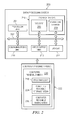
- Data processing system 200 is an example of a data processing system that may be used to implement servers and clients, such as server 104 and client 110. Further, data processing system 200 is an example of a data processing system that may be found in aircraft 116 in Figure 1 .
- data processing system 200 includes communications fabric 202, which provides communications between processor unit 204, memory 206, persistent storage 208, communications unit 210, input/output (I/O) unit 212, and display 214.
- communications fabric 202 which provides communications between processor unit 204, memory 206, persistent storage 208, communications unit 210, input/output (I/O) unit 212, and display 214.
- Processor unit 204 serves to execute instructions for software that may be loaded into memory 206.
- Processor unit 204 may be a set of one or more processors or may be a multi-processor core, depending on the particular implementation. Further, processor unit 204 may be implemented using one or more heterogeneous processor systems in which a main processor is present with secondary processors on a single chip. As another illustrative example, processor unit 204 may be a symmetric multi-processor system containing multiple processors of the same type.
- Memory 206 and persistent storage 208 are examples of storage devices 216.
- a storage device is any piece of hardware that is capable of storing information, such as, for example without limitation, data, program code in functional form, and/or other suitable information either on a temporary basis and/or a permanent basis.
- Memory 206 in these examples, may be, for example, a random access memory or any other suitable volatile or non-volatile storage device.
- Persistent storage 208 may take various forms depending on the particular implementation.
- persistent storage 208 may contain one or more components or devices.
- persistent storage 208 may be a hard drive, a flash memory, a rewritable optical disk, a rewritable magnetic tape, or some combination of the above.
- the media used by persistent storage 208 also may be removable.
- a removable hard drive may be used for persistent storage 208.
- Communications unit 210 in these examples, provides for communications with other data processing systems or devices.
- communications unit 210 is a network interface card.
- Communications unit 210 may provide communications through the use of either or both physical and wireless communications links.
- Input/output unit 212 allows for input and output of data with other devices that may be connected to data processing system 200.
- input/output unit 212 may provide a connection for user input through a keyboard, a mouse, and/or some other suitable input device. Further, input/output unit 212 may send output to a printer.
- Display 214 provides a mechanism to display information to a user.
- Instructions for the operating system, applications and/or programs may be located in storage devices 216, which are in communication with processor unit 204 through communications fabric 202. In these illustrative examples the instruction are in a functional form on persistent storage 208. These instructions may be loaded into memory 206 for execution by processor unit 204. The processes of the different embodiments may be performed by processor unit 204 using computer implemented instructions, which may be located in a memory, such as memory 206.
- program code computer usable program code
- computer readable program code that may be read and executed by a processor in processor unit 204.
- the program code in the different embodiments may be embodied on different physical or tangible computer readable media, such as memory 206 or persistent storage 208.
- Program code 218 is located in a functional form on computer readable media 220 that is selectively removable and may be loaded onto or transferred to data processing system 200 for execution by processor unit 204.
- Program code 218 and computer readable media 220 form computer program product 222 in these examples.
- computer readable media 220 may be in a tangible form, such as, for example, an optical or magnetic disc that is inserted or placed into a drive or other device that is part of persistent storage 208 for transfer onto a storage device, such as a hard drive that is part of persistent storage 208.
- computer readable media 218 also may take the form of a persistent storage, such as a hard drive, a thumb drive, or a flash memory that is connected to data processing system 200.
- the tangible form of computer readable media 218 is also referred to as computer recordable storage media. In some instances, computer readable media 220 may not be removable.
- program code 218 may be transferred to data processing system 200 from computer readable media 218 through a communications link to communications unit 210 and/or through a connection to input/output unit 212.
- the communications link and/or the connection may be physical or wireless in the illustrative examples.
- the computer readable media also may take the form of non-tangible media, such as communications links or wireless transmissions containing the program code.
- program code 218 may be downloaded over a network to persistent storage 208 from another device or data processing system for use within data processing system 200.
- program code stored in a computer readable storage medium in a server data processing system may be downloaded over a network from the server to data processing system 200.
- the data processing system providing program code 218 may be a server computer, a client computer, or some other device capable of storing and transmitting program code 218.
- the different components illustrated for data processing system 200 are not meant to provide architectural limitations to the manner in which different embodiments may be implemented.
- the different illustrative embodiments may be implemented in a data processing system including components in addition to or in place of those illustrated for data processing system 200.
- Other components shown in Figure 2 can be varied from the illustrative examples shown.
- the different embodiments may be implemented using any hardware device or system capable of executing program code.
- the data processing system may include organic components integrated with inorganic components and/or may be comprised entirely of organic components excluding a human being.
- a storage device may be comprised of an organic semiconductor.
- a storage device in data processing system 200 is any hardware apparatus that may store data.
- Memory 206, persistent storage 208 and computer readable media 220 are examples of storage devices in a tangible form.
- a bus system may be used to implement communications fabric 202 and may be comprised of one or more buses, such as a system bus or an input/output bus.
- the bus system may be implemented using any suitable type of architecture that provides for a transfer of data between different components or devices attached to the bus system.
- a communications unit may include one or more devices used to transmit and receive data, such as a modem or a network adapter.
- a memory may be, for example, memory 206 or a cache such as found in an interface and memory controller hub that may be present in communications fabric 202.
- the different advantageous embodiments recognize and take into account a number of different considerations.
- the different advantageous embodiments recognize and take into account that currently used systems select default weather bands for an aircraft to use for flight trajectory calculations. These systems do not select dynamic weather bands.
- An example of a default weather band may be a selection of weather information for three different altitudes above a static location, such as an aircraft operation center for example.
- default weather bands When default weather bands are selected, the same default altitudes are always chosen regardless of the surrounding circumstances.
- current methods increase inefficiencies in the flight trajectory calculations if the weather is out of date, not entered into a flight management computer, or provided at the wrong time.
- current systems and methods do not consider the impact of environmental factors or aircraft events when choosing weather bands. Rather, current methods only consider winds at the chosen default altitudes, which can cause the aircraft to calculate undesired top-of-climb, top-of-descent, step climbs, or deceleration and acceleration points, for example.
- the different advantageous embodiments further recognize and take into account that weather solutions for aircrew selected trajectory points may be requested during flight.
- An aircrew may desire weather solutions at waypoints along a secondary, alternative, or modified flight plan.
- Current systems also do not provide an opportunity to view current observed or forecasted weather before executing a flight plan modification for the aircrew. Rather, aircrews rely on human interpolation and manual entry for a flight plan modification, which may lead to data entry errors or less than optimized data entry.
- the different advantageous embodiments further recognize and take into account that even in the rare cases where updated weather information is available, neither the aircrew nor the ground crew know which altitudes are pertinent to the flight trajectory for the aircraft. This lack of information increases inefficiencies in calculating changes to flight trajectories in a flight plan. As a result, currently used methods involve the selection of default altitudes regardless of the actual wind effects at different altitudes, if a selection is made at all.
- an identification of a number of weather bands for flight trajectory is desirable.
- a number when referring to items, means one or more items.
- a number of weather bands is one or more weather bands. Identifying a number of weather bands that are relevant to a flight plan and/or trajectory for an aircraft may provide for more accurate and efficient planning in operating the aircraft.
- one or more of the different advantageous embodiments may provide a system comprising a weather band selection process and a processor unit.
- the processor unit is configured to run the weather band selection process.
- the weather band selection process identifies a flight trajectory associated with an aircraft, identifies weather information for the flight trajectory, and identifies a weather band selection for the aircraft using the flight trajectory, aircraft information and the weather information.
- One or more of the different advantageous embodiments may further provide a method for generating a weather band selection.
- weather information is identified for the flight plan.
- a number of weather bands is selected for the flight plan based on the weather information to form a weather band selection.
- the weather band selection is outputted.
- One or more of the different advantageous embodiments may further provide a method for selecting weather bands.
- a current and predicted flight trajectory is identified for a first aircraft.
- Weather information is identified for a number of locations along the current and predicted flight trajectory.
- a number of weather bands is selected for the first aircraft based on the current and predicted flight trajectory and the weather information.
- Weather selection environment 300 may be implemented in an environment such as network 102 in Figure 1 .
- Weather selection environment 300 includes number of other ground systems 301, number of operation centers 302, number of aircraft 304, and weather selection system 306.
- Number of operation centers 302 may include airline operation centers at various locations, and/or any other type of operation centers.
- Number of operation centers 302 includes computer system 303 and operation personnel 308.
- Computer system 303 may include a number of computers. As used herein, a number refers to one or more computers. The number of computers of computer system 303 may be networked in an environment such as network 102 in Figure 1 .
- Number of aircraft 304 may be any type of aircraft including, without limitation, jet engine aircraft, twin engine aircraft, single engine aircraft, spacecraft, and/or any other suitable type of aircraft.
- Aircraft 305 may be an example of one implementation of number of aircraft 304.
- Aircraft 305 includes computer system 309 and aircrew 310.
- Computer system 309 may include a number of computers.
- the number of computers of computer system 303 may be networked in an environment such as network 102 in Figure 1 .
- Number of other ground systems 301 may include, without limitation, weather reporting stations, weather monitoring stations, and/or any other suitable ground system.
- computer system 303 may also include trajectory calculation process 307. Trajectory calculation process 307 may be used to predict a trajectory for flight plan of an aircraft, such as aircraft 305, and send the trajectory to the aircraft.
- computer system 309 of aircraft 305 includes trajectory calculation process 311. Trajectory calculation process 311 may be used to predict a trajectory of aircraft 305 using information received from weather selection system 306.
- weather selection system 306 is located in a remote location from number of operation centers 302 and number of aircraft 304.
- weather selection system 306 may be operated by a third party service.
- Weather selection system 306 uses communications unit 312 to interact with number of operations centers 302 and number of aircraft 304.
- Weather selection system 306 may be implemented using one or more of data processing system 200.
- Communications unit 312 in these examples, provides for communications with other data processing systems or devices.
- communications unit 312 may be a network interface card.
- Communications unit 312 may provide communications through the use of either or both physical and wireless communications links.
- Communications unit 312 may be integrated with processor 314 and/or may be independent from and accessible to processor 314.
- Processor 314 and/or communications unit 312 may access number of databases 316.
- Number of databases 316 may include various databases with information such as, ground weather, aircraft weather, aircraft state data, aircraft predictions, aircraft model identification, flight plans, and/or any other suitable information.
- Processor 314 may receive weather information 318.
- weather information 318 may be accessed using number of databases 316.
- weather information 318 may be received from number of operation centers 302, number of aircraft 304, aircraft 305, and/or number of other ground systems 301.
- operation personnel 308 of number of operation centers 302 may send updated weather information 318 to weather selection system 306.
- aircrew 310 of aircraft 305 may send observed weather information 318 to weather selection system 306.
- weather information 317 from number of other ground systems 301 may be transmitted to and/or retrieved by weather selection system 306 using computer system 315.
- Computer system 315 may be an example of one implementation of data processing system 200 in Figure 2 , for example.
- Processor 314 includes weather band selection process 320.
- Weather band selection process 320 uses weather information 318 to generate weather band selection 322.
- Weather band selection 322 may then be sent to number of operation centers 302 and/or number of aircraft 304.
- weather selection environment 300 in Figure 3 is not meant to imply physical or architectural limitations to the manner in which different advantageous embodiments may be implemented.
- Other components in addition to and/or in place of the ones illustrated may be used. Some components may be unnecessary in some advantageous embodiments.
- the blocks are presented to illustrate some functional components. One or more of these blocks may be combined and/or divided into different blocks when implemented in different advantageous embodiments.
- communications unit 312 may be integrated with processor 314 in a manner illustrated by Figure 2 .
- weather selection system 306 may be distributed across or located in at least one of a remote location, number of operation centers 302, and/or number of aircraft 304.
- the phrase "at least one of”, when used with a list of items, means that different combinations of one or more of the listed items may be used and only one of each item in the list may be needed.
- "at least one of item A, item B, and item C" may include, for example, without limitation, item A or item A and item B. This example also may include item A, item B, and item C or item B and item C.
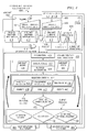
- Dynamic weather band selection system 400 is an illustrative example of one implementation of weather selection system 306 in Figure 3 .
- Dynamic weather band selection system 400 may be implemented using a data processing system, such as data processing system 200 in Figure 2 .
- Dynamic weather band selection system 400 includes dynamic weather band processor 402.
- Dynamic weather band processor 402 is configured to choose climb, cruise, and descent weather that are specific to a particular flight trajectory.
- the dynamic weather bands and weather information are chosen based on aircraft type, on-board equipage, current and forecasted weather, flight plan, phase of flight, aircraft events, aircraft state data, and the computed trajectory for the flight plan.
- Phase of flight may include, for example, without limitation, on-ground, climbing, cruising, descending, landing, and/or any other suitable phase of flight.
- Aircraft events may include, for example, without limitation, gear extension, gear retraction, flap extension, flap retraction, step climb points, step down points, and/or any other suitable aircraft event where there are changes in aircraft pitch, speed, and/or thrust.
- dynamic weather band processor 402 continually evaluates information received in order to dynamically select weather for a flight plan.
- dynamic weather band processor 402 may be triggered to evaluate information by request 408, push 407, or some other event to dynamically select weather bands for a particular flight plan.
- Request 408 may be initiated by either aircraft initiated weather request 404 or ground initiated request 406.
- Request 408 may include a specific flight plan used by dynamic weather band processor 402 to dynamically select weather bands for the specific flight plan in response to request 408, for example.
- Push 407 may be an automatic push of a flight plan to dynamic weather band processor 402 to calculate a new weather solution before any request is made by an aircraft.
- the event may be, for example, without limitation, receipt of updated weather information, a change in a flight plan, or some other suitable event.
- Dynamic weather band processor 402 may receive information from a number of databases, such as ground weather information 410, aircraft weather information 412, aircraft current state data 416, and aircraft predictions 418.
- Ground weather information 410, aircraft weather information 412, aircraft current state data 416, and aircraft predictions 418 may be illustrative examples of one implementation of number of databases 316 in Figure 3 .
- Dynamic weather band processor 402 may also receive information directly from a number of aircraft and/or operation centers, such as aircraft 403 and operation center 405, for example.
- Ground weather information 410 may include information collected from weather sources, such as, for example, without limitation, National Oceanic and Atmospheric Administration (NOAA). Ground weather information 410 may also include information about weather local to a particular operation center, forecasted weather information for a number of locations, and/or any other suitable type of ground weather information. Operation center 405 may be an illustrative example of one implementation of an operation center that sends weather information to ground weather information 410.
- NOAA National Oceanic and Atmospheric Administration
- Aircraft weather information 412 may include weather directly reported or derived from a number of aircraft, such as number of aircraft 304 in Figure 3 , for example.
- Aircraft 403 may be an illustrative example of one implementation of an aircraft that directly sends currently observed weather information to aircraft weather information 412.
- Aircraft weather information 412 may include information such as, without limitation, temperature, pressure, turbulence, icing, wind speed, wind direction, wind vertical acceleration, and/or any other suitable information pertaining to a number of different points for a particular flight path and/or trajectory.
- Dynamic weather band processor 402 may receive weather information 414 from a number of different sources, including, without limitation, ground weather information 410, aircraft weather information 412, aircraft 403, operation center 405, and/or any other suitable weather source. Dynamic weather band processor 402 is configured to evaluate weather information 414 when dynamically selecting weather bands for a particular flight plan and/or flight trajectory, for example.
- Aircraft current state data 416 includes information pertaining to a number of aircraft, such as number of aircraft 304 in Figure 3 .
- Aircraft current state data 416 may include a number of unique identifiers for the number of aircraft, such as tail numbers for example.
- Aircraft current state data 416 may identify a particular aircraft and include current state information about that particular aircraft, such as, without limitation, on-ground, climbing, cruising, descending, altitude, heading, weight, center of gravity, speed, and/or any other suitable state data.
- Aircraft predictions 418 may include a number of flight plans and associated predictions for the trajectory and weather of an aircraft based on each of the number of trajectories associated with the number of flight plans. Aircraft predictions 418 includes aircraft state data predictions associated with a number of points in time based on predicted weather, flight plan, weight of aircraft, aircraft configuration, and/or any other suitable information. Aircraft predictions 418 may include number of trajectories 419. Number of trajectories 419 are flight trajectories calculated from flight path information provided from either an aircraft or ground source. Number of trajectories 419 are calculated from the flight path information using flight path restrictions, such as altitude, speed, and/or time, and planned flight events, such as gear extension, for example.
- flight path restrictions such as altitude, speed, and/or time
- planned flight events such as gear extension, for example.
- Dynamic weather band processor 402 gathers information 420 for evaluation from ground weather information 410, aircraft weather information 412, aircraft current state data 416, and aircraft predictions 418. Dynamic weather band processor 402 passes the gathered information 420 through data filtering 422.
- Data filtering 422 is a filtering process that filters information 420 before passing filtered weather information 424 to selection module 426.
- Data filtering 422 and selection module 426 are illustrative examples of one implementation of weather band selection process 320 in Figure 3 .
- Data filtering 422 may include, for example, without limitation, aircraft biases 428 and aircraft state 430.
- Data filtering 422 may filter information 420 based on factors such as, without limitation, where the information is coming from, what an aircraft was doing when the information was collected, system inconsistencies specific to particular aircraft, time of information transmission, aircraft speed, current aircraft altitude, current aircraft heading, current aircraft phase of flight, current aircraft state data, and/or any other type of factor.
- Aircraft biases 428 may reduce or increase the raw information received based on the factors considered.
- Aircraft state 430 may determine whether or not to use information received based on the factors considered. For example, certain types of aircraft movement may distort measurements. Aircraft state 430 may determine whether the state of an aircraft, such as aircraft 403, at the time information was obtained would invalidate the accuracy of the information.
- an aircraft in a turn, climb, or descent may affect certain parameters of information detections because of sensor position during those maneuvers.
- An example of a parameter that may be affected may be, without limitation, air pressure, which may in turn affect the accuracy of wind information.
- air pressure may be incorrectly measured, or sensed, due to a reduction or increase in airflow.
- An inaccurate air pressure measurement may result in an inaccurate airspeed measurement, which may lead to inaccurate wind information, for example.
- Aircraft state 430 analyzes the state of the aircraft at the time information was obtained to determine the integrity of the information.
- Filtered information 424 may be sent from data filtering 422 to selection module 426.
- Selection module 426 processes filtered information 424 and applies selection criteria 427 to an aircraft trajectory received.
- trajectory 421 may be received in information 420 from number of trajectories 419 in aircraft predictions 418.
- Selection module 426 uses selection criteria 427 to determine the weather information pertinent to trajectory 421.
- Selection criteria 427 may include, without limitation, trajectory prediction 432, atmospheric pressures 434, temperatures 436, humidity 438, wind 440, events 442, and number of recipients 444.
- Selection module 426 uses trajectory prediction 432 to predict how trajectory 421 may change from its flight plan based on weather information 414 received in filtered information 424.
- Events 442 are points along an aircraft trajectory where there are changes in aircraft pitch, speed, and/or thrust.
- Events 442 may include, for example, without limitation, flap extension, flap retraction, landing gear extension, landing gear retraction, deceleration and/or acceleration points to meet a time restriction, altitude restriction, and/or speed restriction, thermal anti-icing, step climb points, step down points, and/or any other suitable events that may affect trajectory 421.
- Selection module 426 dynamically selects weather bands based on selection criteria 427 associated with request 408 or push 407 to form weather bands selected 452.
- Weather bands selected 452 may include a number of altitude weather bands ranked in order of importance and/or impact to the trajectory being considered from request 408.
- Weather bands selected 452 is then sent to output process 454.
- Dynamic weather band processor 402 uses output process 454 to determine how and where selected weather bands 452 should be sent.
- Output process 454 determines the recipient of weather bands selected 452 and formats weather bands selected 452 based on the recipient.
- Output process 454 may identify a number of data formats capable of being received by a particular recipient, such as aircraft 403 or operation center 405 for example. As used herein, a number of data formats refers to one or more data formats.
- aircraft 403 may be able to receive weather bands selected 452 in any combination of data formats.
- the data formats may be, for example, without limitation, freetext, standard aircraft communications addressing and reporting system (ACARS) messaging, and/or any other suitable data format.
- aircraft 403 may only be able to receive weather bands selected 452 in one specific data format compatible with systems of aircraft 403.
- weather bands selected 452 may be sent in a specific data format preferred by operation center 405.
- Selected weather bands 452 may be sent to any and/or all of ground station 456, aircraft 458, or additional external recipient 460. Additional external recipient 460 may be, without limitation, an air navigation service provider or other qualified subscriber, for example.
- selected weather bands 452 may be formatted for transmission to aircraft 458, and sent as weather uplink to aircraft 462.
- selected weather bands 452 may be formatted for transmission to ground station 456, and sent as weather message to ground 464.
- dynamic weather band selection system 400 in Figure 4 is not meant to imply physical or architectural limitations to the manner in which different advantageous embodiments may be implemented.
- Other components in addition to and/or in place of the ones illustrated may be used. Some components may be unnecessary in some advantageous embodiments.
- the blocks are presented to illustrate some functional components. One or more of these blocks may be combined and/or divided into different blocks when implemented in different advantageous embodiments.
- a manual request may be initiated from any qualified subscriber of the weather band selection system.
- manual and automatic triggers can be used to reinitialize the process given a new set of conditions.
- An example of this may be flight plan modifications.
- one weather solution may have been computed according to the initial flight path of an aircraft, but the aircrew or a subscriber desires to view the solution using a different flight path before executing that maneuver.
- a request may be sent with the new proposed flight plan and a new solution may be generated, in this illustrative example.
- Flight plan 500 may be an illustrative example of one implementation of a flight path sent over request 408 in Figure 4 .
- Flight path 500 may include trajectory 502.
- Aircraft 504 may travel along trajectory 502 earlier in time than aircraft 506.
- aircraft 504 may experience various weather factors at different points along trajectory 502, such as point 508, point 510, point 512, and point 514.
- Aircraft 504 and aircraft 506 may directly relay weather information at each of points 508, 510, 512, and 514 to an operation center and/or aircraft weather database, such as operation center 405 or aircraft weather information 412 in Figure 4 , for example.
- Weather information may include, for example, without limitation, temperature, atmospheric pressure, turbulence, wind speed, wind direction, the altitude at which the weather is detected, the phase of flight during which the weather is detected, and/or any other suitable information.
- aircraft 506 may receive the benefit of the weather information detected by aircraft 504 as well as the current weather detected by aircraft 506.
- the current weather detected by aircraft 506 may also be used to update the dated weather in the onboard computer of aircraft 506.
- the dated weather may be, for example, the weather detected earlier in time by aircraft 504, and/or weather information uploaded preflight into the onboard computer of aircraft 506.
- aircraft 506 may request weather band selections from a system, such as dynamic weather band selection system 400 in Figure 4 .
- the system can access the most recently acquired weather information for trajectory 502 to determine the weather information that is pertinent to aircraft 506.
- the information obtained by aircraft 504 along trajectory 502 may be used to anticipate the weather aircraft 506 will encounter on points 508, 510, 512, and 514 of trajectory 502 for flight path 500. Additionally, current weather detected by aircraft 506 along trajectory 502 may also be used to update onboard weather information and anticipate the weather aircraft 506 will encounter on upcoming points 508 and 510 along trajectory 502.
- Number of weather bands 600 may be an example of weather bands selected 452 in Figure 4 .
- Number of weather bands 600 may include weather band 602.
- Weather band 602 includes information such as, without limitation, altitude 604 and other information 606.
- Other information may include, without limitation, temperature, atmospheric pressure, anti-ice levels, wind speed, wind direction, and/or any other suitable information specific to altitude 604.
- number of weather bands 600 may include one or more weather bands in addition to weather band 602.
- each weather band may include weather information specific to the altitude of that weather band, just as other information 606 is specific to altitude 604 for weather band 602.
- number refers to one or more weather bands.
- Weather band selection 700 may be an illustrative example of one implementation of weather uplink to aircraft 462 from dynamic weather band selection system 400 in Figure 4 .
- Weather band selection 700 is associated with trajectory 701. Trajectory 701 may have a number of associated waypoints for which weather information may be dynamically selected. Weather band selection 700 may have a number of associated weather bands, for example, weather band 702 and weather band 704. Weather band 702 may include weather information specific to waypoint 706. Weather band 704 may include weather information specific to waypoint 708. The weather information specific to waypoint 706 may include, for example, without limitation, altitude 710, temperature 712, wind direction 714, wind speed 716, and/or any other weather information for waypoint 706. The weather information specific to waypoint 708 may include, for example, without limitation, altitude 718, temperature 720, wind direction 722, wind speed 724, and/or any other weather information for waypoint 708.
- Altitudes 710 and 718 may indicate, for example, without limitation, the specific altitude for each of the other weather information items provided for waypoints 706 and 708.
- waypoint 706 may be at an altitude of 15,000 feet
- waypoint 708 may be at an altitude of 10,000 feet.
- Weather band selection 700 may be an illustrative example of a weather band selection for a cruise time phase of flight of a particular flight plan. The weather information provided by weather band selection 700 may be assessed along the known and intended trajectory 701 for the flight plan to determine the impact of the weather on trajectory 701, for example.
- weather band selection 700 in Figure 7 is not meant to imply physical or architectural limitations to the manner in which different advantageous embodiments may be implemented.
- Other components in addition to and/or in place of the ones illustrated may be used. Some components may be unnecessary in some advantageous embodiments.
- the blocks are presented to illustrate some functional components. One or more of these blocks may be combined and/or divided into different blocks when implemented in different advantageous embodiments.
- both cruise winds as illustrated by weather band selection 700
- descent winds as illustrated by weather band selection 800
- both climb winds and cruise winds may be provided in a weather band selection.
- Weather band selection 800 may be an illustrative example of one implementation of weather uplink to aircraft 462 from dynamic weather band selection system 400 in Figure 4 .
- Weather band selection 800 depicts a weather band selection for trajectory 801.
- Weather band 802, 804, 806, and 808 may include a number of descent altitude bands providing information specific to the number of different altitude ranges that will be encountered during the descent of an aircraft along a trajectory for a specific flight plan, for example.
- Weather band selection 800 may also include other information 803.
- Other information 803 may be weather information that is specific to a phase of flight rather than an altitude, altitude range, waypoint or specific weather band. Examples of other information 803 may include, without limitation, thermal anti-icing for engine bleeds, temperature deviations from standard atmospheric temperatures, barometric pressure, and/or any other suitable information related to a phase of flight.
- Weather band 802 may include weather information specific to altitude 810.
- the weather information for altitude 810 may include, without limitation, temperature 812, wind direction 814, wind speed 816, and/or any other suitable weather information.
- Weather band 804 may include weather information specific to altitude 818.
- the weather information for altitude 818 may include, without limitation, temperature 820, wind direction 822, wind speed 824, and/or any other suitable weather information.
- Weather band 806 may include weather information specific to altitude 826.
- the weather information for altitude 826 may include, without limitation, temperature 828, wind direction 830, wind speed 832, and/or any other suitable weather information.
- Weather band 808 may include weather information specific to altitude 834.
- the weather information for altitude 834 may include, without limitation, temperature 836, wind direction 838, wind speed 840, and/or any other suitable weather information.
- Each of altitude 810, altitude 818, altitude 826, and altitude 834 may be, for example, without limitation, a discrete altitude or an altitude range.
- altitude 810 may be 30,000 feet
- altitude 818 may be 35,000 feet
- altitude 826 may be 37,500 feet
- altitude 834 may be 40,000 feet.
- each of altitudes 810, 818, 826, and 834 may also represent a boundary, or range, between discrete altitudes identified by each of altitudes 810, 818, 826, and 834.
- a range between altitude 810 and altitude 818 may be an altitude range of 30,000 feet to 35,000 feet, in this example. If weather bands 818 and 826 were not provided in weather band selection 800, a range between altitude 810 and altitude 834 may be an altitude range of 30,000 feet to 40,000 feet, for example. In this advantageous embodiment, additional weather bands may provide for an increasingly broad range of overall altitudes for a weather band selection.
- altitude 810 may represent 30,000-32,500 feet
- altitude 818 may represent 32,500-35,000 feet
- altitude 826 may represent 35,000-37,500 feet
- altitude 834 may represent 37,500-40,000 feet.
- weather information associated with altitude 810 may be information about weather occurring in the altitude range of 30,000-32,500 feet.
- an aircraft may change its vertical profile to avoid certain types of weather. Changing vertical profile may include, for example, ascending or descending from a current cruise altitude.
- weather band selection 800 in Figure 8 is not meant to imply physical or architectural limitations to the manner in which different advantageous embodiments may be implemented.
- Other components in addition to and/or in place of the ones illustrated may be used. Some components may be unnecessary in some advantageous embodiments.
- the blocks are presented to illustrate some functional components. One or more of these blocks may be combined and/or divided into different blocks when implemented in different advantageous embodiments.
- other information 803 may be implemented in combination with weather band 802, weather band 804, weather band 806, and/or weather band 808.
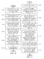
- FIG. 9 an illustration of a process for dynamically selecting weather bands is depicted in accordance with an advantageous embodiment.
- the process in Figure 9 may be implemented by a component such as dynamic weather band selection system 400 in Figure 4 .
- the process in Figure 9 may occur during flight of an aircraft and/or while an aircraft is on the ground.
- the process begins by identifying a current and predicted flight trajectory for a first aircraft (operation 902), such as trajectory 421 in Figure 4 , for example.
- the process identifies weather information for a number of locations along the current and predicted flight trajectory (operation 904).
- the weather information may be identified using a number of weather sources such as, for example, without limitation, ground weather information 410, aircraft weather information 412, a second aircraft on the current and predicted flight trajectory, and/or any other suitable weather source.
- the process identifies a current phase of flight for the first aircraft (operation 906).
- the current phase of flight may include, for example, without limitation, on-ground, climbing, cruising, descending, and landing.
- the process selects a number of weather bands for the first aircraft based on the current and predicted flight trajectory, the weather information, and the current phase of flight (operation 908).
- the process calculates flight trajectory data for the current and predicted flight trajectory based on the number of weather bands selected (operation 910).
- the process then generates a weather band selection based on the flight trajectory data and the number of weather bands (operation 912), and returns to operation 902.
- the process depicted in Figure 9 may be a continual process of dynamically selecting weather bands in order to provide the most up-to-date weather information for a flight plan and/or trajectory.
- the process depicted in Figure 9 may be initiated by a request, such as request 408 or push 407 in Figure 4 , for example.
- the weather band selection generated in Figure 9 may be sent to a number of recipients, including, without limitation, an aircraft, an operation center, a ground system, an external recipient, and/or any other suitable recipient.
- FIG. 10 an illustration of a process for generating a weather band selection is depicted in accordance with an advantageous embodiment.
- the process in Figure 10 may be implemented by a component such as dynamic weather band selection system 400 in Figure 4 .
- the process in Figure 10 may occur during flight of an aircraft and/or while an aircraft is on the ground.
- the process begins by receiving a request for a weather band selection for a flight plan (operation 1002).
- the flight plan may be received through a request, such as request 408 in Figure 4 , or through an information push, such as push 407 in Figure 4 .
- the process identifies weather information for the flight plan (operation 1004).
- the process identifies a weather forecast for the flight plan (operation 1006).
- the process receives current weather observation information for the flight plan (operation 1008).
- the process then identifies an aircraft type and aircraft state data for an aircraft associated with the flight plan (operation 1010).
- Aircraft state data may include, for example, without limitation, climbing, cruising, and descending.
- the process selects a number of weather bands for the flight plan based on the weather information, aircraft type, and aircraft state data to form a weather band selection (operation 1012).
- the number of weather bands may include weather information, such as, without limitation, altitude, temperature, atmospheric pressure, wind speed, wind direction, anti-thermal icing, and turbulence, for example.
- the process outputs the weather band selection (operation 1014) with the process terminating thereafter.
- the weather band selection may be outputted to a number of recipients, including, without limitation, an aircraft, an operation center, a ground system, an external recipient, and/or any other suitable recipient.
- FIG. 11 an illustration of a process for selecting weather bands is depicted in accordance with an advantageous embodiment.
- the process in Figure 11 may be implemented by a component such as dynamic weather band selection system 400 in Figure 4 .
- the process in Figure 11 may occur during flight of an aircraft and/or while an aircraft is on the ground.
- the process begins by receiving a flight plan (operation 1102).
- the process calculates an initial predicted trajectory having a number of waypoints for the flight plan (operation 1104).
- the number of waypoints may be, for example, waypoint 706 and waypoint 708 of Figure 7 .
- the process then identifies current and forecasted weather information associated with the number of waypoints (operation 1106).
- the process identifies aircraft state data and aircraft observed weather information for an aircraft currently on the flight plan (operation 1108).
- the process recalculates the initial predicted trajectory using the current and forecasted weather information and the aircraft observed weather information to form an updated trajectory (operation 1110).
- the process identifies weather information for the updated trajectory (operation 1112).
- the process selects a number of weather bands for the updated trajectory to form a weather band selection (operation 1114), with the process terminating thereafter.
- each block in the flowchart or block diagrams may represent a module, segment, function, and/or a portion of an operation or step.
- the function or functions noted in the block may occur out of the order noted in the figures.
- two blocks shown in succession may be executed substantially concurrently, or the blocks may sometimes be executed in the reverse order, depending upon the functionality involved.
- other blocks may be added in addition to the illustrated blocks in a flowchart or block diagram.
- the different advantageous embodiments provide a system comprising a weather band selection process and a processor unit.
- the processor unit is configured to run the weather band selection process.
- the weather band selection process identifies a flight plan associated with an aircraft, identifies weather information for the flight plan, and identifies a weather band selection for the aircraft using the flight plan and the weather information.
- the different advantageous embodiments provide a system that selects pertinent and relevant weather bands for a specific flight plan or trajectory.
- the weather band selection is therefore more accurate and up-to-date than preflight selections or default selections. This increases the efficiency of flight operations and the accuracy of flight trajectory calculations and calculation predictions when a flight plan is modified. More efficient flight operations result in a decrease of fuel consumption and environmental emissions.
- the different advantageous embodiments can take the form of an entirely hardware embodiment, an entirely software embodiment, or an embodiment containing both hardware and software elements.
- Some embodiments are implemented in software, which includes but is not limited to forms, such as, for example, firmware, resident software, and microcode.
- the different embodiments can take the form of a computer program product accessible from a computer-usable or computer-readable medium providing program code for use by or in connection with a computer or any device or system that executes instructions.
- a computer-usable or computer readable medium can generally be any tangible apparatus that can contain, store, communicate, propagate, or transport the program for use by or in connection with the instruction execution system, apparatus, or device.
- the computer usable or computer readable medium can be, for example, without limitation an electronic, magnetic, optical, electromagnetic, infrared, or semiconductor system, or a propagation medium.
- a computer-readable medium include a semiconductor or solid state memory, magnetic tape, a removable computer diskette, a random access memory (RAM), a read-only memory (ROM), a rigid magnetic disk, and an optical disk.
- Optical disks may include compact disk - read only memory (CD-ROM), compact disk - read/write (CD-R/W) and DVD.
- a computer-usable or computer-readable medium may contain or store a computer readable or usable program code such that when the computer readable or usable program code is executed on a computer, the execution of this computer readable or usable program code causes the computer to transmit another computer readable or usable program code over a communications link.
- This communications link may use a medium that is, for example without limitation, physical or wireless.
- a data processing system suitable for storing and/or executing computer readable or computer usable program code will include one or more processors coupled directly or indirectly to memory elements through a communications fabric, such as a system bus.
- the memory elements may include local memory employed during actual execution of the program code, bulk storage, and cache memories which provide temporary storage of at least some computer readable or computer usable program code to reduce the number of times code may be retrieved from bulk storage during execution of the code.
- I/O devices can be coupled to the system either directly or through intervening I/O controllers. These devices may include, for example, without limitation to keyboards, touch screen displays, and pointing devices. Different communications adapters may also be coupled to the system to enable the data processing system to become coupled to other data processing systems or remote printers or storage devices through intervening private or public networks. Nonlimiting examples are modems and network adapters are just a few of the currently available types of communications adapters.
Abstract
Description
- This application is related to commonly assigned and co-pending
U.S. Patent Application Serial No. 12/547,809 entitled "Dynamic Environmental Information Transmission". - The present disclosure relates generally aircraft and in particular to a method and apparatus for providing weather information for a trajectory of an aircraft. Still more particularly, the present disclosure relates to a method and apparatus for providing dynamically selecting three or four dimensional weather information for use in planning and updating flight trajectories.
- Weather information is used both during the planning and execution of flight operations. Planning flight operations results in the creation of flight plans. Flight plans are used to document basic information such as departure and arrival points, estimated time en route, various waypoints the aircraft must traverse en route, information pertaining to those waypoints, such as altitude and speed, information relating to legs of the flight between those waypoints, and aircraft predicted performance. This type of flight plan may be used to construct a flight trajectory including the various legs of the flight, which are connected to the various waypoints along the route. This flight trajectory may include a lateral trajectory defined in the horizontal plane and a vertical trajectory defined in the vertical plane.
- Weather information for the route between the departure and arrival points, including information about forecasted weather for the various waypoints along the route, may affect a flight trajectory. For example, if incorrect weather is forecasted for a particular waypoint along the route of the flight plan, certain predictions for the flight path may become inaccurate, such as speed, fuel consumption, and time en route.
- Additionally, revision of a flight plan may include deleting or adding waypoints, modifying the position of waypoints, or modifying the characteristics pertaining to the waypoints or legs between the waypoints, characteristics such as speed, time, or altitude, for example. The characteristics for various waypoints or legs between waypoints may include weather bands. A weather band is a collection of weather information for a specific geospatial point, such as a specific altitude or a specific three or four dimensional point in space. Weather information may include factors such as temperature, pressure, humidity, turbulence, wind speed, and wind direction.
- Ground operation centers may identify and send weather bands to an aircraft for use in determining how weather may affect flight trajectory calculations. The weather bands identified may be based on current or predicted weather or flight plans, or may be default weather bands non-specific to a particular flight trajectory. Often, actual weather may impact a flight trajectory where the actual weather differs from the predicted weather used to calculate the predicted flight trajectory. Additionally, different factors en route may cause an aircrew to modify the flight plan and the weather information from the ground operation center, loaded during preflight, may no longer be accurate or up-to-date for the modified flight plan. Inaccurate or dated weather information can result in inefficiencies for flight operations, such as an increase in fuel consumption and emissions or delay in flight time, for example.
- Therefore, it would be advantageous to have a method and apparatus that overcomes one or more of the issues described above as well as possibly other issues.
- One or more of the different advantageous embodiments provide a system comprising a weather band selection process and a processor unit. The processor unit is configured to run the weather band selection process. The weather band selection process identifies a flight trajectory associated with an aircraft, identifies current aircraft state data, identifies weather information for the flight trajectory, and identifies a weather band selection for the aircraft using the flight trajectory and the weather information.
- One or more of the different advantageous embodiments may further provide a method for generating a weather band selection. In response to receiving a request for a weather band selection for a flight plan, weather information is identified for the flight plan. A number of weather bands is selected for the flight plan based on the weather information to form a weather band selection. The weather band selection is outputted.
- One or more of the different advantageous embodiments may further provide a method for selecting weather bands. A current and predicted flight trajectory is identified for a first aircraft. Weather information is identified for a number of locations along the current and predicted flight trajectory. A number of weather bands is selected for the first aircraft based on the current and predicted flight trajectory and the weather information.
- The features, functions, and advantages can be achieved independently in various embodiments of the present disclosure or may be combined in yet other embodiments in which further details can be seen with reference to the following description and drawings.
- The novel features believed characteristic of the advantageous embodiments are set forth in the appended claims. The advantageous embodiments, however, as well as a preferred mode of use, further objectives and advantages thereof, will best be understood by reference to the following detailed description of an advantageous embodiment of the present disclosure when read in conjunction with the accompanying drawings, wherein:
-
Figure 1 is a pictorial representation of a network of data processing systems in which the advantageous embodiments of the present invention may be implemented; -
Figure 2 is an illustration of a data processing system in accordance with an advantageous embodiment; -
Figure 3 is an illustration of a weather selection environment in accordance with an advantageous embodiment; -
Figure 4 is an illustration of a dynamic weather band selection in accordance with an advantageous embodiment; -
Figure 5 is an illustration of a flight trajectory in accordance with an advantageous embodiment; -
Figure 6 is an illustration of a weather band in accordance with an advantageous embodiment; -
Figure 7 is an illustration of a weather band selection in accordance with an advantageous embodiment; -
Figure 8 is an illustration of a weather band selection in accordance with an advantageous embodiment; -
Figure 9 is an illustration of a process for dynamically selecting weather bands in accordance with an advantageous embodiment; -
Figure 10 is an illustration of a process for generating a weather band selection in accordance with an advantageous embodiment; and -
Figure 11 is an illustration of a process for selecting weather bands in accordance with an advantageous embodiment. - With reference now to the figures and in particular with reference to
Figures 1-2 , exemplary diagrams of data processing environments are provided in which the advantageous embodiments of the present invention may be implemented. It should be appreciated thatFigures 1-2 are only exemplary and are not intended to assert or imply any limitation with regard to the environments in which different embodiments may be implemented. Many modifications to the depicted environments may be made. - With reference now to the figures,
Figure 1 depicts a pictorial representation of a network of data processing systems in which the advantageous embodiments of the present invention may be implemented. Networkdata processing system 100 is a network of computers in which embodiments may be implemented. Networkdata processing system 100 containsnetwork 102, which is the medium used to provide communications links between various devices and computers connected together within networkdata processing system 100. Network 102 may include connections, such as wire, wireless communication links, or fiber optic cables.
In the depicted example,server 104 andserver 106 connect tonetwork 102 along withstorage unit 108. In addition,clients network 102. Theseclients server 104 provides data, such as boot files, operating system images, and applications toclients Clients Aircraft 116 also is a client that may exchange information withclients Aircraft 116 also may exchange information withservers Aircraft 116 may exchange data with different computers through a wireless communications link while in-flight or any other type of communications link while on the ground. In these examples,server 104,server 106,client 110,client 112, andclient 114 may be computers. Networkdata processing system 100 may include additional servers, clients, and other devices not shown. - In the depicted example, network
data processing system 100 is the Internet withnetwork 102 representing a worldwide collection of networks and gateways that use the Transmission Control Protocol/Internet Protocol (TCP/IP) suite of protocols to communicate with one another. Of course, networkdata processing system 100 also may be implemented as a number of different types of networks, such as for example, an intranet, a local area network (LAN), or a wide area network (WAN).Figure 1 is intended as an example, and not as an architectural limitation for different embodiments. - Turning now to
Figure 2 , a block diagram of a data processing system is depicted in accordance with an advantageous embodiment.Data processing system 200 is an example of a data processing system that may be used to implement servers and clients, such asserver 104 andclient 110. Further,data processing system 200 is an example of a data processing system that may be found inaircraft 116 inFigure 1 . - In this illustrative example,
data processing system 200 includescommunications fabric 202, which provides communications betweenprocessor unit 204,memory 206,persistent storage 208,communications unit 210, input/output (I/O)unit 212, anddisplay 214. -
Processor unit 204 serves to execute instructions for software that may be loaded intomemory 206.Processor unit 204 may be a set of one or more processors or may be a multi-processor core, depending on the particular implementation. Further,processor unit 204 may be implemented using one or more heterogeneous processor systems in which a main processor is present with secondary processors on a single chip. As another illustrative example,processor unit 204 may be a symmetric multi-processor system containing multiple processors of the same type. -
Memory 206 andpersistent storage 208 are examples ofstorage devices 216. A storage device is any piece of hardware that is capable of storing information, such as, for example without limitation, data, program code in functional form, and/or other suitable information either on a temporary basis and/or a permanent basis.Memory 206, in these examples, may be, for example, a random access memory or any other suitable volatile or non-volatile storage device.Persistent storage 208 may take various forms depending on the particular implementation. For example,persistent storage 208 may contain one or more components or devices. For example,persistent storage 208 may be a hard drive, a flash memory, a rewritable optical disk, a rewritable magnetic tape, or some combination of the above. The media used bypersistent storage 208 also may be removable. For example, a removable hard drive may be used forpersistent storage 208. -
Communications unit 210, in these examples, provides for communications with other data processing systems or devices. In these examples,communications unit 210 is a network interface card.Communications unit 210 may provide communications through the use of either or both physical and wireless communications links. - Input/
output unit 212 allows for input and output of data with other devices that may be connected todata processing system 200. For example, input/output unit 212 may provide a connection for user input through a keyboard, a mouse, and/or some other suitable input device. Further, input/output unit 212 may send output to a printer.Display 214 provides a mechanism to display information to a user. - Instructions for the operating system, applications and/or programs may be located in
storage devices 216, which are in communication withprocessor unit 204 throughcommunications fabric 202. In these illustrative examples the instruction are in a functional form onpersistent storage 208. These instructions may be loaded intomemory 206 for execution byprocessor unit 204. The processes of the different embodiments may be performed byprocessor unit 204 using computer implemented instructions, which may be located in a memory, such asmemory 206. - These instructions are referred to as program code, computer usable program code, or computer readable program code that may be read and executed by a processor in
processor unit 204. The program code in the different embodiments may be embodied on different physical or tangible computer readable media, such asmemory 206 orpersistent storage 208. -
Program code 218 is located in a functional form on computerreadable media 220 that is selectively removable and may be loaded onto or transferred todata processing system 200 for execution byprocessor unit 204.Program code 218 and computerreadable media 220 formcomputer program product 222 in these examples. In one example, computerreadable media 220 may be in a tangible form, such as, for example, an optical or magnetic disc that is inserted or placed into a drive or other device that is part ofpersistent storage 208 for transfer onto a storage device, such as a hard drive that is part ofpersistent storage 208. In a tangible form, computerreadable media 218 also may take the form of a persistent storage, such as a hard drive, a thumb drive, or a flash memory that is connected todata processing system 200. The tangible form of computerreadable media 218 is also referred to as computer recordable storage media. In some instances, computerreadable media 220 may not be removable. - Alternatively,
program code 218 may be transferred todata processing system 200 from computerreadable media 218 through a communications link tocommunications unit 210 and/or through a connection to input/output unit 212. The communications link and/or the connection may be physical or wireless in the illustrative examples. The computer readable media also may take the form of non-tangible media, such as communications links or wireless transmissions containing the program code. - In some illustrative embodiments,
program code 218 may be downloaded over a network topersistent storage 208 from another device or data processing system for use withindata processing system 200. For instance, program code stored in a computer readable storage medium in a server data processing system may be downloaded over a network from the server todata processing system 200. The data processing system providingprogram code 218 may be a server computer, a client computer, or some other device capable of storing and transmittingprogram code 218. - The different components illustrated for
data processing system 200 are not meant to provide architectural limitations to the manner in which different embodiments may be implemented. The different illustrative embodiments may be implemented in a data processing system including components in addition to or in place of those illustrated fordata processing system 200. Other components shown inFigure 2 can be varied from the illustrative examples shown. The different embodiments may be implemented using any hardware device or system capable of executing program code. As one example, the data processing system may include organic components integrated with inorganic components and/or may be comprised entirely of organic components excluding a human being. For example, a storage device may be comprised of an organic semiconductor. - As another example, a storage device in
data processing system 200 is any hardware apparatus that may store data.Memory 206,persistent storage 208 and computerreadable media 220 are examples of storage devices in a tangible form. - In another example, a bus system may be used to implement
communications fabric 202 and may be comprised of one or more buses, such as a system bus or an input/output bus. Of course, the bus system may be implemented using any suitable type of architecture that provides for a transfer of data between different components or devices attached to the bus system. Additionally, a communications unit may include one or more devices used to transmit and receive data, such as a modem or a network adapter. Further, a memory may be, for example,memory 206 or a cache such as found in an interface and memory controller hub that may be present incommunications fabric 202. - The different advantageous embodiments recognize and take into account a number of different considerations. For example, the different advantageous embodiments recognize and take into account that currently used systems select default weather bands for an aircraft to use for flight trajectory calculations. These systems do not select dynamic weather bands. An example of a default weather band may be a selection of weather information for three different altitudes above a static location, such as an aircraft operation center for example. When default weather bands are selected, the same default altitudes are always chosen regardless of the surrounding circumstances. Even when default weather bands are selected, current methods increase inefficiencies in the flight trajectory calculations if the weather is out of date, not entered into a flight management computer, or provided at the wrong time. Additionally, current systems and methods do not consider the impact of environmental factors or aircraft events when choosing weather bands. Rather, current methods only consider winds at the chosen default altitudes, which can cause the aircraft to calculate undesired top-of-climb, top-of-descent, step climbs, or deceleration and acceleration points, for example.
- The different advantageous embodiments further recognize and take into account that weather solutions for aircrew selected trajectory points may be requested during flight. An aircrew may desire weather solutions at waypoints along a secondary, alternative, or modified flight plan. Current systems also do not provide an opportunity to view current observed or forecasted weather before executing a flight plan modification for the aircrew. Rather, aircrews rely on human interpolation and manual entry for a flight plan modification, which may lead to data entry errors or less than optimized data entry.
- The different advantageous embodiments further recognize and take into account that even in the rare cases where updated weather information is available, neither the aircrew nor the ground crew know which altitudes are pertinent to the flight trajectory for the aircraft. This lack of information increases inefficiencies in calculating changes to flight trajectories in a flight plan. As a result, currently used methods involve the selection of default altitudes regardless of the actual wind effects at different altitudes, if a selection is made at all.
- The different advantageous embodiments recognize and take into account that it would be useful to have a method and apparatus for providing dynamic weather information. As an example, an identification of a number of weather bands for flight trajectory is desirable. A number, when referring to items, means one or more items. For example, a number of weather bands is one or more weather bands. Identifying a number of weather bands that are relevant to a flight plan and/or trajectory for an aircraft may provide for more accurate and efficient planning in operating the aircraft.
- Thus, one or more of the different advantageous embodiments may provide a system comprising a weather band selection process and a processor unit. The processor unit is configured to run the weather band selection process. The weather band selection process identifies a flight trajectory associated with an aircraft, identifies weather information for the flight trajectory, and identifies a weather band selection for the aircraft using the flight trajectory, aircraft information and the weather information.
- One or more of the different advantageous embodiments may further provide a method for generating a weather band selection. In response to receiving a request for a weather band selection for a flight plan, weather information is identified for the flight plan. A number of weather bands is selected for the flight plan based on the weather information to form a weather band selection. The weather band selection is outputted.
- One or more of the different advantageous embodiments may further provide a method for selecting weather bands. A current and predicted flight trajectory is identified for a first aircraft. Weather information is identified for a number of locations along the current and predicted flight trajectory. A number of weather bands is selected for the first aircraft based on the current and predicted flight trajectory and the weather information.
- With reference now to
Figure 3 , an illustration of a weather selection environment is depicted in accordance with an advantageous embodiment. Weather selection environment 300 may be implemented in an environment such asnetwork 102 inFigure 1 . - Weather selection environment 300 includes number of
other ground systems 301, number of operation centers 302, number ofaircraft 304, andweather selection system 306. Number of operation centers 302 may include airline operation centers at various locations, and/or any other type of operation centers. Number of operation centers 302 includescomputer system 303 andoperation personnel 308.Computer system 303 may include a number of computers. As used herein, a number refers to one or more computers. The number of computers ofcomputer system 303 may be networked in an environment such asnetwork 102 inFigure 1 . Number ofaircraft 304 may be any type of aircraft including, without limitation, jet engine aircraft, twin engine aircraft, single engine aircraft, spacecraft, and/or any other suitable type of aircraft.Aircraft 305 may be an example of one implementation of number ofaircraft 304.Aircraft 305 includescomputer system 309 andaircrew 310.Computer system 309 may include a number of computers. The number of computers ofcomputer system 303 may be networked in an environment such asnetwork 102 inFigure 1 . Number ofother ground systems 301 may include, without limitation, weather reporting stations, weather monitoring stations, and/or any other suitable ground system. - In one advantageous embodiment,
computer system 303 may also includetrajectory calculation process 307.Trajectory calculation process 307 may be used to predict a trajectory for flight plan of an aircraft, such asaircraft 305, and send the trajectory to the aircraft. In another advantageous embodiment,computer system 309 ofaircraft 305 includestrajectory calculation process 311.Trajectory calculation process 311 may be used to predict a trajectory ofaircraft 305 using information received fromweather selection system 306. - In one advantageous embodiment,
weather selection system 306 is located in a remote location from number of operation centers 302 and number ofaircraft 304. In this exampleweather selection system 306 may be operated by a third party service.Weather selection system 306 usescommunications unit 312 to interact with number ofoperations centers 302 and number ofaircraft 304.Weather selection system 306 may be implemented using one or more ofdata processing system 200. -
Communications unit 312, in these examples, provides for communications with other data processing systems or devices. In these examples,communications unit 312 may be a network interface card.Communications unit 312 may provide communications through the use of either or both physical and wireless communications links.Communications unit 312 may be integrated withprocessor 314 and/or may be independent from and accessible toprocessor 314. -
Processor 314 and/orcommunications unit 312 may access number ofdatabases 316. Number ofdatabases 316 may include various databases with information such as, ground weather, aircraft weather, aircraft state data, aircraft predictions, aircraft model identification, flight plans, and/or any other suitable information.Processor 314 may receiveweather information 318. In one advantageous embodiment,weather information 318 may be accessed using number ofdatabases 316. In another advantageous embodiment,weather information 318 may be received from number of operation centers 302, number ofaircraft 304,aircraft 305, and/or number ofother ground systems 301. In an illustrative example,operation personnel 308 of number of operation centers 302 may send updatedweather information 318 toweather selection system 306. In another illustrative example,aircrew 310 ofaircraft 305 may send observedweather information 318 toweather selection system 306. In yet another illustrative example,weather information 317 from number ofother ground systems 301 may be transmitted to and/or retrieved byweather selection system 306 usingcomputer system 315.Computer system 315 may be an example of one implementation ofdata processing system 200 inFigure 2 , for example. -
Processor 314 includes weatherband selection process 320. Weatherband selection process 320 usesweather information 318 to generateweather band selection 322.Weather band selection 322 may then be sent to number of operation centers 302 and/or number ofaircraft 304. - The illustration of weather selection environment 300 in
Figure 3 is not meant to imply physical or architectural limitations to the manner in which different advantageous embodiments may be implemented. Other components in addition to and/or in place of the ones illustrated may be used. Some components may be unnecessary in some advantageous embodiments. Also, the blocks are presented to illustrate some functional components. One or more of these blocks may be combined and/or divided into different blocks when implemented in different advantageous embodiments. - For example, in one advantageous embodiment,
communications unit 312 may be integrated withprocessor 314 in a manner illustrated byFigure 2 . In another advantageous embodiment,weather selection system 306 may be distributed across or located in at least one of a remote location, number of operation centers 302, and/or number ofaircraft 304. As used herein, the phrase "at least one of", when used with a list of items, means that different combinations of one or more of the listed items may be used and only one of each item in the list may be needed. For example, "at least one of item A, item B, and item C" may include, for example, without limitation, item A or item A and item B. This example also may include item A, item B, and item C or item B and item C. - Turning now to
Figure 4 , an illustration of a weather band selection system is depicted in accordance with an advantageous embodiment. Dynamic weatherband selection system 400 is an illustrative example of one implementation ofweather selection system 306 inFigure 3 . Dynamic weatherband selection system 400 may be implemented using a data processing system, such asdata processing system 200 inFigure 2 . - Dynamic weather
band selection system 400 includes dynamicweather band processor 402. Dynamicweather band processor 402 is configured to choose climb, cruise, and descent weather that are specific to a particular flight trajectory. The dynamic weather bands and weather information are chosen based on aircraft type, on-board equipage, current and forecasted weather, flight plan, phase of flight, aircraft events, aircraft state data, and the computed trajectory for the flight plan. Phase of flight may include, for example, without limitation, on-ground, climbing, cruising, descending, landing, and/or any other suitable phase of flight. Aircraft events may include, for example, without limitation, gear extension, gear retraction, flap extension, flap retraction, step climb points, step down points, and/or any other suitable aircraft event where there are changes in aircraft pitch, speed, and/or thrust. - In these illustrative examples, dynamic
weather band processor 402 continually evaluates information received in order to dynamically select weather for a flight plan. In other illustrative examples, dynamicweather band processor 402 may be triggered to evaluate information byrequest 408, push 407, or some other event to dynamically select weather bands for a particular flight plan.Request 408 may be initiated by either aircraft initiatedweather request 404 or ground initiatedrequest 406.Request 408 may include a specific flight plan used by dynamicweather band processor 402 to dynamically select weather bands for the specific flight plan in response to request 408, for example. Push 407 may be an automatic push of a flight plan to dynamicweather band processor 402 to calculate a new weather solution before any request is made by an aircraft. - As additional illustrative examples, the event may be, for example, without limitation, receipt of updated weather information, a change in a flight plan, or some other suitable event.
- Dynamic
weather band processor 402 may receive information from a number of databases, such asground weather information 410,aircraft weather information 412, aircraftcurrent state data 416, andaircraft predictions 418.Ground weather information 410,aircraft weather information 412, aircraftcurrent state data 416, andaircraft predictions 418 may be illustrative examples of one implementation of number ofdatabases 316 inFigure 3 . Dynamicweather band processor 402 may also receive information directly from a number of aircraft and/or operation centers, such asaircraft 403 andoperation center 405, for example. -
Ground weather information 410 may include information collected from weather sources, such as, for example, without limitation, National Oceanic and Atmospheric Administration (NOAA).Ground weather information 410 may also include information about weather local to a particular operation center, forecasted weather information for a number of locations, and/or any other suitable type of ground weather information.Operation center 405 may be an illustrative example of one implementation of an operation center that sends weather information to groundweather information 410. -
Aircraft weather information 412 may include weather directly reported or derived from a number of aircraft, such as number ofaircraft 304 inFigure 3 , for example.Aircraft 403 may be an illustrative example of one implementation of an aircraft that directly sends currently observed weather information toaircraft weather information 412.Aircraft weather information 412 may include information such as, without limitation, temperature, pressure, turbulence, icing, wind speed, wind direction, wind vertical acceleration, and/or any other suitable information pertaining to a number of different points for a particular flight path and/or trajectory. - Dynamic
weather band processor 402 may receiveweather information 414 from a number of different sources, including, without limitation,ground weather information 410,aircraft weather information 412,aircraft 403,operation center 405, and/or any other suitable weather source. Dynamicweather band processor 402 is configured to evaluateweather information 414 when dynamically selecting weather bands for a particular flight plan and/or flight trajectory, for example. - Aircraft
current state data 416 includes information pertaining to a number of aircraft, such as number ofaircraft 304 inFigure 3 . Aircraftcurrent state data 416 may include a number of unique identifiers for the number of aircraft, such as tail numbers for example. Aircraftcurrent state data 416 may identify a particular aircraft and include current state information about that particular aircraft, such as, without limitation, on-ground, climbing, cruising, descending, altitude, heading, weight, center of gravity, speed, and/or any other suitable state data. -
Aircraft predictions 418 may include a number of flight plans and associated predictions for the trajectory and weather of an aircraft based on each of the number of trajectories associated with the number of flight plans.Aircraft predictions 418 includes aircraft state data predictions associated with a number of points in time based on predicted weather, flight plan, weight of aircraft, aircraft configuration, and/or any other suitable information.Aircraft predictions 418 may include number oftrajectories 419. Number oftrajectories 419 are flight trajectories calculated from flight path information provided from either an aircraft or ground source. Number oftrajectories 419 are calculated from the flight path information using flight path restrictions, such as altitude, speed, and/or time, and planned flight events, such as gear extension, for example. - Dynamic
weather band processor 402 gathersinformation 420 for evaluation fromground weather information 410,aircraft weather information 412, aircraftcurrent state data 416, andaircraft predictions 418. Dynamicweather band processor 402 passes the gatheredinformation 420 through data filtering 422.Data filtering 422 is a filtering process that filtersinformation 420 before passing filteredweather information 424 toselection module 426.Data filtering 422 andselection module 426 are illustrative examples of one implementation of weatherband selection process 320 inFigure 3 .Data filtering 422 may include, for example, without limitation,aircraft biases 428 andaircraft state 430. -
Data filtering 422 may filterinformation 420 based on factors such as, without limitation, where the information is coming from, what an aircraft was doing when the information was collected, system inconsistencies specific to particular aircraft, time of information transmission, aircraft speed, current aircraft altitude, current aircraft heading, current aircraft phase of flight, current aircraft state data, and/or any other type of factor.Aircraft biases 428 may reduce or increase the raw information received based on the factors considered.Aircraft state 430 may determine whether or not to use information received based on the factors considered. For example, certain types of aircraft movement may distort measurements.Aircraft state 430 may determine whether the state of an aircraft, such asaircraft 403, at the time information was obtained would invalidate the accuracy of the information. In one illustrative example, an aircraft in a turn, climb, or descent may affect certain parameters of information detections because of sensor position during those maneuvers. An example of a parameter that may be affected may be, without limitation, air pressure, which may in turn affect the accuracy of wind information. In this example, air pressure may be incorrectly measured, or sensed, due to a reduction or increase in airflow. An inaccurate air pressure measurement may result in an inaccurate airspeed measurement, which may lead to inaccurate wind information, for example.Aircraft state 430 analyzes the state of the aircraft at the time information was obtained to determine the integrity of the information. -
Filtered information 424 may be sent from data filtering 422 toselection module 426.Selection module 426 processes filteredinformation 424 and appliesselection criteria 427 to an aircraft trajectory received. In an illustrative example,trajectory 421 may be received ininformation 420 from number oftrajectories 419 inaircraft predictions 418.Selection module 426 usesselection criteria 427 to determine the weather information pertinent totrajectory 421.Selection criteria 427 may include, without limitation,trajectory prediction 432,atmospheric pressures 434,temperatures 436,humidity 438,wind 440,events 442, and number of recipients 444.Selection module 426 usestrajectory prediction 432 to predict howtrajectory 421 may change from its flight plan based onweather information 414 received in filteredinformation 424. -
Events 442 are points along an aircraft trajectory where there are changes in aircraft pitch, speed, and/or thrust.Events 442 may include, for example, without limitation, flap extension, flap retraction, landing gear extension, landing gear retraction, deceleration and/or acceleration points to meet a time restriction, altitude restriction, and/or speed restriction, thermal anti-icing, step climb points, step down points, and/or any other suitable events that may affecttrajectory 421. -
Selection module 426 dynamically selects weather bands based onselection criteria 427 associated withrequest 408 or push 407 to form weather bands selected 452. Weather bands selected 452 may include a number of altitude weather bands ranked in order of importance and/or impact to the trajectory being considered fromrequest 408. Weather bands selected 452 is then sent tooutput process 454. Dynamicweather band processor 402 usesoutput process 454 to determine how and where selectedweather bands 452 should be sent.Output process 454 determines the recipient of weather bands selected 452 and formats weather bands selected 452 based on the recipient.Output process 454 may identify a number of data formats capable of being received by a particular recipient, such asaircraft 403 oroperation center 405 for example. As used herein, a number of data formats refers to one or more data formats. - In one illustrative example,
aircraft 403 may be able to receive weather bands selected 452 in any combination of data formats. The data formats may be, for example, without limitation, freetext, standard aircraft communications addressing and reporting system (ACARS) messaging, and/or any other suitable data format. In another illustrative example,aircraft 403 may only be able to receive weather bands selected 452 in one specific data format compatible with systems ofaircraft 403. In still another illustrative example, weather bands selected 452 may be sent in a specific data format preferred byoperation center 405. - Selected
weather bands 452 may be sent to any and/or all ofground station 456,aircraft 458, or additionalexternal recipient 460. Additionalexternal recipient 460 may be, without limitation, an air navigation service provider or other qualified subscriber, for example. In one illustrative example, selectedweather bands 452 may be formatted for transmission toaircraft 458, and sent as weather uplink toaircraft 462. In another illustrative example, selectedweather bands 452 may be formatted for transmission toground station 456, and sent as weather message toground 464. - The illustration of dynamic weather
band selection system 400 inFigure 4 is not meant to imply physical or architectural limitations to the manner in which different advantageous embodiments may be implemented. Other components in addition to and/or in place of the ones illustrated may be used. Some components may be unnecessary in some advantageous embodiments. Also, the blocks are presented to illustrate some functional components. One or more of these blocks may be combined and/or divided into different blocks when implemented in different advantageous embodiments. - For example, in one advantageous embodiment, a manual request may be initiated from any qualified subscriber of the weather band selection system. In another advantageous embodiment, manual and automatic triggers can be used to reinitialize the process given a new set of conditions. An example of this may be flight plan modifications. In this example, one weather solution may have been computed according to the initial flight path of an aircraft, but the aircrew or a subscriber desires to view the solution using a different flight path before executing that maneuver. A request may be sent with the new proposed flight plan and a new solution may be generated, in this illustrative example.
- With reference now to
Figure 5 , an illustration of a flight path is depicted in accordance with an advantageous embodiment.Flight plan 500 may be an illustrative example of one implementation of a flight path sent overrequest 408 inFigure 4 . -
Flight path 500 may includetrajectory 502.Aircraft 504 may travel alongtrajectory 502 earlier in time thanaircraft 506. During the time thataircraft 504 followstrajectory 502 offlight path 500,aircraft 504 may experience various weather factors at different points alongtrajectory 502, such aspoint 508,point 510,point 512, andpoint 514.Aircraft 504 andaircraft 506 may directly relay weather information at each ofpoints operation center 405 oraircraft weather information 412 inFigure 4 , for example. Weather information may include, for example, without limitation, temperature, atmospheric pressure, turbulence, wind speed, wind direction, the altitude at which the weather is detected, the phase of flight during which the weather is detected, and/or any other suitable information. - When
aircraft 506 followstrajectory 502 alongflight path 500 at a later time thanaircraft 504,aircraft 506 may receive the benefit of the weather information detected byaircraft 504 as well as the current weather detected byaircraft 506. The current weather detected byaircraft 506 may also be used to update the dated weather in the onboard computer ofaircraft 506. The dated weather may be, for example, the weather detected earlier in time byaircraft 504, and/or weather information uploaded preflight into the onboard computer ofaircraft 506. In an illustrative example,aircraft 506 may request weather band selections from a system, such as dynamic weatherband selection system 400 inFigure 4 . The system can access the most recently acquired weather information fortrajectory 502 to determine the weather information that is pertinent toaircraft 506. The information obtained byaircraft 504 alongtrajectory 502 may be used to anticipate theweather aircraft 506 will encounter onpoints trajectory 502 forflight path 500. Additionally, current weather detected byaircraft 506 alongtrajectory 502 may also be used to update onboard weather information and anticipate theweather aircraft 506 will encounter onupcoming points trajectory 502. - With reference now to
Figure 6 , an illustration of a weather band is depicted in accordance with an advantageous embodiment. Number ofweather bands 600 may be an example of weather bands selected 452 inFigure 4 . - Number of
weather bands 600 may includeweather band 602.Weather band 602 includes information such as, without limitation,altitude 604 andother information 606. Other information may include, without limitation, temperature, atmospheric pressure, anti-ice levels, wind speed, wind direction, and/or any other suitable information specific toaltitude 604. - The illustration of number of
weather bands 600 inFigure 6 is not meant to imply physical or architectural limitations to the manner in which different advantageous embodiments may be implemented. Other components in addition to and/or in place of the ones illustrated may be used. Some components may be unnecessary in some advantageous embodiments. Also, the blocks are presented to illustrate some functional components. One or more of these blocks may be combined and/or divided into different blocks when implemented in different advantageous embodiments. - For example, in some advantageous embodiments, number of
weather bands 600 may include one or more weather bands in addition toweather band 602. In this example, each weather band may include weather information specific to the altitude of that weather band, just asother information 606 is specific toaltitude 604 forweather band 602. As used herein, number refers to one or more weather bands. - With reference now to
Figure 7 , an illustration of a weather band selection is depicted in accordance with an advantageous embodiment.Weather band selection 700 may be an illustrative example of one implementation of weather uplink toaircraft 462 from dynamic weatherband selection system 400 inFigure 4 . -
Weather band selection 700 is associated withtrajectory 701.Trajectory 701 may have a number of associated waypoints for which weather information may be dynamically selected.Weather band selection 700 may have a number of associated weather bands, for example,weather band 702 andweather band 704.Weather band 702 may include weather information specific towaypoint 706.Weather band 704 may include weather information specific towaypoint 708. The weather information specific towaypoint 706 may include, for example, without limitation,altitude 710,temperature 712,wind direction 714,wind speed 716, and/or any other weather information forwaypoint 706. The weather information specific towaypoint 708 may include, for example, without limitation,altitude 718,temperature 720,wind direction 722,wind speed 724, and/or any other weather information forwaypoint 708. -
Altitudes waypoints waypoint 706 may be at an altitude of 15,000 feet, whilewaypoint 708 may be at an altitude of 10,000 feet.Weather band selection 700 may be an illustrative example of a weather band selection for a cruise time phase of flight of a particular flight plan. The weather information provided byweather band selection 700 may be assessed along the known and intendedtrajectory 701 for the flight plan to determine the impact of the weather ontrajectory 701, for example. - The illustration of
weather band selection 700 inFigure 7 is not meant to imply physical or architectural limitations to the manner in which different advantageous embodiments may be implemented. Other components in addition to and/or in place of the ones illustrated may be used. Some components may be unnecessary in some advantageous embodiments. Also, the blocks are presented to illustrate some functional components. One or more of these blocks may be combined and/or divided into different blocks when implemented in different advantageous embodiments. - For example, in some advantageous embodiments, if a flight phase for an aircraft is determined the weather
band selection system 400 to be enroute cruise, both cruise winds, as illustrated byweather band selection 700, and descent winds, as illustrated byweather band selection 800, may be provided to the aircraft alongtrajectory 701. In another advantageous embodiment, if a flight phase of climb is determined for an aircraft, both climb winds and cruise winds may be provided in a weather band selection. - With reference now to
Figure 8 , an illustration of a weather band selection is depicted in accordance with an advantageous embodiment.Weather band selection 800 may be an illustrative example of one implementation of weather uplink toaircraft 462 from dynamic weatherband selection system 400 inFigure 4 . -
Weather band selection 800 depicts a weather band selection fortrajectory 801.Weather band Weather band selection 800 may also includeother information 803.Other information 803 may be weather information that is specific to a phase of flight rather than an altitude, altitude range, waypoint or specific weather band. Examples ofother information 803 may include, without limitation, thermal anti-icing for engine bleeds, temperature deviations from standard atmospheric temperatures, barometric pressure, and/or any other suitable information related to a phase of flight. -
Weather band 802 may include weather information specific toaltitude 810. The weather information foraltitude 810 may include, without limitation,temperature 812,wind direction 814,wind speed 816, and/or any other suitable weather information. -
Weather band 804 may include weather information specific toaltitude 818. The weather information foraltitude 818 may include, without limitation,temperature 820,wind direction 822,wind speed 824, and/or any other suitable weather information. -
Weather band 806 may include weather information specific toaltitude 826. The weather information foraltitude 826 may include, without limitation,temperature 828,wind direction 830,wind speed 832, and/or any other suitable weather information.Weather band 808 may include weather information specific toaltitude 834. The weather information foraltitude 834 may include, without limitation,temperature 836,wind direction 838,wind speed 840, and/or any other suitable weather information. - Each of
altitude 810,altitude 818,altitude 826, andaltitude 834 may be, for example, without limitation, a discrete altitude or an altitude range. In one illustrative example of discrete altitudes,altitude 810 may be 30,000 feet,altitude 818 may be 35,000 feet,altitude 826 may be 37,500 feet, andaltitude 834 may be 40,000 feet. In this example of discrete altitudes, each ofaltitudes altitudes altitude 810 andaltitude 818 may be an altitude range of 30,000 feet to 35,000 feet, in this example. Ifweather bands weather band selection 800, a range betweenaltitude 810 andaltitude 834 may be an altitude range of 30,000 feet to 40,000 feet, for example. In this advantageous embodiment, additional weather bands may provide for an increasingly broad range of overall altitudes for a weather band selection. - In another illustrative example of altitude ranges,
altitude 810 may represent 30,000-32,500 feet,altitude 818 may represent 32,500-35,000 feet,altitude 826 may represent 35,000-37,500 feet, andaltitude 834 may represent 37,500-40,000 feet. In this example, weather information associated withaltitude 810 may be information about weather occurring in the altitude range of 30,000-32,500 feet. Based on the weather associated with an altitude, or altitude range, an aircraft may change its vertical profile to avoid certain types of weather. Changing vertical profile may include, for example, ascending or descending from a current cruise altitude. - The illustration of
weather band selection 800 inFigure 8 is not meant to imply physical or architectural limitations to the manner in which different advantageous embodiments may be implemented. Other components in addition to and/or in place of the ones illustrated may be used. Some components may be unnecessary in some advantageous embodiments. Also, the blocks are presented to illustrate some functional components. One or more of these blocks may be combined and/or divided into different blocks when implemented in different advantageous embodiments. - For example, in some advantageous embodiments,
other information 803 may be implemented in combination withweather band 802,weather band 804,weather band 806, and/orweather band 808. - With reference now to
Figure 9 , an illustration of a process for dynamically selecting weather bands is depicted in accordance with an advantageous embodiment. The process inFigure 9 may be implemented by a component such as dynamic weatherband selection system 400 inFigure 4 . The process inFigure 9 may occur during flight of an aircraft and/or while an aircraft is on the ground. - The process begins by identifying a current and predicted flight trajectory for a first aircraft (operation 902), such as
trajectory 421 inFigure 4 , for example. The process identifies weather information for a number of locations along the current and predicted flight trajectory (operation 904). The weather information may be identified using a number of weather sources such as, for example, without limitation,ground weather information 410,aircraft weather information 412, a second aircraft on the current and predicted flight trajectory, and/or any other suitable weather source. The process identifies a current phase of flight for the first aircraft (operation 906). The current phase of flight may include, for example, without limitation, on-ground, climbing, cruising, descending, and landing. The process then selects a number of weather bands for the first aircraft based on the current and predicted flight trajectory, the weather information, and the current phase of flight (operation 908). The process calculates flight trajectory data for the current and predicted flight trajectory based on the number of weather bands selected (operation 910). The process then generates a weather band selection based on the flight trajectory data and the number of weather bands (operation 912), and returns tooperation 902. - The process depicted in
Figure 9 may be a continual process of dynamically selecting weather bands in order to provide the most up-to-date weather information for a flight plan and/or trajectory. In another advantageous embodiment, the process depicted inFigure 9 may be initiated by a request, such asrequest 408 or push 407 inFigure 4 , for example. The weather band selection generated inFigure 9 may be sent to a number of recipients, including, without limitation, an aircraft, an operation center, a ground system, an external recipient, and/or any other suitable recipient. - With reference now to
Figure 10 , an illustration of a process for generating a weather band selection is depicted in accordance with an advantageous embodiment. The process inFigure 10 may be implemented by a component such as dynamic weatherband selection system 400 inFigure 4 . The process inFigure 10 may occur during flight of an aircraft and/or while an aircraft is on the ground. - The process begins by receiving a request for a weather band selection for a flight plan (operation 1002). The flight plan may be received through a request, such as
request 408 inFigure 4 , or through an information push, such aspush 407 inFigure 4 . The process identifies weather information for the flight plan (operation 1004). The process then identifies a weather forecast for the flight plan (operation 1006). The process receives current weather observation information for the flight plan (operation 1008). The process then identifies an aircraft type and aircraft state data for an aircraft associated with the flight plan (operation 1010). Aircraft state data may include, for example, without limitation, climbing, cruising, and descending. The process selects a number of weather bands for the flight plan based on the weather information, aircraft type, and aircraft state data to form a weather band selection (operation 1012). The number of weather bands may include weather information, such as, without limitation, altitude, temperature, atmospheric pressure, wind speed, wind direction, anti-thermal icing, and turbulence, for example. Next, the process outputs the weather band selection (operation 1014) with the process terminating thereafter. The weather band selection may be outputted to a number of recipients, including, without limitation, an aircraft, an operation center, a ground system, an external recipient, and/or any other suitable recipient. - The illustration of the process for providing a weather selection in
Figure 10 is not meant to imply physical or architectural limitations to the manner in which different advantageous embodiments may be implemented. Other steps in addition to and/or in place of the ones illustrated may be used. Some steps may be unnecessary in some advantageous embodiments. Also, the different operations are presented to illustrate one example of a functional process. One or more of these operations may be combined and/or divided into different operations when implemented in different advantageous embodiments. Additionally, one or more of these operations may be performed in a different order than depicted in different advantageous embodiments. - With reference now to
Figure 11 , an illustration of a process for selecting weather bands is depicted in accordance with an advantageous embodiment. The process inFigure 11 may be implemented by a component such as dynamic weatherband selection system 400 inFigure 4 . The process inFigure 11 may occur during flight of an aircraft and/or while an aircraft is on the ground. - The process begins by receiving a flight plan (operation 1102). The process calculates an initial predicted trajectory having a number of waypoints for the flight plan (operation 1104). The number of waypoints may be, for example,
waypoint 706 andwaypoint 708 ofFigure 7 . The process then identifies current and forecasted weather information associated with the number of waypoints (operation 1106). The process identifies aircraft state data and aircraft observed weather information for an aircraft currently on the flight plan (operation 1108). Next, the process recalculates the initial predicted trajectory using the current and forecasted weather information and the aircraft observed weather information to form an updated trajectory (operation 1110). The process identifies weather information for the updated trajectory (operation 1112). The process then selects a number of weather bands for the updated trajectory to form a weather band selection (operation 1114), with the process terminating thereafter. - The flowcharts and block diagrams in the different depicted embodiments illustrate the architecture, functionality, and operation of some possible implementations of apparatus and methods in different advantageous embodiments. In this regard, each block in the flowchart or block diagrams may represent a module, segment, function, and/or a portion of an operation or step. In some alternative implementations, the function or functions noted in the block may occur out of the order noted in the figures. For example, in some cases, two blocks shown in succession may be executed substantially concurrently, or the blocks may sometimes be executed in the reverse order, depending upon the functionality involved. Also, other blocks may be added in addition to the illustrated blocks in a flowchart or block diagram.
- Thus, the different advantageous embodiments provide a system comprising a weather band selection process and a processor unit. The processor unit is configured to run the weather band selection process. The weather band selection process identifies a flight plan associated with an aircraft, identifies weather information for the flight plan, and identifies a weather band selection for the aircraft using the flight plan and the weather information.
- The different advantageous embodiments provide a system that selects pertinent and relevant weather bands for a specific flight plan or trajectory. The weather band selection is therefore more accurate and up-to-date than preflight selections or default selections. This increases the efficiency of flight operations and the accuracy of flight trajectory calculations and calculation predictions when a flight plan is modified. More efficient flight operations result in a decrease of fuel consumption and environmental emissions.
- The different advantageous embodiments can take the form of an entirely hardware embodiment, an entirely software embodiment, or an embodiment containing both hardware and software elements. Some embodiments are implemented in software, which includes but is not limited to forms, such as, for example, firmware, resident software, and microcode.
- Furthermore, the different embodiments can take the form of a computer program product accessible from a computer-usable or computer-readable medium providing program code for use by or in connection with a computer or any device or system that executes instructions. For the purposes of this disclosure, a computer-usable or computer readable medium can generally be any tangible apparatus that can contain, store, communicate, propagate, or transport the program for use by or in connection with the instruction execution system, apparatus, or device.
- The computer usable or computer readable medium can be, for example, without limitation an electronic, magnetic, optical, electromagnetic, infrared, or semiconductor system, or a propagation medium. Non limiting examples of a computer-readable medium include a semiconductor or solid state memory, magnetic tape, a removable computer diskette, a random access memory (RAM), a read-only memory (ROM), a rigid magnetic disk, and an optical disk. Optical disks may include compact disk - read only memory (CD-ROM), compact disk - read/write (CD-R/W) and DVD.
- Further, a computer-usable or computer-readable medium may contain or store a computer readable or usable program code such that when the computer readable or usable program code is executed on a computer, the execution of this computer readable or usable program code causes the computer to transmit another computer readable or usable program code over a communications link. This communications link may use a medium that is, for example without limitation, physical or wireless.
- A data processing system suitable for storing and/or executing computer readable or computer usable program code will include one or more processors coupled directly or indirectly to memory elements through a communications fabric, such as a system bus. The memory elements may include local memory employed during actual execution of the program code, bulk storage, and cache memories which provide temporary storage of at least some computer readable or computer usable program code to reduce the number of times code may be retrieved from bulk storage during execution of the code.
- Input/output or I/O devices can be coupled to the system either directly or through intervening I/O controllers. These devices may include, for example, without limitation to keyboards, touch screen displays, and pointing devices. Different communications adapters may also be coupled to the system to enable the data processing system to become coupled to other data processing systems or remote printers or storage devices through intervening private or public networks. Nonlimiting examples are modems and network adapters are just a few of the currently available types of communications adapters.
- The description of the different advantageous embodiments has been presented for purposes of illustration and description, and is not intended to be exhaustive or limited to the embodiments in the form disclosed. Many modifications and variations will be apparent to those of ordinary skill in the art. Further, different advantageous embodiments may provide different advantages as compared to other advantageous embodiments. The embodiment or embodiments selected are chosen and described in order to best explain the principles of the embodiments, the practical application, and to enable others of ordinary skill in the art to understand the disclosure for various embodiments with various modifications as are suited to the particular use contemplated.
Claims (15)
- A system comprising:a weather band selection process; anda processor unit (314) configured to run the weather band selection process (320), wherein the weather band selection process (320) identifies a flight trajectory associated with an aircraft (305), identifies current aircraft state data (416), identifies weather information for the flight trajectory, and identifies a weather band selection for the aircraft (305) using the flight trajectory and the weather information.
- The system of claim 1, wherein the weather band selection (320) process detects an event that initiates identification of the weather band selection (322).
- The system of claim 1, wherein the weather band selection process sends the weather band selection to at least one of the aircraft (305), an operation center (302), and a ground system (301).
- The system of claim 1, wherein the weather band selection (322) includes a number of weather bands (600), and wherein the number of weather bands (600) further comprises at least one of temperature (436, 712), wind speed (440, 716), wind direction (440, 714), pressure (434), and thermal anti-icing (442) information.
- A method for selecting weather bands, the method comprising:identifying (902) a current and predicted flight trajectory for a first aircraft;identifying (904) weather information for a number of locations along the current and predicted flight trajectory; andselecting (908) a number of weather bands for the first aircraft based on the current and predicted flight trajectory and the weather information.
- The method of claim 5, further comprising:calculating (910) flight trajectory data for the current and predicted flight trajectory based on the number of weather bands selected; andgenerating (912) a weather band selection based on the flight trajectory data and the number of weather bands selected.
- The method of claim 6, further comprising:sending the weather band selection to at least one of an aircraft (305) and an operation center (302).
- The method of claim 5, wherein the number of weather bands (600) further comprises at least one of temperature(436, 712), wind speed (440,716), wind direction (440,714), pressure (434), and thermal anti-icing (442) information.
- A method for generating a weather band selection, the method comprising:responsive (1002) to receiving a request for a weather band selection for a flight plan, identifying (1004) weather information for the flight plan;selecting (1012) a number of weather bands for the flight plan based on the weather information to form a weather band selection; andoutputting (1014) the weather band selection.
- The method of claim 9, wherein identifying the weather information further comprises:identifying (1006) a weather forecast for the flight plan; andreceiving (1008) current weather observation information for the flight plan.
- The method of claim 9, wherein selecting the number of weather bands for the flight plan further comprises:identifying (1010) aircraft type and aircraft state data for an aircraft associated with the flight plan.
- The method of claim 11, wherein the aircraft state data (416) includes at least one of climbing, cruising, and descending.
- The method of claim 9, further comprising:calculating (1104) an initial predicted flight trajectory having a number of waypoints for the flight plan;identifying (1106) current and forecasted weather information associated with the number of waypoints; andselecting (1114) the number of weather bands for each of the number of waypoints for the flight plan.
- The method of claim 13, wherein the number of weather bands for each of the number of waypoints comprise weather information.
- The method of claim 14, wherein the weather information includes at least one of altitude, temperature(436, 712), atmospheric pressure (434), wind speed (440, 716), wind direction (440, 712), thermal anti-icing (442), and turbulence.
Applications Claiming Priority (1)
| Application Number | Priority Date | Filing Date | Title |
|---|---|---|---|
| US12/547,821 US8165790B2 (en) | 2009-08-26 | 2009-08-26 | Dynamic weather selection |
Publications (2)
| Publication Number | Publication Date |
|---|---|
| EP2290636A1 true EP2290636A1 (en) | 2011-03-02 |
| EP2290636B1 EP2290636B1 (en) | 2018-10-03 |
Family
ID=43126447
Family Applications (1)
| Application Number | Title | Priority Date | Filing Date |
|---|---|---|---|
| EP10173909.2A Active EP2290636B1 (en) | 2009-08-26 | 2010-08-24 | Dynamic weather selection |
Country Status (2)
| Country | Link |
|---|---|
| US (2) | US8165790B2 (en) |
| EP (1) | EP2290636B1 (en) |
Cited By (20)
| Publication number | Priority date | Publication date | Assignee | Title |
|---|---|---|---|---|
| EP2541529A3 (en) * | 2011-07-01 | 2013-01-16 | General Electric Company | Meteorological data selection along an aircraft trajectory |
| EP2541528A3 (en) * | 2011-06-30 | 2013-01-23 | General Electric Company | Meteorological modeling along an aircraft trajectory |
| US8416099B2 (en) | 2009-08-26 | 2013-04-09 | The Boeing Company | Dynamic environmental information transmission |
| EP2575120A3 (en) * | 2011-09-30 | 2014-01-22 | The Boeing Company | Systems and methods for processing flight information |
| CN103631259A (en) * | 2012-08-22 | 2014-03-12 | 通用电气航空系统有限公司 | Method for providing flight data |
| US8788188B1 (en) | 2009-08-26 | 2014-07-22 | The Boeing Company | Dynamic weather selection |
| EP2696171A3 (en) * | 2012-08-06 | 2014-07-23 | Honeywell International Inc. | Aircraft systems and methods for displaying weather information along a flight path |
| WO2014193518A1 (en) * | 2013-05-29 | 2014-12-04 | The Boeing Company | Adaptive weather interrogation system |
| US9098997B2 (en) | 2011-09-30 | 2015-08-04 | The Boeing Company | Flight trajectory prediction with application of environmental conditions |
| EP2911121A1 (en) * | 2014-02-25 | 2015-08-26 | Honeywell International Inc. | Aircraft data processing and transmission system |
| EP2919220A1 (en) * | 2014-03-13 | 2015-09-16 | Honeywell International Inc. | System and method for intelligently mining information and briefing an aircrew on condition outside the aircraft |
| EP2933663A3 (en) * | 2014-04-16 | 2015-11-11 | Honeywell International Inc. | Weather data dissemination |
| US9260199B2 (en) | 2014-02-25 | 2016-02-16 | Honeywell International Inc. | Aircraft data processing and transmission system |
| CN107844887A (en) * | 2016-09-20 | 2018-03-27 | 霍尼韦尔国际公司 | Intelligent excavating information and on airborne vehicle outside system and method for the situation to air duty person's summary |
| EP3336825A1 (en) * | 2016-12-16 | 2018-06-20 | Honeywell International Inc. | Automatic uplink weather information sharing |
| US10102753B2 (en) | 2011-09-30 | 2018-10-16 | The Boeing Company | Systems and methods for processing flight information |
| US10151834B2 (en) | 2016-07-26 | 2018-12-11 | Honeywell International Inc. | Weather data de-conflicting and correction system |
| EP3470781A1 (en) * | 2017-10-10 | 2019-04-17 | Honeywell International Inc. | System and method for developing and maintaining temperature-compensated altitude information |
| US10529240B2 (en) | 2014-03-13 | 2020-01-07 | Honeywell International Inc. | System and method for intelligently mining information and briefing an aircrew on conditions outside the aircraft |
| US11157476B2 (en) | 2015-04-15 | 2021-10-26 | Honeywell International Inc. | Marine weather radar and sea state data aggregating system |
Families Citing this family (36)
| Publication number | Priority date | Publication date | Assignee | Title |
|---|---|---|---|---|
| US8744747B1 (en) | 2010-08-20 | 2014-06-03 | The Boeing Company | Environmental waypoint insertion |
| US8280626B2 (en) * | 2011-02-15 | 2012-10-02 | General Electric Company | Method for selecting meteorological data for updating an aircraft trajectory |
| US8639401B2 (en) | 2011-09-20 | 2014-01-28 | The Boeing Company | Dynamic adaptation of trigger thresholds to manage when data messages are transmitted |
| US10585189B1 (en) * | 2011-09-20 | 2020-03-10 | Rockwell Collins, Inc. | Sharing air data between aircraft for threat detection |
| US8630790B1 (en) | 2011-10-03 | 2014-01-14 | The Boeing Company | Systems and methods for amalgamating flight information |
| GB2500390A (en) * | 2012-03-19 | 2013-09-25 | Ge Aviat Systems Ltd | Audio-visual briefing for flight-crew with data relevant to particular flight phases |
| US8509968B1 (en) | 2012-03-20 | 2013-08-13 | The Boeing Company | System and method for real-time aircraft efficiency analysis and compilation |
| US9346556B2 (en) * | 2012-07-31 | 2016-05-24 | General Electric Company | Method and apparatus for providing in-flight weather data |
| US20140129058A1 (en) * | 2012-11-07 | 2014-05-08 | Honeywell International Inc. | System and method for enhancing pilot decision making during landing in challenging weather |
| WO2014106273A1 (en) * | 2012-12-31 | 2014-07-03 | Telvent Dtn Llc | Dynamic turbulence engine controller apparatuses, methods and systems |
| CA2896758C (en) * | 2012-12-31 | 2022-12-13 | Telvent Dtn Llc | Dynamic aircraft threat controller manager apparatuses, methods and systems |
| EP2938539A4 (en) * | 2012-12-31 | 2017-01-11 | Telvent DTN LLC | Airfoil icing controller apparatuses, methods and systems |
| US20140222327A1 (en) * | 2013-02-04 | 2014-08-07 | Honeywell International Inc. | System and method for displaying terrain altitudes on an aircraft display |
| US9406236B1 (en) | 2013-06-06 | 2016-08-02 | The Boeing Company | Multi-user disparate system communications manager |
| US10339816B2 (en) * | 2014-06-27 | 2019-07-02 | The Boeing Company | Automatic aircraft monitoring and operator preferred rerouting system and method |
| US9443434B2 (en) | 2014-09-30 | 2016-09-13 | The Boeing Company | Flight path discontinuities |
| US10121384B2 (en) | 2014-09-30 | 2018-11-06 | The Boeing Company | Aircraft performance predictions |
| US9424755B2 (en) | 2014-09-30 | 2016-08-23 | The Boeing Company | Flight analogous and projection system |
| US9697737B2 (en) | 2014-09-30 | 2017-07-04 | The Boeing Company | Automatic real-time flight plan updates |
| US9530320B2 (en) * | 2014-09-30 | 2016-12-27 | The Boeing Company | Flight object communications system |
| US9406238B2 (en) * | 2014-11-13 | 2016-08-02 | The Boeing Company | Aviation weather and performance optimization system and method |
| US9536435B1 (en) | 2015-07-13 | 2017-01-03 | Double Black Aviation Technology L.L.C. | System and method for optimizing an aircraft trajectory |
| GB201513395D0 (en) | 2015-07-30 | 2015-09-16 | Europ Agence Spatiale | Multiport distribution network |
| US9952310B2 (en) * | 2015-08-07 | 2018-04-24 | Honeywell International Inc. | Aircraft weather radar coverage supplementing system |
| US9949201B2 (en) | 2015-09-25 | 2018-04-17 | Honeywell International Inc. | Systems and methods for regulating weather information collection |
| US10102759B2 (en) * | 2015-09-25 | 2018-10-16 | Honeywell International Inc. | Systems and methods for collecting weather information for selected airspace regions |
| US10257278B2 (en) | 2016-01-27 | 2019-04-09 | Honeywell International Inc. | Vehicle defined source transmitter |
| US10539654B1 (en) * | 2016-04-29 | 2020-01-21 | Rockwell Collins, Inc. | Method and apparatus for providing weather and other hazard information to aircraft inflight |
| US20190066519A1 (en) * | 2017-08-30 | 2019-02-28 | The Boeing Company | Aircraft flight planning apparatus and method |
| US10974844B2 (en) | 2019-01-29 | 2021-04-13 | The Boeing Company | Aircraft auxiliary power unit (APU) control system having speed compensation |
| US10988266B2 (en) | 2019-01-29 | 2021-04-27 | The Boeing Company | Aircraft auxiliary power unit (APU) control system having speed compensation |
| DE102019104795A1 (en) * | 2019-02-26 | 2020-08-27 | Airbus Defence and Space GmbH | Device for creating a flight plan for lightweight aircraft |
| US11034463B2 (en) | 2019-03-26 | 2021-06-15 | The Boeing Company | Aircraft auxiliary power unit (APU) control system having variably sized air inlet |
| FR3095277B1 (en) * | 2019-04-19 | 2021-06-04 | Thales Sa | DISTRIBUTED REGISTERS FOR THE MANAGEMENT OF METEOROLOGICAL DATA IN AERONAUTICS |
| EP3839919A1 (en) * | 2019-12-16 | 2021-06-23 | The Boeing Company | Aircraft flight strategy selection systems and methods |
| US20230273906A1 (en) * | 2022-02-25 | 2023-08-31 | The Boeing Company | Dynamic selection of an aeronautical data provider |
Citations (5)
| Publication number | Priority date | Publication date | Assignee | Title |
|---|---|---|---|---|
| US5999882A (en) * | 1997-06-04 | 1999-12-07 | Sterling Software, Inc. | Method and system of providing weather information along a travel route |
| WO2005079179A1 (en) * | 2004-01-20 | 2005-09-01 | The Boeing Company | Tailored trajectory generation system and method |
| US20060259234A1 (en) * | 2005-05-13 | 2006-11-16 | Lorraine Flynn | System and method for flight plan data capture |
| US20070179703A1 (en) * | 2006-01-27 | 2007-08-02 | Thales | Process taking into consideration a local and favorable meteorological situation not conforming to a general meteorological forecast |
| US20100152931A1 (en) * | 2006-01-27 | 2010-06-17 | Thales | Meteorological Modelling Method for Calculating an Aircraft Flight Plan |
Family Cites Families (19)
| Publication number | Priority date | Publication date | Assignee | Title |
|---|---|---|---|---|
| US6084510A (en) * | 1997-04-18 | 2000-07-04 | Lemelson; Jerome H. | Danger warning and emergency response system and method |
| US6031455A (en) * | 1998-02-09 | 2000-02-29 | Motorola, Inc. | Method and apparatus for monitoring environmental conditions in a communication system |
| US6828922B1 (en) * | 1998-02-09 | 2004-12-07 | Honeywell International Inc. | Synthetic airborne hazard display |
| US6501392B2 (en) * | 1998-02-09 | 2002-12-31 | Honeywell International Inc. | Aircraft weather information system |
| JP4551562B2 (en) * | 1998-10-16 | 2010-09-29 | ユニバーサル エイビーアニクス システムズ コーポレイション | Flight plan purpose alarm system and method |
| US6842737B1 (en) * | 2000-07-19 | 2005-01-11 | Ijet Travel Intelligence, Inc. | Travel information method and associated system |
| US20050182675A1 (en) * | 2001-11-30 | 2005-08-18 | Alison Huettner | System for converting and delivering multiple subscriber data requests to remote subscribers |
| US20030130894A1 (en) * | 2001-11-30 | 2003-07-10 | Alison Huettner | System for converting and delivering multiple subscriber data requests to remote subscribers |
| US6744382B1 (en) * | 2002-04-19 | 2004-06-01 | Rockwell Collins | Method and apparatus for guiding an aircraft through a cluster of hazardous areas |
| US20050187741A1 (en) * | 2004-02-19 | 2005-08-25 | Microsoft Corporation | Development tool for defining attributes within a multi-dimensional space |
| US6937937B1 (en) * | 2004-05-28 | 2005-08-30 | Honeywell International Inc. | Airborne based monitoring |
| US7633428B1 (en) * | 2004-12-15 | 2009-12-15 | Rockwell Collins, Inc. | Weather data aggregation and display system for airborne network of member aircraft |
| US7492304B1 (en) * | 2005-01-20 | 2009-02-17 | Rockwell Collins, Inc. | Automatic bright band detection and compensation |
| US7181346B1 (en) * | 2005-03-31 | 2007-02-20 | Wsi Corporation | System and method for assessing the people and property impact of weather |
| US8437893B2 (en) * | 2007-03-16 | 2013-05-07 | The Boeing Company | Determining current meteorological conditions specific to an aircraft |
| US7945355B2 (en) * | 2008-01-25 | 2011-05-17 | Avtech Sweden Ab | Flight control method using wind data from airplane trajectory |
| US8085182B2 (en) * | 2009-03-31 | 2011-12-27 | Honeywell International Inc. | Systems and methods for collecting weather information using an airborne aircraft |
| US8416099B2 (en) * | 2009-08-26 | 2013-04-09 | The Boeing Company | Dynamic environmental information transmission |
| US8165790B2 (en) | 2009-08-26 | 2012-04-24 | The Boeing Company | Dynamic weather selection |
-
2009
- 2009-08-26 US US12/547,821 patent/US8165790B2/en active Active
-
2010
- 2010-08-24 EP EP10173909.2A patent/EP2290636B1/en active Active
-
2012
- 2012-04-16 US US13/448,222 patent/US8788188B1/en active Active
Patent Citations (5)
| Publication number | Priority date | Publication date | Assignee | Title |
|---|---|---|---|---|
| US5999882A (en) * | 1997-06-04 | 1999-12-07 | Sterling Software, Inc. | Method and system of providing weather information along a travel route |
| WO2005079179A1 (en) * | 2004-01-20 | 2005-09-01 | The Boeing Company | Tailored trajectory generation system and method |
| US20060259234A1 (en) * | 2005-05-13 | 2006-11-16 | Lorraine Flynn | System and method for flight plan data capture |
| US20070179703A1 (en) * | 2006-01-27 | 2007-08-02 | Thales | Process taking into consideration a local and favorable meteorological situation not conforming to a general meteorological forecast |
| US20100152931A1 (en) * | 2006-01-27 | 2010-06-17 | Thales | Meteorological Modelling Method for Calculating an Aircraft Flight Plan |
Cited By (31)
| Publication number | Priority date | Publication date | Assignee | Title |
|---|---|---|---|---|
| US8788188B1 (en) | 2009-08-26 | 2014-07-22 | The Boeing Company | Dynamic weather selection |
| US8416099B2 (en) | 2009-08-26 | 2013-04-09 | The Boeing Company | Dynamic environmental information transmission |
| EP2541528A3 (en) * | 2011-06-30 | 2013-01-23 | General Electric Company | Meteorological modeling along an aircraft trajectory |
| CN102945247A (en) * | 2011-06-30 | 2013-02-27 | 通用电气公司 | Meteorological modeling along an aircraft trajectory |
| CN102945247B (en) * | 2011-06-30 | 2017-03-01 | 通用电气公司 | Weather modeling along aerial vehicle trajectory |
| US8868345B2 (en) | 2011-06-30 | 2014-10-21 | General Electric Company | Meteorological modeling along an aircraft trajectory |
| JP2013016167A (en) * | 2011-07-01 | 2013-01-24 | General Electric Co <Ge> | Weather data selection along aircraft orbit |
| US8600588B2 (en) | 2011-07-01 | 2013-12-03 | General Electric Company | Meteorological data selection along an aircraft trajectory |
| EP2541529A3 (en) * | 2011-07-01 | 2013-01-16 | General Electric Company | Meteorological data selection along an aircraft trajectory |
| US9098997B2 (en) | 2011-09-30 | 2015-08-04 | The Boeing Company | Flight trajectory prediction with application of environmental conditions |
| US10102753B2 (en) | 2011-09-30 | 2018-10-16 | The Boeing Company | Systems and methods for processing flight information |
| EP2575120A3 (en) * | 2011-09-30 | 2014-01-22 | The Boeing Company | Systems and methods for processing flight information |
| EP2575121A3 (en) * | 2011-09-30 | 2014-01-22 | The Boeing Company | Flight trajectory prediction with application of environmental conditions |
| US9234982B2 (en) | 2012-08-06 | 2016-01-12 | Honeywell International Inc. | Aircraft systems and methods for displaying weather information along a flight path |
| EP2696171A3 (en) * | 2012-08-06 | 2014-07-23 | Honeywell International Inc. | Aircraft systems and methods for displaying weather information along a flight path |
| CN103631259A (en) * | 2012-08-22 | 2014-03-12 | 通用电气航空系统有限公司 | Method for providing flight data |
| GB2508576A (en) * | 2012-08-22 | 2014-06-11 | Ge Aviat Systems Ltd | Relaying flight data to another aircraft following the same flight path |
| US9645282B2 (en) | 2013-05-29 | 2017-05-09 | The Boeing Company | Adaptive weather interrogation system |
| WO2014193518A1 (en) * | 2013-05-29 | 2014-12-04 | The Boeing Company | Adaptive weather interrogation system |
| US9260199B2 (en) | 2014-02-25 | 2016-02-16 | Honeywell International Inc. | Aircraft data processing and transmission system |
| EP2911121A1 (en) * | 2014-02-25 | 2015-08-26 | Honeywell International Inc. | Aircraft data processing and transmission system |
| US10529240B2 (en) | 2014-03-13 | 2020-01-07 | Honeywell International Inc. | System and method for intelligently mining information and briefing an aircrew on conditions outside the aircraft |
| EP2919220A1 (en) * | 2014-03-13 | 2015-09-16 | Honeywell International Inc. | System and method for intelligently mining information and briefing an aircrew on condition outside the aircraft |
| US9967707B2 (en) | 2014-04-16 | 2018-05-08 | Honeywell International Inc. | Weather data dissemination |
| EP2933663A3 (en) * | 2014-04-16 | 2015-11-11 | Honeywell International Inc. | Weather data dissemination |
| US11157476B2 (en) | 2015-04-15 | 2021-10-26 | Honeywell International Inc. | Marine weather radar and sea state data aggregating system |
| US10151834B2 (en) | 2016-07-26 | 2018-12-11 | Honeywell International Inc. | Weather data de-conflicting and correction system |
| CN107844887A (en) * | 2016-09-20 | 2018-03-27 | 霍尼韦尔国际公司 | Intelligent excavating information and on airborne vehicle outside system and method for the situation to air duty person's summary |
| EP3336825A1 (en) * | 2016-12-16 | 2018-06-20 | Honeywell International Inc. | Automatic uplink weather information sharing |
| US10761207B2 (en) | 2016-12-16 | 2020-09-01 | Honeywell International Inc. | Automatic uplink weather information sharing |
| EP3470781A1 (en) * | 2017-10-10 | 2019-04-17 | Honeywell International Inc. | System and method for developing and maintaining temperature-compensated altitude information |
Also Published As
| Publication number | Publication date |
|---|---|
| US20110054718A1 (en) | 2011-03-03 |
| US8165790B2 (en) | 2012-04-24 |
| US8788188B1 (en) | 2014-07-22 |
| EP2290636B1 (en) | 2018-10-03 |
Similar Documents
| Publication | Publication Date | Title |
|---|---|---|
| US8165790B2 (en) | Dynamic weather selection | |
| EP2290841B1 (en) | Dynamic environmental information transmission | |
| US10024665B2 (en) | Environmental waypoint insertion | |
| CA2898527C (en) | Flight object communications system | |
| US9697737B2 (en) | Automatic real-time flight plan updates | |
| US11302204B2 (en) | Flight management system and method of updating | |
| US10121384B2 (en) | Aircraft performance predictions | |
| US9472106B2 (en) | Automated flight object procedure selection system | |
| US9443434B2 (en) | Flight path discontinuities | |
| AU770171B2 (en) | A layered subsystem architecture for a flight management system | |
| US8130121B2 (en) | Automated turbulence display system | |
| JP5980533B2 (en) | Method and system for air vehicle trajectory management | |
| US8311686B2 (en) | Onboard airplane community noise and emissions monitor | |
| EP2541529B1 (en) | Meteorological data selection along an aircraft trajectory | |
| EP2431931A1 (en) | Managing fuel in aircraft | |
| US20210065560A1 (en) | Utilizing visualization for managing an unmanned aerial vehicle | |
| GB2529271A (en) | Meteorological hazard identification apparatus, moving craft and methods | |
| WO2022231960A1 (en) | Incentivizing unmanned aerial vehicle use |
Legal Events
| Date | Code | Title | Description |
|---|---|---|---|
| PUAI | Public reference made under article 153(3) epc to a published international application that has entered the european phase |
Free format text: ORIGINAL CODE: 0009012 |
|
| 17P | Request for examination filed |
Effective date: 20100824 |
|
| AK | Designated contracting states |
Kind code of ref document: A1 Designated state(s): AL AT BE BG CH CY CZ DE DK EE ES FI FR GB GR HR HU IE IS IT LI LT LU LV MC MK MT NL NO PL PT RO SE SI SK SM TR |
|
| AX | Request for extension of the european patent |
Extension state: BA ME RS |
|
| STAA | Information on the status of an ep patent application or granted ep patent |
Free format text: STATUS: EXAMINATION IS IN PROGRESS |
|
| 17Q | First examination report despatched |
Effective date: 20170301 |
|
| GRAP | Despatch of communication of intention to grant a patent |
Free format text: ORIGINAL CODE: EPIDOSNIGR1 |
|
| STAA | Information on the status of an ep patent application or granted ep patent |
Free format text: STATUS: GRANT OF PATENT IS INTENDED |
|
| INTG | Intention to grant announced |
Effective date: 20180413 |
|
| GRAS | Grant fee paid |
Free format text: ORIGINAL CODE: EPIDOSNIGR3 |
|
| GRAA | (expected) grant |
Free format text: ORIGINAL CODE: 0009210 |
|
| STAA | Information on the status of an ep patent application or granted ep patent |
Free format text: STATUS: THE PATENT HAS BEEN GRANTED |
|
| AK | Designated contracting states |
Kind code of ref document: B1 Designated state(s): AL AT BE BG CH CY CZ DE DK EE ES FI FR GB GR HR HU IE IS IT LI LT LU LV MC MK MT NL NO PL PT RO SE SI SK SM TR |
|
| REG | Reference to a national code |
Ref country code: GB Ref legal event code: FG4D |
|
| REG | Reference to a national code |
Ref country code: CH Ref legal event code: EP Ref country code: AT Ref legal event code: REF Ref document number: 1049457 Country of ref document: AT Kind code of ref document: T Effective date: 20181015 |
|
| REG | Reference to a national code |
Ref country code: IE Ref legal event code: FG4D Ref country code: DE Ref legal event code: R096 Ref document number: 602010054008 Country of ref document: DE |
|
| REG | Reference to a national code |
Ref country code: NL Ref legal event code: MP Effective date: 20181003 |
|
| REG | Reference to a national code |
Ref country code: LT Ref legal event code: MG4D |
|
| REG | Reference to a national code |
Ref country code: AT Ref legal event code: MK05 Ref document number: 1049457 Country of ref document: AT Kind code of ref document: T Effective date: 20181003 |
|
| PG25 | Lapsed in a contracting state [announced via postgrant information from national office to epo] |
Ref country code: NL Free format text: LAPSE BECAUSE OF FAILURE TO SUBMIT A TRANSLATION OF THE DESCRIPTION OR TO PAY THE FEE WITHIN THE PRESCRIBED TIME-LIMIT Effective date: 20181003 |
|
| PG25 | Lapsed in a contracting state [announced via postgrant information from national office to epo] |
Ref country code: IS Free format text: LAPSE BECAUSE OF FAILURE TO SUBMIT A TRANSLATION OF THE DESCRIPTION OR TO PAY THE FEE WITHIN THE PRESCRIBED TIME-LIMIT Effective date: 20190203 Ref country code: FI Free format text: LAPSE BECAUSE OF FAILURE TO SUBMIT A TRANSLATION OF THE DESCRIPTION OR TO PAY THE FEE WITHIN THE PRESCRIBED TIME-LIMIT Effective date: 20181003 Ref country code: HR Free format text: LAPSE BECAUSE OF FAILURE TO SUBMIT A TRANSLATION OF THE DESCRIPTION OR TO PAY THE FEE WITHIN THE PRESCRIBED TIME-LIMIT Effective date: 20181003 Ref country code: NO Free format text: LAPSE BECAUSE OF FAILURE TO SUBMIT A TRANSLATION OF THE DESCRIPTION OR TO PAY THE FEE WITHIN THE PRESCRIBED TIME-LIMIT Effective date: 20190103 Ref country code: CZ Free format text: LAPSE BECAUSE OF FAILURE TO SUBMIT A TRANSLATION OF THE DESCRIPTION OR TO PAY THE FEE WITHIN THE PRESCRIBED TIME-LIMIT Effective date: 20181003 Ref country code: PL Free format text: LAPSE BECAUSE OF FAILURE TO SUBMIT A TRANSLATION OF THE DESCRIPTION OR TO PAY THE FEE WITHIN THE PRESCRIBED TIME-LIMIT Effective date: 20181003 Ref country code: BG Free format text: LAPSE BECAUSE OF FAILURE TO SUBMIT A TRANSLATION OF THE DESCRIPTION OR TO PAY THE FEE WITHIN THE PRESCRIBED TIME-LIMIT Effective date: 20190103 Ref country code: ES Free format text: LAPSE BECAUSE OF FAILURE TO SUBMIT A TRANSLATION OF THE DESCRIPTION OR TO PAY THE FEE WITHIN THE PRESCRIBED TIME-LIMIT Effective date: 20181003 Ref country code: LT Free format text: LAPSE BECAUSE OF FAILURE TO SUBMIT A TRANSLATION OF THE DESCRIPTION OR TO PAY THE FEE WITHIN THE PRESCRIBED TIME-LIMIT Effective date: 20181003 Ref country code: AT Free format text: LAPSE BECAUSE OF FAILURE TO SUBMIT A TRANSLATION OF THE DESCRIPTION OR TO PAY THE FEE WITHIN THE PRESCRIBED TIME-LIMIT Effective date: 20181003 Ref country code: LV Free format text: LAPSE BECAUSE OF FAILURE TO SUBMIT A TRANSLATION OF THE DESCRIPTION OR TO PAY THE FEE WITHIN THE PRESCRIBED TIME-LIMIT Effective date: 20181003 |
|
| PG25 | Lapsed in a contracting state [announced via postgrant information from national office to epo] |
Ref country code: PT Free format text: LAPSE BECAUSE OF FAILURE TO SUBMIT A TRANSLATION OF THE DESCRIPTION OR TO PAY THE FEE WITHIN THE PRESCRIBED TIME-LIMIT Effective date: 20190203 Ref country code: AL Free format text: LAPSE BECAUSE OF FAILURE TO SUBMIT A TRANSLATION OF THE DESCRIPTION OR TO PAY THE FEE WITHIN THE PRESCRIBED TIME-LIMIT Effective date: 20181003 Ref country code: SE Free format text: LAPSE BECAUSE OF FAILURE TO SUBMIT A TRANSLATION OF THE DESCRIPTION OR TO PAY THE FEE WITHIN THE PRESCRIBED TIME-LIMIT Effective date: 20181003 Ref country code: GR Free format text: LAPSE BECAUSE OF FAILURE TO SUBMIT A TRANSLATION OF THE DESCRIPTION OR TO PAY THE FEE WITHIN THE PRESCRIBED TIME-LIMIT Effective date: 20190104 |
|
| REG | Reference to a national code |
Ref country code: DE Ref legal event code: R097 Ref document number: 602010054008 Country of ref document: DE |
|
| PG25 | Lapsed in a contracting state [announced via postgrant information from national office to epo] |
Ref country code: IT Free format text: LAPSE BECAUSE OF FAILURE TO SUBMIT A TRANSLATION OF THE DESCRIPTION OR TO PAY THE FEE WITHIN THE PRESCRIBED TIME-LIMIT Effective date: 20181003 Ref country code: DK Free format text: LAPSE BECAUSE OF FAILURE TO SUBMIT A TRANSLATION OF THE DESCRIPTION OR TO PAY THE FEE WITHIN THE PRESCRIBED TIME-LIMIT Effective date: 20181003 |
|
| PLBE | No opposition filed within time limit |
Free format text: ORIGINAL CODE: 0009261 |
|
| STAA | Information on the status of an ep patent application or granted ep patent |
Free format text: STATUS: NO OPPOSITION FILED WITHIN TIME LIMIT |
|
| PG25 | Lapsed in a contracting state [announced via postgrant information from national office to epo] |
Ref country code: RO Free format text: LAPSE BECAUSE OF FAILURE TO SUBMIT A TRANSLATION OF THE DESCRIPTION OR TO PAY THE FEE WITHIN THE PRESCRIBED TIME-LIMIT Effective date: 20181003 Ref country code: SK Free format text: LAPSE BECAUSE OF FAILURE TO SUBMIT A TRANSLATION OF THE DESCRIPTION OR TO PAY THE FEE WITHIN THE PRESCRIBED TIME-LIMIT Effective date: 20181003 Ref country code: SM Free format text: LAPSE BECAUSE OF FAILURE TO SUBMIT A TRANSLATION OF THE DESCRIPTION OR TO PAY THE FEE WITHIN THE PRESCRIBED TIME-LIMIT Effective date: 20181003 Ref country code: EE Free format text: LAPSE BECAUSE OF FAILURE TO SUBMIT A TRANSLATION OF THE DESCRIPTION OR TO PAY THE FEE WITHIN THE PRESCRIBED TIME-LIMIT Effective date: 20181003 |
|
| 26N | No opposition filed |
Effective date: 20190704 |
|
| PG25 | Lapsed in a contracting state [announced via postgrant information from national office to epo] |
Ref country code: SI Free format text: LAPSE BECAUSE OF FAILURE TO SUBMIT A TRANSLATION OF THE DESCRIPTION OR TO PAY THE FEE WITHIN THE PRESCRIBED TIME-LIMIT Effective date: 20181003 |
|
| PG25 | Lapsed in a contracting state [announced via postgrant information from national office to epo] |
Ref country code: TR Free format text: LAPSE BECAUSE OF FAILURE TO SUBMIT A TRANSLATION OF THE DESCRIPTION OR TO PAY THE FEE WITHIN THE PRESCRIBED TIME-LIMIT Effective date: 20181003 |
|
| PG25 | Lapsed in a contracting state [announced via postgrant information from national office to epo] |
Ref country code: LI Free format text: LAPSE BECAUSE OF NON-PAYMENT OF DUE FEES Effective date: 20190831 Ref country code: MC Free format text: LAPSE BECAUSE OF FAILURE TO SUBMIT A TRANSLATION OF THE DESCRIPTION OR TO PAY THE FEE WITHIN THE PRESCRIBED TIME-LIMIT Effective date: 20181003 Ref country code: CH Free format text: LAPSE BECAUSE OF NON-PAYMENT OF DUE FEES Effective date: 20190831 Ref country code: LU Free format text: LAPSE BECAUSE OF NON-PAYMENT OF DUE FEES Effective date: 20190824 |
|
| REG | Reference to a national code |
Ref country code: BE Ref legal event code: MM Effective date: 20190831 |
|
| PG25 | Lapsed in a contracting state [announced via postgrant information from national office to epo] |
Ref country code: IE Free format text: LAPSE BECAUSE OF NON-PAYMENT OF DUE FEES Effective date: 20190824 |
|
| PG25 | Lapsed in a contracting state [announced via postgrant information from national office to epo] |
Ref country code: BE Free format text: LAPSE BECAUSE OF NON-PAYMENT OF DUE FEES Effective date: 20190831 |
|
| PG25 | Lapsed in a contracting state [announced via postgrant information from national office to epo] |
Ref country code: CY Free format text: LAPSE BECAUSE OF FAILURE TO SUBMIT A TRANSLATION OF THE DESCRIPTION OR TO PAY THE FEE WITHIN THE PRESCRIBED TIME-LIMIT Effective date: 20181003 |
|
| PG25 | Lapsed in a contracting state [announced via postgrant information from national office to epo] |
Ref country code: HU Free format text: LAPSE BECAUSE OF FAILURE TO SUBMIT A TRANSLATION OF THE DESCRIPTION OR TO PAY THE FEE WITHIN THE PRESCRIBED TIME-LIMIT; INVALID AB INITIO Effective date: 20100824 Ref country code: MT Free format text: LAPSE BECAUSE OF FAILURE TO SUBMIT A TRANSLATION OF THE DESCRIPTION OR TO PAY THE FEE WITHIN THE PRESCRIBED TIME-LIMIT Effective date: 20181003 |
|
| PG25 | Lapsed in a contracting state [announced via postgrant information from national office to epo] |
Ref country code: MK Free format text: LAPSE BECAUSE OF FAILURE TO SUBMIT A TRANSLATION OF THE DESCRIPTION OR TO PAY THE FEE WITHIN THE PRESCRIBED TIME-LIMIT Effective date: 20181003 |
|
| P01 | Opt-out of the competence of the unified patent court (upc) registered |
Effective date: 20230516 |
|
| PGFP | Annual fee paid to national office [announced via postgrant information from national office to epo] |
Ref country code: GB Payment date: 20230828 Year of fee payment: 14 |
|
| PGFP | Annual fee paid to national office [announced via postgrant information from national office to epo] |
Ref country code: FR Payment date: 20230825 Year of fee payment: 14 Ref country code: DE Payment date: 20230829 Year of fee payment: 14 |