EP2290318A1 - Apparatus for OCT imaging with axial line focus for improved resolution and depth of field - Google Patents
Apparatus for OCT imaging with axial line focus for improved resolution and depth of field Download PDFInfo
- Publication number
- EP2290318A1 EP2290318A1 EP20100181734 EP10181734A EP2290318A1 EP 2290318 A1 EP2290318 A1 EP 2290318A1 EP 20100181734 EP20100181734 EP 20100181734 EP 10181734 A EP10181734 A EP 10181734A EP 2290318 A1 EP2290318 A1 EP 2290318A1
- Authority
- EP
- European Patent Office
- Prior art keywords
- intensity distribution
- arrangement
- sample
- electro
- focus
- Prior art date
- Legal status (The legal status is an assumption and is not a legal conclusion. Google has not performed a legal analysis and makes no representation as to the accuracy of the status listed.)
- Granted
Links
Images


Classifications
-
- G—PHYSICS
- G01—MEASURING; TESTING
- G01B—MEASURING LENGTH, THICKNESS OR SIMILAR LINEAR DIMENSIONS; MEASURING ANGLES; MEASURING AREAS; MEASURING IRREGULARITIES OF SURFACES OR CONTOURS
- G01B9/00—Measuring instruments characterised by the use of optical techniques
- G01B9/02—Interferometers
- G01B9/02034—Interferometers characterised by particularly shaped beams or wavefronts
- G01B9/02035—Shaping the focal point, e.g. elongated focus
-
- G—PHYSICS
- G01—MEASURING; TESTING
- G01B—MEASURING LENGTH, THICKNESS OR SIMILAR LINEAR DIMENSIONS; MEASURING ANGLES; MEASURING AREAS; MEASURING IRREGULARITIES OF SURFACES OR CONTOURS
- G01B9/00—Measuring instruments characterised by the use of optical techniques
- G01B9/02—Interferometers
- G01B9/02015—Interferometers characterised by the beam path configuration
- G01B9/02027—Two or more interferometric channels or interferometers
- G01B9/02028—Two or more reference or object arms in one interferometer
-
- G—PHYSICS
- G01—MEASURING; TESTING
- G01B—MEASURING LENGTH, THICKNESS OR SIMILAR LINEAR DIMENSIONS; MEASURING ANGLES; MEASURING AREAS; MEASURING IRREGULARITIES OF SURFACES OR CONTOURS
- G01B9/00—Measuring instruments characterised by the use of optical techniques
- G01B9/02—Interferometers
- G01B9/02034—Interferometers characterised by particularly shaped beams or wavefronts
- G01B9/02035—Shaping the focal point, e.g. elongated focus
- G01B9/02036—Shaping the focal point, e.g. elongated focus by using chromatic effects, e.g. a wavelength dependent focal point
-
- G—PHYSICS
- G01—MEASURING; TESTING
- G01B—MEASURING LENGTH, THICKNESS OR SIMILAR LINEAR DIMENSIONS; MEASURING ANGLES; MEASURING AREAS; MEASURING IRREGULARITIES OF SURFACES OR CONTOURS
- G01B9/00—Measuring instruments characterised by the use of optical techniques
- G01B9/02—Interferometers
- G01B9/0209—Low-coherence interferometers
- G01B9/02091—Tomographic interferometers, e.g. based on optical coherence
-
- G—PHYSICS
- G01—MEASURING; TESTING
- G01N—INVESTIGATING OR ANALYSING MATERIALS BY DETERMINING THEIR CHEMICAL OR PHYSICAL PROPERTIES
- G01N21/00—Investigating or analysing materials by the use of optical means, i.e. using sub-millimetre waves, infrared, visible or ultraviolet light
- G01N21/17—Systems in which incident light is modified in accordance with the properties of the material investigated
- G01N21/47—Scattering, i.e. diffuse reflection
- G01N21/4795—Scattering, i.e. diffuse reflection spatially resolved investigating of object in scattering medium
Definitions
- the present invention relates to apparatus for imaging tissue samples using optical coherence tomography and incorporating an optical element to improve transverse resolution and depth of focus.
- OCT optical coherence tomography
- optical coherence tomography configurations that can perform high transverse resolution imaging over a large depth of field. It would be desirable to have a simple device for performing high transverse resolution, large depth of field optical coherence tomography. In addition, by allowing light delivery through a single optical fiber, this device would be also be easily incorporated into catheters or endoscopes. These properties would make this device an enabling technology for performing optical coherence tomography in applications requiring sub-cellular resolution imaging at remote sites within biological systems.
- Axicon shall mean any optic element (or combination thereof) capable of generating an axial line focus. Refractive, diffractive, and reflective axicons have been demonstrated. See, J.H. McLeod, J. Opt. Soc. Am 44, 592 (1954 ); J.H. McLeod, J. Opt. Soc. Am 50, 166 (1960 ); and J.R. Rayces, J. Opt. Soc. Am. 48, 576 (1958 ).
- ⁇ sqrt(2) or 2
- the sqrt(2) depth of focus is 2 ⁇ z R ⁇ 2 ⁇ ⁇ ⁇ d 2 2 ⁇ .
- the depth of focus for a uniform beam (3 dB full-width-half-maximum intensity response for a planar reflector moved through the longitudinal plane) may be defined as z u ⁇ .9 ⁇ NA 2 .
- the depth of focus for a uniform beam is approximately 17 ⁇ m at 830 nm.
- Longitudinal shall mean substantially parallel to the optical axis.
- Longitudinal resolution shall mean the minimum distance, ⁇ z, in the longitudinal direction that two points may be separated while still being differentiated by an optical detection means.
- spot size shall mean the transverse diameter of a focused spot.
- the spot size is defined as transverse width of the spot where the intensity at the focus has decreased by a factor of 1/e 2 .
- Transverse shall mean substantially perpendicular to the optical axis.
- Transverse resolution shall mean the minimum distance, ⁇ r, in the transverse direction that two points may be separated while still being differentiated by an optical detection means.
- An axial line focus with a narrow transverse beam diameter and over a large length (or depth of focus), is generated. Used in conjunction with OCT, the diameter of the line focus determines the transverse resolution and the length determines the depth of field.
- the detection of light backreflected from sites along the axial focus is performed using a Michelson interferometer. When the light source has a finite spectral width, this configuration can be used to determine the axial location of the backreflection site. The axial resolution is determined by the coherence length of the light source.
- An axicon (reflective, transmissive, or diffractive optical element (“DOE")) is an acceptable model known to those skilled in the art for this and will be the method that is used in the present invention to demonstrate use of OCT with an axial line focus to achieve high resolution imaging over large depths of field. It is to be understood that this method is illustrative and not intended to be the exclusive model.
- Other known models include, but are not limited to, multi-focal lenses, such as the Rayleigh-Wood lens ( Optical Processing and Computing, H.H Arsenault, T. Szoplik, and B. Macukow eds., Academic Press Inc., San Diego, CA, 1989 ), the use of chromatic aberration to produce an array of wavelength dependent foci along the longitudinal axis, and the like.
- Fig. 1 The intensity distribution of light transmitted through a refractive axicon lens (see R. Arimoto, C. Saloma, T. Tanaka, and S. Kawata, Appl. Opt.
- Equation (1) is modified, but in all cases it is the diameter of the axial focus that determines the transverse resolution of the imaging system.
- a theme of the present invention is that the poor transverse resolution typical of current OCT systems can be improved by changing from a standard focusing geometry in which the focal volume (power distribution) is limited in both the transverse and the axial dimensions to one in which the focal volume is limited only in the transverse direction.
- an imaging system that provides high three-dimensional localization over large field sizes can be realized.
- Axial resolution for this imaging technique is determined solely by the coherence length of the light source ( E.A. Swanson, D. Huang, M.R Hee, J.G. Fujimoto, C.P. Lin, and C.A. Puliafito, Opt. Lett.
- FWHM full-width half maximum
- Fig. 4A illustrates the entire OCT/axicon system of one embodiment of the present invention. All components, other than the axicon probe, are standard to OCT.
- OCT to determine the backreflection as a function of distance along the axial line focus provides a one dimensional raster scan. This is typically accomplished by scanning the length of the interferometer reference arm.
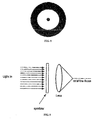
- An axicon has the property each axial location of the focus corresponds to a unique annulus at the input aperture of the axicon (see Fig. 3 ). This relationship could allow the reference arm length scanning to be replaced by scanning an annulus of illumination at the axicon aperture.
- a scan of another axis must be performed.
- This second scanning dimension is usually performed at a slower rate.
- Methods of accomplishing this slow scanning of the secondary axis include moving the sample arm optics, including the optical fiber, collimating lens and axicon, in the y direction (see Fig. 4B ), rotating the entire probe around the optical fiber axis (see Fig. 4C) or angularly deflecting the line focus in the x-y plane (see Fig. 4D). See, ( G.J. Tearney, S.A. Boppart, B.E. Bouma, M.E. Brezinski, N.J. Weissman, J.F. Southern, and J.G.
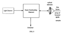
- Fig. 5 is a schematic of an alternative apparatus used to perform high transverse resolution ranging with a high depth of field.
- the system comprises a light source, beam redirecting element, detector, and an optical element.
- the optical element provides line focus and an array of focused spots on the sample.
- Fig. 6 shows an offset fiber array are directed by the mirror through the objective and used to displace focused (imaged) spots in the longitudinal and transverse dimensions on the sample.
- the spots are scanned (scan direction being indicated by the horizontal line and arrows) to create a multidimensional image.
- Fig. 7 is a schematic of a fiber array, microlens array and diffraction grating (array of mirrors) used to displace focused (imaged) spots in the longitudinal and transverse dimensions on the sample.
- Light from the light source (not shown) passes through the fibers in the array, and through the microlens array to the diffraction grating.
- Light directed by the grating passes through the objective lens and focused on the sample.
- the spots are scanned (scan direction being indicated by the horizontal line and arrows) to create a multidimensional image.
- An alternative means for providing a high transverse resolution over a large depth of focus is the use of a filter in the back plane of the imaging lens.
- This technique commonly termed apodization, allows the production of either a line focus as in the axicon or a multitude of focused spots positioned along the longitudinal dimension.
- the use of annular apodization to shape a beam focus has been previously described in the literature ( M. Martinez-Corral, P. Andres, J. Ojeda-Castaneda, G. Saavedra, Opt. Comm. 119, 491 (1995 )).
- use of apodization to create high transverse resolution over a large focal distance, where the longitudinal data is further resolved by OCT has not been previously described.
- Fig. 8 shows an embodiment of an apodized pupil plane filter.
- Fig. 9 shows a schematic of the use of an apodizer in front of an imaging lens the output of which is focused in the axial line.
- the present invention also provides a method of obtaining a high resolution and high depth of focus image of a sample, comprising:
- An advantage of the present invention is that the OCT imaging apparatus is capable of enabling sub-cellular resolution imaging along transverse and longitudinal dimensions of the sample in a compact, optical fiber-based package.
- Other advantages include the potential compact size and low cost of axial line focus optical elements such as the apodizer-lens combination or axicon.
Landscapes
- Physics & Mathematics (AREA)
- General Physics & Mathematics (AREA)
- Health & Medical Sciences (AREA)
- General Health & Medical Sciences (AREA)
- Nuclear Medicine, Radiotherapy & Molecular Imaging (AREA)
- Radiology & Medical Imaging (AREA)
- Optics & Photonics (AREA)
- Life Sciences & Earth Sciences (AREA)
- Chemical & Material Sciences (AREA)
- Analytical Chemistry (AREA)
- Biochemistry (AREA)
- Immunology (AREA)
- Pathology (AREA)
- Investigating Or Analysing Materials By Optical Means (AREA)
- Length Measuring Devices By Optical Means (AREA)
- Endoscopes (AREA)
- Microscoopes, Condenser (AREA)
- Instruments For Viewing The Inside Of Hollow Bodies (AREA)
- Measurement Of Optical Distance (AREA)
Abstract
Description
- This application claims the priority benefit of co-pending
U.S. Provisional Application No. 60/347,528 filed January 11, 2002 - The present invention relates to apparatus for imaging tissue samples using optical coherence tomography and incorporating an optical element to improve transverse resolution and depth of focus.
- Currently, the use of optical coherence tomography (OCT) is limited to the visualization of architectural morphological structures within biological tissues. The imaging of sub-cellular features with OCT has not been well demonstrated because of the relatively poor transverse resolution required to preserve depth of focus. The capability to perform high transverse resolution, large depth of field cross-sectional OCT imaging would permit application to early diagnosis of epithelial cancers and other biomedical imaging diagnostics that require sub-cellular level resolution.
- To date, there are no known optical coherence tomography configurations that can perform high transverse resolution imaging over a large depth of field. It would be desirable to have a simple device for performing high transverse resolution, large depth of field optical coherence tomography. In addition, by allowing light delivery through a single optical fiber, this device would be also be easily incorporated into catheters or endoscopes. These properties would make this device an enabling technology for performing optical coherence tomography in applications requiring sub-cellular resolution imaging at remote sites within biological systems.
- The invention is illustrated in the drawings in which like reference characters designate the same or similar parts throughout the figures of which:
-
Fig. 1 is a schematic view describing focusing using a refractive axicon. A collimated beam, incident from the left, is focused to an axial line with a narrow width and large depth. -
Fig. 2 is a schematic view of an OCT system with axicon optic in sample arm. -
Fig. 3 is a schematic view of the relationship between axial location and annulus of illumination. -
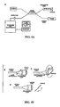
Fig. 4A is a schematic view of the image formation. -
Fig. 4B is a schematic view of the translation of the entire optical assembly in the y-direction. - Fig. 4C is a schematic view of the rotation of the entire optical assembly.
- Fig. 4D is a schematic view of the angular deflection of the axial line focus in the x-y plane.
-
Fig. 5 is a schematic view of a system used to perform high transverse resolution ranging with a high depth of field. -
Fig. 6 is a schematic view of an offset fiber array. -
Fig. 7 is a schematic of a fiber array, microlens array and diffraction grating. -
Fig. 8 is a schematic view of an embodiment of an apodized pupil plane filter. -
Fig. 9 is a schematic view of the use of an apodizer in front of an imaging lens. - "Axicon" shall mean any optic element (or combination thereof) capable of generating an axial line focus. Refractive, diffractive, and reflective axicons have been demonstrated. See, J.H. McLeod, J. Opt. Soc. Am 44, 592 (1954); J.H. McLeod, J. Opt. Soc. Am 50, 166 (1960); and J.R. Rayces, J. Opt. Soc. Am. 48, 576 (1958).
- "Depth of focus" shall mean the longitudinal distance over which the beam diameter increases by a factor ζ (typically ζ = sqrt(2) or 2). For a Gaussian beam, the sqrt(2) depth of focus is

- For a typical Gaussian spot size (1/e2 diameter) of d = 5 µm, and a wavelength of 830 nm, the depth of focus is approximately 48 µm. The depth of focus for a uniform beam (3 dB full-width-half-maximum intensity response for a planar reflector moved through the longitudinal plane) may be defined as

- For a NA = 0.2, which produces a spot size of 5 µm, the depth of focus for a uniform beam is approximately 17 µm at 830 nm.
- "Longitudinal" shall mean substantially parallel to the optical axis.
- "Longitudinal resolution" shall mean the minimum distance, Δz, in the longitudinal direction that two points may be separated while still being differentiated by an optical detection means.
- "Spot size" shall mean the transverse diameter of a focused spot. For a Gaussian beam, the spot size is defined as transverse width of the spot where the intensity at the focus has decreased by a factor of 1/e2. For a collimated Gaussian beam, the spot size, d, is defined as

where D is the beam diameter at the lens, f is the focal length of the lens and λ is the wavelength. For a flat top or uniform beam, the spot radius is defined as the transverse position of the first zero of the Airy disk,
where
and n is the refractive index of the immersion medium. - "Transverse" shall mean substantially perpendicular to the optical axis.
- "Transverse resolution" shall mean the minimum distance, Δr, in the transverse direction that two points may be separated while still being differentiated by an optical detection means. One commonly used approximation is Δr = d (for a Gaussian beam) or Δr = w (for a uniform beam).
- An axial line focus, with a narrow transverse beam diameter and over a large length (or depth of focus), is generated. Used in conjunction with OCT, the diameter of the line focus determines the transverse resolution and the length determines the depth of field. As in standard OCT, the detection of light backreflected from sites along the axial focus is performed using a Michelson interferometer. When the light source has a finite spectral width, this configuration can be used to determine the axial location of the backreflection site. The axial resolution is determined by the coherence length of the light source.
- Those of ordinary skill in the art will appreciate that there are a variety of known devices for generating a line focus. An axicon (reflective, transmissive, or diffractive optical element ("DOE")) is an acceptable model known to those skilled in the art for this and will be the method that is used in the present invention to demonstrate use of OCT with an axial line focus to achieve high resolution imaging over large depths of field. It is to be understood that this method is illustrative and not intended to be the exclusive model. Other known models include, but are not limited to, multi-focal lenses, such as the Rayleigh-Wood lens (Optical Processing and Computing, H.H Arsenault, T. Szoplik, and B. Macukow eds., Academic Press Inc., San Diego, CA, 1989), the use of chromatic aberration to produce an array of wavelength dependent foci along the longitudinal axis, and the like.
- The following section discusses the physical principles of a representative axicon that uses refraction, as shown in
Fig. 1 . The intensity distribution of light transmitted through a refractive axicon lens (see R. Arimoto, C. Saloma, T. Tanaka, and S. Kawata, Appl. Opt. 31, 6653 (1992)) is given by Equation (1):
where E2(R) is the intensity of the light incident on the axicon as a function of the radius R, λ is the wavelength of the light, and β is the half angle of the light transmitted through the axicon. The cone angle α is related to β and the depth of focus, zD, by Equations (2a) and (2b):

where n is the refractive index of the axicon. The above equations can be used to determine the diameter of the axial line focus. For plane wave illumination the focus diameter is given by Equation (3):
- In the case of reflective or diffractive axicons, Equation (1) is modified, but in all cases it is the diameter of the axial focus that determines the transverse resolution of the imaging system. A theme of the present invention is that the poor transverse resolution typical of current OCT systems can be improved by changing from a standard focusing geometry in which the focal volume (power distribution) is limited in both the transverse and the axial dimensions to one in which the focal volume is limited only in the transverse direction.
- By combining the high transverse localization (and weak axial localization) of an axicon with OCT (see
Fig. 2 ), an imaging system that provides high three-dimensional localization over large field sizes can be realized. Axial resolution for this imaging technique is determined solely by the coherence length of the light source (E.A. Swanson, D. Huang, M.R Hee, J.G. Fujimoto, C.P. Lin, and C.A. Puliafito, Opt. Lett. 17, 151 (1992)) and is given by Equation (4):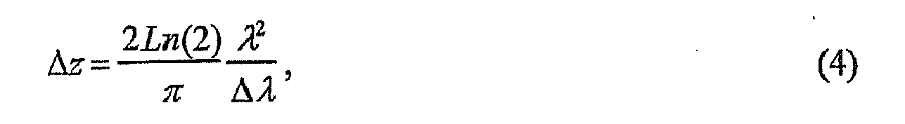
where Δλ is the spectral width (full-width half maximum ("FWHM")) of the light source. - In a preferred embodiment, the optical element has a transverse resolution defined as Δr=d0 being in the range of about 0.5 µm to about 10 µm, more preferably less than or equal to about 5µm. The optical element preferably has a Δz = zD of at least about 50 µm.
-
Fig. 4A illustrates the entire OCT/axicon system of one embodiment of the present invention. All components, other than the axicon probe, are standard to OCT. The use of OCT to determine the backreflection as a function of distance along the axial line focus provides a one dimensional raster scan. This is typically accomplished by scanning the length of the interferometer reference arm. An axicon has the property each axial location of the focus corresponds to a unique annulus at the input aperture of the axicon (seeFig. 3 ). This relationship could allow the reference arm length scanning to be replaced by scanning an annulus of illumination at the axicon aperture. - Regardless of how the axial dimension is scanned, to obtain an image a scan of another axis must be performed. This second scanning dimension is usually performed at a slower rate. Methods of accomplishing this slow scanning of the secondary axis include moving the sample arm optics, including the optical fiber, collimating lens and axicon, in the y direction (see
Fig. 4B ), rotating the entire probe around the optical fiber axis (see Fig. 4C) or angularly deflecting the line focus in the x-y plane (see Fig. 4D). See, (G.J. Tearney, S.A. Boppart, B.E. Bouma, M.E. Brezinski, N.J. Weissman, J.F. Southern, and J.G. Fujimoto, Opt. Lett. 21, 543 (1996)) and (S.A. Boppart, B.E. Bouma, C. Pitris, G.J. Tearney, J.G. Fujimoto, and M.E. Brezinski, Opt. Lett. 22, 1618 (1997)). Both linear motion along the y or z axis and rotation are easily accomplished in a compact probe by use of piezoelectric transducers or mechanical or pneumatic actuators. -
Fig. 5 is a schematic of an alternative apparatus used to perform high transverse resolution ranging with a high depth of field. The system comprises a light source, beam redirecting element, detector, and an optical element. The optical element provides line focus and an array of focused spots on the sample. -
Fig. 6 shows an offset fiber array are directed by the mirror through the objective and used to displace focused (imaged) spots in the longitudinal and transverse dimensions on the sample. The spots are scanned (scan direction being indicated by the horizontal line and arrows) to create a multidimensional image. -
Fig. 7 is a schematic of a fiber array, microlens array and diffraction grating (array of mirrors) used to displace focused (imaged) spots in the longitudinal and transverse dimensions on the sample. Light from the light source (not shown) passes through the fibers in the array, and through the microlens array to the diffraction grating. Light directed by the grating passes through the objective lens and focused on the sample. The spots are scanned (scan direction being indicated by the horizontal line and arrows) to create a multidimensional image. - An alternative means for providing a high transverse resolution over a large depth of focus is the use of a filter in the back plane of the imaging lens. This technique, commonly termed apodization, allows the production of either a line focus as in the axicon or a multitude of focused spots positioned along the longitudinal dimension. The use of annular apodization to shape a beam focus has been previously described in the literature (M. Martinez-Corral, P. Andres, J. Ojeda-Castaneda, G. Saavedra, Opt. Comm. 119, 491 (1995)). However, use of apodization to create high transverse resolution over a large focal distance, where the longitudinal data is further resolved by OCT has not been previously described.
-
Fig. 8 shows an embodiment of an apodized pupil plane filter. -
Fig. 9 shows a schematic of the use of an apodizer in front of an imaging lens the output of which is focused in the axial line. - The present invention also provides a method of obtaining a high resolution and high depth of focus image of a sample, comprising:
- a. providing a light source;
- b. directing light from said light source through an optical element to a sample by a light directing means, the optical element having a transverse resolution of less than about 5 µm and a depth of focus of greater than about 50 µm;
- c. receiving reflected light from the sample back through said optical element;
- d. directing said reflected light to a detector; and,
- e. processing the data from the detector to produce an image
- An advantage of the present invention is that the OCT imaging apparatus is capable of enabling sub-cellular resolution imaging along transverse and longitudinal dimensions of the sample in a compact, optical fiber-based package. Other advantages include the potential compact size and low cost of axial line focus optical elements such as the apodizer-lens combination or axicon.
- There has been described embodiments of the invention as summarised in various aspects in the following numbered clauses:
- 1. An apparatus for performing low coherence ranging of a sample with high transverse resolution and large depth of focus, comprising:
- a. an optical ranging system comprising
- i) a light source,
- ii) a means for directing light from said light source to said sample,
- iii) a means for directing reflected light from said sample to a detector,
- iv) at least one detector,
- v) a means for processing light data received by said detector and which generates an image; and
- b. an optical element having
- i) a transverse resolution defined as Δris less than or equal to about 5 µm, and
- ii) a depth of focus Δz of at least about 50 µm.
- a. an optical ranging system comprising
- 2. The apparatus of clause 1, wherein said light source is a broad spectral content light source.
- 3. The apparatus of clause 1, wherein said light source is a pulsed laser.
- 4. The apparatus of clause 1, wherein said light source is a continuous wave laser.
- 5. The apparatus of clause 1, wherein said means for directing light to and from said sample is an interferometer.
- 6. The apparatus of clause 1, wherein said means for directing light to and from said sample is optical wave guide lens.
- 7. The apparatus of clause 1, wherein said means for directing light to and from said sample is optical fiber lens.
- 8. The apparatus of clause 1, wherein said detector is a single detector.
- 9. The apparatus of clause 1, wherein said detector is an array of detectors.
- 10. The apparatus of clause 1, wherein said processor is capable of analyzing interferometric data.
- 11. The apparatus of clause 1, wherein said processor is capable of analyzing temporal detection.
- 12. The apparatus of clause 1, wherein said processor is capable of analyzing spectral analysis.
- 13. The apparatus of clause 1, wherein said optical element is an axicon lens element.
- 14. The apparatus of clause 13, wherein said optical element is transmissive.
- 15. The apparatus of clause 13, wherein said optical element is reflective.
- 16. The apparatus of clause 13, wherein said optical element is refractive.
- 17. The apparatus of clause 13, wherein said optical element is an apodized lens.
- 18. The apparatus of clause 13, wherein said optical element is a hologram.
- 19. The apparatus of clause 13, wherein said optical element is a combination of a diffractive element and a lens.
- 20. The apparatus of clause 13, wherein said optical element is a combination of an apodized lens, a hologram and a. diffractive element.
- 21. An apparatus for performing low coherence ranging of a sample with high transverse resolution and large depth of focus, comprising:
- a. an optical ranging system comprising
- i) a light source,
- ii) a means for directing light from said light source to said sample,
- iii) a means for directing reflected light from said sample to a detector,
- iv) a detector;
- b. a means for processing light data received by said detector and which generates an image; and
- c. an optical element that produces a plurality of focused spots that are distributed in depth.
- a. an optical ranging system comprising
- 22. The apparatus of clause 21, wherein said plurality of focused spots are in a straight vertical line.
- 23. The apparatus of clause 21, wherein said plurality of focused spots are at an angle with respect to said vertical plane.
- 24. The apparatus of clause 21, wherein said plurality of focused spots has a different longitudinal location.
- 25. The apparatus of clause 21, wherein said optical element is an axicon lens element.
- 26. The apparatus of clause 25, wherein said optical element is transmissive.
- 27. The apparatus of clause 25, wherein said optical element is reflective.
- 28. The apparatus of clause 25, wherein said optical element is refractive.
- 29. The apparatus of clause 25, wherein said optical element is an apodized lens.
- 30. The apparatus of clause 25, wherein said optical element is a hologram.
- 31. The apparatus of clause 25, wherein said optical element is a combination of a diffractive element and a lens.
- 32. The apparatus of clause 25, wherein said optical element is a combination of an apodized lens, a hologram and a diffractive element.
- 33. The apparatus of clause 21, further comprising means for producing multiple object spots, such mat each spot has a unique distance from its origin to said optical element such that the image of each spot has a unique longitudinal location.
- 34. The apparatus of clause 33, wherein said multiple spot generation means comprises multiple optical fibers.
- 35. The apparatus of clause 33, wherein said multiple spot generation means comprises aperture mask
- 36. The apparatus of clause 33, wherein said multiple spot generation means comprises diffraction grating
- 37. The apparatus of clause 33, wherein said multiple spot generation means comprises microlens array
- 38. The apparatus of clause 21, further comprising a means for scanning said means for directing light to and from said sample.
- 39. The apparatus of clause 21, further comprising a means for scanning said light.
- 40. The apparatus of clause 38, wherein said scanning means is a scanning mirror.
- 41. The apparatus of clause 38, wherein said scanning means is a means for moving the fiber with respect to said optical element.
- 42. The apparatus of clause 38, wherein said scanning means is a means for moving both said fiber and said optical element.
- 43. The apparatus of clause 38, wherein said scanning means is a means for moving the beam emanating from said optical fiber.
- 44. The apparatus of clause 38, wherein said scanning means is a means for changing the angle of the beam with respect to said optical elements.
- 45. The apparatus of clause 21, further comprising a sheath for enclosing said apparatus.
- 46. The apparatus of clause 21, further comprising a means for scanning said axial focus
- 47. A method of obtaining a high resolution and high depth of focus image of a sample, comprising:
- a. providing a light source;
- b. directing light from said light source through an optical element to a sample by a light directing means;
- c. receiving reflected light from the sample back through said optical element;
- d. directing said reflected light to a detector; and,
- e. processing the data from the detector to produce an image,
wherein said optical element has transverse resolution of less than 5 µm and a depth of focus of greater than 50 µm.
-
- 1. An apparatus for imaging at least a portion of a sample, comprising:
- a first interferometric arrangement providing an electro-magnetic radiation; and
- a second arrangement configured to receive the electro-magnetic radiation, and configured to generate a resultant electro-magnetic intensity distribution,
- wherein, along a particular direction, the intensity distribution is approximately constant for at least a predetermined distance.
- 2. An apparatus for imaging at least a portion of a sample, comprising:
- a first interferometric arrangement providing an electro-magnetic radiation; and
- a second arrangement configured to receive the electro-magnetic radiation, and configured to generate a resultant electro-magnetic intensity distribution,
- wherein, along a particular direction, widths of at least two sections of the intensity distribution are approximately the same.
- 3. The apparatus according to clause 2, wherein, along a particular direction, the intensity distribution is approximately constant for at least a predetermined distance.
- 4. The apparatus according to any one of clauses 1 to 3, wherein the second arrangement is an optical arrangement which is configured to optically image the sample.
- 5. The apparatus according to any one of clauses 1 to 3, wherein the second arrangement is an axicon lens.
- 6. The apparatus according to any one of clauses 1 to 3, wherein the second arrangement is a defractive optical element.
- 7. The apparatus according to any one of clauses 1 to 3, wherein the second arrangement is an annulus.
- 8. The apparatus according to any one of clauses 1 to 3, wherein the second arrangement includes a combination of a diffractive element and a lens.
- 9. The apparatus according to any one of clauses 1 to 3, wherein the second arrangement includes a combination of an apodized lens, a hologram and a diffractive element.
- 10. The apparatus according to any one of clauses 1 to 3, wherein the intensity distribution is a Bessel beam.
- 11. The apparatus according to any one of clauses 1 to 3, further comprising a third arrangement adapted to cooperate with the/second arrangement so as to translate at least one of the intensity distribution and the sample.
- 12. The apparatus according to clause 11, wherein the translation of the at least one of the intensity distribution and the sample produces an image which has 2 or more dimensions.
- 13. The apparatus according to any one of the preceding clauses, wherein the intensity distribution full width at half maximum is less than 10µm.
- 14. The apparatus according to any one of the preceding clauses, wherein the predetermined distance is at least 50µm.
- 15. The apparatus according to any one of the preceding clauses, wherein at least a portion of the intensity distribution includes a non-Gaussian distribution.
- 16. The apparatus according to any one of the preceding clauses, further comprising a fourth arrangement configured to receive information that is associated with the intensity distribution, and display an image on the received information.
- 17. The apparatus according to clause 2, wherein the particular direction is approximately a vertical direction.
- 18. The apparatus according to clause 2, wherein the second arrangement includes a plurality of lenses.
- 19. The apparatus according to clause 2, wherein one of the sections is at least partially above another one of the sections.
- 20. A method for imaging at least a portion of a sample, comprising:
- a) providing an electro-magnetic radiation using an interferometric arrangement;
- b) receiving the electro-magnetic radiation and generating a resultant electro-magnetic intensity distribution, wherein, along a particular direction, the intensity distribution is approximately constant for at least a predetermined distance.
- 21. A method for imaging at least a portion of a sample, comprising:
- a) providing an electro-magnetic radiation using an interferometric arrangement; and
- b) receiving the electro-magnetic radiation, and generating a resultant electro-magnetic intensity distribution, wherein, along a particular direction, widths of at least two sections of the intensity distribution are approximately the same.
- 22. The method according to clause 21, wherein, along a particular direction, the intensity distribution is approximately constant for at least a predetermined distance.
- 23. The method according to any one of clauses 20 to 22, wherein step (b) is performed using an optical arrangement which is configured to optically image the sample.
- 24. The method according to any one of clauses 20 to 22, wherein step (b) is performed using an axicon lens.
- 25. The method according to any one of clauses 20 to 22, wherein step (b) is performed using a defractive optical element.
- 26. The method according to any one of clauses 20 to 22, wherein step (b) is performed using an annulus.
- 27. The method according to any one of clauses 20 to 22, wherein step (b) is performed using a combination of a diffractive element and a lens.
- 28. The method according to any one of clauses 20 to 22, wherein step (b) is performed using a combination of an apodized lens, a hologram and a diffractive element.
- 29. The method according to any one of clauses 20 to 22, wherein the intensity distribution is a Bessel beam.
- 30. The method according to any one of clauses 20 to 22, further comprising the step of (c) translating at least one of the intensity distribution and the sample.
- 31. The method according to clause 30, wherein the translation of the at least one of the intensity distribution and the sample produces an image which has 2 or more dimensions.
- 32. The method according to anyone ofclauses 20 to 31, wherein the intensity distribution full width at half maximum is less than 10µm.
- 33. The method according to any one of clauses 20 to 32, wherein the predetermined distance is at least 50µm.
- 34. The method according to any one of clauses 20 to 33, wherein at least a portion of the intensity distribution includes a non-Gaussian distribution.
- 35. The method according to any one of clauses 20 to 34, further comprising the steps of receiving information that is associated with the intensity distribution; and displaying an image based on the received information.
- Although only a few exemplary embodiments of this invention have been described in detail above, those skilled in the art will readily appreciate that many modifications are possible in the exemplary embodiments without materially departing from the novel teachings and advantages of this invention. Accordingly, all such modifications are intended to be included within the scope of this invention as defined in the following claims. It should further be noted that any patents, applications and publications referred to herein are incorporated by reference in their entirety.
Claims (15)
- An OCT apparatus for imaging at least a portion of a sample, comprising:a first interferometric arrangement configured to provide an electro-magnetic radiation; anda second arrangement configured to receive the electro-magnetic radiation, and configured to generate a resultant electro-magnetic intensity distribution,wherein the second arrangement comprises an optical element havingi) a transverse resolution that is less than or equal to about 5 µm, andii) a depth of focus of at least about 50 µm.
- The apparatus according to claim 1, wherein, along a particular direction, the intensity distribution is approximately constant for at least a predetermined distance, and
wherein a wavelength of the electro-magnetic radiation remains approximately the same for at least the predetermined distance at which the intensity distribution is approximately constant. - The apparatus according to claim 1, wherein, along a particular direction, widths of at least two sections of the intensity distribution are approximately the same, and
wherein a wavelength of the electro-magnetic radiation remains approximately the same for at least the at least two sections of the intensity distribution. - The apparatus according to claim 3, wherein, along a particular direction, the intensity distribution is approximately constant for at least a predetermined distance.
- The apparatus according to any one of claims 1 to 3, wherein the second arrangement is one of an optical arrangement which is configured to optically image the sample, an axicon lens, a defractive optical element, an annulus, or includes a combination of a diffractive element and a lens, or includes a combination of an apodized lens, a hologram and a diffractive element, or includes a plurality of lenses.
- The apparatus according to any one of claims 1 to 4, wherein the intensity distribution is a Bessel beam.
- The apparatus according to any one of claims 1 to 4, further comprising a third arrangement configured to cooperate with the second arrangement so as to translate at least one of the intensity distribution and the sample.
- The apparatus according to claim 7, wherein the translation of the at least one of the intensity distribution and the sample produces an image which has 2 or more dimensions.
- The apparatus according to any one of the preceding claims, wherein at least a portion of the intensity distribution includes a non-Gaussian distribution.
- The apparatus according to any one of the preceding claims, further comprising a fourth arrangement configured to receive information that is associated with the intensity distribution, and display an image on the received information.
- The apparatus according to claim 3, wherein the particular direction is approximately a vertical direction.
- The apparatus according to claim 3, wherein one of the sections is at least partially above another one of the sections.
- The apparatus according to claim 2 or claim 3, wherein the second arrangement is further configured to focus the received electromagnetic radiation to generate the resultant electro-magnetic intensity distribution.
- The apparatus according to claim 2 or claim 3, wherein the resultant electro-magnetic intensity distribution is constant in the particular direction within the sample.
- A method for imaging at least a portion of a sample, comprising:a) providing an electro-magnetic radiation using an interferometric arrangement;b) receiving the electro-magnetic radiation and generating a resultant electro-magnetic intensity distribution at a second arrangement wherein the second arrangement comprises an optical element havingi) a transverse resolution that is less than or equal to about 5 µm, andii) a depth of focus of at least about 50 µm.
Applications Claiming Priority (2)
| Application Number | Priority Date | Filing Date | Title |
|---|---|---|---|
| US34752802P | 2002-01-11 | 2002-01-11 | |
| EP03705716A EP1468245B1 (en) | 2002-01-11 | 2003-01-10 | Apparatus for OCT imaging with axial line focus for improved resolution and depth of field |
Related Parent Applications (2)
| Application Number | Title | Priority Date | Filing Date |
|---|---|---|---|
| EP03705716.3 Division | 2003-01-10 | ||
| EP03705716A Division EP1468245B1 (en) | 2002-01-11 | 2003-01-10 | Apparatus for OCT imaging with axial line focus for improved resolution and depth of field |
Publications (2)
| Publication Number | Publication Date |
|---|---|
| EP2290318A1 true EP2290318A1 (en) | 2011-03-02 |
| EP2290318B1 EP2290318B1 (en) | 2015-08-26 |
Family
ID=32987184
Family Applications (4)
| Application Number | Title | Priority Date | Filing Date |
|---|---|---|---|
| EP10181750.0A Expired - Lifetime EP2290319B1 (en) | 2002-01-11 | 2003-01-10 | Apparatus for OCT imaging with axial line focus for improved resolution and depth of field |
| EP10181734.4A Expired - Lifetime EP2290318B1 (en) | 2002-01-11 | 2003-01-10 | Apparatus for OCT imaging with axial line focus for improved resolution and depth of field |
| EP03705716A Expired - Lifetime EP1468245B1 (en) | 2002-01-11 | 2003-01-10 | Apparatus for OCT imaging with axial line focus for improved resolution and depth of field |
| EP20100179690 Ceased EP2327954A1 (en) | 2002-01-11 | 2003-01-10 | Apparatus for OCT imaging with axial line focus for improved resolution and depth of field |
Family Applications Before (1)
| Application Number | Title | Priority Date | Filing Date |
|---|---|---|---|
| EP10181750.0A Expired - Lifetime EP2290319B1 (en) | 2002-01-11 | 2003-01-10 | Apparatus for OCT imaging with axial line focus for improved resolution and depth of field |
Family Applications After (2)
| Application Number | Title | Priority Date | Filing Date |
|---|---|---|---|
| EP03705716A Expired - Lifetime EP1468245B1 (en) | 2002-01-11 | 2003-01-10 | Apparatus for OCT imaging with axial line focus for improved resolution and depth of field |
| EP20100179690 Ceased EP2327954A1 (en) | 2002-01-11 | 2003-01-10 | Apparatus for OCT imaging with axial line focus for improved resolution and depth of field |
Country Status (9)
| Country | Link |
|---|---|
| US (1) | US7310150B2 (en) |
| EP (4) | EP2290319B1 (en) |
| JP (1) | JP2005530128A (en) |
| CN (2) | CN101598685B (en) |
| AT (1) | ATE503982T1 (en) |
| AU (2) | AU2003207507A1 (en) |
| CA (1) | CA2473465C (en) |
| DE (1) | DE60336534D1 (en) |
| WO (1) | WO2003060423A2 (en) |
Cited By (1)
| Publication number | Priority date | Publication date | Assignee | Title |
|---|---|---|---|---|
| DE102013012692A1 (en) * | 2013-07-31 | 2015-02-05 | Fraunhofer-Gesellschaft zur Förderung der angewandten Forschung e.V. | Method and device for detecting foreign bodies or other scattering centers in optically transparent containers |
Families Citing this family (232)
| Publication number | Priority date | Publication date | Assignee | Title |
|---|---|---|---|---|
| WO2002036015A1 (en) | 2000-10-30 | 2002-05-10 | The General Hospital Corporation | Optical methods and systems for tissue analysis |
| US9295391B1 (en) | 2000-11-10 | 2016-03-29 | The General Hospital Corporation | Spectrally encoded miniature endoscopic imaging probe |
| AT411269B (en) * | 2001-11-05 | 2003-11-25 | Salzburger Aluminium Ag | ALUMINUM-SILICON ALLOYS WITH IMPROVED MECHANICAL PROPERTIES |
| EP1596716B1 (en) * | 2003-01-24 | 2014-04-30 | The General Hospital Corporation | System and method for identifying tissue using low-coherence interferometry |
| CA2519937C (en) | 2003-03-31 | 2012-11-20 | Guillermo J. Tearney | Speckle reduction in optical coherence tomography by path length encoded angular compounding |
| EP2008579B1 (en) | 2003-06-06 | 2016-11-09 | The General Hospital Corporation | Process and apparatus for a wavelength tuned light source |
| EP3045136B1 (en) | 2003-09-12 | 2021-02-24 | Vessix Vascular, Inc. | Selectable eccentric remodeling and/or ablation of atherosclerotic material |
| EP3009815B1 (en) | 2003-10-27 | 2022-09-07 | The General Hospital Corporation | Method and apparatus for performing optical imaging using frequency-domain interferometry |
| WO2006014392A1 (en) | 2004-07-02 | 2006-02-09 | The General Hospital Corporation | Endoscopic imaging probe comprising dual clad fibre |
| JP5053845B2 (en) | 2004-08-06 | 2012-10-24 | ザ ジェネラル ホスピタル コーポレイション | Method, system and software apparatus for determining at least one position in a sample using optical coherence tomography |
| ATE538714T1 (en) * | 2004-08-24 | 2012-01-15 | Gen Hospital Corp | METHOD, SYSTEM AND SOFTWARE ARRANGEMENT FOR DETERMINING THE ELASTIC MODULE |
| WO2006024015A1 (en) | 2004-08-24 | 2006-03-02 | The General Hospital Corporation | Method and apparatus for imaging of vessel segments |
| US8920414B2 (en) | 2004-09-10 | 2014-12-30 | Vessix Vascular, Inc. | Tuned RF energy and electrical tissue characterization for selective treatment of target tissues |
| US8396548B2 (en) | 2008-11-14 | 2013-03-12 | Vessix Vascular, Inc. | Selective drug delivery in a lumen |
| US9713730B2 (en) | 2004-09-10 | 2017-07-25 | Boston Scientific Scimed, Inc. | Apparatus and method for treatment of in-stent restenosis |
| WO2006037132A1 (en) | 2004-09-29 | 2006-04-06 | The General Hospital Corporation | System and method for optical coherence imaging |
| EP1816949A1 (en) * | 2004-11-29 | 2007-08-15 | The General Hospital Corporation | Arrangements, devices, endoscopes, catheters and methods for performing optical imaging by simultaneously illuminating and detecting multiple points on a sample |
| WO2006086700A2 (en) * | 2005-02-10 | 2006-08-17 | Lightlab Imaging, Inc. | Optical coherence tomography apparatus and methods |
| JP2008538612A (en) * | 2005-04-22 | 2008-10-30 | ザ ジェネラル ホスピタル コーポレイション | Configuration, system, and method capable of providing spectral domain polarization sensitive optical coherence tomography |
| EP2085929A1 (en) | 2005-04-28 | 2009-08-05 | The General Hospital Corporation | Evaluating optical coherence tomography information for an anatomical structure |
| JP5702049B2 (en) * | 2005-06-01 | 2015-04-15 | ザ ジェネラル ホスピタル コーポレイション | Apparatus, method and system for performing phase resolved optical frequency domain imaging |
| EP2207008A1 (en) * | 2005-08-09 | 2010-07-14 | The General Hospital Corporation | Apparatus and method for performing polarization-based quadrature demodulation in optical coherence tomography |
| US8784336B2 (en) | 2005-08-24 | 2014-07-22 | C. R. Bard, Inc. | Stylet apparatuses and methods of manufacture |
| EP1928306B1 (en) | 2005-09-29 | 2021-01-13 | General Hospital Corporation | Optical coherence tomography systems and methods including fluorescence microscopic imaging of one or more biological structures |
| US20070238955A1 (en) * | 2006-01-18 | 2007-10-11 | The General Hospital Corporation | Systems and methods for generating data using one or more endoscopic microscopy techniques |
| US8145018B2 (en) | 2006-01-19 | 2012-03-27 | The General Hospital Corporation | Apparatus for obtaining information for a structure using spectrally-encoded endoscopy techniques and methods for producing one or more optical arrangements |
| EP2289398A3 (en) | 2006-01-19 | 2011-04-06 | The General Hospital Corporation | Methods and systems for optical imaging of epithelial luminal organs by beam scanning thereof |
| US20090128824A1 (en) * | 2006-01-24 | 2009-05-21 | Rainer Leitgeb | Optical imaging system with extended depth of focus |
| JP4483793B2 (en) * | 2006-01-27 | 2010-06-16 | セイコーエプソン株式会社 | Microstructure manufacturing method and manufacturing apparatus |
| EP2659851A3 (en) | 2006-02-01 | 2014-01-15 | The General Hospital Corporation | Apparatus for applying a plurality of electro-magnetic radiations to a sample |
| JP5524487B2 (en) | 2006-02-01 | 2014-06-18 | ザ ジェネラル ホスピタル コーポレイション | A method and system for emitting electromagnetic radiation to at least a portion of a sample using a conformal laser treatment procedure. |
| EP1987318B1 (en) | 2006-02-24 | 2015-08-12 | The General Hospital Corporation | Methods and systems for performing angle-resolved fourier-domain optical coherence tomography |
| US8019435B2 (en) | 2006-05-02 | 2011-09-13 | Boston Scientific Scimed, Inc. | Control of arterial smooth muscle tone |
| EP3150110B1 (en) | 2006-05-10 | 2020-09-02 | The General Hospital Corporation | Processes, arrangements and systems for providing frequency domain imaging of a sample |
| US20080024767A1 (en) * | 2006-07-28 | 2008-01-31 | Peter Seitz | Imaging optical coherence tomography with dynamic coherent focus |
| WO2008016927A2 (en) * | 2006-08-01 | 2008-02-07 | The General Hospital Corporation | Systems and methods for receiving and/or analyzing information associated with electro-magnetic radiation |
| CN100401974C (en) * | 2006-09-08 | 2008-07-16 | 浙江大学 | Method and system for realizing axial super resolution in tomography of optical coherent |
| ES2560006T3 (en) | 2006-10-18 | 2016-02-17 | Vessix Vascular, Inc. | Induction of desirable temperature effects on body tissue |
| AU2007310991B2 (en) | 2006-10-18 | 2013-06-20 | Boston Scientific Scimed, Inc. | System for inducing desirable temperature effects on body tissue |
| WO2008049118A2 (en) | 2006-10-19 | 2008-04-24 | The General Hospital Corporation | Apparatus and method for obtaining and providing imaging information associated with at least one portion of a sample and effecting such portion(s) |
| US8388546B2 (en) | 2006-10-23 | 2013-03-05 | Bard Access Systems, Inc. | Method of locating the tip of a central venous catheter |
| US7794407B2 (en) | 2006-10-23 | 2010-09-14 | Bard Access Systems, Inc. | Method of locating the tip of a central venous catheter |
| US20080118886A1 (en) * | 2006-11-21 | 2008-05-22 | Rongguang Liang | Apparatus for dental oct imaging |
| US8360963B2 (en) * | 2006-12-22 | 2013-01-29 | Koninklijke Philips Electronics N.V. | Imaging system with two imaging modalities |
| US7949019B2 (en) * | 2007-01-19 | 2011-05-24 | The General Hospital | Wavelength tuning source based on a rotatable reflector |
| US20080234567A1 (en) * | 2007-03-19 | 2008-09-25 | The General Hospital Corporation | Apparatus and method for providing a noninvasive diagnosis of internal bleeding |
| US10534129B2 (en) | 2007-03-30 | 2020-01-14 | The General Hospital Corporation | System and method providing intracoronary laser speckle imaging for the detection of vulnerable plaque |
| WO2009033111A2 (en) | 2007-09-06 | 2009-03-12 | Lensx Lasers, Inc. | Precise targeting of surgical photodisruption |
| WO2009036453A1 (en) * | 2007-09-15 | 2009-03-19 | The General Hospital Corporation | Apparatus, computer-accessible medium and method for measuring chemical and/or molecular compositions of coronary atherosclerotic plaques in anatomical structures |
| EP2040059A3 (en) * | 2007-09-19 | 2013-09-04 | FUJIFILM Corporation | Optical tomography imaging system, contact area detecting method and image processing method using the same, and optical tomographic image obtaining method |
| US9649048B2 (en) | 2007-11-26 | 2017-05-16 | C. R. Bard, Inc. | Systems and methods for breaching a sterile field for intravascular placement of a catheter |
| US8849382B2 (en) | 2007-11-26 | 2014-09-30 | C. R. Bard, Inc. | Apparatus and display methods relating to intravascular placement of a catheter |
| ES2651898T3 (en) | 2007-11-26 | 2018-01-30 | C.R. Bard Inc. | Integrated system for intravascular catheter placement |
| US10751509B2 (en) | 2007-11-26 | 2020-08-25 | C. R. Bard, Inc. | Iconic representations for guidance of an indwelling medical device |
| US8781555B2 (en) | 2007-11-26 | 2014-07-15 | C. R. Bard, Inc. | System for placement of a catheter including a signal-generating stylet |
| US10524691B2 (en) | 2007-11-26 | 2020-01-07 | C. R. Bard, Inc. | Needle assembly including an aligned magnetic element |
| US9521961B2 (en) | 2007-11-26 | 2016-12-20 | C. R. Bard, Inc. | Systems and methods for guiding a medical instrument |
| US9636031B2 (en) | 2007-11-26 | 2017-05-02 | C.R. Bard, Inc. | Stylets for use with apparatus for intravascular placement of a catheter |
| US10449330B2 (en) | 2007-11-26 | 2019-10-22 | C. R. Bard, Inc. | Magnetic element-equipped needle assemblies |
| US20090225324A1 (en) * | 2008-01-17 | 2009-09-10 | The General Hospital Corporation | Apparatus for providing endoscopic high-speed optical coherence tomography |
| US11123047B2 (en) | 2008-01-28 | 2021-09-21 | The General Hospital Corporation | Hybrid systems and methods for multi-modal acquisition of intravascular imaging data and counteracting the effects of signal absorption in blood |
| US8478382B2 (en) | 2008-02-11 | 2013-07-02 | C. R. Bard, Inc. | Systems and methods for positioning a catheter |
| WO2009137701A2 (en) | 2008-05-07 | 2009-11-12 | The General Hospital Corporation | System, method and computer-accessible medium for tracking vessel motion during three-dimensional coronary artery microscopy |
| EP2309923B1 (en) | 2008-07-14 | 2020-11-25 | The General Hospital Corporation | Apparatus and methods for color endoscopy |
| ES2525525T3 (en) | 2008-08-22 | 2014-12-26 | C.R. Bard, Inc. | Catheter assembly that includes ECG and magnetic sensor assemblies |
| US8437833B2 (en) | 2008-10-07 | 2013-05-07 | Bard Access Systems, Inc. | Percutaneous magnetic gastrostomy |
| ES2615826T3 (en) | 2008-11-11 | 2017-06-08 | Shifamed Holdings, Llc | Low Profile Electrode Set |
| US9795442B2 (en) | 2008-11-11 | 2017-10-24 | Shifamed Holdings, Llc | Ablation catheters |
| WO2010056745A1 (en) | 2008-11-17 | 2010-05-20 | Minnow Medical, Inc. | Selective accumulation of energy with or without knowledge of tissue topography |
| ES2745861T3 (en) | 2009-06-12 | 2020-03-03 | Bard Access Systems Inc | Apparatus, computer-aided data-processing algorithm, and computer storage medium for positioning an endovascular device in or near the heart |
| US9445734B2 (en) | 2009-06-12 | 2016-09-20 | Bard Access Systems, Inc. | Devices and methods for endovascular electrography |
| US9532724B2 (en) | 2009-06-12 | 2017-01-03 | Bard Access Systems, Inc. | Apparatus and method for catheter navigation using endovascular energy mapping |
| CA2764859C (en) | 2009-06-24 | 2018-09-25 | Shifamed, Llc | Steerable medical delivery devices and methods of use |
| CN102469943A (en) * | 2009-07-14 | 2012-05-23 | 通用医疗公司 | Apparatus, systems and methods for measuring flow and pressure within a vessel |
| WO2011091502A1 (en) * | 2009-10-01 | 2011-08-04 | Thunder Bay Regional Research Institute | Apparatus and methods for optical coherence tomography and confocal microscopy |
| US10639008B2 (en) | 2009-10-08 | 2020-05-05 | C. R. Bard, Inc. | Support and cover structures for an ultrasound probe head |
| WO2011044421A1 (en) | 2009-10-08 | 2011-04-14 | C. R. Bard, Inc. | Spacers for use with an ultrasound probe |
| US8767216B2 (en) * | 2009-10-13 | 2014-07-01 | California Institute Of Technology | Holographically illuminated imaging devices |
| US9492322B2 (en) | 2009-11-16 | 2016-11-15 | Alcon Lensx, Inc. | Imaging surgical target tissue by nonlinear scanning |
| US8860948B2 (en) * | 2010-01-22 | 2014-10-14 | Ben Gurion University of the Negev Research and Development Authority Ltd.; Bar Ilan University | High resolution extended depth of field optical coherence tomography |
| CN102821679B (en) | 2010-02-02 | 2016-04-27 | C·R·巴德股份有限公司 | For the apparatus and method that catheter navigation and end are located |
| US8265364B2 (en) | 2010-02-05 | 2012-09-11 | Alcon Lensx, Inc. | Gradient search integrated with local imaging in laser surgical systems |
| US8414564B2 (en) | 2010-02-18 | 2013-04-09 | Alcon Lensx, Inc. | Optical coherence tomographic system for ophthalmic surgery |
| WO2011106324A2 (en) * | 2010-02-23 | 2011-09-01 | California Institute Of Technology | Nondiffracting beam detection devices for three-dimensional imaging |
| PT2542154T (en) * | 2010-03-05 | 2020-11-25 | Massachusetts Gen Hospital | Systems, methods and computer-accessible medium which provide microscopic images of at least one anatomical structure at a particular resolution |
| CN102917748B (en) | 2010-03-24 | 2015-04-01 | 施菲姆德控股有限责任公司 | Intravascular tissue disruption |
| CA2795229A1 (en) | 2010-04-09 | 2011-10-13 | Vessix Vascular, Inc. | Power generating and control apparatus for the treatment of tissue |
| US9192790B2 (en) | 2010-04-14 | 2015-11-24 | Boston Scientific Scimed, Inc. | Focused ultrasonic renal denervation |
| US9069130B2 (en) | 2010-05-03 | 2015-06-30 | The General Hospital Corporation | Apparatus, method and system for generating optical radiation from biological gain media |
| US9655677B2 (en) | 2010-05-12 | 2017-05-23 | Shifamed Holdings, Llc | Ablation catheters including a balloon and electrodes |
| EP2568905A4 (en) | 2010-05-12 | 2017-07-26 | Shifamed Holdings, LLC | Low profile electrode assembly |
| WO2011150069A2 (en) | 2010-05-25 | 2011-12-01 | The General Hospital Corporation | Apparatus, systems, methods and computer-accessible medium for spectral analysis of optical coherence tomography images |
| WO2011149972A2 (en) | 2010-05-25 | 2011-12-01 | The General Hospital Corporation | Systems, devices, methods, apparatus and computer-accessible media for providing optical imaging of structures and compositions |
| ES2778041T3 (en) | 2010-05-28 | 2020-08-07 | Bard Inc C R | Apparatus for use with needle insertion guidance system |
| EP2912999B1 (en) | 2010-05-28 | 2022-06-29 | C. R. Bard, Inc. | Apparatus for use with needle insertion guidance system |
| US10285568B2 (en) | 2010-06-03 | 2019-05-14 | The General Hospital Corporation | Apparatus and method for devices for imaging structures in or at one or more luminal organs |
| US8473067B2 (en) | 2010-06-11 | 2013-06-25 | Boston Scientific Scimed, Inc. | Renal denervation and stimulation employing wireless vascular energy transfer arrangement |
| US8398236B2 (en) | 2010-06-14 | 2013-03-19 | Alcon Lensx, Inc. | Image-guided docking for ophthalmic surgical systems |
| US9358365B2 (en) | 2010-07-30 | 2016-06-07 | Boston Scientific Scimed, Inc. | Precision electrode movement control for renal nerve ablation |
| US9408661B2 (en) | 2010-07-30 | 2016-08-09 | Patrick A. Haverkost | RF electrodes on multiple flexible wires for renal nerve ablation |
| US9463062B2 (en) | 2010-07-30 | 2016-10-11 | Boston Scientific Scimed, Inc. | Cooled conductive balloon RF catheter for renal nerve ablation |
| US9084609B2 (en) | 2010-07-30 | 2015-07-21 | Boston Scientific Scime, Inc. | Spiral balloon catheter for renal nerve ablation |
| US9155589B2 (en) | 2010-07-30 | 2015-10-13 | Boston Scientific Scimed, Inc. | Sequential activation RF electrode set for renal nerve ablation |
| WO2012024577A2 (en) | 2010-08-20 | 2012-02-23 | C.R. Bard, Inc. | Reconfirmation of ecg-assisted catheter tip placement |
| US8536545B2 (en) | 2010-09-09 | 2013-09-17 | California Institute Of Technology | Delayed emission detection devices and methods |
| US9532708B2 (en) | 2010-09-17 | 2017-01-03 | Alcon Lensx, Inc. | Electronically controlled fixation light for ophthalmic imaging systems |
| US8974451B2 (en) | 2010-10-25 | 2015-03-10 | Boston Scientific Scimed, Inc. | Renal nerve ablation using conductive fluid jet and RF energy |
| US9220558B2 (en) | 2010-10-27 | 2015-12-29 | Boston Scientific Scimed, Inc. | RF renal denervation catheter with multiple independent electrodes |
| EP2632324A4 (en) | 2010-10-27 | 2015-04-22 | Gen Hospital Corp | Apparatus, systems and methods for measuring blood pressure within at least one vessel |
| US8801693B2 (en) | 2010-10-29 | 2014-08-12 | C. R. Bard, Inc. | Bioimpedance-assisted placement of a medical device |
| JP5535043B2 (en) * | 2010-11-08 | 2014-07-02 | 三菱電機株式会社 | Resin identification device |
| US9028485B2 (en) | 2010-11-15 | 2015-05-12 | Boston Scientific Scimed, Inc. | Self-expanding cooling electrode for renal nerve ablation |
| US9089350B2 (en) | 2010-11-16 | 2015-07-28 | Boston Scientific Scimed, Inc. | Renal denervation catheter with RF electrode and integral contrast dye injection arrangement |
| US9668811B2 (en) | 2010-11-16 | 2017-06-06 | Boston Scientific Scimed, Inc. | Minimally invasive access for renal nerve ablation |
| US9326751B2 (en) | 2010-11-17 | 2016-05-03 | Boston Scientific Scimed, Inc. | Catheter guidance of external energy for renal denervation |
| US9060761B2 (en) | 2010-11-18 | 2015-06-23 | Boston Scientific Scime, Inc. | Catheter-focused magnetic field induced renal nerve ablation |
| US9192435B2 (en) | 2010-11-22 | 2015-11-24 | Boston Scientific Scimed, Inc. | Renal denervation catheter with cooled RF electrode |
| US9023034B2 (en) | 2010-11-22 | 2015-05-05 | Boston Scientific Scimed, Inc. | Renal ablation electrode with force-activatable conduction apparatus |
| US20120157993A1 (en) | 2010-12-15 | 2012-06-21 | Jenson Mark L | Bipolar Off-Wall Electrode Device for Renal Nerve Ablation |
| WO2012100095A1 (en) | 2011-01-19 | 2012-07-26 | Boston Scientific Scimed, Inc. | Guide-compatible large-electrode catheter for renal nerve ablation with reduced arterial injury |
| US9999354B2 (en) * | 2011-01-21 | 2018-06-19 | National Research Council Of Canada | Biological tissue inspection method and system |
| US9086536B2 (en) | 2011-03-09 | 2015-07-21 | California Institute Of Technology | Talbot imaging devices and systems |
| WO2012127880A1 (en) * | 2011-03-24 | 2012-09-27 | 株式会社ニコン | Observation device and observation method |
| US8946619B2 (en) | 2011-04-20 | 2015-02-03 | California Institute Of Technology | Talbot-illuminated imaging devices, systems, and methods for focal plane tuning |
| US9179843B2 (en) | 2011-04-21 | 2015-11-10 | Hassan Ghaderi MOGHADDAM | Method and system for optically evaluating proximity to the inferior alveolar nerve in situ |
| US8459794B2 (en) | 2011-05-02 | 2013-06-11 | Alcon Lensx, Inc. | Image-processor-controlled misalignment-reduction for ophthalmic systems |
| CN103764216B (en) | 2011-05-03 | 2016-08-17 | 施菲姆德控股有限责任公司 | Delivery catheter can be turned to |
| US9622913B2 (en) | 2011-05-18 | 2017-04-18 | Alcon Lensx, Inc. | Imaging-controlled laser surgical system |
| AU2012278809B2 (en) | 2011-07-06 | 2016-09-29 | C.R. Bard, Inc. | Needle length determination and calibration for insertion guidance system |
| TWI447352B (en) * | 2011-07-08 | 2014-08-01 | 私立中原大學 | Optical tomography system |
| WO2013013049A1 (en) | 2011-07-19 | 2013-01-24 | The General Hospital Corporation | Systems, methods, apparatus and computer-accessible-medium for providing polarization-mode dispersion compensation in optical coherence tomography |
| CN103813745B (en) | 2011-07-20 | 2016-06-29 | 波士顿科学西美德公司 | In order to visualize, be directed at and to melt transcutaneous device and the method for nerve |
| WO2013016203A1 (en) | 2011-07-22 | 2013-01-31 | Boston Scientific Scimed, Inc. | Nerve modulation system with a nerve modulation element positionable in a helical guide |
| USD724745S1 (en) | 2011-08-09 | 2015-03-17 | C. R. Bard, Inc. | Cap for an ultrasound probe |
| USD699359S1 (en) | 2011-08-09 | 2014-02-11 | C. R. Bard, Inc. | Ultrasound probe head |
| US10241028B2 (en) | 2011-08-25 | 2019-03-26 | The General Hospital Corporation | Methods, systems, arrangements and computer-accessible medium for providing micro-optical coherence tomography procedures |
| US8398238B1 (en) | 2011-08-26 | 2013-03-19 | Alcon Lensx, Inc. | Imaging-based guidance system for ophthalmic docking using a location-orientation analysis |
| WO2013055826A1 (en) | 2011-10-10 | 2013-04-18 | Boston Scientific Scimed, Inc. | Medical devices including ablation electrodes |
| EP2765940B1 (en) | 2011-10-11 | 2015-08-26 | Boston Scientific Scimed, Inc. | Off-wall electrode device for nerve modulation |
| US9420955B2 (en) | 2011-10-11 | 2016-08-23 | Boston Scientific Scimed, Inc. | Intravascular temperature monitoring system and method |
| US9364284B2 (en) | 2011-10-12 | 2016-06-14 | Boston Scientific Scimed, Inc. | Method of making an off-wall spacer cage |
| WO2013066631A1 (en) | 2011-10-18 | 2013-05-10 | The General Hospital Corporation | Apparatus and methods for producing and/or providing recirculating optical delay(s) |
| US9162046B2 (en) | 2011-10-18 | 2015-10-20 | Boston Scientific Scimed, Inc. | Deflectable medical devices |
| WO2013059202A1 (en) | 2011-10-18 | 2013-04-25 | Boston Scientific Scimed, Inc. | Integrated crossing balloon catheter |
| US9211107B2 (en) | 2011-11-07 | 2015-12-15 | C. R. Bard, Inc. | Ruggedized ultrasound hydrogel insert |
| CN104023662B (en) | 2011-11-08 | 2018-02-09 | 波士顿科学西美德公司 | Hole portion renal nerve melts |
| WO2013074813A1 (en) | 2011-11-15 | 2013-05-23 | Boston Scientific Scimed, Inc. | Device and methods for renal nerve modulation monitoring |
| US9119632B2 (en) | 2011-11-21 | 2015-09-01 | Boston Scientific Scimed, Inc. | Deflectable renal nerve ablation catheter |
| US9066784B2 (en) | 2011-12-19 | 2015-06-30 | Alcon Lensx, Inc. | Intra-surgical optical coherence tomographic imaging of cataract procedures |
| US9023016B2 (en) | 2011-12-19 | 2015-05-05 | Alcon Lensx, Inc. | Image processor for intra-surgical optical coherence tomographic imaging of laser cataract procedures |
| US9265969B2 (en) | 2011-12-21 | 2016-02-23 | Cardiac Pacemakers, Inc. | Methods for modulating cell function |
| US20130163003A1 (en) * | 2011-12-21 | 2013-06-27 | Ole Massow | Apparatus and method for optical swept-source coherence tomography |
| US9174050B2 (en) | 2011-12-23 | 2015-11-03 | Vessix Vascular, Inc. | Methods and apparatuses for remodeling tissue of or adjacent to a body passage |
| EP2797534A1 (en) | 2011-12-28 | 2014-11-05 | Boston Scientific Scimed, Inc. | Device and methods for nerve modulation using a novel ablation catheter with polymeric ablative elements |
| US9050106B2 (en) | 2011-12-29 | 2015-06-09 | Boston Scientific Scimed, Inc. | Off-wall electrode device and methods for nerve modulation |
| JP5655805B2 (en) * | 2012-03-21 | 2015-01-21 | 住友電気工業株式会社 | Optical probe and optical measurement method |
| EP2833776A4 (en) | 2012-03-30 | 2015-12-09 | Gen Hospital Corp | Imaging system, method and distal attachment for multidirectional field of view endoscopy |
| US8961550B2 (en) | 2012-04-17 | 2015-02-24 | Indian Wells Medical, Inc. | Steerable endoluminal punch |
| WO2013169927A1 (en) | 2012-05-08 | 2013-11-14 | Boston Scientific Scimed, Inc. | Renal nerve modulation devices |
| WO2013177154A1 (en) | 2012-05-21 | 2013-11-28 | The General Hospital Corporation | Apparatus, device and method for capsule microscopy |
| EP2861153A4 (en) | 2012-06-15 | 2016-10-19 | Bard Inc C R | Apparatus and methods for detection of a removable cap on an ultrasound probe |
| JP5828811B2 (en) * | 2012-07-23 | 2015-12-09 | キヤノン株式会社 | Imaging apparatus and control method thereof |
| EP2690395A1 (en) * | 2012-07-24 | 2014-01-29 | Hexagon Technology Center GmbH | Interferometric distance measuring assembly and method |
| EP2888616A4 (en) | 2012-08-22 | 2016-04-27 | Gen Hospital Corp | System, method, and computer-accessible medium for fabrication minature endoscope using soft lithography |
| CN104540465A (en) | 2012-08-24 | 2015-04-22 | 波士顿科学西美德公司 | Intravascular catheter with a balloon comprising separate microporous regions |
| WO2014043687A2 (en) | 2012-09-17 | 2014-03-20 | Boston Scientific Scimed, Inc. | Self-positioning electrode system and method for renal nerve modulation |
| WO2014047454A2 (en) | 2012-09-21 | 2014-03-27 | Boston Scientific Scimed, Inc. | Self-cooling ultrasound ablation catheter |
| US10398464B2 (en) | 2012-09-21 | 2019-09-03 | Boston Scientific Scimed, Inc. | System for nerve modulation and innocuous thermal gradient nerve block |
| US10835305B2 (en) | 2012-10-10 | 2020-11-17 | Boston Scientific Scimed, Inc. | Renal nerve modulation devices and methods |
| EP2929327B1 (en) | 2012-12-05 | 2019-08-14 | Perimeter Medical Imaging, Inc. | System and method for wide field oct imaging |
| KR20140089129A (en) | 2013-01-04 | 2014-07-14 | 삼성전자주식회사 | Optical zoom probe |
| JP6053138B2 (en) * | 2013-01-24 | 2016-12-27 | 株式会社日立エルジーデータストレージ | Optical tomographic observation apparatus and optical tomographic observation method |
| EP2948758B1 (en) | 2013-01-28 | 2024-03-13 | The General Hospital Corporation | Apparatus for providing diffuse spectroscopy co-registered with optical frequency domain imaging |
| WO2014120791A1 (en) | 2013-01-29 | 2014-08-07 | The General Hospital Corporation | Apparatus, systems and methods for providing information regarding the aortic valve |
| WO2014121082A1 (en) | 2013-02-01 | 2014-08-07 | The General Hospital Corporation | Objective lens arrangement for confocal endomicroscopy |
| US9956033B2 (en) | 2013-03-11 | 2018-05-01 | Boston Scientific Scimed, Inc. | Medical devices for modulating nerves |
| US9693821B2 (en) | 2013-03-11 | 2017-07-04 | Boston Scientific Scimed, Inc. | Medical devices for modulating nerves |
| US9808311B2 (en) | 2013-03-13 | 2017-11-07 | Boston Scientific Scimed, Inc. | Deflectable medical devices |
| US10478072B2 (en) | 2013-03-15 | 2019-11-19 | The General Hospital Corporation | Methods and system for characterizing an object |
| AU2014233354B2 (en) | 2013-03-15 | 2017-01-12 | Medtronic Af Luxembourg S.A.R.L. | Controlled neuromodulation systems and methods of use |
| JP6220044B2 (en) | 2013-03-15 | 2017-10-25 | ボストン サイエンティフィック サイムド,インコーポレイテッドBoston Scientific Scimed,Inc. | Medical device for renal nerve ablation |
| JP6139772B2 (en) | 2013-03-15 | 2017-05-31 | ボストン サイエンティフィック サイムド,インコーポレイテッドBoston Scientific Scimed,Inc. | Control unit for use with electrode pads and method for estimating leakage |
| US10265122B2 (en) | 2013-03-15 | 2019-04-23 | Boston Scientific Scimed, Inc. | Nerve ablation devices and related methods of use |
| US10098694B2 (en) | 2013-04-08 | 2018-10-16 | Apama Medical, Inc. | Tissue ablation and monitoring thereof |
| KR20150140760A (en) | 2013-04-08 | 2015-12-16 | 아파마 메디칼, 인크. | Cardiac ablation catheters and methods of use thereof |
| US10349824B2 (en) | 2013-04-08 | 2019-07-16 | Apama Medical, Inc. | Tissue mapping and visualization systems |
| WO2014186353A1 (en) | 2013-05-13 | 2014-11-20 | The General Hospital Corporation | Detecting self-interefering fluorescence phase and amplitude |
| CN105473091B (en) | 2013-06-21 | 2020-01-21 | 波士顿科学国际有限公司 | Renal denervation balloon catheter with co-movable electrode supports |
| WO2014205399A1 (en) | 2013-06-21 | 2014-12-24 | Boston Scientific Scimed, Inc. | Medical devices for renal nerve ablation having rotatable shafts |
| US9707036B2 (en) | 2013-06-25 | 2017-07-18 | Boston Scientific Scimed, Inc. | Devices and methods for nerve modulation using localized indifferent electrodes |
| JP6204579B2 (en) | 2013-07-01 | 2017-09-27 | ボストン サイエンティフィック サイムド,インコーポレイテッドBoston Scientific Scimed,Inc. | Renal nerve ablation medical device |
| CN105377169B (en) | 2013-07-11 | 2019-04-19 | 波士顿科学国际有限公司 | Device and method for neuromodulation |
| EP3019106A1 (en) | 2013-07-11 | 2016-05-18 | Boston Scientific Scimed, Inc. | Medical device with stretchable electrode assemblies |
| WO2015010074A1 (en) | 2013-07-19 | 2015-01-22 | Boston Scientific Scimed, Inc. | Spiral bipolar electrode renal denervation balloon |
| US10117576B2 (en) | 2013-07-19 | 2018-11-06 | The General Hospital Corporation | System, method and computer accessible medium for determining eye motion by imaging retina and providing feedback for acquisition of signals from the retina |
| EP4349242A2 (en) | 2013-07-19 | 2024-04-10 | The General Hospital Corporation | Imaging apparatus and method which utilizes multidirectional field of view endoscopy |
| CN105392435B (en) | 2013-07-22 | 2018-11-09 | 波士顿科学国际有限公司 | Renal nerve ablation catheter with twisting sacculus |
| US10342609B2 (en) | 2013-07-22 | 2019-07-09 | Boston Scientific Scimed, Inc. | Medical devices for renal nerve ablation |
| WO2015013651A2 (en) | 2013-07-26 | 2015-01-29 | The General Hospital Corporation | System, apparatus and method utilizing optical dispersion for fourier-domain optical coherence tomography |
| CN105473093B (en) | 2013-08-22 | 2019-02-05 | 波士顿科学国际有限公司 | Flexible circuit with the improved adhesion strength to renal nerve modulation sacculus |
| CN105555218B (en) | 2013-09-04 | 2019-01-15 | 波士顿科学国际有限公司 | With radio frequency (RF) foley's tube rinsed with cooling capacity |
| EP3043733A1 (en) | 2013-09-13 | 2016-07-20 | Boston Scientific Scimed, Inc. | Ablation balloon with vapor deposited cover layer |
| WO2015057521A1 (en) | 2013-10-14 | 2015-04-23 | Boston Scientific Scimed, Inc. | High resolution cardiac mapping electrode array catheter |
| US11246654B2 (en) | 2013-10-14 | 2022-02-15 | Boston Scientific Scimed, Inc. | Flexible renal nerve ablation devices and related methods of use and manufacture |
| US9770606B2 (en) | 2013-10-15 | 2017-09-26 | Boston Scientific Scimed, Inc. | Ultrasound ablation catheter with cooling infusion and centering basket |
| JP6259098B2 (en) | 2013-10-15 | 2018-01-10 | ボストン サイエンティフィック サイムド,インコーポレイテッドBoston Scientific Scimed,Inc. | Medical device and method for manufacturing the medical device |
| EP3057521B1 (en) | 2013-10-18 | 2020-03-25 | Boston Scientific Scimed, Inc. | Balloon catheters with flexible conducting wires |
| WO2015061457A1 (en) | 2013-10-25 | 2015-04-30 | Boston Scientific Scimed, Inc. | Embedded thermocouple in denervation flex circuit |
| CN105899157B (en) | 2014-01-06 | 2019-08-09 | 波士顿科学国际有限公司 | Tear-proof flexible circuit assembly |
| WO2015105870A1 (en) | 2014-01-08 | 2015-07-16 | The General Hospital Corporation | Method and apparatus for microscopic imaging |
| WO2015116986A2 (en) | 2014-01-31 | 2015-08-06 | The General Hospital Corporation | System and method for facilitating manual and/or automatic volumetric imaging with real-time tension or force feedback using a tethered imaging device |
| WO2015119890A1 (en) | 2014-02-04 | 2015-08-13 | Boston Scientific Scimed, Inc. | Alternative placement of thermal sensors on bipolar electrode |
| US11000679B2 (en) | 2014-02-04 | 2021-05-11 | Boston Scientific Scimed, Inc. | Balloon protection and rewrapping devices and related methods of use |
| CN105979868B (en) | 2014-02-06 | 2020-03-10 | C·R·巴德股份有限公司 | Systems and methods for guidance and placement of intravascular devices |
| WO2015153982A1 (en) | 2014-04-04 | 2015-10-08 | The General Hospital Corporation | Apparatus and method for controlling propagation and/or transmission of electromagnetic radiation in flexible waveguide(s) |
| JP2017522066A (en) * | 2014-06-10 | 2017-08-10 | カール ツァイス メディテック インコーポレイテッドCarl Zeiss Meditec Inc. | Imaging system and method with improved frequency domain interferometry |
| ES2907287T3 (en) | 2014-07-25 | 2022-04-22 | Massachusetts Gen Hospital | Apparatus for imaging and in vivo diagnosis |
| US10973584B2 (en) | 2015-01-19 | 2021-04-13 | Bard Access Systems, Inc. | Device and method for vascular access |
| CA2979884A1 (en) | 2015-03-27 | 2016-10-06 | Shifamed Holdings, Llc | Steerable medical devices, systems, and methods of use |
| EP3285849A4 (en) | 2015-04-24 | 2018-12-26 | Shifamed Holdings, LLC | Steerable medical devices, systems, and methods of use |
| US10349890B2 (en) | 2015-06-26 | 2019-07-16 | C. R. Bard, Inc. | Connector interface for ECG-based catheter positioning system |
| EP3373794B1 (en) | 2015-11-09 | 2022-01-05 | Kalila Medical, Inc. | Steering assemblies for medical devices |
| WO2017087549A1 (en) | 2015-11-16 | 2017-05-26 | Apama Medical, Inc. | Energy delivery devices |
| CN108431626B (en) * | 2015-12-20 | 2022-06-17 | 苹果公司 | Light detection and ranging sensor |
| JP6703839B2 (en) * | 2016-01-14 | 2020-06-03 | 株式会社トプコン | Ophthalmic measuring device |
| US11000207B2 (en) | 2016-01-29 | 2021-05-11 | C. R. Bard, Inc. | Multiple coil system for tracking a medical device |
| US10982947B2 (en) * | 2017-06-12 | 2021-04-20 | Sightline Innovation Inc. | System and method of surface inspection of an object using mulitplexed optical coherence tomography |
| WO2019014767A1 (en) | 2017-07-18 | 2019-01-24 | Perimeter Medical Imaging, Inc. | Sample container for stabilizing and aligning excised biological tissue samples for ex vivo analysis |
| CN108036726B (en) * | 2017-12-05 | 2020-12-22 | 中国科学院合肥物质科学研究院 | Device for measuring nanowire displacement by using polarization maintaining optical fiber and double micro lenses |
| JP6880513B2 (en) * | 2018-03-13 | 2021-06-02 | オムロン株式会社 | Optical measuring device and optical measuring method |
| WO2020081373A1 (en) | 2018-10-16 | 2020-04-23 | Bard Access Systems, Inc. | Safety-equipped connection systems and methods thereof for establishing electrical connections |
| EP3999897A1 (en) | 2019-07-17 | 2022-05-25 | Scoptonic SP. Z.O.O. | High sensitivity optical devices using pupil splittig means |
Family Cites Families (133)
| Publication number | Priority date | Publication date | Assignee | Title |
|---|---|---|---|---|
| US347528A (en) | 1886-08-17 | speee | ||
| US2339754A (en) * | 1941-03-04 | 1944-01-25 | Westinghouse Electric & Mfg Co | Supervisory apparatus |
| US4295738A (en) * | 1979-08-30 | 1981-10-20 | United Technologies Corporation | Fiber optic strain sensor |
| US4300816A (en) | 1979-08-30 | 1981-11-17 | United Technologies Corporation | Wide band multicore optical fiber |
| US5065331A (en) | 1981-05-18 | 1991-11-12 | Vachon Reginald I | Apparatus and method for determining the stress and strain in pipes, pressure vessels, structural members and other deformable bodies |
| US4601036A (en) * | 1982-09-30 | 1986-07-15 | Honeywell Inc. | Rapidly tunable laser |
| CH663466A5 (en) * | 1983-09-12 | 1987-12-15 | Battelle Memorial Institute | METHOD AND DEVICE FOR DETERMINING THE POSITION OF AN OBJECT IN RELATION TO A REFERENCE. |
| US4631498A (en) | 1985-04-26 | 1986-12-23 | Hewlett-Packard Company | CW Laser wavemeter/frequency locking technique |
| US5040889A (en) | 1986-05-30 | 1991-08-20 | Pacific Scientific Company | Spectrometer with combined visible and ultraviolet sample illumination |
| US4770492A (en) * | 1986-10-28 | 1988-09-13 | Spectran Corporation | Pressure or strain sensitive optical fiber |
| JPH0760273B2 (en) * | 1987-10-26 | 1995-06-28 | キヤノン株式会社 | Magnetic developer |
| FR2626367B1 (en) * | 1988-01-25 | 1990-05-11 | Thomson Csf | MULTI-POINT FIBER OPTIC TEMPERATURE SENSOR |
| FR2626383B1 (en) * | 1988-01-27 | 1991-10-25 | Commissariat Energie Atomique | EXTENDED FIELD SCAN AND DEPTH CONFOCAL OPTICAL MICROSCOPY AND DEVICES FOR CARRYING OUT THE METHOD |
| US4925302A (en) * | 1988-04-13 | 1990-05-15 | Hewlett-Packard Company | Frequency locking device |
| WO1990000754A1 (en) * | 1988-07-13 | 1990-01-25 | Martin Russell Harris | Scanning confocal microscope |
| GB8817672D0 (en) | 1988-07-25 | 1988-09-01 | Sira Ltd | Optical apparatus |
| US4868834A (en) * | 1988-09-14 | 1989-09-19 | The United States Of America As Represented By The Secretary Of The Army | System for rapidly tuning a low pressure pulsed laser |
| DE3833602A1 (en) * | 1988-10-03 | 1990-02-15 | Krupp Gmbh | SPECTROMETER FOR SIMULTANEOUS INTENSITY MEASUREMENT IN DIFFERENT SPECTRAL AREAS |
| EP0449883B1 (en) * | 1988-12-21 | 1996-01-31 | Massachusetts Institute Of Technology | A method for laser induced fluorescence of tissue |
| US5046501A (en) * | 1989-01-18 | 1991-09-10 | Wayne State University | Atherosclerotic identification |
| US5317389A (en) * | 1989-06-12 | 1994-05-31 | California Institute Of Technology | Method and apparatus for white-light dispersed-fringe interferometric measurement of corneal topography |
| US5039193A (en) * | 1990-04-03 | 1991-08-13 | Focal Technologies Incorporated | Fibre optic single mode rotary joint |
| US5262644A (en) | 1990-06-29 | 1993-11-16 | Southwest Research Institute | Remote spectroscopy for raman and brillouin scattering |
| US5197470A (en) * | 1990-07-16 | 1993-03-30 | Eastman Kodak Company | Near infrared diagnostic method and instrument |
| GB9015793D0 (en) | 1990-07-18 | 1990-09-05 | Medical Res Council | Confocal scanning optical microscope |
| US5127730A (en) | 1990-08-10 | 1992-07-07 | Regents Of The University Of Minnesota | Multi-color laser scanning confocal imaging system |
| US5305759A (en) * | 1990-09-26 | 1994-04-26 | Olympus Optical Co., Ltd. | Examined body interior information observing apparatus by using photo-pulses controlling gains for depths |
| US5202745A (en) * | 1990-11-07 | 1993-04-13 | Hewlett-Packard Company | Polarization independent optical coherence-domain reflectometry |
| JP3035336B2 (en) | 1990-11-27 | 2000-04-24 | 興和株式会社 | Blood flow measurement device |
| US5293872A (en) * | 1991-04-03 | 1994-03-15 | Alfano Robert R | Method for distinguishing between calcified atherosclerotic tissue and fibrous atherosclerotic tissue or normal cardiovascular tissue using Raman spectroscopy |
| US6111645A (en) * | 1991-04-29 | 2000-08-29 | Massachusetts Institute Of Technology | Grating based phase control optical delay line |
| WO1992019930A1 (en) * | 1991-04-29 | 1992-11-12 | Massachusetts Institute Of Technology | Method and apparatus for optical imaging and measurement |
| US5465147A (en) | 1991-04-29 | 1995-11-07 | Massachusetts Institute Of Technology | Method and apparatus for acquiring images using a ccd detector array and no transverse scanner |
| US6564087B1 (en) * | 1991-04-29 | 2003-05-13 | Massachusetts Institute Of Technology | Fiber optic needle probes for optical coherence tomography imaging |
| US5748598A (en) * | 1995-12-22 | 1998-05-05 | Massachusetts Institute Of Technology | Apparatus and methods for reading multilayer storage media using short coherence length sources |
| US6134003A (en) * | 1991-04-29 | 2000-10-17 | Massachusetts Institute Of Technology | Method and apparatus for performing optical measurements using a fiber optic imaging guidewire, catheter or endoscope |
| US5956355A (en) * | 1991-04-29 | 1999-09-21 | Massachusetts Institute Of Technology | Method and apparatus for performing optical measurements using a rapidly frequency-tuned laser |
| US5441053A (en) * | 1991-05-03 | 1995-08-15 | University Of Kentucky Research Foundation | Apparatus and method for multiple wavelength of tissue |
| DE4128744C1 (en) | 1991-08-29 | 1993-04-22 | Siemens Ag, 8000 Muenchen, De | |
| US5353790A (en) * | 1992-01-17 | 1994-10-11 | Board Of Regents, The University Of Texas System | Method and apparatus for optical measurement of bilirubin in tissue |
| US5248876A (en) | 1992-04-21 | 1993-09-28 | International Business Machines Corporation | Tandem linear scanning confocal imaging system with focal volumes at different heights |
| US5486701A (en) * | 1992-06-16 | 1996-01-23 | Prometrix Corporation | Method and apparatus for measuring reflectance in two wavelength bands to enable determination of thin film thickness |
| US5698397A (en) | 1995-06-07 | 1997-12-16 | Sri International | Up-converting reporters for biological and other assays using laser excitation techniques |
| US5772597A (en) * | 1992-09-14 | 1998-06-30 | Sextant Medical Corporation | Surgical tool end effector |
| US5383467A (en) * | 1992-11-18 | 1995-01-24 | Spectrascience, Inc. | Guidewire catheter and apparatus for diagnostic imaging |
| ES2102187T3 (en) * | 1992-11-18 | 1997-07-16 | Spectrascience Inc | DIAGNOSTIC DEVICE FOR IMAGE FORMATION. |
| US5987346A (en) | 1993-02-26 | 1999-11-16 | Benaron; David A. | Device and method for classification of tissue |
| DE4310209C2 (en) * | 1993-03-29 | 1996-05-30 | Bruker Medizintech | Optical stationary imaging in strongly scattering media |
| DE4314189C1 (en) | 1993-04-30 | 1994-11-03 | Bodenseewerk Geraetetech | Device for the examination of optical fibres made of glass by means of heterodyne Brillouin spectroscopy |
| EP0627643B1 (en) * | 1993-06-03 | 1999-05-06 | Hamamatsu Photonics K.K. | Laser scanning optical system using axicon |
| US5803082A (en) * | 1993-11-09 | 1998-09-08 | Staplevision Inc. | Omnispectramammography |
| US5983125A (en) | 1993-12-13 | 1999-11-09 | The Research Foundation Of City College Of New York | Method and apparatus for in vivo examination of subcutaneous tissues inside an organ of a body using optical spectroscopy |
| JP3261244B2 (en) * | 1993-12-17 | 2002-02-25 | ブラザー工業株式会社 | Scanning optical device |
| US5450203A (en) | 1993-12-22 | 1995-09-12 | Electroglas, Inc. | Method and apparatus for determining an objects position, topography and for imaging |
| US5590660A (en) * | 1994-03-28 | 1997-01-07 | Xillix Technologies Corp. | Apparatus and method for imaging diseased tissue using integrated autofluorescence |
| DE4411017C2 (en) * | 1994-03-30 | 1995-06-08 | Alexander Dr Knuettel | Optical stationary spectroscopic imaging in strongly scattering objects through special light focusing and signal detection of light of different wavelengths |
| TW275570B (en) * | 1994-05-05 | 1996-05-11 | Boehringer Mannheim Gmbh | |
| US5459325A (en) | 1994-07-19 | 1995-10-17 | Molecular Dynamics, Inc. | High-speed fluorescence scanner |
| US6159445A (en) | 1994-07-20 | 2000-12-12 | Nycomed Imaging As | Light imaging contrast agents |
| DE69528024T2 (en) | 1994-08-18 | 2003-10-09 | Zeiss Carl | Surgical apparatus controlled with optical coherence tomography |
| US5491524A (en) | 1994-10-05 | 1996-02-13 | Carl Zeiss, Inc. | Optical coherence tomography corneal mapping apparatus |
| US5817144A (en) * | 1994-10-25 | 1998-10-06 | Latis, Inc. | Method for contemporaneous application OF laser energy and localized pharmacologic therapy |
| US6033721A (en) * | 1994-10-26 | 2000-03-07 | Revise, Inc. | Image-based three-axis positioner for laser direct write microchemical reaction |
| US5600486A (en) | 1995-01-30 | 1997-02-04 | Lockheed Missiles And Space Company, Inc. | Color separation microlens |
| US5526338A (en) | 1995-03-10 | 1996-06-11 | Yeda Research & Development Co. Ltd. | Method and apparatus for storage and retrieval with multilayer optical disks |
| US5697373A (en) | 1995-03-14 | 1997-12-16 | Board Of Regents, The University Of Texas System | Optical method and apparatus for the diagnosis of cervical precancers using raman and fluorescence spectroscopies |
| US5735276A (en) | 1995-03-21 | 1998-04-07 | Lemelson; Jerome | Method and apparatus for scanning and evaluating matter |
| US5785651A (en) | 1995-06-07 | 1998-07-28 | Keravision, Inc. | Distance measuring confocal microscope |
| WO1997001167A1 (en) | 1995-06-21 | 1997-01-09 | Massachusetts Institute Of Technology | Apparatus and method for accessing data on multilayered optical media |
| ATA107495A (en) | 1995-06-23 | 1996-06-15 | Fercher Adolf Friedrich Dr | COHERENCE BIOMETRY AND TOMOGRAPHY WITH DYNAMIC COHERENT FOCUS |
| US5865754A (en) * | 1995-08-24 | 1999-02-02 | Purdue Research Foundation Office Of Technology Transfer | Fluorescence imaging system and method |
| US6615071B1 (en) * | 1995-09-20 | 2003-09-02 | Board Of Regents, The University Of Texas System | Method and apparatus for detecting vulnerable atherosclerotic plaque |
| US5719399A (en) * | 1995-12-18 | 1998-02-17 | The Research Foundation Of City College Of New York | Imaging and characterization of tissue based upon the preservation of polarized light transmitted therethrough |
| US5840023A (en) | 1996-01-31 | 1998-11-24 | Oraevsky; Alexander A. | Optoacoustic imaging for medical diagnosis |
| US5843000A (en) | 1996-05-07 | 1998-12-01 | The General Hospital Corporation | Optical biopsy forceps and method of diagnosing tissue |
| ATA84696A (en) * | 1996-05-14 | 1998-03-15 | Adolf Friedrich Dr Fercher | METHOD AND ARRANGEMENTS FOR INCREASING CONTRAST IN OPTICAL COHERENCE TOMOGRAPHY |
| US5795295A (en) * | 1996-06-25 | 1998-08-18 | Carl Zeiss, Inc. | OCT-assisted surgical microscope with multi-coordinate manipulator |
| US5842995A (en) | 1996-06-28 | 1998-12-01 | Board Of Regents, The Univerisity Of Texas System | Spectroscopic probe for in vivo measurement of raman signals |
| EP0928433A1 (en) * | 1996-09-27 | 1999-07-14 | Vincent Lauer | Microscope generating a three-dimensional representation of an object |
| DE19640495C2 (en) * | 1996-10-01 | 1999-12-16 | Leica Microsystems | Device for confocal surface measurement |
| US6044288A (en) * | 1996-11-08 | 2000-03-28 | Imaging Diagnostics Systems, Inc. | Apparatus and method for determining the perimeter of the surface of an object being scanned |
| US5872879A (en) * | 1996-11-25 | 1999-02-16 | Boston Scientific Corporation | Rotatable connecting optical fibers |
| US5871449A (en) * | 1996-12-27 | 1999-02-16 | Brown; David Lloyd | Device and method for locating inflamed plaque in an artery |
| US5991697A (en) | 1996-12-31 | 1999-11-23 | The Regents Of The University Of California | Method and apparatus for optical Doppler tomographic imaging of fluid flow velocity in highly scattering media |
| US5760901A (en) * | 1997-01-28 | 1998-06-02 | Zetetic Institute | Method and apparatus for confocal interference microscopy with background amplitude reduction and compensation |
| US5968064A (en) * | 1997-02-28 | 1999-10-19 | Lumend, Inc. | Catheter system for treating a vascular occlusion |
| US6120516A (en) * | 1997-02-28 | 2000-09-19 | Lumend, Inc. | Method for treating vascular occlusion |
| US6010449A (en) * | 1997-02-28 | 2000-01-04 | Lumend, Inc. | Intravascular catheter system for treating a vascular occlusion |
| US6201989B1 (en) * | 1997-03-13 | 2001-03-13 | Biomax Technologies Inc. | Methods and apparatus for detecting the rejection of transplanted tissue |
| US5994690A (en) | 1997-03-17 | 1999-11-30 | Kulkarni; Manish D. | Image enhancement in optical coherence tomography using deconvolution |
| US6117128A (en) * | 1997-04-30 | 2000-09-12 | Kenton W. Gregory | Energy delivery catheter and method for the use thereof |
| US5887009A (en) | 1997-05-22 | 1999-03-23 | Optical Biopsy Technologies, Inc. | Confocal optical scanning system employing a fiber laser |
| AU7711498A (en) * | 1997-06-02 | 1998-12-21 | Joseph A. Izatt | Doppler flow imaging using optical coherence tomography |
| US6002480A (en) | 1997-06-02 | 1999-12-14 | Izatt; Joseph A. | Depth-resolved spectroscopic optical coherence tomography |
| US6208415B1 (en) * | 1997-06-12 | 2001-03-27 | The Regents Of The University Of California | Birefringence imaging in biological tissue using polarization sensitive optical coherent tomography |
| US5920390A (en) * | 1997-06-26 | 1999-07-06 | University Of North Carolina | Fiberoptic interferometer and associated method for analyzing tissue |
| US5921926A (en) * | 1997-07-28 | 1999-07-13 | University Of Central Florida | Three dimensional optical imaging colposcopy |
| US5892583A (en) * | 1997-08-21 | 1999-04-06 | Li; Ming-Chiang | High speed inspection of a sample using superbroad radiation coherent interferometer |
| US6069698A (en) * | 1997-08-28 | 2000-05-30 | Olympus Optical Co., Ltd. | Optical imaging apparatus which radiates a low coherence light beam onto a test object, receives optical information from light scattered by the object, and constructs therefrom a cross-sectional image of the object |
| US5920373A (en) * | 1997-09-24 | 1999-07-06 | Heidelberg Engineering Optische Messysteme Gmbh | Method and apparatus for determining optical characteristics of a cornea |
| US5951482A (en) * | 1997-10-03 | 1999-09-14 | Intraluminal Therapeutics, Inc. | Assemblies and methods for advancing a guide wire through body tissue |
| US6193676B1 (en) * | 1997-10-03 | 2001-02-27 | Intraluminal Therapeutics, Inc. | Guide wire assembly |
| US6091984A (en) * | 1997-10-10 | 2000-07-18 | Massachusetts Institute Of Technology | Measuring tissue morphology |
| US6134010A (en) | 1997-11-07 | 2000-10-17 | Lucid, Inc. | Imaging system using polarization effects to enhance image quality |
| US6048742A (en) * | 1998-02-26 | 2000-04-11 | The United States Of America As Represented By The Secretary Of The Air Force | Process for measuring the thickness and composition of thin semiconductor films deposited on semiconductor wafers |
| US6831781B2 (en) * | 1998-02-26 | 2004-12-14 | The General Hospital Corporation | Confocal microscopy with multi-spectral encoding and system and apparatus for spectroscopically encoded confocal microscopy |
| EP1057063A4 (en) * | 1998-02-26 | 2004-10-06 | Gen Hospital Corp | Confocal microscopy with multi-spectral encoding |
| US6066102A (en) * | 1998-03-09 | 2000-05-23 | Spectrascience, Inc. | Optical biopsy forceps system and method of diagnosing tissue |
| US6151522A (en) | 1998-03-16 | 2000-11-21 | The Research Foundation Of Cuny | Method and system for examining biological materials using low power CW excitation raman spectroscopy |
| US6384915B1 (en) * | 1998-03-30 | 2002-05-07 | The Regents Of The University Of California | Catheter guided by optical coherence domain reflectometry |
| US6175669B1 (en) * | 1998-03-30 | 2001-01-16 | The Regents Of The Universtiy Of California | Optical coherence domain reflectometry guidewire |
| DE19814057B4 (en) * | 1998-03-30 | 2009-01-02 | Carl Zeiss Meditec Ag | Arrangement for optical coherence tomography and coherence topography |
| US6053613A (en) * | 1998-05-15 | 2000-04-25 | Carl Zeiss, Inc. | Optical coherence tomography with new interferometer |
| US6549801B1 (en) * | 1998-06-11 | 2003-04-15 | The Regents Of The University Of California | Phase-resolved optical coherence tomography and optical doppler tomography for imaging fluid flow in tissue with fast scanning speed and high velocity sensitivity |
| EP1100392B1 (en) * | 1998-07-15 | 2009-02-25 | Corazon Technologies, Inc. | devices for reducing the mineral content of vascular calcified lesions |
| US6191862B1 (en) * | 1999-01-20 | 2001-02-20 | Lightlab Imaging, Llc | Methods and apparatus for high speed longitudinal scanning in imaging systems |
| US6272376B1 (en) * | 1999-01-22 | 2001-08-07 | Cedars-Sinai Medical Center | Time-resolved, laser-induced fluorescence for the characterization of organic material |
| US6445944B1 (en) * | 1999-02-01 | 2002-09-03 | Scimed Life Systems | Medical scanning system and related method of scanning |
| US6185271B1 (en) * | 1999-02-16 | 2001-02-06 | Richard Estyn Kinsinger | Helical computed tomography with feedback scan control |
| US6353693B1 (en) * | 1999-05-31 | 2002-03-05 | Sanyo Electric Co., Ltd. | Optical communication device and slip ring unit for an electronic component-mounting apparatus |
| US6208887B1 (en) * | 1999-06-24 | 2001-03-27 | Richard H. Clarke | Catheter-delivered low resolution Raman scattering analyzing system for detecting lesions |
| US7426409B2 (en) * | 1999-06-25 | 2008-09-16 | Board Of Regents, The University Of Texas System | Method and apparatus for detecting vulnerable atherosclerotic plaque |
| US6687010B1 (en) * | 1999-09-09 | 2004-02-03 | Olympus Corporation | Rapid depth scanning optical imaging device |
| US6393312B1 (en) * | 1999-10-13 | 2002-05-21 | C. R. Bard, Inc. | Connector for coupling an optical fiber tissue localization device to a light source |
| AU1542700A (en) * | 1999-12-09 | 2001-06-18 | Oti Ophthalmic Technologies Inc. | Optical mapping apparatus with adjustable depth resolution |
| US6665075B2 (en) * | 2000-11-14 | 2003-12-16 | Wm. Marshurice University | Interferometric imaging system and method |
| US6558324B1 (en) * | 2000-11-22 | 2003-05-06 | Siemens Medical Solutions, Inc., Usa | System and method for strain image display |
| US6687007B1 (en) * | 2000-12-14 | 2004-02-03 | Kestrel Corporation | Common path interferometer for spectral image generation |
| US6552796B2 (en) * | 2001-04-06 | 2003-04-22 | Lightlab Imaging, Llc | Apparatus and method for selective data collection and signal to noise ratio enhancement using optical coherence tomography |
| DE10118760A1 (en) * | 2001-04-17 | 2002-10-31 | Med Laserzentrum Luebeck Gmbh | Procedure for determining the runtime distribution and arrangement |
| US20040166593A1 (en) * | 2001-06-22 | 2004-08-26 | Nolte David D. | Adaptive interferometric multi-analyte high-speed biosensor |
| US6685885B2 (en) * | 2001-06-22 | 2004-02-03 | Purdue Research Foundation | Bio-optical compact dist system |
| US7006231B2 (en) * | 2001-10-18 | 2006-02-28 | Scimed Life Systems, Inc. | Diffraction grating based interferometric systems and methods |
-
2003
- 2003-01-10 DE DE60336534T patent/DE60336534D1/en not_active Expired - Lifetime
- 2003-01-10 EP EP10181750.0A patent/EP2290319B1/en not_active Expired - Lifetime
- 2003-01-10 EP EP10181734.4A patent/EP2290318B1/en not_active Expired - Lifetime
- 2003-01-10 AT AT03705716T patent/ATE503982T1/en not_active IP Right Cessation
- 2003-01-10 EP EP03705716A patent/EP1468245B1/en not_active Expired - Lifetime
- 2003-01-10 WO PCT/US2003/000699 patent/WO2003060423A2/en active Application Filing
- 2003-01-10 CN CN2009101270098A patent/CN101598685B/en not_active Expired - Lifetime
- 2003-01-10 CA CA2473465A patent/CA2473465C/en not_active Expired - Fee Related
- 2003-01-10 AU AU2003207507A patent/AU2003207507A1/en not_active Abandoned
- 2003-01-10 CN CNA03805597XA patent/CN1639539A/en active Pending
- 2003-01-10 EP EP20100179690 patent/EP2327954A1/en not_active Ceased
- 2003-01-10 JP JP2003560471A patent/JP2005530128A/en active Pending
- 2003-01-10 US US10/501,268 patent/US7310150B2/en not_active Expired - Lifetime
-
2009
- 2009-06-15 AU AU2009202383A patent/AU2009202383B2/en not_active Ceased
Non-Patent Citations (13)
| Title |
|---|
| E.A. SWANSON; D. HUANG; M.R HEE; J.G. FUJIMOTO; C.P. LIN; C.A. PULIAFITO, OPT. LETT., vol. 17, 1992, pages 151 |
| G.J. TEARNEY; S.A. BOPPART; B.E. BOUMA; M.E. BREZINSKI; N.J. WEISSMAN; J.F. SOUTHERN; J.G. FUJIMOTO, OPT. LETT., vol. 21, 1996, pages 543 |
| IZATT J A ET AL: "Optical coherence tomography and microscopy in gastrointestinal tissues", IEEE JOURNAL OF SELECTED TOPICS IN QUANTUM ELECTRONICS, IEEE SERVICE CENTER, PISCATAWAY, NJ, US, vol. 2, no. 4, 1 December 1996 (1996-12-01), pages 1017 - 1028, XP002186809, ISSN: 1077-260X, DOI: 10.1109/2944.577331 * |
| J.H. MCLEOD, J. OPT. SOC. AM, vol. 44, 1954, pages 592 |
| J.H. MCLEOD, J. OPT. SOC. AM, vol. 50, 1960, pages 166 |
| J.R. RAYCES, J. OPT. SOC. AM., vol. 48, 1958, pages 576 |
| LEXER FRANZ ET AL: "Dynamic coherent focus for transversal resolution enhancement of OCT", PROCEEDINGS OF THE SPIE,, vol. 3251, 1 April 1998 (1998-04-01), pages 85 - 90, XP007906546, DOI: 10.1117/12.306043 * |
| M. MARTINEZ-CORRAL; P. ANDRES; J. OJEDA-CASTANEDA; G. SAAVEDRA, OPT. COMM., vol. 119, 1995, pages 491 |
| MARTINEZ-CORRAL M ET AL: "Improvement of three-dimensional resolution in confocal scanning microscopy by combination of two pupil filters", OPTIK, WISSENSCHAFTLICHE VERLAG GMBH, DE, vol. 107, no. 4, 1 January 1998 (1998-01-01), pages 145 - 148, XP007906547, ISSN: 0030-4026 * |
| R ARIMOTO; C. SALOMA; T. TANAKA; S. KAWATA, APPL. OPT., vol. 31, 1992, pages 6653 |
| RAYLEIGH-WOOD LENS: "Optical Processing and Computing", 1989, ACADEMIC PRESS INC. |
| S.A. BOPPART; B.E. BOUMA; C. PITRIS; G.J. TEAMEY; J.G. FUJIMOTO; M.E. BREZINSKI, OPT. LETT., vol. 22, 1997, pages 1618 |
| SERGEI YU POPOV, ARI T. FRIBERG: "Apodization of generalized axicons to produce uniform axial line images", * IOPSCIENCE * LOGIN * CREATE ACCOUNT * ATHENS/INSTITUTIONAL LOGINIOPSCIENCEPURE AND APPLIED OPTICS: JOURNAL OF THE EUROPEAN OPTICAL SOCIETY PART A, vol. 7, no. 3, May 1998 (1998-05-01), pages 537 - 548, XP002616303, DOI: 10.1088/0963-9659/7/3/014 * |
Cited By (1)
| Publication number | Priority date | Publication date | Assignee | Title |
|---|---|---|---|---|
| DE102013012692A1 (en) * | 2013-07-31 | 2015-02-05 | Fraunhofer-Gesellschaft zur Förderung der angewandten Forschung e.V. | Method and device for detecting foreign bodies or other scattering centers in optically transparent containers |
Also Published As
| Publication number | Publication date |
|---|---|
| DE60336534D1 (en) | 2011-05-12 |
| WO2003060423A2 (en) | 2003-07-24 |
| EP1468245B1 (en) | 2011-03-30 |
| WO2003060423A8 (en) | 2005-05-19 |
| EP2290319A1 (en) | 2011-03-02 |
| AU2009202383A1 (en) | 2009-07-09 |
| AU2003207507A2 (en) | 2003-07-30 |
| US7310150B2 (en) | 2007-12-18 |
| WO2003060423A3 (en) | 2003-12-11 |
| CA2473465A1 (en) | 2003-07-24 |
| ATE503982T1 (en) | 2011-04-15 |
| CN101598685A (en) | 2009-12-09 |
| JP2005530128A (en) | 2005-10-06 |
| EP1468245A2 (en) | 2004-10-20 |
| US20050018200A1 (en) | 2005-01-27 |
| EP2327954A1 (en) | 2011-06-01 |
| EP2290319B1 (en) | 2015-08-26 |
| CA2473465C (en) | 2011-04-05 |
| AU2009202383B2 (en) | 2012-09-13 |
| AU2003207507A1 (en) | 2003-07-30 |
| EP2290318B1 (en) | 2015-08-26 |
| CN1639539A (en) | 2005-07-13 |
| CN101598685B (en) | 2013-11-06 |
Similar Documents
| Publication | Publication Date | Title |
|---|---|---|
| EP2290318A1 (en) | Apparatus for OCT imaging with axial line focus for improved resolution and depth of field | |
| US8676013B2 (en) | Imaging system using and related techniques | |
| CA2476174C (en) | Low-coherence interferometric apparatus for light-optical scanning of an object | |
| CN106691394B (en) | High-resolution long-focal-depth OCT imaging system and method based on optical path coding | |
| CN111412863A (en) | Parallel chromatic confocal three-dimensional morphology optical measurement system | |
| AU2010246485B2 (en) | Triangulation camera device and triangulation imaging method | |
| CN207071084U (en) | A kind of high-resolution Diode laser OCT image system based on path encoding | |
| Sato et al. | Signal Processing and Artificial Intelligence for Dual-Detection Confocal Probes | |
| CN109489544A (en) | Super-resolution optical coherent chromatography method and system based on optical microstructures |
Legal Events
| Date | Code | Title | Description |
|---|---|---|---|
| PUAI | Public reference made under article 153(3) epc to a published international application that has entered the european phase |
Free format text: ORIGINAL CODE: 0009012 |
|
| AC | Divisional application: reference to earlier application |
Ref document number: 1468245 Country of ref document: EP Kind code of ref document: P |
|
| AK | Designated contracting states |
Kind code of ref document: A1 Designated state(s): AT BE BG CH CY CZ DE DK EE ES FI FR GB GR HU IE IT LI LU MC NL PT SE SI SK TR |
|
| 17P | Request for examination filed |
Effective date: 20110901 |
|
| 17Q | First examination report despatched |
Effective date: 20120926 |
|
| GRAP | Despatch of communication of intention to grant a patent |
Free format text: ORIGINAL CODE: EPIDOSNIGR1 |
|
| INTG | Intention to grant announced |
Effective date: 20150427 |
|
| GRAS | Grant fee paid |
Free format text: ORIGINAL CODE: EPIDOSNIGR3 |
|
| GRAA | (expected) grant |
Free format text: ORIGINAL CODE: 0009210 |
|
| AC | Divisional application: reference to earlier application |
Ref document number: 1468245 Country of ref document: EP Kind code of ref document: P |
|
| AK | Designated contracting states |
Kind code of ref document: B1 Designated state(s): AT BE BG CH CY CZ DE DK EE ES FI FR GB GR HU IE IT LI LU MC NL PT SE SI SK TR |
|
| REG | Reference to a national code |
Ref country code: GB Ref legal event code: FG4D |
|
| REG | Reference to a national code |
Ref country code: CH Ref legal event code: EP |
|
| REG | Reference to a national code |
Ref country code: AT Ref legal event code: REF Ref document number: 745444 Country of ref document: AT Kind code of ref document: T Effective date: 20150915 |
|
| REG | Reference to a national code |
Ref country code: IE Ref legal event code: FG4D |
|
| REG | Reference to a national code |
Ref country code: DE Ref legal event code: R096 Ref document number: 60347975 Country of ref document: DE |
|
| REG | Reference to a national code |
Ref country code: AT Ref legal event code: MK05 Ref document number: 745444 Country of ref document: AT Kind code of ref document: T Effective date: 20150826 |
|
| PG25 | Lapsed in a contracting state [announced via postgrant information from national office to epo] |
Ref country code: GR Free format text: LAPSE BECAUSE OF FAILURE TO SUBMIT A TRANSLATION OF THE DESCRIPTION OR TO PAY THE FEE WITHIN THE PRESCRIBED TIME-LIMIT Effective date: 20151127 Ref country code: FI Free format text: LAPSE BECAUSE OF FAILURE TO SUBMIT A TRANSLATION OF THE DESCRIPTION OR TO PAY THE FEE WITHIN THE PRESCRIBED TIME-LIMIT Effective date: 20150826 |
|
| REG | Reference to a national code |
Ref country code: NL Ref legal event code: MP Effective date: 20150826 |
|
| REG | Reference to a national code |
Ref country code: FR Ref legal event code: PLFP Year of fee payment: 14 |
|
| PG25 | Lapsed in a contracting state [announced via postgrant information from national office to epo] |
Ref country code: ES Free format text: LAPSE BECAUSE OF FAILURE TO SUBMIT A TRANSLATION OF THE DESCRIPTION OR TO PAY THE FEE WITHIN THE PRESCRIBED TIME-LIMIT Effective date: 20150826 Ref country code: AT Free format text: LAPSE BECAUSE OF FAILURE TO SUBMIT A TRANSLATION OF THE DESCRIPTION OR TO PAY THE FEE WITHIN THE PRESCRIBED TIME-LIMIT Effective date: 20150826 Ref country code: SE Free format text: LAPSE BECAUSE OF FAILURE TO SUBMIT A TRANSLATION OF THE DESCRIPTION OR TO PAY THE FEE WITHIN THE PRESCRIBED TIME-LIMIT Effective date: 20150826 Ref country code: PT Free format text: LAPSE BECAUSE OF FAILURE TO SUBMIT A TRANSLATION OF THE DESCRIPTION OR TO PAY THE FEE WITHIN THE PRESCRIBED TIME-LIMIT Effective date: 20151228 |
|
| PG25 | Lapsed in a contracting state [announced via postgrant information from national office to epo] |
Ref country code: NL Free format text: LAPSE BECAUSE OF FAILURE TO SUBMIT A TRANSLATION OF THE DESCRIPTION OR TO PAY THE FEE WITHIN THE PRESCRIBED TIME-LIMIT Effective date: 20150826 |
|
| PG25 | Lapsed in a contracting state [announced via postgrant information from national office to epo] |
Ref country code: DK Free format text: LAPSE BECAUSE OF FAILURE TO SUBMIT A TRANSLATION OF THE DESCRIPTION OR TO PAY THE FEE WITHIN THE PRESCRIBED TIME-LIMIT Effective date: 20150826 Ref country code: SK Free format text: LAPSE BECAUSE OF FAILURE TO SUBMIT A TRANSLATION OF THE DESCRIPTION OR TO PAY THE FEE WITHIN THE PRESCRIBED TIME-LIMIT Effective date: 20150826 Ref country code: EE Free format text: LAPSE BECAUSE OF FAILURE TO SUBMIT A TRANSLATION OF THE DESCRIPTION OR TO PAY THE FEE WITHIN THE PRESCRIBED TIME-LIMIT Effective date: 20150826 Ref country code: CZ Free format text: LAPSE BECAUSE OF FAILURE TO SUBMIT A TRANSLATION OF THE DESCRIPTION OR TO PAY THE FEE WITHIN THE PRESCRIBED TIME-LIMIT Effective date: 20150826 Ref country code: IT Free format text: LAPSE BECAUSE OF FAILURE TO SUBMIT A TRANSLATION OF THE DESCRIPTION OR TO PAY THE FEE WITHIN THE PRESCRIBED TIME-LIMIT Effective date: 20150826 |
|
| REG | Reference to a national code |
Ref country code: DE Ref legal event code: R097 Ref document number: 60347975 Country of ref document: DE |
|
| PG25 | Lapsed in a contracting state [announced via postgrant information from national office to epo] |
Ref country code: BE Free format text: LAPSE BECAUSE OF NON-PAYMENT OF DUE FEES Effective date: 20160131 |
|
| PLBE | No opposition filed within time limit |
Free format text: ORIGINAL CODE: 0009261 |
|
| STAA | Information on the status of an ep patent application or granted ep patent |
Free format text: STATUS: NO OPPOSITION FILED WITHIN TIME LIMIT |
|
| 26N | No opposition filed |
Effective date: 20160530 |
|
| PG25 | Lapsed in a contracting state [announced via postgrant information from national office to epo] |
Ref country code: LU Free format text: LAPSE BECAUSE OF FAILURE TO SUBMIT A TRANSLATION OF THE DESCRIPTION OR TO PAY THE FEE WITHIN THE PRESCRIBED TIME-LIMIT Effective date: 20160110 Ref country code: SI Free format text: LAPSE BECAUSE OF FAILURE TO SUBMIT A TRANSLATION OF THE DESCRIPTION OR TO PAY THE FEE WITHIN THE PRESCRIBED TIME-LIMIT Effective date: 20150826 |
|
| REG | Reference to a national code |
Ref country code: CH Ref legal event code: PL |
|
| PG25 | Lapsed in a contracting state [announced via postgrant information from national office to epo] |
Ref country code: MC Free format text: LAPSE BECAUSE OF FAILURE TO SUBMIT A TRANSLATION OF THE DESCRIPTION OR TO PAY THE FEE WITHIN THE PRESCRIBED TIME-LIMIT Effective date: 20150826 |
|
| PG25 | Lapsed in a contracting state [announced via postgrant information from national office to epo] |
Ref country code: LI Free format text: LAPSE BECAUSE OF NON-PAYMENT OF DUE FEES Effective date: 20160131 Ref country code: CH Free format text: LAPSE BECAUSE OF NON-PAYMENT OF DUE FEES Effective date: 20160131 |
|
| REG | Reference to a national code |
Ref country code: IE Ref legal event code: MM4A |
|
| PG25 | Lapsed in a contracting state [announced via postgrant information from national office to epo] |
Ref country code: BE Free format text: LAPSE BECAUSE OF FAILURE TO SUBMIT A TRANSLATION OF THE DESCRIPTION OR TO PAY THE FEE WITHIN THE PRESCRIBED TIME-LIMIT Effective date: 20150826 |
|
| REG | Reference to a national code |
Ref country code: FR Ref legal event code: PLFP Year of fee payment: 15 |
|
| PG25 | Lapsed in a contracting state [announced via postgrant information from national office to epo] |
Ref country code: IE Free format text: LAPSE BECAUSE OF NON-PAYMENT OF DUE FEES Effective date: 20160110 |
|
| REG | Reference to a national code |
Ref country code: FR Ref legal event code: PLFP Year of fee payment: 16 |
|
| PG25 | Lapsed in a contracting state [announced via postgrant information from national office to epo] |
Ref country code: CY Free format text: LAPSE BECAUSE OF FAILURE TO SUBMIT A TRANSLATION OF THE DESCRIPTION OR TO PAY THE FEE WITHIN THE PRESCRIBED TIME-LIMIT Effective date: 20150826 Ref country code: HU Free format text: LAPSE BECAUSE OF FAILURE TO SUBMIT A TRANSLATION OF THE DESCRIPTION OR TO PAY THE FEE WITHIN THE PRESCRIBED TIME-LIMIT; INVALID AB INITIO Effective date: 20030110 |
|
| PG25 | Lapsed in a contracting state [announced via postgrant information from national office to epo] |
Ref country code: TR Free format text: LAPSE BECAUSE OF FAILURE TO SUBMIT A TRANSLATION OF THE DESCRIPTION OR TO PAY THE FEE WITHIN THE PRESCRIBED TIME-LIMIT Effective date: 20150826 |
|
| PG25 | Lapsed in a contracting state [announced via postgrant information from national office to epo] |
Ref country code: BG Free format text: LAPSE BECAUSE OF FAILURE TO SUBMIT A TRANSLATION OF THE DESCRIPTION OR TO PAY THE FEE WITHIN THE PRESCRIBED TIME-LIMIT Effective date: 20150826 |
|
| REG | Reference to a national code |
Ref country code: DE Ref legal event code: R082 Ref document number: 60347975 Country of ref document: DE Representative=s name: D YOUNG & CO LLP, DE |
|
| PGFP | Annual fee paid to national office [announced via postgrant information from national office to epo] |
Ref country code: GB Payment date: 20220127 Year of fee payment: 20 Ref country code: DE Payment date: 20220127 Year of fee payment: 20 |
|
| PGFP | Annual fee paid to national office [announced via postgrant information from national office to epo] |
Ref country code: FR Payment date: 20220125 Year of fee payment: 20 |
|
| REG | Reference to a national code |
Ref country code: DE Ref legal event code: R071 Ref document number: 60347975 Country of ref document: DE |
|
| REG | Reference to a national code |
Ref country code: GB Ref legal event code: PE20 Expiry date: 20230109 |
|
| PG25 | Lapsed in a contracting state [announced via postgrant information from national office to epo] |
Ref country code: GB Free format text: LAPSE BECAUSE OF EXPIRATION OF PROTECTION Effective date: 20230109 |