EP2289462A1 - Device and method for continuous generative production - Google Patents
Device and method for continuous generative production Download PDFInfo
- Publication number
- EP2289462A1 EP2289462A1 EP09168560A EP09168560A EP2289462A1 EP 2289462 A1 EP2289462 A1 EP 2289462A1 EP 09168560 A EP09168560 A EP 09168560A EP 09168560 A EP09168560 A EP 09168560A EP 2289462 A1 EP2289462 A1 EP 2289462A1
- Authority
- EP
- European Patent Office
- Prior art keywords
- substrate plate
- layer
- products
- segments
- layers
- Prior art date
- Legal status (The legal status is an assumption and is not a legal conclusion. Google has not performed a legal analysis and makes no representation as to the accuracy of the status listed.)
- Granted
Links
- 238000004519 manufacturing process Methods 0.000 title claims abstract description 151
- 238000000034 method Methods 0.000 title claims abstract description 74
- 239000000758 substrate Substances 0.000 claims abstract description 248
- 239000000463 material Substances 0.000 claims abstract description 130
- 238000002844 melting Methods 0.000 claims abstract description 4
- 230000008018 melting Effects 0.000 claims abstract description 4
- 238000005245 sintering Methods 0.000 claims abstract description 3
- 230000005855 radiation Effects 0.000 claims description 29
- 238000005192 partition Methods 0.000 claims description 20
- 230000005484 gravity Effects 0.000 claims description 9
- 238000012545 processing Methods 0.000 claims description 6
- 239000010410 layer Substances 0.000 description 172
- 239000000047 product Substances 0.000 description 168
- 239000000843 powder Substances 0.000 description 51
- 239000011248 coating agent Substances 0.000 description 20
- 238000000576 coating method Methods 0.000 description 20
- 238000010276 construction Methods 0.000 description 7
- 238000000227 grinding Methods 0.000 description 7
- 239000000654 additive Substances 0.000 description 5
- 230000000996 additive effect Effects 0.000 description 5
- 238000003754 machining Methods 0.000 description 5
- 238000011161 development Methods 0.000 description 4
- 239000002245 particle Substances 0.000 description 4
- 238000010924 continuous production Methods 0.000 description 3
- 230000002349 favourable effect Effects 0.000 description 3
- 239000002184 metal Substances 0.000 description 3
- 229910052751 metal Inorganic materials 0.000 description 3
- 238000000110 selective laser sintering Methods 0.000 description 3
- 239000002356 single layer Substances 0.000 description 3
- 230000002411 adverse Effects 0.000 description 2
- 239000006227 byproduct Substances 0.000 description 2
- 239000007789 gas Substances 0.000 description 2
- 239000008187 granular material Substances 0.000 description 2
- 239000011261 inert gas Substances 0.000 description 2
- 238000009434 installation Methods 0.000 description 2
- 239000007788 liquid Substances 0.000 description 2
- 238000003801 milling Methods 0.000 description 2
- 230000003287 optical effect Effects 0.000 description 2
- 238000012856 packing Methods 0.000 description 2
- 238000005554 pickling Methods 0.000 description 2
- 238000005498 polishing Methods 0.000 description 2
- 238000005488 sandblasting Methods 0.000 description 2
- 238000000926 separation method Methods 0.000 description 2
- 238000004381 surface treatment Methods 0.000 description 2
- 230000007704 transition Effects 0.000 description 2
- 230000001154 acute effect Effects 0.000 description 1
- 238000013459 approach Methods 0.000 description 1
- 230000001427 coherent effect Effects 0.000 description 1
- 238000004320 controlled atmosphere Methods 0.000 description 1
- 238000005520 cutting process Methods 0.000 description 1
- 239000004053 dental implant Substances 0.000 description 1
- 238000013461 design Methods 0.000 description 1
- 238000010586 diagram Methods 0.000 description 1
- 238000010894 electron beam technology Methods 0.000 description 1
- 238000000605 extraction Methods 0.000 description 1
- 238000005469 granulation Methods 0.000 description 1
- 230000003179 granulation Effects 0.000 description 1
- 238000010438 heat treatment Methods 0.000 description 1
- 230000001788 irregular Effects 0.000 description 1
- 239000011344 liquid material Substances 0.000 description 1
- 238000010309 melting process Methods 0.000 description 1
- 150000002739 metals Chemical class 0.000 description 1
- 230000000737 periodic effect Effects 0.000 description 1
- 238000011417 postcuring Methods 0.000 description 1
- 238000002360 preparation method Methods 0.000 description 1
- 238000004886 process control Methods 0.000 description 1
- 238000007788 roughening Methods 0.000 description 1
- 239000007787 solid Substances 0.000 description 1
- 239000011343 solid material Substances 0.000 description 1
- 239000007858 starting material Substances 0.000 description 1
- 238000003756 stirring Methods 0.000 description 1
- 238000003860 storage Methods 0.000 description 1
- 239000000126 substance Substances 0.000 description 1
- 230000003746 surface roughness Effects 0.000 description 1
- 238000007514 turning Methods 0.000 description 1
- 239000011800 void material Substances 0.000 description 1
- XLYOFNOQVPJJNP-UHFFFAOYSA-N water Substances O XLYOFNOQVPJJNP-UHFFFAOYSA-N 0.000 description 1
Images


Classifications
-
- A—HUMAN NECESSITIES
- A61—MEDICAL OR VETERINARY SCIENCE; HYGIENE
- A61C—DENTISTRY; APPARATUS OR METHODS FOR ORAL OR DENTAL HYGIENE
- A61C13/00—Dental prostheses; Making same
- A61C13/0003—Making bridge-work, inlays, implants or the like
- A61C13/0006—Production methods
- A61C13/0013—Production methods using stereolithographic techniques
-
- B—PERFORMING OPERATIONS; TRANSPORTING
- B29—WORKING OF PLASTICS; WORKING OF SUBSTANCES IN A PLASTIC STATE IN GENERAL
- B29C—SHAPING OR JOINING OF PLASTICS; SHAPING OF MATERIAL IN A PLASTIC STATE, NOT OTHERWISE PROVIDED FOR; AFTER-TREATMENT OF THE SHAPED PRODUCTS, e.g. REPAIRING
- B29C64/00—Additive manufacturing, i.e. manufacturing of three-dimensional [3D] objects by additive deposition, additive agglomeration or additive layering, e.g. by 3D printing, stereolithography or selective laser sintering
- B29C64/10—Processes of additive manufacturing
- B29C64/141—Processes of additive manufacturing using only solid materials
- B29C64/153—Processes of additive manufacturing using only solid materials using layers of powder being selectively joined, e.g. by selective laser sintering or melting
-
- B—PERFORMING OPERATIONS; TRANSPORTING
- B29—WORKING OF PLASTICS; WORKING OF SUBSTANCES IN A PLASTIC STATE IN GENERAL
- B29C—SHAPING OR JOINING OF PLASTICS; SHAPING OF MATERIAL IN A PLASTIC STATE, NOT OTHERWISE PROVIDED FOR; AFTER-TREATMENT OF THE SHAPED PRODUCTS, e.g. REPAIRING
- B29C64/00—Additive manufacturing, i.e. manufacturing of three-dimensional [3D] objects by additive deposition, additive agglomeration or additive layering, e.g. by 3D printing, stereolithography or selective laser sintering
- B29C64/10—Processes of additive manufacturing
- B29C64/171—Processes of additive manufacturing specially adapted for manufacturing multiple 3D objects
- B29C64/176—Sequentially
-
- B—PERFORMING OPERATIONS; TRANSPORTING
- B33—ADDITIVE MANUFACTURING TECHNOLOGY
- B33Y—ADDITIVE MANUFACTURING, i.e. MANUFACTURING OF THREE-DIMENSIONAL [3-D] OBJECTS BY ADDITIVE DEPOSITION, ADDITIVE AGGLOMERATION OR ADDITIVE LAYERING, e.g. BY 3-D PRINTING, STEREOLITHOGRAPHY OR SELECTIVE LASER SINTERING
- B33Y10/00—Processes of additive manufacturing
-
- B—PERFORMING OPERATIONS; TRANSPORTING
- B33—ADDITIVE MANUFACTURING TECHNOLOGY
- B33Y—ADDITIVE MANUFACTURING, i.e. MANUFACTURING OF THREE-DIMENSIONAL [3-D] OBJECTS BY ADDITIVE DEPOSITION, ADDITIVE AGGLOMERATION OR ADDITIVE LAYERING, e.g. BY 3-D PRINTING, STEREOLITHOGRAPHY OR SELECTIVE LASER SINTERING
- B33Y80/00—Products made by additive manufacturing
-
- A—HUMAN NECESSITIES
- A61—MEDICAL OR VETERINARY SCIENCE; HYGIENE
- A61C—DENTISTRY; APPARATUS OR METHODS FOR ORAL OR DENTAL HYGIENE
- A61C13/00—Dental prostheses; Making same
- A61C13/0003—Making bridge-work, inlays, implants or the like
- A61C13/0006—Production methods
- A61C13/0018—Production methods using laser
Definitions
- the invention relates to a method for producing products with individual geometry, in particular dentures or dental auxiliary parts, with the steps of producing a plurality of products on the surface of a substrate plate by means of selective curing, in particular by means of selective sintering or melting, in which the material is applied in successive layers in that, after each layer application, one or more predetermined regions of the applied layer are selectively cured by means of high-energy radiation and bonded to one or more regions of the underlying layer, the predetermined regions being predetermined based on a cross-sectional geometry of the product in the respective layer.
- Another aspect of the invention is a device for carrying out such a method.
- Generative manufacturing processes ie manufacturing processes in which a material is formed into an individual product in an additive manufacturing process, are used in the production of prototypes and have meanwhile also been used in product manufacturing, in particular in the production of individually shaped products or of very small series Application found.
- EP 1021997B1 is it for example It is known to produce individually shaped dental prostheses or dental auxiliary parts by means of a selective laser sintering process under certain parameters.
- SLS selective laser sintering or laser melting process
- other generative manufacturing processes may be suitable for other products, such as processes in which a granulate or other solid material by a high-energy beam, such as For example, a laser beam or electron beam is sintered or melted and thus bonded and cured, or methods in which a solid or liquid form plastic is selectively cured by a high-energy beam, such as a laser or collimated light beam by photopolymerization.
- a fundamental problem of generative manufacturing processes is the long time that elapses between the creation of the manufacturing data and the completion of the product. It is known to generate several products on a substrate plate at the same time generatively, in order to increase in this way the number of products produced in a certain period of time. This approach is particularly useful for products with very small dimensions in terms of the dimensions of the substrate plate and leads to an effective increase in productivity.
- WO 2008/128502 a device is known, which follows the same basic idea and provides a conveyor within the manufacturing device with which one or more building containers and dosing or storage can be promoted, thereby achieving a simple, fast and secure powder handling within the manufacturing device.
- this device production of products in a construction container by means of a powder material can be carried out in a rapid manner and, subsequently, after the completion of these products in a second construction container, the production of products with another powder material can take place.
- the manufacturing process takes at least as long as between the creation of the manufacturing data of all the products on the substrate plate and the completion of the products, so that the manufacturing in relation to each of a plurality of products that are constructed, after takes a relatively long time to complete.
- WO 2004/014636 is a method for the layer-wise generative production of three-dimensional objects is known in which multiple objects are produced simultaneously in two construction areas. In this case, one layer is applied in one construction area and selective curing by means of radiation is achieved in another construction area.
- Four process chambers are provided, which may be in the form of spatially separated individual chambers or as subregions of two double chambers or a quadruple chamber. Furthermore, it is provided that a laser can be connected to a respective one of the process chambers via a switching device.
- the device thus described and the method described for the generative production of products with this device has the disadvantage that for the purpose of simultaneous production with alternating curing and layer application in the respective process chambers, a separate control of the application process in each of the process chambers is required.
- the apparatus and the method is suitable for the complex special application of a production of several products with different starting material in accordance with different process chambers, the manufacturing process and the device is complex both in construction and in the control and can therefore in terms of its productivity efficiency Production of numerous small products and the time that elapses between the completion of the manufacturing data of a product and the completion of the product itself are further optimized.
- Another problem in the generative production of small products which are to be understood by products whose footprint is smaller, in particular by at least an order of magnitude smaller than the surface of the substrate plate, is that in many applications with individual product geometries, the additive manufacturing as contract manufacturing takes place, such as in the manufacture of dental prostheses in dental laboratories.
- the individual orders typically do not arrive at the same time as the user of the production device, but with a time delay.
- the user to achieve high productivity and utilization of the plant, the user must bundle several orders in order to simultaneously manufacture the products contained in the bundled orders on a substrate plate. However, this creates a significant delay between receipt of the order and completion of the product, especially for the first order placed.
- the user wishes to operate each order in the shortest possible time and manufacture the corresponding individual product, then he is forced to carry out the production process on a substrate plate with only one or a few products, resulting in an overall low utilization of the manufacturing device and low productivity.
- the substrate plate according to the invention may be provided, for example, as a substrate conveyor belt or as a substrate plate composed of a plurality of segments, in which these substrate plate segments, for example, line up along one direction.
- the inventive method is characterized in that the layers of the curable material are not applied such that the layer plane is aligned parallel to the surface of the substrate plate, but instead be applied so that the layer plane oblique, ie at an angle between 0 and 90 ° is aligned with the surface of the substrate plate.
- the material bed thickness arranged overall for a location of the substrate plate is not the same at every location but different.
- the thickness of the applied material bed starting from a region in which exactly one layer thickness rests on the substrate plate, increases continuously to a region in which the maximum applicable Layers can be placed above the substrate plate. It is to be understood that a layer of material is always applied over a portion of the substrate plate which does not necessarily have to cover the entire substrate plate, but typically sweeps over an area where several of the products built up on the substrate plate are located ,
- the manufacturing method according to the invention thus makes it possible, immediately after completion of the manufacturing data for a product to begin production and then remove this product after completion of the manufacturing process, without having to wait for manufacturing data from other products have been completed or even others Products have been completed. It should be understood that in the same way as a quasi-continuous start of production of successive individual products is realized in the inventive method, a quasi-continuous removal of individual finished products can be effected in order to minimize the production time for each product.
- the method according to the invention it is thus possible to produce even products of small dimensions in such a production time, which is required only by the process steps required for the individual layer jobs and their curing and still obtain high productivity by a parallel production of several products by by an oblique powder application with respect to the substrate plate, it is possible to produce products in different stages of production on a substrate plate and with a common layer order.
- the powder is preferably applied along a seal which is opposite to the gravity flow direction of the powder in the layer when the layer is oblique to horizontal.
- the successive layers are applied parallel to each other.
- the parallel application of the layers allows a constant layer thickness along the entire application process and thus a simple process control. It should be understood that not necessarily each of the layers must receive the same thickness, in particular, the layer thickness depending on the product geometry can be selected larger or smaller, to adjust the predetermined by the layer thickness geometric resolution of the product geometry.
- each of the successive layers is applied at an angle which is less than or equal to the angle of repose of the material on the substrate plate.
- the angle at which a layer is applied is to be understood as the angle enclosed as an acute angle between the plane of the surface of the substrate plate and the plane of the applied layer.
- the angle of repose of the material is to be understood as that angle which is established between the side surfaces of a material mountain and a base area onto which the material is applied by way of a bed.
- the angle of repose of a material is the smaller, the greater the lubricity of the material on the surface to which it is applied, and the higher the lubricity of the material in itself, so for example, the lubricity of the individual powder grains of a powdery material with each other. If the successive layers in the method according to the invention are applied at an angle which is smaller than the angle of repose or corresponds to the angle of repose, then it can be ensured in this way that a layer applied does not lose its applied geometric shape due to slippage of layer parts or individual material particles or the like Form loses later. Instead, when choosing such an angle of application, it is ensured that the layer remains stable as a free bed and consequently can be selectively cured in a simple and geometrically precise manner.
- the surface of the substrate plate can be processed in a specific manner, for example by polishing, grinding, lapping, honing , Pickling, trovaling, sandblasting, milling, turning and other machining processes.
- the production method can preferably be adjusted in such a way that a roughness of the substrate plate that is favorable for a large angle of repose is achieved typically in the range of 0.5 ⁇ m to 50 ⁇ m Rz (average roughness to DIN EN ISO 4287: 1998), or typically in the range of 0.1 ⁇ m to 10 ⁇ m Ra (average roughness), or in the range of 0.04mm to 1 , 3 mm RSm (average groove width according to DIN EN ISO 4287: 1998 for periodic profiles, as found, for example, in milling).
- these preferred roughness ranges of the substrate plate are advantageous for typical powders used for selective laser sintering or selective laser melting, in particular to thereby faithfully and precisely fabricate small parts such as dental implants or auxiliary parts.
- the surface of the powder can be processed by means of polishing, grinding, pickling, sandblasting, trovaling or coating in order to positively influence the angle of repose in the above-mentioned sense.
- liquid materials are used as a curable material
- the wettability of the surface can be positively influenced by a chemical, optical or mechanical surface treatment, such as laser beam roughening.
- Another starting point for positively influencing the angle of repose in the aforementioned sense is the mentioned granulation of the material. This may be done, for example, by pouring molten metal in a thin stream into cold water with constant stirring to obtain granulated material. Other, easily fusible metals can be granulated by pouring them into a rifle which is heavily chalked internally and, after closing the can, shaking until the metal has cooled.
- the inventive method and the device according to the invention when the material is processed such that a good connection, clamping or the like of the material particles to each other and a correspondingly poor lubricity of the particles is made to each other, that is, the particles should in particular have a different shape from the spherical outer shape, at the same time have a high surface roughness and in particular preferably continue to be of an overall irregular shape.
- the lubricity of the material also affects its ability to be applied in thin layers and to occupy a dense packing with low void fraction.
- the material must therefore be processed in such a way that on the one hand a maximum angle of repose is achieved.
- the material must be adapted in the process Layer thicknesses to be applied and achieve the highest possible packing density, since this is directly related to the achieved density of the product produced. Typical layer thicknesses are between 5 ⁇ m and 200 ⁇ m.
- the substrate plate is moved between two successive layer application processes with a directional component perpendicular to the plane in which the layer is applied.
- a directional component is to be understood as a proportion of movement which, together with other movement parts taking place in other directions, makes up the total movement.
- this directional component can be effected by moving the substrate plate in a direction parallel to the surface of the substrate plate. Due to the angle between this surface and the plane of the layer application, such a movement contains the directional component required for the feed required for successive layer application.
- the surface of the substrate plate in the region in which the layers are applied is horizontal with respect to the direction of gravity.
- the layer is applied in a plane which runs obliquely to the horizontal and the layer application device must be designed for such, oblique to the horizontal layer application.
- the surface of the substrate plate in the region in which the layers are applied extends obliquely to the horizontal with respect to the direction of gravity.
- the surface of the substrate plate in the layer application area is inclined to the horizontal, it is possible that the layer is applied in a horizontal plane.
- the layer application device can be designed accordingly for movement in a horizontal plane. It should be understood that even if the substrate plate is oblique to the horizontal, a running obliquely to the horizontal material order can be made and the material application device can be designed accordingly.
- the applied layers are moved into a neighboring production section lying adjacent to a production section, in which the layers are applied, in the form of a holding region, in which an upper surface formed by the applied layers of the applied material is covered and supported by a parallel to the surface of the substrate plate extending lower surface of a cover plate.
- a support of the material by on the one hand the substrate plate and on the other hand a cover plate. The distance between substrate plate and cover plate corresponds to the maximum height of the bed layer, ie the number of layers multiplied by the layer thickness.
- the material can be stabilized in a favorable manner on the substrate plate and thereby the oblique layer application can be accomplished in a geometrically precise and reproducible manner.
- the cover plate comes into contact with the end regions of the material layers pointing away from the substrate plate and supports them.
- the cover plate can also be designed in the form of an endless conveyor belt or a moving plate, which moves synchronously with the movement of the substrate plate. In this way, a relative movement between the applied material and the cover plate is avoided, which could otherwise result in a disturbance of the uniformity of the layer application in the edge region to the cover plate.
- the surface of the substrate plate is subdivided into a first surface of a first substrate plate segment and at least one further surface of a further substrate plate segment.
- the substrate plate is divided into two or more adjacent substrate plate segments.
- a substrate plate segment is to be understood as a production-technically separate section of the substrate plate which can be defined solely on the basis of control data of the layer application and the curing sequence.
- a substrate plate segment represents the area of the substrate plate on which one or more products are manufactured, which can be removed from the substrate plate at the same time, since they are started and completed almost simultaneously.
- a substrate plate segment can also be understood as meaning a physically separate component.
- the substrate plate is composed by a plurality of segments joined together. The segments can also do this in this case can be used to build one or more products on each segment, which can be started and completed almost simultaneously and then detached from the substrate plate segment.
- the substrate plate segments are detachably connected to each other or detachably connected to a base carrier and each substrate plate segment is detached after producing one or more products on its surface from an adjacent substrate plate segment or the base support to the / s thereon product (s) (e) to supply further processing steps.
- the substrate plate segments in the manufacturing section in which the layers are applied are provided next to one another so that no material can pass between the substrate plate segments.
- the provision of the substrate plate segments carried out in this way is particularly advantageous if layers are applied over a plurality of substrate plate segments in a single operation with a single layer application device. In this case, it is prevented that material from a layer application can pass between the substrate plate segments, which on the one hand could have undesired loss of material and, on the other hand, a geometrical influence on the layer thickness and the course of the layer. This can be achieved, for example, by the substrate plate segments abutting directly against each other with mutually congruent edge portions or by a corresponding separate seal between two substrate plate segments is arranged.
- the substrate plate segments are formed as segments of an endless conveying device.
- the substrate plate segments may for example be attached to an endless conveyor belt or connected to each other in such a way that they form such an endless conveyor belt in the form of a link chain.
- the substrate plate segments may be moved in succession along an upper run and a lower run, wherein during movement along the upper run the layer application and the selective layer cure he follows.
- the removal of uncured, applied material from the gap between the products produced and the removal of the products can also be done in the area of the upper run, for example by appropriate suction or mechanical separation devices.
- the substrate plate segments are formed and arranged in such a way that a first product or a group of first products is built up on a single substrate plate segment and that another product or a group of further products on one or more further Substrate plate segments is constructed.
- one or more products can be manufactured on a single substrate plate segment, in order to produce in this way with high productivity small products in a very fast production time.
- a group of multiple products may be fabricated on two or more substrate plate segments. This may be necessary in particular for products which extend very far in only one particular direction.
- the method according to the invention can be used to produce a product whose length extends over a plurality of substrate bed segments. If several such products are to be produced, then, according to this embodiment, a group can be formed from such products and this group extends over a plurality of substrate plate segments, then manufactured.
- the inventive method is characterized in particular by the fact that the material is applied as a continuous layer on the first and the at least one further substrate plate segment such and selectively cured that the maximum distance between the first substrate plate segment and a layer applied to produce the first product layer portion of Layer in at least one, preferably more, in particular all stages of the method differs from the maximum distance between the further substrate plate segment and a layer of the layer applied thereto for the production of the further product.
- the material is at least in a process stage of manufacture such that the distance between a first substrate plate region and the layer applied above this region is greater than the distance between another substrate plate region and the layer applied above this other region which is the same layer as before.
- the method of the invention may be further developed by the steps of: removing material disposed on the first substrate plate segment which has not cured without removing material of another substrate plate segment, and subsequently removing material disposed on another substrate plate segment which has not cured ,
- it is particularly advantageous at the removal point if the removal of the uncured material can take place in such a way that an adjacent area is not affected thereby and the uncured material remains in this adjacent area.
- the uncured material has a supporting function and serves to receive and support overlying layers. As a rule, the uncured material must not be removed until the product has been completely built up and cured.
- a first phase of the manufacturing process only layer regions of a layer are selectively cured, which serve for the production of the first product and in a final phase of the manufacturing process only layer regions of a layer are selectively cured, which serve for the production of the further product and preferably in a middle phase of the manufacturing process lying between the first and the last phase, layer regions of a Be cured layer, which serve for the production of the first and the further product.
- a partition wall is provided which separates the space above each substrate plate segment space from the existing above an adjacent substrate plate segment space.
- a partition allows or facilitates the removal of uncured material above a substrate plate segment without affecting the uncured material in a substrate plate segment adjacent thereto. It should be understood that such a partition can be provided as part of the manufacturing apparatus and in this case, for example, can be made so that it is tracked simultaneously to the layer order to each exact height or slightly less than the exact height of the material order in the area between two substrate plate segments.
- the dividing wall is produced by hardening the applied material material during the production process of the product (s).
- a partition wall is produced in each case at the edge of a substrate plate segment during the production process from the applied material.
- This procedure has the advantage that it is possible to dispense with structurally complicated partition wall feeders. Instead, a corresponding partition wall is constructed along the periphery of a substrate plate segment which can then also be removed upon removal of the products from the substrate plate segment or which is removed from the adjacent substrate plate segment as the uncured material is removed.
- the partition between two substrate plate segments is connected to at least one of the two substrate plate segments.
- the material is applied in a first production section in a quasi-continuous process on the substrate plate and selectively cured predetermined areas of a respective coated layer and in a second manufacturing section finished cured products quasi-continuously removed.
- a quasi-continuous, generative manufacturing process is performed, which is characterized by high productivity and at the same time can produce very small products generatively in a very short period of time.
- This production method enables a high-quality generative production in a first manufacturing section and at the same time a removal of finished products that does not adversely affect this generative production in a second production section, which is spaced from the first production section.
- the first manufacturing section can be kept in a closed, inert atmosphere in order to set the boundary conditions required for additive manufacturing according to certain methods, whereas the second manufacturing section enables the products to be discharged or the products are already in transition from the first to the second the second manufacturing stage are discharged from the inert atmosphere.
- the cured areas of the previously applied layer are surface-ground.
- a surface treatment which can be done in particular as a grinding, but also by other machining processes with geometrically defined or geometrically undefined cutting edge, the geometric precision of the generative manufacturing process is further increased.
- such a machining process provides a defined bearing surface and connection point for the overlying layer and the areas to be hardened therein.
- a defined layer thickness is set by the machining, which is advantageous for a reproducible geometric production result.
- a single radiation source in particular a single beam path of a single radiation source, is used for curing the product (s) on the substrate plate, in particular on all substrate plate segments.
- a single radiation source in particular a single beam path of a single radiation source
- the production method according to the invention is characterized in particular by the fact that it produces several products at the same time and these products are in different stages of production, i. are constructed in particular of a different number of layers.
- the application of a layer by a single layer application device can be carried out for all substrate plate segments and products to be manufactured thereon, and furthermore that the curing of the specific regions of a layer can be effected by a single radiation source for all products to be produced ,
- the method according to the invention can be further developed by the steps: applying an n-th material layer to a substrate carrier plate, selectively curing parts of the material layer by means of high-energy radiation, in particular laser radiation, on these parts of the material layer, guiding the high-energy radiation over the substrate n-th material layer according to guide data, which were determined from the geometrical data of an x-th cross-sectional area of a first product, applying an n + 1-th material layer on the n-th material layer, guiding the high-energy radiation through the n + 1-th material layer according to guide data, which were determined from the geometrical data of an x + 1-th cross-sectional area of the first product, guide the high-energy radiation over the n-th material layer according to guide data, which was determined from the geometric data of a y-th cross-sectional area of a second product and guiding the high-energy radiation over the n + 1-th material layer to guide data, which was determined from the geometric data of a y + 1-th cross-sectional area
- At least two products are produced by subjecting one and the same layer to selective hardening in a common layer application in two different layer regions, wherein different heights in relation to the substrate plate are shown in this layer in the products themselves.
- Another aspect of the invention is an apparatus for producing individual geometry products comprising a substrate plate, a material applicator for applying layers of material to and above the substrate plate, a source of radiation for a high energy beam, beam guiding means for guiding the beam to predetermined areas of one the material layer applied to the substrate plate, wherein according to the invention the material applicator is adapted to apply the material in a plane which is oblique, in particular at an angle of less than or equal to the angle of repose of the material, to the surfaces of the substrate plate on which the material is oriented is applied.
- the device according to the invention a generative manufacturing device is proposed, which can produce small products generatively in a fast manner with high productivity.
- the device according to the invention is characterized in that the material application device, with which the material layers are applied to the substrate plate, is designed in such a way that this layer application can be carried out obliquely to the surface of the substrate plate.
- the device according to the invention can be further developed in that the substrate plate is subdivided into a plurality of substrate plate segments and the material application device is designed for simultaneous application of a material layer to a number of the plurality of substrate plate segments.
- the device according to the invention can be developed by the substrate plate segments are releasably connected to each other or releasably connected to a base support.
- a further preferred embodiment provides that the substrate plate segments and the material application device are movable relative to one another in such a way that the maximum distance between a first substrate plate segment and a material layer applied above this substrate plate segment for producing the first product is different from the maximum distance between a further substrate plate segment and a further substrate plate segment differs for producing a further product above this further substrate plate segment applied material layer.
- a further preferred embodiment is characterized by a material removal device, in particular a material suction device, wherein the material removal device is configured to remove uncured material from a region surrounding a finished product, and is arranged to remove the material from a finished product on a first substrate plate segment, thereby removing the material around a product on another substrate plate segment adjacent thereto leaves.
- a material removal device in particular a material suction device, wherein the material removal device is configured to remove uncured material from a region surrounding a finished product, and is arranged to remove the material from a finished product on a first substrate plate segment, thereby removing the material around a product on another substrate plate segment adjacent thereto leaves.
- the device according to the invention has a controller for controlling the guiding device of the high-energy jet, which is designed to control the guiding device such that only layer regions of a layer are selectively cured in a first phase of the production process serve first product on a first substrate plate segment, in a last phase of the production process only layer regions of a layer are selectively cured, which serve to produce a further product on a further substrate plate segment and in a lying between the first and the last phase middle phase of the manufacturing process layer areas one Layer are selectively cured, which serve for the preparation of the first and the further product.
- the substrate plate segments are arranged on an endless conveyor belt which runs partially or completely in a processing chamber which is sealed against the environment so far that a controlled, in particular inert atmosphere can be set therein and preferably that the material application device is formed in that the material is applied in the first direction, preferably at such an angle to the surface of the respective substrate plate segment, that the direction of flow of the material is opposite to the application direction.
- the device according to the invention has a partition wall arranged between the substrate plate segments, which divides the installation space above each substrate plate segment from the installation space existing above an adjacent substrate plate segment.
- the dividing wall between two substrate plate segments is connected to at least one of the two substrate plate segments or is sealed against this substrate plate segment in such a way that no material can pass between the dividing wall and the substrate plate segment.
- a controller is provided for driving the high-energy jet guiding device, which is designed to control the guiding device such that the dividing wall is produced during the manufacturing process of the product by hardening the applied material.
- the device according to the invention has a single radiation source, which is used in particular by means of a single beam path for curing all products, in particular the products produced on all substrate plate segments.
- a controller for driving the guiding device of the high-energy beam which is designed to guide the high-energy radiation over the n-th material layer to guide data, which determines from the geometrical data of an x-th cross-sectional area of a first product in order to cure parts of the n-th material layer by exposure to high-energy radiation, to guide the high-energy radiation over an n + 1-th material layer to guide data, which was determined from the geometrical data of an x + 1-th cross-sectional area of the first product, around parts of the n + 1th.
- Hardening material layer by the action of high-energy radiation to guide the high-energy radiation over the n-th material layer according to guide data which were determined from the geometric data of a y-th cross-sectional area of a second product to parts of the n-th material layer by the action of high-energy radiation to cure and guide the high-energy radiation over the n + 1-th material layer according to guide data, which were determined from the geometric data of a y + 1-th cross-sectional area of the second product to parts of n + 1-th material layer by the action of high-energy radiation to harden, where x is not equal to y.
- the device according to the invention can be developed by arranging on the material application device a processing device for removing a part of the hardened material regions, preferably for superficially grinding the hardened material regions of a previously applied material layer.
- Fig. 1 shows a substrate plate 10 consisting of a plurality of substrate plate segments 10a-c.
- the substrate plate segments 10a-c are detachably connected to a substrate plate carrier 20 disposed thereunder.
- the substrate plate carrier 20 and the substrate plate segments 10a-c are arranged such that the surface of the substrate plate segments 10a-c in the operating state of the device horizontally, that are aligned perpendicular to the direction of gravity.
- a coating device 30 is arranged in the direction of gravity above the upper bearing surface of the substrate plate segments 10a-c.
- the coating device 30 is displaceable along a movement direction 31.
- the direction of movement 31 is rectilinear and encloses an angle ⁇ with the plane defined by the upper bearing surface of the substrate plate segments 10a-c.
- each substrate plate segment 10a-c may be incorporated a heater which holds the substrate plate segment and the powder bed disposed thereon at a desired temperature.
- a heater which holds the substrate plate segment and the powder bed disposed thereon at a desired temperature.
- the substrate plate segments 10a-c can be moved continuously or in a clocked, quasi-continuous manner in a direction of movement 11 that is parallel to the horizontal.
- a distance between the plane in which the coating device 30 moves and generates the applied layer which corresponds to the layer height of the next, to be applied layer.
- a radiation source 40 which is a high-power laser, is arranged in such a way that its beam strikes approximately perpendicularly, preferably exactly perpendicularly, to the surface of an applied layer.
- the beam of radiation source 40 may be directed by beam steering means to strike and selectively cure predetermined areas of an applied layer.
- the beam steering means are signal-technically coupled to a control device.
- manufacturing data for at least the products to be produced at the same time are stored.
- the manufacturing data comprise position data which characterize the position of a respective product on the substrate plate and geometry data which characterize the geometry of the respective product.
- the geometry data is prepared in such a way that it contains the geometric data of individual cross-sections of the product.
- the respective position of such a cross section and the geometry data stored for this cross section corresponds to the position of the respectively applied material layer from which this product cross section is produced and the geometry of the product in this material layer.
- the geometrical data therefore correspond to oblique cross-sectional planes through this product.
- a powder bed is applied, which is composed of several powder layer layers and which has the maximum height h over the substrate plate segments. Even above the substrate plate segment 10b, this maximum height has already been reached in a region lying on the left, but in a region lying to the right, contrary to the conveying direction 11, this has not yet been completely achieved. Instead, the surface of the Powder beds in this right portion of the substrate plate segment 10b, as well as in a left portion of the substrate plate segment 10c inclined at angle ⁇ 1.
- a generatively produced product 60b is arranged in the powder bed in cured form.
- a product 60c is produced generatively above the substrate plate segment 10a.
- This manufacturing process is carried out by 51 predetermined areas of this powder layer are selectively cured by the radiation source 40 after the application of each powder layer. Subsequently, by advancing the substrate plate segments in the conveying direction 11, a distance corresponding to the layer height between the plane of the coating device 30 and the previously applied layer is produced, and thereafter a renewed coating operation takes place by moving the coating device 30 along the direction of movement 31.
- a coating device may preferably be used Grinding device may be arranged, which is either in the direction of movement during powder application before the position at which the powder is applied, arranged and serves and is designed so that the previously cured areas are ground surface.
- Grinding device may be arranged, which is either in the direction of movement during powder application before the position at which the powder is applied, arranged and serves and is designed so that the previously cured areas are ground surface.
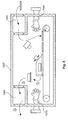
- Fig. 2 shows a possible structure of a manufacturing arrangement and a corresponding process flow.
- the substrate plate segments 10a, b, c ... are introduced from a right side in a horizontal direction of movement 11 in an input lock 100 and arrive in the same direction of movement 11 from the entrance lock 100 in a process chamber 110.
- the process chamber 110 is the in Fig. 1 arranged manufacturing section and finds the respect Fig. 1 explained manufacturing process instead. After corresponding generative production of the products in the process chamber 110, these pass through further movement along the direction of movement 11 in an outlet lock 120 and are thereby discharged from the process chamber.
- a favorable atmosphere for additive production in particular an inert gas atmosphere or an active gas atmosphere, can be maintained in the process chamber 110 and thereby the product quality can be ensured.
- Fig. 3 shows a second embodiment of a manufacturing section for additive manufacturing and a manufacturing section for the separation and removal of generatively produced products.
- a plurality of substrate plate segments 110a, b, c ... are arranged side by side in such a way that a coherent substrate plate is thereby provided.
- the upper surface of these provided by the substrate plate segments 110a, b, c ... substrate plate is inclined at an angle ⁇ to the horizontal, that this surface is at an angle 90 ° - ⁇ to the direction of gravity.
- a coating device 130 is arranged, which can cyclically reciprocate along a horizontal direction of movement 131.
- a powder layer of a powder reservoir which can be arranged on the coating device 130 or which can be arranged along the movement path 131 of the coating device 130, is applied in this manner.
- a powder layer can be applied above the substrate plate segments 110a, b, c ... which lies at an angle ⁇ to the upper surface of the substrate plate segments.
- each powder layer is selectively cured by selectively curing each coated layer by means of two radiation sources 140a, b formed as high-power lasers
- products 60a, b are built up generatively in layers on the substrate plate segments.
- respective partition walls 61a-d are constructed above the substrate plate segments by appropriately selective hardening of the layers. These partitions divide the powder bed above the substrate plate segments into several powder bed areas. In each powder bed area is one or more products arranged, which can be removed simultaneously.
- the substrate plate segments 110a, b, c ... are attached to an endless conveyor belt 120 and are moved continuously or discontinuously by means of this endless conveyor belt 120 in a conveying direction 111.
- the generative production of the products takes place by means of this conveying movement 111 and repeated application of powder layers by means of the coating device 130, followed by selective hardening of each applied layer.
- the powder coating device 130 moves along a direction of movement 131 that lies at an angle ⁇ 2 to the direction of movement 111 of the substrate plate segments.
- a production area B uncured powder material is removed by an extraction device from the area between two generatively produced partitions 61a-d and subsequently removed both the partitions and the generatively produced and finished in this area between the two partitions and products.
- the substrate plate segments are guided along a deflection roller in the lower strand of the conveyor belt 120 and run along this lower strand up to a second deflection roller, where they are again guided in the upper strand to a new coating with powder layers and generative production to be supplied by products.
- a sump 170 is provided to collect excess powder which falls off upon deflection of the substrate plate segments.
- individual products can be constructed generatively on a single substrate plate segment or a single product can also be constructed generatively on multiple substrate plate segments. It depends solely on the size of the substrate plate segments and the generatively produced products, whether multiple products on a substrate plate segment or a product on several substrate plate segments or one product per substrate plate segment will be produced. In particular, the use of supports can also produce a product on a single substrate plate segment, the dimensions of which are larger than the dimensions of the substrate plate segment itself.
- the angle ⁇ 1 or ⁇ 2 between the layer application direction and the surface of the substrate plate segments is smaller than the powder shaking angle of the applied powder, in order to achieve a stability of the applied powder bed against the action of gravity.
- the angle ⁇ 2 are also greater than this powder shaking angle are chosen, since the powder bed is stabilized by the partitions 61a-d and the powder layer layers themselves are applied horizontally and are.
- Fig. 4 shows a schematic representation of an alternative embodiment in which the angle ⁇ 3 between the plane in which the powder layer is applied and the surface of the substrate plate segments may be greater than the angle of powder shaking.
- the products 260a-c are also constructed generatively on substrate plate segments 210a-c, thereby producing a powder bed 250 above these substrate plate segments.
- the powder bed 250 is stabilized by means of a cover plate 280 running parallel to the substrate plate segments in the production section.
- the cover plate 280 in particular can move continuously with the substrate plate segments in order to prevent a relative movement between the powder bed and the cover plate 280.
- Fig. 5 shows a schematic representation of a manufacturing arrangement for the continuous production of generatively produced products.
- the embodiment according to Fig. 5 represents an alternative to the in Fig. 2 illustrated embodiment. Contrary to in Fig. 2 illustrated embodiment are in the in Fig. 5 illustrated embodiment, all required for generative production and removal of the products from the generative manufacturing process manufacturing sections within a process chamber 1030, which can be kept under a controlled atmosphere, in particular an inert gas or active gas atmosphere.
- a production process is arranged within the process chamber 1030, the basic system of which according to the manufacturing process Fig. 1 equivalent. But it should be understood that in the same way in Fig. 5 illustrated manufacturing arrangement Such that a manufacturing process according to Fig. 3 or Fig. 4 takes place in the process chamber.
- the process chamber 1030 has a first lock 1040, through which new, uncoated and not stocked with products substrate plates can be introduced and can be mounted on an endless conveyor belt.
- a working glove 1050 is arranged in a gas-tight manner in such a region, which makes it possible to receive substrate plates from the sluice 1040 and fix them on the endless conveyor belt.
- a second lock 1060 is arranged on the process chamber 1030. Through the lock 1060 substrate plates arranged thereon, finished products from the process chamber 1030 can be discharged. In order to carry out this process manually, a glove is again arranged in the area of the lock 1060, by means of which it is possible to reach into the process chamber 1030, detach the substrate plate segments together with products arranged thereon from the endless conveyor belt and through the lock 1060 out of the process chamber 1030 can be discharged.
Abstract
Description
Die Erfindung betrifft ein Verfahren zum Herstellen von Produkten mit individueller Geometrie, insbesondere Zahnersatz oder dentalen Hilfsteilen, mit den Schritten Herstellen mehrerer Produkte auf der Oberfläche einer Substratplatte mittels selektiven Aushärtens, insbesondere mittels selektiven Sinterns oder Schmelzens, bei dem das Material in aufeinanderfolgenden Schichten aufgetragen wird, nach jedem Schichtauftrag ein oder mehrere vorbestimmte Bereiche der aufgetragenen Schicht mittels einer energiereichen Strahlung selektiv ausgehärtet und mit einem oder mehreren Bereichen der darunter liegenden Schicht verbunden werden, wobei die vorbestimmten Bereiche anhand einer Querschnittsgeometrie des Produkts in der jeweiligen Schicht vorbestimmt werden. Ein weiterer Aspekt der Erfindung ist eine Vorrichtung zur Durchführung eines solchen Verfahrens.The invention relates to a method for producing products with individual geometry, in particular dentures or dental auxiliary parts, with the steps of producing a plurality of products on the surface of a substrate plate by means of selective curing, in particular by means of selective sintering or melting, in which the material is applied in successive layers in that, after each layer application, one or more predetermined regions of the applied layer are selectively cured by means of high-energy radiation and bonded to one or more regions of the underlying layer, the predetermined regions being predetermined based on a cross-sectional geometry of the product in the respective layer. Another aspect of the invention is a device for carrying out such a method.
Generative Fertigungsverfahren, d.h. Fertigungsverfahren, bei denen ein Material in einem additiven Herstellungsprozess zu einem individuellen Produkt geformt wird, finden ihre Anwendung im Bereich der Herstellung von Prototypen und haben inzwischen auch in der Produktherstellung, insbesondere bei der Anfertigung individuell geformter Produkte oder von Kleinstserien, ihre Anwendung gefunden. Aus
Neben einem solchen, für Zahnersatz besonders geeigneten selektivem Lasersinter- oder Laserschmelzverfahren (SLS, SLM) für metallische Pulver, können für andere Produkte auch andere generative Fertigungsverfahren geeignet sein, beispielsweise Verfahren, bei denen ein Granulat oder anderes festes Material durch einen hochenergetischen Strahl, wie beispielsweise einen Laserstrahl oder Elektronenstrahl gesintert oder geschmolzen und auf diese Weise verbunden und ausgehärtet wird, oder Verfahren, bei denen ein in fester oder flüssiger Form vorliegender Kunststoff durch einen hochenergetischen Strahl, wie beispielsweise einen Laser- oder gebündelten Lichtstrahl durch Photopolymerisation selektiv ausgehärtet wird.In addition to such, for dental prostheses particularly suitable selective laser sintering or laser melting process (SLS, SLM) for metallic powders, other generative manufacturing processes may be suitable for other products, such as processes in which a granulate or other solid material by a high-energy beam, such as For example, a laser beam or electron beam is sintered or melted and thus bonded and cured, or methods in which a solid or liquid form plastic is selectively cured by a high-energy beam, such as a laser or collimated light beam by photopolymerization.
Diese generativen Fertigungsverfahren arbeiten regelmäßig solcherart, dass auf einer Substratplatte aufeinanderfolgend Schichten des aushärtbaren Materials aufgetragen werden, beispielsweise indem die Substratplatte sukzessive und diskontinuierlich in ein flüssiges Bad des aushärtbaren Materials abgesenkt wird oder indem mittels einer Pulverauftragsvorrichtung sukzessive Schichten auf der Substratplatte übereinander aufgetragen werden. Nach jedem Schichtauftragsvorgang werden bestimmte Teile der Schicht selektiv ausgehärtet und auf diese Weise das Produkt schichtweise aufgebaut. Nach Fertigstellung des Produkts durch Aushärtung der letzten Schicht können nicht ausgehärtete Bereiche des Materials entfernt und häufig wiederverwendet werden. Das SLS oder SLM-Verfahren ist prinzipiell in
Ein grundsätzliches Problem der generativen Fertigungsverfahren ist die lange Zeitdauer, die zwischen der Erstellung der Fertigungsdaten und der Fertigstellung des Produkts vergeht. Es ist bekannt, auf einer Substratplatte mehrere Produkte gleichzeitig generativ aufzubauen, um auf diese Weise die Anzahl der in einer bestimmten Zeitspanne hergestellten Produkte zu erhöhen. Dieses Vorgehen ist insbesondere bei Produkten mit sehr kleinen Abmessungen in Bezug auf die Abmessungen der Substratplatte sinnvoll und führt zu einer wirksamen Steigerung der Produktivität.A fundamental problem of generative manufacturing processes is the long time that elapses between the creation of the manufacturing data and the completion of the product. It is known to generate several products on a substrate plate at the same time generatively, in order to increase in this way the number of products produced in a certain period of time. This approach is particularly useful for products with very small dimensions in terms of the dimensions of the substrate plate and leads to an effective increase in productivity.
Aus
Aus
Aus
Während mit den bekannten Fertigungsverfahren und -vorrichtungen nur individuelle Produkte, deren Größe etwa die Substratplatte einnehmen, in einer sowohl produktiven Fertigungsweise als auch mit einer für jedes Einzelprodukt vertretbaren Gesamtfertigungsdauer hergestellt werden können, ist es für Produkte, deren Abmessungen weitaus kleiner sind als die Substratplatte, nur möglich, die Produktivität durch gemeinsame Fertigung mehrerer Produkte auf einer Substratplatte zu sichern, die Fertigungszeit für ein einzelnes Produkt kann jedoch in diesem Fall nicht auf eine wünschenswert kleine Zeitspanne gebracht werden, sondern wird durch die Erstellung von Fertigungsdaten aller auf der Substratplatte herzustellenden Produkte und die hierauf folgende gleichzeitige Fertigung aller Produkte erhöht.While only individual products whose size occupy about the substrate plate, can be produced in a production both productive manner and with a total production time acceptable for each individual product with the known manufacturing processes and devices, it is for products whose dimensions are much smaller than the substrate plate While it is only possible to ensure productivity by co-manufacturing multiple products on a substrate plate, the manufacturing time for a single product can not be reduced to a desirably small amount of time in this case, but rather by providing manufacturing data of all products to be fabricated on the substrate plate and the subsequent simultaneous production of all products increased.
Ein weiteres Problem bei der generativen Fertigung von kleinen Produkten, wobei hierunter Produkte verstanden werden sollen, deren Grundfläche kleiner, insbesondere um mindestens eine Größenordnung kleiner ist als die Oberfläche der Substratplatte, besteht darin, dass in vielen Anwendungsbereichen mit individuellen Produktgeometrien die generative Fertigung als Auftragsfertigung erfolgt, wie beispielsweise bei der Herstellung von Zahnersatz in zahntechnischen Laboren. In diesem Fall kommen die einzelnen Aufträge typischerweise nicht gleichzeitig, sondern zeitversetzt beim Benutzer der Fertigungsvorrichtung an. Um in diesem Fall eine hohe Produktivität und Auslastung der Anlage zu erzielen, muss der Benutzer mehrere Aufträge bündeln, um die in den gebündelten Aufträgen enthaltenen Produkte gleichzeitig auf einer Substratplatte zu fertigen. Dies erzeugt jedoch, insbesondere für den zuerst eingegangenen Auftrag, eine erhebliche Verzögerung zwischen Auftragseingang und Fertigstellung des Produkts. Will der Benutzer hingegen jeden Auftrag in der kürzestmöglichen Zeit bedienen und das entsprechende individuelle Produkt fertigen, so ist er gezwungen, den Fertigungsprozess auf einer Substratplatte mit lediglich einem oder einigen wenigen Produkten durchzuführen, was zu einer insgesamt geringen Auslastung der Fertigungsvorrichtung und niedriger Produktivität führt.Another problem in the generative production of small products, which are to be understood by products whose footprint is smaller, in particular by at least an order of magnitude smaller than the surface of the substrate plate, is that in many applications with individual product geometries, the additive manufacturing as contract manufacturing takes place, such as in the manufacture of dental prostheses in dental laboratories. In this case, the individual orders typically do not arrive at the same time as the user of the production device, but with a time delay. In this case, to achieve high productivity and utilization of the plant, the user must bundle several orders in order to simultaneously manufacture the products contained in the bundled orders on a substrate plate. However, this creates a significant delay between receipt of the order and completion of the product, especially for the first order placed. If, on the other hand, the user wishes to operate each order in the shortest possible time and manufacture the corresponding individual product, then he is forced to carry out the production process on a substrate plate with only one or a few products, resulting in an overall low utilization of the manufacturing device and low productivity.
Es ist eine Aufgabe der Erfindung, die bekannten Fertigungsverfahren dahingehend weiterzuentwickeln, dass auch bei Produkten, deren Abmessungen im Verhältnis zur Substratplattenabmessung klein sind, sowohl eine hohe Produktivität als auch eine geringe Fertigungsdauer für jedes einzelne Produkt zu erreichen. Es ist ein weiteres Ziel der Erfindung, ein Fertigungsverfahren und eine Fertigungsvorrichtung bereitzustellen, welche den Zeitraum zwischen Auftragseingang für ein individuell zu fertigendes, kleines Produkt und Fertigstellung des Produkts zu verkürzen, ohne hierbei die Produktivität des Fertigungsverfahrens bzw. der Fertigungsvorrichtung nachteilig zu beeinflussen.It is an object of the invention to further develop the known manufacturing processes in such a way that even for products whose dimensions are small in relation to the substrate plate dimension, both a high productivity and a short production time for each individual product are achieved. It is a further object of the invention to provide a manufacturing method and apparatus which can reduce the time between receipt of order for an individually manufactured small product and completion of the product without adversely affecting the productivity of the manufacturing process or the manufacturing apparatus.
Diese Aufgaben werden erfindungsgemäß mit einem Verfahren der eingangs genannten Art gelöst, bei dem die aufeinanderfolgenden Schichten in Schichtebenen aufgetragen werden, die schräg zu der Oberfläche der Substratplatte ausgerichtet sind.These objects are achieved according to the invention with a method of the type mentioned above, in which the successive layers are applied in layer planes which are aligned obliquely to the surface of the substrate plate.
Auch bei dem erfindungsgemäßen Verfahren werden mehrere Produkte gleichzeitig auf der Oberfläche einer Substratplatte durch einen selektiven Aushärtungsvorgang schichtweise hergestellt. Dabei ist zu verstehen, dass bei dem erfindungsgemäßen Verfahren nicht notwendigerweise eine Substratplatte in klassischer Bauweise zum Einsatz kommen muss, also eine kreisrunde oder quadratische oder rechteckige einstückige Substratplatte. Stattdessen kann die erfindungsgemäße Substratplatte beispielsweise als Substratförderband bereitgestellt sein oder als eine aus mehreren Segmenten zusammengesetzte Substratplatte, bei der sich diese Substratplattensegmente beispielsweise entlang einer Richtung aneinanderreihen.In the method according to the invention, several products are simultaneously produced in layers on the surface of a substrate plate by a selective curing process. It should be understood that in the method according to the invention does not necessarily have a substrate plate in the classical design must be used, so a circular or square or rectangular one-piece substrate plate. Instead, the substrate plate according to the invention may be provided, for example, as a substrate conveyor belt or as a substrate plate composed of a plurality of segments, in which these substrate plate segments, for example, line up along one direction.
Das erfindungsgemäße Verfahren zeichnet sich dadurch aus, dass die Schichten des aushärtbaren Materials nicht solcherart aufgetragen werden, dass die Schichtebene parallel zu der Oberfläche der Substratplatte ausgerichtet ist, sondern stattdessen so aufgetragen werden, dass die Schichtebene schräg, d.h. unter einem Winkel zwischen 0 und 90° zu der Oberfläche der Substratplatte ausgerichtet ist. Durch diesen schrägen Schichtauftrag auf der Substratplatte wird erreicht, dass die insgesamt deshalb eines Ortes der Substratplatte angeordnete Materialbettdicke nicht an jeder Stelle gleich ist, sondern unterschiedlich. Insbesondere vergrößert sich die Dicke des aufgetragenen Materialbettes ausgehend von einem Bereich, in dem genau eine Schichtdicke auf der Substratplatte aufliegt, kontinuierlich bis in einen Bereich, in dem die maximal auftragbaren Schichten oberhalb der Substratplatte aufgelegt sein können. Dabei ist zu verstehen, dass eine Materialschicht stets über einen Bereich der Substratplatte aufgetragen wird, der zwar nicht notwendigerweise die gesamte Substratplatte überstreichen muss, aber in der Regel einen Bereich überstreicht, in dem mehrere der Produkte, die auf der Substratplatte aufgebaut werden, angeordnet sind.The inventive method is characterized in that the layers of the curable material are not applied such that the layer plane is aligned parallel to the surface of the substrate plate, but instead be applied so that the layer plane oblique, ie at an angle between 0 and 90 ° is aligned with the surface of the substrate plate. As a result of this oblique layer application on the substrate plate, it is achieved that the material bed thickness arranged overall for a location of the substrate plate is not the same at every location but different. In particular, the thickness of the applied material bed, starting from a region in which exactly one layer thickness rests on the substrate plate, increases continuously to a region in which the maximum applicable Layers can be placed above the substrate plate. It is to be understood that a layer of material is always applied over a portion of the substrate plate which does not necessarily have to cover the entire substrate plate, but typically sweeps over an area where several of the products built up on the substrate plate are located ,
Durch den erfindungsgemäß schrägen Auftrag der Materialschichten können auf der Substratplatte mit dem erfindungsgemäßen Verfahren mehrere kleine Produkte gleichzeitig aufgebaut werden, die aber in unterschiedlichen Fertigungsstadien sind. So kann in einem Bereich, in dem durch den schrägen Auftrag der Schicht erst eine einzige Schicht auf der Substratplatte aufliegt, ein neues Produkt begonnen werden, wohingegen in einem Bereich, in dem die schräg aufgetragene Schicht auf bereits mehrere zuvor aufgetragene Schichten aufgetragen wird, ein Produkt fertig gestellt werden. Zwischen diesen beiden Endpunkten können ein oder mehrere Produkte in einem Fertigungsstadium zwischen Beginn und Ende, d.h. mit beispielsweise 50 oder 100 bereits aufgetragenen und selektiv ausgehärteten Schichten angeordnet sein.As a result of the oblique application of the material layers according to the invention, several small products can be constructed simultaneously on the substrate plate by the method according to the invention, but these are in different stages of production. Thus, in a region in which only a single layer rests on the substrate plate due to the oblique application of the layer, a new product can be started, whereas in a region in which the obliquely applied layer is already applied to a plurality of previously applied layers Product to be completed. Between these two endpoints, one or more products may be in a production stage between start and end, i. be arranged with, for example, 50 or 100 already applied and selectively cured layers.
Das erfindungsgemäße Fertigungsverfahren ermöglicht es hierdurch, unmittelbar nach Fertigstellung der Fertigungsdaten für ein Produkt dessen Fertigung zu beginnen und dieses Produkt dann nach Fertigstellung aus dem Fertigungsprozess zu entnehmen, ohne hierbei darauf warten zu müssen, dass Fertigungsdaten von anderen Produkten fertig gestellt worden sind oder gar andere Produkte fertig gestellt worden sind. Dabei ist zu verstehen, dass in gleicher Weise wie ein quasi kontinuierlicher Fertigungsbeginn aufeinanderfolgender individueller Produkte beim erfindungsgemäßen Verfahren realisiert wird, eine quasi kontinuierliche Entnahme von einzelnen fertig gestellten Produkten bewirkt werden kann, um die Fertigungszeit für jedes einzelne Produkt zu minimieren. Mit dem erfindungsgemäßen Verfahren wird es somit möglich, auch Produkte kleiner Abmessungen in einer solchen Fertigungszeit herzustellen, die nur durch die für die einzelnen Schichtaufträge und deren Aushärten benötigten Prozessschritte erforderlich ist und trotzdem eine hohe Produktivität durch eine parallele Fertigung von mehreren Produkten zu erhalten, indem durch einen schrägen Pulverauftrag in Bezug auf die Substratplatte es ermöglicht wird, Produkte in unterschiedlichen Fertigungsstadien auf einer Substratplatte und mit einem gemeinsamen Schichtauftrag herzustellen. Der Pulverauftrag erfolgt vorzugsweise entlang einer Dichtung, die der Schwerkraft bedingten Fließrichtung des Pulvers in der Schicht entgegengesetzt ist, wenn die Schicht schräg zu Horizontalen verläuft.The manufacturing method according to the invention thus makes it possible, immediately after completion of the manufacturing data for a product to begin production and then remove this product after completion of the manufacturing process, without having to wait for manufacturing data from other products have been completed or even others Products have been completed. It should be understood that in the same way as a quasi-continuous start of production of successive individual products is realized in the inventive method, a quasi-continuous removal of individual finished products can be effected in order to minimize the production time for each product. With the method according to the invention it is thus possible to produce even products of small dimensions in such a production time, which is required only by the process steps required for the individual layer jobs and their curing and still obtain high productivity by a parallel production of several products by by an oblique powder application with respect to the substrate plate, it is possible to produce products in different stages of production on a substrate plate and with a common layer order. The powder is preferably applied along a seal which is opposite to the gravity flow direction of the powder in the layer when the layer is oblique to horizontal.
Gemäß einer ersten bevorzugten Ausführungsform ist vorgesehen, dass die aufeinanderfolgenden Schichten parallel zueinander aufgetragen werden. Das parallele Auftragen der Schichten ermöglicht eine gleichbleibende Schichtdicke entlang des gesamten Auftragsvorgangs und eine somit einfache Prozesssteuerung. Dabei ist zu verstehen, dass nicht notwendigerweise jede der Schichten die gleiche Dicke erhalten muss, insbesondere kann die Schichtdicke in Abhängigkeit der Produktgeometrie größer oder kleiner gewählt werden, um die durch die Schichtdicke vorgegebene geometrische Auflösung der Produktgeometrie anzupassen.According to a first preferred embodiment it is provided that the successive layers are applied parallel to each other. The parallel application of the layers allows a constant layer thickness along the entire application process and thus a simple process control. It should be understood that not necessarily each of the layers must receive the same thickness, in particular, the layer thickness depending on the product geometry can be selected larger or smaller, to adjust the predetermined by the layer thickness geometric resolution of the product geometry.
Gemäß einer weiteren bevorzugten Ausführungsform ist vorgesehen, dass jede der aufeinanderfolgenden Schichten in einem Winkel aufgetragen wird, der kleiner oder gleich dem Schüttwinkel des Materials auf der Substratplatte ist. Grundsätzlich ist hierbei der Winkel, in dem eine Schicht aufgetragen wird, als der Winkel zu verstehen, der als spitzer Winkel zwischen der Ebene der Oberfläche der Substratplatte und der Ebene der aufgetragenen Schicht eingeschlossen ist. Unter dem Schüttwinkel des Materials ist derjenige Winkel zu verstehen, der sich zwischen den Seitenflächen eines Materialberges und einer Grundfläche einstellt, auf den das Material im Wege einer Schüttung aufgetragen wird. Der Schüttwinkel eines Materials ist umso kleiner, je größer die Gleitfähigkeit des Materials auf der Oberfläche, auf welche es aufgetragen wird, ist und je höher die Gleitfähigkeit des Materials in sich selbst, also beispielsweise die Gleitfähigkeit der einzelnen Pulverkörner eines pulverförmigen Materials untereinander ist. Wenn die aufeinanderfolgenden Schichten beim erfindungsgemäßen Verfahren in einem Winkel aufgetragen werden, der kleiner als der Schüttwinkel ist oder dem Schüttwinkel entspricht, so kann auf diese Weise sichergestellt werden, dass eine aufgetragene Schicht nicht durch Abrutschen von Schichtteilen oder einzelnen Materialpartikeln oder dgl. ihre aufgetragene geometrische Form nachträglich verliert. Stattdessen wird bei der Wahl eines solchen Auftragswinkels sichergestellt, dass die Schicht als freie Schüttung stabil liegen bleibt und folglich in einfacher und geometrisch präziser Weise selektiv ausgehärtet werden kann.According to another preferred embodiment, it is provided that each of the successive layers is applied at an angle which is less than or equal to the angle of repose of the material on the substrate plate. Basically, in this case, the angle at which a layer is applied is to be understood as the angle enclosed as an acute angle between the plane of the surface of the substrate plate and the plane of the applied layer. The angle of repose of the material is to be understood as that angle which is established between the side surfaces of a material mountain and a base area onto which the material is applied by way of a bed. The angle of repose of a material is the smaller, the greater the lubricity of the material on the surface to which it is applied, and the higher the lubricity of the material in itself, so for example, the lubricity of the individual powder grains of a powdery material with each other. If the successive layers in the method according to the invention are applied at an angle which is smaller than the angle of repose or corresponds to the angle of repose, then it can be ensured in this way that a layer applied does not lose its applied geometric shape due to slippage of layer parts or individual material particles or the like Form loses later. Instead, when choosing such an angle of application, it is ensured that the layer remains stable as a free bed and consequently can be selectively cured in a simple and geometrically precise manner.
Um den Schüttwinkel positiv zu beeinflussen, das heißt einen möglichst großen Schüttwinkel zu erzielen und folglich auch die Schichten in einem möglichst großen Winkel auftragen zu können, kann einerseits die Oberfläche der Substratplatte in spezifischer Weise bearbeitet werden, beispielsweise durch Polieren, Schleifen, Läppen, Honen, Beizen, Trovalieren, Sandstrahlen, Fräsen, Drehen und andere Bearbeitungsverfahren. Hierbei kann das Fertigungsverfahren vorzugsweise solcher Art eingestellt werden, dass eine für einen großen Schüttwinkel günstige Rauheit der Substratplatte erreicht wird, die typischerweise im Bereich von 0,5µm bis 50µm Rz (gemittelte Rauhtiefe nach DIN EN ISO 4287:1998) liegt, oder typischerweise im Bereich von 0,1 µm bis 10 µm Ra (Mittenrauhwert) liegt oder im Bereich von 0,04 mm bis 1,3 mm RSm (mittlere Rillenbreite nach DIN EN ISO 4287:1998 bei periodischen Profilen, wie sie beispielsweise beim Fräsen zu finden ist), liegt. Dabei ist zu verstehen, dass diese bevorzugten Rauhigkeitsbereiche der Substratplatte für typische Pulver vorteilhaft sind, die für das selektive Lasersintern oder selektive Laserschmelzen zu Einsatz kommen, insbesondere um hierdurch formgetreu und präzise kleine Teile wie dentale Implantate oder Hilfsteile herzustellen.In order to positively influence the angle of repose, that is to achieve the greatest possible angle of repose and consequently to be able to apply the layers in the largest possible angle, on the one hand the surface of the substrate plate can be processed in a specific manner, for example by polishing, grinding, lapping, honing , Pickling, trovaling, sandblasting, milling, turning and other machining processes. In this case, the production method can preferably be adjusted in such a way that a roughness of the substrate plate that is favorable for a large angle of repose is achieved typically in the range of 0.5μm to 50μm Rz (average roughness to DIN EN ISO 4287: 1998), or typically in the range of 0.1μm to 10μm Ra (average roughness), or in the range of 0.04mm to 1 , 3 mm RSm (average groove width according to DIN EN ISO 4287: 1998 for periodic profiles, as found, for example, in milling). It should be understood that these preferred roughness ranges of the substrate plate are advantageous for typical powders used for selective laser sintering or selective laser melting, in particular to thereby faithfully and precisely fabricate small parts such as dental implants or auxiliary parts.
Vorzugsweise kann weiterhin die Oberfläche des Pulvers mittels Polieren, Schleifen, Beizen, Sandstrahlen, Trovalieren oder Beschichten bearbeitet werden, um den Schüttwinkel im oben genannten Sinne positiv zu beeinflussen.Preferably, furthermore, the surface of the powder can be processed by means of polishing, grinding, pickling, sandblasting, trovaling or coating in order to positively influence the angle of repose in the above-mentioned sense.
Sofern flüssige Materialien als aushärtbares Material zum Einsatz kommen, kann die Benetzbarkeit der Oberfläche positiv beeinflusst werden durch eine chemische, optische oder mechanische Oberflächenbehandlung, wie beispielsweise Laserstrahlaufrauhen.If liquid materials are used as a curable material, the wettability of the surface can be positively influenced by a chemical, optical or mechanical surface treatment, such as laser beam roughening.
Ein weiterer Ansatzpunkt, um den Schüttwinkel im oben genannten Sinne positiv zu beeinflussen ist die genannte Granulierung des Materials. Dies kann beispielsweise erfolgen, in dem geschmolzenes Metall in dünnem Strahl in kaltes Wasser unter beständigem Umrühren gegossen wird um so granuliertes Material zu erhalten. Andere, leicht schmelzbare Metalle kann man granulieren, indem man sie in eine innenwändig stark mit Kreide ausgestrichene Büchse gießt und nach Verschließen der Büchse schüttelt, bis das Metall erkaltet ist.Another starting point for positively influencing the angle of repose in the aforementioned sense is the mentioned granulation of the material. This may be done, for example, by pouring molten metal in a thin stream into cold water with constant stirring to obtain granulated material. Other, easily fusible metals can be granulated by pouring them into a rifle which is heavily chalked internally and, after closing the can, shaking until the metal has cooled.
Dabei ist es für das erfindungsgemäße Verfahren und die erfindungsgemäße Vorrichtung insbesondere vorteilhaft, wenn das Material solcher Art aufbereitet wird, dass eine gute Verbindung, Verklammerung oder dergleichen der Materialpartikel untereinander und eine entsprechend schlechte Gleitfähigkeit der Partikel aneinander hergestellt wird, das heißt die Partikel sollten insbesondere eine von der Kugelform abweichende äußere Gestalt haben, zugleich eine hohe Oberflächenrauhigkeit aufweisen und insbesondere vorzugsweise weiterhin von insgesamt unregelmäßiger Gestalt sein. Die Gleitfähigkeit des Materials beeinflusst gleichzeitig dessen Eignung, in dünnen Schichten aufgetragen zu werden und eine dichte Packung mit geringen Hohlraumanteilen einzunehmen. Das Material muss also solcherart aufbereitet werden, dass zum einen ein maximaler Schüttwinkel erreicht wird. Andererseits muss das Material in der dem Prozess angepassten Schichtdicken auftragbar sein und eine möglichst hohe Packungsdichte erzielen, da diese in direktem Zusammenhang mit der erzielten Dichte des hergestellten Produkts steht. Typische Schichtdicken liegen zwischen 5 µm und 200 µm.It is particularly advantageous for the inventive method and the device according to the invention, when the material is processed such that a good connection, clamping or the like of the material particles to each other and a correspondingly poor lubricity of the particles is made to each other, that is, the particles should in particular have a different shape from the spherical outer shape, at the same time have a high surface roughness and in particular preferably continue to be of an overall irregular shape. The lubricity of the material also affects its ability to be applied in thin layers and to occupy a dense packing with low void fraction. The material must therefore be processed in such a way that on the one hand a maximum angle of repose is achieved. On the other hand, the material must be adapted in the process Layer thicknesses to be applied and achieve the highest possible packing density, since this is directly related to the achieved density of the product produced. Typical layer thicknesses are between 5 μm and 200 μm.
Gemäß einer weiteren bevorzugten Ausführungsform ist vorgesehen, dass die Substratplatte zwischen zwei aufeinanderfolgenden Schichtauftragsvorgängen mit einer Richtungskomponente senkrecht zur Ebene, in der die Schicht aufgetragen wird, verfahren wird. Unter einer Richtungskomponente ist in diesem Zusammenhang ein Bewegungsanteil zu verstehen, der gemeinsam mit anderen, in anderen Richtungen stattfindenden Bewegungsanteilen die Gesamtbewegung ausmacht. Durch einen Bewegungsanteil senkrecht zur Ebene des Schichtauftrags kann ein Vorschub erzeugt werden, welcher einen nachfolgenden Schichtauftrag ermöglicht, ohne dass hierfür die Schichtauftragsvorrichtung in anderer Weise als parallel zur Ebene des Schichtauftrags bewegt werden muss. Insbesondere kann diese Richtungskomponente bewirkt werden, indem die Substratplatte in einer Richtung parallel zur Oberfläche der Substratplatte bewegt wird. Eine solche Bewegung enthält aufgrund des Winkels zwischen dieser Oberfläche und der Ebene des Schichtauftrags die für den beim nacheinander folgenden Schichtauftrag erforderlichen Vorschub erforderliche Richtungskomponente.According to a further preferred embodiment, it is provided that the substrate plate is moved between two successive layer application processes with a directional component perpendicular to the plane in which the layer is applied. In this context, a directional component is to be understood as a proportion of movement which, together with other movement parts taking place in other directions, makes up the total movement. By a proportion of movement perpendicular to the plane of the layer order, a feed can be generated, which allows a subsequent layer application, without the need for the layer application device must be moved in a different way than parallel to the layer of the layer. In particular, this directional component can be effected by moving the substrate plate in a direction parallel to the surface of the substrate plate. Due to the angle between this surface and the plane of the layer application, such a movement contains the directional component required for the feed required for successive layer application.
Es ist insbesondere weiter bevorzugt, dass die Oberfläche der Substratplatte in dem Bereich, in dem die Schichten aufgetragen werden, horizontal in Bezug auf die Schwerkraftrichtung verläuft. In diesem Fall wird die Schicht in einer Ebene aufgetragen, die schräg zur Horizontalen verläuft und die Schichtauftragsvorrichtung muss für einen solchen, schräg zur Horizontalen verlaufenden Schichtauftrag ausgebildet sein.In particular, it is further preferred that the surface of the substrate plate in the region in which the layers are applied is horizontal with respect to the direction of gravity. In this case, the layer is applied in a plane which runs obliquely to the horizontal and the layer application device must be designed for such, oblique to the horizontal layer application.
Bei einer hierzu alternativen, bevorzugten Ausführungsform ist vorgesehen, dass die Oberfläche der Substratplatte in dem Bereich, in dem die Schichten aufgetragen werden, schräg zu Horizontalen in Bezug auf die Schwerkraftrichtung verläuft. Indem die Oberfläche der Substratplatte im Schichtauftragsbereich schräg zur Horizontalen verläuft, wird es ermöglicht, dass die Schicht in einer horizontalen Ebene aufgetragen wird. Die Schichtauftragsvorrichtung kann entsprechend für eine Bewegung in einer horizontalen Ebene ausgebildet sein. Dabei ist zu verstehen, dass auch dann, wenn die Substratplatte schräg zur Horizontalen verläuft, ein auch schräg zur Horizontalen verlaufender Materialauftrag vorgenommen werden kann und die Materialauftragsvorrichtung entsprechend ausgebildet sein kann.In an alternative, preferred embodiment, it is provided that the surface of the substrate plate in the region in which the layers are applied extends obliquely to the horizontal with respect to the direction of gravity. By the surface of the substrate plate in the layer application area is inclined to the horizontal, it is possible that the layer is applied in a horizontal plane. The layer application device can be designed accordingly for movement in a horizontal plane. It should be understood that even if the substrate plate is oblique to the horizontal, a running obliquely to the horizontal material order can be made and the material application device can be designed accordingly.
Bei den beiden vorgenannten Ausführungsformen ist es weiterhin vorzugsweise vorgesehen, dass die aufgetragenen Schichten in einen benachbart zu einem Fertigungsabschnitt, in dem die Schichten aufgetragen werden, liegenden, als Haltebereich ausgebildeten, benachbarten Fertigungsabschnitt verfahren werden, in dem eine durch die aufgetragenen Schichten gebildeten oberen Fläche des aufgetragenen Materials durch eine parallel zur Oberfläche der Substratplatte verlaufende untere Fläche einer Deckplatte bedeckt und gestützt wird. Bei dieser Ausgestaltung erfolgt in einem bestimmten Fertigungsabschnitt, in dem die Höhe des Materials oberhalb der Substratplatte eine bestimmte Höhe erreicht hat, eine Stützung des Materials durch einerseits die Substratplatte und andererseits eine Deckplatte. Der Abstand zwischen Substratplatte und Deckplatte entspricht dabei der maximalen Höhe des Schichtbettes, also der Anzahl der Schichten multipliziert mit der Schichtdicke. Durch das Bereitstellen einer solchen Deckplatte kann das Material in einer günstigen Weise auf der Substratplatte stabilisiert werden und hierdurch der schräge Schichtauftrag in geometrisch präziser und reproduzierbarer Weise bewerkstelligt werden. Die Deckplatte kommt hierbei jeweils mit den von der Substratplatte weg weisenden Endbereichen der Materialschichten in Kontakt und stützt diese ab. Dabei ist zu verstehen, dass die Deckplatte auch in Form eines Endlosförderbandes oder einer sich mitbewegenden Platte ausgeführt sein kann, die sich synchron zur Bewegung der Substratplatte bewegt. Auf diese Weise wird eine Relativbewegung zwischen dem aufgetragenen Material und der Deckplatte vermieden, welche andernfalls eine Störung der Gleichmäßigkeit des Schichtauftrags im Randbereich zur Deckplatte zur Folge haben könnte.In the two aforementioned embodiments, it is further preferably provided that the applied layers are moved into a neighboring production section lying adjacent to a production section, in which the layers are applied, in the form of a holding region, in which an upper surface formed by the applied layers of the applied material is covered and supported by a parallel to the surface of the substrate plate extending lower surface of a cover plate. In this embodiment, in a certain manufacturing section, in which the height of the material above the substrate plate has reached a certain height, a support of the material by on the one hand the substrate plate and on the other hand, a cover plate. The distance between substrate plate and cover plate corresponds to the maximum height of the bed layer, ie the number of layers multiplied by the layer thickness. By providing such a cover plate, the material can be stabilized in a favorable manner on the substrate plate and thereby the oblique layer application can be accomplished in a geometrically precise and reproducible manner. In this case, the cover plate comes into contact with the end regions of the material layers pointing away from the substrate plate and supports them. It should be understood that the cover plate can also be designed in the form of an endless conveyor belt or a moving plate, which moves synchronously with the movement of the substrate plate. In this way, a relative movement between the applied material and the cover plate is avoided, which could otherwise result in a disturbance of the uniformity of the layer application in the edge region to the cover plate.
Gemäß einer weiteren bevorzugten Ausführungsform ist die Oberfläche der Substratplatte in eine erste Oberfläche eines ersten Substratplattensegments und zumindest eine weitere Oberfläche eines weiteren Substratplattensegments unterteilt. Bei dieser Fortbildung wird die Substratplatte in zwei oder mehrere benachbarte Substratplattensegmente unterteilt. Unter einem Substratplattensegment ist hierbei ein fertigungstechnisch separater Abschnitt der Substratplatte zu verstehen, der alleinig aufgrund von Steuerungsdaten des Schichtauftrags und der Aushärtefolge definiert sein kann. In diesem Fall stellt ein Substratplattensegment den Bereich der Substratplatte dar, auf dem ein oder mehrere Produkte gefertigt werden, die zeitgleich von der Substratplatte entnommen werden können, da sie quasi zeitgleich begonnen und fertig gestellt werden. Unter einem Substratplattensegment kann insbesondere aber auch ein physikalisch separates Bauteil verstanden werden. In diesem Fall setzt sich die Substratplatte durch mehrere aneinander gefügte Segmente zusammen. Die Segmente können in diesem Fall ebenfalls dazu genutzt werden, um auf jeweils einem Segment eines oder mehrere Produkte aufzubauen, die quasi zeitgleich begonnen und fertig gestellt werden und dann von dem Substratplattensegment abgelöst werden können.According to a further preferred embodiment, the surface of the substrate plate is subdivided into a first surface of a first substrate plate segment and at least one further surface of a further substrate plate segment. In this development, the substrate plate is divided into two or more adjacent substrate plate segments. In this case, a substrate plate segment is to be understood as a production-technically separate section of the substrate plate which can be defined solely on the basis of control data of the layer application and the curing sequence. In this case, a substrate plate segment represents the area of the substrate plate on which one or more products are manufactured, which can be removed from the substrate plate at the same time, since they are started and completed almost simultaneously. In particular, however, a substrate plate segment can also be understood as meaning a physically separate component. In this case, the substrate plate is composed by a plurality of segments joined together. The segments can also do this in this case can be used to build one or more products on each segment, which can be started and completed almost simultaneously and then detached from the substrate plate segment.
Dabei ist es insbesondere bevorzugt, wenn die Substratplattensegmente lösbar miteinander oder lösbar mit einem Grundträger verbunden sind und jedes Substratplattensegment nach Herstellen eines oder mehrere Produkte auf seiner Oberfläche von einem benachbarten Substratplattensegment oder dem Grundträger gelöst wird, um das/die darauf befindliche(n) Produkt(e) weiteren Bearbeitungsschritten zuzuführen. Mit dieser Fortbildung wird es möglich, jedes Substratplattensegment aus der Fertigungsvorrichtung herauszunehmen, um die darauf befindlichen, fertig gestellten Produkte weiteren Bearbeitungsschritten zuzuführen. Solche weiteren Bearbeitungsschritte können beispielsweise ein sorgfältiges Abtrennen des Produkts von dem Substratplattensegment eine spanende Nachbearbeitung, ein nachträgliches Aushärten und dgl. sein.In this case, it is particularly preferred if the substrate plate segments are detachably connected to each other or detachably connected to a base carrier and each substrate plate segment is detached after producing one or more products on its surface from an adjacent substrate plate segment or the base support to the / s thereon product (s) (e) to supply further processing steps. With this development, it becomes possible to remove each substrate plate segment from the manufacturing apparatus to supply the finished products thereon to further processing steps. Such further processing steps may include, for example, thoroughly separating the product from the substrate plate segment, a post-machining, post-curing and the like.
Noch weiter ist es dabei insbesondere bevorzugt, wenn die Substratplattensegmente in dem Fertigungsabschnitt, in dem die Schichten aufgetragen werden, so nebeneinander bereitgestellt werden, dass zwischen den Substratplattensegmenten kein Material hindurchtreten kann. Die solcherart durchgeführte Bereitstellung der Substratplattensegmente ist insbesondere vorteilhaft, wenn mit einer einzigen Schichtauftragsvorrichtung Schichten über mehrere Substratplattensegmente hinweg in einem Arbeitsgang aufgetragen werden. In diesem Fall wird verhindert, dass Material aus einem Schichtauftrag zwischen den Substratplattensegmenten hindurchtreten kann, was einerseits unerwünschten Materialverlust und andererseits eine geometrische Beeinflussung der Schichtdicke und des Schichtverlaufs haben könnte. Dies kann beispielsweise erreicht werden, indem die Substratplattensegmente mit zueinander kongruenten Kantenabschnitten unmittelbar aneinander anliegen oder indem eine entsprechende separate Dichtung zwischen zwei Substratplattensegmenten angeordnet ist.Still further, it is particularly preferred if the substrate plate segments in the manufacturing section in which the layers are applied are provided next to one another so that no material can pass between the substrate plate segments. The provision of the substrate plate segments carried out in this way is particularly advantageous if layers are applied over a plurality of substrate plate segments in a single operation with a single layer application device. In this case, it is prevented that material from a layer application can pass between the substrate plate segments, which on the one hand could have undesired loss of material and, on the other hand, a geometrical influence on the layer thickness and the course of the layer. This can be achieved, for example, by the substrate plate segments abutting directly against each other with mutually congruent edge portions or by a corresponding separate seal between two substrate plate segments is arranged.
Noch weiter ist es bevorzugt, dass die Substratplattensegmente als Segmente einer Endlosfördervorrichtung ausgebildet sind. Die Substratplattensegmente können beispielsweise an einem Endlosförderband befestigt sein oder solcherart miteinander verbunden sein, dass sie in Gestalt einer Gliederkette ein solches Endlosförderband bilden. In diesem Fall können die Substratplattensegmente in aufeinander folgender Weise entlang eines Obertrums und eines Untertrums bewegt werden, wobei während der Bewegung entlang des Obertrums der Schichtauftrag und die selektive Schichtaushärtung erfolgt. Die Entfernung von nicht ausgehärtetem, aufgetragenem Material aus dem Zwischenraum zwischen den hergestellten Produkten und die Entnahme der Produkte kann ebenfalls im Bereich des Obertrums erfolgen, beispielsweise durch entsprechende Absaugeinrichtungen bzw. mechanische Trennvorrichtungen. Es ist aber in gleicher Weise auch möglich, die Entfernung nicht ausgehärteten Materials im Bereich des Untertrums oder bei Übergang vom Obertrum in den Untertrum erfolgen zu lassen, beispielsweise schwerkraftbedingt und die fertig gestellten Produkte dann entweder mitsamt eines Substratplattensegments oder unmittelbar vom Substratplattensegment im Bereich des Untertrums abzunehmen.Still further, it is preferable that the substrate plate segments are formed as segments of an endless conveying device. The substrate plate segments may for example be attached to an endless conveyor belt or connected to each other in such a way that they form such an endless conveyor belt in the form of a link chain. In this case, the substrate plate segments may be moved in succession along an upper run and a lower run, wherein during movement along the upper run the layer application and the selective layer cure he follows. The removal of uncured, applied material from the gap between the products produced and the removal of the products can also be done in the area of the upper run, for example by appropriate suction or mechanical separation devices. However, it is also possible in the same way, the removal of uncured material in the area of the lower strand or at the transition from the upper strand done in the lower strand, for example due to gravity and the finished products then either together with a substrate plate segment or directly from the substrate plate segment in the region of the lower strand to decrease.
Gemäß einer weiteren bevorzugten Ausführungsform ist vorgesehen, dass die Substratplattensegmente solcherart ausgebildet und angeordnet werden, dass ein erstes Produkt oder eine Gruppe von ersten Produkten auf einem einzigen Substratplattensegment aufgebaut wird und das ein weiteres Produkt oder eine Gruppe von weiteren Produkten auf einem weiteren oder mehreren weiteren Substratplattensegmenten aufgebaut wird. Bei dieser Ausgestaltung können einerseits ein oder mehrere Produkte auf einem einzigen Substratplattensegment hergestellt werden, um auf diese Weise mit hoher Produktivität kleine Produkte in einer sehr schnellen Fertigungszeit herzustellen. Andererseits ist es auch möglich, ein einziges Produkt auf mehreren Substratplattensegmenten herzustellen. Dies kann insbesondere dann vorteilhaft sein, wenn größere Produkte mit dem erfindungsgemäßen Verfahren hergestellt werden sollen, also solche Produkte, deren Längsstreckung oder Auflagefläche größer als die Oberfläche eines Substratplattensegments ist. Noch weiter ist vorgesehen, dass eine Gruppe von mehreren Produkten auf zwei oder mehr Substratplattensegmenten hergestellt werden kann. Dies kann insbesondere bei Produkten erforderlich sein, die sich in nur einer bestimmten Richtung sehr weit erstrecken. So kann mit dem erfindungsgemäßen Verfahren ein Produkt hergestellt werden, dessen Länge über mehrere Substratbettensegmente reicht. Wenn mehrere solcher Produkte hergestellt werden sollen, so kann gemäß dieser Fortbildungsform eine Gruppe, von solchen Produkten gebildet werden und diese Gruppe über mehrere Substratplattensegmente erstreckt, dann hergestellt werden.According to another preferred embodiment, it is provided that the substrate plate segments are formed and arranged in such a way that a first product or a group of first products is built up on a single substrate plate segment and that another product or a group of further products on one or more further Substrate plate segments is constructed. In this embodiment, on the one hand, one or more products can be manufactured on a single substrate plate segment, in order to produce in this way with high productivity small products in a very fast production time. On the other hand, it is also possible to produce a single product on multiple substrate plate segments. This can be particularly advantageous when larger products are to be produced by the method according to the invention, that is to say those products whose longitudinal extent or contact surface is larger than the surface of a substrate plate segment. Still further, it is contemplated that a group of multiple products may be fabricated on two or more substrate plate segments. This may be necessary in particular for products which extend very far in only one particular direction. Thus, the method according to the invention can be used to produce a product whose length extends over a plurality of substrate bed segments. If several such products are to be produced, then, according to this embodiment, a group can be formed from such products and this group extends over a plurality of substrate plate segments, then manufactured.
Das erfindungsgemäße Verfahren zeichnet sich insbesondere dadurch aus, dass das Material als zusammenhängende Schicht auf das erste und das zumindest eine weitere Substratplattensegment solcherart aufgetragen und selektiv ausgehärtet wird, dass der maximale Abstand zwischen dem ersten Substratplattensegment und einem zur Herstellung des ersten Produkts darauf aufgetragenen Schichtabschnitts der Schicht in zumindest einem, vorzugsweise mehreren, insbesondere allen Verfahrensstadien sich von dem maximalen Abstand zwischen dem weiteren Substratplattensegment und einer zur Herstellung des weiteren Produkts darauf aufgetragenen Schichtabschnitts der Schicht unterscheidet. Gemäß des erfindungsgemäßen Verfahrens liegt das Material also zumindest in einem Verfahrensstadium der Fertigung solcherart vor, dass der Abstand zwischen einem ersten Substratplattenbereich und der oberhalb dieses Bereichs aufgetragenen Schicht größer ist als der Abstand zwischen einem anderen Substratplattenbereich und der oberhalb dieses anderen Bereichs aufgetragenen Schicht, bei der es sich um dieselbe Schicht handelt wie zuvor. Noch weiter kann das erfindungsgemäße Verfahren fortgebildet werden durch die Schritte: Entfernen von auf dem ersten Substratplattensegment angeordnetem Material, welches nicht ausgehärtet wurde, ohne hierbei Material eines weiteren Substratplattensegments zu entfernen, und darauffolgendes Entfernen von auf einem weiteren Substratplattensegment angeordnetem Material, welches nicht ausgehärtet wurde. Für die erfindungsgemäße, quasi-kontinuierliche generative Fertigung ist es an der Entnahmestelle besonders vorteilhaft, wenn das Entfernen des nicht ausgehärteten Materials in solcher Weise erfolgen kann, dass ein benachbarter Bereich hierdurch nicht beeinflusst wird und das nicht ausgehärtete Material in diesem benachbarten Bereich stehen bleibt. Während der generativen Fertigung hat das nicht ausgehärtete Material eine Stützfunktion und dient dazu, um darüber liegende Schichten aufzunehmen und zu tragen. Das nicht ausgehärtete Material darf daher in der Regel nicht entfernt werden, bevor das Produkt nicht vollständig aufgebaut und ausgehärtet worden ist. Um nun aber unter einer solchen Vorgabe die Notwendigkeit zu verhindern, dass fertig gestellte Produkte zunächst eine längere, der Prozesssicherheit dienende Strecke zurücklegen müssen, bis sie zu der Entnahmestelle gelangen, an dem das nicht ausgehärtete Material entfernt wird, ist es vorteilhaft, wenn die Materialentfernungsvorrichtung die Materialentfernung bewerkstelligen kann, ohne den unmittelbar benachbarten Bereich hierbei zu beeinflussen. Dies ermöglicht die schnelle und quasi-kontinuierliche Fertigung und vermeidet die Bereitstellung eines Sicherheitsabstandes zwischen Schichtauftragsvorrichtung und Materialentfernungsvorrichtung.The inventive method is characterized in particular by the fact that the material is applied as a continuous layer on the first and the at least one further substrate plate segment such and selectively cured that the maximum distance between the first substrate plate segment and a layer applied to produce the first product layer portion of Layer in at least one, preferably more, in particular all stages of the method differs from the maximum distance between the further substrate plate segment and a layer of the layer applied thereto for the production of the further product. Thus, according to the method of the invention, the material is at least in a process stage of manufacture such that the distance between a first substrate plate region and the layer applied above this region is greater than the distance between another substrate plate region and the layer applied above this other region which is the same layer as before. Still further, the method of the invention may be further developed by the steps of: removing material disposed on the first substrate plate segment which has not cured without removing material of another substrate plate segment, and subsequently removing material disposed on another substrate plate segment which has not cured , For the quasi-continuous generative production according to the invention, it is particularly advantageous at the removal point if the removal of the uncured material can take place in such a way that an adjacent area is not affected thereby and the uncured material remains in this adjacent area. During generative manufacturing, the uncured material has a supporting function and serves to receive and support overlying layers. As a rule, the uncured material must not be removed until the product has been completely built up and cured. However, in order to prevent the need under such a requirement that finished products must first travel a longer distance serving the process safety until they reach the removal point where the uncured material is removed, it is advantageous if the material removal device Material removal can accomplish without affecting the immediately adjacent area here. This allows fast and quasi-continuous production and avoids the provision of a safety margin between the layer application device and the material removal device.
Noch weiter ist es bevorzugt, dass in einer ersten Phase des Herstellungsvorgangs nur Schichtbereiche einer Schicht selektiv ausgehärtet werden, welche zur Herstellung des ersten Produktes dienen und in einer letzten Phase des Herstellungsvorgangs nur Schichtbereiche einer Schicht selektiv ausgehärtet werden, welche zur Herstellung des weiteren Produktes dienen und vorzugsweise in einer zwischen der ersten und der letzten Phase liegenden mittleren Phase des Herstellungsvorgangs Schichtbereiche einer Schicht ausgehärtet werden, welche zur Herstellung des ersten und des weiteren Produktes dienen. Mit der so erreichten, quasi-kontinuierlichen und simultanen Fertigung von Produkten in unterschiedlichen Fertigstellungsstadien wird ein produktives und schnelles Verfahren zur individuellen Herstellung von kleinen Produkten mittels eines generativen Fertigungsverfahrens erzielt.Still further, it is preferred that in a first phase of the manufacturing process, only layer regions of a layer are selectively cured, which serve for the production of the first product and in a final phase of the manufacturing process only layer regions of a layer are selectively cured, which serve for the production of the further product and preferably in a middle phase of the manufacturing process lying between the first and the last phase, layer regions of a Be cured layer, which serve for the production of the first and the further product. With the achieved, quasi-continuous and simultaneous production of products in different stages of completion, a productive and rapid process for the individual production of small products by means of a generative manufacturing process is achieved.
Noch weiter ist es bevorzugt, wenn zwischen den Substratplattensegmenten eine Trennwand bereitgestellt wird, welche den oberhalb jedes Substratplattensegments bestehenden Bauraum von dem oberhalb eines benachbarten Substratplattensegments bestehenden Bauraum abtrennt. Eine solche Trennwand ermöglicht oder vereinfacht die Entfernung von nicht ausgehärtetem Material oberhalb von einem Substratplattensegment, ohne hierbei das nicht ausgehärtete Material in einem hierzu benachbarten Substratplattensegment zu beeinflussen. Dabei ist zu verstehen, dass eine solche Trennwand als Bestandteil der Fertigungsvorrichtung bereitgestellt werden kann und in diesem Fall beispielsweise so ausgeführt werden kann, dass sie simultan zum Schichtauftrag nachgeführt wird, um jeweils die exakte Höhe oder etwas weniger als die exakte Höhe des Materialauftrags im Bereich zwischen zwei Substratplattensegmenten aufzuweisen.Still further, it is preferred if between the substrate plate segments, a partition wall is provided which separates the space above each substrate plate segment space from the existing above an adjacent substrate plate segment space. Such a partition allows or facilitates the removal of uncured material above a substrate plate segment without affecting the uncured material in a substrate plate segment adjacent thereto. It should be understood that such a partition can be provided as part of the manufacturing apparatus and in this case, for example, can be made so that it is tracked simultaneously to the layer order to each exact height or slightly less than the exact height of the material order in the area between two substrate plate segments.
Gemäß einer hierbei bevorzugten Ausführungsform ist vorgesehen, dass die Trennwand durch Aushärten des aufgetragenen Materialmaterials während des Herstellungsvorgangs des/der Produkts/Produkte hergestellt wird. Mit dieser Fortbildungsform wird jeweils am Rand eines Substratplattensegments während des Fertigungsvorgangs aus dem aufgetragenen Material eine solche Trennwand hergestellt. Diese Vorgehensweise hat den Vorteil, dass auf konstruktiv aufwändige Trennwandnachführungen verzichtet werden kann. Stattdessen wird entlang des Randbereichs eines Substratplattensegments eine entsprechende Trennwand aufgebaut, die dann bei Entfernen der Produkte von dem Substratplattensegment ebenfalls entfernt werden kann oder die im Zuge der Entfernung von nicht ausgehärtetem Material von dem benachbarten Substratplattensegment entfernt wird.According to a preferred embodiment, it is provided that the dividing wall is produced by hardening the applied material material during the production process of the product (s). With this further development form such a partition wall is produced in each case at the edge of a substrate plate segment during the production process from the applied material. This procedure has the advantage that it is possible to dispense with structurally complicated partition wall feeders. Instead, a corresponding partition wall is constructed along the periphery of a substrate plate segment which can then also be removed upon removal of the products from the substrate plate segment or which is removed from the adjacent substrate plate segment as the uncured material is removed.
Dabei ist es besonders bevorzugt, wenn die Trennwand zwischen zwei Substratplattensegmenten mit zumindest einem der beiden Substratplattensegmente verbunden ist. Durch Verbindung der Trennwand mit beiden Substratplattensegmenten, welche sie voneinander abtrennt, kann zugleich auch eine sichere Abdichtung gegen Materialdurchtritt zwischen den Substratplattensegmenten erreicht werden. Die Verbindung kann hierbei durch generativen Aufbau der Trennwand auf einem oder beiden Substratplattensegmenten oder durch entsprechend konstruktive Verbindung eines zur Vorrichtung gehörenden Trennwandbauteils erzielt werden.It is particularly preferred if the partition between two substrate plate segments is connected to at least one of the two substrate plate segments. By connecting the partition with two substrate plate segments, which separates them from each other, at the same time a secure seal against material passage between the substrate plate segments can be achieved. The connection can in this case by generative construction of the partition on one or both substrate plate segments or be achieved by correspondingly constructive connection of a device belonging to the partition wall component.
Gemäß einer noch weiteren bevorzugten Ausführungsform ist vorgesehen, dass das Material in einem ersten Fertigungsabschnitt in einem quasi-kontinuierlichen Verfahren auf die Substratplatte aufgetragen und selektiv vorbestimmte Bereiche einer jeweils aufgetragenen Schicht ausgehärtet werden und in einem zweiten Fertigungsabschnitt fertig ausgehärtete Produkte quasi-kontinuierlich entnommen werden. Durch diese Ausgestaltung wird ein quasi-kontinuierlicher, generativer Fertigungsprozess ausgeführt, der sich durch hohe Produktivität auszeichnet und zugleich auch sehr kleine Produkte in einer sehr kurzen Zeitspanne generativ herstellen kann. Diese Fertigungsweise ermöglicht eine qualitativ hochwertige generative Herstellung in einem ersten Fertigungsabschnitt und zugleich eine diese generative Fertigung nicht negativ beeinflussende Entnahme von fertig gestellten Produkten in einem zweiten Fertigungsabschnitt, der von dem ersten Fertigungsabschnitt beabstandet ist. Dies kann insbesondere mittels eines Endlosförderbandes, an dem die Substratplattensegmente angeordnet sind oder welches durch die Substratplattensegmente gebildet wird, erreicht werden. Insbesondere kann bei dieser Ausgestaltung der erste Fertigungsabschnitt in einer abgeschlossenen, inerten Atmosphäre gehalten werden, um die für eine generative Fertigung nach bestimmten Verfahren erforderliche Randbedingung einstellen zu können, wohingegen der zweite Fertigungsabschnitt eine Ausschleusung der Produkte ermöglicht oder die Produkte bereits beim Übergang vom ersten in den zweiten Fertigungsabschnitt aus der inerten Atmosphäre ausgeschleust werden.According to yet another preferred embodiment, it is provided that the material is applied in a first production section in a quasi-continuous process on the substrate plate and selectively cured predetermined areas of a respective coated layer and in a second manufacturing section finished cured products quasi-continuously removed. By this embodiment, a quasi-continuous, generative manufacturing process is performed, which is characterized by high productivity and at the same time can produce very small products generatively in a very short period of time. This production method enables a high-quality generative production in a first manufacturing section and at the same time a removal of finished products that does not adversely affect this generative production in a second production section, which is spaced from the first production section. This can be achieved in particular by means of an endless conveyor belt, on which the substrate plate segments are arranged or which is formed by the substrate plate segments. In particular, in this embodiment, the first manufacturing section can be kept in a closed, inert atmosphere in order to set the boundary conditions required for additive manufacturing according to certain methods, whereas the second manufacturing section enables the products to be discharged or the products are already in transition from the first to the second the second manufacturing stage are discharged from the inert atmosphere.
Noch weiter ist es bevorzugt, dass vor jedem Materialauftrag die ausgehärteten Bereiche der zuvor aufgetragenen Schicht oberflächlich beschliffen werden. Durch eine solche Oberflächenbearbeitung, die insbesondere als Beschleifung, aber auch durch andere spanende Fertigungsverfahren mit geometrisch definierter oder geometrisch undefinierter Schneide erfolgen kann, wird die geometrische Präzision des generativen Fertigungsverfahrens weiter erhöht. Insbesondere wird durch eine solche spanende Bearbeitung eine definierte Auflagefläche und Verbindungsstelle für die darüber liegende Schicht und die darin auszuhärtenden Bereiche bereitgestellt. Zudem wird durch die spanende Bearbeitung eine definierte Schichtdicke eingestellt, was für ein reproduzierbares geometrisches Fertigungsergebnis vorteilhaft ist.Still further, it is preferred that before each application of material, the cured areas of the previously applied layer are surface-ground. By such a surface treatment, which can be done in particular as a grinding, but also by other machining processes with geometrically defined or geometrically undefined cutting edge, the geometric precision of the generative manufacturing process is further increased. In particular, such a machining process provides a defined bearing surface and connection point for the overlying layer and the areas to be hardened therein. In addition, a defined layer thickness is set by the machining, which is advantageous for a reproducible geometric production result.
Noch weiter ist es bevorzugt, dass zur Aushärtung des/der Produkte auf der Substratplatte, insbesondere auf allen Substratplattensegmenten eine einzige Strahlungsquelle, insbesondere ein einziger Strahlengang einer einzigen Strahlungsquelle genutzt wird. Grundsätzlich ist zu verstehen, dass zur Beschleunigung des Fertigungsvorgangs auch auf mehrere Strahlenquellen oder mehrere Strahlengänge einer einzigen Strahlenquelle zurückgegriffen werden kann. Das erfindungsgemäße Herstellungsverfahren zeichnet sich aber insbesondere dadurch aus, dass es zwar mehrere Produkte gleichzeitig herstellt und diese Produkte in unterschiedlichen Fertigungsstadien sind, d.h. insbesondere aus einer unterschiedlichen Anzahl von Schichten aufgebaut sind. Besonders ist hierbei aber, dass sowohl der Auftrag einer Schicht durch eine einzige Schichtauftragsvorrichtung für alle Substratplattensegmente und darauf aufgebauten, zu fertigenden Produkte erfolgen kann und dass darüber hinaus auch die Aushärtung der bestimmten Bereiche einer Schicht für alle zu fertigenden Produkte durch eine einzige Strahlungsquelle erfolgen kann.It is even further preferred that a single radiation source, in particular a single beam path of a single radiation source, is used for curing the product (s) on the substrate plate, in particular on all substrate plate segments. In principle, it should be understood that in order to accelerate the manufacturing process, it is also possible to resort to a plurality of radiation sources or a plurality of optical paths of a single radiation source. However, the production method according to the invention is characterized in particular by the fact that it produces several products at the same time and these products are in different stages of production, i. are constructed in particular of a different number of layers. However, it is particularly the case here that the application of a layer by a single layer application device can be carried out for all substrate plate segments and products to be manufactured thereon, and furthermore that the curing of the specific regions of a layer can be effected by a single radiation source for all products to be produced ,
Schließlich kann das erfindungsgemäße Verfahren weiter fortgebildet werden durch die Schritte: Aufbringen einer n-ten Materialschicht auf eine Substratträgerplatte, selektives Aushärten von Teilen der Materialschicht mittels Einwirken einer energiereichen Strahlung, insbesondere einer Laserstrahlung, auf diese Teile der Materialschicht, Führen der energiereichen Strahlung über die n-te Materialschicht nach Führungsdaten, welche aus den geometrischen Daten einer x-ten Querschnittsfläche eines ersten Produkts ermittelt wurden, Aufbringen einer n+1-ten Materialschicht auf die n-te Materialschicht, Führen der energiereichen Strahlung über die n+1-te Materialschicht nach Führungsdaten, welche aus den geometrischen Daten einer x+1-ten Querschnittsfläche des ersten Produkts ermittelt wurden, Führen der energiereichen Strahlung über die n-te Materialschicht nach Führungsdaten, welche aus den geometrischen Daten einer y-ten Querschnittsfläche eines zweiten Produkts ermittelt wurden, und Führen der energiereichen Strahlung über die n+1-te Materialschicht nach Führungsdaten, welche aus den geometrischen Daten einer y+1-ten Querschnittsfläche des zweiten Produkts ermittelt wurden, wobei x ungleich y ist.Finally, the method according to the invention can be further developed by the steps: applying an n-th material layer to a substrate carrier plate, selectively curing parts of the material layer by means of high-energy radiation, in particular laser radiation, on these parts of the material layer, guiding the high-energy radiation over the substrate n-th material layer according to guide data, which were determined from the geometrical data of an x-th cross-sectional area of a first product, applying an n + 1-th material layer on the n-th material layer, guiding the high-energy radiation through the n + 1-th material layer according to guide data, which were determined from the geometrical data of an x + 1-th cross-sectional area of the first product, guide the high-energy radiation over the n-th material layer according to guide data, which was determined from the geometric data of a y-th cross-sectional area of a second product and guiding the high-energy radiation over the n + 1-th material layer to guide data, which was determined from the geometric data of a y + 1-th cross-sectional area of the second product, where x is not equal to y.
Bei dieser Fortbildungsform werden zumindest zwei Produkte hergestellt, indem sie in einem gemeinsamen Schichtauftrag in zwei unterschiedlichen Schichtbereichen ein und derselben Schicht einer selektiven Aushärtung unterzogen werden, wobei in dieser Schicht in den Produkten selbst unterschiedliche Höhen gegenüber der Substratplatte dargestellt sind.In this further development form, at least two products are produced by subjecting one and the same layer to selective hardening in a common layer application in two different layer regions, wherein different heights in relation to the substrate plate are shown in this layer in the products themselves.
Ein weiterer Aspekt der Erfindung ist eine Vorrichtung zur Herstellung von Produkten mit individueller Geometrie, umfassend eine Substratplatte, eine Materialauftragsvorrichtung zum Auftragen von Materialschichten auf die und oberhalb der Substratplatte, eine Strahlungsquelle für einen hochenergetischen Strahl, Strahlführungsmittel zum Führen des Strahls auf vorbestimmte Bereiche einer auf die Substratplatte aufgetragenen Materialschicht, bei der erfindungsgemäß die Materialauftragsvorrichtung ausgebildet ist, um das Material in einer Ebene aufzutragen, die schräg, insbesondere in einem Winkel der kleiner oder gleich dem Schüttwinkel des Materials ist, zu der Oberflächen der Substratplatte ausgerichtet ist, auf welche das Material aufgetragen wird.Another aspect of the invention is an apparatus for producing individual geometry products comprising a substrate plate, a material applicator for applying layers of material to and above the substrate plate, a source of radiation for a high energy beam, beam guiding means for guiding the beam to predetermined areas of one the material layer applied to the substrate plate, wherein according to the invention the material applicator is adapted to apply the material in a plane which is oblique, in particular at an angle of less than or equal to the angle of repose of the material, to the surfaces of the substrate plate on which the material is oriented is applied.
Mit der erfindungsgemäßen Vorrichtung wird eine generative Fertigungsvorrichtung vorgeschlagen, die in schneller Weise bei hoher Produktivität kleine Produkte generativ herstellen kann. Die erfindungsgemäße Vorrichtung zeichnet sich dadurch aus, dass die Materialauftragsvorrichtung, mit der die Materialschichten auf die Substratplatte aufgetragen werden, solcherart ausgebildet ist, dass dieser Schichtauftrag schräg zur Oberfläche der Substratplatte ausgeführt werden kann.With the device according to the invention, a generative manufacturing device is proposed, which can produce small products generatively in a fast manner with high productivity. The device according to the invention is characterized in that the material application device, with which the material layers are applied to the substrate plate, is designed in such a way that this layer application can be carried out obliquely to the surface of the substrate plate.
Die erfindungsgemäße Vorrichtung kann weiter fortgebildet werden, indem die Substratplatte in mehrere Substratplattensegmente unterteilt ist und die Materialauftragsvorrichtung zum simultanen Auftragen einer Materialschicht auf eine Anzahl der mehreren Substratplattensegmente ausgebildet ist.The device according to the invention can be further developed in that the substrate plate is subdivided into a plurality of substrate plate segments and the material application device is designed for simultaneous application of a material layer to a number of the plurality of substrate plate segments.
Noch weiter kann die erfindungsgemäße Vorrichtung fortgebildet werden, indem die Substratplattensegmente lösbar miteinander oder lösbar mit einem Grundträger verbunden sind.Still further, the device according to the invention can be developed by the substrate plate segments are releasably connected to each other or releasably connected to a base support.
Eine weitere bevorzugte Ausführungsform sieht vor, dass die Substratplattensegmente und die Materialauftragsvorrichtung solcherart relativ zueinander bewegbar sind, dass der maximale Abstand zwischen einem ersten Substratplattensegment und einer zur Herstellung des ersten Produkts oberhalb dieses Substratplattensegments aufgetragenen Materialschicht sich von dem maximalen Abstand zwischen einem weiteren Substratplattensegment und einer zur Herstellung eines weiteren Produkts oberhalb dieses weiteren Substratplattensegments aufgetragenen Materialschicht unterscheidet.A further preferred embodiment provides that the substrate plate segments and the material application device are movable relative to one another in such a way that the maximum distance between a first substrate plate segment and a material layer applied above this substrate plate segment for producing the first product is different from the maximum distance between a further substrate plate segment and a further substrate plate segment differs for producing a further product above this further substrate plate segment applied material layer.
Eine weitere bevorzugte Ausgestaltung zeichnet sich durch eine Materialentfernungsvorrichtung aus, insbesondere eine Materialabsaugeinrichtung, wobei die Materialentfernungsvorrichtung ausgebildet ist, um nicht ausgehärtetes Material aus einem ein gefertigtes Produkt umgebenden Bereich zu entfernen, und so angeordnet ist, dass sie das Material um ein fertig gestelltes Produkt auf einem ersten Substratplattensegment entfernt und hierbei das Material um ein Produkt auf einem weiteren, hierzu benachbarten Substratplattensegment belässt.A further preferred embodiment is characterized by a material removal device, in particular a material suction device, wherein the material removal device is configured to remove uncured material from a region surrounding a finished product, and is arranged to remove the material from a finished product on a first substrate plate segment, thereby removing the material around a product on another substrate plate segment adjacent thereto leaves.
Noch weiter ist es bevorzugt, wenn die erfindungsgemäße Vorrichtung eine Steuerung aufweist zur Ansteuerung der Führungsvorrichtung des hochenergetischen Strahls, welche ausgebildet ist, um die Führungsvorrichtung so anzusteuern, dass in einer ersten Phase des Herstellungsvorgangs nur Schichtbereiche einer Schicht selektiv ausgehärtet werden, welche zur Herstellung eines ersten Produktes auf einem ersten Substratplattensegment dienen, in einer letzten Phase des Herstellungsvorgangs nur Schichtbereiche einer Schicht selektiv ausgehärtet werden, welche zur Herstellung eines weiteren Produktes auf einem weiteren Substratplattensegment dienen und in einer zwischen der ersten und der letzten Phase liegenden mittleren Phase des Herstellungsvorgangs Schichtbereiche einer Schicht selektiv ausgehärtet werden, welche zur Herstellung des ersten und des weiteren Produktes dienen.It is even further preferred if the device according to the invention has a controller for controlling the guiding device of the high-energy jet, which is designed to control the guiding device such that only layer regions of a layer are selectively cured in a first phase of the production process serve first product on a first substrate plate segment, in a last phase of the production process only layer regions of a layer are selectively cured, which serve to produce a further product on a further substrate plate segment and in a lying between the first and the last phase middle phase of the manufacturing process layer areas one Layer are selectively cured, which serve for the preparation of the first and the further product.
Weiterhin ist bevorzugt vorgesehen, dass die Substratplattensegmente an einem EndlosFörderband angeordnet sind, welches teilweise oder vollständig in einer Bearbeitungskammer verläuft, die gegen die Umgebung soweit abgedichtet ist, dass darin eine kontrollierte, insbesondere inerte Atmosphäre eingestellt werden kann und dass vorzugsweise die Materialauftragsvorrichtung so ausgebildet ist, dass das Material in der ersten Richtung aufgetragen wird, vorzugsweise in einem solchen Winkel zur Oberfläche des jeweiligen Substratplattensegments, dass die Fließrichtung des Materials der Auftragsrichtung entgegengesetzt ist.Furthermore, it is preferably provided that the substrate plate segments are arranged on an endless conveyor belt which runs partially or completely in a processing chamber which is sealed against the environment so far that a controlled, in particular inert atmosphere can be set therein and preferably that the material application device is formed in that the material is applied in the first direction, preferably at such an angle to the surface of the respective substrate plate segment, that the direction of flow of the material is opposite to the application direction.
Gemäß einer weiteren bevorzugten Ausführungsform weist die erfindungsgemäße Vorrichtung eine zwischen den Substratplattensegmenten angeordnete Trennwand auf, welchen den oberhalb jedes Substratplattensegments bestehenden Bauraum von dem oberhalb eines benachbarten Substratplattensegments bestehenden Bauraum abtrennt.According to a further preferred embodiment, the device according to the invention has a partition wall arranged between the substrate plate segments, which divides the installation space above each substrate plate segment from the installation space existing above an adjacent substrate plate segment.
Dabei ist es insbesondere bevorzugt, wenn die Trennwand zwischen zwei Substratplattensegmenten mit zumindest einem der beiden Substratplattensegmenten verbunden oder gegen dieses Substratplattensegment solcherart abgedichtet ist, dass kein Material zwischen Trennwand und Substratplattensegment hindurchtreten kann.In this case, it is particularly preferred if the dividing wall between two substrate plate segments is connected to at least one of the two substrate plate segments or is sealed against this substrate plate segment in such a way that no material can pass between the dividing wall and the substrate plate segment.
Noch weiter ist es bevorzugt, wenn eine Steuerung vorgesehen ist zur Ansteuerung der Führungsvorrichtung des hochenergetischen Strahls, welche ausgebildet ist, um die Führungsvorrichtung so anzusteuern, dass die Trennwand während des Herstellungsvorgangs des Produkts durch Aushärten des aufgetragenen Materials hergestellt wird.Still further, it is preferable if a controller is provided for driving the high-energy jet guiding device, which is designed to control the guiding device such that the dividing wall is produced during the manufacturing process of the product by hardening the applied material.
Besonders bevorzugt weist die erfindungsgemäße Vorrichtung eine einzige Strahlungsquelle auf, die insbesondere mittels eines einzigen Strahlengangs zur Aushärtung aller Produkte, insbesondere der auf allen Substratplattensegmenten hergestellten Produkte genutzt wird.Particularly preferably, the device according to the invention has a single radiation source, which is used in particular by means of a single beam path for curing all products, in particular the products produced on all substrate plate segments.
Noch weiter ist es bevorzugt, eine Steuerung vorzusehen zur Ansteuerung der Führungsvorrichtung des hochenergetischen Strahls, welche ausgebildet ist, um die energiereiche Strahlung über die n-te Materialschicht nach Führungsdaten zu führen, welche aus den geometrischen Daten einer x-ten Querschnittsfläche eines ersten Produkts ermittelt wurden, um Teile der n-ten Materialschicht mittels Einwirken einer energiereichen Strahlung auszuhärten, die energiereiche Strahlung über eine n+1-te Materialschicht nach Führungsdaten zu führen, welche aus den geometrischen Daten einer x+1-ten Querschnittsfläche des ersten Produkts ermittelt wurden, um Teile der n+1-ten. Materialschicht mittels Einwirken der energiereichen Strahlung auszuhärten, die energiereiche Strahlung über die n-te Materialschicht nach Führungsdaten zu führen, welche aus den geometrischen Daten einer y-ten Querschnittsfläche eines zweiten Produkts ermittelt wurden, um Teile der n-ten Materialschicht mittels Einwirken der energiereichen Strahlung auszuhärten und die energiereiche Strahlung über die n+1-te Materialschicht nach Führungsdaten zu führen, welche aus den geometrischen Daten einer y+1-ten Querschnittsfläche des zweiten Produkts ermittelt wurden, um Teile der n+1-ten Materialschicht mittels Einwirken der energiereichen Strahlung auszuhärten wobei x ungleich y ist.Still further, it is preferable to provide a controller for driving the guiding device of the high-energy beam, which is designed to guide the high-energy radiation over the n-th material layer to guide data, which determines from the geometrical data of an x-th cross-sectional area of a first product in order to cure parts of the n-th material layer by exposure to high-energy radiation, to guide the high-energy radiation over an n + 1-th material layer to guide data, which was determined from the geometrical data of an x + 1-th cross-sectional area of the first product, around parts of the n + 1th. Hardening material layer by the action of high-energy radiation to guide the high-energy radiation over the n-th material layer according to guide data, which were determined from the geometric data of a y-th cross-sectional area of a second product to parts of the n-th material layer by the action of high-energy radiation to cure and guide the high-energy radiation over the n + 1-th material layer according to guide data, which were determined from the geometric data of a y + 1-th cross-sectional area of the second product to parts of n + 1-th material layer by the action of high-energy radiation to harden, where x is not equal to y.
Schließlich kann die erfindungsgemäße Vorrichtung fortgebildet werden, indem an der Materialauftragsvorrichtung eine Bearbeitungsvorrichtung zum Abtragen, eines Teils der ausgehärteten Materialbereiche, vorzugsweise zum oberflächlichen Beschleifen der ausgehärteten Materialbereiche einer zuvor aufgetragenen Materialschicht angeordnet ist.Finally, the device according to the invention can be developed by arranging on the material application device a processing device for removing a part of the hardened material regions, preferably for superficially grinding the hardened material regions of a previously applied material layer.
Bevorzugte Ausführungsformen der Erfindung werden anhand der beiliegenden Figuren beschrieben. Es zeigen:
-
Fig. 1 eine schematische, längsgeschnittene Seitenansicht eines Fertigungsabschnitts einer generativen Fertigungsstrecke gemäß der Erfindung, -
Fig. 2 eine schematische Prinzipdarstellung einer Fertigungsanordnung gemäß der Erfindung, -
Fig. 3 eine schematische, längsgeschnittene Seitenansicht eines Fertigungsabschnitts mit Endlosförderband, -
Fig. 4 eine schematische, längsgeschnittene Seitenansicht eines Fertigungsabschnitts einer weiteren Ausführungsform der Erfindung, und -
Fig. 5 eine schematische Darstellung einer Fertigungsanordnung gemäß der Erfindung.
-
Fig. 1 a schematic, longitudinal sectional side view of a manufacturing section of a generative manufacturing line according to the invention, -
Fig. 2 a schematic diagram of a manufacturing arrangement according to the invention, -
Fig. 3 a schematic, longitudinal sectional side view of a production section with endless conveyor belt, -
Fig. 4 a schematic, longitudinal sectional side view of a manufacturing section of another embodiment of the invention, and -
Fig. 5 a schematic representation of a manufacturing arrangement according to the invention.
In Schwerkraftrichtung oberhalb von der oberen Auflagefläche der Substratplattensegmente 10a-c ist eine Beschichtungsvorrichtung 30 angeordnet. Die Beschichtungsvorrichtung 30 ist entlang einer Bewegungsrichtung 31 verschiebbar. Die Bewegungsrichtung 31 ist geradlinig und schließt mit der durch die obere Auflagefläche der Substratplattensegmente 10a-c definierten Ebene einen Winkel α ein. Durch zyklisches Hin- und Herbewegen der Beschichtungsvorrichtung 30 entlang der Bewegungsrichtung 31 kann oberhalb der Substratplattensegmente 10a-c eine in einem Winkel α zur Horizontalen geneigte Pulverschicht aufgetragen werden.In the direction of gravity above the upper bearing surface of the
In jedes Substratplattensegment 10a-c kann eine Heizung eingebaut sein, welche das Substratplattensegment und das darauf angeordnete Pulverbett auf einer gewünschten Temperatur hält. Hierdurch, und durch ein oder mehrere gegebenenfalls zusätzlich vorgesehene Strahlerfelder und/oder Heizbänder im Bereich der Beschichtungsvorrichtung, welche die aufgetragene Pulverschicht erwärmen beziehungsweise dessen Temperatur aufrechterhalten, kann die Vorrichtung dahingehend optimiert werden, dass ein gewünschter, vorgewärmter Pulverzustand des Pulvers vor dem selektiven Aushärtungsvorgang erreicht wird.In each
Die Substratplattensegmente 10a-c können kontinuierlich oder in getakteter, quasi-kontinuierlicher Weise in einer Bewegungsrichtung 11 fortbewegt werden, die parallel zur Horizontalen liegt. Durch die Bewegungsrichtung 11 wird nach Auftrag einer Schicht mittels der Beschichtungsvorrichtung 30 ein Abstand zwischen der Ebene, in der sich die Beschichtungsvorrichtung 30 bewegt und der aufgetragenen Schicht erzeugt, welcher der Schichthöhe der nächsten, aufzutragenden Schicht entspricht.The
Eine Strahlungsquelle 40, die ein Hochleistungslaser ist, ist solcherart angeordnet, dass sein Strahl etwa senkrecht, vorzugsweise genau senkrecht auf die Oberfläche einer aufgetragenen Schicht trifft. Der Strahl der Strahlungsquelle 40 kann mit Strahllenkungsmitteln solcherart gelenkt werden, dass er auf vorbestimmte Bereiche einer aufgetragenen Schicht trifft und diese selektiv aushärtet.A
Die Strahllenkungsmittel sind mit einer Steuerungsvorrichtung signaltechnisch gekoppelt. In der Steuerungsvorrichtung sind Fertigungsdaten für zumindest die jeweils gleichzeitig herzustellenden Produkte gespeichert. Die Fertigungsdaten umfassen insbesondere Lagedaten, welche die Lage eines jeweiligen Produkts auf der Substratplatte charakterisieren und Geometriedaten, welche die Geometrie des jeweiligen Produkts charakterisieren. Die Geometriedaten sind solcherart aufbereitet, dass darin die geometrischen Daten einzelner Querschnitte des Produkts enthalten sind. Die jeweilige Lage eines solchen Querschnitts und die für diesen Querschnitt gespeicherten Geometriedaten entspricht der Lage der jeweils aufgetragenen Materialschicht, aus dem dieser Produktquerschnitt hergestellt wird und der Geometrie des Produkts in dieser Materialschicht. In der dargestellten Ausführungsform mit senkrecht auf der Platte aufstehenden Produkten entsprechen die geometrischen Daten daher schräg verlaufenden Querschnittsebenen durch dieses Produkt.The beam steering means are signal-technically coupled to a control device. In the control device manufacturing data for at least the products to be produced at the same time are stored. In particular, the manufacturing data comprise position data which characterize the position of a respective product on the substrate plate and geometry data which characterize the geometry of the respective product. The geometry data is prepared in such a way that it contains the geometric data of individual cross-sections of the product. The respective position of such a cross section and the geometry data stored for this cross section corresponds to the position of the respectively applied material layer from which this product cross section is produced and the geometry of the product in this material layer. In the illustrated embodiment, with products standing upright on the plate, the geometrical data therefore correspond to oblique cross-sectional planes through this product.
Wie zu erkennen ist, ist oberhalb des Substratplattensegmentes 10c ein Pulverbett aufgetragen, welches aus mehreren Pulverschichtlagen zusammengesetzt ist und welches die maximale Höhe h über den Substratplattensegmenten aufweist. Auch oberhalb des Substratplattensegmentes 10b ist diese maximale Höhe in einem links liegenden Bereich bereits erreicht, allerdings in einem hiervon rechts, entgegen der Förderrichtung 11 liegenden Bereich noch nicht vollständig erreicht. Stattdessen verläuft die Oberfläche des Pulverbetts in diesem rechten Bereich des Substratplattensegmentes 10b, ebenso wie in einem linken Bereich des Substratplattensegmentes 10c geneigt im Winkel α1.As can be seen, above the
Oberhalb des Substratplattensegmentes 10b ist ein generativ hergestelltes Produkt 60b im Pulverbett in ausgehärteter Form angeordnet. In gleicher Weise wird oberhalb des Substratplattensegmentes 10a ein Produkt 60c generativ hergestellt. Dieser Herstellvorgang erfolgt, indem nach dem Auftrag jeder Pulverschicht 51 vorbestimmte Bereiche dieser Pulverschicht mittels der Strahlungsquelle 40 selektiv ausgehärtet werden. Hierauf folgend wird durch Vorschub der Substratplattensegmente in der Förderrichtung 11 ein der Schichthöhe entsprechender Abstand zwischen der Ebene der Beschichtungsvorrichtung 30 und der zuvor aufgetragenen Schicht hergestellt und hiernach erfolgt ein erneuter Beschichtungsvorgang durch Bewegung der Beschichtungsvorrichtung 30 entlang der Bewegungsrichtung 31. An der Beschichtungsvorrichtung kann vorzugsweise eine Schleifeinrichtung angeordnet sein, die entweder in der Bewegungsrichtung beim Pulverauftrag vor der Position, an der das Pulver aufgetragen wird, angeordnet ist und dazu dient und ausgebildet ist, dass die zuvor ausgehärteten Bereiche oberflächlich angeschliffen werden. Hierdurch kann die Geometrietreue des generativ hergestellten Produkts verbessert und die Anbindung der darauf folgenden auszuhärtenden Bereiche zu erhöht werden. Alternativ hierzu ist es möglich, den Schleifvorgang in einem Rückhubvorgang der Beschichtungsvorrichtung auszuführen, das heißt zwischen dem Fertigungsschritt der selektiven Aushärtung und dem Fertigungsschritt des erneuten Pulverauftrags, In diesem Fall ist die Anordnung der Schleifeinrichtung an der Beschichtungsvorrichtung in Bezug auf die Position, an der das Pulver aufgetragen wird, konstruktiv frei wählbar, da Schleifvorgang u nd Pulverauftragsvorgang nicht während ein und derselben Bewegung der Beschichtungsvporrichtung erfolgen.Above the
Dieser Prozess wird wiederholt durchgeführt, bis das gesamte Produkt 60c hergestellt ist. Durch die Förderbewegung 11 werden die solcherart generativ hergestellten und fertig gestellten Produkte 60b, c nach links weitergefördert, wo sie nach entsprechender Entfernung des nicht ausgehärteten Pulvers von der Substratplatte entfernt werden können.This process is repeated until the
Durch die Einschleusung der unbeschichteten Substratplattensegmente durch die Eingangsschleuse 100 und die Ausschleusung der beschichteten und mit generativ hergestellten Produkten bestückten Substratplattensegmenten durch die Ausgangsschleuse 120 kann in der Prozesskammer 110 eine für die generative Fertigung günstige Atmosphäre, insbesondere eine Inertgasatmosphäre oder eine Aktivgasatmosphäre, aufrechterhalten werden und hierdurch die Produktqualität sichergestellt werden.Due to the introduction of the uncoated substrate plate segments through the input lock 100 and the discharge of the coated substrate segments equipped with generatively manufactured products through the exit lock 120, a favorable atmosphere for additive production, in particular an inert gas atmosphere or an active gas atmosphere, can be maintained in the process chamber 110 and thereby the product quality can be ensured.
Oberhalb der Substratplattensegmente 110a, b, c ... ist eine Beschichtungsvorrichtung 130 angeordnet, die sich entlang einer horizontalen Bewegungsrichtung 131 zyklisch hin- und herbewegen kann. Mittels der Beschichtungsvorrichtung 130 wird auf diese Weise eine Pulverschicht aus einem Pulverreservoir, welches an der Beschichtungsvorrichtung 130 angeordnet sein kann oder welches entlang des Bewegungspfades 131 der Beschichtungsvorrichtung 130 angeordnet sein kann, aufgetragen.Above the substrate plate segments 110a, b, c... A
Mittels der Beschichtungsvorrichtung 130 kann durch Bewegung entlang der Beschichtungsrichtung 131 eine Pulverschicht oberhalb der Substratplattensegmente 110a, b, c ... aufgetragen werden, die in einem Winkel α zur oberen Oberfläche der Substratplattensegmente liegt.By means of the
Auf den Substratplattensegmenten 110a, b, c ... wird durch selektives Aushärten jeder aufgetragenen Schicht mittels zweier als Hochleistungslaser ausgebildeten Strahlungsquellen 140a, b vorbestimmte Bereiche jeder Pulverschicht selektiv ausgehärtet und hierdurch Produkte 60a, b auf den Substratplattensegmenten schichtweise generativ aufgebaut. Des Weiteren werden zwischen jedem Produkt oder zwischen einer Gruppe von Produkten jeweils Trennwände 61a-d oberhalb der Substratplattensegmente durch entsprechend selektives Aushärten der Schichten aufgebaut. Diese Trennwände unterteilen das Pulverbett oberhalb der Substratplattensegmente in mehrere Pulverbettbereiche. In jedem Pulverbettbereich ist ein oder sind mehrere Produkte angeordnet, die gleichzeitig entnommen werden können.On the substrate plate segments 110a, b, c..., Predetermined areas of each powder layer are selectively cured by selectively curing each coated layer by means of two
Die Substratplattensegmente 110a, b, c ... sind an einem Endlosförderband 120 befestigt und werden mittels dieses Endlosförderbands 120 in einer Förderrichtung 111 kontinuierlich oder diskontinuierlich fortbewegt. In einem Fertigungsabschnitt A erfolgt durch diese Förderbewegung 111 und ein wiederholtes Auftragen von Pulverschichten mittels der Beschichtungsvorrichtung 130, gefolgt von einem selektiven Aushärten jeder aufgetragenen Schicht die generative Fertigung der Produkte. Die Pulverbeschichtungsvorrichtung 130 bewegt sich hierbei entlang einer Bewegungsrichtung 131, die in einem Winkel α2 zur Bewegungsrichtung 111 der Substratplattensegmente liegt.The substrate plate segments 110a, b, c ... are attached to an endless conveyor belt 120 and are moved continuously or discontinuously by means of this endless conveyor belt 120 in a conveying direction 111. In a production section A, the generative production of the products takes place by means of this conveying movement 111 and repeated application of powder layers by means of the
In einem Fertigungsbereich B wird nicht ausgehärtetes Pulvermaterial durch eine Absaugvorrichtung aus dem Bereich zwischen zwei generativ hergestellten Trennwänden 61a-d entfernt und hierauf folgend sowohl die Trennwände als auch die in diesem Bereich zwischen den beiden Trennwänden generativ hergestellten und fertiggestellten Produkte entnommen. In Förderrichtung 110 hinter dem Fertigungsabschnitt B werden die Substratplattensegmente entlang einer Umlenkrolle in den Untertrum des Förderbandes 120 geführt und laufen entlang dieses Untertrums bis zu einer zweiten Umlenkrolle, an der sie wiederum in den Obertrum geführt werden, um einer erneuten Beschichtung mit Pulverschichten und generativer Fertigung von Produkten zugeführt zu werden.In a production area B uncured powder material is removed by an extraction device from the area between two generatively produced partitions 61a-d and subsequently removed both the partitions and the generatively produced and finished in this area between the two partitions and products. In the conveying direction 110 behind the production section B, the substrate plate segments are guided along a deflection roller in the lower strand of the conveyor belt 120 and run along this lower strand up to a second deflection roller, where they are again guided in the upper strand to a new coating with powder layers and generative production to be supplied by products.
Eine Auffangwanne 170 ist bereitgestellt, um überschüssiges Pulver aufzufangen, welches bei Umlenkung der Substratplattensegmente abfällt.A
Wie aus
Sowohl in der in
Wie zu erkennen ist, ist innerhalb der Prozesskammer 1030 ein Fertigungsprozess angeordnet, dessen prinzipielle Systematik dem Fertigungsprozess gemäß
Des Weiteren ist an der Prozesskammer 1030 eine zweite Schleuse 1060 angeordnet. Durch die Schleuse 1060 können Substratplatten mit darauf angeordneten, fertig gestellten Produkten aus der Prozesskammer 1030 ausgeschleust werden. Um diesen Vorgang manuell durchführen zu können, ist wiederum im Bereich der Schleuse 1060 ein Handschuh angeordnet, mittels dem in die Prozesskammer 1030 hineingegriffen werden kann, die Substratplattensegmente mitsamt darauf angeordneter Produkte von dem Endlosförderband abgelöst werden können und durch die Schleuse 1060 aus der Prozesskammer 1030 ausgeschleust werden können.Furthermore, a
Claims (16)
dadurch gekennzeichnet, dass die aufeinanderfolgenden Schichten in Schichtebenen aufgetragen werden, die schräg zu der Oberfläche der Substratplatte ausgerichtet sind.
characterized in that the successive layers are applied in layer planes oriented obliquely to the surface of the substrate plate.
dadurch gekennzeichnet, dass jede der aufeinanderfolgenden Schichten in einem Winkel aufgetragen wird, der kleiner oder gleich dem Schüttwinkel des Materials ist.Method according to claim 1,
characterized in that each of the successive layers is applied at an angle which is less than or equal to the angle of repose of the material.
dadurch gekennzeichnet, dass die Substratplatte zwischen zwei aufeinanderfolgenden Schichtauftragsvorgängen mit einer Richtungskomponente senkrecht zur Ebene, in der die Schicht aufgetragen wird, verfahren wird.Method according to one of the preceding claims,
characterized in that the substrate plate is moved between two successive layer application processes with a directional component perpendicular to the plane in which the layer is applied.
dadurch gekennzeichnet, dass die Oberfläche der Substratplatte in dem Bereich, in dem die Schichten aufgetragen werden, schräg zu Horizontalen in Bezug auf die Schwerkraftrichtung verläuft.Method according to one of the preceding claims,
characterized in that the surface of the substrate plate in the region in which the layers are applied extends obliquely to the horizontal with respect to the direction of gravity.
dadurch gekennzeichnet, dass die aufgetragenen Schichten in einen benachbart zu einem Fertigungsabschnitt, in dem die Schichten aufgetragen werden, liegenden, als Haltebereich ausgebildeten, benachbarten Fertigungsabschnitt verfahren werden, in dem eine durch die aufgetragenen Schichten gebildeten oberen Fläche des aufgetragenen Materials durch eine parallel zur Oberfläche der Substratplatte verlaufende untere Fläche einer Deckplatte bedeckt und gestützt wird.Method according to one of the preceding claims,
characterized in that the coated layers are moved into a neighboring manufacturing section formed adjacent to a manufacturing section in which the layers are applied, in which an upper surface of the applied material formed by the applied layers is parallel to the surface the substrate plate extending lower surface of a cover plate is covered and supported.
dadurch gekennzeichnet, dass die Oberfläche der Substratplatte in eine erste Oberfläche eines ersten Substratplattensegments und zumindest eine weitere Oberfläche eines weiteren Substratplattensegments unterteilt ist.Method according to one of the preceding claims,
characterized in that the surface of the substrate plate is subdivided into a first surface of a first substrate plate segment and at least one further surface of a further substrate plate segment.
dadurch gekennzeichnet, dass die Substratplattensegmente lösbar miteinander oder lösbar mit einem Grundträger verbunden sind und jedes Substratplattensegment nach Herstellen eines oder mehrere Produkte auf seiner Oberfläche von einem benachbarten Substratplattensegment oder dem Grundträger gelöst wird, um das/die darauf befindliche(n) Produkt(e) weiteren Bearbeitungsschritten zuzuführen.Method according to claim 6,
characterized in that the substrate plate segments are releasably connected to each other or detachably connected to a base carrier, and each substrate plate segment is detached from an adjacent substrate plate segment or the base carrier after producing one or more products on its surface, in order to obtain the product (s) thereon supply further processing steps.
dadurch gekennzeichnet, dass die Substratplattensegmente in dem Fertigungsabschnitt, in dem die Schichten aufgetragen werden, so nebeneinander bereitgestellt werden, dass zwischen den Substratplattensegmenten kein Material hindurchtreten kann.Method according to claim 6 or 7,
characterized in that the substrate plate segments in the manufacturing section in which the layers are applied are provided side by side so that no material can pass between the substrate plate segments.
dadurch gekennzeichnet, dass die Substratplattensegmente als Segmente einer Endlosfördervorrichtung ausgebildet sind.Method according to one of the preceding claims 6-8,
characterized in that the substrate plate segments are formed as segments of an endless conveyor.
dadurch gekennzeichnet, dass zwischen den Substratplattensegmenten eine Trennwand bereitgestellt wird, welche den oberhalb jedes Substratplattensegments bestehenden Bauraum von dem oberhalb eines benachbarten Substratplattensegments bestehenden Bauraum abtrennt.Method according to one of the preceding claims 6-9,
characterized in that between the substrate plate segments, a partition wall is provided which separates the existing above each substrate plate segment space from the existing above an adjacent substrate plate segment space.
dadurch gekennzeichnet, dass die Trennwand durch Aushärten des aufgetragenen Material während des Herstellungsvorgangs des/der Produkts/Produkte hergestellt wird.Method according to the preceding claim 10,
characterized in that the partition is made by curing the applied material during the manufacturing process of the product (s).
dadurch gekennzeichnet, dass vor jedem Materialauftrag die ausgehärteten Bereiche der zuvor aufgetragenen Schicht oberflächlich beschliffen werden.Method according to one of the preceding claims,
characterized in that before each application of material, the hardened areas of the previously applied layer are ground superficially.
dadurch gekennzeichnet, dass die Materialauftragsvorrichtung ausgebildet ist, um das Material in einer Ebene aufzutragen, die schräg, insbesondere in einem Winkel der kleiner oder gleich dem Schüttwinkel des Materials ist, zu der Oberflächen der Substratplatte ausgerichtet ist, auf welche das Material aufgetragen wird.
characterized in that the material applicator is adapted to apply the material in a plane that is oblique, particularly at an angle less than or equal to the angle of repose of the material, to the surfaces of the substrate plate to which the material is applied.
dadurch gekennzeichnet, dass
characterized in that
dadurch gekennzeichnet, dass die Substratplattensegmente lösbar miteinander oder lösbar mit einem Grundträger verbunden sind,Device according to claim 14,
characterized in that the substrate plate segments are releasably connected together or detachably connected to a base carrier,
gekennzeichnet durch eine Steuerung zur Ansteuerung der Strahlführungsmittel des hochenergetischen Strahls, welche ausgebildet ist, um die Strahlführungsmittel so anzusteuern, dass eine Trennwand während des Herstellungsvorgangs des Produkts durch Aushärten des aufgetragenen Materials hergestellt wird.Device according to one of the preceding claims 13-15,
characterized by a controller for controlling the beam guiding means of the high-energy beam, which is designed to control the beam guiding means so that a partition wall is produced during the manufacturing process of the product by curing the applied material.
Priority Applications (5)
| Application Number | Priority Date | Filing Date | Title |
|---|---|---|---|
| EP09168560A EP2289462B1 (en) | 2009-08-25 | 2009-08-25 | Device and method for continuous generative production |
| ES09168560T ES2386602T3 (en) | 2009-08-25 | 2009-08-25 | Device and procedure for generative continuous production |
| US12/861,295 US8524142B2 (en) | 2009-08-25 | 2010-08-23 | Apparatus and process for continuous generative production |
| CN201010263893.0A CN101991467B (en) | 2009-08-25 | 2010-08-25 | Device and method for continuous generative production |
| JP2010187920A JP5582923B2 (en) | 2009-08-25 | 2010-08-25 | Apparatus and method for continuous manufacturing |
Applications Claiming Priority (1)
| Application Number | Priority Date | Filing Date | Title |
|---|---|---|---|
| EP09168560A EP2289462B1 (en) | 2009-08-25 | 2009-08-25 | Device and method for continuous generative production |
Publications (2)
| Publication Number | Publication Date |
|---|---|
| EP2289462A1 true EP2289462A1 (en) | 2011-03-02 |
| EP2289462B1 EP2289462B1 (en) | 2012-05-30 |
Family
ID=41611330
Family Applications (1)
| Application Number | Title | Priority Date | Filing Date |
|---|---|---|---|
| EP09168560A Active EP2289462B1 (en) | 2009-08-25 | 2009-08-25 | Device and method for continuous generative production |
Country Status (5)
| Country | Link |
|---|---|
| US (1) | US8524142B2 (en) |
| EP (1) | EP2289462B1 (en) |
| JP (1) | JP5582923B2 (en) |
| CN (1) | CN101991467B (en) |
| ES (1) | ES2386602T3 (en) |
Cited By (9)
| Publication number | Priority date | Publication date | Assignee | Title |
|---|---|---|---|---|
| WO2011127897A3 (en) * | 2010-04-17 | 2012-01-12 | Voxeljet Technology Gmbh | Method and device for producing three-dimensional models |
| WO2012076205A1 (en) | 2011-03-02 | 2012-06-14 | Bego Medical Gmbh | Device and method for the generative production of three-dimensional elements |
| DE102011005929A1 (en) * | 2011-03-23 | 2012-09-27 | Bayerische Motoren Werke Aktiengesellschaft | Device and method for producing a component in layered construction |
| WO2013131505A1 (en) * | 2012-03-06 | 2013-09-12 | Voxeljet Technology Gmbh | Method and device for producing three-dimensional models |
| DE102012216793A1 (en) | 2012-09-19 | 2014-03-20 | Siemens Aktiengesellschaft | Method and device for powder bed-based additive manufacturing of a component |
| EP3069821A3 (en) * | 2015-03-17 | 2016-10-19 | MTU Aero Engines GmbH | Method for the production of a component |
| DE102016201824A1 (en) | 2016-02-08 | 2017-08-10 | Volkswagen Aktiengesellschaft | Mold casting line with 3D printer and process for mass production of castings |
| WO2019192700A1 (en) | 2018-04-05 | 2019-10-10 | Fraunhofer-Gesellschaft zur Förderung der angewandten Forschung e. V. | Method and assembly for a continuous or semi-continuous additive manufacture of components |
| DE102018114059A1 (en) | 2018-06-13 | 2019-12-19 | Volkswagen Aktiengesellschaft | Method and device for producing components by means of photopolymerization |
Families Citing this family (67)
| Publication number | Priority date | Publication date | Assignee | Title |
|---|---|---|---|---|
| ATE370832T1 (en) | 2003-05-01 | 2007-09-15 | Objet Geometries Ltd | RAPID PROTOTYPING APPARATUS |
| US10226919B2 (en) | 2007-07-18 | 2019-03-12 | Voxeljet Ag | Articles and structures prepared by three-dimensional printing method |
| DE102007050953A1 (en) | 2007-10-23 | 2009-04-30 | Voxeljet Technology Gmbh | Device for the layered construction of models |
| DE102010006939A1 (en) | 2010-02-04 | 2011-08-04 | Voxeljet Technology GmbH, 86167 | Device for producing three-dimensional models |
| DE102010013732A1 (en) | 2010-03-31 | 2011-10-06 | Voxeljet Technology Gmbh | Device for producing three-dimensional models |
| DE102010014969A1 (en) | 2010-04-14 | 2011-10-20 | Voxeljet Technology Gmbh | Device for producing three-dimensional models |
| DE102010056346A1 (en) | 2010-12-29 | 2012-07-05 | Technische Universität München | Method for the layered construction of models |
| DE102011007957A1 (en) | 2011-01-05 | 2012-07-05 | Voxeljet Technology Gmbh | Device and method for constructing a layer body with at least one body limiting the construction field and adjustable in terms of its position |
| JP2013049137A (en) * | 2011-08-30 | 2013-03-14 | Sony Corp | Powder removing apparatus, molding system, and method of manufacturing molded object |
| DE102011111498A1 (en) | 2011-08-31 | 2013-02-28 | Voxeljet Technology Gmbh | Device for the layered construction of models |
| CA2870017A1 (en) * | 2012-04-13 | 2013-10-17 | Conformis, Inc. | Devices and methods for additive manufacturing of implant components |
| DE102012010272A1 (en) | 2012-05-25 | 2013-11-28 | Voxeljet Technology Gmbh | Method for producing three-dimensional models with special construction platforms and drive systems |
| DE102012012363A1 (en) | 2012-06-22 | 2013-12-24 | Voxeljet Technology Gmbh | Apparatus for building up a layer body with a storage or filling container movable along the discharge container |
| DE102012020000A1 (en) | 2012-10-12 | 2014-04-17 | Voxeljet Ag | 3D multi-stage process |
| DE102013004940A1 (en) | 2012-10-15 | 2014-04-17 | Voxeljet Ag | Method and device for producing three-dimensional models with tempered printhead |
| DE102012021284B4 (en) | 2012-10-29 | 2014-12-04 | Fraunhofer-Gesellschaft zur Förderung der angewandten Forschung e.V. | Apparatus and method for the layered production of components by means of photopolymerization |
| DE102012022859A1 (en) * | 2012-11-25 | 2014-05-28 | Voxeljet Ag | Construction of a 3D printing device for the production of components |
| DE102012223239A1 (en) * | 2012-12-14 | 2014-06-18 | BEGO Bremer Goldschlägerei Wilh. Herbst GmbH & Co. KG | Noble metal-dental alloy made of e.g. cobalt, ruthenium, rhodium, palladium, osmium, iridium or platinum, chromium, molybdenum and tungsten, useful for producing metallic component, preferably a dental component as dental restoration |
| DE102013003303A1 (en) | 2013-02-28 | 2014-08-28 | FluidSolids AG | Process for producing a molded part with a water-soluble casting mold and material system for its production |
| DE102013018182A1 (en) | 2013-10-30 | 2015-04-30 | Voxeljet Ag | Method and device for producing three-dimensional models with binder system |
| DE102013018031A1 (en) | 2013-12-02 | 2015-06-03 | Voxeljet Ag | Swap body with movable side wall |
| DE102013020491A1 (en) | 2013-12-11 | 2015-06-11 | Voxeljet Ag | 3D infiltration process |
| ITMI20132131A1 (en) * | 2013-12-19 | 2015-06-20 | Heraeus Kulzer Gmbh | STRATIFICATION PROCEDURE ABOVE A SHAPED INTERFACE FOR THE IMPROVEMENT OF STRUCTURING TYPES OF SUPERSTRUCTURE FOR PROSTHESIS AND SUPERSTRUCTURE FOR DENTAL PROSTHESIS MADE WITH THIS PROCEDURE |
| EP2886307A1 (en) | 2013-12-20 | 2015-06-24 | Voxeljet AG | Device, special paper and method for the production of moulded components |
| DE102014004692A1 (en) | 2014-03-31 | 2015-10-15 | Voxeljet Ag | Method and apparatus for 3D printing with conditioned process control |
| DE102014007584A1 (en) | 2014-05-26 | 2015-11-26 | Voxeljet Ag | 3D reverse printing method and apparatus |
| WO2015196149A1 (en) | 2014-06-20 | 2015-12-23 | Velo3D, Inc. | Apparatuses, systems and methods for three-dimensional printing |
| US10946556B2 (en) | 2014-08-02 | 2021-03-16 | Voxeljet Ag | Method and casting mold, in particular for use in cold casting methods |
| DE102014224176A1 (en) * | 2014-11-26 | 2016-06-02 | Weeke Bohrsysteme Gmbh | Device for the formation of solids |
| DE102015006533A1 (en) | 2014-12-22 | 2016-06-23 | Voxeljet Ag | Method and device for producing 3D molded parts with layer construction technique |
| DE102015003372A1 (en) | 2015-03-17 | 2016-09-22 | Voxeljet Ag | Method and device for producing 3D molded parts with double recoater |
| JP6363042B2 (en) * | 2015-03-18 | 2018-07-25 | 株式会社東芝 | Additive manufacturing equipment |
| US9925723B2 (en) * | 2015-03-27 | 2018-03-27 | Delavan Inc. | Additive manufacturing systems and methods |
| DE102015006363A1 (en) | 2015-05-20 | 2016-12-15 | Voxeljet Ag | Phenolic resin method |
| JP6455328B2 (en) * | 2015-06-16 | 2019-01-23 | トヨタ自動車株式会社 | Additive manufacturing method |
| DE102015007790A1 (en) * | 2015-06-19 | 2016-12-22 | Airbus Defence and Space GmbH | contraption |
| DE102015011503A1 (en) | 2015-09-09 | 2017-03-09 | Voxeljet Ag | Method for applying fluids |
| US10195666B1 (en) * | 2015-09-14 | 2019-02-05 | Amazon Technologies, Inc. | Method of 3D printing with finishing tool |
| DE102015011790A1 (en) | 2015-09-16 | 2017-03-16 | Voxeljet Ag | Device and method for producing three-dimensional molded parts |
| EP4137256A1 (en) * | 2015-10-30 | 2023-02-22 | Seurat Technologies, Inc. | Additive manufacturing system and method |
| JP2018535121A (en) | 2015-11-06 | 2018-11-29 | ヴェロ・スリー・ディー・インコーポレイテッド | Proficient 3D printing |
| DE102015015353A1 (en) | 2015-12-01 | 2017-06-01 | Voxeljet Ag | Method and device for producing three-dimensional components by means of an excess quantity sensor |
| US10183330B2 (en) | 2015-12-10 | 2019-01-22 | Vel03D, Inc. | Skillful three-dimensional printing |
| DE102015225757A1 (en) | 2015-12-17 | 2017-06-22 | Volkswagen Aktiengesellschaft | Device and method for the continuous generative production of components |
| US10434573B2 (en) | 2016-02-18 | 2019-10-08 | Velo3D, Inc. | Accurate three-dimensional printing |
| EP3263316B1 (en) | 2016-06-29 | 2019-02-13 | VELO3D, Inc. | Three-dimensional printing and three-dimensional printers |
| US11691343B2 (en) | 2016-06-29 | 2023-07-04 | Velo3D, Inc. | Three-dimensional printing and three-dimensional printers |
| US20190307536A1 (en) * | 2016-06-30 | 2019-10-10 | Gc Corporation | Dental prosthesis |
| US10614923B2 (en) * | 2016-07-19 | 2020-04-07 | Battelle Energy Alliance, Llc | Methods of forming structures and fissile fuel materials by additive manufacturing |
| DE102017213072A1 (en) * | 2016-09-05 | 2018-03-08 | Ford Global Technologies, Llc | Additive manufacturing process |
| DE102016219037A1 (en) * | 2016-09-30 | 2018-04-05 | Ford Global Technologies, Llc | Additive manufacturing process |
| US20180126461A1 (en) | 2016-11-07 | 2018-05-10 | Velo3D, Inc. | Gas flow in three-dimensional printing |
| DE102016013610A1 (en) | 2016-11-15 | 2018-05-17 | Voxeljet Ag | Intra-head printhead maintenance station for powder bed-based 3D printing |
| US20180186082A1 (en) | 2017-01-05 | 2018-07-05 | Velo3D, Inc. | Optics in three-dimensional printing |
| DE102017103096A1 (en) | 2017-02-15 | 2018-08-16 | Lilas Gmbh | 3D device for the production of a spatially extended product |
| US20180250744A1 (en) | 2017-03-02 | 2018-09-06 | Velo3D, Inc. | Three-dimensional printing of three-dimensional objects |
| US20180281282A1 (en) | 2017-03-28 | 2018-10-04 | Velo3D, Inc. | Material manipulation in three-dimensional printing |
| DE102017006860A1 (en) | 2017-07-21 | 2019-01-24 | Voxeljet Ag | Method and device for producing 3D molded parts with spectrum converter |
| DE102017216614A1 (en) * | 2017-09-19 | 2019-03-21 | Volkswagen Aktiengesellschaft | Apparatus and method for producing a plastic component |
| US11273495B2 (en) | 2017-10-02 | 2022-03-15 | General Electric Company | Modified frame and recoating system |
| US10272525B1 (en) | 2017-12-27 | 2019-04-30 | Velo3D, Inc. | Three-dimensional printing systems and methods of their use |
| US10144176B1 (en) | 2018-01-15 | 2018-12-04 | Velo3D, Inc. | Three-dimensional printing systems and methods of their use |
| CN109352987A (en) * | 2018-11-23 | 2019-02-19 | 南京工业职业技术学院 | Technical grade infinite size 3D printer |
| DE102019000796A1 (en) | 2019-02-05 | 2020-08-06 | Voxeljet Ag | Exchangeable process unit |
| US20220145427A1 (en) * | 2019-03-04 | 2022-05-12 | Hitachi Metals, Ltd. | Ni-based corrosion resistant alloy powder for additive manufacturing and manufacturing method of additive manufacturing product using said powder |
| DE102019007595A1 (en) | 2019-11-01 | 2021-05-06 | Voxeljet Ag | 3D PRINTING PROCESS AND MOLDED PART MANUFACTURED WITH LIGNINE SULPHATE |
| US11618209B1 (en) * | 2022-03-24 | 2023-04-04 | Thermwood Corporation | Apparatus and method for depositing material during additive manufacturing |
Citations (5)
| Publication number | Priority date | Publication date | Assignee | Title |
|---|---|---|---|---|
| DE4102260A1 (en) * | 1991-01-23 | 1992-07-30 | Artos Med Produkte | Apparatus for making shaped articles - has laser beam directed through transparent base of tank which contains laser-curable liquid and is sealed off by movable cover plate |
| US20030003180A1 (en) * | 2000-08-08 | 2003-01-02 | Farnworth Warren M. | Surface smoothing of stereolithographically formed 3-D objects |
| EP1037739B1 (en) * | 1998-10-09 | 2003-10-15 | EOS GmbH Electro Optical Systems | Device for producing a three-dimensional object, especially a laser sintering machine |
| EP1358855A1 (en) * | 2002-05-03 | 2003-11-05 | BEGO medical AG | Process for manufacturing parts by freeform laser-sintering |
| US20030205849A1 (en) * | 2000-08-29 | 2003-11-06 | Farnworth Warren M. | Layer thickness control for stereolithography utilizing variable liquid elevation and laser focal length |
Family Cites Families (29)
| Publication number | Priority date | Publication date | Assignee | Title |
|---|---|---|---|---|
| DE3518829A1 (en) * | 1985-05-24 | 1986-11-27 | Heliotronic Forschungs- und Entwicklungsgesellschaft für Solarzellen-Grundstoffe mbH, 8263 Burghausen | METHOD FOR THE PRODUCTION OF MOLDED BODIES FROM SILICON GRANULES FOR THE PRODUCTION OF SILICONE MELTS |
| US4863538A (en) * | 1986-10-17 | 1989-09-05 | Board Of Regents, The University Of Texas System | Method and apparatus for producing parts by selective sintering |
| JPH0390319A (en) * | 1989-09-01 | 1991-04-16 | Sogo Shika Iryo Kenkyusho:Kk | Method and apparatus for continuously curing visible ray polymerizable resin |
| DE19511396A1 (en) * | 1995-03-28 | 1996-10-02 | Arnold Wohlwend | Process for producing a prosthetic tooth inlay or a prosthetic tooth crown |
| DE19511772C2 (en) | 1995-03-30 | 1997-09-04 | Eos Electro Optical Syst | Device and method for producing a three-dimensional object |
| US5723274A (en) * | 1996-09-11 | 1998-03-03 | Eastman Kodak Company | Film former and non-film former coating composition for imaging elements |
| JP2000006249A (en) * | 1998-06-25 | 2000-01-11 | Nakakin:Kk | Manufacture of stereo lithographic product |
| DE19901643A1 (en) | 1999-01-19 | 2000-07-20 | Herbst Bremer Goldschlaegerei | Process for the production of dentures and dental auxiliary parts |
| US20060003095A1 (en) * | 1999-07-07 | 2006-01-05 | Optomec Design Company | Greater angle and overhanging materials deposition |
| TWI228114B (en) * | 1999-12-24 | 2005-02-21 | Nat Science Council | Method and equipment for making ceramic work piece |
| US7189344B2 (en) * | 2001-03-12 | 2007-03-13 | Ivoclar Vivadent Ag | Method for producing a synthetic material part |
| US6939489B2 (en) * | 2001-03-23 | 2005-09-06 | Ivoclar Vivadent Ag | Desktop process for producing dental products by means of 3-dimensional plotting |
| US7509240B2 (en) * | 2001-10-15 | 2009-03-24 | The Regents Of The University Of Michigan | Solid freeform fabrication of structurally engineered multifunctional devices |
| US20030151167A1 (en) * | 2002-01-03 | 2003-08-14 | Kritchman Eliahu M. | Device, system and method for accurate printing of three dimensional objects |
| DE10235427A1 (en) | 2002-08-02 | 2004-02-12 | Eos Gmbh Electro Optical Systems | Device for producing three-dimensional objects under the action of electromagnetic or particle radiation has a switching unit for switching the radiation between the construction regions so that each construction region is irradiated |
| US20030155667A1 (en) * | 2002-12-12 | 2003-08-21 | Devoe Robert J | Method for making or adding structures to an article |
| DE102004009126A1 (en) * | 2004-02-25 | 2005-09-22 | Bego Medical Ag | Method and device for generating control data sets for the production of products by free-form sintering or melting and device for this production |
| DE102004009127A1 (en) * | 2004-02-25 | 2005-09-15 | Bego Medical Ag | Method and device for producing products by sintering and / or melting |
| DE102005024790A1 (en) * | 2005-05-26 | 2006-12-07 | Eos Gmbh Electro Optical Systems | Radiant heating for heating the building material in a laser sintering device |
| WO2007013240A1 (en) * | 2005-07-27 | 2007-02-01 | Shofu Inc. | Apparatus for forming layered object |
| DE102005055524B4 (en) * | 2005-11-22 | 2013-02-07 | BEGO Bremer Goldschlägerei Wilh. Herbst GmbH & Co. KG | Method, device and system for producing a ceramic shaped body |
| US20070235904A1 (en) * | 2006-04-06 | 2007-10-11 | Saikin Alan H | Method of forming a chemical mechanical polishing pad utilizing laser sintering |
| DE102006023484A1 (en) * | 2006-05-18 | 2007-11-22 | Eos Gmbh Electro Optical Systems | Apparatus and method for layering a three-dimensional object from a powdery building material |
| WO2008021495A2 (en) * | 2006-08-18 | 2008-02-21 | Pentron Ceramics, Inc. | Coloring of ceramics by atmosphere control |
| DE102007014683A1 (en) * | 2007-03-27 | 2008-10-09 | Eos Gmbh Electro Optical Systems | Method and device for producing a three-dimensional object |
| DE102007018601B4 (en) | 2007-04-18 | 2013-05-23 | Cl Schutzrechtsverwaltungs Gmbh | Device for producing three-dimensional objects |
| DE102008031926A1 (en) * | 2008-07-08 | 2010-01-14 | Bego Medical Gmbh | Process for layering steeply inclined surfaces |
| EP3045148B1 (en) * | 2009-12-30 | 2018-11-14 | Synthes GmbH | Intergrated multi-material implants and methods of manufacture |
| US8282380B2 (en) * | 2010-08-18 | 2012-10-09 | Makerbot Industries | Automated 3D build processes |
-
2009
- 2009-08-25 ES ES09168560T patent/ES2386602T3/en active Active
- 2009-08-25 EP EP09168560A patent/EP2289462B1/en active Active
-
2010
- 2010-08-23 US US12/861,295 patent/US8524142B2/en active Active
- 2010-08-25 JP JP2010187920A patent/JP5582923B2/en active Active
- 2010-08-25 CN CN201010263893.0A patent/CN101991467B/en active Active
Patent Citations (5)
| Publication number | Priority date | Publication date | Assignee | Title |
|---|---|---|---|---|
| DE4102260A1 (en) * | 1991-01-23 | 1992-07-30 | Artos Med Produkte | Apparatus for making shaped articles - has laser beam directed through transparent base of tank which contains laser-curable liquid and is sealed off by movable cover plate |
| EP1037739B1 (en) * | 1998-10-09 | 2003-10-15 | EOS GmbH Electro Optical Systems | Device for producing a three-dimensional object, especially a laser sintering machine |
| US20030003180A1 (en) * | 2000-08-08 | 2003-01-02 | Farnworth Warren M. | Surface smoothing of stereolithographically formed 3-D objects |
| US20030205849A1 (en) * | 2000-08-29 | 2003-11-06 | Farnworth Warren M. | Layer thickness control for stereolithography utilizing variable liquid elevation and laser focal length |
| EP1358855A1 (en) * | 2002-05-03 | 2003-11-05 | BEGO medical AG | Process for manufacturing parts by freeform laser-sintering |
Cited By (18)
| Publication number | Priority date | Publication date | Assignee | Title |
|---|---|---|---|---|
| US9914169B2 (en) | 2010-04-17 | 2018-03-13 | Voxeljet Ag | Method and device for producing three-dimensional models |
| US10639715B2 (en) | 2010-04-17 | 2020-05-05 | Voxeljet Ag | Method and device for producing three-dimensional models |
| WO2011127897A3 (en) * | 2010-04-17 | 2012-01-12 | Voxeljet Technology Gmbh | Method and device for producing three-dimensional models |
| US10179365B2 (en) | 2010-04-17 | 2019-01-15 | Voxeljet Ag | Method and device for producing three-dimensional models |
| EP3456513A1 (en) | 2011-03-02 | 2019-03-20 | BEGO Medical GmbH | Device for the generative production of three-dimensional components |
| EP3900916A2 (en) | 2011-03-02 | 2021-10-27 | BEGO Medical GmbH | Method and device for the generative production of threedimensional components |
| WO2012076205A1 (en) | 2011-03-02 | 2012-06-14 | Bego Medical Gmbh | Device and method for the generative production of three-dimensional elements |
| DE102011005929A1 (en) * | 2011-03-23 | 2012-09-27 | Bayerische Motoren Werke Aktiengesellschaft | Device and method for producing a component in layered construction |
| US10220567B2 (en) | 2012-03-06 | 2019-03-05 | Voxeljet Ag | Method and device for producing three-dimensional models |
| US10589460B2 (en) | 2012-03-06 | 2020-03-17 | Voxeljet Ag | Method and device for producing three-dimensional models |
| WO2013131505A1 (en) * | 2012-03-06 | 2013-09-12 | Voxeljet Technology Gmbh | Method and device for producing three-dimensional models |
| DE102012216793A1 (en) | 2012-09-19 | 2014-03-20 | Siemens Aktiengesellschaft | Method and device for powder bed-based additive manufacturing of a component |
| US10052821B2 (en) | 2012-09-19 | 2018-08-21 | Siemens Aktiengesellschaft | Method and device for powder bed-based additive production of a component |
| WO2014044589A1 (en) | 2012-09-19 | 2014-03-27 | Siemens Aktiengesellschaft | Method and device for powder bed-based additive production of a component |
| EP3069821A3 (en) * | 2015-03-17 | 2016-10-19 | MTU Aero Engines GmbH | Method for the production of a component |
| DE102016201824A1 (en) | 2016-02-08 | 2017-08-10 | Volkswagen Aktiengesellschaft | Mold casting line with 3D printer and process for mass production of castings |
| WO2019192700A1 (en) | 2018-04-05 | 2019-10-10 | Fraunhofer-Gesellschaft zur Förderung der angewandten Forschung e. V. | Method and assembly for a continuous or semi-continuous additive manufacture of components |
| DE102018114059A1 (en) | 2018-06-13 | 2019-12-19 | Volkswagen Aktiengesellschaft | Method and device for producing components by means of photopolymerization |
Also Published As
| Publication number | Publication date |
|---|---|
| CN101991467B (en) | 2015-02-04 |
| EP2289462B1 (en) | 2012-05-30 |
| CN101991467A (en) | 2011-03-30 |
| US8524142B2 (en) | 2013-09-03 |
| US20110049739A1 (en) | 2011-03-03 |
| JP5582923B2 (en) | 2014-09-03 |
| JP2011045717A (en) | 2011-03-10 |
| ES2386602T3 (en) | 2012-08-23 |
Similar Documents
| Publication | Publication Date | Title |
|---|---|---|
| EP2289462B1 (en) | Device and method for continuous generative production | |
| EP2681034B1 (en) | Device and method for continuous generative production | |
| EP2289652B2 (en) | Device and method for generative production | |
| EP3200984B1 (en) | Method, device, and coating module for producing a three-dimensional object | |
| EP3083204B1 (en) | Additive manufacturing apparatus and method for operating the same | |
| DE102007006478B4 (en) | Apparatus and method for supplying sinterable powder to an application site of a laser sintering device | |
| DE102014004633B4 (en) | Device and method for producing three-dimensional objects by successively solidifying layers | |
| DE102015206892A1 (en) | Method for producing a component by thermal spraying and installation for producing a component with a device for thermal spraying | |
| DE19853978C1 (en) | Apparatus for selective laser smelting comprises a roller that moves over the processing surface using an element to distribute powder | |
| EP3017895A1 (en) | Manufacture of a component through selective laser melting | |
| WO2018024757A1 (en) | Device for generative production of a three-dimensional body in a powder bed having a plurality of doctor blades | |
| DE102016219037A1 (en) | Additive manufacturing process | |
| DE102012107297A1 (en) | Working method for producing three-dimensional workpiece under e.g. normal atmosphere, involves fully hardening applied layers of powdered materials at laser beam incidence on workpiece surface after introducing liquid or binding agent | |
| DE102016211952A1 (en) | Coating unit, coating method, apparatus and method for generatively producing a three-dimensional object | |
| WO2006066939A1 (en) | Method and device for constructing a solid element | |
| EP3085519A1 (en) | Method and device for generating a three-dimensional object | |
| DE102017126354A1 (en) | Method and apparatus for wired additive manufacturing | |
| DE102017201084A1 (en) | Process for additive production and coating apparatus | |
| WO2012062253A2 (en) | Device for producing, repairing, and/or replacing a component by means of a powder that can be solidified by energy radiation, and a method and a component produced according to the method | |
| DE102016207309A1 (en) | Apparatus and method for melt-layering workpieces | |
| WO2015055361A1 (en) | Electron-beam melting method and electron-beam arrangement | |
| WO2020160876A1 (en) | System for generative manufacturing of a component and method | |
| AT520468A2 (en) | Device for the generative production of a component from a powdery starting material | |
| DE102017126698B4 (en) | Process and device for additive manufacturing | |
| DE102021103870A1 (en) | ADDITIVE MANUFACTURING WITH ROTATING SEPARATION HEAD |
Legal Events
| Date | Code | Title | Description |
|---|---|---|---|
| PUAI | Public reference made under article 153(3) epc to a published international application that has entered the european phase |
Free format text: ORIGINAL CODE: 0009012 |
|
| AK | Designated contracting states |
Kind code of ref document: A1 Designated state(s): AT BE BG CH CY CZ DE DK EE ES FI FR GB GR HR HU IE IS IT LI LT LU LV MC MK MT NL NO PL PT RO SE SI SK SM TR |
|
| 17P | Request for examination filed |
Effective date: 20110414 |
|
| GRAP | Despatch of communication of intention to grant a patent |
Free format text: ORIGINAL CODE: EPIDOSNIGR1 |
|
| GRAS | Grant fee paid |
Free format text: ORIGINAL CODE: EPIDOSNIGR3 |
|
| GRAA | (expected) grant |
Free format text: ORIGINAL CODE: 0009210 |
|
| AK | Designated contracting states |
Kind code of ref document: B1 Designated state(s): AT BE BG CH CY CZ DE DK EE ES FI FR GB GR HR HU IE IS IT LI LT LU LV MC MK MT NL NO PL PT RO SE SI SK SM TR |
|
| REG | Reference to a national code |
Ref country code: GB Ref legal event code: FG4D Free format text: NOT ENGLISH |
|
| REG | Reference to a national code |
Ref country code: CH Ref legal event code: EP |
|
| REG | Reference to a national code |
Ref country code: AT Ref legal event code: REF Ref document number: 559685 Country of ref document: AT Kind code of ref document: T Effective date: 20120615 |
|
| REG | Reference to a national code |
Ref country code: IE Ref legal event code: FG4D Free format text: LANGUAGE OF EP DOCUMENT: GERMAN |
|
| REG | Reference to a national code |
Ref country code: DE Ref legal event code: R096 Ref document number: 502009003666 Country of ref document: DE Effective date: 20120726 |
|
| REG | Reference to a national code |
Ref country code: ES Ref legal event code: FG2A Ref document number: 2386602 Country of ref document: ES Kind code of ref document: T3 Effective date: 20120823 |
|
| REG | Reference to a national code |
Ref country code: NL Ref legal event code: VDEP Effective date: 20120530 |
|
| REG | Reference to a national code |
Ref country code: LT Ref legal event code: MG4D Effective date: 20120530 |
|
| PG25 | Lapsed in a contracting state [announced via postgrant information from national office to epo] |
Ref country code: LT Free format text: LAPSE BECAUSE OF FAILURE TO SUBMIT A TRANSLATION OF THE DESCRIPTION OR TO PAY THE FEE WITHIN THE PRESCRIBED TIME-LIMIT Effective date: 20120530 Ref country code: FI Free format text: LAPSE BECAUSE OF FAILURE TO SUBMIT A TRANSLATION OF THE DESCRIPTION OR TO PAY THE FEE WITHIN THE PRESCRIBED TIME-LIMIT Effective date: 20120530 Ref country code: NO Free format text: LAPSE BECAUSE OF FAILURE TO SUBMIT A TRANSLATION OF THE DESCRIPTION OR TO PAY THE FEE WITHIN THE PRESCRIBED TIME-LIMIT Effective date: 20120830 Ref country code: IS Free format text: LAPSE BECAUSE OF FAILURE TO SUBMIT A TRANSLATION OF THE DESCRIPTION OR TO PAY THE FEE WITHIN THE PRESCRIBED TIME-LIMIT Effective date: 20120930 Ref country code: SE Free format text: LAPSE BECAUSE OF FAILURE TO SUBMIT A TRANSLATION OF THE DESCRIPTION OR TO PAY THE FEE WITHIN THE PRESCRIBED TIME-LIMIT Effective date: 20120530 Ref country code: CY Free format text: LAPSE BECAUSE OF FAILURE TO SUBMIT A TRANSLATION OF THE DESCRIPTION OR TO PAY THE FEE WITHIN THE PRESCRIBED TIME-LIMIT Effective date: 20120530 |
|
| PG25 | Lapsed in a contracting state [announced via postgrant information from national office to epo] |
Ref country code: LV Free format text: LAPSE BECAUSE OF FAILURE TO SUBMIT A TRANSLATION OF THE DESCRIPTION OR TO PAY THE FEE WITHIN THE PRESCRIBED TIME-LIMIT Effective date: 20120530 Ref country code: GR Free format text: LAPSE BECAUSE OF FAILURE TO SUBMIT A TRANSLATION OF THE DESCRIPTION OR TO PAY THE FEE WITHIN THE PRESCRIBED TIME-LIMIT Effective date: 20120831 Ref country code: SI Free format text: LAPSE BECAUSE OF FAILURE TO SUBMIT A TRANSLATION OF THE DESCRIPTION OR TO PAY THE FEE WITHIN THE PRESCRIBED TIME-LIMIT Effective date: 20120530 Ref country code: HR Free format text: LAPSE BECAUSE OF FAILURE TO SUBMIT A TRANSLATION OF THE DESCRIPTION OR TO PAY THE FEE WITHIN THE PRESCRIBED TIME-LIMIT Effective date: 20120530 |
|
| PG25 | Lapsed in a contracting state [announced via postgrant information from national office to epo] |
Ref country code: RO Free format text: LAPSE BECAUSE OF FAILURE TO SUBMIT A TRANSLATION OF THE DESCRIPTION OR TO PAY THE FEE WITHIN THE PRESCRIBED TIME-LIMIT Effective date: 20120530 Ref country code: SK Free format text: LAPSE BECAUSE OF FAILURE TO SUBMIT A TRANSLATION OF THE DESCRIPTION OR TO PAY THE FEE WITHIN THE PRESCRIBED TIME-LIMIT Effective date: 20120530 Ref country code: NL Free format text: LAPSE BECAUSE OF FAILURE TO SUBMIT A TRANSLATION OF THE DESCRIPTION OR TO PAY THE FEE WITHIN THE PRESCRIBED TIME-LIMIT Effective date: 20120530 Ref country code: EE Free format text: LAPSE BECAUSE OF FAILURE TO SUBMIT A TRANSLATION OF THE DESCRIPTION OR TO PAY THE FEE WITHIN THE PRESCRIBED TIME-LIMIT Effective date: 20120530 Ref country code: CZ Free format text: LAPSE BECAUSE OF FAILURE TO SUBMIT A TRANSLATION OF THE DESCRIPTION OR TO PAY THE FEE WITHIN THE PRESCRIBED TIME-LIMIT Effective date: 20120530 Ref country code: DK Free format text: LAPSE BECAUSE OF FAILURE TO SUBMIT A TRANSLATION OF THE DESCRIPTION OR TO PAY THE FEE WITHIN THE PRESCRIBED TIME-LIMIT Effective date: 20120530 |
|
| BERE | Be: lapsed |
Owner name: BEGO MEDICAL G.M.B.H. Effective date: 20120831 |
|
| PG25 | Lapsed in a contracting state [announced via postgrant information from national office to epo] |
Ref country code: PT Free format text: LAPSE BECAUSE OF FAILURE TO SUBMIT A TRANSLATION OF THE DESCRIPTION OR TO PAY THE FEE WITHIN THE PRESCRIBED TIME-LIMIT Effective date: 20121001 Ref country code: PL Free format text: LAPSE BECAUSE OF FAILURE TO SUBMIT A TRANSLATION OF THE DESCRIPTION OR TO PAY THE FEE WITHIN THE PRESCRIBED TIME-LIMIT Effective date: 20120530 |
|
| PG25 | Lapsed in a contracting state [announced via postgrant information from national office to epo] |
Ref country code: MC Free format text: LAPSE BECAUSE OF NON-PAYMENT OF DUE FEES Effective date: 20120831 |
|
| PLBE | No opposition filed within time limit |
Free format text: ORIGINAL CODE: 0009261 |
|
| STAA | Information on the status of an ep patent application or granted ep patent |
Free format text: STATUS: NO OPPOSITION FILED WITHIN TIME LIMIT |
|
| 26N | No opposition filed |
Effective date: 20130301 |
|
| REG | Reference to a national code |
Ref country code: IE Ref legal event code: MM4A |
|
| PG25 | Lapsed in a contracting state [announced via postgrant information from national office to epo] |
Ref country code: BE Free format text: LAPSE BECAUSE OF NON-PAYMENT OF DUE FEES Effective date: 20120831 |
|
| REG | Reference to a national code |
Ref country code: DE Ref legal event code: R097 Ref document number: 502009003666 Country of ref document: DE Effective date: 20130301 |
|
| PG25 | Lapsed in a contracting state [announced via postgrant information from national office to epo] |
Ref country code: IE Free format text: LAPSE BECAUSE OF NON-PAYMENT OF DUE FEES Effective date: 20120825 Ref country code: BG Free format text: LAPSE BECAUSE OF FAILURE TO SUBMIT A TRANSLATION OF THE DESCRIPTION OR TO PAY THE FEE WITHIN THE PRESCRIBED TIME-LIMIT Effective date: 20120830 |
|
| PG25 | Lapsed in a contracting state [announced via postgrant information from national office to epo] |
Ref country code: MT Free format text: LAPSE BECAUSE OF FAILURE TO SUBMIT A TRANSLATION OF THE DESCRIPTION OR TO PAY THE FEE WITHIN THE PRESCRIBED TIME-LIMIT Effective date: 20120530 |
|
| REG | Reference to a national code |
Ref country code: CH Ref legal event code: PL |
|
| PG25 | Lapsed in a contracting state [announced via postgrant information from national office to epo] |
Ref country code: LI Free format text: LAPSE BECAUSE OF NON-PAYMENT OF DUE FEES Effective date: 20130831 Ref country code: CH Free format text: LAPSE BECAUSE OF NON-PAYMENT OF DUE FEES Effective date: 20130831 Ref country code: TR Free format text: LAPSE BECAUSE OF FAILURE TO SUBMIT A TRANSLATION OF THE DESCRIPTION OR TO PAY THE FEE WITHIN THE PRESCRIBED TIME-LIMIT Effective date: 20120530 |
|
| PG25 | Lapsed in a contracting state [announced via postgrant information from national office to epo] |
Ref country code: SM Free format text: LAPSE BECAUSE OF FAILURE TO SUBMIT A TRANSLATION OF THE DESCRIPTION OR TO PAY THE FEE WITHIN THE PRESCRIBED TIME-LIMIT Effective date: 20120530 Ref country code: LU Free format text: LAPSE BECAUSE OF NON-PAYMENT OF DUE FEES Effective date: 20120825 |
|
| PG25 | Lapsed in a contracting state [announced via postgrant information from national office to epo] |
Ref country code: HU Free format text: LAPSE BECAUSE OF FAILURE TO SUBMIT A TRANSLATION OF THE DESCRIPTION OR TO PAY THE FEE WITHIN THE PRESCRIBED TIME-LIMIT Effective date: 20090825 |
|
| PG25 | Lapsed in a contracting state [announced via postgrant information from national office to epo] |
Ref country code: MK Free format text: LAPSE BECAUSE OF FAILURE TO SUBMIT A TRANSLATION OF THE DESCRIPTION OR TO PAY THE FEE WITHIN THE PRESCRIBED TIME-LIMIT Effective date: 20120530 |
|
| REG | Reference to a national code |
Ref country code: FR Ref legal event code: PLFP Year of fee payment: 7 |
|
| REG | Reference to a national code |
Ref country code: AT Ref legal event code: MM01 Ref document number: 559685 Country of ref document: AT Kind code of ref document: T Effective date: 20140825 |
|
| PG25 | Lapsed in a contracting state [announced via postgrant information from national office to epo] |
Ref country code: AT Free format text: LAPSE BECAUSE OF NON-PAYMENT OF DUE FEES Effective date: 20140825 |
|
| REG | Reference to a national code |
Ref country code: FR Ref legal event code: PLFP Year of fee payment: 8 |
|
| REG | Reference to a national code |
Ref country code: FR Ref legal event code: PLFP Year of fee payment: 9 |
|
| REG | Reference to a national code |
Ref country code: FR Ref legal event code: PLFP Year of fee payment: 10 |
|
| PGFP | Annual fee paid to national office [announced via postgrant information from national office to epo] |
Ref country code: IT Payment date: 20230831 Year of fee payment: 15 Ref country code: GB Payment date: 20230824 Year of fee payment: 15 Ref country code: ES Payment date: 20230918 Year of fee payment: 15 |
|
| PGFP | Annual fee paid to national office [announced via postgrant information from national office to epo] |
Ref country code: FR Payment date: 20230821 Year of fee payment: 15 Ref country code: DE Payment date: 20230907 Year of fee payment: 15 |