EP2275820A1 - Diagnostic test strip having fluid transport features - Google Patents
Diagnostic test strip having fluid transport features Download PDFInfo
- Publication number
- EP2275820A1 EP2275820A1 EP10169279A EP10169279A EP2275820A1 EP 2275820 A1 EP2275820 A1 EP 2275820A1 EP 10169279 A EP10169279 A EP 10169279A EP 10169279 A EP10169279 A EP 10169279A EP 2275820 A1 EP2275820 A1 EP 2275820A1
- Authority
- EP
- European Patent Office
- Prior art keywords
- strip
- fluid transport
- test strip
- capillary channel
- transport path
- Prior art date
- Legal status (The legal status is an assumption and is not a legal conclusion. Google has not performed a legal analysis and makes no representation as to the accuracy of the status listed.)
- Granted
Links
- 239000012530 fluid Substances 0.000 title claims abstract description 71
- 238000002405 diagnostic procedure Methods 0.000 title description 5
- 238000012360 testing method Methods 0.000 claims abstract description 39
- 238000005259 measurement Methods 0.000 claims abstract description 17
- 239000008280 blood Substances 0.000 claims abstract description 15
- 210000004369 blood Anatomy 0.000 claims abstract description 15
- 239000003153 chemical reaction reagent Substances 0.000 claims description 4
- WQZGKKKJIJFFOK-GASJEMHNSA-N Glucose Natural products OC[C@H]1OC(O)[C@H](O)[C@@H](O)[C@@H]1O WQZGKKKJIJFFOK-GASJEMHNSA-N 0.000 claims description 3
- 239000008103 glucose Substances 0.000 claims description 3
- 230000002209 hydrophobic effect Effects 0.000 claims description 3
- 239000000758 substrate Substances 0.000 claims 2
- 238000000835 electrochemical detection Methods 0.000 claims 1
- 238000005452 bending Methods 0.000 description 4
- 239000000463 material Substances 0.000 description 3
- 238000005096 rolling process Methods 0.000 description 3
- 238000000034 method Methods 0.000 description 2
- 229920002799 BoPET Polymers 0.000 description 1
- BLRPTPMANUNPDV-UHFFFAOYSA-N Silane Chemical compound [SiH4] BLRPTPMANUNPDV-UHFFFAOYSA-N 0.000 description 1
- 238000000576 coating method Methods 0.000 description 1
- 238000010276 construction Methods 0.000 description 1
- 238000001514 detection method Methods 0.000 description 1
- 206010012601 diabetes mellitus Diseases 0.000 description 1
- 238000003487 electrochemical reaction Methods 0.000 description 1
- 239000002648 laminated material Substances 0.000 description 1
- 229910000077 silane Inorganic materials 0.000 description 1
- 238000011282 treatment Methods 0.000 description 1
Images


Classifications
-
- G—PHYSICS
- G01—MEASURING; TESTING
- G01N—INVESTIGATING OR ANALYSING MATERIALS BY DETERMINING THEIR CHEMICAL OR PHYSICAL PROPERTIES
- G01N33/00—Investigating or analysing materials by specific methods not covered by groups G01N1/00 - G01N31/00
- G01N33/48—Biological material, e.g. blood, urine; Haemocytometers
- G01N33/50—Chemical analysis of biological material, e.g. blood, urine; Testing involving biospecific ligand binding methods; Immunological testing
- G01N33/53—Immunoassay; Biospecific binding assay; Materials therefor
- G01N33/558—Immunoassay; Biospecific binding assay; Materials therefor using diffusion or migration of antigen or antibody
- G01N33/559—Immunoassay; Biospecific binding assay; Materials therefor using diffusion or migration of antigen or antibody through a gel, e.g. Ouchterlony technique
-
- B—PERFORMING OPERATIONS; TRANSPORTING
- B01—PHYSICAL OR CHEMICAL PROCESSES OR APPARATUS IN GENERAL
- B01L—CHEMICAL OR PHYSICAL LABORATORY APPARATUS FOR GENERAL USE
- B01L3/00—Containers or dishes for laboratory use, e.g. laboratory glassware; Droppers
- B01L3/50—Containers for the purpose of retaining a material to be analysed, e.g. test tubes
- B01L3/502—Containers for the purpose of retaining a material to be analysed, e.g. test tubes with fluid transport, e.g. in multi-compartment structures
- B01L3/5027—Containers for the purpose of retaining a material to be analysed, e.g. test tubes with fluid transport, e.g. in multi-compartment structures by integrated microfluidic structures, i.e. dimensions of channels and chambers are such that surface tension forces are important, e.g. lab-on-a-chip
-
- G—PHYSICS
- G01—MEASURING; TESTING
- G01N—INVESTIGATING OR ANALYSING MATERIALS BY DETERMINING THEIR CHEMICAL OR PHYSICAL PROPERTIES
- G01N27/00—Investigating or analysing materials by the use of electric, electrochemical, or magnetic means
- G01N27/26—Investigating or analysing materials by the use of electric, electrochemical, or magnetic means by investigating electrochemical variables; by using electrolysis or electrophoresis
- G01N27/28—Electrolytic cell components
- G01N27/30—Electrodes, e.g. test electrodes; Half-cells
- G01N27/327—Biochemical electrodes, e.g. electrical or mechanical details for in vitro measurements
- G01N27/3271—Amperometric enzyme electrodes for analytes in body fluids, e.g. glucose in blood
-
- G—PHYSICS
- G01—MEASURING; TESTING
- G01N—INVESTIGATING OR ANALYSING MATERIALS BY DETERMINING THEIR CHEMICAL OR PHYSICAL PROPERTIES
- G01N33/00—Investigating or analysing materials by specific methods not covered by groups G01N1/00 - G01N31/00
- G01N33/48—Biological material, e.g. blood, urine; Haemocytometers
- G01N33/50—Chemical analysis of biological material, e.g. blood, urine; Testing involving biospecific ligand binding methods; Immunological testing
- G01N33/66—Chemical analysis of biological material, e.g. blood, urine; Testing involving biospecific ligand binding methods; Immunological testing involving blood sugars, e.g. galactose
-
- B—PERFORMING OPERATIONS; TRANSPORTING
- B01—PHYSICAL OR CHEMICAL PROCESSES OR APPARATUS IN GENERAL
- B01L—CHEMICAL OR PHYSICAL LABORATORY APPARATUS FOR GENERAL USE
- B01L2200/00—Solutions for specific problems relating to chemical or physical laboratory apparatus
- B01L2200/16—Reagents, handling or storing thereof
-
- B—PERFORMING OPERATIONS; TRANSPORTING
- B01—PHYSICAL OR CHEMICAL PROCESSES OR APPARATUS IN GENERAL
- B01L—CHEMICAL OR PHYSICAL LABORATORY APPARATUS FOR GENERAL USE
- B01L2300/00—Additional constructional details
- B01L2300/06—Auxiliary integrated devices, integrated components
- B01L2300/0627—Sensor or part of a sensor is integrated
- B01L2300/0645—Electrodes
-
- B—PERFORMING OPERATIONS; TRANSPORTING
- B01—PHYSICAL OR CHEMICAL PROCESSES OR APPARATUS IN GENERAL
- B01L—CHEMICAL OR PHYSICAL LABORATORY APPARATUS FOR GENERAL USE
- B01L2300/00—Additional constructional details
- B01L2300/06—Auxiliary integrated devices, integrated components
- B01L2300/0672—Integrated piercing tool
-
- B—PERFORMING OPERATIONS; TRANSPORTING
- B01—PHYSICAL OR CHEMICAL PROCESSES OR APPARATUS IN GENERAL
- B01L—CHEMICAL OR PHYSICAL LABORATORY APPARATUS FOR GENERAL USE
- B01L2300/00—Additional constructional details
- B01L2300/08—Geometry, shape and general structure
- B01L2300/0809—Geometry, shape and general structure rectangular shaped
- B01L2300/0825—Test strips
-
- B—PERFORMING OPERATIONS; TRANSPORTING
- B01—PHYSICAL OR CHEMICAL PROCESSES OR APPARATUS IN GENERAL
- B01L—CHEMICAL OR PHYSICAL LABORATORY APPARATUS FOR GENERAL USE
- B01L2400/00—Moving or stopping fluids
- B01L2400/04—Moving fluids with specific forces or mechanical means
- B01L2400/0403—Moving fluids with specific forces or mechanical means specific forces
- B01L2400/0406—Moving fluids with specific forces or mechanical means specific forces capillary forces
Definitions
- the invention is in the field of fluid sample acquisition and tasting.
- the invention is directed to a test strip having features that facilitate transport of a blood sample obtained from a person's body to a measurement site on the strip.
- a fluid sample such as a blood sample
- a test strip In the medical and diagnostic field, and particularly in the field of diabetes care, it is often desirable to perform testing on a fluid sample, such as a blood sample, collected on a test strip.
- the trend is to collect and test smaller fluid samples, including sub-microliter samples ( i . e. , samples having a volume of 1 :L or less).
- sub-microliter samples i . e. , samples having a volume of 1 :L or less.
- a device in which a strip having a bending portion is positioned opposite a fluid sample collected from a user" body.
- the bending motion leverage adherence and transport dynamics of the fluid sample on the strip to ensure that sufficient sample reaches the measurement site from a given minimum sample volume. It would be desirable in this context to have a strip that facilitates movement of a fluid droplet to the measurement site after the fluid has been contacted by a rolling bend portion of a strip to a measurement site on the strip.
- Fig. 1 depicts a test strip according to the invention.
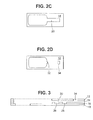
- Fig. 2A, Fig. 2B , Fig. 2C and Fig. 2D depict layers that may be stacked to form a test strip laminate.
- Fig. 3 shows a cross section of the stacked layers of Fig. 2A through Fig. 2D .
- Fig. 4A, Fig. 4B, and Fig. 4C depict a test strip according to the invention in a bending state proximate a blood sample to be tested, at different stages during the procedure of contacting the sample.
- Fig. 5A, Fig. 5B, Fig. 5C, and 5D depict the positioning of a fluid sample droplet on the test strip at different stages after a droplet of fluid sample is contacted with a test strip.
- Fig. 6 depicts an alternative embodiment of a test strip according to the invention.
- Fig. 7A, Fig. 7B, Fig. 7C, Fig. 7D, and Fig. 7E depict embodiments of the test strip according to the invention, where the depending portion has different shapes and configurations.
- the invention is a diagnostic test strip for testing a fluid sample, including for example, a blood sample obtained from a patient's body in a lancing operation.
- the strip has a first major side which is positioned facing a sample.
- a capillary channel having a mouth at one end and containing a measurement site toward the opposite end is positioned on the major side, such that fluid sample contacting the strip moves from the mouth through the capillary channel to the measurement site.
- the strip is provided with a fluid transport path which may be defined as having one end at the mouth of the capillary channel.
- a depending portion extends away from the strip on the side facing the fluid sample, such that a droplet of fluid sample contacting the depending portion is directed from the depending portion, along the fluid transport path, and to the mouth of the capillary channel
- the strip is provided with a lancet hole for passage of a lancet, and the fluid transport path extends from the side of the lancet hole adjacent the depending portion to the mouth of the capillary channel.
- the lancet passes through the hole to acquire blood from a patient, which is drawn with the lancet back through the lancet hole.
- the strip is arranged to a have a rolling bend in the portion of the strip that contacts the fluid sample, which causes a depending portion on the side of the lancet hole to extend in the direction of the fluid sample This may be accomplished using slits extending from the sides of the hole, for example,
- the reduced width of the depending portion causes the droplet to be guided toward the longitudinal centerline of the strip and toward the mouth of the capillary channel
- test strip 10 is shown with the major side facing up A top layer is removed to show the features of capillary channel 20.
- Fluid transport path 30 extends from the depending portion 50 to the mouth 21 of the capillary channel 20.
- trenches 80 on opposite sides of the fluid transport path 30 are recessed. Surface tension and adhesion of the sample fluid to the fluid transport path 30 prevent sample fluid from flowing into the trenches 80.
- the strip may be a multilayer laminate made up of layers as shown in Fig. 2A, Fig. 2B , Fig. 2C and Fig. 2D , stacked to obtain a cross-sectional configuration such as shown in Fig. 3 .
- Layers used to form a strip include layer 18 patterned with cutouts 22, 24 to form the depending portion 50; layer 16 defining reagent wells 26, 28 for electrochemical determination of blood glucose; layer 14, which defines the capillary channel walls, and top layer 12 ,which forms the top of the capillary channel including notch 32 at the mouth and vent 34 at the rear of the channel, which assist capillary flow of the sample.
- the design of the layers may be modified without departing from the scope of the invention.
- the construction of multilayer laminate test strips is described in U.S, Patent Nos. 7,192,405 and 7,498,132 , for example, incorporated herein by reference, and will not be further elaborated.
- lancet hole space 40 is provided for passage of a lancet.
- a fluid transport path 30 extends from the edge of lancet hole space 40 to the mouth of the capillary channel 20.
- the capillary channel 20 comprises wells 26, 28, containing reagents for performance of a diagnostic test, such as a blood glucose measurement using an electrochemical reaction.
- a diagnostic test such as a blood glucose measurement using an electrochemical reaction.
- any method of performing a diagnostic test may be used, and the invention is not limited to the use of electrochemical reagents to perform the diagnostic test.
- the fluid transport path 30 is preferably constructed of a hydrophobic material, so that a fluid sample should form a contact angle with the fluid transport path of greater than at least about 50 degrees, preferably greater than about 60 degrees and most preferably greater than about 70 degrees.
- Materials such as Mylar® having the appropriate characteristics can be used as laminate materials, Alternatively, treatments can be performed to render a different material for the fluid transport path more hydrophobic, including without limitation, silane or Rainex® coatings.
- the fluid transport path 30 is provided with a depending portion 50.
- the depending portion 50 preferentially contacts a droplet of fluid sample so that the droplet is directed to the center of the strip.
- the edges of the depending portion have reduced width d at the contact point which causes the droplet to be directed toward the center of the strip and toward the mouth of the capillary channel.
- the length of the fluid transport path 30 may vary from about 2 mm to about 6 mm.
- the path length should be larger than the blood droplet diameter to allow detection of the drop before filling the capillary. As the length of the path increases, the chance for sample loss also increases requiring a larger initial sample.
- the fluid transport path 30 is raised with respect to an area or areas adjacent the strip. It is believed that a droplet contacting a narrower raised portion initially will tend to stay on that path as the fluid progresses toward the capillary channel. The edge of the raised area creates a sharp change in direction of the surface that the sample is in contact with, and surface tension and contact angle keep it from falling off. While not limiting of the invention, in the preferred embodiment shown in Fig. 1 , recesses 80 adjacent the fluid transport path 30 extend on either side of the fluid transport path for substantially its entire length, from near the depending portion 50 to near the mouth of the capillary channel 20. Being narrower, the fluid transport path prevents loss of the sample along the strip.
- Fig. 4A, Fig. 4B and Fig. 4C depict a preferred embodiment in which a strip according to the invention is positioned proximate a fluid sample in a bending state, and moved so that a fluid sample (such as a blood droplet) is transported from the lancet hole space 40 on the fluid transport path 30 to the mouth of the capillary channel 20.
- the strip is moved in a rolling bend motion, in the direction shown by arrow.
- Fig. 4C represents a point in time shortly after Fig. 4B , which represents a point in time shortly after Fig. 4A .
- the bend in the strip causes the depending portion 50 to extend away from the strip toward the fluid sample.
- the depending portion extends at least about 100 :m to contact the fluid sample, measured as a distance on a line perpendicular to a line tangent to the bend of the strip to the most extended point on the depending portion away from the surface of the strip.
- Fig. 5A, Fig. 5B, Fig. 5C, and 5D which are arranged in a similar time-elapsed format, show how the droplet is centered on the strip and travels to the capillary channel.
- a droplet is shown oriented on one side of the strip as the depending portion contacts the strip.
- the droplet is directed along the curved edge of the depending portion 50 toward the center of the strip.
- Fig. 5C shows the droplet moments later, centered and directed toward the mouth of the capillary channel
- the depending portion 50 is formed at the side of the lancet hole space.
- Slits 70 are cut into the strip, as shown in Figs. 7A, 7B, 7C, 7D, and 7E so that depending portion is able to extend away at least about 100 :m from the plane of the strip when the strip bends, and preferably about 250 :m, or more.
- the curve or angle of the edge of the depending portion 50 guides the droplet toward the centerline of the strip where the mouth of the capillary channel is located.
- the slits 70 may have a length of about 1 mum to about 2 mm,
- the shape of slits 70 is not particularly limited, and the depending portion 50 may have a V shape, a U shape or any other convenient shape.
- the shape of the depending portion narrow in the direction of the droplet.
- the slits 70 may form a crescent shape in some embodiments and a triangle in other embodiments.
- the curved slits in this embodiment are believed to assist in directing the droplet toward the center of the strip.
- the depending portion may be placed on a strip as shown in Fig. 6 .
- depending portion 52 extends from the side of an individual strip and contacts and guides the droplet to the capillary channel in a similar fashion to the previously described embodiments, in that initial contact of the blood sample is with a narrow part of the depending portion.
- the channel 20 is on the side of the strip.
- test strips according to the invention may be embodied as several strip "units" on a continuous strip, so that a plurality of test sites can be located on a single strip and multiple test capability may be provided in a single device. Alternatively, single strips may be provided.
Abstract
Description
- The invention is in the field of fluid sample acquisition and tasting. In particular, the invention is directed to a test strip having features that facilitate transport of a blood sample obtained from a person's body to a measurement site on the strip.
- In the medical and diagnostic field, and particularly in the field of diabetes care, it is often desirable to perform testing on a fluid sample, such as a blood sample, collected on a test strip. The trend is to collect and test smaller fluid samples, including sub-microliter samples (i.e., samples having a volume of 1 :L or less). In this context, it is desirable to be able to direct a fluid sample collected on a test strip to a measurement site on the strip, and to ensure that enough of the sample is available to perform the required testing of the sample.
- It would be desirable in this context to have means to direct the fluid sample to the measurement site, ensuring sufficient sample to perform a measurement, without requiring involvement by the user.
- In application No.
12/502,494 -
Fig. 1 depicts a test strip according to the invention. -
Fig. 2A, Fig. 2B ,Fig. 2C and Fig. 2D depict layers that may be stacked to form a test strip laminate. -
Fig. 3 shows a cross section of the stacked layers ofFig. 2A through Fig. 2D . -
Fig. 4A, Fig. 4B, and Fig. 4C depict a test strip according to the invention in a bending state proximate a blood sample to be tested, at different stages during the procedure of contacting the sample. -
Fig. 5A, Fig. 5B, Fig. 5C, and 5D depict the positioning of a fluid sample droplet on the test strip at different stages after a droplet of fluid sample is contacted with a test strip. -
Fig. 6 depicts an alternative embodiment of a test strip according to the invention. -
Fig. 7A, Fig. 7B, Fig. 7C, Fig. 7D, and Fig. 7E depict embodiments of the test strip according to the invention, where the depending portion has different shapes and configurations. - In one aspect, the invention is a diagnostic test strip for testing a fluid sample, including for example, a blood sample obtained from a patient's body in a lancing operation. The strip has a first major side which is positioned facing a sample. A capillary channel having a mouth at one end and containing a measurement site toward the opposite end is positioned on the major side, such that fluid sample contacting the strip moves from the mouth through the capillary channel to the measurement site. The strip is provided with a fluid transport path which may be defined as having one end at the mouth of the capillary channel. A depending portion extends away from the strip on the side facing the fluid sample, such that a droplet of fluid sample contacting the depending portion is directed from the depending portion, along the fluid transport path, and to the mouth of the capillary channel
- In a preferred embodiment, the strip is provided with a lancet hole for passage of a lancet, and the fluid transport path extends from the side of the lancet hole adjacent the depending portion to the mouth of the capillary channel. The lancet passes through the hole to acquire blood from a patient, which is drawn with the lancet back through the lancet hole. The strip is arranged to a have a rolling bend in the portion of the strip that contacts the fluid sample, which causes a depending portion on the side of the lancet hole to extend in the direction of the fluid sample This may be accomplished using slits extending from the sides of the hole, for example, The reduced width of the depending portion causes the droplet to be guided toward the longitudinal centerline of the strip and toward the mouth of the capillary channel
- Referring to
Fig. 1 ,test strip 10 is shown with the major side facing up A top layer is removed to show the features ofcapillary channel 20.Fluid transport path 30 extends from the dependingportion 50 to themouth 21 of thecapillary channel 20. hi the embodiment shown,trenches 80 on opposite sides of thefluid transport path 30 are recessed. Surface tension and adhesion of the sample fluid to thefluid transport path 30 prevent sample fluid from flowing into thetrenches 80. - The strip may be a multilayer laminate made up of layers as shown in
Fig. 2A, Fig. 2B ,Fig. 2C and Fig. 2D , stacked to obtain a cross-sectional configuration such as shown inFig. 3 . Layers used to form a strip includelayer 18 patterned withcutouts portion 50;layer 16 definingreagent wells layer 14, which defines the capillary channel walls, andtop layer 12,which forms the top of the capillarychannel including notch 32 at the mouth andvent 34 at the rear of the channel, which assist capillary flow of the sample. The design of the layers may be modified without departing from the scope of the invention. The construction of multilayer laminate test strips is described inU.S, Patent Nos. 7,192,405 and7,498,132 , for example, incorporated herein by reference, and will not be further elaborated. - In the embodiment depicted in these Figures,
lancet hole space 40, is provided for passage of a lancet. Afluid transport path 30 extends from the edge oflancet hole space 40 to the mouth of thecapillary channel 20. In the embodiment shown, thecapillary channel 20 compriseswells - The
fluid transport path 30 is preferably constructed of a hydrophobic material, so that a fluid sample should form a contact angle with the fluid transport path of greater than at least about 50 degrees, preferably greater than about 60 degrees and most preferably greater than about 70 degrees. Materials such as Mylar® having the appropriate characteristics can be used as laminate materials, Alternatively, treatments can be performed to render a different material for the fluid transport path more hydrophobic, including without limitation, silane or Rainex® coatings. - The
fluid transport path 30 is provided with a dependingportion 50. When the strip initially contacts the fluid sample to be tested, the dependingportion 50 preferentially contacts a droplet of fluid sample so that the droplet is directed to the center of the strip. The edges of the depending portion have reduced width d at the contact point which causes the droplet to be directed toward the center of the strip and toward the mouth of the capillary channel. - The length of the
fluid transport path 30 may vary from about 2 mm to about 6 mm. The path length should be larger than the blood droplet diameter to allow detection of the drop before filling the capillary. As the length of the path increases, the chance for sample loss also increases requiring a larger initial sample. - In preferred embodiment, the
fluid transport path 30 is raised with respect to an area or areas adjacent the strip. It is believed that a droplet contacting a narrower raised portion initially will tend to stay on that path as the fluid progresses toward the capillary channel. The edge of the raised area creates a sharp change in direction of the surface that the sample is in contact with, and surface tension and contact angle keep it from falling off. While not limiting of the invention, in the preferred embodiment shown inFig. 1 , recesses 80 adjacent thefluid transport path 30 extend on either side of the fluid transport path for substantially its entire length, from near the dependingportion 50 to near the mouth of thecapillary channel 20. Being narrower, the fluid transport path prevents loss of the sample along the strip. -
Fig. 4A, Fig. 4B and Fig. 4C depict a preferred embodiment in which a strip according to the invention is positioned proximate a fluid sample in a bending state, and moved so that a fluid sample (such as a blood droplet) is transported from thelancet hole space 40 on thefluid transport path 30 to the mouth of thecapillary channel 20. The strip is moved in a rolling bend motion, in the direction shown by arrow.Fig. 4C represents a point in time shortly afterFig. 4B , which represents a point in time shortly afterFig. 4A . The bend in the strip causes the dependingportion 50 to extend away from the strip toward the fluid sample. Preferably, the depending portion extends at least about 100 :m to contact the fluid sample, measured as a distance on a line perpendicular to a line tangent to the bend of the strip to the most extended point on the depending portion away from the surface of the strip. -
Fig. 5A, Fig. 5B, Fig. 5C, and 5D which are arranged in a similar time-elapsed format, show how the droplet is centered on the strip and travels to the capillary channel. InFig. 5A , a droplet is shown oriented on one side of the strip as the depending portion contacts the strip. InFig. 5B , as the leading edge of the depending portion advances in the direction of travel A, the droplet is directed along the curved edge of the dependingportion 50 toward the center of the strip.Fig. 5C shows the droplet moments later, centered and directed toward the mouth of the capillary channel, - In a preferred embodiment, the depending
portion 50 is formed at the side of the lancet hole space.Slits 70 are cut into the strip, as shown inFigs. 7A, 7B, 7C, 7D, and 7E so that depending portion is able to extend away at least about 100 :m from the plane of the strip when the strip bends, and preferably about 250 :m, or more. The curve or angle of the edge of the dependingportion 50 guides the droplet toward the centerline of the strip where the mouth of the capillary channel is located. Theslits 70 may have a length of about 1 mum to about 2 mm, The shape ofslits 70 is not particularly limited, and the dependingportion 50 may have a V shape, a U shape or any other convenient shape. Generally, it is preferred to have the shape of the depending portion narrow in the direction of the droplet. Thus, theslits 70 may form a crescent shape in some embodiments and a triangle in other embodiments. The curved slits in this embodiment are believed to assist in directing the droplet toward the center of the strip. - In an alternative embodiment, the depending portion may be placed on a strip as shown in
Fig. 6 . InFig. 6 , dependingportion 52 extends from the side of an individual strip and contacts and guides the droplet to the capillary channel in a similar fashion to the previously described embodiments, in that initial contact of the blood sample is with a narrow part of the depending portion. In this embodiment, thechannel 20 is on the side of the strip. - Without departing from the scope of the invention, test strips according to the invention may be embodied as several strip "units" on a continuous strip, so that a plurality of test sites can be located on a single strip and multiple test capability may be provided in a single device. Alternatively, single strips may be provided.
- The foregoing description of the preferred embodiments is not to be deemed limiting of the invention, which is defined in the following claims.
Claims (13)
- A test strip for testing a fluid sample, comprising:a strip with a first major side for positioning facing a fluid sample;a capillary channel having a mouth and having a measurement site;a fluid transport path on the strip terminating at the mouth of the capillary channel;a depending portion at an end of the fluid transport path opposite the mouth of the capillary channel extending away from the strip whereby a droplet of fluid sample contacting the depending portion is directed to the mouth of the capillary channel.
- The test strip according to claim 1, further comprising
a lancet hole through the strip for passage of a lancet,
wherein the fluid transport path extends from the lancet hole to the mouth of the capillary channel, wherein the lancet hole preferably has a widest dimension of about 1 mm to about 2 mm, - The test strip according to claim 2, wherein the depending portion is formed by two slits in the strip extending from the lancet hole in a direction toward the capillary, forming a depending portion having a crescent shape, wherein the two slits preferably have an approximately equal length of greater than about 1 mm forming the depending portion at the side of the lancet hole.
- The test strip according to claim 2, wherein the strip is bent, causing the depending portion to extend away from the first major surface of the test strip by at least about 100 :m.
- The test strip according to claim 2, comprising a plurality of measurement sites on a continuous strip, each of said plurality of measurement sites associated with a lancet hole and a fluid transport path in the same manner, arranged for multiple tests to be conducted sequentially on the test strip.
- The test strip according to claim 5, wherein a portion of the continuous strip is in a bent state, and the portion of the strip in the bent state moves along the strip during use in a direction opposite to the direction of fluid sample on the strip.
- The test strip according to claim 1, wherein the measurement site comprises wells containing reagent for an electrochemical detection of glucose in a blood sample.
- The test strip according to claim 1, wherein a surface of the capillary channel is hydrophilic and/or wherein a surface of the fluid transport channel is hydrophobic.
- The test strip according to claim 8, wherein the surface of the capillary channel has sufficient hydrophilicity so that a droplet of blood thereon forms a contact angle of less than about 50 degrees and/or wherein the surface of the fluid transport channel has sufficient hydrophobicity so that a droplet of blood thereon forms a contact angle of greater than about 50 degrees.
- The test strip according to claim 1, comprising a multilayer laminate including an electrode layer and a plurality of polymeric structural layers and/or wherein the volume of the capillary channel is less than about 1.0 :L.
- The test strip according to claim 1, further comprising recesses adjacent each lateral side of the fluid transport path, extending substantially the entire length of the fluid transport path, from near the depending portion to near the mouth of the capillary channel.
- A test strip for testing a fluid sample, comprising:a strip with a first major side for positioning facing a fluid sample;a capillary channel having a mouth and having a measurement site;a fluid transport path on the substrate having sides and an end at the mouth of the capillary channel;at least one recess adjacent a side of the fluid transport path, whereby a fluid sample contacting the fluid transport path is preferentially directed to the mouth of the capillary channel.
- The test strip according to claim 12, further comprising
a lancet hole through the substrate for passage of a lancet, wherein the fluid transport path extends from the lancet hole to the mouth of the capillary channel and/or
two recesses adjacent opposite sides of the fluid transport path, such that the fluid transport path is a raised path having a width narrower than the lancet hole at its widest point.
Applications Claiming Priority (1)
| Application Number | Priority Date | Filing Date | Title |
|---|---|---|---|
| US12/502,585 US8337422B2 (en) | 2009-07-14 | 2009-07-14 | Diagnostic test strip having fluid transport features |
Publications (2)
| Publication Number | Publication Date |
|---|---|
| EP2275820A1 true EP2275820A1 (en) | 2011-01-19 |
| EP2275820B1 EP2275820B1 (en) | 2016-12-07 |
Family
ID=42782079
Family Applications (1)
| Application Number | Title | Priority Date | Filing Date |
|---|---|---|---|
| EP10169279.6A Active EP2275820B1 (en) | 2009-07-14 | 2010-07-12 | Diagnostic test strip having fluid transport features |
Country Status (5)
| Country | Link |
|---|---|
| US (1) | US8337422B2 (en) |
| EP (1) | EP2275820B1 (en) |
| JP (1) | JP5771368B2 (en) |
| CA (1) | CA2709192C (en) |
| ES (1) | ES2616783T3 (en) |
Cited By (1)
| Publication number | Priority date | Publication date | Assignee | Title |
|---|---|---|---|---|
| CN102613978A (en) * | 2011-01-31 | 2012-08-01 | 厚美德生物科技股份有限公司 | Detection test piece |
Families Citing this family (13)
| Publication number | Priority date | Publication date | Assignee | Title |
|---|---|---|---|---|
| US8771202B2 (en) | 2010-01-19 | 2014-07-08 | Becton Dickinson And Company | Electrode layout for blood test sensor strip |
| TW201231964A (en) * | 2011-01-31 | 2012-08-01 | Hmd Biomedical Inc | Test strip |
| JP6274765B2 (en) * | 2012-12-25 | 2018-02-07 | 矢崎総業株式会社 | Wire harness |
| CN106574929B (en) * | 2014-07-25 | 2019-08-09 | 贝克顿·迪金森公司 | Analyte testing item test and for its implement test-strips and kit |
| US20190247851A1 (en) * | 2018-02-12 | 2019-08-15 | Athelas, Inc. | Capillary-loaded analysis device for biological fluid samples |
| CA3131245A1 (en) * | 2019-02-26 | 2020-09-03 | Truvian Sciences, Inc. | Assay device and method of use thereof |
| USD895141S1 (en) * | 2019-05-01 | 2020-09-01 | Testcard Ltd. | Medical test card |
| USD895140S1 (en) * | 2019-05-01 | 2020-09-01 | Testcard Ltd. | Medical test card |
| USD938607S1 (en) * | 2020-04-01 | 2021-12-14 | Sense Biodetection Limited | Diagnostic test device |
| USD954295S1 (en) | 2020-05-18 | 2022-06-07 | Truvian Sciences, Inc. | Disc |
| USD960386S1 (en) | 2020-05-18 | 2022-08-09 | Truvian Sciences, Inc. | Disc |
| USD970746S1 (en) * | 2020-06-25 | 2022-11-22 | Mitsubishi Paper Mills Limited | Stage for cell cryopreservation operation |
| USD959693S1 (en) | 2021-03-31 | 2022-08-02 | Sense Biodetection Limited | Diagnostic test device |
Citations (6)
| Publication number | Priority date | Publication date | Assignee | Title |
|---|---|---|---|---|
| WO2002095396A2 (en) * | 2001-05-18 | 2002-11-28 | Acon Laboratories, Inc. | In line test device and methods of use |
| WO2003087775A2 (en) * | 2002-04-05 | 2003-10-23 | Eyelab Group,Llc | Monitoring blood substances using self-sampled tears |
| US7192405B2 (en) | 2002-09-30 | 2007-03-20 | Becton, Dickinson And Company | Integrated lancet and bodily fluid sensor |
| US7498132B2 (en) | 2000-02-02 | 2009-03-03 | Lifescan, Inc. | Electrochemical test strip kit for analyte determination |
| US7524456B1 (en) * | 1992-05-21 | 2009-04-28 | Biosite Incorporated | Diagnostic devices for the controlled movement of reagents without membranes |
| WO2009125092A2 (en) * | 2008-03-31 | 2009-10-15 | Commissariat A L'energie Atomique | Device for aliquoting and filtering blood |
Family Cites Families (19)
| Publication number | Priority date | Publication date | Assignee | Title |
|---|---|---|---|---|
| FR2705150B1 (en) | 1993-05-10 | 1995-07-21 | Asulab Sa | Multiple zone electrochemical sensor on disk and its application to glucose measurement. |
| DE4427363A1 (en) | 1993-08-03 | 1995-03-09 | A & D Co Ltd | A disposable chemical sensor |
| US5437999A (en) | 1994-02-22 | 1995-08-01 | Boehringer Mannheim Corporation | Electrochemical sensor |
| JP3394262B2 (en) | 1997-02-06 | 2003-04-07 | セラセンス、インク. | Small volume in vitro analyte sensor |
| US6071391A (en) | 1997-09-12 | 2000-06-06 | Nok Corporation | Enzyme electrode structure |
| US6878345B1 (en) | 1997-12-08 | 2005-04-12 | Thomas W. Astle | Ultra high throughput bioassay screening system |
| US6558402B1 (en) | 1999-08-03 | 2003-05-06 | Becton, Dickinson And Company | Lancer |
| JP2005501591A (en) * | 2001-08-29 | 2005-01-20 | エフ ホフマン−ラ ロッシュ アクチェン ゲゼルシャフト | Exudation method and structure for use in sampling body fluid |
| US6881578B2 (en) | 2002-04-02 | 2005-04-19 | Lifescan, Inc. | Analyte concentration determination meters and methods of using the same |
| US7604775B2 (en) * | 2002-08-12 | 2009-10-20 | Bayer Healthcare Llc | Fluid collecting and monitoring device |
| US7731900B2 (en) | 2002-11-26 | 2010-06-08 | Roche Diagnostics Operations, Inc. | Body fluid testing device |
| US7223248B2 (en) * | 2003-08-13 | 2007-05-29 | Lifescan, Inc. | Packaged medical device with a deployable dermal tissue penetration member |
| JP4334969B2 (en) * | 2003-10-02 | 2009-09-30 | パナソニック株式会社 | Blood component analysis sensor |
| US7378270B2 (en) | 2003-11-10 | 2008-05-27 | Sentec Scientific, Inc. | Device for analyte measurement |
| US7909776B2 (en) * | 2004-04-30 | 2011-03-22 | Roche Diagnostics Operations, Inc. | Lancets for bodily fluid sampling supplied on a tape |
| US7955271B2 (en) * | 2006-10-13 | 2011-06-07 | Roche Diagnostics Operations, Inc. | Tape transport lance sampler |
| ATE528652T1 (en) | 2005-06-29 | 2011-10-15 | Hoffmann La Roche | ANALYSIS SYSTEM WITH TEST TAPE |
| US8337423B2 (en) * | 2009-07-14 | 2012-12-25 | Becton, Dickinson And Company | Blood glucose sensor |
| US8771202B2 (en) | 2010-01-19 | 2014-07-08 | Becton Dickinson And Company | Electrode layout for blood test sensor strip |
-
2009
- 2009-07-14 US US12/502,585 patent/US8337422B2/en active Active
-
2010
- 2010-07-08 CA CA2709192A patent/CA2709192C/en active Active
- 2010-07-12 EP EP10169279.6A patent/EP2275820B1/en active Active
- 2010-07-12 ES ES10169279.6T patent/ES2616783T3/en active Active
- 2010-07-14 JP JP2010159854A patent/JP5771368B2/en active Active
Patent Citations (6)
| Publication number | Priority date | Publication date | Assignee | Title |
|---|---|---|---|---|
| US7524456B1 (en) * | 1992-05-21 | 2009-04-28 | Biosite Incorporated | Diagnostic devices for the controlled movement of reagents without membranes |
| US7498132B2 (en) | 2000-02-02 | 2009-03-03 | Lifescan, Inc. | Electrochemical test strip kit for analyte determination |
| WO2002095396A2 (en) * | 2001-05-18 | 2002-11-28 | Acon Laboratories, Inc. | In line test device and methods of use |
| WO2003087775A2 (en) * | 2002-04-05 | 2003-10-23 | Eyelab Group,Llc | Monitoring blood substances using self-sampled tears |
| US7192405B2 (en) | 2002-09-30 | 2007-03-20 | Becton, Dickinson And Company | Integrated lancet and bodily fluid sensor |
| WO2009125092A2 (en) * | 2008-03-31 | 2009-10-15 | Commissariat A L'energie Atomique | Device for aliquoting and filtering blood |
Cited By (1)
| Publication number | Priority date | Publication date | Assignee | Title |
|---|---|---|---|---|
| CN102613978A (en) * | 2011-01-31 | 2012-08-01 | 厚美德生物科技股份有限公司 | Detection test piece |
Also Published As
| Publication number | Publication date |
|---|---|
| US20110015545A1 (en) | 2011-01-20 |
| EP2275820B1 (en) | 2016-12-07 |
| CA2709192A1 (en) | 2011-01-14 |
| JP5771368B2 (en) | 2015-08-26 |
| ES2616783T3 (en) | 2017-06-14 |
| CA2709192C (en) | 2019-09-10 |
| JP2011050734A (en) | 2011-03-17 |
| US8337422B2 (en) | 2012-12-25 |
Similar Documents
| Publication | Publication Date | Title |
|---|---|---|
| US8337422B2 (en) | Diagnostic test strip having fluid transport features | |
| JP5070210B2 (en) | Device that facilitates fluid transfer | |
| US7238534B1 (en) | Capillary active test element having an intermediate layer situated between the support and the covering | |
| US8000762B2 (en) | Body fluid sampling device | |
| US7305896B2 (en) | Capillary fill test device | |
| CN1951330B (en) | Integrated lance and strip for analysis measurement | |
| CN100393277C (en) | Integrated pricking pin and braid used for analyte measurement | |
| US20090099477A1 (en) | Lancet wheel | |
| CN101313851A (en) | Flexible lancet | |
| JP2009517104A (en) | Bent lancet | |
| JP2011050734A5 (en) | ||
| US20070197937A1 (en) | Microfluid system and method for production thereof | |
| JP2004298629A (en) | Measuring method of analyte using integrated lance and strip | |
| US20070299365A1 (en) | Sampling system for sample fluid | |
| EP2402759A1 (en) | Testing strip for detecting a fluidic sample | |
| JP2013530409A (en) | Test strip for body fluid sample detection | |
| JP4796598B2 (en) | Puncture wound formation system | |
| US20090093735A1 (en) | Test unit and test system for analyzing body fluids | |
| US8333713B2 (en) | Lancet comprising a test region | |
| JP2008167942A (en) | Biosensor cartridge | |
| MXPA00005419A (en) | Capillary active test element having an intermediate layer situated between the support and the covering |
Legal Events
| Date | Code | Title | Description |
|---|---|---|---|
| PUAI | Public reference made under article 153(3) epc to a published international application that has entered the european phase |
Free format text: ORIGINAL CODE: 0009012 |
|
| AK | Designated contracting states |
Kind code of ref document: A1 Designated state(s): AL AT BE BG CH CY CZ DE DK EE ES FI FR GB GR HR HU IE IS IT LI LT LU LV MC MK MT NL NO PL PT RO SE SI SK SM TR |
|
| AX | Request for extension of the european patent |
Extension state: BA ME RS |
|
| 17P | Request for examination filed |
Effective date: 20110701 |
|
| 17Q | First examination report despatched |
Effective date: 20121204 |
|
| REG | Reference to a national code |
Ref country code: DE Ref legal event code: R079 Ref document number: 602010038575 Country of ref document: DE Free format text: PREVIOUS MAIN CLASS: G01N0033660000 Ipc: B01L0003000000 |
|
| GRAP | Despatch of communication of intention to grant a patent |
Free format text: ORIGINAL CODE: EPIDOSNIGR1 |
|
| RIC1 | Information provided on ipc code assigned before grant |
Ipc: G01N 33/559 20060101ALI20160429BHEP Ipc: G01N 27/327 20060101ALI20160429BHEP Ipc: B01L 3/00 20060101AFI20160429BHEP |
|
| INTG | Intention to grant announced |
Effective date: 20160602 |
|
| GRAS | Grant fee paid |
Free format text: ORIGINAL CODE: EPIDOSNIGR3 |
|
| GRAA | (expected) grant |
Free format text: ORIGINAL CODE: 0009210 |
|
| AK | Designated contracting states |
Kind code of ref document: B1 Designated state(s): AL AT BE BG CH CY CZ DE DK EE ES FI FR GB GR HR HU IE IS IT LI LT LU LV MC MK MT NL NO PL PT RO SE SI SK SM TR |
|
| RAP1 | Party data changed (applicant data changed or rights of an application transferred) |
Owner name: BECTON, DICKINSON AND COMPANY |
|
| REG | Reference to a national code |
Ref country code: GB Ref legal event code: FG4D |
|
| REG | Reference to a national code |
Ref country code: CH Ref legal event code: EP Ref country code: AT Ref legal event code: REF Ref document number: 851261 Country of ref document: AT Kind code of ref document: T Effective date: 20161215 |
|
| REG | Reference to a national code |
Ref country code: IE Ref legal event code: FG4D |
|
| REG | Reference to a national code |
Ref country code: DE Ref legal event code: R096 Ref document number: 602010038575 Country of ref document: DE |
|
| PG25 | Lapsed in a contracting state [announced via postgrant information from national office to epo] |
Ref country code: LV Free format text: LAPSE BECAUSE OF FAILURE TO SUBMIT A TRANSLATION OF THE DESCRIPTION OR TO PAY THE FEE WITHIN THE PRESCRIBED TIME-LIMIT Effective date: 20161207 |
|
| REG | Reference to a national code |
Ref country code: LT Ref legal event code: MG4D |
|
| REG | Reference to a national code |
Ref country code: NL Ref legal event code: MP Effective date: 20161207 |
|
| PG25 | Lapsed in a contracting state [announced via postgrant information from national office to epo] |
Ref country code: NO Free format text: LAPSE BECAUSE OF FAILURE TO SUBMIT A TRANSLATION OF THE DESCRIPTION OR TO PAY THE FEE WITHIN THE PRESCRIBED TIME-LIMIT Effective date: 20170307 Ref country code: GR Free format text: LAPSE BECAUSE OF FAILURE TO SUBMIT A TRANSLATION OF THE DESCRIPTION OR TO PAY THE FEE WITHIN THE PRESCRIBED TIME-LIMIT Effective date: 20170308 Ref country code: SE Free format text: LAPSE BECAUSE OF FAILURE TO SUBMIT A TRANSLATION OF THE DESCRIPTION OR TO PAY THE FEE WITHIN THE PRESCRIBED TIME-LIMIT Effective date: 20161207 Ref country code: LT Free format text: LAPSE BECAUSE OF FAILURE TO SUBMIT A TRANSLATION OF THE DESCRIPTION OR TO PAY THE FEE WITHIN THE PRESCRIBED TIME-LIMIT Effective date: 20161207 |
|
| REG | Reference to a national code |
Ref country code: AT Ref legal event code: MK05 Ref document number: 851261 Country of ref document: AT Kind code of ref document: T Effective date: 20161207 |
|
| PG25 | Lapsed in a contracting state [announced via postgrant information from national office to epo] |
Ref country code: FI Free format text: LAPSE BECAUSE OF FAILURE TO SUBMIT A TRANSLATION OF THE DESCRIPTION OR TO PAY THE FEE WITHIN THE PRESCRIBED TIME-LIMIT Effective date: 20161207 Ref country code: HR Free format text: LAPSE BECAUSE OF FAILURE TO SUBMIT A TRANSLATION OF THE DESCRIPTION OR TO PAY THE FEE WITHIN THE PRESCRIBED TIME-LIMIT Effective date: 20161207 |
|
| REG | Reference to a national code |
Ref country code: ES Ref legal event code: FG2A Ref document number: 2616783 Country of ref document: ES Kind code of ref document: T3 Effective date: 20170614 |
|
| REG | Reference to a national code |
Ref country code: FR Ref legal event code: PLFP Year of fee payment: 8 |
|
| PG25 | Lapsed in a contracting state [announced via postgrant information from national office to epo] |
Ref country code: NL Free format text: LAPSE BECAUSE OF FAILURE TO SUBMIT A TRANSLATION OF THE DESCRIPTION OR TO PAY THE FEE WITHIN THE PRESCRIBED TIME-LIMIT Effective date: 20161207 |
|
| PG25 | Lapsed in a contracting state [announced via postgrant information from national office to epo] |
Ref country code: CZ Free format text: LAPSE BECAUSE OF FAILURE TO SUBMIT A TRANSLATION OF THE DESCRIPTION OR TO PAY THE FEE WITHIN THE PRESCRIBED TIME-LIMIT Effective date: 20161207 Ref country code: SK Free format text: LAPSE BECAUSE OF FAILURE TO SUBMIT A TRANSLATION OF THE DESCRIPTION OR TO PAY THE FEE WITHIN THE PRESCRIBED TIME-LIMIT Effective date: 20161207 Ref country code: IS Free format text: LAPSE BECAUSE OF FAILURE TO SUBMIT A TRANSLATION OF THE DESCRIPTION OR TO PAY THE FEE WITHIN THE PRESCRIBED TIME-LIMIT Effective date: 20170407 Ref country code: EE Free format text: LAPSE BECAUSE OF FAILURE TO SUBMIT A TRANSLATION OF THE DESCRIPTION OR TO PAY THE FEE WITHIN THE PRESCRIBED TIME-LIMIT Effective date: 20161207 Ref country code: RO Free format text: LAPSE BECAUSE OF FAILURE TO SUBMIT A TRANSLATION OF THE DESCRIPTION OR TO PAY THE FEE WITHIN THE PRESCRIBED TIME-LIMIT Effective date: 20161207 |
|
| PG25 | Lapsed in a contracting state [announced via postgrant information from national office to epo] |
Ref country code: SM Free format text: LAPSE BECAUSE OF FAILURE TO SUBMIT A TRANSLATION OF THE DESCRIPTION OR TO PAY THE FEE WITHIN THE PRESCRIBED TIME-LIMIT Effective date: 20161207 Ref country code: BG Free format text: LAPSE BECAUSE OF FAILURE TO SUBMIT A TRANSLATION OF THE DESCRIPTION OR TO PAY THE FEE WITHIN THE PRESCRIBED TIME-LIMIT Effective date: 20170307 Ref country code: BE Free format text: LAPSE BECAUSE OF FAILURE TO SUBMIT A TRANSLATION OF THE DESCRIPTION OR TO PAY THE FEE WITHIN THE PRESCRIBED TIME-LIMIT Effective date: 20161207 Ref country code: PL Free format text: LAPSE BECAUSE OF FAILURE TO SUBMIT A TRANSLATION OF THE DESCRIPTION OR TO PAY THE FEE WITHIN THE PRESCRIBED TIME-LIMIT Effective date: 20161207 Ref country code: AT Free format text: LAPSE BECAUSE OF FAILURE TO SUBMIT A TRANSLATION OF THE DESCRIPTION OR TO PAY THE FEE WITHIN THE PRESCRIBED TIME-LIMIT Effective date: 20161207 Ref country code: PT Free format text: LAPSE BECAUSE OF FAILURE TO SUBMIT A TRANSLATION OF THE DESCRIPTION OR TO PAY THE FEE WITHIN THE PRESCRIBED TIME-LIMIT Effective date: 20170407 |
|
| REG | Reference to a national code |
Ref country code: DE Ref legal event code: R097 Ref document number: 602010038575 Country of ref document: DE |
|
| PLBE | No opposition filed within time limit |
Free format text: ORIGINAL CODE: 0009261 |
|
| STAA | Information on the status of an ep patent application or granted ep patent |
Free format text: STATUS: NO OPPOSITION FILED WITHIN TIME LIMIT |
|
| 26N | No opposition filed |
Effective date: 20170908 |
|
| PG25 | Lapsed in a contracting state [announced via postgrant information from national office to epo] |
Ref country code: SI Free format text: LAPSE BECAUSE OF FAILURE TO SUBMIT A TRANSLATION OF THE DESCRIPTION OR TO PAY THE FEE WITHIN THE PRESCRIBED TIME-LIMIT Effective date: 20161207 Ref country code: DK Free format text: LAPSE BECAUSE OF FAILURE TO SUBMIT A TRANSLATION OF THE DESCRIPTION OR TO PAY THE FEE WITHIN THE PRESCRIBED TIME-LIMIT Effective date: 20161207 |
|
| REG | Reference to a national code |
Ref country code: CH Ref legal event code: PL |
|
| REG | Reference to a national code |
Ref country code: IE Ref legal event code: MM4A |
|
| PG25 | Lapsed in a contracting state [announced via postgrant information from national office to epo] |
Ref country code: LI Free format text: LAPSE BECAUSE OF NON-PAYMENT OF DUE FEES Effective date: 20170731 Ref country code: CH Free format text: LAPSE BECAUSE OF NON-PAYMENT OF DUE FEES Effective date: 20170731 Ref country code: IE Free format text: LAPSE BECAUSE OF NON-PAYMENT OF DUE FEES Effective date: 20170712 |
|
| REG | Reference to a national code |
Ref country code: FR Ref legal event code: PLFP Year of fee payment: 9 |
|
| PG25 | Lapsed in a contracting state [announced via postgrant information from national office to epo] |
Ref country code: LU Free format text: LAPSE BECAUSE OF NON-PAYMENT OF DUE FEES Effective date: 20170712 |
|
| PG25 | Lapsed in a contracting state [announced via postgrant information from national office to epo] |
Ref country code: MT Free format text: LAPSE BECAUSE OF NON-PAYMENT OF DUE FEES Effective date: 20170712 |
|
| PG25 | Lapsed in a contracting state [announced via postgrant information from national office to epo] |
Ref country code: MC Free format text: LAPSE BECAUSE OF FAILURE TO SUBMIT A TRANSLATION OF THE DESCRIPTION OR TO PAY THE FEE WITHIN THE PRESCRIBED TIME-LIMIT Effective date: 20161207 Ref country code: HU Free format text: LAPSE BECAUSE OF FAILURE TO SUBMIT A TRANSLATION OF THE DESCRIPTION OR TO PAY THE FEE WITHIN THE PRESCRIBED TIME-LIMIT; INVALID AB INITIO Effective date: 20100712 |
|
| PG25 | Lapsed in a contracting state [announced via postgrant information from national office to epo] |
Ref country code: CY Free format text: LAPSE BECAUSE OF NON-PAYMENT OF DUE FEES Effective date: 20161207 |
|
| PG25 | Lapsed in a contracting state [announced via postgrant information from national office to epo] |
Ref country code: MK Free format text: LAPSE BECAUSE OF FAILURE TO SUBMIT A TRANSLATION OF THE DESCRIPTION OR TO PAY THE FEE WITHIN THE PRESCRIBED TIME-LIMIT Effective date: 20161207 |
|
| PG25 | Lapsed in a contracting state [announced via postgrant information from national office to epo] |
Ref country code: TR Free format text: LAPSE BECAUSE OF FAILURE TO SUBMIT A TRANSLATION OF THE DESCRIPTION OR TO PAY THE FEE WITHIN THE PRESCRIBED TIME-LIMIT Effective date: 20161207 |
|
| PG25 | Lapsed in a contracting state [announced via postgrant information from national office to epo] |
Ref country code: AL Free format text: LAPSE BECAUSE OF FAILURE TO SUBMIT A TRANSLATION OF THE DESCRIPTION OR TO PAY THE FEE WITHIN THE PRESCRIBED TIME-LIMIT Effective date: 20161207 |
|
| PGFP | Annual fee paid to national office [announced via postgrant information from national office to epo] |
Ref country code: IT Payment date: 20221122 Year of fee payment: 13 Ref country code: GB Payment date: 20221108 Year of fee payment: 13 Ref country code: FR Payment date: 20221109 Year of fee payment: 13 Ref country code: ES Payment date: 20221114 Year of fee payment: 13 Ref country code: DE Payment date: 20221108 Year of fee payment: 13 |
|
| P01 | Opt-out of the competence of the unified patent court (upc) registered |
Effective date: 20230427 |
|
| REG | Reference to a national code |
Ref country code: DE Ref legal event code: R119 Ref document number: 602010038575 Country of ref document: DE |
|
| GBPC | Gb: european patent ceased through non-payment of renewal fee |
Effective date: 20230712 |