EP2273777A2 - Method of controlling an image capturing system - Google Patents
Method of controlling an image capturing system Download PDFInfo
- Publication number
- EP2273777A2 EP2273777A2 EP10183718A EP10183718A EP2273777A2 EP 2273777 A2 EP2273777 A2 EP 2273777A2 EP 10183718 A EP10183718 A EP 10183718A EP 10183718 A EP10183718 A EP 10183718A EP 2273777 A2 EP2273777 A2 EP 2273777A2
- Authority
- EP
- European Patent Office
- Prior art keywords
- array
- intensity values
- image
- intensity
- arrays
- Prior art date
- Legal status (The legal status is an assumption and is not a legal conclusion. Google has not performed a legal analysis and makes no representation as to the accuracy of the status listed.)
- Withdrawn
Links
- 238000000034 method Methods 0.000 title claims abstract description 44
- 238000003491 array Methods 0.000 claims abstract description 72
- 238000012545 processing Methods 0.000 claims description 26
- 230000006835 compression Effects 0.000 claims description 10
- 238000007906 compression Methods 0.000 claims description 10
- 230000009466 transformation Effects 0.000 claims description 6
- 230000001131 transforming effect Effects 0.000 claims description 2
- 230000008901 benefit Effects 0.000 description 8
- 238000007792 addition Methods 0.000 description 6
- 230000000694 effects Effects 0.000 description 6
- 230000035945 sensitivity Effects 0.000 description 6
- 238000003860 storage Methods 0.000 description 6
- 230000001965 increasing effect Effects 0.000 description 5
- 230000003247 decreasing effect Effects 0.000 description 4
- 230000006870 function Effects 0.000 description 4
- 230000004044 response Effects 0.000 description 4
- 230000003321 amplification Effects 0.000 description 2
- 230000015572 biosynthetic process Effects 0.000 description 2
- 230000000295 complement effect Effects 0.000 description 2
- 238000004590 computer program Methods 0.000 description 2
- 230000007423 decrease Effects 0.000 description 2
- 238000005516 engineering process Methods 0.000 description 2
- 230000002708 enhancing effect Effects 0.000 description 2
- 229910044991 metal oxide Inorganic materials 0.000 description 2
- 150000004706 metal oxides Chemical class 0.000 description 2
- 238000003199 nucleic acid amplification method Methods 0.000 description 2
- 239000004065 semiconductor Substances 0.000 description 2
- 238000007493 shaping process Methods 0.000 description 2
- 238000012935 Averaging Methods 0.000 description 1
- 208000033748 Device issues Diseases 0.000 description 1
- 241001465754 Metazoa Species 0.000 description 1
- 206010044565 Tremor Diseases 0.000 description 1
- 238000009825 accumulation Methods 0.000 description 1
- 230000009286 beneficial effect Effects 0.000 description 1
- 239000003990 capacitor Substances 0.000 description 1
- 230000008859 change Effects 0.000 description 1
- 238000006243 chemical reaction Methods 0.000 description 1
- 230000001447 compensatory effect Effects 0.000 description 1
- 238000010586 diagram Methods 0.000 description 1
- 238000009826 distribution Methods 0.000 description 1
- 238000001914 filtration Methods 0.000 description 1
- 230000004907 flux Effects 0.000 description 1
- 239000004973 liquid crystal related substance Substances 0.000 description 1
- 238000004519 manufacturing process Methods 0.000 description 1
- 238000002156 mixing Methods 0.000 description 1
- 230000003287 optical effect Effects 0.000 description 1
- 238000005192 partition Methods 0.000 description 1
- 230000008569 process Effects 0.000 description 1
- 230000009467 reduction Effects 0.000 description 1
- 238000013341 scale-up Methods 0.000 description 1
- 238000012549 training Methods 0.000 description 1
- 238000012546 transfer Methods 0.000 description 1
Images

Classifications
-
- H—ELECTRICITY
- H04—ELECTRIC COMMUNICATION TECHNIQUE
- H04N—PICTORIAL COMMUNICATION, e.g. TELEVISION
- H04N23/00—Cameras or camera modules comprising electronic image sensors; Control thereof
- H04N23/95—Computational photography systems, e.g. light-field imaging systems
- H04N23/951—Computational photography systems, e.g. light-field imaging systems by using two or more images to influence resolution, frame rate or aspect ratio
-
- H—ELECTRICITY
- H04—ELECTRIC COMMUNICATION TECHNIQUE
- H04N—PICTORIAL COMMUNICATION, e.g. TELEVISION
- H04N23/00—Cameras or camera modules comprising electronic image sensors; Control thereof
- H04N23/70—Circuitry for compensating brightness variation in the scene
- H04N23/72—Combination of two or more compensation controls
-
- H—ELECTRICITY
- H04—ELECTRIC COMMUNICATION TECHNIQUE
- H04N—PICTORIAL COMMUNICATION, e.g. TELEVISION
- H04N25/00—Circuitry of solid-state image sensors [SSIS]; Control thereof
- H04N25/40—Extracting pixel data from image sensors by controlling scanning circuits, e.g. by modifying the number of pixels sampled or to be sampled
- H04N25/42—Extracting pixel data from image sensors by controlling scanning circuits, e.g. by modifying the number of pixels sampled or to be sampled by switching between different modes of operation using different resolutions or aspect ratios, e.g. switching between interlaced and non-interlaced mode
-
- H—ELECTRICITY
- H04—ELECTRIC COMMUNICATION TECHNIQUE
- H04N—PICTORIAL COMMUNICATION, e.g. TELEVISION
- H04N25/00—Circuitry of solid-state image sensors [SSIS]; Control thereof
- H04N25/40—Extracting pixel data from image sensors by controlling scanning circuits, e.g. by modifying the number of pixels sampled or to be sampled
- H04N25/44—Extracting pixel data from image sensors by controlling scanning circuits, e.g. by modifying the number of pixels sampled or to be sampled by partially reading an SSIS array
- H04N25/443—Extracting pixel data from image sensors by controlling scanning circuits, e.g. by modifying the number of pixels sampled or to be sampled by partially reading an SSIS array by reading pixels from selected 2D regions of the array, e.g. for windowing or digital zooming
-
- H—ELECTRICITY
- H04—ELECTRIC COMMUNICATION TECHNIQUE
- H04N—PICTORIAL COMMUNICATION, e.g. TELEVISION
- H04N25/00—Circuitry of solid-state image sensors [SSIS]; Control thereof
- H04N25/40—Extracting pixel data from image sensors by controlling scanning circuits, e.g. by modifying the number of pixels sampled or to be sampled
- H04N25/46—Extracting pixel data from image sensors by controlling scanning circuits, e.g. by modifying the number of pixels sampled or to be sampled by combining or binning pixels
-
- H—ELECTRICITY
- H04—ELECTRIC COMMUNICATION TECHNIQUE
- H04N—PICTORIAL COMMUNICATION, e.g. TELEVISION
- H04N3/00—Scanning details of television systems; Combination thereof with generation of supply voltages
- H04N3/10—Scanning details of television systems; Combination thereof with generation of supply voltages by means not exclusively optical-mechanical
- H04N3/14—Scanning details of television systems; Combination thereof with generation of supply voltages by means not exclusively optical-mechanical by means of electrically scanned solid-state devices
- H04N3/15—Scanning details of television systems; Combination thereof with generation of supply voltages by means not exclusively optical-mechanical by means of electrically scanned solid-state devices for picture signal generation
- H04N3/155—Control of the image-sensor operation, e.g. image processing within the image-sensor
- H04N3/1562—Control of the image-sensor operation, e.g. image processing within the image-sensor for selective scanning, e.g. windowing, zooming
Abstract
Description
- The invention relates to a method of controlling an image capturing system comprising an interface for receiving an external trigger to capture an image, and an image capturing device provided with a photosensitive area and an array of pixel cells, each pixel cell including a device for generating a signal indicative of the intensity of light falling on an associated part of the photosensitive area, which image capturing device is further provided with readout circuitry for generating an array of pixel values to capture an image frame at a set spatial resolution, such that each pixel value represents an integral of the signal or signals generated in at least one of the pixel cells in an associated one of a number of areas over an exposure time interval, the number of areas being determined by the set spatial resolution, the areas together covering a region of the photosensitive area corresponding to a region in the image.
- There are some aspects of the present invention that can be found in previously filed patent documents. For example,
US 2005/013509 andEP-A-0 358 498 disclose the ability to shorten the image capture time by mixing high and low resolution images.EP-A-0 358 498 also discloses to some extent the ability to keep image processing times short by using low complexity algorithms. -
EP-A-0 940 978 discloses the idea that a camera can capture a series of frames in response to a single external trigger. -
US-B1-6 590 198 discloses an analog video bus architecture that utilizes the column parallel nature of CMOS imagers and more specifically Active Column Sensors, that eliminates the need for multi-port imagers, by increasing the useable bandwidth of single port imagers. This allows for either binning or interpolation of pixel information for increased or decreased resolution along the columns and more specifically for ACS imagers binning or interpolation along the rows. -
WO 03/084207 - Furthermore,
EP-A-0 358 498 describes a method for enhancing the low resolution images in a sequence of mixed high and low resolution images by spatially interpolating the low resolution images and temporally interpolating between adjacent high resolution images, with the final result being a series of high resolution images. The method described inEP-A-0 358 498 is for enhancing a high resolution image which is under-exposed by using additional low-resolution images, which are also under-exposed in order to create a single final image which is both sharp and correctly exposed. - On the other hand, the present invention relates to a method whereby a sequence of images, one of high resolution and others of low resolution, are simply added together (after the low-resolution images are spatially interpolated) to create a final image with a resolution equivalent to the high resolution source image. The summing of the intensity values of images in the sequence is a real addition, because each under-exposed image in the sequence contains only a portion of the total desired intensity, so adding them together directly results in a final image of the desired intensity.
- The advantage described in
EP-A-0 940 978 and also inUS-A-5 657 402 is the ability to produce a high resolution wide angle final image using a series of images of differing focal lengths. Conversely, the advantage of the present invention is the ability to produce a sharp final image in low light conditions using a series of under-exposed images of differing resolutions - The invention also relates to an image capturing system. The invention also relates to a method of forming a combined final image from a plurality of image frames, including the steps of:
- obtaining a first and at least one further array of intensity values,
- each array of intensity values encoding light intensity levels at each of a respective number of pixel positions in the respective image frame, the number determining the spatial resolution of the image frame concerned,
- generating a set of derived arrays of intensity values, each derived array being based on a respective one of the obtained arrays of intensity levels and encoding light intensity levels at each of a common number of pixel positions in at least a region of overlap of the respective image frames, generating an array of combined intensity values, each element in the array based on a sum of intensity values represented by the corresponding element in each of the respective derived arrays of intensity values, and
- providing an array of intensity values encoding the combined final image, the array being based on the array of combined intensity values.
- The invention also relates to an image processing system.
- The invention also relates to a digital camera.
- The invention also relates to a computer program.
- International patent application
PCT/EP04/051080 WO 2006/119802 after the date of filing of the present application. It is thus comprised in the state of the art under Art. 54(3) EPC. - The aforementioned application describes a digital camera. The camera can be used in a substantially stationary position to capture a sequence of images and to derive a sequence of corresponding frames of pixel values representing the images. Each image is underexposed on purpose. The images are adjusted prior to forming them into a combined final image. The combined final image is formed by summing the values of corresponding pixels in the adjusted images. The combined final image may therefore be formed from underexposed images, but is itself sufficiently bright, as well as having good spatial resolution. The adjustment is used to prevent the combined final image from being blurred.
- A problem associated with capturing a series of underexposed image frames for later combination is due to the- types of image capturing devices available for use. Generally, these either have pixel cells comprising Charge Coupled Devices (CCDs) or are made with Complementary Metal Oxide Semiconductor (CMOS) sensors, in both cases with associated read-out circuitry. In particular when CCD arrays are used, the readout time, i.e. the time needed by the read-out circuitry to generate the array of pixel values encoding a frame, is very long. The time needed to capture a series of consecutive image frames for subsequent formation of a combined image, is thus even longer. Setting the image spatial resolution to a lower value results in a lower spatial resolution combined image if interpolation techniques are used to increase the spatial resolution of the captured image frames. Reducing the number of captured image frames on which to base the combined final image would achieve a lower total image capture time, but at the expense of a decreased signal-to-noise ratio (SNR) of the combined final image.
- It is an object of the invention to provide methods and systems of the type defined above, that results in image frames for formation into a combined final image with a relatively low noise level whilst requiring a relatively short overall image capture time.
- This object is achieved by means of the method according to the invention, which method comprises
receiving an external trigger to capture an image, and, in response to the external trigger, directing the image capturing device to capture at least two image frames by generating respective arrays of pixel values representing integrals over respective consecutive exposure time intervals,
wherein the spatial resolutions of at least two of the captured image frames are set to different values. - Because at least two of the captured image frames have different spatial resolutions, there is always at least one image frame with a higher and at least one with a lower resolution. Capturing an image frame with a higher resolution ensures that information with a high spatial frequency is present in the combined final image. Because not all image frames have the same, higher, resolution, the total time needed to capture and read out all the image data is relatively low, how- ever. Because the external trigger, e.g. a user command, results directly in the capture of at least two image frames, the image frames in the series follow each other as closely as possible, saving additional time. The change in settings to set a different resolution is also accomplished automatically in response to the external trigger. Because the image frames are captured separately in such a manner that they may be combined into a combined final image by summation, the combined final image may be composed of image frames with relatively short exposure times, leading to a combined final image with little blur.
- In a preferred embodiment, at least the lower of the spatial resolution values is set by directing the image capturing device to generate an array of pixel values in such a manner that each pixel value is representative of the integral of the sum of the signals generated by at least two devices in pixel cells.
- Such a technique is commonly referred to as "inning" and has the effect of increasing sensitivity, because the two or more devices in pixel cells effectively occupy a larger part of the photosensitive area. Furthermore, the captured image frame has a lower noise level.
- A preferred embodiment includes retrieving a desired exposure time for a combined final image, determining the number of image frames to be captured, and for each image frame, calculating settings determining an exposure level applicable to the image frame, the settings including the length of the exposure time interval, wherein the settings are calculated so that the sum of the lengths of the exposure time intervals over the number of image frames is equal to or less than the desired exposure time.
- Each of the captured images is underexposed when viewed alone. The combined final image is not, however, because it is based on the combined total of image frames. This embodiment has the advantage that it enables addition of intensity levels representative of pixel values in the various image frames to generate one combined final image with a correct exposure.
- An embodiment includes the step of generating a set of arrays of pixel values, each based on one of the captured image frames, in such a manner that each encodes at least a region of an adjusted frame at the same spatial resolution.
- This embodiment increases the suitability of the captured image frames for generating a combined final image by summing corresponding pixel values in at least the regions of the adjusted frames.
- According to another aspect of the invention, there is provided an image capturing system comprising
an interface for receiving an external trigger to capture an image,
an image capturing device provided with a photosensitive area and an array of pixel cells, each pixel cell including a device for generating a signal indicative of the intensity of light falling on an associated part of the photosensitive area, which image capturing device is further provided with readout circuitry for generating an array of pixel values to capture an image frame at a set spatial resolution, such that each pixel value represents an integral of the signal or signals generated in at least one of the pixel cells in an associated one of a number of areas over an exposure time interval, the number of areas being determined by the set spatial resolution, the areas together covering a region of the photosensitive area corresponding to a region in the image, which image capturing system comprises
a control system for controlling the operation of the image capturing device and for processing commands received through the interface,
wherein the control system is configured to, in response to the external trigger, direct the image capturing device to capture at least two image frames by generating respective arrays of pixel values representing integrals over respective consecutive exposure time intervals,
wherein the control system is further configured to set the spatial resolutions of at least two of the captured image frames to different values. - In a preferred embodiment, the image capturing system according to the invention is configured to execute a method of capturing an image according to the invention.
- According to another aspect of the invention, the method of forming a combined final image from a plurality of image frames includes the steps of: obtaining a first and at least one further array of intensity values,
each array of intensity values encoding light intensity levels at each of a respective number of pixel positions in the respective image frame, the number determining the spatial resolution of the image frame concerned,
generating a set of derived arrays of intensity values, each derived array being based on a respective one of the obtained arrays of intensity levels and encoding light intensity levels at each of a common number of pixel positions in at least a region of overlap of the respective image frames,
generating an array of combined intensity values, each element in the array based on a sum of intensity values represented by the corresponding element in each of the respective derived arrays of intensity values, and
providing an array of intensity values encoding the combined final image, the array being based on the array of combined intensity values,
wherein a first array of intensity values encoding at least the region of overlap at a higher resolution than the further arrays of intensity values is obtained,
an array of intensity values encoding at least the region of overlap in the combined final image at a higher spatial resolution than the further arrays of intensity values is provided, and the array of intensity values encoding the combined final image is based on a sufficient number of intensity values in the first array of intensity values to encode the region of overlap at a higher resolution than the further arrays of intensity values. - The method has the advantage of resulting in a combined final image with a relatively high resolution without requiring a large number of image frames of the same resolution. Because each element in the array of combined intensity values is based on a sum of intensity values represented by the corresponding element in each of the respective derived arrays of intensity values, the step of generating this array of combined intensity values removes noise. Because the array of intensity values is based on the array of combined intensity values, at least partially, the beneficial effect extends to the combined final image. Therefore, the combined final image has at once a relatively high spatial resolution and low noise level.
- A first embodiment of the method includes obtaining first and further arrays of intensity values in which each intensity value represents a light level in an area surrounding a pixel position, wherein at least one derived array of intensity values is obtained by adjusting the number of intensity values in an array by a multiplication factor, such that each derived array encodes at least the region of overlap at the same spatial resolution.
- This embodiment has the effect of enabling the step of generating an array of combined intensity values to be performed by straightforward summation in the space-domain.
- In a variant of this embodiment, the number of intensity values in at least one array based on an obtained further array of intensity values is adjusted by a multiplication factor larger than one.
- Thus, at least one low-resolution image frame is converted to a higher resolution. This is an effective way of ensuring that the array of intensity values encoding the combined final image is based on a sufficient number of intensity values in the first array of intensity values, since a sub-set, or preferably all, of the intensity values in the first obtained array can simply be added to their counterparts in the arrays obtained by adjustment to obtain a weighted average. The array of combined intensity values also encodes the final image.
- In a second embodiment, each derived array of intensity values is generated by transforming an image frame encoded by an array of intensity values based on one of the obtained arrays of intensity values and in which each intensity value represents a light level in an area surrounding a pixel position in an image frame, into the spatial frequency domain, such that each intensity value in a derived array of intensity values represents an intensity of a spatial frequency component of the image frame.
- This embodiment has the advantage that it is not necessary to expand image frames with a low spatial resolution in order to be able to carry out the step of generating an array of combined intensity values. In particular, interpolation is avoided. Instead, each derived array of intensity values includes low-frequency components of the image frames that are derivable from each of the obtained image frames. Relatively few additions are thus required to generate the array of intensity values encoding at least the region of overlap in the combined final image.
- In a variant, the step of providing the array of intensity values encoding the combined final image includes replacing at least one intensity value representing a low spatial frequency component in the derived array of intensity values based on the first obtained array of intensity values by an intensity value based at least partly on the intensity value representing the corresponding spatial frequency component in the array of combined intensity values.
- Each replacement value may be based on the value it replaces, in order to prevent the occurrence of a ringing effect. Irrespective of this, this variant is a particularly efficient way to arrive at a combined final image based on a sufficient number of intensity values in the first array of intensity values to encode the region of overlap at a higher resolution than the further arrays of intensity values. It suffices to transform the derived array based on the first array back to the space-domain subsequent to replacing the intensity values representing low spatial frequency components. In the thus obtained combined final image, the high-frequency information is derived from the first array, whereas the low-frequency information is a combination of the low-frequency information in the first and further arrays.
- In a variant, the transformation is carried out by a co-processor comprising at least a partial implementation in hardware of an image compression algorithm or by a digital signal processor programmed to implement an image compression algorithm.
- This variant is particularly suited to implementation in a digital camera or other type of image processing equipment, which commonly comprise such a co-processor. Since many compression algorithms involve the use of a form of entropy coding for which transformation into the spatial frequency do- main is required, this variant is very efficient.
- In an embodiment, the step of generating an array of combined intensity values is preceded by a step of aligning the image frames, such that each derived array encodes light intensity levels at each of substantially corresponding pixel position in at least the region of overlap.
- This ensures that the combined final image is relatively sharp, since "fuzziness" due to misalignment of the image frames encoded by the obtained arrays of intensity values is avoided. Such misalignment is apt to occur where the arrays of intensity values are obtained by means of a digital camera taking pictures of a scene in succession. Of course, "fuzziness" due to trembling of objects or persons in the scene is also removed.
- In an embodiment, at least one array of intensity values, based on an obtained array of intensity values encoding at least the region of overlap in the respective image frame at a higher spatial resolution than at least one further array of intensity values, is subjected to a digital filter operation having a characteristic of passing high spatial frequency components of the image encoded by the array.
- Because the higher resolution image also has a higher noise level, but is only really needed to provide image information with a high spatial frequency, the noise level of the combined final image at lower frequencies is thus reduced. This is advantageous because the human eye is most sensitive at relatively low spatial frequencies.
- According to another aspect, the invention provides an image processing system for forming a combined final image from a plurality of image frames, which image processing system includes an arrangement for loading a first and at least one further array of intensity values,
each array of intensity values encoding light intensity levels at each of a respective number of pixel positions in the respective image frame, the number determining the spatial resolution of the image frame concerned, and a data processing arrangement for processing the intensity values, wherein the system is configured to direct the data processing arrangement to perform the steps of
generating a set of derived arrays of intensity values, each derived array being based on a respective one of the obtained arrays of intensity levels and encoding light intensity levels at each of a common number of pixel positions in at least a region of overlap of the respective image frames,
generating an array of combined intensity values, each element in the array based on a sum of intensity values represented by the corresponding element in each of the respective derived arrays of intensity values, and
providing an array of intensity values encoding the combined final image, the array being based on the array of combined intensity values,
wherein the system is configured to load a first array of intensity values encoding at least the region of overlap at a higher resolution than the further arrays of intensity values,
to provide an array of intensity values encoding at least the region of overlap in the combined final image at a higher spatial resolution than the further arrays of intensity values, and to base the array of intensity values encoding the combined final image on a sufficient number of intensity values in the first array of intensity values to encode the region of overlap at a higher resolution than the further arrays of intensity values. - Preferably, the image processing system is configured to direct the processor to execute a method according of forming a combined final image according to the invention.
- According to another aspect, the invention provides a computer program configured, when loaded into a programmable processing device to enable the programmable processing device to carry out a method according to the invention.
- According to another aspect, the invention provides a digital camera comprising an image capturing system and/or an image processing system according to the invention.
- The invention will now be explained in further detail with reference to the accompanying drawings, in which
-
Fig. 1 shows schematically the layout of an exemplary digital camera; -
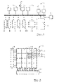
Fig. 2 shows in very schematic fashion some components of an image capturing device in the camera; -
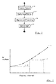
Fig. 3 is a flow diagram illustrating a method of capturing image frames and forming a combined final image,- -
Figs. 4A-4C show in very schematic fashion arrays of intensity values illustrating how the combined final image is formed in one embodiment ; and -
Fig. 5 is an illustration of noise levels of the image frames relative to the sensitivity of the human eye. - One example of an image processing system usable in the context of the methods outlined herein is a digital camera 1. Other examples include a photocopier or scanning device. The digital camera 1 comprises a lens system 2 for focusing on one or more objects in a scene. When a shutter 3 is opened, the scene is projected through an aperture 4 onto a photosensitive area 5 (
Fig. 2 ) of an image-capturing device 6. The shutter time is controllable, as is the diameter of the aperture. As an alternative, or addition, to the shutter 3, the image capturing device could be electronically controlled to provide the same effect (electronic shutter). The image capturing device 6 can be device implemented in Complementary Metal-Oxide Semiconductor (CMOS) technology, or a Charge-Coupled Device (CCD) sensor. The methods outlined herein are ideally suited to CCD sensors, which have the advantage of being cheap to manufacture, but have inherently long read-out times. - Referring to
Fig. 2 , the photosensitive area 5 is divided into areas occupied by pixel cells 7a-i, of which only nine are shown for clarity. Each pixel cell 7 includes a device for generating a signal indicative of the intensity of light to which the area that it occupies within the photosensitive area 5, is exposed. The device is, as stated, preferably a CCD sensor. It is noted that the devices occupying the pixel cells 7a-i are generally provided as components of one integrated circuit. An integral of the signal generated by a device is formed during exposure, for example by accumulation of photocurrent in a capacitor. Subsequent to exposure of the photo-sensitive area 5 for the duration of an exposure time interval, the values of the integrals of the generated signals are read out by means of row selection circuit 8 and column selection and readout circuit 9. - It is noted that, for simplicity, this description will not focus on the way in which colour images are captured. It is merely observed that any known type of technology can be used, such as colour filters, a colour-sensitive variant of the image capturing device 6, etc. In this respect, it is also observed that the photosensitive area 5 need not be the surface area of an integrated circuit comprised in an image-capturing device, or at least not for all colour components. Furthermore, although in the present application, image frames will be said to be captured consecutively, this does not preclude embodiments, wherein image frames of different colour components are captured in order, so that 'consecutively' captured image frames detailing one colour component are alternated by those detailing other colour components.
- The output of the column select and read-out circuit 9 is provided in the form of one or more analogue signals to an Analogue-to-Digital converter (A/D-converter) 10. The A/D-
converter 10 samples and quantises the signals received from the image capturing device 6, i.e. records it on a scale with discrete levels, the number of which is determined by the number of bits of resolution of the digital words provided as output by the A/D converter 10. The A/D converter 10 provides as output an array of pixel values encoding a captured image frame. - A Digital Signal Processor (DSP) 11 performs such features as interpolation between pixels and optionally compression of the image. Each exposure of the image-capturing device during an exposure time interval results in at least one frame.
- The digital camera 1 comprises a
storage device 12 for storing the image data encoding the captured images or image frames. The storage device can be any usual type of storage device, e.g. built-in flash memory, inserted flash memory modules, a disk drive with a floppy disk, a PCMCIA-format hard disk, or an optical disk drive. Amicroprocessor 13 controls the operation of the digital camera 1, by executing instructions stored in nonvolatile memory, in this example a Read-Only Memory (ROM) 14. The instructions inROM 14, in some embodiments in combination with routines programmed for execution by DSP 11, enable the digital camera 1 to execute the image processing and capturing methods outlined in the present application. - Advantageously, the
microprocessor 13 communicates with a co-processor 15 in which at least part of an image compression algorithm is implemented in hardware. Algorithms to compress images in accordance with the JPEG-standard are usable, for example. As part of the compression algorithm, the image data is transformed into the spatial frequency domain. The co-processor 15 executes at least this transformation, using a Discrete Cosine Transform (DCT) in most cases. Indications of the operating conditions and settings of the digital camera 1 are provided on anoutput device 16, for example a Liquid Crystal Display, possibly in combination with a sound-producing device (not illustrated separately). - An
input device 17 is shown schematically as being representative of the controls by means of which the user of the digital camera provides commands. In addition, the digital camera 1 illustrated inFig. 1 comprises aflash driver circuit 18 for providing appropriate driving signals to one or more sources of flash lighting. The illustrated digital camera 1 also comprises amotion sensor 19, for providing a signal representative of the movement of the digital camera 1, and thus of the image-capturing device 6. Furthermore, the digital camera 1 comprises anexposure metering device 20. The purpose of theexposure metering device 20 is to measure the strength of the ambient light, so that themicroprocessor 13 can deter- mine the intensity of light to be emitted by any connected flash, in combination with the correct values for the settings determining the exposure, which include the exposure time interval for each captured image frame, as will be elaborated on below. - It will be noted that the density of the areas occupied by the pixel cells 7a-i determines the maximum attainable spatial resolution of a captured image frame. The readout time depends on the number of pixel cells. It can be relatively long in embodiments such as the one illustrated in
Fig. 2 , because each row is selected in turn using row selection circuit 8, whereupon the column selection and readout circuit 9 senses the values of the accumulated photocharge stored in the photode- vices in the pixel cells in that row. To reduce the total time involved in repeatedly exposing the photosensitive area and capturing an image frame, the spatial resolution is set to a different value between exposures. - The
microprocessor 13 defines a number of cluster areas 21, which together cover a region corresponding to a region of interest in the combined final image. The number is smaller than the number of pixel cells 7a-i that together cover the region. Thus, a cluster of pixel cells occupies each defined cluster area 21, as is schematically illustrated inFig. 2 . For the sake of clarity, not all pixel cells 7 are shown. To capture an image frame at a lower spatial resolution, one pixel value per cluster area 21 is read out. To capture an image frame at the highest possible spatial resolution, one pixel value per pixel cell 7 is read out. Incidentally, although the cluster areas 21 as illustrated have been defined such as to partition the photosensitive area 5, themicroprocessor 13 may alternatively or additionally define a number of overlapping areas which together cover a region of the photosensitive area 5 corresponding to the region of interest. Alternatively, areas may be defined with a slight spacing between them. To avoid having to carry out compensatory processing, the defined areas each preferably surround regularly distributed pixel positions. - In one embodiment, the
microprocessor 13 controls the image-capturing device 6 in such a manner that the one pixel value read out per cluster area 21 represents an integral of the signal generated in one of the pixel cells 7 that lie within the cluster area 21. This embodiment has the virtue that it can be used with any type of image-capturing device 6. - In a preferred embodiment, the image-capturing device 6 has the capability to "bin" the outputs of multiple pixel cells. In this embodiment, the
microprocessor 13 directs. the image-capturing device 6 to generate an array of pixel values (each value being associated with one of the defined cluster areas 21) in such a manner that each pixel value is representative of the integral of the sum of the signals generated by at least two device in pixel cells that occupy the same defined cluster area 21. In this shown embodiment, this could mean that the pixel value for one cluster area 21 is the sum, or alternatively the average, of the integrals of the signal generated by all nine of the shown pixel cells 7a-7i. This embodiment is preferred, because it increases the sensitivity. Effectively, each pixel value represents the amount of light that fell on the whole of a defined cluster area 21, instead of just on the area occupied by one pixel cell 7. Thus, smaller light fluxes are detectable. Furthermore, binning decreases the amount of noise, i.e. leads to a low resolution image with a higher Signal-to-Noise-Ratio (SNR). As the binning capability is a function of the image-capturing device that is implemented in hardware, it does not add appreciably to the read out time. Preferably, the number of image frames that are captured at the highest resolution is equal to, more preferably lower than, the number of image frames captured at lower spatial resolutions. A combined final image formed on the basis of such a series of image frames will have a good SNR. - In a preferred embodiment, upon receiving a command from a user to capture an image, the
microprocessor 13 controls the digital camera 1 to carry out a series of steps 22-25. In one example, the command is alternatively received from a device (not shown) connected to the digital camera 1 through a suitable interface. This device issues an external trigger to start the execution of the illustrated steps. A user of the digital camera 1 may input a desired exposure time for a combined final image, together with settings determining the amount of flash light, the diameter of aperture 4 and the sensitivity of the photodevices in the pixel cells 7. In alternative embodiments, the microprocessor determines one or more of these values automatically, using a signal output by theexposure metering device 20, and possibly one or more pre-defined combinations of values. Subsequently, themicroprocessor 13, upon receiving a command actually to capture the combined final image, executes a first step 22 of capturing a number of image frames. This step 22 comprises retrieving the desired exposure time for the combined final image, determining the number of image frames to be captured and, for each image frame, calculating exposure settings determining an exposure level applicable to the image frame. The settings include the exposure time interval for the frame. Preferably, the other settings are determined such as to result in exposure time intervals for the image frames that, together, are shorter than the desired expo- sure time for the combined final image. It is noted that the embodiment in which "inning" is carried out allows a reduction in the exposure time interval applicable to the image frames, because binning increases the sensitivity. Effectively, 'binning' results in the introduction of an extra amplification of the photo-electric signal. Themicroprocessor 13 advantageously takes account of this. It calculates the length of the exposure time interval applicable to the image frame at a lower spatial resolution value in dependence on the spatial resolution value, i.e. the amount of "binning". - When calculating the settings determining the exposure levels applicable to the image frames, the
microprocessor 13 preferably implements one or more of the methods outlined in international patent applicationPCT/EP04/051080 - As mentioned above, the exposure level is determined by the exposure time, aperture, (flash) lighting intensity, and the amplifier gain in a pixel cell. It is further determined by the A/D conversion threshold of the A/
D converter 10. Stepping the amplification used to amplify an output of the photodevice in each pixel cell 7 has the advantage of easy implementation. In alternative embodiments, the exposure time for image frames of the same resolution is varied. In other embodiments, the maximum intensity of light admitted onto the photosensitive area is varied per image frame, for example by adjusting the size of the aperture 4, or the intensity of the flash controlled through theflash driver circuit 18. - In a first embodiment, the size of the aperture 4, as well as the lighting conditions, are kept constant between exposures. The desired exposure time for the combined final image is unevenly distributed over the image frames. Preferably, the number of image frames is selected to keep the exposure time interval for each image frame below a certain threshold level. Preferably, this threshold level is pre-determined at 1/60 second, as this is considered the lowest shutter speed to capture a steady image for the average photographer.
- In one variant, the exposure time is varied randomly between frames. In another embodiment, settings of the image capturing system, in this case the exposure time, are adjusted before several further captures of a frame in such a manner that least a maximum of the scale on which intensity values for each pixel are recorded changes substantially uniformly in value with each adjustment. This has the advantage of resulting in a more accurate capture of the colour and tonal depth in the combined final image. In each case, where binning is used to adjust the spatial resolution between captured frames as well, the impact on the exposure level is taken into account.
- In an alternative embodiment, the size of the aperture 4 is adjusted between two successive captures of an image frame in such a manner that at least a maximum of the scale on which intensity values for each pixel are recorded changes substantially uniformly in value with each adjustment. The exposure level is stepped down in equal increments by adjusting the aperture area. If no binning is applied, then the aperture area is stepped down in equal increments. Otherwise it is scaled with the multiplication factor resulting from basing each pixel value on the signals from multiple pixel cells.
- In yet another embodiment, the intensity of artificial light used to illuminate a scene to which the image- capturing device 6 is exposed is decreased in steps. Where the resolution decreases simultaneously, the intensity of artificial light is decreased by increasing amounts.
- Embodiments combining one or more of the techniques described in the preceding paragraphs are also conceivable.
- Following the first step 22 in which the image frames are captured, the arrays of pixel values encoding the image frames are cached in a
second step 23. Following thesecond step 23, they are aligned and processed in athird step 24. The combined final image resulting from the third step is stored instorage device 12 in afinal step 25. Although the present description will now continue on the assumption that the digital camera 1 carries out all of the steps 22-25, the third andfourth steps storage device 12 or transferring them to the computer via a data link (not shown). - Two embodiments of a method of forming a combined final image as performed in the course of executing
steps - In a first embodiment, as part of either the
second step 23 or thethird step 24, the set of captured image frames is converted in a set of adjusted image frames encoded by a corresponding set of arrays of pixel values. In this first embodiment, each pixel value in an array of intensity values encoding a captured image frame represents a light level in an area 21 surrounding one of a number of pixel positions. The number of pixel positions is proportional to the spatial resolution of the image frame, because the sizes of the respective image frames are the same. Each array of intensity values derived subsequently encodes an adjusted image frame based on one of the captured image frames. Each is generated in such a manner that each encodes at least a region of an adjusted frame at a desired resolution that is the same for each of the derived arrays. The region may correspond to the entire image frame, incidentally. Each array encoding an adjusted image frame is generated in such a manner that corresponding pixel values encoding the region in the arrays represent respective light level in an area surrounding substantially the same pixel position. That is to say, the ith pixel value of the pixel values of each array that encode the same region of interest corresponds to the same pixel position in each array for all values of i corresponding to a pixel position in the region of interest. - Because the spatial resolution differs between captured image frames, the spatial resolution of at least one of them must be adjusted by a multiplication factor, at least in the region of interest. Otherwise, it would not be possible to achieve the characteristic that each array of pixel values encoding an adjusted frame encodes at least the region of interest at the same spatial resolution. Preferably, the resolution of the lower-resolution frames is increased. This results in a combined final image with the highest possible perceived spatial resolution when the pixel values encoding the region are summed to form the combined final image. Any known technique to increase the spatial resolution may be applied, for instance interpolation.
- Then, the derived arrays of pixel values, encoding the image frames adjusted in resolution are used to generate an array of combined pixel values. Each element in this array is the sum of the corresponding elements of the derived arrays. In one example, the sum is a weighted sum. For example, the weights may be inversely related to the exposure times of the image frames. In another example, each combined pixel value is an average of the corresponding pixel values. The thus formed array is provided as output.
- A second embodiment of the method of forming a combined final image is illustrated in
Figs. 4A-4C . Afirst array 26 of pixel values encodes light intensity levels at each of a respective number of pixel positions in a first image frame. Each intensity value represents a light level in an area surrounding a pixel position. The same is true for asecond array 27 of pixel values, encoding a second image frame. The first and second image frames represent the same captured scene. It will be assumed herein that the image frames encoded by the first andsecond arrays - The
first array 26 of pixel values is divided into four blocks 28-31. Thesecond array 27 of pixel values is divided into the same number of blocks 32-35. A first block 28 in thefirst array 26 corresponds to afirst block 32 in thesecond array 27, i.e. represents a substantially overlapping section of the respective image frame. In the same manner, asecond block 29 in thefirst array 26 corresponds to asecond block 33 in the second array, athird block 30 corresponds to athird block 34 and afourth block 31 to afourth block 35 in thesecond array 27. Each of the blocks 32-35 in thesecond array 27 will be proportionally smaller in terms of the number of pixel values comprised therein than the corresponding one of the blocks 28-31 in thefirst array 26. In the example illustrated inFig. 4A , the low-resolution image frame is represented by thesecond array 27 comprising blocks of 2x2 pixel values, whereas the high-resolution image frame is represented by thefirst array 26, having 8x8 pixel values per block 28-31. Only the pixel values in thefirst blocks 28, 32 are shown inFig. 4A . - A discrete cosine transform into the spatial frequency domain is performed on a block-by-block basis. A
first array 36 of DCT coefficients (Fig. 4B ) is obtained by performing the DCT on thefirst array 26 representing the first image frame in the space domain. Asecond array 37 of DCT coefficients is obtained by performing a DCT on thesecond array 27. Thefirst array 36 andsecond array 37 of DCT coefficients encode light intensity levels at each of a respective number of pixel positions in the respective image frame, only then in the spatial frequency domain. The number of DCT coefficients determines the spatial resolution.
In a next step, fourDCT coefficients 38a-38d representing the lowest frequency components of the intensity distribution are derived from thefirst array 36 of DCT coefficients. FourDCT coefficients 39a-39d representing the components at the same frequency in thesecond array 37 of DCT coefficients are derived from that array. As the image frames have previously been aligned, the derived arrays represent light intensity levels at each of a common number of pixel positions in the first and second image frames. In the presented example, each derived array comprises four elements. - In a next step, an
array 40 of DCT coefficients encoding a combined image (in the spatial frequency domain) is generated. Thearray 40 is also divided into four blocks 41-44. Afirst block 41 is based on thefirst blocks 28, 32, asecond block 42 on thesecond blocks third block 43 on thethird blocks fourth block 44 is based on the values in thefourth blocks DCT coefficients 45a-d represent the lowest frequency components of the section of the combined final image encoded by thefirst block 41. They are each based on a sum of intensity values represented by thevalues 38a-d, 39a-d of the corresponding elements in the arrays derived from the first andsecond arrays first block 41 are based solely on those in the corresponding block of DCT coefficients in thefirst array 36 of DCT coefficients. They are thus based indirectly on the pixel values in the first block 28 of thefirst array 26 of pixel values. Thus, the combined final image is encoded at a higher resolution than the image frame represented by thesecond array 27 of pixel values. In the illustrated example the spatial resolution of the combined final image corresponds to that of the first image frame. In alternative embodiments, it has a value in between that of the first and second image frames. - The embodiment illustrated in
Figs. 4A-4C has a number of features that make implementation in the digital camera 1 attractive. There is no need to scale up thesecond array 27 of pixel values to the same number of pixel values as thefirst array 26. The interpolation that is thus avoided is particularly processing intensive, requiring a relativelypowerful microprocessor 13. The number of additions required to carry out summation of intensity values is also relatively limited, as only the derived arrays ofDCT coefficients 38a-d, 39a-d are added. Nevertheless, the combined final image is encoded at a resolution that is higher than that at which the low-resolution images on which it is based are encoded. This is the case because it is based on a sufficient number of the pixel values in thefirst array 26. - In an advantageous implementation, the transformation into the spatial frequency domain is carried out by using the
co-processor 15. It will be recalled that the co-processor 15 comprises an implementation in hardware of an image compression algorithm, for example to generate JPEG-compressed images. Themicroprocessor 13 is thus spared from having to compute the DCT coefficients in the first andsecond arrays - In one variant, the co-processor 15 converts the first and
second arrays microprocessor 13 carrying out the remaining steps in the method. In one implementation, the DCT coefficients are obtained by passing a null coefficient table for the entropy coding that is normally part of the image compression algorithm. - To achieve the property that each derived array encoding an adjusted image frame is generated in such a manner that corresponding intensity values encoding the region in the arrays represent light levels in an area surrounding the same pixel position, alignment using one or more of the methods outlined in
PCT/EP04/051080 - Following adjustment to align the image frames and provided them with the same spatial resolution, the combined final image is formed. This is done by forming an array of pixel values encoding the region in a combined final image, such that each pixel value in the formed array is the sum of the corresponding pixel values in the arrays of pixel values encoding the region in the adjusted image frames.
- It has been outlined above that the captured image frames with higher resolution have a higher noise level, and that binning reduces the noise level. This is visible in
Fig. 5 , which also illustrates the advantageous effects of a noise shaping technique used in the invention. The dashed line surrounding aleft-most area 46 delimits the boundaries of the range of frequency information contained in the binned, lower resolution image, as well as indicating the noise level. The dashed and dotted line surrounding aright-most area 47 does the same for a higher resolution image to which a high-pass digital filter has been applied. The digital high-pass filter may be applied prior to adjustment of the spatial resolution and/or alignment, or subsequent thereto. Without the application of the high-pass filter, theright-most area 47 would extend to the lower frequencies, at the same noise level. A continuous curve 48 representing the sensitivity of the eye of a human (or animal for that matter), demonstrates that the noise level of the higher-resolution image frame at lower frequencies would have been perceptible. The noise shaping achieved by means of capturing separate low-resolution image frames and high-resolution image frames and by subjecting the latter to a high-pass filter results in a combined final image with an acceptable noise level at all spatial frequencies. - The invention is not limited to the embodiments described above, which may be varied within the scope of the attached claims. The number of different levels of spatial resolution employed to capture the image frames for one combined final image can be two or higher. High-pass filtering and summation of pixel values may be carried out in an image processing system external to the digital camera 1. Alternatively, all steps prior to the actual summation of pixel values to form the array of pixel values encoding the combined final image may be carried out in the digital camera. Such adjusted image frames are then stored in the digital camera 1 for subsequent transfer to a computer or other image processing system. Furthermore, instead of underexposing each captured image, the gain of an amplifier between the output of the image capturing device (CCD or CMOS) and the A/D converter can be set very high. This results in an image with visible noise. The exposure is "correct", but the image has a lower quality than would be the case with a slower exposure. The methods outlined above improve the image quality in such an embodiment.
Claims (10)
- Method of forming a combined final image from a plurality of image frames, including the steps of:obtaining a first, and at least one further, array of intensity values, each array of intensity values encoding light intensity levels at each of a respective number of pixel positions in the respective image frame, the number determining the spatial resolution of the image frame concerned;generating a set of derived arrays of intensity values, each derived array being based on a respective one of the obtained arrays of intensity levels and encoding light intensity levels at each of a common number of pixel positions in at least a region of overlap of the respective image frames;generating an array of combined intensity values, each element in the array based on a sum of intensity values represented by the corresponding element in each of the respective derived arrays of intensity values; andproviding an array of intensity values encoding the combined final image, the array being based on the array of combined intensity values, wherein a first array of intensity values encoding at least the region of overlap at a higher resolution than the further arrays of intensity values is obtained, an array of intensity values encoding at least the region of overlap in the combined final image at a higher spatial resolution than the further arrays of intensity values is provided, characterised in that the array of intensity values encoding the combined final image is based on the required number of intensity values in the first array of intensity values to encode the region of overlap at a higher resolution than the further arrays of intensity values.
- Method according to claim 1, including obtaining first and further arrays of intensity values in which each intensity value represents a light level in an area surrounding a pixel position, wherein at least one derived array of intensity values is obtained by adjusting the number of intensity values in an array by a multiplication factor, such that each derived array encodes at least the region of overlap at the same spatial resolution.
- Method according to claim 2, wherein the number of intensity values in at least one array based on an obtained further array of intensity values is adjusted by a multiplication factor larger than one.
- Method according to claim 1, wherein each derived array of intensity values is generated by transforming an image frame encoded by an array of intensity values based on one of the obtained arrays of intensity values and in which each intensity value represents a light level in an area surrounding a pixel position in an image frame, into the spatial frequency domain, such that each intensity value in a derived array of intensity values represents an intensity of a spatial frequency component of the image frame.
- Method according to claim 4, wherein the step of providing the array of intensity values encoding the combined final image includes replacing at least one intensity value representing a low spatial frequency component in the derived array of intensity values based on the first obtained array of intensity values by an intensity value based at least partly on the intensity value representing the corresponding spatial frequency component in the array of combined intensity values.
- Method according to claim 4 or 5, wherein the transformation is carried out by a co-processor comprising at least a partial implementation in hardware of an image compression algorithm, or by a digital signal processor programmed to implement an image compression algorithm.
- Method according to any one of claims 1 to 6, wherein the step of generating an array of combined intensity values is preceded by a step of aligning the image frames, such that each derived array encodes light intensity levels at each of substantially corresponding pixel position in at least the region of overlap.
- Method according to any one of claims 1 to 7, wherein at least one array of intensity values, based on an obtained array of intensity values encoding at least the region of overlap in the respective image frame at a higher spatial resolution than at least one further array of intensity values, is subjected to a digital filter operation having a characteristic of passing high spatial frequency components of the image encoded by the array.
- Image processing system for forming a combined final image from a plurality of image frames, which image processing system includes:an arrangement for loading a first, and at least one further, array of intensity values, each array of intensity values encoding light intensity levels at each of a respective number of pixel positions in the respective image frame, the number determining the spatial resolution of the image frame concerned; anda data processing arrangement for processing the intensity values, wherein the system is configured to direct the data processing arrangement to perform the steps of generating a set of derived arrays of intensity values, each derived array being based on a respective one of the obtained arrays of intensity levels and encoding light intensity levels at each of a common number of pixel positions in at least a region of overlap of the respective image frames, generating an array of combined intensity values, each element in the array based on a sum of intensity values represented by the corresponding element in each of the respective derived arrays of intensity values, and providing an array of intensity values encoding the combined final image, the array being based on the array of combined intensity values, characterised in that the system is configured to:load a first array of intensity values encoding at least the region of overlap at a higher resolution than the further arrays of intensity values,provide an array of intensity values encoding at least the region of overlap in the combined final image at a higher spatial resolution than the further arrays of intensity values; andbase the array of intensity values encoding the combined final image on the required number of intensity values in the first array of intensity values to encode the region of overlap at a higher resolution than the further arrays of intensity values.
- Image processing system according to claim 9, configured to direct the processor to execute a method according to any one of claims 1 to 8.
Applications Claiming Priority (2)
| Application Number | Priority Date | Filing Date | Title |
|---|---|---|---|
| EP05749974A EP1883902B1 (en) | 2005-05-10 | 2005-05-10 | Method of controlling an image capturing system, image capturing system and digital camera |
| PCT/EP2005/052121 WO2006119802A1 (en) | 2005-05-10 | 2005-05-10 | Method of controlling an image capturing system, image capturing system and digital camera |
Related Parent Applications (1)
| Application Number | Title | Priority Date | Filing Date |
|---|---|---|---|
| EP05749974.1 Division | 2005-05-10 |
Publications (2)
| Publication Number | Publication Date |
|---|---|
| EP2273777A2 true EP2273777A2 (en) | 2011-01-12 |
| EP2273777A3 EP2273777A3 (en) | 2011-03-02 |
Family
ID=34980093
Family Applications (2)
| Application Number | Title | Priority Date | Filing Date |
|---|---|---|---|
| EP05749974A Not-in-force EP1883902B1 (en) | 2005-05-10 | 2005-05-10 | Method of controlling an image capturing system, image capturing system and digital camera |
| EP10183718A Withdrawn EP2273777A3 (en) | 2005-05-10 | 2005-05-10 | Method of controlling an image capturing system |
Family Applications Before (1)
| Application Number | Title | Priority Date | Filing Date |
|---|---|---|---|
| EP05749974A Not-in-force EP1883902B1 (en) | 2005-05-10 | 2005-05-10 | Method of controlling an image capturing system, image capturing system and digital camera |
Country Status (6)
| Country | Link |
|---|---|
| US (2) | US20080165258A1 (en) |
| EP (2) | EP1883902B1 (en) |
| JP (1) | JP4838302B2 (en) |
| CN (1) | CN101203884B (en) |
| AT (1) | ATE519180T1 (en) |
| WO (1) | WO2006119802A1 (en) |
Families Citing this family (19)
| Publication number | Priority date | Publication date | Assignee | Title |
|---|---|---|---|---|
| ATE519180T1 (en) | 2005-05-10 | 2011-08-15 | Active Optics Pty Ltd | METHOD FOR CONTROLLING AN IMAGE CAPTURE SYSTEM, IMAGE CAPTURE SYSTEM AND DIGITAL CAMERA |
| CN101305397B (en) * | 2005-10-12 | 2012-09-19 | 有源光学有限公司 | Method for forming image based on a plurality of image frames, image processing system and digital camera |
| US7889207B2 (en) * | 2007-02-08 | 2011-02-15 | Nikon Corporation | Image apparatus with image noise compensation |
| KR100950465B1 (en) * | 2007-12-21 | 2010-03-31 | 손승남 | Camera control method for vehicle enrance control system |
| JP4991602B2 (en) * | 2008-03-07 | 2012-08-01 | 富士フイルム株式会社 | Imaging device |
| US8963949B2 (en) | 2009-04-22 | 2015-02-24 | Qualcomm Incorporated | Image selection and combination method and device |
| US8537109B2 (en) * | 2009-05-14 | 2013-09-17 | Avago Technologies General Ip (Singapore) Pte. Ltd. | System and method for automatically adjusting light source drive current during optical navigation operation |
| CN102449663B (en) * | 2009-06-24 | 2015-02-11 | 诺基亚公司 | Device and method for processing digital images captured by a binary image sensor |
| US8724928B2 (en) | 2009-08-31 | 2014-05-13 | Intellectual Ventures Fund 83 Llc | Using captured high and low resolution images |
| US9204143B2 (en) | 2013-03-15 | 2015-12-01 | Samsung Electronics Co., Ltd. | Image sensor, operation method thereof, and system including the same |
| JP2015088786A (en) * | 2013-10-28 | 2015-05-07 | キヤノン株式会社 | Imaging apparatus, imaging system, control method of imaging apparatus, control method of imaging system, and program |
| JP6289184B2 (en) * | 2014-03-14 | 2018-03-07 | オリンパス株式会社 | Image recognition apparatus and image recognition method |
| JP6659163B2 (en) * | 2016-03-16 | 2020-03-04 | キヤノン株式会社 | Flash band determination device, control method thereof, and program |
| US20170294033A1 (en) * | 2016-04-06 | 2017-10-12 | Varex Imaging Corporation | Dose efficient x-ray detector and method |
| EP3416307B1 (en) * | 2017-06-12 | 2022-07-27 | STMicroelectronics (Research & Development) Limited | Vehicle communications using visible light communications |
| DE102017210845A1 (en) * | 2017-06-27 | 2018-12-27 | Conti Temic Microelectronic Gmbh | Camera apparatus and method for environmental detection of an environmental area of a vehicle |
| WO2019032792A1 (en) * | 2017-08-10 | 2019-02-14 | Robert Bosch Gmbh | Low power and low data-rate imager |
| CN111052633B (en) * | 2017-09-11 | 2023-06-06 | 昕诺飞控股有限公司 | Detecting coded light using a rolling shutter camera |
| EP4233306A1 (en) * | 2020-10-22 | 2023-08-30 | Qualcomm Incorporated | Mechanism for improving image capture operations |
Citations (7)
| Publication number | Priority date | Publication date | Assignee | Title |
|---|---|---|---|---|
| EP0358498A2 (en) | 1988-09-09 | 1990-03-14 | New York Institute Of Technology | Method and apparatus for generating animated images |
| US5657402A (en) | 1991-11-01 | 1997-08-12 | Massachusetts Institute Of Technology | Method of creating a high resolution still image using a plurality of images and apparatus for practice of the method |
| EP0940978A2 (en) | 1998-03-05 | 1999-09-08 | Hitachi, Ltd. | High resolution camera |
| US6590198B1 (en) | 1998-03-16 | 2003-07-08 | Photon Vision Systems, Inc. | Video bus for high speed multi-resolution imagers |
| WO2003084207A2 (en) | 2002-03-25 | 2003-10-09 | The Trustees Of Columbia University In The City Of New York | Method and system for enhancing data quality |
| US20050013509A1 (en) | 2003-07-16 | 2005-01-20 | Ramin Samadani | High resolution image reconstruction |
| WO2006119802A1 (en) | 2005-05-10 | 2006-11-16 | Andrew Augustine Wajs | Method of controlling an image capturing system, image capturing system and digital camera |
Family Cites Families (19)
| Publication number | Priority date | Publication date | Assignee | Title |
|---|---|---|---|---|
| US4647975A (en) * | 1985-10-30 | 1987-03-03 | Polaroid Corporation | Exposure control system for an electronic imaging camera having increased dynamic range |
| DE69127877T2 (en) * | 1990-11-22 | 1998-03-05 | Canon Kk | Imaging device |
| JPH04207581A (en) * | 1990-11-30 | 1992-07-29 | Canon Inc | Image pickup device |
| US5929908A (en) * | 1995-02-03 | 1999-07-27 | Canon Kabushiki Kaisha | Image sensing apparatus which performs dynamic range expansion and image sensing method for dynamic range expansion |
| US6429895B1 (en) * | 1996-12-27 | 2002-08-06 | Canon Kabushiki Kaisha | Image sensing apparatus and method capable of merging function for obtaining high-precision image by synthesizing images and image stabilization function |
| US6084229A (en) * | 1998-03-16 | 2000-07-04 | Photon Vision Systems, Llc | Complimentary metal oxide semiconductor imaging device |
| US6639626B1 (en) * | 1998-06-18 | 2003-10-28 | Minolta Co., Ltd. | Photographing apparatus with two image sensors of different size |
| US7038716B2 (en) * | 1999-07-30 | 2006-05-02 | Pixim, Inc. | Mobile device equipped with digital image sensor |
| JP3938833B2 (en) * | 2000-04-27 | 2007-06-27 | 株式会社リコー | Exposure control device |
| JP4554094B2 (en) * | 2001-01-26 | 2010-09-29 | オリンパス株式会社 | Imaging device |
| US7298402B2 (en) | 2000-10-26 | 2007-11-20 | Olympus Corporation | Image-pickup apparatus with expanded dynamic range capabilities |
| US6958778B2 (en) * | 2000-11-21 | 2005-10-25 | Hitachi Kokusai Electric Inc. | Iris control method and apparatus for television camera for controlling iris of lens according to video signal, and television camera using the same |
| US20040008269A1 (en) * | 2001-11-30 | 2004-01-15 | Assaf Zomet | System and method for providing multi-sensor super-resolution |
| US7123780B2 (en) * | 2001-12-11 | 2006-10-17 | Sony Corporation | Resolution enhancement for images stored in a database |
| JP4207581B2 (en) * | 2002-11-06 | 2009-01-14 | 日立化成デュポンマイクロシステムズ株式会社 | Heat-resistant photosensitive resin composition, method for producing relief pattern, and electronic component |
| JP3804617B2 (en) * | 2003-02-14 | 2006-08-02 | コニカミノルタフォトイメージング株式会社 | Image processing apparatus and method |
| WO2005122084A1 (en) | 2004-06-09 | 2005-12-22 | Active Optics Pty Ltd. | Method of motion correction in sequence of images |
| JP3988760B2 (en) * | 2004-08-17 | 2007-10-10 | 松下電器産業株式会社 | Solid-state imaging device |
| JP4765027B2 (en) * | 2005-07-29 | 2011-09-07 | 国立大学法人 奈良先端科学技術大学院大学 | Information processing apparatus and information processing system |
-
2005
- 2005-05-10 AT AT05749974T patent/ATE519180T1/en not_active IP Right Cessation
- 2005-05-10 US US11/913,819 patent/US20080165258A1/en not_active Abandoned
- 2005-05-10 EP EP05749974A patent/EP1883902B1/en not_active Not-in-force
- 2005-05-10 WO PCT/EP2005/052121 patent/WO2006119802A1/en not_active Application Discontinuation
- 2005-05-10 JP JP2008510418A patent/JP4838302B2/en not_active Expired - Fee Related
- 2005-05-10 EP EP10183718A patent/EP2273777A3/en not_active Withdrawn
- 2005-05-10 CN CN2005800497348A patent/CN101203884B/en not_active Expired - Fee Related
-
2011
- 2011-03-21 US US13/052,333 patent/US8619156B2/en not_active Expired - Fee Related
Patent Citations (7)
| Publication number | Priority date | Publication date | Assignee | Title |
|---|---|---|---|---|
| EP0358498A2 (en) | 1988-09-09 | 1990-03-14 | New York Institute Of Technology | Method and apparatus for generating animated images |
| US5657402A (en) | 1991-11-01 | 1997-08-12 | Massachusetts Institute Of Technology | Method of creating a high resolution still image using a plurality of images and apparatus for practice of the method |
| EP0940978A2 (en) | 1998-03-05 | 1999-09-08 | Hitachi, Ltd. | High resolution camera |
| US6590198B1 (en) | 1998-03-16 | 2003-07-08 | Photon Vision Systems, Inc. | Video bus for high speed multi-resolution imagers |
| WO2003084207A2 (en) | 2002-03-25 | 2003-10-09 | The Trustees Of Columbia University In The City Of New York | Method and system for enhancing data quality |
| US20050013509A1 (en) | 2003-07-16 | 2005-01-20 | Ramin Samadani | High resolution image reconstruction |
| WO2006119802A1 (en) | 2005-05-10 | 2006-11-16 | Andrew Augustine Wajs | Method of controlling an image capturing system, image capturing system and digital camera |
Also Published As
| Publication number | Publication date |
|---|---|
| EP1883902A1 (en) | 2008-02-06 |
| CN101203884B (en) | 2010-12-29 |
| EP2273777A3 (en) | 2011-03-02 |
| US8619156B2 (en) | 2013-12-31 |
| ATE519180T1 (en) | 2011-08-15 |
| JP4838302B2 (en) | 2011-12-14 |
| JP2008541584A (en) | 2008-11-20 |
| EP1883902B1 (en) | 2011-08-03 |
| WO2006119802A1 (en) | 2006-11-16 |
| US20080165258A1 (en) | 2008-07-10 |
| US20110228139A1 (en) | 2011-09-22 |
| CN101203884A (en) | 2008-06-18 |
Similar Documents
| Publication | Publication Date | Title |
|---|---|---|
| EP1883902B1 (en) | Method of controlling an image capturing system, image capturing system and digital camera | |
| Gu et al. | Coded rolling shutter photography: Flexible space-time sampling | |
| KR101348262B1 (en) | Method of forming a combined image based on a plurality of image frames | |
| KR101205842B1 (en) | Method of forming an image based on a plurality of image frames, image processing system and digital camera | |
| US7916181B2 (en) | Method and device for creating high dynamic range pictures from multiple exposures | |
| EP2191639B1 (en) | Correcting imaging device motion during an exposure | |
| JP4816336B2 (en) | Imaging method and imaging apparatus | |
| US5745808A (en) | Camera exposure control system using variable-length exposure tables | |
| US7940311B2 (en) | Multi-exposure pattern for enhancing dynamic range of images | |
| US8582814B2 (en) | Image processing method and system | |
| KR100914090B1 (en) | Image pickup apparatus | |
| JP4445567B2 (en) | Method and apparatus for generating photographs | |
| US7492391B1 (en) | Wide dynamic range network camera | |
| CN101616263B (en) | Image pick-up apparatus | |
| JPWO2006049098A1 (en) | Image sensor | |
| JP2002064754A (en) | Method and device for extending effective dynamic range of image pickup device | |
| JP5144739B2 (en) | Method for controlling image capturing system, image capturing system, and digital camera | |
| CN110233972A (en) | A kind of image capture method and device |
Legal Events
| Date | Code | Title | Description |
|---|---|---|---|
| PUAI | Public reference made under article 153(3) epc to a published international application that has entered the european phase |
Free format text: ORIGINAL CODE: 0009012 |
|
| AC | Divisional application: reference to earlier application |
Ref document number: 1883902 Country of ref document: EP Kind code of ref document: P |
|
| AK | Designated contracting states |
Kind code of ref document: A2 Designated state(s): AT BE BG CH CY CZ DE DK EE ES FI FR GB GR HU IE IS IT LI LT LU MC NL PL PT RO SE SI SK TR |
|
| PUAL | Search report despatched |
Free format text: ORIGINAL CODE: 0009013 |
|
| AK | Designated contracting states |
Kind code of ref document: A3 Designated state(s): AT BE BG CH CY CZ DE DK EE ES FI FR GB GR HU IE IS IT LI LT LU MC NL PL PT RO SE SI SK TR |
|
| RIC1 | Information provided on ipc code assigned before grant |
Ipc: H04N 5/335 20110101ALI20110124BHEP Ipc: G06T 5/50 20060101AFI20110124BHEP |
|
| RIN1 | Information on inventor provided before grant (corrected) |
Inventor name: WAJS, ANDREW AUGUSTINE |
|
| STAA | Information on the status of an ep patent application or granted ep patent |
Free format text: STATUS: THE APPLICATION IS DEEMED TO BE WITHDRAWN |
|
| 18D | Application deemed to be withdrawn |
Effective date: 20110903 |