EP2269928A2 - Apparatus and method for stacking sheets discharged from a starwheel assembly - Google Patents
Apparatus and method for stacking sheets discharged from a starwheel assembly Download PDFInfo
- Publication number
- EP2269928A2 EP2269928A2 EP10185647A EP10185647A EP2269928A2 EP 2269928 A2 EP2269928 A2 EP 2269928A2 EP 10185647 A EP10185647 A EP 10185647A EP 10185647 A EP10185647 A EP 10185647A EP 2269928 A2 EP2269928 A2 EP 2269928A2
- Authority
- EP
- European Patent Office
- Prior art keywords
- separator finger
- stack
- separator
- starwheel assembly
- sheets
- Prior art date
- Legal status (The legal status is an assumption and is not a legal conclusion. Google has not performed a legal analysis and makes no representation as to the accuracy of the status listed.)
- Granted
Links
Images


Classifications
-
- B—PERFORMING OPERATIONS; TRANSPORTING
- B65—CONVEYING; PACKING; STORING; HANDLING THIN OR FILAMENTARY MATERIAL
- B65H—HANDLING THIN OR FILAMENTARY MATERIAL, e.g. SHEETS, WEBS, CABLES
- B65H29/00—Delivering or advancing articles from machines; Advancing articles to or into piles
- B65H29/38—Delivering or advancing articles from machines; Advancing articles to or into piles by movable piling or advancing arms, frames, plates, or like members with which the articles are maintained in face contact
- B65H29/40—Members rotated about an axis perpendicular to direction of article movement, e.g. star-wheels formed by S-shaped members
-
- B—PERFORMING OPERATIONS; TRANSPORTING
- B65—CONVEYING; PACKING; STORING; HANDLING THIN OR FILAMENTARY MATERIAL
- B65H—HANDLING THIN OR FILAMENTARY MATERIAL, e.g. SHEETS, WEBS, CABLES
- B65H31/00—Pile receivers
- B65H31/30—Arrangements for removing completed piles
- B65H31/3081—Arrangements for removing completed piles by acting on edge of the pile for moving it along a surface, e.g. by pushing
-
- B—PERFORMING OPERATIONS; TRANSPORTING
- B65—CONVEYING; PACKING; STORING; HANDLING THIN OR FILAMENTARY MATERIAL
- B65H—HANDLING THIN OR FILAMENTARY MATERIAL, e.g. SHEETS, WEBS, CABLES
- B65H31/00—Pile receivers
- B65H31/32—Auxiliary devices for receiving articles during removal of a completed pile
-
- B—PERFORMING OPERATIONS; TRANSPORTING
- B65—CONVEYING; PACKING; STORING; HANDLING THIN OR FILAMENTARY MATERIAL
- B65H—HANDLING THIN OR FILAMENTARY MATERIAL, e.g. SHEETS, WEBS, CABLES
- B65H2301/00—Handling processes for sheets or webs
- B65H2301/30—Orientation, displacement, position of the handled material
- B65H2301/34—Modifying, selecting, changing direction of displacement
- B65H2301/341—Modifying, selecting, changing direction of displacement without change of plane of displacement
- B65H2301/3411—Right angle arrangement, i.e. 90 degrees
- B65H2301/34112—Right angle arrangement, i.e. 90 degrees changing leading edge
-
- B—PERFORMING OPERATIONS; TRANSPORTING
- B65—CONVEYING; PACKING; STORING; HANDLING THIN OR FILAMENTARY MATERIAL
- B65H—HANDLING THIN OR FILAMENTARY MATERIAL, e.g. SHEETS, WEBS, CABLES
- B65H2301/00—Handling processes for sheets or webs
- B65H2301/40—Type of handling process
- B65H2301/42—Piling, depiling, handling piles
- B65H2301/421—Forming a pile
- B65H2301/4212—Forming a pile of articles substantially horizontal
-
- B—PERFORMING OPERATIONS; TRANSPORTING
- B65—CONVEYING; PACKING; STORING; HANDLING THIN OR FILAMENTARY MATERIAL
- B65H—HANDLING THIN OR FILAMENTARY MATERIAL, e.g. SHEETS, WEBS, CABLES
- B65H2301/00—Handling processes for sheets or webs
- B65H2301/40—Type of handling process
- B65H2301/42—Piling, depiling, handling piles
- B65H2301/421—Forming a pile
- B65H2301/4217—Forming multiple piles
- B65H2301/42172—Forming multiple piles simultaneously
-
- B—PERFORMING OPERATIONS; TRANSPORTING
- B65—CONVEYING; PACKING; STORING; HANDLING THIN OR FILAMENTARY MATERIAL
- B65H—HANDLING THIN OR FILAMENTARY MATERIAL, e.g. SHEETS, WEBS, CABLES
- B65H2301/00—Handling processes for sheets or webs
- B65H2301/40—Type of handling process
- B65H2301/42—Piling, depiling, handling piles
- B65H2301/422—Handling piles, sets or stacks of articles
- B65H2301/4226—Delivering, advancing piles
- B65H2301/42264—Delivering, advancing piles by moving the surface supporting the lowermost article of the pile, e.g. conveyor, carriage
-
- B—PERFORMING OPERATIONS; TRANSPORTING
- B65—CONVEYING; PACKING; STORING; HANDLING THIN OR FILAMENTARY MATERIAL
- B65H—HANDLING THIN OR FILAMENTARY MATERIAL, e.g. SHEETS, WEBS, CABLES
- B65H2301/00—Handling processes for sheets or webs
- B65H2301/40—Type of handling process
- B65H2301/42—Piling, depiling, handling piles
- B65H2301/422—Handling piles, sets or stacks of articles
- B65H2301/4226—Delivering, advancing piles
- B65H2301/42266—Delivering, advancing piles by acting on edge of the pile for moving it along a surface, e.g. pushing
-
- B—PERFORMING OPERATIONS; TRANSPORTING
- B65—CONVEYING; PACKING; STORING; HANDLING THIN OR FILAMENTARY MATERIAL
- B65H—HANDLING THIN OR FILAMENTARY MATERIAL, e.g. SHEETS, WEBS, CABLES
- B65H2301/00—Handling processes for sheets or webs
- B65H2301/40—Type of handling process
- B65H2301/44—Moving, forwarding, guiding material
- B65H2301/445—Moving, forwarding, guiding material stream of articles separated from each other
- B65H2301/4454—Merging two or more streams
-
- B—PERFORMING OPERATIONS; TRANSPORTING
- B65—CONVEYING; PACKING; STORING; HANDLING THIN OR FILAMENTARY MATERIAL
- B65H—HANDLING THIN OR FILAMENTARY MATERIAL, e.g. SHEETS, WEBS, CABLES
- B65H2301/00—Handling processes for sheets or webs
- B65H2301/40—Type of handling process
- B65H2301/44—Moving, forwarding, guiding material
- B65H2301/447—Moving, forwarding, guiding material transferring material between transport devices
- B65H2301/4473—Belts, endless moving elements on which the material is in surface contact
-
- B—PERFORMING OPERATIONS; TRANSPORTING
- B65—CONVEYING; PACKING; STORING; HANDLING THIN OR FILAMENTARY MATERIAL
- B65H—HANDLING THIN OR FILAMENTARY MATERIAL, e.g. SHEETS, WEBS, CABLES
- B65H2301/00—Handling processes for sheets or webs
- B65H2301/40—Type of handling process
- B65H2301/44—Moving, forwarding, guiding material
- B65H2301/447—Moving, forwarding, guiding material transferring material between transport devices
- B65H2301/4478—Transport device acting on edge of material
-
- B—PERFORMING OPERATIONS; TRANSPORTING
- B65—CONVEYING; PACKING; STORING; HANDLING THIN OR FILAMENTARY MATERIAL
- B65H—HANDLING THIN OR FILAMENTARY MATERIAL, e.g. SHEETS, WEBS, CABLES
- B65H2404/00—Parts for transporting or guiding the handled material
- B65H2404/20—Belts
- B65H2404/26—Particular arrangement of belt, or belts
- B65H2404/269—Particular arrangement of belt, or belts other arrangements
- B65H2404/2693—Arrangement of belts on movable frame
-
- B—PERFORMING OPERATIONS; TRANSPORTING
- B65—CONVEYING; PACKING; STORING; HANDLING THIN OR FILAMENTARY MATERIAL
- B65H—HANDLING THIN OR FILAMENTARY MATERIAL, e.g. SHEETS, WEBS, CABLES
- B65H2513/00—Dynamic entities; Timing aspects
- B65H2513/40—Movement
- B65H2513/42—Route, path
-
- B—PERFORMING OPERATIONS; TRANSPORTING
- B65—CONVEYING; PACKING; STORING; HANDLING THIN OR FILAMENTARY MATERIAL
- B65H—HANDLING THIN OR FILAMENTARY MATERIAL, e.g. SHEETS, WEBS, CABLES
- B65H2555/00—Actuating means
- B65H2555/30—Multi-axis
Landscapes
- Engineering & Computer Science (AREA)
- Mechanical Engineering (AREA)
- Forming Counted Batches (AREA)
- Pile Receivers (AREA)
- Discharge By Other Means (AREA)
- Specific Conveyance Elements (AREA)
- Stacking Of Articles And Auxiliary Devices (AREA)
- Attitude Control For Articles On Conveyors (AREA)
- Electrical Discharge Machining, Electrochemical Machining, And Combined Machining (AREA)
Abstract
Description
- The invention relates to stacking sheets that are discharged from a starwheel assembly, and more specifically, to apparatuses and methods for continuously stacking discharged sheets without interrupting the rotation of the starwheel assembly.
- Many stacking devices are used to continuously create stacks of sheet products. In one common stacking device, the sheets are fed from a feeding system to the top of a wheel that is rotated about a wheel axis. The wheel includes a plurality of spiraled wheel blades or fins that project in a direction opposite to the direction of rotation. The sheets are fed between two adjacent fins and are rotated within the wheel to a lower position where the paper is stripped from the wheel by a barrier. The striped sheets fall away from the wheel onto a stacking plate located at the bottom of a stacking box. Different separators have been developed to separate two adjacent sheets being discharged from the wheel. The two adjacent sheets include a sheet that completes the stack of a specified number located in the stacking box and another sheet that begins a new stack on the separator.
- For example, some stacking devices rotate a separator about an axis that is displaced from the wheel axis but within the periphery of the wheel. The separator is rotated into a position between a first fed sheet that has just been fed into the wheel and an adjacent second sheet that will be fed into the wheel behind the separator as the wheel and separator rotate in the same direction. The separator rotates to the stacking position where the separator allows the first fed sheet to complete the stack located in the stacking box and supports the second fed sheet to begin a new stack at a position above the stacking plate of the stacking box. The separator accumulates additional sheets of the new stack to allow the completed stack to be sent to downstream operations, such as a packaging or bundling unit. When the stacking plate of the stacking box is cleared and ready to receive the new sheets accumulated by the separator, the separator rotates through the stacking box causing the sheets to fall onto the stacking plate located at the bottom of the stacking box.
- In the above-described device, the separator can strike the sheets that are not fully seated between the blades because the travel path of the separator intersects with the travel path of the blades. This undesirable contact is caused by rotating the separator about a different rotational axis than the wheel axis which causes portions of the path traveled by the separator to intersect the path traveled by the sheets carried on the wheel.
- Another type of conventional stacking device rotates a separator about the same axis as the wheel axis. The separator is coupled by an arm to the wheel axis, however the separator is at all times located outside a cylindrical volume that is defined by the periphery of the wheel. The separator rotates to a stacking position between a first sheet has been discharged from the wheel into the stacking box and a second sheet that is still located within the wheel. The separator allows the first sheet to fall to complete the stack located on a staking plate in the stacking box while the separator supports the second sheet above the completed stack as it is discharged from the wheel. The separator will support additional sheets while the stacking plate moves the completed stack to another location. The separator is limited to supporting only as many sheets as space permits because the separator is located a fixed distance from the periphery of the wheel. After the stacking plate returns to the stacking box and the stacking box is ready to accept the partially completed stack from the separator, the separator is rotated about the common axis. As the separator is rotated the barrier will strip the sheets from the separator and the sheets will fall onto the stacking plate that is located at the bottom of the stacking box.
- Another type of conventional separating device includes a separator that rotates about the wheel axis and moves radially away from the wheel axis once it is in the stacking position in order to accumulate additional sheets. The separator is rotated into a position between a first sheet that has just been fed into the wheel and a second sheet that will be fed into the wheel behind the separator as the wheel and separator rotate at the same speed about the common axis. The separator is rotated with the wheel until the separator is located at the stacking position beneath the wheel. The separator allows the first sheet to fall and complete the stack positioned on the stacking plate of the stacking box and supports the second sheet to begin the new stack on the separator. The separator finger moves radially away from the wheel to support additional sheets. Moving away from the wheel creates additional space to allow the separator to support more sheets than would be possible with a separator that did not move radially from the wheel. The stacking plate therefore has more time to move the completed stack because the separator can support an increased number of sheets before they must be transferred onto the stacking plate of the stacking box. When the stacking plate returns to the stacking box and is ready to accept the stack from the separator, the separator will rotate causing the barrier to push the sheets from the separator. The sheets then fall onto the stacking plate that is located at the bottom of the stacking box.
- Separators that are rotatably connected to the wheel axis often require a complex design that is limited in space about the axis of rotation of the wheel. The complexity of this configuration increases the cost of manufacturing and assembly costs associated with the separator. Inaccessibility of the components of such an intricate and compact design also tends to increase the maintenance and repair costs of the separator.
- In light of the above design requirements and limitations, a need exists for an apparatus that discharges sheets from a starwheel assembly which provides a separator that controllably moves between two adjacent sheets within the wheel without adversely affecting the position or movement of the sheets within the starwheel assembly, provides a separator that moves efficiently to enable the use of a simpler and less costly design, and provides a separator that is mounted to the frame outside of a cylindrical volume that is defined by the periphery of the wheel to simplify the design and manufacture, thereby minimizing manufacturing costs, maintenance costs, and repairs costs. Each preferred embodiment of the present invention achieves one or more of these results.
- In some preferred embodiments of the present invention, an apparatus and method are employed for discharging sheets from a starwheel assembly utilized for creating stacks of a desired number of sheets without interrupting the rotation of the starwheel assembly. Some embodiments of the present invention preferably separate sheets such that one separated sheet is allowed to fall and complete a stack and the other separated sheet is supported by a separator to begin a new stack. Preferably, the completed stack is transported away from the starwheel assembly by a conveyor as the new stack supports additional sheets that are discharged from the starwheel assembly. More preferably, the new stack will lower to provide clearance from the starwheel assembly to accumulate the additionally discharged sheets. The apparatus for discharging sheets preferably allows for cyclical repetition of the separation of the sheets, the stacking of the sheets, and the transportation of the stacks such that the continual rotation of the starwheel assembly is not interrupted.
- In some highly preferred embodiments of the present invention, the apparatus for discharging sheets from a starwheel assembly includes a barrier and a first separator finger. Preferably, the barrier is positioned adjacent to the starwheel assembly to discharge the sheets from the starwheel assembly. The first separator finger is movable and is preferably inserted between two adjacent sheets that are positioned within the starwheel assembly. More preferably, the first separator finger separates a first sheet of the two adjacent sheets from a second sheet of the two adjacent sheets. Even more preferably, the first separator finger supports a first sheet of the two adjacent sheets to begin a first stack upon the first separator finger and allows the second sheet of the two adjacent sheets to complete another stack.
- In one preferred embodiment of the present invention, the apparatus for stacking discharged sheets from a starwheel assembly includes a second separator finger. The second separator finger preferably works in coordination with the first separator finger to alternately separate adjacent sheets and support one of the separated sheets to create a second stack. The second separator finger is movable and preferably is inserted between a second set of two adjacent sheets that are positioned within the starwheel assembly. More preferably, the second separator finger separates a first sheet of the second set of two adjacent sheets from a second sheet of the second set of two adjacent sheets. Even more preferably, the second separator finger supports the first sheet of the second set of two adjacent sheets to begin a second stack upon the second separator finger and allows the second sheet of the second set of two adjacent sheets to complete the first stack on the first separator finger.
- In another preferred embodiment of the present invention, the apparatus for discharging sheets from a starwheel assembly includes the first separator finger and a movable conveyor. The movable conveyor preferably works in coordination with the first separator finger to receive and support the first stack from the first separator finger. Preferably, the movable conveyor moves toward the starwheel assembly to receive the partially completed first stack from the first separator finger. More preferably, the movable conveyor also moves away from the starwheel assembly axis to accommodate additional discharged sheets on the first stack. Preferably, the first separator finger is re-inserted between a second set of two adjacent sheets that are positioned within the starwheel assembly. The first separator finger can separate a first sheet of the second set of two adjacent sheets from a second sheet of the second set of two adjacent sheets. Also, the first separator finger preferably supports the first sheet of the second set of two adjacent sheets to begin a second stack upon the first separator finger and allows the second sheet of the second set of two adjacent sheets to complete the first stack on the movable conveyor. The movable conveyor carries the completed first stack away from the starwheel assembly while the first separator finger is accumulating intermediate sheets on the second stack.
- More information and a better understanding of the present invention can be achieved by reference to the following drawings and detailed description.
- The present invention is further described with reference to the accompanying drawings, which show preferred embodiments of the present invention. However, it should be noted that the invention as disclosed in the accompanying drawings is illustrated by way of example only. The various elements and combinations of elements described below and illustrated in the drawings can be arranged and organized differently to result in embodiments which are still within the spirit and scope of the present invention. In the drawings, wherein like reference numerals indicate like parts:
-
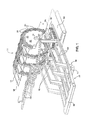
FIG. 1 is a perspective view of an apparatus for stacking sheets that are discharged from a starwheel assembly; -
FIG. 2 is a top view taken along lines 2-2 ofFIG. 1 , illustrating a first separator finger in the stacking position and a second separator finger in the starting position; -
FIG. 3 is a view similar toFIG. 2 , illustrating the second separator finger in the stacking position and the first separator finger in the starting position; -
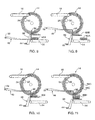
FIGS. 4-11 is a cross-section view taken along lines 4-4 ofFIG. 2 , illustrating the progressive motion of the first separator finger and the second separator finger; -
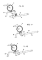
FIGS. 12-18 is a cross-section view of an apparatus according to a second preferred embodiment of the present invention, illustrating the progressive motion of a first separator finger and a movable conveyor; -
FIGS. 19-22 is an enlarged cross-section view similar toFIG. 4 , illustrating the movement of a separator finger being inserted between adjacent sheets within the starwheel assembly; -
FIG. 23 is a schematic view of the control system of the stacking apparatus shown inFIG. 1 ; -
FIG. 24 graphically illustrates the speed and position of the separator finger; -
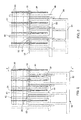
FIG. 25 is a perspective view of a conveyor system according to a preferred embodiment of the present invention; -
FIG. 26 is an enlarged perspective view of a first and second conveyor used in the preferred embodiment shown inFIG. 25 ; and -
FIG. 27 is a top view of the first and second conveyor shown inFIG. 26 . -
FIG. 1 illustrates an apparatus for stackingsheets 10 that are discharged from astarwheel assembly 14 embodying features of the present invention. The stackingapparatus 10 includes a frame (not shown) and astarwheel assembly 14. Thestarwheel assembly 14 rotates to accept sheets from afeeding system 16 and discharge the accepted sheets in another location. Thestarwheel assembly 14 preferably includes ashaft 18 and a plurality ofstarwheels 20. Theshaft 18 is rotatably coupled to the frame about anaxis 22 and is rotated by a motor (not shown) either directly or indirectly (e.g., via one or more gears, belts, chains, and the like drive by the motor, folding rolls, or other associated equipment). - Each
starwheel 20 is preferably coupled to theshaft 18 such that therotational axis 22 of theshaft 18 is located at the center of eachstarwheel 20. Preferably, eachstarwheel 20 is disk shaped and generally defines a diameter and a thickness. Alternatively, one or more starwheels 20 can comprise rods or other elongated structures of a generally star-shaped structure. Still other starwheel shapes are possible, each having a number of slots, grooves, recesses, or other types of apertures capable of receiving sheets of product therein for transport as the starwheels rotate. In some highly preferred embodiments, eachstarwheel 20 is preferably the same size and thickness. - Each
starwheel 20 of thestarwheel assembly 14 preferably includes a plurality offins 24 that project from the center of eachstarwheel 20. More preferably, eachfin 24 includes abase 26 and atip 28. Thetip 28 is positioned at a farther radial distance from the center of thestarwheel 20 than thebase 26. Thefins 24 are preferably the same uniform thickness as thestarwheel 20. Thefins 24 are preferably widest at thebase 26 and narrow to a point at thetip 28. In addition, thefins 24 preferably spiral in a uniform direction opposite to the direction of rotation and overlap withadjacent fins 24 such thatslots 30 are forked between twoadjacent fins 24. Eachslot 30 preferably spirals in the same direction as the direction of thefins 24, and is narrowest adjacent to thebase 26 of thefin 24 and widest at thetip 28 of thefin 24. Theslots 30 receive the sheets from thefeeding system 16 and support the sheets within thestarwheel assembly 14. until a force causes the sheets to be removed from theslots 30. - The size, shape, and number of
fins 24 included on each starwheel 20 can be varied. For example, each starwheel 20 can include as few as twofins 24 and as many as structurally possible. Thefins 24 can also project straight from the body of thestarwheel 20 or can be partially straight and partially curve. Thefins 24 can have a uniform width or can even become wider instead of tapering as they extend away from the center of thestarwheel 20. Thefins 24 can also be thinner or thicker than the thickness of thestarwheel 20. The configuration of theslots 30 are also variable to the extent theslots 30 are dependent upon the shape and number of thefins 24. - The
starwheel assembly 14 is not limited to having any particular number ofstarwheels 20, and can include onestarwheel 20 or more than twostarwheels 20 as may be required to support and convey larger sized sheets. When thestarwheel assembly 14 includes more than onestarwheel 20, it is preferable that eachstarwheel 20 includes the same number and configuration offins 24 andslots 30. Even more preferably, eachstarwheel 20 is coupled to theshaft 18 such that thefins 24 andslots 30 are oriented in the same angular position relative to the axis 22 (or preferably at least at substantially the same angular position in order to properly receive sheet product between thefins 24 ofmultiple starwheels 20. It should be noted that the starwheels can be different shapes, sizes or thicknesses as desired. - The stacking
apparatus 10 also includes abarrier 32 that contacts sheets that are within theslots 30 as thestarwheel assembly 144 rotates. Thebarrier 32 provides a force against one end of the sheet such that the sheet discharges from thestarwheels assembly 14 as thefin 24 on which the sheet rests continues to rotate past thebarrier 32. Thebarrier 32 is preferably stationary and preferably extends in a preferably radial direction below theaxis 22 of rotation. Thebarrier 32 alternatively can be positioned at any angular location within thestarwheel assembly 14. Thebarrier 32 can also be any shape that can provide a contact sulfate or point against which the sheets within thestarwheel assembly 14 abut, such as a pin, rod, plate, wedge, or tensioned wire. If desired, thebarrier 32 can also be moveable to discharge sheets from different angular positions about theaxis 22 of thestarwheel assembly 14. - The
barrier 32 is preferably coupled to the frame and is positioned betweenadjacent starwheels 20. In some embodiments havingmultiple starwheels 20 for conveying sheets, there can be fewer ormore barriers 32 than spaces betweenstarwheels 20. Accordingly, more than onebarrier 32 or nobarrier 32 can be located betweenadjacent starwheels 20 in thestarwheel assembly 14. However, at least onebarrier 32 is preferably located between or adjacent to each starwheel 20 or starwheel set used to received and convey a sheet. Thebarrier 32 preferably can be mounted to the frame through a linkage (not shown) or through any other structure capable of holding thebarrier 32 in place. Preferably, all of thebarriers 32 located betweenadjacent starwheels 20 of thestarwheel assembly 14 are connected by acommon support 36 which is connected to the frame. In the illustrated preferred embodiment, the linkage extends to the outside of thestarwheel assembly 14. Alternatively, thebarrier 32 can be coupled to theshaft 18 in a conventional manner such that thebarriers 32 does not rotate with theshaft 18. This can be accomplished by providing a non-rotating collar about the rotatingshaft 18. Also, thebarrier 32 can be weighted and mounted by a bearing that is connected to therotating shaft 18 such that thebarrier 32 is rotatable relative to theshaft 18 and biased by gravity toward the depending position. - It should be noted that throughout the specification and claims herein, when an element is said to be "within" the
starwheel assembly 14, it does not necessarily mean that the element is positioned within theslot 30 of thestarwheel 20 on thestarwheel assembly 14. Instead, something is "within" thestarwheel assembly 14 when the element or a substantial portion of the element is partially or fully located within a cylindrical volume that is defined by the periphery of thestarwheel 20 orstarwheels 20 of thestarwheel assembly 14 and that projects in a direction that is parallel to theaxis 22 of rotation. Likewise, when an element is described as being "outside" of thestarwheel assembly 14, the element or a substantial portion of the element is located outside of the cylindrical volume. By way of example, the farthest radially extending point located on thefins 24 during rotation of the starwheel orstarwheels 20 are located within thestarwheel assembly 14. - The
barrier 32 in part defines an area referred to as the drop-zone. The drop-zone is defined by an area projecting from thestarwheels assembly axis 22 in which the sheets are discharged from thestarwheel assembly 14 and stacked in a stack. Preferably, the drop-zone encompasses the area on the upstream side of thebarrier 32. More preferably, the drop-zone extends a radial distance past the circumference of thestarwheel assembly 14 that is greater than or substantially equal to the height of a stack of sheets. - The stacking
apparatus 10 is not required to be oriented such that thebarrier 32 is located directly below theaxis 22 of thestarwheel assembly 14 and thefeeding system 16 is positioned directly above thestarwheel assembly 14. Thefeeding system 16 and thebarrier 32 can be positioned at any angular location about theaxis 22 independent of each other. For example, thefeeding system 16 can be positioned to insert the sheets into thestarwheel assembly 14 at the ten o'clock position and thebarrier 32 can be positioned in the three o'clock position such that the sheets can be discharged from thestarwheel assembly 14 in a vertical orientation and stacked in a horizontal direction. - The
stalking apparatus 10 includes amovable separator finger 38 that separates adjacent sheets within thestarwheel assembly 14. In some highly preferred embodiments such as those shown in the figures, theseparator finger 38 8 is movable into and out of the drop-zone. Theseparator finger 38 is preferably coupled at one end to a linkage (not shown) that is coupled to the frame at a position located outside of thestarwheel assembly 14. The linkage is preferably adapted to move theseparator finger 38 in two dimensions defining a plane that is perpendicular to theaxis 22 of rotation. The linkage andseparator finger 38 can be actuated to move in this manner using a number of elements and devices well known to those skilled in the art, each of which falls within the spirit and scope of the present invention. - For example, the
separator finger 38 can be connected to a horizontal actuator and a vertical actuator so that theseparator finger 38 can be movable through a range of positions in a plane. The range of positions can be defined by the ranges of movement of the vertical and horizontal actuators and/or by the limitations of movement placed upon these actuators by conventional controller coupled thereto. One having ordinary skill in the art will appreciate that by controlling the vertical and horizontal actuators, theseparator finger 38 can preferably be placed in any position in the aforementioned plane and can preferably be moved through any desired path in the plane. Although such a range of movement is highly referred, this range of movement can be limited in any fashion in other embodiments as desired (e.g., limited from a region in the plane, limited horizontally or vertically, and the like. In some preferred embodiments, theseparator finger 38 is movable through a quadrangular path by actuation of the vertical and horizontal actuators. In other embodiments, theseparator finger 38 is movable through a closed path defining a triangular or other polygonal shape, an ellipse, circle, oval, or other curved path (including unusually shaped or complex curved paths), a path having any combination of straight and curved portions, and the like. - The area bounded by the path of motion of the
separator finger 38 preferably intersects the cylindrical volume of thestarwheel assembly 14 so that theseparator finger 38 is allowed to move within thestarwheel assembly 14. Also, theseparator finger 38 can be moved by actuating either the vertical or horizontal actuators in a series of actuations, by actuating the vertical and horizontal actuators at the same time or at substantially the same time, or by actuating either or both of these actuators as needed to generate the desired direction and path of finger movement. - The actuators are preferably conventional in nature, such as ball screws, linear bearings, motor-driven belts, chains, or cables, magnetic rails, linear motors, rack and pinion assemblies, hydraulic or pneumatic pistons, solenoids, or the like. One having ordinary skill in the art will appreciate that still other elements and assemblies for moving the
separator finger 38 through a desired path are possible and fall within the spirit and scope of the present invention. In some embodiments, theseparator finger 38 is capable of moving (via the actuators connected thereto) through a programmed series of movements, velocities, and accelerations in multiple directions as will be discussed further below. - In the illustrated preferred embodiment, the
separator finger 38 includes a plurality offingers 42 that extend in parallel directions relative to each other. Thefingers 42 are preferably straight rectangular bars that are connected together by across member 44. Thefingers 42 are preferably spaced such that when theseparator finger 38 is inserted into thestarwheel assembly 14 at least onefinger 42 is located betweenadjacent starwheels 20. Theseparator finger 38 can also include at least onefinger 42 that is positioned outside of the end starwheel 20 (or at least onefinger 42 positioned outside each end of the starwheel 20). Thefingers 42 of theseparator finger 38 are configured to support the sheets that are discharged from thestarwheel assembly 14. - Alternatively, the
separator finger 38 can include as few as asingle finger 42 that is insertable between twoadjacent starwheels 20 of thestarwheel assembly 14. In some embodiments, two ormore separator fingers 42 are received betweenadjacent starwheels 20 of thestarwheel assembly 14. If asingle starwheel 20 is used in thestarwheel assembly 14, one ormore fingers 42 can be positioned outside of thestarwheel 20 in an even or uneven manner. As long as at least onefinger 38 is employed as described herein, any number of fingers 38 (including no fingers 38) can be received within each space defined betweenadjacent starwheels 20 in thestarwheel assembly 14 and outboard of the end starwheels 20 in thestarwheel assembly 14. Thefingers 38 can occupy each space between the starwheels 20 or can occupy the spaces between the starwheels 20 in any pattern or in no pattern as desired. - The shape of the
fingers 42 can vary to support the sheets discharged from thestarwheel assembly 14. For example, thefinger 42 can be a pin, a horizontal plate, a rod, a beam or the like. Thefingers 42 can also be curved, bent, angled or any combination thereof. - In some embodiments of the invention, the stacking
apparatus 10 includes asecond separator finger 46 for separating adjacent sheets within thestarwheel assembly 14 independent of thefirst separator finger 38. Thesecond separator finger 46 preferably includes a linkage (not shown),fingers 50, and across member 52 similar to thefirst separator finger 38. Thesecond separator finger 46 is preferably moveable into and out of the drop-zone. Preferably, thesecond separator finger 46 is similarly attached to the frame and is capable of two dimensional movements that are preferably (but not necessarily) the same as thefirst separator finger 38. The first andsecond separator fingers FIGS. 4-11 and19-22 ) without interference. The first andsecond separator fingers separator fingers - The
barrier 32, thefirst separator finger 38, and thesecond separator finger 46 are mounted such that overlapping movement between thefirst separator finger 42, thesecond separator finger barrier 32 can be accomplished without interference. Preferably, this is accomplished by mounting thefingers second separator fingers cross-members fingers barriers 32 and each other. - Preferably, as viewed from
FIGS. 2 and 3 , thefingers 42 of thefirst separator finger 38, thefingers 50 of thesecond separator finger 46, and thebarrier 32 are spaced apart laterally betweenadjacent starwheels 20. For example, thefingers 42 of thefirst separator finger 38 can be positioned on one side of each space between the starwheels 20, with thefingers 50 of thesecond separator finger 46 positioned on the other side of each space between the starwheels 20, and thebarrier 32 positioned between thefingers second separator fingers fingers second separator fingers barrier 32 is positioned on the other side of each space between the starwheels 20. In some embodiments, those spaces of thestar wheel assembly 14 nearest the ends of thestarwheel assembly 14 havefingers - The relative order of the
fingers barrier 32 can be varied between theadjacent starwheels 20. In addition, any combination or number offingers barriers 32 can be present within each space betweenadjacent starwheel 20. For example, for astarwheel assembly 14 consisting of a series ofmany starwheels 20, afinger 42 of thefirst separator finger 38 can be positioned between alternatingadjacent starwheels 20 and thefingers 50 of thesecond separator finger 46 can be positioned between the remainingadjacent starwheels 20. Although any combination or variation of elements betweenadjacent starwheels 20 is within the scope of the present invention, it is preferred to position thefingers single separator finger separator finger 38 without any sag between thefingers barriers 32 spaced apart from each other along the length of thestarwheel assembly 14 such that the sheets are evenly stripped from thestarwheel assembly 14. - It should be noted that although the
barrier 32 and the first andsecond separator fingers barrier 32 can instead be connected directly to each of theseparator fingers separator finger 38 can include abarrier 32 that projects vertically from thefinger 42 such that when theseparator finger 38 is inserted through thestarwheel assembly 14, thebarrier 32 will strip the sheets from thestarwheel assembly 14. Thebarrier 32 that is mounted to theseparator finger 38 can be long enough to extend within thestarwheel assembly 14 even as theseparator finger 38 is moved radially away from thestarwheel assembly axis 22 to accommodate additional sheets. In some embodiments employing such abarrier 32, sheets can be discharged from thefinger fingers - The stacking
apparatus 10 can include aconveyor 54 that receives the stack from theseparator finger 38 and moves the stack away from thestarwheel assembly axis 22. Theconveyor 54 is preferably a conveyor belt that is configured to allow theseparator finger 38 to deposit the stack onto theconveyor 54 and to retract from theconveyor 54 such that the stack remains supported by theconveyor 54. Preferably, this can be accomplished by a series of grooves within the belt that are located at the same distances apart as thefingers 42 on theseparator finger 38. By way of this configuration, theseparator finger 38 supports the stack until it is lowered into the recesses at which time the stack is transferred to theconveyor 54 which will then support the stack. The recesses can be formed integrally with the belt or can be voids in theconveyer 54, thereby separating theconveyor 54 into a plurality of smaller belts. Thefingers 42 of theseparator finger 38 can preferably pass through the gaps between thesegmented conveyor 54 in order to transfer the stack from theseparator finger 38 to theconveyor 54. Theconveyor 54 need not be a conveyor belt, but instead can be anything that can move the stack away from thestarwheel assembly axis 22 such as a bucket, plate, box, arm, or support that is movable by other methods of conveyance known to those skilled in the art. - The stack can be transferred onto the
conveyor 54 from theseparator finger 38 by mechanisms that work independently of theconveyor 54. In one highly preferred embodiment illustrated in the figures, thebarrier 32 projects downward such that thebarrier 32 will strip the stack from theseparator finger 38 when theseparator finger 38 retracts from the front of thebarrier 32 to behind thebarrier 32 allowing the stack to drop onto theconveyor 54. Alternatively, one or more movable projections can be employed to sweep across thefingers 42 to eject the stack onto theconveyor 54. In addition, a conventional mechanism such as robotic grips or fingers can be used to grab the stack from theseparator finger 38 and move the stack onto theconveyor 54. Other manners of removing the stack from thefingers 42 are possible and would be recognized by one having ordinary skill in the art. -
FIG. 23 illustrates a control system for theapparatus 10, and particularly for controlling the movement of theseparator fingers control system 110 includes acontroller 112. Thecontroller 112 of one preferred embodiment is an ORION model controller produced by ORMEC Systems Corporation of Rochester, New York providing centralized control of theapparatus 10. In another preferred embodiment (not shown) the controller is a ControlLogix model controller produced by Allen-Bradley Corporation of Milwaukee, Wisconsin. Other commercially available or custom designed controllers can be easily substituted for these controllers and are considered as being within the scope of the invention such as, for example, various centralized and/or distributed control systems well-known to those stalled in the art. - In one preferred embodiment, the
controller 112 includes acentral processing unit 114 and a series of fouraxis cards central processing unit 114 via acommunications bus 124. Thecontrol system 110 preferably includes anencoder 126 connected to thefirst axis card 116. Theencoder 126 provides information to thecontroller 112 relating to the position of thestarwheel 20. Preferably, thecontrol system 110 also includes avertical drive motor 128 for thefirst separator finger 38. Thevertical drive motor 128 is preferably connected to thefirst axis card 116 through a data link 130 and electrical drive unit (not shown). Drive and control signals are transmitted from thecontroller 112 through theaxis card 116 and the data link 130 to thevertical drive motor 128 to control operation of themotor 128, and through themotor 128, provide vertical motion control of thefirst separator finger 38. Thevertical drive motor 128 is connected to thefirst separator finger 38 through an appropriate linkage (which is only shown schematically inFIG. 23 ). - The
control system 110 also preferably includes ahorizontal drive motor 132 for thefirst separator finger 38. Thehorizontal drive motor 132 is preferably connected to thesecond axis card 118 through adata link 134 and electrical drive unit (not shown). Drive and control signals are transmitted from thecontroller 112 through thesecond axis card 118 and the data link 134 to thehorizontal drive motor 132 to control operation of themotor 132, and through themotor 132, provide horizontal motion control of thefirst separator finger 38. Thehorizontal drive motor 132 is connected to thefirst separator finger 38 through an appropriate linkage (which is only shown schematically inFIG. 23 ). As described in greater detail below with respect to the overall operation of the stackingapparatus 10, the horizontal andvertical drive motors controller 112, preferably provide independent (i.e., asynchronous) vertical and horizontal control of theseparator finger 38. - The
control system 110 also preferably includes avertical drive motor 136 connected to thesecond separator finger 46 through thesecond axis card 118 and the correspondingdata link 138 and electrical drive unit (not shown), and ahorizontal drive motor 140 connected to thesecond separator finger 46 through athird axis card 120 and corresponding data link 142 and electrical drive unit (not shown). The second horizontal andvertical drive motors controller 112 to provide independent, (i.e., asynchronous) vertical and horizontal control of thesecond separator finger 46. - In some preferred embodiments such as that shown in the figures, the
control system 110 also includes anencoder 144 connected to thefourth axis card 122 of thecontroller 112 and amotor 146 for a wrapper unit (not shown) connected to thefourth axis card 122. Theencoder 144 andmotor 146 receive signals from thecontroller 112 to coordinate the operation of the wrapper unit with the stackingapparatus 10. Themotor 146 is preferably a belt drive motor, but provide driving power in any other manner (including without limitation by chain or cable drives, by suitable gearing, by direct or gearbox connection to the wrapper unit, and the like). Like theother motors wrapper unit motor 146 can be any conventional type of driving unit, such as an electric motor, an engine, a hydraulic motor, and the like. - Although the above-described control system for the stacking
apparatus 10 is most preferred, it should be noted that other control systems can be employed to perform the same vertical and horizontal finger positioning control functions. For example, PC-based control systems can be directly or indirectly connected tomotors fingers fingers motors fingers - The operation of a preferred embodiment of the stacking
apparatus 10 is illustrated inFIGS. 4-11 and24 .FIGS. 4-11 illustrate the operation of the preferred embodiment as viewed from the side of thestarwheel assembly 14 andFIG. 24 graphically illustrates the horizontal and vertical motion characteristics of theseparator finger 38 as it moves through its cycle. Specifically,FIG. 24 illustrates the horizontal speed and horizontal position of theseparator finger 38 and the independently controlled vertical speed and vertical position of theseparator finger 38 for 2 cycles (i.e., 2 seconds through 7 seconds and 7 seconds through 12 seconds). It should be noted that the inches referred to in the "Vertical Position" graph ofFIG. 24 are inches below a vertical starting position of theseparator finger 38, while the inches referred to in the "Horizontal Position" graph ofFIG. 24 are inches laterally beyond a horizontal starting position of theseparator finger 38. The two cycles illustrated represent a highly preferred motion profile generating superior results for stack separation in thestarwheel assembly 14. Although this profile is highly preferred, it should be noted that other motion profiles (e.g., different horizontal and vertical positions and paths, different horizontal and vertical speeds, etc.) can instead be used as desired. -
FIG. 4 illustrates thefirst separator finger 38 positioned in a starting position with thestarwheel assembly 14 continuously rotating in a clockwise direction (FIG. 24 , at 2 seconds). The starting position is located within thestarwheel assembly 14 and adjacent to thebarrier 32 such that thefinger 38 does not intersect therotating slots 30. Although not required, theseparator finger 38 in some embodiments is located entirely upstream of thebarrier 32 in this starting position. - The
feeding system 16 preferably inserts a sheet into each of theslots 30 on thestarwheels 20. The sheets are preferably fed into theslots 30 by thefeeding system 16 such that each sheet positioned against the crotch of theslot 30 between twoadjacent fins 24. Thefeeding system 16 is timed with the rotation of thestarwheel assembly 14 such that the sheets from thefeeding system 16 are inserted intosuccessive slots 30 on thestarwheels 20 while both thefeeding system 16 and thestarwheel assembly 14 run at substantially constant speeds. It is, however, not necessary that everyslot 30 on thestarwheel assembly 14 be fed with a sheet. Rather, any number ofslots 30 can remain empty between fed sheets within thestarwheel assembly 14. In fact, as little as one sheet can be fed per rotation of thestarwheel assembly 14. - The
fins 24 support the sheet in theslots 30 as thestarwheel assembly 14 rotates. The sheets preferably slide into theslots 30 until they contact the bottom of theslots 30. The sheets then rotate with thestarwheel assembly 14 until the radially inward ends of the sheets contact thebarrier 32 at acontact point 58 on thebarrier 32. Thebarrier 32 causes the sheet to be stripped from theslot 30 of thestarwheel 20. Thecontact point 58 between thebarrier 32 and the sheet moves downward away from theaxis 22 of thestarwheel assembly 14 as thestarwheel assembly 14 rotates until the entire sheet is pushed out of itsrespective slot 30. It should be noted that thebarrier 32 does not move the sheet out of theslot 30, but instead holds the sheet stationary as thestarwheel assembly 14 continues to rotate, thereby stripping the sheet from thestarwheel assembly 14. After the sheet is stripped from thestarwheel assembly 14 by thebarrier 32, the sheet is free to fall under the weight of gravity to begin, continue, or complete a stack of sheets. In other embodiments where the apparatus is oriented in different manners, the sheets can be stacked radially in other directions without the assistance of gravity. - Referring to the
FIGS. 5-7 , enlarged detailedFIGS. 19-22 , andFIG. 24 , thefirst separator finger 38 is inserted between two adjacent sheets located within the rotatingstarwheel assembly 14 to separate a last sheet of a stack from the first sheet of a new stack (FIG. 24 , beginning at 2.5 seconds). Once inserted between theslots 30, theseparator finger 38 preferably moves against the direction of rotation and downward until theseparator finger 38 is outside thestarwheel assembly 14 and in a position to support a discharged sheet (FIG. 24 , at 3 seconds). Theseparator finger 38 preferably moves from a position that is upstream of thebarrier 32. - With combined reference to
FIGS. 4-7 , it should be noted that the starting position of theseparator finger 38 illustrated inFIG. 4 is shown by way of example only, and that other starting positions of the separator finger are possible. As another example, theseparator finger 38 can be located at a greater radial distance from the starwheel axis, such as a location directly behind (downstream) of thebarrier 32. In such an embodiment, theseparator finger 38 can be moved horizontally or at an angle through thebarrier 32 and between two adjacent sheets located within the rotatingstarwheel assembly 14 in a manner similar to that described above. - The
separator finger 38 can be translated, rotated, or can have any combination of such movement through a linear and/or curved path. Although the paths taken by the individual fingers of theseparator finger 38 preferably lie substantially or entirely within respective planes, all or part of each finger can move out of such a plane if desired. In any case, theseparator finger 38 preferably follows a path of motion through thestarwheel assembly 14 betweenadjacent slots 30 in thestarwheels 20. The twoadjacent slots 30 include adownstream slot 30A located ahead of theseparator finger 38 in the direction of rotation and anupstream slot 30B behind theseparator finger 38 in the direction of rotation of thestarwheel assembly 14. - The path of motion of the
separator finger 38 is important so as not to interfere with the sheets that are rotating within thestarwheel assembly 14. In particular, theseparator finger 38 preferably moves in accordance with the following procedure: (i) thetip 28 of theseparator finger 38 is inserted between theadjacent slots 30 against the direction of rotation of the starwheel assembly 14 (FIGS. 19 and 20 ); (ii) thetip 28 of theslot 30 remains between the twoadjacent slots 30 as theseparator finger 38 continues to move until theseparator finger 38 is outside of the starwheels assembly 14 (FIGS. 21 and 22 ); (iii) once inserted between theadjacent slots 30, the top surface of theseparator finger 38 remains lower than the lowest point of theupstream slot 30; and (iv) the bottom surface of theseparator finger 38 remains above the uppermost point of thedownstream slot 30 that is located to the right of thebarrier 32. The movement of theseparator finger 38 is dependent upon the rotational speed of thestarwheel assembly 14 and is timed to prevent interference with the sheets within theslots 30. - As illustrated in
FIGS. 19-22 , thefirst separator finger 38 is inserted between thedownstream slot 30A and theupstream slot 30B and as a result betweensheet 56A andsheet 56B respectively. Thestarwheel assembly 144 continues to rotate and thefirst separator finger 38 continues to move through thestarwheel assembly 14 as described above. Thebarrier 32 will force thesheet 56A out of thedownstream slot 30A such that thesheet 56A will fall and complete thestack 56A below. The insertion of thefirst separator finger 38 is preferably programmed such that thesheet 56A will be the last sheet of a desired stack size (e.g., the 100th sheet of a 100 count stack). Theseparator finger 38 continues to move completely out of thestarwheel assembly 14 into a stacking position where theseparator finger 38 preferably supports thesheet 56B which has been discharged from theupstream slot 30B by thebarrier 32. Thesheet 56B is the first sheet of anew stack 60B that will begin to be built upon the first separator finger 38 (e.g., the 1st sheet of a new stack of 100 sheets). - With reference to
FIGS. 8-11 , additional discharged sheets fall to thestack 60B on thefirst separator finger 38. Preferably, theseparator finger 38 gradually moves radially away from theaxis 22 of rotation to provide adequate clearance from thestarwheel assembly 14 for the additional sheets (FIG. 24 , between 3 seconds and 5 seconds). The additionally stacked sheets therefore preferably fall onto the partially completedstack 60B the same distance from thestarwheel assembly 14 as a result of thefirst separator finger 38 moving radially away from theaxis 22 and the stack increasing. In other embodiments, theseparator finger 38 instead moves to a position permitting additional sheets to be stacked thereon without gradual movement of theseparator finger 38 away from theaxis 22 of rotation. Accordingly, a separator finger that is held stationary to support additional sheets after it moves through the starwheel assembly is within the scope of the present invention. - The operation of the
second separator finger 46 will now be discussed in detail, but will not be shown specifically in the drawings as thesecond separator finger 46 preferably progresses through similar movement as thefirst separator finger 42 described above and shown inFIGS. 4-11 . Thesecond separator finger 42 will preferably follow the movements and accelerations of thefirst separator finger 38 shown inFIG. 24 , except that the second separator finger will be 180 degrees out of phase (i.e., offset by 3.5 seconds for the illustrated embodiment). Thesecond separator finger 46 is moved to the starting position as the additional sheets are being stacked on thestack 60B that is supported by thefirst separator finger 38. Thesecond separator finger 46 is inserted between twoadjacent slots 30 such that the downstream slot 30C possesses thesheet 56C that will complete thestack 60B on the first separator finger 38 (e.g., the 100th sheet) and the upstream slot 30D possesses thefirst sheet 56D of a new stack (e.g., the 1st sheet) (FIG. 11 ). Thesecond separator finger 46 moves through thestarwheel assembly 14 to the stacking position. Thesecond separator finger 46 allows thesheet 56C to fall and complete thestack 60B supported by thefirst separator finger 38 and supports thesheet 56D that is stripped from thestarwheel assembly 14 by thebarrier 32. Thesecond separator finger 46 moves radially away from thestarwheel assembly axis 22 to provide additional space to accommodate additional discharged sheets on the stack. - After the
second separator finger 46 interrupt stacking of discharged sheets onto thefirst separator finger 38, thefirst separator finger 38 preferably moves toward theconveyor 54. Thestack 60B is then transferred to theconveyor 54, after or during which time thefirst separator finger 38 moves away from the conveyor 54 (FIG. 24 , between 5.5 and 6 seconds). Thestack 60B can be transferred to theconveyor 54 in any of the manners described above. In the illustrated preferred embodiment for example, thestack 60B is transferred by drawing thefirst separator finger 38 through thebarrier 32. Thefirst separator finger 38 then preferably returns to the starting position to repeat the cycle when the downstream slot of twoadjacent slots 30 includes the last sheet that will complete the stack on the second separator finger 46 (FIG. 24 , between 6 seconds and 7 seconds). Theconveyor 54 moves thestack 60B away from thestarwheel assembly axis 22 to create room for the next stack to be placed on theconveyor 54 by thesecond separator finger 46. - In the embodiment shown in
FIGS. 4-11 , thefirst separator finger 38 and thesecond separator finger 46 work in succession to stack discharged sheets from thestarwheel assembly 14 and transfer the stack of a preferably predetermined number to aconveyor 54 without interrupting the rotation of thestarwheel assembly 14. The first andsecond separator fingers separator fingers separator fingers separator finger 38, 4.6 can pause in the starting position until the last sheet that completes a partially completed stack needs to be separated from a new sheet that begins a new stack on the inserted separator finger. - In an alternative embodiment, the
second separator finger 46 preferably operates to receive partially completed stacks from thefirst separator finger 38. During operation of this embodiment, thefirst separator finger 38 preferably transfers the partially completed stack to thesecond separator finger 46 and then returns to the starting position. Thesecond separator finger 46 preferably moves radially away from thestarwheel axis 22 in order to accumulate additional sheets on the partially completed stack. Once the desired number of sheets have been stacked on thesecond separator finger 46, thefirst separator finger 38 is re-inserted between twoadjacent slots 30 such that thedownstream slot 30 possesses the sheet that will complete the stack on thesecond separator finger 46. Thefirst separator finger 38 then preferably begins moving radially away from thestarwheel axis 22 to accumulate additional sheets while thesecond separator finger 46 moves to transfer the completed stack onto theconveyor 54. After the stack is transferred, the conveyor 544 preferably moves the stack away from thestarwheel assembly 14 and thesecond separator finger 46 moves toward thestarwheel axis 22 to again receive the partially completed stack from thefirst separator finger 38. - It should be noted that at extremely high speeds (i.e., above 80% of the maximum rated speed for the illustrated embodiment), the
fingers separator fingers fingers separator fingers separator fingers separator fingers 38, 46) to dampen the vibrations caused by operation at such high speeds. By way of example only, the separator fingers are made at least partially of steel, and each have a 0.002" thick layer of viscoelastic damping material (e.g.,ISD 112 viscoelastic polymer manufactured by 3M®) sandwiched between the finger and a 0.015" thick constraining layer of steel. One having ordinary skill in the art will appreciate that still other constrained layer damper materials and constructions are possible, each falling within the spirit and scope of the present invention. - In an alternative embodiment shown in
FIGS. 12-18 , the stackingapparatus 10 includes asingle separator finger 38 and amovable conveyor 62. Theseparator finger 38 and themovable conveyor 62 work in succession to consistently stack discharged sheets from thestarwheel assembly 14 and move the stack on themovable conveyor 62 away from thestarwheel assembly axis 22, without interrupting the rotation of thestarwheel assembly 14. Themovable conveyor 62 moves towards thestarwheel assembly axis 22 to receive the stack from theseparator finger 38 and away from thestarwheel assembly axis 22 to accumulate additional sheets that are discharged from thestarwheel assembly 14. Themovable conveyor 62 includes afirst conveyor belt 64 that is rotatably coupled to asecond conveyor belt 66, but can take any form of conveyor as described above with reference toconveyor belt 54, including a single conveyor belt translatable and/or rotatable with respect to thestarwheels 20. In each alternative case, theconveyor 62 is preferably movable toward and away from thestarwheel assembly axis 22. Thesecond conveyor belt 66 is preferably pivotally coupled to the frame such that thefirst conveyor belt 64 is movable by thesecond conveyor belt 66. It is not necessary that themovable conveyor 62 be a series of conveyor belts (as discussed above, themovable conveyor 62 can take other formes). - Although a
movable conveyor 62 is highly preferred to enable the stack to be transferred from theseparator finger 38 to themovable belt 62 without significant disturbance, theconveyor 62 need not necessarily move in some embodiments. For example, for relatively short count stacks, theconveyor 62 can be located closer to thestarwheel assembly 14 and need not move (or even be movable) toward and away from thestarwheel assembly 14. - The operation of this embodiment of the stacking
apparatus 10 is illustrated inFIGS. 12-18 . During operation of this embodiment, theseparator finger 38 begins in the starting position as shown inFIG. 12 and is inserted between twoadjacent slots 30 in a similar manner as described above. After theseparator finger 38 is moved outside of the starwheel assembly 144 (FIG. 13 ), theseparator finger 38 supports thefirst sheet 56B and preferably moves radially away from thestarwheel assembly axis 22 to accept additional discharged sheets (FIGS. 13-16 ). - Referring to
FIG. 17 , themovable conveyor 62 moves toward thestarwheel assembly axis 22 to receive the stack B from theseparator finger 38. As shown inFIG. 18 , theseparator finger 38 retracts from themovable conveyor 62 to transfer the partially completedstack 60B on themovable conveyor 62. Themovable conveyor 62 preferably moves radially away from thestarwheel assembly axis 22 to provide additional clearance to accommodate additional discharged sheets. In such embodiments, the discharged sheets will preferably fall approximately the same distance to the top of the partially completed stack as themovable conveyor 62 moves away from thestarwheel assembly axis 22 and thestack 60B size increases. In similar fashion to that shown inFIGS. 12-13 , theseparator finger 38 moves back into the starting position and is inserted between twoadjacent slots 30 such that thedownstream slot 30 possesses thesheet 56 that will complete thestack 60 on themovable conveyor 62. - Similar to
FIG. 14 , once thestack 60 on themovable conveyor 62 is completed by thelast sheet 56 and theseparator finger 38 begins building anew stack 60, themovable conveyor 62 moves thestack 60 away from thestarwheel assembly axis 22. After thestack 60 is moved away (e.g.,FIGS. 15 and16 ), themovable conveyor 62 can be moved toward thestarwheel assembly axis 22 to again receive the partially completedstack 60 from the separator finger 38 (e.g.,FIGS. 17 and 18 ). - It is possible for the
movable conveyor 62 to start moving toward thestarwheel assembly axis 22 while themovable conveyor 62 is moving a stack away from thestarwheel assembly axis 22. This dual motion can be necessary when the stack heights are so small that there is minimal time between when the stack is completed on themovable conveyor 62 and when themovable conveyor 62 must receive the new partially completed stack from theseparator finger 38. Alternatively, pausing between such motions of themovable conveyor 62 is possible when the stack height is sufficiently large to extend the cycle time of the stackingapparatus 10. - An important advantage provided by the
separator fingers horizontal drive motors separation fingers - In contrast, the
separator fingers separator fingers horizontal drive motors separator fingers controller 112 of acontrol system 110. Thiscontrol system 110 is preferably operable by a user to change the manner in which the vertical andhorizontal drive motors separator fingers - Preferably, the
separator fingers separator fingers 38, 4.0 are therefore mechanically unconstrained to move in the plane and can be constrained by control of the vertical and horizontal actuators to move through any one of a number of desired paths based upon the operation of thestarwheel assembly 14 and the type of product being run. Because separator finger motion can be changed by changing the actuation time and speed of the horizontal and vertical actuators driving theseparator fingers separator fingers separator finger controller 112. In some preferred embodiments, the programs that control the motion of theseparator fingers starwheel assembly 14. - By employing
separator fingers 3 8, 46 that are movable in any selected path in a range of motion as described above, the stackingapparatus 10 of the present invention is capable of producing a large number of different package sizes and types with little or no machine downtime or changeover. For example, in some embodiments, thefingers separator fingers drive motors - In some highly preferred embodiments of the present invention, two
separator fingers multiple separator fingers separator fingers separator fingers FIGS. 4-11 and19-22 , onefinger product fingers separation fingers - Another embodiment of the present invention is illustrated in
FIG. 25 and is preferably capable of producing multiple stacks of product frommultiple starwheels 20 rotating about acommon starwheel axis 22. Only twostarwheels 20 are shown inFIG. 25 for the sake of simplicity. The stacks of product are preferably aligned or substantially aligned along thestarwheel assembly 14 in the same or similar manner as described above with regard to the preferred embodiments illustrated inFIGS. 1-24 . However, such aligned stacks of product can be produced in any other manner desired from any other upstream equipment. In the case of thestarwheel assemblies 14, the stacks of product can be transferred to the conveyors in any of the manners described above with regard to the starwheel assemblies illustrated inFIGS. 1-24 . - As shown in
FIGS. 25 and26 , this embodiment preferably includes afirst conveyor 68 and asecond conveyor 70. Thefirst conveyor 68 is aligned with a first starwheel assembly 14A and thesecond conveyor 70 is aligned with asecond starwheel assembly 14B such that thefirst conveyor 68 receives completed stacks from the first stackingapparatus 10A and thesecond conveyor 70 receives completed stacks from the second stackingapparatus 10B. For purposes of description and illustration, each stackingapparatus starwheel assembly 14A, 14B preferably includes the same elements described above with regard to the starwheel assembly embodiments illustrated inFIGS. 1-24 , and share a common pivot about which thestarwheels 20 rotate. Each stackingapparatus starwheel assembly 14A, 14B can have any number ofstarwheels 20 as described in greater detail above (only one is shown inFIG. 25 for each stackingapparatus starwheel assembly 14A, 14B). - As mentioned earlier, the
conveyors apparatuses first conveyor 68 moves at a first speed and thesecond conveyor 70 moves at a second speed that is slower than the first speed of thefirst conveyor 68. The first andsecond conveyors common motor 72, althoughdedicated motors 72 driving the first andsecond conveyors conveyors - The
first conveyor 68 and thesecond conveyor 70 are preferably coupled to themotor 72, by afirst gear 74 and asecond gear 76, respectively, such that thefirst conveyor 68 moves faster than thesecond conveyor 70. The first andsecond gears belts 80A, 80B. The speed differential can be accomplished by a speed reducer located between themotor 72 and thesecond gear 76, a speed accelerator located between themotor 72 and thefirst gear 74, or a largerfirst gear 74 compared to thesecond gear 76. Any of these methods have the effect of creating different gear ratios between thefirst conveyor 68 and thesecond conveyor 70 such that the speed of thefirst conveyor 68 is different from the speed of thesecond conveyor 70. Likewise, theconveyors motor 72 need not be coupled by gears, but instead themotor 72 can be coupled to theconveyors conveyors FIG. 26 . - A
paddle conveyor 82 is preferably used in combination with multiple stackingapparatuses paddle conveyor 82 is preferably located at downstream ends 86A, 86B of the first andsecond conveyors conveyors conveyors paddle conveyor 82 near the downstream ends 86A, 86B of theconveyors paddle conveyor 82 can include abackstop 88 that stops the momentum of the stacks and prevents the transferred stacks from sliding past thepaddle conveyor 82. - The
paddle conveyor 82 preferably includes a plurality ofpaddles 90 that move transversely relative to the direction of movement of theconveyors first conveyor 68 is preferably located in the upstream direction of thepaddles 90 from thesecond conveyor 70 such that thepaddles 90 will move past thedownstream end 86B of thesecond conveyor 70 before thepaddles 90 will move past thedownstream end 86A of thefirst conveyor 68. Thepaddles 90 each preferably include astem 92 that extends through a slot 944 in thepaddle conveyor 82 and apusher 96 that is connected to thestem 92 such that thepusher 96 contacts the stack and moves the stack in the direction of thepaddles 90. The stems 92 of thepaddles 90 are preferably connected to a paddle belt 98 below thepaddle conveyor 82 such that thepaddles 90 continuously raise up on anupstream end 100 of thepaddle conveyor 82, move over the length of thepaddle conveyor 82 to contact the stacks, and lower on thedownstream end 102 of thepaddle conveyor 82 to unload the stacks. Thepaddles 90 then preferably rotate below thepaddle conveyor 82 along the length of the paddle belt 98 and return to theupstream end 100. - The operation of this preferred embodiment of the present invention will now be described with reference to
FIG. 25-27 . Initially, the first stackingapparatus 10A discharges afirst stack 60A onto theupstream end 86A of thefirst conveyor 68 and the second stackingapparatus 10B discharges asecond stack 60B on theupstream end 86B of thesecond conveyor 70 at substantially the same time. Theconveyors stacks second stack 60B' is moved toward thedownstream end 86B of thesecond conveyor 70 at a speed that is less than the speed of thefirst stack 60A'. This speed differential permits thepaddle conveyor 82 to receive and transport stacks of product away from theconveyors paddle conveyor 82 havingpaddles 90 spaced a shorter distance than the distance between centerlines of theconveyors 68, 70 (a possible design selection based upon downstream equipment, desired paddle conveyor speeds, and other considerations). Theconveyors stacks paddle conveyor 82 where thestacks backstop 88 to retain thestacks paddle conveyor 82. - A number of different conventional devices and strictures can be employed to improve the transfer of
stacks conveyors paddle conveyor 82. By way of example only, an air table (not shown) can be positioned between the downstream ends 86A, 86B of theconveyors paddle conveyor 82 in order to reduce friction beneath thestacks stacks paddle conveyor 82. Alternatively, part or all of thepaddle conveyor 82 itself can be an air table provided with fluid under pressure (supplied to the surface of the table through apertures in the paddle conveyor 82) to perform this same function. In another embodiment, at least part of the paddle conveyor and/or at least part of theconveyors stacks paddle conveyor 82 from theconveyors conveyors paddle conveyor 82. In other embodiments, one or more fingers, arms, plates, paddles, or other devices driven in any conventional manner can be actuated to sweep, push, pull, or otherwise movestacks conveyors paddle conveyor 82. Any other conveying device or system capable of transferring product between conveyors can be used to transfer thestacks - After the
first stack 60A" has been received on the paddle conveyor 82 (in some preferred embodiments, after a side of thefirst stack 60A" contacts the backstop 88), afirst paddle 104 of the plurality ofpaddles 90 pushes thefirst stack 60A"' in the downstream direction of thepaddles 90. Preferably, after thefirst paddle 104 passes thesecond conveyor 70 and thesecond stack 60B" can be transferred to thepaddle conveyor 82 without interfering with thefirst paddle 104, thesecond stack 60B"' moves onto thepaddle conveyor 82. Preferably in a manner similar to thefirst stack 60A, asecond paddle 106 of the plurality ofpaddles 90 preferably pushes thesecond stack 60B"' in the downstream direction of thepaddles 90. Theconveyors paddles second paddle 106 immediately follows thefirst paddle 104. However, thesecond paddle 106 can follow thefirst paddle 104 at any desired time after passage of thefirst paddle 104. Both of thestacks 60A"', 60B"' move downstream with thepaddles 60A"', 60B"' until they are unloaded off of thedownstream end 102 of thepaddle conveyor 82 to be delivered to downstream operations (for example, to a wrapping apparatus, not shown). - Although the embodiment described above with reference to
FIGS. 25-27 is shown comprising two stackingapparatuses conveyors paddles 90 are allowed to move a single stack at a time without interfering with another stack. - The embodiments described above and illustrated in the drawings are presented by way of example only and are not intended as a limitation upon the concepts and principles of the present invention. As such, it will be appreciated by one having ordinary skill in the art that various changes in the elements and their configuration and arrangement are possible without departing from the spirit and scope of the present invention as set forth in the appended claims. For example, the conveyor assembly described above and illustrated in
FIGS. 25-27 preferably employsbelt conveyors stacks starwheels 20 and apaddle conveyor stacks belt conveyors belt conveyors paddle conveyor FIGS. 1-27 ), including without limitation belt, chain, tabletop, paddle, and bucket conveyors driven in any conventional manner. Similarly, although a paddle conveyor is preferred for transportingstacks paddle conveyor - Although the
separator fingers vertical drive motors separator fingers separator fingers separator fingers separator fingers separator fingers fingers - One having ordinary skill in the art will appreciate that any path of separator finger motion can be generated by actuation of either actuator or by simultaneous, substantially simultaneous, or staggered actuation of two or more actuators connected to the
separator fingers - The paths of motion taken by the
separator fingers separator fingers separator fingers starwheels 20 as described above and to retract theseparator fingers separator fingers separator fingers -
- 1. An apparatus for stacking sheets from a starwheel assembly comprising: a barrier located at least partially within the starwheel assembly to discharge the sheets from the starwheel assembly; a first separator finger movable from a retracted position with respect to the sheets within the starwheel assembly to an extended position between first and second adjacent sheets within the starwheel assembly, the first separator finger movable to support the first sheet to begin a first stack upon the first separator finger and to separate the first sheet from the second sheet completing another stack; and a second separator finger movable independently of the first separator finger.
- 2. The apparatus of
claim 1, further comprising: a first actuator coupled to the first separator finger, the first actuator actuatable to move the first separator finger; and a second actuator coupled to the second separator finger, the second actuator actuatable to move the second separator finger; wherein the first and second actuators are controllable independently of one another to move the first and second separator fingers independently of one another. - 3. The apparatus of
claim 2, further comprising a third actuator coupled to the first separator finger, the third actuator actuatable to move the first separator finger in a direction different from the first actuator, the first separator finger movable by actuation of the first and third actuators. - 4. The apparatus of
claim 3, wherein the first and third actuators are independently controllable to move the first separator finger. - 5. The apparatus of
claim 1, wherein the barrier is radially aligned with the starwheel assembly. - 6. The apparatus of
claim 1, wherein the first separator finger projects in a direction substantially perpendicular to the barrier. - 7. The apparatus of
claim 1, wherein the starwheel rotates in a direction, the first separator finger being movable opposite to the direction of rotation of the starwheel assembly. - 8. The apparatus of
claim 1, wherein the first separator finger is movable within a cylindrical volume defined by a periphery of the starwheel assembly. - 9. The apparatus of
claim 1, wherein the first separator finger is movable outside a cylindrical volume defined by a periphery of the starwheel assembly. - 10. The apparatus of
claim 1, wherein the barrier is coupled to the first separation finger. - 11. The apparatus of
claim 1, wherein the second separator finger is movable toward the starwheel assembly to receive the first stack from the first separator finger. - 12. The apparatus of
claim 11, wherein the second separator finger is movable away from the starwheel assembly to accommodate additional discharged sheets on the first stack. - 13. The apparatus of claim 12, wherein the first separator finger is movable to an extended position between third and fourth adjacent sheets within the starwheel assembly, the first separator finger movable to support the third sheet to begin a second stack upon the first separator finger and to separate the third sheet from the fourth sheet completing the first stack.
- 14. The apparatus of claim 13, further comprising a conveyor positioned to receive the first stack, the conveyor movable to carry the first stack away from the starwheel assembly.
- 15. The apparatus of
claim 1, wherein the first separator finger is movable radially away from the starwheel assembly to accommodate additional discharged sheets on the first stack. - 16. The apparatus of claim 15, wherein the second separator finger is movable from a retracted position with respect to the sheets within the starwheel assembly to an extended position between third and fourth adjacent sheets within the starwheel assembly, the second separator finger movable to support the third sheet to begin a second stack upon the second separator finger and to separate the third sheet from the fourth sheet completing the first stack on the first separator finger.
- 17. The apparatus of
claim 16, further comprising a conveyor positioned to receive the first stack from the first separator finger, the conveyor movable to carry the first stack away from the starwheel assembly. - 18. The apparatus of claim 17, wherein the second separator finger is movable radially away from the starwheel assembly to accommodate additional discharged sheets on the second stack.
- 19. The apparatus of claim 17, wherein the conveyer is positioned to receive the second stack from the second separator finger and to carry the second stack away from the starwheel assembly.
- 20. A method for stacking sheets from a starwheel assembly rotated about an axis, the method comprising: feeding sheets to the starwheel assembly; discharging sheets from the starwheel assembly with a barrier; inserting a first separator finger between two adjacent sheets positioned within the starwheel assembly; moving a second separator finger independently of the first separator finger; and supporting a first sheet of the two adjacent sheets with the first separator finger, the first sheet beginning a first stack and a second sheet of the two adjacent sheets completing another stack.
- 21. The method of
claim 20, wherein inserting the first separator finger includes actuating a first actuator coupled to the first separator finger. - 22. The method of claim 21, wherein: inserting a first separator finger further includes actuating a second actuator coupled to the first separator finger; and the first and second actuators are actuatable to move the first separator finger in different directions.
- 23. The method of
claim 22, wherein the first and second actuators are independently controllable. - 24. The method of
claim 20, further comprising moving the second separator finger toward the starwheel assembly to receive the first stack from the first separator finger. - 25. The method of
claim 24, further comprising: moving the second separator finger and the first stack away from the starwheel assembly; and supporting additional discharged sheets on the first stack after the second separator finger receives the first stack. - 26. The method of claim 25, further comprising: reinserting the first separator finger between a second set of two adjacent sheets positioned within the starwheel assembly; and supporting a third sheet of the second set of two adjacent sheets with the first separator finger, the third sheet beginning a second stack, and a fourth sheet of the second set of two adjacent sheets completing the first stack on the second separator finger.
- 27. The method of
claim 26, further comprising: transferring the first stack from the second separator finger to a conveyor; and moving the first stack on the conveyor away from the starwheel assembly. - 28. The method of
claim 20, further comprising: moving the first separator finger and the first sheet radially away from the starwheel assembly; and supporting additional discharged sheets on the first sheet as the first separator finger and the first sheet move radially away from the starwheel assembly. - 29. The method of
claim 28, further comprising: inserting the second separator finger between a second set of two adjacent sheets positioned within the starwheel assembly; and supporting a third sheet of the second set of two adjacent sheets with the second separator finger, the third sheet beginning the second stack, and a fourth sheet of the second set of two adjacent sheets completing the first stack on the first separator finger. - 30. The method of claim 29, further comprising: transferring the first stack from the first separator finger to a conveyor; and moving the first stack on the conveyor away from the starwheel assembly.
- 31. The method of
claim 30, wherein transferring the first stack from the first separator finger to the conveyor includes passing fingers of the first separator finger through the conveyor. - 32. The method of
claim 30, wherein transferring the first stack from the first separator finger to the conveyor includes retracting fingers of the first separator finger behind the barrier. - 33. The method of
claim 30, further comprising: moving the second separator finger radially away from the starwheel assembly; and supporting additional discharged sheets on the second stack after the second separator finger moves radially away from the starwheel assembly. - 34. The method of claim 33, further comprising: transferring the second stack from the second separator finger to a conveyor; and moving the second stack on the conveyor away from the starwheel assembly.
- 35. An apparatus for stacking sheets from a starwheel assembly comprising: a barrier located at least partially within the starwheel assembly to discharge the sheets from the starwheel assembly; and a separator finger movable to separate a stream of sheets fed by the starwheel assembly, the separator finger having: a vertical range of motion; and a horizontal range of motion; at least one actuator coupled to the separator finger, the at least one actuator actuatable to move the separator finger; and a controller coupled to the actuator, the at least one actuator actuatable in a first manner under control of the controller to move the separator finger in a first path and actuatable in a second manner under control of the controller to move the separator finger in a second path different from the first path.
- 36. The apparatus of claim 35, wherein; at least two actuators are coupled to the separator finger and to the controller; and each of the at least two actuators are independently controllable by the controller to move the separator finger.
- 37. The apparatus of claim 35, wherein the separator finger is movable to any location within an area defined by the vertical range of motion and the horizontal range of motion.
- 38. The apparatus of claim 37, wherein the separator finger is movable to any location within the area with variable acceleration.
- 39. The apparatus of claim 37, wherein the area intersects a cylindrical volume defined by a periphery of the starwheel assembly.
- 40. The apparatus of claim 35, wherein the separator finger is movable from a retracted position with respect to sheets within the starwheel assembly to an extended position between first and second adjacent sheets within the starwheel assembly, the separator finger movable to support the first sheet to begin a first stack upon the separator finger and to separate the first sheet from the second sheet completing another stack.
- 41. The apparatus of claim 40, wherein the separator finger is movable radially away from the starwheel assembly to accommodate additional discharged sheets on the first stack.
- 42. The apparatus of
claim 41, further comprising a conveyor adjacent to the starwheel assembly, the conveyor movable toward the starwheel assembly to receive the first stack from the separator finger and away from the starwheel assembly to accommodate additional discharged sheets on the first stack. - 43. The apparatus of
claim 42, wherein the separator finger is movable to an extended position between a third and fourth adjacent sheets within the starwheel assembly, the separator finger movable to support the third sheet to begin a second stack upon the separator finger and to separate the third sheet from the fourth sheet completing the first stack on the movable conveyor. - 44. The apparatus of claim 35, wherein the separator finger is a first separator finger, the apparatus further comprising a second separator finger movable to separate the stream of sheets fed by the starwheel assembly, the second separator finger having: a second vertical range of motion; and a second horizontal range of motion; and at least one actuator coupled to the second separator finger, the at least one actuator coupled to the second separator finger actuatable to move the second separator finger; wherein the controller is coupled to the actuator of the second separator finger, the actuator of the second separator finger actuatable in a first manner under control of the controller to move the second separator finger in a first path and actuatable in a second manner under control of the controller to move the second separator finger in a second path different from the first path.
- 45. The apparatus of
claim 44, wherein the first vertical range of motion is substantially the same as the second vertical range of motion. - 46. The apparatus of claim 45, wherein the first horizontal range of motion is substantially the same as the second horizontal range of motion.
- 47. The apparatus of
claim 44, wherein the second separator finger is movable from a retracted position with respect to sheets within the starwheel assembly to an extended position between first and second adjacent sheets within the starwheel assembly, the second separator finger movable to support the first sheet to begin a first stack upon the second separator finger and to separate the first sheet from the second sheet completing another stack. - 48. The apparatus of claim 47, wherein the second separator finger is movable toward the starwheel assembly to receive the first stack from the first separator finger.
- 49. The apparatus of claim 48, wherein the second separator finger is movable radially away from the starwheel assembly to accommodate additional discharged sheets on the first stack.
- 50. The apparatus of claim 49, wherein the first separator finger is movable to an extended position between third and fourth adjacent sheets within the starwheel assembly, the first separator finger movable to support the third sheet to begin a second stack upon the first separator finger and to separate the third sheet from the fourth sheet completing the first stack on the second separator finger.
- 51. The apparatus of
claim 50, further comprising a conveyor positioned to receive the first stack from the second separator finger and to carry the first stack away from the starwheel assembly. - 52. The apparatus of
claim 44, wherein the first separator finger is movable radially away from the starwheel assembly to accommodate additional discharged sheets stacked thereon. - 53. The apparatus of
claim 52, wherein the first separator finger is movable from a retracted position with respect to the sheets within the starwheel assembly to an extended position between a third and fourth adjacent sheets within the starwheel assembly, the first separator finger movable to support the third sheet to begin a second stack upon the first separator finger and to separate the third sheet from the fourth sheet completing the first stack on the second separator finger. - 54. The apparatus of claim 53, further comprising a conveyor positioned to receive the first stack from the second separator finger and to carry the first stack away from the starwheel assembly.
- 55. The apparatus of
claim 54, wherein the second separator finger is movable radially away from the starwheel assembly to accommodate additional discharged sheets thereon. - 56. The apparatus of claim 55, wherein the conveyer is positioned to receive the second stack from the first separator finger and to carry the second stack away from the starwheel assembly.
- 57. A method for stacking sheets from a starwheel assembly rotated about an axis, the method comprising: providing a separator finger movable a vertical distance and a horizontal distance; providing an actuator coupled to the separator finger; providing a controller with associated programming coupled to the actuator, the programming at least partially defining a manner in which the actuator is actuated to move the separator finger; feeding sheets to the starwheel assembly; discharging sheets from the starwheel assembly with a barrier; transmitting at least one signal from the controller to the actuator; actuating the actuator responsive to transmission of the at least one signal from the controller to the actuator; and moving the separator finger in the first manner defined at least in part by the programming of the controller to separate sheets within the starwheel assembly.
- 58. The method of claim 57, wherein the programming of the controller can be changed to move the separator finger in different manners.
- 59. The method of
claim 58, further comprising: changing the programming of the controller to define new programming of the controller; and moving the separator finger in a second manner defined at least in part by the new programming of the controller. - 60. The method of claim 57, wherein moving the separator finger includes moving the separator finger to any location within an area defined by the vertical distance and the horizontal distance.
- 61. The method of
claim 60, wherein moving the separator finger includes moving the separator finger to any location within the area with variable acceleration. - 62. The method of claim 61, further comprising moving the separator finger into and out of a cylindrical volume defined by the periphery of the starwheel assembly.
- 63. The method of claim 57, further comprising: inserting the separator finger between two adjacent sheets positioned within the starwheel assembly; and supporting a first sheet of the two adjacent sheets of a first stack with the separator finger, the first sheet beginning the first stack and a second sheet of the two adjacent sheets completing another stack.
- 64. The method of claim 63, further comprising: moving the separator finger and the first sheet radially away from the starwheel assembly; and supporting additional discharged sheets on the first sheet as the separator finger and the first sheet move radially away from the starwheel assembly.
- 65. The method of
claim 64, further comprising: moving a conveyor toward the starwheel assembly to receive the first stack from the separator finger; moving the conveyor and the first stack away from the starwheel assembly; and supporting additional discharged sheets on the first stack after the conveyor receives the first stack. - 66. The method of claim 65, further comprising: reinserting the separator finger between a second set of two adjacent sheets in the starwheel assembly; and supporting a third sheet of the second set of two adjacent sheets of a second stack with the separator finger, the third sheet beginning the second stack and a fourth sheet of the second set of two adjacent sheets completing the first stack on the movable conveyor.
- 67. The method of claim 57, further comprising: providing a second separator finger movable a second vertical distance and a second horizontal distance; providing a second actuator coupled to the second separator finger; providing the controller with associated programming coupled to the second actuator, the programming at least partially defining a manner in which the second actuator is actuated to move the second separator finger; transmitting at least one signal from the controller to the second actuator; actuating the second actuator responsive to transmission of the at least one signal from the controller to the second actuator; and moving the second separator finger in the first manner defined at least in part by the programming of the controller to separate sheets within the starwheel assembly.
- 68. The method of claim 67, further comprising: inserting the first separator finger between two adjacent sheets positioned within the starwheel assembly; and supporting a first sheet of the two adjacent sheets of a first stack with the first separator finger, the first sheet beginning the first stack and a second sheet of the two adjacent sheets completing another stack.
- 69. The method of
claim 68, further comprising: moving the second separator finger toward the starwheel assembly to receive the first stack from the first separator finger. - 70. The method of claim 69, further comprising : moving the second separator finger and the first stack away from the starwheel assembly; and supporting additional discharged sheets on the first stack after the second separator finger receives the first stack.
- 71. The method of
claim 70, further comprising: reinserting the first separator finger between a second set of two adjacent sheets positioned within the starwheel assembly; and supporting a third sheet of the second set of two adjacent sheets of a second stack with the first separator finger, the third sheet beginning the second stack and a fourth sheet of the second set of two adjacent sheets completing the first stack on the second separator finger. - 72. The method of claim 71, further comprising: transferring the first stack from the second separator finger to a conveyor; and moving the first stack on the conveyor away from the starwheel assembly.
- 73. The method of
claim 68, further comprising : moving the first separator finger and the first sheet radially away from the starwheel assembly; and supporting additional discharged sheets on the first sheet as the first separator finger and the first sheet move radially away from the starwheel assembly. - 74. The method of claim 73, further comprising: inserting the second separator finger between a second set of two adjacent sheets positioned within the starwheel assembly; and supporting a third sheet of the second set of two adjacent sheets of a second stack with the second separator finger, the third sheet beginning the second stack and a fourth sheet of the second set of two adjacent sheets completing the first stack on the first separator finger.
- 75. The method of
claim 74, further comprising: transferring the first stack from the first separator finger to a conveyor; and moving the first stack on the conveyor away from the starwheel assembly. - 76. The method of claim 75, further comprising: moving the second separator finger and the third sheet radially away from the starwheel assembly; and supporting additional discharged sheets on the second stack after the second separator finger and the third sheet move radially away from the starwheel assembly.
- 77. The method of
claim 76, further comprising: transferring the second stack from the second separator finger to a conveyor; and moving the second stack on the conveyor away from the starwheel assembly. - 78. The method of claim 65, further comprising starting the conveyor from a rest position to convey the first stack away from the starwheel assembly after the conveyor receives the first stack.
- 79. The method of claim 57, further comprising: transferring a first partially completed stack from the separator finger to a conveyor; and supporting additional discharged sheets on the conveyor after the conveyor receives the first stack.
- 80. The method of claim 79, further comprising moving the conveyor away from the starwheel assembly to accommodate additional sheets upon the first partially completed stack.
- 81. A sheet stacking apparatus for stacking sheets from a starwheel assembly, the sheet stacking apparatus, comprising: a separator finger; a first actuator coupled to the separator finger, the first actuator actuatable to move the separator finger in a first direction; and a second actuator coupled to the separator finger, the second actuator actuatable to move the separator finger in a second direction; the separator finger movable by at least one of the first and second actuators from a retracted position with respect to sheets within the starwheel assembly to an extended position between first and second adjacent sheets within the starwheel assembly, the separator finger movable to support the first sheet to begin a first stack upon the first separator finger and to separate the first sheet from the second sheet completing another stack.
- 82. The apparatus of claim 81, wherein the first and second actuators are independently controllable.
- 83. The apparatus of claim 81, wherein the first and second directions are substantially perpendicular to one another.
- 84. The apparatus of claim 81, wherein the first direction is substantially horizontal.
- 85. The apparatus of claim 81, wherein the first direction is substantially vertical.
- 86. The apparatus of claim 85, wherein the second direction is substantially horizontal.
- 87. The apparatus of claim 81, further comprising a controller coupled to the first and second actuators, the controller having associated programming defining a path in which the separator finger moves by actuation of the first and second actuators, wherein the programming can be changed to change the path of the separator finger.
- 88. A method of stacking sheets of product discharged from a starwheel, the method comprising: actuating a first actuator coupled to a separator finger; moving the separator in a first direction responsive to actuation of the first actuator; actuating a second actuator coupled to the separator finger; moving the separator finger in a second direction different from the first direction responsive to actuation of the second actuator; and separating sheets in the starwheel by moving the separator finger in at least one of the first and second directions.
- 89. The method of
claim 88, wherein at least part of moving the separator in a first direction and moving the separator in a second direction occurs substantially simultaneously. - 90. The method of
claim 88, wherein the first actuator is actuated independently of the second actuator. - 91. The method of
claim 88, wherein the first and second directions are substantially perpendicular to one another. - 92. The method of
claim 88, wherein the first direction is substantially horizontal. - 93. The method of
claim 88, wherein the first direction is substantially vertical. - 94. The method of claim 93, wherein the second direction is substantially horizontal.
- 95. The method of
claim 94, further comprising: controlling at least one of the first and second actuators with a controller having programming at least partially defining a first path taken by the separator finger; and changing the programming of the controller to at least partially define a second path taken by the separator different from the first path. - 96. An apparatus for moving stacks of product discharged from a stacking device, the apparatus comprising: a first conveyor movable at a first speed, the first conveyor including: an upstream end adjacent to the stacking device and positioned to receive product from the stacking device; and a running speed; and a second conveyor movable at a second speed, the second conveyor including: an upstream end adjacent to the stacking device and positioned to receive product from the stacking device; and a running speed; wherein the running speed of the first conveyor is faster than the running speed of the second conveyor to move stacks of product on the first conveyor away from the stacking device at a faster speed than stacks of product on the second conveyor.
- 97. The apparatus of
claim 96, further comprising a third conveyor located adjacent to the first and second conveyors, wherein: the first and second conveyors each have respective downstream ends located adjacent to the third conveyor. - 98. The apparatus of claim 97, further comprising a backstop adjacent to the third conveyor, the backstop positioned to limit stack movement in a direction toward the backstop when the stacks are at least partially positioned on the third conveyor.
- 99. The apparatus of claim 97, wherein the third conveyor is a paddle table having at least one paddle extending from the paddle table and movable relative to the first and second conveyors.
- 100. The apparatus of claim 99, wherein the at least one paddle and the first and second conveyors are timed such that the first stack is moved by a paddle before the second stack is moved by a paddle.
- 101. The apparatus of
claim 100, wherein the first stack and second stack are moved by consecutive paddles of the third conveyor. - 102. The apparatus of
claim 100, wherein the first conveyor is separated from the second conveyor in the direction motion of the plurality of paddles. - 103. The apparatus of
claim 96, further comprising a motor driving the first and second conveyors. - 104. The apparatus of claim 103, further comprising a first gear coupled between the motor and the first conveyor and a second gear coupled between the motor and the second conveyor, wherein the gear ratio between the motor and the first gear is different than the gear ratio between the motor and the second gear.
- 105. The apparatus of
claim 96, further comprising a first separator finger and a second separator finger, wherein the first separator finger is movable to transfer the first stack to the first conveyor and the second separator finger is movable to transfer the second stack to the second conveyor. - 106. The apparatus of claim 105, wherein the first and second conveyors are positioned to receive the first and second stacks at substantially the same time.
- 107. The apparatus of claim 105, wherein: the first separator finger is movable through the first conveyor to transfer the first stack to the first conveyor; and the second separator finger is movable through the second conveyor to transfer the second stack to the second conveyor.
- 108. The apparatus of claim 107, wherein the first and second conveyors run in substantially the same direction.
- 109. A method of moving stacks of product discharged from a stacking device, the method comprising: discharging a first stack onto an upstream end of a first conveyor; discharging a second stack onto an upstream end of a second conveyor; moving the first and second stacks from the upstream ends of the first and second conveyors at substantially the same time; moving the first stack with the first conveyor toward the downstream end of the first conveyor at a first speed; and moving the second stack with the second conveyor at a second speed slower than the first speed of the first stack.
- 110. The method of
claim 109, further comprising: receiving the first stack on a third conveyor; and receiving the second stack on the third conveyor after the first stack is at least partially received on the third conveyor. - 111. The method of
claim 110, further comprising contacting a backstop with the first and second stacks when the first and second stacks are at least partially received on the third conveyor. - 112. The method of
claim 110, further comprising moving the third conveyor in a transverse direction relative to the first and second conveyors. - 113. The method of
claim 109, further comprising: moving the first stack with the third conveyor; moving the second stack with the third conveyor after the first stack is moved. - 114. The method of claim 113, wherein the first and second stacks are moved in substantially the same direction.
- 115. The method of
claim 109, further comprising driving the first and second conveyors with a motor. - 116. The method of claim 115, further comprising: driving a first gear located between the motor and the first conveyor; and driving a second gear located between the motor and the second conveyor, wherein the gear ratio between the motor and the first gear is different than the gear ratio between the motor and the second gear.
- 117. The method of
claim 109, wherein discharging a first stack and discharging a second stack include passing a first separator finger through the upstream end of the conveyor and passing a second separator finger through the upstream end of the second conveyor. - 118. The method of claim 117, wherein the first and second stacks are discharged at substantially the same time.
Claims (15)
- An apparatus for stacking sheets from a starwheel assembly comprising: a barrier located at least partially within the starwheel assembly to discharge the sheets from the starwheel assembly;
and a separator finger movable to separate a stream of sheets fed by the starwheel assembly, the separator finger having;
a vertical range of motion; and
a horizontal range of motion;
at least one actuator coupled to the separator finger, the at least one actuator actuatable to move the separator finger;
and a controller coupled to the actuator, the at least one actuator actuatable in a first manner under control of the controller to move the separator finger in a first path and actuatable in a second manner under control of the controller to move the separator finger in a second path different from the first path. - The apparatus of claim 1, wherein; at least two actuators are coupled to the separator finger and to the controller;
and each of the at least two actuators are independently controllable by the controller to move the separator finger. - The apparatus of claim 1, wherein the separator finger is movable to any location within an area defined by the vertical range of motion and the horizontal range of motion, and optionally wherein the separator finger is movable to any location within the area with variable acceleration.
- The apparatus of claim 3, wherein the area intersects a cylindrical volume defined by a periphery of the starwheel assembly.
- The apparatus of claim 1, wherein the separator finger is movable from a retracted position with respect to sheets within the starwheel assembly to an extended position between first and second adjacent sheets within the starwheel assembly, the separator finger movable to support the first sheet to begin a first stack upon the separator finger and to separate the first sheet from the second sheet completing another stack.
- The apparatus of claim 5, wherein the separator finger is movable radially away from the starwheel assembly to accommodate additional discharged sheets on the first stack.
- The apparatus of claim 6, further comprising a conveyor adjacent to the starwheel assembly, the conveyor movable toward the starwheel assembly to receive the first stack from the separator finger and away from the starwheel assembly to accommodate additional discharged sheets on the first stack.
- The apparatus of claim 7, wherein the separator finger is movable to an extended position between a third and fourth adjacent sheets within the starwheel assembly, the separator finger movable to support the third sheet to begin a second stack upon the separator finger and to separate the third sheet from the fourth sheet completing the first stack on the movable conveyor.
- The apparatus of claim 1, wherein the separator finger is a first separator finger, the apparatus further comprising a second separator finger movable to separate the stream of sheets fed by the starwheel assembly, the second separator finger having:a second vertical range of motion; anda second horizontal range of motion; andat least one actuator coupled to the second separator finger, the at least one actuator coupled to the second separator finger actuatable to move the second separator finger;wherein the controller is coupled to the actuator of the second separator finger, the actuator of the second separator finger actuatable in a first manner under control of the controller to move the second separator finger in a first path and actuatable in a second manner under control of the controller to move the second separator finger in a second path different from the first path.
- The apparatus of claim 9, wherein the first vertical range of motion is substantially the same as the second vertical range of motion; and optionally wherein the first horizontal range of motion is substantially the same as the second horizontal range of motion.
- The apparatus of claim 9, wherein the second separator finger is movable from a retracted position with respect to sheets within the starwheel assembly to an extended position between first and second adjacent sheets within the starwheel assembly, the second separator finger movable to support the first sheet to begin a first stack upon the second separator finger and to separate the first sheet from the second sheet completing another stack; and optionally
wherein the second separator finger is movable toward the starwheel assembly to receive the first stack from the first separator finger. - The apparatus of claim 9, wherein the first separator finger is movable radially away from the starwheel assembly to accommodate additional discharged sheets stacked thereon.
- The apparatus of claim 12, wherein the first separator finger is movable from a retracted position with respect to the sheets within the starwheel assembly to an extended position between a third and fourth adjacent sheets within the starwheel assembly, the first separator finger movable to support the third sheet to begin a second stack upon the first separator finger and to separate the third sheet from the fourth sheet completing the first stack on the second separator finger.
- The apparatus of any of claims 1 to 13, in which the separator finger (first and/or second) is adapted to follow a curved path of motion or a quadrangular path of motion.
- A method for stacking sheets from a starwheel assembly rotated about an axis, the method comprising: providing a separator finger movable a vertical distance and a horizontal distance; providing an actuator coupled to the separator finger; providing a controller with associated programming coupled to the actuator, the programming at least partially defining a manner in which the actuator is actuated to move the separator finger; feeding sheets to the starwheel assembly; discharging sheets from the starwheel assembly with a barrier; transmitting at least one signal from the controller to the actuator; actuating the actuator responsive to transmission of the at least one signal from the controller to the actuator; and moving the separator finger in the first manner defined at least in part by the programming of the controller to separate sheets within the starwheel assembly.
Applications Claiming Priority (2)
| Application Number | Priority Date | Filing Date | Title |
|---|---|---|---|
| US09/917,179 US6832886B2 (en) | 2001-07-27 | 2001-07-27 | Apparatus and method for stacking sheets discharged from a starwheel assembly |
| EP02756722A EP1421021B1 (en) | 2001-07-27 | 2002-07-29 | Apparatus for stacking sheets discharged from a starwheel assembly |
Related Parent Applications (1)
| Application Number | Title | Priority Date | Filing Date |
|---|---|---|---|
| EP02756722.1 Division | 2002-07-29 |
Publications (3)
| Publication Number | Publication Date |
|---|---|
| EP2269928A2 true EP2269928A2 (en) | 2011-01-05 |
| EP2269928A3 EP2269928A3 (en) | 2011-03-02 |
| EP2269928B1 EP2269928B1 (en) | 2013-01-02 |
Family
ID=25438450
Family Applications (4)
| Application Number | Title | Priority Date | Filing Date |
|---|---|---|---|
| EP10185647A Expired - Lifetime EP2269928B1 (en) | 2001-07-27 | 2002-07-29 | Apparatus and method for stacking sheets discharged from a starwheel assembly |
| EP10184638.4A Expired - Lifetime EP2266907B1 (en) | 2001-07-27 | 2002-07-29 | Apparatus and method for stacking sheets discharged from a starwheel assembly |
| EP10184663.2A Expired - Lifetime EP2269927B1 (en) | 2001-07-27 | 2002-07-29 | Apparatus and method for moving stacks of products discharged from a stacking device |
| EP02756722A Expired - Lifetime EP1421021B1 (en) | 2001-07-27 | 2002-07-29 | Apparatus for stacking sheets discharged from a starwheel assembly |
Family Applications After (3)
| Application Number | Title | Priority Date | Filing Date |
|---|---|---|---|
| EP10184638.4A Expired - Lifetime EP2266907B1 (en) | 2001-07-27 | 2002-07-29 | Apparatus and method for stacking sheets discharged from a starwheel assembly |
| EP10184663.2A Expired - Lifetime EP2269927B1 (en) | 2001-07-27 | 2002-07-29 | Apparatus and method for moving stacks of products discharged from a stacking device |
| EP02756722A Expired - Lifetime EP1421021B1 (en) | 2001-07-27 | 2002-07-29 | Apparatus for stacking sheets discharged from a starwheel assembly |
Country Status (11)
| Country | Link |
|---|---|
| US (2) | US6832886B2 (en) |
| EP (4) | EP2269928B1 (en) |
| AT (1) | ATE492497T1 (en) |
| AU (1) | AU2002322711A1 (en) |
| BR (1) | BR0211515A (en) |
| CA (1) | CA2455746A1 (en) |
| DE (2) | DE02756722T1 (en) |
| HK (1) | HK1062667A1 (en) |
| MX (1) | MXPA04001506A (en) |
| PT (1) | PT1421021E (en) |
| WO (1) | WO2003011725A2 (en) |
Families Citing this family (23)
| Publication number | Priority date | Publication date | Assignee | Title |
|---|---|---|---|---|
| US6957944B2 (en) * | 2002-06-25 | 2005-10-25 | Cardinal Fg Company | Method and apparatus for stacking small sheets of glass |
| DE102004029170B4 (en) * | 2004-06-16 | 2007-05-03 | Man Roland Druckmaschinen Ag | Jib module for a printing machine |
| KR100608078B1 (en) * | 2004-07-16 | 2006-08-08 | 엘지엔시스(주) | A media dispenser |
| MX2007002109A (en) * | 2004-08-27 | 2007-09-14 | Kontrelmec S L | Device and method for unloading laminar elements from a roll and transferring stacks of such laminar elements, and roll used for same. |
| DE502006004665D1 (en) * | 2005-03-21 | 2009-10-08 | Siemens Ag | POST PROCESSING SYSTEM AND METHOD |
| DE102006012315B4 (en) * | 2005-09-30 | 2010-02-18 | Eastman Kodak Company | Apparatus for forming a stack of sheets |
| WO2008008225A2 (en) * | 2006-07-10 | 2008-01-17 | Sigma Industries, Llc | Retractable lifeline safety device |
| GB2472877B (en) * | 2009-09-30 | 2011-08-10 | Cash Dynamics Llp | Device and method for sheet document processing |
| US8240653B2 (en) | 2009-12-30 | 2012-08-14 | C.G. Bretting Manufacturing Co., Inc. | High speed interfolder separator |
| US8282090B2 (en) | 2009-12-30 | 2012-10-09 | C.G. Bretting Manufacturing Co., Inc. | High speed interfolder separator |
| JP2011247697A (en) * | 2010-05-25 | 2011-12-08 | Toshiba Corp | Weight measuring apparatus of paper sheet, paper sheet processing apparatus including weight measuring apparatus, and weight measuring method of paper sheet |
| US20120167527A1 (en) | 2010-12-30 | 2012-07-05 | C.G. Bretting Manufacturing Co., Inc. | Bulk pack napkin separator |
| US8931618B2 (en) | 2011-02-08 | 2015-01-13 | C.G. Bretting Manufacturing Co., Inc. | Small and bulk pack napkin separator |
| US20140190132A1 (en) * | 2011-03-29 | 2014-07-10 | Alessandro De Matteis | Machine for producing stacks of folded sheets of paper and method therefor |
| ITPI20110031A1 (en) * | 2011-03-29 | 2012-09-30 | Mtc Macchine Trasformazione Carta S R L | MACHINE PERFECTED FOR THE PRODUCTION OF PACKAGES OF SHEETS FOLDED IN PAPER AND RELATIVE METHOD OF PRODUCTION |
| US20130248325A1 (en) * | 2012-03-23 | 2013-09-26 | C.G. Bretting Manufacturing Co., Inc. | High speed small pack wrapper |
| CN102658991B (en) * | 2012-05-17 | 2014-12-31 | 广州广电运通金融电子股份有限公司 | Paper accumulation device |
| JP5439611B1 (en) * | 2013-01-24 | 2014-03-12 | トタニ技研工業株式会社 | Sheet product conveyor |
| EP2810904B1 (en) | 2013-06-05 | 2016-03-09 | Müller Martini Holding AG | Feeding of loose stacks of sheets into a transport channel |
| US10683109B2 (en) * | 2016-08-22 | 2020-06-16 | C.G. Bretting Manufacturing Co., Inc. | System, apparatus and method of placing an insert in a bag |
| DE102017001354B4 (en) | 2017-02-13 | 2020-06-18 | Sdf Schnitt-Druck-Falz Spezialmaschinen Gmbh | Device and method for stacking sheets |
| DE102021001820A1 (en) * | 2021-04-08 | 2022-10-13 | Giesecke+Devrient Currency Technology Gmbh | Method and device for stacking flat objects |
| DE102022001449A1 (en) * | 2022-04-26 | 2023-10-26 | Giesecke+Devrient Currency Technology Gmbh | Spiral stacker and method for stacking sheet material and system for processing sheet material |
Family Cites Families (231)
| Publication number | Priority date | Publication date | Assignee | Title |
|---|---|---|---|---|
| US500437A (en) * | 1893-06-27 | Garment-supporter | ||
| US950014A (en) | 1907-09-30 | 1910-02-22 | John A Boyce | Apparatus for associating, cutting, collecting, folding, and delivering newspapers. |
| US980385A (en) * | 1909-11-27 | 1911-01-03 | Heinrich Wollheim | Machine for folding paper. |
| US1425556A (en) * | 1921-05-05 | 1922-08-15 | Standard Conveyor Co | Controller for intersecting conveyers |
| US1586544A (en) | 1922-02-01 | 1926-06-01 | White Henry Winslow | Paper-handling machinery |
| US1701760A (en) | 1924-06-20 | 1929-02-12 | Barrett Co | Machine for collecting shingles |
| US1991411A (en) | 1929-07-24 | 1935-02-19 | Smithe Machine Co Inc F L | Delivering and stacking mechanism |
| US1845895A (en) | 1930-12-22 | 1932-02-16 | Fred S Van Voorhis | Paper cutting and folding machine |
| US2016309A (en) | 1932-04-07 | 1935-10-08 | Hoe & Co R | Printing and associating mechanism |
| FR755348A (en) | 1932-05-11 | 1933-11-23 | Hoe & Co R | Improvements to the distribution mechanisms of printing machines |
| US1992179A (en) | 1932-11-01 | 1935-02-26 | Veldown Company Inc | Napkin folding machine |
| US2109050A (en) | 1934-04-19 | 1938-02-22 | Hoe & Co R | Mechanism for delivering articles in counted bundles |
| US2011236A (en) | 1935-01-19 | 1935-08-13 | Courtney P Winter | Package of paper sheets |
| US2631845A (en) | 1946-07-30 | 1953-03-17 | Hoe & Co R | Method of printing, folding, and cutting webs to make books |
| US2775171A (en) | 1951-06-11 | 1956-12-25 | Interstate Bag Company | Method and machine for bag making |
| US2787468A (en) | 1956-04-25 | 1957-04-02 | Smithe Machine Co Inc F L | Delivery mechanism for envelope making machines |
| US3019886A (en) | 1956-08-20 | 1962-02-06 | Berkley Machine Co | Apparatus for counting and banding envelopes and the like |
| US2929624A (en) | 1957-05-13 | 1960-03-22 | Jeyes Sanitary Compounds Compa | Apparatus for folding paper and like material |
| FR1215073A (en) | 1957-11-19 | 1960-04-13 | Winkler Maschf | Sheet stacking machine |
| US2954881A (en) | 1958-03-24 | 1960-10-04 | Forgrove Mach | Separation of articles from a stack |
| US2981411A (en) | 1958-04-28 | 1961-04-25 | Magnavox Co | Card processing apparatus |
| US3088604A (en) | 1959-05-21 | 1963-05-07 | Bonnierfoeretagen Ab | Apparatus for stacking newspapers and the like |
| US3044228A (en) | 1960-04-22 | 1962-07-17 | Kimberly Clark Co | Cellulosic product and method for making same |
| US3163413A (en) | 1962-03-28 | 1964-12-29 | Kimberly Clark Co | Cam controlled folding means for papermaking machine |
| US3223225A (en) * | 1962-09-25 | 1965-12-14 | Gen Electric | Collision prevention system |
| US3254889A (en) | 1962-12-14 | 1966-06-07 | Paper Converting Machine Co | Stacking and handling apparatus |
| US3256012A (en) | 1964-03-16 | 1966-06-14 | Paper Converting Machine Co | Orbital packing device |
| NL302730A (en) | 1962-12-28 | |||
| US3207361A (en) | 1963-06-19 | 1965-09-21 | Marcalus Nicholas | Method of packaging and package of interleaved sheets |
| US3279792A (en) | 1963-11-18 | 1966-10-18 | Donnelley & Sons Co | Stacker for paper sheets or signatures |
| US3331183A (en) | 1964-06-24 | 1967-07-18 | Phillips Petroleum Co | Sealing packages |
| US3213734A (en) | 1964-07-24 | 1965-10-26 | Paper Converting Machine Co | Orbital saw having varying orbit speed within each orbit |
| US3279664A (en) | 1964-08-11 | 1966-10-18 | Rolland Glass Company | Apparatus for cutting glass |
| US3313538A (en) | 1964-10-05 | 1967-04-11 | Isii Masatosi | Automatic guide-out for printed papers from a rolling press |
| US3351215A (en) | 1964-10-14 | 1967-11-07 | Schjeldahl Co G T | Sheet article stacker |
| US3298683A (en) | 1964-11-25 | 1967-01-17 | William F Stroud | Paper-jogging apparatus |
| DE1485198A1 (en) | 1965-06-08 | 1969-05-22 | Kochs Adler Ag | Device for automatic removal and stacking of workpieces, especially sewn workpieces |
| US3292470A (en) | 1965-10-18 | 1966-12-20 | Paper Converting Machine Co | Orbital saw |
| US3418895A (en) | 1967-06-20 | 1968-12-31 | Charles G. Palmer | Control system for article stackers |
| GB1213298A (en) | 1967-08-09 | 1970-11-25 | Elliott Brothers London Ltd | Improvements in and relating to mounting arrangements |
| US3557688A (en) | 1967-10-30 | 1971-01-26 | Crown Zellerbach Corp | Bundle-forming apparatus |
| US3479932A (en) | 1968-03-14 | 1969-11-25 | Ind Dev Ab | Bucket drive |
| US3531108A (en) | 1968-06-04 | 1970-09-29 | Control Data Corp | Document stacker and/or sorter |
| DE1951548A1 (en) | 1969-10-13 | 1971-04-22 | Winkler Duennebier Kg Masch | Device on machines for the production of envelopes or the like. for folding the flap of the same |
| JPS5019971B1 (en) | 1970-01-14 | 1975-07-11 | ||
| CA926888A (en) | 1970-03-23 | 1973-05-22 | Rapparlie Hans | Stacking device for flat items |
| US3656271A (en) | 1970-04-20 | 1972-04-18 | Union Carbide Corp | Packaging machine |
| US3643816A (en) | 1970-05-25 | 1972-02-22 | Weber & Co Inc H G | Stacker for bags and the like |
| US3752043A (en) | 1970-05-29 | 1973-08-14 | Licentia Gmbh | Stack forming apparatus |
| US3689061A (en) | 1970-07-02 | 1972-09-05 | Paper Converting Machine Co | System for folding napkins |
| US3624723A (en) | 1970-07-22 | 1971-11-30 | Olinkraft Inc | Automatic bag accumulating, advancing and charging apparatus |
| US3740049A (en) | 1970-08-17 | 1973-06-19 | Paper Converting Machine Co | Counter system for orbital packer |
| DE2060498B1 (en) | 1970-12-09 | 1971-11-25 | Schickedanz Ver Papierwerk | Method and device for storing soft objects, in particular cellulose towels |
| US3675792A (en) | 1970-12-11 | 1972-07-11 | Nat Biscuit Co | Cracker stacking and segregating apparatus |
| US3729886A (en) | 1971-05-17 | 1973-05-01 | Leroy E Olsen And Sy Patrickus | Method and apparatus for banding articles |
| US3788636A (en) | 1971-05-29 | 1974-01-29 | Licentia Gmbh | Rotating suction drum for data carriers |
| US3784188A (en) | 1971-08-31 | 1974-01-08 | Westvaco Corp | Accordion, folding and cutting apparatus |
| BE789625A (en) | 1971-11-12 | 1973-02-01 | Fmc Corp | METHOD AND APPARATUS FOR PACKING FLEXIBLE ARTICLES |
| JPS5213132B2 (en) * | 1972-02-05 | 1977-04-12 | ||
| US3758381A (en) | 1972-03-29 | 1973-09-11 | Appleton Mills | Rmaking machine single endless strand mounted in self centering fashion in a series of parallel convolutions as a fibrous web supporting surface in a pape |
| US3834689A (en) | 1972-04-07 | 1974-09-10 | Int Paper Co | Web folding apparatus |
| USRE27765E (en) | 1972-06-21 | 1973-10-02 | Apparatus for arranging substantially laminar articles into spaced groups | |
| US3739886A (en) | 1972-07-19 | 1973-06-19 | N Kertzman | Compartmented portable case |
| US3866905A (en) | 1972-10-04 | 1975-02-18 | Bretting C G Mfg Co Inc | Separator and transfer device for paper napkins, towels and the like |
| US3822009A (en) * | 1973-02-01 | 1974-07-02 | Eastman Kodak Co | Item transporting system |
| US3870292A (en) | 1973-03-16 | 1975-03-11 | Paper Converting Machine Co | Method and apparatus for transverse folding of webs |
| IT984820B (en) | 1973-04-26 | 1974-11-20 | Mori C | AUTOMATIC MACHINE CAPABLE OF ORDERLY PREPARING AFFIAN CANDLES IN PREFIXABLE NUMBER OF BAGS OR PUSHES OR OTHER OBJECTS OF A GEOMETRIC SHAPE NOT DEFINED OR MODIFIABLE |
| DE2352666C3 (en) | 1973-10-19 | 1978-12-14 | Windmoeller & Hoelscher, 4540 Lengerich | Device for packaging flat objects such as bags, garbage bags or the like. in packing bag |
| US3980183A (en) | 1973-12-21 | 1976-09-14 | Nikolai Ivanovich Anikanov | Delivery and collecting arrangement for rotary machines for printing books or magazines |
| US3948504A (en) | 1974-03-18 | 1976-04-06 | Motter Printing Press Co. | Method and apparatus for forming and collating printed signatures |
| US3905260A (en) | 1974-09-06 | 1975-09-16 | Paper Converting Machine Co | Log sawing system |
| CH580023A5 (en) | 1975-04-01 | 1976-09-30 | Ferag Ag | |
| JPS5527634Y2 (en) * | 1975-05-06 | 1980-07-02 | ||
| US3995748A (en) | 1975-07-21 | 1976-12-07 | Xerox Corporation | Sorter apparatus |
| US4070014A (en) | 1975-07-28 | 1978-01-24 | Kawanoe Zoki Kabushiki Kaisha | Web folding apparatus |
| GB1522201A (en) * | 1975-07-30 | 1978-08-23 | Vacuumatic Ltd | Conveyor systems |
| CH615885A5 (en) | 1975-10-22 | 1980-02-29 | Gruner & Jahr | |
| US4027580A (en) * | 1975-11-21 | 1977-06-07 | Conwed Corporation | Pad stacker |
| US4102253A (en) | 1976-10-26 | 1978-07-25 | Gannicott David James H | Counting and stacking unit |
| US4183704A (en) | 1976-10-29 | 1980-01-15 | Rima Enterprises | Compensating stacker for printed signatures |
| DE2652159C3 (en) | 1976-11-16 | 1981-04-30 | Koenig & Bauer AG, 8700 Würzburg | Wheel folder |
| DD137795A3 (en) | 1976-12-23 | 1979-09-26 | Klaus Hertrich | FOLDING CYLINDER FOR ROTATION FOLDER |
| CH614902A5 (en) * | 1977-03-11 | 1979-12-28 | Sig Schweiz Industrieges | |
| CH618397A5 (en) | 1977-06-02 | 1980-07-31 | Sig Schweiz Industrieges | |
| US4162733A (en) | 1977-06-21 | 1979-07-31 | Wiseman Raymond L | Article stacking apparatus |
| IT1090264B (en) * | 1977-09-21 | 1985-06-26 | Amf Sasib | INTERCALING COMBINER TRANSFER DEVICE FOR COMPOSING SEVERAL SUPPLY LINES OF REGULAR OBJECTS IN A SINGLE LINE |
| DE2842116A1 (en) | 1977-10-24 | 1979-04-26 | Ferag Ag | DEVICE FOR MOVING THREE-DIMENSIONAL OBJECTS, IN PARTICULAR STACKS OF PRINTED PRODUCTS |
| US4173846A (en) | 1978-01-23 | 1979-11-13 | Paper Converting Machine Company | Orbital saw sharpening device |
| US4190241A (en) * | 1978-05-01 | 1980-02-26 | Kimberly-Clark Corporation | Apparatus for converting paper rolls into stacks of individual folded paper sheets |
| US4269555A (en) | 1978-05-11 | 1981-05-26 | Burr Oak Tool & Gauge Company | Device for discharging stacked fins from a transporter |
| DE2846191C3 (en) | 1978-10-24 | 1981-08-13 | Koenig & Bauer AG, 8700 Würzburg | Folder for web-fed rotary printing machines |
| JPS5589158A (en) | 1978-12-26 | 1980-07-05 | Mitsubishi Heavy Ind Ltd | Counting and discharging device for sheet |
| US4285621A (en) | 1979-11-14 | 1981-08-25 | Paper Converting Machine Company | Apparatus for stacking product |
| US4314785A (en) | 1979-12-26 | 1982-02-09 | Package Machinery Company | Stacking and packaging apparatus |
| DE3013865C2 (en) | 1980-04-10 | 1985-01-03 | Jos. Hunkeler AG, Fabrik für graphische Maschinen, Wikon | Device for forming stacks from sections of an endless web |
| US4357126A (en) | 1980-07-10 | 1982-11-02 | H. G. Weber & Co., Inc. | Infeed counting conveyor |
| US4349185A (en) | 1980-07-21 | 1982-09-14 | Paper Converting Machine Company | Folding apparatus |
| DE3030706C2 (en) | 1980-08-14 | 1983-11-24 | Albert-Frankenthal Ag, 6710 Frankenthal | Folder |
| US4396336A (en) | 1981-01-26 | 1983-08-02 | Herman Malamood | Apparatus for feeding lifts of limp sheets |
| JPS57138847U (en) | 1981-02-24 | 1982-08-30 | ||
| US4501418A (en) | 1981-02-24 | 1985-02-26 | Tokyo Shibaura Denki Kabushiki Kaisha | Stacking device for paper sheets |
| US4494741A (en) | 1981-03-20 | 1985-01-22 | John M. Rudolf | Tissue cutting and interfolding apparatus for Z webs |
| IT1136965B (en) | 1981-03-27 | 1986-09-03 | Angelo Bartesaghi | DEVICE FOR THE COLLECTION IN PACKAGES OF ESSENTIAL LEAF ELEMENTS |
| US4441703A (en) | 1981-08-10 | 1984-04-10 | Custom-Bilt Machinery, Inc. | Press delivery system with precision product timing and alignment |
| CH652840A5 (en) | 1981-08-11 | 1985-11-29 | Grapha Holding Ag | DEVICE FOR NUMBERING THE PRINTED SHEETS OF A DOMESTIC CURRENT. |
| EP0076939B1 (en) * | 1981-10-08 | 1986-02-26 | HOBEMA Maschinenfabrik Hermann H. Raths GmbH & Co. KG | Device for forming and delivering small packages consisting of several plain individual products of paper, cellulose wadding or the like |
| JPS5895069A (en) | 1981-11-27 | 1983-06-06 | Toshiba Corp | Paper sheets recovery apparatus |
| JPS5894068U (en) | 1981-12-21 | 1983-06-25 | 武蔵株式会社 | Banknote front and back sorting device |
| CH646389A5 (en) | 1982-02-24 | 1984-11-30 | Bobst Sa | PROCESS FOR CONTINUOUSLY FORMING PACKS OF FOLDED BOXES AND DEVICE FOR IMPLEMENTING SAME. |
| DE3220813C2 (en) * | 1982-06-03 | 1985-02-07 | Bielomatik Leuze Gmbh + Co, 7442 Neuffen | Device for stacking sheets |
| JPS5930186A (en) | 1982-08-06 | 1984-02-17 | インタ−ナシヨナル ビジネス マシ−ンズ コ−ポレ−シヨン | Paper money storage mechanism for automatic depositor dispensor |
| US4526266A (en) * | 1982-08-11 | 1985-07-02 | Stewart Engineering & Equipment Co., Inc. | Dual-T transfer conveyor |
| DE3230846C2 (en) | 1982-08-19 | 1985-03-28 | M.A.N.- Roland Druckmaschinen AG, 6050 Offenbach | Device for conveying sheets or bundles of sheets |
| DE3232348A1 (en) | 1982-08-31 | 1984-03-01 | GAO Gesellschaft für Automation und Organisation mbH, 8000 München | DEVICE FOR STACKING LEAF-SHAPED ITEMS |
| JPS5943762A (en) | 1982-09-03 | 1984-03-10 | Toshiba Corp | Sheet recovery device |
| JPS5953200A (en) | 1982-09-20 | 1984-03-27 | 宇野 忠男 | Quantitative sorting method for zigzag folded paper |
| US4521008A (en) | 1983-03-03 | 1985-06-04 | Ncr Corporation | Fail safe document dispensing system |
| JPS59172354A (en) | 1983-03-16 | 1984-09-29 | Toshiba Corp | Paper sheet collecting unit |
| US4475730A (en) | 1983-03-23 | 1984-10-09 | C.G. Bretting Mfg. Co., Inc. | Apparatus for folding and stacking paper products |
| JPS59182156A (en) | 1983-03-31 | 1984-10-16 | Toshiba Corp | Paper-sheet recovering apparatus |
| FR2543928B1 (en) | 1983-04-08 | 1986-01-17 | Martin Sa | METHOD AND DEVICE FOR AUTOMATICALLY FEEDING A PLATE PRODUCTS PROCESSING MACHINE |
| JPS59223650A (en) | 1983-05-31 | 1984-12-15 | Toshiba Corp | Sheet accumulating device |
| US4534552A (en) | 1983-07-20 | 1985-08-13 | Motter Printing Press Co. | Sheet diverting system |
| DE3413952A1 (en) | 1984-04-13 | 1985-10-17 | Winkler & Dünnebier, Maschinenfabrik und Eisengießerei GmbH & Co KG, 5450 Neuwied | METHOD AND DEVICE FOR DEPOSITING BENDING WORKPIECES ACCORDING TO THE POSITION AND NUMBER OF FIGURES |
| IT1214457B (en) | 1984-04-26 | 1990-01-18 | Luciano Meschi | RECEPTION, PACKAGING AND TRANSFER EQUIPMENT OF STRIPS OF SHEET MATERIAL. |
| US4565363A (en) | 1984-05-09 | 1986-01-21 | Custom-Bilt Machinery, Inc. | Apparatus for accurately spacing a sequence of shingled paper sheet products on a conveyor |
| US4537390A (en) | 1984-06-14 | 1985-08-27 | Rockwell International Corporation | High speed folder fly |
| US4625957A (en) | 1984-06-19 | 1986-12-02 | Paper Converting Machine Company | Apparatus for stacking and delivering paper napkins, paper towels, and the like |
| US4584917A (en) | 1984-12-06 | 1986-04-29 | Paper Converting Machine Company | Automatic blade diameter compensation for log saws |
| DE3502176A1 (en) | 1985-01-23 | 1986-07-24 | Bielomatik Leuze Gmbh + Co, 7442 Neuffen | DEVICE FOR FOLDING MATERIAL SHEETS |
| GB8501756D0 (en) | 1985-01-24 | 1985-02-27 | Svecia Antiqua Ltd | Production of paper |
| US4647265A (en) * | 1985-07-08 | 1987-03-03 | Tadao Uno | Paper sheet manipulator |
| US4721295A (en) | 1986-08-12 | 1988-01-26 | Kimberly-Clark Corporation | Apparatus and process for separating stacks of sheets into bundles |
| US4717135A (en) | 1986-08-12 | 1988-01-05 | Kimberly-Clark Corporation | Apparatus and process for automatically interfolding sheets and separating them into bundles |
| US4700939A (en) | 1986-08-12 | 1987-10-20 | Kimberly-Clark Corporation | Apparatus and process for separating and removing bundles of sheets |
| DE3700930A1 (en) * | 1987-01-15 | 1988-07-28 | Giebeler Gmbh & Co Kg Robert | Process and device for stacking and portioning folded or unfolded blanks of paper, cellulose, nonwoven fabric or the like |
| US5088720A (en) | 1987-01-16 | 1992-02-18 | The Mead Corporation | Envelope handling system |
| US4736936A (en) | 1987-01-16 | 1988-04-12 | Paper Converting Machine Company | Hanky delivery system |
| US4930977A (en) | 1987-01-16 | 1990-06-05 | The Mead Corporation | Envelope handling system |
| US4770402A (en) | 1987-04-17 | 1988-09-13 | C. G. Bretting Manufacturing Company | Clip separator for interfolded sheets |
| US4751807A (en) | 1987-04-17 | 1988-06-21 | C. G. Bretting Manufacturing Co. | Automatic transfer system |
| US4824426A (en) | 1987-05-11 | 1989-04-25 | Paper Converting Machine Company | Method and apparatus for interfolding webs |
| IT1204706B (en) | 1987-06-10 | 1989-03-10 | Omet Srl | PROCEDURE AND DEVICE FOR SEPARATING A DEFAULT NUMBER OF FLAT OBJECTS, SUCH AS PAPER SHEETS |
| US4821613A (en) | 1987-06-19 | 1989-04-18 | Paper Converting Machine Company | Method and apparatus for log saw blade sharpening |
| IT1213807B (en) * | 1987-07-28 | 1990-01-05 | Perini Finanziaria Spa | EQUIPMENT FOR THE PRODUCTION AND PACKAGING OF NAPKINS FROM CONTINUOUS TAPE IN PAPER OR OTHER |
| DE3725225C1 (en) | 1987-07-30 | 1988-07-21 | Miller Johannisberg Druckmasch | Device for collecting and storing signatures |
| JP2511075B2 (en) | 1987-11-11 | 1996-06-26 | 三菱重工業株式会社 | Folding machine for rotary printing press |
| CH674353A5 (en) | 1987-12-04 | 1990-05-31 | De La Rue Giori Sa | |
| US4824307A (en) | 1988-02-11 | 1989-04-25 | Tekmax Inc. | Apparatus for vertically stacking battery plates |
| US4846454A (en) | 1988-02-22 | 1989-07-11 | Th Stralfors Ab | Method and apparatus for folding, stacking and separating continuous forms in a moving web |
| JPH01288562A (en) * | 1988-05-16 | 1989-11-20 | Katsu Yoneyama | Constant quantity dividing of flatly and vertically piled paper napkin and device therefor |
| DE3817804C1 (en) | 1988-05-26 | 1989-10-19 | Albert-Frankenthal Ag, 6710 Frankenthal, De | |
| US4925179A (en) | 1988-06-01 | 1990-05-15 | Harris Graphics Corporation | Delivery fan with undulated fan pockets |
| US5040663A (en) | 1988-06-02 | 1991-08-20 | Paper Converting Machine Company | Apparatus and method for stacking |
| US4874158A (en) | 1988-06-20 | 1989-10-17 | C. G. Bretting Manufacturing Co., Inc. | Dispensing fold improvement for a clip separator |
| DE3826348A1 (en) | 1988-08-03 | 1990-02-08 | Roland Man Druckmasch | SHOVEL WHEEL BOOM |
| JP2693520B2 (en) | 1988-09-30 | 1997-12-24 | 株式会社リコー | Automatic reverse document feeder for copiers |
| US5201700A (en) | 1988-11-07 | 1993-04-13 | Industria Grafica Meschi S.R.L. | Method for folding material fed from a continuous band into accordion-like manner at a high speed |
| IT1233279B (en) | 1989-04-05 | 1992-03-26 | Perini Finanziaria Spa | CUTTING MACHINE FOR CUTTING STICKS OF PAPER AND SIMILAR MATERIAL |
| NL8901083A (en) * | 1989-04-28 | 1990-11-16 | Terpa Poultry Bv | METHOD AND APPARATUS FOR DISPOSAL OF PACKED PRODUCTS THROUGH A CROSS-CONVEYOR. |
| US4997338A (en) | 1989-05-03 | 1991-03-05 | C. G. Bretting Manufacturing Co., Inc. | Short count sheet separator |
| US4977803A (en) | 1989-06-27 | 1990-12-18 | Paper Converting Machine Company | Saw mechanism for logs convolutely wound on cores and method |
| DE59002539D1 (en) | 1989-07-18 | 1993-10-07 | Ferag Ag | Device for laying out printed products. |
| DE3927422C2 (en) | 1989-08-19 | 1998-07-09 | Winkler Duennebier Kg Masch | Method and device for the production of numbered partial stacks from overlapping folded sheets |
| US5049123A (en) | 1989-08-31 | 1991-09-17 | Harris Graphics Corporation | Folding and stacking apparatus |
| US5114306A (en) * | 1989-09-19 | 1992-05-19 | Quipp, Incorporated | Dual drive stacker and method for operating same |
| US5083998A (en) | 1990-05-29 | 1992-01-28 | Carter Christopher P | Transfer means for folded sheet material |
| US5454687A (en) | 1990-09-06 | 1995-10-03 | Johnson; Peter E. | High speed sorter/stacker |
| US5074735A (en) | 1990-09-07 | 1991-12-24 | Amplas, Inc. | Wicketing apparatus |
| US5040783A (en) | 1990-09-10 | 1991-08-20 | The Procter & Gamble Company | Rotary stacker |
| JP3033162B2 (en) | 1990-09-20 | 2000-04-17 | ソニー株式会社 | Noise shaping circuit |
| US5076559A (en) | 1990-11-23 | 1991-12-31 | Eastman Kodak Company | Separation member for an improved recirculating document feeder |
| IT1247330B (en) | 1991-04-03 | 1994-12-12 | Perini Fabio Spa | CUTTING MACHINE FOR CUTTING ROLLS OF TAPE MATERIAL. |
| DE4111899A1 (en) * | 1991-04-12 | 1992-10-15 | Bosch Gmbh Robert | DEVICE FOR TRANSPORTING OBJECTS INTO A CONVEYOR OF A PACKING MACHINE |
| DE4117296C2 (en) | 1991-05-27 | 2002-11-21 | Winkler & Duennebier Ag | Device for transferring objects |
| US5101963A (en) | 1991-06-17 | 1992-04-07 | Motion Systems, Inc. | Vertical lift unit |
| US5322270A (en) | 1991-07-16 | 1994-06-21 | Heidelberg-Harris Gmbh | Delivery systems in the folder of a web-fed rotary printing machine |
| US5152203A (en) | 1991-08-19 | 1992-10-06 | Paper Converting Machine Company | Apparatus and method for sharpening saw blades having planetary motion in transverse cutting |
| US5217220A (en) | 1991-08-19 | 1993-06-08 | Carlson Herbert L | Diverter for a printing press |
| FR2680480B1 (en) | 1991-08-19 | 1993-11-26 | Harris Marinoni Sa | CUTTING AND FOLDING MACHINE FOR A STRIP OF PRINTED PAPER. |
| ATE126169T1 (en) | 1992-01-10 | 1995-08-15 | Ferag Ag | METHOD AND DEVICE FOR PROCESSING PRINTED PRODUCTS. |
| EP0561100A1 (en) * | 1992-03-20 | 1993-09-22 | FIN-OMET S.r.l. | Device for storing sheets in piles having a preset number of elements |
| US5290414A (en) * | 1992-05-15 | 1994-03-01 | Eveready Battery Company, Inc. | Separator/electrolyte combination for a nonaqueous cell |
| US5249791A (en) | 1992-06-18 | 1993-10-05 | Heidelberg Harris Gmbh | Arrangement for braking printed products in a fan delivery of a folder |
| FR2692875B1 (en) | 1992-06-25 | 1994-10-07 | Heidelberger Druckmasch Ag | Folding apparatus for making folded copies from a printed paper strip. |
| US5290141A (en) | 1992-11-06 | 1994-03-01 | Brenton Engineering Inc. | Continuous down stacker apparatus |
| US5299793A (en) | 1992-11-23 | 1994-04-05 | C. G. Bretting Manufacturing Company, Inc. | Multi-panel refolding transfer system with rotating transfer clamp |
| DE4241810C2 (en) | 1992-12-11 | 2001-01-04 | Heidelberger Druckmasch Ag | Variable-format combination folder |
| DE4242885C2 (en) | 1992-12-18 | 1996-01-25 | Frankenthal Ag Albert | Device for the scaled deposition of folded printed products |
| US5261655A (en) | 1992-12-28 | 1993-11-16 | Xerox Corporation | Disk stacker with intermittent corrugation assistance for small sheets |
| US5289747A (en) | 1993-02-04 | 1994-03-01 | Paper Converting Machine Company | Variable velocity conveying method and apparatus for continuous motion saws |
| IT1265845B1 (en) | 1993-02-15 | 1996-12-12 | Perini Fabio Spa | DEVICE FOR THE TRANSFER OF NAPKINS OR SIMILAR PRODUCTS FROM THE PRODUCTION MACHINE WITH HALF STACKERS. |
| US5421700A (en) * | 1993-04-29 | 1995-06-06 | Tension Envelope Corporation | Envelope flap up pick and place apparatus and method |
| US5359929A (en) | 1993-08-25 | 1994-11-01 | Rockwell International Corporation | Device for delivering signatures in a printing press |
| US5359930A (en) | 1993-09-17 | 1994-11-01 | Rockwell International Corporation | Device for aligning flies for a printing press |
| US5460258A (en) | 1993-12-17 | 1995-10-24 | Tisma Machinery Corporation | Automatic packaging machine with random input and a defined output |
| DE4344620A1 (en) | 1993-12-24 | 1995-06-29 | Koenig & Bauer Ag | Wheel folder |
| US5458033A (en) | 1993-12-29 | 1995-10-17 | Paper Converting Machine Company | Trim eliminator for log saw |
| DE4411597B4 (en) | 1994-04-02 | 2005-09-22 | Kugler-Womako Gmbh | sheet feeder |
| NL9400542A (en) | 1994-04-06 | 1995-11-01 | Buhrs Zaandam Bv | Reversing device as well as a method for reversing, for example, graphic products. |
| FR2718723B1 (en) | 1994-04-15 | 1996-07-12 | Heidelberg Harris Sa | Device for outputting notebooks from an impeller. |
| DE19519707A1 (en) | 1994-06-02 | 1995-12-07 | Buehler Optima Maschf | Stacking device for flat articles, esp. babies' nappies and sanitary towels, etc. |
| DE4419989C2 (en) | 1994-06-08 | 1997-10-02 | Winkler Duennebier Kg Masch | Method and device for stacking folded sheets |
| US5558488A (en) | 1994-06-24 | 1996-09-24 | R.R. Donnelley & Sons Company, Inc. | Apparatus for stacking books |
| US5485992A (en) | 1994-07-08 | 1996-01-23 | Heidelberger Druckmaschiner Ag | Folder apparatus |
| US5639083A (en) | 1994-07-14 | 1997-06-17 | Heidelberger Druckmaschinen Ag | Device for the delivery of folded products |
| IT1269139B (en) * | 1994-08-19 | 1997-03-21 | Ricciarelli Garibaldo Srl | DEVICE AND RELATED METHOD FOR GROUPING RANDOM FLOWS OF PRODUCTS IN ONE WAY ACCORDING TO A PRESTABLE AND ADJUSTABLE DROP |
| DE4437722A1 (en) | 1994-10-21 | 1996-04-25 | Giesecke & Devrient Gmbh | Method and device for processing banknotes |
| US5518230A (en) | 1994-10-31 | 1996-05-21 | Xerox Corporation | Stack height sensing machanism |
| US5524876A (en) | 1994-12-22 | 1996-06-11 | F. L. Smithe Machine Company, Inc. | Method and apparatus for delivering and stacking envelopes in an envelope machine |
| US5975273A (en) | 1995-02-24 | 1999-11-02 | Ascom Autelca Ag | Process and apparatus for secured loading and dispensing of bills |
| JPH08277060A (en) * | 1995-04-07 | 1996-10-22 | Juki Corp | Medium merging equipment |
| US5579894A (en) | 1995-04-11 | 1996-12-03 | R. A. Jones & Co. Inc. | Direct drop transfer apparatus |
| FR2733491B1 (en) | 1995-04-26 | 1997-07-25 | Heidelberg Harris Sa | DEVICE FOR RELEASING PRINTED COPIES OF A BLADE WHEEL DEVICE |
| GB9510297D0 (en) | 1995-05-22 | 1995-07-19 | De La Rue Systems Ltd | Improvements relating to sheet feeding |
| DE19525168C2 (en) | 1995-07-11 | 1997-05-28 | Koenig & Bauer Albert Ag | Paddle wheel for laying folded products |
| DE19527264A1 (en) | 1995-07-26 | 1997-01-30 | Heidelberger Druckmasch Ag | Printing machine with straight substrate guide and turning devices for it |
| GB9515437D0 (en) | 1995-07-27 | 1995-09-27 | Rue De Systems Ltd | Sheet feeding apparatus and method |
| US5772391A (en) | 1995-11-22 | 1998-06-30 | Quipp Systems, Inc. | Stacker for counting and stacking signatures delivered by a gripper conveyor |
| US5647586A (en) | 1995-12-11 | 1997-07-15 | Heidelberg Harris Inc. | Method and apparatus for decelerating a flat product |
| DE19547920A1 (en) * | 1995-12-21 | 1997-06-26 | Will E C H Gmbh & Co | Converting large stacks of paper into lines of stacks on single conveyor |
| DE29602108U1 (en) * | 1996-02-02 | 1996-03-28 | Trapo Stumpf Gmbh | Switch for round belt conveyor belts |
| DE19636172A1 (en) | 1996-09-06 | 1998-03-12 | Roland Man Druckmasch | Product guide in folding apparatus in printing machine |
| US5692740A (en) | 1996-10-23 | 1997-12-02 | Xerox Corporation | Disk type inverter-stacker with improved sheet control with automatically repositionable fingers |
| US5927712A (en) | 1996-11-12 | 1999-07-27 | Heidelberg Harris | Sample signature delivery having alternate transport path away from deceleration device |
| US5730435A (en) | 1996-11-18 | 1998-03-24 | Heidelberg Harris Inc. | Apparatus for absorbing energy during signature delivery |
| US5803705A (en) | 1997-04-03 | 1998-09-08 | Xerox Corporation | Disk type inverter-stacker with improved sheet handling slots for different paper weights |
| US5899447A (en) | 1997-09-02 | 1999-05-04 | The Procter & Gamble Company | Apparatus for stacking pop-up towels |
| JP2992003B2 (en) | 1998-01-30 | 1999-12-20 | 株式会社東京機械製作所 | Folding machine paper guide device |
| US6254522B1 (en) | 1999-10-05 | 2001-07-03 | C. G. Bretting Manufacturing Co., Inc. | Separator finger apparatus |
| IT1314975B1 (en) * | 2000-10-03 | 2003-01-21 | Rent Srl | MACHINE AND METHOD FOR STORING NUMBERED ITEMS IN STACKS |
-
2001
- 2001-07-27 US US09/917,179 patent/US6832886B2/en not_active Expired - Lifetime
-
2002
- 2002-07-29 MX MXPA04001506A patent/MXPA04001506A/en active IP Right Grant
- 2002-07-29 AT AT02756722T patent/ATE492497T1/en not_active IP Right Cessation
- 2002-07-29 EP EP10185647A patent/EP2269928B1/en not_active Expired - Lifetime
- 2002-07-29 EP EP10184638.4A patent/EP2266907B1/en not_active Expired - Lifetime
- 2002-07-29 EP EP10184663.2A patent/EP2269927B1/en not_active Expired - Lifetime
- 2002-07-29 DE DE02756722T patent/DE02756722T1/en active Pending
- 2002-07-29 DE DE60238689T patent/DE60238689D1/en not_active Expired - Lifetime
- 2002-07-29 AU AU2002322711A patent/AU2002322711A1/en not_active Abandoned
- 2002-07-29 BR BR0211515-8A patent/BR0211515A/en active Search and Examination
- 2002-07-29 CA CA002455746A patent/CA2455746A1/en not_active Abandoned
- 2002-07-29 PT PT02756722T patent/PT1421021E/en unknown
- 2002-07-29 EP EP02756722A patent/EP1421021B1/en not_active Expired - Lifetime
- 2002-07-29 WO PCT/US2002/023900 patent/WO2003011725A2/en not_active Application Discontinuation
-
2004
- 2004-06-11 HK HK04104251.2A patent/HK1062667A1/en not_active IP Right Cessation
- 2004-11-23 US US10/996,107 patent/US7364398B2/en not_active Expired - Lifetime
Non-Patent Citations (1)
| Title |
|---|
| None |
Also Published As
| Publication number | Publication date |
|---|---|
| EP1421021A4 (en) | 2006-08-23 |
| US6832886B2 (en) | 2004-12-21 |
| EP2269927A3 (en) | 2011-02-23 |
| MXPA04001506A (en) | 2005-06-06 |
| HK1062667A1 (en) | 2004-11-19 |
| PT1421021E (en) | 2011-01-05 |
| EP2266907A1 (en) | 2010-12-29 |
| US7364398B2 (en) | 2008-04-29 |
| WO2003011725A2 (en) | 2003-02-13 |
| AU2002322711A1 (en) | 2003-02-17 |
| ATE492497T1 (en) | 2011-01-15 |
| US20030021668A1 (en) | 2003-01-30 |
| EP2269928A3 (en) | 2011-03-02 |
| DE02756722T1 (en) | 2004-10-21 |
| EP1421021B1 (en) | 2010-12-22 |
| DE60238689D1 (en) | 2011-02-03 |
| WO2003011725A3 (en) | 2003-07-31 |
| BR0211515A (en) | 2004-11-09 |
| US20050087925A1 (en) | 2005-04-28 |
| EP2266907B1 (en) | 2013-09-18 |
| EP1421021A2 (en) | 2004-05-26 |
| CA2455746A1 (en) | 2003-02-13 |
| EP2269927B1 (en) | 2013-07-03 |
| EP2269927A2 (en) | 2011-01-05 |
| EP2269928B1 (en) | 2013-01-02 |
Similar Documents
| Publication | Publication Date | Title |
|---|---|---|
| EP2266907B1 (en) | Apparatus and method for stacking sheets discharged from a starwheel assembly | |
| US7470102B2 (en) | Apparatus and method for insertion of separating means into a forming stack of sheets discharged from a starwheel assembly | |
| US2324930A (en) | Stacking and boxing apparatus | |
| EP2874888B1 (en) | Product stacking device | |
| US6793064B2 (en) | Retractable transfer device metering and product arranging and loading apparatus and methods | |
| EP2276686B1 (en) | Flexible retractable transfer device metering apparatus and methods | |
| EP2195265B1 (en) | Transfer device metering apparatus and methods | |
| US5979634A (en) | Infeed section for packaging apparatus | |
| WO2003082712A1 (en) | Retractable transfer device for a metering apparatus | |
| EP2376356B1 (en) | Sheet deceleration apparatus, method for decelerating a sheet, and a sheet stacking apparatus | |
| KR20150045459A (en) | System for repositioning flat objects | |
| US6837360B2 (en) | Retractable transfer device metering and product arranging apparatus and methods | |
| US6612570B1 (en) | High speed stacking apparatus | |
| GB2312410A (en) | Biscuit inverter mechanism | |
| US5899315A (en) | Biscuit inverter mechanism | |
| JP4616957B2 (en) | Case stacking device, case palletizer, and case stacking method | |
| US5868548A (en) | Stacking device for printer products and the like | |
| JP7198703B2 (en) | Integrating device and accumulating method | |
| JPH04253617A (en) | Preliminary treatment device for section binding |
Legal Events
| Date | Code | Title | Description |
|---|---|---|---|
| PUAI | Public reference made under article 153(3) epc to a published international application that has entered the european phase |
Free format text: ORIGINAL CODE: 0009012 |
|
| AC | Divisional application: reference to earlier application |
Ref document number: 1421021 Country of ref document: EP Kind code of ref document: P |
|
| AK | Designated contracting states |
Kind code of ref document: A2 Designated state(s): AT BE BG CH CY CZ DE DK EE ES FI FR GB GR IE IT LI LU MC NL PT SE SK TR |
|
| PUAL | Search report despatched |
Free format text: ORIGINAL CODE: 0009013 |
|
| AK | Designated contracting states |
Kind code of ref document: A3 Designated state(s): AT BE BG CH CY CZ DE DK EE ES FI FR GB GR IE IT LI LU MC NL PT SE SK TR |
|
| RIN1 | Information on inventor provided before grant (corrected) |
Inventor name: GENDRON, JEFFREY, A. Inventor name: COUTURIER, DENNIS, P. Inventor name: MICHLER, JAMES, R. |
|
| 17P | Request for examination filed |
Effective date: 20110902 |
|
| 17Q | First examination report despatched |
Effective date: 20111004 |
|
| REG | Reference to a national code |
Ref country code: DE Ref legal event code: R079 Ref document number: 60244362 Country of ref document: DE Free format text: PREVIOUS MAIN CLASS: B65H0001000000 Ipc: B65H0029400000 |
|
| RIC1 | Information provided on ipc code assigned before grant |
Ipc: B65H 29/40 20060101AFI20120514BHEP Ipc: B65H 31/30 20060101ALI20120514BHEP Ipc: B65H 31/32 20060101ALI20120514BHEP |
|
| GRAP | Despatch of communication of intention to grant a patent |
Free format text: ORIGINAL CODE: EPIDOSNIGR1 |
|
| GRAS | Grant fee paid |
Free format text: ORIGINAL CODE: EPIDOSNIGR3 |
|
| GRAA | (expected) grant |
Free format text: ORIGINAL CODE: 0009210 |
|
| AC | Divisional application: reference to earlier application |
Ref document number: 1421021 Country of ref document: EP Kind code of ref document: P |
|
| AK | Designated contracting states |
Kind code of ref document: B1 Designated state(s): AT BE BG CH CY CZ DE DK EE ES FI FR GB GR IE IT LI LU MC NL PT SE SK TR |
|
| REG | Reference to a national code |
Ref country code: GB Ref legal event code: FG4D |
|
| REG | Reference to a national code |
Ref country code: AT Ref legal event code: REF Ref document number: 591486 Country of ref document: AT Kind code of ref document: T Effective date: 20130115 Ref country code: CH Ref legal event code: EP |
|
| REG | Reference to a national code |
Ref country code: IE Ref legal event code: FG4D |
|
| REG | Reference to a national code |
Ref country code: DE Ref legal event code: R096 Ref document number: 60244362 Country of ref document: DE Effective date: 20130228 |
|
| REG | Reference to a national code |
Ref country code: AT Ref legal event code: MK05 Ref document number: 591486 Country of ref document: AT Kind code of ref document: T Effective date: 20130102 |
|
| REG | Reference to a national code |
Ref country code: NL Ref legal event code: VDEP Effective date: 20130102 |
|
| PG25 | Lapsed in a contracting state [announced via postgrant information from national office to epo] |
Ref country code: CZ Free format text: LAPSE BECAUSE OF FAILURE TO SUBMIT A TRANSLATION OF THE DESCRIPTION OR TO PAY THE FEE WITHIN THE PRESCRIBED TIME-LIMIT Effective date: 20130102 Ref country code: ES Free format text: LAPSE BECAUSE OF FAILURE TO SUBMIT A TRANSLATION OF THE DESCRIPTION OR TO PAY THE FEE WITHIN THE PRESCRIBED TIME-LIMIT Effective date: 20130413 Ref country code: SE Free format text: LAPSE BECAUSE OF FAILURE TO SUBMIT A TRANSLATION OF THE DESCRIPTION OR TO PAY THE FEE WITHIN THE PRESCRIBED TIME-LIMIT Effective date: 20130102 Ref country code: BE Free format text: LAPSE BECAUSE OF FAILURE TO SUBMIT A TRANSLATION OF THE DESCRIPTION OR TO PAY THE FEE WITHIN THE PRESCRIBED TIME-LIMIT Effective date: 20130102 Ref country code: AT Free format text: LAPSE BECAUSE OF FAILURE TO SUBMIT A TRANSLATION OF THE DESCRIPTION OR TO PAY THE FEE WITHIN THE PRESCRIBED TIME-LIMIT Effective date: 20130102 Ref country code: BG Free format text: LAPSE BECAUSE OF FAILURE TO SUBMIT A TRANSLATION OF THE DESCRIPTION OR TO PAY THE FEE WITHIN THE PRESCRIBED TIME-LIMIT Effective date: 20130402 |
|
| PG25 | Lapsed in a contracting state [announced via postgrant information from national office to epo] |
Ref country code: NL Free format text: LAPSE BECAUSE OF FAILURE TO SUBMIT A TRANSLATION OF THE DESCRIPTION OR TO PAY THE FEE WITHIN THE PRESCRIBED TIME-LIMIT Effective date: 20130102 Ref country code: GR Free format text: LAPSE BECAUSE OF FAILURE TO SUBMIT A TRANSLATION OF THE DESCRIPTION OR TO PAY THE FEE WITHIN THE PRESCRIBED TIME-LIMIT Effective date: 20130403 Ref country code: FI Free format text: LAPSE BECAUSE OF FAILURE TO SUBMIT A TRANSLATION OF THE DESCRIPTION OR TO PAY THE FEE WITHIN THE PRESCRIBED TIME-LIMIT Effective date: 20130102 Ref country code: PT Free format text: LAPSE BECAUSE OF FAILURE TO SUBMIT A TRANSLATION OF THE DESCRIPTION OR TO PAY THE FEE WITHIN THE PRESCRIBED TIME-LIMIT Effective date: 20130502 |
|
| PG25 | Lapsed in a contracting state [announced via postgrant information from national office to epo] |
Ref country code: EE Free format text: LAPSE BECAUSE OF FAILURE TO SUBMIT A TRANSLATION OF THE DESCRIPTION OR TO PAY THE FEE WITHIN THE PRESCRIBED TIME-LIMIT Effective date: 20130102 Ref country code: SK Free format text: LAPSE BECAUSE OF FAILURE TO SUBMIT A TRANSLATION OF THE DESCRIPTION OR TO PAY THE FEE WITHIN THE PRESCRIBED TIME-LIMIT Effective date: 20130102 Ref country code: DK Free format text: LAPSE BECAUSE OF FAILURE TO SUBMIT A TRANSLATION OF THE DESCRIPTION OR TO PAY THE FEE WITHIN THE PRESCRIBED TIME-LIMIT Effective date: 20130102 |
|
| PLBE | No opposition filed within time limit |
Free format text: ORIGINAL CODE: 0009261 |
|
| STAA | Information on the status of an ep patent application or granted ep patent |
Free format text: STATUS: NO OPPOSITION FILED WITHIN TIME LIMIT |
|
| PG25 | Lapsed in a contracting state [announced via postgrant information from national office to epo] |
Ref country code: CY Free format text: LAPSE BECAUSE OF FAILURE TO SUBMIT A TRANSLATION OF THE DESCRIPTION OR TO PAY THE FEE WITHIN THE PRESCRIBED TIME-LIMIT Effective date: 20130102 |
|
| 26N | No opposition filed |
Effective date: 20131003 |
|
| REG | Reference to a national code |
Ref country code: DE Ref legal event code: R097 Ref document number: 60244362 Country of ref document: DE Effective date: 20131003 |
|
| PG25 | Lapsed in a contracting state [announced via postgrant information from national office to epo] |
Ref country code: MC Free format text: LAPSE BECAUSE OF FAILURE TO SUBMIT A TRANSLATION OF THE DESCRIPTION OR TO PAY THE FEE WITHIN THE PRESCRIBED TIME-LIMIT Effective date: 20130102 |
|
| REG | Reference to a national code |
Ref country code: CH Ref legal event code: PL |
|
| REG | Reference to a national code |
Ref country code: IE Ref legal event code: MM4A |
|
| PG25 | Lapsed in a contracting state [announced via postgrant information from national office to epo] |
Ref country code: CH Free format text: LAPSE BECAUSE OF NON-PAYMENT OF DUE FEES Effective date: 20130731 Ref country code: LI Free format text: LAPSE BECAUSE OF NON-PAYMENT OF DUE FEES Effective date: 20130731 |
|
| PG25 | Lapsed in a contracting state [announced via postgrant information from national office to epo] |
Ref country code: IE Free format text: LAPSE BECAUSE OF NON-PAYMENT OF DUE FEES Effective date: 20130729 |
|
| PG25 | Lapsed in a contracting state [announced via postgrant information from national office to epo] |
Ref country code: TR Free format text: LAPSE BECAUSE OF FAILURE TO SUBMIT A TRANSLATION OF THE DESCRIPTION OR TO PAY THE FEE WITHIN THE PRESCRIBED TIME-LIMIT Effective date: 20130102 |
|
| PG25 | Lapsed in a contracting state [announced via postgrant information from national office to epo] |
Ref country code: LU Free format text: LAPSE BECAUSE OF NON-PAYMENT OF DUE FEES Effective date: 20130729 |
|
| REG | Reference to a national code |
Ref country code: FR Ref legal event code: PLFP Year of fee payment: 15 |
|
| REG | Reference to a national code |
Ref country code: FR Ref legal event code: PLFP Year of fee payment: 16 |
|
| REG | Reference to a national code |
Ref country code: FR Ref legal event code: PLFP Year of fee payment: 17 |
|
| PGFP | Annual fee paid to national office [announced via postgrant information from national office to epo] |
Ref country code: FR Payment date: 20190725 Year of fee payment: 18 |
|
| PGFP | Annual fee paid to national office [announced via postgrant information from national office to epo] |
Ref country code: GB Payment date: 20190729 Year of fee payment: 18 |
|
| GBPC | Gb: european patent ceased through non-payment of renewal fee |
Effective date: 20200729 |
|
| PG25 | Lapsed in a contracting state [announced via postgrant information from national office to epo] |
Ref country code: FR Free format text: LAPSE BECAUSE OF NON-PAYMENT OF DUE FEES Effective date: 20200731 Ref country code: GB Free format text: LAPSE BECAUSE OF NON-PAYMENT OF DUE FEES Effective date: 20200729 |
|
| PGFP | Annual fee paid to national office [announced via postgrant information from national office to epo] |
Ref country code: IT Payment date: 20210721 Year of fee payment: 20 |
|
| PGFP | Annual fee paid to national office [announced via postgrant information from national office to epo] |
Ref country code: DE Payment date: 20210728 Year of fee payment: 20 |
|
| REG | Reference to a national code |
Ref country code: DE Ref legal event code: R071 Ref document number: 60244362 Country of ref document: DE |