EP2266766A2 - Automated product profiling apparatus - Google Patents
Automated product profiling apparatus Download PDFInfo
- Publication number
- EP2266766A2 EP2266766A2 EP10012278A EP10012278A EP2266766A2 EP 2266766 A2 EP2266766 A2 EP 2266766A2 EP 10012278 A EP10012278 A EP 10012278A EP 10012278 A EP10012278 A EP 10012278A EP 2266766 A2 EP2266766 A2 EP 2266766A2
- Authority
- EP
- European Patent Office
- Prior art keywords
- product
- scanning
- camera
- profile
- vision system
- Prior art date
- Legal status (The legal status is an assumption and is not a legal conclusion. Google has not performed a legal analysis and makes no representation as to the accuracy of the status listed.)
- Withdrawn
Links
Images


Classifications
-
- A—HUMAN NECESSITIES
- A22—BUTCHERING; MEAT TREATMENT; PROCESSING POULTRY OR FISH
- A22C—PROCESSING MEAT, POULTRY, OR FISH
- A22C17/00—Other devices for processing meat or bones
- A22C17/0006—Cutting or shaping meat
- A22C17/0033—Cutting slices out of a piece of meat
-
- A—HUMAN NECESSITIES
- A22—BUTCHERING; MEAT TREATMENT; PROCESSING POULTRY OR FISH
- A22C—PROCESSING MEAT, POULTRY, OR FISH
- A22C17/00—Other devices for processing meat or bones
- A22C17/0073—Other devices for processing meat or bones using visual recognition, X-rays, ultrasounds, or other contactless means to determine quality or size of portioned meat
- A22C17/0086—Calculating cutting patterns based on visual recognition
-
- A—HUMAN NECESSITIES
- A22—BUTCHERING; MEAT TREATMENT; PROCESSING POULTRY OR FISH
- A22C—PROCESSING MEAT, POULTRY, OR FISH
- A22C17/00—Other devices for processing meat or bones
- A22C17/02—Apparatus for holding meat or bones while cutting
-
- B—PERFORMING OPERATIONS; TRANSPORTING
- B26—HAND CUTTING TOOLS; CUTTING; SEVERING
- B26D—CUTTING; DETAILS COMMON TO MACHINES FOR PERFORATING, PUNCHING, CUTTING-OUT, STAMPING-OUT OR SEVERING
- B26D5/00—Arrangements for operating and controlling machines or devices for cutting, cutting-out, stamping-out, punching, perforating, or severing by means other than cutting
- B26D5/005—Computer numerical control means
-
- B—PERFORMING OPERATIONS; TRANSPORTING
- B26—HAND CUTTING TOOLS; CUTTING; SEVERING
- B26D—CUTTING; DETAILS COMMON TO MACHINES FOR PERFORATING, PUNCHING, CUTTING-OUT, STAMPING-OUT OR SEVERING
- B26D5/00—Arrangements for operating and controlling machines or devices for cutting, cutting-out, stamping-out, punching, perforating, or severing by means other than cutting
- B26D5/007—Control means comprising cameras, vision or image processing systems
-
- B—PERFORMING OPERATIONS; TRANSPORTING
- B26—HAND CUTTING TOOLS; CUTTING; SEVERING
- B26D—CUTTING; DETAILS COMMON TO MACHINES FOR PERFORATING, PUNCHING, CUTTING-OUT, STAMPING-OUT OR SEVERING
- B26D7/00—Details of apparatus for cutting, cutting-out, stamping-out, punching, perforating, or severing by means other than cutting
- B26D7/06—Arrangements for feeding or delivering work of other than sheet, web, or filamentary form
- B26D7/0625—Arrangements for feeding or delivering work of other than sheet, web, or filamentary form by endless conveyors, e.g. belts
-
- B—PERFORMING OPERATIONS; TRANSPORTING
- B26—HAND CUTTING TOOLS; CUTTING; SEVERING
- B26D—CUTTING; DETAILS COMMON TO MACHINES FOR PERFORATING, PUNCHING, CUTTING-OUT, STAMPING-OUT OR SEVERING
- B26D7/00—Details of apparatus for cutting, cutting-out, stamping-out, punching, perforating, or severing by means other than cutting
- B26D7/06—Arrangements for feeding or delivering work of other than sheet, web, or filamentary form
- B26D7/0641—Arrangements for feeding or delivering work of other than sheet, web, or filamentary form using chutes, hoppers, magazines
-
- B—PERFORMING OPERATIONS; TRANSPORTING
- B26—HAND CUTTING TOOLS; CUTTING; SEVERING
- B26D—CUTTING; DETAILS COMMON TO MACHINES FOR PERFORATING, PUNCHING, CUTTING-OUT, STAMPING-OUT OR SEVERING
- B26D7/00—Details of apparatus for cutting, cutting-out, stamping-out, punching, perforating, or severing by means other than cutting
- B26D7/27—Means for performing other operations combined with cutting
- B26D7/30—Means for performing other operations combined with cutting for weighing cut product
-
- G—PHYSICS
- G01—MEASURING; TESTING
- G01B—MEASURING LENGTH, THICKNESS OR SIMILAR LINEAR DIMENSIONS; MEASURING ANGLES; MEASURING AREAS; MEASURING IRREGULARITIES OF SURFACES OR CONTOURS
- G01B11/00—Measuring arrangements characterised by the use of optical techniques
- G01B11/24—Measuring arrangements characterised by the use of optical techniques for measuring contours or curvatures
- G01B11/245—Measuring arrangements characterised by the use of optical techniques for measuring contours or curvatures using a plurality of fixed, simultaneously operating transducers
-
- G—PHYSICS
- G01—MEASURING; TESTING
- G01B—MEASURING LENGTH, THICKNESS OR SIMILAR LINEAR DIMENSIONS; MEASURING ANGLES; MEASURING AREAS; MEASURING IRREGULARITIES OF SURFACES OR CONTOURS
- G01B11/00—Measuring arrangements characterised by the use of optical techniques
- G01B11/24—Measuring arrangements characterised by the use of optical techniques for measuring contours or curvatures
- G01B11/25—Measuring arrangements characterised by the use of optical techniques for measuring contours or curvatures by projecting a pattern, e.g. one or more lines, moiré fringes on the object
- G01B11/2536—Measuring arrangements characterised by the use of optical techniques for measuring contours or curvatures by projecting a pattern, e.g. one or more lines, moiré fringes on the object using several gratings with variable grating pitch, projected on the object with the same angle of incidence
-
- B—PERFORMING OPERATIONS; TRANSPORTING
- B26—HAND CUTTING TOOLS; CUTTING; SEVERING
- B26D—CUTTING; DETAILS COMMON TO MACHINES FOR PERFORATING, PUNCHING, CUTTING-OUT, STAMPING-OUT OR SEVERING
- B26D2210/00—Machines or methods used for cutting special materials
- B26D2210/02—Machines or methods used for cutting special materials for cutting food products, e.g. food slicers
Abstract
Description
- The present invention relates to an apparatus for determining the profile of a product that is to undergo a subsequent physical process. The subsequent physical process is one in which the product profile is needed to insure proper processing of the product.
- In the particular embodiment disclosed herein, the specific subsequent physical process includes slicing the product into individual slices on a slicing machine. Such slicing machines are principally, but not exclusively, used for slicing food products such as cheese, meat and pressed or molded meat products.
- Typically such slicing machines include a rotating blade and a product feeder that drives the product forward towards the blade so that successive slices are cut from one face of the product. The distance through which the product is advanced between successive cuts of the blade determines the thickness of the slices. Where the product is of uniform shape and density, it may be sufficient to use a single predetermined slice thickness to give a slice or group of slices of the required weight. Further, it may be sufficient to provide an output scale proximate the output side of the blade to measure the current weight of the slice to product and adjust the thickness of the subsequent slice(s) to make the desired unit weight.
- In general, however, variations in the shape and density of the product mean that the weight of a slice of a given thickness varies. A previous approach to dealing with this variation is described and claimed in USPN 4,428,263, which is hereby incorporated by reference. That patent describe a process in which an automatic slicing machine is programmed to vary the thickness of the slices in accordance with a typical weight distribution for the product.
- It has also been proposed to make some determination of the cross-sectional area of the product as it is cut. One such system is purportedly disclosed in USPN 5,136,906, titled "Slicing Machine", and assigned to Thurne Engineering Co., Ltd. According to that patent, a slicing machine for cutting slices from a product includes a camera arranged to view a cut face of the product, boundary recognition apparatus arranged to process image signals from the camera to determine a boundary of the cut face, calculating apparatus arranged to calculate a parameter characteristic of the cut face from image data corresponding to regions of the cut face within the boundary, and control signal generating apparatus arranged to generate a control signal to control the operation of the slicer in accordance with the determined parameter.
- Although the foregoing system may be suitable for low-throughput slicing machines, it is significantly less suitable for high-speed slicing machines, such as those available from Formax, Inc., of Mokena, Illinois, under the brand name S-180™. First, by calculating the product profile at the cut face, a very limited amount of processing time is available to perform the calculations that are necessary to ensure the proper thickness of each slice before the cut face must again be imaged for processing the thickness of the next slice. Second, substantial measurement inaccuracies may result from shadowing effects resulting from the relative positions of the illumination source, cut face, and slicing machine components - a problem not addressed in the '906 patent. Third, further measurement inaccuracies are introduced by the apparent assumption that the profiles at the bottom and a side of the product are linear. Finally, by attempting to measure the product profile at the cut face, substantial inaccuracies may be introduced due to the presence of scrap product. One of the goals of the apparatus described in the '906 patent is to remove the inaccuracies introduced by the scrap product. However, by addressing this problem at the cut face, the apparatus of the '906 must necessarily introduce a further level and higher degree of image processing.
- The present inventors have addressed many of the foregoing problems inherent in the product profiling operations of prior art apparatus. To this end, they have developed an accurate and cost-effective product profiling apparatus that is suitable for use, for example, in connection with high-speed product slicing machines.
- An apparatus for acquiring a profile of a product for use in subsequent processing of the product is set forth. The apparatus includes a scanning chamber for accepting the product and one or more product drives that are operable to drive the product through the scanning chamber prior to delivery of the product to a subsequent product processor. The apparatus also includes a vision system disposed to acquire visual information relating to the profile of the product prior to delivery of the product to a subsequent product processor and a control system connected for control of the vision system and operating to convert the information received from the vision system into a format suitable for use by a subsequent product processor.
-
-
Figure 1 is a perspective view of a product processing system constructed in accordance with one embodiment of the present invention. -
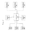
Figure 2 is a schematic block diagram of one embodiment of a control system that may be used in the profiling apparatus of the system illustrated inFigure 1 . -
Figure 3 is an exemplary image obtained by the upper vision system of the embodiment of the profiling apparatus illustrated inFigure 1 . -
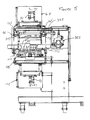
Figures 4 and5 are cross-sectional views of one embodiment of a profiling apparatus that may be used in the systemFigure 1 . -
Figure 6 is a schematic cross-sectional view showing an input stacker. -
Figure 7 is a schematic cross-sectional view showing a product stopper at the inlet to the vision system housing. -
Figure 1 illustrates a product processing system, shown generally at 10, that performs a physical process on a product in which the physical process is dependent on accurate measurement of the profile of the raw product. As shown,product processing system 10 is comprised of aproduct profiling apparatus 15 and aproduct processor 20. Theproduct profiling apparatus 15 functions to measure the profile of the raw product and provide the profile information to theproduct processor 20 that, in turn, uses the information to accurately execute the physical process that is to be performed on the raw product. - In the illustrated embodiment, the acquisition of the product profile information is completed before the particular raw product undergoes physical processing in the
product processor 20. Using the configuration shown inFigure 1 in which theprofiling apparatus 15 is disposed prior to theproduct processor 20, it is possible to acquire complete product profiles for several individual raw products before each of the raw products is provided to the input of theproduct processor 20. Additionally, if theprofiling apparatus 15 is designed as a stand-alone apparatus, then theprofiling apparatus 15 may be used to provide product profile information to a plurality of different product processors that are operating in either a time sequential or concurrent manner. - Generally stated, the
profiling apparatus 15 is comprised of aninput section 25, ascanning section 30, and anoutput section 35. Theinput section 25 includes a plurality ofsupport bars 40 that are disposed to support theproduct 45 that is to be profiled. A plurality ofupstanding fingers 50 extend through interstitial regions between thesupport bars 40. Thefingers 50 engage a rear portion ofproduct 45 and drive it into thescanning section 30. The fingers are arranged to be vertically above the support bars when moved in the driving direction and vertically beneath the bars when conducted in the return direction. -
Scanning section 30 includes ahousing 55 having an input end that is open to receiveproduct 45 and an outlet end that is open to allowproduct 45 to exit therefrom. In the illustrated embodiment,housing 55 comprises aprincipal housing portion 60, an upper vision system housing 65, and a lower vision housing 70. The upper vision system housing 65 includes an upper vision system disposed therein. The upper vision system of the disclosed embodiment includes a vertically directedline laser 75 for illuminating one side of the product in a fixed plane traversed by the driven product and an associatedcamera 80 vertically angled for imaging the laser-illuminated contour of theproduct 45. Similarly, the lower vision system housing 70 includes a lower vision system disposed therein that is comprised of aline laser 85 andcorresponding camera 90 for addressing the other side of the product. Each of the upper and lower vision system housings 65 and 70 includes an opening that is positioned to allow the respective vision system to view aproduct 45 passing through theprincipal housing 60. These openings may merely comprise cut out sections. Preferably, however, the openings are covered with a transparent material to form a window that mechanically isolates the vision system components from the components disposed in theprincipal housing 60 yet does not interfere with the vision system operation. - Although, for purposes of this overview description of the
product profiling apparatus 15, with reference to the early Figures, a single line laser is shown for use in each of the upper and lower vision system housings 65 and 70, it is considered more preferable, as further discussed below with respect to a more detailed discussion of structure and operation of the system machinery, that each of the vision system housings contain two opposing line lasers for illuminating downwardly and across the product from opposed sides of the product. In instances of a considerably uneven profile and/or in the event of highly reflective surface characteristics, opposed sides illumination on the product provides for higher resolution camera imaging. - Within
principal housing 60,product 45 is supported by a plurality ofrounded support bars 95. Thesesupport bars 95 may be formed as extensions ofsupport bars 40, or may be formed as a support component that is distinct fromsupport bars 40. The number and diameter of thesupport bars 95 should be minimized to facilitate accuracy of the scanning measurements provided by the lower vision system. Most preferably, although not shown, the diameters of thesupport bars 95 are substantially reduced to a minimum where they cross the laser light line emanating from the lower vision system laser. -
Product 45 is driven through theprincipal housing 60 by a product drive, shown generally at 100. In the illustrated embodiment, theproduct drive 100 is comprised of aproduct engagement member 105 that is disposed to engage a rear portion ofproduct 45 and drive it alongsupport rods 95 through theprincipal housing 60.Product engagement member 105 includes a plurality of slots that are disposed to allow concurrent operation of thefingers 50 andproduct engagement member 105 at the input end of theprincipal housing 60. A pair ofupstanding members 110 are connected to opposite ends of theproduct engagement member 105. Theupstanding members 110, in turn, are fastened torespective drive belts product engagement member 105 andcorresponding product 45 through theprincipal housing 60. Thedrive belts - At the outlet end of the
principal housing 60, theproduct 45 is engaged by another set offingers 130 that extends through interstitial regions of support bars 95. Support bars 95 may be extended to theoutput section 35 or, alternatively, a further distinct set of support bars may be used to support theproduct 45 at theoutput section 35.Fingers 130 engage the rear portion ofproduct 45 and drive it to theoutput section 35 and therefrom to theprocessing apparatus 20, which, in the disclosed embodiment, is a slicing machine. -
Figure 2 is a schematic block diagram of one embodiment of a control system suitable for controlled operation ofproduct profiling apparatus 15. In the illustrated embodiment, the control system comprises acentral controller 150 that is responsible for 1) controlling the drive mechanisms associated with various portions of theprofiling apparatus 15; 2) coordinating the operation of the vision systems, including acquisition of the profile data; and 3) communicating the profile data to control systems for one ormore product processors 20. To this end, thecentral controller 150 is connected to receive sensed signals from and provide motion control signals to each of the input and output section drives 155 and 160 and the scanning section drive 65. Similarly, thecentral controller 150 is connected to receive sensed signals from and provide scanning control signals to the upper andlower vision systems lower vision systems control system 180 of at least oneproduct processor 20. The profile information may be communicated to thecontrol system 180 in any one of a variety of processing states. For example, thecentral controller 150 may communicate raw profile data to thecontrol system 180. Alternatively, or in addition, thecentral controller 150 may communicate the profile information after the raw data it acquires has been processed at thecentral controller 150 thereby relieving thecontrol system 180 from much of the additional processing overhead associated with profile calculations. - If more than one
product processor 20 is to be served by a singleproduct profiling apparatus 15, then a method for tracking eachproduct 45 through the system to insure that each of theproduct processors 20 receives the correct profile data must be provided. For example, each of theproducts 45 may be provided with a bar-code or other visual image marker that may be acquired or otherwise input to thecentral controller 150 as well as theparticular control system particular product processor 20 that is to slice the particular product. When the identity of theproduct 45 that is to be sliced by the product processor is determined by therespective control system central controller 150. - Operation of the
product profiling apparatus 15 can be described with respect toFigures 1 and2 . First, theproduct 45, shown here as a slab of bacon or the like, is provided atinput section 25 where it is supported bysupport rods 40.Central controller 150 then activates input section drive 155 so thatfingers 50 engage the rear portion ofproduct 45 and drive it into thescanning section 30.Product engagement member 105 is preferably hinged to swing out of the way or otherwise glide over the upper surface ofproduct 45 as it is moved through the opening at the input of thescanning section 30. Thecentral controller 150 been directs the scanning section drive 165 to operate so that theproduct engagement member 105 contacts the rear portion ofproduct 45 and begins to driveproduct 45 through the interior chamber of theprincipal housing 55. Preferably, theproduct 45 is driven a small distance oversupport rods 95 before reaching the position in theprincipal housing 55 in which product scanning begins. This allows the product to settle upon thesupport rods 95 and againstproduct engagement member 105 before scanning thereby increasing the accuracy of the resulting profile data. - In accordance with one embodiment of the
profiling apparatus 15, a resolver or the like associated with thescanning section drive 165 generates control pulses corresponding to incremental movement of theproduct 45 over a fixed distance through theprincipal housing 55. These control pulses are used as synchronization signals that thecentral controller 150 uses to trigger the acquisition of a profile reading. Here, the profile readings are in the form of a visual image captured by thecameras product 45. The product profile is accentuated by directing a line of laser light across the upper and lower surfaces of theproduct 45. Accordingly, the interior of theprincipal housing 55 should be as dark as possible so thatcameras line lasers -
Figure 3 is an exemplary image acquired bycamera 80 ofprofiling apparatus 15. Althoughcamera 80 is capable all of providing an image of 640 X 480 pixels, only a sub-portion of that entire available image is extracted bycentral controller 150 for further processing. As shown, the resulting image is comprised oflinear end regions 200. The linear end regions are formed by reflection of the light fromline laser 75 by a pair of reference reflectors that, preferably, are disposed to be even with the upper surfaces ofsupport rods 95. There are a plurality of elevated, non-linear regions betweenlinear regions 200. These non-linear regions correspond to the upper profile ofproduct 45 that has been illuminated byline laser 75. By taking measurements of the vertical distance (e.g., the number of vertical pixels) betweenlinear end regions 200 and the elevated, non-linear regions, it is possible to calculate the contour of the profile of the product at the position along the interior ofprincipal housing 55 at which the image was acquired. By acquiring a number of such images along the length ofproduct 45, an accurate representation of the upper profile ofproduct 45 can be obtained. Similar images are concurrently acquired bycamera 90 based on illumination of the lower portion ofproduct 45 byline laser 85. As in the case of the upper profile measurements, linear reference regions are formed by reflection of the light fromline laser 85 by a pair of reference reflectors. From the images of the upper and lower product surfaces that are acquired by the upper andlower vision systems central controller 150 can provide a substantially accurate data representation of the complete product profile to controlsystem 180 ofproduct processor 20. - Depending on the content of the
product 45, the laser light impinging on the upper surface ofproduct 45 may be dispersed in different manners. For example, if theproduct 45 is bacon or another fat-containing comestible, fatted regions, such as at 205 disperse the laser light to a greater degree thanlean regions 210. As a result, a broader light band is formed at thefatted regions 205.Controller 150 may compensate for this dispersion by, for example, selecting the area of highest dark pixel concentration for the vertical measurement. Alternatively, a vertical distance measurement may be obtained by taking the average vertical distance of the uppermost vertical distance measurement and the lowermost vertical distance measurement. - As shown in
Figure 3 , the light reflected from the surface ofproduct 45 may be blocked from the view of the camera. These regions appear asvoid regions 215. In such regions,central controller 150 may be programmed to assume a linear transition of the surface contour. Sincevoid regions 215 are generally of a very limited dimension, this assumption still provides for an accurate representation of the overall product profile. Similarly, an assumption that there is a linear transition of the surface contour at the regions of the lower surface ofproduct 45 that are blocked bysupport rods 90 does not significantly diminish the accuracy of the profile measurements. To minimize any inaccuracies introduced by the presence ofsupport rods 95, the number and diameter ofsupport rods 90 should be minimized. Further,support rods 95 should have a generally round cross-section so that they generate obstructed or otherwise unusable regions of the profile image that are substantially equal in the length. - Once
product 45 as been driven to the outlet portion ofscanning section 30, thecentral controller 150 controls the output section drive 160 so thatfingers 130 engage the rear portion ofproduct 45 and drive it from the interior ofscanning section 15 tooutput section 35.Product 45 may be removed by an operator fromsection 35 and provided to the input of asubsequent product processor 20. Alternatively, theoutput section 35 and corresponding output section drive 160 may be designed to driveproduct 45 into a loading position on the subsequent product processor. -
Profiling apparatus 15 may include a digital scale for weighing theproduct 45. The output of the digital scale may be provided tocentral controller 150.Central controller 150 may be programmed to calculate the overall volume ofproduct 45 based on the profile measurements.Central controller 150 may then use the overall product value and the weight provided by the digital scale to calculate the average density of theproduct 45. The average density measurement may be used by a slicing machine, such asproduct processor 20, in combination with the profile measurements to calculate the product slice thicknesses that are required to make a particular weight, such as the weight of product slices that are to be provided in a single consumer package. Alternatively, one or more of the average density, overall volume, or product profile measurements/calculations may be executed by thecontrol system 180 of the slicing machine. -
Figures 4 and5 illustrate a specific embodiment of theprofiling apparatus 15 in which like parts are similarly numbered. Of note in connection with the embodiment shown in these Figures are the drive mechanisms associated withinput section 25, scanningsection 30, andoutput section 30. - It has been found and is considered preferable that, rather than using a single line laser to illuminate a surface of the product as shown in
Figure 4 , a pair of generally opposed lasers applying overlapping beams to cover that surface of the product can yield more profile data and better resolution in the camera image. This would be the case especially in instances where the product surface is quite irregular and/or contains large fatted regions since these situations tend to result in shadowing an/or blurring in the camera image. The more the profile data and the better the resolution in the camera image, the more definite and precise is the surface profile data, there being less need for averaging or extrapolation. - In the case of using more than one line laser in each of the vision system housings above and below the product, the lasers are preferably disposed on opposite sides of the product and projecting their beams down onto and across the product. The camera position generally does not change. In this way, a triangulated approach to capture of the surface profile on both respective sides of the product is utilized.
- As illustrated, the drive mechanisms associated with the
input section 25 andoutput section 30 are interrelated. More particularly, the drive mechanisms are comprised of a single, dual-ended pneumatic actuator, shown generally at 300 that is mounted below support rods 40 (the support rods throughout are continuous and formed as a single set of rods).Actuator 300 includes apiston rod 305 having a first end connected to a firstfinger engagement assembly 315 and a second end connected to a secondfinger engagement assembly 310.Finger engagement assembly 310 includes thefingers 50 thereon whilefinger engagement assembly 315 includes thefingers 130 thereon.Fingers 50 are disposed on apivot rod 320 along with one ormore counterbalance mechanisms 325. Thecounterbalance mechanisms 325urge fingers 50 to rotate about a horizontal axis defined bypivot rod 320 untilfingers 50 engage one ormore stop members 330. The one ormore stop members 330 are disposed to the stock fell rotation offingers 50 when they are in an upright position. This arrangement allowsfingers 50 to slide under asuccessive product 45 disposed on theinput section 25 as the fingers are driven back to the home position after delivering aprevious product 45 to thescanning section 30. - A similar arrangement is provided for
finger assembly 315 disposed at the first end ofpiston rod 305. Here, however, the one ormore counterbalance mechanisms 335 of thefinger assembly 315 are positioned to engage afurther stop member 340 at the output position of theoutput section 35. As thefingers 130drive product 45 alongoutput section 35,counterbalance mechanisms 335 are driven into engagement with thefurther stop mechanisms 340. This causes thefingers 130 to rotate about a horizontal axis defined bypivot rod 345 which assists in driving theproduct 45 fromoutput section 35 to, for example, the input of a slicing machine. - In the embodiment shown in
Figures 4 and5 , the scanning section drive includesmotor 350 that is connected to rotatedrive roller 355. Driveroller 355, in turn, drivesbelts drive roller 355 andidle roller 360.Securement mechanisms 365 are connected to upstanding members 110 (shown inFigure 5 ) to secureupstanding members 110 andproduct engagement member 105 withdrives belts securement mechanisms 365 are connected to one another by astrut 372 to enhance the rigidity of the overall drive mechanism. Additionally,securement mechanisms 365 each engagerespective guide rods 377 that extend along the length of the transport path along which theproduct engagement member 105 movesproduct 45 throughscanning section 30. Preferably,securement members 365 each include a pivoted connection 378 that allows theproduct engagement member 105 to glide over the upper surface of aproduct 45 disposed in thescanning section 30 asmember 105 is returned to its home position after driving a product from thescanning section 30. Alternatively, theproduct engagement member 105 may be actively moved by, for example, an actuator, so that its movement to the home position is not obstructed by theproduct 45. - To further facilitate and enhance continuous, automated running of the invention product processing system, the product is preferably supplied to the
input section 25 from a stacked input.Figure 6 illustrates a specific embodiment of a vertically extendingstacker 400, in the form of a chute the walls of which are defined by columns ofrollers 410. The lower end of the chute is immediately above, and opens onto, theinput section 25. The upper end of the chute extends above and angles away from the input section. The chute defines a gravity-drop passage in which a plurality of the products can be stacked one on top of the other for successive and automatic loading onto theinput section 25. After each previous, underlying product has landed on the input section support bars and been passed from beneath the chute into thescanning section 30 by thefingers 50, the next product in the stack drops onto the input section support bars such that the system is automatically loaded for a continuous running operation. - As a back-up precaution in the event the
scanning section drive 350 gets ahead of the return movement of thefingers 130, there is preferably provided aproduct stop 380, shown inFigure 7 , which could hold the movement of the product under the influence of theengagement member 105 until thefingers 130 have fully returned to engage the next product. Theproduct stopper 380 is freely pivotable about a transverse, horizontal axis, and formed at a forward side with an L-shapedstop wall 381 and on the other side of the pivot axis with acounterweight abutment 382. Until the piston carrying thefingers 130 is fully returned, the L-shapedstop wall 381 is in a raised blocking position in the path of conveyance of the next product being delivered to the vision system housing, as shown by the dotted line image inFigure 7 . With the piston in its fully-returned position, thecounterweight abutment 382 is engaged and raised, causing thestop wall 381 to be lowered and not obstructing the conveyance movement of the next product. In this case, theengagement member 105 is able to conduct the product over the tilted-downfingers 130, as well as the lowered stop wall, and fully into the vision system housing for further conveyance, from behind, by the then raisedfingers 130. - Other features of the specific embodiment that are shown in
Figures 4 and5 includereference reflectors 375. Thereference reflectors 375 are those referenced above in connection with the operation of theprofiling apparatus 15. - Numerous modifications may be made to the foregoing system without departing from the basic teachings thereof. Although the present invention has been described in substantial detail with reference to one or more specific embodiments, those of skill in the art will recognize that changes may be made thereto without departing from the scope and spirit of the invention as set forth herein.
Claims (25)
- An apparatus (15) for acquiring a profile of a food product (45) for use in subsequent processing of the food product (45) comprising:a) a scanning chamber (55) for accepting the product (45), the scanning chamber having an open input end to receive the product and an open outlet end to allow product to exit the housing, and a first vision system opening and a second vision system opening;b) one or more product drives (100, 115, 120) that are operable to drive the product (45) through the scanning chamber (55);c) a first vision system (170) disposed to acquire visual information relating to a first side of a profile of the product (45) and comprising at least one first line laser arranged to project a first line on the first side of the profile of the product and a first camera for imaging the first line, the first camera being located outside the scanning chamber and imaging the first line through the first vision system opening;d) a second vision system (175) disposed to acquire visual information relating to the profile of a second side of the product (45) the second side being opposite to the first side across a thickness of the product and comprising at least one second line laser arranged to project a second line on the second side of the profile of the product and a second camera for imaging the second line, the second camera being located outside the scanning chamber and imaging the second line through the second vision system opening;e) a control system (150) connected for control of the first and second vision systems and operating to convert the information received from the first and second vision systems (170, 175) into a format suitable for use by a subsequent product processor (20).
- The apparatus (15) than 1, wherein the first laser comprises at least one upper laser (75) and an upper camera (80) located above the product (45) and the second laser comprises at least one lower laser (85) and a lower camera (90) located below the product (45) in the scanning chamber (55).
- The apparatus (15) of claim 2, wherein the product drives (100) conduct the product (45) in a horizontal direction through the scanning chamber (55).
- The apparatus (15) of any of claims 1 to 3, wherein the first camera comprises an upper camera (80) and the second camera comprises a lower camera (90), the systems being adapted to generate visual information relating to the profiles of the upper portion and lower portions of the product (45) comprising multiple images acquire by the cameras (80, 90) at fixed increment along the length of the product (45).
- The apparatus (15) of any of claims 1 to 4, wherein the at least one first laser comprises at least two upper lasers (75) disposed on opposite sides of the scanning path and an upper camera (180) located above the scanning path, and the at least one second laser comprises at least two lower lasers (85) disposed on opposite sides of the scanning path and a lower camera (90) located below the scanning path.
- The apparatus (15) of any of claims 1 to 5, wherein the product drives comprise a scanning section drive (105) for moving the product (45) through the scanning chamber (55), which scanning section drive (105) is independent of a subsequent product processor (20).
- The apparatus (15) of any of claims 1 to 6, wherein the product drives comprise a scanning section drive (105), for moving the product (45) through the scanning chamber (55) an output section drive (130), for delivery the product (45) out of the scanning chamber (55).
- The apparatus (15) of claim 7 including an input section drive (50) for moving the product (45) to be engaged by the scanning section drive (105).
- The apparatus (15) of claim 7 or claim 8, wherein the output section drive (130) is deployed to deliver the product (45) into a loading position on the subsequent product processor (20).
- The apparatus (15) of any of claims 1 to 9, wherein the scanning chamber (55) has reference reflectors for disposition on opposed sides of the product (45), and wherein the cameras (80, 90) acquire multiple visual images of the surface profile appearing as linear end regions corresponding to the reference reflectors and a plurality of vertically offset, non linear regions between the end regions corresponding to the upper and lower surface profiles of the product (45).
- The apparatus (15) of any of claims 1 to 10, wherein the product drives comprise an input section and includes a stacker (400) having a chute holding a plurality of products (45) in a stacked orientation arranged above the input section, and a dispensing mechanism for depositing the products (45) sequentially onto the input section.
- The apparatus (15) of any of claims 1 to 11, wherein the product (45) comprises meat slabs and the subsequent product processor (20) comprises a slicing apparatus.
- The apparatus (15) of any of claims 1 to 12, wherein the subsequent product processor (20) comprises a plurality of processors (180) and the one product drive conducts a product to each processor.
- The apparatus (15) of any of the preceding claims, wherein a controller (150) is connected to the first and second vision systems (170, 175) and adapted to convert information received from the upper and lower vision systems (170, 175) into a format suitable for subsequent use by a product processor (20).
- The apparatus of any of the preceding claims, wherein at least one of the first and second vision systems comprises plural lasers for projecting overlapping lines on the respective side of the product.
- The apparatus of any of the preceding claims, wherein at least one of the first vision system opening and a second vision system opening are covered by a transparent material to mechanically isolate the respective first camera or the second camera from the scanning chamber.
- The apparatus of any of the preceding claims, wherein the scanning chamber is substantially enclosed to be dark for imaging the first and second lines.
- An apparatus (15) for acquiring a profile of a food product (45) for use in subsequent processing of the food product (45) comprising:a first vision system (170) disposed to acquire visual information relating to a first side of a profile of the product (45) and comprising at least two first line lasers arranged to project an overlapping first line on the first side of the profile of the product and a first camera for imaging the first line; anda control system (150) connected for control of the first system and operating to convert the information received from the first vision system (170) into a format suitable for use by a subsequent product processor (20).
- The apparatus (15) than 18, further comprising a second vision system (175) disposed to acquire visual information relating to the profile of a second side of the product (45) the second side being opposite to the first side across a thickness of the product and comprising at least one second line laser (85) arranged to project a second line on the second side of the profile of the product and a second camera for imaging the second line.
- The apparatus (15) of claim 19, comprising a scanning chamber (55) for accepting the product (45), the scanning chamber having an open input end to receive the product and an open outlet end to allow product to exit the housing, and a first vision system opening and a second vision system opening, the first and second cameras arranged to image a product within the chamber through the first and second vision system openings respectively; and
one or more product drives (100, 115, 120) that are operable to drive the product (45) through the scanning chamber (55); wherein the product drives (100) conduct the product (45) in a horizontal direction through the scanning chamber (55). - The apparatus (15) of any of claims 19 to 20, wherein the first camera comprises an upper camera (80) and the second camera comprises a lower camera (90), the systems being adapted to generate visual information relating to the profiles of the upper portion and lower portions of the product (45) comprising multiple images acquire by the cameras (80, 90) at fixed increment along the length of the product (45).
- The apparatus (15) of any of claims 18 to 21, wherein the at least two first lasers are (75) disposed on opposite sides of the scanning path and the first camera is an upper camera (180) located above the scanning path, and the at least one second laser comprises at least two lower lasers (85) disposed on opposite sides of the scanning path and the second camera (90) is located below the scanning path.
- The apparatus (15) of any of claims 20 to 21, wherein the product drives comprise a scanning section drive (105) for moving the product (45) through the scanning chamber (55), which scanning section drive (105) is independent of a subsequent product processor (20).
- The apparatus (15) of any of claims 20-22, wherein the product drives comprise a scanning section drive (105), for moving the product (45) through the scanning chamber (55) an output section drive (130), for delivery the product (45) out of the scanning chamber (55).
- The apparatus (15) of any of claims 18 to 24, wherein the product (45) comprises meat slabs and the subsequent product processor (20) comprises a slicing apparatus.
Applications Claiming Priority (3)
| Application Number | Priority Date | Filing Date | Title |
|---|---|---|---|
| US13020899P | 1999-04-20 | 1999-04-20 | |
| EP07004190.0A EP1782929B2 (en) | 1999-04-20 | 2000-04-20 | Automated product profiling apparatus |
| EP00928257A EP1178878B2 (en) | 1999-04-20 | 2000-04-20 | Automated product profiling apparatus |
Related Parent Applications (3)
| Application Number | Title | Priority Date | Filing Date |
|---|---|---|---|
| EP00928257.5 Division | 2000-04-20 | ||
| EP07004190.0A Division-Into EP1782929B2 (en) | 1999-04-20 | 2000-04-20 | Automated product profiling apparatus |
| EP07004190.0 Division | 2007-02-28 |
Publications (2)
| Publication Number | Publication Date |
|---|---|
| EP2266766A2 true EP2266766A2 (en) | 2010-12-29 |
| EP2266766A3 EP2266766A3 (en) | 2012-03-07 |
Family
ID=22443578
Family Applications (3)
| Application Number | Title | Priority Date | Filing Date |
|---|---|---|---|
| EP10012278A Withdrawn EP2266766A3 (en) | 1999-04-20 | 2000-04-20 | Automated product profiling apparatus |
| EP00928257A Expired - Lifetime EP1178878B2 (en) | 1999-04-20 | 2000-04-20 | Automated product profiling apparatus |
| EP07004190.0A Expired - Lifetime EP1782929B2 (en) | 1999-04-20 | 2000-04-20 | Automated product profiling apparatus |
Family Applications After (2)
| Application Number | Title | Priority Date | Filing Date |
|---|---|---|---|
| EP00928257A Expired - Lifetime EP1178878B2 (en) | 1999-04-20 | 2000-04-20 | Automated product profiling apparatus |
| EP07004190.0A Expired - Lifetime EP1782929B2 (en) | 1999-04-20 | 2000-04-20 | Automated product profiling apparatus |
Country Status (7)
| Country | Link |
|---|---|
| EP (3) | EP2266766A3 (en) |
| AT (1) | ATE359156T1 (en) |
| AU (1) | AU4651800A (en) |
| DE (3) | DE20023774U1 (en) |
| DK (1) | DK1782929T3 (en) |
| NO (1) | NO20015117L (en) |
| WO (1) | WO2000062983A1 (en) |
Cited By (3)
| Publication number | Priority date | Publication date | Assignee | Title |
|---|---|---|---|---|
| WO2020126631A1 (en) | 2018-12-19 | 2020-06-25 | 6D Systems | Facility and method for the automated processing, and in particular the slicing, of a rigid product such as a frozen food product |
| FR3090442A1 (en) | 2018-12-19 | 2020-06-26 | 6D Systems | ROBOT GRIPPER |
| FR3090444A1 (en) | 2018-12-19 | 2020-06-26 | 6D Systems | INSTALLATION AND METHOD FOR AUTOMATED PROCESSING, AND PARTICULARLY SLICING, OF A RIGID PRODUCT SUCH AS A FROZEN FOOD PRODUCT |
Families Citing this family (33)
| Publication number | Priority date | Publication date | Assignee | Title |
|---|---|---|---|---|
| US6997089B2 (en) | 2002-06-25 | 2006-02-14 | Formax, Inc. | Optical grading system for slicer apparatus |
| US7055419B2 (en) | 2003-01-10 | 2006-06-06 | Formax, Inc. | System and method for optimizing slices from slicing apparatus |
| DE102004010900A1 (en) * | 2004-03-05 | 2005-09-22 | Alpma Alpenland Maschinenbau Gmbh | Apparatus and method for cutting food products |
| GB0512877D0 (en) * | 2005-06-24 | 2005-08-03 | Aew Delford Group Ltd | Improved vision system |
| GB2427913B (en) * | 2005-06-24 | 2008-04-02 | Aew Delford Systems Ltd | Two colour vision system |
| DE102005047752B3 (en) * | 2005-09-28 | 2006-10-05 | Nordischer Maschinenbau Rud. Baader Gmbh + Co Kg | Trimming machine for fish fillets has conveyor which continuously feeds fillets to trimming head and camera which detects position of each fillet and controls head so that it automatically trims its surface |
| GB0612246D0 (en) * | 2006-06-21 | 2006-08-02 | Aew Delford Systems | Vision system using strobed illumination |
| GB2446566B (en) * | 2007-02-15 | 2009-01-07 | Aew Delford Systems Ltd | Control of food slicing machines |
| US7860277B2 (en) | 2007-04-10 | 2010-12-28 | Bizerba Gmbh & Co. Kg | Food product checking system and method for identifying and grading food products |
| DE102007021510A1 (en) * | 2007-05-04 | 2008-11-06 | Maja-Maschinenfabrik Hermann Schill Gmbh & Co. Kg | Article e.g. meat, cutting device for use in food industry, has hand-hold device-drive moving upward or downward around hold-down device in straight line to increase or decrease integrity of conveying unit |
| DE102009023728B4 (en) * | 2009-06-03 | 2017-02-02 | Weber Maschinenbau Gmbh Breidenbach | Apparatus and method for slicing food products |
| DE102009036682A1 (en) | 2009-08-07 | 2011-02-17 | Weber Maschinenbau Gmbh Breidenbach | Slicing food products |
| IT1395814B1 (en) | 2009-10-12 | 2012-10-26 | Gallucci | APPARATUS FOR CUTTING AND / OR ENGRAVING ITEMS INCLUDING A FLAT SURFACE ON WHICH DRAWINGS AND / OR WRITINGS ARE REPRODUCED AND METHOD TO IMPLEMENT THE APPARATUS |
| DE102009059855A1 (en) | 2009-12-21 | 2011-06-22 | Weber Maschinenbau GmbH, 35236 | scanning |
| EP2664425A3 (en) * | 2009-12-23 | 2014-10-22 | CFS Bühl GmbH | Method for classifying the quality of food slices of a stick of food |
| DE102010021951A1 (en) | 2010-05-28 | 2011-12-01 | Weber Maschinenbau Gmbh Breidenbach | Scanning device for determining partial cross-sectional profiles of meat product that is cut by heavy-duty slicer, has detection device detecting images containing light lines, where scanning planes and lines are separated from each other |
| EP2420362B1 (en) | 2010-08-18 | 2015-04-15 | Weber Maschinenbau GmbH Breidenbach | Method and device for cutting food products |
| DE102010034677A1 (en) | 2010-08-18 | 2012-02-23 | Weber Maschinenbau Gmbh Breidenbach | Portionskomplettierung when mehrspuringen slicing |
| DE102010034674A1 (en) | 2010-08-18 | 2012-02-23 | Weber Maschinenbau Gmbh Breidenbach | Simultaneous slicing of multi-track food products |
| DE102010049310A1 (en) | 2010-10-22 | 2012-04-26 | Weber Maschinenbau Gmbh Breidenbach | Scanning device and method for determining the contour of an object |
| NL2006958C2 (en) | 2011-06-17 | 2012-12-18 | Marel Townsend Further Proc Bv | Processing a mass of pumpable foodstuff material. |
| DE102012102649A1 (en) * | 2012-03-27 | 2013-10-02 | Uwe Reifenhäuser | Method and device for weight-accurate cutting of a food strand |
| CN102729289B (en) * | 2012-06-27 | 2015-07-22 | 济南好为尔机械有限公司 | Food weight-fixed cutting method and food cutting machine |
| DE102012223140A1 (en) * | 2012-12-05 | 2014-06-05 | Weber Maschinenbau Gmbh Breidenbach | Method and device for examining a food product to be pelleted in a pelleting operation |
| DE102014103221A1 (en) * | 2014-03-11 | 2015-09-17 | Alpma Alpenland Maschinenbau Gmbh | Arrangement of optical elements for inspection of food surfaces |
| DE102016101753A1 (en) | 2016-02-01 | 2017-08-03 | Textor Maschinenbau GmbH | CUTTING FOOD PRODUCTS |
| DE102016102034A1 (en) | 2016-02-05 | 2017-08-10 | Textor Maschinenbau GmbH | Slicing food products |
| EP3500410B1 (en) | 2016-08-18 | 2022-09-14 | GEA Food Solutions Germany GmbH | Method for slicing foodstuff into portions of precise weight |
| CN106690335B (en) * | 2017-02-21 | 2019-01-01 | 山东交通学院 | A kind of freestone class peach seeder |
| IT201700076239A1 (en) | 2017-07-06 | 2019-01-06 | Grasselli S P A | Food scanning equipment. |
| CN108908464B (en) * | 2018-06-27 | 2020-09-18 | 中国地质大学(北京) | Rapid width measuring device for medium plate production based on computer technology |
| EP3952657A4 (en) | 2019-04-08 | 2023-04-19 | Provisur Technologies, Inc. | Apparatus and method for cutting meat products into blocks of meat |
| GB2586437B (en) * | 2019-05-03 | 2022-09-07 | Thurne Middleby Ltd | Feeding of food products in slicing or portioning machines |
Family Cites Families (33)
| Publication number | Priority date | Publication date | Assignee | Title |
|---|---|---|---|---|
| US4158507A (en) † | 1977-07-27 | 1979-06-19 | Recognition Equipment Incorporated | Laser measuring system for inspection |
| US4188544A (en) † | 1977-08-22 | 1980-02-12 | Weyerhaeuser Company | Method and apparatus for automatically processing a workpiece employing calibrated scanning |
| US4264208A (en) † | 1978-10-25 | 1981-04-28 | Semperit Aktiengesellschaft | Method and apparatus for measuring the surface of an object |
| US4541722A (en) * | 1982-12-13 | 1985-09-17 | Jenksystems, Inc. | Contour line scanner |
| GB8330422D0 (en) * | 1983-11-15 | 1983-12-21 | Whitehouse J A | Sizing apparatus |
| US4557019A (en) * | 1984-08-10 | 1985-12-10 | Seafreeze Limited Partnership | Automatic portion-cutting method and machine |
| DK157380C (en) † | 1986-11-06 | 1991-08-12 | Lumetech As | METHODS OF OPTICAL, BODY-FREE MEASUREMENT OF MEAT TEXTURE |
| US4718146A (en) * | 1987-01-20 | 1988-01-12 | Oscar Mayer Foods Corporation | Apparatus for sawing turkey breasts and other objects |
| CA1323290C (en) * | 1988-09-14 | 1993-10-19 | Aaron U. Jones | Method and apparatus for an automatic sawmill |
| US5249491A (en) * | 1987-08-21 | 1993-10-05 | Aaron U. Jones | Sawmill method and apparatus with movable scanning means |
| JP2563390B2 (en) † | 1987-11-17 | 1996-12-11 | マルハ 株式会社 | Cutting equipment for food processing |
| DE3805455A1 (en) † | 1988-02-22 | 1989-08-31 | Linck Masch Gatterlinck | Device for the photoelectric scanning and/or measurement of wood products |
| FR2627423A1 (en) * | 1988-02-23 | 1989-08-25 | Cerisy Sa | Controlled food slicing machine - uses video image of slice to allow automatic determination of thickness |
| DE3808790A1 (en) * | 1988-03-16 | 1989-09-28 | Guenther Weber | METHOD FOR OBTAINING WEIGHT-CONSTANT PORTIONS OR DISCS FROM SLICED FOOD PRODUCTS |
| US4875254A (en) * | 1988-03-22 | 1989-10-24 | Design Systems, Inc. | Method and apparatus for automatically cutting food products to predetermined weight or shape |
| US4907294A (en) * | 1988-04-28 | 1990-03-06 | U.S. Natural Resources, Inc. | Log scanning system |
| US5028799A (en) * | 1988-08-01 | 1991-07-02 | Robotic Vision System, Inc. | Method and apparatus for three dimensional object surface determination using co-planar data from multiple sensors |
| DE3836859C2 (en) * | 1988-12-15 | 1998-04-09 | Kuchler Fritz | Slicer |
| CA2070822A1 (en) † | 1989-12-05 | 1991-06-06 | Herbert Barg | Process and arrangement for optoelectronic measuring of objects |
| GB9006804D0 (en) * | 1990-03-27 | 1990-05-23 | Thurne Eng Co Ltd | Slicing machine |
| FR2663877B1 (en) * | 1990-06-29 | 1995-01-13 | Soviba Viandes Bretagne Anjou | AUTOMATIC MACHINE FOR SLICING NON RIGID PRODUCTS SUCH AS FOOD MATERIALS SUCH AS MEAT. |
| DE4037383A1 (en) * | 1990-11-20 | 1992-05-21 | Mesacon Messtechnik | METHOD FOR CONTINUOUS TOUCH-FREE MEASUREMENT OF PROFILES AND DEVICE FOR CARRYING OUT THE MEASURING METHOD |
| DE69100654T2 (en) * | 1991-03-22 | 1994-03-10 | Frisco Findus Ag | Cutting method and apparatus. |
| FR2678201B1 (en) * | 1991-06-25 | 1996-02-16 | Royal Champignon Sa | AUTOMATIC CUTTING PLANT FOR MUSHROOM FEET |
| GB9127139D0 (en) † | 1991-12-20 | 1992-02-19 | 3D Scanners Ltd | Scanning unit |
| DK69992D0 (en) * | 1992-05-26 | 1992-05-26 | Northern Food Line Machines K | MACHINE FOR PORTION CUTTING OF ISAER FOODSTUFFS |
| US5352153A (en) * | 1993-07-13 | 1994-10-04 | The Laitram Corporation | Imaging system for use in processing transversely cut fish body sections |
| JP3523310B2 (en) † | 1993-12-27 | 2004-04-26 | 株式会社エフ・エフ・シー | Automatic cutting device for fish meat |
| DK170845B1 (en) * | 1994-02-01 | 1996-02-05 | Slagteriernes Forskningsinst | Installation, apparatus and method for on-line determination of quality characteristics of pieces of meat |
| DE19604254B4 (en) * | 1996-02-06 | 2006-11-23 | Weber Maschinenbau Gmbh & Co. Kg | Method and device for obtaining weight-constant portions or slices from cut-up food products |
| CA2200545C (en) * | 1997-03-20 | 2003-01-07 | Didier Conte | Apparatus and method for removing ribs |
| GB9805445D0 (en) * | 1998-03-16 | 1998-05-13 | Whitehouse John A | Product scanner |
| US6100540A (en) * | 1999-02-22 | 2000-08-08 | Visidyne, Inc. | Laser displacement measurement system |
-
2000
- 2000-04-20 EP EP10012278A patent/EP2266766A3/en not_active Withdrawn
- 2000-04-20 EP EP00928257A patent/EP1178878B2/en not_active Expired - Lifetime
- 2000-04-20 AU AU46518/00A patent/AU4651800A/en not_active Abandoned
- 2000-04-20 DE DE20023774U patent/DE20023774U1/en not_active Expired - Lifetime
- 2000-04-20 WO PCT/US2000/010691 patent/WO2000062983A1/en active IP Right Grant
- 2000-04-20 DK DK07004190.0T patent/DK1782929T3/en active
- 2000-04-20 AT AT00928257T patent/ATE359156T1/en not_active IP Right Cessation
- 2000-04-20 DE DE60034332T patent/DE60034332T3/en not_active Expired - Lifetime
- 2000-04-20 EP EP07004190.0A patent/EP1782929B2/en not_active Expired - Lifetime
- 2000-04-20 DE DE00928257T patent/DE00928257T1/en active Pending
-
2001
- 2001-10-19 NO NO20015117A patent/NO20015117L/en not_active Application Discontinuation
Non-Patent Citations (1)
| Title |
|---|
| None |
Cited By (3)
| Publication number | Priority date | Publication date | Assignee | Title |
|---|---|---|---|---|
| WO2020126631A1 (en) | 2018-12-19 | 2020-06-25 | 6D Systems | Facility and method for the automated processing, and in particular the slicing, of a rigid product such as a frozen food product |
| FR3090442A1 (en) | 2018-12-19 | 2020-06-26 | 6D Systems | ROBOT GRIPPER |
| FR3090444A1 (en) | 2018-12-19 | 2020-06-26 | 6D Systems | INSTALLATION AND METHOD FOR AUTOMATED PROCESSING, AND PARTICULARLY SLICING, OF A RIGID PRODUCT SUCH AS A FROZEN FOOD PRODUCT |
Also Published As
| Publication number | Publication date |
|---|---|
| DE20023774U1 (en) | 2006-05-18 |
| ATE359156T1 (en) | 2007-05-15 |
| WO2000062983A1 (en) | 2000-10-26 |
| EP1782929B2 (en) | 2019-12-25 |
| DE60034332T2 (en) | 2007-12-20 |
| EP1178878B1 (en) | 2007-04-11 |
| DE60034332T3 (en) | 2012-02-09 |
| NO20015117D0 (en) | 2001-10-19 |
| DE00928257T1 (en) | 2005-12-15 |
| DE60034332D1 (en) | 2007-05-24 |
| DK1782929T3 (en) | 2013-04-15 |
| EP1178878A1 (en) | 2002-02-13 |
| EP1782929A3 (en) | 2008-12-17 |
| EP1782929A2 (en) | 2007-05-09 |
| EP1178878B2 (en) | 2011-05-04 |
| AU4651800A (en) | 2000-11-02 |
| EP2266766A3 (en) | 2012-03-07 |
| EP1782929B1 (en) | 2013-01-02 |
| NO20015117L (en) | 2001-12-19 |
| EP1178878A4 (en) | 2005-11-16 |
Similar Documents
| Publication | Publication Date | Title |
|---|---|---|
| US7450247B2 (en) | Automated product profiling apparatus and product slicing system using same | |
| EP1782929B1 (en) | Automated product profiling apparatus | |
| US9888696B2 (en) | Automated product profiling apparatus and product slicing system using the same | |
| US5054345A (en) | Method of obtaining constant weight portions or slices of sliced food products | |
| US5481466A (en) | Meat slicing machine and method of use thereof | |
| US7373217B2 (en) | Apparatus for slicing a food product and method therefore | |
| EP0713753B1 (en) | Slicing machine for slicing two or more food loaves | |
| AU2005213846B2 (en) | Method and apparatus for portion cutting of food products or similar items | |
| US5129298A (en) | Automatic machine for slicing non-rigid products, such as foodstuffs such as meats | |
| US20120198974A1 (en) | Method for obtaining constant weight slices from sliced food products and device for performing said method | |
| DK2187752T3 (en) | DEVICE AND PROCEDURE FOR SEPARATING SEPARATELY | |
| WO2006136814A1 (en) | Vision system with picture correction storage | |
| JP2002542046A (en) | Method and apparatus for separating a plurality of sliced objects from an original object | |
| EP1583427B1 (en) | A method of processing fillets, such as salmon fillets, and a system for performing the method | |
| US20220153531A1 (en) | Method for positioning an article to be transported and device for carrying out the method |
Legal Events
| Date | Code | Title | Description |
|---|---|---|---|
| PUAI | Public reference made under article 153(3) epc to a published international application that has entered the european phase |
Free format text: ORIGINAL CODE: 0009012 |
|
| 17P | Request for examination filed |
Effective date: 20100930 |
|
| AC | Divisional application: reference to earlier application |
Ref document number: 1782929 Country of ref document: EP Kind code of ref document: P Ref document number: 1178878 Country of ref document: EP Kind code of ref document: P |
|
| AK | Designated contracting states |
Kind code of ref document: A2 Designated state(s): AT BE CH CY DE DK ES FI FR GB GR IE IT LI LU MC NL PT SE |
|
| RIN1 | Information on inventor provided before grant (corrected) |
Inventor name: LINDEE, SCOTT A. Inventor name: SANDBERG, GLEN Inventor name: BANIA, ROBERT Inventor name: SALVATORE, LAMARTINO |
|
| PUAL | Search report despatched |
Free format text: ORIGINAL CODE: 0009013 |
|
| AK | Designated contracting states |
Kind code of ref document: A3 Designated state(s): AT BE CH CY DE DK ES FI FR GB GR IE IT LI LU MC NL PT SE |
|
| RIC1 | Information provided on ipc code assigned before grant |
Ipc: B26D 7/00 20060101ALI20120131BHEP Ipc: B26D 5/00 20060101AFI20120131BHEP |
|
| 17Q | First examination report despatched |
Effective date: 20121206 |
|
| RAP1 | Party data changed (applicant data changed or rights of an application transferred) |
Owner name: FORMAX, INC. |
|
| STAA | Information on the status of an ep patent application or granted ep patent |
Free format text: STATUS: EXAMINATION IS IN PROGRESS |
|
| STAA | Information on the status of an ep patent application or granted ep patent |
Free format text: STATUS: THE APPLICATION IS DEEMED TO BE WITHDRAWN |
|
| 18D | Application deemed to be withdrawn |
Effective date: 20170830 |