EP2261619A2 - Infrared thermometer and probe cover thereof - Google Patents
Infrared thermometer and probe cover thereof Download PDFInfo
- Publication number
- EP2261619A2 EP2261619A2 EP10184378A EP10184378A EP2261619A2 EP 2261619 A2 EP2261619 A2 EP 2261619A2 EP 10184378 A EP10184378 A EP 10184378A EP 10184378 A EP10184378 A EP 10184378A EP 2261619 A2 EP2261619 A2 EP 2261619A2
- Authority
- EP
- European Patent Office
- Prior art keywords
- probe
- temperature
- tip
- sensor
- thermometer
- Prior art date
- Legal status (The legal status is an assumption and is not a legal conclusion. Google has not performed a legal analysis and makes no representation as to the accuracy of the status listed.)
- Withdrawn
Links
- 239000000523 sample Substances 0.000 title claims abstract description 132
- 239000000463 material Substances 0.000 claims description 6
- 125000006850 spacer group Chemical group 0.000 claims description 3
- 229910052751 metal Inorganic materials 0.000 description 21
- 239000002184 metal Substances 0.000 description 21
- 230000005855 radiation Effects 0.000 description 16
- 239000010408 film Substances 0.000 description 9
- 210000000214 mouth Anatomy 0.000 description 9
- 230000036760 body temperature Effects 0.000 description 7
- 238000009529 body temperature measurement Methods 0.000 description 5
- 238000000034 method Methods 0.000 description 5
- 229910052782 aluminium Inorganic materials 0.000 description 3
- XAGFODPZIPBFFR-UHFFFAOYSA-N aluminium Chemical compound [Al] XAGFODPZIPBFFR-UHFFFAOYSA-N 0.000 description 3
- 239000011521 glass Substances 0.000 description 3
- 238000010438 heat treatment Methods 0.000 description 3
- 230000005676 thermoelectric effect Effects 0.000 description 3
- 238000004364 calculation method Methods 0.000 description 2
- 238000004891 communication Methods 0.000 description 2
- 238000011109 contamination Methods 0.000 description 2
- PCHJSUWPFVWCPO-UHFFFAOYSA-N gold Chemical compound [Au] PCHJSUWPFVWCPO-UHFFFAOYSA-N 0.000 description 2
- 239000010931 gold Substances 0.000 description 2
- 229910052737 gold Inorganic materials 0.000 description 2
- 229920001903 high density polyethylene Polymers 0.000 description 2
- 239000004700 high-density polyethylene Substances 0.000 description 2
- 238000003780 insertion Methods 0.000 description 2
- 230000037431 insertion Effects 0.000 description 2
- 229920001684 low density polyethylene Polymers 0.000 description 2
- 239000004702 low-density polyethylene Substances 0.000 description 2
- 238000005259 measurement Methods 0.000 description 2
- 229920003023 plastic Polymers 0.000 description 2
- 239000004033 plastic Substances 0.000 description 2
- 210000000664 rectum Anatomy 0.000 description 2
- 238000012546 transfer Methods 0.000 description 2
- 229910001369 Brass Inorganic materials 0.000 description 1
- RYGMFSIKBFXOCR-UHFFFAOYSA-N Copper Chemical compound [Cu] RYGMFSIKBFXOCR-UHFFFAOYSA-N 0.000 description 1
- 210000001099 axilla Anatomy 0.000 description 1
- 239000010951 brass Substances 0.000 description 1
- 238000010276 construction Methods 0.000 description 1
- 229910052802 copper Inorganic materials 0.000 description 1
- 239000010949 copper Substances 0.000 description 1
- 239000013039 cover film Substances 0.000 description 1
- 230000000994 depressogenic effect Effects 0.000 description 1
- 239000007789 gas Substances 0.000 description 1
- 239000007788 liquid Substances 0.000 description 1
- 229910052755 nonmetal Inorganic materials 0.000 description 1
- 150000002843 nonmetals Chemical class 0.000 description 1
- 238000002360 preparation method Methods 0.000 description 1
- 238000002310 reflectometry Methods 0.000 description 1
- 210000003296 saliva Anatomy 0.000 description 1
- 239000007787 solid Substances 0.000 description 1
- 238000001228 spectrum Methods 0.000 description 1
- 230000000007 visual effect Effects 0.000 description 1
Images


Classifications
-
- G—PHYSICS
- G01—MEASURING; TESTING
- G01J—MEASUREMENT OF INTENSITY, VELOCITY, SPECTRAL CONTENT, POLARISATION, PHASE OR PULSE CHARACTERISTICS OF INFRARED, VISIBLE OR ULTRAVIOLET LIGHT; COLORIMETRY; RADIATION PYROMETRY
- G01J5/00—Radiation pyrometry, e.g. infrared or optical thermometry
- G01J5/02—Constructional details
-
- G—PHYSICS
- G01—MEASURING; TESTING
- G01J—MEASUREMENT OF INTENSITY, VELOCITY, SPECTRAL CONTENT, POLARISATION, PHASE OR PULSE CHARACTERISTICS OF INFRARED, VISIBLE OR ULTRAVIOLET LIGHT; COLORIMETRY; RADIATION PYROMETRY
- G01J5/00—Radiation pyrometry, e.g. infrared or optical thermometry
- G01J5/0022—Radiation pyrometry, e.g. infrared or optical thermometry for sensing the radiation of moving bodies
- G01J5/0025—Living bodies
-
- G—PHYSICS
- G01—MEASURING; TESTING
- G01J—MEASUREMENT OF INTENSITY, VELOCITY, SPECTRAL CONTENT, POLARISATION, PHASE OR PULSE CHARACTERISTICS OF INFRARED, VISIBLE OR ULTRAVIOLET LIGHT; COLORIMETRY; RADIATION PYROMETRY
- G01J5/00—Radiation pyrometry, e.g. infrared or optical thermometry
- G01J5/02—Constructional details
- G01J5/021—Probe covers for thermometers, e.g. tympanic thermometers; Containers for probe covers; Disposable probes
-
- G—PHYSICS
- G01—MEASURING; TESTING
- G01J—MEASUREMENT OF INTENSITY, VELOCITY, SPECTRAL CONTENT, POLARISATION, PHASE OR PULSE CHARACTERISTICS OF INFRARED, VISIBLE OR ULTRAVIOLET LIGHT; COLORIMETRY; RADIATION PYROMETRY
- G01J5/00—Radiation pyrometry, e.g. infrared or optical thermometry
- G01J5/02—Constructional details
- G01J5/0265—Handheld, portable
-
- G—PHYSICS
- G01—MEASURING; TESTING
- G01J—MEASUREMENT OF INTENSITY, VELOCITY, SPECTRAL CONTENT, POLARISATION, PHASE OR PULSE CHARACTERISTICS OF INFRARED, VISIBLE OR ULTRAVIOLET LIGHT; COLORIMETRY; RADIATION PYROMETRY
- G01J5/00—Radiation pyrometry, e.g. infrared or optical thermometry
- G01J5/02—Constructional details
- G01J5/06—Arrangements for eliminating effects of disturbing radiation; Arrangements for compensating changes in sensitivity
- G01J5/064—Ambient temperature sensor; Housing temperature sensor; Constructional details thereof
-
- G—PHYSICS
- G01—MEASURING; TESTING
- G01J—MEASUREMENT OF INTENSITY, VELOCITY, SPECTRAL CONTENT, POLARISATION, PHASE OR PULSE CHARACTERISTICS OF INFRARED, VISIBLE OR ULTRAVIOLET LIGHT; COLORIMETRY; RADIATION PYROMETRY
- G01J5/00—Radiation pyrometry, e.g. infrared or optical thermometry
- G01J5/02—Constructional details
- G01J5/08—Optical arrangements
- G01J5/0887—Integrating cavities mimicking black bodies, wherein the heat propagation between the black body and the measuring element does not occur within a solid; Use of bodies placed inside the fluid stream for measurement of the temperature of gases; Use of the reemission from a surface, e.g. reflective surface; Emissivity enhancement by multiple reflections
Definitions
- the present invention generally relates to a thermometer and more specifically to an infrared thermometer that is suitable for oral body temperature measurement.
- Electronic thermometers are widely used in the healthcare field for measuring a patient's body temperature.
- Typical electronic thermometers have the form of a probe with an elongated shaft.
- Electronic temperature sensors such as thermistors or other temperature sensitive elements are contained within the shaft portion.
- the probe includes a cup-shaped aluminum tip at its distal end.
- a thermistor is placed in thermal contact with the aluminum tip inside the probe. When a distal end portion is placed, for example, in a patient's mouth, the tip is heated up by the patient's body and the thermistor measures the temperature of the tip.
- Additional electronics connected to the electronic sensor components may be contained within a base unit connected by wire to the shaft portion or may be contained within a handle of the shaft portion, for example.
- Electronic components receive input from the sensor components to compute the patient's temperature.
- the temperature is then typically displayed on a visual output device such as a seven segment numerical display device. Additional features of known electronic thermometers include audible temperature level notification such as a beep or tone alert signal.
- a disposable cover or sheath is typically fitted over the shaft portion and disposed after each use of the thermometer for sanitary reasons.
- Electronic thermometers have many advantages over conventional thermometers and have essentially replaced the use of conventional glass thermometers in the healthcare field.
- One advantage of electronic thermometers over their conventional glass counterparts is the speed at which a temperature reading can be taken.
- Several procedures are used to promote a rapid measurement of the subject's temperature.
- One technique employed is to use predictive algorithms as part of thermometer logic to extrapolate the temperature measurements from the thermistor in contact with the tip to arrive at a temperature reading in advance of the tip reaching equilibrium with the body temperature.
- Another technique that can be employed simultaneously with a predictive algorithm is to heat the probe to near the body temperature so that part of the probe away from the tip does not act as a heat sink, allowing the tip to reach a temperature close to the body temperature more rapidly.
- Heating can be accomplished by a thermistor placed in contact with the probe.
- Another thermistor may be placed in contact with the probe to measure the amount the resistor is heating the probe, which is used to control the heating. It is also known to use an isolator to reduce heat loss from the tip to other parts of the probe.
- thermometer is challenging to assemble because of the various small components that must be placed in the probe.
- electronic thermometer quickly provides a body temperature measurement, particularly as compared to conventional glass thermometers, additional speed would be desirable.
- the probe is heated, which causes a power drain on the batteries.
- rapid temperature measurement also relies upon the use of predictive algorithms that add to the complexity of the thermometer.
- an infrared electronic thermometer for measuring temperature of an object generally comprises a display adapted to show the temperature measured by the thermometer and an elongate probe shaft having an interior.
- An infrared sensor mounted on the shaft and located on the interior of the probe shaft is operatively connected to the display for electronic communication between the display and the probe.
- the infrared sensor is capable of sending a signal indicative of the measured temperature.
- a probe tip mounted on the probe shaft generally at a distal end thereof is adapted to rapidly equilibrate to a temperature corresponding to the temperature of the object in thermal contact with the probe tip.
- the infrared sensor is disposed for measuring infrared radiation from the probe tip.
- a non-tympanic electronic thermometer for measuring temperature of an object generally comprises a display adapted to show the temperature measured by the thermometer.
- a probe includes an elongate probe shaft having an interior and a probe tip at a distal end of the shaft.
- the probe shaft has a ratio of length to diameter of at least about 3.
- An infrared radiation sensor is adapted to receive infrared radiation and to provide a signal indicative of the temperature of the object.
- the temperature sensor being in operative electronic communication with the display for sending the temperature indicative signal to the display.
- a method of indirect measurement of temperature of an object generally comprises placing a probe of an electronic thermometer including a probe tip in contact with the object. Heat transfer from the object to the probe tip to rapidly heat up the probe tip to an equilibrium temperature is allowed and infrared radiation from the tip is sensed with a sensor sealed in a probe shaft of the probe. A signal corresponding to the temperature of the probe tip detected by the sensor is generated. The signal is communicated the sensor to a display of the electronic thermometer. The detected temperature is shown on the display.
- a probe cover for an infrared electronic thermometer generally comprises a generally tubular body having an open end and a closed end.
- the body is sized and shaped to receive a probe of the infrared electronic thermometer into the body through the open end.
- the body includes a blackbody portion at said closed end of the body.
- the blackbody portion is formed of a material that rapidly equilibrates to a temperature corresponding to the temperature of an object for viewing by a sensor of the electronic thermometer to measure the temperature of the object.
- FIG. 1 is a perspective of an infrared electronic thermometer
- FIG. 1A is a diagrammatic representation of the thermometer
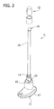
- FIG. 2 is a perspective of a probe of the thermometer
- FIG. 2A is a schematic perspective showing the probe as received in a patient's mouth
- FIG. 3 is a schematic, fragmentary elevation of internal components of the probe showing a configuration of a first embodiment
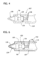
- FIG. 4 is a schematic, fragmentary elevation of a probe of a second embodiment
- FIG. 5 is a perspective of a probe cover
- FIG. 6 is an enlarged, fragmentary elevation similar to Fig. 4 but showing the probe cover on the probe;
- FIG. 7 is an enlarged, fragmentary elevation similar to Fig. 4 but showing a probe and probe cover of a third embodiment
- FIG. 8 is a schematic, fragmentary elevation of internal components of the probe showing a configuration of a fourth embodiment.
- the electronic thermometer comprises a temperature calculating unit, indicated generally at 3, that is sized and shaped to be held comfortably in the hand H.
- the calculating unit 3 (broadly, "a base unit") is connected by a helical cord 5 to a probe 7 (the reference numerals indicating their subjects generally). It will be appreciated that calculation electronics could be incorporated into the probe so that a separate base unit and connection cord could be omitted.
- the probe 7 is constructed for contacting the subject (e.g., a patient) and sending signals to the calculating unit 3 representative of the temperature.
- the calculating unit 3 receives the signals from the probe 7 and uses them to calculate the temperature.
- Suitable circuitry such as a programmable microcontroller 8, for performing these calculations is contained within a housing 9 of the calculating unit 3.
- the circuitry makes the calculated temperature appear on a LCD display 11 on the front of the housing 9.
- the microcontroller 8 in the calculating unit 3 can be calibrated to convert the temperature signal from the probe 7 to the temperature of the object being measured. In the illustrated embodiment, a direct temperature measurement is made.
- the microcontroller 8 could include predictive software to provide a temperature reading for exhibition on the display 11 prior to the temperature signal output from the probe 7 to the microcontroller becoming steady state. Other information desirably can appear on the display 11, as will be appreciated by those of ordinary skill in the art.
- a panel 11A of buttons for operating the thermometer 1 is located just above the display 11.
- the housing 9 includes a compartment (not shown) generally at the rear of the housing that can receive a distal portion of the probe 7 into the housing for holding the probe and isolating the distal portion from the environment when not in use.
- Figure 1 illustrates the probe 7 being pulled by the other hand Hl from the compartment in preparation for use.
- the housing 9 also has a receptacle 13 that receives a suitable container such as a carton C of probe covers 12 (see, Fig. 2 ). In use, the top of the carton C is removed, exposing open ends of the probe covers. The distal portion of the probe 7 can be inserted into the open end of the carton C and one of the probe covers 12 can be releasably secured in an annular recess 14.
- Pushers 15 are located at the junction of a handle 17 of the probe 7 with a probe shaft 19.
- the probe shaft is protected from contamination by the cover 12 when the distal portion of the probe shaft 19 is inserted, for example, into a patient's mouth ( Fig. 2A ).
- the probe shaft 19 is relatively long and thin.
- the ratio of the length of the probe shaft to its diameter is at least about three, in another embodiment, the ratio is at least about six, in a yet another embodiment, the ratio is at least about twelve, and in still another embodiment the ratio is about eighteen.
- the length of the probe shaft is measured from where it exits the probe handle 17 above the recess 14 to its distal end from which the metal tip 29 projects.
- the diameter of the probe shaft 19 is generally constant along its length, but an average or median diameter might be used to calculate the ratio of length to diameter of a non-constant diameter probe shaft.
- a button 21 on the probe handle 17 can be depressed to cause the pushers 15 to move forward for releasing the probe cover 12 from the probe shaft 19. Subsequent to use, the probe cover 12 is discarded.
- Other ways of capturing and releasing probe covers may be used without departing from the scope of the present invention.
- One aspect of the present invention is directed to a temperature sensing arrangement that senses infrared radiation to acquire the body temperature ( Fig. 2A ).
- the preferred embodiments of the present invention are for acquisition of body temperature, it will be understood that the principles of the present invention may be applied to measure the temperature of an "object," be it a living being or otherwise.
- the object being measured may be solid, liquid or gas.
- the internal components of the probe 7 include a temperature sensor 25, a waveguide 27 and a conical metal tip 29 (the reference numerals indicating their subjects generally).
- the tip 29 is made of aluminum, but other materials (including non-metals) may be used within the scope of the present invention.
- the metal tip 29 is mounted on a distal end of the probe shaft 19 and is heated up by contact with tissue in the mouth.
- the metal tip 29 has a high thermal conductivity, low heat capacity and low mass, and a shape selected to warm rapidly to the temperature of the body tissue in thermal contact with the tip.
- the conical shape of the tip 29 improves its emissivity and reduces reflection of infrared radiation. Infrared radiation emitted from the heated metal tip 29 is received into the waveguide 27 that has a reflective material (e.g., a layer of gold) on its interior.
- the waveguide 27 transmits the infrared radiation with minimal losses along its length to a proximal end where it impinges upon the temperature sensor 25.
- the temperature sensor comprises a thermoelectric effect sensor in the form of a thermopile 31 positioned adjacent to the proximal end of the waveguide 27. It will be understood that other thermoelectric effect sensors (not shown), such as pyroelectric sensors, microbolometers or other sensors that do not employ the thermoelectric effect may be used without departing from the scope of the present invention.
- the thermopile 31 emits a voltage corresponding to the temperature of the "hot junction" relative to the "cold junctions". It includes a plurality of individual thermocouples (not shown) connected in series. Each thermocouple has a cold junction and a hot junction. See, U.S. Pat. No. 4,722,612 of Junkert et al. issued Feb. 2, 1988 .
- the hot junction is typically formed by a small blackbody ("a target area") onto which the infrared radiation is directed. The blackbody rapidly heats to a temperature corresponding to the temperature of the object radiating the infrared radiation.
- the thermopile 31 generates an analog output signal (voltage) representative of the amount of infrared radiation that impinges thereon.
- the illustrated embodiment of the present invention is designed to sense infrared radiation emitted by the metal tip 29, which is related to the temperature of the biological surface tissue in the mouth of a human body. It is to be understood that a thermometer incorporating the principles of the present invention could be used to measure the temperature of tissue at other locations on the body (e.g., in the rectum, axilla, etc.) within the scope of the present invention.
- the temperature sensor 25 further includes a second sensor secured to the thermopile 31 in a suitable manner or incorporated into the thermopile.
- the second sensor generates an analog output signal (resistance) representative of the temperature of the thermopile 31.
- One sensor suitable for this purpose is a thermistor 33.
- the second sensor or thermistor 33 is sometimes referred to as the ambient sensor because it effectively measures the ambient temperature of the room in which the thermometer 1 is being used, and thus the temperature of the thermopile 31. In the illustrated embodiment, it is necessary to know the temperature of the thermopile 31 in determining the actual body temperature from its output signals.
- the temperature sensor 25 is preferably sealed within the probe shaft 19.
- the probe cover 12 is received over the metal tip 29 and probe shaft 19 in use of the thermometer.
- the probe cover 12 fits over the distal end of the probe 7 and is releasably held on the probe shaft 19 by the annular recess 14.
- the probe cover 12 is described in more detail hereinafter with respect to a second
- a tubular waveguide 27 is placed in proximity with the viewing aperture of the thermopile 31. It is preferable that the waveguide 27 be brass or copper with the inside diameter plated with gold to achieve the highest possible reflectivity in the infrared region of the spectrum, i.e. a wavelength of 8-12 microns.
- a probe of a second embodiment (indicated generally at 107) is shown to comprise a probe shaft 119 and a metal tip 129 mounted in a distal end of the probe shaft (only a fragmentary portion of which is shown). Parts of the probe 107 corresponding to those of the probe 7 of the first embodiment are given the same reference numeral, plus "100". Unlike the probe 7 of the first embodiment, there is no waveguide 27, and a temperature sensor 125 is mounted by a collar 126 within the probe shaft 119 near the distal end of the probe shaft.
- thermopile (not shown) of the temperature sensor 125 and is not transmitted by any intervening structure (e.g., a waveguide) to the temperature sensor.
- the cone-shaped field of vision FV of the thermopile is illustrated in Fig. 4 , and is equal to the width of the base of the metal tip 129 where the field of vision intersects the base of the metal tip.
- the sensor is placed as far away from the distal end of the probe 107 as possible. In that case, sensor 125 would have a narrow field of vision so that it sees only the tip 129.
- the thermopile is able to see the entire metal tip 129.
- thermometer 125 An example of suitable arrangement of the temperature sensor 125 near the distal end of a probe in the tympanic thermometer context is shown in co-assigned U.S. Patent application Serial No. 10/480,428, filed December 10, 2003 , the disclosure of which is incorporated herein by reference. A similar arrangement may be used here. Wires 128 from the temperature sensor 125 extend through the probe shaft 119 to its handle (not shown). A flex circuit (not shown) or other suitable electrical connection structure may be used.
- the probe cover 112 for covering the probe shaft 119 in use to prevent contamination and reduction or loss of operability (e.g., by saliva) upon insertion into the mouth.
- the probe cover 112 includes a tubular body 116 of and a stretchable film 118 closing one end of the tubular body.
- the film 118 can be constructed, for example, from a lower density plastic (e.g., low density polyethylene (LDPE)), while the body 116 is constructed from a higher density plastic (e.g., high density polyethylene (HDPE)). As shown in Fig. 5 prior to placement on the probe shaft 119, the film 118 extends generally perpendicularly across the end of the tubular body.
- LDPE low density polyethylene
- HDPE high density polyethylene
- the film 118 When applied over the probe shaft 119, the film 118 engages and is stretched over the metal tip 129 of the probe shaft. Thus, the film 118 closely conforms to the shape of the exterior surface of the metal tip 129 when the probe cover 112 is mounted on the probe shaft 119. Thus, conductive heat transfer from the body tissue through the film 118 to the metal tip 129 is facilitated.
- a third embodiment of the probe 207 is shown in Fig. 7 to comprise a probe shaft 219 and a temperature sensor 225 mounted near the distal end of the probe shaft similar to the embodiment of Figs. 4-6 . Parts of the probe 207 corresponding to those of the probe 107 will be given the same reference numeral, plus "100".
- the metal tip 125 is omitted.
- the probe shaft 219 has a transparent window 220 closing off its distal end.
- the window 220 need only be transparent to infrared radiation.
- the construction of the probe 207 can be the same as the probe 107 of the second embodiment.
- a probe cover 212 of the third embodiment includes a tubular body 216 and film 218 closing the distal end of the body.
- the tubular body 216 has spacers 221 (two of which are shown) on its interior that engage and space the tubular body from the probe shaft 219.
- the spacers 221 may have other configurations, different in number or may be omitted without departing from the scope of the present invention.
- the probe cover film 218 (unlike the first two embodiments) does not engage the end of the probe shaft 219, but is spaced axially from the end of the probe shaft.
- a central region 222 of the film has metal deposited on it. It is to be understood that the metal deposit need not be located in or confined to a central region.
- the entire film may be metallized.
- the metal central region 222 replaces the metal tip 29, 129 of the prior two embodiments.
- the field of vision of the thermopile (not shown) of the temperature sensor 225 encompasses the central region 222.
- the central region can be formed by other materials having high thermal conductivity, low heat capacity and low mass.
- Components of a probe of a fourth embodiment are show in Fig. 8 to comprise a temperature sensor 325, a waveguide 327 and a lens 328.
- the probe of the fourth embodiment generally corresponds to the probe 7 of the first embodiment in that both have a waveguide (27 and 327). Parts of the probe of the fourth embodiment corresponding to parts of the probe 7 of the first embodiment will be given the same reference numerals, plus "300".
- infrared radiation from body tissue e.g., tissue inside the mouth
- the waveguide conducts the infrared radiation to the temperature sensor 325 in substantially the same way as the waveguide 27 of the first embodiment.
- the temperature sensor 325 directly views the body tissue, not any intermediate structure such as a metal tip.
Abstract
Description
- The present invention generally relates to a thermometer and more specifically to an infrared thermometer that is suitable for oral body temperature measurement.
- Electronic thermometers are widely used in the healthcare field for measuring a patient's body temperature. Typical electronic thermometers have the form of a probe with an elongated shaft. Electronic temperature sensors such as thermistors or other temperature sensitive elements are contained within the shaft portion. In one version, the probe includes a cup-shaped aluminum tip at its distal end. A thermistor is placed in thermal contact with the aluminum tip inside the probe. When a distal end portion is placed, for example, in a patient's mouth, the tip is heated up by the patient's body and the thermistor measures the temperature of the tip. Additional electronics connected to the electronic sensor components may be contained within a base unit connected by wire to the shaft portion or may be contained within a handle of the shaft portion, for example. Electronic components receive input from the sensor components to compute the patient's temperature. The temperature is then typically displayed on a visual output device such as a seven segment numerical display device. Additional features of known electronic thermometers include audible temperature level notification such as a beep or tone alert signal. A disposable cover or sheath is typically fitted over the shaft portion and disposed after each use of the thermometer for sanitary reasons.
- Electronic thermometers have many advantages over conventional thermometers and have essentially replaced the use of conventional glass thermometers in the healthcare field. One advantage of electronic thermometers over their conventional glass counterparts is the speed at which a temperature reading can be taken. Several procedures are used to promote a rapid measurement of the subject's temperature. One technique employed is to use predictive algorithms as part of thermometer logic to extrapolate the temperature measurements from the thermistor in contact with the tip to arrive at a temperature reading in advance of the tip reaching equilibrium with the body temperature. Another technique that can be employed simultaneously with a predictive algorithm is to heat the probe to near the body temperature so that part of the probe away from the tip does not act as a heat sink, allowing the tip to reach a temperature close to the body temperature more rapidly. Heating can be accomplished by a thermistor placed in contact with the probe. Another thermistor may be placed in contact with the probe to measure the amount the resistor is heating the probe, which is used to control the heating. It is also known to use an isolator to reduce heat loss from the tip to other parts of the probe.
- It would be desirable to improve further upon the conventional electronic thermometer. In particular, the electronic thermometer is challenging to assemble because of the various small components that must be placed in the probe.
Moreover, although the electronic thermometer quickly provides a body temperature measurement, particularly as compared to conventional glass thermometers, additional speed would be desirable. Moreover in order to obtain the temperature quickly, the probe is heated, which causes a power drain on the batteries. Still further, rapid temperature measurement also relies upon the use of predictive algorithms that add to the complexity of the thermometer. - In one aspect of the present invention, an infrared electronic thermometer for measuring temperature of an object generally comprises a display adapted to show the temperature measured by the thermometer and an elongate probe shaft having an interior. An infrared sensor mounted on the shaft and located on the interior of the probe shaft is operatively connected to the display for electronic communication between the display and the probe. The infrared sensor is capable of sending a signal indicative of the measured temperature. A probe tip mounted on the probe shaft generally at a distal end thereof is adapted to rapidly equilibrate to a temperature corresponding to the temperature of the object in thermal contact with the probe tip. The infrared sensor is disposed for measuring infrared radiation from the probe tip.
- In another aspect of the present invention, a non-tympanic electronic thermometer for measuring temperature of an object generally comprises a display adapted to show the temperature measured by the thermometer. A probe includes an elongate probe shaft having an interior and a probe tip at a distal end of the shaft. The probe shaft has a ratio of length to diameter of at least about 3. An infrared radiation sensor is adapted to receive infrared radiation and to provide a signal indicative of the temperature of the object. The temperature sensor being in operative electronic communication with the display for sending the temperature indicative signal to the display.
- In yet another aspect of the present invention, a method of indirect measurement of temperature of an object generally comprises placing a probe of an electronic thermometer including a probe tip in contact with the object. Heat transfer from the object to the probe tip to rapidly heat up the probe tip to an equilibrium temperature is allowed and infrared radiation from the tip is sensed with a sensor sealed in a probe shaft of the probe. A signal corresponding to the temperature of the probe tip detected by the sensor is generated. The signal is communicated the sensor to a display of the electronic thermometer. The detected temperature is shown on the display.
- In still another aspect of the present invention, a probe cover for an infrared electronic thermometer generally comprises a generally tubular body having an open end and a closed end. The body is sized and shaped to receive a probe of the infrared electronic thermometer into the body through the open end. The body includes a blackbody portion at said closed end of the body. The blackbody portion is formed of a material that rapidly equilibrates to a temperature corresponding to the temperature of an object for viewing by a sensor of the electronic thermometer to measure the temperature of the object.
- Other objects and features will be in part apparent and in part pointed out hereinafter.
-
FIG. 1 is a perspective of an infrared electronic thermometer; -
FIG. 1A is a diagrammatic representation of the thermometer; -
FIG. 2 is a perspective of a probe of the thermometer; -
FIG. 2A is a schematic perspective showing the probe as received in a patient's mouth; -
FIG. 3 is a schematic, fragmentary elevation of internal components of the probe showing a configuration of a first embodiment; -
FIG. 4 is a schematic, fragmentary elevation of a probe of a second embodiment; -
FIG. 5 is a perspective of a probe cover; -
FIG. 6 is an enlarged, fragmentary elevation similar toFig. 4 but showing the probe cover on the probe; -
FIG. 7 is an enlarged, fragmentary elevation similar toFig. 4 but showing a probe and probe cover of a third embodiment, and -
FIG. 8 is a schematic, fragmentary elevation of internal components of the probe showing a configuration of a fourth embodiment. - Corresponding reference characters indicate corresponding parts throughout the drawings.
- Referring now to the drawings, and in particular to
Figs. 1 and2 , an electronic thermometer constructed according to the principles of the present invention is indicated generally at 1. The electronic thermometer comprises a temperature calculating unit, indicated generally at 3, that is sized and shaped to be held comfortably in the hand H. The calculating unit 3 (broadly, "a base unit") is connected by ahelical cord 5 to a probe 7 (the reference numerals indicating their subjects generally). It will be appreciated that calculation electronics could be incorporated into the probe so that a separate base unit and connection cord could be omitted. Theprobe 7 is constructed for contacting the subject (e.g., a patient) and sending signals to the calculatingunit 3 representative of the temperature. The calculatingunit 3 receives the signals from theprobe 7 and uses them to calculate the temperature. Suitable circuitry, such as aprogrammable microcontroller 8, for performing these calculations is contained within a housing 9 of the calculatingunit 3. The circuitry makes the calculated temperature appear on aLCD display 11 on the front of the housing 9. Themicrocontroller 8 in the calculatingunit 3 can be calibrated to convert the temperature signal from theprobe 7 to the temperature of the object being measured. In the illustrated embodiment, a direct temperature measurement is made. However, it will be understood that themicrocontroller 8 could include predictive software to provide a temperature reading for exhibition on thedisplay 11 prior to the temperature signal output from theprobe 7 to the microcontroller becoming steady state. Other information desirably can appear on thedisplay 11, as will be appreciated by those of ordinary skill in the art. Apanel 11A of buttons for operating the thermometer 1 is located just above thedisplay 11. - The housing 9 includes a compartment (not shown) generally at the rear of the housing that can receive a distal portion of the
probe 7 into the housing for holding the probe and isolating the distal portion from the environment when not in use.Figure 1 illustrates theprobe 7 being pulled by the other hand Hl from the compartment in preparation for use. The housing 9 also has areceptacle 13 that receives a suitable container such as a carton C of probe covers 12 (see,Fig. 2 ). In use, the top of the carton C is removed, exposing open ends of the probe covers. The distal portion of theprobe 7 can be inserted into the open end of the carton C and one of the probe covers 12 can be releasably secured in anannular recess 14.Pushers 15 are located at the junction of ahandle 17 of theprobe 7 with aprobe shaft 19. The probe shaft is protected from contamination by thecover 12 when the distal portion of theprobe shaft 19 is inserted, for example, into a patient's mouth (Fig. 2A ). In order to be used for insertion into the mouth or other larger cavity (e.g., the rectum), theprobe shaft 19 is relatively long and thin. For example in one embodiment, the ratio of the length of the probe shaft to its diameter is at least about three, in another embodiment, the ratio is at least about six, in a yet another embodiment, the ratio is at least about twelve, and in still another embodiment the ratio is about eighteen. The length of the probe shaft is measured from where it exits the probe handle 17 above therecess 14 to its distal end from which themetal tip 29 projects. The diameter of theprobe shaft 19 is generally constant along its length, but an average or median diameter might be used to calculate the ratio of length to diameter of a non-constant diameter probe shaft. Abutton 21 on the probe handle 17 can be depressed to cause thepushers 15 to move forward for releasing the probe cover 12 from theprobe shaft 19. Subsequent to use, theprobe cover 12 is discarded. Other ways of capturing and releasing probe covers may be used without departing from the scope of the present invention. - One aspect of the present invention is directed to a temperature sensing arrangement that senses infrared radiation to acquire the body temperature (
Fig. 2A ). Although the preferred embodiments of the present invention are for acquisition of body temperature, it will be understood that the principles of the present invention may be applied to measure the temperature of an "object," be it a living being or otherwise. Moreover, the object being measured may be solid, liquid or gas. In a first embodiment illustrated inFig. 3 , the internal components of theprobe 7 include atemperature sensor 25, awaveguide 27 and a conical metal tip 29 (the reference numerals indicating their subjects generally). In the illustrated embodiments, thetip 29 is made of aluminum, but other materials (including non-metals) may be used within the scope of the present invention. These components are supported by the probe shaft 19 (not shown inFig. 3 ). Themetal tip 29 is mounted on a distal end of theprobe shaft 19 and is heated up by contact with tissue in the mouth. Themetal tip 29 has a high thermal conductivity, low heat capacity and low mass, and a shape selected to warm rapidly to the temperature of the body tissue in thermal contact with the tip. The conical shape of thetip 29 improves its emissivity and reduces reflection of infrared radiation. Infrared radiation emitted from theheated metal tip 29 is received into thewaveguide 27 that has a reflective material (e.g., a layer of gold) on its interior. Thewaveguide 27 transmits the infrared radiation with minimal losses along its length to a proximal end where it impinges upon thetemperature sensor 25. The temperature sensor comprises a thermoelectric effect sensor in the form of athermopile 31 positioned adjacent to the proximal end of thewaveguide 27. It will be understood that other thermoelectric effect sensors (not shown), such as pyroelectric sensors, microbolometers or other sensors that do not employ the thermoelectric effect may be used without departing from the scope of the present invention. - The
thermopile 31 emits a voltage corresponding to the temperature of the "hot junction" relative to the "cold junctions". It includes a plurality of individual thermocouples (not shown) connected in series. Each thermocouple has a cold junction and a hot junction. See,U.S. Pat. No. 4,722,612 of Junkert et al. issued Feb. 2, 1988 . The hot junction is typically formed by a small blackbody ("a target area") onto which the infrared radiation is directed. The blackbody rapidly heats to a temperature corresponding to the temperature of the object radiating the infrared radiation. Thethermopile 31 generates an analog output signal (voltage) representative of the amount of infrared radiation that impinges thereon. The illustrated embodiment of the present invention is designed to sense infrared radiation emitted by themetal tip 29, which is related to the temperature of the biological surface tissue in the mouth of a human body. It is to be understood that a thermometer incorporating the principles of the present invention could be used to measure the temperature of tissue at other locations on the body (e.g., in the rectum, axilla, etc.) within the scope of the present invention. - The
temperature sensor 25 further includes a second sensor secured to thethermopile 31 in a suitable manner or incorporated into the thermopile. The second sensor generates an analog output signal (resistance) representative of the temperature of thethermopile 31. One sensor suitable for this purpose is athermistor 33. The second sensor orthermistor 33 is sometimes referred to as the ambient sensor because it effectively measures the ambient temperature of the room in which the thermometer 1 is being used, and thus the temperature of thethermopile 31. In the illustrated embodiment, it is necessary to know the temperature of thethermopile 31 in determining the actual body temperature from its output signals. Thetemperature sensor 25 is preferably sealed within theprobe shaft 19. The probe cover 12 is received over themetal tip 29 andprobe shaft 19 in use of the thermometer. The probe cover 12 fits over the distal end of theprobe 7 and is releasably held on theprobe shaft 19 by theannular recess 14. The probe cover 12 is described in more detail hereinafter with respect to a second embodiment of the thermometer. - A
tubular waveguide 27 is placed in proximity with the viewing aperture of thethermopile 31. It is preferable that thewaveguide 27 be brass or copper with the inside diameter plated with gold to achieve the highest possible reflectivity in the infrared region of the spectrum, i.e. a wavelength of 8-12 microns. - Referring now to
Fig. 4 , a probe of a second embodiment (indicated generally at 107) is shown to comprise aprobe shaft 119 and ametal tip 129 mounted in a distal end of the probe shaft (only a fragmentary portion of which is shown). Parts of theprobe 107 corresponding to those of theprobe 7 of the first embodiment are given the same reference numeral, plus "100". Unlike theprobe 7 of the first embodiment, there is nowaveguide 27, and atemperature sensor 125 is mounted by acollar 126 within theprobe shaft 119 near the distal end of the probe shaft. Thus, infrared radiation emitted from themetal tip 129 is seen directly by a thermopile (not shown) of thetemperature sensor 125 and is not transmitted by any intervening structure (e.g., a waveguide) to the temperature sensor. The cone-shaped field of vision FV of the thermopile is illustrated inFig. 4 , and is equal to the width of the base of themetal tip 129 where the field of vision intersects the base of the metal tip. In order to isolatesensor 125 from heat in the oral cavity, the sensor is placed as far away from the distal end of theprobe 107 as possible. In that case,sensor 125 would have a narrow field of vision so that it sees only thetip 129. Thus, the thermopile is able to see theentire metal tip 129. An example of suitable arrangement of thetemperature sensor 125 near the distal end of a probe in the tympanic thermometer context is shown in co-assignedU.S. Patent application Serial No. 10/480,428, filed December 10, 2003 Wires 128 from thetemperature sensor 125 extend through theprobe shaft 119 to its handle (not shown). A flex circuit (not shown) or other suitable electrical connection structure may be used. - Referring now also to
Figs. 5 and6 , a probe cover generally indicated at 112 for covering theprobe shaft 119 in use to prevent contamination and reduction or loss of operability (e.g., by saliva) upon insertion into the mouth. Theprobe cover 112 includes atubular body 116 of and astretchable film 118 closing one end of the tubular body. Thefilm 118 can be constructed, for example, from a lower density plastic (e.g., low density polyethylene (LDPE)), while thebody 116 is constructed from a higher density plastic (e.g., high density polyethylene (HDPE)). As shown inFig. 5 prior to placement on theprobe shaft 119, thefilm 118 extends generally perpendicularly across the end of the tubular body.
When applied over theprobe shaft 119, thefilm 118 engages and is stretched over themetal tip 129 of the probe shaft. Thus, thefilm 118 closely conforms to the shape of the exterior surface of themetal tip 129 when theprobe cover 112 is mounted on theprobe shaft 119. Thus, conductive heat transfer from the body tissue through thefilm 118 to themetal tip 129 is facilitated. - A third embodiment of the
probe 207 is shown inFig. 7 to comprise aprobe shaft 219 and atemperature sensor 225 mounted near the distal end of the probe shaft similar to the embodiment ofFigs. 4-6 . Parts of theprobe 207 corresponding to those of theprobe 107 will be given the same reference numeral, plus "100". In the third embodiment, themetal tip 125 is omitted. Instead, theprobe shaft 219 has atransparent window 220 closing off its distal end. For purposes of the present invention, thewindow 220 need only be transparent to infrared radiation. In other respects, the construction of theprobe 207 can be the same as theprobe 107 of the second embodiment. - A
probe cover 212 of the third embodiment includes atubular body 216 andfilm 218 closing the distal end of the body. Thetubular body 216 has spacers 221 (two of which are shown) on its interior that engage and space the tubular body from theprobe shaft 219. Thespacers 221 may have other configurations, different in number or may be omitted without departing from the scope of the present invention. When fully seated on theprobe 207, the probe cover film 218 (unlike the first two embodiments) does not engage the end of theprobe shaft 219, but is spaced axially from the end of the probe shaft. Acentral region 222 of the film has metal deposited on it. It is to be understood that the metal deposit need not be located in or confined to a central region. For example, the entire film may be metallized. The metalcentral region 222 replaces themetal tip temperature sensor 225 encompasses thecentral region 222. The central region can be formed by other materials having high thermal conductivity, low heat capacity and low mass. - Components of a probe of a fourth embodiment are show in
Fig. 8 to comprise atemperature sensor 325, awaveguide 327 and alens 328. The probe of the fourth embodiment generally corresponds to theprobe 7 of the first embodiment in that both have a waveguide (27 and 327). Parts of the probe of the fourth embodiment corresponding to parts of theprobe 7 of the first embodiment will be given the same reference numerals, plus "300". In the fourth embodiment, infrared radiation from body tissue (e.g., tissue inside the mouth) is focused by the lens into thewaveguide 327. The waveguide conducts the infrared radiation to thetemperature sensor 325 in substantially the same way as thewaveguide 27 of the first embodiment. Thus in the fourth embodiment thetemperature sensor 325 directly views the body tissue, not any intermediate structure such as a metal tip. - When introducing elements of the present invention or the preferred embodiments(s) thereof, the articles "a", "an", "the" and "said" are intended to mean that there are one or more of the elements. The terms "comprising", "including" and "having" are intended to be inclusive and mean that there may be additional elements other than the listed elements.
- In view of the above, it will be seen that the several objects of the invention are achieved and other advantageous results attained.
- As various changes could be made in the above thermometers and methods of their use without departing from the scope of the invention, it is intended that all matter contained in the above description and shown in the accompanying drawings shall be interpreted as illustrative and not in a limiting sense.
Claims (6)
- A probe cover for an infrared electronic thermometer comprising:a generally tubular body having open first and second ends, the body being sized and shaped to receive a probe of the infrared electronic thermometer into the body through the first end; anda film closing the second end of the body, the film including a metallic region defining a blackbody portion for rapidly equilibrating to a temperature corresponding to the temperature of an object for viewing by a sensor of the electronic thermometer to measure the temperature of the object.
- A probe cover as set forth in claim 1 wherein the blackbody portion is located in a central region of the film.
- A probe cover as set forth in claim 1 or 2 wherein the blackbody portion is made of a different material than the tubular body.
- A probe cover as set forth in any one of claims 1 to 3 wherein the cover comprises at least two spacers on an interior of the tubular body for engaging and spacing the body from the probe.
- A probe cover as set forth in any one of claims 1 to 4 wherein when the probe is received in the probe cover, the film is spaced axially away from the probe so that the film does not engage the probe.
- A probe cover for an infrared electronic thermometer comprising:a generally tubular body having open first and second ends, the body being sized and shaped to receive a probe of the infrared electronic thermometer into the body through the first end; anda film closing the second end of the body, the film including a metallic region defining a blackbody portion for rapidly equilibrating to a temperature corresponding to the temperature of an object for viewing by a sensor of the electronic thermometer to measure the temperature of the object, the blackbody portion being made of a different material than the tubular body.
Applications Claiming Priority (2)
| Application Number | Priority Date | Filing Date | Title |
|---|---|---|---|
| US11/379,743 US20070248141A1 (en) | 2006-04-21 | 2006-04-21 | Infrared thermometer and probe cover thereof |
| EP07007704A EP1847820A3 (en) | 2006-04-21 | 2007-04-16 | Infrared thermometer and probe cover thereof |
Related Parent Applications (2)
| Application Number | Title | Priority Date | Filing Date |
|---|---|---|---|
| EP07007704A Division EP1847820A3 (en) | 2006-04-21 | 2007-04-16 | Infrared thermometer and probe cover thereof |
| EP07007704.5 Division | 2007-04-16 |
Publications (2)
| Publication Number | Publication Date |
|---|---|
| EP2261619A2 true EP2261619A2 (en) | 2010-12-15 |
| EP2261619A3 EP2261619A3 (en) | 2016-08-24 |
Family
ID=38437711
Family Applications (3)
| Application Number | Title | Priority Date | Filing Date |
|---|---|---|---|
| EP07007704A Withdrawn EP1847820A3 (en) | 2006-04-21 | 2007-04-16 | Infrared thermometer and probe cover thereof |
| EP10184378.7A Withdrawn EP2261619A3 (en) | 2006-04-21 | 2007-04-16 | Infrared thermometer and probe cover thereof |
| EP08100594A Active EP1906160B1 (en) | 2006-04-21 | 2007-04-16 | Infrared thermometer and probe cover thereof |
Family Applications Before (1)
| Application Number | Title | Priority Date | Filing Date |
|---|---|---|---|
| EP07007704A Withdrawn EP1847820A3 (en) | 2006-04-21 | 2007-04-16 | Infrared thermometer and probe cover thereof |
Family Applications After (1)
| Application Number | Title | Priority Date | Filing Date |
|---|---|---|---|
| EP08100594A Active EP1906160B1 (en) | 2006-04-21 | 2007-04-16 | Infrared thermometer and probe cover thereof |
Country Status (13)
| Country | Link |
|---|---|
| US (3) | US20070248141A1 (en) |
| EP (3) | EP1847820A3 (en) |
| JP (1) | JP2007301356A (en) |
| KR (1) | KR100882032B1 (en) |
| CN (2) | CN101059371B (en) |
| AT (1) | ATE533036T1 (en) |
| AU (1) | AU2007201761B2 (en) |
| BR (1) | BRPI0701281A2 (en) |
| CA (1) | CA2584742C (en) |
| DK (1) | DK1906160T3 (en) |
| ES (1) | ES2374099T3 (en) |
| HK (1) | HK1108294A1 (en) |
| IL (1) | IL182617A0 (en) |
Cited By (3)
| Publication number | Priority date | Publication date | Assignee | Title |
|---|---|---|---|---|
| CN107014494A (en) * | 2017-03-10 | 2017-08-04 | 北京振兴计量测试研究所 | A kind of high precision surface source blackbody radiation source device applied under the conditions of vacuum and low temperature |
| CN111721424A (en) * | 2019-03-20 | 2020-09-29 | 北京振兴计量测试研究所 | Method for mounting temperature sensor for infrared radiometer in vacuum low-temperature environment |
| CN111721419A (en) * | 2019-03-20 | 2020-09-29 | 北京振兴计量测试研究所 | External calibration source and temperature control system for infrared radiometer in vacuum low-temperature environment |
Families Citing this family (15)
| Publication number | Priority date | Publication date | Assignee | Title |
|---|---|---|---|---|
| US8303177B2 (en) * | 2008-03-31 | 2012-11-06 | Hsueh-Yu Lu | Pre-heat type clinical thermometer |
| EP2302342A1 (en) * | 2009-09-16 | 2011-03-30 | Microlife Intellectual Property GmbH | Infrared thermometer |
| US8540424B2 (en) | 2009-12-18 | 2013-09-24 | Covidien Lp | Cover for shaft of electronic thermometer probe |
| US8996096B2 (en) * | 2011-07-19 | 2015-03-31 | Welch Allyn, Inc. | Systems and methods for determining patient temperature |
| US9357930B2 (en) * | 2012-03-19 | 2016-06-07 | Welch Allyn, Inc. | Temperature measurement system |
| CN104541139B (en) * | 2012-08-03 | 2017-09-05 | 世美特株式会社 | For measuring high temperature contact type infrared temperature sensor, hot equipment and gas extraction system |
| DE102012215690A1 (en) * | 2012-09-05 | 2014-03-06 | Robert Bosch Gmbh | Temperature measuring device, as well as methods for temperature measurement |
| WO2014076580A2 (en) * | 2012-11-19 | 2014-05-22 | Kaz Europe Sa | Non-contact medical thermometer with distance sensing and compensation |
| US9943232B2 (en) | 2014-02-03 | 2018-04-17 | Welch Allyn, Inc. | Thermometry heating and sensing assembly |
| TWI756218B (en) * | 2016-04-20 | 2022-03-01 | 美商菲歐普提斯公司 | Probe cover for an oximeter device, kit and method for forming a kit |
| ES2663527B1 (en) * | 2016-07-21 | 2019-02-07 | Bsh Electrodomesticos Espana Sa | Sensor device and household appliance with said sensor device |
| CN107560729A (en) * | 2017-09-22 | 2018-01-09 | 温州益禾电子科技有限公司 | A kind of optical sensor for warmhouse booth |
| CN109827664A (en) * | 2017-11-23 | 2019-05-31 | 北京振兴计量测试研究所 | Temperature sensing device |
| US10801894B2 (en) * | 2018-07-18 | 2020-10-13 | Radiant Innovation Inc. | Reflecting shell and temperature detecting device |
| JP7162835B2 (en) * | 2018-09-19 | 2022-10-31 | 国立研究開発法人産業技術総合研究所 | blackbody furnace |
Citations (1)
| Publication number | Priority date | Publication date | Assignee | Title |
|---|---|---|---|---|
| US4722612A (en) | 1985-09-04 | 1988-02-02 | Wahl Instruments, Inc. | Infrared thermometers for minimizing errors associated with ambient temperature transients |
Family Cites Families (167)
| Publication number | Priority date | Publication date | Assignee | Title |
|---|---|---|---|---|
| US3282106A (en) * | 1963-01-28 | 1966-11-01 | Barnes Eng Co | Method of measuring body temperature |
| GB1065848A (en) | 1963-12-24 | 1967-04-19 | Hartmann Fibre Ltd | Improvements in or relating to nestable trays |
| US3626758A (en) * | 1969-12-15 | 1971-12-14 | Caterpillar Tractor Co | Remote radiation temperature sensor |
| US3738479A (en) * | 1970-04-14 | 1973-06-12 | S Sato | Disposable rigid thermometer probe cover |
| US3681991A (en) * | 1970-07-06 | 1972-08-08 | United States Banknote Corp | Electronic thermometer |
| US3832669A (en) * | 1970-08-10 | 1974-08-27 | Royal Medical Corp | Temperature-sensing device |
| US3765238A (en) * | 1970-12-29 | 1973-10-16 | Showa Denko Kk | Heat flow meter |
| US3822593A (en) * | 1972-01-12 | 1974-07-09 | Diatek Inc | Clinical thermometer probe and disposable cover therefor |
| US3872728A (en) * | 1972-10-10 | 1975-03-25 | Michael F Joyce | Electronic temperature measuring instrument |
| US3884219A (en) * | 1973-04-02 | 1975-05-20 | Medical Monitor Systems | System for determining temperature and respiration rate |
| US3949740A (en) * | 1973-08-23 | 1976-04-13 | Products International Marketing | Disposable speculum for tympanic thermometer |
| US3915371A (en) | 1973-10-04 | 1975-10-28 | Keyes Fibre Co | Nestable tray with cup supporting recess |
| US3905232A (en) * | 1973-10-05 | 1975-09-16 | Ivac Corp | Electronic thermometer |
| US3942891A (en) * | 1975-01-29 | 1976-03-09 | Barnes Engineering Company | Radiometer probe |
| US4007832A (en) * | 1975-04-10 | 1977-02-15 | Roi Corporation | Electronic thermometer |
| US4497585A (en) * | 1975-04-10 | 1985-02-05 | Roi Corporation | Electronic thermometer |
| US4008614A (en) * | 1976-04-28 | 1977-02-22 | Johnson & Johnson | Removable probe unit for electronic measuring system |
| US4159766A (en) * | 1976-11-01 | 1979-07-03 | Diatek, Inc. | Cover for temperature sensing probe |
| US4117926A (en) * | 1977-01-12 | 1978-10-03 | Johnson & Johnson | Probe cover |
| US4143765A (en) * | 1977-01-26 | 1979-03-13 | Moss Iii L Howard | Shipper tray for tissue culture dishes |
| US4183248A (en) * | 1978-08-08 | 1980-01-15 | Rwb Labs | Fast response electronic thermometer probe |
| US4349109A (en) * | 1980-10-20 | 1982-09-14 | Medical Laboratory Automation, Inc. | Disposable pipette tips and trays therefor |
| US4527896A (en) * | 1982-03-04 | 1985-07-09 | Mikron Instrument Company, Inc. | Infrared transducer-transmitter for non-contact temperature measurement |
| US4457633A (en) * | 1982-03-26 | 1984-07-03 | Kidde, Inc. | Temperature probe cover |
| US4576486A (en) * | 1983-08-23 | 1986-03-18 | The United States Of America As Represented By The Secretary Of Commerce | Optical fiber thermometer |
| JPS6172071A (en) | 1984-09-17 | 1986-04-14 | Yuuhoo Chem Kk | Coating agent composition |
| US5179936A (en) * | 1984-10-23 | 1993-01-19 | Intelligent Medical Systems, Inc. | Disposable speculum with membrane bonding ring |
| US4662360A (en) * | 1984-10-23 | 1987-05-05 | Intelligent Medical Systems, Inc. | Disposable speculum |
| US4602642A (en) * | 1984-10-23 | 1986-07-29 | Intelligent Medical Systems, Inc. | Method and apparatus for measuring internal body temperature utilizing infrared emissions |
| US4790324A (en) * | 1984-10-23 | 1988-12-13 | Intelligent Medical Systems, Inc. | Method and apparatus for measuring internal body temperature utilizing infrared emissions |
| US4572365A (en) * | 1985-04-03 | 1986-02-25 | Chesebrough-Pond's Inc. | Probe cover holding and dispensing arrangement for electronic thermometer |
| US4636091A (en) * | 1985-06-27 | 1987-01-13 | Exergen Corporation | Radiation detector having temperature readout |
| US4770544A (en) * | 1985-11-15 | 1988-09-13 | General Electric Company | Temperature sensor |
| US4784149A (en) * | 1986-01-13 | 1988-11-15 | Optical Sensors, Inc. | Infrared thermometer with automatic calibration |
| DE8601223U1 (en) | 1986-01-20 | 1986-02-27 | Polarcup GmbH, 56859 Alf | Thin-walled, stackable container lid |
| WO1988007478A1 (en) * | 1987-03-26 | 1988-10-06 | Langenbeck Keith A | Storage and transport tray and tray packing system |
| FR2615484B3 (en) | 1987-05-19 | 1989-08-25 | Armor Inox Sa | SUPPORT DEVICE AND ASSOCIATED CONTAINERS FOR LOADING FOOD PRODUCTS, PARTICULARLY HAMS |
| US4854730A (en) * | 1987-08-13 | 1989-08-08 | Jacob Fraden | Radiation thermometer and method for measuring temperature |
| US5017018A (en) * | 1987-12-25 | 1991-05-21 | Nippon Steel Corporation | Clinical thermometer |
| US5046482A (en) * | 1988-03-31 | 1991-09-10 | Ivac Corporation | Disposable infrared thermometer insertion probe |
| US5060819A (en) | 1988-04-26 | 1991-10-29 | Rehrig-Pacific Company, Inc. | Nestable low depth tray |
| US4895164A (en) * | 1988-09-15 | 1990-01-23 | Telatemp Corp. | Infrared clinical thermometer |
| US5018872A (en) * | 1988-11-01 | 1991-05-28 | Diatek, Inc. | Probe assembly for infrared thermometer |
| US4911559A (en) * | 1988-11-01 | 1990-03-27 | Diatek, Inc. | Disposable probe cover assembly for medical thermometer |
| USD318812S (en) * | 1989-05-08 | 1991-08-06 | Ivac Corporation | Disposable speculum for an infrared thermometer |
| US5163418A (en) * | 1989-09-19 | 1992-11-17 | Thermoscan Inc. | Speculum cover |
| US4993424A (en) * | 1989-12-04 | 1991-02-19 | Diatek, Incorporated | Infrared medical thermometer |
| US5066142A (en) * | 1990-03-08 | 1991-11-19 | Ivac Corporation | Protective apparatus for a biomedical probe |
| DE69116903T2 (en) * | 1990-03-08 | 1996-10-02 | Ivac Corp | Thermally insulated probe |
| US5088834A (en) * | 1990-08-24 | 1992-02-18 | Thermoscan Inc. | Unitary probe cover |
| US5100018A (en) * | 1990-10-11 | 1992-03-31 | Ivac Corporation | Probe cover dispenser |
| JP3012316B2 (en) * | 1990-11-29 | 2000-02-21 | タスコジャパン株式会社 | Radiation thermometer |
| US5078507A (en) * | 1991-03-18 | 1992-01-07 | General Electric Company | Temperature sensor |
| US5318029A (en) * | 1992-02-11 | 1994-06-07 | Oasis Medical, Inc. | Tonometer shield |
| DE69327237T2 (en) * | 1992-04-01 | 2000-09-07 | Omron Tateisi Electronics Co | PROTECTIVE COVER FOR SPECULUM AND MANUFACTURING PROCESS |
| US5487607A (en) * | 1992-04-08 | 1996-01-30 | Omron Corporation | Radiation clinical thermometer |
| US5364186A (en) * | 1992-04-28 | 1994-11-15 | Luxtron Corporation | Apparatus and method for monitoring a temperature using a thermally fused composite ceramic blackbody temperature probe |
| JP2712024B2 (en) | 1992-09-19 | 1998-02-10 | 株式会社堀場製作所 | Microscope cover for eardrum thermometer |
| US5411032A (en) * | 1993-06-18 | 1995-05-02 | Infra-Temp Inc. | Electronic thermometer probe cover |
| CN1041910C (en) * | 1993-06-30 | 1999-02-03 | 欧姆龙株式会社 | Box for storage of measuring head |
| US5441702A (en) * | 1993-09-21 | 1995-08-15 | Rainin Instrument Co., Inc. | Refill pack for pipette tip racks |
| US5836692A (en) * | 1994-03-30 | 1998-11-17 | Exergen Corporation | Differential radiation detector probe |
| US5518114A (en) * | 1994-07-28 | 1996-05-21 | The Gillette Company | Cartridge dispenser |
| DE9421735U1 (en) * | 1994-09-08 | 1996-07-11 | Steinbrenner Bernd Dr | Device for providing a multitude of objects on a carrier |
| US5518560A (en) * | 1994-09-26 | 1996-05-21 | Ford Motor Company | Method and system for controlling electromagnetic field generator for adhesive curing and sensing device for use therein |
| US5857775A (en) * | 1995-09-05 | 1999-01-12 | Tyco Group S.A.R.L. | Thermometer probe having a watertight seal |
| JP2000500371A (en) * | 1995-11-18 | 2000-01-18 | ブラウン アクチェンゲゼルシャフト | Infrared thermometer and method for evaluating a signal provided by an infrared sensor of an infrared thermometer |
| DE19604201A1 (en) * | 1996-02-06 | 1997-08-07 | Braun Ag | protective cap |
| DE19604200A1 (en) | 1996-02-06 | 1997-08-07 | Braun Ag | Process for producing a protective cap for an infrared radiation thermometer which can be inserted into a body cavity |
| US5795632A (en) * | 1996-02-06 | 1998-08-18 | Parker Laboratories | Protective cover set for a medical probe |
| US5820264A (en) | 1996-03-25 | 1998-10-13 | Oriental System Technology, Inc. | Tympanic thermometer arrangement |
| US5645350A (en) * | 1996-04-12 | 1997-07-08 | Jang; Chen-Chang | Hygienic protecting device for an electronic thermometer |
| US5795067A (en) * | 1996-05-07 | 1998-08-18 | Thermoscan, Inc. | Enhanced protective lens cover for an infrared thermometer |
| TW410272B (en) * | 1996-05-07 | 2000-11-01 | Thermoscan Lnc | Enhanced protective lens cover |
| DE19635962C1 (en) * | 1996-09-05 | 1997-09-25 | Braun Ag | Disposable cap for IR thermometer |
| JPH1090070A (en) * | 1996-09-14 | 1998-04-10 | Horiba Ltd | Sublingal radiation clinical thermometer |
| US5994701A (en) * | 1996-10-15 | 1999-11-30 | Nippon Avonics Co., Ltd. | Infrared sensor device with temperature correction function |
| US6179785B1 (en) * | 1996-10-17 | 2001-01-30 | Sherwood Services, Ag | Ambient sensing feature for thermometer recalibration system |
| US5874736A (en) * | 1996-10-25 | 1999-02-23 | Exergen Corporation | Axillary infrared thermometer and method of use |
| US6030117A (en) | 1996-11-12 | 2000-02-29 | Trutek, Inc. | Tympanic thermometer probe cover |
| US5833367A (en) * | 1996-11-12 | 1998-11-10 | Trutek, Inc. | Tympanic thermometer probe cover |
| WO1998055841A2 (en) | 1997-06-03 | 1998-12-10 | Trutek Inc. | Tympanic thermometer with modular sensing probe |
| DE19724054C2 (en) * | 1997-06-07 | 2002-09-12 | Braun Gmbh | Radiation thermometer and protective cap therefor |
| US5906437A (en) * | 1997-06-10 | 1999-05-25 | Oriental System Technology Inc. | Probe cover for a tympanic thermometer |
| EP0890829A1 (en) | 1997-07-07 | 1999-01-13 | Uebe GmbH | Hygienic protecting means for electronic thermometer |
| EP0995089B1 (en) * | 1997-07-16 | 2003-12-10 | Terumo Kabushiki Kaisha | Ear type clinical thermometer |
| US6347243B1 (en) * | 1998-03-05 | 2002-02-12 | Advanced Monitors Corp. | Probe cover for infrared thermometer |
| US6224256B1 (en) * | 1998-06-18 | 2001-05-01 | Harry Bala | Cover for medical probe |
| US6084395A (en) * | 1998-06-24 | 2000-07-04 | Abb Power T&D Company Inc. | Stackable plastic cover for use on electrical meters |
| US6152596A (en) * | 1998-07-02 | 2000-11-28 | Advanced Monitors Corporation | Protective cover for infrared thermometer |
| IL126224A0 (en) * | 1998-09-15 | 1999-05-09 | Gerlitz Jonathan | Ear thermometer and detector therefor |
| DE19857148A1 (en) * | 1998-09-16 | 2000-03-23 | Braun Gmbh | IR radiation thermometer used for measuring ear temperature has a flexible head assisting positioning in auditory channel to detect higher temperature of ear drum |
| JP3514138B2 (en) * | 1998-09-29 | 2004-03-31 | テルモ株式会社 | Probe cover removal mechanism and ear thermometer |
| US6109784A (en) * | 1998-10-05 | 2000-08-29 | Micro Weiss Electronics | Fast response digital thermometer |
| DE29820206U1 (en) * | 1998-11-11 | 1999-02-25 | Microlife Medical Science Asia | Electronic clinical thermometer |
| US6238088B1 (en) * | 1999-01-12 | 2001-05-29 | Norm Pacific Automation Corp. | Disposable cap for instant thermometer measuring probe |
| US6530881B1 (en) * | 1999-01-21 | 2003-03-11 | Vision Sciences, Inc. | Sheath apparatus for endoscopes and methods for forming same |
| JP2000225095A (en) * | 1999-02-09 | 2000-08-15 | Matsushita Electric Ind Co Ltd | Electronic thermometer |
| TW376990U (en) * | 1999-02-25 | 1999-12-11 | Ind Tech Res Inst | Calibrator for contact and non-contact thermoneter |
| US6139182A (en) * | 1999-03-01 | 2000-10-31 | Thermoscan, Inc | Enhanced protective cover for use in an IR thermometer |
| FR2790942B1 (en) * | 1999-03-17 | 2001-11-30 | Sometec | DEVICE FOR PROTECTING AN ENVELOPE, USE OF A DEVICE FOR PROTECTING AN ENVELOPE, METHOD FOR MOUNTING AN ENVELOPE ON A PROBE AND METHOD FOR PRODUCING A DEVICE FOR PROTECTING AN ENVELOPE |
| DE19913672A1 (en) * | 1999-03-25 | 2000-11-02 | Braun Gmbh | Infrared thermometer with a heatable measuring tip and protective cap |
| US6236880B1 (en) * | 1999-05-21 | 2001-05-22 | Raymond R. Raylman | Radiation-sensitive surgical probe with interchangeable tips |
| US6123454A (en) * | 1999-06-11 | 2000-09-26 | Trutek, Inc. | Tympanic thermometer disposable probe cover with further stretching prevention structure |
| DE19929503B4 (en) * | 1999-06-28 | 2008-06-26 | Braun Gmbh | IR thermometers for different measuring locations |
| DE29911303U1 (en) * | 1999-06-29 | 1999-10-28 | Oriental System Technology Inc | Sensor cover for tympanic thermometer |
| US6549794B1 (en) * | 1999-09-24 | 2003-04-15 | Cytometrics, Llc | Single use disposable protective cap |
| US6447160B1 (en) * | 1999-11-02 | 2002-09-10 | Advanced Monitors Corp. | Blackbody cavity for calibration of infrared thermometers |
| US6319206B1 (en) * | 1999-11-24 | 2001-11-20 | Exergen Corporation | Temporal thermometer disposable cap |
| JP2001218742A (en) | 2000-02-09 | 2001-08-14 | Terumo Corp | Infrared ray clinical thermometer |
| EP1265522A1 (en) * | 2000-03-23 | 2002-12-18 | Atropos Limited | An insertion device for an endoscope |
| US6390671B1 (en) * | 2000-04-28 | 2002-05-21 | K-Jump Health Co., Ltd. | Probe cover with film insert |
| US6530882B1 (en) * | 2000-06-30 | 2003-03-11 | Inner Vision Imaging, L.L.C. | Endoscope having microscopic and macroscopic magnification |
| CN1116593C (en) * | 2000-07-12 | 2003-07-30 | 东北大学 | Method for continuous measuring molten steel temperature and temp. measuring tube |
| US6761684B1 (en) * | 2000-08-10 | 2004-07-13 | Linvatec Corporation | Endoscope tip protection system |
| JP2002051989A (en) | 2000-08-11 | 2002-02-19 | Sugiyama Electron:Kk | Ear-fitting thermometer probe cover and probe cover sheet |
| EP1182437A1 (en) * | 2000-08-23 | 2002-02-27 | Microlife Intellectual Property GmbH | Medical thermometer and method for producing a medical thermometer |
| US6773405B2 (en) * | 2000-09-15 | 2004-08-10 | Jacob Fraden | Ear temperature monitor and method of temperature measurement |
| TW437956U (en) | 2000-09-15 | 2001-05-28 | Peng Shau Yu | Ear thermometer with rotating-type probing head |
| JP2002107230A (en) * | 2000-09-21 | 2002-04-10 | Binyou Chin | Thermostatic blackbody tester |
| JP4580562B2 (en) | 2001-01-23 | 2010-11-17 | 株式会社バイオエコーネット | Non-contact temperature sensor and infrared thermometer using the same |
| JP2002345761A (en) * | 2001-05-22 | 2002-12-03 | Omron Corp | Infrared thermometer probe |
| JP2002355225A (en) * | 2001-05-31 | 2002-12-10 | Omron Corp | Probe for infrared thermometer |
| JP3945189B2 (en) * | 2001-06-01 | 2007-07-18 | オムロンヘルスケア株式会社 | Infrared thermometer |
| US6855108B2 (en) * | 2001-09-25 | 2005-02-15 | Olympus Corporation | Endoscope hood member and endoscope system |
| US20030067957A1 (en) * | 2001-10-05 | 2003-04-10 | Ko Kuan Yuan | Temperature detective structure of ear thermometer |
| JP2003116795A (en) * | 2001-10-17 | 2003-04-22 | Nishitomo:Kk | Electronic clinical thermometer |
| US6911005B2 (en) * | 2001-10-25 | 2005-06-28 | Pentax Corporation | Endoscope with detachable sheath |
| JP4049243B2 (en) * | 2001-12-28 | 2008-02-20 | 株式会社エー・アンド・デイ | Ear thermometer probe cover |
| US20030176809A1 (en) | 2002-03-13 | 2003-09-18 | Kevin Lin | Probe cover of a tympanic thermometer and method for manufacturing the same |
| US7004623B2 (en) * | 2002-03-21 | 2006-02-28 | Jon Nakagawa | Disposable sheath for data logger probe and method for measuring and recording temperature in a closed container |
| JP3831683B2 (en) * | 2002-05-16 | 2006-10-11 | ペンタックス株式会社 | Bending prevention of flexible tube insertion part of endoscope with outer sheath |
| US6840402B2 (en) * | 2002-07-23 | 2005-01-11 | Radiant Innovation Inc. | Probe cover dispenser |
| US6749334B2 (en) * | 2002-08-09 | 2004-06-15 | Radiant Innovation Inc. | Ear thermometer probe structure |
| KR100997010B1 (en) * | 2002-08-21 | 2010-11-25 | 하마마츠 포토닉스 가부시키가이샤 | Radiation detector |
| TW200404515A (en) * | 2002-08-21 | 2004-04-01 | Hamamatsu Photonics Kk | Radiation detector |
| US6733464B2 (en) * | 2002-08-23 | 2004-05-11 | Hewlett-Packard Development Company, L.P. | Multi-function sensor device and methods for its use |
| TW538238B (en) * | 2002-09-16 | 2003-06-21 | Oriental System Technology Inc | Probe cover and assembly of ear clinical thermometer |
| JP4131012B2 (en) * | 2002-10-10 | 2008-08-13 | Hoya株式会社 | Endoscope with sheath |
| US6971790B2 (en) * | 2002-10-11 | 2005-12-06 | Welch Allyn, Inc. | Thermometry probe calibration method |
| US6827486B2 (en) * | 2002-11-22 | 2004-12-07 | Welker Engineering Company | Temperature probe and insertion device |
| US7036984B2 (en) * | 2002-11-25 | 2006-05-02 | Lindon Group, Inc. | Digital thermometer for measuring body temperature |
| US6981796B2 (en) * | 2002-12-04 | 2006-01-03 | Actherm Inc. | Electronic thermometer |
| DE60325891D1 (en) | 2002-12-12 | 2009-03-05 | Covidien Ag | Spitze für thermisches trommelfellthermometer |
| US7478946B2 (en) * | 2003-01-06 | 2009-01-20 | Covidien Ag | Probe cover cassette with improved probe cover support |
| ES2290426T3 (en) * | 2003-01-06 | 2008-02-16 | Covidien Ag | PROBE COVER FOR A TIMPANIC THERMOMETER. |
| US7354194B2 (en) * | 2003-01-06 | 2008-04-08 | Covidien Ag | Tympanic thermometer probe cover with film support mechanism |
| US6929601B2 (en) * | 2003-04-16 | 2005-08-16 | Granit Medical Innovation Llc | Endoscopic sheath assembly and associated method |
| EP1618740A2 (en) * | 2003-04-25 | 2006-01-25 | Land Instruments International Limited | Thermal imaging system and method |
| US6957911B2 (en) * | 2003-06-24 | 2005-10-25 | Cosco Management, Inc. | Infant thermometer |
| US20050002437A1 (en) * | 2003-07-02 | 2005-01-06 | Jacob Fraden | Probe for a body cavity |
| US6786636B1 (en) * | 2003-07-15 | 2004-09-07 | Norm Pacific Automation Corp. | Mechanism for removing probe cover from a thermometer probe |
| US7354399B2 (en) * | 2003-07-28 | 2008-04-08 | Welch Allyn, Inc. | Otoscopic tip element and related method of use |
| TWM266444U (en) * | 2003-08-29 | 2005-06-01 | Mesure Technology Co Ltd | Foldable sensing head and its clinical thermometer |
| US20050083991A1 (en) * | 2003-10-17 | 2005-04-21 | Anthony Wong | Probe cover storage system for ear thermometer |
| US7195599B2 (en) * | 2003-10-22 | 2007-03-27 | Medtronic Vascular, Inc. | Instrumented catheter with distance compensation to sense vulnerable plaque |
| US6908439B2 (en) * | 2003-10-23 | 2005-06-21 | Medtronic Vascular, Inc. | Catheter with dual temperature detection for vulnerable plaque determination |
| US7381189B2 (en) * | 2003-10-31 | 2008-06-03 | Ge Medical Systems Information Technologies, Inc. | Temperature and respiration acquisition apparatus and method |
| US20050226307A1 (en) * | 2004-04-07 | 2005-10-13 | Sherin Lussier | Infrared thermometer |
| US7083330B1 (en) * | 2004-10-19 | 2006-08-01 | Huang Hua Co., Ltd. | Ear thermometer having breakable ear cap |
| US7815367B2 (en) * | 2004-11-16 | 2010-10-19 | Welch Allyn, Inc. | Multi-site infrared thermometer |
| US20060214843A1 (en) * | 2005-03-25 | 2006-09-28 | Marian Klein | A Ground-Based or Airborne Scanning Radiometer with Precision All-Weather Calibration. |
| US20070253870A1 (en) | 2006-05-01 | 2007-11-01 | Operon Biotechnologies, Inc. | Specimen tube holder and shipping container |
| US7556424B2 (en) | 2006-05-19 | 2009-07-07 | Covidien Ag | Tympanic thermometer prove cover cassette and holder |
| US7520668B2 (en) * | 2007-01-24 | 2009-04-21 | Innova Electronics Corporation | Multi function thermometer |
| TWI353240B (en) | 2007-11-08 | 2011-12-01 | Actherm Inc | Shrinkable dispensing container for probe covers a |
| KR101672667B1 (en) * | 2008-12-29 | 2016-11-03 | 카즈 유럽 에스에이 | Probe cover with matching feature for a medical thermometer |
-
2006
- 2006-04-21 US US11/379,743 patent/US20070248141A1/en not_active Abandoned
-
2007
- 2007-04-13 CA CA2584742A patent/CA2584742C/en active Active
- 2007-04-16 AT AT08100594T patent/ATE533036T1/en active
- 2007-04-16 EP EP07007704A patent/EP1847820A3/en not_active Withdrawn
- 2007-04-16 DK DK08100594.4T patent/DK1906160T3/en active
- 2007-04-16 EP EP10184378.7A patent/EP2261619A3/en not_active Withdrawn
- 2007-04-16 EP EP08100594A patent/EP1906160B1/en active Active
- 2007-04-16 ES ES08100594T patent/ES2374099T3/en active Active
- 2007-04-17 IL IL182617A patent/IL182617A0/en unknown
- 2007-04-19 AU AU2007201761A patent/AU2007201761B2/en not_active Ceased
- 2007-04-20 CN CN2007101097146A patent/CN101059371B/en active Active
- 2007-04-20 BR BRPI0701281-0A patent/BRPI0701281A2/en not_active IP Right Cessation
- 2007-04-20 KR KR1020070038672A patent/KR100882032B1/en not_active IP Right Cessation
- 2007-04-20 JP JP2007111176A patent/JP2007301356A/en active Pending
- 2007-04-20 CN CN2010101458381A patent/CN101793561B/en active Active
- 2007-11-20 US US11/943,254 patent/US7530738B2/en active Active
- 2007-12-13 HK HK07113617.9A patent/HK1108294A1/en not_active IP Right Cessation
-
2009
- 2009-04-03 US US12/418,217 patent/US8123401B2/en not_active Expired - Fee Related
Patent Citations (1)
| Publication number | Priority date | Publication date | Assignee | Title |
|---|---|---|---|---|
| US4722612A (en) | 1985-09-04 | 1988-02-02 | Wahl Instruments, Inc. | Infrared thermometers for minimizing errors associated with ambient temperature transients |
Cited By (4)
| Publication number | Priority date | Publication date | Assignee | Title |
|---|---|---|---|---|
| CN107014494A (en) * | 2017-03-10 | 2017-08-04 | 北京振兴计量测试研究所 | A kind of high precision surface source blackbody radiation source device applied under the conditions of vacuum and low temperature |
| CN107014494B (en) * | 2017-03-10 | 2019-03-29 | 北京振兴计量测试研究所 | A kind of high precision surface source blackbody radiation source device applied under the conditions of vacuum and low temperature |
| CN111721424A (en) * | 2019-03-20 | 2020-09-29 | 北京振兴计量测试研究所 | Method for mounting temperature sensor for infrared radiometer in vacuum low-temperature environment |
| CN111721419A (en) * | 2019-03-20 | 2020-09-29 | 北京振兴计量测试研究所 | External calibration source and temperature control system for infrared radiometer in vacuum low-temperature environment |
Also Published As
| Publication number | Publication date |
|---|---|
| US20080089387A1 (en) | 2008-04-17 |
| DK1906160T3 (en) | 2012-02-06 |
| EP1906160A1 (en) | 2008-04-02 |
| ATE533036T1 (en) | 2011-11-15 |
| KR20070104278A (en) | 2007-10-25 |
| CN101059371B (en) | 2010-06-02 |
| US20090185598A1 (en) | 2009-07-23 |
| ES2374099T3 (en) | 2012-02-13 |
| JP2007301356A (en) | 2007-11-22 |
| EP1847820A2 (en) | 2007-10-24 |
| US20070248141A1 (en) | 2007-10-25 |
| CA2584742C (en) | 2012-06-19 |
| CA2584742A1 (en) | 2007-10-21 |
| CN101793561A (en) | 2010-08-04 |
| CN101059371A (en) | 2007-10-24 |
| AU2007201761A1 (en) | 2007-11-08 |
| IL182617A0 (en) | 2007-07-24 |
| US7530738B2 (en) | 2009-05-12 |
| AU2007201761B2 (en) | 2009-07-30 |
| BRPI0701281A2 (en) | 2008-12-02 |
| CN101793561B (en) | 2013-07-10 |
| HK1108294A1 (en) | 2008-05-02 |
| EP1847820A3 (en) | 2008-02-13 |
| EP1906160B1 (en) | 2011-11-09 |
| KR100882032B1 (en) | 2009-02-09 |
| EP2261619A3 (en) | 2016-08-24 |
| US8123401B2 (en) | 2012-02-28 |
Similar Documents
| Publication | Publication Date | Title |
|---|---|---|
| US8123401B2 (en) | Probe cover having a blackbody | |
| RU2118116C1 (en) | Thermometer for measuring the temperature of body and method of measuring the patient's body temperature (variants) | |
| EP1538969B1 (en) | Combined oxygen saturation and temperature measuring apparatus | |
| US7815367B2 (en) | Multi-site infrared thermometer | |
| CA1326967C (en) | Infrared clinical thermometer | |
| US5017018A (en) | Clinical thermometer | |
| EP1857795B1 (en) | Tympanic thermometer | |
| US20070127545A1 (en) | Probe assembly of infrared thermometer | |
| JP2004528085A (en) | Infrared thermometer | |
| US20130308676A1 (en) | Ir thermometer baffles |
Legal Events
| Date | Code | Title | Description |
|---|---|---|---|
| PUAI | Public reference made under article 153(3) epc to a published international application that has entered the european phase |
Free format text: ORIGINAL CODE: 0009012 |
|
| AC | Divisional application: reference to earlier application |
Ref document number: 1847820 Country of ref document: EP Kind code of ref document: P |
|
| AK | Designated contracting states |
Kind code of ref document: A2 Designated state(s): AT BE BG CH CY CZ DE DK EE ES FI FR GB GR HU IE IS IT LI LT LU LV MC MT NL PL PT RO SE SI SK TR |
|
| PUAL | Search report despatched |
Free format text: ORIGINAL CODE: 0009013 |
|
| AK | Designated contracting states |
Kind code of ref document: A3 Designated state(s): AT BE BG CH CY CZ DE DK EE ES FI FR GB GR HU IE IS IT LI LT LU LV MC MT NL PL PT RO SE SI SK TR |
|
| RIC1 | Information provided on ipc code assigned before grant |
Ipc: G01J 5/02 20060101ALI20160715BHEP Ipc: G01J 5/08 20060101ALI20160715BHEP Ipc: G01J 5/00 20060101AFI20160715BHEP Ipc: G01J 5/04 20060101ALI20160715BHEP |
|
| STAA | Information on the status of an ep patent application or granted ep patent |
Free format text: STATUS: THE APPLICATION IS DEEMED TO BE WITHDRAWN |
|
| 18D | Application deemed to be withdrawn |
Effective date: 20170225 |