EP2255840B1 - System for detecting patient access disconnection - Google Patents
System for detecting patient access disconnection Download PDFInfo
- Publication number
- EP2255840B1 EP2255840B1 EP10075427.4A EP10075427A EP2255840B1 EP 2255840 B1 EP2255840 B1 EP 2255840B1 EP 10075427 A EP10075427 A EP 10075427A EP 2255840 B1 EP2255840 B1 EP 2255840B1
- Authority
- EP
- European Patent Office
- Prior art keywords
- blood
- patient
- blood circuit
- electrical
- dialysis
- Prior art date
- Legal status (The legal status is an assumption and is not a legal conclusion. Google has not performed a legal analysis and makes no representation as to the accuracy of the status listed.)
- Expired - Fee Related
Links
Images


Classifications
-
- A—HUMAN NECESSITIES
- A61—MEDICAL OR VETERINARY SCIENCE; HYGIENE
- A61M—DEVICES FOR INTRODUCING MEDIA INTO, OR ONTO, THE BODY; DEVICES FOR TRANSDUCING BODY MEDIA OR FOR TAKING MEDIA FROM THE BODY; DEVICES FOR PRODUCING OR ENDING SLEEP OR STUPOR
- A61M1/00—Suction or pumping devices for medical purposes; Devices for carrying-off, for treatment of, or for carrying-over, body-liquids; Drainage systems
- A61M1/36—Other treatment of blood in a by-pass of the natural circulatory system, e.g. temperature adaptation, irradiation ; Extra-corporeal blood circuits
- A61M1/3621—Extra-corporeal blood circuits
- A61M1/3669—Electrical impedance measurement of body fluids; transducers specially adapted therefor
-
- A—HUMAN NECESSITIES
- A61—MEDICAL OR VETERINARY SCIENCE; HYGIENE
- A61M—DEVICES FOR INTRODUCING MEDIA INTO, OR ONTO, THE BODY; DEVICES FOR TRANSDUCING BODY MEDIA OR FOR TAKING MEDIA FROM THE BODY; DEVICES FOR PRODUCING OR ENDING SLEEP OR STUPOR
- A61M1/00—Suction or pumping devices for medical purposes; Devices for carrying-off, for treatment of, or for carrying-over, body-liquids; Drainage systems
- A61M1/36—Other treatment of blood in a by-pass of the natural circulatory system, e.g. temperature adaptation, irradiation ; Extra-corporeal blood circuits
- A61M1/3621—Extra-corporeal blood circuits
- A61M1/3653—Interfaces between patient blood circulation and extra-corporal blood circuit
-
- A—HUMAN NECESSITIES
- A61—MEDICAL OR VETERINARY SCIENCE; HYGIENE
- A61M—DEVICES FOR INTRODUCING MEDIA INTO, OR ONTO, THE BODY; DEVICES FOR TRANSDUCING BODY MEDIA OR FOR TAKING MEDIA FROM THE BODY; DEVICES FOR PRODUCING OR ENDING SLEEP OR STUPOR
- A61M1/00—Suction or pumping devices for medical purposes; Devices for carrying-off, for treatment of, or for carrying-over, body-liquids; Drainage systems
- A61M1/14—Dialysis systems; Artificial kidneys; Blood oxygenators ; Reciprocating systems for treatment of body fluids, e.g. single needle systems for hemofiltration or pheresis
- A61M1/30—Single needle dialysis ; Reciprocating systems, alternately withdrawing blood from and returning it to the patient, e.g. single-lumen-needle dialysis or single needle systems for hemofiltration or pheresis
-
- A—HUMAN NECESSITIES
- A61—MEDICAL OR VETERINARY SCIENCE; HYGIENE
- A61M—DEVICES FOR INTRODUCING MEDIA INTO, OR ONTO, THE BODY; DEVICES FOR TRANSDUCING BODY MEDIA OR FOR TAKING MEDIA FROM THE BODY; DEVICES FOR PRODUCING OR ENDING SLEEP OR STUPOR
- A61M1/00—Suction or pumping devices for medical purposes; Devices for carrying-off, for treatment of, or for carrying-over, body-liquids; Drainage systems
- A61M1/36—Other treatment of blood in a by-pass of the natural circulatory system, e.g. temperature adaptation, irradiation ; Extra-corporeal blood circuits
- A61M1/3621—Extra-corporeal blood circuits
- A61M1/3653—Interfaces between patient blood circulation and extra-corporal blood circuit
- A61M1/3656—Monitoring patency or flow at connection sites; Detecting disconnections
-
- A—HUMAN NECESSITIES
- A61—MEDICAL OR VETERINARY SCIENCE; HYGIENE
- A61M—DEVICES FOR INTRODUCING MEDIA INTO, OR ONTO, THE BODY; DEVICES FOR TRANSDUCING BODY MEDIA OR FOR TAKING MEDIA FROM THE BODY; DEVICES FOR PRODUCING OR ENDING SLEEP OR STUPOR
- A61M1/00—Suction or pumping devices for medical purposes; Devices for carrying-off, for treatment of, or for carrying-over, body-liquids; Drainage systems
- A61M1/36—Other treatment of blood in a by-pass of the natural circulatory system, e.g. temperature adaptation, irradiation ; Extra-corporeal blood circuits
- A61M1/3621—Extra-corporeal blood circuits
- A61M1/3653—Interfaces between patient blood circulation and extra-corporal blood circuit
- A61M1/3659—Cannulae pertaining to extracorporeal circulation
- A61M1/3661—Cannulae pertaining to extracorporeal circulation for haemodialysis
-
- A—HUMAN NECESSITIES
- A61—MEDICAL OR VETERINARY SCIENCE; HYGIENE
- A61M—DEVICES FOR INTRODUCING MEDIA INTO, OR ONTO, THE BODY; DEVICES FOR TRANSDUCING BODY MEDIA OR FOR TAKING MEDIA FROM THE BODY; DEVICES FOR PRODUCING OR ENDING SLEEP OR STUPOR
- A61M2205/00—General characteristics of the apparatus
- A61M2205/13—General characteristics of the apparatus with means for the detection of operative contact with patient, e.g. lip sensor
-
- Y—GENERAL TAGGING OF NEW TECHNOLOGICAL DEVELOPMENTS; GENERAL TAGGING OF CROSS-SECTIONAL TECHNOLOGIES SPANNING OVER SEVERAL SECTIONS OF THE IPC; TECHNICAL SUBJECTS COVERED BY FORMER USPC CROSS-REFERENCE ART COLLECTIONS [XRACs] AND DIGESTS
- Y10—TECHNICAL SUBJECTS COVERED BY FORMER USPC
- Y10S—TECHNICAL SUBJECTS COVERED BY FORMER USPC CROSS-REFERENCE ART COLLECTIONS [XRACs] AND DIGESTS
- Y10S439/00—Electrical connectors
- Y10S439/909—Medical use or attached to human body
Definitions
- dislodgment of an access device can occur, such as dislodgment of a needle or access device inserted into the patient's vascular access including an arterio-venous graft or fistula. If not detected immediately, this can produce a significant amount of blood loss to the patient.
- the risks associated with a needle dislodgment or other suitable condition are considerable.
- important criteria for monitoring blood loss include, for example, the sensitivity, specificity and response time with respect to the detection of needle dislodgment. With increased levels of sensitivity, specificity, and response time, the detection of needle dislodgment can be enhanced, and blood loss due to dislodgment can be minimized.
- patients undergoing medical treatment such as hemodialysis, hemofiltration or hemodiafiltration, are visually monitored in order to detect needle dislodgment.
- the needle may not be in plain view of the patient or medical staff (i.e., it may be covered by a blanket) such that it could delay detection and, thus, responsive actions to be taken in view of dislodgment, such as stopping the blood pump of the extracorporeal machine to minimize blood loss to the patient.
- known devices, apparatuses and/or methods that can be used to monitor a patient's vascular access may not be capable of monitoring vascular access, particular the detection of needle-drop out during dialysis therapy, with sufficient sensitivity and specificity to ensure immediate detection of blood loss such that responsive measures can be taken to minimize blood loss.
- a blood flow rate of 400 ml/min which is typical of dialysis therapy.
- the present invention includes a conductive connection or pathway along a fluid circuit, such as between an inflow fluid line and an outflow fluid line of the fluid circuit connecting a patient to a medical therapy system.
- a conductive connection or pathway along a fluid circuit such as between an inflow fluid line and an outflow fluid line of the fluid circuit connecting a patient to a medical therapy system.
- This can defme at least a segment including, for example, a loop along the fluid circuit, such as a extracorporeal blood circuit, that can remain closed until access disconnection.
- the loop can be adapted such that an electric current or other signal passing therein can bypass one or more components of a medical system coupled to the fluid circuit, such as dialysis system including a dialysis machine, a blood pump, a drip chamber, other like components and combinations thereof.
- the vascular access of the patient can then be monitored by measuring a change in an electrical value in response to access disconnection, such as dislodgment of a needle or catheter from the patient through which fluid can flow.
- the present invention also provides an inductive coupler device that can be more easily and effectively utilized to attach an induction coil to a fluid circuit for detection purposes.
- the inductive coupler includes movable members attached at an end region.
- a coil member such as an induction coil, is placed around at least one of the movable members. This enables the induction coupler to move about the end region thus allowing it to be readily placed around and secured to a fluid conduit, such as a blood circuit.
- the inductive coupler can be arranged in an open and closed position such that it can be readily secured to the fluid conduit.
- the term "inductive coupler” or other like terms, such as “inductive coupling device” mean any suitable device which can be used to attach an induction coil to a fluid conduit, such as a blood circuit.
- Another advantage of the present invention is to provide improved apparatuses for access disconnection during selfcare and home hemo treatments, such as dislodgment of a needle, a catheter or the like.
- the present invention can include any suitable type of electrical circuit and design to effectively detect access disconnection during medical therapy.
- the present invention includes a pair of induction coils attached to the blood circuit 12 at separate locations. As shown in Fig. 1 , a first induction coil 30 is attached to the venous blood line 16 and a second induction coil 32 is attached to the arterial blood line 14.
- the induction coil 32 can be used to pass a signal based on the measurable change in amperage or the like due to changes in access conditions, such as needle or drop-out.
- the signal can then be detected and further processed by a signal processing unit 33 connected to the induction coil 32.
- the signal processing unit 33 can then be coupled to any suitable component of the blood treatment system, such as the blood pump 29 and the clamp 24.
- the blood pump 29 can be automatically shut off and/or the clamp 24 can be automatically closed to controllably minimize blood loss to the patient in response to, for example, needle-drop out or other suitable access disconnection conditions.
- an opening 126 of the socket member 120 can include an additional opening portion 128 to accommodate the insertion of the stem portion of the probe member 116, having an increased size, therethrough. This can ensure proper alignment of the probe member with respect to the socket member before insertion of the probe member into the socket member thus facilitating the insertion process.
- the stem portion 132 is threaded on both sides allowing it to be in threaded engagement with an annular member 138.
- the annular member 138 provides direction and support allowing the electrical contact member 140 to abut against the electrode 142 housed in the probe member 144 as previously discussed.
- the dialysis machine of the present invention can be designed to accommodate one or more of the coupling devices, such as an induction coil coupling device and other such coupling devices as previously discussed, used to detect access disconnection as shown in Fig. 4B .
- the coupling devices such as an induction coil coupling device and other such coupling devices as previously discussed, used to detect access disconnection as shown in Fig. 4B .
- one or more coupling devices 198 can be attached to the front panel 194 of the dialysis machine 190. This can be done in any suitable way.
- a stem portion of the coupling device is insertably mounted via a threaded fit, frictional fit or the like, as previously discussed. This connects the patient to the dialysis machine 190 via a blood tubing set 202.
- the blood tubing set includes a first blood line 204 and a second blood line 206.
- the present invention can be used during dialysis therapy conducted at home and in dialysis treatment centers.
- the dialysis treatment centers can provide dialysis therapy to a number of patients.
- the treatment centers include a number of dialysis machines to accommodate patient demands.
- the therapy sessions at dialysis treatment centers can be performed 24 hours a day, seven days a week depending on the locale and the patient demand for use.
Description
- The present invention relates generally to patient access disconnection systems. More specifically, the present invention relates to the detection of patient access disconnection, such as the detection of needle or catheter dislodgment during dialysis therapy.
- A variety of different medical treatments relate to the delivery of fluid to, through and/or from a patient, such as the delivery of blood between a patient and an extracorporeal system connected to the patient via a needle or needles inserted within the patient. For example, hemodialysis, hemofiltration and hemodiafiltration are all treatments that remove waste, toxins and excess water directly from the patient's blood. During these treatments, the patient is connected to an extracoporeal machine, and the patient's blood is pumped through the machine. Waste, toxins and excess water are removed from the patient's blood, and the blood is infused back into the patient. Needles or similar access devices can be inserted into the patient's vascular access in order to transfer the patient's blood to and from the extracoporeal machine. Traditional hemodialysis, hemofiltration and hemodiafiltration treatments can last several hours and are generally performed in a treatment center about three to four times per week.
- During any of these hemo treatments, dislodgment of an access device can occur, such as dislodgment of a needle or access device inserted into the patient's vascular access including an arterio-venous graft or fistula. If not detected immediately, this can produce a significant amount of blood loss to the patient. The risks associated with a needle dislodgment or other suitable condition are considerable. In this regard, important criteria for monitoring blood loss include, for example, the sensitivity, specificity and response time with respect to the detection of needle dislodgment. With increased levels of sensitivity, specificity, and response time, the detection of needle dislodgment can be enhanced, and blood loss due to dislodgment can be minimized.
- Typically, patients undergoing medical treatment, such as hemodialysis, hemofiltration or hemodiafiltration, are visually monitored in order to detect needle dislodgment. However, the needle may not be in plain view of the patient or medical staff (i.e., it may be covered by a blanket) such that it could delay detection and, thus, responsive actions to be taken in view of dislodgment, such as stopping the blood pump of the extracorporeal machine to minimize blood loss to the patient.
- Moreover, in view of the increased quality of life, observed reductions in both morbidity and mortality and lower costs than in-center treatments, a renewed interest has arisen for self care and home hemo therapies. Such home hemo therapies (whether hemodialysis, hemofiltration or hemodiafiltration) allow for both nocturnal as well as daily treatments. During these self care and home hemo sessions, especially during a nocturnal home hemo session, when the patient is asleep, dislodgment risks are more significant because nurses or other attendants are not present to detect the dislodgment.
- Although devices that employ a variety of different sensors are available and known for detecting and/or monitoring a variety of different bodily fluids, these devices may not be suitably adapted to detect needle dislodgment. For example, known devices that employ sensors including pH, temperature and conductivity have been utilized to detect bedwetting and diaper wetness. Further, devices that employ pressure sensors and/or flow sensing devices are known and used during medical treatment, such as dialysis therapy, to monitor fluid flow including blood flow to and/or from the patient. However, these types of detection devices may not provide an adequate level of sensitivity and responsiveness if applied to detecting blood loss from the patient due to needle dislodgment. Although venous pressure is known to be used to monitor needle dislodgment, it is not very sensitive to needle-drop out.
- Additional other devices and methods are generally known to monitor vascular access based on the electrical conductivity of blood. For example, Australian Patent No.
730,338 WO 99/12588 - In this regard, the blood circuit is coupled to a blood treatment system that includes a number of high impedance components, such a blood pump, air bubble traps, pinch clamps and/or the like. Because of the large impedance of the conducting fluid-loop (due to the peristaltic pump and other components), the induction and detection of a patient-safe current requires an impractically complex design of the coil and system. Further, a high level of noise would necessarily result from the use of such levels of induced current. This can adversely impact the sensitivity of detection. If lower currents are used, the field coil would have to be increased in size to detect such low current levels. This may not be practical in use, particularly as applied during dialysis therapy.
-
WO 99/29356 DE 19739099 disclose methods and devices that monitor access during blood treatment comprising a monitoring circuit connected to or through a fluid source, dialyzer or other components of the treatment system. -
PCT Publication No. WO 01/47581 - The generator applies a potential difference between a pair of capacitive couplers to generate a current in a segment of the blood circuit. A detector utilizes an additional and separate pair of capacitive couplers to measure the current along at least one section of the venous branch between a first contact point and the venous needle. The change in voltage (dV) can then be determined based on a measured change in current and compared to a reference range (I) to monitor access conditions. In this regard,
PCT Publication No. WO 01/47581 - Further, the measure of capacitive coupling to inject and electric signal in the blood circuit and/or for detection purposes can be problematic. In this regard, the signal must pass through the tubing of the blood circuit as the tubing acts as a dielectric of the capacitor. This may cause an excess level of noise and/or other interference with respect to the detection of changes in vascular access conditions.
- In this regard, it is believed that known devices, apparatuses and/or methods that can be used to monitor a patient's vascular access may not be capable of monitoring vascular access, particular the detection of needle-drop out during dialysis therapy, with sufficient sensitivity and specificity to ensure immediate detection of blood loss such that responsive measures can be taken to minimize blood loss. As applied, if twenty seconds or more of time elapses before blood loss due to dislodgment of the venous needle, over 100 milliliters in blood loss can occur at a blood flow rate of 400 ml/min, which is typical of dialysis therapy. Thus, the capability to respond quickly upon immediate detection of needle dislodgment is essential to ensure patient safety.
- Accordingly, efforts have been directed at designing apparatuses, devices, systems and methods for detecting changes in access conditions, such as in response to needle dislodgment, wherein detection is sensitive, specific and immediate in response to such access changes such that responsive measures can be suitably taken to minimize blood loss from the patient due to same.
- The present invention provides an apparatus for detecting dislodgement of an access device according to
Claim 1. There are also described improved devices, apparatuses, systems and methods for detecting access disconnection during medical therapy. In particular, the present invention can detect dislodgment or disconnection of an access device, such as a needle, catheter or the like, inserted in a patient through which fluid can flow during medical therapy, such as dialysis therapy. - In general, the present invention includes any suitable type of electrical circuit that can generate, measure and/or process an electrical signal as it passes along a conductive path defined within a fluid circuit, such as an extracorporeal blood circuit during medical therapy including dialysis therapy. The blood circuit can be coupled to a blood treatment system through one or more access devices inserted within the patient. The access device can include, for example, needles, catheters or the like. In this regard, blood can be circulated into, through and out of the patient along the blood circuit.
- The present invention can include a number of electrical connections and/or contacts that are spaced apart along the blood circuit to monitor patient access conditions. In particular, this can be used to detect access disconnection with high reliability. In this regard, the present invention can provide enhanced detection capabilities without requiring extensive modifications to the monitored therapy, such as to an extracorporeal blood circuit used during dialysis therapy. It is believed that the detection of access disconnection can also be achieved with the use of lower levels of current in contrast to known systems.
- In an embodiment, the present invention includes a conductive connection or pathway along a fluid circuit, such as between an inflow fluid line and an outflow fluid line of the fluid circuit connecting a patient to a medical therapy system. This can defme at least a segment including, for example, a loop along the fluid circuit, such as a extracorporeal blood circuit, that can remain closed until access disconnection. The loop can be adapted such that an electric current or other signal passing therein can bypass one or more components of a medical system coupled to the fluid circuit, such as dialysis system including a dialysis machine, a blood pump, a drip chamber, other like components and combinations thereof. The vascular access of the patient can then be monitored by measuring a change in an electrical value in response to access disconnection, such as dislodgment of a needle or catheter from the patient through which fluid can flow.
- In an embodiment, the present invention can utilize at least three electrical contact points spaced apart and positioned along the blood circuit or other suitable fluid circuit to monitor access conditions. For example an electrical signal or the like can be injected into the fluid circuit through a single contact point where changes in the electrical value in response to dislodgment can then be measured using the direct connection between the two remaining electrical contact locations.
- The present invention also provides an inductive coupler device that can be more easily and effectively utilized to attach an induction coil to a fluid circuit for detection purposes. In an embodiment, the inductive coupler includes movable members attached at an end region. A coil member, such as an induction coil, is placed around at least one of the movable members. This enables the induction coupler to move about the end region thus allowing it to be readily placed around and secured to a fluid conduit, such as a blood circuit. In this regard, the inductive coupler can be arranged in an open and closed position such that it can be readily secured to the fluid conduit. As used herein, the term "inductive coupler" or other like terms, such as "inductive coupling device" mean any suitable device which can be used to attach an induction coil to a fluid conduit, such as a blood circuit.
- In an embodiment, the movable coupling members are composed of a material that has a high magnetic permeability. In this regard, the magnetic permeability of the movable coupling members is in an amount effective to converge or direct an electromagnetic field through the induction coil. This can enhance the electromagnetic flux through the induction coil such that an electromagnetic signal can be effectively injected and likewise measured in the blood circuit.
- An advantage of the present invention is to provide improved apparatuses, for detecting access disconnection.
- A further advantage of the present invention is to provide improved apparatuses for monitoring connections to a vascular access during dialysis therapy.
- Another advantage of the present invention is to provide improved apparatuses for access disconnection during selfcare and home hemo treatments, such as dislodgment of a needle, a catheter or the like.
- Moreover, an advantage of the present invention is to provide improved apparatuses for monitoring access disconnection with enhanced accuracy, sensitivity and responsiveness with respect to the detection of same.
- Still further, an advantage of the present invention is to provide an improved device that can readily and effectively attach an induction coil to a fluid conduit used for detection purposes, such as detection of access disconnection.
- Additional features and advantages of the present invention are described in, and will be apparent from, the following Detailed Description of the Invention and the figures.
-
-
Fig. 1 illustrates an embodiment of the present invention showing a conductive connection that can be used to bypass one or more components of a blood treatment system coupled to a patient along a blood circuit. -
Fig. 2A illustrates injection of an electrical signal into the blood circuit using a conductive connection. -
Fig. 2B illustrates measurement of a change in an electrical value in response to access disconnection using a conductive connection. -
Fig. 3A illustrates an inductive coupler of an embodiment of the present invention in an open configuration as it is placed around a fluid conduit. -
Fig. 3B illustrates an inductive coupler of an embodiment of the present invention in a closed configuration secured to the fluid conduit. -
Fig. 3C illustrates an exploded view of an electrical contact coupling device in an embodiment of the present invention. -
Fig. 3D illustrates a side sectional view of the coupling device ofFig. 3C in an embodiment of the present invention. -
Fig. 3E illustrates another embodiment of the coupling device of the present invention. -
Fig. 3F illustrates another embodiment of the coupling device of the present invention showing a threaded engagement between the components of same. -
Fig. 3G illustrates a sectional view ofFig. 3F . -
Fig. 4A illustrates a dialysis machine in an embodiment of the present invention. -
Fig. 4B illustrates a dialysis machine in another embodiment of the present invention. - The present invention relates to apparatuses, devices, systems, and/or methods for detecting access disconnection, such as dislodgment of a needle, catheter or other access device inserted in the vascular access of a patient undergoing medical therapy, such as dialysis therapy. In general, the present invention includes a suitable electrical circuit that provides any number and variety of suitable contact points spaced apart and coupled to a fluid circuit, such as a blood circuit. The contact points can be utilized to inject an electric signal into the fluid (e.g., blood) flowing through the fluid circuit thereby defining a conductor loop along at least a portion of the fluid circuit. A change in an electrical value in response to changes in access conditions, such as access disconnection including needle-drop out.
- It should be appreciated that the present invention is not limited to the detection of needle dislodgment but can be utilized to detect the dislodgment or disconnection of any suitable access device. As used herein, the term "access disconnection" or other like terms means any suitable condition or event which can cause a loss or leak of an electrically conductive fluid flowing along a fluid circuit connected to the patient provided that a change in the electrical continuity between electrical contacts coupled to the fluid circuit can be detected. It should be appreciated that a change in the electrical continuity as measured by an electrical value, such as impedance, may be detected even in the absence of dislodgment of an access device from the patient. The term "access device" as used herein or other like terms means a suitable device that can be inserted within a patient such that fluid, including blood, can pass to, through and/or from the patient via the access device. The access device can include a variety of different and suitable shapes, sizes and material make-up. Examples of an access device includes needles, catheters, cannulas or the like. The access device can be composed of any suitable material including, for example, stainless steel, plastic or like biocompatible materials.
- Although in the embodiment set forth below the apparatus and/or device is designed for use in a dialysis therapy, such as hemodialysis, hemofiltration or hemodiafiltration, it should be noted that the present invention can be used in a number of different medical therapies that employ a variety of different and suitable fluid systems, such as extracorporeal blood systems. For example, the invention of the present application can be used during intravenous infusion that can employ the use of a single needle insertable within the patient for delivering a medical solution or drug, blood, blood products, processed blood or the like between the patient and the fluid system. In addition, the present invention can be used in plasma exchange therapies, where a membrane is used to separate whole blood into plasma and cellular components.
- With respect to dialysis therapy, the present invention can be used in a variety of different therapies to treat kidney failure. Dialysis therapy as the term or like terms are used throughout the text is meant to include and encompass any and all forms of therapies that utilize the patient's blood to remove waste, toxins and excess water from the patient. Such therapies include both intermittent, including hemodialysis, hemofiltration and hemodiafiltration, and continuous therapies used for continuous renal replacement therapy (CRRT). These continuous therapies include slow continuous ultrafiltration (SCUF), continuous veno vencus hemofiltration (CVVH), continuous veno venous hemodialysis (CVVHD), and continuous veno venous hemodiafiltration (CVVHDF). Dialysis therapy can also include peritoneal dialysis, such a continuous ambulatory peritoneal dialysis, automated peritoneal dialysis and continuous flow peritoneal dialysis. Further, although the present invention, in an embodiment, can be utilized in methods providing a dialysis therapy for patients having chronic kidney failure or disease, it should be appreciated that the present invention can be used for acute dialysis needs, for example, in an emergency room setting. Lastly, as one of skill in the art appreciates, the intermittent forms of therapy (i.e., hemofiltration, hemodialysis and hemodiafiltration) may be used in the in center, self/limited care as well as the home settings.
- As illustrated in
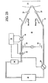
Fig. 1 , the present invention, in an embodiment, can be adapted to monitor access conditions during dialysis therapy. A patient is connected to adialysis system 10 via anextracorporcal blood circuit 12 that includes anarterial blood line 14 and avenous blood line 16 coupled to avascular access 18 of the patient via anarterial needle 20 and avenous needle 22 or other suitable access device as shown inFig. 1 . In this regard, blood can circulate into, through and out of the patient along theblood circuit 12 during dialysis therapy. - The
dialysis system 10 can include any number and variety of components. For example, the dialysis system includes anysuitable clamp 24 or other flow regulator, an air bubble trap or the like 26, ablood treatment device 28, such as a dialyzer and ablood pump 29, such as a peristaltic pump. The components can be coupled to the blood circuit as schematically shown inFig. 1 . Any one or combination of these components can be apart of a dialysis machine coupled to the blood circuit, as described below. During treatment, blood passes from the patient through thearterial blood line 14, into theblood treatment device 28 and circulates back into the patient along thevenous blood line 16. - As previously discussed, the present invention can include any suitable type of electrical circuit and design to effectively detect access disconnection during medical therapy. In an embodiment, the present invention includes a pair of induction coils attached to the
blood circuit 12 at separate locations. As shown inFig. 1 , afirst induction coil 30 is attached to thevenous blood line 16 and asecond induction coil 32 is attached to thearterial blood line 14. - It should be appreciated that any suitable type of induction coil can be utilized, such as a field coil coupled to and around the blood circuit. The induction coil can be attached to the fluid circuit in any suitable way. For example, the field coil can be wound around the fluid circuit. In an embodiment, the induction coil is placed around at least one member of a movable coupling device. The coupling device can be opened and closed allowing the induction coil to be readily and effectively placed around the fluid circuit as described below.
- In an embodiment, any suitable electric signal can be injected into the blood circuit. A level of current is generated with any
suitable device 34 and injected into the blood circuit at thefirst induction coil 30 attached to thevenous blood line 16. As the electric current passes through theblood circuit 12, thesecond coil 32 can measure a change in an electrical value due to changes in access conditions during dialysis therapy. A change in amperage, impedance or the like can be detected with high reliability in response to dislodgment of one or both of thevenous needle 22 andarterial needle 20 from the patient or other like devices. Alternatively, the electric current can be induced into the venous blood line and measured along the arterial blood line. As used herein, the term "electrical value" or other like terms means any suitable electrical parameter typically associated with electrical circuitry including, for example, impedance, resistance, voltage, current, rates of change thereof and combinations thereof. - The
induction coil 32 can be used to pass a signal based on the measurable change in amperage or the like due to changes in access conditions, such as needle or drop-out. The signal can then be detected and further processed by asignal processing unit 33 connected to theinduction coil 32. Thesignal processing unit 33 can then be coupled to any suitable component of the blood treatment system, such as theblood pump 29 and theclamp 24. In this regard, theblood pump 29 can be automatically shut off and/or theclamp 24 can be automatically closed to controllably minimize blood loss to the patient in response to, for example, needle-drop out or other suitable access disconnection conditions. - As shown in
Fig. 1 , the present invention includes aconductive connection 35 made between twocontact points 36 positioned along thearterial blood line 14 andvenous blood line 16. This forms aconductive pathway 38 thereby defining aconductor loop 40 that remains closed until access disconnection. This allows the electric signal passing therein to bypass one or more of the components of the dialysis system along the blood circuit. In an embodiment, theconductive connection 35 can be positioned allowing the conductive pathway to bypass all of the components of thedialysis system 10 as shown inFig. 1 . - The bypass effectively acts to reduce the high impedance effects of various components of the dialysis system, such as the
air bubble trap 26, theblood treatment device 28, theblood pump 29, the like and combinations thereof. In this regard, the injection of a high level of current or the like into the blood circuit is not required to overcome the high impedance effects of such components. This can facilitate the reliable detection of a change in impedance or other suitable electrical value in response to needle dislodgment. The use of high levels of current can necessarily result in a high level of noise which may impact detection sensitivity. Further, the ability to inject a lower level of an electrical signal, preferably current, in the blood circuit can better ensure the health and safety of the patient. - The
conductive connection 35 can be formed in any suitable way. In an embodiment, theconductive connection 35 includes theconductive path 38 in fluid contact with blood flowing through thearterial blood line 14 andvenous blood line 16 at the two contact points 36. Theconductive path 38 can be composed of any suitable conductive material, such as a wire or other like conductive material such that theconductive path 38 has an impedance that is less than the impedance of the component or components of thedialysis system 10 that are bypassed. The impedance of theconductive path 38 is less than the impedance of the components in an amount effective to cause the electric current to bypass the components, and thus follow the path of least resistance. Alternatively, theconductive connection 35 can be coupled to the venous and arterial blood lines with capacitive couplers and thus does not make fluid contact with the blood. -
Figs. 2A and2B show that three contact points can be positioned along theblood circuit 12. Thefirst contact point 42 includes an induction coil capable of inducing an electric current or the like into the blood circuit. It should be appreciated that the electrical current or other suitable signal can be injected into the blood circuit in any suitable way including using an induction coil (as previously discussed), a capacitive coupler, an electrical contact in fluid communication with the blood and the like. Thefirst contact point 42 is located on thevenous blood line 16 at a position before the components of the dialysis system (refer toFig. 1 ) along theblood circuit 12. Thesecond contact point 44 is located on thearterial blood line 14 at a position before the components of the dialysis system along theblood circuit 12. Alternatively, the first 42 and second 44 contacts can be located on thearterial blood line 14 and thevenous blood line 16, respectively. - The
third contact point 46 can be located at any suitable position between the first 42 andsecond contact 44 points along a portion of theblood circuit 12 that connects the first 42 and second 44 contact points to the components of the dialysis system as shown inFigs. 2A and2B . The second 44 and third 46 contact points form a direct conductive connection in theblood circuit 12. The direct connection between the second 44 and third 46 contact points can be made in any suitable way. For example, thesecond contact 44 and thethird contact 46 can be attached to theblood circuit 12 via an induction coil, an electrical contact in fluid contact with the blood, an electrical contact capacitively coupled to the blood circuit and/or the like as the fluid flows along theblood circuit 12. Any suitable device can be used to make an electrical connection with the fluid circuit, illustrative examples of which are described in detail below. - The electric signal is injected into the blood circuit through the
first contact point 42 in any suitable way, such as through an induction coil, thereby defining a conductor loop along the blood circuit. The conductive connection made directly between the second 44 and third 46 contact points can be utilized to measure a change in an electrical value in response to access disconnection as shown inFig. 2A . Alternatively, the electrical signal can be generated and injected through the direct conductive connection where thefirst contact point 42 is used to measure the a detectable change in the electrical value, such as impedance or the like as shown inFig. 2B . - The use of the direct connection between the second 44 and third 46 contact points can facilitate the reliable detection of access disconnection, such as needle or catheter dislodgment. In this regard, a lower level of current or the like can be used to for detection purposes. From a practical standpoint, it is believed that the use of the direct connection can be achieved without requiring extensive modifications to the blood circuit as previously discussed.
- The present invention provides a variety of different ways in which an electrical contact can be attached to a fluid circuit, such as a blood circuit, for use during detection of access detection. By way of example and not limitation, illustrative examples are described below.
- In an embodiment, the present invention includes an induction coil coupling device that can be more easily and effectively utilized to monitor vascular access during therapy. In an embodiment, the
coupling device 50 of the present invention includes afirst member 52 that is movably attached to asecond member 54 at afirst end 55 allowing displacement of thefirst member 52 and thesecond member 54 relative to one another. Thefirst member 52 and thesecond member 54 can be movable attached in any suitable manner. For example, ahinge 56 or any other suitable movable device can be used. A coiledmember 57, preferably aninduction coil 57, is wrapped around at least a portion of the coupling device. In an embodiment, the induction coil is wrapped around a portion of the firstmovable member 52 as shown inFigs. 3A and 3B . Alternatively theinduction coil 57 can be wrapped around the secondmovable member 54, both members and portions thereof. - In
Fig. 3A , theinduction coupling device 50 of the present invention is in an open configuration such that it can be readily placed around a fluid conduit (not shown), such as a blood line of a blood circuit. Next, thefirst member 52 and/or thesecond member 54 can be displaced to close and secure thecoupling device 50 to the blood line as shown inFig. 3B . In an embodiment, thefirst member 52 and thesecond member 54 can be displaced to matingly engage in any suitable way at a second end. This enables theinduction coupling device 50 to be easily attached to a blood circuit as compared to the mere use of an induction field coil which must necessarily be wound around the blood line of the blood circuit a multiple number of times for effective use. - In an embodiment, the movable members are composed of a material that has a high magnetic permeability, such as a ferrite bead. In the closed position, the movable members must meet in mating engagement. In this regard, the movable members can effect act to converge or direct an electromagnetic field through the
induction coil 57. This can enhance the electromagnetic flux through the induction coil allowing the induction coupling device to be effectively used to detect access disconnection as previously discussed. - In an embodiment, the present invention can include an electrical contact coupling device that can be utilized to secure the electrical contacts, preferably electrodes, to the blood circuit such that the electrodes effectively contact the blood and, thus, can be used to effectively monitor changes in access conditions as previously discussed. The coupling device of the present invention can also be designed to facilitate the protection of the user against contact with potential electrical sources. In an embodiment, the device can include a conductive element connected to a tube through which a medical fluid can flow wherein the conductive element has a first portion exposed to the medical fluid, such as blood, and a second portion external to the tube.
- It should be appreciated that the coupling device of the present invention can include a variety of different and suitable configurations, components, material make-up or the like. In an embodiment, the present invention can include a device for connecting an electrical contact to a fluid conduit providing fluid and electrical communication between the electrical contact and fluid flowing through the fluid conduit. The device can include a first member including an annular portion capable of accommodating the electrical contact and a first stem portion connected to the annular member wherein the stem portion has an opening extending therethrough to the annular portion; a second member including a base portion with a groove region and a second stem portion with an opening extending therethrough to the groove region allowing the first member to be inserted and secured to the second member; and a contact member adapted to fit the first and second stem portions allowing the contact member to abut against at least a portion of the electrical contact member allowing an electrical connection to be made between the electrical contact and the contact member.
- As illustrated in
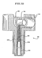
Figs. 3C and3D , the electricalcontact coupling device 80 includes aprobe member 82 that has a cylindrical shape with anopening 84 extending therethrough. In this regard, an electrical contact, preferably anelectrode 86 having a cylindrical shape can be inserted into theopening 84 such that theelectrode 86 is secure within theprobe member 82. In an embodiment, theprobe member 82 has achannel 85 extending along at least a portion of theopening 84 within which theelectrode 86 can be inserted into theprobe member 82. A tube member, for example, from a blood tubing set, connector tube member of a dialysis machine or the like, can be inserted into both ends of theopening 84 of theprobe member 82 in contact with an outer portion of thechannel 85 allowing blood or other suitable fluid to make fluid contact with theelectrode 86 in any suitable manner. Theelectrode 86 has anopening 88 that extends therethrough within which blood (not shown) or other suitable fluid from the fluid circuit can flow. In an embodiment, the diameter of theopening 88 of theelectrode 86 is sized to allow blood flow through theelectrode 86 such that blood flow levels under typical operating conditions, such as during dialysis therapy, can be suitably maintained. In this regard, the coupling device of the present invention can be readily and effectively attached to a fluid circuit, including a blood circuit or the like, for use during medical therapy including, for example, dialysis therapy. It should be appreciated that thecoupling device 80 of the present invention can be attached to the fluid circuit in any suitable way such that electrical and fluid connection can be made with the fluid flowing through the fluid circuit. - The
probe member 82 also includes astem portion 90 that extends from asurface 92 of its cylindrical-shaped body. Thestem portion 90 has anopening 93 that extends therethrough. In an embodiment, thestem portion 90 is positioned such that at least a portion of theelectrode 86 is in contact with theopening 93 of thestem portion 90. - In order to secure the
electrode 86 to the blood circuit, thecoupling device 80 includes asocket member 94 that includes abody portion 96 with anopening 98 for accepting theprobe member 82 and for accepting a blood tube member (not shown) of the blood circuit such that blood directly contacts the electrode as it circulates through the blood circuit during dialysis therapy. In an embodiment, thesocket member 94 includes astem portion 100 extending from thebody member 96 wherein thestem portion 100 includes anopening 102 extending therethrough. As theprobe member 82 is inserted through theopening 98 of thebody member 96, thestem portion 90 of theprobe member 82 can be inserted into theopening 102 of thestem portion 100 of thebody 96 of thesocket member 94. - In an embodiment, the
socket member 94 includes agroove region 104 extending along at least a portion of thebody 96 of thesocket member 94. In this regard, theprobe member 82 can be inserted through theopening 98 and then moved or positioned into thegroove region 104 to secure theprobe member 82 within thebody 96 of thesocket member 94. - In an embodiment, the
coupling device 80 includes anelectrical contact member 106 that is inserted within theopening 102 of thestem portion 100 of thebody 96 of thesocket member 94 such that theelectrical contact member 106 extends through theopening 93 of thestem portion 90 of theprobe member 82 to contact at least a portion of asurface 108 of theelectrode 86. - The
electrical contact member 106 is utilized to connect the electronics (not shown) of, for example, the excitation source, a signal processing device, other like electronic devices suitable for use in monitoring and/or controlling changes in access conditions, such as needle dislodgment. Theelectrical contact member 106 can be made of any suitable material, such as any suitable conductive material including, stainless steel, other like conductive materials or combinations thereof. In order to secure theelectrical contact member 106 in place, acontact retainer member 110 is inserted within theopening 102 of thestem portion 100 at anend region 112 thereof. - In an embodiment, the coupling device can be mounted to a dialysis machine, device or system in any suitable manner. For example, the coupling device can be mounted as an integral component of the dialysis machine. As well, the coupling device can be mounted as a separate and/or stand alone component which can interface with any of the components of the apparatus and system of the present invention. In an embodiment, the
coupling device 80 can be insertably mounted via thestem portion 100 of thesocket member 94 to a dialysis machine or other suitable components. - It should be appreciated that the electrical contact coupling device can include a variety of different and suitable shapes, sizes and material components. For example, another embodiment of the coupling device is illustrated in
Fig. 3E . Thecoupling device 114 inFig. 3E is similar in construction to the coupling device as shown inFigs. 3C and3D . In this regard, thecoupling device 114 ofFig. 3E can include, for example, a cylindrical-shaped electrode or other suitable electrical contact, a probe member for accepting the electrode and securing it in place within a socket member of the sensing device. The probe member includes a stem portion that is insertable within a stem portion of the socket member. An electrical contact member is insertable within the stem portion such that it can contact the electrode. The coupling device ofFig. 3E can also include a contact retainer member to hold the electrical contact member in place similar to the coupling device as shown inFigs. 3C and3D . - As shown in
Fig. 3E , theprobe member 116 of the electricalcontact coupling device 114 includes ahandle 118 which can facilitate securing theprobe member 116 within thesocket member 120. Thehandle 118, as shown, has a solid shape which can facilitate the use and manufacture of thecoupling device 114. In addition, the stem portion (not shown) of theprobe member 116 is larger in diameter than the stem portion of the probe member as illustrated inFig. 3C . By increasing the stem size, the probe member can be more easily and readily inserted within the socket member. Further, the probe member is greater in length as compared to the probe member as shown inFigs. 3C and3D such that theend regions 122 of theprobe member 116 extend beyond agroove region 124 of thesocket member 120. This can facilitate securing the probe member within thegroove region 124 of thesocket member 120. - In an embodiment, an
opening 126 of thesocket member 120 can include anadditional opening portion 128 to accommodate the insertion of the stem portion of theprobe member 116, having an increased size, therethrough. This can ensure proper alignment of the probe member with respect to the socket member before insertion of the probe member into the socket member thus facilitating the insertion process. - It should be appreciated that the probe member, socket member and contact retainer member can be composed of a variety of different and suitable materials including, for example, plastics, molded plastics, like materials or combinations thereof. The various components of the coupling device, such as the probe member, socket member and contact retainer member, can be fitted in any suitable way. For example, the components can be fitted in smooth engagement (as shown in
Figs. 3C and3D ), in threaded engagement (as shown inFigs. 3F and3G ) and/or any suitable fitting engagement or arrangement relative to one another. - As shown in
Figs. 3F and3G , thecoupling device 130 of the present invention can be made of threaded parts which are removably and insertably connected to one another to form the coupling device. The threaded parts can facilitate securing the electrode to the blood circuit as well as general use of same as described below. - In an embodiment, the
stem portion 132 of thebody 134 of thecoupling device 130 has a threadedregion 136 which can be insertably attached to a dialysis machine or other suitable mounting device in threaded engagement. This can facilitate the ease in which the coupling device is attached and detached from the mounting device. - As shown in
Fig. 3G , thestem portion 132 is threaded on both sides allowing it to be in threaded engagement with anannular member 138. Theannular member 138 provides direction and support allowing theelectrical contact member 140 to abut against theelectrode 142 housed in theprobe member 144 as previously discussed. - In an embodiment, a
plate member 146 made of any suitable conductive material can be depressed against aspring 148 as theprobe member 144 is secured to thebody 134. At the same time, anotherspring 150 can be displaced against theelectrical contact member 140 in contact with theretainer 152 which is inserted within an annular region of theannular member 138 to secure theelectrical contact member 140 to thebody 134. - The spring mechanism in an embodiment of the present invention allows the parts of the
coupling device 130 to remain in secure engagement during use. It can also facilitate use during detachment of the parts for cleaning, maintenance or other suitable purpose. - As previously discussed, the present invention can be effectively utilized to detect dislodgment of an access device, such as a needle or catheter, inserted within a patient through which fluid can pass between the patient and a fluid delivery and/or treatment system. The present invention can be applied in a number of different applications, such as medical therapies or treatments, particularly dialysis therapies. In dialysis therapies, access devices, such as needles or catheters, can be inserted into a patient's arteries and veins to connect blood flow to and from the dialysis machine.
- Under these circumstances, if the access device becomes dislodged or separated from the blood circuit, particularly the venous needle, the amount of blood loss from the patient can be significant and immediate. In this regard, the present invention can be utilized to controllably and effectively minimize blood loss from a patient due to dislodgment of the access device, such as during dialysis therapy including hemodialysis, hemofiltration, hemodiafiltration and continuous renal replacement.
- As previously discussed, the present invention can be adapted for use with any suitable fluid delivery system, treatment system or the like. In an embodiment, the present invention is adapted for use with a dialysis machine to detect access disconnection as blood flows between the patient and the dialysis machine along a blood circuit during treatment, including, for example hemodialysis, hemofiltration and hemodiafiltration.
- The present invention can include any suitable dialysis machine for such purposes. An example, of a hemodialysis machine of the present invention is disclosed in
U.S. Patent No. 6,143,181 . In an embodiment, thedialysis machine 190 comprises amobile chassis 192 and it has at thefront side 194 thereof acommon mechanism 196 for connecting tubing or the like by which a patient can be connected to the dialysis machine as shown inFig. 4B . Aflat touch screen 197 which can show several operational parameters and is provided with symbols and fields for adjustment of the dialysis machine by relevant symbols and fields, respectively, on the screen being touched can be adjusted vertically and can be universally pivoted on the dialysis machine and can be fixed in the desired adjusted position. - In an embodiment, the dialysis machine includes a chassis having one or more connectors for connecting a patient to the dialysis machine via a blood circuit allowing blood to flow between the patient and the dialysis machine during dialysis therapy wherein one or more electrical contacts are connected to the blood circuit in fluid communication with the blood allowing detection of a change in an electrical value in response to access disconnection as the blood flows through the blood circuit having an electrical signal passing therein as previously discussed.
- In an embodiment, the dialysis machine of the present invention can be designed to accommodate one or more of the coupling devices, such as an induction coil coupling device and other such coupling devices as previously discussed, used to detect access disconnection as shown in
Fig. 4B . For example, one ormore coupling devices 198 can be attached to thefront panel 194 of thedialysis machine 190. This can be done in any suitable way. In an embodiment, a stem portion of the coupling device is insertably mounted via a threaded fit, frictional fit or the like, as previously discussed. This connects the patient to thedialysis machine 190 via a blood tubing set 202. The blood tubing set includes afirst blood line 204 and asecond blood line 206. In an embodiment, thefirst blood line 204 is connected to the patient via anarterial needle 208 or the like through which blood can flow from thepatient 200 to thedialysis machine 190. Thesecond blood line 206 is then connected to thepatient 200 via avenous needle 210 or the like through which fluid flows from the dialysis machine to the patient thereby defining a blood circuit. Alternatively, the first blood line and the second blood line can be coupled to the venous needle and the arterial needle, respectively. The blood lines are made from any suitable medical grade material. In this regard, access disconnection, such as dislodgment of an arterial needle and/or a venous needle can be detected as previously discussed. Alternatively, the coupling device can be attached to the blood tubing set which is then attached to the dialysis machine in any suitable way. - As previously discussed, the present invention can be used during dialysis therapy conducted at home and in dialysis treatment centers. The dialysis treatment centers can provide dialysis therapy to a number of patients. In this regard, the treatment centers include a number of dialysis machines to accommodate patient demands. The therapy sessions at dialysis treatment centers can be performed 24 hours a day, seven days a week depending on the locale and the patient demand for use.
- In an embodiment, the dialysis treatment centers are provided with the capability to detect access disconnection during dialysis therapy pursuant to an embodiment of the present invention. For example, one or more of the dialysis machines within the center can be adapted for use with an electrical contact coupling, induction coil coupling device and/or the like along with other components necessary to detect access disconnection as previously discussed.
- In an embodiment, the coupling device can be directly attached to one or more of the dialysis machines of the dialysis treatment center. It should be appreciated that the apparatuses, pursuant to an embodiment of the present invention can be applied for use during dialysis therapy administered to one or more patients in the dialysis treatment center in any suitable way. In an embodiment, the treatment center can have one or more patient stations at which dialysis therapy can be performed on one or more patients each coupled to a respective dialysis machine. Any suitable in-center therapy can be performed including, for example, - hemodialysis, hemofiltration, hemodiafiltration, continuous renal replacement and combinations thereof. As used herein, the term "patient station" or other like terms mean any suitably defmed area of the dialysis treatment center dedicated for use during dialysis therapy. The patient station can include any number and type of suitable equipment necessary to administer dialysis therapy.
- In an embodiment, the dialysis treatment center includes a number of patient stations each at which dialysis therapy can be administered to one or more patients; and one or more dialysis machines located at a respective patient station. One or more of the dialysis machines can include a chassis having one or more connectors for connecting a patient to the dialysis machine via a blood circuit allowing blood to flow between the patient and the dialysis machine during dialysis therapy wherein a number of electrical contacts can be connected to the blood circuit in fluid communication with the blood allowing detection of a change in an electrical value in response to access disconnection as the blood flows through the blood circuit having an electrical signal passing therein.
- As previously discussed, the access disconnection detection capabilities of the present invention can be utilized to monitor and control a safe and effective dialysis therapy. Upon dislodgment of an access device, such as a needle or catheter, from the patient, the access disconnection detection capabilities of the present invention can be used to provide a signal indicative of dislodgment that can be further processed for control and/or monitoring purposes. In an embodiment, the signal can be further processed to automatically terminate dialysis therapy to minimize blood loss due to dislodgment as previously discussed. Further, the signal can be processed to activate an alarm which can alert the patient and/or medical personnel to the dislodgment condition to ensure that responsive measures are taken. It should be appreciated that the present invention can be modified in a variety of suitable ways to facilitate the safe and effective administration of medical therapy, including dialysis therapy.
- It should be understood that various changes and modifications to the presently preferred embodiments described herein will be apparent to those skilled in the art. Such changes and modifications can be made without departing from the scope of the present invention and without diminishing its intended advantages. It is therefore intended that such changes and modifications be covered by the appended claims.
- Preferred aspects of the invention are described in the following numbered paragraphs of the description.
- 1. A method of detecting access disconnection during an extracorporeal blood treatment, the method comprising the steps of:
- coupling an extracorporeal blood system including a plurality of components to a patient with an extracorporeal blood circuit including a first blood line and a second blood line such that blood flows into, through and out of the patient along the extracorporeal blood circuit during treatment;
- injecting an electrical signal into the extracorporeal blood circuit;
- passing the electrical signal through a conductive connection between the first blood line and the second blood line thereby defining a loop that bypasses one or more components of the extracorporeal blood system coupled to the extracorporeal blood circuit; and
- measuring a change in an electrical value in response to access disconnection.
- 2. The method of
paragraph 1 wherein an electrical current is injected into the blood circuit. - 3. The method of
paragraph 1 wherein the change in the electrical value is measured in response to dislodgment of a needle in the patient that is coupled to a venous blood line. - 4. The method of
paragraph 1 wherein the change in the electrical value is measured in response to dislodgement of a needle in the patient that is coupled to an arterial blood line. - 5. The method of
paragraph 1 wherein the conductive connection includes a conductive material which defines a conductive path between the first blood line and the second blood line. - 6. The method of paragraph 5 wherein the conductive connection is adapted to contact blood flowing through the first and second blood lines.
- 7. The method of paragraph 5 wherein the conductive connection is capacitively coupled to the first and second blood lines.
- 8. The method of
paragraph 1 wherein the bypassed components are selected from the group consisting of a bubble trap, a blood pump, a blood treatment device, a dialysis machine and combinations thereof. - 9. The method of
paragraph 1 wherein the electrical value is selected from the group consisting of voltage, resistance, impedance, current, rates of changes thereof and combinations thereof. - 10. An apparatus for detecting dislodgment of an access device inserted within a patient as blood flows through an extracorporeal blood circuit including a first blood line and a second blood line that connects the patient to an extracorporeal blood system including a plurality of components, the apparatus comprising:
- an electrical signal device for injecting an electrical signal into the extracorporeal blood circuit;
- a bypass device that includes a conductive connection between the first blood line and the second blood line thereby defining a loop along the extracorporeal blood circuit allowing the electrical signal to bypass one or more components of the extracorporeal blood system; and
- a measuring device coupled to the extracorporeal blood circuit that is capable of measuring a change in an electrical value in response to dislodgment of the access device.
- 11. The apparatus of
paragraph 10 wherein the electrical signal device comprises an induction coil. - 12. The apparatus of
paragraph 10 wherein the electrical signal device is capacitively coupled to the blood circuit. - 13. The apparatus of
paragraph 10 wherein the electrical signal device comprises an electrical contact in fluid and electrical communication with blood flowing through the blood circuit. - 14. The apparatus of
paragraph 10 further comprising an analyzer unit coupled to the measuring device that is capable of processing a signal derived from the measuring device allowing the change in electrical value to be detected and further processed. - 15. The apparatus of
paragraph 10 wherein the change in the electrical value is detected in response to dislodgment of a needle in the patient. - 16. The apparatus of
paragraph 10 wherein the conductive connection includes a conductive path in direct contact with blood flowing in the first and second blood lines. - 17. The apparatus of
paragraph 10 wherein the conductive connection is capacitively coupled to the first and second blood lines. - 18. The apparatus of
paragraph 10 wherein the measuring device includes an induction coil. - 19. A method of detecting access disconnection during an extracorporeal blood treatment, the method comprising the steps of:
- coupling an extracorporeal blood system including a plurality of components to a patient via an extracorporeal blood circuit including a first blood line and a second blood line allowing blood to flow into, through and out of the patient along the extracorporeal blood circuit during treatment;
- injecting an electrical signal into the blood circuit through a direct conductive connection between a first contact point and a second contact point attached to the extracorporeal blood circuit and directly contacting the blood thereby defining a loop; and measuring a change in an electrical value at a third contact point attached to the extracorporeal blood circuit in response to access disconnection.
- 20. The method of paragraph 19 wherein the direct conductive connection is formed between a pair of electrodes in direct contact with blood as it flows through the extracorporeal blood circuit.
- 21. The method of paragraph 19 wherein an induction coil is coupled to the extracorporeal blood circuit at the third contact point allowing the change in the electrical value to be measured.
- 22. The method of paragraph 19 wherein the third contact point includes an electrical contact attached to the blood circuit in fluid communication with the blood.
- 23. The method of paragraph 19 wherein the third contact point includes a capacitive coupler.
- 24. The method of paragraph 19 wherein the electrical value is selected from the group consisting of voltage, resistance, impedance, current, rate of changes thereof and combinations thereof.
- 25. The method of paragraph 19 wherein the change in electrical value is measured in response to dislodgment of a needle in the patient that is coupled to the extracorporeal blood circuit.
- 26. An apparatus for detecting dislodgment of an access device from a patient as blood flows through an extracorporeal blood circuit including a first blood line and a second blood line allowing connection of the patient to an extracorporeal blood system including a plurality of components, the apparatus comprising:
- a direct conductive connection between a first contact point and a second contact point attached to the extracorporeal blood circuit through which an electrical signal can be injected into the blood circuit thereby defining a loop; and
- a measuring device coupled to the extracorporeal blood circuit at a third contact point wherein the measuring device can be used to measure a change in an electrical value in response to dislodgment detection.
- 27. The apparatus of
paragraph 26 wherein the direct conductive connection is formed between a pair of electrodes in direct contact with blood as it flows through the extracorporeal blood circuit. - 28. The apparatus of
paragraph 26 wherein an induction coil is coupled to the extracorporeal blood circuit at the third contact point allowing the change in the electrical value to be measured. - 29. The apparatus of
paragraph 26 wherein the third contact point includes an electrical contact attached to the blood circuit in fluid communication with the blood. - 30. The apparatus of
paragraph 26 wherein the third contact point includes a capacitive coupler attached to the blood circuit. - 31. The apparatus of
paragraph 26 wherein the electrical value is selected from the group consisting of voltage, resistance, impedance, current, rate of changes thereof and combinations thereof. - 32. The apparatus of
paragraph 26 wherein a change in impedance is detected in response to dislodgment of a needle in the patient that is coupled to the extracorporeal blood circuit. - 33. A method of detecting access disconnection during an extracorporeal blood treatment, the method comprising the steps of:
- coupling an extracorporeal blood system including a plurality of components to a patient via an extracorporeal blood circuit including a first blood line and a second blood line allowing blood to flow into, through and from the patient along the extracorporeal blood circuit during treatment;
- injecting an electrical signal into the blood circuit at a first contact point thereby defining a loop; and
- measuring a change in an electrical value using a direct conductive connection made between a second electrical contact point and a third electrical contact point along the loop in response to access disconnection.
- 34. The method of
paragraph 33 wherein the direct conductive connection is formed between a pair of electrodes in direct contact with blood as it flows through the extracorporeal blood circuit. - 35. The method of
paragraph 33 wherein an induction coil is coupled to the extracorporeal blood circuit at the first contact point allowing the electric signal to be injected. - 36. The method of
paragraph 33 wherein the third contact point includes an electrical contact attached to the blood circuit in fluid communication with the blood. - 37. The method of
paragraph 33 wherein the third contact point includes a capacitive coupler attached to the blood circuit. - 38. The method of
paragraph 33 wherein the electrical value is selected from the group consisting of voltage, resistance, impedance, current, rate of changes thereof and combinations thereof. - 39. The method of
paragraph 33 wherein the change in electrical value is measured in response to dislodgment of a needle in the patient that is coupled to the extracorporeal blood circuit allowing blood to flow into, through and out of the patient. - 40. An apparatus for detecting dislodgment of an access device from a patient as blood flows through an extracorporeal blood circuit which includes a first blood line and a second blood line allowing connection of the patient to an extracorporeal blood system including a plurality of components, the apparatus comprising:
- an electrical signal device coupled to the extracorporeal blood circuit at a first contact point capable of injecting an electrical signal into the blood circuit thereby defining a loop; and
- a direct conductive connection between a second contact point and a third contact point within the loop along which a change in an electrical value can be measured in response to dislodgment.
- 41. The apparatus of
paragraph 40 wherein the direct conductive connection includes a pair of electrodes in direct contact with blood as it flows through the extracorporeal blood circuit. - 42. The apparatus of
paragraph 40 wherein an induction coil is coupled to the extracorporeal blood circuit at the third contact point. - 43. The method of
paragraph 40 wherein the third contact point includes an electrical contact attached to the blood circuit in fluid communication with the blood. - 44. The method of
paragraph 40 wherein the third contact point includes a capacitive coupler. - 45. The method of
paragraph 40 wherein the electrical value is selected from the group consisting of voltage, resistance, impedance, current, rate of changes thereof and combinations thereof. - 46. The apparatus of
paragraph 40 wherein the change in an electrical value is measured in response to dislodgment of a needle in the patient and coupled to the extracorporeal blood circuit. - 47. A dialysis machine comprising a chassis having one or more connectors for connecting a patient to the dialysis machine via a blood circuit allowing blood to flow between the patient and the dialysis machine during dialysis therapy wherein a plurality of electrical contacts are connected to the blood circuit allowing detection of access disconnection using a direct conductive connection.
- 48. The dialysis machine of paragraph 47 wherein the direct conductive connection can be used to inject an electrical signal into the blood circuit thereby defining a loop allowing detection of access disconnection.
- 49. The dialysis machine of paragraph 48 wherein the direct conductive connection can be used to measure a change in an electrical value in response to access disconnection.
- 50. The dialysis machine of paragraph 48 wherein the direct conductive connection can be used to bypass the dialysis machine from the loop.
- 51. The dialysis machine of paragraph 47 wherein the direct conductive connection is made between a pair of electrical contacts in direct contact with blood as it flows through the blood circuit.
- 52. The dialysis machine of paragraph 47 wherein a controller is attached to at least one of the electrical contacts allowing processing of a signal indicative of a detectable change in an electrical value in response to access disconnection such that blood loss due to same can be minimized.
- 53. The dialysis machine of
paragraph 52 wherein the signal can be processed allowing automatic termination of dialysis therapy. - 54. The dialysis machine of paragraph 47 wherein the access disconnection is due to dislodgment of an access device inserted in the patient through which blood can flow along the blood circuit.
- 55. The dialysis machine of
paragraph 54 wherein the access device is selected from the group consisting of a needle, a catheter, a venous needle and an arterial needle. - 56. The dialysis machine of paragraph 47 wherein the electrical contacts are attached to the chassis of the dialysis machine.
- 57. A dialysis treatment center comprising:
- a plurality of patient stations each at which dialysis therapy can be administered; and
- one or more dialysis machines located at a respective patient station, at least one of the dialysis machines including a chassis having one or more connectors for connecting a patient to the dialysis machine via a blood circuit allowing blood to flow between the patient and the dialysis machine during dialysis therapy wherein a plurality of electrical contacts are connected to the blood circuit allowing detection of access disconnection using a direct conductive connection.
- 58. The dialysis treatment center of
paragraph 57 wherein the direct conductive connection can be used to inject an electrical signal into the blood circuit thereby defining a loop allowing detection of access disconnection. - 59. The dialysis treatment center of paragraph 58 wherein the direct conductive connection can be used to measure a change in an electrical value in response to access disconnection.
- 60. The dialysis treatment center of paragraph 58 wherein the direct conductive connection can be used to bypass the dialysis machine from the loop.
- 61. The dialysis treatment center of
paragraph 57 wherein the direct conductive connection is made between a pair of electrical contacts in direct contact with blood as it flows through the blood circuit. - 62. The dialysis treatment center of
paragraph 57 wherein a controller is attached to at least one of the electrical contacts allowing processing of a signal indicative of a detectable change in an electrical value in response to access disconnection such that blood loss due to same can be minimized. - 63. The dialysis treatment center of paragraph 62 wherein the signal can be processed allowing automatic termination of dialysis therapy.
- 64. The dialysis treatment center of paragraph 62 wherein the signal can be processed to activate an alarm upon detection of access disconnection.
- 65. The dialysis treatment center of paragraph 62 wherein the patient and/or medical staff can be alerted to take responsive actions in response to the alarm.
- 66. The dialysis treatment center of
paragraph 57 wherein the dialysis therapy is selected from the group consisting of hemodialysis, hemofiltration, hemodiafiltration and continuous renal replacement. - 67. The dialysis treatment center of
paragraph 57 wherein the access disconnection is due to dislodgment of an access device inserted in the patient through which blood can flow. - 68. The dialysis treatment center of paragraph 67 wherein the access device is selected from the group consisting of a needle, a catheter, a venous needle and an arterial needle.
- 69. An inductive coupling device comprising:
- a first member and a second member movably attached to the first member at an end allowing for displacement of the first member and the second member into an open arrangement and a closed arrangement; and
- an induction coil placed around at least a portion of at least one of the first and second members.
- 70. The inductive coupling device of paragraph 69 wherein the inductive coupling device includes a hinge attached to the first member and the second member at the end.
- 71. The inductive coupling device of paragraph 69 wherein the first and second members are composed of a material that has a magnetic permeability in an amount effective to converge an electromagnetic field into the induction coil.
- 72. A method for injecting an electrical signal in a fluid passing through a fluid conduit, the method comprising the steps of:
- providing an inductive coupler including a first member and a second member movably attached to the first member at an end allowing for displacement of the first member and the second member into an open arrangement and a closed arrangement wherein an induction coil is attached to the inductive coupler;
- placing the inductive coupler around the fluid conduit in the open arrangement;
- displacing the first member and the second member to the closed arrangement thereby securing the inductive coupler to the fluid conduit; and
- using the inductive coupler to inject an electrical signal in the fluid.
- 73. The method of paragraph 72 wherein a hinge is used to movably attach the first member to the second member.
- 74. The method of paragraph 72 wherein the first and second members can direct an electromagnetic field to the induction coil allowing injection of the electrical signal.
- 75. The method of paragraph 72 wherein the fluid comprises blood passing through an extracorporeal blood circuit connecting a patient to an extracorporeal blood system.
- 76. The method of paragraph 72 wherein the electrical signal comprises a current.
- 77. A method for detecting a change in an electrical value as fluid passes through a fluid conduit of a fluid circuit, the method comprising the steps of:
- providing a coupling device including a first member and a second member movably attached to the first member at a first end allowing for displacement of the first member and the second member into an open arrangement and a closed arrangement wherein an induction coil is attached to the coupling device;
- placing the coupling device with the induction coil around the fluid conduit in the open arrangement;
- displacing the first member and the second member to the closed arrangement thereby securing the induction coil to the fluid conduit; and
- using the induction coil to measure the change in electrical value as the fluid passes through the fluid conduit with an electrical signal passing therein.
- 78. The method of paragraph 77 wherein a hinge is used to movably attach the first member to the second member.
- 79. The method of paragraph 77 wherein the coupling device can direct an electromagnetic field to the induction coil allowing measurement of a change in the electrical value.
- 80. The method of paragraph 77 wherein the fluid comprises blood passing through an extracorporeal blood circuit that couples a patient to an extracorporeal blood system.
Claims (35)
- An apparatus for detecting dislodgement of an access device inserted within a patient as blood flows through an extracorporeal blood circuit (12) including a first blood line (14) and a second blood line (16) that connects the patient to an extracorporeal blood system including a plurality of components (24, 26, 28, 29), the apparatus comprising:an electrical signal device (34) for injecting an electrical signal into the extracorporeal blood circuit;a bypass device that includes a conductive connection (35) between the first blood line (14) and the second blood line (16), the bypass device configured to establish a loop (40) along the extracorporeal blood circuit (12) to communicate the electrical signal and to bypass one or more components (24, 26, 28, 29) of the extracorporeal blood system; anda measuring device coupled to the extracorporeal blood circuit (12) that is capable of measuring a change in an electrical value in response to dislodgement of the access device;characterised in that the bypass device is separate from the electrical signal device and the measuring device.
- The apparatus of Claim 1, wherein the electrical signal device (34) comprises an induction coil (30).
- The apparatus of Claim 1, wherein the electrical signal device (34) is capacitively coupled to the blood circuit (12).
- The apparatus of Claim 1, wherein the electrical signal device (34) comprises an electrical contact in fluid and electrical communication with blood flowing through the blood circuit (12).
- The apparatus of Claim 1, further comprising an analyzer unit (33) coupled to the measuring device that is capable of processing a signal derived from the measuring device allowing the change in electrical value to be detected and further processed.
- The apparatus of Claim 1, wherein the change in the electrical value is detected in response to dislodgement of a needle in the patient.
- The apparatus of Claim 1, wherein the conductive connection (35) includes a conductive path (38) in direct contact with blood flowing in the first and second blood lines (14, 16).
- The apparatus of Claim 1, wherein the conductive connection (35) is capacitively coupled to the first and second blood lines (14, 16).
- The apparatus of Claim 1, wherein the measuring device includes an induction coil (32).
- The apparatus of Claim 1, wherein the measuring device is an inductive coupling device (50) comprising:a first member (52) and a second member (54) movably attached to the first member at an end (55) allowing for displacement of the first member (52) and the second member (54) into an open arrangement and a closed arrangement; andan induction coil (57) placed around at least a portion of at least one of the first and second members (52, 54).
- The apparatus of Claim 10, wherein the inductive coupling device includes a hinge (56) attached to the first member (52) and the second member (54) at the end (55).
- The apparatus of Claim 10, wherein the first and second members (52, 54) are composed of a material that has a magnetic permeability in an amount effective to converge an electromagnetic field into the induction col. (57).
- The apparatus of Claim 1, wherein the conductive connection (35) is a direct conductive connection between a first contact point and a second contact point attached to the blood circuit (12), and wherein the measuring device is coupled to the extracorporeal blood circuit at a third contact point such that the measuring device can be used to measure a change in an electrical value in response to dislodgement detection.
- The apparatus of Claim 13, wherein the direct conductive connection (35) is formed between a pair of electrodes in direct contact with blood as it flows through the extracorporeal blood circuit (12).
- The apparatus of Claim 13, wherein the electrical signal device is an induction coil coupled to the extracorporeal blood circuit (12) at the third contact point that allows the change in the electrical value to be measured.
- The apparatus of Claim 13, wherein the third contact point includes a capacitive coupler attached to the blood circuit (12).
- The apparatus of Claim 13, wherein a change in impedance is detected in response to dislodgement of a needle in the patient that is coupled to the extracorporeal blood circuit.
- The apparatus of Claim 1, wherein the electrical signal device (34) couples to the extracorporeal blood circuit (12) at a first contact point capable of injecting an electrical signal into the blood circuit (12) thereby defining a loop; and
a direct conductive connection (35) between a second contact point and a third contact point (40) within the loop such that the change in the electrical value can be measured in response to dislodgement. - The apparatus of Claim 18, wherein the direct conductive connection (35) includes a pair of electrodes in direct contact with blood as it flows through the extracorporeal blood circuit (12).
- The apparatus of Claim 18, wherein an induction coil is coupled to the extracorporeal blood circuit at the third contact point.
- The apparatus of Claim 13 or Claim 18, wherein the third contact point includes an electrical contact attached to the blood circuit (12) in fluid communication with the blood.
- The apparatus of Claim 18, wherein the third contact point includes a capacitive coupler.
- The apparatus of Claim 1, further comprising a dialysis machine (190) comprising a chassis (192) having one or more connectors for conrecting a patient to the dialysis machine via the extracorporeal blood circuit (12) to allow blood to flow between the patient and the dialysis machine (190) during dialysis therapy.
- The apparatus of Claim 1, wherein the bypass device is configured to bypass all of the components (24, 26, 28, 29) of the extracorporeal blood system.
- The apparatus of Claim 1, wherein the bypass device is used to reduce the high impedance effect of a blood pump (29) in the extracorporeal blood system.
- The apparatus of Claim 23, wherein the conductive connection (35) is made between a pair of electrical contacts in direct contact with blood as it flows through the extracorporeal blood circuit (12).
- The apparatus of Claim 26, wherein a controller (33) is electrically coupled to at least one of the electrical contacts and configured to process the electrical a signal indicative of the detectable change in the electrical value in response to access disconnection such that blood loss due to same can be minimised.
- The apparatus of Claim 27, wherein the controller (33) is configured to process the electrical signal automatically to terminate the dialysis therapy in response to dislodgement.
- The apparatus of Claim 23, wherein the access disconnection is due to dislodgement of an access device inserted in the patient through which blood can flow along the blood circuit (12).
- The apparatus of Claim 29, wherein the access device is selected from the group consisting of a needle, a catheter, a venous needle and an arterial needle
- The apparatus of Claim 26, wherein the electrical contacts are attached to the chassis (192) of the dialysis machine (190).
- The apparatus of Claim 23 further comprising a dialysis treatment centre including:a plurality of patient stations each at which dialysis therapy can be administered; andone or more dialysis machines (190) according to any of Claims 23 or 26 to 31 located at a respective patient station.
- The apparatus of Claim 32, wherein the signal can be processed to activate an alarm upon detection of access disconnection.
- The apparatus of Claim 33, wherein the patient and/or medical staff can be alerted to take responsive actions in response to the alarm.
- The apparatus of Claim 32, wherein the dialysis therapy is selected from the group consisting of haemodialysis, haemofiltration, heamodiafiltration and continuous renal replacement.
Applications Claiming Priority (2)
| Application Number | Priority Date | Filing Date | Title |
|---|---|---|---|
| US10/120,684 US7052480B2 (en) | 2002-04-10 | 2002-04-10 | Access disconnection systems and methods |
| EP03723889.6A EP1494736B1 (en) | 2002-04-10 | 2003-04-02 | Access disconnection methods |
Related Parent Applications (2)
| Application Number | Title | Priority Date | Filing Date |
|---|---|---|---|
| EP03723889.6 Division | 2003-04-02 | ||
| EP03723889.6A Division-Into EP1494736B1 (en) | 2002-04-10 | 2003-04-02 | Access disconnection methods |
Publications (3)
| Publication Number | Publication Date |
|---|---|
| EP2255840A2 EP2255840A2 (en) | 2010-12-01 |
| EP2255840A3 EP2255840A3 (en) | 2011-05-04 |
| EP2255840B1 true EP2255840B1 (en) | 2014-01-01 |
Family
ID=28790139
Family Applications (3)
| Application Number | Title | Priority Date | Filing Date |
|---|---|---|---|
| EP10075427.4A Expired - Fee Related EP2255840B1 (en) | 2002-04-10 | 2003-04-02 | System for detecting patient access disconnection |
| EP03723889.6A Expired - Lifetime EP1494736B1 (en) | 2002-04-10 | 2003-04-02 | Access disconnection methods |
| EP10075380.5A Expired - Lifetime EP2253344B1 (en) | 2002-04-10 | 2003-04-02 | Access disconnection systems |
Family Applications After (2)
| Application Number | Title | Priority Date | Filing Date |
|---|---|---|---|
| EP03723889.6A Expired - Lifetime EP1494736B1 (en) | 2002-04-10 | 2003-04-02 | Access disconnection methods |
| EP10075380.5A Expired - Lifetime EP2253344B1 (en) | 2002-04-10 | 2003-04-02 | Access disconnection systems |
Country Status (7)
| Country | Link |
|---|---|
| US (5) | US7052480B2 (en) |
| EP (3) | EP2255840B1 (en) |
| JP (3) | JP4503297B2 (en) |
| AU (1) | AU2003230794A1 (en) |
| MX (1) | MXPA04009849A (en) |
| TW (1) | TWI311059B (en) |
| WO (1) | WO2003086504A2 (en) |
Families Citing this family (93)
| Publication number | Priority date | Publication date | Assignee | Title |
|---|---|---|---|---|
| US7022098B2 (en) | 2002-04-10 | 2006-04-04 | Baxter International Inc. | Access disconnection systems and methods |
| US10155082B2 (en) | 2002-04-10 | 2018-12-18 | Baxter International Inc. | Enhanced signal detection for access disconnection systems |
| US20040254513A1 (en) | 2002-04-10 | 2004-12-16 | Sherwin Shang | Conductive polymer materials and applications thereof including monitoring and providing effective therapy |
| US7052480B2 (en) * | 2002-04-10 | 2006-05-30 | Baxter International Inc. | Access disconnection systems and methods |
| US7023313B2 (en) * | 2003-07-16 | 2006-04-04 | Marvell World Trade Ltd. | Power inductor with reduced DC current saturation |
| US7489219B2 (en) * | 2003-07-16 | 2009-02-10 | Marvell World Trade Ltd. | Power inductor with reduced DC current saturation |
| US7307502B2 (en) * | 2003-07-16 | 2007-12-11 | Marvell World Trade Ltd. | Power inductor with reduced DC current saturation |
| US7760525B2 (en) * | 2003-08-21 | 2010-07-20 | Marvell World Trade Ltd. | Voltage regulator |
| US7872454B2 (en) * | 2003-08-21 | 2011-01-18 | Marvell World Trade Ltd. | Digital low dropout regulator |
| US8029454B2 (en) | 2003-11-05 | 2011-10-04 | Baxter International Inc. | High convection home hemodialysis/hemofiltration and sorbent system |
| US8324872B2 (en) * | 2004-03-26 | 2012-12-04 | Marvell World Trade, Ltd. | Voltage regulator with coupled inductors having high coefficient of coupling |
| US7190152B2 (en) * | 2004-07-13 | 2007-03-13 | Marvell World Trade Ltd. | Closed-loop digital control system for a DC/DC converter |
| US20070004996A1 (en) * | 2005-06-20 | 2007-01-04 | Lovejoy David A | Needle disengagement sensing mechanism |
| US10537671B2 (en) | 2006-04-14 | 2020-01-21 | Deka Products Limited Partnership | Automated control mechanisms in a hemodialysis apparatus |
| CA2970214C (en) | 2006-04-14 | 2021-08-17 | Deka Products Limited Partnership | System for pumping a biological fluid |
| DE102006042646B4 (en) | 2006-09-12 | 2008-11-20 | Fresenius Medical Care Deutschland Gmbh | Device and method for monitoring access to a patient, in particular a vascular access in an extracorporeal blood treatment |
| US8152786B2 (en) * | 2006-11-07 | 2012-04-10 | Osprey Medical, Inc. | Collection catheter and kit |
| US8152751B2 (en) | 2007-02-09 | 2012-04-10 | Baxter International Inc. | Acoustic access disconnection systems and methods |
| US10463778B2 (en) | 2007-02-09 | 2019-11-05 | Baxter International Inc. | Blood treatment machine having electrical heartbeat analysis |
| US8376978B2 (en) * | 2007-02-09 | 2013-02-19 | Baxter International Inc. | Optical access disconnection systems and methods |
| US8357298B2 (en) | 2007-02-27 | 2013-01-22 | Deka Products Limited Partnership | Hemodialysis systems and methods |
| US9028691B2 (en) | 2007-02-27 | 2015-05-12 | Deka Products Limited Partnership | Blood circuit assembly for a hemodialysis system |
| KR20230165373A (en) | 2007-02-27 | 2023-12-05 | 데카 프로덕츠 리미티드 파트너쉽 | Hemodialysis system |
| US20090107335A1 (en) * | 2007-02-27 | 2009-04-30 | Deka Products Limited Partnership | Air trap for a medical infusion device |
| US8491184B2 (en) | 2007-02-27 | 2013-07-23 | Deka Products Limited Partnership | Sensor apparatus systems, devices and methods |
| US8393690B2 (en) * | 2007-02-27 | 2013-03-12 | Deka Products Limited Partnership | Enclosure for a portable hemodialysis system |
| US8425471B2 (en) | 2007-02-27 | 2013-04-23 | Deka Products Limited Partnership | Reagent supply for a hemodialysis system |
| US8042563B2 (en) | 2007-02-27 | 2011-10-25 | Deka Products Limited Partnership | Cassette system integrated apparatus |
| US8409441B2 (en) | 2007-02-27 | 2013-04-02 | Deka Products Limited Partnership | Blood treatment systems and methods |
| US8888470B2 (en) | 2007-02-27 | 2014-11-18 | Deka Products Limited Partnership | Pumping cassette |
| US9517295B2 (en) | 2007-02-27 | 2016-12-13 | Deka Products Limited Partnership | Blood treatment systems and methods |
| US8562834B2 (en) | 2007-02-27 | 2013-10-22 | Deka Products Limited Partnership | Modular assembly for a portable hemodialysis system |
| GB2448374A (en) * | 2007-04-14 | 2008-10-15 | Peter Lynton Howard | Clamping mechanism for dialysis tubing |
| US8287724B2 (en) * | 2007-07-05 | 2012-10-16 | Baxter International Inc. | Dialysis fluid measurement systems using conductive contacts |
| US20090007642A1 (en) * | 2007-07-05 | 2009-01-08 | Baxter International Inc. | Dialysis fluid measurement method and apparatus using conductive contacts |
| US8221320B2 (en) * | 2007-09-21 | 2012-07-17 | Baxter International Inc. | Access disconnect detection system |
| US7755488B2 (en) * | 2007-09-21 | 2010-07-13 | Baxter International Inc. | Access disconnection detection system |
| US8187184B2 (en) * | 2007-09-21 | 2012-05-29 | Baxter International, Inc. | Access disconnect system with optical and other sensors |
| EP2246080B1 (en) * | 2007-10-12 | 2016-02-10 | DEKA Products Limited Partnership | An extracorporeal blood flow system |
| CA2717886C (en) | 2008-04-01 | 2015-02-10 | Gambro Lundia Ab | An apparatus and a method for monitoring a vascular access |
| US8192388B2 (en) | 2008-07-25 | 2012-06-05 | Baxter International Inc. | System and method for detecting access disconnection |
| US8114043B2 (en) * | 2008-07-25 | 2012-02-14 | Baxter International Inc. | Electromagnetic induction access disconnect sensor |
| EP2442851B1 (en) | 2009-06-18 | 2013-09-04 | Quanta Fluid Solutions Ltd | Vascular access monitoring device |
| EP2442725B1 (en) * | 2009-06-18 | 2013-08-21 | Quanta Fluid Solutions Ltd | Vascular access monitoring device |
| EP3072545B1 (en) | 2009-10-30 | 2019-05-08 | DEKA Products Limited Partnership | Apparatus for detecting disconnection of an intravascular access device |
| US8753515B2 (en) | 2009-12-05 | 2014-06-17 | Home Dialysis Plus, Ltd. | Dialysis system with ultrafiltration control |
| KR101787130B1 (en) | 2009-12-28 | 2017-10-18 | 감브로 룬디아 아베 | Controlling an apparatus for fluid transfer to and/or from a subject |
| US8501009B2 (en) | 2010-06-07 | 2013-08-06 | State Of Oregon Acting By And Through The State Board Of Higher Education On Behalf Of Oregon State University | Fluid purification system |
| EP3279703B2 (en) | 2010-07-07 | 2022-06-29 | DEKA Products Limited Partnership | Medical treatment system and methods using a plurality of fluid lines |
| PL2616117T3 (en) * | 2010-09-16 | 2016-06-30 | Gambro Lundia Ab | Blood treatment apparatus with flow divider for limiting an electrical current |
| JP6049685B2 (en) | 2011-03-23 | 2016-12-21 | ネクステージ メディカル インコーポレイテッド | Peritoneal dialysis disposable unit, controller, peritoneal dialysis system |
| US9861733B2 (en) | 2012-03-23 | 2018-01-09 | Nxstage Medical Inc. | Peritoneal dialysis systems, devices, and methods |
| US20140171750A1 (en) * | 2011-04-29 | 2014-06-19 | Massachusetts Eye & Ear Infirmary | Electronic intubation |
| SG10201604142SA (en) | 2011-05-24 | 2016-07-28 | Deka Products Lp | Hemodialysis System |
| US9999717B2 (en) | 2011-05-24 | 2018-06-19 | Deka Products Limited Partnership | Systems and methods for detecting vascular access disconnection |
| DE102011110472A1 (en) * | 2011-07-29 | 2013-01-31 | Fresenius Medical Care Deutschland Gmbh | Method and devices for removing gas accumulations from a clot trap of extracorporeal blood circulation |
| EP2741804B1 (en) | 2011-08-11 | 2017-04-26 | Osprey Medical Inc. | Systems and methods for limb treatment |
| US20130085439A1 (en) * | 2011-09-30 | 2013-04-04 | Tyco Healthcare Group Lp | Device to encourage blood circulation between dialysis |
| EP2763719B1 (en) | 2011-10-07 | 2017-08-09 | Outset Medical, Inc. | Heat exchange fluid purification for dialysis system |
| US9566377B2 (en) | 2013-03-15 | 2017-02-14 | Fresenius Medical Care Holdings, Inc. | Medical fluid sensing and concentration determination in a fluid cartridge with multiple passageways, using a radio frequency device situated within a magnetic field |
| US9433718B2 (en) | 2013-03-15 | 2016-09-06 | Fresenius Medical Care Holdings, Inc. | Medical fluid system including radio frequency (RF) device within a magnetic assembly, and fluid cartridge body with one of multiple passageways disposed within the RF device, and specially configured cartridge gap accepting a portion of said RF device |
| US9713664B2 (en) | 2013-03-15 | 2017-07-25 | Fresenius Medical Care Holdings, Inc. | Nuclear magnetic resonance module for a dialysis machine |
| US9597439B2 (en) | 2013-03-15 | 2017-03-21 | Fresenius Medical Care Holdings, Inc. | Medical fluid sensing and concentration determination using radio frequency energy and a magnetic field |
| US9772386B2 (en) | 2013-03-15 | 2017-09-26 | Fresenius Medical Care Holdings, Inc. | Dialysis system with sample concentration determination device using magnet and radio frequency coil assemblies |
| GB201305755D0 (en) | 2013-03-28 | 2013-05-15 | Quanta Fluid Solutions Ltd | Re-Use of a Hemodialysis Cartridge |
| US9414812B2 (en) * | 2013-05-14 | 2016-08-16 | Acist Medical Systems, Inc. | System and method for monitoring device engagement |
| US10286135B2 (en) * | 2014-03-28 | 2019-05-14 | Fresenius Medical Care Holdings, Inc. | Measuring conductivity of a medical fluid |
| ES2864727T3 (en) | 2014-04-29 | 2021-10-14 | Outset Medical Inc | Dialysis system and methods |
| GB201409796D0 (en) | 2014-06-02 | 2014-07-16 | Quanta Fluid Solutions Ltd | Method of heat sanitization of a haemodialysis water circuit using a calculated dose |
| WO2017064248A1 (en) * | 2015-10-14 | 2017-04-20 | Gambro Lundia Ab | Renal failure therapy system having electrically floating fluid pathway |
| US10569007B2 (en) | 2015-10-14 | 2020-02-25 | Gambro Lundia Ab | Dialysis system and method including a flow path insulator |
| US10926018B2 (en) | 2015-10-14 | 2021-02-23 | Gambro Lundia Ab | Renal failure therapy system and method for electrically safe treatment |
| US10617809B2 (en) * | 2015-12-29 | 2020-04-14 | Fresenius Medical Care Holdings, Inc. | Electrical sensor for fluids |
| US10406269B2 (en) | 2015-12-29 | 2019-09-10 | Fresenius Medical Care Holdings, Inc. | Electrical sensor for fluids |
| GB201523104D0 (en) | 2015-12-30 | 2016-02-10 | Quanta Fluid Solutions Ltd | Dialysis machine |
| CN109310813B (en) | 2016-04-13 | 2022-03-01 | 巴兹莱医疗中心的基础设施及卫生服务的医学研发基金会 | Intravascular access device displacement alert apparatus and method |
| CN105749365B (en) * | 2016-04-26 | 2018-01-12 | 济南市儿童医院 | A kind of arteriovenous synchronizing design apparatus and system |
| EP3478338B1 (en) * | 2016-06-30 | 2020-03-25 | Gambro Lundia AB | Detection of a disruption of a fluid connection between two fluid containing systems |
| WO2018001614A1 (en) | 2016-06-30 | 2018-01-04 | Gambro Lundia Ab | Detection of a disruption of a fluid connection between two fluid containing systems |
| US11534537B2 (en) | 2016-08-19 | 2022-12-27 | Outset Medical, Inc. | Peritoneal dialysis system and methods |
| GB201622119D0 (en) | 2016-12-23 | 2017-02-08 | Quanta Dialysis Tech Ltd | Improved valve leak detection system |
| WO2018154060A1 (en) * | 2017-02-23 | 2018-08-30 | Koninklijke Philips N.V. | Method for detecting circuit disconnect in a patient care system |
| DE102017114800A1 (en) * | 2017-07-03 | 2019-01-03 | Fresenius Medical Care Deutschland Gmbh | Device for detecting the state of connection |
| WO2019017212A1 (en) | 2017-07-21 | 2019-01-24 | 日機装株式会社 | Blood purification device |
| EP3517150A1 (en) * | 2018-01-24 | 2019-07-31 | Venitas Research Center, LLC | Blood magnetic stimulation device |
| CN110090358A (en) * | 2018-01-29 | 2019-08-06 | 邦尼塔斯研究中心有限公司 | Blood magnetic stimulating device |
| JP2021516089A (en) | 2018-02-28 | 2021-07-01 | ネクステージ メディカル インコーポレイテッド | Fluid preparation and treatment equipment, methods, and systems |
| CN108653845B (en) * | 2018-05-08 | 2021-01-22 | 肖钦伟 | A pressurization ultrafiltration appearance for nephrology dept medical treatment |
| US11475987B2 (en) | 2018-09-12 | 2022-10-18 | California Institute Of Technology | Wearable inductive damping sensor |
| EP4107487A4 (en) | 2020-02-19 | 2024-02-14 | California Inst Of Techn | Inductive damping brain sensor |
| CN115803068A (en) * | 2020-07-17 | 2023-03-14 | 纳科斯达格医药股份有限公司 | Leakage current management system, device and method |
| WO2022139991A1 (en) * | 2020-12-22 | 2022-06-30 | Nxstage Medical, Inc. | Leakage current management systems, devices, and methods |
| CN113332510A (en) * | 2021-06-30 | 2021-09-03 | 中国人民解放军海军特色医学中心 | Hemodialysis is with alarm device and hemodialysis machine of pjncture needle slippage |
Family Cites Families (389)
| Publication number | Priority date | Publication date | Assignee | Title |
|---|---|---|---|---|
| US590610A (en) * | 1897-09-28 | Hay-loader coupling | ||
| US3309924A (en) | 1964-06-22 | 1967-03-21 | Universtity Of California | Electromagnetic flow meter |
| US3682162A (en) * | 1968-12-13 | 1972-08-08 | Wellcome Found | Combined electrode and hypodermic syringe needle |
| US3618602A (en) | 1969-08-28 | 1971-11-09 | Robert F Shaw | Liquid infusion infiltration detection apparatus and method |
| US3722504A (en) | 1969-12-23 | 1973-03-27 | P Sawyer | Method of screening substances for use in the treatment of circulatory system diseases |
| FR2081560B1 (en) * | 1970-03-03 | 1973-04-06 | Roussel Uclaf | |
| US3814249A (en) * | 1970-05-25 | 1974-06-04 | Eaton Medical Electronics Inc | Dialysis apparatus |
| US3759247A (en) | 1970-08-24 | 1973-09-18 | Doll Research | Electromagnetic flowmeter |
| US3659591A (en) | 1970-08-24 | 1972-05-02 | Doll Research | Electromagnetic flowmeter |
| US3699960A (en) | 1971-01-04 | 1972-10-24 | Frank B Freedman | Parabiotic dialysis apparatus |
| US3682172A (en) | 1971-01-04 | 1972-08-08 | Frank B Freedman | Parabiotic dialysis apparatus |
| FR2120507A5 (en) | 1971-01-06 | 1972-08-18 | Rhone Poulenc Sa | |
| US3946731A (en) * | 1971-01-20 | 1976-03-30 | Lichtenstein Eric Stefan | Apparatus for extracorporeal treatment of blood |
| US3731685A (en) * | 1971-04-01 | 1973-05-08 | W Eidus | Moisture indicating strip for diapers and surgical dressings |
| US3759261A (en) * | 1972-03-09 | 1973-09-18 | R Wang | Yer diapers disposable diapers and disposable diapers with water proof la |
| US3809078A (en) * | 1972-07-20 | 1974-05-07 | A Mozes | Detector device for detecting unintentional urination |
| US3832993A (en) * | 1972-09-13 | 1974-09-03 | W Clipp | Blood detecting device |
| US3778570A (en) * | 1972-10-05 | 1973-12-11 | J Shuman | Enuresis bed pad |
| US3810140A (en) * | 1972-10-30 | 1974-05-07 | W Finley | Apparatus for the programmed treatment of bed wetting |
| US3832067A (en) * | 1972-11-24 | 1974-08-27 | Kopf D Syst | Colorimeter for detecting blood leaks in an artificial kidney machine |
| US3864676A (en) | 1973-09-10 | 1975-02-04 | Helene Macias | Moisture detector |
| US3882861A (en) * | 1973-09-24 | 1975-05-13 | Vital Assists | Auxiliary control for a blood pump |
| US3867688A (en) * | 1973-12-18 | 1975-02-18 | Atomic Energy Commission | Electrodeless conductance measurement device |
| US3900396A (en) * | 1974-03-22 | 1975-08-19 | Baxter Laboratories Inc | Blood leak detector |
| US4026800A (en) * | 1974-04-19 | 1977-05-31 | National Medical Care, Inc. | Dialysis apparatus |
| US4055496A (en) * | 1974-04-19 | 1977-10-25 | National Medical Care, Inc. | Dialysis apparatus |
| US3878095A (en) | 1974-05-02 | 1975-04-15 | Advanced Medical Sciences Inc | Dialysis apparatus |
| US4022211A (en) * | 1974-08-14 | 1977-05-10 | Kimberly-Clark Corporation | Wetness indicator for absorbent pads |
| US3953790A (en) | 1974-10-31 | 1976-04-27 | Baxter Laboratories, Inc. | Conductivity monitoring system |
| US3979665A (en) | 1975-02-05 | 1976-09-07 | Baxter Laboratories, Inc. | Conductivity monitoring system |
| US4010749A (en) | 1975-05-09 | 1977-03-08 | Shaw Robert F | Method of detecting infiltration of infused liquid by comparing altered skin temperature with skin temperature in area of infiltrated liquid |
| US4060485A (en) | 1975-06-09 | 1977-11-29 | I T L Technology, Inc. | Dialysis apparatus |
| US4087185A (en) * | 1975-06-19 | 1978-05-02 | Baxter Travenol Laboratories, Inc. | Blood leak detector |
| JPS5911864B2 (en) * | 1975-07-14 | 1984-03-19 | 武田薬品工業株式会社 | Blood leak detection device |
| US4017190A (en) * | 1975-07-18 | 1977-04-12 | Halbert Fischel | Blood leak detector comparing intensities of high absorption band and low absorption band of a single beam of light passing through a sample |
| IT1048235B (en) | 1975-10-13 | 1980-11-20 | Dasco Spa | Conductivity meter for concentration determination - incorporating circuit with thermistor temperature compensation |
| US4193068A (en) * | 1976-03-16 | 1980-03-11 | Ziccardi John J | Hemorrhage alarms |
| DE2636290A1 (en) * | 1976-08-12 | 1978-02-16 | Fresenius Chem Pharm Ind | DEVICE FOR CONTROLLING AND MONITORING BLOOD FLOW DURING BLOOD DIALYSIS, PERFUSION AND DIAFILTRATION USING ONLY ONE CONNECTION POINT TO THE PATIENT'S BLOOD CIRCUIT (SINGLE NEEDLE TECHNOLOGY) |
| US4085047A (en) * | 1976-09-16 | 1978-04-18 | Thompson Lester E | Blood leak detector |
| US4366051A (en) * | 1976-11-19 | 1982-12-28 | Halbert Fischel | Hemodialysis system |
| SE403004B (en) | 1976-12-03 | 1978-07-24 | Gambro Ab | PRESSURE GUARD |
| US4167038A (en) | 1977-10-17 | 1979-09-04 | Hycel, Inc. | Calculated parameter generation in a hematology parameter measurement apparatus |
| US4192311A (en) * | 1977-12-05 | 1980-03-11 | Felfoldi James J | Disposable diaper with wetness indicator |
| US4294263A (en) | 1977-12-07 | 1981-10-13 | Air Shields, Inc. | System for detecting probe dislodgement |
| CS200909B1 (en) * | 1977-12-23 | 1980-10-31 | Petr Slovak | Haemodlialysation device |
| US4162490A (en) * | 1978-01-26 | 1979-07-24 | Fu Chien Hung | Toilet training device |
| US4191950A (en) * | 1978-02-09 | 1980-03-04 | Levin Anne F | Anti-bed-wetting device |
| US4166961A (en) * | 1978-03-22 | 1979-09-04 | Hoechst Aktiengesellschaft | Method and apparatus for detecting a blood leak in a hemodialysis system |
| DE2838414C2 (en) | 1978-09-02 | 1984-10-31 | Fresenius AG, 6380 Bad Homburg | Device for hemodialysis and for withdrawing ultrafiltrate |
| US4324687A (en) | 1979-02-15 | 1982-04-13 | Louderback Allan Lee | Blood biochemistry control standard |
| JPS639287Y2 (en) * | 1979-04-25 | 1988-03-18 | ||
| US4231370A (en) * | 1979-06-18 | 1980-11-04 | The Procter & Gamble Company | Disposable diaper type garment having wetness indicator |
| WO1981000295A1 (en) | 1979-07-25 | 1981-02-05 | Sabco Ltd | Pressure responsive disconnecting fluid,coupling and shut-off valve |
| US4354504A (en) | 1979-09-04 | 1982-10-19 | Bro William J | Thermal diffusion flow probe |
| US4295475A (en) | 1979-10-26 | 1981-10-20 | Air Shields, Inc. | Probe and system for detecting probe dislodgement |
| CA1153580A (en) | 1979-10-29 | 1983-09-13 | Jeremy R. Hill | Liquid conductivity measuring system and sample cards therefor |
| US4303887A (en) | 1979-10-29 | 1981-12-01 | United States Surgical Corporation | Electrical liquid conductivity measuring system |
| FR2469928A1 (en) * | 1979-11-23 | 1981-05-29 | Thomasset Auguste | APPARATUS FOR THE CONTROL OF HEMODIALYSIS SESSIONS |
| DE2948768A1 (en) | 1979-12-04 | 1981-06-11 | geb. Ehrmuth Heide 8100 Garmisch-Partenkirchen Brehm | Incontinence pants incorporating acoustic bed wetting alarm - with moisture detected by bridging of conductor wires or foil strips |
| FR2472659A1 (en) | 1979-12-28 | 1981-07-03 | Inst Francais Du Petrole | NOVEL METHOD OF CONSOLIDATING GEOLOGICAL FORMATIONS BY INJECTION OF A POLYMERIC CHEMICAL COMPOUND |
| US4327731A (en) * | 1980-07-07 | 1982-05-04 | Powell Nelson B | Moisture indicator |
| DE3045514A1 (en) | 1980-12-03 | 1982-07-01 | Udo 8832 Weißenburg Petscher | Nappy with electrically conducting threads to detect wetting - connected to electronic signalling circuit esp. piezoceramic oscillator |
| DE3223086A1 (en) | 1981-01-22 | 1983-07-28 | Nippon Acchakutanshi Seizo K.K., Osaka | Device for producing electrical cable harnesses |
| US4559496A (en) | 1981-07-24 | 1985-12-17 | General Electric Company | LCD Hook-on digital ammeter |
| JPS5829450A (en) | 1981-08-18 | 1983-02-21 | 株式会社豊田中央研究所 | Hematocrit measuring apparatus |
| US4399823A (en) | 1981-10-05 | 1983-08-23 | Air-Shields, Inc. | Apparatus for detecting probe dislodgement |
| US4399824A (en) | 1981-10-05 | 1983-08-23 | Air-Shields, Inc. | Apparatus for detecting probe dislodgement |
| US4469593A (en) | 1982-03-10 | 1984-09-04 | Kabushiki Kaisha Toyota Chuo Kenkyusho | Blood purification apparatus |
| JPS58155864A (en) * | 1982-03-10 | 1983-09-16 | 株式会社豊田中央研究所 | Blood purifying apparatus |
| US4427994A (en) | 1982-03-15 | 1984-01-24 | The Bendix Corporation | Color separator for a video display generator |
| US4539559A (en) * | 1982-03-29 | 1985-09-03 | Hugh Kelly | Portable, disposable warning device for detecting urine-wet undergarments |
| US4484573A (en) * | 1982-07-22 | 1984-11-27 | Naewae Electric Co., Ltd. | Alarm device for use in a baby's diaper |
| US4450527A (en) | 1982-06-29 | 1984-05-22 | Bomed Medical Mfg. Ltd. | Noninvasive continuous cardiac output monitor |
| NL8204288A (en) | 1982-11-05 | 1984-06-01 | Gen Electric | POLYMER MIX, METHOD FOR PREPARING THE POLYMER MIX, ARTICLES FORMED FROM THE POLYMER MIX. |
| US4534756A (en) * | 1983-04-11 | 1985-08-13 | Ivac Corporation | Fault detection apparatus and method for parenteral infusion system |
| EP0328162B1 (en) | 1983-04-11 | 1993-02-10 | Ivac Corporation | Fault detection apparatus for parenteral infusion system and method of detecting a fault in a parenteral infusion system |
| EP0328163B1 (en) | 1983-04-11 | 1991-12-18 | Ivac Corporation | Fault detection apparatus for parenteral infusion system and method of detecting faults in such a system |
| DE3321151C2 (en) * | 1983-06-11 | 1986-09-18 | Walter Küsnacht Beck | Device for aspirating secretions |
| US4501583A (en) * | 1983-06-15 | 1985-02-26 | Extracorporeal, Inc. | Hemodialysis access monitors |
| US5015958A (en) | 1983-06-30 | 1991-05-14 | Raychem Corporation | Elongate sensors comprising conductive polymers, and methods and apparatus using such sensors |
| GB2145859A (en) | 1983-08-30 | 1985-04-03 | Kek How Ng | Lift urine/wetting alarm system |
| US4583546A (en) * | 1983-11-18 | 1986-04-22 | Garde Patria P | Blood loss monitor |
| US4734198A (en) | 1984-02-06 | 1988-03-29 | Minntech Corporation | Dialysis solution mixing system |
| US5030487A (en) | 1984-04-04 | 1991-07-09 | Raychem Corporation | Heat recoverable article comprising conductive polymer compositions |
| US5399295A (en) | 1984-06-11 | 1995-03-21 | The Dow Chemical Company | EMI shielding composites |
| US4747822A (en) | 1984-07-09 | 1988-05-31 | Peabody Alan M | Continuous flow peritoneal dialysis system and method |
| DE3440584A1 (en) | 1984-11-07 | 1986-05-07 | Dieter 7519 Eppingen Glatzel | Device for recording moisture |
| CH676060A5 (en) | 1985-02-12 | 1990-11-30 | Svaetopluk Radakovic | |
| US4739492A (en) * | 1985-02-21 | 1988-04-19 | Cochran Michael J | Dialysis machine which verifies operating parameters |
| US4741343A (en) | 1985-05-06 | 1988-05-03 | Massachusetts Institute Of Technology | Method and apparatus for measuring oxygen partial pressure and temperature in living tissue |
| CA1273822A (en) | 1985-06-03 | 1990-09-11 | Katsutoshi Rokuta | Water content detecting device for diaper |
| US4661096A (en) | 1985-09-06 | 1987-04-28 | Edward Teeple | Anti-air embolism and antiblood loss device for CVP catheter |
| US4648869A (en) * | 1985-12-04 | 1987-03-10 | American Hospital Supply Corporation | Automatic infiltration detection system and method |
| US5211201A (en) | 1986-03-04 | 1993-05-18 | Deka Products Limited Partnership | Intravenous fluid delivery system with air elimination |
| US4791932A (en) * | 1986-03-05 | 1988-12-20 | Cordis Corporation | Extracorporeal sensing module |
| US4740755A (en) * | 1986-05-30 | 1988-04-26 | Cobe Laboratories, Inc. | Remote conductivity sensor having transformer coupling in fluid flow path |
| US4710163A (en) * | 1986-06-06 | 1987-12-01 | Ivac Corporation | Detection of fluid flow faults in the parenteral administration of fluids |
| DE3626825A1 (en) | 1986-08-08 | 1988-02-18 | Gruenbeck Josef Wasseraufb | PIPE SEPARATION WITH A LOCKING DEVICE AND A MONITORING DEVICE FOR THE LOCKING DEVICE |
| CA1300866C (en) * | 1986-11-17 | 1992-05-19 | Tadao Shimomura | Body fluid-absorbing article |
| DE3639797C1 (en) | 1986-11-21 | 1988-02-25 | Fresenius Ag | Method and device for monitoring the correct composition of dialysis solution, in particular for bicarbonate dialysis |
| DE3640089A1 (en) | 1986-11-24 | 1988-06-01 | Fresenius Ag | METHOD AND DEVICE FOR DETERMINING THE INTRAVASAL BLOOD VOLUME DURING HAEMODIALYSIS |
| DE3640900A1 (en) | 1986-11-29 | 1988-06-09 | Stegat Harry | DEVICE FOR GENERATING A WARNING SIGNAL IN THE UNCONTROLLED LEAKAGE |
| US4931051A (en) * | 1987-02-06 | 1990-06-05 | Edge Enterprises, Inc. | Wetness indicator |
| US4796014A (en) * | 1987-03-24 | 1989-01-03 | Chia Jack T | Device for detecting urine in diapers |
| US4862146A (en) * | 1987-03-27 | 1989-08-29 | Raychem Corporation | Detection apparatus |
| FR2614130B1 (en) | 1987-04-15 | 1992-01-17 | Lorraine Carbone | MATERIAL HAVING A POSITIVE TEMPERATURE COEFFICIENT RESISTIVITY |
| FR2615289B1 (en) | 1987-05-15 | 1989-07-21 | Hospal Ind | METHOD FOR DETERMINING THE NATREMIA OF A PATIENT AND ARTIFICIAL KIDNEY USING THE SAME |
| GB8717235D0 (en) * | 1987-07-21 | 1987-08-26 | Darling Products Ltd J E | Moisture leak alarm |
| US4976698A (en) * | 1987-10-23 | 1990-12-11 | Stokley Manuel H | Intravenous catheter and tubing stabilization device |
| SE465404B (en) | 1988-03-03 | 1991-09-09 | Gambro Ab | DIALYSIS SYSTEM |
| US4979940A (en) * | 1988-03-08 | 1990-12-25 | Baxter International Inc. | Infusion system, methodology, and algorithm for identifying patient-induced pressure artifacts |
| US4846792A (en) | 1988-03-08 | 1989-07-11 | Baxter International Inc. | Automatic infiltration detection system and method |
| US5026348A (en) | 1988-06-06 | 1991-06-25 | The General Hospital Corporation | Apparatus and method for the detection of IV catheter obstruction and extravasation |
| DE3823859A1 (en) | 1988-07-14 | 1990-01-18 | Bernd Kellerberg | Device for testing the degree of penetration of moisture of nappies (diapers) |
| US5036859A (en) | 1988-07-26 | 1991-08-06 | Travis International, Inc. | Moisture detector and indicator |
| DE3836712A1 (en) | 1988-10-28 | 1990-05-03 | Volker Dipl Chem Genrich | Highly flexible large-area sensor mat |
| US4881413A (en) | 1988-10-31 | 1989-11-21 | Bio-Medicus, Inc. | Blood flow detection device |
| US4898587A (en) * | 1988-11-15 | 1990-02-06 | Mera Csaba L | Intravenous line stabilizing device |
| JPH0321257A (en) | 1989-01-31 | 1991-01-30 | Aisin Seiki Co Ltd | Driving device for blood pump |
| US4938079A (en) | 1989-03-06 | 1990-07-03 | Ivac Corporation | Thermal transit time flow measurement system |
| US4977906A (en) * | 1989-03-07 | 1990-12-18 | Scipio William J Di | Diurnal rehabilitation for incontinence trainer |
| DE3909548A1 (en) | 1989-03-22 | 1990-09-27 | Hirschmann Richard Gmbh Co | Connecting terminal |
| US5039970A (en) | 1989-05-17 | 1991-08-13 | Minnesota Mining And Manufacturing Company | Self-aligning core for induction coil |
| US5084026A (en) | 1989-07-14 | 1992-01-28 | Shapiro Robert A | Intravenous apparatus holder |
| US5088990A (en) | 1989-08-30 | 1992-02-18 | Hivale Ronald S | I.V. alert system |
| DE4000961A1 (en) | 1990-01-16 | 1991-07-18 | Adam Becker | Arrangement protective dressing preventing infant or nappy dermatitis - contain rod-shaped sensor carrying moisture detector in nappy with battery, signal converter and warning device |
| US5139482A (en) * | 1990-01-18 | 1992-08-18 | Simeon Paula S | Fluid infusion line monitor |
| FR2658723B1 (en) | 1990-02-23 | 1992-04-30 | Hospal Ind | DETECTOR FOR THE FLOW OF A SUBSTITUTION LIQUID IN AN EXTRACORPOREAL BLOOD CIRCUIT. |
| US4981467A (en) * | 1990-02-27 | 1991-01-01 | Baxter International Inc. | Apparatus and method for the detection of air in fluid delivery systems |
| US5146414A (en) | 1990-04-18 | 1992-09-08 | Interflo Medical, Inc. | Method and apparatus for continuously measuring volumetric flow |
| JPH048361A (en) | 1990-04-26 | 1992-01-13 | Motoyasu Kanehara | Urine sensor in paper diaper and method for transmitting presence of urine |
| DE4018953A1 (en) | 1990-05-04 | 1992-01-23 | Augustin Hans Ulrich | Disposable intermediate layer with moisture sensor and mfg. process - has absorbent layer with film backing having central hole in which sensor is located and covered with film strip |
| DE4014572A1 (en) | 1990-05-07 | 1991-11-14 | Alexander Staeblein | Medical monitoring sensor for bleeding under bandage - responds to change in bandaging material i.e. dampness and/or colour to release alarm via evaluating circuit |
| US5310507A (en) | 1990-06-15 | 1994-05-10 | Spectral Sciences, Inc. | Method of making a conductive polymer selective species sensor |
| US5145645A (en) | 1990-06-15 | 1992-09-08 | Spectral Sciences, Inc. | Conductive polymer selective species sensor |
| US5202261A (en) | 1990-07-19 | 1993-04-13 | Miles Inc. | Conductive sensors and their use in diagnostic assays |
| US5250439A (en) | 1990-07-19 | 1993-10-05 | Miles Inc. | Use of conductive sensors in diagnostic assays |
| DE4023336A1 (en) | 1990-07-23 | 1992-02-06 | Hessberg Sigfried | DEVICE FOR MONITORING BODY LIQUID LEAKING FROM A CATHETER |
| US5022438A (en) | 1990-08-20 | 1991-06-11 | Faraon Chaul Cesar | Fluids rate of flow saving or limiting device |
| WO1992008536A1 (en) * | 1990-11-16 | 1992-05-29 | Steven Kaali | Electrically conductive methods and systems for treatment of blood and other body fluids and/or synthetic fluids with electric forces |
| FR2669217A1 (en) | 1990-11-26 | 1992-05-22 | Tekung Lee | Disposable diaper (nappy) comprising a wetness detection alarm |
| US5121630A (en) * | 1990-12-21 | 1992-06-16 | Calvin Noel M | Material monitoring device |
| US5486286A (en) | 1991-04-19 | 1996-01-23 | Althin Medical, Inc. | Apparatus for performing a self-test of kidney dialysis membrane |
| US5247434A (en) * | 1991-04-19 | 1993-09-21 | Althin Medical, Inc. | Method and apparatus for kidney dialysis |
| US5137033A (en) * | 1991-07-15 | 1992-08-11 | Norton John L | Patient monitoring device |
| US5102376A (en) * | 1991-08-12 | 1992-04-07 | Batt Bernard E | Pump controlled automatic transmission |
| FR2680678A1 (en) | 1991-09-02 | 1993-03-05 | Ly Joel | Warning device for diapers |
| DE4137628C1 (en) | 1991-11-15 | 1992-12-03 | Fresenius Ag, 6380 Bad Homburg, De | |
| DE69212132D1 (en) | 1992-01-07 | 1996-08-14 | Eugedia Lab | Method and device for monitoring a hemodialysis process |
| US5248934A (en) | 1992-01-10 | 1993-09-28 | Roveti Denes K | Method and apparatus for converting a conventional DC multimeter to an AC impedance meter |
| US5454374A (en) | 1992-01-17 | 1995-10-03 | Omachi; Rodney S. | Pressure-measuring method and needle system for hemodialysis |
| US5314410A (en) * | 1992-02-10 | 1994-05-24 | Marks Ronald L | Entry indicator device for arterial or intravenous needle |
| US5252374A (en) * | 1992-02-18 | 1993-10-12 | Paper-Pak Products, Inc. | Underpad for incontinent patients |
| US5341127A (en) * | 1992-03-23 | 1994-08-23 | Smith Robert J | Self-contained bed wetting alarm |
| US5291181A (en) * | 1992-03-30 | 1994-03-01 | Deponte Dominic A | Wet bed alarm and temperature monitoring system |
| US5197958A (en) * | 1992-04-01 | 1993-03-30 | Howell Wesley A | Wetness indicating diaper |
| US5838240A (en) | 1992-05-29 | 1998-11-17 | Johnson Research & Development Company, Inc. | Wet diaper detector |
| US5469145A (en) * | 1992-05-29 | 1995-11-21 | Johnson; Lonnie | Wet diaper detector |
| US5266928A (en) * | 1992-05-29 | 1993-11-30 | Johnson Lonnie G | Wet diaper detector |
| US5790036A (en) * | 1992-07-22 | 1998-08-04 | Health Sense International, Inc. | Sensor material for use in detection of electrically conductive fluids |
| ATE199604T1 (en) * | 1992-07-22 | 2001-03-15 | Health Sense Int Inc | SYSTEM FOR DETECTING ELECTRICALLY CONDUCTIVE LIQUIDS |
| US5331287A (en) | 1992-07-31 | 1994-07-19 | Hughes Aircraft Company | Device and method for sensing water and/or acid in the presence of water in non-aqueous media |
| US5264830A (en) | 1992-09-18 | 1993-11-23 | Little Acorn Ventures, Inc. | Apparatus for sensing wet diaper |
| IT1255495B (en) * | 1992-09-18 | 1995-11-09 | Francesco Bellifemine | DEVICE FOR THE SURVEILLANCE OF A PHLEBOCLYSIS PLANT |
| US5644240A (en) | 1992-09-30 | 1997-07-01 | Cobe Laboratories, Inc. | Differential conductivity hemodynamic monitor |
| EP0590810B1 (en) * | 1992-09-30 | 1998-07-15 | Cobe Laboratories, Inc. | Differential conductivity recirculation monitor |
| US5354289A (en) * | 1993-07-23 | 1994-10-11 | Principle Business Enterprises Inc. | Absorbent product including super absorbent material and a fluid absorption capacity monitor |
| DE4239937C2 (en) | 1992-11-27 | 1995-08-24 | Fresenius Ag | Method for determining the functionality of a partial device of a hemodialysis machine and device for carrying out this method |
| JPH06178789A (en) | 1992-12-14 | 1994-06-28 | Tadashi Matsuoka | Incontinence sensor in diaper |
| WO1994016664A1 (en) | 1993-01-19 | 1994-08-04 | Baxter International Inc. | Multiple chamber container |
| US5910252A (en) * | 1993-02-12 | 1999-06-08 | Cobe Laboratories, Inc. | Technique for extracorporeal treatment of blood |
| US5350357A (en) | 1993-03-03 | 1994-09-27 | Deka Products Limited Partnership | Peritoneal dialysis systems employing a liquid distribution and pumping cassette that emulates gravity flow |
| DE69427716T2 (en) * | 1993-03-10 | 2002-06-13 | Nichiban Kk | Adhesive bandage for hemostasis |
| US5468236A (en) * | 1993-06-09 | 1995-11-21 | Kimberly-Clark Corporation | Disposable absorbent product incorporating chemically reactive substance |
| WO1995002164A1 (en) | 1993-07-07 | 1995-01-19 | Ic Sensors, Inc. | Pulsed thermal flow sensor system |
| JP2508595B2 (en) * | 1993-07-14 | 1996-06-19 | 日本電気株式会社 | Spread spectrum method and spread spectrum transmitter |
| US5589070A (en) * | 1993-07-16 | 1996-12-31 | Cobe Laboratories, Inc. | Method and apparatus for cleaning a dialysate circuit downstream of a dialyzer |
| US5802814A (en) | 1993-08-20 | 1998-09-08 | Nissho Corporation | Method of wrapping a bundle of fiber |
| US5435010A (en) * | 1993-10-18 | 1995-07-25 | May; Robert E. | Moisture sensitive article of clothing and method of manufacturing the same |
| CA2175903A1 (en) | 1993-11-05 | 1995-05-11 | Stanley Robert Elsdon | Automatic shut-off valve arrangement |
| US5813432A (en) | 1993-11-05 | 1998-09-29 | Emco Wheaton Fleet Fueling Corp. | Automatic shut-off valve arrangement |
| US5392032A (en) * | 1993-11-23 | 1995-02-21 | Little Acorn Ventures | Apparatus for sensing wet diaper including circuit breaker |
| WO1995017026A1 (en) | 1993-12-14 | 1995-06-22 | Laser Engineering, Inc. | Unitary ecg monitor lead and needle electrode system |
| FR2713937B1 (en) | 1993-12-17 | 1996-05-31 | Hospal Ind | Method for determining a significant parameter of the progress of an extracorporeal blood treatment. |
| US5395358A (en) * | 1994-01-21 | 1995-03-07 | Lu; Chin B. | Wetting indicator for a diaper |
| WO1995022828A1 (en) | 1994-02-17 | 1995-08-24 | Interlink Electronics, Inc. | Layered pressure sensitive transducer and method for making same |
| JP3410818B2 (en) | 1994-06-20 | 2003-05-26 | 愛知時計電機株式会社 | Electromagnetic flowmeter and flow tube |
| JP3636468B2 (en) | 1994-07-01 | 2005-04-06 | バクスター、インターナショナル、インコーポレイテッド | Biochemically balanced peritoneal dialysis solution |
| US5702377A (en) | 1994-09-01 | 1997-12-30 | Kimberly-Clark Worldwide, Inc. | Wet liner for child toilet training aid |
| EP0705611A2 (en) | 1994-09-07 | 1996-04-10 | David S. Utterberg | Separable hemodialysis system |
| US6153109A (en) | 1994-09-16 | 2000-11-28 | Transonic Systmes, Inc. | Method and apparatus to measure blood flow rate in hemodialysis shunts |
| US5685989A (en) * | 1994-09-16 | 1997-11-11 | Transonic Systems, Inc. | Method and apparatus to measure blood flow and recirculation in hemodialysis shunts |
| US5568128A (en) * | 1994-11-14 | 1996-10-22 | Nair; Rajesh M. | Self learning diaper wetness detector and toilet trainer |
| IT1271099B (en) | 1994-11-25 | 1997-05-26 | Francesco Bellifemine | DEVICE FOR THE SURVEILLANCE AND CONTROL OF AN IMPROVED FLEBOCLYSIS PLANT |
| US5649914A (en) | 1994-12-22 | 1997-07-22 | Kimberly-Clark Corporation | Toilet training aid |
| US5681298A (en) * | 1994-12-22 | 1997-10-28 | Kimberly-Clark Worldwide, Inc. | Toilet training aid creating a temperature change |
| US5932110A (en) | 1995-02-13 | 1999-08-03 | Aksys, Ltd. | Dialysate conductivity adjustment in a batch dialysate preparation system |
| US5591344A (en) | 1995-02-13 | 1997-01-07 | Aksys, Ltd. | Hot water disinfection of dialysis machines, including the extracorporeal circuit thereof |
| NL9500338A (en) | 1995-02-22 | 1996-10-01 | Wilhelmus Theodorus Franciscus | Assembly for detecting and signaling moisture. |
| US5571401A (en) | 1995-03-27 | 1996-11-05 | California Institute Of Technology | Sensor arrays for detecting analytes in fluids |
| US5951846A (en) | 1995-03-27 | 1999-09-14 | California Institute Of Technology | Sensor arrays for detecting analytes in fluids |
| US5788833A (en) | 1995-03-27 | 1998-08-04 | California Institute Of Technology | Sensors for detecting analytes in fluids |
| US5579765A (en) | 1995-05-30 | 1996-12-03 | Cox; Danny L. | Monitor to detect bleeding |
| US5657000A (en) | 1995-06-02 | 1997-08-12 | Cobe Laboratories, Inc. | Peristaltic pump occlusion detector and adjuster |
| US5718692A (en) | 1995-06-06 | 1998-02-17 | Twineath, L.L.C. | Self-retaining single insertion double catheter assembly and method for making double catheter systems |
| US5954691A (en) | 1995-06-07 | 1999-09-21 | Biolink Corporation | Hemodialysis access apparatus |
| US6206851B1 (en) | 1995-06-07 | 2001-03-27 | Biolink Corporation | Hemodialysis access apparatus |
| IT1276468B1 (en) | 1995-07-04 | 1997-10-31 | Hospal Dasco Spa | AUTOMATIC DIALYSIS METHOD AND EQUIPMENT |
| US6183437B1 (en) | 1995-07-10 | 2001-02-06 | Frank J. Walker | Electronic control unit and tubing assembly system for automatically controlling urinary irrigation |
| US5542932A (en) * | 1995-07-20 | 1996-08-06 | Daugherty; Charles W. | Bloodless flashback vent |
| US5779657A (en) | 1995-07-21 | 1998-07-14 | Daneshvar; Yousef | Nonstretchable wound cover and protector |
| FR2737124B1 (en) | 1995-07-24 | 1997-11-14 | Hospal Ind | DEVICE FOR DETECTING THE ACCIDENTAL WITHDRAWAL OF A TUBE DEEP INTO A CAVITY OR A BODY CONDUIT OF A PATIENT |
| US5790035A (en) * | 1995-08-02 | 1998-08-04 | Ho; Geng Kaung | Reusable temperature and wetness alarm device for the diaper |
| US5674380A (en) * | 1995-08-22 | 1997-10-07 | Cioara; Matei | Oil filter and filter blockage alarming system |
| SE508374C2 (en) | 1995-09-12 | 1998-09-28 | Gambro Med Tech Ab | Method and apparatus for detecting the condition of a blood vessel access |
| FR2739780B1 (en) | 1995-10-12 | 1997-11-14 | Hospal Ag | DEVICE FOR COLLECTING A SAMPLE OF USED DIALYSIS LIQUID |
| US5570082A (en) * | 1995-10-13 | 1996-10-29 | Mahgerefteh; Nasser | Remote wetness sensor for diapers |
| US5674752A (en) | 1995-10-16 | 1997-10-07 | The United States Of America As Represented By The Secretary Of The Navy | Conductive polymer coated fabrics for chemical sensing |
| JP3310842B2 (en) * | 1995-11-29 | 2002-08-05 | ユニ・チャーム株式会社 | Disposable diapers |
| US5803915A (en) | 1995-12-07 | 1998-09-08 | Ohmeda Inc. | System for detection of probe dislodgement |
| US5959535A (en) | 1995-12-20 | 1999-09-28 | Remsburg; Ralph | Electrogalvanic-powered diaper wetness sensor |
| US5925038A (en) | 1996-01-19 | 1999-07-20 | Ep Technologies, Inc. | Expandable-collapsible electrode structures for capacitive coupling to tissue |
| US6200250B1 (en) | 1996-05-07 | 2001-03-13 | Knox Security Engineering Corporation | Diapers with moisture detection and process and apparatus for making them |
| US5760694A (en) * | 1996-05-07 | 1998-06-02 | Knox Security Engineering Corporation | Moisture detecting devices such as for diapers and diapers having such devices |
| JP3533285B2 (en) * | 1996-05-16 | 2004-05-31 | ユニ・チャーム株式会社 | Disposable diapers |
| US6013058A (en) | 1996-06-12 | 2000-01-11 | Biolink Corporation | Device for subcutaneous accessibility |
| SE510126C2 (en) | 1996-06-13 | 1999-04-19 | Althin Medical Ab | Dialysis machine with movable control panel |
| JP3343191B2 (en) | 1996-07-02 | 2002-11-11 | ユニ・チャーム株式会社 | Disposable training pants |
| JPH1033662A (en) | 1996-07-25 | 1998-02-10 | Kanegafuchi Chem Ind Co Ltd | Ex vivo blood circulating device |
| US5938038A (en) | 1996-08-02 | 1999-08-17 | Dial Tool Industries, Inc. | Parts carrier strip and apparatus for assembling parts in such a strip |
| US5842998A (en) | 1996-08-21 | 1998-12-01 | Cleveland Clinic Foundation | Apparatus for determining the conductivity of blood |
| US5845644A (en) | 1996-08-26 | 1998-12-08 | Hughes; Charles B. | Bladder and bowel training system |
| ZA978002B (en) | 1996-09-11 | 1998-03-02 | Baxter Int | Containers and methods for storing and admixing medical solutions. |
| US5730418A (en) | 1996-09-30 | 1998-03-24 | The Kipp Group | Minimum fluid displacement medical connector |
| US6117099A (en) | 1996-10-23 | 2000-09-12 | In-Line Diagnostics Corporation | System and method for noninvasive hemodynamic measurements in hemodialysis shunts |
| DE19746367C2 (en) | 1996-11-30 | 1999-08-26 | Fresenius Medical Care De Gmbh | Method for in-vivo determination of parameters of hemodialysis and device for carrying out the method |
| US5796345A (en) | 1997-01-13 | 1998-08-18 | Leventis; Nicholas | Apparatus for detecting moisture in garments |
| US5931801A (en) | 1997-01-21 | 1999-08-03 | Vasca, Inc. | Valve port assembly with interlock |
| US7056316B1 (en) | 1997-01-21 | 2006-06-06 | Vasca, Inc. | Valve port and method for vascular access |
| WO1998032476A1 (en) | 1997-01-24 | 1998-07-30 | Fresenius Medical Care Deutschland Gmbh | Process and device for determining hemodialysis parameters |
| JPH10211278A (en) | 1997-01-30 | 1998-08-11 | Nippon Kanko Kk | Drip leak detection and alarm device |
| US6595943B1 (en) | 1997-02-14 | 2003-07-22 | Nxstage Medical, Inc. | Systems and methods for controlling blood flow and waste fluid removal during hemofiltration |
| US5817076A (en) | 1997-02-25 | 1998-10-06 | Fard; Safieh Bahramian | Toilet training diapers |
| US6009339A (en) | 1997-02-27 | 1999-12-28 | Terumo Cardiovascular Systems Corporation | Blood parameter measurement device |
| NZ337335A (en) | 1997-02-27 | 2001-05-25 | Bristol Myers Squibb Co | Leak detection system for liquid processing device |
| US6015387A (en) | 1997-03-20 | 2000-01-18 | Medivas, Llc | Implantation devices for monitoring and regulating blood flow |
| US5903222A (en) | 1997-04-03 | 1999-05-11 | Zaggie, Inc. | Wet garment detector |
| US6402207B1 (en) | 1997-06-09 | 2002-06-11 | Qd Enterprises, Llc | Safety indexed medical connectors |
| DE19728031A1 (en) | 1997-07-01 | 1999-01-07 | Bernd Horst Dr Meier | Moving liquid flow and volume measuring method |
| US5862804A (en) | 1997-07-08 | 1999-01-26 | Andco Tek, Inc. | Leak point wetness sensor for urological investigation |
| US5868723A (en) | 1997-07-15 | 1999-02-09 | Al-Sabah; Sabah Naser | Moisture sensing and audio indicating apparatus for garments and associated methods |
| DE19734002C1 (en) | 1997-08-06 | 1998-09-17 | Fresenius Medical Care De Gmbh | Blood dialysis process with process monitoring system on dialysis machine |
| US5941248A (en) | 1997-08-20 | 1999-08-24 | Wheeler; Alton D. | Monitoring of patient bedding zones |
| FR2767477B1 (en) | 1997-08-21 | 1999-10-08 | Hospal Ind | DIALYSIS APPARATUS FOR INDEPENDENTLY CONTROLLING THE CONCENTRATION OF AT LEAST TWO IONIC SUBSTANCES IN THE INTERIOR OF A PATIENT |
| FR2767478B1 (en) | 1997-08-21 | 1999-10-01 | Hospal Ind | DEVICE AND METHOD FOR ADJUSTING THE CONCENTRATION OF SODIUM IN A DIALYSIS FLUID FOR A PRESCRIPTION |
| DE19739099C1 (en) * | 1997-09-06 | 1999-01-28 | Fresenius Medical Care De Gmbh | Monitoring of a blood container inlet during external blood treatment |
| SE510286C2 (en) | 1997-09-22 | 1999-05-10 | Gambro Med Tech Ab | Method and Device for Monitoring Infusion Pump in a Hemo or Hemodia Filtration Machine |
| US6075178A (en) | 1997-09-29 | 2000-06-13 | Kimberly-Clark Worldwide, Inc. | Absorbent article with wetness indicator |
| JP3340061B2 (en) | 1997-09-29 | 2002-10-28 | ユニ・チャーム株式会社 | Disposable training pants |
| US5904671A (en) | 1997-10-03 | 1999-05-18 | Navot; Nir | Tampon wetness detection system |
| DE19746377C1 (en) | 1997-10-21 | 1999-07-01 | Fresenius Medical Care De Gmbh | Blood treatment device with a device for continuous monitoring of the patient's blood pressure |
| WO1999024145A1 (en) | 1997-11-07 | 1999-05-20 | Aksys, Ltd. | Blood line separation warning device for extracorporeal circuits |
| US6189388B1 (en) | 1997-11-12 | 2001-02-20 | Gambro, Inc. | Access flow monitoring using reversal of normal blood flow |
| US6149636A (en) | 1998-06-29 | 2000-11-21 | The Procter & Gamble Company | Disposable article having proactive sensors |
| US5908411A (en) | 1997-11-20 | 1999-06-01 | Nippon Koudoshi Kougyou Co., Ltd. | Moisture annunciator |
| JP3548117B2 (en) | 1997-11-26 | 2004-07-28 | イー−ゼット−イーエム,インコーポレイティド | Extravasation detection device |
| CH692570A5 (en) * | 1997-12-05 | 2002-08-15 | Peter F Meier | Apparatus for monitoring a catheter device. |
| DE19757523C1 (en) | 1997-12-23 | 1999-04-22 | Fresenius Medical Care De Gmbh | Method of monitoring functioning of blood distributing machine for dialysis |
| AU758407B2 (en) | 1997-12-24 | 2003-03-20 | Cepheid | Integrated fluid manipulation cartridge |
| DE19801768C2 (en) | 1998-01-19 | 2001-04-19 | Fresenius Medical Care De Gmbh | Method and device for providing operational dialysis fluid |
| US5947943A (en) | 1998-02-02 | 1999-09-07 | Lee; Frances Meiling | Diaper visual indicator |
| US5900817A (en) | 1998-02-17 | 1999-05-04 | Olmassakian; Vahe | Child monitoring system |
| GB9803299D0 (en) | 1998-02-18 | 1998-04-08 | Gallagher George | Improved method and apparatus for monitoring intravenous drips |
| JPH11299889A (en) | 1998-02-20 | 1999-11-02 | Matsumoto Seisakusho:Kk | Alarming device for drip infusion and alarming device for urine storage |
| DE19809945C2 (en) | 1998-03-07 | 2002-02-21 | Fresenius Medical Care De Gmbh | Device for providing dialysis fluid with a device for monitoring selected parameters of the dialysis fluid and method for monitoring selected parameters of the dialysis fluid during a dialysis treatment |
| US6015386A (en) | 1998-05-07 | 2000-01-18 | Bpm Devices, Inc. | System including an implantable device and methods of use for determining blood pressure and other blood parameters of a living being |
| DE19823836C2 (en) | 1998-05-28 | 2000-05-04 | Fresenius Medical Care De Gmbh | Device and method for non-contact measurement of the conductivity of a liquid in a flow channel |
| AU4324299A (en) | 1998-05-28 | 1999-12-13 | Safieh Bahramian Fard | Wetness awareness training device |
| US6160198A (en) | 1998-06-29 | 2000-12-12 | The Procter & Gamble Company | Disposable article having a discontinuous responsive system |
| US6093869A (en) | 1998-06-29 | 2000-07-25 | The Procter & Gamble Company | Disposable article having a responsive system including a feedback control loop |
| US6044691A (en) | 1998-08-26 | 2000-04-04 | Aksys, Ltd. | Blood tubing set integrity tests for extracorporeal circuits |
| SE513522C2 (en) | 1998-09-10 | 2000-09-25 | Gambro Ab | Device for monitoring a fluid tube |
| US6575927B1 (en) | 1998-09-25 | 2003-06-10 | The Regents Of The University Of Michigan | System and method for determining blood flow rate in a vessel |
| US6167765B1 (en) | 1998-09-25 | 2001-01-02 | The Regents Of The University Of Michigan | System and method for determining the flow rate of blood in a vessel using doppler frequency signals |
| US6063042A (en) | 1998-09-28 | 2000-05-16 | Navot; Nir | Method for diagnosis of menorrhagia menstrual cycle disorders and their causes |
| DE19848235C1 (en) | 1998-10-20 | 2000-03-16 | Fresenius Medical Care De Gmbh | Method for monitoring supply to vessel and extra-corporeal blood treatment device for monitoring supply to vessel; inputs blood circulation pressure to computer to calculate values to identify errors in supply during dialysis |
| JP2000131286A (en) | 1998-10-27 | 2000-05-12 | Iwaki:Kk | Non-polar conductivity sensor and its calibration method, disconnection detection method and failure diagnosis method |
| JP2000140092A (en) | 1998-11-06 | 2000-05-23 | Health & Safety System Lab Kk | Method and device for monitoring medium |
| FR2785526B1 (en) | 1998-11-06 | 2001-03-30 | Plasto Sa | SECURITY DEVICE FOR COLOSTOMY |
| DE69941493D1 (en) | 1998-11-16 | 2009-11-12 | California Inst Of Techn | Simultaneous determination of equilibrium and kinetic properties |
| US6383158B1 (en) | 1998-12-01 | 2002-05-07 | Dsu Medical Corporation | Dialysis pressure monitoring with clot suppression |
| US6794981B2 (en) | 1998-12-07 | 2004-09-21 | Honeywell International Inc. | Integratable-fluid flow and property microsensor assembly |
| US6887693B2 (en) | 1998-12-24 | 2005-05-03 | Cepheid | Device and method for lysing cells, spores, or microorganisms |
| DE59914211D1 (en) | 1998-12-24 | 2007-04-05 | Fresenius Medical Care De Gmbh | DEVICE FOR DETERMINING THE DISTRIBUTION VOLUME OF A BLOOD INGREDIENT DURING A BLOOD TREATMENT |
| US6397661B1 (en) | 1998-12-30 | 2002-06-04 | University Of Kentucky Research Foundation | Remote magneto-elastic analyte, viscosity and temperature sensing apparatus and associated methods of sensing |
| DE19901078C1 (en) | 1999-01-14 | 2000-02-17 | Polaschegg Hans Dietrich | Monitoring system for fistula or graft has instruments to detect pulse from patient's heart or external blood circulation pump |
| US6166639A (en) | 1999-03-12 | 2000-12-26 | Advanced Marketing Systems Corporation | Personal emergency response system |
| DE19917197C1 (en) | 1999-04-16 | 2000-07-27 | Fresenius Medical Care De Gmbh | Method to determine blood flow in vessel entrance of haemodialysis unit; involves measuring arterial and venous pressures when vessel entrance is open to allow blood flow and closed to prevent blood flow |
| US6113577A (en) | 1999-04-23 | 2000-09-05 | Canox International, Ltd. | Intravascular access device positioning system |
| US6292102B1 (en) | 1999-07-22 | 2001-09-18 | Bed-Check Corporation | Apparatus for detecting enuresis in a patient |
| DE19940624C5 (en) | 1999-08-27 | 2006-11-16 | Fresenius Medical Care Deutschland Gmbh | A safety device for a blood treatment device and method for increasing the safety of a blood treatment device |
| US6255396B1 (en) | 1999-09-09 | 2001-07-03 | Baxter International Inc. | Cycloolefin blends and method for solvent bonding polyolefins |
| US6309673B1 (en) | 1999-09-10 | 2001-10-30 | Baxter International Inc. | Bicarbonate-based solution in two parts for peritoneal dialysis or substitution in continuous renal replacement therapy |
| DE19947826B4 (en) | 1999-10-05 | 2006-06-08 | Disetronic Licensing Ag | Device for the metered administration of an injectable product |
| US6691040B2 (en) | 1999-12-02 | 2004-02-10 | Hospal Ag | Method for determining a parameter indicative of the progress of an extracorporeal blood treatment |
| US6386050B1 (en) | 1999-12-21 | 2002-05-14 | Agilent Technologies, Inc. | Non-invasive fluid flow sensing based on injected heat tracers and indirect temperature monitoring |
| IT1308687B1 (en) | 1999-12-28 | 2002-01-09 | Gambro Dasco Spa | METHOD AND DEVICE FOR THE DETECTION OF ACCESS TO THE CARDIVASCULAR SYSTEM IN AN EXTRA-BODY BLOOD TREATMENT IN A |
| US6500154B1 (en) | 2000-01-11 | 2002-12-31 | Canox International Ltd. | Intravascular access device positioning system |
| JP3861193B2 (en) | 2000-01-26 | 2006-12-20 | 株式会社鷺宮製作所 | Electrical conductivity sensor |
| US6461329B1 (en) | 2000-03-13 | 2002-10-08 | Medtronic Minimed, Inc. | Infusion site leak detection system and method of using the same |
| IT1320024B1 (en) | 2000-04-07 | 2003-11-12 | Gambro Dasco Spa | METHOD FOR ADJUSTING THE INFUSION IN A DIALYSIS MACHINE AND DIALYSIS MACHINE FOR THE APPLICATION OF THE MENTIONED METHOD. |
| US6890315B1 (en) | 2000-05-23 | 2005-05-10 | Chf Solutions, Inc. | Method and apparatus for vein fluid removal in heart failure |
| US6595944B2 (en) | 2000-06-17 | 2003-07-22 | Fresenius Medical Care Deutschland Gmbh | Dialysis machine and method of operating a dialysis machine |
| DE10032616A1 (en) | 2000-07-08 | 2002-01-24 | Mhm Harzbecher Medizintechnik | System element for transducer connection in pressure-monitoring sets for extracorporeal circuits, e.g. in open-heart surgery, has a measuring chamber with a membrane which fits in a special channel in the housing |
| US6406460B1 (en) | 2000-07-21 | 2002-06-18 | Agecom, Inc. | System and method for automatic needle change warning |
| US6445304B1 (en) | 2000-08-11 | 2002-09-03 | John J. Bandeian, Jr. | Medical alarm system |
| JP3793010B2 (en) | 2000-09-19 | 2006-07-05 | 株式会社Pfu | Paper feeder |
| US6372848B1 (en) | 2000-10-10 | 2002-04-16 | Baxter International Inc. | Blend of ethylene and α-olefin copolymers obtained using a metallocene catalyst for fabricating medical films and tubings |
| US6585675B1 (en) | 2000-11-02 | 2003-07-01 | Chf Solutions, Inc. | Method and apparatus for blood withdrawal and infusion using a pressure controller |
| DE10100146B4 (en) | 2001-01-03 | 2004-11-25 | Fresenius Medical Care Deutschland Gmbh | Dialysis machine and method for operating the same |
| EP1399193B1 (en) | 2001-02-16 | 2014-01-08 | Piedmont Renal Clinics, P.A. | Automated peritoneal dialysis system and process with in-line sterilization of dialysate |
| US7422586B2 (en) | 2001-02-28 | 2008-09-09 | Angiodynamics, Inc. | Tissue surface treatment apparatus and method |
| US6749567B2 (en) | 2001-05-09 | 2004-06-15 | Hemonix, Inc. | Noninvasive method of measuring physiologic parameters |
| US6805672B2 (en) | 2001-05-17 | 2004-10-19 | Thermal Technologies, Inc. | Blood flow monitor for shock and resuscitation |
| US20030075498A1 (en) | 2001-06-01 | 2003-04-24 | Watkins Randolph H. | Hemodialyzer headers |
| US6623638B2 (en) | 2001-06-01 | 2003-09-23 | Baxter International Inc. | Hemodialyzer having improved dialysate perfusion |
| ITTO20010583A1 (en) | 2001-06-15 | 2002-12-15 | Gambro Dasco Spa | BLOOD CIRCULATION CIRCUIT FOR A DIALYSIS MACHINE AND RELATED DIALYSIS MACHINE. |
| ITTO20010582A1 (en) | 2001-06-15 | 2002-12-15 | Gambro Dasco Spa | METHOD AND DEVICE FOR DETECTION OF VENOUS NEEDLE FROM A PATIENT DURING AN EXTRACORPOREAL BLOOD TREATMENT IN A MACHINE |
| US6582397B2 (en) | 2001-06-19 | 2003-06-24 | Portex, Inc. | Needle safety device with antiremoval protection |
| US7147615B2 (en) | 2001-06-22 | 2006-12-12 | Baxter International Inc. | Needle dislodgement detection |
| US20030083901A1 (en) | 2001-06-22 | 2003-05-01 | Bosch Juan P. | Process for providing dialysis and other treatments |
| ITMI20011395A1 (en) | 2001-06-29 | 2002-12-29 | Gambro Dasco Spa | METHOD AND DEVICE FOR DETECTION OF VENOUS NEEDLE FROM A PATIENT DURING AN EXTRACORPOREAL BLOOD TREATMENT IN A MACHINE |
| US6572576B2 (en) * | 2001-07-07 | 2003-06-03 | Nxstage Medical, Inc. | Method and apparatus for leak detection in a fluid line |
| US20030094369A1 (en) | 2001-10-01 | 2003-05-22 | Brigham Young University | Method of simultaneously concentrating and separating analytes |
| US6683679B2 (en) | 2002-05-23 | 2004-01-27 | Trex Enterprises Corporation | Optical flow monitor |
| US20030128125A1 (en) * | 2002-01-04 | 2003-07-10 | Burbank Jeffrey H. | Method and apparatus for machine error detection by combining multiple sensor inputs |
| US7040142B2 (en) | 2002-01-04 | 2006-05-09 | Nxstage Medical, Inc. | Method and apparatus for leak detection in blood circuits combining external fluid detection and air infiltration detection |
| US20030128126A1 (en) | 2002-01-04 | 2003-07-10 | Burbank Jeffrey H. | Method and apparatus for error warning with multiple alarm levels and types |
| US7122210B2 (en) | 2002-01-11 | 2006-10-17 | Baxter International Inc. | Bicarbonate-based solutions for dialysis therapies |
| DE10201109C1 (en) | 2002-01-15 | 2003-01-23 | Fresenius Medical Care De Gmbh | Detecting leak in liquid system of blood treatment system involves deriving leakage rate from change in pressure in defined intervals, driving leakage volume from leakage rate |
| US6796955B2 (en) | 2002-02-14 | 2004-09-28 | Chf Solutions, Inc. | Method to control blood and filtrate flowing through an extracorporeal device |
| US20040254513A1 (en) * | 2002-04-10 | 2004-12-16 | Sherwin Shang | Conductive polymer materials and applications thereof including monitoring and providing effective therapy |
| US7052480B2 (en) | 2002-04-10 | 2006-05-30 | Baxter International Inc. | Access disconnection systems and methods |
| US7022098B2 (en) * | 2002-04-10 | 2006-04-04 | Baxter International Inc. | Access disconnection systems and methods |
| US7138088B2 (en) * | 2002-04-10 | 2006-11-21 | Baxter International Inc. | Access disconnection system and methods |
| US10155082B2 (en) | 2002-04-10 | 2018-12-18 | Baxter International Inc. | Enhanced signal detection for access disconnection systems |
| US6947131B2 (en) | 2002-05-07 | 2005-09-20 | Chf Solutions, Inc. | Blood leak detector for extracorporeal treatment system |
| US7176344B2 (en) | 2002-09-06 | 2007-02-13 | Sca Hygiene Products Ab | Sensoring absorbing article |
| US6962580B2 (en) | 2002-09-17 | 2005-11-08 | Transoma Medical, Inc. | Vascular access port with needle detector |
| US7070591B2 (en) | 2002-09-17 | 2006-07-04 | Transoma Medical, Inc. | Vascular access port with physiological sensor |
| EP2095835B1 (en) | 2003-01-28 | 2013-04-03 | Gambro Lundia AB | Apparatus for monitoring a vascular access |
| JP4008361B2 (en) | 2003-01-31 | 2007-11-14 | 理想科学工業株式会社 | Power supply device |
| US20040185709A1 (en) | 2003-03-19 | 2004-09-23 | Williams Robert C. | Electrical connector apparatus, system and method for use with medical devices |
| US20040186415A1 (en) | 2003-03-20 | 2004-09-23 | Burbank Jeffrey H. | Blood circuit with leak-safe features |
| US7053781B1 (en) | 2003-05-19 | 2006-05-30 | Glen Haire | Apparatus for incontinence detection and notification |
| US7291123B2 (en) | 2003-06-04 | 2007-11-06 | Gambro Lundia | Joint for fluid transport lines for medical use |
| WO2005004950A1 (en) | 2003-07-10 | 2005-01-20 | Nikkiso Co., Ltd. | Pulse count measuring method, blood pressure measuring method, and blood vessel access monitoring method, and medical device using them |
| US7053059B2 (en) | 2003-07-25 | 2006-05-30 | Baxter International Inc. | Dialysis solutions with reduced levels of glucose degradation products |
| US6979306B2 (en) | 2003-08-13 | 2005-12-27 | Moll Family Trust | Method and device for monitoring loss of body fluid and dislodgment of medical instrument from body |
| US6924733B1 (en) | 2003-08-21 | 2005-08-02 | Mctier Supply Company | Hose separation transmitter system and methods |
| US7762977B2 (en) | 2003-10-08 | 2010-07-27 | Hemosphere, Inc. | Device and method for vascular access |
| US8029454B2 (en) | 2003-11-05 | 2011-10-04 | Baxter International Inc. | High convection home hemodialysis/hemofiltration and sorbent system |
| US7217251B2 (en) | 2004-04-22 | 2007-05-15 | Medtronic, Inc. | Pressure relief methods in a medical catheter system |
| WO2005105200A1 (en) | 2004-04-22 | 2005-11-10 | Medtronic, Inc. | Branching catheter systems with diagnostic components |
| US7063685B2 (en) | 2004-05-12 | 2006-06-20 | C. R. Bard, Inc. | Hemostasis valve for a catheter |
| US7654980B2 (en) | 2004-05-14 | 2010-02-02 | Boston Scientific Scimed, Inc. | Method for percutaneously implanting a medical catheter and medical catheter implanting assembly |
| JP2006055588A (en) | 2004-08-20 | 2006-03-02 | Tadashi Oshima | Blood leakage sensing sensor for withdrawal of needle in dialysis |
| JP4260092B2 (en) | 2004-10-15 | 2009-04-30 | 日機装株式会社 | Hemodialysis machine |
| JP4290106B2 (en) | 2004-10-15 | 2009-07-01 | 日機装株式会社 | Blood purification equipment |
| US20060130591A1 (en) | 2004-12-21 | 2006-06-22 | Perkins, Corban Enterprises | Venous needle dislodgement sensor |
| US20070004996A1 (en) | 2005-06-20 | 2007-01-04 | Lovejoy David A | Needle disengagement sensing mechanism |
| US20070010779A1 (en) | 2005-07-07 | 2007-01-11 | Utterberg David S | Blood leak monitoring method and apparatus |
| JP4301518B2 (en) | 2005-07-14 | 2009-07-22 | 日機装株式会社 | Puncture monitoring device |
| US8372025B2 (en) | 2005-09-22 | 2013-02-12 | Baxter International Inc. | Automation and optimization of CRRT treatment using regional citrate anticoagulation |
| US8152751B2 (en) | 2007-02-09 | 2012-04-10 | Baxter International Inc. | Acoustic access disconnection systems and methods |
| US8376978B2 (en) | 2007-02-09 | 2013-02-19 | Baxter International Inc. | Optical access disconnection systems and methods |
| US8187184B2 (en) | 2007-09-21 | 2012-05-29 | Baxter International, Inc. | Access disconnect system with optical and other sensors |
| US8197431B2 (en) | 2007-09-21 | 2012-06-12 | Baxter International Inc. | Acoustic access disconnect detection system |
| US8221320B2 (en) | 2007-09-21 | 2012-07-17 | Baxter International Inc. | Access disconnect detection system |
| US7755488B2 (en) | 2007-09-21 | 2010-07-13 | Baxter International Inc. | Access disconnection detection system |
| US7874999B2 (en) | 2007-09-24 | 2011-01-25 | Baxter International, Inc. | Detecting access disconnect using needle sleeve |
| US7995816B2 (en) | 2007-09-24 | 2011-08-09 | Baxter International Inc. | Detecting access disconnect by pattern recognition |
| US8083677B2 (en) | 2007-09-24 | 2011-12-27 | Baxter International Inc. | Access disconnect detection using glucose |
| US9011334B2 (en) | 2007-09-27 | 2015-04-21 | Baxter International Inc. | Access disconnect detection |
| US8360977B2 (en) | 2007-09-27 | 2013-01-29 | Baxter International Inc. | Continuity circuits for detecting access disconnection |
| US7938792B2 (en) | 2007-10-01 | 2011-05-10 | Baxter International Inc. | Adaptive algorithm for access disconnect detection |
| US8070262B2 (en) | 2008-05-08 | 2011-12-06 | Canon Kabushiki Kaisha | Print element substrate, printhead, and printing apparatus |
| US8114043B2 (en) | 2008-07-25 | 2012-02-14 | Baxter International Inc. | Electromagnetic induction access disconnect sensor |
| US8192388B2 (en) | 2008-07-25 | 2012-06-05 | Baxter International Inc. | System and method for detecting access disconnection |
-
2002
- 2002-04-10 US US10/120,684 patent/US7052480B2/en not_active Expired - Lifetime
-
2003
- 2003-04-01 TW TW092107364A patent/TWI311059B/en not_active IP Right Cessation
- 2003-04-02 AU AU2003230794A patent/AU2003230794A1/en not_active Abandoned
- 2003-04-02 WO PCT/US2003/010189 patent/WO2003086504A2/en active Application Filing
- 2003-04-02 EP EP10075427.4A patent/EP2255840B1/en not_active Expired - Fee Related
- 2003-04-02 MX MXPA04009849A patent/MXPA04009849A/en active IP Right Grant
- 2003-04-02 JP JP2003583514A patent/JP4503297B2/en not_active Expired - Fee Related
- 2003-04-02 EP EP03723889.6A patent/EP1494736B1/en not_active Expired - Lifetime
- 2003-04-02 EP EP10075380.5A patent/EP2253344B1/en not_active Expired - Lifetime
-
2006
- 2006-01-16 US US11/331,609 patent/US7682328B2/en not_active Expired - Lifetime
-
2010
- 2010-03-11 JP JP2010055110A patent/JP5357812B2/en not_active Expired - Fee Related
- 2010-03-19 US US12/727,993 patent/US8137300B2/en not_active Expired - Lifetime
-
2012
- 2012-03-05 US US13/412,249 patent/US8708946B2/en not_active Expired - Lifetime
- 2012-12-10 US US13/709,870 patent/US8801646B2/en not_active Expired - Lifetime
-
2013
- 2013-02-25 JP JP2013034343A patent/JP5745722B2/en not_active Expired - Fee Related
Also Published As
| Publication number | Publication date |
|---|---|
| EP2253344A3 (en) | 2012-08-15 |
| JP5745722B2 (en) | 2015-07-08 |
| EP2255840A3 (en) | 2011-05-04 |
| TWI311059B (en) | 2009-06-21 |
| US8708946B2 (en) | 2014-04-29 |
| EP2255840A2 (en) | 2010-12-01 |
| MXPA04009849A (en) | 2005-06-17 |
| JP2010155109A (en) | 2010-07-15 |
| JP5357812B2 (en) | 2013-12-04 |
| US20060116623A1 (en) | 2006-06-01 |
| EP2253344A2 (en) | 2010-11-24 |
| US7682328B2 (en) | 2010-03-23 |
| JP4503297B2 (en) | 2010-07-14 |
| EP1494736A2 (en) | 2005-01-12 |
| WO2003086504A2 (en) | 2003-10-23 |
| US20100185132A1 (en) | 2010-07-22 |
| US20030195453A1 (en) | 2003-10-16 |
| AU2003230794A8 (en) | 2003-10-27 |
| US8801646B2 (en) | 2014-08-12 |
| US20120215151A1 (en) | 2012-08-23 |
| JP2006511244A (en) | 2006-04-06 |
| WO2003086504A3 (en) | 2004-04-15 |
| JP2013099607A (en) | 2013-05-23 |
| US7052480B2 (en) | 2006-05-30 |
| TW200306216A (en) | 2003-11-16 |
| EP2253344B1 (en) | 2017-06-07 |
| AU2003230794A1 (en) | 2003-10-27 |
| US20130096480A1 (en) | 2013-04-18 |
| US8137300B2 (en) | 2012-03-20 |
| EP1494736B1 (en) | 2016-03-16 |
Similar Documents
| Publication | Publication Date | Title |
|---|---|---|
| EP2255840B1 (en) | System for detecting patient access disconnection | |
| US7022098B2 (en) | Access disconnection systems and methods | |
| EP1494737B1 (en) | Access disconnection systems and methods |
Legal Events
| Date | Code | Title | Description |
|---|---|---|---|
| PUAI | Public reference made under article 153(3) epc to a published international application that has entered the european phase |
Free format text: ORIGINAL CODE: 0009012 |
|
| 17P | Request for examination filed |
Effective date: 20100929 |
|
| AC | Divisional application: reference to earlier application |
Ref document number: 1494736 Country of ref document: EP Kind code of ref document: P |
|
| AK | Designated contracting states |
Kind code of ref document: A2 Designated state(s): DE FR GB SE |
|
| RIN1 | Information on inventor provided before grant (corrected) |
Inventor name: KELLY, THOMAS Inventor name: HARTRANFT, THOMAS Inventor name: HAN, JAMES Inventor name: LASSO, ANGEL |
|
| PUAL | Search report despatched |
Free format text: ORIGINAL CODE: 0009013 |
|
| AK | Designated contracting states |
Kind code of ref document: A3 Designated state(s): DE FR GB SE |
|
| 17Q | First examination report despatched |
Effective date: 20110923 |
|
| GRAP | Despatch of communication of intention to grant a patent |
Free format text: ORIGINAL CODE: EPIDOSNIGR1 |
|
| INTG | Intention to grant announced |
Effective date: 20130805 |
|
| RIN1 | Information on inventor provided before grant (corrected) |
Inventor name: HAN, JAMES Inventor name: KELLY, THOMAS D Inventor name: HARTRANFT, THOMAS Inventor name: LASSO, ANGEL |
|
| GRAS | Grant fee paid |
Free format text: ORIGINAL CODE: EPIDOSNIGR3 |
|
| GRAA | (expected) grant |
Free format text: ORIGINAL CODE: 0009210 |
|
| AC | Divisional application: reference to earlier application |
Ref document number: 1494736 Country of ref document: EP Kind code of ref document: P |
|
| AK | Designated contracting states |
Kind code of ref document: B1 Designated state(s): DE FR GB SE |
|
| REG | Reference to a national code |
Ref country code: GB Ref legal event code: FG4D |
|
| REG | Reference to a national code |
Ref country code: DE Ref legal event code: R096 Ref document number: 60345555 Country of ref document: DE Effective date: 20140213 |
|
| PG25 | Lapsed in a contracting state [announced via postgrant information from national office to epo] |
Ref country code: SE Free format text: LAPSE BECAUSE OF FAILURE TO SUBMIT A TRANSLATION OF THE DESCRIPTION OR TO PAY THE FEE WITHIN THE PRESCRIBED TIME-LIMIT Effective date: 20140101 |
|
| REG | Reference to a national code |
Ref country code: DE Ref legal event code: R097 Ref document number: 60345555 Country of ref document: DE |
|
| PLBE | No opposition filed within time limit |
Free format text: ORIGINAL CODE: 0009261 |
|
| STAA | Information on the status of an ep patent application or granted ep patent |
Free format text: STATUS: NO OPPOSITION FILED WITHIN TIME LIMIT |
|
| 26N | No opposition filed |
Effective date: 20141002 |
|
| REG | Reference to a national code |
Ref country code: DE Ref legal event code: R097 Ref document number: 60345555 Country of ref document: DE Effective date: 20141002 |
|
| REG | Reference to a national code |
Ref country code: FR Ref legal event code: PLFP Year of fee payment: 14 |
|
| REG | Reference to a national code |
Ref country code: FR Ref legal event code: PLFP Year of fee payment: 15 |
|
| PGFP | Annual fee paid to national office [announced via postgrant information from national office to epo] |
Ref country code: DE Payment date: 20180321 Year of fee payment: 16 |
|
| PGFP | Annual fee paid to national office [announced via postgrant information from national office to epo] |
Ref country code: GB Payment date: 20180420 Year of fee payment: 16 |
|
| PG25 | Lapsed in a contracting state [announced via postgrant information from national office to epo] |
Ref country code: FR Free format text: LAPSE BECAUSE OF NON-PAYMENT OF DUE FEES Effective date: 20180430 |
|
| REG | Reference to a national code |
Ref country code: DE Ref legal event code: R119 Ref document number: 60345555 Country of ref document: DE |
|
| GBPC | Gb: european patent ceased through non-payment of renewal fee |
Effective date: 20190402 |
|
| PG25 | Lapsed in a contracting state [announced via postgrant information from national office to epo] |
Ref country code: DE Free format text: LAPSE BECAUSE OF NON-PAYMENT OF DUE FEES Effective date: 20191101 Ref country code: GB Free format text: LAPSE BECAUSE OF NON-PAYMENT OF DUE FEES Effective date: 20190402 |