EP2247797B1 - Flexible stabilizing strip intended to be used in reinforced soil constructions - Google Patents
Flexible stabilizing strip intended to be used in reinforced soil constructions Download PDFInfo
- Publication number
- EP2247797B1 EP2247797B1 EP09716476A EP09716476A EP2247797B1 EP 2247797 B1 EP2247797 B1 EP 2247797B1 EP 09716476 A EP09716476 A EP 09716476A EP 09716476 A EP09716476 A EP 09716476A EP 2247797 B1 EP2247797 B1 EP 2247797B1
- Authority
- EP
- European Patent Office
- Prior art keywords
- width
- segments
- variable
- stabilizing strip
- strip
- Prior art date
- Legal status (The legal status is an assumption and is not a legal conclusion. Google has not performed a legal analysis and makes no representation as to the accuracy of the status listed.)
- Active
Links
- 230000000087 stabilizing effect Effects 0.000 title claims abstract description 49
- 238000010276 construction Methods 0.000 title claims abstract description 22
- 239000002689 soil Substances 0.000 title claims abstract description 19
- 239000000463 material Substances 0.000 claims abstract description 24
- 239000011159 matrix material Substances 0.000 claims abstract description 5
- 229920002430 Fibre-reinforced plastic Polymers 0.000 claims abstract description 3
- 239000011151 fibre-reinforced plastic Substances 0.000 claims abstract description 3
- 241000826860 Trapezium Species 0.000 claims description 3
- 238000000034 method Methods 0.000 abstract description 11
- 238000004519 manufacturing process Methods 0.000 abstract description 3
- 238000001125 extrusion Methods 0.000 description 17
- 230000002787 reinforcement Effects 0.000 description 16
- 230000003014 reinforcing effect Effects 0.000 description 8
- 229920000642 polymer Polymers 0.000 description 5
- 239000002184 metal Substances 0.000 description 3
- 238000004513 sizing Methods 0.000 description 3
- 238000005520 cutting process Methods 0.000 description 2
- 229920000728 polyester Polymers 0.000 description 2
- -1 polyethylene Polymers 0.000 description 2
- 238000003466 welding Methods 0.000 description 2
- 244000025254 Cannabis sativa Species 0.000 description 1
- 235000012766 Cannabis sativa ssp. sativa var. sativa Nutrition 0.000 description 1
- 235000012765 Cannabis sativa ssp. sativa var. spontanea Nutrition 0.000 description 1
- 229910001335 Galvanized steel Inorganic materials 0.000 description 1
- 239000004952 Polyamide Substances 0.000 description 1
- 239000004698 Polyethylene Substances 0.000 description 1
- 239000004743 Polypropylene Substances 0.000 description 1
- 235000009120 camo Nutrition 0.000 description 1
- 235000005607 chanvre indien Nutrition 0.000 description 1
- 230000001419 dependent effect Effects 0.000 description 1
- 239000008397 galvanized steel Substances 0.000 description 1
- 239000011487 hemp Substances 0.000 description 1
- 229920002647 polyamide Polymers 0.000 description 1
- 229920000573 polyethylene Polymers 0.000 description 1
- 229920000098 polyolefin Polymers 0.000 description 1
- 229920001155 polypropylene Polymers 0.000 description 1
- 229920000915 polyvinyl chloride Polymers 0.000 description 1
- 239000004800 polyvinyl chloride Substances 0.000 description 1
- 239000013589 supplement Substances 0.000 description 1
Images

Classifications
-
- E—FIXED CONSTRUCTIONS
- E02—HYDRAULIC ENGINEERING; FOUNDATIONS; SOIL SHIFTING
- E02D—FOUNDATIONS; EXCAVATIONS; EMBANKMENTS; UNDERGROUND OR UNDERWATER STRUCTURES
- E02D29/00—Independent underground or underwater structures; Retaining walls
- E02D29/02—Retaining or protecting walls
- E02D29/0225—Retaining or protecting walls comprising retention means in the backfill
- E02D29/0241—Retaining or protecting walls comprising retention means in the backfill the retention means being reinforced earth elements
Abstract
Description
- The present invention relates to a flexible stabilizing strip intended to be used in reinforced soil constructions, and the use of a strip such as this for building reinforced soil constructions.
- A reinforced soil construction combines a compacted backfill, a facing, and reinforcements that may or may not be connected to the facing.
- There are various types of reinforcement that may be used: rigid metal strips, for example made of galvanized steel, flexible stabilizing strips for example based on polyester fibres. These are positioned in the soil at a density that is dependent on the stresses liable to be applied to the construction, the thrust of the land being reacted by friction between the soil and the reinforcements.
- The facing is usually made of prefabricated concrete elements, in the form of slabs or blocks, which are juxtaposed to cover the frontal face of the construction.
- The flexible strips are often supplied in the form of strips about 3 to 10 metres long, although shorter or longer strips may be used. The width of the strips generally ranges between 4 and 6 centimetres although it is possible to use strips of a width ranging as high as 10 or 25 centimetres or even more. Their thickness varies, for example, from about 1 millimetre to a few centimetres and generally ranges between 1 and 6 millimetres.
- The purpose of the stabilizing strips is to transmit the forces through the soil or the earth and thus distribute load.
- In particular, it is necessary to transmit force between a strip and the backfill in which it is laid. The strip therefore has to have enough surface area that friction is able to develop the required shear strength per unit length.
- Further, and for preference, the strip is capable of transmitting load over its entire length and therefore has good tensile strength.
- Solutions have been proposed with a view to increasing the friction between a reinforcement and the soil in order in particular to reduce the number of reinforcements needed to consolidate a construction and/or to increase the strength of a construction.
- Patent document
FR 2 325 778 - Patent document
EP 0 818 577 discloses flexible reinforcements in which an elongate but not flat core element is surrounded by retaining nodules that project from the core. Further,WO 95/11351 A - These solutions, although they do increase the coefficient of friction between soil and reinforcements, have certain disadvantages. Specifically, the reinforcements thus proposed are somewhat awkward to handle and the presence of protruding elements means they have to be transported flat. They are also difficult to stack.
- It is an object of the present invention to propose a solution which, while offering a reinforcement in which the coefficient of friction between the soil and the reinforcements is improved, allows for ease of handling.
- The invention thus proposes a flexible stabilizing strip of substantially constant thickness e, intended to be used in reinforced soil constructions, and comprising a central portion running longitudinally in order to withstand tensile forces, and at least one variable-width lateral portion comprising a plurality of segments arranged in a continuity of material along the central portion.
- Advantageously, the stabilizing strip according to the invention can be rolled up, thus making it easier to store, transport and install, for example by unrolling the said stabilizing strip on site, when it needs to be laid on some backfill material.
- In the context of the present invention, a "central portion that runs longitudinally to withstand tensile forces" is to be understood to mean a portion of a stabilizing strip which runs in the lengthwise direction, along the longitudinal axis of the said strip. This portion is in continuity of material along the entire length of the said strip so as to be able to withstand tensile forces. For preference, the width of the said portion is substantially constant over the entire length of the said strip.
- A "lateral portion" is to be understood to mean a portion of a stabilizing strip that lies on one and/or the other side of the central portion that runs longitudinally to withstand tensile forces.
- A lateral portion according to the invention such as this is of variable width and comprises a plurality of segments. The segments may be positioned along the entire length of the central portion for withstanding tensile forces, or along just part of this portion. The variation in width of the lateral portion is at least due to the presence of said segments, but it is conceivable for other parts of a lateral portion to be of variable width.
- It goes without saying that the idea of width relates to a distance along an axis perpendicular to the longitudinal axis and to an axis through the thickness of the strip.
- A "substantially constant thickness" is to be understood to mean a thickness that varies very little over the entire width and over the entire length of the stabilizing strip. Minimal variations in thickness may, however, arise as a result of fluctuations in process parameters, for example during extrusion.
- "Segments" are to be understood to mean portions of materials arranged in continuity of material along the portion for withstanding tensile forces, in which the width of the lateral portion is zero at least at some point between two consecutive segments of the said lateral portion. As a result, the width of the lateral portion varies between 0 and the maximum width of the segments in those regions of the lateral portion that have segments.
- The segments may have numerous shapes. In general, the segments have at least an outline in the form of a straight part parallel to the longitudinal axis. For preference, two consecutive straight parts are spaced apart by a length at least equal to their own length.
- The segments may be of constant width, namely they may be squares or rectangles, or they may be of variable width.
- For preference, the segments are uniformly distributed along the longitudinal axis, in particular all along the longitudinal axis of the flexible reinforcing strip.
- However, a flexible reinforcing strip may comprise two parts, one with lateral segments and the other, of constant width 1, with no lateral segments.
- A flexible stabilizing strip according to the invention may also have one or more of the following optional features, considered individually or in any feasible combination:
- the central portion essentially consists of a fibre-reinforced polymer matrix;
- the variable-width lateral portion contains no fibres;
- a variable-width lateral portion lies on each side of the portion for withstanding tensile forces;
- each segment of the variable-width lateral portion has a maximum width less than or equal to the width of the portion for withstanding tensile forces;
- the variable-width lateral portion segments are in the shape of a parallelepiped, for example of a trapezium;
- the variable-width lateral portion segments have a triangular shape;
- the variable-width lateral portion segments have a shape comprising curved parts that connect the tensile-force-withstanding central portion to straight parts that are parallel to the said central portion;
- the variable-width lateral portion segments extend over 20 to 80% of the length of the central portion.
- The invention is also aimed at a reel of flexible stabilizing strip comprising a core around which a flexible stabilizing strip according to the invention is wound.
- The invention also relates to a method of manufacturing a flexible stabilizing strip, in which a flexible strip of substantially constant thickness and width, particularly one obtained by extrusion, is sourced, and in which segments of material are cut away at least along one longitudinal edge to form a plurality of segments.
- According to another embodiment, an extrudable material is extruded through an extrusion head in substantially the shape of a rectangle of which the shortest dimension corresponds to the desired thickness of the flexible stabilizing strip and the longest dimension can vary so as to vary the cross section of the said extrusion head during extrusion in order to form a plurality of segments.
- According to another embodiment, an extrudable material is extruded through an extrusion head in substantially the shape of a rectangle of which the shortest dimension corresponds to the desired thickness of the flexible stabilizing strip and the longest dimension corresponds to its maximum width, and the said extrusion head is moved back and forth in the direction of its longest dimension during the extrusion in order to form a plurality of segments.
- According to another embodiment, an extrudable material is extruded through an extrusion head in substantially the shape of a rectangle of which the shortest dimension corresponds to the desired thickness of the flexible stabilizing strip and the longest dimension corresponds to its maximum width, and the material thus extruded passes through a sizing jig in substantially the shape of a rectangle of which the shortest dimension corresponds to the desired thickness of the flexible stabilizing strip and the longest dimension corresponds to its maximum width and the said sizing jig is moved back and forth in the direction of the longest dimension as the extruded material passes through the sizing jig so as to form a plurality of segments.
- According to another embodiment, an extrudable material is extruded through an extrusion head in substantially the shape of a rectangle of which the shortest dimension corresponds to the desired thickness of the flexible stabilizing strip and the longest dimension corresponds to its central portion width and lateral segments are attached, for example by stitching, welding or bonding.
- According to another embodiment, an extrudable material is extruded to form the central portion of the reinforcing strip that is then placed in a mould, in which extrudable material is added in such a way as to form and attach, for example by welding, the lateral segments.
- The extrudable material may be a polymer matrix into which continuous fibres are inserted, in which the said continuous fibres are kept under tension during the extrusion process in order to reinforce that portion of the flexible stabilizing strip that runs longitudinally so as to withstand tensile forces.
- The invention also relates to a reinforced soil construction comprising at least one stabilizing strip according to the invention.
- A further subject of the invention is a method of building a reinforced soil construction in which a facing is laid across a frontal face of the construction, delimiting a volume that is to be back-filied, reinforcements are positioned in a region of the said volume, backfill material is brought into the said volume and the back-fill material is compacted, in which the said reinforcements comprise at least one stabilizing strip according to the invention.
- According to one embodiment, the step in which the reinforcements are positioned comprises a step of unrolling the said reinforcements from a reel.
- The invention will be better understood from reading the description which will follow, given solely by way of example made with reference to the attached drawings in which:
-
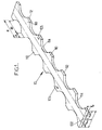
Figure 1 is a schematic perspective view of a first embodiment of a flexible reinforcing strip according to the invention; -
Figure 2 is a schematic perspective view of a second embodiment of a flexible reinforcing strip according to the invention; -
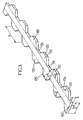
Figure 3 is a schematic perspective view of a third embodiment of a flexible reinforcing strip according to the invention; -
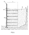
Figure 4 is a schematic view in cross section of a reinforced soil construction according to the invention while it is in the process of being built. - For clarity, the various components depicted in the figures are not necessarily drawn to scale. In these figures, identical references correspond to elements that are identical.
-
Figure 1 depicts a perspective view of a first embodiment of a flexible stabilizing strip (10) according to the invention. - The polymer matrix is, for example, based on polyethylene, polypropylene, PVC.
- The fibres are preferably polymer fibres, for example based on polyester, on polyamide or on polyolefin. Metal fibres or natural fibres, for example those based on hemp may supplement the polymer fibres. For preference, the polymer fibres are continuous fibres.
- The stabilizing
strip 10 is of a thickness e that is substantially constant across the entire width and along the longitudinal axis. It is made up of acentral portion 100 which runs longitudinally to withstand tensile forces and two symmetriclateral portions 105, situated one on each side of thecentral portion 100. Thelateral portions 105 each comprise a plurality ofsegments 110 arranged uniformly along the longitudinal axis. Eachsegment 110 comprises astraight part 112 and twocurved parts 114 which connect the ends of thestraight part 112 to a zero-width lateral portion region. - The
parts 114 depicted here are circular arcs. The width l1 of thecentral portion 100 is constant along the longitudinal axis and the width of each of thelateral portions 105 varies continuously between 0 and l2, l3 where l2, l3 correspond to the maximum width of the segments in the region corresponding to thestraight part 112. According to one embodiment, l2 is equal to l3. The maximum width of the flexible reinforcing strip is l where l = l1 + l2 + l3 and its minimum width is l1. - The
segments 110 are distributed along the longitudinal axis with a constant spacing P, where P = d1 d2 with d1 corresponding to the length of astraight part 112 and d2 corresponding to the distance between two consecutive ends of two consecutivestraight parts 112. -
Figure 2 depicts a perspective view of another embodiment of a flexible stabilizing strip according to the invention in which a different shape of segment has been chosen. Thesegments 110 ofFigure 1 are replaced here bysegments 120. Asegment 120 is a trapezium in which astraight part 122 runs parallel to the longitudinal axis and in which twostraight parts straight part 112 at an angle to a zero-width lateral portion region extending along thestraight part 124. - The
segments 120 are distributed along the longitudinal axis with a constant spacing P in which P = d3+d4+d5+d6 with d3 and d5 corresponding to the length of the projection onto the longitudinal axis of theangled parts straight part 124, and d6 corresponding to the length of thestraight part 122. - The stabilizing strips illustrated in
Figures 1 and2 can be obtained by cutting into the edges of a strip of width 1 in order to remove the material between thesegments - It is also possible to manufacture these strips using direct extrusion by varying the width of the extrusion head continuously from l1 to l during the extrusion process.
-
Figure 3 depicts an alternative form of embodiment of a flexible stabilizing strip ofFigure 2 in which thesegments 130, which have the same geometry as thesegments 120, are not arranged symmetrically along the longitudinal axis but are offset from one another in the lengthwise direction. In one embodiment, the maximum widths l2, l3 of the lateral portions are identical and the variable-width lateral portions 105 are arranged in such a way that the width of the stabilizing strip is constant over its entire length. - A strip such as this can be obtained by cutting the edges of a strip of width l + l2.
- However, it is advantageous to produce such a strip by direct extrusion by moving a constant-width extrusion head back and forth during the extrusion process in order to form the
segments 130. - The invention also relates to a method of building a reinforced soil construction.
-
Figure 4 illustrates such a method. A compactedbackfill 21, in which the stabilizing strips according to theinvention 10 are distributed, is delimited across the frontal side of the construction by a facing 23 built by juxtaposingprefabricated elements 24, and is delimited on the rear side by theland 25. - To give the construction some cohesion, the stabilizing
strips 10 may be connected to the facingelements 24 and may extend into thebackfill 21 over a certain distance. These stabilizingstrips 10 play a part in reinforcing the soil that lies in a reinforced region Z behind the facing 23. - In this reinforced region Z, the
backfill material 21 is very strong because it is reinforced by the stabilizing strips 10. It is thus able to sustain the shear stresses applied to it as a result of the tensile forces experienced by the stabilizing strips 10. This reinforced region Z naturally has to be thick enough to be able to hold the facing 23 sufficiently in place. - Simply connecting the stabilizing strips to the backs of the facing
elements 24 thus allows the facing to be kept pressed against the backfill of which there may be a vast volume. - In the example configuration of a construction which is illustrated in
Figure 4 , the stabilizingstrips 10 are positioned in superposed horizontal planes that alternate over the height of the construction. - In order to erect the construction shown in
Figure 4 one procedure may be as follows: - a) fitting some of the facing
elements 24 so as to be able thereafter to bring in some backfill material up to a certain height. In a known way, the building up and positioning of the facing elements may be made easier by assembly components positioned between them; - b) installing stabilizing
strips 10 in the backfill already present, applying light tension to them; - c) bringing in backfill material on top of the course of stabilizing
strips 10 that has just been installed, up to the next level of stabilizingstrips 10 on the rear side of the facingelements 24. This backfill material is compacted progressively as it is introduced; - d) repeating steps a) to c) until the uppermost level of backfill is reached.
- It should be noted that numerous alternative forms may be applied to the abovementioned structure and to the method of achieving it.
- It is also possible to use the flexible stabilizing strips according to the invention by securing them to a
wall 25 of the land by attaching them to the said wall, for example using hooks, rings nailed into thewall 25 or any other means known to those skilled in the art.
Claims (9)
- Flexible stabilizing strip (10) of substantially constant thickness e, intended to be used in reinforced soil constructions, comprising a central portion (100) running longitudinally in order to withstand tensile forces, and at least one variable-width lateral portion (105) comprising a plurality of segments (110, 120, 130) arranged in a continuity of material along the central portion (100).
- Flexible stabilizing strip (10) according to the preceding claim, characterized in that the central portion (100) essentially consists of a fibre-reinforced polymer matrix.
- Flexible stabilizing strip (10) according to the preceding claim, characterized in that the variable-width lateral portion (105) contains no fibres.
- Flexible stabilizing strip (10) according to any one of the preceding claims, characterized in that a variable-width lateral portion (105) lies on each side of the central portion (100).
- Flexible stabilizing strip (10) according to any one of the preceding claims, characterized in that each segment (110, 120, 130) of the variable-width lateral portion (105) has a maximum width (l2, l3) less than or equal to the width (l1) of the portion for withstanding tensile forces.
- Flexible stabilizing strip (10) according to any one of the preceding claims, characterized in that the variable-width lateral portion segments (120, 130) are in the shape of a parallelepiped, for example of a trapezium.
- Flexible stabilizing strip (10) according to any one of the preceding claims, characterized in that the variable-width lateral portion segments have a triangular shape.
- Flexible stabilizing strip (10) according to any one of Claims 1 to 4, characterized in that the variable-width lateral portion segments (110) have a shape comprising curved parts (114) that connect the tensile-force-withstanding central portion (100) to straight parts (112) that are parallel to the said central portion (100).
- Flexible stabilizing strip (10) according to any one of the preceding claims, characterized in that the variable-width lateral portion segments (110, 120, 130) extend over 20 to 80% of the length of the central portion (100).
Priority Applications (1)
| Application Number | Priority Date | Filing Date | Title |
|---|---|---|---|
| PL09716476T PL2247797T3 (en) | 2008-03-04 | 2009-02-16 | Flexible stabilizing strip intended to be used in reinforced soil constructions |
Applications Claiming Priority (2)
| Application Number | Priority Date | Filing Date | Title |
|---|---|---|---|
| FR0851407A FR2922234B1 (en) | 2008-03-04 | 2008-03-04 | FLEXIBLE STABILIZING STRIP INTENDED FOR USE IN REINFORCED STRUCTURED WORKS |
| PCT/EP2009/051812 WO2009109458A2 (en) | 2008-03-04 | 2009-02-16 | Flexible stabilizing strip intended to be used in reinforced soil constructions |
Publications (2)
| Publication Number | Publication Date |
|---|---|
| EP2247797A2 EP2247797A2 (en) | 2010-11-10 |
| EP2247797B1 true EP2247797B1 (en) | 2012-05-30 |
Family
ID=39731668
Family Applications (1)
| Application Number | Title | Priority Date | Filing Date |
|---|---|---|---|
| EP09716476A Active EP2247797B1 (en) | 2008-03-04 | 2009-02-16 | Flexible stabilizing strip intended to be used in reinforced soil constructions |
Country Status (19)
| Country | Link |
|---|---|
| US (1) | US20110044771A1 (en) |
| EP (1) | EP2247797B1 (en) |
| JP (1) | JP5053446B2 (en) |
| KR (1) | KR20100122847A (en) |
| CN (1) | CN102016182A (en) |
| AU (1) | AU2009221354A1 (en) |
| BR (1) | BRPI0908758B1 (en) |
| CA (1) | CA2717220C (en) |
| ES (1) | ES2388709T3 (en) |
| FR (1) | FR2922234B1 (en) |
| HK (1) | HK1150641A1 (en) |
| HR (1) | HRP20120671T1 (en) |
| MX (1) | MX2010009726A (en) |
| MY (1) | MY155553A (en) |
| PL (1) | PL2247797T3 (en) |
| PT (1) | PT2247797E (en) |
| RU (1) | RU2503778C2 (en) |
| WO (1) | WO2009109458A2 (en) |
| ZA (1) | ZA201006184B (en) |
Cited By (1)
| Publication number | Priority date | Publication date | Assignee | Title |
|---|---|---|---|---|
| US10501907B2 (en) | 2015-07-07 | 2019-12-10 | Terre Armee Internationale | Moulding insert and facing block with such an insert |
Families Citing this family (11)
| Publication number | Priority date | Publication date | Assignee | Title |
|---|---|---|---|---|
| EP2550406B1 (en) | 2010-03-25 | 2013-12-25 | Terre Armée Internationale | Retaining wall with reinforced earth elements in the backfill |
| EP2434059B1 (en) | 2010-09-24 | 2015-12-23 | Terre Armee Internationale | A reinforced soil structure |
| EP2434060B1 (en) * | 2010-09-24 | 2014-04-16 | Terre Armée Internationale | A reinforced soil structure |
| RU2482244C2 (en) * | 2011-08-15 | 2013-05-20 | Сергей Андреевич Путивский | Method for reinforcement of soil |
| CN102877468B (en) * | 2012-01-19 | 2015-04-08 | 湖南大学 | Non-adhesion prestressing reinforcement material |
| FR3016904B1 (en) * | 2014-01-27 | 2016-02-05 | Terre Armee Int | REINFORCED STABILIZATION STRIP FOR REINFORCED REINFORCING ARTICLES WITH FUNCTIONALIZED SHEATH |
| CN106337434B (en) * | 2016-08-30 | 2018-10-23 | 中国一冶集团有限公司 | A kind of reinforced earth retaining wall and its construction method |
| KR101988968B1 (en) * | 2017-05-29 | 2019-06-13 | (유)이안지오텍 | Reinforcement Grid for Retaining Wall and Constructing Method the Same |
| CN107447775A (en) * | 2017-08-09 | 2017-12-08 | 中国地质环境监测院 | Landslide disaster body makes ground draining reinforced earth retaining wall structure |
| KR20220002750U (en) * | 2020-09-03 | 2022-11-21 | 더 테일러 아이피 그룹 엘엘씨 | Improved Strip Soil Reinforcements and Manufacturing Methods |
| WO2023073394A1 (en) * | 2021-10-29 | 2023-05-04 | Soletanche Freyssinet | Reinforcement member for a stabilized soil structure, and stabilized soil structure including such reinforcement member |
Family Cites Families (8)
| Publication number | Priority date | Publication date | Assignee | Title |
|---|---|---|---|---|
| FR2325778A1 (en) * | 1975-09-26 | 1977-04-22 | Vidal Henri | REINFORCEMENT FOR WORK IN ARMED EARTH |
| GB2014221B (en) * | 1977-11-15 | 1982-04-15 | Transport Secretary Of State F | Stabilising elements for earth strucutres |
| JPS58120022U (en) * | 1982-02-10 | 1983-08-16 | 株式会社ブリヂストン | Variable mouthpiece for extruder for rubber-like materials |
| EP0724672B1 (en) * | 1993-10-22 | 2001-02-28 | Societe Civile Des Brevets Henri Vidal | Strip for use in stabilised earth structures |
| DE29814457U1 (en) * | 1997-10-03 | 1998-12-24 | Lupke Manfred Arno Alfred | Device for molding plastic parts |
| US6050746A (en) * | 1997-12-03 | 2000-04-18 | Michael W. Wilson | Underground reinforced soil/metal structures |
| RU2208091C1 (en) * | 2001-12-03 | 2003-07-10 | Дальневосточный государственный университет путей сообщения | Earth structure on soft foundation |
| US7270502B2 (en) * | 2005-01-19 | 2007-09-18 | Richard Brown | Stabilized earth structure reinforcing elements |
-
2008
- 2008-03-04 FR FR0851407A patent/FR2922234B1/en active Active
-
2009
- 2009-02-16 PT PT09716476T patent/PT2247797E/en unknown
- 2009-02-16 AU AU2009221354A patent/AU2009221354A1/en not_active Abandoned
- 2009-02-16 WO PCT/EP2009/051812 patent/WO2009109458A2/en active Application Filing
- 2009-02-16 MX MX2010009726A patent/MX2010009726A/en not_active Application Discontinuation
- 2009-02-16 US US12/921,019 patent/US20110044771A1/en not_active Abandoned
- 2009-02-16 ES ES09716476T patent/ES2388709T3/en active Active
- 2009-02-16 CN CN2009801157286A patent/CN102016182A/en active Pending
- 2009-02-16 CA CA2717220A patent/CA2717220C/en not_active Expired - Fee Related
- 2009-02-16 EP EP09716476A patent/EP2247797B1/en active Active
- 2009-02-16 BR BRPI0908758-3A patent/BRPI0908758B1/en not_active IP Right Cessation
- 2009-02-16 MY MYPI2010004166A patent/MY155553A/en unknown
- 2009-02-16 RU RU2010140433/03A patent/RU2503778C2/en not_active IP Right Cessation
- 2009-02-16 PL PL09716476T patent/PL2247797T3/en unknown
- 2009-02-16 JP JP2010549077A patent/JP5053446B2/en active Active
- 2009-02-16 KR KR1020097010447A patent/KR20100122847A/en not_active Application Discontinuation
-
2010
- 2010-08-30 ZA ZA2010/06184A patent/ZA201006184B/en unknown
-
2011
- 2011-05-09 HK HK11104598.5A patent/HK1150641A1/en not_active IP Right Cessation
-
2012
- 2012-08-20 HR HRP20120671AT patent/HRP20120671T1/en unknown
Cited By (1)
| Publication number | Priority date | Publication date | Assignee | Title |
|---|---|---|---|---|
| US10501907B2 (en) | 2015-07-07 | 2019-12-10 | Terre Armee Internationale | Moulding insert and facing block with such an insert |
Also Published As
| Publication number | Publication date |
|---|---|
| JP5053446B2 (en) | 2012-10-17 |
| MY155553A (en) | 2015-10-30 |
| RU2010140433A (en) | 2012-04-10 |
| FR2922234B1 (en) | 2017-12-22 |
| JP2011513611A (en) | 2011-04-28 |
| RU2503778C2 (en) | 2014-01-10 |
| KR20100122847A (en) | 2010-11-23 |
| BRPI0908758B1 (en) | 2019-06-18 |
| HK1150641A1 (en) | 2012-01-06 |
| WO2009109458A2 (en) | 2009-09-11 |
| MX2010009726A (en) | 2010-12-17 |
| EP2247797A2 (en) | 2010-11-10 |
| HRP20120671T1 (en) | 2012-10-31 |
| CN102016182A (en) | 2011-04-13 |
| US20110044771A1 (en) | 2011-02-24 |
| ES2388709T3 (en) | 2012-10-17 |
| PL2247797T3 (en) | 2012-12-31 |
| ZA201006184B (en) | 2011-11-30 |
| WO2009109458A3 (en) | 2009-11-05 |
| BRPI0908758A2 (en) | 2015-07-21 |
| PT2247797E (en) | 2012-08-21 |
| CA2717220C (en) | 2016-04-19 |
| CA2717220A1 (en) | 2009-09-11 |
| FR2922234A1 (en) | 2009-04-17 |
| AU2009221354A1 (en) | 2009-09-11 |
Similar Documents
| Publication | Publication Date | Title |
|---|---|---|
| EP2247797B1 (en) | Flexible stabilizing strip intended to be used in reinforced soil constructions | |
| US7850400B2 (en) | Stabilized soil structure and facing elements for its construction | |
| US7491018B2 (en) | Stabilized soil structure and facing elements for its construction | |
| KR20100071967A (en) | Reinforced stabilisation strip to be used in reinforced ground works | |
| US7789590B2 (en) | Stabilizing strip intended for use in reinforced earth structures | |
| US20100092249A1 (en) | Ground reinforced structure and reinforcement members for the construction thereof | |
| US8573894B2 (en) | Connection device for a reinforced earth structure and related structure and method | |
| CN108603351B (en) | Geosynthetic reinforced wallboard including earth reinforcement members | |
| EP1633937B1 (en) | Composite construction element, in particular for making wall structures for buildings and process for its manufacture | |
| MX2012010901A (en) | Building with reinforced ground. | |
| EP2372027B1 (en) | Facing element for use in a stabilized soil structure | |
| US20110058904A1 (en) | Stabilizing Reinforcement For Use In Reinforced Soil Works | |
| KR101465480B1 (en) | Prestressed Steel and Concrete Composite pile construction methods | |
| TW201038793A (en) | Flexible stabilizing strip intended to be used in reinforced soil constructions | |
| JPH0841889A (en) | Slope stabilizing structure |
Legal Events
| Date | Code | Title | Description |
|---|---|---|---|
| PUAI | Public reference made under article 153(3) epc to a published international application that has entered the european phase |
Free format text: ORIGINAL CODE: 0009012 |
|
| 17P | Request for examination filed |
Effective date: 20100826 |
|
| AK | Designated contracting states |
Kind code of ref document: A2 Designated state(s): AT BE BG CH CY CZ DE DK EE ES FI FR GB GR HR HU IE IS IT LI LT LU LV MC MK MT NL NO PL PT RO SE SI SK TR |
|
| AX | Request for extension of the european patent |
Extension state: AL BA RS |
|
| DAX | Request for extension of the european patent (deleted) | ||
| GRAP | Despatch of communication of intention to grant a patent |
Free format text: ORIGINAL CODE: EPIDOSNIGR1 |
|
| REG | Reference to a national code |
Ref country code: HK Ref legal event code: DE Ref document number: 1150641 Country of ref document: HK |
|
| GRAS | Grant fee paid |
Free format text: ORIGINAL CODE: EPIDOSNIGR3 |
|
| GRAA | (expected) grant |
Free format text: ORIGINAL CODE: 0009210 |
|
| AK | Designated contracting states |
Kind code of ref document: B1 Designated state(s): AT BE BG CH CY CZ DE DK EE ES FI FR GB GR HR HU IE IS IT LI LT LU LV MC MK MT NL NO PL PT RO SE SI SK TR |
|
| REG | Reference to a national code |
Ref country code: GB Ref legal event code: FG4D |
|
| REG | Reference to a national code |
Ref country code: CH Ref legal event code: EP |
|
| REG | Reference to a national code |
Ref country code: AT Ref legal event code: REF Ref document number: 560146 Country of ref document: AT Kind code of ref document: T Effective date: 20120615 |
|
| REG | Reference to a national code |
Ref country code: IE Ref legal event code: FG4D |
|
| REG | Reference to a national code |
Ref country code: DE Ref legal event code: R096 Ref document number: 602009007337 Country of ref document: DE Effective date: 20120726 |
|
| REG | Reference to a national code |
Ref country code: RO Ref legal event code: EPE Ref country code: HR Ref legal event code: TUEP Ref document number: P20120671 Country of ref document: HR |
|
| REG | Reference to a national code |
Ref country code: PT Ref legal event code: SC4A Free format text: AVAILABILITY OF NATIONAL TRANSLATION Effective date: 20120814 |
|
| REG | Reference to a national code |
Ref country code: NL Ref legal event code: T3 |
|
| REG | Reference to a national code |
Ref country code: SE Ref legal event code: TRGR |
|
| REG | Reference to a national code |
Ref country code: ES Ref legal event code: FG2A Ref document number: 2388709 Country of ref document: ES Kind code of ref document: T3 Effective date: 20121017 |
|
| REG | Reference to a national code |
Ref country code: LT Ref legal event code: MG4D Effective date: 20120530 |
|
| REG | Reference to a national code |
Ref country code: GR Ref legal event code: EP Ref document number: 20120401889 Country of ref document: GR Effective date: 20120920 |
|
| PG25 | Lapsed in a contracting state [announced via postgrant information from national office to epo] |
Ref country code: IS Free format text: LAPSE BECAUSE OF FAILURE TO SUBMIT A TRANSLATION OF THE DESCRIPTION OR TO PAY THE FEE WITHIN THE PRESCRIBED TIME-LIMIT Effective date: 20120930 Ref country code: CY Free format text: LAPSE BECAUSE OF FAILURE TO SUBMIT A TRANSLATION OF THE DESCRIPTION OR TO PAY THE FEE WITHIN THE PRESCRIBED TIME-LIMIT Effective date: 20120530 Ref country code: LT Free format text: LAPSE BECAUSE OF FAILURE TO SUBMIT A TRANSLATION OF THE DESCRIPTION OR TO PAY THE FEE WITHIN THE PRESCRIBED TIME-LIMIT Effective date: 20120530 Ref country code: NO Free format text: LAPSE BECAUSE OF FAILURE TO SUBMIT A TRANSLATION OF THE DESCRIPTION OR TO PAY THE FEE WITHIN THE PRESCRIBED TIME-LIMIT Effective date: 20120830 Ref country code: FI Free format text: LAPSE BECAUSE OF FAILURE TO SUBMIT A TRANSLATION OF THE DESCRIPTION OR TO PAY THE FEE WITHIN THE PRESCRIBED TIME-LIMIT Effective date: 20120530 |
|
| REG | Reference to a national code |
Ref country code: HR Ref legal event code: T1PR Ref document number: P20120671 Country of ref document: HR |
|
| PG25 | Lapsed in a contracting state [announced via postgrant information from national office to epo] |
Ref country code: LV Free format text: LAPSE BECAUSE OF FAILURE TO SUBMIT A TRANSLATION OF THE DESCRIPTION OR TO PAY THE FEE WITHIN THE PRESCRIBED TIME-LIMIT Effective date: 20120530 Ref country code: SI Free format text: LAPSE BECAUSE OF FAILURE TO SUBMIT A TRANSLATION OF THE DESCRIPTION OR TO PAY THE FEE WITHIN THE PRESCRIBED TIME-LIMIT Effective date: 20120530 |
|
| REG | Reference to a national code |
Ref country code: PL Ref legal event code: T3 |
|
| PG25 | Lapsed in a contracting state [announced via postgrant information from national office to epo] |
Ref country code: EE Free format text: LAPSE BECAUSE OF FAILURE TO SUBMIT A TRANSLATION OF THE DESCRIPTION OR TO PAY THE FEE WITHIN THE PRESCRIBED TIME-LIMIT Effective date: 20120530 Ref country code: DK Free format text: LAPSE BECAUSE OF FAILURE TO SUBMIT A TRANSLATION OF THE DESCRIPTION OR TO PAY THE FEE WITHIN THE PRESCRIBED TIME-LIMIT Effective date: 20120530 Ref country code: SK Free format text: LAPSE BECAUSE OF FAILURE TO SUBMIT A TRANSLATION OF THE DESCRIPTION OR TO PAY THE FEE WITHIN THE PRESCRIBED TIME-LIMIT Effective date: 20120530 Ref country code: CZ Free format text: LAPSE BECAUSE OF FAILURE TO SUBMIT A TRANSLATION OF THE DESCRIPTION OR TO PAY THE FEE WITHIN THE PRESCRIBED TIME-LIMIT Effective date: 20120530 |
|
| REG | Reference to a national code |
Ref country code: HK Ref legal event code: GR Ref document number: 1150641 Country of ref document: HK |
|
| PLBE | No opposition filed within time limit |
Free format text: ORIGINAL CODE: 0009261 |
|
| STAA | Information on the status of an ep patent application or granted ep patent |
Free format text: STATUS: NO OPPOSITION FILED WITHIN TIME LIMIT |
|
| 26N | No opposition filed |
Effective date: 20130301 |
|
| REG | Reference to a national code |
Ref country code: DE Ref legal event code: R097 Ref document number: 602009007337 Country of ref document: DE Effective date: 20130301 |
|
| PG25 | Lapsed in a contracting state [announced via postgrant information from national office to epo] |
Ref country code: BG Free format text: LAPSE BECAUSE OF FAILURE TO SUBMIT A TRANSLATION OF THE DESCRIPTION OR TO PAY THE FEE WITHIN THE PRESCRIBED TIME-LIMIT Effective date: 20120830 |
|
| PG25 | Lapsed in a contracting state [announced via postgrant information from national office to epo] |
Ref country code: MC Free format text: LAPSE BECAUSE OF NON-PAYMENT OF DUE FEES Effective date: 20130228 |
|
| PG25 | Lapsed in a contracting state [announced via postgrant information from national office to epo] |
Ref country code: MT Free format text: LAPSE BECAUSE OF FAILURE TO SUBMIT A TRANSLATION OF THE DESCRIPTION OR TO PAY THE FEE WITHIN THE PRESCRIBED TIME-LIMIT Effective date: 20120530 |
|
| REG | Reference to a national code |
Ref country code: FR Ref legal event code: CA Effective date: 20150112 |
|
| REG | Reference to a national code |
Ref country code: FR Ref legal event code: PLFP Year of fee payment: 7 |
|
| PG25 | Lapsed in a contracting state [announced via postgrant information from national office to epo] |
Ref country code: TR Free format text: LAPSE BECAUSE OF FAILURE TO SUBMIT A TRANSLATION OF THE DESCRIPTION OR TO PAY THE FEE WITHIN THE PRESCRIBED TIME-LIMIT Effective date: 20120530 |
|
| PG25 | Lapsed in a contracting state [announced via postgrant information from national office to epo] |
Ref country code: HU Free format text: LAPSE BECAUSE OF FAILURE TO SUBMIT A TRANSLATION OF THE DESCRIPTION OR TO PAY THE FEE WITHIN THE PRESCRIBED TIME-LIMIT; INVALID AB INITIO Effective date: 20090216 Ref country code: MK Free format text: LAPSE BECAUSE OF FAILURE TO SUBMIT A TRANSLATION OF THE DESCRIPTION OR TO PAY THE FEE WITHIN THE PRESCRIBED TIME-LIMIT Effective date: 20120530 Ref country code: LU Free format text: LAPSE BECAUSE OF NON-PAYMENT OF DUE FEES Effective date: 20130216 |
|
| REG | Reference to a national code |
Ref country code: FR Ref legal event code: PLFP Year of fee payment: 8 |
|
| REG | Reference to a national code |
Ref country code: HR Ref legal event code: ODRP Ref document number: P20120671 Country of ref document: HR Payment date: 20170123 Year of fee payment: 9 |
|
| REG | Reference to a national code |
Ref country code: FR Ref legal event code: PLFP Year of fee payment: 9 |
|
| PGFP | Annual fee paid to national office [announced via postgrant information from national office to epo] |
Ref country code: GR Payment date: 20170124 Year of fee payment: 9 Ref country code: CH Payment date: 20170125 Year of fee payment: 9 Ref country code: RO Payment date: 20170201 Year of fee payment: 9 Ref country code: SE Payment date: 20170124 Year of fee payment: 9 |
|
| PGFP | Annual fee paid to national office [announced via postgrant information from national office to epo] |
Ref country code: AT Payment date: 20170120 Year of fee payment: 9 Ref country code: IE Payment date: 20170123 Year of fee payment: 9 Ref country code: HR Payment date: 20170123 Year of fee payment: 9 Ref country code: PT Payment date: 20170201 Year of fee payment: 9 |
|
| REG | Reference to a national code |
Ref country code: FR Ref legal event code: PLFP Year of fee payment: 10 |
|
| REG | Reference to a national code |
Ref country code: HR Ref legal event code: PBON Ref document number: P20120671 Country of ref document: HR Effective date: 20180216 |
|
| REG | Reference to a national code |
Ref country code: CH Ref legal event code: PL |
|
| REG | Reference to a national code |
Ref country code: SE Ref legal event code: EUG |
|
| REG | Reference to a national code |
Ref country code: AT Ref legal event code: MM01 Ref document number: 560146 Country of ref document: AT Kind code of ref document: T Effective date: 20180216 |
|
| PG25 | Lapsed in a contracting state [announced via postgrant information from national office to epo] |
Ref country code: SE Free format text: LAPSE BECAUSE OF NON-PAYMENT OF DUE FEES Effective date: 20180217 Ref country code: PT Free format text: LAPSE BECAUSE OF NON-PAYMENT OF DUE FEES Effective date: 20180816 Ref country code: RO Free format text: LAPSE BECAUSE OF NON-PAYMENT OF DUE FEES Effective date: 20180216 |
|
| REG | Reference to a national code |
Ref country code: IE Ref legal event code: MM4A |
|
| PG25 | Lapsed in a contracting state [announced via postgrant information from national office to epo] |
Ref country code: GR Free format text: LAPSE BECAUSE OF NON-PAYMENT OF DUE FEES Effective date: 20180904 Ref country code: LI Free format text: LAPSE BECAUSE OF NON-PAYMENT OF DUE FEES Effective date: 20180228 Ref country code: AT Free format text: LAPSE BECAUSE OF NON-PAYMENT OF DUE FEES Effective date: 20180216 Ref country code: CH Free format text: LAPSE BECAUSE OF NON-PAYMENT OF DUE FEES Effective date: 20180228 Ref country code: HR Free format text: LAPSE BECAUSE OF NON-PAYMENT OF DUE FEES Effective date: 20180216 |
|
| PG25 | Lapsed in a contracting state [announced via postgrant information from national office to epo] |
Ref country code: IE Free format text: LAPSE BECAUSE OF NON-PAYMENT OF DUE FEES Effective date: 20180216 |
|
| PGFP | Annual fee paid to national office [announced via postgrant information from national office to epo] |
Ref country code: IT Payment date: 20190122 Year of fee payment: 11 |
|
| PGFP | Annual fee paid to national office [announced via postgrant information from national office to epo] |
Ref country code: DE Payment date: 20200121 Year of fee payment: 12 Ref country code: NL Payment date: 20200127 Year of fee payment: 12 Ref country code: PL Payment date: 20200123 Year of fee payment: 12 Ref country code: ES Payment date: 20200302 Year of fee payment: 12 |
|
| PGFP | Annual fee paid to national office [announced via postgrant information from national office to epo] |
Ref country code: BE Payment date: 20200124 Year of fee payment: 12 |
|
| REG | Reference to a national code |
Ref country code: DE Ref legal event code: R119 Ref document number: 602009007337 Country of ref document: DE |
|
| REG | Reference to a national code |
Ref country code: BE Ref legal event code: MM Effective date: 20210228 |
|
| PG25 | Lapsed in a contracting state [announced via postgrant information from national office to epo] |
Ref country code: IT Free format text: LAPSE BECAUSE OF NON-PAYMENT OF DUE FEES Effective date: 20200216 |
|
| REG | Reference to a national code |
Ref country code: NL Ref legal event code: MM Effective date: 20210301 |
|
| PG25 | Lapsed in a contracting state [announced via postgrant information from national office to epo] |
Ref country code: NL Free format text: LAPSE BECAUSE OF NON-PAYMENT OF DUE FEES Effective date: 20210301 |
|
| PG25 | Lapsed in a contracting state [announced via postgrant information from national office to epo] |
Ref country code: DE Free format text: LAPSE BECAUSE OF NON-PAYMENT OF DUE FEES Effective date: 20210901 |
|
| REG | Reference to a national code |
Ref country code: ES Ref legal event code: FD2A Effective date: 20220511 |
|
| PG25 | Lapsed in a contracting state [announced via postgrant information from national office to epo] |
Ref country code: ES Free format text: LAPSE BECAUSE OF NON-PAYMENT OF DUE FEES Effective date: 20210217 Ref country code: BE Free format text: LAPSE BECAUSE OF NON-PAYMENT OF DUE FEES Effective date: 20210228 |
|
| PG25 | Lapsed in a contracting state [announced via postgrant information from national office to epo] |
Ref country code: PL Free format text: LAPSE BECAUSE OF NON-PAYMENT OF DUE FEES Effective date: 20210216 |
|
| PGFP | Annual fee paid to national office [announced via postgrant information from national office to epo] |
Ref country code: FR Payment date: 20230119 Year of fee payment: 15 |
|
| PGFP | Annual fee paid to national office [announced via postgrant information from national office to epo] |
Ref country code: GB Payment date: 20230121 Year of fee payment: 15 |