EP2242279A2 - Projection apparatus and projection method - Google Patents
Projection apparatus and projection method Download PDFInfo
- Publication number
- EP2242279A2 EP2242279A2 EP10008057A EP10008057A EP2242279A2 EP 2242279 A2 EP2242279 A2 EP 2242279A2 EP 10008057 A EP10008057 A EP 10008057A EP 10008057 A EP10008057 A EP 10008057A EP 2242279 A2 EP2242279 A2 EP 2242279A2
- Authority
- EP
- European Patent Office
- Prior art keywords
- light emitting
- light
- projection
- emitting elements
- light source
- Prior art date
- Legal status (The legal status is an assumption and is not a legal conclusion. Google has not performed a legal analysis and makes no representation as to the accuracy of the status listed.)
- Granted
Links
- 238000000034 method Methods 0.000 title claims description 24
- 239000003086 colorant Substances 0.000 claims description 17
- 238000004040 coloring Methods 0.000 claims description 16
- 235000019557 luminance Nutrition 0.000 description 85
- 239000004065 semiconductor Substances 0.000 description 41
- 238000010586 diagram Methods 0.000 description 14
- 230000004907 flux Effects 0.000 description 10
- 230000004044 response Effects 0.000 description 8
- 238000006243 chemical reaction Methods 0.000 description 5
- 230000006870 function Effects 0.000 description 4
- 238000001514 detection method Methods 0.000 description 3
- 230000003287 optical effect Effects 0.000 description 3
- 108010043121 Green Fluorescent Proteins Proteins 0.000 description 2
- 238000009792 diffusion process Methods 0.000 description 2
- 239000003550 marker Substances 0.000 description 2
- 238000009877 rendering Methods 0.000 description 2
- 230000003111 delayed effect Effects 0.000 description 1
- 239000011521 glass Substances 0.000 description 1
- 239000004973 liquid crystal related substance Substances 0.000 description 1
- 230000002787 reinforcement Effects 0.000 description 1
- 230000001360 synchronised effect Effects 0.000 description 1
Images


Classifications
-
- H—ELECTRICITY
- H04—ELECTRIC COMMUNICATION TECHNIQUE
- H04N—PICTORIAL COMMUNICATION, e.g. TELEVISION
- H04N9/00—Details of colour television systems
- H04N9/12—Picture reproducers
- H04N9/31—Projection devices for colour picture display, e.g. using electronic spatial light modulators [ESLM]
- H04N9/3141—Constructional details thereof
- H04N9/315—Modulator illumination systems
- H04N9/3164—Modulator illumination systems using multiple light sources
-
- G—PHYSICS
- G03—PHOTOGRAPHY; CINEMATOGRAPHY; ANALOGOUS TECHNIQUES USING WAVES OTHER THAN OPTICAL WAVES; ELECTROGRAPHY; HOLOGRAPHY
- G03B—APPARATUS OR ARRANGEMENTS FOR TAKING PHOTOGRAPHS OR FOR PROJECTING OR VIEWING THEM; APPARATUS OR ARRANGEMENTS EMPLOYING ANALOGOUS TECHNIQUES USING WAVES OTHER THAN OPTICAL WAVES; ACCESSORIES THEREFOR
- G03B21/00—Projectors or projection-type viewers; Accessories therefor
- G03B21/14—Details
- G03B21/20—Lamp housings
- G03B21/2006—Lamp housings characterised by the light source
- G03B21/2033—LED or laser light sources
- G03B21/204—LED or laser light sources using secondary light emission, e.g. luminescence or fluorescence
-
- G—PHYSICS
- G03—PHOTOGRAPHY; CINEMATOGRAPHY; ANALOGOUS TECHNIQUES USING WAVES OTHER THAN OPTICAL WAVES; ELECTROGRAPHY; HOLOGRAPHY
- G03B—APPARATUS OR ARRANGEMENTS FOR TAKING PHOTOGRAPHS OR FOR PROJECTING OR VIEWING THEM; APPARATUS OR ARRANGEMENTS EMPLOYING ANALOGOUS TECHNIQUES USING WAVES OTHER THAN OPTICAL WAVES; ACCESSORIES THEREFOR
- G03B33/00—Colour photography, other than mere exposure or projection of a colour film
- G03B33/08—Sequential recording or projection
-
- H—ELECTRICITY
- H04—ELECTRIC COMMUNICATION TECHNIQUE
- H04N—PICTORIAL COMMUNICATION, e.g. TELEVISION
- H04N9/00—Details of colour television systems
- H04N9/12—Picture reproducers
- H04N9/31—Projection devices for colour picture display, e.g. using electronic spatial light modulators [ESLM]
- H04N9/3138—Projection devices for colour picture display, e.g. using electronic spatial light modulators [ESLM] using arrays of modulated light sources
-
- H—ELECTRICITY
- H04—ELECTRIC COMMUNICATION TECHNIQUE
- H04N—PICTORIAL COMMUNICATION, e.g. TELEVISION
- H04N9/00—Details of colour television systems
- H04N9/12—Picture reproducers
- H04N9/31—Projection devices for colour picture display, e.g. using electronic spatial light modulators [ESLM]
- H04N9/3141—Constructional details thereof
- H04N9/315—Modulator illumination systems
- H04N9/3155—Modulator illumination systems for controlling the light source
Definitions
- the present invention relates to a projection apparatus, for example, a data projection apparatus, and a projection method.
- LEDs light emitting diodes
- a projection apparatus including light emitting diodes (LEDs) as a light source, to enable the red, green, and blue light emitting diodes to be lit and dimmed and enable the temperatures of the R, G, and B light emitting diodes to be individually controlled to appropriately and smoothly adjust and maintain the brightness and light emission efficiency of a display screen in an image display section, while allowing power consumption to be easily reduced (see, for example, Jpn. Pat. Appln. KOKAI Publication No. 2005-181528 ).
- LEDs light emitting diodes
- a method of adjusting light emission duration and a method of adjusting light emission intensity are possible for techniques for dimming the light emitting diodes, serving as a light source, including the technique described in Jpn. Pat. Appln. KOKAI Publication No. 2005-181528 .
- the former method of adjusting the light emission duration of the light source needs to adjust time for which images are displayed by a light modulating element such as a liquid crystal display panel, Digital Micromirror Device (DMD) (registered trade mark), or the like which forms projection images, according to the adjusted light emission duration.
- a light modulating element such as a liquid crystal display panel, Digital Micromirror Device (DMD) (registered trade mark), or the like which forms projection images, according to the adjusted light emission duration.
- DMD Digital Micromirror Device
- gradation display requires very complicated control. Consequently, this method is not practicable.
- the latter method of adjusting the light emission intensity may involve, for example, controlling the current through each of the light emitting diodes.
- the driving current supplied to the light emitting diodes w1 to w5 is adjusted such that the luminance is 80%, 100%, and 60% of the rated value, respectively. All the light emitting diodes w1 to w5 are driven by a driving current of the same magnitude so as to emit light. Thus, the number of diodes simultaneously lit is always a total number, that is, "5".
- the driving current is adjusted in an analog manner, particularly when the current is reduced so as to provide a low luminance, a response time from the current state until the next desired emission luminance is obtained is disadvantageously increased.
- a method can be used which controls the number of light emitting diodes emitting light with a 100% luminance instead of adjusting the driving current for the individual light emitting diodes.
- FIG. 10 shows that a white light emitting diode group also using a color wheel is used as a light source.
- dimming is performed based on the number of light emitting diodes emitting light such that luminance is 80% of a rated value for projection of a red (R) image, is equal to the rated value, that is, 100% of the rated value, for projection of a green (G) image, and is 60% of the rated value for projection of a blue (B) image.
- FIG. 10(A) shows projection timings for each color image.
- FIG. 10(B) shows the light emission intensity of the white light emitting diode group.
- FIGS. 10(C) to 10(E) show how the white light emitting diode group is driven for each color image. Also in this case, the white light emitting diode group is assumed to be composed of a total of five light emitting diodes w1 to w5.
- the light emission duration varies among the plurality of light emitting elements making up the light source.
- the lifetime of the light emitting element located at the position where the element is most frequency used disadvantageously corresponds directly to the lifetime of the light source section as a whole.
- An object of the present invention is to provide a projection apparatus and a projection method which enable a plurality of light emitting elements to be efficiently driven to improve the quality of projection images and increase the lifetimes of all light emitting elements.
- a projection apparatus comprises a light source section having a plurality (n) of light emitting elements (where n is a natural number greater than one), and driving control means for driving each of the n light emitting elements comprising the light source section, by a pulse width modulation scheme with a phase difference based on ⁇ /n (where ⁇ is the lighting period unit), in synchronism with the lighting period unit of the light source section.
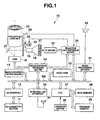
- FIG. 1 is a block diagram showing a general functional configuration of an electronic circuit provided in a data projection apparatus 10 according to the present embodiment.
- An I/O connector section 11 includes, for example, a pin jack (RCA) video input terminal, a D-sub15 type RGB input terminal, and a Universal Serial Bus (USB) connector.
- RCA pin jack
- USB Universal Serial Bus
- An image signal in conformity with various standards is input through the I/O connector section 11.
- the image signal is then input to an image conversion section 13 also called a scaler, via an I/O interface 12 and a system bus SB.
- the image conversion section 13 converts the image signal into a predetermined format suitable for projection.
- the image conversion section 13 then appropriately stores the resulting image signal in a video RAM 14 that is a buffer memory for display and then transmits the signal to a projection image processing section 15.
- the image conversion section 13 additionally processes the image signal as required by superimposing data such as symbols which indicate various operational states for on screen display (OSD), on the image signal.
- the image conversion section 13 transmits the processed image signal to the projection image processing section 15.
- the projection image processing section 15 multiplies a frame rate according to the predetermined format, for example, 30 frames per second, the division number of color components, and the number of display gray levels together to perform faster sequential driving.
- the projection image processing section 15 thus drives a micromirror element 16 that is a spatial optical modulation (SOM) element so that the element 16 displays the image.
- SOM spatial optical modulation
- the micromirror element 16 performs an individual, quick on/off operation on the inclination of each of a plurality of arrayed micromirrors corresponding to, for example, XGA (1,024 x 768 pixels) so that reflected light from the micromirrors form a light image.
- a LED array 17 is composed of a large number of regularly arrayed LEDs emitting white light with a high luminance. Light emitted by the LED array 17 is focused by a pyramidal housing 18 and changed to a luminous flux with an even luminance distribution by an integrator 19. The luminous flux is colored via a color wheel 20 and totally reflected by a mirror 21. The micromirror element 16 is irradiated with the luminous flux.
- Reflected light from the micromirror element forms a light image.
- the light image formed is projected and displayed, via a projection lens unit 22, on a screen (not shown in the drawings) serving as a projection target.
- plural groups for example, five groups of LEDs are controllably driven by a white (W) driver 23 so as to emit light.
- the white driver 23 drives the individual LED groups making up the LED array 17, using timings and driving currents based on control signals provided by a projection light processing section 24.
- the projection light processing section 24 controls light emission timings and driving currents for the white driver 23 in accordance with image data projection timing signals provided by the projection image processing section 24.
- the projection light processing section 24 not only supplies power to a motor (M) 25 rotating the color wheel 20 but also receives detection signals from a marker 26 located opposite a rotating circumferential end of the color wheel 20.
- CPU 27 performs control operations in the data projection apparatus 10 using a main memory 28 composed of DRAM and a program memory 29 made up of an electrically rewritable nonvolatile memory storing operation programs and various fixed data.
- the operation section 30 includes a key operation section provided on the main body of the data projection apparatus 10, and a laser light receiving section receiving infrared light from a remote controller (not shown in the drawings) dedicated for the data projection apparatus 10.
- the operation section 30 outputs key operation signals based on keys operated by a user directly or via the remote controller, directly to CPU 27.
- CPU 27 is further connected to an audio processing section 31 and a wireless LAN interface 32 via the system bus SB.
- the audio processing section 31 includes a sound source circuit such as a PCM sound source.
- the audio processing section 31 converts audio data provided during a projection operation into analog data, to drive a speaker section 33 for sound reinforcement and emission or generates a beep or the like as required.
- the wireless LAN interface 32 transmits and receives data, via a wireless LAN antenna 34, to and from a plurality of external apparatuses including a personal computer, using radio signals in the 2.4 GHz band in conformity with, for example, the IEEE 802.11g standards.
- the LED array 17 is divided into a plurality of, for example, five LED groups so that lighting timings for the respective LED groups are controlled.
- the LED array 17 is divided into the plurality of LED groups, it is desirable to, instead of orderly placing the arrayed LED groups in the five respective areas so that the groups do not overlap one another, arrange the LED groups so that the individual LEDs making up each of the LED groups are distributed as widely as possible, by mixing the five LED groups over as wide a range as possible so that adjacent LEDs belong to different groups. This allows light emitted by each of the LED groups to be formed into an even, proportionate luminous flux.
- FIG. 2 shows how the emission luminance of the LED array 17 while the color wheel 20 makes one rotation on the optical axis of the light source.
- the color wheel 20 has color filters for primary colors, for example, red (R), green (G), and blue (B) arranged like fans each of which has a center angle of 120° and which correspond to respective three divisions of the rotating circumference.
- the color filter 20 allows white light having exited the integrator 19 to pass through and is thus colored in one of red, green, and blue (to be exact, only light of the corresponding color component is transmitted).
- the micromirror element 16 then forms a color image of the corresponding color.
- FIG. 2(A) shows projection timings for each color image associated with the rotation of the color wheel 20.
- FIG. 2(B) shows the emission luminance of the LED array 17 obtained in synchronism with the projection timings.
- the unit of the projection period of a color image of each color component is defined as ⁇ as shown in FIG. 2 .
- the number of light emitting diodes emitting light is adjusted so that the luminance is 80% of a rated value for projection of a red image, is equal to the rated value, that is, 100% of the rated value, for projection of a green image, and is 60% of the rated value for projection of a blue image.
- FIGS. 2(C) to 2(E) show how the LED array 17 is driven for each color image.
- the LED array 17 is assumed to be composed of a total of five LED groups wg1 to wg5.
- phase difference pd ⁇ / n ⁇ i
- integer (i) is as large as possible within a scope permitted by the functions of the projection light processing section 24 and the W driver 23. This allows the five LED groups wg1 to wg5 to emit more averaged light.
- all of the five LED groups wg1 to wg5 are driven by pulse width modulation with a predetermined phase difference so as to emit light with an emission luminance accounting for 100% of the rated value.
- all of the five LED groups wg1 to wg5 are selected to emit light, all of the LED groups wg1 to wg5 are always lit during the period ⁇ .
- the LED groups are driven by pulse width modulation so as to emit light. Then, the lit LEDs are always driven by a current accounting for 100% of a corresponding rated value. Consequently, a sufficient response speed can be achieved.
- the LED groups are cyclically controllably turned on and off according to the above-described phase difference.
- the number of LED groups lit at each point in time is kept constant. This prevents light emission duration from being disproportionate among the LED groups. This allows operating time to be averaged.
- the LEDs can be efficiently driven to improve the quality of projection images and increase the lifetimes of all the light emitting elements.
- the LED array 17 is composed of a plurality of, for example, five LED groups.
- the present invention is not limited to this aspect.
- the LED array has a plurality of, for example, at least two light emitting elements, the LED array can be similarly controlled because the light emission luminance can be varied between two stages, that is, 100% and 50%.
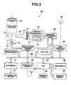
- FIG. 3 is a block diagram showing a general functional configuration of an electronic circuit provided in a data projection apparatus 50 according to the present embodiment.
- Many of the components of the data projection apparatus 50 according to the present embodiment except a light source system are basically configured similarly to the corresponding ones of the data projection apparatus 10 shown in FIG. 1 .
- the same components are denoted by the same reference numbers and will not be described.
- a LED array 51 is used as a light source for the present data projection apparatus 50.
- the LED array 51 is composed of a large number of regularly and mixedly arrayed LEDs emitting red, green, and blue light.
- Light of each color component emitted by the LED array 51 sequentially is focused by a pyramidal housing 18 with a reflection mirror stuck all over the inner surface of the housing 18.
- the light is then changed to a luminous flux with an even luminance distribution by an integrator 19.
- the luminous flux is totally reflected by a mirror 21.
- a micromirror element 16 is irradiated with the luminous flux.
- a red (R) driver 52 controllably drives the LED groups for the corresponding colors, which thus emit light in the primary colors, red, green, and blue.
- the red driver 52, the green driver 53, and the blue driver 54 drive the LED groups for the individual color components making up the LED array 51 using timings and driving currents based on control signals from a projection light processing section 55.
- the projection light processing section 55 controls the light emission timings and driving currents provided by the red driver 52, the green driver 53, and the blue driver 54 in accordance with image data provided by a projection image processing section 14.
- the LED array 51 is divided into a plurality of, for example, five LED groups for the respective color components so that lighting timings for the respective LED groups are controlled.
- the LED array 17 is divided into the plurality of LED groups for the respective colors, red, green, and blue
- FIG. 4 shows how the emission luminance of the LED array 51 is controlled while one frame of color images is being projected.
- FIG. 4(A) shows display timings for a red image, green image, and blue image formed by the micromirror element 16.
- FIG. 4(B) shows the emission luminance of the red LED group obtained in synchronism with the timings shown in FIG. 4(A) .
- FIG. 4(C) shows the emission luminance of the green LED group obtained in synchronism with the timings shown in FIG. 4(A).
- FIG. 4(D) shows the emission luminance of the blue LED group obtained in synchronism with the timings shown in FIG. 4(A) .
- the red LED group is driven so as to emit light with a 100% luminance
- the green LED group is driven so as to emit light with a 60% luminance
- the blue LED group is driven so as to emit light with a 20% luminance.
- the red LED group belonging to the LED array 51 as a product cannot emit light in red, which is an ideal wave band characteristic
- the green LED group and the blue LED group are simultaneously driven so as to emit light limitedly with the wave band characteristics of the green LED and blue LED groups taken into account. This improves color rendering properties.
- the green LED group is driven so as to emit light with a 100% luminance
- the red LED group is driven so as to emit light with a 40% luminance
- the blue LED group is driven so as to emit light with a 20% luminance.
- the blue LED group is driven so as to emit light with a 100% luminance
- the green LED group is driven so as to emit light with a 20% luminance.
- FIG. 5 shows a specific example of how the green LED group belonging to the LED array 51 is controllably driven so as to emit light as also described above with reference to FIG. 4(C) .
- the basic concept of the control is the same as that described with reference to FIG. 4(C) and also applied to the red LED and blue LED groups belonging to the LED array 51.
- the green LED group is cyclically controllably driven so as to emit light with a 60% luminance, a 100% luminance, and a 20% luminance as shown in FIG. 5(B) .
- the unit of the projection period of a color image of each color component is defined as ⁇ as shown in FIG. 5 .
- FIGS. 5(C) to 5(E) show how the green LED group is driven for each color image by the green driver 53.
- the green LED group is assumed to be composed of a total of five LED groups gg1 to gg5.
- phase difference pd ⁇ / n ⁇ i
- integer (i) is as large as possible within a scope permitted by the functions of the projection light processing section 55 and the green driver 53 (this also applies to the red driver 52 and the blue driver 54). This allows the five LED groups gg1 to gg5 to emit more averaged light.
- one of the five LED groups gg1 to gg5 is driven by pulse width modulation with a predetermined phase difference so as to always emit light with an emission luminance accounting for 100% of the rated value.
- the LED groups are driven by pulse width modulation so as to emit light. Then, the lit LEDs are always driven by a current accounting for 100% of a corresponding rated value. Consequently, a sufficient response speed can be achieved.
- the LED groups are cyclically controllably turned on and off according to the above-described phase difference.
- the number of LED groups lit at each point in time is kept constant. This prevents the light emission duration from being disproportionate among the LED groups. This allows the operating time to be averaged.
- the LED array 51 is divided into a plurality of, for example, five LED groups for the respective color components so that lighting timings for the respective LED groups are controlled.
- the LED array 51 is divided into the plurality of LED groups for the respective colors, red, green, and blue
- FIG. 6 shows the emission luminance particularly of the green LED group in the LED array 51.
- the ratio of the emission luminances of the green LED, red LED, and blue LED groups itself is similar to that shown in FIG. 4 described above. That is, the green LED group is driven by the projection light processing section 55 and the green driver 53 so as to emit light with a 60% luminance, a 100% luminance, and a 20% luminance in synchronism with the display timings for a red image, a green image, and a blue image formed by the micromirror element 16.
- one frame of color image as a whole is divided into nine periods of the respective fields.
- Each of the projection periods of red, green, and blue is cyclically arranged three times so that the same red, green, or blue image is repeatedly projected three times.
- the green LED group is cyclically controllably driven so as to emit light with a 60% luminance, a 100% luminance, and a 20% luminance as shown in FIG. 6(B) .
- the unit of the projection period of a color image of each color component is defined as ⁇ /3.
- FIGS. 6(C) to 6(E) show how the green LED group is driven by the green driver 53 during each of three projections of an red image while one frame of color image is being projected.
- the green LED group is assumed to be composed of a total of five LED groups gg1 to gg5.
- three of the five LED groups gg1 to gg5, particularly the first, second, and fifth LED groups gg1, gg2, and gg5, are driven by pulse width modulation with a predetermined phase difference for the period ⁇ /3 so as to always emit light with an emission luminance accounting for 100% of the rated value.
- the original red image projection period is divided into three portions, and those of the five LED groups gg1 to gg5 are sequentially switched to average the light emission durations of the LED groups gg1 to gg5.
- light emission driving is performed with appropriate LED groups sequentially selected according to the required emission luminance.
- the lit LEDs are driven with a current accounting for 100% of the corresponding rated value.
- the LED groups are driven so as to emit light such that the light emission position is switched in synchronism with each of m, (in the present embodiment, three) equal division periods into which the light emission duration unit for each of the red driver 52, the green driver 53, and the blue driver 54 is divided (m is a natural number greater than one). This prevents the light emission duration from being disproportionate among the LED groups. Consequently, the operating time can be averaged.
- the light source for the plurality of colors forming color images is controlled in connection with the luminance required for each color component so as to allow the plurality of colors to be simultaneously subjected to light emission driving; for example, during the original red image projection period, the green and blue colors are subjected to light emission driving simultaneously with the R color.
- the color rendering properties can be improved.
- FIG. 7 is a block diagram showing a general functional configuration of an electronic circuit provided in a data projection apparatus 70 according to the present embodiment.
- Many of the components of the data projection apparatus 70 according to the present embodiment except a light source system are basically configured similarly to the corresponding ones of the data projection apparatus 10 shown in FIG. 1 . Thus, the same components are denoted by the same reference numbers and will not be described.
- a semiconductor laser array 71 is used as a light source for the present data projection apparatus 70.
- the semiconductor laser array 71 is composed of a plurality of, for example, five arrayed semiconductor lasers oscillating at the frequency of blue (B) light.
- FIG. 7 is a simplified diagram showing the configuration of the semiconductor laser array 71 as viewed from the side of the array 71. By arranging four semiconductor lasers at an equal distance, on the left, right, top, and bottom, respectively, from one different semiconductor laser as viewed from the front of the array 71, the array can be composed of a total of five closely-arranged semiconductor lasers.
- a plurality of single-color laser beams oscillating the semiconductor laser array 71 are appropriately colored by a rotating fluorescent color wheel 72.
- the laser beams are then changed to a luminous flux with an even luminance distribution by an integrator 73.
- the laser beams are subsequently focused by a light source-side lens system 74 and then totally reflected by a mirror 21.
- the micromirror element 16 is then irradiated with the laser beams.
- the fluorescent color wheel 72 is composed of a total of three fan-shaped color filters dividing the circumference on a disc and including a transparent filter made up of, for example, colorless diffusion glass, an red fluorescent filter coated with a red fluophor, and a green fluorescent filter coated with a green fluophor.
- a motor 25 drivingly rotates the fluorescent color wheel 72 so that a plurality of points on the circumference of the fluorescent color wheel 72 are irradiated with the respective blue laser beams from the semiconductor laser array 71.
- the transparent filter allows the blue laser beams to pass through while diffusing the laser beams.
- the red fluorescent filter is irradiated with the blue laser beams to excite and emit red fluorescence from a surface located opposite an incident surface while diffusing the fluorescence.
- the green fluorescent filter is irradiated with the blue laser beams to excite and emit green fluorescence from a surface located opposite an incident surface while diffusing the fluorescence.
- the fluorescent color wheel 72 rotates to allow light in the primary colors, red, green, and blue to be emitted sequentially.
- the micromirror element 16 is then irradiated with the light via the integrator 73, the light source side lens system 74, and the mirror 21.
- the semiconductor laser array 71 is individually drivingly oscillated by a laser driver 75.
- the laser driver 75 drives the individual semiconductor lasers making up the semiconductor laser array 71, using timings and driving currents based on control signals from a projection light processing section 76.
- the projection light processing section 76 controls the light emission timings and driving currents provided by the laser driver 75 in accordance with image data provided by a projection image processing section 14. Furthermore, the projection light processing section 76 not only supplies power to a motor (M) 77 rotating the fluorescent color wheel 72 but also receives detection signals from a marker 78 located opposite a rotating circumferential end of the fluorescent color wheel 72 for synchronous detection.
- M motor
- FIG. 8 shows how the emission luminance of the semiconductor laser array 71 as a whole while the fluorescent color wheel 72 making one rotation on the optical axis of the light source.
- the red (R) fluorescent filter, the green (G) fluorescent filter, and blue (B) transparent diffusion filter are arranged like fans each of which has a center angle of 120 degrees and which correspond to respective three divisions of the rotating circumference.
- red light and green light, resulting from the excited corresponding phosphors, and blue light, that is, transmitted light are emitted sequentially while being dispersed.
- the micromirror element 16 thus forms a color image of the corresponding color.
- FIG. 8(A) shows projection timings for each color image associated with the rotation of the fluorescent color wheel 72.
- FIG. 8(B) shows the emission luminance of the semiconductor laser array 71 obtained in synchronism with the projection timings.
- the unit of the projection period of a color image of each color component is defined as ⁇ as shown in FIG. 8 .
- dimming is performed on the basis of the number of semiconductor lasers emitting light so that the luminance is 80% of a rated value for projection of an red image, is equal to the rated value, that is, 100% of the rated value, for projection of a green image, and is 60% of the rated value for projection of a blue image.
- FIGS. 8(C) to 8(E) show how the semiconductor laser array 71 is driven for each color image.
- the semiconductor laser array 71 is assumed to be composed of a total of five semiconductor lasers LD1 to LD5.
- FIG. 8(C) to allow the semiconductor laser array 71 to provide an 80% luminance, four of the five semiconductor lasers LD1 to LD5 are driven by pulse width modulation with a predetermined phase difference so as to always emit light with an emission luminance accounting for 100% of the rated value.
- phase difference pd ⁇ / n ⁇ i
- integer (i) is as large as possible within a scope permitted by the functions of the projection light processing section 76 and the laser driver 75. This allows the five semiconductor lasers LD1 to LD5 to emit more averaged light.
- all of the five semiconductor lasers LD1 to LD5 are driven by pulse width modulation with a predetermined phase difference so as to emit light with an emission luminance accounting for 100% of the rated value.
- all of the five semiconductor lasers LD1 to LD5 are selected to emit light, all of the semiconductor lasers LD1 to LD5 are always lit during the period X.
- FIG. 8(E) to allow the semiconductor laser array 71 to provide a 60% luminance, three of the five semiconductor lasers LD1 to LD5 are driven by pulse width modulation with a predetermined phase difference so as to always emit light with an emission luminance accounting for 100% of the rated value.
- the semiconductor lasers are driven by pulse width modulation so as to emit light. Then, the lit semiconductor lasers are always driven by a current accounting for 100% of a corresponding rated value. Consequently, a sufficient response speed can be achieved.
- the semiconductor lasers LD1 to LD5 are cyclically controllably turned on and off according to the above-described phase difference.
- the number of semiconductor lasers lit at each point in time is kept constant. This prevents the light emission duration from being disproportionate among the semiconductor laser. This allows the operating time to be averaged.
- the semiconductor lasers can be efficiently driven to improve the quality of projection images and increase the lifetimes of all the light emitting elements.
- the present invention is applied to the semiconductor lasers.
- the present invention is not limited to this aspect but is similarly applicable to a second harmonic generation (SHG) laser, a gas laser, or the like.
- the present invention is applied to the data projection apparatus.
- the present invention is not limited to this aspect but is similarly applicable to a projection apparatus using a plurality of light emitting elements such as LEDs or semiconductor lasers or a rear projection television receiver using such a projection apparatus.
- the present invention is not limited to the above-described embodiments. In practice, many variations may be made to the embodiments without departing from the scope of the present invention. Furthermore, the functions executed in the above-described embodiments may be appropriately combined together if possible. Each of the above-described embodiments includes various stages. Various inventions can thus be extracted by appropriately combining a plurality of the disclosed components. For example, if the embodiment from which some of the components shown in the embodiment are deleted is still effective, the configuration from which the components have been deleted can be extracted as an invention.
Abstract
Description
- The present invention relates to a projection apparatus, for example, a data projection apparatus, and a projection method.
- Techniques have been proposed which are used for a projection apparatus including light emitting diodes (LEDs) as a light source, to enable the red, green, and blue light emitting diodes to be lit and dimmed and enable the temperatures of the R, G, and B light emitting diodes to be individually controlled to appropriately and smoothly adjust and maintain the brightness and light emission efficiency of a display screen in an image display section, while allowing power consumption to be easily reduced (see, for example, Jpn. Pat. Appln. KOKAI Publication No.
2005-181528 - A method of adjusting light emission duration and a method of adjusting light emission intensity are possible for techniques for dimming the light emitting diodes, serving as a light source, including the technique described in Jpn. Pat. Appln. KOKAI Publication No.
2005-181528 - The former method of adjusting the light emission duration of the light source needs to adjust time for which images are displayed by a light modulating element such as a liquid crystal display panel, Digital Micromirror Device (DMD) (registered trade mark), or the like which forms projection images, according to the adjusted light emission duration. In particular, gradation display requires very complicated control. Consequently, this method is not practicable.
- Furthermore, the latter method of adjusting the light emission intensity may involve, for example, controlling the current through each of the light emitting diodes.
-
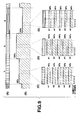
FIG. 9 shows that a white light emitting diode group also using a color wheel is used as a light source. In this case, dimming is performed such that luminance is 80% of a rated value for projection of a red (R) image, is equal to the rated value, that is, 100% of the rated value, for projection of a green (G) image, and is 60% of the rated value for projection of a blue (B) image. -
FIG. 9(A) shows projection timings for each color image.FIG. 9(B) shows the light emission intensity of the white light emitting diode group.FIGS. 9(C) to 9(E) show how the white light emitting diode group is driven for each color image. Here, for simplification of description, the white light emitting diode group is assumed to be composed of a total of five light emitting diodes w1 to w5. - As shown in
FIGS. 9(C) to 9(E) , when a red (R) image, a green (G) image, and a blue (B) image are projected, the driving current supplied to the light emitting diodes w1 to w5 is adjusted such that the luminance is 80%, 100%, and 60% of the rated value, respectively. All the light emitting diodes w1 to w5 are driven by a driving current of the same magnitude so as to emit light. Thus, the number of diodes simultaneously lit is always a total number, that is, "5". - As described above, if the driving current is adjusted in an analog manner, particularly when the current is reduced so as to provide a low luminance, a response time from the current state until the next desired emission luminance is obtained is disadvantageously increased.
- For example, in
FIG. 9(B) , described above, no problem occurs when the emission luminance changes from 80% to 100%. However, both when the emission luminance changes from 60% to 80% and when the emission luminance changes from 100% to 60%, the response is delayed, thus hindering accurate gradation display. - In order to avoid a possible decrease in response speed based on the adjustment of the driving current, a method can be used which controls the number of light emitting diodes emitting light with a 100% luminance instead of adjusting the driving current for the individual light emitting diodes.
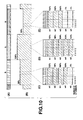
-
FIG. 10 shows that a white light emitting diode group also using a color wheel is used as a light source. In this case, dimming is performed based on the number of light emitting diodes emitting light such that luminance is 80% of a rated value for projection of a red (R) image, is equal to the rated value, that is, 100% of the rated value, for projection of a green (G) image, and is 60% of the rated value for projection of a blue (B) image. -
FIG. 10(A) shows projection timings for each color image.FIG. 10(B) shows the light emission intensity of the white light emitting diode group.FIGS. 10(C) to 10(E) show how the white light emitting diode group is driven for each color image. Also in this case, the white light emitting diode group is assumed to be composed of a total of five light emitting diodes w1 to w5. - As shown in
FIGS. 10(C) to 10(E) , when a red (R) image, a green (G) image, and a blue (B) image are projected, the number of those of the light emitting diodes w1 to w5 which emit light is adjusted such that the luminance is 80%, 100%, and 60% of the rated value, respectively. - In
FIG. 10(C) , to allow the white light emitting diode group as a whole to provide an 80% luminance, four of the five light emitting diodes w1 to w5, that is, the light emitting diodes w1 to w4, are driven so as to emit light with a luminance accounting for 100% of the rated value, with the remaining one light emitting diode w5 totally prevented from being driven. - In
FIG. 10(D) , to allow the white light emitting diode group as a whole to provide a 100% luminance, all the five light emitting diodes w1 to w5 are driven so as to emit light with a luminance accounting for 100% of the rated value. - In
FIG. 10(E) , to allow the white light emitting diode group as a whole to provide a 60% luminance, three of the five light emitting diodes w1 to w5, that is, the light emitting diodes w1 to w3, are driven so as to emit light with a luminance accounting for 100% of the rated value, with the remaining two light emitting diodes w4 and w5 totally prevented from being driven. - If the number of light emitting elements emitting light is adjusted to obtain the currently required luminance as described above, all the elements to emit light are driven at the rated value. This prevents a sufficient response speed from being achieved.
- In contrast, the light emission duration varies among the plurality of light emitting elements making up the light source. As a result, the lifetime of the light emitting element located at the position where the element is most frequency used disadvantageously corresponds directly to the lifetime of the light source section as a whole.
- The present invention has been made in view of the above-described circumstances. An object of the present invention is to provide a projection apparatus and a projection method which enable a plurality of light emitting elements to be efficiently driven to improve the quality of projection images and increase the lifetimes of all light emitting elements.
- A projection apparatus according to an aspect of the present invention comprises a light source section having a plurality (n) of light emitting elements (where n is a natural number greater than one), and driving control means for driving each of the n light emitting elements comprising the light source section, by a pulse width modulation scheme with a phase difference based on λ/n (where λ is the lighting period unit), in synchronism with the lighting period unit of the light source section.
- The invention can be more fully understood from the following detailed description when taken in conjunction with the accompanying drawings, in which:
-
FIG. 1 is a block diagram showing a general functional configuration of an electronic circuit in a data projection apparatus according to a first embodiment of the present invention; -
FIG. 2 is a diagram showing an example of how dimming is performed by a sequentially driven light source according to the first embodiment; -
FIG. 3 is a block diagram showing a general functional configuration of an electronic circuit in a data projection apparatus according to a second embodiment of the present invention; -
FIG. 4 is a diagram showing an example of how dimming is performed by a sequentially driven light source according to the second embodiment; -
FIG. 5 is a diagram showing the example of how dimming is performed by the sequentially driven light source according to the second embodiment; -
FIG. 6 is a diagram showing another example of how dimming is performed by the sequentially driven light source according to the second embodiment; -
FIG. 7 is a block diagram showing a general functional configuration of an electronic circuit in a data projection apparatus according to a third embodiment of the present invention; -
FIG. 8 is a diagram showing an example of how dimming is performed by a sequentially driven light source according to the third embodiment; -
FIG. 9 is a diagram showing an example of how dimming is performed by a common sequentially driven light source; and -
FIG. 10 is a diagram showing an example of how dimming is performed by a common sequentially driven light source. - Preferred embodiments for carrying out the present invention will be described below with reference to the drawings. Various limitations that are technically preferable for carrying out the present invention are imposed on the embodiments described below. In spite of the limitations, the scope of the present invention is not limited to the following embodiments and illustrated examples.
- A first embodiment in which the present invention is applied to a data projection apparatus will be described with reference to the drawings.
-
FIG. 1 is a block diagram showing a general functional configuration of an electronic circuit provided in adata projection apparatus 10 according to the present embodiment. - An I/
O connector section 11 includes, for example, a pin jack (RCA) video input terminal, a D-sub15 type RGB input terminal, and a Universal Serial Bus (USB) connector. - An image signal in conformity with various standards is input through the I/
O connector section 11. The image signal is then input to animage conversion section 13 also called a scaler, via an I/O interface 12 and a system bus SB. Theimage conversion section 13 converts the image signal into a predetermined format suitable for projection. Theimage conversion section 13 then appropriately stores the resulting image signal in avideo RAM 14 that is a buffer memory for display and then transmits the signal to a projectionimage processing section 15. - At this time, the
image conversion section 13 additionally processes the image signal as required by superimposing data such as symbols which indicate various operational states for on screen display (OSD), on the image signal. Theimage conversion section 13 transmits the processed image signal to the projectionimage processing section 15. - In accordance with the transmitted image signal, the projection
image processing section 15 multiplies a frame rate according to the predetermined format, for example, 30 frames per second, the division number of color components, and the number of display gray levels together to perform faster sequential driving. The projectionimage processing section 15 thus drives amicromirror element 16 that is a spatial optical modulation (SOM) element so that theelement 16 displays the image. - The
micromirror element 16 performs an individual, quick on/off operation on the inclination of each of a plurality of arrayed micromirrors corresponding to, for example, XGA (1,024 x 768 pixels) so that reflected light from the micromirrors form a light image. - On the other hand, a
LED array 17 is composed of a large number of regularly arrayed LEDs emitting white light with a high luminance. Light emitted by theLED array 17 is focused by apyramidal housing 18 and changed to a luminous flux with an even luminance distribution by anintegrator 19. The luminous flux is colored via acolor wheel 20 and totally reflected by amirror 21. Themicromirror element 16 is irradiated with the luminous flux. - Reflected light from the micromirror element forms a light image. The light image formed is projected and displayed, via a
projection lens unit 22, on a screen (not shown in the drawings) serving as a projection target. - In the
LED array 17, plural groups, for example, five groups of LEDs are controllably driven by a white (W)driver 23 so as to emit light. - The
white driver 23 drives the individual LED groups making up theLED array 17, using timings and driving currents based on control signals provided by a projectionlight processing section 24. - The projection
light processing section 24 controls light emission timings and driving currents for thewhite driver 23 in accordance with image data projection timing signals provided by the projectionimage processing section 24. - Moreover, the projection
light processing section 24 not only supplies power to a motor (M) 25 rotating thecolor wheel 20 but also receives detection signals from amarker 26 located opposite a rotating circumferential end of thecolor wheel 20. - All of the operation of each circuit described above is controlled by
CPU 27.CPU 27 performs control operations in thedata projection apparatus 10 using amain memory 28 composed of DRAM and aprogram memory 29 made up of an electrically rewritable nonvolatile memory storing operation programs and various fixed data. -
CPU 27 performs various projection operations in response to key operation signals from anoperation section 30. Theoperation section 30 includes a key operation section provided on the main body of thedata projection apparatus 10, and a laser light receiving section receiving infrared light from a remote controller (not shown in the drawings) dedicated for thedata projection apparatus 10. Theoperation section 30 outputs key operation signals based on keys operated by a user directly or via the remote controller, directly toCPU 27. -
CPU 27 is further connected to anaudio processing section 31 and awireless LAN interface 32 via the system bus SB. - The
audio processing section 31 includes a sound source circuit such as a PCM sound source. Theaudio processing section 31 converts audio data provided during a projection operation into analog data, to drive aspeaker section 33 for sound reinforcement and emission or generates a beep or the like as required. - The
wireless LAN interface 32 transmits and receives data, via awireless LAN antenna 34, to and from a plurality of external apparatuses including a personal computer, using radio signals in the 2.4 GHz band in conformity with, for example, the IEEE 802.11g standards. - Now, the operation of the above-described embodiment will be described.
- In the present embodiment, as described above, the
LED array 17 is divided into a plurality of, for example, five LED groups so that lighting timings for the respective LED groups are controlled. In this case, when theLED array 17 is divided into the plurality of LED groups, it is desirable to, instead of orderly placing the arrayed LED groups in the five respective areas so that the groups do not overlap one another, arrange the LED groups so that the individual LEDs making up each of the LED groups are distributed as widely as possible, by mixing the five LED groups over as wide a range as possible so that adjacent LEDs belong to different groups. This allows light emitted by each of the LED groups to be formed into an even, proportionate luminous flux. -
FIG. 2 shows how the emission luminance of theLED array 17 while thecolor wheel 20 makes one rotation on the optical axis of the light source. Thecolor wheel 20 has color filters for primary colors, for example, red (R), green (G), and blue (B) arranged like fans each of which has a center angle of 120° and which correspond to respective three divisions of the rotating circumference. Thecolor filter 20 allows white light having exited theintegrator 19 to pass through and is thus colored in one of red, green, and blue (to be exact, only light of the corresponding color component is transmitted). Themicromirror element 16 then forms a color image of the corresponding color. -
FIG. 2(A) shows projection timings for each color image associated with the rotation of thecolor wheel 20.FIG. 2(B) shows the emission luminance of theLED array 17 obtained in synchronism with the projection timings. The unit of the projection period of a color image of each color component is defined as λ as shown inFIG. 2 . - In the present embodiment, a case is illustrated where the number of light emitting diodes emitting light is adjusted so that the luminance is 80% of a rated value for projection of a red image, is equal to the rated value, that is, 100% of the rated value, for projection of a green image, and is 60% of the rated value for projection of a blue image.
-
FIGS. 2(C) to 2(E) show how theLED array 17 is driven for each color image. Here, as described above, theLED array 17 is assumed to be composed of a total of five LED groups wg1 to wg5. - In
FIG. 2(C) , to allow theLED array 17 as a whole to provide an 80% luminance, four of the five LED groups wg1 to wg5 are driven by pulse width modulation with a predetermined phase difference so as to always emit light with an emission luminance accounting for 100% of the rated value. - Here, when the number of LED groups and any positive integral number are defined as n and i, respectively, the above-described phase difference pd can be expressed by:

- The above-described integer (i) is as large as possible within a scope permitted by the functions of the projection
light processing section 24 and theW driver 23. This allows the five LED groups wg1 to wg5 to emit more averaged light. - In
FIG. 2(D) , to allow theLED array 17 as a whole to provide a 100% luminance, all of the five LED groups wg1 to wg5 are driven by pulse width modulation with a predetermined phase difference so as to emit light with an emission luminance accounting for 100% of the rated value. However, since all of the five LED groups wg1 to wg5 are selected to emit light, all of the LED groups wg1 to wg5 are always lit during the period λ. - In
FIG. 2(E) , to allow the LED array to provide a 60% luminance, three of the five LED groups wg1 to wg5 are driven by pulse width modulation with a predetermined phase difference so as to always emit light with an emission luminance accounting for 100% of the rated value. - As described above, with the phase difference set in association with the number of the LED groups, the LED groups are driven by pulse width modulation so as to emit light. Then, the lit LEDs are always driven by a current accounting for 100% of a corresponding rated value. Consequently, a sufficient response speed can be achieved.
- In addition, the LED groups are cyclically controllably turned on and off according to the above-described phase difference. The number of LED groups lit at each point in time is kept constant. This prevents light emission duration from being disproportionate among the LED groups. This allows operating time to be averaged.
- As described above, according to the present embodiment, if a plurality of high-luminance white LEDs are used as light emitting elements for a light source, the LEDs can be efficiently driven to improve the quality of projection images and increase the lifetimes of all the light emitting elements.
- In the above-described embodiment, the
LED array 17 is composed of a plurality of, for example, five LED groups. However, the present invention is not limited to this aspect. Provided that the LED array has a plurality of, for example, at least two light emitting elements, the LED array can be similarly controlled because the light emission luminance can be varied between two stages, that is, 100% and 50%. - A second embodiment in which the present invention is applied to a data projection apparatus will be described with reference to the drawings.
-
FIG. 3 is a block diagram showing a general functional configuration of an electronic circuit provided in adata projection apparatus 50 according to the present embodiment. Many of the components of thedata projection apparatus 50 according to the present embodiment except a light source system are basically configured similarly to the corresponding ones of thedata projection apparatus 10 shown inFIG. 1 . Thus, the same components are denoted by the same reference numbers and will not be described. - A
LED array 51 is used as a light source for the presentdata projection apparatus 50. TheLED array 51 is composed of a large number of regularly and mixedly arrayed LEDs emitting red, green, and blue light. Light of each color component emitted by theLED array 51 sequentially is focused by apyramidal housing 18 with a reflection mirror stuck all over the inner surface of thehousing 18. The light is then changed to a luminous flux with an even luminance distribution by anintegrator 19. The luminous flux is totally reflected by amirror 21. Amicromirror element 16 is irradiated with the luminous flux. - In the
LED array 51, a red (R)driver 52, a green (G)driver 53, and a blue (B)driver 54 controllably drives the LED groups for the corresponding colors, which thus emit light in the primary colors, red, green, and blue. - The
red driver 52, thegreen driver 53, and theblue driver 54 drive the LED groups for the individual color components making up theLED array 51 using timings and driving currents based on control signals from a projectionlight processing section 55. - The projection
light processing section 55 controls the light emission timings and driving currents provided by thered driver 52, thegreen driver 53, and theblue driver 54 in accordance with image data provided by a projectionimage processing section 14. - The operation of the above-described embodiment will be described. In the present embodiment, as described above, the
LED array 51 is divided into a plurality of, for example, five LED groups for the respective color components so that lighting timings for the respective LED groups are controlled. In this case, when theLED array 17 is divided into the plurality of LED groups for the respective colors, red, green, and blue, it is desirable to, instead of orderly placing the arrayed LED groups in the five respective areas so that the groups do not overlap one another, arrange the LED groups so that the individual LEDs making up each of the LED groups are distributed as widely as possible, by mixing the five LED groups over as wide a range as possible so that even adjacent LEDs in the same color belong to different groups. This allows light emitted by each of the LED groups to be formed into an even, proportionate luminous flux. -
FIG. 4 shows how the emission luminance of theLED array 51 is controlled while one frame of color images is being projected.FIG. 4(A) shows display timings for a red image, green image, and blue image formed by themicromirror element 16.FIG. 4(B) shows the emission luminance of the red LED group obtained in synchronism with the timings shown inFIG. 4(A) .
FIG. 4(C) shows the emission luminance of the green LED group obtained in synchronism with the timings shown inFIG. 4(A). FIG. 4(D) shows the emission luminance of the blue LED group obtained in synchronism with the timings shown inFIG. 4(A) . - As shown in the figures, for example, during an original red image projection period, the red LED group is driven so as to emit light with a 100% luminance, while the green LED group is driven so as to emit light with a 60% luminance, and the blue LED group is driven so as to emit light with a 20% luminance.
- This is because if the red LED group belonging to the
LED array 51 as a product cannot emit light in red, which is an ideal wave band characteristic, the green LED group and the blue LED group are simultaneously driven so as to emit light limitedly with the wave band characteristics of the green LED and blue LED groups taken into account. This improves color rendering properties. - Similarly, during an original green image projection period, the green LED group is driven so as to emit light with a 100% luminance, while the red LED group is driven so as to emit light with a 40% luminance, and the blue LED group is driven so as to emit light with a 20% luminance.
- Furthermore, during an original blue image projection period, the blue LED group is driven so as to emit light with a 100% luminance, while the green LED group is driven so as to emit light with a 20% luminance.
-
FIG. 5 shows a specific example of how the green LED group belonging to theLED array 51 is controllably driven so as to emit light as also described above with reference toFIG. 4(C) . The basic concept of the control is the same as that described with reference toFIG. 4(C) and also applied to the red LED and blue LED groups belonging to theLED array 51. - In association with the projection periods of the red, green, and blue images in
FIG. 5(A) , the green LED group is cyclically controllably driven so as to emit light with a 60% luminance, a 100% luminance, and a 20% luminance as shown inFIG. 5(B) . The unit of the projection period of a color image of each color component is defined as λ as shown inFIG. 5 . -
FIGS. 5(C) to 5(E) show how the green LED group is driven for each color image by thegreen driver 53. Here, the green LED group is assumed to be composed of a total of five LED groups gg1 to gg5. - In
FIG. 5(C) , to allow theLED array 51 as a whole to provide a 60% luminance, three of the five LED groups gg1 to gg5 are driven by pulse width modulation with a predetermined phase difference so as to always emit light with an emission luminance accounting for 100% of the rated value. - Here, when the number of LED groups and any positive integral number are defined as n and i, respectively, the above-described phase difference pd can be expressed by:

- The above-described integer (i) is as large as possible within a scope permitted by the functions of the projection
light processing section 55 and the green driver 53 (this also applies to thered driver 52 and the blue driver 54). This allows the five LED groups gg1 to gg5 to emit more averaged light. - In
FIG. 5(D) , to allow the LED array as a whole to provide a 100% luminance, all of the five LED groups gg1 to gg5 are driven by pulse width modulation with a predetermined phase difference so as to emit light with an emission luminance accounting for 100% of the rated value. However, since all of the five LED groups gg1 to gg5 are selected to emit light, all of the LED groups gg1 to gg5 are always lit during the period λ. - In
FIG. 5(E) , to allow theLED array 51 as a whole to provide a 20% luminance, one of the five LED groups gg1 to gg5 is driven by pulse width modulation with a predetermined phase difference so as to always emit light with an emission luminance accounting for 100% of the rated value. - As described above, with the phase difference set in association with the number of the LED groups, the LED groups are driven by pulse width modulation so as to emit light. Then, the lit LEDs are always driven by a current accounting for 100% of a corresponding rated value. Consequently, a sufficient response speed can be achieved.
- In addition, the LED groups are cyclically controllably turned on and off according to the above-described phase difference. The number of LED groups lit at each point in time is kept constant. This prevents the light emission duration from being disproportionate among the LED groups. This allows the operating time to be averaged.
- Now, another example of the operation of the above-described embodiment will be described with reference to the drawings.
- In the present example of the operation, the
LED array 51 is divided into a plurality of, for example, five LED groups for the respective color components so that lighting timings for the respective LED groups are controlled. In this case, when theLED array 51 is divided into the plurality of LED groups for the respective colors, red, green, and blue, it is desirable to, instead of orderly placing the arrayed LED groups in the five respective areas so that the groups do not overlap one another, arrange the LED groups so that the individual LEDs making up each of the LED groups are distributed as widely as possible, by mixing the five LED groups over as wide a range as possible so that even adjacent LEDs in the same color belong to different groups. This allows light emitted by each of the LED groups to be formed into an even, proportionate luminous flux. -
FIG. 6 shows the emission luminance particularly of the green LED group in theLED array 51. The ratio of the emission luminances of the green LED, red LED, and blue LED groups itself is similar to that shown inFIG. 4 described above. That is, the green LED group is driven by the projectionlight processing section 55 and thegreen driver 53 so as to emit light with a 60% luminance, a 100% luminance, and a 20% luminance in synchronism with the display timings for a red image, a green image, and a blue image formed by themicromirror element 16. - For display, one frame of color image as a whole is divided into nine periods of the respective fields. Each of the projection periods of red, green, and blue is cyclically arranged three times so that the same red, green, or blue image is repeatedly projected three times.
- In association with the projection periods of the red, green, and blue images in
FIG. 6(A) , the green LED group is cyclically controllably driven so as to emit light with a 60% luminance, a 100% luminance, and a 20% luminance as shown inFIG. 6(B) . The unit of the projection period of a color image of each color component is defined as λ/3. -
FIGS. 6(C) to 6(E) show how the green LED group is driven by thegreen driver 53 during each of three projections of an red image while one frame of color image is being projected. Here, the green LED group is assumed to be composed of a total of five LED groups gg1 to gg5. - In
FIG. 6(C) , to allow theLED array 51 to provide a 60% luminance during the first red image projection period R1, three of the five LED groups gg1 to gg5, particularly the first to third LED groups gg1 to gg3, are driven by pulse width modulation with a predetermined phase difference for the period λ/3 so as to always emit light with an emission luminance accounting for 100% of the rated value. - In
FIG. 6(D) , to allow theLED array 51 to provide a 60% luminance also during the second red image projection period R2, three of the five LED groups gg1 to gg5, particularly the first, second, and fifth LED groups gg1, gg2, and gg5, are driven by pulse width modulation with a predetermined phase difference for the period λ/3 so as to always emit light with an emission luminance accounting for 100% of the rated value. - In
FIG. 6(E) , to allow the LED array to provide a 60% luminance also during the third red image projection period R3, three of the five LED groups gg1 to gg5, particularly the first, fourth, and fifth LED groups gg1, gg4, and gg5, are driven by pulse width modulation with a predetermined phase difference for the period λ/3 so as to always emit light with an emission luminance accounting for 100% of the rated value. - Thus, the original red image projection period is divided into three portions, and those of the five LED groups gg1 to gg5 are sequentially switched to average the light emission durations of the LED groups gg1 to gg5.
- As described above, light emission driving is performed with appropriate LED groups sequentially selected according to the required emission luminance. Thus, the lit LEDs are driven with a current accounting for 100% of the corresponding rated value.
- In addition, the LED groups are driven so as to emit light such that the light emission position is switched in synchronism with each of m, (in the present embodiment, three) equal division periods into which the light emission duration unit for each of the
red driver 52, thegreen driver 53, and theblue driver 54 is divided (m is a natural number greater than one). This prevents the light emission duration from being disproportionate among the LED groups. Consequently, the operating time can be averaged. - In particular, in the above-described embodiment, the light source for the plurality of colors forming color images is controlled in connection with the luminance required for each color component so as to allow the plurality of colors to be simultaneously subjected to light emission driving; for example, during the original red image projection period, the green and blue colors are subjected to light emission driving simultaneously with the R color. Thus, the color rendering properties can be improved.
- A third embodiment in which the present invention is applied to a data projection apparatus will be described with reference to the drawings.
-
FIG. 7 is a block diagram showing a general functional configuration of an electronic circuit provided in adata projection apparatus 70 according to the present embodiment. Many of the components of thedata projection apparatus 70 according to the present embodiment except a light source system are basically configured similarly to the corresponding ones of thedata projection apparatus 10 shown inFIG. 1 . Thus, the same components are denoted by the same reference numbers and will not be described. - A
semiconductor laser array 71 is used as a light source for the presentdata projection apparatus 70. Thesemiconductor laser array 71 is composed of a plurality of, for example, five arrayed semiconductor lasers oscillating at the frequency of blue (B) light.FIG. 7 is a simplified diagram showing the configuration of thesemiconductor laser array 71 as viewed from the side of thearray 71. By arranging four semiconductor lasers at an equal distance, on the left, right, top, and bottom, respectively, from one different semiconductor laser as viewed from the front of thearray 71, the array can be composed of a total of five closely-arranged semiconductor lasers. - A plurality of single-color laser beams oscillating the
semiconductor laser array 71 are appropriately colored by a rotatingfluorescent color wheel 72. The laser beams are then changed to a luminous flux with an even luminance distribution by anintegrator 73. The laser beams are subsequently focused by a light source-side lens system 74 and then totally reflected by amirror 21. Themicromirror element 16 is then irradiated with the laser beams. - The
fluorescent color wheel 72 is composed of a total of three fan-shaped color filters dividing the circumference on a disc and including a transparent filter made up of, for example, colorless diffusion glass, an red fluorescent filter coated with a red fluophor, and a green fluorescent filter coated with a green fluophor. Amotor 25 drivingly rotates thefluorescent color wheel 72 so that a plurality of points on the circumference of thefluorescent color wheel 72 are irradiated with the respective blue laser beams from thesemiconductor laser array 71. - The transparent filter allows the blue laser beams to pass through while diffusing the laser beams. The red fluorescent filter is irradiated with the blue laser beams to excite and emit red fluorescence from a surface located opposite an incident surface while diffusing the fluorescence. Likewise, the green fluorescent filter is irradiated with the blue laser beams to excite and emit green fluorescence from a surface located opposite an incident surface while diffusing the fluorescence.
- Thus, the
fluorescent color wheel 72 rotates to allow light in the primary colors, red, green, and blue to be emitted sequentially. Themicromirror element 16 is then irradiated with the light via theintegrator 73, the light sourceside lens system 74, and themirror 21. - The
semiconductor laser array 71 is individually drivingly oscillated by alaser driver 75. Thelaser driver 75 drives the individual semiconductor lasers making up thesemiconductor laser array 71, using timings and driving currents based on control signals from a projection light processing section 76. - The projection light processing section 76 controls the light emission timings and driving currents provided by the
laser driver 75 in accordance with image data provided by a projectionimage processing section 14. Furthermore, the projection light processing section 76 not only supplies power to a motor (M) 77 rotating thefluorescent color wheel 72 but also receives detection signals from amarker 78 located opposite a rotating circumferential end of thefluorescent color wheel 72 for synchronous detection. - Now, the operation of the above-described embodiment will be described. In the present embodiment, lighting timings for the
semiconductor laser array 71 are controlled as described above. -
FIG. 8 shows how the emission luminance of thesemiconductor laser array 71 as a whole while thefluorescent color wheel 72 making one rotation on the optical axis of the light source. As described above, in thefluorescent color wheel 72, the red (R) fluorescent filter, the green (G) fluorescent filter, and blue (B) transparent diffusion filter are arranged like fans each of which has a center angle of 120 degrees and which correspond to respective three divisions of the rotating circumference. When thefluorescent color wheel 72 is irradiated with blue laser light output by thesemiconductor laser array 71, red light and green light, resulting from the excited corresponding phosphors, and blue light, that is, transmitted light, are emitted sequentially while being dispersed. Themicromirror element 16 thus forms a color image of the corresponding color. -
FIG. 8(A) shows projection timings for each color image associated with the rotation of thefluorescent color wheel 72.FIG. 8(B) shows the emission luminance of thesemiconductor laser array 71 obtained in synchronism with the projection timings. The unit of the projection period of a color image of each color component is defined as λ as shown inFIG. 8 . - In the present embodiment, a case is illustrated where dimming is performed on the basis of the number of semiconductor lasers emitting light so that the luminance is 80% of a rated value for projection of an red image, is equal to the rated value, that is, 100% of the rated value, for projection of a green image, and is 60% of the rated value for projection of a blue image.
-
FIGS. 8(C) to 8(E) show how thesemiconductor laser array 71 is driven for each color image. Here, as described above, thesemiconductor laser array 71 is assumed to be composed of a total of five semiconductor lasers LD1 to LD5. - In
FIG. 8(C) , to allow thesemiconductor laser array 71 to provide an 80% luminance, four of the five semiconductor lasers LD1 to LD5 are driven by pulse width modulation with a predetermined phase difference so as to always emit light with an emission luminance accounting for 100% of the rated value. - Here, when the number of semiconductor lasers and any positive integral number are defined as n and i, respectively, the above-described phase difference pd can be expressed by:

- The above-described integer (i) is as large as possible within a scope permitted by the functions of the projection light processing section 76 and the
laser driver 75. This allows the five semiconductor lasers LD1 to LD5 to emit more averaged light. - In
FIG. 8(D) , to allow thesemiconductor laser array 71 to provide a 100% luminance, all of the five semiconductor lasers LD1 to LD5 are driven by pulse width modulation with a predetermined phase difference so as to emit light with an emission luminance accounting for 100% of the rated value. However, since all of the five semiconductor lasers LD1 to LD5 are selected to emit light, all of the semiconductor lasers LD1 to LD5 are always lit during the period X. - In
FIG. 8(E) , to allow thesemiconductor laser array 71 to provide a 60% luminance, three of the five semiconductor lasers LD1 to LD5 are driven by pulse width modulation with a predetermined phase difference so as to always emit light with an emission luminance accounting for 100% of the rated value. - As described above, with the phase difference set in association with the number of the semiconductor lasers, the semiconductor lasers are driven by pulse width modulation so as to emit light. Then, the lit semiconductor lasers are always driven by a current accounting for 100% of a corresponding rated value. Consequently, a sufficient response speed can be achieved.
- In addition, the semiconductor lasers LD1 to LD5 are cyclically controllably turned on and off according to the above-described phase difference. The number of semiconductor lasers lit at each point in time is kept constant. This prevents the light emission duration from being disproportionate among the semiconductor laser. This allows the operating time to be averaged.
- As described above in detail, according to the present embodiment, if a plurality of semiconductor lasers are used as light emitting elements for a light source, the semiconductor lasers can be efficiently driven to improve the quality of projection images and increase the lifetimes of all the light emitting elements.
- Additionally, even if the emission luminance varies among the plurality of semiconductor lasers because of individual differences, the above-described driving method allows the individual differences to be absorbed to uniformize the luminance. This enables the quality of projection images to be kept constant. In the description of the third embodiment, the present invention is applied to the semiconductor lasers. However, the present invention is not limited to this aspect but is similarly applicable to a second harmonic generation (SHG) laser, a gas laser, or the like.
- In the description of each of the first to third embodiments, the present invention is applied to the data projection apparatus. However, the present invention is not limited to this aspect but is similarly applicable to a projection apparatus using a plurality of light emitting elements such as LEDs or semiconductor lasers or a rear projection television receiver using such a projection apparatus.
- The present invention is not limited to the above-described embodiments. In practice, many variations may be made to the embodiments without departing from the scope of the present invention. Furthermore, the functions executed in the above-described embodiments may be appropriately combined together if possible. Each of the above-described embodiments includes various stages. Various inventions can thus be extracted by appropriately combining a plurality of the disclosed components. For example, if the embodiment from which some of the components shown in the embodiment are deleted is still effective, the configuration from which the components have been deleted can be extracted as an invention.
-
- 1. A projection apparatus (10) projecting images of respective color components sequentially, the projection apparatus (10) being characterized by comprising:
- a light source section (17 to 20) having a plurality (n) of light emitting elements (17) (where n is a natural number greater than one); and
- a driving control section (24, 30) for applying light emission driving to each of the (n) light emitting elements (17) comprising the light source section (17 to 20), by a pulse width modulation scheme with a phase difference based on λ/n (where λ is a lighting period unit), in synchronism with a projection period unit of the image of each color component.
- 2. A projection apparatus (50) projecting images of respective color components sequentially, the projection apparatus characterized by comprising:
- a light source section (51, 18 to 20) having a plurality (n) of light emitting elements (51) (where n is a natural number greater than one); and
- a driving control section (55, 52 to 54) applying light emission driving to those of the plurality (n) of light emitting elements (51) comprising the light source section (51, 18 to 20) which are to be lit and which correspond to a required emission luminance,
- while switching a light emission position, in synchronism with projection periods of the images of the respective color components corresponding to (m) equal periods into which a lighting period unit of the light source section is divided (where m is a natural number greater than one).
- 3. The projection apparatus (50) according to
item
the driving control section (55, 52 to 54) controllably drives all the coloring light emitting elements (51) of the light source section (51, 18 to 20) for an emission luminance required for each color component so that the coloring light emitting elements simultaneously emit light in at least two of the plurality (k) of colors. - 4. The projection apparatus (10) according to
item - 5. The projection apparatus (10, 50, 70) according to any of
Items 1 to 4, characterized in that each of the light emitting elements is a light emitting diode (17, 51) or a laser (71). - 6. A projection method of projecting images of respective color components sequentially, the projection method being characterized by comprising:
- a driving control step of applying light emission driving to each of a plurality (n) of light emitting elements (17) comprising a light source section (17 to 20) (where n is a natural number greater than one), by a pulse width modulation scheme with a phase difference based on À/n (where λ is a lighting period unit), in synchronism with a projection period unit of the image of each color component.
- 7. A projection method of projecting images of respective color components sequentially, the projection method being characterized by comprising:
- a driving control step of applying light emission driving to those of a plurality (n) of light emitting elements (51) comprising a light source section (51, 18 to 20) which are to be lit and which correspond to a required emission luminance (where n is a natural number greater than one), while switching a light emission position, in synchronism with projection periods of the images of the respective color components corresponding to (m) equal periods (where m is a natural number greater than one) into which a lighting period unit of the light source section is divided.
- 8. The projection method according to claim 6 or 7, characterized in that the light source section (51, 18 to 20) has a total of k x n coloring light emitting elements (51) so that the plurality (n) of coloring light emitting elements are provided for every k colors forming a color image (where k is a natural number greater than two), and
the driving control step controllably drives all the coloring light emitting elements (51) of the light source section (51, 18 to 20) for an emission luminance required for each color component so that the coloring light emitting elements simultaneously emit light in at least two of the plurality (k) of colors. - 9. The projection method according to item 6 or 7, characterized in that the driving control step drivingly adjusts an emission luminance of each the plurality (n) of light emitting elements (17) comprising the light source section (17 to 20) according to a pulse width modulation scheme in which when energized, the light emitting element is supplied with rated power.
Claims (7)
- A projection apparatus (10) projecting images of respective color components sequentially, the projection apparatus (10) being characterized by comprising:a light source section (17 to 20) having a plurality (n) of light emitting elements (17) (where n is a natural number greater than one); anda driving control section (24, 30) for applying light emission driving to each of the (n) light emitting elements (17) comprising the light source section (17 to 20), by a pulse width modulation scheme with a phase difference based on λ/n (where λ is a lighting period unit), in synchronism with a projection period unit of the image of each color component.
- The projection apparatus (50) according to claim 1, characterized in that the light source section (51, 18 to 20) has a total of k x n coloring light emitting elements so that the plurality (n) of coloring light emitting elements are provided for every k colors forming a color image (where k is a natural number greater than two), and
the driving control section (55, 52 to 54) controllably drives all the coloring light emitting elements (51) of the light source section (51, 18 to 20) for an emission luminance required for each color component so that the coloring light emitting elements simultaneously emit light in at least two of the plurality (k) of colors. - The projection apparatus (10) according to claim 1, characterized in that the driving control section (24, 23) drivingly adjusts an emission luminance of each the plurality (n) of light emitting elements (17) comprising the light source section (17 to 20) according to a pulse width modulation scheme in which when energized, the light emitting element is supplied with rated power.
- The projection apparatus (10, 50, 70) according to any of claims 1 to 3, characterized in that each of the light emitting elements is a light emitting diode (17, 51) or a laser (71).
- A projection method of projecting images of respective color components sequentially, the projection method being characterized by comprising:a driving control step of applying light emission driving to each of a plurality (n) of light emitting elements (17) comprising a light source section (17 to 20) (where n is a natural number greater than one), by a pulse width modulation scheme with a phase difference based on λ/n (where λ is a lighting period unit), in synchronism with a projection period unit of the image of each color component.
- The projection method according to claim 5, characterized in that the light source section (51, 18 to 20) has a total of k x n coloring light emitting elements (51) so that the plurality (n) of coloring light emitting elements are provided for every k colors forming a color image (where k is a natural number greater than two), and
the driving control step controllably drives all the coloring light emitting elements (51) of the light source section (51, 18 to 20) for an emission luminance required for each color component so that the coloring light emitting elements simultaneously emit light in at least two of the plurality (k) of colors. - The projection method according to claim 5, characterized in that the driving control step drivingly adjusts an emission luminance of each the plurality (n) of light emitting elements (17) comprising the light source section (17 to 20) according to a pulse width modulation scheme in which when energized, the light emitting element is supplied with rated power.
Applications Claiming Priority (3)
| Application Number | Priority Date | Filing Date | Title |
|---|---|---|---|
| JP2008248168 | 2008-09-26 | ||
| JP2009157929A JP4900428B2 (en) | 2008-09-26 | 2009-07-02 | Projection apparatus and projection method |
| EP09170003.9A EP2169964B1 (en) | 2008-09-26 | 2009-09-11 | Projection apparatus and projection method |
Related Parent Applications (3)
| Application Number | Title | Priority Date | Filing Date |
|---|---|---|---|
| EP09170003.9 Division | 2009-09-11 | ||
| EP09170003.9A Division-Into EP2169964B1 (en) | 2008-09-26 | 2009-09-11 | Projection apparatus and projection method |
| EP09170003.9A Division EP2169964B1 (en) | 2008-09-26 | 2009-09-11 | Projection apparatus and projection method |
Publications (3)
| Publication Number | Publication Date |
|---|---|
| EP2242279A2 true EP2242279A2 (en) | 2010-10-20 |
| EP2242279A3 EP2242279A3 (en) | 2010-12-08 |
| EP2242279B1 EP2242279B1 (en) | 2017-08-09 |
Family
ID=41478730
Family Applications (2)
| Application Number | Title | Priority Date | Filing Date |
|---|---|---|---|
| EP09170003.9A Active EP2169964B1 (en) | 2008-09-26 | 2009-09-11 | Projection apparatus and projection method |
| EP10008057.1A Active EP2242279B1 (en) | 2008-09-26 | 2009-09-11 | Projection apparatus and projection method |
Family Applications Before (1)
| Application Number | Title | Priority Date | Filing Date |
|---|---|---|---|
| EP09170003.9A Active EP2169964B1 (en) | 2008-09-26 | 2009-09-11 | Projection apparatus and projection method |
Country Status (6)
| Country | Link |
|---|---|
| US (1) | US8408719B2 (en) |
| EP (2) | EP2169964B1 (en) |
| JP (1) | JP4900428B2 (en) |
| CN (2) | CN101685245B (en) |
| HK (1) | HK1142688A1 (en) |
| TW (1) | TWI446090B (en) |
Families Citing this family (50)
| Publication number | Priority date | Publication date | Assignee | Title |
|---|---|---|---|---|
| US8096676B2 (en) * | 2008-10-21 | 2012-01-17 | Mitutoyo Corporation | High intensity pulsed light source configurations |
| US20100097779A1 (en) * | 2008-10-21 | 2010-04-22 | Mitutoyo Corporation | High intensity pulsed light source configurations |
| JP5796272B2 (en) * | 2009-09-28 | 2015-10-21 | カシオ計算機株式会社 | Light source device, projection device, and projection method |
| JP5424367B2 (en) * | 2010-01-29 | 2014-02-26 | Necディスプレイソリューションズ株式会社 | Illumination optical system and projector using the same |
| JP5750572B2 (en) * | 2010-03-30 | 2015-07-22 | パナソニックIpマネジメント株式会社 | Projection-type image display device |
| US8142050B2 (en) | 2010-06-24 | 2012-03-27 | Mitutoyo Corporation | Phosphor wheel configuration for high intensity point source |
| JP5495051B2 (en) * | 2010-06-25 | 2014-05-21 | カシオ計算機株式会社 | Illumination optical system, light source device and projector |
| US8444275B2 (en) * | 2010-08-12 | 2013-05-21 | Eastman Kodak Company | Light source control for projector with multiple pulse-width modulated light sources |
| JP5672861B2 (en) * | 2010-08-27 | 2015-02-18 | セイコーエプソン株式会社 | projector |
| EP2631713B1 (en) * | 2010-10-19 | 2017-04-05 | Nec Display Solutions, Ltd | Lighting device and projection type display device using same |
| JP2012098438A (en) * | 2010-11-01 | 2012-05-24 | Seiko Epson Corp | Wavelength conversion element, light source device, and projector |
| JP6003029B2 (en) * | 2011-09-09 | 2016-10-05 | セイコーエプソン株式会社 | Light source device and projector |
| CN102063001A (en) * | 2010-11-19 | 2011-05-18 | 封燕鸣 | Solid light source single-system time-division color projector and projecting method |
| US8317347B2 (en) | 2010-12-22 | 2012-11-27 | Mitutoyo Corporation | High intensity point source system for high spectral stability |
| JP5757176B2 (en) * | 2011-06-30 | 2015-07-29 | セイコーエプソン株式会社 | Light source device and projector |
| JP5707968B2 (en) * | 2011-01-24 | 2015-04-30 | セイコーエプソン株式会社 | Lighting device and projector |
| JP5223941B2 (en) * | 2011-03-28 | 2013-06-26 | カシオ計算機株式会社 | Projection device |
| JP5870259B2 (en) * | 2011-05-25 | 2016-02-24 | パナソニックIpマネジメント株式会社 | Illumination device and projection display device including the illumination device |
| JP2013029831A (en) * | 2011-06-23 | 2013-02-07 | Panasonic Corp | Illumination apparatus and projection type image display apparatus |
| JP5820983B2 (en) * | 2011-08-01 | 2015-11-24 | パナソニックIpマネジメント株式会社 | Projection display device |
| TWI439793B (en) * | 2011-08-03 | 2014-06-01 | Hon Hai Prec Ind Co Ltd | Porjector light source apparatus |
| TWI440956B (en) * | 2011-08-17 | 2014-06-11 | Hon Hai Prec Ind Co Ltd | Porjector light source apparatus |
| US9866807B2 (en) * | 2011-10-03 | 2018-01-09 | Appotronics Corporation Limited | Light source system and image projection system |
| TWM426048U (en) | 2011-10-07 | 2012-04-01 | Benq Corp | Light source module and projector using the same |
| TW201317701A (en) * | 2011-10-24 | 2013-05-01 | Hon Hai Prec Ind Co Ltd | Optical mechanical of projector |
| CN103091953A (en) * | 2011-10-31 | 2013-05-08 | 台达电子工业股份有限公司 | Light emitting module and display device |
| TW201317705A (en) * | 2011-10-31 | 2013-05-01 | Delta Electronics Inc | Light emitting module and display device |
| CN102645828B (en) * | 2011-12-01 | 2014-11-05 | 深圳市光峰光电技术有限公司 | Projecting device, light source system for displaying and control methods thereof |
| TWI452341B (en) | 2011-12-09 | 2014-09-11 | Delta Electronics Inc | Stereoscopic display apparatus |
| CN103163719B (en) * | 2011-12-09 | 2016-06-01 | 台达电子工业股份有限公司 | 3 d display device |
| CN102854728B (en) * | 2011-12-18 | 2016-03-16 | 深圳市光峰光电技术有限公司 | Light-source system and projection arrangement |
| CN103207507B (en) | 2012-01-11 | 2015-07-08 | 中强光电股份有限公司 | Light source module and projector |
| JP2013160894A (en) * | 2012-02-03 | 2013-08-19 | Ricoh Co Ltd | Light source device, and projection display device |
| JP2013167776A (en) * | 2012-02-16 | 2013-08-29 | Mitsubishi Electric Corp | Projection type video display device |
| JP5984501B2 (en) * | 2012-05-15 | 2016-09-06 | 三菱電機株式会社 | Projection display |
| FR2993676B1 (en) * | 2012-07-18 | 2015-03-27 | Valeo Etudes Electroniques | DEVICE AND METHOD FOR TRANSMITTING LIGHT BEAMS FOR FORMING IMAGE, PROJECTION SYSTEM AND DISPLAY USING THE SAME |
| WO2014091551A1 (en) * | 2012-12-11 | 2014-06-19 | パイオニア株式会社 | Light source unit, control method for light source unit, program, and recording medium |
| JP5761227B2 (en) * | 2013-02-25 | 2015-08-12 | カシオ計算機株式会社 | Light source device |
| CN103822116B (en) * | 2013-12-31 | 2015-12-09 | 苏州佳世达光电有限公司 | Light source module and light-emitting control method |
| WO2015141164A1 (en) * | 2014-03-18 | 2015-09-24 | パナソニックIpマネジメント株式会社 | Projection image display device |
| JP5928559B2 (en) * | 2014-11-19 | 2016-06-01 | セイコーエプソン株式会社 | Lighting device and projector |
| JP2016180802A (en) * | 2015-03-23 | 2016-10-13 | キヤノン株式会社 | Projection control device, control method and program |
| JP6512435B2 (en) * | 2015-04-10 | 2019-05-15 | パナソニックIpマネジメント株式会社 | projector |
| JP6642817B2 (en) * | 2015-09-18 | 2020-02-12 | カシオ計算機株式会社 | Light source device and projection device |
| CN108668117A (en) * | 2017-03-30 | 2018-10-16 | 及至微机电股份有限公司 | Image projection apparatus |
| CN109212875B (en) * | 2017-07-06 | 2021-07-06 | 深圳光峰科技股份有限公司 | Projector control system and control method |
| CN107797372A (en) * | 2017-11-17 | 2018-03-13 | 四川长虹电器股份有限公司 | A kind of two-color laser light source optical automotive engine system |
| CN110874000B (en) | 2018-08-30 | 2021-08-31 | 中强光电股份有限公司 | Projection device, light source system thereof and projection method |
| JP6829821B2 (en) * | 2018-10-01 | 2021-02-17 | カシオ計算機株式会社 | Light source device and projection device |
| CN114815484A (en) * | 2019-06-20 | 2022-07-29 | 青岛海信激光显示股份有限公司 | Laser projection device |
Citations (1)
| Publication number | Priority date | Publication date | Assignee | Title |
|---|---|---|---|---|
| JP2005181528A (en) | 2003-12-17 | 2005-07-07 | Toshiba Lighting & Technology Corp | Light emitting diode type projecting device |
Family Cites Families (23)
| Publication number | Priority date | Publication date | Assignee | Title |
|---|---|---|---|---|
| JP3941167B2 (en) | 1997-03-24 | 2007-07-04 | ソニー株式会社 | Video display device and video display method |
| JP3585097B2 (en) * | 1998-06-04 | 2004-11-04 | セイコーエプソン株式会社 | Light source device, optical device and liquid crystal display device |
| US6224216B1 (en) * | 2000-02-18 | 2001-05-01 | Infocus Corporation | System and method employing LED light sources for a projection display |
| JP2002372953A (en) * | 2001-06-14 | 2002-12-26 | Toyoda Gosei Co Ltd | Field sequential color liquid crystal display |
| US7019736B2 (en) * | 2002-03-20 | 2006-03-28 | Hewlett-Packard Development Company, L.P. | Method and apparatus for image display |
| JP3873845B2 (en) * | 2002-08-07 | 2007-01-31 | 三菱電機株式会社 | Video display device |
| US7154458B2 (en) * | 2002-08-21 | 2006-12-26 | Nec Viewtechnology, Ltd. | Video display device with spatial light modulator |
| JP2004184852A (en) * | 2002-12-05 | 2004-07-02 | Olympus Corp | Display device, light source device and illuminator |
| US7156522B2 (en) * | 2003-07-16 | 2007-01-02 | Plut William J | Projection-type display devices with reduced weight and size |
| US7969640B2 (en) * | 2003-11-01 | 2011-06-28 | Silicon Quest Kabushiki-Kaisha | Color display system |
| JP4068551B2 (en) * | 2003-11-21 | 2008-03-26 | Necディスプレイソリューションズ株式会社 | LIGHT SOURCE DEVICE AND ITS DRIVE METHOD AND VIDEO DISPLAY DEVICE |
| JP2005181579A (en) * | 2003-12-18 | 2005-07-07 | Olympus Corp | Lighting device and display device using the same |
| CN100489952C (en) * | 2004-01-28 | 2009-05-20 | 松下电器产业株式会社 | Light emitting method, light emitting device, projection type display device |
| JP4741353B2 (en) | 2004-11-30 | 2011-08-03 | バルコ・ナムローゼ・フエンノートシャップ | Polarizer, illumination system, and polarized beam generation method |
| KR100643774B1 (en) * | 2005-03-09 | 2006-11-10 | 삼성전자주식회사 | Image projection apparatus for adjusting white balance by referring to temperature and light emitting level of LED and method thereof |
| EP1869526B1 (en) * | 2005-03-30 | 2019-11-06 | Necsel Intellectual Property, Inc. | Manufacturable vertical extended cavity surface emitting laser arrays |
| US7481541B2 (en) * | 2005-04-22 | 2009-01-27 | Barco N.V. | Method and systems for projecting images |
| US7438423B2 (en) * | 2005-08-29 | 2008-10-21 | 3M Innovative Properties Company | Illumination system and projection system incorporating same |
| JP4923500B2 (en) * | 2005-09-29 | 2012-04-25 | カシオ計算機株式会社 | Projector apparatus and light source control method thereof |
| JP5376751B2 (en) * | 2005-12-15 | 2013-12-25 | シャープ株式会社 | projector |
| JP2006310320A (en) * | 2006-06-05 | 2006-11-09 | Olympus Corp | Lighting system and projection display device |
| JP2008198430A (en) | 2007-02-09 | 2008-08-28 | Sharp Corp | Backlight device and display device using it |
| EP2048648B1 (en) * | 2007-10-11 | 2013-02-13 | LG Display Co., Ltd. | Liquid crystal display device including backlight unit and method of driving the same |
-
2009
- 2009-07-02 JP JP2009157929A patent/JP4900428B2/en active Active
- 2009-09-10 US US12/556,862 patent/US8408719B2/en active Active
- 2009-09-11 EP EP09170003.9A patent/EP2169964B1/en active Active
- 2009-09-11 EP EP10008057.1A patent/EP2242279B1/en active Active
- 2009-09-25 CN CN2009102044183A patent/CN101685245B/en active Active
- 2009-09-25 TW TW098132396A patent/TWI446090B/en active
- 2009-09-25 CN CN201010274630.XA patent/CN101945291B/en active Active
-
2010
- 2010-09-20 HK HK10108926.0A patent/HK1142688A1/en unknown
Patent Citations (1)
| Publication number | Priority date | Publication date | Assignee | Title |
|---|---|---|---|---|
| JP2005181528A (en) | 2003-12-17 | 2005-07-07 | Toshiba Lighting & Technology Corp | Light emitting diode type projecting device |
Also Published As
| Publication number | Publication date |
|---|---|
| CN101685245B (en) | 2012-06-20 |
| JP2010102300A (en) | 2010-05-06 |
| CN101945291B (en) | 2014-01-29 |
| CN101685245A (en) | 2010-03-31 |
| EP2242279A3 (en) | 2010-12-08 |
| TWI446090B (en) | 2014-07-21 |
| TW201020678A (en) | 2010-06-01 |
| EP2169964A3 (en) | 2010-05-05 |
| JP4900428B2 (en) | 2012-03-21 |
| US20100079730A1 (en) | 2010-04-01 |
| HK1142688A1 (en) | 2010-12-10 |
| CN101945291A (en) | 2011-01-12 |
| EP2169964A2 (en) | 2010-03-31 |
| EP2169964B1 (en) | 2017-04-26 |
| EP2242279B1 (en) | 2017-08-09 |
| US8408719B2 (en) | 2013-04-02 |
Similar Documents
| Publication | Publication Date | Title |
|---|---|---|
| EP2242279B1 (en) | Projection apparatus and projection method | |
| US8444276B2 (en) | Light source device, projection apparatus including the light source device, and projection method | |
| EP2290443B1 (en) | Light source device, projection apparatus, and projection method | |
| US8398247B2 (en) | Light source device having first light source, second light source, and control section to control drive timing of first light source and second light source such that drive pattern of second light source is inversion of drive pattern of second light source, and projection apparatus and projection method which utilize said light source device | |
| US8403493B2 (en) | Projection apparatus and projection method for controlling emission of plural color light sources having different luminous efficiencies | |
| JP5585475B2 (en) | Projection device | |
| EP2898368B1 (en) | Illumination device, projector, and illumination method | |
| JP5556287B2 (en) | Projection display | |
| JP5445575B2 (en) | Projection apparatus and projection method | |
| JP5245944B2 (en) | Projection apparatus, projection method, and program | |
| JP2009229758A (en) | Display, display method, and program | |
| JP2009229923A (en) | Display, display method, and program | |
| JP2014062986A (en) | Display device, projection device, display method and program |
Legal Events
| Date | Code | Title | Description |
|---|---|---|---|
| PUAI | Public reference made under article 153(3) epc to a published international application that has entered the european phase |
Free format text: ORIGINAL CODE: 0009012 |
|
| 17P | Request for examination filed |
Effective date: 20100802 |
|
| AC | Divisional application: reference to earlier application |
Ref document number: 2169964 Country of ref document: EP Kind code of ref document: P |
|
| AK | Designated contracting states |
Kind code of ref document: A2 Designated state(s): AT BE BG CH CY CZ DE DK EE ES FI FR GB GR HR HU IE IS IT LI LT LU LV MC MK MT NL NO PL PT RO SE SI SK SM TR |
|
| AX | Request for extension of the european patent |
Extension state: AL BA RS |
|
| PUAL | Search report despatched |
Free format text: ORIGINAL CODE: 0009013 |
|
| AK | Designated contracting states |
Kind code of ref document: A3 Designated state(s): AT BE BG CH CY CZ DE DK EE ES FI FR GB GR HR HU IE IS IT LI LT LU LV MC MK MT NL NO PL PT RO SE SI SK SM TR |
|
| AX | Request for extension of the european patent |
Extension state: AL BA RS |
|
| 17Q | First examination report despatched |
Effective date: 20130527 |
|
| GRAP | Despatch of communication of intention to grant a patent |
Free format text: ORIGINAL CODE: EPIDOSNIGR1 |
|
| INTG | Intention to grant announced |
Effective date: 20170303 |
|
| GRAS | Grant fee paid |
Free format text: ORIGINAL CODE: EPIDOSNIGR3 |
|
| GRAA | (expected) grant |
Free format text: ORIGINAL CODE: 0009210 |
|
| AC | Divisional application: reference to earlier application |
Ref document number: 2169964 Country of ref document: EP Kind code of ref document: P |
|
| AK | Designated contracting states |
Kind code of ref document: B1 Designated state(s): AT BE BG CH CY CZ DE DK EE ES FI FR GB GR HR HU IE IS IT LI LT LU LV MC MK MT NL NO PL PT RO SE SI SK SM TR |
|
| REG | Reference to a national code |
Ref country code: GB Ref legal event code: FG4D |
|
| REG | Reference to a national code |
Ref country code: CH Ref legal event code: EP Ref country code: AT Ref legal event code: REF Ref document number: 918004 Country of ref document: AT Kind code of ref document: T Effective date: 20170815 |
|
| REG | Reference to a national code |
Ref country code: IE Ref legal event code: FG4D |
|
| REG | Reference to a national code |
Ref country code: FR Ref legal event code: PLFP Year of fee payment: 9 |
|
| REG | Reference to a national code |
Ref country code: DE Ref legal event code: R096 Ref document number: 602009047701 Country of ref document: DE |
|
| REG | Reference to a national code |
Ref country code: NL Ref legal event code: MP Effective date: 20170809 |
|
| REG | Reference to a national code |
Ref country code: LT Ref legal event code: MG4D |
|
| REG | Reference to a national code |
Ref country code: AT Ref legal event code: MK05 Ref document number: 918004 Country of ref document: AT Kind code of ref document: T Effective date: 20170809 |
|
| PG25 | Lapsed in a contracting state [announced via postgrant information from national office to epo] |
Ref country code: NO Free format text: LAPSE BECAUSE OF FAILURE TO SUBMIT A TRANSLATION OF THE DESCRIPTION OR TO PAY THE FEE WITHIN THE PRESCRIBED TIME-LIMIT Effective date: 20171109 Ref country code: NL Free format text: LAPSE BECAUSE OF FAILURE TO SUBMIT A TRANSLATION OF THE DESCRIPTION OR TO PAY THE FEE WITHIN THE PRESCRIBED TIME-LIMIT Effective date: 20170809 Ref country code: LT Free format text: LAPSE BECAUSE OF FAILURE TO SUBMIT A TRANSLATION OF THE DESCRIPTION OR TO PAY THE FEE WITHIN THE PRESCRIBED TIME-LIMIT Effective date: 20170809 Ref country code: SE Free format text: LAPSE BECAUSE OF FAILURE TO SUBMIT A TRANSLATION OF THE DESCRIPTION OR TO PAY THE FEE WITHIN THE PRESCRIBED TIME-LIMIT Effective date: 20170809 Ref country code: AT Free format text: LAPSE BECAUSE OF FAILURE TO SUBMIT A TRANSLATION OF THE DESCRIPTION OR TO PAY THE FEE WITHIN THE PRESCRIBED TIME-LIMIT Effective date: 20170809 Ref country code: HR Free format text: LAPSE BECAUSE OF FAILURE TO SUBMIT A TRANSLATION OF THE DESCRIPTION OR TO PAY THE FEE WITHIN THE PRESCRIBED TIME-LIMIT Effective date: 20170809 Ref country code: FI Free format text: LAPSE BECAUSE OF FAILURE TO SUBMIT A TRANSLATION OF THE DESCRIPTION OR TO PAY THE FEE WITHIN THE PRESCRIBED TIME-LIMIT Effective date: 20170809 |
|
| PG25 | Lapsed in a contracting state [announced via postgrant information from national office to epo] |
Ref country code: IS Free format text: LAPSE BECAUSE OF FAILURE TO SUBMIT A TRANSLATION OF THE DESCRIPTION OR TO PAY THE FEE WITHIN THE PRESCRIBED TIME-LIMIT Effective date: 20171209 Ref country code: BG Free format text: LAPSE BECAUSE OF FAILURE TO SUBMIT A TRANSLATION OF THE DESCRIPTION OR TO PAY THE FEE WITHIN THE PRESCRIBED TIME-LIMIT Effective date: 20171109 Ref country code: GR Free format text: LAPSE BECAUSE OF FAILURE TO SUBMIT A TRANSLATION OF THE DESCRIPTION OR TO PAY THE FEE WITHIN THE PRESCRIBED TIME-LIMIT Effective date: 20171110 Ref country code: LV Free format text: LAPSE BECAUSE OF FAILURE TO SUBMIT A TRANSLATION OF THE DESCRIPTION OR TO PAY THE FEE WITHIN THE PRESCRIBED TIME-LIMIT Effective date: 20170809 Ref country code: PL Free format text: LAPSE BECAUSE OF FAILURE TO SUBMIT A TRANSLATION OF THE DESCRIPTION OR TO PAY THE FEE WITHIN THE PRESCRIBED TIME-LIMIT Effective date: 20170809 Ref country code: ES Free format text: LAPSE BECAUSE OF FAILURE TO SUBMIT A TRANSLATION OF THE DESCRIPTION OR TO PAY THE FEE WITHIN THE PRESCRIBED TIME-LIMIT Effective date: 20170809 |
|
| PG25 | Lapsed in a contracting state [announced via postgrant information from national office to epo] |
Ref country code: DK Free format text: LAPSE BECAUSE OF FAILURE TO SUBMIT A TRANSLATION OF THE DESCRIPTION OR TO PAY THE FEE WITHIN THE PRESCRIBED TIME-LIMIT Effective date: 20170809 Ref country code: RO Free format text: LAPSE BECAUSE OF FAILURE TO SUBMIT A TRANSLATION OF THE DESCRIPTION OR TO PAY THE FEE WITHIN THE PRESCRIBED TIME-LIMIT Effective date: 20170809 Ref country code: CZ Free format text: LAPSE BECAUSE OF FAILURE TO SUBMIT A TRANSLATION OF THE DESCRIPTION OR TO PAY THE FEE WITHIN THE PRESCRIBED TIME-LIMIT Effective date: 20170809 |
|
| REG | Reference to a national code |
Ref country code: CH Ref legal event code: PL |
|
| REG | Reference to a national code |
Ref country code: DE Ref legal event code: R097 Ref document number: 602009047701 Country of ref document: DE |
|
| PG25 | Lapsed in a contracting state [announced via postgrant information from national office to epo] |
Ref country code: SM Free format text: LAPSE BECAUSE OF FAILURE TO SUBMIT A TRANSLATION OF THE DESCRIPTION OR TO PAY THE FEE WITHIN THE PRESCRIBED TIME-LIMIT Effective date: 20170809 Ref country code: MC Free format text: LAPSE BECAUSE OF FAILURE TO SUBMIT A TRANSLATION OF THE DESCRIPTION OR TO PAY THE FEE WITHIN THE PRESCRIBED TIME-LIMIT Effective date: 20170809 Ref country code: SK Free format text: LAPSE BECAUSE OF FAILURE TO SUBMIT A TRANSLATION OF THE DESCRIPTION OR TO PAY THE FEE WITHIN THE PRESCRIBED TIME-LIMIT Effective date: 20170809 Ref country code: IT Free format text: LAPSE BECAUSE OF FAILURE TO SUBMIT A TRANSLATION OF THE DESCRIPTION OR TO PAY THE FEE WITHIN THE PRESCRIBED TIME-LIMIT Effective date: 20170809 Ref country code: EE Free format text: LAPSE BECAUSE OF FAILURE TO SUBMIT A TRANSLATION OF THE DESCRIPTION OR TO PAY THE FEE WITHIN THE PRESCRIBED TIME-LIMIT Effective date: 20170809 |
|
| PLBE | No opposition filed within time limit |
Free format text: ORIGINAL CODE: 0009261 |
|
| STAA | Information on the status of an ep patent application or granted ep patent |
Free format text: STATUS: NO OPPOSITION FILED WITHIN TIME LIMIT |
|
| REG | Reference to a national code |
Ref country code: IE Ref legal event code: MM4A |
|
| REG | Reference to a national code |
Ref country code: BE Ref legal event code: MM Effective date: 20170930 |
|
| PG25 | Lapsed in a contracting state [announced via postgrant information from national office to epo] |
Ref country code: LU Free format text: LAPSE BECAUSE OF NON-PAYMENT OF DUE FEES Effective date: 20170911 |
|
| 26N | No opposition filed |
Effective date: 20180511 |
|
| PG25 | Lapsed in a contracting state [announced via postgrant information from national office to epo] |
Ref country code: CH Free format text: LAPSE BECAUSE OF NON-PAYMENT OF DUE FEES Effective date: 20170930 Ref country code: IE Free format text: LAPSE BECAUSE OF NON-PAYMENT OF DUE FEES Effective date: 20170911 Ref country code: LI Free format text: LAPSE BECAUSE OF NON-PAYMENT OF DUE FEES Effective date: 20170930 |
|
| REG | Reference to a national code |
Ref country code: FR Ref legal event code: PLFP Year of fee payment: 10 |
|
| PG25 | Lapsed in a contracting state [announced via postgrant information from national office to epo] |
Ref country code: BE Free format text: LAPSE BECAUSE OF NON-PAYMENT OF DUE FEES Effective date: 20170930 Ref country code: SI Free format text: LAPSE BECAUSE OF FAILURE TO SUBMIT A TRANSLATION OF THE DESCRIPTION OR TO PAY THE FEE WITHIN THE PRESCRIBED TIME-LIMIT Effective date: 20170809 |
|
| PG25 | Lapsed in a contracting state [announced via postgrant information from national office to epo] |
Ref country code: MT Free format text: LAPSE BECAUSE OF NON-PAYMENT OF DUE FEES Effective date: 20170911 |
|
| PG25 | Lapsed in a contracting state [announced via postgrant information from national office to epo] |
Ref country code: HU Free format text: LAPSE BECAUSE OF FAILURE TO SUBMIT A TRANSLATION OF THE DESCRIPTION OR TO PAY THE FEE WITHIN THE PRESCRIBED TIME-LIMIT; INVALID AB INITIO Effective date: 20090911 |
|
| PG25 | Lapsed in a contracting state [announced via postgrant information from national office to epo] |
Ref country code: CY Free format text: LAPSE BECAUSE OF NON-PAYMENT OF DUE FEES Effective date: 20170809 |
|
| PG25 | Lapsed in a contracting state [announced via postgrant information from national office to epo] |
Ref country code: MK Free format text: LAPSE BECAUSE OF FAILURE TO SUBMIT A TRANSLATION OF THE DESCRIPTION OR TO PAY THE FEE WITHIN THE PRESCRIBED TIME-LIMIT Effective date: 20170809 |
|
| PG25 | Lapsed in a contracting state [announced via postgrant information from national office to epo] |
Ref country code: TR Free format text: LAPSE BECAUSE OF FAILURE TO SUBMIT A TRANSLATION OF THE DESCRIPTION OR TO PAY THE FEE WITHIN THE PRESCRIBED TIME-LIMIT Effective date: 20170809 |
|
| PG25 | Lapsed in a contracting state [announced via postgrant information from national office to epo] |
Ref country code: PT Free format text: LAPSE BECAUSE OF FAILURE TO SUBMIT A TRANSLATION OF THE DESCRIPTION OR TO PAY THE FEE WITHIN THE PRESCRIBED TIME-LIMIT Effective date: 20170809 |
|
| PGFP | Annual fee paid to national office [announced via postgrant information from national office to epo] |
Ref country code: GB Payment date: 20230727 Year of fee payment: 15 |
|
| PGFP | Annual fee paid to national office [announced via postgrant information from national office to epo] |
Ref country code: FR Payment date: 20230808 Year of fee payment: 15 Ref country code: DE Payment date: 20230802 Year of fee payment: 15 |