EP2237177A1 - Hand-held device for displaying joint force data - Google Patents
Hand-held device for displaying joint force data Download PDFInfo
- Publication number
- EP2237177A1 EP2237177A1 EP10156132A EP10156132A EP2237177A1 EP 2237177 A1 EP2237177 A1 EP 2237177A1 EP 10156132 A EP10156132 A EP 10156132A EP 10156132 A EP10156132 A EP 10156132A EP 2237177 A1 EP2237177 A1 EP 2237177A1
- Authority
- EP
- European Patent Office
- Prior art keywords
- display
- joint
- medial
- lateral
- joint force
- Prior art date
- Legal status (The legal status is an assumption and is not a legal conclusion. Google has not performed a legal analysis and makes no representation as to the accuracy of the status listed.)
- Granted
Links
- 230000000007 visual effect Effects 0.000 claims abstract description 32
- 210000000629 knee joint Anatomy 0.000 claims abstract description 30
- 210000000689 upper leg Anatomy 0.000 claims description 28
- 210000002303 tibia Anatomy 0.000 claims description 27
- 230000004044 response Effects 0.000 claims description 5
- 210000003127 knee Anatomy 0.000 description 46
- 238000000034 method Methods 0.000 description 45
- 238000001356 surgical procedure Methods 0.000 description 37
- 238000004891 communication Methods 0.000 description 23
- 210000000988 bone and bone Anatomy 0.000 description 18
- 238000012829 orthopaedic surgery Methods 0.000 description 16
- 238000013459 approach Methods 0.000 description 15
- 210000004417 patella Anatomy 0.000 description 14
- 238000010586 diagram Methods 0.000 description 13
- 210000003423 ankle Anatomy 0.000 description 8
- 238000003491 array Methods 0.000 description 6
- 238000005516 engineering process Methods 0.000 description 6
- 239000007943 implant Substances 0.000 description 5
- 230000007246 mechanism Effects 0.000 description 5
- 230000006870 function Effects 0.000 description 4
- 210000003041 ligament Anatomy 0.000 description 4
- 210000004872 soft tissue Anatomy 0.000 description 4
- 210000003484 anatomy Anatomy 0.000 description 3
- 210000000544 articulatio talocruralis Anatomy 0.000 description 3
- 230000010267 cellular communication Effects 0.000 description 3
- 210000001503 joint Anatomy 0.000 description 3
- 238000013150 knee replacement Methods 0.000 description 3
- 230000006855 networking Effects 0.000 description 3
- 230000001360 synchronised effect Effects 0.000 description 3
- 230000003213 activating effect Effects 0.000 description 2
- 230000002411 adverse Effects 0.000 description 2
- 238000001914 filtration Methods 0.000 description 2
- 210000001624 hip Anatomy 0.000 description 2
- 239000004973 liquid crystal related substance Substances 0.000 description 2
- 239000012528 membrane Substances 0.000 description 2
- 238000012544 monitoring process Methods 0.000 description 2
- 229920000642 polymer Polymers 0.000 description 2
- 238000002271 resection Methods 0.000 description 2
- 125000006850 spacer group Chemical group 0.000 description 2
- 238000011883 total knee arthroplasty Methods 0.000 description 2
- 241001227561 Valgus Species 0.000 description 1
- 241000469816 Varus Species 0.000 description 1
- 238000011882 arthroplasty Methods 0.000 description 1
- 239000000560 biocompatible material Substances 0.000 description 1
- 230000006378 damage Effects 0.000 description 1
- 210000004394 hip joint Anatomy 0.000 description 1
- 238000005286 illumination Methods 0.000 description 1
- 208000014674 injury Diseases 0.000 description 1
- 238000005259 measurement Methods 0.000 description 1
- 238000004806 packaging method and process Methods 0.000 description 1
- 210000002967 posterior cruciate ligament Anatomy 0.000 description 1
- 230000035945 sensitivity Effects 0.000 description 1
- 210000002832 shoulder Anatomy 0.000 description 1
- 210000000323 shoulder joint Anatomy 0.000 description 1
- 210000000278 spinal cord Anatomy 0.000 description 1
- 230000000451 tissue damage Effects 0.000 description 1
- 231100000827 tissue damage Toxicity 0.000 description 1
- 230000008733 trauma Effects 0.000 description 1
Images


Classifications
-
- A—HUMAN NECESSITIES
- A61—MEDICAL OR VETERINARY SCIENCE; HYGIENE
- A61B—DIAGNOSIS; SURGERY; IDENTIFICATION
- A61B17/00—Surgical instruments, devices or methods, e.g. tourniquets
- A61B17/02—Surgical instruments, devices or methods, e.g. tourniquets for holding wounds open; Tractors
- A61B17/025—Joint distractors
-
- A—HUMAN NECESSITIES
- A61—MEDICAL OR VETERINARY SCIENCE; HYGIENE
- A61B—DIAGNOSIS; SURGERY; IDENTIFICATION
- A61B90/00—Instruments, implements or accessories specially adapted for surgery or diagnosis and not covered by any of the groups A61B1/00 - A61B50/00, e.g. for luxation treatment or for protecting wound edges
- A61B90/06—Measuring instruments not otherwise provided for
-
- G—PHYSICS
- G16—INFORMATION AND COMMUNICATION TECHNOLOGY [ICT] SPECIALLY ADAPTED FOR SPECIFIC APPLICATION FIELDS
- G16H—HEALTHCARE INFORMATICS, i.e. INFORMATION AND COMMUNICATION TECHNOLOGY [ICT] SPECIALLY ADAPTED FOR THE HANDLING OR PROCESSING OF MEDICAL OR HEALTHCARE DATA
- G16H40/00—ICT specially adapted for the management or administration of healthcare resources or facilities; ICT specially adapted for the management or operation of medical equipment or devices
- G16H40/60—ICT specially adapted for the management or administration of healthcare resources or facilities; ICT specially adapted for the management or operation of medical equipment or devices for the operation of medical equipment or devices
- G16H40/63—ICT specially adapted for the management or administration of healthcare resources or facilities; ICT specially adapted for the management or operation of medical equipment or devices for the operation of medical equipment or devices for local operation
-
- A—HUMAN NECESSITIES
- A61—MEDICAL OR VETERINARY SCIENCE; HYGIENE
- A61B—DIAGNOSIS; SURGERY; IDENTIFICATION
- A61B17/00—Surgical instruments, devices or methods, e.g. tourniquets
- A61B17/02—Surgical instruments, devices or methods, e.g. tourniquets for holding wounds open; Tractors
- A61B17/025—Joint distractors
- A61B2017/0268—Joint distractors for the knee
-
- A—HUMAN NECESSITIES
- A61—MEDICAL OR VETERINARY SCIENCE; HYGIENE
- A61B—DIAGNOSIS; SURGERY; IDENTIFICATION
- A61B34/00—Computer-aided surgery; Manipulators or robots specially adapted for use in surgery
- A61B34/20—Surgical navigation systems; Devices for tracking or guiding surgical instruments, e.g. for frameless stereotaxis
- A61B2034/2046—Tracking techniques
- A61B2034/2055—Optical tracking systems
-
- A—HUMAN NECESSITIES
- A61—MEDICAL OR VETERINARY SCIENCE; HYGIENE
- A61B—DIAGNOSIS; SURGERY; IDENTIFICATION
- A61B90/00—Instruments, implements or accessories specially adapted for surgery or diagnosis and not covered by any of the groups A61B1/00 - A61B50/00, e.g. for luxation treatment or for protecting wound edges
- A61B90/06—Measuring instruments not otherwise provided for
- A61B2090/064—Measuring instruments not otherwise provided for for measuring force, pressure or mechanical tension
- A61B2090/065—Measuring instruments not otherwise provided for for measuring force, pressure or mechanical tension for measuring contact or contact pressure
Landscapes
- Health & Medical Sciences (AREA)
- Engineering & Computer Science (AREA)
- Surgery (AREA)
- Life Sciences & Earth Sciences (AREA)
- Biomedical Technology (AREA)
- Medical Informatics (AREA)
- Public Health (AREA)
- General Health & Medical Sciences (AREA)
- Molecular Biology (AREA)
- Heart & Thoracic Surgery (AREA)
- Animal Behavior & Ethology (AREA)
- Nuclear Medicine, Radiotherapy & Molecular Imaging (AREA)
- Veterinary Medicine (AREA)
- Pathology (AREA)
- Oral & Maxillofacial Surgery (AREA)
- Business, Economics & Management (AREA)
- General Business, Economics & Management (AREA)
- Epidemiology (AREA)
- Primary Health Care (AREA)
- Surgical Instruments (AREA)
- Prostheses (AREA)
Abstract
Description
- The present invention relates to orthopaedic surgical instruments, and particularly to systems, devices, and methods for determining and displaying joint force data.
- Orthopaedic prostheses are implanted in patients by orthopaedic surgeons to, for example, correct or otherwise alleviate bone and/or soft tissue loss, trauma damage, and/or deformation of the bone(s) of the patients. Orthopaedic prostheses may replace a portion or the complete joint of a patient. For example, the orthopaedic prosthesis may replace the patient's knee, hip, shoulder, ankle, or other joint. In the case of a knee replacement, the orthopaedic knee prosthesis may include a tibial tray, a femoral component, and a polymer insert or bearing positioned between the tibial tray and the femoral component. In some cases, the knee prosthesis may also include a prosthetic patella component, which is secured to a posterior side of the patient's surgically-prepared patella.
- During the orthopaedic surgical procedure, a surgeon initially prepares the patient's bone(s) to receive the orthopaedic prosthesis. For example, in the case of a knee replacement orthopaedic surgical procedure, the surgeon may resect a portion of the patient's proximal tibia to which the tibia tray will be attached, a portion of patient's distal femur to which the femoral component will be attached, and/or a portion of the patient's patella to which the patella component will be attached. During such procedures, the surgeon may attempt to balance or otherwise distribute the joint forces of the patient's joint in order to produce joint motion that is similar to the motion of a natural joint. To do so, the surgeon may use surgical experience and manually "feel" for the appropriate joint force balance. Additionally or alternatively, the orthopaedic surgeon may use surgical instruments, such as a ligament balancer in the case of a knee replacement procedure, to assist in the balancing or distributing of joint forces.
- In addition, in some surgical procedures such as minimally invasive orthopaedic procedures, surgeons may rely on computer assisted orthopaedic surgery (CAOS) systems to improve the surgeon's ability to see the operative area such as in minimally invasive orthopaedic procedures, to improve alignment of bone cut planes, and to improve the reproducibility of such cut planes. Computer assisted orthopaedic surgery systems assist surgeons in the performance of orthopaedic surgical procedures by, for example, displaying images illustrating surgical steps of the surgical procedure being performed and rendered images of the relevant bones of the patient. Additionally, computer assisted orthopaedic surgery (CAOS) systems provide surgical navigation for the surgeon by tracking and displaying the position of the patient's bones, implants, and/or surgical tools.
- In one aspect, the invention provides a hand-held display module which includes a housing, a display coupled to the housing, and a circuit positioned in the housing. The housing may be sized to be hand-holdable by an orthopaedic surgeon. The circuit may include a receiver circuit configured to receive joint force data indicative of the joint force between a patient's tibia and femur. The circuit may be configured to determine a joint force value indicative of the medial-lateral balance of the joint force based on the joint force data and display a visual indication on the display of the medial-lateral balance of the joint force based on the joint force value.
- The circuit may be configured to determine a medial force value indicative of a medial component of the joint force based on the joint force data, determine a lateral force value indicative of a lateral component of the joint force based on the joint force data, and display the medial force value and the lateral force value on the display. The circuit may be configured to determine an average force value based on the medial force value and the lateral force value and display the average force value on the display.
- The circuit may be configured to display an icon on the display in a position that provides a visual indication of the medial-lateral balance of the joint force. The circuit may be configured to display a background image on the display. The background image may include a pair of vertical lines. In such embodiments, the circuit may be configured to display an icon on the display between the pair of vertical lines when the medial force value and the lateral force value are within a predetermined percentage of each other. The circuit may be configured to display a horizontal bar on the display and display an icon on the horizontal bar. In such embodiments, the position of the icon on the horizontal bar is indicative of the medial-lateral balance of the joint force.
- The circuit may be configured to determine a joint force value indicative of the medial-lateral balance and the anterior-posterior balance of the joint force. In such embodiments, the circuit may be configured to display a visual indication on the display of the medial-lateral and the anterior-posterior balance of the joint force based on the joint force value. The circuit may be configured to display an icon on the display in a position that provides a visual indication of the medial-lateral and anterior-posterior balance the joint force. The circuit may also be configured to display a bar on the display. The bar may include a first end corresponding to a medial side and a second end corresponding to a lateral side. In such embodiments, the circuit may be configured to position the first and second ends of the bar based on the anterior-posterior balance of the joint force.
- The hand-held display module may also include a screenshot button usable to store a screenshot of an image displayed on the display. The circuit may be configured download the screenshot to another device communicatively coupled thereto in response to a received by a user. Additionally, the circuit may be configured to display an icon on the display indicating that a screenshot has been saved. The circuit may be configured to display a vertical line on the display in a position based of the medial-lateral balance of the joint force that is indicated in a corresponding screenshot and an angled line on the display in a position based of the anterior-posterior balance of the joint force that is indicated in the corresponding screenshot.
- The hand-held display module may include a mode button usable to select between a first mode and a second mode. When in the first mode, the circuit may be configured to determine a joint force value indicative of the medial-lateral balance of the joint force based on the joint force data and display a visual indication on the display of the medial-lateral balance of the joint force based on the joint force value. When in the second mode, the circuit may be configured to determine a joint force value indicative of the medial-lateral and the anterior-posterior balance of the joint force based on the joint force data and display a visual indication on the display of the medial-lateral and anterior posterior balance of the joint force based on the joint force value.
- In another aspect, the invention provides a hand-held display module which includes a display, a receiver configured to receive joint force data indicative of the joint force between a patient's tibia and femur, a processor coupled to the receiver circuit and the display, and a memory device coupled to the processor. The memory device may have stored therein a plurality of instructions, which when executed by the processor cause the processor to determine a joint force value indicative of the medial-lateral balance of the joint force based on the joint force data and to display an icon on the display in a position that provides a visual indication of the medial-lateral balance of the joint force.
- The plurality of instructions may further cause the processor to determine a medial force value indicative of a medial component of the joint force based on the joint force data, to determine a lateral force value indicative of a lateral component of the joint force based on the joint force data, and to display the medial force value and the lateral force value on the display. The plurality of instructions may cause the processor to determine an average force value based on the medial force value and the lateral force value and to display the average force value on the display.
- The plurality of instructions may cause the processor to determine a joint force value indicative of the medial-lateral balance and the anterior-posterior balance of the joint force and to display the icon on the display in a position indicative of the medial-lateral and the anterior-posterior balance of the joint force based on the joint force value. The plurality of instructions may cause the processor to display a bar on the display. The bar may include a first end corresponding to a medial side and a second end corresponding to a lateral side. The processor may display the first and second ends of the bar in a position based on the anterior-posterior balance of the joint force.
- In further aspect, the invention provides a hand-held display module which includes a display, a receiver circuit, and a control circuit coupled to the display and the receiver circuit. The receiver circuit may be configured to communicate with a sensor module positioned in a knee joint of a patient to receive joint force data indicative of the joint force the patient's knee joint. The control circuit may be configured to determine a medial force value indicative of a medial component of the joint force based on the joint force data, determine a lateral force value indicative of a lateral component of the joint force based on the joint force data, determine an average force value based on the medial force value and the lateral force value, and display the medial force value, the lateral force value, and the average force value on the display.
- Embodiments of the invention are described below by way of example with reference to the accompanying drawings, in which:
-
FIG. 1 is a simplified diagram of a system for measuring and displaying joint force data of a patient's joint; -
FIG. 2 is a perspective view of a sensor module of the system ofFIG. 1 ; -
FIG. 3 is a plan view of a top side of the sensor module ofFIG. 2 ; -
FIG. 4 is a plan view of a bottom side of the sensor module ofFIG. 2 ; -
FIG. 5 is an exploded, perspective view of the sensor module ofFIG. 2 ; -
FIG. 6 is an elevation view of an end of the sensor module ofFIG. 2 ; -
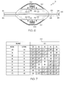
FIG. 7 is a graph of one embodiment of a display protocol for the displays of the sensor module ofFIG. 2 ; -
FIG. 8 is a simplified diagram of one embodiment of a sensor array of the sensor module ofFIG. 2 ; -
FIG. 9 is a simplified diagram of another embodiment of the sensor array of the sensor module ofFIG. 2 ; -
FIG. 10 is a simplified block diagram of one embodiment of an electrical circuit of the sensor module ofFIG. 2 ; -
FIG. 11 is a simplified flow diagram of one embodiment of a method for determining and displaying joint force data that may be executed by the sensor module ofFIG. 2 ; -
FIG. 12 is a simplified flow diagram of one embodiment of a method for displaying relative joint force data that may be executed by the sensor module ofFIG. 2 ; -
FIG. 13 is a perspective view of another embodiment of a sensor module of the system ofFIG. 1 ; -
FIG. 14 is a perspective view of another embodiment of a sensor module of the system ofFIG. 1 ; -
FIG. 15 is a perspective view of another embodiment of a sensor module of the system ofFIG. 1 ; -
FIG. 16 is a perspective view of another embodiment of a sensor module of the system ofFIG. 1 ; -
FIG. 17 is a perspective view of another embodiment of a sensor module of the system ofFIG. 1 ; -
FIG. 18 is a perspective view of another embodiment of a sensor module of the system ofFIG. 1 ; -
FIG. 19 is a perspective view of another embodiment of a sensor module of the system ofFIG. 1 ; -
FIG. 20 is a perspective view of one embodiment of a display module of the system ofFIG. 1 ; -
FIG. 21 is a plan view of the display module ofFIG. 20 ; -
FIG. 22 is a simplified block diagram of one embodiment of an electrical circuit of the display module ofFIG. 20 ; -
FIG. 23 is a simplified flow diagram of one embodiment of a method for displaying joint force data; -
FIGS. 24 to 26 are screenshots that may be displayed to a user on the display module ofFIG. 20 ; -
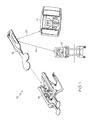
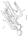
FIG. 27 is a perspective view of one embodiment of a joint distractor of the system ofFIG. 1 having the sensor module ofFIG. 2 coupled therewith; -
FIG. 28 is an elevation view of an end of the joint distractor ofFIG. 27 ; -
FIG. 29 is a top plan view of the joint distractor ofFIG. 27 ; -
FIG. 30 is a side elevation view of the joint distractor ofFIG. 27 ; -
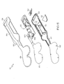
FIG. 31 is a perspective view of another embodiment of a joint distractor of the system ofFIG. 1 ; -
FIG. 32 is a simplified block diagram of one embodiment of a computer assisted surgery system of the system ofFIG. 1 ; -
FIG. 33 is a simplified flow diagram of one embodiment of a method for performing an orthopaedic surgical procedure using the computer assisted surgery system ofFIG. 32 ; -
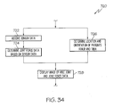
FIG. 34 is a simplified flow diagram of one embodiment of a method for determining and displaying navigation and joint force data that may be executed by the computer assisted surgery system ofFIG. 32 ; -
FIG. 35 is a simplified flow diagram of one embodiment of a method for determining and displaying flexion angle and force data of a patient's joint that may be executed by the computer assisted surgery system ofFIG. 32 ; -
FIG. 36 is a simplified flow diagram of one embodiment of a method for performing an orthopaedic surgical procedure using the system ofFIG. 1 ; -
FIG. 37 is a perspective view of a patient's joint in extension during an orthopaedic surgical procedure using the sensor module ofFIG. 2 ; -
FIG 38 is a perspective view of a patient's joint during an orthopaedic surgical procedure using the distractor and sensor module ofFIG. 20 ; -
FIG. 39 is another perspective view of a patient's joint in flexion during an orthopaedic surgical procedure using the sensor module ofFIG. 2 ; -
FIG. 40 is another perspective view of a patient's joint in extension during an orthopaedic surgical procedure using the sensor module ofFIG. 2 ; and -
FIG 41 is another perspective view of a patient's joint in flexion during an orthopaedic surgical procedure using the sensor module ofFIG. 2 . - Referring to the drawings,
FIG. 1 shows asystem 10 for determining and displaying joint forces of a patient's joint during an orthopaedic surgical procedure, which includes asensor module 12, a hand-helddisplay module 14, and ajoint distractor 16. Thesystem 10 may also include components of a computer assisted surgery system (CAOS)system 18. As discussed in more detail below, thesensor module 12 is configured to be inserted into a patient's joint and provide a visual indication of the joint forces to an orthopaedic surgeon. For example, in one embodiment, thesensor module 12 provides a visual indication of the relative or balance of the medial-lateral joint forces of a patient's knee joint. Thesensor module 12 may also be configured to transmit joint force data to the hand-helddisplay module 14 by means of awireless communication link 20 and/or the computer assistedsurgery system 18 by means of awireless communication link 22. In response, thedisplay module 14 and/or computer assistedsurgery system 18 are configured to display the joint force data, or data derived therefrom, to an orthopaedic surgeon. Additionally, during the performance of an orthopaedic surgical procedure, such as a total or partial knee arthroplasty procedure, thesensor module 12 may be coupled to thejoint distractor 16 to provide visual indication of the joint forces of the patient's joint during distraction thereof as discussed below. - Referring now to
FIGS. 2 to 10 , thesensor module 12 includes asensor housing 30 and ahandle 32 coupled to thesensor housing 30. Thesensor housing 30 is sized and shaped to be positioned in a j oint of the patient. In a preferred embodiment, thesensor housing 30 is embodied as atibial paddle 34, which is shaped to be positioned in a knee joint of the patient. However, thesensor housing 30 may be configured to be used with other joints of the patient in other embodiments as discussed in more detail below with reference toFIGS. 11 and 12 . - In use, the
tibial paddle 34 is configured to be positioned on a proximal plateau of a patient's resected tibia (see, e.g.,FIG. 29 to 33 ). As discussed in more detail below, thetibial paddle 34 may be placed in contact with the patient's tibia or may be placed on an intervening platform or other member. Additionally, thesensor module 12 may be used on the patient's left or right knee. For example, thesensor module 12 may be used on a patient's left knee using a medial surgical approach wherein thetibial paddle 34 is inserted into the patient's left knee joint through a medial capsular incision. In such position, as discussed below, thehandle 32 extends out of the medial capsular incision. Alternatively, by simply flipping or turning over thesensor module 12, themodule 12 may be used on the patient's left knee using a lateral surgical approach wherein thetibial paddle 34 is inserted into the patient's left knee joint through a lateral capsular incision. Again, in such position, thehandle 32 extends out of the lateral capsular incision. - As such, it should be appreciated that
sensor module 12 may be used on the patient's left or right knee using a medial or lateral surgical approach. For clarity of description, thesensor module 12 and thesystem 10 are described below with reference to an orthopaedic surgical procedure using a medial surgical approach (i.e., using a medial capsular incision to access the patient's joint). However, it should be appreciated that such description is equally applicable to lateral surgical approach procedures. As such, some structures are described using particular anatomical references (e.g., lateral and medial) with the understanding that such references would be flipped or switched when themodule 12 is used in a lateral surgical approach procedure. For example, a "medial side" of thetibial paddle 34 becomes a "lateral side" of thetibial paddle 34 when used in a lateral surgical approach procedure. - The
tibial paddle 34 is substantially planar and has a shape generally corresponding to the shape of the orthopaedic prosthesis to be implanted in the patient. For example, in this embodiment, thetibial paddle 34 has a shape generally corresponding to a knee prosthesis of a particular size. However, in other embodiments as discussed in more detail below, the paddle 34 (or sensor housing 30) may have a shape generally corresponding to other types of orthopaedic prostheses such as a hip prosthesis, a shoulder prosthesis, an ankle prosthesis, a spine prosthesis, or a patella prosthesis. - The
tibial paddle 34 has a curvedanterior side 36, a curvedlateral side 38, a curvedmedial side 40, and acurved posterior side 42, each shaped to approximate the shape a tibial bearing of an orthopaedic knee prosthesis. Again, as discussed above, thelateral side 38 and themedial side 40 are lateral and medial sides, respectively, in those embodiments wherein thesensor module 12 is used in a lateral surgical approach procedure. Theposterior side 42 includes aposterior notch 44 to allow thetibial paddle 34 to be positioned around the soft tissue of the patient's joint such as the posterior cruciate ligament. Additionally, in some embodiments, theposterior notch 44 may also provide a mount for other surgical devices such as a trail post for rotating mobile bearing trails. Further, in some embodiments, theposterior notch 44 may be extended or otherwise have other configurations so as to provide a mount for other orthopaedic surgical devices such as fixed and/or mobile tibial trials or the like. - The overall size of the
tibial paddle 34 may be selected based on the particular anatomical structure of the patient. For example, in some embodiments, thetibial paddle 34 may be provided in various sizes to accommodate patients of varying sizes. It should be appreciated that the general shape and size of the paddle 34 (and sensor housing 30) is designed and selected such that thepaddle 34 orhousing 30 does not significantly overhang with respect to the associated bony anatomy of the patient such that thepaddle 34 orhousing 30 nor adversely impinge the surrounding soft tissue. - The
handle 32 includes a pair ofdisplays first end 54 of thehandle 32. Asecond end 56 of thehandle 32 opposite thefirst end 54 is coupled to thetibial paddle 34. In the embodiment shown inFIG. 2 , thehandle 32 andtibial paddle 34 are substantially monolithic in structure. However, in other embodiments, thetibial paddle 34 may be removably coupled to thehandle 32 by means of a suitable connector or the like. - As shown in
FIGS. 3 and 4 , thehandle 32 extends from a side of thetibial paddle 34. In a preferred embodiment, thehandle 32 extends from the medial side 40 (which is a lateral side when thesensor module 12 is used in a lateral surgical approach procedure). It should be appreciated that because thehandle 32 extends from a side of thepaddle 34, thetibial paddle 34 may be positioned in a knee joint of a patient without the need to sublux or evert the patient's patella. That is, thetibial paddle 34 may be properly positioned between the patient's proximal tibia and distal femur with the patient's patella in the natural position. - Depending on the particular surgical approach to be used by the orthopaedic surgeon, the surgeon may flip the
sensor module 12 to the proper orientation such that thetibial paddle 34 is inserted into the patient's knee joint through the associated capsular incision. In either orientation, thehandle 32 extends out of the capsular incision and at least one of thedisplays sensor module 12 in the orientation shown inFIG. 3 such that thehandle 32 extends from the medial side of the patient's knee (through the medial capsular incision) when thetibial paddle 34 is inserted into the knee joint and thedisplay 50 is visible to the surgeon. Alternatively, if the orthopaedic surgeon is using a lateral surgical approach on a patient's left knee, the orthopaedic surgeon may position thesensor module 12 in the orientation shown inFIG. 4 such that thehandle 32 extends from the lateral side of the patient's knee (through the lateral capsular incision) when thetibial paddle 34 is inserted into the knee joint and thedisplay 52 is visible to the surgeon. - As discussed above, the
sensor module 12 is configured to assist a surgeon during the performance of an orthopaedic surgical procedure. As such, thesensor module 12 includes anouter housing 58 formed from a bio-compatible material. For example, theouter housing 58 may be formed from a bio-compatible polymer. Thesensor module 12 may be provided in sterile form for single-usage. For example, thesensor module 12 may be provided in a sterile packaging. However, in those embodiments wherein thetibial paddle 34 is removably coupled to thehandle 32, thetibial paddle 34 may be designed for single-usage and thehandle 32 may be configured to be reusable by means of an autoclaving procedure or the like. - As shown in
FIG. 5 , theouter housing 58 of thesensor module 12 includes anupper housing 60 and alower housing 62, which are coupled to each other. In some embodiments, theupper housing 60 and thelower housing 62 are mirror images of each other. Theupper housing 60 includes an uppertibial paddle housing 64 and anupper handle housing 66. Similarly, thelower housing 62 includes a lowertibial paddle housing 68 and alower handle housing 70. - The
display 50 is coupled to theend 54 of theupper housing 60 and thedisplay 52 is coupled to the 54 of thelower housing 62. As shown inFIG. 6 , thedisplays FIG. 6 , each of thedisplays light emitting diodes light emitting diodes 84 are illuminated when the medial-lateral joint forces of the patient's knee joint are approximately equal. Additionally, thelight emitting diodes 80 and/or 82 are illuminated when the medial joint force is greater than the lateral joint force of the patient's knee joint by a predetermined threshold amount and thelight emitting diodes FIG. 6 , thelight emitting diodes displays light emitting diodes 80, 82 correspond with themedial side 40 of thetibial paddle 34 and thelight emitting diodes lateral side 38 of thetibial paddle 34 regardless of the orientation (i.e., regardless of whether theupper housing 60 or thelower housing 62 is facing upwardly). - As discussed in more detail below, the
light emitting diodes light emitting diodes graph 170 inFIG. 7 . According to thedisplay protocol 170, only thelight emitting diode 88 is illuminated if the medial-lateral joint force balance is 30% medial - 70% lateral, respectively, or laterally greater. However, bothlight emitting diodes light emitting diode 86 is illuminated. If the medial-lateral joint force balance is about 45% medial - 55% lateral, respectively, bothlight emitting diodes light emitting diode 84 is illuminated. If the medial-lateral joint force balance is about 55% medial - 45% lateral, respectively, bothlight emitting diodes 82 and 84 are illuminated. If the medial-lateral joint force balance is about 60% medial - 40% lateral, respectively, only the light emitting diode 82 is illuminated. If the medial-lateral joint force balance is about 65% medial - 35% lateral, respectively, bothlight emitting diodes 80 and 82 are illuminated. Additionally, if the medial-lateral joint force balance is 70% medial - 30% lateral, respectively, or medially greater, only thelight emitting diode 80 is illuminated. In this way, a visual indication of the relative joint force balance of the patient's knee is provided to the orthopaedic surgeon. Of course, in other embodiments, other display protocols may be used to control and illuminate thedisplays - The
sensor module 12 includes asensor array 90 positioned in thetibial paddle 34 and connected to acontrol circuit 92 positioned in thehandle 32. Thesensor array 90 is "sandwiched" between theupper housing piece 60 and thelower housing piece 62. However, theupper housing piece 60 and thelower housing piece 62 are spaced apart to allow thesensor array 90 to be compressed by the joint force applied to thetibial paddle 34. For example, as shown inFIG. 6 , theupper housing 64 includes anouter rim 94 and thelower housing 66 includes anouter rim 96, which is spaced apart from theouter rim 94 of theupper housing 64 by adistance 98. When a joint force is applied to thetibial paddle 34, theouter rims sensor array 90 is compressed. - The
sensor array 90 includes a plurality of pressure sensors orsensor elements 100 configured to generate sensor signals indicative of the joint force applied to thesensor array 90. In a preferred embodiment, thepressure sensors 100 are embodied as capacitive pressure sensors, but may be embodied as other types of sensors in other embodiments. In a preferred embodiment, thepressure sensors 100 of thesensor array 90 are arranged in a particular configuration. For example, in one embodiment as shown inFIG. 8 , thesensor array 90 includes a set ofpressure sensors medial side 38 of thetibial paddle 34. Additionally, thesensor array 90 includes a set ofpressure sensors lateral side 40 of thetibial paddle 34. Thesensor array 90 also includes apressure sensor 120 positioned toward theanterior side 36 andmedial side 38 of thetibial paddle 34 and apressure sensor 122 positioned toward theanterior side 36 andlateral side 40 of thetibial paddle 34. Additionally, thesensor array 90 includes apressure sensor 124 positioned toward theposterior side 42 andmedial side 38 of thetibial paddle 34 and apressure sensor 126 positioned toward theposterior side 42 andlateral side 40 of thetibial paddle 34. Of course, in other embodiments, sensor arrays having pressure sensors arranged in other configurations may be used. In the embodiment shown inFIG. 8 , thepressure sensors distractor 16 to improve sensitivity thereto as described below with reference toFIG. 27 . - The
pressure sensors pressure sensors pressure sensors pressure sensors pressure sensors pressure sensors - In other embodiments, the
sensor array 90 may include more or fewer pressure sensors. In one particular embodiment, thesensor array 90 may include additional medial and lateral pressure sensors for each condyle of the patient's femur. For example, as shown inFIG. 9 , thesensor array 90 may include a medial-medial pressure sensor 180, a medial-lateral pressure sensor 182, a lateral-medial pressure sensor 184, and lateral-lateral pressure sensor 186. That is, thepressure sensor 180 is configured to sense or measure the medial component of the medial joint force exerted by the patient's medial femoral condyle. Similarly, thepressure sensor 182 is configured to sense or measure the lateral component of the medial joint exerted by the patient's medial femoral condyle. Thepressure sensor 184 is configured to sense or measure the medial component of the lateral joint force exerted by the patient's lateral femoral condyle. Similarly, thepressure sensor 186 is configured to sense or measure the lateral component of the lateral joint exerted by the patient's lateral femoral condyle. The particular shape and size of thepressure sensors sensor array 90. - Referring now to
FIG. 10 , thecontrol circuit 92 includes aprocessor 130 and amemory device 132. Theprocessor 130 may be embodied as any type of processor configured to perform the functions described herein. For example, theprocessor 130 may be embodied as a separate integrated circuit or as a collection of electronic devices. Additionally, the processor may be a single or multi-core processor. Although only asingle processor 130 is shown inFIG. 10 , it should be appreciated that thecontrol circuit 92 may include any number of additional processors in other embodiments. Thememory device 132 may be embodied read-only memory devices and/or random access memory devices. For example, thememory device 132 may be embodied as or otherwise include electrically erasable programmable read-only memory devices (EEPROM), dynamic random access memory devices (DRAM), synchronous dynamic random access memory devices (SDRAM), double-data rate dynamic random access memory devices (DDR SDRAM), and/or other volatile or non-volatile memory devices. Additionally, although only a single memory device is shown inFIG. 10 , in other embodiments, thecontrol circuit 92 may include additional memory devices. - The
processor 130 is communicatively coupled to thememory device 132 by means ofsignal paths 134. Thesignal paths 134 may be embodied as any type of signal paths capable of facilitating communication between theprocessor 130 and thememory device 132. For example, thesignal paths 134 may be embodied as any number of wires, printed circuit board traces, via, bus, intervening devices, and/or the like. Theprocessor 130 is also connected to thesensor array 90 by means ofsignal paths 136. Similar to signalpaths 134, thesignal paths 136 may be embodied as any type of signal paths capable of facilitating communication between theprocessor 130 and thesensor array 90 including, for example any number of wires, printed circuit board traces, via, bus, intervening devices, and/or the like. Additionally, thesignal path 136 may include a connector 138 (seeFIG. 5 ) configured to receive a plug-end 140 of thesensor array 90. - The
control circuit 92 also includes apower source 142 and associatedpower control circuitry 144. Thepower source 142 may be embodied as a number of batteries sized to fit in thesensor module 12. Thepower source 142 is electrically coupled to thepower control circuitry 144 by means ofsignal paths 146 and thepower control circuitry 144 is electrically coupled to theprocessor 130 and other devices of thecontrol circuit 92 by means ofsignal paths 148. Thesignal paths power circuitry 144 may include power control, distribution, and filtering circuitry and is configured to provide or distribute power from thepower source 142 to theprocessor 130 and other devices or components of thecontrol circuit 92. - The
control circuit 92 also includes user controls 150 communicatively coupled to theprocessor 130 by means ofsignal paths 152. The user controls 150 are embodied as power buttons 154 (seeFIG. 6 ) located on thedisplays sensor module 12 on. However, in this embodiment, thecontrol circuit 92 is configured to prevent or otherwise limit the ability of the user from turning off thesensor module 12 by means of thepower buttons 154 or other controls after thesensor module 12 has been turned on. That is, once turned on, thecontrol circuit 92 is configured to remain on until thepower source 142 is depleted. Such a configuration ensures that thesensor module 12 is used during a single orthopaedic surgical procedure and is not otherwise reusable in multiple procedures. - The
signal paths 152 are similar to thesignal paths 134 and may be embodied as any type of signal paths capable of facilitating communication between the user controls 150 and theprocessor 130 including, for example any number of wires, printed circuit board traces, via, bus, intervening devices, and/or the like. - The
control circuit 92 also includesdisplay circuitry 156 for driving and/or controlling thedisplays display circuitry 156 is communicatively coupled to theprocessor 130 by means ofsignal paths 158 and to thedisplays signal paths 160. Similar to thesignal paths 134 discussed above, thesignal paths processor 130 anddisplay circuitry 156 and thedisplay circuit 156 and displays 50, 52, respectively. For example, thesignal paths displays light emitting diodes - In some embodiments, the
sensor module 12 is configured to transmit force data to thedisplay module 14 and/or computer assisted orthopaedic surgery (CAOS)system 18. In such embodiments, the control circuit includestransmitter circuitry 162 and anantenna 164. Thetransmitter circuitry 162 is communicatively coupled to theprocessor 130 by means ofsignal paths 166 and to theantenna 164 by means ofsignal paths 168. Thesignal paths transmitter circuitry 162 and theprocessor 130 andantenna 164, respectively. For example, similar to thesignal paths 134, thesignal paths transmitter circuitry 162 may be configured to use any type of wireless communication protocol, standard, or technologies to transmit the joint force data to thedisplay module 14 and/or computer assisted orthopaedic surgery (CAOS)system 18. For example, thetransmitter circuitry 162 may be configured to use a wireless networking protocol, a cellular communication protocol such as a code division multiple access (CDMA) protocol, a Bluetooth protocol, or other wireless communication protocol, standard, or technology. - Referring now to
FIGS. 11 and 12 , thecontrol circuit 92 is configured in use to execute amethod 200 for determining joint force data of a patient's joint and providing a visual indication of the medial-lateral balance of the patient's joint force. Themethod 200 begins withblock 202 in which thecontrol circuit 92 is initialized. For example, inblock 202, thecontrol circuit 92 may perform any number of system checks, clear any registers of theprocessor 130, and/or perform other initialization and/or integrity checks. Additionally, in some embodiments, thecontrol circuit 92 is configured to perform a handshaking routine inblock 132 with the hand-helddisplay device 14 and/or the computer assisted orthopaedic surgery (CAOS)system 18. During this handshaking routine, thecontrol circuit 92 and the hand-helddisplay device 14 and/or the computer assisted orthopaedic surgery (CAOS)system 18 may be configured to determine communication protocols and/or otherwise establish any type of communication procedures for transmitting the joint force data from thesensor module 12 to thedevice 14 orsystem 18. - In
block 206, thecontrol circuit 92 receives the sensor signals or data from thesensor array 90. As discussed above, thesensor array 90 generates sensor signals indicative of a joint force applied to thetibial paddle 34 when thepaddle 34 is positioned in the knee joint of a patient. Inblock 208, theprocessor 130 of thecontrol circuit 92 determines joint force data based on the sensor signals received from thesensor array 90. The joint force data is indicative of the joint force of the patient's knee. In some embodiments, the joint force data may be embodied as specific joint force values such as a medial joint force value, a lateral joint force value, an anterior joint force value, and/or a posterior joint force value, each force being determined in Newtons or similar force measurement unit. In such embodiments, the medial joint force may be determined based on the sensor signals from thepressure sensors pressure sensors medial pressure sensors lateral pressure sensors medial pressure sensors lateral sensors block 210 thecontrol circuit 92 controls or otherwise activates thedisplays block 208. For example, in embodiments wherein one or more specific joint forces are determined, theprocessor 130 may display the determine joint forces or indicia thereof on thedisplays - Additionally or alternatively, the
control circuit 92 may be configured to determine the relative medial-lateral joint force balance and display indicia of such medial-lateral balance on thedisplays blocks FIG. 12 , thecontrol circuit 92 may execute amethod 220 for determining the relative medial-lateral joint forces of the patient's joint. Inblock 222, thecontrol circuit 92 determines medial joint force data based on the sensor signals received from thepressure sensors block 224, thecontrol circuit 92 determines lateral joint force data based on the sensor signals received from thepressure sensors blocks - In
block 226, thecontrol circuit 92 determines the relative medial-lateral balance of the joint force of the patient's joint. To do so, thecontrol circuit 92 compares the medial force data and the lateral force data. For example, in one embodiment, thecontrol circuit 92 is configured to determine a total force value by summing the medial force data and the lateral force data. Thecontrol circuit 92 subsequently determines a medial percentage value by dividing the medial force data by the total force value and a lateral percentage value by dividing the lateral force data by the total force value. As such, if the medial and lateral forces of a patient's joint are balanced, the medial percentage value would be determined to be about 50% and the lateral percentage value would be determined to be about 50%. Of course, in some embodiments, thecontrol circuit 92 may be configured to determine only one of the medial and lateral percentage values, the remaining one being known or determined by simple subtraction from 100%. - In
block 228, thecontrol circuit 92 activates or controls thedisplays displays control circuit 92 is configured to activate or illuminate one or more of the light emitting diodes to provide a visual indication of the medial-lateral balance of joint forces. Thecontrol circuit 92 may use any display protocol or pattern of illumination of the light emitting diodes that provides an appropriate indication to the orthopaedic surgeon of such joint forces. - For example, in one particular embodiment, the
control circuit 92 is configured to control thedisplays display protocol 170 discussed above with reference toFIG. 7 . In such embodiments, thecontrol circuit 92 is configured to illuminate the centrally locatedlight emitting diode 84 of thedisplays control circuit 92 is configured to illuminate the centrally locatedlight emitting diode 84 and the laterallight emitting diode 86 if the medial-lateral balance of the joint forces is about 45% medial - 55% lateral, respectively. Thecontrol circuit 92 is configured to illuminate the laterallight emitting diodes control circuit 92 is configured to illuminate the lateral-mostlight emitting diode 88 if the medial-lateral balance of the joint forces is about 30% medial - 70% lateral (or more lateral), respectively. Similarly, thecontrol circuit 92 is configured to illuminate the centrally locatedlight emitting diode 84 and the medial light emitting diode 82 if the medial-lateral balance of the joint forces is about 55% medial - 45% lateral, respectively. Thecontrol circuit 92 is configured to illuminate the laterallight emitting diodes 80, 82 if the medial-lateral balance of the joint forces is about 65% medial - 35% lateral, respectively. Additionally, thecontrol circuit 92 is configured to illuminate the medial-mostlight emitting diode 80 if the medial-lateral balance of the joint forces is about 70% medial - 30% lateral (or more medial), respectively. - In this way,
sensor module 12 provides a visual indication to the orthopaedic surgeon of the relative medial and lateral forces of the patient's joint. As discussed in more detail below, the orthopaedic surgeon can perform balancing procedures on the patient's knee joint while monitoring the current balance of the medial and lateral forces by means of thedisplays sensor module 12 includes adisplay - Referring back to
FIG. 12 , in addition to activating thedisplays block 210, thesensor module 12 may be configured to transmit the joint force data inblock 212. As discussed above, thesensor module 12 may transmit the joint force data to the hand-helddisplay 14 and/or computer assisted orthopaedic surgery (CAOS)system 18 inblock 212. The transmitted joint force data may be embodied as the specific joint forces measured in Newtons, for example, or may be representations thereof. For example, the sensor signals received from thesensor array 90 or electrical representations of the levels of such signals may be transmitted inblock 212. Regardless, thesensor module 12 is configured to transmit joint force data that is indicative of the joint forces of the patient's knee joint to thedisplay 14 and/or thesystem 18 inblock 212. - Referring now to
FIGS. 13 and14 , in other embodiments, thehandle 32 andtibial paddle 34 may be coupled to each other at other orientations and/or by means of other intervening structures. For example, as shown inFIG. 13 , thesensor module 12 may be embodied as amodule 232 in which thehandle 32 is coupled to theanterior side 36 of thetibial paddle 34 is some embodiments. In such embodiments, thehandle 32 extends anteriorly from the patient's knee joint (e.g., through an anterior capsular incision) when thetibial paddle 34 is inserted therein. Alternatively, as shown inFIG. 14 , thesensor module 12 may be embodied as amodule 232 in which thehandle 32 and thetibial paddle 34 are coupled to each other by means of awire 234. Thewire 234 may be embodied as a plurality of wires, cables, or other interconnects that communicatively couple thesensor array 90 positioned in thetibial paddle 34 to thecontrol circuit 92 located in thehandle 32. Although thewire 234 is shown coupled to theposterior side 36 of thetibial paddle 34 in the embodiment ofFIG. 14 , it should be appreciated that thewire 234 may be coupled to thetibial paddle 34 on thelateral side 38, themedial side 40, or theposterior side 42 in other embodiments. - Referring now to
FIGS. 15 to 19 , thesensor module 12 may be configured for use with joint's other than the patient's knee joint. For example, in one embodiment, thesensor module 12 is embodied as asensor module 250, which includes asensor housing 252 and ahandle 254 connected to thesensor housing 252 by means of anelongated neck 256. Thehandle 254 is similar to thehousing 32 of thesensor module 12 and includes thecontrol circuit 92 positioned therein and displays 50, 52 coupled to anend 258 of thehandle 254. Thesensor housing 252, however, is configured to be positioned in a ball-and-socket joint of the patient such as the patient's hip joint or shoulder joint. As such, thesensor housing 252 is substantially "cup-shaped" and includes a concaveupper housing piece 260 and a corresponding convexlower housing piece 262. The concaveupper housing piece 260 defines aninner recess 260, which may receive a portion of an orthopaedic prosthetic or prosthetic trial or an end of a patient's natural or prosthetic bone during the performance of the orthopaedic surgical procedure. Similar to thesensor housing 30, thesensor array 90 is positioned in thesensor housing 252 and is configured to generate sensor signals indicative of the joint forces of the patient's relative joint. - In some embodiments, the
sensor housing 252 may be detached from thehandle 254, but communicatively coupled therewith, to improve the ease of use of thesensor module 250 with particular joints. For example, as shown inFIG. 12 , thesensor housing 252 and thehandle 254 may be detached from each other but communicatively coupled by means of a wire or plurality ofwires 266. That is, thesensor array 90 positioned in thesensor housing 252 is communicatively coupled with thecontrol circuit 90 positioned in thehandle 254. - In another embodiment as shown in
FIG. 17 , thesensor module 12 may be embodied as asensor module 270 configured to be used with a spinal joint of the patient. Thesensor module 270 includes aspinal paddle 272 coupled to thehandle 254 by means of theelongated neck 256. Thespinal paddle 272 is configured to be inserted between the vertebra of the patient's spine. In this embodiment, thepaddle 272 has a substantial curricular shape, but may have other shapes in other embodiments. Thespinal paddle 272 includes anotch 274 configured to receive a portion of the patient's spinal cord such that thespinal paddle 272 may be fully inserted into the patient's spine. A sensor array is included in thespinal paddle 272 to measure or sense the joint force of the patient's spine. The spinal senor array may have any number of pressure sensors arranged in a configuration similar to thesensor array 90 discussed above or in another configuration. - Additionally, in some embodiments as shown in
FIG. 18 , thesensor module 12 may be embodied as asensor module 280 configured to be used with the patella of a patient's knee joint to measure patellofemoral forces. Similarly to thesensor module 270 discussed above with reference toFIG. 17 , thesensor module 280 includes apatella paddle 282 coupled to thehandle 254 by means of theelongated neck 256. Thepatella paddle 282 is configured to be inserted between the patient's patella and femur. In this embodiment, thepaddle 282 has a substantial oval shape, but may have other shapes in other embodiments. A sensor array is included in thepatella paddle 282 to measure or sense the force exerted by the patient's patella on the patient's femur. The patella senor array may have any number of pressure sensors arranged in a configuration similar to thesensor array 90 discussed above or in another configuration. - Referring now to
FIG. 19 , in another embodiment, thesensor module 12 is embodied as asensor module 290 configured to be used with an ankle joint of the patient. Thesensor module 290 includes anankle sensor housing 292 coupled to handle 254 by means of awire 294. Thewire 294 may be embodied as a plurality of wires, cables, and/or other interconnects to communicatively couple theankle sensor housing 292 and thecontrol circuit 92 located in thehandle 254. Theankle sensor housing 292 is configured to be inserted in an ankle joint of the patient. In this embodiment, theankle sensor housing 292 is shaped as a half-cylinder, but may have other shapes in other embodiments. A sensor array is included in theankle sensor housing 292 to measure or sense the patient's ankle joint force. The ankle senor array may have any number of pressure sensors arranged in a configuration similar to thesensor array 90 discussed above or in another configuration. - Referring now to
FIGS. 20 to 26 , the hand-helddisplay module 14 includes ahousing 300 sized to be held in the hands of an orthopaedic surgeon and used during the performance of an orthopaedic surgical procedure. In this way, thedisplay module 14 is configured to be mobile. Thedisplay module 14 also includes adisplay 302 coupled to anupper side 304 of thehousing 300. A plurality ofuser input buttons upper side 304 of thehousing 300 below thedisplay 302. Thedisplay module 14 also includes apower button 312. In this embodiment ofFIGS. 20 to 26 , thepower button 312 is positioned below the row ofinput buttons buttons display module 14 may include a power-onindicator 314 and abattery state indicator 316 located on theupper side 304 of thehousing 300. - As discussed above, the hand-held
display module 14 is configured to be used with thesensor module 12 to receive joint force data form themodule 12 and display indicia on thedisplay 302 indicative of the joint forces of the patient's joint. Similar to thesensor module 12, thedisplay module 14 may be configured to determine the relative medial-lateral and/or anterior-posterior balance of the patient's joint forces and display indicia of such balances on thedisplay 302. Additionally, thedisplay module 14 may be configured to determine the anterior-posterior balance of the patient's joint forces and display indicia of such balances on thedisplay 302. Further, as discussed in more detail below, thedisplay module 14 may be configured to determine the specific joint force values (e.g., the medial and lateral joint forces) and display such force values on thedisplay 302. That is, in addition to an indication of the joint forces relative to each other, the hand-helddisplay module 14 may calculate or otherwise determine the magnitude of the joint force values as measured in a suitable unit of force such as Newtons. Additionally, thedisplay module 14 may also be configured to perform other functions such as store screenshots and data of the patient's joint forces as displayed on thedisplay 302 and download such data to other devices. - As shown in
FIG. 22 , the hand-helddisplay module 14 includes acontrol circuit 320 positioned in thehousing 300. Thecontrol circuit 320 includes aprocessor 322 and amemory device 324. Theprocessor 322 may be embodied as any type of processor configurable to perform the functions described herein. For example, theprocessor 322 may be embodied as a separate integrated circuit or as a collection of electronic devices. Additionally, the processor may be a single or multi-core processors. Although only asingle processor 322 is shown inFIG. 22 , it should be appreciated that in other embodiments, thecontrol circuit 320 may include any number of additional processors. Thememory device 324 may be embodied read-only memory devices and/or random access memory devices. For example, thememory device 324 may be embodied as or otherwise include electrically erasable programmable memory devices (EEPROM), dynamic random access memory devices (DRAM), synchronous dynamic random access memory devices (SDRAM), double-data rate dynamic random access memory devices (DDR SDRAM), and/or other volatile or non-volatile memory devices. Additionally, although only a single memory device is shown inFIG. 22 , in other embodiments, thecontrol circuit 320 may include additional memory devices. - The
processor 322 is communicatively coupled to thememory device 324 by means ofsignal paths 326. Thesignal paths 326 may be embodied as any type of signal paths capable of facilitating communication between theprocessor 322 and thememory device 324. For example, thesignal paths 326 may be embodied as any number of wires, printed circuit board traces, via, bus, intervening devices, and/or the like. - The
processor 322 is also communicatively coupled to theuser input buttons signal paths 328 and to thepower indicator 314 by means of signal paths 344. Similar to signalpaths 326, thesignal paths 328, 344 may be embodied as any type of signal paths capable of facilitating communication between theprocessor 322 and theuser input buttons power indicator 314, respectively. For example, thesignal paths 328, 344 may include any number of wires, printed circuit board traces, via, bus, intervening devices, and/or the like. Theuser input buttons display 302. - The
control circuit 320 also includes an externalpower input circuitry 330, arechargeable power source 332 such as a rechargeable battery or the like, andpower circuitry 334. The externalpower input circuitry 330 is configured to receive a plug of a charger such as a "wall charger" and is communicatively coupled to therechargeable power source 332 by means ofsignal paths 336. Therechargeable power source 332 is communicatively coupled to thepower circuitry 334 by means ofsignal paths 338. Thepower circuitry 334 is communicatively coupled to theprocessor 332 by means ofsignal paths 340 and to thepower button 312 by means ofsignal paths 342. Thesignal paths power circuitry 334 may include power control, distribution, and filtering circuitry and is configured to provide or distribute power therechargeable power source 332 to theprocessor 322 and other devices or components of thecontrol circuit 320. - The
control circuit 320 also includesdisplay circuitry 346 for driving and/or controlling the display 392. Thedisplay circuitry 346 is communicatively coupled to theprocessor 322 by means ofsignal paths 348 and to thedisplay 302 by means ofsignal paths 350. Thesignal paths processor 322 anddisplay circuitry 346 and thedisplay circuit 346 anddisplay 302, respectively. For example, thesignal paths - As discussed above, the hand-held
display module 14 is configured to receive joint force data from thesensor module 12. As such thecontrol circuit 320 includesreceiver circuitry 352 and anantenna 354. Thereceiver circuitry 352 is communicatively coupled to theprocessor 322 by means ofsignal paths 356 and to theantenna 354 by means ofsignal paths 358. Thesignal paths receiver circuitry 352 and theprocessor 322 and theantenna 354, respectively. For example, thesignal paths receiver circuitry 352 may be configured to use any type of wireless communication protocol, standard, or technologies to receive the joint force data from thesensor module 12. For example, as discussed above in relation to thesensor module 12, thedisplay module 14 may be configured to a wireless networking protocol, a cellular communication protocol such as a code division multiple access (CDMA) protocol, a Bluetooth protocol, or other wireless communication protocol, standard, or technology to communicate with thesensor module 12. - The
control circuit 320 also includes a universal serial bus (USB)interface 360. TheUSB interface 360 is communicatively coupled to theprocessor 322 by means ofsignal paths 362, which may be embodied as any type of signal paths capable of facilitating communication between theUSB interface 360 and theprocessor 322. For example, thesignal paths 362 may be embodied as any number of wires, printed circuit board traces, via, bus, intervening devices, and/or the like. TheUSB interface 360 may be used to download data, such as joint force data or screenshot data, from thedisplay module 14 to another device such as a computer. Additionally, theUSB interface 360 may be used to update the software or firmware of thecontrol circuit 320. - Referring now to
FIGS. 23 to 26 , in use, thecontrol circuit 320 is configured to execute amethod 400 for determining and displaying joint force data related to a patient's joint to an orthopaedic surgeon. Themethod 400 begins withblock 402 in which thecontrol circuit 320 is initialized. For example, inblock 402, thecontrol circuit 320 may perform any number of system checks, clear any registers of theprocessor 322, and/or perform other initialization and/or integrity checks. Additionally, in some embodiments, thecontrol circuit 320 is configured to perform a handshaking routine inblock 404 with thesensor module 12. During this handshaking routine, thecontrol circuit 320 and thesensor module 12 may be configured to determine communication protocols and/or otherwise establish any type of communication procedures for transmitting the joint force data from thesensor module 12 to thedevice module 14. - In
block 406, thecontrol circuit 320 receives the joint force data from thesensor module 12. As discussed above, the joint force data is indicative of the joint force of the patient's knee as indicated by the sensor signals generated by thesensor array 90 of thesensor module 12. Inblock 408, thecontrol circuit 320 determines a medial joint force value and a lateral joint force value based on the joint force data received inblock 406. The medial joint force value is based on the sensor signals received from thepressure sensors pressure sensors block 410, thecontrol circuit 320 determines an average medial/lateral force value based on the medial joint force value and the lateral joint force value determined inblock 408. The medial joint force value, the lateral joint force value, and the average joint force value are subsequently displayed on thedisplay 302 inblock 412. For example, as shown in thescreenshots FIGS. 24, 25 , and26 , the medialjoint force value 430 is displayed toward a medially designatedside 460 of thedisplay 302, the lateraljoint force value 432 is displayed toward a laterally designatedside 462 of thedisplay 302, and theaverage force value 434 is displayed toward a posterior designatedside 464. - In blocks 414, 416, the
control circuit 320 determines which mode the orthopaedic surgeon has selected. In this embodiment, the orthopaedic surgeon may select a first mode in which indicia of only the medial-lateral balance of the patient's joint forces is displayed on thedisplay 302 or a second mode in which may indicia of the medial-lateral and the anterior-posterior balance of the patient's joint forces is displayed in thedisplay 302. The user may switch between the two modes by selecting the appropriate user input buttons 306,308,310. - If the orthopaedic surgeon has selected the medial-lateral only mode, the
method 400 advances to block 418 in which indicia of the medial-lateral balance of the joint forces of the patient's knee are displayed on thedisplay 302. To do so, as shown inFIG. 24 , ascreen display 450 is presented on thedisplay 302 of thedisplay module 14. Thescreen display 450 includes abackground image 470, which in this embodiment is an image of the proximal end of a resected tibia. Thecontrol circuit 320 displays abalance bar 472 on thebackground image 470 and anicon 474 on thebalance bar 472 in a position that indicates the relative medial-lateral balance of the joint forces of the patient's joint. For example, in thescreen display 450, theicon 474, which is embodied as a rounded rectangle, is displayed on thebalance bar 472 toward thelateral side 462 of the screen display 450 (i.e., the side of thedisplay 302 corresponding to the lateral side of the resectedtibia image 470, which corresponds in this embodiment to the right side of the display 302). Such positioning indicates that the lateral force component of the total joint force of the patient's knee joint is greater than the medial joint force component. The further way theicon 474 is located from the centre of thebalance bar 472, the greater the respective medial or lateral force component. In some embodiments, thebalance bar 472 may be calibrated to provide an indication of the numerical balance between the medial-lateral forces. Additionally, in some embodiments, thebackground image 470 includes an "balanced"icon 476, embodied in this embodiment as a rounded rectangular outline, positioned on thebackground image 470 such that when theicon 474 is located within the boundaries of theicon 476, the medial joint force and the lateral joint force of the patient's knee are balanced or within a predetermined threshold of each other. - If, however, the orthopaedic surgeon has selected the medial-lateral and anterior-posterior mode, the
method 400 advances to block 420 in which indicia of the medial-lateral and anterior-posterior balance of the joint forces of the patient's knee are displayed on thedisplay 302. To do so, as shown inFIG. 25 , ascreen display 452 is presented on thedisplay 302 of thedisplay module 14. Thescreen display 450 includes thebackground image 470 on which thebalance bar 472, which in this embodiment is an image of the proximal end of a resected tibia. Thecontrol circuit 320 displays abalance bar 472 andicon 474 are displayed. Again, the position of theicon 474 on thebalance bar 472 indicates the relative medial-lateral balance of the joint forces of the patient's joint. In addition, however, amedial end 480 of thebalance bar 472 and alateral end 482 of thebalance bar 472 are positioned based on the corresponding anterior-posterior balance. For example, themedial end 480 of thebalance bar 472 is positioned toward theposterior side 464 of thedisplay 302 or theanterior side 466 of thedisplay 302 based on the anterior-posterior balance of the medial joint force. As discussed above, the anterior posterior balance of the medial joint force may be determined based on the sensor signals from thepressure sensors pressures lateral end 482 of thebalance bar 472 is positioned toward theposterior side 464 of thedisplay 302 or theanterior side 466 of thedisplay 302 based on the anterior-posterior balance of the lateral joint force. As discussed above, the anterior posterior balance of the lateral joint force may be determined based on the sensor signals from thepressure sensors pressures - In the
screen display 452 shown inFIG. 26 , themedial end 480 of thebalance bar 472 is positioned toward theanterior side 466 of thedisplay 302 and thelateral end 482 of thebalance bar 472 is positioned toward theposterior side 464 of thedisplay 302. Such positioning indicates that the anterior force component of the medial force component is greater than the posterior force component of the medial force component and that the posterior force component of the lateral force component is greater than the anterior force component of the lateral force component. The further way the ends 480, 482 are from the anterior-posterior centre, the greater the respective anterior or posterior force component. - Referring back to
FIG. 23 , once the appropriate indicia of the joint force balances have been displayed on thedisplay 302, thecontrol circuit 320 determines whether the orthopaedic surgeon would like to take a snapshot of the current display inblock 422. The orthopaedic surgeon may take a screenshot of thedisplay 302 by selecting the appropriateuser input button memory device 324 inblock 424 and may be subsequently downloaded from thedisplay module 14. - When a screenshot is stored, an
icon 484 appears in the upper right corner of thedisplay 302. Theicon 484 displays the average force value that was measured on the respective stored screenshot. Any number oficons 484 may be displayed on thedisplay 302 to indicate corresponding stored screenshots. Additionally, although only a select number oficons 484 may be displayed on thedisplay 302, thecontrol circuit 320 may be configured to store any number of screenshots. In addition to theicon 484, when a screenshot is stored, a correspondingvertical balance line 486 is displayed on thedisplay 302. Thebalance line 486 provides a visual indication of the medial-lateral balance of the joint forces displayed in the associated stored screenshot. Further, if the orthopaedic surgeon has selected the medial-lateral and anterior-posterior mode, an anterior-posterior balance line 488 is displayed on thedisplay 302. Thebalance line 488 provides a visual indication of the anterior-posterior balance of the medial and lateral forces of the patient's knee joint displayed in the associated stored screenshot. - Referring now to
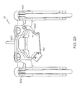
FIGS. 27 to 30 , as discussed above, thesensor module 12 may be coupled to thejoint distractor 16 during the performance of an orthopaedic surgical procedure. Thejoint distractor 16 includes acradle 500 sized and configured to receive thesensor module 12, afirst distractor component 502 movably coupled to aside 504 of thecradle 500, and asecond distractor component 506 movably coupled to aside 508 of thecradle 500 opposite theside 504. As shown inFIG. 28 , thecradle 500 includes anopening 509 having a shape corresponding to the cross-sectional shape of thehandle 32 of thesensor module 12. Thesensor module 12 may be coupled to thejoint distractor 16 by sliding thesensor module 12 handle-first into thecradle 500. Thecradle 500 includes alocking mechanism 510 that is operable to lock thesensor module 12 in thecradle 500. - As shown in
FIG. 29 , each of thedistractor components bar corresponding slot 516, 518 of thecradle 500. Thedistractor component direction 520 with respect to thecradle 500 by sliding the respective mountingbars slots 516, 518 of thecradle 500. As such, eitherdistractor component other component distractor components sensor housing 30 of thesensor module 12, the shape and size of the patient's knee, and/or other criteria. In some embodiments, as shown inFIG. 29 , the mountingbars respective distractor component windows cradle 500. When thedistractor components bars mechanisms distractor components cradle 500. - As shown in
FIG. 30 , eachdistractor component paddle set handles distractor component 502 includes atibial paddle 538 and afemoral paddle 540. Similarly, the paddle set 532 of thedistractor component 504 includes atibial paddle 542 and afemoral paddle 544. Thehandles 534 may be operated to move thefemoral paddle 540 with respect to the tibial paddle 538 (e.g., upwardly from the tibial paddle 538). Similarly, thehandles 536 may be operated to move thefemoral paddle 544 with respect to the tibial paddle 542 (e.g., upwardly from the tibial paddle 538). The tibial paddles 538, 542 and thefemoral paddles springs handles handles locking mechanism handles tibial paddles femoral paddles - In use, the
sensor module 12 is positioned in thecradle 500 and secured in place by means of thelocking mechanism 510. Depending on which knee of the patient will be operated on, thedistractor components tibial paddle 34 of thesensor module 12 as shown inFIG. 20 . It should be appreciated that the tibial paddles 538, 542 have a substantially circular shape generally corresponding to the circular orientation of thepressure sensor pressure sensors joint distractor 16 andsensor module 12 may then be inserted into the patient's joint (e.g., between the proximal end of the patient's tibia and the distal end of the patient's femur). Thejoint distractor 16 may be subsequently used to distract the patient's joint and, in response to the joint force applied to thetibial paddle 34, thesensor module 12 displays the medial-lateral balance of the joint forces of the joint at the selected degree of distraction. In this way, an orthopaedic surgeon may use thedistractor 16 andsensor module 12 to adjust and monitor the relative joint forces of the patient's joint during the performance of the orthopaedic surgical procedure. - In the embodiment shown in
FIGS. 27 to 30 , thefemoral paddles FIG. 30 ). As such, thefemoral paddles FIG. 31 , thedistractor 16 may include a four-bar linkage 272 or other mechanism configured such that thefemoral paddles femoral paddles femoral paddles distractor components cradle 500 may be coupled and, in other embodiments, thecradle 500 may be coupled to other types of distractor components configured to operate in manners similar to or different from thedistractor components - Referring now to
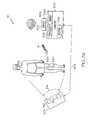
FIGS. 32 to 35 , thesensor module 12 may be configured in some embodiments for use with the computer assisted orthopaedic surgery (CAOS)system 18. In such embodiments, thesensor module 12 is configured to transmit the joint force data to thesystem 18. As shown inFIG. 32 , the computer assisted orthopaedic surgery (CAOS)system 18 includes acomputer 600, adisplay 602, and acamera unit 604. Thecomputer 600 is communicatively coupled to thedisplay 602 by means ofsignal paths 606 and to thecamera unit 604 by means ofsignal paths 608. Thesignal paths computer 600 and thedisplay 602 and thecomputer 600 and thecamera unit 604, respectively. For example, the signal paths may be embodied as any number of wires, printed circuit board traces, via, bus, intervening devices, and/or the like. - The
display 602 may be embodied as any type of device such as a liquid crystal display monitor, a cathode ray tube (CRT) display monitor, or the like. Additionally, in some embodiments, thedisplay 602 may be embodied as a "heads-up" display. In such embodiments, thesignal path 606 may be embodied as a wired or wireless signal path. Thecamera unit 604 includes two ormore cameras 610, which are positioned such thatreflective arrays 620 coupled to the relevant bones of apatient 612 are in the field ofview 614 of thecameras 610. - The
computer 600 includes aprocessor 622, amemory device 624, and a receiver orreceiver circuitry 626. Theprocessor 622 may be embodied as any type of processor configurable to perform the functions described herein. For example, theprocessor 622 may be embodied as a separate integrated circuit or as a collection of electronic devices. Additionally, the processor may be a single or multi-core processors. Although only asingle processor 622 is shown inFIG. 32 , it should be appreciated that in other embodiments, thecomputer 600 may include any number of additional processors. Thememory device 624 may be embodied read-only memory devices and/or random access memory devices. For example, thememory device 624 may be embodied as or otherwise include electrically erasable programmable memory devices (EEPROM), dynamic random access memory devices (DRAM), synchronous dynamic random access memory devices (SDRAM), double-data rate dynamic random access memory devices (DDR SDRAM), and/or other volatile or non-volatile memory devices. Additionally, although only a single memory device is shown inFIG. 32 , in other embodiments, thecomputer 600 may include additional memory devices. - The
receiver circuitry 626 may be configured to use any type of wireless communication protocol, standard, or technologies to receive the joint force data from thesensor module 12. For example, as discussed above in relation to thesensor module 12, thecomputer 600 may be configured to communicate using a wireless networking protocol, a cellular communication protocol such as a code division multiple access (CDMA) protocol, a Bluetooth protocol, or other wireless communication protocol, standard, or technology to communicate with thesensor module 12. - In use, the computer assisted orthopaedic surgery (CAOS)
system 18 is configured to provide surgical navigation by tracking and displaying the position of the patient's relevant bony anatomy (e.g., the patient's tibia and femur) to which thereflective arrays 620 are coupled and provide an amount of surgical procedure walk-through. Additionally, the computer assisted orthopaedic surgery (CAOS)system 18 is configured to receive the joint force data from thesensor module 12 and display the joint force data or other indicia of the joint forces of the patient's joint on thedisplay 602. - To do so, the
computer 600 may execute amethod 700 for performing an orthopaedic surgical procedure as shown inFIG. 33 . Themethod 700 begins withblock 702 in which thesystem 18 is initialized. For example, inblock 702, thecomputer 600 may perform any number of system checks, clear any registers of theprocessor 622, and/or perform other initialization and/or integrity checks. Additionally, any number of settings, preferences, and calibrations of theCAOS system 18 may be established and performed inblock 702. For example, the video settings of thedisplay 602 may be selected, the language displayed by thecomputer 600 may be chosen, and the touch screen of thedisplay device 602, if applicable, may be calibrated inblock 702. - In
block 704, the selections and preferences of the orthopaedic surgical procedure are chosen by the surgeon. Such selections may include the type of procedure that is to be performed (e.g., a total knee arthroplasty), the type of orthopaedic implant that will be used (e.g., make, model, size, fixation type, etc.), the sequence of operation (e.g., the tibia or the femur first), and the like. Once the orthopaedic surgical procedure has been set up inblock 704, the bones of the patient are registered inblock 706. To do so, thereflective arrays 620 are coupled with the relevant bones of the patient (e.g., the tibia and femur of the patient). Additionally, the contours of such bones are registered using an appropriate registration tool. To do so, a pointer end of such tool is touched to various areas of the bones to be registered. In response to the registration, thecomputer 600 displays rendered images of the bones wherein the location and orientation of the bones are determined based on the reflective arrays coupled therewith and the contours of the bones are determined based on the registered points. Additionally, one or more surgical tools may be registered with the computer assisted orthopaedic surgery (CAOS) system inblock 706. - Once the pertinent bones have been registered in
block 706, thecomputer 600, in cooperation with thecamera unit 604, displays the images of the surgical steps of the orthopaedic surgical procedure and associated navigation data (e.g., location of surgical tools) inblock 708. To do so, theprocess step 708 may include any number of sub-steps in which each surgical procedure step is displayed to the orthopaedic surgeon in sequential order along with the associated navigational data. Additionally, inblock 710 thecomputer 600 receives joint force data from thesensor module 12. As discussed above, the joint force data is indicative of the joint force of the patient's knee as indicated by the sensor signals generated by thesensor array 90 of thesensor module 12. - In
block 712, thecomputer 600 displays the joint force data or other data derived therefrom that is indicative of the joint forces of the patient's joint on thedisplay 602. Thecomputer 600 may be configured to determine any one or more joint force values based on the joint force data inblock 712. For example, similar to the hand-helddisplay module 14, thecomputer 600 may be configured to determine a medial joint force value and a lateral j oint force value based on the joint force data received inblock 710. Again, such medial joint force value is based on the sensor signals received from thepressure sensors pressure sensors computer 600 may also determine an average medial/lateral force value based on the medial joint force value and the lateral joint force value. In such embodiments, the medial joint force value, the lateral joint force value, and the average joint force value are subsequently displayed on thedisplay 602 inblock 712. In addition, thecomputer 600 may be configured to determine the medial-lateral and/or anterior-posterior balance of the joint forces based on the joint force data and display indicia of joint force balance on thedisplay 602 in a manner similar to the hand-helddisplay module 14. For example, thecomputer 600 may present displays similar to thedisplays FIGS. 24, 25 , and26 , respectively inblock 412. - In some embodiments, the computer assisted orthopaedic surgery (CAOS)
system 18 may be configured to determine and display joint force data on thedisplay 602 in association with the navigation data. For example, thecomputer 600 may execute amethod 720 for displaying joint force data in association with navigation data as shown inFIG. 34 . Themethod 720 includes ablock 722 in which thecomputer 600 receives joint force data from thesensor module 12. Again, the joint force data is indicative of the joint force of the patient's knee as indicated by the sensor signals generated by thesensor array 90 of thesensor module 12. Inblock 724, thecomputer 600 determines the medial, lateral, and/or average joint force values based on the joint force data received inblock 722. - Contemporaneously with the determination of the joint force values in
block 722, thecomputer 600 determines the location and orientation of the patient's relevant bones, such as the patient's femur and tibia in those embodiments wherein the patient's knee is undergoing an orthopaedic surgical procedure, inblock 724. Subsequently, inblock 728, thecomputer 600 displays the joint force values determined inblock 722 and the image of the knee joint inblock 728. As such, thecomputer 600 may be used to display, for example, the flexion and extension gaps of the medial and lateral condyles of the patient's knee and contemporaneously display the associated medial, lateral, and/or average joint force values of the patient's knee. By monitoring the flexion and extension gaps and the associated joint force values, the orthopaedic surgeon may determine the appropriate amount of gap or joint force for a particular orthopaedic procedure. - Additionally, in some embodiments, the
computer 600 may also be configured to determine other anatomical data based on the orientation and position of the patients bones determined inblock 726 and display such anatomical data along with the associated joint force values. For example, in one embodiment, thecomputer 600 is configured to determine the varus/valgus angle of the patient's knee and display the associated medial and lateral force values. Additionally, thecomputer 600 may be configured to determine the loaded condyle based on the medial and lateral force values and identify the loaded condyle to the orthopaedic surgeon on thedisplay 602. Further, in some embodiments, thecomputer 600 may be configured to store the anatomical data, the joint force values, and/or other surgical data such as the implant type size, patient identification data, and;/or the like in association with each other in thememory device 624 or other storage device. - The
computer 600 may also be configured to determine and display a graph of flexion angle and associated joint force values in some embodiments. To do so, thecomputer 600 executes themethod 730 which is depicted inFIG. 35 . Themethod 730 includes ablock 732 in which thecomputer 600 receives joint force data from thesensor module 12. Again, the joint force data is indicative of the joint force of the patient's knee as indicated by the sensor signals generated by thesensor array 90 of thesensor module 12. Inblock 734, thecomputer 600 determines the medial, lateral, and/or average joint force values based on the joint force data received inblock 732. - Contemporaneously with the determination of the joint force values in
block 732, thecomputer 600 determines the flexion angle of the patient's knee inblock 736. To do so, thecomputer 600 determines the relative location of the patient's tibia and femur and determines the flexion angle defined between them based on these locations. Inblock 738, thecomputer 600 stores the joint force data determined inblock 734 and the flexion angle data determined inblock 738. The method repeats throughblocks method 730 advances to block 740 in which thecomputer 600 displays a graph of joint force values versus flexion angle. Such graph may include medial and lateral joint force values or may include an average joint force values depending on the preference of the orthopaedic surgeon. - Referring now to
FIGS. 36 to 41 , as discussed above, thesensor module 12 may be used during the performance of an orthopaedic surgical procedure to monitor the relative medial-lateral balance of the patient's joint forces. For example, asurgical method 800 for performing a total knee arthroplasty procedure using thesensor module 12 is shown inFIG. 36 . Themethod 800 begins withblock 802 in which theproximal tibia 900 of the patient is resected. By resecting the patient'stibia 900, a resected planar surface or plateau is established on the proximal end of the tibia. In some embodiments, such as those embodiments wherein the computer assisted orthopaedic surgery (CAOS)system 18 is not used, the distal end of the patient'sfemur 902 may be resected inblock 804. - In block 806, the patient's knee is placed in extension. Subsequently, in
block 808, the patient's knee is distracted while in extension and the joint forces are balanced. To do so, the orthopaedic surgeon may place thetibial paddle 34 of thesensor module 12 in the patient's knee joint. In particular, thetibial paddle 34 is placed on the resectedplateau 850 of the patient's proximal tibia as shown inFIG. 37 . Thetibial paddle 34 may be placed in contact with the patient's tibia or may be placed on a membrane or other intervening member. As shown inFIG. 37 , aspacer block 832 may be used to distract the patient's knee in extension a desired amount. Alternatively, thesensor module 12 may be coupled to thejoint distractor 16, which may be inserted into the patient's knee joint and operated to distract the joint to the desired amount. Typically, the patient's knee joint is distracted in extension an amount necessary to establish a generally rectangular joint gap (i.e., the resectedplateau 850 of the patient's tibia is approximately parallel with the resected distal end of the patient's femur). - Once a generally rectangular joint gap is established, the orthopaedic surgeon may balance the medial and lateral joint forces. To do so, the orthopaedic surgeon may perform a ligament release or balancing procedure to reduce the medial or lateral force of the patient's knee. While so doing, the orthopaedic surgeon may monitor the
display sensor module 12 and/or the hand-helddisplay module 14 to determine which side to release and when the medial and lateral forces are approximately equal (e.g., when the middlelight emitting diode 84 is illuminated). Of course, the orthopaedic surgeon may decide that an alternative joint force balance, such as a 45%/55% medial-lateral joint force balance, is desirable for the particular patient based on such criteria as, for example, the age of the patient, the gender of the patient, the extent of soft tissue damage of the patient's joint, the extent of pre-operative deformity of the patient's joint, etc. Additionally, in some embodiments, such as those embodiments wherein the computer assisted orthopaedic surgery (CAOS)system 18 is used, the distal end of the patient'sfemur 902 maybe resected inblock 810. - After the orthopaedic surgeon has properly balanced the medial-lateral joint forces of the patient's joint in extension, the patient's joint is placed in flexion in
block 812. Subsequently, inblock 814, the patient's knee is distracted while in flexion to the desired balance of joint forces. To do so, the orthopaedic surgeon may again place thetibial paddle 34 of thesensor module 12 on the resectedplateau 850 of the patient'sproximal tibia 900. Thetibial paddle 34 may be placed in contact with the patient's tibia or may be placed on a membrane or other intervening member. The orthopaedic surgeon may distract the patient's knee using, for example, thedistractor 16, 560, or other distractor to distract each condyle of the patient's femur differing amounts until the medial and lateral joint forces are approximately equal. The rotation of the femur is established by equalizing the medial and lateral joint forces. - After the patient's joint has been distracted to achieve the desired medial-lateral joint balance in
block 814, a number of additional resection cuts are performed on the patient'sdistal femur 902 inblock 816. To do so, as shown inFIG. 38 , acutting block 860 may be coupled to thejoint distractor 16 and used to perform an anterior femoral cut, a posterior femoral cut, and/or chamfer cuts on the patient'sdistal femur 902 while the patient's joint is distracted in flexion. In one particular embodiment, the cuttingblock 860 is positioned such that the anterior and posterior femoral cuts are substantially parallel to the tibial cut while the patient's knee is distracted in flexion as discussed above. In other embodiments, the cuttingblock 860 may be positioned such that the angle of the anterior and posterior femoral cuts correspond to particular angles of the intended implant. As such, the anterior and posterior femoral cuts are performed with the femur rotated to the desired position. The position of thecutting block 860 may also be adjusted anteriorly or posteriorly to set the flexion gap for the orthopaedic implant. - Alternatively, in some embodiments, the rotation of the femur in flexion is predetermined based on anatomical references such as the posterior condyles, Whiteside's line, and/or the transepicondylar axis. The anterior femoral cut, a posterior femoral cut, and/or chamfer cuts are performed on the patient's
distal femur 902 based on the predetermined rotation of the femur. As shown inFIG. 39 , aspacer block 854 may be used to check or verify such femoral cuts. Additionally, ligament release may be used by the surgeon to balance or define the desired medial-lateral joint forces. In such embodiments, the orthopaedic surgeon may also verify that ligament releases performed in flexion do not adversely affect the joint force balance in extension. - After the final resection of the patient's distal femur is complete, the joint force balance of the patient's knee joint is verified in
block 818. To do so, the orthopaedic surgeon may place thetibial paddle 34 of thesensor module 12 on the resectedplateau 850 of the patient'sproximal tibia 900 as shown inFIGS. 40 and41 . A trial tibial insert or bearing 862 may be placed on thetibial paddle 34 and a trial femoral component may be temporarily coupled to the distal end of the patient'sfemur 902. The patient's knee joint may then be moved through various degrees of flexion as shown inFIG. 41 while the orthopaedic surgeon monitors the associated joint force balance as indicated by thedisplays sensor module 12 to verify that the desired joint for balance is maintained throughout flexion of the patient's joint. - The
system 10 has been described above in relation to the measuring, determining, and displaying of joint forces. Such joint forces generally correspond to the joint pressure of the patient's joint over a defined area. As such, it should be appreciated that in other embodiments thesensor module 12, the hand-helddisplay module 14, and the computer assistedsurgery system 18 may be configured to measure, determine, and display the pressure of the patient's relative joint in addition to or alternatively to the patient's joint force. For example, in one embodiment, the pressure of the patient's joint may be determined based on the known area of each sensor of the pressure sensors orsensor elements 100 of thesensor array 90.
Claims (14)
- A hand-held display module comprising:a housing sized so that it can be held in an orthopaedic surgeon's hand,a display coupled to the housing, anda circuit positioned in the housing, the circuit including a receiver circuit configured to receive joint force data indicative of the joint force between a patient's tibia and femur,in which the circuit is configured to determine a joint force value indicative of the medial-lateral balance of the joint force based on the joint force data and display a visual indication on the display of the medial-lateral balance of the joint force based on the joint force value.
- The hand-held display module of claim 1, in which the circuit is configured:to determine a medial force value indicative of a medial component of the joint force based on the joint force data,to determine a lateral force value indicative of a lateral component of the joint force based on the joint force data, andto display the medial force value and the lateral force value on the display.
- The hand-held display module of claim 2, in which the circuit is configured to determine an average force value based on the medial force value and the lateral force value and display the average force value on the display.
- The hand-held display module of claim 2, in which the circuit is configured:to display a background image on the display, the background image including a pair of vertical lines, andto display an icon on the display between the pair of vertical lines when the medial force value and the lateral force value are within a predetermined percentage of each other.
- The hand-held display module of claim 1, in which the circuit is configured to display an icon on the display in a position that provides a visual indication of the medial-lateral balance of the joint force.
- The hand-held display module of claim 5, in which the circuit is configured:to display a horizontal bar on the display,to display an icon on the horizontal bar, in which the position of the icon on the horizontal bar is indicative of the medial-lateral balance of the joint force.
- The hand-held display module of claim 1, in which the circuit is configured:to determine a joint force value indicative of the medial-lateral balance and the anterior-posterior balance of the joint force, andto display a visual indication on the display of the medial-lateral and the anterior-posterior balance of the joint force based on the joint force value.
- The hand-held display module of claim 7, in which the circuit is configured to display an icon on the display in a position that provides a visual indication of the medial-lateral and anterior-posterior balance the joint force.
- The hand-held display module of claim 7, in which the circuit is configured to display a bar on the display, the bar having a first end corresponding to a medial side and a second end corresponding to a lateral side, the circuit being configured to position the first and second ends of the bar based on the anterior-posterior balance of the joint force.
- The hand-held display module of claim 1, which includes a screenshot button usable to store a screenshot of an image displayed on the display.
- The hand-held display module of claim 10, in which the circuit is configured:(a) to download the screenshot to another device communicatively coupled thereto in response to a received by a user, and/or(b) to display an icon on the display indicating that a screenshot has been saved, and/or(c) to display a vertical line on the display in a position based of the medial-lateral balance of the joint force that is indicated in a corresponding screenshot and an angled line on the display in a position based of the anterior-posterior balance of the joint force that is indicated in the corresponding screenshot.
- The hand-held display module of claim 1, which includes a mode button usable to select between a first mode and a second mode,
in which when in the first mode, the circuit is configured to determine a j oint force value indicative of the medial-lateral balance of the joint force based on the joint force data and display a visual indication on the display of the medial-lateral balance of the joint force based on the joint force value, and
in which, when in the second mode, the circuit is configured to determine a joint force value indicative of the medial-lateral and the anterior-posterior balance of the joint force based on the joint force data and display a visual indication on the display of the medial-lateral and anterior posterior balance of the joint force based on the joint force value. - A hand-held display module comprising:a display,a receiver circuit configured to receive joint force data indicative of the joint force between a patient's tibia and femur,a processor coupled to the receiver circuit and the display, anda memory device coupled to the processor and having stored therein a plurality of instructions, which when executed by the processor, cause the processor:to determine a joint force value indicative of the medial-lateral balance of the joint force based on the joint force data, andto display an icon on the display in a position that provides a visual indication of the medial-lateral balance of the joint force.
- A hand-held display module comprising:a display,a receiver circuit configured to communicate with a sensor module positioned in a knee joint of a patient to receive joint force data indicative of the joint force of the patient's knee joint, anda control circuit coupled to the display and the receiver circuit, the control circuit being configured to (i) determine a medial force value indicative of a medial component of the joint force based on the joint force data, (ii) determine a lateral force value indicative of a lateral component of the joint force based on the joint force data, (iii) determine an average force value based on the medial force value and the lateral force value, and (iv) display the medial force value, the lateral force value, and the average force value on the display.
Applications Claiming Priority (1)
| Application Number | Priority Date | Filing Date | Title |
|---|---|---|---|
| US12/415,225 US8556830B2 (en) | 2009-03-31 | 2009-03-31 | Device and method for displaying joint force data |
Publications (2)
| Publication Number | Publication Date |
|---|---|
| EP2237177A1 true EP2237177A1 (en) | 2010-10-06 |
| EP2237177B1 EP2237177B1 (en) | 2017-05-10 |
Family
ID=42271933
Family Applications (1)
| Application Number | Title | Priority Date | Filing Date |
|---|---|---|---|
| EP10156132.2A Active EP2237177B1 (en) | 2009-03-31 | 2010-03-10 | Hand-held device for displaying joint force data |
Country Status (6)
| Country | Link |
|---|---|
| US (1) | US8556830B2 (en) |
| EP (1) | EP2237177B1 (en) |
| JP (1) | JP5602470B2 (en) |
| CN (1) | CN102018584B (en) |
| AU (1) | AU2010201082B2 (en) |
| ZA (1) | ZA201002264B (en) |
Cited By (16)
| Publication number | Priority date | Publication date | Assignee | Title |
|---|---|---|---|---|
| WO2012082628A1 (en) * | 2010-12-17 | 2012-06-21 | Zimmer, Inc. | User interface related to a surgical provisional |
| US9149206B2 (en) | 2012-03-30 | 2015-10-06 | Zimmer, Inc. | Tibial prosthesis systems, kits, and methods |
| US9592133B2 (en) | 2013-09-23 | 2017-03-14 | Zimmer, Inc. | Spacer block |
| US9597090B2 (en) | 2010-12-17 | 2017-03-21 | Zimmer, Inc. | Cut guide attachment for use in tibial prosthesis systems |
| US10195041B2 (en) | 2010-07-24 | 2019-02-05 | Zimmer, Inc. | Asymmetric tibial components for a knee prosthesis |
| US10265181B2 (en) | 2011-11-21 | 2019-04-23 | Zimmer, Inc. | Tibial baseplate with asymmetric placement of fixation structures |
| US10278827B2 (en) | 2015-09-21 | 2019-05-07 | Zimmer, Inc. | Prosthesis system including tibial bearing component |
| US10413415B2 (en) | 2010-09-10 | 2019-09-17 | Zimmer, Inc. | Motion facilitating tibial components for a knee prosthesis |
| US10470889B2 (en) | 2010-07-24 | 2019-11-12 | Zimmer, Inc. | Asymmetric tibial components for a knee prosthesis |
| US10543099B2 (en) | 2010-07-24 | 2020-01-28 | Zimmer, Inc. | Tibial prosthesis |
| US10675153B2 (en) | 2017-03-10 | 2020-06-09 | Zimmer, Inc. | Tibial prosthesis with tibial bearing component securing feature |
| US10835380B2 (en) | 2018-04-30 | 2020-11-17 | Zimmer, Inc. | Posterior stabilized prosthesis system |
| US10898337B2 (en) | 2011-11-18 | 2021-01-26 | Zimmer, Inc. | Tibial bearing component for a knee prosthesis with improved articular characteristics |
| US11324599B2 (en) | 2017-05-12 | 2022-05-10 | Zimmer, Inc. | Femoral prostheses with upsizing and downsizing capabilities |
| US11324598B2 (en) | 2013-08-30 | 2022-05-10 | Zimmer, Inc. | Method for optimizing implant designs |
| US11426282B2 (en) | 2017-11-16 | 2022-08-30 | Zimmer, Inc. | Implants for adding joint inclination to a knee arthroplasty |
Families Citing this family (38)
| Publication number | Priority date | Publication date | Assignee | Title |
|---|---|---|---|---|
| US7559931B2 (en) | 2003-06-09 | 2009-07-14 | OrthAlign, Inc. | Surgical orientation system and method |
| EP2344078B1 (en) | 2008-07-24 | 2018-04-18 | OrthAlign, Inc. | Systems for joint replacement |
| ES2750264T3 (en) | 2008-09-10 | 2020-03-25 | Orthalign Inc | Hip surgery systems |
| US8551023B2 (en) | 2009-03-31 | 2013-10-08 | Depuy (Ireland) | Device and method for determining force of a knee joint |
| US8721568B2 (en) | 2009-03-31 | 2014-05-13 | Depuy (Ireland) | Method for performing an orthopaedic surgical procedure |
| US8118815B2 (en) | 2009-07-24 | 2012-02-21 | OrthAlign, Inc. | Systems and methods for joint replacement |
| US10869771B2 (en) | 2009-07-24 | 2020-12-22 | OrthAlign, Inc. | Systems and methods for joint replacement |
| EP2525740A4 (en) | 2010-01-21 | 2016-01-20 | Orthalign Inc | Systems and methods for joint replacement |
| WO2013063043A1 (en) | 2011-10-24 | 2013-05-02 | Synvasive Technology, Inc. | Knee balancing devices, systems and methods |
| US9381011B2 (en) | 2012-03-29 | 2016-07-05 | Depuy (Ireland) | Orthopedic surgical instrument for knee surgery |
| US10098761B2 (en) | 2012-03-31 | 2018-10-16 | DePuy Synthes Products, Inc. | System and method for validating an orthopaedic surgical plan |
| US10070973B2 (en) * | 2012-03-31 | 2018-09-11 | Depuy Ireland Unlimited Company | Orthopaedic sensor module and system for determining joint forces of a patient's knee joint |
| US9545459B2 (en) * | 2012-03-31 | 2017-01-17 | Depuy Ireland Unlimited Company | Container for surgical instruments and system including same |
| US10206792B2 (en) | 2012-03-31 | 2019-02-19 | Depuy Ireland Unlimited Company | Orthopaedic surgical system for determining joint forces of a patients knee joint |
| USD747483S1 (en) * | 2012-05-03 | 2016-01-12 | Rxfunction, Inc. | Balance feedback device |
| EP2849683A4 (en) * | 2012-05-18 | 2015-11-25 | Orthalign Inc | Devices and methods for knee arthroplasty |
| US9649160B2 (en) | 2012-08-14 | 2017-05-16 | OrthAlign, Inc. | Hip replacement navigation system and method |
| CN104083182A (en) * | 2013-04-01 | 2014-10-08 | 德普伊新特斯产品有限责任公司 | Shaping sensor module and system for determining joint force of knee joints of patient |
| US10363149B2 (en) | 2015-02-20 | 2019-07-30 | OrthAlign, Inc. | Hip replacement navigation system and method |
| WO2016147153A1 (en) * | 2015-03-19 | 2016-09-22 | Matteo Mantovani | A surgical aid for joints |
| US10321904B2 (en) | 2015-03-24 | 2019-06-18 | Omnilife Science Inc. | Orthopedic joint distraction device |
| US10085645B2 (en) | 2015-09-30 | 2018-10-02 | DePuy Synthes Products, Inc. | Implant placement method with feedback |
| CN105342730A (en) * | 2015-11-30 | 2016-02-24 | 北京爱康宜诚医疗器材股份有限公司 | Knee joint prosthesis stress detecting system |
| US10136952B2 (en) | 2016-06-16 | 2018-11-27 | Zimmer, Inc. | Soft tissue balancing in articular surgery |
| US11229489B2 (en) | 2016-06-16 | 2022-01-25 | Zimmer, Inc. | Soft tissue balancing in articular surgery |
| US10772641B2 (en) | 2016-12-22 | 2020-09-15 | Orthosensor Inc. | Surgical apparatus having a frame and moving support structure and method therefore |
| US11266512B2 (en) | 2016-12-22 | 2022-03-08 | Orthosensor Inc. | Surgical apparatus to support installation of a prosthetic component and method therefore |
| US11284873B2 (en) | 2016-12-22 | 2022-03-29 | Orthosensor Inc. | Surgical tensor where each distraction mechanism is supported and aligned by at least two guide shafts |
| US11185425B2 (en) | 2016-12-22 | 2021-11-30 | Orthosensor Inc. | Surgical tensor configured to distribute loading through at least two pivot points |
| US11291437B2 (en) | 2016-12-22 | 2022-04-05 | Orthosensor Inc. | Tilting surgical tensor to support at least one bone cut |
| EP3595554A4 (en) | 2017-03-14 | 2021-01-06 | OrthAlign, Inc. | Hip replacement navigation systems and methods |
| JP7344122B2 (en) | 2017-03-14 | 2023-09-13 | オースアライン・インコーポレイテッド | Systems and methods for measuring and balancing soft tissue |
| AU2020356372A1 (en) * | 2019-09-24 | 2022-04-14 | Mako Surgical Corp. | System and method for ligament balancing using robotically held device |
| US11298246B1 (en) * | 2020-05-19 | 2022-04-12 | Little Engine, LLC | Apparatus and method for evaluating knee geometry |
| US11602443B1 (en) | 2022-06-07 | 2023-03-14 | Little Engine, LLC | Knee evaluation and arthroplasty method |
| US11642118B1 (en) | 2022-06-07 | 2023-05-09 | Little Engine, LLC | Knee tensioner-balancer and method |
| US11612503B1 (en) | 2022-06-07 | 2023-03-28 | Little Engine, LLC | Joint soft tissue evaluation method |
| US11826057B1 (en) * | 2022-12-20 | 2023-11-28 | Little Engine, LLC | Knee jig positioning apparatus and method |
Citations (4)
| Publication number | Priority date | Publication date | Assignee | Title |
|---|---|---|---|---|
| US5197488A (en) * | 1991-04-05 | 1993-03-30 | N. K. Biotechnical Engineering Co. | Knee joint load measuring instrument and joint prosthesis |
| US20040019382A1 (en) * | 2002-03-19 | 2004-01-29 | Farid Amirouche | System and method for prosthetic fitting and balancing in joints |
| US20050177170A1 (en) * | 2004-02-06 | 2005-08-11 | Synvasive Technology, Inc. | Dynamic knee balancer with pressure sensing |
| US20090005708A1 (en) * | 2007-06-29 | 2009-01-01 | Johanson Norman A | Orthopaedic Implant Load Sensor And Method Of Interpreting The Same |
Family Cites Families (192)
| Publication number | Priority date | Publication date | Assignee | Title |
|---|---|---|---|---|
| US4834057A (en) | 1980-03-31 | 1989-05-30 | Physical Diagnostics, Inc. | Dynamic joint motion analysis technique |
| US4825857A (en) | 1982-02-18 | 1989-05-02 | Howmedica, Inc. | Prosthetic knee implantation |
| US4501266A (en) | 1983-03-04 | 1985-02-26 | Biomet, Inc. | Knee distraction device |
| US5037423A (en) | 1983-10-26 | 1991-08-06 | Pfizer Hospital Products Group, Inc. | Method and instrumentation for the replacement of a knee prosthesis |
| US4986281A (en) | 1984-08-23 | 1991-01-22 | Starkey Laboratories, Inc. | Method for obtaining a signal for analyzing human and animal joint functions |
| US4856993A (en) | 1985-03-29 | 1989-08-15 | Tekscan, Inc. | Pressure and contact sensor system for measuring dental occlusion |
| US4907578A (en) | 1986-07-23 | 1990-03-13 | Petersen Thomas D | Method and instruments for resection of the distal femur |
| US4795473A (en) | 1987-01-09 | 1989-01-03 | Grimes James B | Extramedullary femoral head-neck prosthesis and method of implanting same |
| US4804000A (en) | 1987-01-21 | 1989-02-14 | Steve Lamb | Dynamic sagittal knee test apparatus |
| US5250050A (en) | 1987-02-07 | 1993-10-05 | Pfizer Hospital Products Group, Inc. | Apparatus for knee prosthesis |
| US5002547A (en) | 1987-02-07 | 1991-03-26 | Pfizer Hospital Products Group, Inc. | Apparatus for knee prosthesis |
| DE8706999U1 (en) | 1987-05-15 | 1987-07-23 | Howmedica Gmbh, 2314 Schoenkirchen, De | |
| US4822362A (en) | 1987-05-19 | 1989-04-18 | Walker Peter S | Process and apparatus for tibial plateau compenent |
| US5018514A (en) | 1987-06-11 | 1991-05-28 | Brace Technologies, Inc. | Knee brace |
| CH672419A5 (en) | 1987-06-30 | 1989-11-30 | Sulzer Ag | |
| US4796610A (en) | 1987-07-02 | 1989-01-10 | Donjoy, Inc. | Lateral impact knee guard and medial collateral ligament knee brace |
| US4938762A (en) | 1987-12-16 | 1990-07-03 | Protek Ag | Reference system for implantation of condylar total knee prostheses |
| US4808186A (en) | 1988-02-02 | 1989-02-28 | Boehringer Mannheim Corporation | Controlled stiffness femoral hip implant |
| US4888021A (en) | 1988-02-02 | 1989-12-19 | Joint Medical Products Corporation | Knee and patellar prosthesis |
| US4944756A (en) | 1988-02-03 | 1990-07-31 | Pfizer Hospital Products Group | Prosthetic knee joint with improved patellar component tracking |
| US4959071A (en) | 1988-02-03 | 1990-09-25 | Biomet, Inc. | Partially stabilized knee prosthesis |
| US4828562A (en) | 1988-02-04 | 1989-05-09 | Pfizer Hospital Products Group, Inc. | Anterior cruciate ligament prosthesis |
| US4899761A (en) | 1988-03-31 | 1990-02-13 | Brown Mark D | Apparatus and method for measuring spinal instability |
| US4979949A (en) | 1988-04-26 | 1990-12-25 | The Board Of Regents Of The University Of Washington | Robot-aided system for surgery |
| US5125408A (en) | 1988-10-24 | 1992-06-30 | The United States Of America As Represented By The Of The Department Of Health And Human Services | Pressure sensor element and method to measure contact stress |
| US4892093A (en) | 1988-10-28 | 1990-01-09 | Osteonics Corp. | Femoral cutting guide |
| US5056530A (en) | 1988-12-15 | 1991-10-15 | University Of Cincinnati | Method of measuring axial force in mammalian fibrous tissue and device |
| US4926847A (en) | 1988-12-27 | 1990-05-22 | Johnson & Johnson Orthopaedics, Inc. | Surgical cutting block |
| US4935023A (en) | 1989-01-09 | 1990-06-19 | Dow Corning Wright | Femoral surface shaping guide for knee implants |
| US4936853A (en) | 1989-01-11 | 1990-06-26 | Kirschner Medical Corporation | Modular knee prosthesis |
| US4973331A (en) | 1989-03-08 | 1990-11-27 | Autogenesis Corporation | Automatic compression-distraction-torsion method and apparatus |
| US4932974A (en) | 1989-07-06 | 1990-06-12 | Pappas Michael J | Prosthetic device with predetermined crystal orientation |
| US5234433A (en) | 1989-09-26 | 1993-08-10 | Kirschner Medical Corporation | Method and instrumentation for unicompartmental total knee arthroplasty |
| US5122144A (en) | 1989-09-26 | 1992-06-16 | Kirschner Medical Corporation | Method and instrumentation for unicompartmental total knee arthroplasty |
| US5033291A (en) | 1989-12-11 | 1991-07-23 | Tekscan, Inc. | Flexible tactile sensor for measuring foot pressure distributions and for gaskets |
| US5020797A (en) | 1989-12-15 | 1991-06-04 | Burns Clay A | Method and apparatus for exercising the knee while correcting for tibial subluxation |
| US5082003A (en) | 1990-01-05 | 1992-01-21 | Orthopedic Systems, Inc. | Apparatus for determining interskeletal distances |
| US5171244A (en) | 1990-01-08 | 1992-12-15 | Caspari Richard B | Methods and apparatus for arthroscopic prosthetic knee replacement |
| US5207711A (en) | 1990-01-08 | 1993-05-04 | Caspari Richard B | Knee joint prosthesis |
| US5032132A (en) | 1990-01-22 | 1991-07-16 | Boehringer Mannheim Corporation | Glenoid component |
| GB9005496D0 (en) | 1990-03-12 | 1990-05-09 | Howmedica | Tibial component for a replacement knee prosthesis and total knee prosthesis incorporating such a component |
| US6019767A (en) | 1990-07-16 | 2000-02-01 | Arthrotek | Tibial guide |
| US5257996A (en) | 1991-12-13 | 1993-11-02 | Mcguire David A | Surgical pin passer |
| US5098436A (en) | 1991-03-07 | 1992-03-24 | Dow Corning Wright Corporation | Modular guide for shaping of femur to accommodate intercondylar stabilizing housing and patellar track of implant |
| US5234435A (en) | 1991-03-08 | 1993-08-10 | Seagrave Jr Richard A | Surgical method and apparatus |
| US5129909A (en) | 1991-03-13 | 1992-07-14 | Sutherland Charles J | Apparatus and method for making precise bone cuts in total knee replacement |
| US5358527A (en) | 1991-03-22 | 1994-10-25 | Forte Mark R | Total knee prosthesis with resurfacing and posterior stabilization capability |
| US5395401A (en) | 1991-06-17 | 1995-03-07 | Bahler; Andre | Prosthetic device for a complex joint |
| FR2681520B1 (en) | 1991-09-24 | 1993-12-24 | Henry Graf | DEVICE FOR MEASURING THE AMPLITUDES OF TWO VERTEBRES IN THREE ORTHOGONAL PLANS. |
| US5470354A (en) * | 1991-11-12 | 1995-11-28 | Biomet Inc. | Force sensing apparatus and method for orthopaedic joint reconstruction |
| JP2619760B2 (en) | 1991-12-25 | 1997-06-11 | グンゼ株式会社 | Bone treatment device and method for producing the same |
| US5213112A (en) | 1992-01-29 | 1993-05-25 | Pfizer Hospital Products Group, Inc. | Tension meter for orthopedic surgery |
| US5520695A (en) | 1992-02-14 | 1996-05-28 | Johnson & Johnson Professional, Inc. | Instruments for use in knee replacement surgery |
| US5275603A (en) | 1992-02-20 | 1994-01-04 | Wright Medical Technology, Inc. | Rotationally and angularly adjustable tibial cutting guide and method of use |
| US5425775A (en) | 1992-06-23 | 1995-06-20 | N.K. Biotechnical Engineering Company | Method for measuring patellofemoral forces |
| US5234434A (en) | 1992-08-17 | 1993-08-10 | Marlowe Goble E | Mutliple guide sleeve drill guide |
| US5326363A (en) | 1992-09-14 | 1994-07-05 | Zimmer, Inc. | Provisional implant |
| US5364401A (en) | 1992-10-08 | 1994-11-15 | Wright Medical Technology, Inc. | External alignment system for preparing a femur for an implant |
| BE1006283A3 (en) | 1992-10-23 | 1994-07-12 | Dumont Francoise Ghislaine | Device support or suppleance knee. |
| US5312411A (en) | 1992-10-27 | 1994-05-17 | Smith & Nephew Richards, Inc. | Uni-compartmental femoral knee instruments and prosthesis |
| US5431653A (en) | 1993-07-06 | 1995-07-11 | Callaway; George H. | Knee joint flexion-gap distraction device |
| US5443518A (en) | 1993-07-20 | 1995-08-22 | Zimmer, Inc. | Knee position indicator |
| US5364402A (en) | 1993-07-29 | 1994-11-15 | Intermedics Orthopedics, Inc. | Tibial spacer saw guide |
| US5417694A (en) | 1993-11-08 | 1995-05-23 | Smith & Nephew Richards Inc. | Distal femoral cutting guide apparatus with anterior or posterior referencing for use in knee joint replacement surgery |
| US5456724A (en) | 1993-12-15 | 1995-10-10 | Industrial Technology Research Institute | Load sensor for bone graft |
| US5514144A (en) | 1993-12-20 | 1996-05-07 | Bolton; Carl W. | Drill guide device for the arthroscopic anatomic placement of a straight tibio-femoral bone tunnel for ACL reconstruction |
| US5489311A (en) | 1994-01-21 | 1996-02-06 | Joint Medical Products Corporation | Prosthesis with orientable bearing surface |
| US5496352A (en) | 1994-04-04 | 1996-03-05 | Pacesetter, Inc. | Activity sensors for implantable medical devices |
| US5671695A (en) | 1994-07-28 | 1997-09-30 | Depuy Inc. | Replacement ligament graft passer and method |
| US5597379A (en) | 1994-09-02 | 1997-01-28 | Hudson Surgical Design, Inc. | Method and apparatus for femoral resection alignment |
| US5810827A (en) | 1994-09-02 | 1998-09-22 | Hudson Surgical Design, Inc. | Method and apparatus for bony material removal |
| US5643272A (en) | 1994-09-02 | 1997-07-01 | Hudson Surgical Design, Inc. | Method and apparatus for tibial resection |
| GB9422007D0 (en) | 1994-11-01 | 1994-12-21 | Beacon Jonathan P | An orthopaedic measurement and display system |
| US5630820A (en) | 1994-12-05 | 1997-05-20 | Sulzer Orthopedics Inc. | Surgical bicompartmental tensiometer for revision knee surgery |
| US5514183A (en) | 1994-12-20 | 1996-05-07 | Epstein; Norman | Reduced friction prosthetic knee joint utilizing replaceable roller bearings |
| US5540696A (en) | 1995-01-06 | 1996-07-30 | Zimmer, Inc. | Instrumentation for use in orthopaedic surgery |
| US5683397A (en) | 1995-02-15 | 1997-11-04 | Smith & Nephew, Inc. | Distal femoral cutting guide apparatus for use in knee joint replacement surgery |
| US5562674A (en) | 1995-02-27 | 1996-10-08 | Zimmer, Inc. | Intramedullary rod with guide member locator |
| JP3501542B2 (en) | 1995-04-07 | 2004-03-02 | 富久 腰野 | Medical hard tissue replacements and artificial joints |
| US5735904A (en) | 1995-07-05 | 1998-04-07 | Pappas; Michael J. | Spacer for establishng prosthetic gap and ligamentous tension |
| US5649929A (en) | 1995-07-10 | 1997-07-22 | Callaway; George Hadley | Knee joint flexion-gap distraction device |
| US5656785A (en) * | 1995-08-07 | 1997-08-12 | The Charles Stark Draper Laboratory, Inc. | Micromechanical contact load force sensor for sensing magnitude and distribution of loads and tool employing micromechanical contact load force sensor |
| US5613971A (en) | 1995-08-11 | 1997-03-25 | Depuy Inc. | Ratcheting tibial and femoral guide |
| FR2737967B1 (en) | 1995-08-24 | 1997-11-28 | Benoist Girard & Cie | KNEE PROSTHESIS CORRECTION APPARATUS |
| US5733292A (en) | 1995-09-15 | 1998-03-31 | Midwest Orthopaedic Research Foundation | Arthroplasty trial prosthesis alignment devices and associated methods |
| US5658293A (en) | 1995-10-10 | 1997-08-19 | Zimmer, Inc. | Guide platform associated with intramedullary rod |
| GB2306653B (en) | 1995-10-23 | 1999-12-15 | Finsbury | Surgical tool |
| US5702422A (en) | 1995-12-06 | 1997-12-30 | Stone; Kevin R. | Anterior cruciate ligament repair method |
| US5682886A (en) | 1995-12-26 | 1997-11-04 | Musculographics Inc | Computer-assisted surgical system |
| US5669914A (en) | 1996-02-16 | 1997-09-23 | Board Of Regents Of The University Of Colorado | Rotation alignment instrument |
| US5702463A (en) | 1996-02-20 | 1997-12-30 | Smith & Nephew Inc. | Tibial prosthesis with polymeric liner and liner insertion/removal instrument |
| US5840047A (en) | 1996-04-16 | 1998-11-24 | Prosthetic Sensing Technologies, Llc | Sensor device for monitoring a prosthetic device |
| GB2312168B (en) | 1996-04-17 | 1999-11-03 | Finsbury | Meniscal knee prosthesis |
| GB9611074D0 (en) | 1996-05-28 | 1996-07-31 | Howmedica | Surgical apparatus |
| US5743909A (en) | 1996-06-24 | 1998-04-28 | Collette; Michel | Radiological method for preoperative determination of isometric attachment points of an ACL graft, surgical aiming instrument and method of use |
| US5964808A (en) | 1996-07-11 | 1999-10-12 | Wright Medical Technology, Inc. | Knee prosthesis |
| US6174294B1 (en) | 1996-08-02 | 2001-01-16 | Orbital Technologies, Inc. | Limb load monitor |
| US5891150A (en) | 1996-12-04 | 1999-04-06 | Chan; Kwan-Ho | Apparatus and method for fixing a ligament in a bone tunnel |
| US6113604A (en) | 1997-01-14 | 2000-09-05 | Ethicon, Inc. | Method and apparatus for fixing a graft in a bone tunnel |
| JPH10192259A (en) * | 1997-01-14 | 1998-07-28 | Polymertech Kk | Balance measuring device |
| CA2278780C (en) | 1997-01-28 | 2003-12-02 | Albert H. Burstein | Method and apparatus for femoral resection |
| US5769894A (en) | 1997-02-05 | 1998-06-23 | Smith & Nephew, Inc. | Graft attachment device and method of attachment |
| US5880976A (en) | 1997-02-21 | 1999-03-09 | Carnegie Mellon University | Apparatus and method for facilitating the implantation of artificial components in joints |
| US6034296A (en) | 1997-03-11 | 2000-03-07 | Elvin; Niell | Implantable bone strain telemetry sensing system and method |
| GB2323287B (en) | 1997-03-22 | 2001-05-23 | Atlantech Medical Devices Ltd | A locating device |
| US5860980A (en) | 1997-09-15 | 1999-01-19 | Axelson, Jr.; Stuart L. | Surgical apparatus for use in total knee arthroplasty and surgical methods for using said apparatus |
| AUPP000797A0 (en) | 1997-10-24 | 1997-11-20 | Cryptych Pty Ltd | Fixation of cruciate ligament grafts |
| US5782925A (en) | 1997-11-06 | 1998-07-21 | Howmedica Inc. | Knee implant rotational alignment apparatus |
| AT405903B (en) | 1997-12-19 | 1999-12-27 | Grafinger Josef | JOINT (KNEE JOINT) |
| US6086592A (en) | 1998-01-07 | 2000-07-11 | Smith & Nephew, Inc. | Tissue graft impingement device |
| US6022377A (en) | 1998-01-20 | 2000-02-08 | Sulzer Orthopedics Inc. | Instrument for evaluating balance of knee joint |
| US6126692A (en) | 1998-06-25 | 2000-10-03 | New York Society For The Relief Of The Ruptured And Crippled Maintaining The Hospital For Special Surgery | Retaining mechanism for a modular tibial component of a knee prosthesis |
| US6056756A (en) | 1998-08-11 | 2000-05-02 | Johnson & Johnson Professional, Inc. | Femoral tensing and sizing device |
| US7503858B2 (en) * | 1998-09-17 | 2009-03-17 | Acushnet Company | Method and apparatus for determining golf ball performance versus golf club configuration in accordance with a golfer's individual swing characteristics |
| US6165142A (en) | 1998-09-21 | 2000-12-26 | Roho, Inc. | Biomedical apparatus |
| US6096043A (en) | 1998-12-18 | 2000-08-01 | Depuy Orthopaedics, Inc. | Epicondylar axis alignment-femoral positioning drill guide |
| WO2000038570A1 (en) | 1998-12-31 | 2000-07-06 | Ball Semiconductor, Inc. | Miniature implanted orthopedic sensors |
| US6972039B2 (en) | 1999-03-01 | 2005-12-06 | Biomet, Inc. | Floating bearing knee joint prosthesis with a fixed tibial post |
| US7635390B1 (en) | 2000-01-14 | 2009-12-22 | Marctec, Llc | Joint replacement component having a modular articulating surface |
| US7104996B2 (en) | 2000-01-14 | 2006-09-12 | Marctec. Llc | Method of performing surgery |
| US6770078B2 (en) | 2000-01-14 | 2004-08-03 | Peter M. Bonutti | Movable knee implant and methods therefor |
| US6702821B2 (en) | 2000-01-14 | 2004-03-09 | The Bonutti 2003 Trust A | Instrumentation for minimally invasive joint replacement and methods for using same |
| FR2805455B1 (en) | 2000-02-24 | 2002-04-19 | Aesculap Sa | FEMORAL COMPONENT OF A THREE-BEND KNEE PROSTHESIS |
| US6378221B1 (en) | 2000-02-29 | 2002-04-30 | Edwards Lifesciences Corporation | Systems and methods for mapping and marking the thickness of bioprosthetic sheet |
| CA2402326A1 (en) | 2000-03-10 | 2001-09-13 | Smith & Nephew, Inc. | Apparatus for use in arthroplasty of the knees |
| AU2001288417B2 (en) | 2000-08-25 | 2004-07-22 | The Cleveland Clinic Foundation | Apparatus and method for assessing loads on adjacent bones |
| US7547307B2 (en) | 2001-02-27 | 2009-06-16 | Smith & Nephew, Inc. | Computer assisted knee arthroplasty instrumentation, systems, and processes |
| US20050113846A1 (en) | 2001-02-27 | 2005-05-26 | Carson Christopher P. | Surgical navigation systems and processes for unicompartmental knee arthroplasty |
| WO2002067800A2 (en) | 2001-02-27 | 2002-09-06 | Smith & Nephew, Inc. | Surgical navigation systems and processes for high tibial osteotomy |
| DE50104381D1 (en) | 2001-03-29 | 2004-12-09 | Ct Pulse Orthopedics Ltd | Spreading device for knee joints |
| EP1252870A1 (en) | 2001-04-25 | 2002-10-30 | Waldemar Link (GmbH & Co.) | Knee prosthesis with a bending hinge |
| US6589283B1 (en) | 2001-05-15 | 2003-07-08 | Biomet, Inc. | Elongated femoral component |
| US6632225B2 (en) | 2001-06-20 | 2003-10-14 | Zimmer, Inc. | Method and apparatus for resecting a distal femur and a proximal tibia in preparation for implanting a partial knee prosthesis |
| US6610096B2 (en) | 2001-08-22 | 2003-08-26 | Macdonald Stuart G. | Prosthetic implants having enhanced utility |
| US20030069644A1 (en) | 2001-10-05 | 2003-04-10 | Nebojsa Kovacevic | Dual-tray teletibial implant |
| US7601156B2 (en) | 2001-12-05 | 2009-10-13 | Randolph C. Robinson | Limb lengthener |
| US20030153978A1 (en) | 2002-02-08 | 2003-08-14 | Whiteside Biomechanics, Inc. | Apparatus and method of ligament balancing and component fit check in total knee arthroplasty |
| US6758850B2 (en) | 2002-03-29 | 2004-07-06 | Depuy Orthopaedics, Inc. | Instruments and methods for flexion gap adjustment |
| US7275218B2 (en) | 2002-03-29 | 2007-09-25 | Depuy Products, Inc. | Method, apparatus, and program for analyzing a prosthetic device |
| US20030236472A1 (en) | 2002-06-19 | 2003-12-25 | James Van Hoeck | Systems and methods for moving anatomical elements |
| US7628793B2 (en) | 2002-07-23 | 2009-12-08 | Ortho Development Corporation | Knee balancing block |
| US6821299B2 (en) | 2002-07-24 | 2004-11-23 | Zimmer Technology, Inc. | Implantable prosthesis for measuring six force components |
| US6905513B1 (en) | 2002-08-30 | 2005-06-14 | Biomet, Inc. | Knee prosthesis with graft ligaments |
| US7632283B2 (en) | 2002-09-30 | 2009-12-15 | Depuy Products, Inc. | Modified system and method for intraoperative tension assessment during joint arthroplasty |
| US7591854B2 (en) * | 2002-09-30 | 2009-09-22 | Depuy Products, Inc. | Apparatus, system and method for intraoperative performance analysis during joint arthroplasty |
| JP4333117B2 (en) | 2002-10-29 | 2009-09-16 | カシオ計算機株式会社 | Liquid crystal display device and portable device |
| WO2004041066A2 (en) | 2002-10-30 | 2004-05-21 | Mekanika, Inc. | Apparatus and method for measuring instability of a motion segment unit of a spine |
| US20040097951A1 (en) | 2002-11-18 | 2004-05-20 | Steffensmeier Scott J. | Measurement instrument for use in orthopaedic surgery |
| JP4095919B2 (en) | 2002-12-09 | 2008-06-04 | ジンマー株式会社 | Measuring device for total knee replacement surgery |
| FR2851728B1 (en) | 2003-02-27 | 2006-02-17 | Univ Joseph Fourier | KNEE DISTRACTOR |
| WO2004091419A2 (en) | 2003-04-08 | 2004-10-28 | Wasielewski Ray C | Use of micro-and miniature position sensing devices for use in tka and tha |
| WO2004112610A2 (en) | 2003-06-09 | 2004-12-29 | Vitruvian Orthopaedics, Llc | Surgical orientation device and method |
| US7559931B2 (en) | 2003-06-09 | 2009-07-14 | OrthAlign, Inc. | Surgical orientation system and method |
| US7470288B2 (en) | 2003-07-11 | 2008-12-30 | Depuy Products, Inc. | Telemetric tibial tray |
| DE10335410B4 (en) | 2003-08-01 | 2008-08-07 | Aesculap Ag & Co. Kg | Distraction device for the knee joint |
| GB0319257D0 (en) | 2003-08-15 | 2003-09-17 | Finsbury Dev Ltd | Surgical instruments and computer programs for use therewith |
| EP1659955B1 (en) | 2003-09-04 | 2007-10-17 | Mathys AG Bettlach | Hydraulic ligament-tensioning device |
| ES2362491T3 (en) | 2003-11-14 | 2011-07-06 | SMITH & NEPHEW, INC. | ADJUSTABLE SURGICAL CUTTING SYSTEMS. |
| CA2553368A1 (en) | 2004-01-16 | 2005-08-11 | Smith & Nephew, Inc. | Computer-assisted ligament balancing in total knee arthroplasty |
| US20050234448A1 (en) | 2004-03-19 | 2005-10-20 | Mccarthy James | Implantable bone-lengthening device |
| US20050234466A1 (en) | 2004-03-31 | 2005-10-20 | Jody Stallings | TLS adjustable block |
| US20050234465A1 (en) | 2004-03-31 | 2005-10-20 | Mccombs Daniel L | Guided saw with pins |
| CH697473B1 (en) | 2004-06-15 | 2008-10-31 | Synthes Gmbh | Device for the measurement of force amplitudes and force application points in a total Kniegelenkarthroplastik. |
| DE502004008535D1 (en) | 2004-10-11 | 2009-01-08 | Brainlab Ag | Bands force detection system |
| US20060081063A1 (en) | 2004-10-11 | 2006-04-20 | Timo Neubauer | Ligament force detection system |
| EP1814471B1 (en) * | 2004-10-25 | 2010-03-03 | Synvasive Technology, Inc. | Dynamic knee balancer with pressure sensing |
| US20060161051A1 (en) | 2005-01-18 | 2006-07-20 | Lauralan Terrill-Grisoni | Method of computer-assisted ligament balancing and component placement in total knee arthroplasty |
| US7849751B2 (en) * | 2005-02-15 | 2010-12-14 | Clemson University Research Foundation | Contact sensors and methods for making same |
| US8043335B2 (en) | 2005-02-17 | 2011-10-25 | Kyphon Sarl | Percutaneous spinal implants and methods |
| US20100249787A1 (en) | 2009-03-26 | 2010-09-30 | Martin Roche | System and method for orthopedic dynamic distraction |
| WO2006105098A2 (en) | 2005-03-29 | 2006-10-05 | Martin Roche | Body parameter detecting sensor and method for detecting body parameters |
| US7615055B2 (en) * | 2005-03-31 | 2009-11-10 | Depuy Products, Inc. | Method and apparatus for use in balancing ligaments of a knee |
| US20060271056A1 (en) | 2005-05-10 | 2006-11-30 | Smith & Nephew, Inc. | System and method for modular navigated osteotome |
| US20070162142A1 (en) | 2005-06-15 | 2007-07-12 | Vitruvian Orthopaedics, Llc | Knee surgery method and apparatus |
| JP4522343B2 (en) * | 2005-08-26 | 2010-08-11 | ナカシマプロペラ株式会社 | Tensor used for joint replacement |
| GB0519829D0 (en) | 2005-09-30 | 2005-11-09 | Depuy Int Ltd | Distractor instrument |
| GB0519832D0 (en) | 2005-09-30 | 2005-11-09 | Depuy Int Ltd | Instrument assembly for use in knee joint replacement surgery |
| US7894872B2 (en) | 2005-12-26 | 2011-02-22 | Depuy Orthopaedics, Inc | Computer assisted orthopaedic surgery system with light source and associated method |
| US8323290B2 (en) | 2006-03-03 | 2012-12-04 | Biomet Manufacturing Corp. | Tensor for use in surgical navigation |
| US8337508B2 (en) | 2006-03-20 | 2012-12-25 | Perception Raisonnement Action En Medecine | Distractor system |
| US8231631B2 (en) | 2006-03-20 | 2012-07-31 | Perception Raisonnement Action En Medecine | Distractor system |
| US20070239165A1 (en) | 2006-03-29 | 2007-10-11 | Farid Amirouche | Device and method of spacer and trial design during joint arthroplasty |
| US8641771B2 (en) | 2006-09-29 | 2014-02-04 | DePuy Synthes Products, LLC | Acetabular cup having a wireless communication device |
| GB0621341D0 (en) | 2006-10-26 | 2006-12-06 | Howmedica Osteonics Corp | Knee distractor |
| US20090018544A1 (en) | 2007-07-13 | 2009-01-15 | Zimmer, Inc. | Method and apparatus for soft tissue balancing |
| AU2008310269B2 (en) | 2007-10-10 | 2013-12-19 | Orthosoft Ulc | Hip replacement in computer-assisted surgery |
| US8197489B2 (en) | 2008-06-27 | 2012-06-12 | Depuy Products, Inc. | Knee ligament balancer |
| EP2344078B1 (en) | 2008-07-24 | 2018-04-18 | OrthAlign, Inc. | Systems for joint replacement |
| JP2012500667A (en) | 2008-08-20 | 2012-01-12 | シンバシブ テクノロジー インコーポレイティッド | Force sensing method for partial and total knee arthroplasty |
| ES2750264T3 (en) | 2008-09-10 | 2020-03-25 | Orthalign Inc | Hip surgery systems |
| US20100198275A1 (en) * | 2008-10-30 | 2010-08-05 | Synvavise Technology, Inc. | Force sensing distal femoral alignment system and method of use |
| US8118815B2 (en) * | 2009-07-24 | 2012-02-21 | OrthAlign, Inc. | Systems and methods for joint replacement |
-
2009
- 2009-03-31 US US12/415,225 patent/US8556830B2/en active Active
-
2010
- 2010-03-10 EP EP10156132.2A patent/EP2237177B1/en active Active
- 2010-03-19 AU AU2010201082A patent/AU2010201082B2/en active Active
- 2010-03-30 ZA ZA2010/02264A patent/ZA201002264B/en unknown
- 2010-03-30 JP JP2010077219A patent/JP5602470B2/en active Active
- 2010-03-31 CN CN201010159034.7A patent/CN102018584B/en active Active
Patent Citations (4)
| Publication number | Priority date | Publication date | Assignee | Title |
|---|---|---|---|---|
| US5197488A (en) * | 1991-04-05 | 1993-03-30 | N. K. Biotechnical Engineering Co. | Knee joint load measuring instrument and joint prosthesis |
| US20040019382A1 (en) * | 2002-03-19 | 2004-01-29 | Farid Amirouche | System and method for prosthetic fitting and balancing in joints |
| US20050177170A1 (en) * | 2004-02-06 | 2005-08-11 | Synvasive Technology, Inc. | Dynamic knee balancer with pressure sensing |
| US20090005708A1 (en) * | 2007-06-29 | 2009-01-01 | Johanson Norman A | Orthopaedic Implant Load Sensor And Method Of Interpreting The Same |
Non-Patent Citations (1)
| Title |
|---|
| JIAN WU ET AL: "A Method for Widening the Range of Force Measurement and Gap Adjustment in the Total Knee Replacement", BIOMEDICAL ENGINEERING AND INFORMATICS, 2008. BMEI 2008. INTERNATIONAL CONFERENCE ON, IEEE, PISCATAWAY, NJ, USA, 27 May 2008 (2008-05-27), pages 802 - 805, XP031275794, ISBN: 978-0-7695-3118-2 * |
Cited By (31)
| Publication number | Priority date | Publication date | Assignee | Title |
|---|---|---|---|---|
| US10195041B2 (en) | 2010-07-24 | 2019-02-05 | Zimmer, Inc. | Asymmetric tibial components for a knee prosthesis |
| US11224519B2 (en) | 2010-07-24 | 2022-01-18 | Zimmer, Inc. | Asymmetric tibial components for a knee prosthesis |
| US10543099B2 (en) | 2010-07-24 | 2020-01-28 | Zimmer, Inc. | Tibial prosthesis |
| US10470889B2 (en) | 2010-07-24 | 2019-11-12 | Zimmer, Inc. | Asymmetric tibial components for a knee prosthesis |
| US11471288B2 (en) | 2010-09-10 | 2022-10-18 | Zimmer, Inc. | Motion facilitating tibial components for a knee prosthesis |
| US10413415B2 (en) | 2010-09-10 | 2019-09-17 | Zimmer, Inc. | Motion facilitating tibial components for a knee prosthesis |
| US9539116B2 (en) | 2010-12-17 | 2017-01-10 | Zimmer, Inc. | User interface related to a surgical provisional |
| US9011459B2 (en) | 2010-12-17 | 2015-04-21 | Zimmer, Inc. | Provisional tibial prosthesis system |
| CN103370025A (en) * | 2010-12-17 | 2013-10-23 | 捷迈有限公司 | User interface related to a surgical provisional |
| US9597090B2 (en) | 2010-12-17 | 2017-03-21 | Zimmer, Inc. | Cut guide attachment for use in tibial prosthesis systems |
| US9763807B2 (en) | 2010-12-17 | 2017-09-19 | Zimmer, Inc. | Provisional tibial prosthesis system |
| US8603101B2 (en) | 2010-12-17 | 2013-12-10 | Zimmer, Inc. | Provisional tibial prosthesis system |
| US10010330B2 (en) | 2010-12-17 | 2018-07-03 | Zimmer, Inc. | Cut guide attachment for use in tibial prosthesis systems |
| US10188530B2 (en) | 2010-12-17 | 2019-01-29 | Zimmer, Inc. | Provisional tibial prosthesis system |
| WO2012082628A1 (en) * | 2010-12-17 | 2012-06-21 | Zimmer, Inc. | User interface related to a surgical provisional |
| US9427337B2 (en) | 2010-12-17 | 2016-08-30 | Zimmer, Inc. | Provisional tibial prosthesis system |
| US10898337B2 (en) | 2011-11-18 | 2021-01-26 | Zimmer, Inc. | Tibial bearing component for a knee prosthesis with improved articular characteristics |
| US10265181B2 (en) | 2011-11-21 | 2019-04-23 | Zimmer, Inc. | Tibial baseplate with asymmetric placement of fixation structures |
| US9492290B2 (en) | 2012-03-30 | 2016-11-15 | Zimmer, Inc. | Tibial prosthesis systems, kits, and methods |
| US9149206B2 (en) | 2012-03-30 | 2015-10-06 | Zimmer, Inc. | Tibial prosthesis systems, kits, and methods |
| US11324598B2 (en) | 2013-08-30 | 2022-05-10 | Zimmer, Inc. | Method for optimizing implant designs |
| US9901331B2 (en) | 2013-09-23 | 2018-02-27 | Zimmer, Inc. | Spacer block |
| US9592133B2 (en) | 2013-09-23 | 2017-03-14 | Zimmer, Inc. | Spacer block |
| US10278827B2 (en) | 2015-09-21 | 2019-05-07 | Zimmer, Inc. | Prosthesis system including tibial bearing component |
| US11160659B2 (en) | 2015-09-21 | 2021-11-02 | Zimmer, Inc. | Prosthesis system including tibial bearing component |
| US10675153B2 (en) | 2017-03-10 | 2020-06-09 | Zimmer, Inc. | Tibial prosthesis with tibial bearing component securing feature |
| US11547571B2 (en) | 2017-03-10 | 2023-01-10 | Zimmer, Inc. | Tibial prosthesis with tibial bearing component securing feature |
| US11324599B2 (en) | 2017-05-12 | 2022-05-10 | Zimmer, Inc. | Femoral prostheses with upsizing and downsizing capabilities |
| US11426282B2 (en) | 2017-11-16 | 2022-08-30 | Zimmer, Inc. | Implants for adding joint inclination to a knee arthroplasty |
| US10835380B2 (en) | 2018-04-30 | 2020-11-17 | Zimmer, Inc. | Posterior stabilized prosthesis system |
| US11911279B2 (en) | 2018-04-30 | 2024-02-27 | Zimmer, Inc. | Posterior stabilized prosthesis system |
Also Published As
| Publication number | Publication date |
|---|---|
| US8556830B2 (en) | 2013-10-15 |
| EP2237177B1 (en) | 2017-05-10 |
| AU2010201082A1 (en) | 2010-10-14 |
| CN102018584B (en) | 2016-03-23 |
| ZA201002264B (en) | 2011-12-28 |
| US20100249659A1 (en) | 2010-09-30 |
| AU2010201082B2 (en) | 2014-06-26 |
| JP5602470B2 (en) | 2014-10-08 |
| CN102018584A (en) | 2011-04-20 |
| JP2010240406A (en) | 2010-10-28 |
Similar Documents
| Publication | Publication Date | Title |
|---|---|---|
| US20220354512A1 (en) | Method for performing an orthopaedic surgical procedure | |
| EP2237014B1 (en) | Device For Determining Forces of a Knee Joint | |
| EP2237177B1 (en) | Hand-held device for displaying joint force data | |
| EP2237176B1 (en) | System and method for displaying joint force data | |
| US8740817B2 (en) | Device and method for determining forces of a patient's joint | |
| US20190167448A1 (en) | Orthopaedic surgical system for determining joint forces of a patient's knee joint | |
| EP2644165B1 (en) | Device for determining joint forces of a patient's knee joint | |
| AU2014271332B2 (en) | Device and method for determining forces of a knee joint |
Legal Events
| Date | Code | Title | Description |
|---|---|---|---|
| PUAI | Public reference made under article 153(3) epc to a published international application that has entered the european phase |
Free format text: ORIGINAL CODE: 0009012 |
|
| AK | Designated contracting states |
Kind code of ref document: A1 Designated state(s): AT BE BG CH CY CZ DE DK EE ES FI FR GB GR HR HU IE IS IT LI LT LU LV MC MK MT NL NO PL PT RO SE SI SK SM TR |
|
| AX | Request for extension of the european patent |
Extension state: AL BA ME RS |
|
| 17P | Request for examination filed |
Effective date: 20110406 |
|
| 17Q | First examination report despatched |
Effective date: 20130116 |
|
| RAP1 | Party data changed (applicant data changed or rights of an application transferred) |
Owner name: DEPUY (IRELAND) |
|
| GRAP | Despatch of communication of intention to grant a patent |
Free format text: ORIGINAL CODE: EPIDOSNIGR1 |
|
| RIC1 | Information provided on ipc code assigned before grant |
Ipc: A61B 90/00 20160101ALI20161005BHEP Ipc: G06F 19/00 20110101AFI20161005BHEP Ipc: A61B 17/02 20060101ALI20161005BHEP |
|
| INTG | Intention to grant announced |
Effective date: 20161102 |
|
| RAP1 | Party data changed (applicant data changed or rights of an application transferred) |
Owner name: DEPUY IRELAND UNLIMITED COMPANY |
|
| GRAJ | Information related to disapproval of communication of intention to grant by the applicant or resumption of examination proceedings by the epo deleted |
Free format text: ORIGINAL CODE: EPIDOSDIGR1 |
|
| GRAR | Information related to intention to grant a patent recorded |
Free format text: ORIGINAL CODE: EPIDOSNIGR71 |
|
| GRAS | Grant fee paid |
Free format text: ORIGINAL CODE: EPIDOSNIGR3 |
|
| INTC | Intention to grant announced (deleted) | ||
| INTG | Intention to grant announced |
Effective date: 20170228 |
|
| GRAA | (expected) grant |
Free format text: ORIGINAL CODE: 0009210 |
|
| AK | Designated contracting states |
Kind code of ref document: B1 Designated state(s): AT BE BG CH CY CZ DE DK EE ES FI FR GB GR HR HU IE IS IT LI LT LU LV MC MK MT NL NO PL PT RO SE SI SK SM TR |
|
| REG | Reference to a national code |
Ref country code: GB Ref legal event code: FG4D |
|
| REG | Reference to a national code |
Ref country code: AT Ref legal event code: REF Ref document number: 893029 Country of ref document: AT Kind code of ref document: T Effective date: 20170515 Ref country code: CH Ref legal event code: EP |
|
| REG | Reference to a national code |
Ref country code: CH Ref legal event code: NV Representative=s name: E. BLUM AND CO. AG PATENT- UND MARKENANWAELTE , CH Ref country code: IE Ref legal event code: FG4D |
|
| REG | Reference to a national code |
Ref country code: DE Ref legal event code: R096 Ref document number: 602010042178 Country of ref document: DE |
|
| REG | Reference to a national code |
Ref country code: NL Ref legal event code: MP Effective date: 20170510 |
|
| REG | Reference to a national code |
Ref country code: LT Ref legal event code: MG4D |
|
| REG | Reference to a national code |
Ref country code: AT Ref legal event code: MK05 Ref document number: 893029 Country of ref document: AT Kind code of ref document: T Effective date: 20170510 |
|
| PG25 | Lapsed in a contracting state [announced via postgrant information from national office to epo] |
Ref country code: FI Free format text: LAPSE BECAUSE OF FAILURE TO SUBMIT A TRANSLATION OF THE DESCRIPTION OR TO PAY THE FEE WITHIN THE PRESCRIBED TIME-LIMIT Effective date: 20170510 Ref country code: NO Free format text: LAPSE BECAUSE OF FAILURE TO SUBMIT A TRANSLATION OF THE DESCRIPTION OR TO PAY THE FEE WITHIN THE PRESCRIBED TIME-LIMIT Effective date: 20170810 Ref country code: HR Free format text: LAPSE BECAUSE OF FAILURE TO SUBMIT A TRANSLATION OF THE DESCRIPTION OR TO PAY THE FEE WITHIN THE PRESCRIBED TIME-LIMIT Effective date: 20170510 Ref country code: ES Free format text: LAPSE BECAUSE OF FAILURE TO SUBMIT A TRANSLATION OF THE DESCRIPTION OR TO PAY THE FEE WITHIN THE PRESCRIBED TIME-LIMIT Effective date: 20170510 Ref country code: GR Free format text: LAPSE BECAUSE OF FAILURE TO SUBMIT A TRANSLATION OF THE DESCRIPTION OR TO PAY THE FEE WITHIN THE PRESCRIBED TIME-LIMIT Effective date: 20170811 Ref country code: LT Free format text: LAPSE BECAUSE OF FAILURE TO SUBMIT A TRANSLATION OF THE DESCRIPTION OR TO PAY THE FEE WITHIN THE PRESCRIBED TIME-LIMIT Effective date: 20170510 Ref country code: AT Free format text: LAPSE BECAUSE OF FAILURE TO SUBMIT A TRANSLATION OF THE DESCRIPTION OR TO PAY THE FEE WITHIN THE PRESCRIBED TIME-LIMIT Effective date: 20170510 |
|
| PG25 | Lapsed in a contracting state [announced via postgrant information from national office to epo] |
Ref country code: PL Free format text: LAPSE BECAUSE OF FAILURE TO SUBMIT A TRANSLATION OF THE DESCRIPTION OR TO PAY THE FEE WITHIN THE PRESCRIBED TIME-LIMIT Effective date: 20170510 Ref country code: SE Free format text: LAPSE BECAUSE OF FAILURE TO SUBMIT A TRANSLATION OF THE DESCRIPTION OR TO PAY THE FEE WITHIN THE PRESCRIBED TIME-LIMIT Effective date: 20170510 Ref country code: LV Free format text: LAPSE BECAUSE OF FAILURE TO SUBMIT A TRANSLATION OF THE DESCRIPTION OR TO PAY THE FEE WITHIN THE PRESCRIBED TIME-LIMIT Effective date: 20170510 Ref country code: NL Free format text: LAPSE BECAUSE OF FAILURE TO SUBMIT A TRANSLATION OF THE DESCRIPTION OR TO PAY THE FEE WITHIN THE PRESCRIBED TIME-LIMIT Effective date: 20170510 Ref country code: IS Free format text: LAPSE BECAUSE OF FAILURE TO SUBMIT A TRANSLATION OF THE DESCRIPTION OR TO PAY THE FEE WITHIN THE PRESCRIBED TIME-LIMIT Effective date: 20170910 Ref country code: BG Free format text: LAPSE BECAUSE OF FAILURE TO SUBMIT A TRANSLATION OF THE DESCRIPTION OR TO PAY THE FEE WITHIN THE PRESCRIBED TIME-LIMIT Effective date: 20170810 |
|
| PG25 | Lapsed in a contracting state [announced via postgrant information from national office to epo] |
Ref country code: EE Free format text: LAPSE BECAUSE OF FAILURE TO SUBMIT A TRANSLATION OF THE DESCRIPTION OR TO PAY THE FEE WITHIN THE PRESCRIBED TIME-LIMIT Effective date: 20170510 Ref country code: RO Free format text: LAPSE BECAUSE OF FAILURE TO SUBMIT A TRANSLATION OF THE DESCRIPTION OR TO PAY THE FEE WITHIN THE PRESCRIBED TIME-LIMIT Effective date: 20170510 Ref country code: SK Free format text: LAPSE BECAUSE OF FAILURE TO SUBMIT A TRANSLATION OF THE DESCRIPTION OR TO PAY THE FEE WITHIN THE PRESCRIBED TIME-LIMIT Effective date: 20170510 Ref country code: DK Free format text: LAPSE BECAUSE OF FAILURE TO SUBMIT A TRANSLATION OF THE DESCRIPTION OR TO PAY THE FEE WITHIN THE PRESCRIBED TIME-LIMIT Effective date: 20170510 Ref country code: CZ Free format text: LAPSE BECAUSE OF FAILURE TO SUBMIT A TRANSLATION OF THE DESCRIPTION OR TO PAY THE FEE WITHIN THE PRESCRIBED TIME-LIMIT Effective date: 20170510 |
|
| REG | Reference to a national code |
Ref country code: DE Ref legal event code: R097 Ref document number: 602010042178 Country of ref document: DE |
|
| REG | Reference to a national code |
Ref country code: FR Ref legal event code: PLFP Year of fee payment: 9 |
|
| PG25 | Lapsed in a contracting state [announced via postgrant information from national office to epo] |
Ref country code: SM Free format text: LAPSE BECAUSE OF FAILURE TO SUBMIT A TRANSLATION OF THE DESCRIPTION OR TO PAY THE FEE WITHIN THE PRESCRIBED TIME-LIMIT Effective date: 20170510 |
|
| PLBE | No opposition filed within time limit |
Free format text: ORIGINAL CODE: 0009261 |
|
| STAA | Information on the status of an ep patent application or granted ep patent |
Free format text: STATUS: NO OPPOSITION FILED WITHIN TIME LIMIT |
|
| 26N | No opposition filed |
Effective date: 20180213 |
|
| PG25 | Lapsed in a contracting state [announced via postgrant information from national office to epo] |
Ref country code: SI Free format text: LAPSE BECAUSE OF FAILURE TO SUBMIT A TRANSLATION OF THE DESCRIPTION OR TO PAY THE FEE WITHIN THE PRESCRIBED TIME-LIMIT Effective date: 20170510 |
|
| REG | Reference to a national code |
Ref country code: DE Ref legal event code: R079 Ref document number: 602010042178 Country of ref document: DE Free format text: PREVIOUS MAIN CLASS: G06F0019000000 Ipc: G16Z0099000000 |
|
| PG25 | Lapsed in a contracting state [announced via postgrant information from national office to epo] |
Ref country code: MC Free format text: LAPSE BECAUSE OF FAILURE TO SUBMIT A TRANSLATION OF THE DESCRIPTION OR TO PAY THE FEE WITHIN THE PRESCRIBED TIME-LIMIT Effective date: 20170510 |
|
| REG | Reference to a national code |
Ref country code: BE Ref legal event code: MM Effective date: 20180331 |
|
| PG25 | Lapsed in a contracting state [announced via postgrant information from national office to epo] |
Ref country code: LU Free format text: LAPSE BECAUSE OF NON-PAYMENT OF DUE FEES Effective date: 20180310 |
|
| PG25 | Lapsed in a contracting state [announced via postgrant information from national office to epo] |
Ref country code: BE Free format text: LAPSE BECAUSE OF NON-PAYMENT OF DUE FEES Effective date: 20180331 |
|
| PG25 | Lapsed in a contracting state [announced via postgrant information from national office to epo] |
Ref country code: MT Free format text: LAPSE BECAUSE OF NON-PAYMENT OF DUE FEES Effective date: 20180310 |
|
| PG25 | Lapsed in a contracting state [announced via postgrant information from national office to epo] |
Ref country code: TR Free format text: LAPSE BECAUSE OF FAILURE TO SUBMIT A TRANSLATION OF THE DESCRIPTION OR TO PAY THE FEE WITHIN THE PRESCRIBED TIME-LIMIT Effective date: 20170510 |
|
| PG25 | Lapsed in a contracting state [announced via postgrant information from national office to epo] |
Ref country code: HU Free format text: LAPSE BECAUSE OF FAILURE TO SUBMIT A TRANSLATION OF THE DESCRIPTION OR TO PAY THE FEE WITHIN THE PRESCRIBED TIME-LIMIT; INVALID AB INITIO Effective date: 20100310 Ref country code: PT Free format text: LAPSE BECAUSE OF FAILURE TO SUBMIT A TRANSLATION OF THE DESCRIPTION OR TO PAY THE FEE WITHIN THE PRESCRIBED TIME-LIMIT Effective date: 20170510 |
|
| PG25 | Lapsed in a contracting state [announced via postgrant information from national office to epo] |
Ref country code: CY Free format text: LAPSE BECAUSE OF FAILURE TO SUBMIT A TRANSLATION OF THE DESCRIPTION OR TO PAY THE FEE WITHIN THE PRESCRIBED TIME-LIMIT Effective date: 20170510 Ref country code: MK Free format text: LAPSE BECAUSE OF NON-PAYMENT OF DUE FEES Effective date: 20170510 |
|
| PGFP | Annual fee paid to national office [announced via postgrant information from national office to epo] |
Ref country code: FR Payment date: 20220209 Year of fee payment: 13 |
|
| PGFP | Annual fee paid to national office [announced via postgrant information from national office to epo] |
Ref country code: IE Payment date: 20230209 Year of fee payment: 14 |
|
| PGFP | Annual fee paid to national office [announced via postgrant information from national office to epo] |
Ref country code: IT Payment date: 20230213 Year of fee payment: 14 Ref country code: GB Payment date: 20230202 Year of fee payment: 14 Ref country code: DE Payment date: 20230131 Year of fee payment: 14 |
|
| PGFP | Annual fee paid to national office [announced via postgrant information from national office to epo] |
Ref country code: CH Payment date: 20230402 Year of fee payment: 14 |
|
| PG25 | Lapsed in a contracting state [announced via postgrant information from national office to epo] |
Ref country code: FR Free format text: LAPSE BECAUSE OF NON-PAYMENT OF DUE FEES Effective date: 20230331 |
|
| PGFP | Annual fee paid to national office [announced via postgrant information from national office to epo] |
Ref country code: IE Payment date: 20240209 Year of fee payment: 15 |