EP2218392A1 - Piercing system - Google Patents
Piercing system Download PDFInfo
- Publication number
- EP2218392A1 EP2218392A1 EP09002121A EP09002121A EP2218392A1 EP 2218392 A1 EP2218392 A1 EP 2218392A1 EP 09002121 A EP09002121 A EP 09002121A EP 09002121 A EP09002121 A EP 09002121A EP 2218392 A1 EP2218392 A1 EP 2218392A1
- Authority
- EP
- European Patent Office
- Prior art keywords
- housing
- lancing
- holder
- test element
- lancing system
- Prior art date
- Legal status (The legal status is an assumption and is not a legal conclusion. Google has not performed a legal analysis and makes no representation as to the accuracy of the status listed.)
- Granted
Links
- 210000001124 body fluid Anatomy 0.000 claims abstract description 10
- 239000010839 body fluid Substances 0.000 claims description 9
- 239000003153 chemical reaction reagent Substances 0.000 claims description 3
- 238000001514 detection method Methods 0.000 claims description 3
- 208000002193 Pain Diseases 0.000 claims 1
- 238000000034 method Methods 0.000 abstract 2
- 238000005259 measurement Methods 0.000 description 9
- 230000003287 optical effect Effects 0.000 description 5
- 206010052428 Wound Diseases 0.000 description 4
- 230000008901 benefit Effects 0.000 description 4
- 238000011161 development Methods 0.000 description 3
- 230000018109 developmental process Effects 0.000 description 3
- 238000004804 winding Methods 0.000 description 3
- 239000008280 blood Substances 0.000 description 2
- 210000004369 blood Anatomy 0.000 description 2
- 208000027418 Wounds and injury Diseases 0.000 description 1
- 230000001154 acute effect Effects 0.000 description 1
- 239000012491 analyte Substances 0.000 description 1
- 230000005540 biological transmission Effects 0.000 description 1
- 238000011109 contamination Methods 0.000 description 1
- 230000001419 dependent effect Effects 0.000 description 1
- 201000010099 disease Diseases 0.000 description 1
- 208000037265 diseases, disorders, signs and symptoms Diseases 0.000 description 1
- 238000004880 explosion Methods 0.000 description 1
- 210000003722 extracellular fluid Anatomy 0.000 description 1
- 210000003746 feather Anatomy 0.000 description 1
- 230000007723 transport mechanism Effects 0.000 description 1
Images


Classifications
-
- G—PHYSICS
- G01—MEASURING; TESTING
- G01N—INVESTIGATING OR ANALYSING MATERIALS BY DETERMINING THEIR CHEMICAL OR PHYSICAL PROPERTIES
- G01N21/00—Investigating or analysing materials by the use of optical means, i.e. using sub-millimetre waves, infrared, visible or ultraviolet light
- G01N21/84—Systems specially adapted for particular applications
- G01N21/8483—Investigating reagent band
-
- A—HUMAN NECESSITIES
- A61—MEDICAL OR VETERINARY SCIENCE; HYGIENE
- A61B—DIAGNOSIS; SURGERY; IDENTIFICATION
- A61B5/00—Measuring for diagnostic purposes; Identification of persons
- A61B5/145—Measuring characteristics of blood in vivo, e.g. gas concentration, pH value; Measuring characteristics of body fluids or tissues, e.g. interstitial fluid, cerebral tissue
- A61B5/14532—Measuring characteristics of blood in vivo, e.g. gas concentration, pH value; Measuring characteristics of body fluids or tissues, e.g. interstitial fluid, cerebral tissue for measuring glucose, e.g. by tissue impedance measurement
-
- A—HUMAN NECESSITIES
- A61—MEDICAL OR VETERINARY SCIENCE; HYGIENE
- A61B—DIAGNOSIS; SURGERY; IDENTIFICATION
- A61B5/00—Measuring for diagnostic purposes; Identification of persons
- A61B5/145—Measuring characteristics of blood in vivo, e.g. gas concentration, pH value; Measuring characteristics of body fluids or tissues, e.g. interstitial fluid, cerebral tissue
- A61B5/1455—Measuring characteristics of blood in vivo, e.g. gas concentration, pH value; Measuring characteristics of body fluids or tissues, e.g. interstitial fluid, cerebral tissue using optical sensors, e.g. spectral photometrical oximeters
-
- A—HUMAN NECESSITIES
- A61—MEDICAL OR VETERINARY SCIENCE; HYGIENE
- A61B—DIAGNOSIS; SURGERY; IDENTIFICATION
- A61B5/00—Measuring for diagnostic purposes; Identification of persons
- A61B5/15—Devices for taking samples of blood
- A61B5/150007—Details
- A61B5/150015—Source of blood
- A61B5/150022—Source of blood for capillary blood or interstitial fluid
-
- A—HUMAN NECESSITIES
- A61—MEDICAL OR VETERINARY SCIENCE; HYGIENE
- A61B—DIAGNOSIS; SURGERY; IDENTIFICATION
- A61B5/00—Measuring for diagnostic purposes; Identification of persons
- A61B5/15—Devices for taking samples of blood
- A61B5/150007—Details
- A61B5/150358—Strips for collecting blood, e.g. absorbent
-
- A—HUMAN NECESSITIES
- A61—MEDICAL OR VETERINARY SCIENCE; HYGIENE
- A61B—DIAGNOSIS; SURGERY; IDENTIFICATION
- A61B5/00—Measuring for diagnostic purposes; Identification of persons
- A61B5/15—Devices for taking samples of blood
- A61B5/150007—Details
- A61B5/150374—Details of piercing elements or protective means for preventing accidental injuries by such piercing elements
- A61B5/150381—Design of piercing elements
- A61B5/150412—Pointed piercing elements, e.g. needles, lancets for piercing the skin
- A61B5/150419—Pointed piercing elements, e.g. needles, lancets for piercing the skin comprising means for capillary action
-
- A—HUMAN NECESSITIES
- A61—MEDICAL OR VETERINARY SCIENCE; HYGIENE
- A61B—DIAGNOSIS; SURGERY; IDENTIFICATION
- A61B5/00—Measuring for diagnostic purposes; Identification of persons
- A61B5/15—Devices for taking samples of blood
- A61B5/150007—Details
- A61B5/150374—Details of piercing elements or protective means for preventing accidental injuries by such piercing elements
- A61B5/150381—Design of piercing elements
- A61B5/150412—Pointed piercing elements, e.g. needles, lancets for piercing the skin
- A61B5/150435—Specific design of proximal end
-
- A—HUMAN NECESSITIES
- A61—MEDICAL OR VETERINARY SCIENCE; HYGIENE
- A61B—DIAGNOSIS; SURGERY; IDENTIFICATION
- A61B5/00—Measuring for diagnostic purposes; Identification of persons
- A61B5/15—Devices for taking samples of blood
- A61B5/150007—Details
- A61B5/150374—Details of piercing elements or protective means for preventing accidental injuries by such piercing elements
- A61B5/150381—Design of piercing elements
- A61B5/150503—Single-ended needles
-
- A—HUMAN NECESSITIES
- A61—MEDICAL OR VETERINARY SCIENCE; HYGIENE
- A61B—DIAGNOSIS; SURGERY; IDENTIFICATION
- A61B5/00—Measuring for diagnostic purposes; Identification of persons
- A61B5/15—Devices for taking samples of blood
- A61B5/151—Devices specially adapted for taking samples of capillary blood, e.g. by lancets, needles or blades
- A61B5/15146—Devices loaded with multiple lancets simultaneously, e.g. for serial firing without reloading, for example by use of stocking means.
- A61B5/15148—Constructional features of stocking means, e.g. strip, roll, disc, cartridge, belt or tube
- A61B5/15149—Arrangement of piercing elements relative to each other
- A61B5/15153—Multiple piercing elements stocked in a single compartment
-
- A—HUMAN NECESSITIES
- A61—MEDICAL OR VETERINARY SCIENCE; HYGIENE
- A61B—DIAGNOSIS; SURGERY; IDENTIFICATION
- A61B5/00—Measuring for diagnostic purposes; Identification of persons
- A61B5/15—Devices for taking samples of blood
- A61B5/151—Devices specially adapted for taking samples of capillary blood, e.g. by lancets, needles or blades
- A61B5/15146—Devices loaded with multiple lancets simultaneously, e.g. for serial firing without reloading, for example by use of stocking means.
- A61B5/15148—Constructional features of stocking means, e.g. strip, roll, disc, cartridge, belt or tube
- A61B5/15157—Geometry of stocking means or arrangement of piercing elements therein
- A61B5/15165—Piercing elements stocked in or on a strip
- A61B5/15169—Characterized by a rolled strip
-
- A—HUMAN NECESSITIES
- A61—MEDICAL OR VETERINARY SCIENCE; HYGIENE
- A61B—DIAGNOSIS; SURGERY; IDENTIFICATION
- A61B5/00—Measuring for diagnostic purposes; Identification of persons
- A61B5/15—Devices for taking samples of blood
- A61B5/151—Devices specially adapted for taking samples of capillary blood, e.g. by lancets, needles or blades
- A61B5/15146—Devices loaded with multiple lancets simultaneously, e.g. for serial firing without reloading, for example by use of stocking means.
- A61B5/15148—Constructional features of stocking means, e.g. strip, roll, disc, cartridge, belt or tube
- A61B5/15157—Geometry of stocking means or arrangement of piercing elements therein
- A61B5/15165—Piercing elements stocked in or on a strip
- A61B5/15171—Characterized by propelling the piercing element perpendicular to the direction of movement of the strip
-
- A—HUMAN NECESSITIES
- A61—MEDICAL OR VETERINARY SCIENCE; HYGIENE
- A61B—DIAGNOSIS; SURGERY; IDENTIFICATION
- A61B5/00—Measuring for diagnostic purposes; Identification of persons
- A61B5/15—Devices for taking samples of blood
- A61B5/151—Devices specially adapted for taking samples of capillary blood, e.g. by lancets, needles or blades
- A61B5/15146—Devices loaded with multiple lancets simultaneously, e.g. for serial firing without reloading, for example by use of stocking means.
- A61B5/15148—Constructional features of stocking means, e.g. strip, roll, disc, cartridge, belt or tube
- A61B5/15178—Stocking means comprising separate compartments or units for new and for used piercing elements
Definitions
- the invention relates to a lancing system with the features specified in the preamble of claim 1.
- a lancing system includes a hand-held device with a holder which holds a lancing element and a test element associated therewith in a stitch, a puncturing drive which moves the holder from a starting position to a puncturing position and back to the starting position during a stitch a photosensitive sensor for examining a body fluid sample taken from a test element and a light source for illuminating the test element
- Such lancing systems are required, for example, by diabetics who have to check their blood sugar levels several times a day and need a body fluid sample, usually blood or interstitial fluid, which is obtained from a puncture wound produced by a lancing system.
- a particularly high level of user comfort is provided by lancing systems in which the same device can be used to create a puncture wound and to pick up a sample from a puncture wound produced.
- Automated sample collection makes it easier for a user to study a sample of body fluid, which is an important benefit, especially for those with manual agility limited by age or disease.
- Object of the present invention is to show a way, as can be achieved inexpensively in a lancing system of the type mentioned.
- the photosensitive sensor is arranged in a housing on the outside of which the holder rests in its starting position.
- a precise positioning of the test element with respect to the sensor can be achieved with simple means, so that measurements can be carried out with advantageously small sample volumes and a correspondingly small area of the test element to be evaluated.
- the housing can be used to shield stray light, so that measuring light can be transmitted from the test element to the sensor with low signal losses and a good signal-to-noise ratio.
- lancing elements can be used, which are formed integrally with test elements, as for example from EP 1 360 935 B1 is known.
- Such lancing elements usually have a capillary channel which leads to a test element arranged on a body of the puncturing element, for example a glued test field with detection reagents.
- a suitable transport mechanism in the puncturing device, in particular in the holder, so that a body fluid sample can be picked up by a puncture and transmitted to a test element by a puncture.
- Such a system is for example from the WO 2005/107596 A2 known.
- the housing has on its outer side a guide which guides the holder in a stitch movement.
- the holder in its starting position always reproducible and with high accuracy assumes a predetermined position with respect to the housing and thus with respect to the sensor disposed in the housing.
- This has the advantage that a test element held by the holder likewise assumes a defined starting position for a measurement with high precision, and therefore the area covered by the sensor can be limited to an advantageously small area.
- the guide is preferably a linear guide, for example a dovetail guide or a rail guide.
- a further advantageous development of the invention provides that the light source for illuminating the test element is also arranged in the housing. In this way, a disturbing influence of the measurement by ambient light can be largely excluded, since substantially the entire beam path can extend from the light source to the test element and from the test element to the sensor shielded in the housing. In principle, it is also possible to arrange the light source outside the housing and to examine a test element, for example in transmissions.
- At least one optical element for example one or more lenses and / or one or more mirrors, is preferred in the housing.
- an optical beam path for a precise measurement can be specified in the housing, which optimally utilizes the space available in the device space.
- the housing containing the sensor is arranged stationarily in the interior of the device.
- the sensor in a multi-part housing, which has a housing part which moves in a stitch together with the holder.
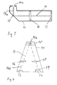
- FIG. 1 shows in the embodiment of a lancing system 1 with open device housing.
- a carrier tape 2 is arranged, which carries lancing and test elements.
- each have a channel 4 to body fluid to a test element 5 with detection reagents to transport for the photometric determination of an analyte concentration.
- the carrier tape 2 is wound up with unused lancing and test elements to a roller 6 and is guided from there to the holder 7, which holds a lancing element 3 with the associated test element 5 in one stitch.
- the holder 7 is coupled to a lancing drive 8, which moves the holder 7 from a starting position into a puncturing position, which represents the reversal point of a puncture and return movement, and back to the starting position.
- the carrier tape 2 can be wound with used lancing and test elements by means of a winding device 9. By this winding a tape transport is effected so that unused lancing and test elements can be successively guided to the holder 7.
- FIG. 3 shows a detailed view of the holder 7 with a piercing element 3 on a portion of the carrier tape 2.
- the holder consists of two holding elements 7a, 7b, which are pivotable relative to each other and hold a puncture between a lancing element 3 with a test element 5 associated therewith clamping ,
- the two holding elements 7a, 7b can be pivoted against each other about an axis, so that a gap between them opens.
- the gap is closed again by a corresponding movement of the two holding elements 7a, 7b.
- the closing movement is effected by the restoring force of a spring 10.
- the holder 7 is located in his in FIG. 3 shown at the outside of a housing 11, in which a photosensitive sensor 13 is arranged for examining a recorded from a test element 5 body fluid sample.
- a section through the housing 11 is in FIG. 5 shown.
- the housing 11 has a window 11 a through which light passes from the test element 5 to the sensor 13.
- This window 11 a is preferably designed as an opening in the housing 11. However, it is also possible to form the window 11a as a transparent housing section.
- the voltage applied to the housing 11 retaining element 7b also has a window 20 that is in FIG. 4 is shown.
- the window 20 is preferably a recess and can advantageously be formed larger than the fender 11 a, with which it is aligned in the initial position of the holder 7.
- the light-tight housing 11 shields stray light so that measurements with a good signal-to-noise ratio can be made therein.
- the housing 11 has on its outside guides 12a, 12b, in the illustrated embodiment, grooves or dovetail guides, which guide the holder 7 in a stitch movement. In this way, on the one hand a rectilinear and therefore painless stitch movement is effected, on the other hand advantageously the position of the test element 5 in the starting position of the holder 7 with respect to the housing 11 and thus in relation to the sensor 13 disposed therein very precisely predetermined.
- FIG. 6 schematically illustrated light source 17 for illuminating the test element 5, arranged for example an LED.
- Light emitted by the light source 17 is directed to the sensor 13 via optical elements, such as a lens 18, an aperture 19 and the mirror 15, and from there to the sensor 13 on a V-shaped beam path, as shown in FIG FIG. 6 is indicated.
- the beam path 14 extends in the housing 11 angled.
- An initial section 14a of the beam path starting from the test element 5 to be examined extends transversely to the stitching direction, preferably perpendicular to the stitching direction, in which the holder 7 is moved during a stitch.
- An end portion 14 b of the beam path 14 extends along the stitching direction and preferably includes an acute angle with this.
Abstract
Description
Die Erfindung betrifft ein Stechsystem mit den im Oberbegriff des Anspruch 1 angegebenen Merkmalen. Zu einem derartigen System gehört neben Stech- und Testelementen ein Handgerät mit einem Halter, der bei einem Stich ein Stechelement und ein ihm zugeordnetes Testelement hält, einem Stechantrieb, der bei einem Stich den Halter aus einer Ausgangsposition in eine Einstichposition und zurück in die Ausgangsposition bewegt, einem lichtempfindlichen Sensor zur Untersuchung einer von einem Testelement aufgenommenen Körperflüssigkeitsprobe und einer Lichtquelle zum Beleuchten des TestelementsThe invention relates to a lancing system with the features specified in the preamble of
Derartige Stechsysteme werden beispielsweise von Diabetikern benötigt, die mehrmals täglich ihren Blutzuckerspiegel überprüfen müssen und dafür eine Körperflüssigkeitsprobe, in der Regel Blut oder interstitielle Flüssigkeit benötigen, die aus einer mit einem Stechsystem erzeugten Stichwunde gewonnen wird.Such lancing systems are required, for example, by diabetics who have to check their blood sugar levels several times a day and need a body fluid sample, usually blood or interstitial fluid, which is obtained from a puncture wound produced by a lancing system.
Einen besonders hohen Benutzerkomfort bieten Stechsysteme, bei denen zum Erzeugen einer Stichwunde und dem Aufnehmen einer Probe von einer erzeugten Stichwunde dasselbe Gerät verwendet werden kann. Durch eine automatische Probenaufnahme wird einem Benutzer die Untersuchung einer Körperflüssigkeitsprobe erleichtert, was insbesondere für Personen mit einer durch Alter oder Krankheit eingeschränkten manuellen Beweglichkeit ein wichtiger Vorteil ist. Zudem besteht bei einer automatischen Probenaufnahme eine geringere Gefahr einer Probenkontamination, die zu einer Verfälschung von Messergebnissen führen könnte.A particularly high level of user comfort is provided by lancing systems in which the same device can be used to create a puncture wound and to pick up a sample from a puncture wound produced. Automated sample collection makes it easier for a user to study a sample of body fluid, which is an important benefit, especially for those with manual agility limited by age or disease. In addition, there is less risk of sample contamination in an automatic sample recording, which could lead to a falsification of measurement results.
Bei Stechsystemen der eingangs genannten Art, die eine Körperflüssigkeitsprobe mit optischen Mitteln untersuchen, beispielsweise eine photometrische Konzentrationsbestimmung vornehmen, muss Licht mit möglichst geringen Signalverlust und möglichst großem Signalrauschverhältnis von einem Testelement zu einem lichtempfindlichen Sensor geführt werden.In lancing systems of the type mentioned, which examine a body fluid sample by optical means, for example, make a photometric concentration determination, light must be performed with the lowest possible signal loss and the largest possible signal to noise ratio of a test element to a photosensitive sensor.
Aufgabe der vorliegenden Erfindung ist es, einen Weg aufzuzeigen, wie dies bei einem Stechsystem der eingangs genannten Art kostengünstig erreicht werden kann.Object of the present invention is to show a way, as can be achieved inexpensively in a lancing system of the type mentioned.
Diese Aufgabe wird durch ein Stechsystem mit den im Anspruch 1 angegebenen Merkmalen gelöst. Vorteilhafte Weiterbildungen der Erfindung sind Gegenstand von Unteransprüchen.This object is achieved by a lancing system with the features specified in
Bei einem erfindungsgemäßen Stechsystem ist der lichtempfindliche Sensor in einem Gehäuse angeordnet, an dessen Außenseite der Halter in seiner Ausgangsposition anliegt. Durch die erfindungsgemäße Maßnahme kann mit einfachen Mitteln eine präzise Positionierung des Testelements in Bezug auf den Sensor erreicht werden, so dass Messungen mit vorteilhaft geringen Probenvolumina und einer entsprechend kleinen auszuwertenden Fläche des Testelements durchgeführt werden können. Insbesondere kann durch das Gehäuse Störlicht abgeschirmt werden, so dass Messlicht von dem Testelement zu dem Sensor mit geringen Signalverlusten und einem guten Signalrauschverhältnis übertragen werden kann.In a lancing system according to the invention, the photosensitive sensor is arranged in a housing on the outside of which the holder rests in its starting position. As a result of the measure according to the invention, a precise positioning of the test element with respect to the sensor can be achieved with simple means, so that measurements can be carried out with advantageously small sample volumes and a correspondingly small area of the test element to be evaluated. In particular, the housing can be used to shield stray light, so that measuring light can be transmitted from the test element to the sensor with low signal losses and a good signal-to-noise ratio.
Bei einem erfindungsgemäßen Stechsystem können Stechelemente verwendet werden, die integral mit Testelementen ausgebildet sind, wie dies beispielsweise aus der
Eine vorteilhafte Weiterbildung der Erfindung sieht vor, dass das Gehäuse an seiner Außenseite eine Führung aufweist, die bei einer Stichbewegung den Halter führt. Auf diese Weise lässt sich erreichen, dass der Halter in seiner Ausgangsposition stets reproduzierbar und mit hoher Genauigkeit eine vorgegebene Position in Bezug auf das Gehäuse und damit in Bezug auf den in dem Gehäuse angeordneten Sensor einnimmt. Dies hat den Vorteil, dass ein von dem Halter gehaltenes Testelement ebenfalls mit hoher Präzision eine definierte Ausgangsposition für eine Messung einnimmt und deshalb der von dem Sensor erfasste Bereich auf eine vorteilhaft kleine Fläche begrenzt werden kann. Dies ist insbesondere für Messungen mit kleinen Probenvolumina ein wichtiger Vorteil, da kleine Probenvolumina nur kleine Flächen benetzen können und das Signalrauschverhältnis im allgemeinen um so besser ist, je besser der von dem Sensor erfasste Bereich mit der für die Messung relevanten Fläche des Testelements übereinstimmt. Bevorzugt ist die Führung eine Linearführung, beispielsweise eine Schwalbenschwanzführung oder eine Schienenführung.An advantageous development of the invention provides that the housing has on its outer side a guide which guides the holder in a stitch movement. In this way it can be achieved that the holder in its starting position always reproducible and with high accuracy assumes a predetermined position with respect to the housing and thus with respect to the sensor disposed in the housing. This has the advantage that a test element held by the holder likewise assumes a defined starting position for a measurement with high precision, and therefore the area covered by the sensor can be limited to an advantageously small area. This is an important advantage, in particular for measurements with small sample volumes, since small sample volumes can only wet small areas and the signal-to-noise ratio is generally better the better the area covered by the sensor matches the area of the test element relevant to the measurement. The guide is preferably a linear guide, for example a dovetail guide or a rail guide.
Eine weitere vorteilhafte Weiterbildung der Erfindung sieht vor, dass auch die Lichtquelle zum Beleuchten des Testelements in dem Gehäuse angeordnet ist. Auf diese Weise lässt sich eine störende Beeinflussung der Messung durch Umgebungslicht weitestgehend ausschließen, da im Wesentlichen der gesamte Strahlengang von der Lichtquelle zu dem Testelement und von dem Testelement zu dem Sensor abgeschirmt in dem Gehäuse verlaufen kann. Prinzipiell ist es aber auch möglich, die Lichtquelle außerhalb des Gehäuses anzuordnen und ein Testelement beispielsweise in Transmissionen zu untersuchen.A further advantageous development of the invention provides that the light source for illuminating the test element is also arranged in the housing. In this way, a disturbing influence of the measurement by ambient light can be largely excluded, since substantially the entire beam path can extend from the light source to the test element and from the test element to the sensor shielded in the housing. In principle, it is also possible to arrange the light source outside the housing and to examine a test element, for example in transmissions.
Bevorzugt ist in dem Gehäuse mindestens ein optisches Element, beispielsweise eine oder mehrere Linsen und/ oder einer oder mehrere Spiegel. Auf diese Weise kann in dem Gehäuse ein optischer Strahlengang für eine präzise Messung vorgegeben werden, der den im Gerät zur Verfügung stehenden Bauraum optimal ausnutzt.At least one optical element, for example one or more lenses and / or one or more mirrors, is preferred in the housing. In this way, an optical beam path for a precise measurement can be specified in the housing, which optimally utilizes the space available in the device space.
Bevorzugt ist das den Sensor enthaltende Gehäuse ortsfest im Inneren des Geräts angeordnet. Prinzipiell ist es aber auch möglich, den Sensor in einem mehrteiligen Gehäuse anzuordnen, das einen Gehäuseteil aufweist, der sich bei einem Stich zusammen mit dem Halter bewegt.Preferably, the housing containing the sensor is arranged stationarily in the interior of the device. In principle, it is also possible to arrange the sensor in a multi-part housing, which has a housing part which moves in a stitch together with the holder.
Weitere Einzelheiten und Vorteile der Erfindung werden an einem Ausführungsbeispiel unter Bezugnahem auf die beigefügten Zeichnungen erläutert. Es zeigen:
- Figur 1:
- eine schematische Darstellung eines erfindungsgemäßen Stechsys- tems mit geöffnetem Gerätegehäuse;
- Figur 2:
- eine schematische Darstellung eines Stechelements mit einem Test- element;
- Figur 3:
- den Halter des dargestellten Stechsystems mit einem Stechelement und einem Gehäuse, in dem ein Sensor angeordnet ist;
- Figur 4:
- eine Explosionsvorstellung zu
Figur 3 - Figur 5:
- eine Schnittansicht des den Sensor enthaltenden Gehäuses
- Figur 6:
- eine weitere Schnittansicht des den Sensor enthaltenden Gehäuses.
- FIG. 1:
- a schematic representation of a lancing system according to the invention with open device housing;
- FIG. 2:
- a schematic representation of a lancing element with a test element;
- FIG. 3:
- the holder of the illustrated lancing system with a lancing element and a housing in which a sensor is arranged;
- FIG. 4:
- an explosion to
FIG. 3 ; - FIG. 5:
- a sectional view of the housing containing the sensor
- FIG. 6:
- a further sectional view of the housing containing the sensor.
Das Trägerband 2 ist mit unbenutzten Stech- und Testelementen zu einer Rolle 6 aufgewickelt und wird von dort zu dem Halter 7, der bei einem Stich ein Stechelement 3 mit dem zugeordneten Testelement 5 hält, geführt. Der Halter 7 ist mit einem Stechantrieb 8 gekoppelt, der bei einem Stich den Halter 7 aus einer Ausgangsposition in eine Einstichposition, die den Umkehrpunkt einer Stich- und Rückführbewegung darstellt, und wieder zurück in die Ausgangsposition bewegt.The
Das Trägerband 2 kann mit benutzten Stech- und Testelementen mittels einer Wickeleinrichtung 9 aufgewickelt werden. Durch diesen Aufwickelvorgang wird ein Bandtransport bewirkt, so dass unbenutzte Stech- und Testelemente nacheinander zu dem Halter 7 geführt werden können.The
Der Halter 7 liegt in seiner in
Das lichtdichte Gehäuse 11 schirmt Störlicht ab, so dass darin Messungen mit einem guten Signalrauschverhältnis vorgenommen werden können. Das Gehäuse 11 weist an seiner Außenseite Führungen 12a, 12b, bei dem dargestellten Ausführungsbeispiel Nuten bzw. Schwalbenschwanzführungen, auf, die bei einer Stichbewegung den Halter 7 führen. Auf diese Weise wird einerseits eine geradlinige und deshalb schmerzarme Stichbewegung bewirkt, andererseits wird vorteilhaft die Position des Testelements 5 in der Ausgangsposition des Halters 7 in Bezug auf das Gehäuse 11 und damit in Bezug auf den darin angeordneten Sensor 13 sehr präzise vorgegeben.The light-
Der in dem Gehäuse 11 angeordnete Sensor 13 und ein dazugehörender Strahlengang 14 mit optischen Elementen 15, 16, die schematisch in
In dem sich in Stichrichtung V-förmig verjüngenden Gehäuse ist auch eine in
Der Strahlengang 14 verläuft in dem Gehäuse 11 gewinkelt. Ein von dem zu untersuchenden Testelement 5 ausgehender Anfangsabschnitt 14a des Strahlengangs verläuft quer zur Stichrichtung, bevorzugt senkrecht zu der Stichrichtung, in welcher der Halter 7 bei einem Stich bewegt wird. Ein Endabschnitt 14 b des Strahlengangs 14 verläuft entlang der Stichrichtung und schließt mit dieser bevorzugt einen spitzen Winkel ein.The
- 11
- Stechsystempiercing system
- 22
- Trägerbandcarrier tape
- 33
- Stechelementpiercing member
- 44
- Kanalchannel
- 55
- Testelementtest element
- 66
- Rollerole
- 77
- Halterholder
- 7a7a
- Halteelementretaining element
- 7b7b
- Halteelementretaining element
- 88th
- Stechantrieblancing drive
- 99
- Wickeleinrichtungwinding device
- 1010
- Federfeather
- 1111
- Gehäusecasing
- 11a11a
- Fensterwindow
- 1212
- 12a12a
- Führungenguides
- 12b12b
- Führungenguides
- 1313
- Sensorsensor
- 1414
- Strahlengangbeam path
- 14a14a
- Anfangsabschnittinitial section
- 14b14b
- Endabschnittend
- 1515
- Spiegelmirror
- 1616
- Linselens
- 1717
- Lichtquellelight source
- 1818
- Linselens
- 1919
- Blendecover
- 2020
- Fensterwindow
Claims (15)
Testelementen (5),
Stechelementen (3), denen jeweils ein Testelement (5) zugeordnet ist, und einem Handgerät, das einen Halter (7), der bei einem Stich ein Stechelement (3) und ein ihm zugeordnetes Testelement (5) hält, einen Stechantrieb (8), der bei einem Stich den Halter (7) aus einer Ausgangsposition in eine Einstichposition und zurück in die Ausgangsposition bewegt, einen lichtempfindlichen Sensor (13) zur Untersuchung einer von einem Testelement (5) aufgenommenen Körperflüssigkeitsprobe und eine Lichtquelle (17) zum Beleuchten des Testelements (5) aufweist,
dadurch gekennzeichnet, dass
der Sensor (13) in einem Gehäuse (11) angeordnet ist, an dessen Außenseite der Halter (7) in seiner Ausgangsposition anliegt.Lancing system with
Test elements (5),
Lancing elements (3), each of which has a test element (5) associated therewith, and a hand-held device which holds a holder (7) which holds a lancing element (3) and a test element (5) associated therewith in a stitch, a puncturing drive (8) moving the holder (7) from an initial position to a puncturing position and back to the starting position at one stitch, a photosensitive sensor (13) for examining a body fluid sample picked up by a test element (5) and a light source (17) for illuminating the test element (5),
characterized in that
the sensor (13) is arranged in a housing (11) on the outside of which the holder (7) rests in its initial position.
Priority Applications (3)
| Application Number | Priority Date | Filing Date | Title |
|---|---|---|---|
| EP09002121.3A EP2218392B1 (en) | 2009-02-16 | 2009-02-16 | Piercing system |
| PCT/EP2010/000564 WO2010091794A1 (en) | 2009-02-16 | 2010-01-30 | Piercing system |
| US13/210,626 US8348857B2 (en) | 2009-02-16 | 2011-08-16 | Lancing system |
Applications Claiming Priority (1)
| Application Number | Priority Date | Filing Date | Title |
|---|---|---|---|
| EP09002121.3A EP2218392B1 (en) | 2009-02-16 | 2009-02-16 | Piercing system |
Publications (2)
| Publication Number | Publication Date |
|---|---|
| EP2218392A1 true EP2218392A1 (en) | 2010-08-18 |
| EP2218392B1 EP2218392B1 (en) | 2016-11-16 |
Family
ID=40652692
Family Applications (1)
| Application Number | Title | Priority Date | Filing Date |
|---|---|---|---|
| EP09002121.3A Not-in-force EP2218392B1 (en) | 2009-02-16 | 2009-02-16 | Piercing system |
Country Status (3)
| Country | Link |
|---|---|
| US (1) | US8348857B2 (en) |
| EP (1) | EP2218392B1 (en) |
| WO (1) | WO2010091794A1 (en) |
Cited By (2)
| Publication number | Priority date | Publication date | Assignee | Title |
|---|---|---|---|---|
| WO2013070488A1 (en) * | 2011-11-08 | 2013-05-16 | Facet Technologies, Llc | Lancing device with cam-actuated drive and separate guidance |
| CN114052682A (en) * | 2021-12-14 | 2022-02-18 | 重庆科技学院 | Physiological parameter monitoring system based on raspberry group |
Families Citing this family (2)
| Publication number | Priority date | Publication date | Assignee | Title |
|---|---|---|---|---|
| EP2520225B1 (en) | 2011-05-06 | 2014-05-21 | Roche Diagnostics GmbH | Lancet |
| CN107246990A (en) * | 2016-03-28 | 2017-10-13 | 上海微创医疗器械(集团)有限公司 | Foley's tube test system and method for testing |
Citations (11)
| Publication number | Priority date | Publication date | Assignee | Title |
|---|---|---|---|---|
| EP0254203A2 (en) * | 1986-07-22 | 1988-01-27 | Personal Diagnostics, Inc. | Optical analyzer |
| EP0931507A1 (en) * | 1998-01-22 | 1999-07-28 | Terumo Kabushiki Kaisha | Body-fluid inspection device |
| WO2000040150A1 (en) * | 1999-01-04 | 2000-07-13 | Terumo Kabushiki Kaisha | Assembly having lancet and means for collecting and detecting body fluid |
| WO2004041082A1 (en) * | 2002-11-01 | 2004-05-21 | Pelikan Technologies, Inc. | Method and apparatus for body fluid sampling |
| US20040132167A1 (en) * | 2003-01-06 | 2004-07-08 | Peter Rule | Cartridge lance |
| WO2005107596A2 (en) | 2004-04-30 | 2005-11-17 | Roche Diagnostics Gmbh | Lancets for bodily fluid sampling supplied on a tape |
| EP1598011A2 (en) * | 2002-05-09 | 2005-11-23 | Lifescan, Inc. | Physiological sample collection devices and methods of using the same |
| EP1360935B1 (en) | 2002-05-09 | 2006-12-06 | Lifescan, Inc. | Strip containing a series of fluid sampling and testing devices and method of making, packaging and using it |
| WO2007041244A2 (en) * | 2005-09-30 | 2007-04-12 | Intuity Medical, Inc. | Multi-site body fluid sampling and analysis cartridge |
| WO2008131920A2 (en) * | 2007-04-30 | 2008-11-06 | Roche Diagnostics Gmbh | Instrument and system for producing a sample of a body liquid and for analysis thereof |
| EP2030566A1 (en) * | 2007-08-31 | 2009-03-04 | Roche Diagnostics GmbH | Analysis system for determining an analyte in a body fluid, magazine for an analysis system, integrated sample acquisition and analyzing element, and method for analyzing a body fluid |
-
2009
- 2009-02-16 EP EP09002121.3A patent/EP2218392B1/en not_active Not-in-force
-
2010
- 2010-01-30 WO PCT/EP2010/000564 patent/WO2010091794A1/en active Application Filing
-
2011
- 2011-08-16 US US13/210,626 patent/US8348857B2/en active Active
Patent Citations (11)
| Publication number | Priority date | Publication date | Assignee | Title |
|---|---|---|---|---|
| EP0254203A2 (en) * | 1986-07-22 | 1988-01-27 | Personal Diagnostics, Inc. | Optical analyzer |
| EP0931507A1 (en) * | 1998-01-22 | 1999-07-28 | Terumo Kabushiki Kaisha | Body-fluid inspection device |
| WO2000040150A1 (en) * | 1999-01-04 | 2000-07-13 | Terumo Kabushiki Kaisha | Assembly having lancet and means for collecting and detecting body fluid |
| EP1598011A2 (en) * | 2002-05-09 | 2005-11-23 | Lifescan, Inc. | Physiological sample collection devices and methods of using the same |
| EP1360935B1 (en) | 2002-05-09 | 2006-12-06 | Lifescan, Inc. | Strip containing a series of fluid sampling and testing devices and method of making, packaging and using it |
| WO2004041082A1 (en) * | 2002-11-01 | 2004-05-21 | Pelikan Technologies, Inc. | Method and apparatus for body fluid sampling |
| US20040132167A1 (en) * | 2003-01-06 | 2004-07-08 | Peter Rule | Cartridge lance |
| WO2005107596A2 (en) | 2004-04-30 | 2005-11-17 | Roche Diagnostics Gmbh | Lancets for bodily fluid sampling supplied on a tape |
| WO2007041244A2 (en) * | 2005-09-30 | 2007-04-12 | Intuity Medical, Inc. | Multi-site body fluid sampling and analysis cartridge |
| WO2008131920A2 (en) * | 2007-04-30 | 2008-11-06 | Roche Diagnostics Gmbh | Instrument and system for producing a sample of a body liquid and for analysis thereof |
| EP2030566A1 (en) * | 2007-08-31 | 2009-03-04 | Roche Diagnostics GmbH | Analysis system for determining an analyte in a body fluid, magazine for an analysis system, integrated sample acquisition and analyzing element, and method for analyzing a body fluid |
Cited By (3)
| Publication number | Priority date | Publication date | Assignee | Title |
|---|---|---|---|---|
| WO2013070488A1 (en) * | 2011-11-08 | 2013-05-16 | Facet Technologies, Llc | Lancing device with cam-actuated drive and separate guidance |
| CN114052682A (en) * | 2021-12-14 | 2022-02-18 | 重庆科技学院 | Physiological parameter monitoring system based on raspberry group |
| CN114052682B (en) * | 2021-12-14 | 2023-10-24 | 重庆科技学院 | Physiological parameter monitoring system based on raspberry group |
Also Published As
| Publication number | Publication date |
|---|---|
| US20120041340A1 (en) | 2012-02-16 |
| EP2218392B1 (en) | 2016-11-16 |
| WO2010091794A1 (en) | 2010-08-19 |
| US8348857B2 (en) | 2013-01-08 |
Similar Documents
| Publication | Publication Date | Title |
|---|---|---|
| EP1635699B1 (en) | Integrated test element for a one-time drawing and analyzing of a sample to be analyzed | |
| EP1240503B1 (en) | Test strip analysis system, medical test strip, and method of analysing a sample by the help of a test strip analysis system | |
| EP1878379B1 (en) | Test tape system, in particular for blood sugar analysis | |
| EP1743162B2 (en) | Device for the analysis or absorption measurement of a small quantity of a liquid medium by means of light | |
| EP1785730A1 (en) | System and method for examining a liquid sample | |
| DE19948195A1 (en) | Method and device for the optical measurement of very small liquid samples | |
| EP1736774A1 (en) | Analytic system for the analysis of a sample on an analytic test element | |
| DE19844500A1 (en) | Process for the photometric evaluation of test elements | |
| DE10311452A1 (en) | Reagent-free system for determination of the concentration of an analysis compound in living tissue, comprises a Raman scattering system for detection and analysis of selected wavelengths of light scattered from the tissue | |
| DE10332488A1 (en) | Analyzer and analysis method for body fluids | |
| EP2218392B1 (en) | Piercing system | |
| EP1929937A1 (en) | Device and method for investigating body fluids | |
| EP1027593A1 (en) | Process and device for carrying out fluorescence immunoassays | |
| WO2009030340A1 (en) | Analysis device for determining an analyte in a body fluid, magazine for an analysis device and method for creating a wound for examining a leaking body fluid | |
| DE102013020703B4 (en) | Raman probe device and method using this device | |
| EP1911394B1 (en) | Lancet with capillar channel | |
| EP2427101B1 (en) | Test unit for use in an test device and test system | |
| DE19519051A1 (en) | Polarimetric in=vivo determination of blood sugar concn. | |
| EP2442708B1 (en) | Piercing system | |
| DE19734618A1 (en) | Analyser for in-vivo determination of analytes in body of patient | |
| DE202013012102U1 (en) | Photoacoustic device | |
| WO2013053381A1 (en) | Method and device for determining a substance concentration by means of fluorescence spectroscopy | |
| DE102014226381A1 (en) | Holding device, system and method for optically reading a test strip | |
| DE102021210443A1 (en) | Submersible probe with variable path length | |
| DE102019133365A1 (en) | Arrangement for operating a biosensor and arrangement for determining the glucose content in the blood |
Legal Events
| Date | Code | Title | Description |
|---|---|---|---|
| PUAI | Public reference made under article 153(3) epc to a published international application that has entered the european phase |
Free format text: ORIGINAL CODE: 0009012 |
|
| AK | Designated contracting states |
Kind code of ref document: A1 Designated state(s): AT BE BG CH CY CZ DE DK EE ES FI FR GB GR HR HU IE IS IT LI LT LU LV MC MK MT NL NO PL PT RO SE SI SK TR |
|
| AX | Request for extension of the european patent |
Extension state: AL BA RS |
|
| 17P | Request for examination filed |
Effective date: 20101120 |
|
| 17Q | First examination report despatched |
Effective date: 20100112 |
|
| R17C | First examination report despatched (corrected) |
Effective date: 20110112 |
|
| AKX | Designation fees paid |
Designated state(s): AT BE BG CH CY CZ DE DK EE ES FI FR GB GR HR HU IE IS IT LI LT LU LV MC MK MT NL NO PL PT RO SE SI SK TR |
|
| REG | Reference to a national code |
Ref country code: DE Ref legal event code: R079 Ref document number: 502009013369 Country of ref document: DE Free format text: PREVIOUS MAIN CLASS: A61B0005000000 Ipc: A61B0005145500 |
|
| GRAP | Despatch of communication of intention to grant a patent |
Free format text: ORIGINAL CODE: EPIDOSNIGR1 |
|
| INTG | Intention to grant announced |
Effective date: 20160404 |
|
| RIC1 | Information provided on ipc code assigned before grant |
Ipc: A61B 5/1455 20060101AFI20160318BHEP |
|
| GRAS | Grant fee paid |
Free format text: ORIGINAL CODE: EPIDOSNIGR3 |
|
| GRAJ | Information related to disapproval of communication of intention to grant by the applicant or resumption of examination proceedings by the epo deleted |
Free format text: ORIGINAL CODE: EPIDOSDIGR1 |
|
| GRAL | Information related to payment of fee for publishing/printing deleted |
Free format text: ORIGINAL CODE: EPIDOSDIGR3 |
|
| RAP1 | Party data changed (applicant data changed or rights of an application transferred) |
Owner name: F.HOFFMANN-LA ROCHE AG Owner name: ROCHE DIABETES CARE GMBH |
|
| INTC | Intention to grant announced (deleted) | ||
| GRAP | Despatch of communication of intention to grant a patent |
Free format text: ORIGINAL CODE: EPIDOSNIGR1 |
|
| INTG | Intention to grant announced |
Effective date: 20160907 |
|
| RAP1 | Party data changed (applicant data changed or rights of an application transferred) |
Owner name: F. HOFFMANN-LA ROCHE AG Owner name: ROCHE DIABETES CARE GMBH |
|
| GRAA | (expected) grant |
Free format text: ORIGINAL CODE: 0009210 |
|
| AK | Designated contracting states |
Kind code of ref document: B1 Designated state(s): AT BE BG CH CY CZ DE DK EE ES FI FR GB GR HR HU IE IS IT LI LT LU LV MC MK MT NL NO PL PT RO SE SI SK TR |
|
| REG | Reference to a national code |
Ref country code: GB Ref legal event code: FG4D Free format text: NOT ENGLISH |
|
| REG | Reference to a national code |
Ref country code: CH Ref legal event code: EP |
|
| REG | Reference to a national code |
Ref country code: IE Ref legal event code: FG4D Free format text: LANGUAGE OF EP DOCUMENT: GERMAN |
|
| REG | Reference to a national code |
Ref country code: AT Ref legal event code: REF Ref document number: 845106 Country of ref document: AT Kind code of ref document: T Effective date: 20161215 |
|
| REG | Reference to a national code |
Ref country code: DE Ref legal event code: R096 Ref document number: 502009013369 Country of ref document: DE |
|
| REG | Reference to a national code |
Ref country code: DE Ref legal event code: R096 Ref document number: 502009013369 Country of ref document: DE |
|
| PG25 | Lapsed in a contracting state [announced via postgrant information from national office to epo] |
Ref country code: LV Free format text: LAPSE BECAUSE OF FAILURE TO SUBMIT A TRANSLATION OF THE DESCRIPTION OR TO PAY THE FEE WITHIN THE PRESCRIBED TIME-LIMIT Effective date: 20161116 |
|
| REG | Reference to a national code |
Ref country code: NL Ref legal event code: MP Effective date: 20161116 |
|
| REG | Reference to a national code |
Ref country code: LT Ref legal event code: MG4D |
|
| PG25 | Lapsed in a contracting state [announced via postgrant information from national office to epo] |
Ref country code: NO Free format text: LAPSE BECAUSE OF FAILURE TO SUBMIT A TRANSLATION OF THE DESCRIPTION OR TO PAY THE FEE WITHIN THE PRESCRIBED TIME-LIMIT Effective date: 20170216 Ref country code: LT Free format text: LAPSE BECAUSE OF FAILURE TO SUBMIT A TRANSLATION OF THE DESCRIPTION OR TO PAY THE FEE WITHIN THE PRESCRIBED TIME-LIMIT Effective date: 20161116 Ref country code: NL Free format text: LAPSE BECAUSE OF FAILURE TO SUBMIT A TRANSLATION OF THE DESCRIPTION OR TO PAY THE FEE WITHIN THE PRESCRIBED TIME-LIMIT Effective date: 20161116 Ref country code: GR Free format text: LAPSE BECAUSE OF FAILURE TO SUBMIT A TRANSLATION OF THE DESCRIPTION OR TO PAY THE FEE WITHIN THE PRESCRIBED TIME-LIMIT Effective date: 20170217 Ref country code: SE Free format text: LAPSE BECAUSE OF FAILURE TO SUBMIT A TRANSLATION OF THE DESCRIPTION OR TO PAY THE FEE WITHIN THE PRESCRIBED TIME-LIMIT Effective date: 20161116 |
|
| PG25 | Lapsed in a contracting state [announced via postgrant information from national office to epo] |
Ref country code: PT Free format text: LAPSE BECAUSE OF FAILURE TO SUBMIT A TRANSLATION OF THE DESCRIPTION OR TO PAY THE FEE WITHIN THE PRESCRIBED TIME-LIMIT Effective date: 20170316 Ref country code: HR Free format text: LAPSE BECAUSE OF FAILURE TO SUBMIT A TRANSLATION OF THE DESCRIPTION OR TO PAY THE FEE WITHIN THE PRESCRIBED TIME-LIMIT Effective date: 20161116 Ref country code: BE Free format text: LAPSE BECAUSE OF NON-PAYMENT OF DUE FEES Effective date: 20170228 Ref country code: ES Free format text: LAPSE BECAUSE OF FAILURE TO SUBMIT A TRANSLATION OF THE DESCRIPTION OR TO PAY THE FEE WITHIN THE PRESCRIBED TIME-LIMIT Effective date: 20161116 Ref country code: FI Free format text: LAPSE BECAUSE OF FAILURE TO SUBMIT A TRANSLATION OF THE DESCRIPTION OR TO PAY THE FEE WITHIN THE PRESCRIBED TIME-LIMIT Effective date: 20161116 Ref country code: PL Free format text: LAPSE BECAUSE OF FAILURE TO SUBMIT A TRANSLATION OF THE DESCRIPTION OR TO PAY THE FEE WITHIN THE PRESCRIBED TIME-LIMIT Effective date: 20161116 |
|
| PG25 | Lapsed in a contracting state [announced via postgrant information from national office to epo] |
Ref country code: DK Free format text: LAPSE BECAUSE OF FAILURE TO SUBMIT A TRANSLATION OF THE DESCRIPTION OR TO PAY THE FEE WITHIN THE PRESCRIBED TIME-LIMIT Effective date: 20161116 Ref country code: SK Free format text: LAPSE BECAUSE OF FAILURE TO SUBMIT A TRANSLATION OF THE DESCRIPTION OR TO PAY THE FEE WITHIN THE PRESCRIBED TIME-LIMIT Effective date: 20161116 Ref country code: EE Free format text: LAPSE BECAUSE OF FAILURE TO SUBMIT A TRANSLATION OF THE DESCRIPTION OR TO PAY THE FEE WITHIN THE PRESCRIBED TIME-LIMIT Effective date: 20161116 Ref country code: CZ Free format text: LAPSE BECAUSE OF FAILURE TO SUBMIT A TRANSLATION OF THE DESCRIPTION OR TO PAY THE FEE WITHIN THE PRESCRIBED TIME-LIMIT Effective date: 20161116 Ref country code: RO Free format text: LAPSE BECAUSE OF FAILURE TO SUBMIT A TRANSLATION OF THE DESCRIPTION OR TO PAY THE FEE WITHIN THE PRESCRIBED TIME-LIMIT Effective date: 20161116 |
|
| REG | Reference to a national code |
Ref country code: DE Ref legal event code: R097 Ref document number: 502009013369 Country of ref document: DE |
|
| PG25 | Lapsed in a contracting state [announced via postgrant information from national office to epo] |
Ref country code: IT Free format text: LAPSE BECAUSE OF FAILURE TO SUBMIT A TRANSLATION OF THE DESCRIPTION OR TO PAY THE FEE WITHIN THE PRESCRIBED TIME-LIMIT Effective date: 20161116 Ref country code: BG Free format text: LAPSE BECAUSE OF FAILURE TO SUBMIT A TRANSLATION OF THE DESCRIPTION OR TO PAY THE FEE WITHIN THE PRESCRIBED TIME-LIMIT Effective date: 20170216 |
|
| PLBE | No opposition filed within time limit |
Free format text: ORIGINAL CODE: 0009261 |
|
| STAA | Information on the status of an ep patent application or granted ep patent |
Free format text: STATUS: NO OPPOSITION FILED WITHIN TIME LIMIT |
|
| PG25 | Lapsed in a contracting state [announced via postgrant information from national office to epo] |
Ref country code: MC Free format text: LAPSE BECAUSE OF FAILURE TO SUBMIT A TRANSLATION OF THE DESCRIPTION OR TO PAY THE FEE WITHIN THE PRESCRIBED TIME-LIMIT Effective date: 20161116 |
|
| REG | Reference to a national code |
Ref country code: CH Ref legal event code: PL |
|
| 26N | No opposition filed |
Effective date: 20170817 |
|
| GBPC | Gb: european patent ceased through non-payment of renewal fee |
Effective date: 20170216 |
|
| PG25 | Lapsed in a contracting state [announced via postgrant information from national office to epo] |
Ref country code: LI Free format text: LAPSE BECAUSE OF NON-PAYMENT OF DUE FEES Effective date: 20170228 Ref country code: CH Free format text: LAPSE BECAUSE OF NON-PAYMENT OF DUE FEES Effective date: 20170228 |
|
| REG | Reference to a national code |
Ref country code: IE Ref legal event code: MM4A |
|
| PG25 | Lapsed in a contracting state [announced via postgrant information from national office to epo] |
Ref country code: SI Free format text: LAPSE BECAUSE OF FAILURE TO SUBMIT A TRANSLATION OF THE DESCRIPTION OR TO PAY THE FEE WITHIN THE PRESCRIBED TIME-LIMIT Effective date: 20161116 |
|
| REG | Reference to a national code |
Ref country code: FR Ref legal event code: ST Effective date: 20171031 |
|
| PG25 | Lapsed in a contracting state [announced via postgrant information from national office to epo] |
Ref country code: LU Free format text: LAPSE BECAUSE OF NON-PAYMENT OF DUE FEES Effective date: 20170216 |
|
| PG25 | Lapsed in a contracting state [announced via postgrant information from national office to epo] |
Ref country code: FR Free format text: LAPSE BECAUSE OF NON-PAYMENT OF DUE FEES Effective date: 20170228 |
|
| REG | Reference to a national code |
Ref country code: BE Ref legal event code: MM Effective date: 20170228 |
|
| PG25 | Lapsed in a contracting state [announced via postgrant information from national office to epo] |
Ref country code: IE Free format text: LAPSE BECAUSE OF NON-PAYMENT OF DUE FEES Effective date: 20170216 Ref country code: GB Free format text: LAPSE BECAUSE OF NON-PAYMENT OF DUE FEES Effective date: 20170216 |
|
| REG | Reference to a national code |
Ref country code: AT Ref legal event code: MM01 Ref document number: 845106 Country of ref document: AT Kind code of ref document: T Effective date: 20170216 |
|
| PG25 | Lapsed in a contracting state [announced via postgrant information from national office to epo] |
Ref country code: AT Free format text: LAPSE BECAUSE OF NON-PAYMENT OF DUE FEES Effective date: 20170216 |
|
| PG25 | Lapsed in a contracting state [announced via postgrant information from national office to epo] |
Ref country code: MT Free format text: LAPSE BECAUSE OF FAILURE TO SUBMIT A TRANSLATION OF THE DESCRIPTION OR TO PAY THE FEE WITHIN THE PRESCRIBED TIME-LIMIT Effective date: 20161116 |
|
| PG25 | Lapsed in a contracting state [announced via postgrant information from national office to epo] |
Ref country code: HU Free format text: LAPSE BECAUSE OF FAILURE TO SUBMIT A TRANSLATION OF THE DESCRIPTION OR TO PAY THE FEE WITHIN THE PRESCRIBED TIME-LIMIT; INVALID AB INITIO Effective date: 20090216 |
|
| PG25 | Lapsed in a contracting state [announced via postgrant information from national office to epo] |
Ref country code: CY Free format text: LAPSE BECAUSE OF NON-PAYMENT OF DUE FEES Effective date: 20161116 |
|
| PG25 | Lapsed in a contracting state [announced via postgrant information from national office to epo] |
Ref country code: MK Free format text: LAPSE BECAUSE OF FAILURE TO SUBMIT A TRANSLATION OF THE DESCRIPTION OR TO PAY THE FEE WITHIN THE PRESCRIBED TIME-LIMIT Effective date: 20161116 |
|
| PG25 | Lapsed in a contracting state [announced via postgrant information from national office to epo] |
Ref country code: TR Free format text: LAPSE BECAUSE OF FAILURE TO SUBMIT A TRANSLATION OF THE DESCRIPTION OR TO PAY THE FEE WITHIN THE PRESCRIBED TIME-LIMIT Effective date: 20161116 |
|
| PG25 | Lapsed in a contracting state [announced via postgrant information from national office to epo] |
Ref country code: IS Free format text: LAPSE BECAUSE OF FAILURE TO SUBMIT A TRANSLATION OF THE DESCRIPTION OR TO PAY THE FEE WITHIN THE PRESCRIBED TIME-LIMIT Effective date: 20170316 |
|
| PGFP | Annual fee paid to national office [announced via postgrant information from national office to epo] |
Ref country code: DE Payment date: 20210113 Year of fee payment: 13 |
|
| REG | Reference to a national code |
Ref country code: DE Ref legal event code: R119 Ref document number: 502009013369 Country of ref document: DE |
|
| PG25 | Lapsed in a contracting state [announced via postgrant information from national office to epo] |
Ref country code: DE Free format text: LAPSE BECAUSE OF NON-PAYMENT OF DUE FEES Effective date: 20220901 |