EP2210841A2 - Conveyor comprising aligning cams - Google Patents
Conveyor comprising aligning cams Download PDFInfo
- Publication number
- EP2210841A2 EP2210841A2 EP09405167A EP09405167A EP2210841A2 EP 2210841 A2 EP2210841 A2 EP 2210841A2 EP 09405167 A EP09405167 A EP 09405167A EP 09405167 A EP09405167 A EP 09405167A EP 2210841 A2 EP2210841 A2 EP 2210841A2
- Authority
- EP
- European Patent Office
- Prior art keywords
- products
- conveyor
- leading
- distance
- conveying
- Prior art date
- Legal status (The legal status is an assumption and is not a legal conclusion. Google has not performed a legal analysis and makes no representation as to the accuracy of the status listed.)
- Withdrawn
Links
Images


Classifications
-
- B—PERFORMING OPERATIONS; TRANSPORTING
- B65—CONVEYING; PACKING; STORING; HANDLING THIN OR FILAMENTARY MATERIAL
- B65H—HANDLING THIN OR FILAMENTARY MATERIAL, e.g. SHEETS, WEBS, CABLES
- B65H33/00—Forming counted batches in delivery pile or stream of articles
- B65H33/16—Forming counted batches in delivery pile or stream of articles by depositing articles in batches on moving supports
- B65H33/18—Forming counted batches in delivery pile or stream of articles by depositing articles in batches on moving supports with separators between adjacent batches
-
- B—PERFORMING OPERATIONS; TRANSPORTING
- B65—CONVEYING; PACKING; STORING; HANDLING THIN OR FILAMENTARY MATERIAL
- B65G—TRANSPORT OR STORAGE DEVICES, e.g. CONVEYORS FOR LOADING OR TIPPING, SHOP CONVEYOR SYSTEMS OR PNEUMATIC TUBE CONVEYORS
- B65G17/00—Conveyors having an endless traction element, e.g. a chain, transmitting movement to a continuous or substantially-continuous load-carrying surface or to a series of individual load-carriers; Endless-chain conveyors in which the chains form the load-carrying surface
- B65G17/26—Conveyors having an endless traction element, e.g. a chain, transmitting movement to a continuous or substantially-continuous load-carrying surface or to a series of individual load-carriers; Endless-chain conveyors in which the chains form the load-carrying surface comprising a series of co-operating units, e.g. interconnected by pivots
-
- B—PERFORMING OPERATIONS; TRANSPORTING
- B65—CONVEYING; PACKING; STORING; HANDLING THIN OR FILAMENTARY MATERIAL
- B65G—TRANSPORT OR STORAGE DEVICES, e.g. CONVEYORS FOR LOADING OR TIPPING, SHOP CONVEYOR SYSTEMS OR PNEUMATIC TUBE CONVEYORS
- B65G23/00—Driving gear for endless conveyors; Belt- or chain-tensioning arrangements
- B65G23/24—Gearing between driving motor and belt- or chain-engaging elements
- B65G23/30—Variable-speed gearing
-
- B—PERFORMING OPERATIONS; TRANSPORTING
- B65—CONVEYING; PACKING; STORING; HANDLING THIN OR FILAMENTARY MATERIAL
- B65G—TRANSPORT OR STORAGE DEVICES, e.g. CONVEYORS FOR LOADING OR TIPPING, SHOP CONVEYOR SYSTEMS OR PNEUMATIC TUBE CONVEYORS
- B65G47/00—Article or material-handling devices associated with conveyors; Methods employing such devices
- B65G47/74—Feeding, transfer, or discharging devices of particular kinds or types
- B65G47/84—Star-shaped wheels or devices having endless travelling belts or chains, the wheels or devices being equipped with article-engaging elements
- B65G47/841—Devices having endless travelling belts or chains equipped with article-engaging elements
-
- B—PERFORMING OPERATIONS; TRANSPORTING
- B65—CONVEYING; PACKING; STORING; HANDLING THIN OR FILAMENTARY MATERIAL
- B65H—HANDLING THIN OR FILAMENTARY MATERIAL, e.g. SHEETS, WEBS, CABLES
- B65H31/00—Pile receivers
- B65H31/34—Apparatus for squaring-up piled articles
-
- B—PERFORMING OPERATIONS; TRANSPORTING
- B65—CONVEYING; PACKING; STORING; HANDLING THIN OR FILAMENTARY MATERIAL
- B65H—HANDLING THIN OR FILAMENTARY MATERIAL, e.g. SHEETS, WEBS, CABLES
- B65H2404/00—Parts for transporting or guiding the handled material
- B65H2404/20—Belts
- B65H2404/23—Belts with auxiliary handling means
- B65H2404/232—Blade, plate, finger
-
- B—PERFORMING OPERATIONS; TRANSPORTING
- B65—CONVEYING; PACKING; STORING; HANDLING THIN OR FILAMENTARY MATERIAL
- B65H—HANDLING THIN OR FILAMENTARY MATERIAL, e.g. SHEETS, WEBS, CABLES
- B65H2404/00—Parts for transporting or guiding the handled material
- B65H2404/20—Belts
- B65H2404/28—Other properties of belts
- B65H2404/284—Elasticity
-
- B—PERFORMING OPERATIONS; TRANSPORTING
- B65—CONVEYING; PACKING; STORING; HANDLING THIN OR FILAMENTARY MATERIAL
- B65H—HANDLING THIN OR FILAMENTARY MATERIAL, e.g. SHEETS, WEBS, CABLES
- B65H2404/00—Parts for transporting or guiding the handled material
- B65H2404/30—Chains
- B65H2404/31—Chains with auxiliary handling means
- B65H2404/311—Blades, lugs, plates, paddles, fingers
-
- B—PERFORMING OPERATIONS; TRANSPORTING
- B65—CONVEYING; PACKING; STORING; HANDLING THIN OR FILAMENTARY MATERIAL
- B65H—HANDLING THIN OR FILAMENTARY MATERIAL, e.g. SHEETS, WEBS, CABLES
- B65H2511/00—Dimensions; Position; Numbers; Identification; Occurrences
- B65H2511/10—Size; Dimensions
- B65H2511/11—Length
-
- B—PERFORMING OPERATIONS; TRANSPORTING
- B65—CONVEYING; PACKING; STORING; HANDLING THIN OR FILAMENTARY MATERIAL
- B65H—HANDLING THIN OR FILAMENTARY MATERIAL, e.g. SHEETS, WEBS, CABLES
- B65H2511/00—Dimensions; Position; Numbers; Identification; Occurrences
- B65H2511/20—Location in space
- B65H2511/22—Distance
Definitions
- the invention relates to the field of conveyor technology and more particularly to an apparatus and method for conveying and aligning objects or stacks of flat and optionally also flexible articles such as printed products according to the preamble of the respective independent claims.
- Such a conveying and aligning device is for example off EP 1 410 992 A1 known.
- flat products are fed by means of a conveyor of an automatic packaging machine, wherein a distance between the products selected in advance and then fixed.
- the flat flexible products or partial products are preferably individual printed products, but also CDs, or flat sample objects.
- a stack is formed by stacking. The orientation of the trailing edges of the products of a stack is done by one with the conveyor with moving sliding element ("pusher"), the alignment of the leading edges done by a stop element at one point of the conveyor briefly against the leading edges of the moving in the conveying direction stack is held.
- the stop element is moved away from the direction of movement of the stack, and then again against the front edge of the next stack emotional.
- the device can not prevent the stack from slipping apart after alignment, either because the stacked products slip off each other, or because the conveying movement is decelerated.
- drivers can be leading or trailing driver, which are independently movable by means of an electric linear drive, including magnets are attached to the drivers.
- the distance between leading and trailing dogs is adjustable to unfold a carton blank sandwiched therebetween into a carton. It can also be arranged a leading and a trailing driver on a common carrier.
- DE 33 35 583 A1 shows a feed device for batch shifting of sheet stacks by means of grippers.
- a front gripper and a rear gripper form a gripper pair.
- At least one of the two grippers can be adjustable to adapt to the product.
- the two grippers are arranged on a reciprocally movable driver.
- US 5,072,573 shows a transport tray with in the conveying direction against each other sliding transverse walls. The shift is controlled by a backdrop.
- the conveyor for conveying and aligning products or stacks of flat products has leading cams for abutting a leading edge of the products, and trailing cams or sliding cams for abutting a trailing edge of the products.
- the products can be inserted between the leading and trailing cams and thereby aligned. In this case, a distance between successive sliding cam is adjustable without needing to be replaced parts of the device.
- the distance between successive sliding cams is equal to the distance between the trailing edges of the products, and is also referred to as pitch below. It is thus possible to vary the pitch.
- the pitch can be adapted to the length of the products in the conveying direction. This product length is approximately equal to or slightly less than a shelf length defined by the distance between a leading cam and the subsequent sliding cam. If the pitch were not adjustable, the distance between adjacent products, in the case of shorter length products, would be reduced Also called product distance below, enlarged. However, for processing devices such as packaging machines such as filming machines supplied by the conveyor, it is desirable or required that the product distance be the same regardless of the product length. By the pitch is adaptable, the product spacing can be kept constant even with different product lengths or, more generally, adjusted to a predetermined value regardless of the product length.
- the setting of the device to a different pitch is done without the device dismantled and parts such as conveyor chains with different cam intervals must be replaced. For a quick conversion of the device to different product lengths is possible. However, it may not necessarily be possible to adjust the pitch during operation of the device. In other words, it may be necessary to stop the device to change the pitch.
- a sliding cam and a subsequent leading cam are firmly connected to each other. As a result, they together form a unit called alignment element and are moved together.
- the product distance between successive products or product stacks is determined by the length of the alignment elements in the conveying direction.
- the pitch and the compartment length are determined by the distance of the alignment elements from each other.
- the alignment elements are in one piece, so that their leading surface acts like a sliding cam, and the trailing surface acts as a leading cam.
- the product distance is adjustable.
- This adjustability can be realized, for example, by the alignment elements are each conveyed individually, and thereby have mutually displaceable leading and trailing cams. Their distance becomes for example, controlled by a link control.
- the leading and trailing cams can each be transported independently by their own, separate funding, as described below for the alignment elements.
- the offset between the cams of the separate conveying means can also be predetermined and set.
- the sliding cam to achieve an adjustable distance at regular intervals attached to a rotating conveyor, and the distance by adjusting the length of the conveyor is adjustable.
- the conveying means is designed such that a change in length of the entire conveyor is distributed uniformly and proportionally over the length. The distance between each successive cam thus extends for all cams by the same proportion.
- leading cams and sliding cams can be conveyed by means of a single conveying means.
- the leading cams and the sliding cams are separated from each other as separate parts, they can be conveyed on separate conveyors. They are then promoted out of phase with each other.
- two or more parallel and synchronous cam sets will be present in practice at least for the shift cams and preferably also for the leading cams.
- the circulating conveyor is flexible and elastic and the distance is adjustable by stretching the conveyor.
- the conveyor may be a rope or a belt, or a Group of ropes or straps and be formed for example of a resilient plastic or metal springs, which connect the successive cams together.
- the conveyor runs around, for example, two deflection rollers, the length adjustment being effected by adjusting the distance between the deflection rollers, preferably by displacing a bearing axis of one of the deflection rollers.
- the circulating conveyor is a buffer chain, ie a chain with adjustable distance between the chain links, and the distance is adjustable by control blocks of the conveyor.
- buffer chains or conveyors with controllable distance between individual conveyor elements are for example in the published patents EP 0 300 170 and EP 0 309 702 described.
- the adjustment of the length of the conveying means by changing the length of a linear conveying path, around which the conveyor rotates, ie a conveying path, which runs with a top run (or workstrum) and a return run linearly between two deflecting elements.
- the deflecting elements can be immovable at the end of the conveying path, and the conveying means in the return strand with the cams can be guided around one or more further deflection rollers or tensioning rollers whose axial position is displaceable for adjusting the length of the conveying means.
- the cams are adapted for selectively coupling to or uncoupling from a rotating conveyor, corresponding to the desired spacing between the cams. In a storage position they are decoupled from the conveyor, and by a release device they can be coupled at selectable intervals to the conveyor. If the cams are alignment elements, this distance is equal to the pitch. If the cams are separate sliding cams and leading cams that are transported on the same conveyor, this distance is alternately the product distance and the product length. However, it is also possible that sliding cam and leading cam are laterally offset promotes on separate funding. The distances are then the same for each conveyor in each case the pitch, however, the sliding cam are compared to the leading cam phase-shifted by the product length or length. Examples of conveyors with individually retrievable entrainment are in the EP 0 276 409 described.
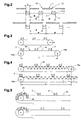
- FIG. 1 schematically shows a conveyor device according to the invention.
- the conveying device 1 is set up for transferring products 2 from a feeding device 3 to a processing device 4.
- the processing device 4 is, for example, a packaging device such as a foiling machine.
- an acceleration or deceleration device 17 may be arranged in the product stream.
- the feeding device 3 deposits the products 2 individually or as a stack or partial stack on support means 13 or product carriers, for example sheets. Run between and parallel to these support means 13, preferably on own funding, cams 6, 9, which form interspaces between the cams or compartments 12 for storing the products 2.
- cams 6, 9 which form interspaces between the cams or compartments 12 for storing the products 2.
- 12 individual products or stacks of products are stored in the subjects.
- the stacks can be placed in the compartments 12 as a whole by the feeder 3, or formed successively by a series of multiple feeders 3 (not shown) by stacking several products in the same compartment 12.
- the cams are sliding cams 9, which push the products 2 on trailing product edges 22 in the conveying direction, and on the other hand leading cams 6, which limit the movement of the products 2 at leading product edges 21 in the conveying direction.
- the length of the products 2 in the conveying direction corresponds to the length of the compartments 12, that is the distance between each successive leading cam 6 and slide cam 9.
- the length of the compartments is preferably equal to or slightly longer than the product length. When products of 2 different lengths are stacked or stacked, the length of the longest product 2 is significant.
- the cams may be fixed relative to the respective conveyor, or such that they may appear or descend at certain points of their path, for example, controlled by a link.
- FIG. 2 schematically shows various settings of a pitch D between successive sliding cam 9 and thus also between successive trailing edge product 22.
- the pitch D can be adapted to different product length respectively compartment length A, B.
- This product distance C can be predetermined by the subsequent machining process. In particular, it may be desirable that the product distance C does not depend on the product length A, B. Otherwise, short products would lead to longer product intervals.
- FIG. 3 shows a schematic diagram of an embodiment of the invention with a length-adjustable and thereby elastic tension element 14 in two positions.
- the tension element is preferably an elastic rope or band 14, for example made of rubber or plastic. It bypasses at least two deflection rollers 19a, which form the transition from the conveying path 18 on the working strand to the return strand and determine a length L of the conveying path 18. Between the pulleys 19 a, the rope or belt 14 extends substantially linearly, whereby it can also be supported by (not shown) support rollers or support rails. At least one of the deflection rollers 19a is displaceable along this linear direction, so that the distance between the deflection rollers 19a can be adjusted.
- the tray length A, B is adjustable in a simple manner.
- that deflection roller 19a which is located on the side for transferring the products 2 to the processing device 4, fixedly arranged, and the opposite guide roller 19a with its axis in the longitudinal direction of the conveying path 18 is movable.
- FIG. 4 shows a schematic diagram of an embodiment of the invention with a length-adjustable conveyor element 15 in two positions.
- the conveying element 15 conveys the alignment elements 5 and is designed as a buffer chain construction, ie with an adjustable distance between the chain links.
- the change in length of the tension element and the distribution of the change in length to the compartment length A, B is preferably effected by means of a slide control (not shown).
- FIG. 5 shows a schematic diagram of an embodiment of the invention with freely definable cam intervals, in operation with a first and a second product spacing:
- the alignment 5 are optional by a clamping mechanism or locking mechanism to a conveyor, in particular a flexible but not substantially elastic conveyor such as a pull rope Coupling is controlled by means of a release device 24.
- a release device 24 In front of the release device 24, returning alignment elements 5 are retained in a storage position 23 and released in a controlled manner, so that the desired compartment length A, B is created. Detecting the length of the compartment and releasing the alignment elements 5 can be effected by mechanical, electrical, pneumatic or by a combination of such elements.
- FIG. 6 schematically shows a variant of the embodiments of Figures 3 or 4 in two positions.
- the two pulleys 19 a are stationary and the length adjustment is achieved by adjusting at least one other roller or tension roller 19 b, via which the return strand 20 leads.
- the axis of the tension roller 19b is displaced perpendicular to the connecting line between the guide rollers 19a.
- An analogous effect can also be achieved with more than one tensioning roller 19b.
- This tension principle can also be applied to the embodiment of FIG. 4 be applied.
- FIG. 7 shows different cam shapes.
- a leading cam 6 is chamfered on the rear side or trailing surface 7, respectively provided with an inclined surface 8.
- a sliding cam 9 has at the front or leading surface 10 a forwardly inclined in the conveying direction alignment surface 11. By the front inclined surface 11, the products 2 are better held together with their trailing edges 22 products.
- the leading and trailing surfaces are perpendicular to the conveying direction.
- the sliding cam 9 is larger than the leading cam 6 is formed to accommodate greater forces.
- FIG. 8 schematically shows a plan view of a conveyor device 1 with parallel pulling members 14 and attached thereto alignment elements 5, and optional support means 13 for receiving and supporting the products.
- tension members and support means straightening or straightening straps 26 are arranged for the lateral alignment of the products 2.
Abstract
Description
Die Erfindung bezieht sich auf das Gebiet der Fördertechnik und insbesondere auf eine Vorrichtung und ein Verfahren zum Fördern und Ausrichten von Gegenständen oder von Stapeln von flachen und optional auch flexiblen Gegenständen wie Druckprodukten gemäss dem Oberbegriff der entsprechenden unabhängigen Patentansprüche.The invention relates to the field of conveyor technology and more particularly to an apparatus and method for conveying and aligning objects or stacks of flat and optionally also flexible articles such as printed products according to the preamble of the respective independent claims.
Eine derartige Förder- und Ausrichtevorrichtung ist beispielsweise aus
Aus
Es ist deshalb Aufgabe der Erfindung, eine Vorrichtung und ein Verfahren zum Ausrichten von Produkten oder von Stapeln von flachen und optional auch flexiblen Gegenständen wie Druckprodukten der eingangs genannten Art zu schaffen, welche die oben genannten Nachteile behebt.It is therefore an object of the invention to provide a device and a method for aligning products or stacks of flat and optionally also flexible objects such as printed products of the type mentioned, which overcomes the disadvantages mentioned above.
Diese Aufgabe lösen eine Vorrichtung und in Verfahren zum Ausrichten von Produkten oder von Stapeln von flachen und optional auch flexiblen Gegenständen, insbesondere Druckprodukten mit den Merkmalen der entsprechenden unabhängigen Patentansprüche.This object is achieved by a device and in methods for aligning products or stacks of flat and optionally also flexible articles, in particular printed products with the features of the corresponding independent patent claims.
Die Fördervorrichtung zum Fördern und Ausrichten von Produkten oder von Stapeln von flachen Produkten weist vorlaufende Nocken zum Anschlag an eine vorlaufende Kante der Produkte auf, sowie nachlaufende Nocken oder Schiebenocken zum Anschlag an eine nachlaufende Kante der Produkte. Die Produkte sind zwischen die vorlaufenden und nachlaufenden Nocken einlegbar und dadurch ausgerichtet. Dabei ist ein Abstand zwischen aufeinander folgenden Schiebenocken verstellbar, ohne dass Teile der Vorrichtung ausgetauscht zu werden brauchen.The conveyor for conveying and aligning products or stacks of flat products has leading cams for abutting a leading edge of the products, and trailing cams or sliding cams for abutting a trailing edge of the products. The products can be inserted between the leading and trailing cams and thereby aligned. In this case, a distance between successive sliding cam is adjustable without needing to be replaced parts of the device.
Der Abstand zwischen aufeinander folgenden Schiebenocken ist gleich dem Abstand zwischen den nachlaufenden Kanten der Produkte, und wird im Folgenden auch Taktabstand genannt. Es ist also möglich, den Taktabstand zu variieren. Damit kann der Taktabstand an die Länge der Produkte in Förderrichtung angepasst werden. Diese Produktlänge ist ungefähr gleich oder leicht kleiner als eine Fachlänge, definiert durch den Abstand zwischen einer vorlaufenden Nocke und der nachfolgenden Schiebenocke. Wäre der Taktabstand nicht verstellbar, so würde bei Produkten mit geringerer Länge der Abstand zwischen benachbarten Produkten, im Folgenden auch Produktabstand genannt, vergrössert. Für Bearbeitungsvorrichtungen wie z.B. Verpackungsmaschinen wie Foliermaschinen, die durch die Fördervorrichtung versorgt werden, ist jedoch erwünscht oder gefordert, dass der Produktabstand gleich ist, ungeachtet der Produktlänge. Indem der Taktabstand anpassbar ist, kann der Produktabstand auch bei unterschiedlichen Produktlängen konstant gehalten oder, allgemeiner gesprochen, unabhängig von der Produktlänge auf einen vorgegebenen Wert eingestellt werden.The distance between successive sliding cams is equal to the distance between the trailing edges of the products, and is also referred to as pitch below. It is thus possible to vary the pitch. Thus, the pitch can be adapted to the length of the products in the conveying direction. This product length is approximately equal to or slightly less than a shelf length defined by the distance between a leading cam and the subsequent sliding cam. If the pitch were not adjustable, the distance between adjacent products, in the case of shorter length products, would be reduced Also called product distance below, enlarged. However, for processing devices such as packaging machines such as filming machines supplied by the conveyor, it is desirable or required that the product distance be the same regardless of the product length. By the pitch is adaptable, the product spacing can be kept constant even with different product lengths or, more generally, adjusted to a predetermined value regardless of the product length.
Das Einstellen der Vorrichtung auf einen unterschiedlichen Taktabstand geschieht, ohne dass die Vorrichtung demontiert und Teile wie Förderketten mit unterschiedlichen Nockenabständen ausgetauscht werden müssen. Damit ist ein schnelles Umrüsten der Vorrichtung auf unterschiedliche Produktelängen möglich. Es muss jedoch nicht unbedingt möglich sein, den Taktabstand während des Betriebs der Vorrichtung anzupassen. Mit anderen Worten kann es erforderlich sein, die Vorrichtung anzuhalten, um den Taktabstand zu verändern.The setting of the device to a different pitch is done without the device dismantled and parts such as conveyor chains with different cam intervals must be replaced. For a quick conversion of the device to different product lengths is possible. However, it may not necessarily be possible to adjust the pitch during operation of the device. In other words, it may be necessary to stop the device to change the pitch.
Vorzugsweise sind jeweils eine Schiebenocke und eine darauf folgende vorlaufende Nocke fest miteinander verbunden. Dadurch bilden sie zusammen eine Einheit, Ausrichtelement genannt, und werden miteinander bewegt. Der Produktabstand zwischen aufeinander folgenden Produkten respektive Produktestapeln wird durch die Länge der Ausrichtelemente in Förderrichtung bestimmt. Der Taktabstand und die Fachlänge (entsprechend der Produktlänge) sind durch den Abstand der Ausrichtelemente voneinander bestimmt. Vorzugsweise sind die Ausrichtelemente einstückig, wobei also ihre vorlaufende Fläche wie eine Schiebenocke wirkt, und die nachlaufende Fläche als vorlaufende Nocke.Preferably, in each case a sliding cam and a subsequent leading cam are firmly connected to each other. As a result, they together form a unit called alignment element and are moved together. The product distance between successive products or product stacks is determined by the length of the alignment elements in the conveying direction. The pitch and the compartment length (corresponding to the product length) are determined by the distance of the alignment elements from each other. Preferably, the alignment elements are in one piece, so that their leading surface acts like a sliding cam, and the trailing surface acts as a leading cam.
In einer anderen bevorzugten Ausführungsform der Erfindung ist der Produktabstand verstellbar. Diese Verstellbarkeit kann beispielsweise realisiert werden, indem die Ausrichtelemente jeweils einzeln gefördert sind, und dabei in sich gegeneinander verschiebbare vorlaufende und nachlaufende Nocken aufweisen. Deren Abstand wird beispielsweise durch eine Kulissensteuerung gesteuert. Alternativ können die vorlaufenden und nachlaufenden Nocken jeweils unabhängig durch eigene, separate Fördermittel transportiert sein, wie sie im Folgenden für die Ausrichtelemente beschrieben sind. Dabei ist also nebst dem Abstand zwischen den einzelnen Nocken eines Fördermittels auch der Versatz zwischen den Nocken der separaten Fördermittel vorgebbar und einstellbar.In another preferred embodiment of the invention, the product distance is adjustable. This adjustability can be realized, for example, by the alignment elements are each conveyed individually, and thereby have mutually displaceable leading and trailing cams. Their distance becomes for example, controlled by a link control. Alternatively, the leading and trailing cams can each be transported independently by their own, separate funding, as described below for the alignment elements. Thus, in addition to the distance between the individual cams of a conveying means, the offset between the cams of the separate conveying means can also be predetermined and set.
In einer bevorzugten Ausführungsform der Erfindung sind die Schiebenocken zur Erzielung eines verstellbaren Abstandes in gleichmässigen Abständen an einem umlaufenden Fördermittel angebracht, und ist der Abstand durch Verstellen der Länge des Fördermittels einstellbar. Dabei ist das Fördermittel derart gestaltet, dass eine Längenänderung des gesamten Fördermittels sich gleichmässig und proportional über die Länge verteilt. Der Abstand zwischen jeweils aufeinander folgenden Nocken verlängert sich also bei allen Nocken um den gleichen Anteil.In a preferred embodiment of the invention, the sliding cam to achieve an adjustable distance at regular intervals attached to a rotating conveyor, and the distance by adjusting the length of the conveyor is adjustable. In this case, the conveying means is designed such that a change in length of the entire conveyor is distributed uniformly and proportionally over the length. The distance between each successive cam thus extends for all cams by the same proportion.
Wenn nur Ausrichtelemente vorliegen, also kombinierte vorlaufende Nocken und Schiebenocken, so sind diese mittels eines einzigen Fördermittels förderbar. In der Praxis werden in der Regel zwei oder mehr parallel, seitlich voneinander verlaufende Fördermittel mit parallel und synchron zueinander bewegten Nocken vorliegen. Wenn die vorlaufenden Nocken und die Schiebenocken voneinander getrennt, als separate Teile vorliegen, können sie auch auf separaten Fördermitteln gefördert werden. Sie werden dann zueinander phasenverschoben gefördert. Beim Verstellen der Länge der Fördermittel geschieht dies synchron für beide Fördermittel. Auch hier werden in der Praxis zumindest für die Schiebenocken und vorzugsweise auch für die vorlaufenden Nocken jeweils zwei oder mehr parallel und synchron verlaufende Nockensätze vorliegen.If only aligning elements are present, that is to say combined leading cams and sliding cams, these can be conveyed by means of a single conveying means. In practice, there will usually be two or more parallel, laterally spaced conveying means with cams moving in parallel and synchronously with each other. When the leading cams and the sliding cams are separated from each other as separate parts, they can be conveyed on separate conveyors. They are then promoted out of phase with each other. When adjusting the length of the funding this happens synchronously for both funding. Again, two or more parallel and synchronous cam sets will be present in practice at least for the shift cams and preferably also for the leading cams.
In einer ersten bevorzugten Variante dieser Ausführungsform ist das umlaufende Fördermittel flexibel und elastisch und ist der Abstand durch Dehnen des Fördermittels einstellbar. Das Fördermittel kann ein Seil oder ein Band, oder eine Gruppe von Seilen oder Bändern sein und beispielsweise aus einem elastischen Kunststoff oder aus Metallfedern gebildet sein, welche die aufeinander folgenden Nocken miteinander verbinden. Das Fördermittel läuft beispielsweise um zwei Umlenkrollen um, wobei die Längenverstellung durch Verstellen des Abstandes zwischen den Umlenkrollen geschieht, vorzugsweise durch Verschieben einer Lagerachse einer der Umlenkrollen.In a first preferred variant of this embodiment, the circulating conveyor is flexible and elastic and the distance is adjustable by stretching the conveyor. The conveyor may be a rope or a belt, or a Group of ropes or straps and be formed for example of a resilient plastic or metal springs, which connect the successive cams together. The conveyor runs around, for example, two deflection rollers, the length adjustment being effected by adjusting the distance between the deflection rollers, preferably by displacing a bearing axis of one of the deflection rollers.
In einer zweiten bevorzugten Variante dieser Ausführungsform ist das umlaufende Fördermittel eine Pufferkette, d.h. eine Kette mit verstellbarem Abstand zwischen den Kettengliedern, und ist der Abstand durch Steuerkulissen des Fördermittels einstellbar. Solche Pufferketten oder Fördervorrichtungen mit kontrollierbarem Abstand zwischen einzelnen Förderelementen sind beispielsweise in den veröffentlichten Patentschriften
Vorzugsweise geschieht auch hier das Verstellen der Länge des Fördermittels durch Verändern der Länge einer linearen Förderstrecke, um welche das Fördermittel umläuft, also einer Förderstrecke, die mit einem Obertrum (oder Arbeitstrum) und einem Rücktrum linear zwischen zwei Umlenkelementen verläuft. Alternativ können bei beiden Varianten die Umlenkelemente am Ende der Förderstrecke unbeweglich sein, und das Fördermittel im Rücktrum mit den Nocken um eine oder mehrere weitere Umlenkrollen oder Spannrollen geführt sein, deren Achsposition zum Verstellen der Länge des Fördermittels verschiebbar ist.Preferably, also here, the adjustment of the length of the conveying means by changing the length of a linear conveying path, around which the conveyor rotates, ie a conveying path, which runs with a top run (or workstrum) and a return run linearly between two deflecting elements. Alternatively, in both variants, the deflecting elements can be immovable at the end of the conveying path, and the conveying means in the return strand with the cams can be guided around one or more further deflection rollers or tensioning rollers whose axial position is displaceable for adjusting the length of the conveying means.
In einer anderen bevorzugten Ausführungsform der Erfindung sind die Nocken (entweder die Ausrichtelemente, oder jeweils separat die Schiebenocken und die vorlaufenden Nocken) zum wahlweisen Ankoppeln an oder Abkoppeln von einem umlaufenden Fördermittel ausgebildet, entsprechend dem gewünschten Abstand zwischen den Nocken. In einer Speicherstellung sind sie vom Fördermittel abgekoppelt sind, und durch eine Freigabevorrichtung sind sie in wählbaren Abständen an das Fördermittel ankoppelbar. Falls die Nocken Ausrichtelemente sind, ist dieser Abstand gleich dem Taktabstand. Falls die Nocken separate Schiebenocken und vorlaufende Nocken sind, die am gleichen Fördermittel transportiert werden, ist dieser Abstand abwechslungsweise der Produktabstand und die Produktlänge. Es ist jedoch auch möglich, dass Schiebenocken und vorlaufende Nocken seitlich versetzt auf separaten Fördermitteln gefördert werden. Die Abstände sind dann bei jedem Fördermittel jeweils gleich dem Taktabstand, jedoch sind die Schiebenocken gegenüber den vorlaufenden Nocken um die Produktlänge respektive Fachlänge phasenverschoben. Beispiele für Fördervorrichtungen mit einzeln abrufbaren Mitnehmern sind in der
Das Verfahren zum Fördern und Ausrichten von Produkten oder von Stapeln von flachen Produkten weist die Schritte auf:
- Schieben der Produkte an ihren nachlaufenden Kanten mittels nachlaufender Nocken oder Schiebenocken;
- Zurückhalten der Produkte an ihren vorlaufenden Kanten mittels vorlaufender Nocken;
- Ausrichten der Produkte durch die Schiebenocken und die vorlaufenden Nocken;
- Einstellen eines Abstandes aufeinander folgender Produkte durch den Abstand zwischen jeweils einer Schiebenocke und der darauf folgenden, das nächste Produkt zurückhaltende vorlaufenden Nocke, wobei die Schiebenocke und die darauf folgende vorlaufende Nocke fest miteinander verbunden sind und so miteinander ein sowohl an seiner vorlaufenden wie auch an seiner nachlaufenden Seite wirkendes Ausrichtelement bilden.
- Pushing the products at their trailing edges by means of trailing cams or sliding cams;
- Retaining the products at their leading edges by means of leading cams;
- Aligning the products with the sliding cams and the leading cams;
- Adjusting a distance of successive products by the distance between each one sliding cam and the next leading cam retenting the next product, the sliding cam and the subsequent leading cam being fixedly connected to each other, both at its leading and trailing edges forming the trailing side acting alignment.
In den beschriebenen Ausführungsformen der Erfindung versteht sich, dass das Fördern der Produkte jeweils durch Bewegung der Produkte in eine gleich bleibende Förderrichtung geschieht, also nicht durch hin- und herbewegen der Produkte. Vorzugsweise ist zudem die Bewegung der Nocken im wesentlichen kontinuierlich, also von mindestens annähernd konstanter Geschwindigkeit, und nicht schrittweise. Weitere bevorzugte Ausführungsformen gehen aus den abhängigen Patentansprüchen hervor. Dabei sind Merkmale der Verfahrensansprüche sinngemäss mit den Vorrichtungsansprüchen kombinierbar und umgekehrt.In the described embodiments of the invention, it is understood that the conveying of the products takes place in each case by movement of the products in a constant conveying direction, that is not by reciprocating the products. In addition, the movement of the cams is preferably essentially continuous, that is to say of at least approximately constant speed, and not stepwise. Further preferred embodiments emerge from the dependent claims. Characteristics of the method claims are analogously combined with the device claims and vice versa.
Im folgenden wird der Erfindungsgegenstand anhand von bevorzugten Ausführungsbeispielen, welche in den beiliegenden Zeichnungen dargestellt sind, näher erläutert. Es zeigen jeweils schematisch:
- Figur 1
- eine Fördervorrichtung gemäss der Erfindung;
Figur 2- verschiedene Einstellungen eines Taktabstandes;
Figur 3- eine Prinzipskizze einer Ausführungsform der Erfindung mit einem elastischen Zugelement;
- Figur 4
- eine Prinzipskizze einer Ausführungsform der Erfindung mit einem längenverstellbaren Zugelement;
Figur 5- eine Prinzipskizze einer Ausführungsform der Erfindung mit frei vorgebbaren Nockenabständen;
Figur 6- eine Variante der Ausführungsform der
Figuren 3 oder 4 ; Figur 7- verschiedene Nockenformen; und
Figur 8- eine Aufsicht auf eine Fördervorrichtung.
- FIG. 1
- a conveyor device according to the invention;
- FIG. 2
- different settings of a pitch;
- FIG. 3
- a schematic diagram of an embodiment of the invention with an elastic tension element;
- FIG. 4
- a schematic diagram of an embodiment of the invention with a length-adjustable tension element;
- FIG. 5
- a schematic diagram of an embodiment of the invention with freely definable cam intervals;
- FIG. 6
- a variant of the embodiment of the
Figures 3 or 4 ; - FIG. 7
- different cam shapes; and
- FIG. 8
- a view of a conveyor.
Die in den Zeichnungen verwendeten Bezugszeichen und deren Bedeutung sind in der Bezugszeichenliste zusammengefasst aufgelistet. Grundsätzlich sind in den Figuren gleiche Teile mit gleichen Bezugszeichen versehen.The reference numerals used in the drawings and their meaning are listed in the list of reference numerals. Basically, the same parts are provided with the same reference numerals in the figures.
Die Zuführvorrichtung 3 legt die Produkte 2 einzeln oder als Stapel oder Teilstapel auf Auflagemittel 13 oder Produktträger, beispielsweise Bleche, ab. Zwischen und parallel zu diesen Auflagemitteln 13 verlaufen, an vorzugsweise eigenen Fördermitteln, Nocken 6, 9, welche zwischen den Nocken liegende Zwischenräume oder Fächer 12 zur Ablage der Produkte 2 bilden. Hier und im Folgenden sind in den Fächern 12 einzelne Produkte oder Stapel von Produkten abgelegt. Die Stapel können durch die Zuführvorrichtung 3 als Ganzes in die Fächer 12 abgelegt werden, oder durch eine Folge von mehreren Zuführvorrichtungen 3 (nicht gezeichnet) durch Aufeinanderlegen mehrerer Produkte in dasselbe Fach 12 sukzessive gebildet werden.The
Die Nocken sind einerseits Schiebenocken 9, welche die Produkte 2 an nachlaufenden Produktekanten 22 in Förderrichtung schieben, und andererseits vorlaufende Nocken 6, welche die Bewegung der Produkte 2 an vorlaufenden Produktekanten 21 in Förderrichtung begrenzen. Die Länge der Produkte 2 in Förderrichtung entspricht der Länge der Fächer 12, also dem Abstand zwischen jeweils aufeinander folgenden vorlaufenden Nocken 6 und Schiebenocken 9. Die Länge der Fächer ist vorzugsweise gleich oder etwas länger als die Produktlänge. Wenn Produkte 2 unterschiedlicher Länge gestapelt sind oder gestapelt werden, ist die Länge des längsten Produktes 2 massgebend.On the one hand, the cams are sliding
Die Nocken können, relativ zum jeweiligen Fördermittel, fest angeordnet sein, oder derart, dass sie, beispielsweise durch eine Kulisse gesteuert, an bestimmten Stellen ihrer Bahn auftauchen oder abtauchen.The cams may be fixed relative to the respective conveyor, or such that they may appear or descend at certain points of their path, for example, controlled by a link.
- 11
- Fördervorrichtungconveyor
- 22
- Produktproduct
- 33
- Zuführvorrichtungfeeder
- 44
- Bearbeitungsvorrichtungprocessing device
- 55
- Richtnocke, AusrichtelementRichtnocke, alignment element
- 66
- vorlaufender Anschlagleading stop
- 77
- nachlaufende FlächeTrailing surface
- 88th
- schräge Flächesloping surface
- 99
- nachlaufender Anschlag, Schiebenockentrailing stop, sliding cam
- 1010
- vorlaufende Flächeleading surface
- 1111
- vorwärts geneigte Ausrichtflächeforwardly inclined alignment surface
- 1212
- Fachsubject
- 1313
- Auflagemittelsupport means
- 1414
- elastisches Seilelastic rope
- 1515
- Förderelementimpeller
- 1717
- Beschleunigungs- oder VerzögerungseinrichtungAcceleration or deceleration device
- 1818
- Förderstreckeconveyor line
- 19a19a
- Umlenkrollenguide rollers
- 19b19b
- Spannrollentensioners
- 2020
- Rückweg, RücktrumWay back, return
- 2121
- vorlaufende Produktekanteleading edge of the product
- 2222
- nachlaufende Produktekantetrailing edge of the product
- 2323
- Speicherstellungstorage position
- 2424
- Freigabevorrichtungrelease device
- 2525
- Zugseil (nicht elastisch)Pull rope (not elastic)
- 2626
- Richtblechestraightening plates
- A, BA, B
- Abstand zwischen Schiebenocken, FachlängeDistance between sliding cam, shed length
- CC
- Produkteabstandproducts distance
- DD
- Taktabstandpitch
- LL
- Länge der FörderstreckeLength of the conveyor line
Claims (15)
dadurch gekennzeichnet, dass ein Abstand (D) zwischen aufeinander folgenden Schiebenocken (9) verstellbar ist, ohne dass Teile der Vorrichtung (1) ausgetauscht zu werden brauchen.Conveying device (1) for conveying and aligning flat and optionally flexible products (1) or stacks of flat products (2), comprising leading cams (6) for abutting a leading edge (21) of conveyed products (2), and trailing cam or sliding cam (9) for abutment with a trailing edge (22) of the conveyed products (2), wherein the products (2) between the leading and trailing cams (6, 9) are inserted and so by the cams (6, 9) are promoted and aligned,
characterized in that a distance (D) between successive sliding cam (9) is adjustable without parts of the device (1) need to be replaced.
Applications Claiming Priority (1)
| Application Number | Priority Date | Filing Date | Title |
|---|---|---|---|
| CH01537/08A CH699597A1 (en) | 2008-09-29 | 2008-09-29 | Conveying means for conveying and orienting flat and optional flexible products or stacks of flat products. |
Publications (2)
| Publication Number | Publication Date |
|---|---|
| EP2210841A2 true EP2210841A2 (en) | 2010-07-28 |
| EP2210841A3 EP2210841A3 (en) | 2010-12-29 |
Family
ID=40340470
Family Applications (1)
| Application Number | Title | Priority Date | Filing Date |
|---|---|---|---|
| EP09405167A Withdrawn EP2210841A3 (en) | 2008-09-29 | 2009-09-25 | Conveyor comprising aligning cams |
Country Status (5)
| Country | Link |
|---|---|
| US (1) | US8061505B2 (en) |
| EP (1) | EP2210841A3 (en) |
| AU (1) | AU2009222520A1 (en) |
| CA (1) | CA2680631A1 (en) |
| CH (1) | CH699597A1 (en) |
Cited By (1)
| Publication number | Priority date | Publication date | Assignee | Title |
|---|---|---|---|---|
| DE102010022126A1 (en) * | 2010-05-20 | 2011-11-24 | Krones Ag | Conveyor chain for transporting preforms or containers in oven in food industry, has mechanical adjusting unit e.g. control cam, changing distances between holding devices, which are arranged between chain links |
Families Citing this family (2)
| Publication number | Priority date | Publication date | Assignee | Title |
|---|---|---|---|---|
| CH703561A1 (en) | 2010-08-06 | 2012-02-15 | Ferag Ag | Apparatus for aligning a sheet-like product. |
| US8596629B2 (en) * | 2011-11-03 | 2013-12-03 | Pitney Bowes Inc. | Adaptive registration/binding apparatus for preparing collations |
Citations (9)
| Publication number | Priority date | Publication date | Assignee | Title |
|---|---|---|---|---|
| US4502592A (en) | 1982-02-13 | 1985-03-05 | E.C.H. Will (Gmbh & Co.) | Apparatus for intermittently transporting stacks of paper sheets or the like |
| DE3335583A1 (en) | 1983-09-30 | 1985-04-18 | Maschinenbau Oppenweiler Gmbh, 7155 Oppenweiler | Feed apparatus for the intermittent displacement of piles of sheets, especially of folded booklets |
| EP0276409A2 (en) | 1987-01-26 | 1988-08-03 | Ferag AG | Conveyor for intermittent transport |
| EP0300170A1 (en) | 1987-07-21 | 1989-01-25 | Ferag AG | Method and device for separating products in overlapping streams, in particular printed products |
| EP0309702A1 (en) | 1987-10-02 | 1989-04-05 | Ferag AG | Continuous conveyor for articles |
| US5072573A (en) | 1990-01-12 | 1991-12-17 | Tisma Machine Corporation | Apparatus with adjustable width trays for automatic packaging machines |
| US6293544B1 (en) | 1999-12-22 | 2001-09-25 | Xerox Corporation | Apparatus and method for registering and conveying a compiled set of sheets |
| US20030136086A1 (en) | 2001-12-05 | 2003-07-24 | Kalany Robert M. | Packaging apparatus and methods |
| EP1410992A1 (en) | 2002-10-14 | 2004-04-21 | SITMA S.p.A. | Aligning device and method for feeding products into an automatic packaging machine |
Family Cites Families (14)
| Publication number | Priority date | Publication date | Assignee | Title |
|---|---|---|---|---|
| US3057456A (en) * | 1959-08-04 | 1962-10-09 | Sig Schweiz Industrieges | Endless type conveyer |
| DE1150021B (en) * | 1959-08-04 | 1963-06-06 | Sig Schweiz Industrieges | Conveyor device with the following entrainment organs at adjustable intervals |
| US3040634A (en) * | 1960-04-27 | 1962-06-26 | Fmc Corp | Carton set-up mechanism |
| FR1465356A (en) * | 1961-11-07 | 1967-01-13 | Remy & Cie E P | Device for grouping a set number of various objects |
| US3368660A (en) * | 1966-11-25 | 1968-02-13 | Johns Nigrelli Johns | Article grouper and feeder |
| US3872647A (en) * | 1973-03-22 | 1975-03-25 | Marinus J M Langen | Carton loader |
| US3896711A (en) * | 1974-03-13 | 1975-07-29 | Container Corp | Apparatus for erecting carton tubes |
| CA1009175A (en) * | 1974-04-19 | 1977-04-26 | Arthur G. Alsop | Stacking mechanism and method |
| US4552261A (en) * | 1983-12-27 | 1985-11-12 | Standard-Knapp, Inc. | Article grouper for case packer |
| US5081821A (en) * | 1988-11-16 | 1992-01-21 | Pemco Company | Method and apparatus for manipulating stacks of paper sheets in wrapping machines |
| GB9421177D0 (en) * | 1994-10-20 | 1994-12-07 | Riverwood Int Ltd | Spacing conveyor mechanism |
| US5806659A (en) * | 1996-10-18 | 1998-09-15 | Bell And Howell Mail Processing Systems | Chain apparatus for high-speed media processing |
| DE102005026639B4 (en) * | 2005-06-09 | 2009-01-08 | Khs Ag | Device for splitting, lashing and grouping of piece goods |
| GB2436550A (en) * | 2006-03-31 | 2007-10-03 | Meadwestvaco Packaging Systems | Releasably engaging lugs and means of positioning the lugs |
-
2008
- 2008-09-29 CH CH01537/08A patent/CH699597A1/en not_active Application Discontinuation
-
2009
- 2009-09-24 CA CA2680631A patent/CA2680631A1/en not_active Abandoned
- 2009-09-25 EP EP09405167A patent/EP2210841A3/en not_active Withdrawn
- 2009-09-28 US US12/568,405 patent/US8061505B2/en not_active Expired - Fee Related
- 2009-09-29 AU AU2009222520A patent/AU2009222520A1/en not_active Abandoned
Patent Citations (9)
| Publication number | Priority date | Publication date | Assignee | Title |
|---|---|---|---|---|
| US4502592A (en) | 1982-02-13 | 1985-03-05 | E.C.H. Will (Gmbh & Co.) | Apparatus for intermittently transporting stacks of paper sheets or the like |
| DE3335583A1 (en) | 1983-09-30 | 1985-04-18 | Maschinenbau Oppenweiler Gmbh, 7155 Oppenweiler | Feed apparatus for the intermittent displacement of piles of sheets, especially of folded booklets |
| EP0276409A2 (en) | 1987-01-26 | 1988-08-03 | Ferag AG | Conveyor for intermittent transport |
| EP0300170A1 (en) | 1987-07-21 | 1989-01-25 | Ferag AG | Method and device for separating products in overlapping streams, in particular printed products |
| EP0309702A1 (en) | 1987-10-02 | 1989-04-05 | Ferag AG | Continuous conveyor for articles |
| US5072573A (en) | 1990-01-12 | 1991-12-17 | Tisma Machine Corporation | Apparatus with adjustable width trays for automatic packaging machines |
| US6293544B1 (en) | 1999-12-22 | 2001-09-25 | Xerox Corporation | Apparatus and method for registering and conveying a compiled set of sheets |
| US20030136086A1 (en) | 2001-12-05 | 2003-07-24 | Kalany Robert M. | Packaging apparatus and methods |
| EP1410992A1 (en) | 2002-10-14 | 2004-04-21 | SITMA S.p.A. | Aligning device and method for feeding products into an automatic packaging machine |
Cited By (3)
| Publication number | Priority date | Publication date | Assignee | Title |
|---|---|---|---|---|
| DE102010022126A1 (en) * | 2010-05-20 | 2011-11-24 | Krones Ag | Conveyor chain for transporting preforms or containers in oven in food industry, has mechanical adjusting unit e.g. control cam, changing distances between holding devices, which are arranged between chain links |
| DE102010022126A9 (en) * | 2010-05-20 | 2017-04-27 | Krones Aktiengesellschaft | Automatic adjustment of the division of a conveyor chain |
| DE102010022126B4 (en) * | 2010-05-20 | 2021-03-25 | Krones Aktiengesellschaft | Automatic setting of the pitch of a conveyor chain |
Also Published As
| Publication number | Publication date |
|---|---|
| CA2680631A1 (en) | 2010-03-29 |
| US8061505B2 (en) | 2011-11-22 |
| EP2210841A3 (en) | 2010-12-29 |
| CH699597A1 (en) | 2010-03-31 |
| AU2009222520A1 (en) | 2010-04-15 |
| US20100078292A1 (en) | 2010-04-01 |
Similar Documents
| Publication | Publication Date | Title |
|---|---|---|
| EP0550828B1 (en) | Method and device for handling printed products | |
| EP1119507B1 (en) | Device for receiving and transporting objects | |
| DE2938010C2 (en) | Device for aligning objects fed in an uninterrupted, closed row | |
| EP0510525B1 (en) | Method and device for handling printed products | |
| EP0503531A1 (en) | Device for realising a formation of underlapping objects | |
| EP2428471B1 (en) | Conveying system | |
| EP1320501A1 (en) | Method and device for transferring a product in a packing machine | |
| EP1118564B1 (en) | Transport device | |
| DE1813817C3 (en) | Device for separating and conveying flat objects running in an uninterrupted row | |
| EP1169249B1 (en) | Method and device for conveying unit loads | |
| EP0944544B1 (en) | Method and device for conveying individually held products | |
| DE102016109226A1 (en) | Device and method for the defined unification, distribution and / or redistribution of parcels and / or parcel groups | |
| CH680851A5 (en) | ||
| DE60221268T2 (en) | DELIVERY DEVICE FOR CYLINDRICAL STACK OF PRODUCTS ARRANGED ON A RIM | |
| EP2210841A2 (en) | Conveyor comprising aligning cams | |
| EP0478911A1 (en) | Device for the selective transfer of overlapping articles from a first conveyor to a second conveyor | |
| DE102017004232A1 (en) | Object transport device | |
| EP1231176B1 (en) | Device for feeding printed products in a conveyor duct | |
| EP2228332B1 (en) | Device and method for taking over flexible flat products | |
| DE1561141B2 (en) | DEVICE FOR INSERTING INSERTS INTO FOLDED PRINT PRODUCTS | |
| EP2346764B1 (en) | Apparatus and corresponding method for conveying and handing over of flat articles | |
| EP0499691A1 (en) | Method for handling printed products fed in a continuous overlapping formation and device for carrying out said method | |
| EP0458733B1 (en) | Method and device for transporting printed products | |
| EP2418164B1 (en) | Method and device for gathering flat products with other flat products and device for conveying flat products, in particular printed products | |
| EP1274639B1 (en) | Device for conveying flat objects |
Legal Events
| Date | Code | Title | Description |
|---|---|---|---|
| PUAI | Public reference made under article 153(3) epc to a published international application that has entered the european phase |
Free format text: ORIGINAL CODE: 0009012 |
|
| AK | Designated contracting states |
Kind code of ref document: A2 Designated state(s): AT BE BG CH CY CZ DE DK EE ES FI FR GB GR HR HU IE IS IT LI LT LU LV MC MK MT NL NO PL PT RO SE SI SK SM TR |
|
| AX | Request for extension of the european patent |
Extension state: AL BA RS |
|
| PUAL | Search report despatched |
Free format text: ORIGINAL CODE: 0009013 |
|
| AK | Designated contracting states |
Kind code of ref document: A3 Designated state(s): AT BE BG CH CY CZ DE DK EE ES FI FR GB GR HR HU IE IS IT LI LT LU LV MC MK MT NL NO PL PT RO SE SI SK SM TR |
|
| AX | Request for extension of the european patent |
Extension state: AL BA RS |
|
| 17P | Request for examination filed |
Effective date: 20110331 |
|
| STAA | Information on the status of an ep patent application or granted ep patent |
Free format text: STATUS: THE APPLICATION IS DEEMED TO BE WITHDRAWN |
|
| 18D | Application deemed to be withdrawn |
Effective date: 20130403 |