EP2199763A1 - Level Measurement Arrangement - Google Patents
Level Measurement Arrangement Download PDFInfo
- Publication number
- EP2199763A1 EP2199763A1 EP08172559A EP08172559A EP2199763A1 EP 2199763 A1 EP2199763 A1 EP 2199763A1 EP 08172559 A EP08172559 A EP 08172559A EP 08172559 A EP08172559 A EP 08172559A EP 2199763 A1 EP2199763 A1 EP 2199763A1
- Authority
- EP
- European Patent Office
- Prior art keywords
- reflector
- container
- signals
- level
- medium
- Prior art date
- Legal status (The legal status is an assumption and is not a legal conclusion. Google has not performed a legal analysis and makes no representation as to the accuracy of the status listed.)
- Granted
Links
Images


Classifications
-
- G—PHYSICS
- G01—MEASURING; TESTING
- G01F—MEASURING VOLUME, VOLUME FLOW, MASS FLOW OR LIQUID LEVEL; METERING BY VOLUME
- G01F23/00—Indicating or measuring liquid level or level of fluent solid material, e.g. indicating in terms of volume or indicating by means of an alarm
- G01F23/22—Indicating or measuring liquid level or level of fluent solid material, e.g. indicating in terms of volume or indicating by means of an alarm by measuring physical variables, other than linear dimensions, pressure or weight, dependent on the level to be measured, e.g. by difference of heat transfer of steam or water
- G01F23/28—Indicating or measuring liquid level or level of fluent solid material, e.g. indicating in terms of volume or indicating by means of an alarm by measuring physical variables, other than linear dimensions, pressure or weight, dependent on the level to be measured, e.g. by difference of heat transfer of steam or water by measuring the variations of parameters of electromagnetic or acoustic waves applied directly to the liquid or fluent solid material
- G01F23/284—Electromagnetic waves
-
- G—PHYSICS
- G01—MEASURING; TESTING
- G01F—MEASURING VOLUME, VOLUME FLOW, MASS FLOW OR LIQUID LEVEL; METERING BY VOLUME
- G01F23/00—Indicating or measuring liquid level or level of fluent solid material, e.g. indicating in terms of volume or indicating by means of an alarm
- G01F23/22—Indicating or measuring liquid level or level of fluent solid material, e.g. indicating in terms of volume or indicating by means of an alarm by measuring physical variables, other than linear dimensions, pressure or weight, dependent on the level to be measured, e.g. by difference of heat transfer of steam or water
- G01F23/28—Indicating or measuring liquid level or level of fluent solid material, e.g. indicating in terms of volume or indicating by means of an alarm by measuring physical variables, other than linear dimensions, pressure or weight, dependent on the level to be measured, e.g. by difference of heat transfer of steam or water by measuring the variations of parameters of electromagnetic or acoustic waves applied directly to the liquid or fluent solid material
- G01F23/296—Acoustic waves
- G01F23/2962—Measuring transit time of reflected waves
-
- G—PHYSICS
- G01—MEASURING; TESTING
- G01F—MEASURING VOLUME, VOLUME FLOW, MASS FLOW OR LIQUID LEVEL; METERING BY VOLUME
- G01F25/00—Testing or calibration of apparatus for measuring volume, volume flow or liquid level or for metering by volume
- G01F25/20—Testing or calibration of apparatus for measuring volume, volume flow or liquid level or for metering by volume of apparatus for measuring liquid level
Definitions
- the present invention concerns an arrangement for measurement of a level of a medium in a container, comprising a level measurement device comprising a process connector for mounting said device on an opening of the container, an antenna for transmitting signals into said container and for receiving echo signals resulting from reflections of the transmitted signals inside the container, and a measurement electronic, for determining the level of the medium based on a measurement of a transit time needed for the signal to travel to the surface of the medium and of its echo to return to the device.
- Microwave level measurement devices transmit microwave signals through an opening in the container toward the surface of the medium inside and receive echo signals of the transmitted microwaves. From the received echo signals an echo function representing echo amplitude as a function of the distance or time is formed for each measurement. A transit time of a microwave signal to travel from the device to the surface and of its echo to return to the device is determined based on the echo function. The distance between the device and the surface is then determined based on the transit time.
- FMCW-Radar frequency-modulated continuous wave radar
- Pulse radar level measurement devices periodically send short microwave pulses. The transit time between the transmission of the microwave pulse and the reception of its echo is measured and the level is determined based on the transit time.
- FMCW radar level measurement devices transmit a continuous microwave signal, which is periodically linearly frequency modulated.
- the frequency of the received echo signal differs from the frequency of the transmitted signal by an amount, which depends on the transit time between the emission and the reception of the corresponding echo.
- antennas are for example horn antennas comprising a metal horn, rod antennas comprising a dielectric rod or planar antennas using microstrip line technology, as for example described in US-B1 6,266,022 .
- Other measurement device are on the marked for measurement of a level of a medium inside a container based on a measurement of a transit time needed for a signal to travel from the device to the surface of the medium and of its echo signal, caused by a reflection of the transmitted signal on the surface, to return to the device.
- These devices are for example ultrasonic level measurement devices transmitting and receiving ultrasonic signals, or optical measurement devices transmitting and receiving optical signals.
- proper operation and accuracy of the measurement can for example be tested, by raising the level of the medium inside the container on the measurement site to a predefined test level.
- the level measurement device measures this level and the measurement result is compared to the known predefined test level.
- the ongoing production process needs to be interrupted and the predefined test level needs to be determined by another measurement, independently of the measurement device to be tested.
- the waveguide level sensing device transmits electromagnetic pulses along a waveguide into a container and receives an echo signal of this pulse resulting from a reflection of the pulse on the surface of the level inside the waveguide.
- the test apparatus comprises a bridge, which can be moved into a test position, wherein the bridge bridges the waveguide during a test period. If the device functions properly, it will indicate a level corresponding to the level of the bride during test period. After each test period the bridge is moved into a storage position where the waveguide is not bridged. During the test period no level measurements can be performed.
- a level measurement arrangement comprising a level measurement device for measuring a level of a medium inside a container based on a measurement of a transit time needed for a signal to travel from the device to the surface of the medium and of its echo signal, caused by a reflection of the transmitted signal on the surface, to return to the device, which can be tested during normal measurement operation.
- the invention comprises an arrangement for measurement of a level of a medium in a container, comprising:
- the reflector is a flat disc having a long thin rectangular cross section.
- the signals are microwave signals.
- the invention further comprises a method of operating an arrangement according to the invention, wherein
- the invention further comprises an alternative method of operating an arrangement according to the invention, wherein
- the invention further comprises a further method of operating an arrangement according to the invention, wherein
- the invention further comprises a method of calibrating the level measurement device of an arrangement according to the refinement of the invention, comprising the steps of
- the insertion height at which the reflector is inserted into the transmission lobe is adjustable. Measurement accuracy of the device can thus be tested and approved for various different distances between the device and the reflector.
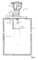
- Fig. 1 shows a microwave level measurement arrangement for measurement of a level of a medium 1 in a container 3. It comprises a level measurement device 5, which is mounted onto an opening on the container 3 via a process connector 7.
- the measurement device 5 is for example a pulse radar measurement device or an FMCW level measurement device as described above.
- microwave level measurement device 5 it is not limited to arrangements comprising microwave level measurement devices.
- other level measurement devices can be used in the arrangements according to the invention, as long as they are designed to measure level by measuring a transit time needed for a signal to travel from the device to the surface of the medium and of its corresponding echo signal, generated by a reflection of the transmitted signal on this surface, to return to the device.
- Such devices are for example ultrasonic level measurement devices transmitting and receiving ultrasonic signals, or optical measurement devices transmitting and receiving optical signals.
- the process connector 7 is a flange, which is mounted onto a corresponding counter part 9 surrounding the opening of the container 3.
- the measurement device 5 comprises an antenna 11 for transmitting microwave signals into the container 3 and for receiving their echo signals resulting from reflections of the transmitted microwave signals inside the container 3.
- the antenna 11 is for example a horn antenna as shown in fig. 1 .
- other types of antennas known in the field can be used, designed to transmit microwave signals into free space and to receive their echo signals, e.g. rod antennas comprising a dielectric rod or planar antennas using microstrip line technology.
- the arrangement further comprises an apparatus for testing the microwave level measurement device 5, in particular for testing the proper operation and/or measurement accuracy of the device 5.
- Central element of this apparatus is a reflector 13 which is inserted into a transmission lobe 15 of the transmitted microwave signals at a predetermined preferably adjustable insertion height inside the container 3.
- the transmission lobe 15 has the shape of a three dimensional cone as indicated in fig. 1 by a dashed line.
- the reflector 13 is dimensioned such, that it covers a fraction of a cross-section 17 of the transmission lobe 15 at its insertion height.
- Fig. 2 shows the cross-section 17 of the transmission lobe 15 at the insertion height shown in fig. 1 and an exemplary embodiment of reflector 13.
- the cross-section 17 of the transmission lobe 15 is circular and the reflector 13 is a flat disc, having a long thin rectangular cross section.
- Mounting means are foreseen for mounting the reflector 13 inside the container 3 above the medium 1.
- the mounting means are mounted onto the process connector 7 via connector 19. This has the advantage, that the reflector 13 can be mounted together with the measurement device 5 and no separate openings need to be provided on the container 3.
- the mounting means comprise an elongated rod shaped holder 21, which extends through the process connector 7 into the container 3, such that a section 23 of the holder 21 is located inside and a section 25 of the holder 21 is located outside the container 3.
- the reflector 13 is mounted on a bottom end of the holder 21 inside the container 3 and extends perpendicular to a longitudinal axis of the holder 21.
- the insertion height of the reflector 13 is given by the length of the section 23 of the holder 21 extending into the container 3.
- connector 19 is a releasable connector which allows for the length of the section 23 inside the container 3 to be adjusted by pushing the holder 21 further into the container 3 or by pulling it further out of the container 3.
- the holder 21 can be positioned and fixed manually or by a positioning device 27, e.g. an actuator or motor attached to the holder 21 including the connector 19.
- a holder 29 can be used comprising a telescopic rod of adjustable length, as shown in fig. 3 .
- the telescopic rod is e.g. entirely located inside the container 3 and mounted onto the process connector 7. Length adjustment can for example be performed by a hydraulic system 31 mounted outside the container 3 on the process connector 7 and connected to the telescopic rod on the inside, via an opening in the process connector 7.
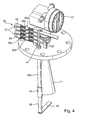
- Fig. 4 shows a further embodiment of mounting means for mounting the reflector 13 at different predetermined insertion heights inside the container 3.
- mounting means comprise a foldable holder 33 for inserting the reflector 13 at different predetermined insertion heights.
- the holder 33 consists of rod shaped segments 35, here segments 35a, 35b, 35c, 35d and 35e, which are interconnected by hinges 37 to form a foldable rod, and a rod shaped end section 39.
- the end section 39 is permanently located inside the container 3 and connected to a first end of the foldable rod, e.g. by an additional hinge.
- Mounting means 41 are foreseen for mounting the holder 33 onto an opening extending through the process connector 7.
- the mounting means 41 comprise an opening through which a selectable number of the segments 35 can be inserted through the process connector 7 into the container 3.
- the segments 35e which are inserted into the container 3 form a straight rod, extending in a straight line with the end section 39 connected thereto.
- Preferably hollow cylindrical caps 43 are foreseen on the holder 33 near each hinge 37, which slide over the respective hinge 37 due to gravity when the hinge 37 is straightened and brought into a vertical position for insertion. The caps 43 then prevent any further movement of the respective hinge 37 after its insertion into the container 3.
- the remaining segments 35a, 35b, 35c, and 35d, which are located outside the container 3 are folded together.
- the reflector 13 is mounted onto the end section 39.
- the insertion height at which the reflector 13 is inserted inside the container 3 is determined by the selected number of the segments 35e inserted into the container 3.
- the arrangement further comprises a test and measurement electronic 45.
- the electronic 45 is for example located inside a housing 47 of the level measurement device 5 attached to the process connector 7 and is connected to the antenna 11 of the device 5.
- the electronic 45 comprises a microwave signal generator for generating the microwave signals and supplies them to the antenna 11 for transmission. Transmitted signals are reflected at reflective surfaces inside the container 3 and their respective echo signals are received by the antenna 11 and supplied to the electronic 45.
- a transit time t needed for a microwave signal to travel to a reflective surface and of its echo signal to return to the device 5 is proportional to the distance between the reflective surface and the device 5. Given the propagation velocity of microwave signals inside the container 3, distance can be calculated from transit time t and vice versa.
- the electronic 45 e.g. determines an echo function representing an echo amplitude A(t) of the echo signal as a function of the distance or the transit time t. Distance and transit time t are equivalent.
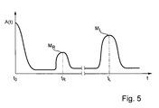
- Fig. 5 shows an example of an echo function A(t) determined with the arrangement shown in fig. 1 with reflector 13 inserted into the transmission lobe 15. It shows two distinct maxima.
- the microwave signal is transmitted at time to.
- the first maximum M R is caused by a reflection of the microwave signal on reflector 13 and occurs at a corresponding transit time t R needed to travel from the device 5 to the reflector 13 and to return to the device 5.
- the second maximum M L is caused by a reflection of the microwave signal on the surface of the medium 3 and occurs at a corresponding transit time t L needed to travel from the device 5 to the surface of the medium 1 and to return to the device 5.
- the transit time t R at which the first maximum M R occurs corresponds to the insertion height of the reflector 13 and the transit time t L at which the second maximum M L occurs corresponds to the level of the medium 1 inside the container 3.
- the reflector 13 Since the reflector 13 only covers a fraction of the cross section of the transmission lobe 15 at its insertion height, only a fraction of the transmitted microwave signal is reflected at the reflector 13, whereas the main part of the signal reaches the surface of the medium 1. Consequently it is possible to measure both the insertion height of the reflector 13 as well as the level of the medium 1 simultaneously. The ongoing level measurement does not need to be interrupted in order to test proper operation and/or measurement accuracy of the device 5.
- the electronic 45 determines the level of the product based on the transit time t L needed for the microwave signal to travel to the surface of the medium 1 and of its echo signal to return to the device 5. In addition it determines the transit time t R needed for the microwave signal to travel to the reflector 13 and of its echo signal to return to the device 5. The later transit time t R is then used to test the level measurement device 5, in particular its proper operation and its measurement accuracy. The capability of the device 5 to measure this time of flight t R proves that the device 5 functions properly. A measured insertion height is calculated based on the measured transit time t R . Measurement accuracy of the device 5 is then determined by comparing the measured insertion height of the reflector 13 with the known predetermined insertion height, at which the reflector 13 is actually inserted.
- the level measurement arrangement according to the invention can for example be operated by permanently inserting the reflector 13 into the transmission lobe 15 of the transmitted microwave signals at a predetermined insertion height.
- the insertion height can be permanently stored in a memory of the electronic 45 upon installation of the arrangement and proper operation and/or measurement accuracy of the measurement device 45 can be continuously monitored by measuring the insertion height of the reflector 13 with the measurement device 5 and comparing the measured insertion height with the predetermined insertion height of the reflector 13.
- the device 5 permanently performs self tests. It does so fully automatically without any intervention from operating personal.
- the self tests can be used to certify that the measurement accuracy lies within a predetermined range, and to set off an alarm or warning if it does not.
- measurement accuracy can be monitored and recorded as a function of operating hours or life time of the device 5. In case the accuracy decreases with the time, a prediction can be made, at what time during the life span of the device 5, it will exceed the predetermined measurement accuracy and replacement or repair of the device 5 can be timed based on this prediction.
- the measurement arrangement can be operated by consecutively installing the reflector 13 at predetermined different insertion heights. This allows not only to determine the measurement accuracy but also to determine the accuracy as a function of the adjustable distance between the reflector 13 and the device 5.
- information about the actual insertion height needs to be transferred to electronic 45 either manually or automatically, e.g. via a control that sets the insertion height via the positioning device 27, e.g. the actuator or the motor, or the hydraulic system 31.
- This control can be an integral part of the electronic 45 which is connected to the positioning device 27 or the hydraulic system 31 respectively.
- the reflector 13 needs to be located above the medium 1. For this reason reflectors with a fixed insertion height can only be located above the highest possible level inside the container 3. With the described holders 21, 29, 33 which allow the insertion height to be adjusted, it is possible to perform tests at insertion heights below this highest level, as long as it located above the level of the medium currently present in the container 3. This can be easily assured by the arrangement according to the invention by simply measuring the level of the medium 1 and adjusting the adjustable insertion height accordingly such that the reflector 13 is always located well above the previously measured level of the medium 1. This makes it possible to monitor the measurement accuracy of the device 5 not only in designated test areas well above the highest possible level but also in areas in which later level measurements are required. If the container 3 is emptied during the normal ongoing production process, it is even possible to test the measurement accuracy of the device 5 over the entire measurement range reaching from the bottom of the container 3 up to the highest possible level.
- Fig. 6 shows another embodiment of an arrangement according to the invention. Due to the similarities to the previously described embodiment only the differences are described in detail below.
- two reflectors are foreseen, the previously described reflector 13 and an additional reflector 49.
- the two reflector 13, 49 are mounted onto the mounting means, here holder 21, attached to the process connector 7. They are located at two different insertion heights above the medium 1 inside the container 3.
- Each reflector 13, 49 is inserted into the transmission lobe 15 of the transmitted microwave signals and covers a fraction of a cross-section 17, 51 of the transmission lobe 15 of the transmitted microwave signals at its insertion height.
- the reflectors 13, 49 and the cross sections 17, 51 covered by them are positioned and dimensioned such that both reflectors 13, 49 are at least partially exposed to a fraction of the transmitted microwave signals.
- reflector 13 and additional reflector 49 are both disc shaped and have a thin long rectangular cross section.
- the additional reflector 49 is positioned above the reflector 13 and extends from the holder 21 into the middle of the transmission lobe 15.
- Reflector 13 has the same shape and runs parallel to the additional reflector 49 across the entire width of the transmission lobe 15 at its insertion height.
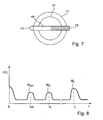
- Fig. 7 shows the reflector 13, the additional reflector 49 and their partially overlapping positions within the cross section 17 of the transmission lobe 15 at the insertion height of reflector 13 and within the cross section 51 of the transmission lobe 15 at the insertion height of the additional reflector 49 as seen from above.
- various other designs and reflector positions can be chosen, as long as both the reflector 13 and the additional reflector 49 are exposed to a fraction of the transmitted microwave signal.
- Fig. 8 shows a corresponding echo function A(t) derived with the measurement arrangement shown in fig. 6 . It shows three distinct maxima, a first maximum M AR occurring at a transit time t AR corresponding to the distance between the device 5 and the additional reflector 49, the second maximum M R occurring at a transit time t R corresponding to the distance between the device 5 and the reflector 13, and the third maximum M L occurring at a transit time t L corresponding to the distance between the device 5 and the surface of the medium 1.
- This propagation velocity v is then used for determining the level of the medium 1 inside the container 3 based on the measured transit time t L needed for the microwave signal to travel from the device 5 to the surface of the medium and for its echo signal to return to the device 5.
- this arrangement not only allows to monitor the measurement accuracy of the measurement device 5 but also to calibrate it by determining the propagation velocity v used to calculate the level based on the transit time.
- This calibration method is especially advantages in applications, wherein the propagation velocity v of the microwave signals may vary over time. This is for example the case in applications, wherein a pressure, a temperature and a composition of a gas, which fills the interior of the container 3 above the medium 1 may vary in accordance with an ongoing production process. In this case regular or repeated re-calibration ensures a high measurement accuracy.
Abstract
Description
- The present invention concerns an arrangement for measurement of a level of a medium in a container, comprising a level measurement device comprising a process connector for mounting said device on an opening of the container, an antenna for transmitting signals into said container and for receiving echo signals resulting from reflections of the transmitted signals inside the container, and a measurement electronic, for determining the level of the medium based on a measurement of a transit time needed for the signal to travel to the surface of the medium and of its echo to return to the device.
- In many branches of industry products are stored or processed in containers, e.g. tanks, vessels or others. It has become a very important field of measurement technology to determine a level of a medium inside a container. Level measurements are valuable means in process control as well as in process automation.
- One method of level measurement used today involves the use of short electromagnetic waves, in particular microwaves. Microwave level measurement devices transmit microwave signals through an opening in the container toward the surface of the medium inside and receive echo signals of the transmitted microwaves. From the received echo signals an echo function representing echo amplitude as a function of the distance or time is formed for each measurement. A transit time of a microwave signal to travel from the device to the surface and of its echo to return to the device is determined based on the echo function. The distance between the device and the surface is then determined based on the transit time.
- Various microwave level measuring techniques are known which permit short distances to be measured by means of reflected waves. The most frequently used systems are pulse radar and frequency-modulated continuous wave radar (FMCW-Radar).
- Pulse radar level measurement devices periodically send short microwave pulses. The transit time between the transmission of the microwave pulse and the reception of its echo is measured and the level is determined based on the transit time.
- FMCW radar level measurement devices transmit a continuous microwave signal, which is periodically linearly frequency modulated. The frequency of the received echo signal differs from the frequency of the transmitted signal by an amount, which depends on the transit time between the emission and the reception of the corresponding echo.
- The microwave signals are transmitted and received via antennas. Commonly used antennas are for example horn antennas comprising a metal horn, rod antennas comprising a dielectric rod or planar antennas using microstrip line technology, as for example described in
US-B1 6,266,022 . - Other measurement device are on the marked for measurement of a level of a medium inside a container based on a measurement of a transit time needed for a signal to travel from the device to the surface of the medium and of its echo signal, caused by a reflection of the transmitted signal on the surface, to return to the device. These devices are for example ultrasonic level measurement devices transmitting and receiving ultrasonic signals, or optical measurement devices transmitting and receiving optical signals.
- In many branches of industry, in particular in the oil and gas industry, safety, reliability and/or measurement accuracy of measurement devices is very important. To this extend it is necessary to ensure, that the devices operate properly and that the accuracy of their measurement results lies within a predefined range at all times. Safety requirements frequently require that proper operation and measurement accuracy of such measurement devices are tested regularly.
- Regular tests can for example be performed on specially designed test sites. This requires for the measurement device to be transferred from the measurement site onto the test site.
- Alternatively, proper operation and accuracy of the measurement can for example be tested, by raising the level of the medium inside the container on the measurement site to a predefined test level. The level measurement device then measures this level and the measurement result is compared to the known predefined test level. In order to raise the level to the predefined test level, the ongoing production process needs to be interrupted and the predefined test level needs to be determined by another measurement, independently of the measurement device to be tested.
- In
US 2005/0264440 A1 a test apparatus for a waveguide level sensing device is described. The waveguide level sensing device transmits electromagnetic pulses along a waveguide into a container and receives an echo signal of this pulse resulting from a reflection of the pulse on the surface of the level inside the waveguide. The test apparatus comprises a bridge, which can be moved into a test position, wherein the bridge bridges the waveguide during a test period. If the device functions properly, it will indicate a level corresponding to the level of the bride during test period. After each test period the bridge is moved into a storage position where the waveguide is not bridged. During the test period no level measurements can be performed. - All these testing methods have in common, that measurements of the level inside the container cannot be performed during the test period.
On the other hand, there is a need in industry, for continuous measurement of the level. This is especially important, e.g. in applications, where the level measurement is used for process control, e.g. in order to prevent an overflow. It is an object of the invention to provide a level measurement arrangement comprising a level measurement device for measuring a level of a medium inside a container based on a measurement of a transit time needed for a signal to travel from the device to the surface of the medium and of its echo signal, caused by a reflection of the transmitted signal on the surface, to return to the device, which can be tested during normal measurement operation. - To this end the invention comprises an arrangement for measurement of a level of a medium in a container, comprising:
- a level measurement device comprising:
- -- a process connector for mounting said device on an opening of the container,
- -- an antenna for transmitting signals into said container and for receiving echo signals resulting from reflections of the transmitted signals inside the container,
- an apparatus for testing proper operation and/or measurement accuracy of the level measurement device, comprising:
- -- a reflector,
- -- mounting means mounted onto the process connector for mounting the reflector at an insertion height inside the container above the medium at which the reflector is inserted into a transmission lobe of the transmitted signals and covers a fraction of a cross-section of the
transmission lobe of the transmitted signals, and - -- a test and measurement electronic,
- --- for determining the level of the medium based on a transit time needed for the signals to travel to the surface of the medium and for their echo signals to return to the device, and
- --- for testing the level measurement device based on a transit time needed for the signals to travel to the reflector and for their echo signals to return to the device.
- It further comprises an arrangement according to the invention, wherein
- the mounting means comprise an elongated holder extending through the process connector into the container,
- a length of a section of said holder extending into the container is adjustable,
- the reflector is mounted onto an end of the holder inside the container, and
- the insertion height at which the reflector is located inside the container is determined by the adjustable length of this section.
- It further comprises an arrangement according to the invention, wherein
- the mounting means comprise an elongated holder comprising a telescopic rod of adjustable length extending into the container,
- the reflector is mounted onto an end of the telescopic rod, and
- the adjustable length determines the insertion height of the reflector.
- It further comprises an arrangement according to the invention, wherein
- the mounting means comprise a foldable holder comprising:
- -- segments, which are interconnected by hinges to form a foldable rod, and
- -- a rod shaped end section which is permanently located inside the container,
- the end section is connected to a first end of the foldable rod,
- mounting means are foreseen for mounting the holder onto the process connector, comprising
- an opening through which a selectable number of the segments can be inserted through the process connector into the container,
- the segments which are located inside the container form a straight rod,
- the segments which are located outside the container are folded together,
- the reflector is mounted onto the end section, and
- the insertion height at which the reflector is inserted inside the container is determined by the selected number of the segments inserted into the container.
- According to a preferred embodiment, the reflector is a flat disc having a long thin rectangular cross section.
- According to a refinement of the invention,
- two reflectors are mounted on the mounting means at two different insertion heights above the medium inside the container,
- each reflector is inserted into said transmission lobe of the transmitted signals and covers a fraction of a cross-section of the transmission lobe of the transmitted signals at its insertion height, and
- both reflectors are exposed to a fraction of the transmitted signal.
- According to a preferred embodiment of the invention, the signals are microwave signals.
- The invention further comprises a method of operating an arrangement according to the invention, wherein
- the reflector is permanently inserted into the transmission lobe of the transmitted signals at a predetermined insertion height, and
- proper operation and/or measurement accuracy of the measurement device is continuously or regularly monitored by measuring the insertion height of the reflector with the measurement device and comparing the measured insertion height with the predetermined insertion height of the reflector.
- The invention further comprises an alternative method of operating an arrangement according to the invention, wherein
- the reflector is consecutively inserted into the transmission lobe of the transmitted signals at different predetermined insertion heights, and
- measurement accuracy of the measurement device is determined by measuring the respective insertion heights of the reflector with the measurement device and comparing the measured insertion heights with the corresponding different predetermined insertion heights of the reflector.
- The invention further comprises a further method of operating an arrangement according to the invention, wherein
- the insertion height of the reflector is adjustable,
- level is measured with the measurement device and
- the insertion height of the reflector is adjusted based on the level measured, such that the reflector is located above the previously measured level of the medium.
- The invention further comprises a method of calibrating the level measurement device of an arrangement according to the refinement of the invention, comprising the steps of
- measuring the transit times needed for the signals to travel from the device to each of the reflectors and their echo signals to return to the device,
- calculating a propagation velocity of the signals in the container above the medium based on the difference between the two measured transit times and the distance between the insertion heights of the two reflectors, and
- using the calculated propagation velocity for determining the level of the medium based on a measured transit time needed for the signal to travel from the device to the surface of the medium and for its echo signal to return to the device.
- It is an advantage of the invention, that the insertion height at which the reflector is inserted into the transmission lobe is adjustable. Measurement accuracy of the device can thus be tested and approved for various different distances between the device and the reflector.
- The invention and its advantages are explained in more detail using the figures of the drawing, in which four embodiments are shown. The same reference numerals refer to the same elements throughout the figures.
-
- Fig. 1 shows:
- a microwave level measurement arrangement according to the invention;
- Fig. 2 shows:
- the reflector of
fig. 1 and a cross-section of the transmission lobe at the insertion height of the reflector; - Fig. 3 shows:
- a holder for the reflector comprising a telescopic rod of adjustable length;
- Fig. 4 shows:
- a foldable holder for inserting the reflector at different predetermined insertion heights;
- Fig. 5 shows:
- an example of an echo function derived with the arrangement shown in
fig. 1 ; - Fig. 6 shows:
- a microwave level measurement arrangement according to the invention comprising two reflectors;
- Fig. 7 shows:
- the reflectors of
fig. 5 and their partially overlapping positions within the cross sections of the transmission lobe at their respective insertion height; and - Fig. 8 shows:
- an echo function derived with the measurement arrangement according to
fig. 6 . -
Fig. 1 shows a microwave level measurement arrangement for measurement of a level of a medium 1 in acontainer 3. It comprises alevel measurement device 5, which is mounted onto an opening on thecontainer 3 via aprocess connector 7. Themeasurement device 5 is for example a pulse radar measurement device or an FMCW level measurement device as described above. - Even though the invention is described in detail below using a microwave level measurement device it is not limited to arrangements comprising microwave level measurement devices. Instead of the microwave
level measurement device 5 other level measurement devices can be used in the arrangements according to the invention, as long as they are designed to measure level by measuring a transit time needed for a signal to travel from the device to the surface of the medium and of its corresponding echo signal, generated by a reflection of the transmitted signal on this surface, to return to the device. Such devices are for example ultrasonic level measurement devices transmitting and receiving ultrasonic signals, or optical measurement devices transmitting and receiving optical signals. - In the embodiment shown, the
process connector 7 is a flange, which is mounted onto a corresponding counter part 9 surrounding the opening of thecontainer 3. Themeasurement device 5 comprises anantenna 11 for transmitting microwave signals into thecontainer 3 and for receiving their echo signals resulting from reflections of the transmitted microwave signals inside thecontainer 3. Theantenna 11 is for example a horn antenna as shown infig. 1 . Alternatively other types of antennas known in the field can be used, designed to transmit microwave signals into free space and to receive their echo signals, e.g. rod antennas comprising a dielectric rod or planar antennas using microstrip line technology. - The arrangement further comprises an apparatus for testing the microwave
level measurement device 5, in particular for testing the proper operation and/or measurement accuracy of thedevice 5. - Central element of this apparatus is a
reflector 13 which is inserted into atransmission lobe 15 of the transmitted microwave signals at a predetermined preferably adjustable insertion height inside thecontainer 3. Thetransmission lobe 15 has the shape of a three dimensional cone as indicated infig. 1 by a dashed line. Thereflector 13 is dimensioned such, that it covers a fraction of across-section 17 of thetransmission lobe 15 at its insertion height. -
Fig. 2 shows thecross-section 17 of thetransmission lobe 15 at the insertion height shown infig. 1 and an exemplary embodiment ofreflector 13. Thecross-section 17 of thetransmission lobe 15 is circular and thereflector 13 is a flat disc, having a long thin rectangular cross section. - Mounting means are foreseen for mounting the
reflector 13 inside thecontainer 3 above themedium 1. The mounting means are mounted onto theprocess connector 7 viaconnector 19. This has the advantage, that thereflector 13 can be mounted together with themeasurement device 5 and no separate openings need to be provided on thecontainer 3. In the embodiment shown infig. 1 , the mounting means comprise an elongated rod shapedholder 21, which extends through theprocess connector 7 into thecontainer 3, such that asection 23 of theholder 21 is located inside and asection 25 of theholder 21 is located outside thecontainer 3. Thereflector 13 is mounted on a bottom end of theholder 21 inside thecontainer 3 and extends perpendicular to a longitudinal axis of theholder 21. The insertion height of thereflector 13 is given by the length of thesection 23 of theholder 21 extending into thecontainer 3. Preferablyconnector 19 is a releasable connector which allows for the length of thesection 23 inside thecontainer 3 to be adjusted by pushing theholder 21 further into thecontainer 3 or by pulling it further out of thecontainer 3. By adjusting the length of thesection 23 of theholder 21 inside thecontainer 3 and fixing theholder 21 in a chosen or predetermined position via theconnector 19, the insertion height of thereflector 13 can be adjusted. Theholder 21 can be positioned and fixed manually or by apositioning device 27, e.g. an actuator or motor attached to theholder 21 including theconnector 19. - Instead of the holder 21 a
holder 29 can be used comprising a telescopic rod of adjustable length, as shown infig. 3 . The telescopic rod is e.g. entirely located inside thecontainer 3 and mounted onto theprocess connector 7. Length adjustment can for example be performed by ahydraulic system 31 mounted outside thecontainer 3 on theprocess connector 7 and connected to the telescopic rod on the inside, via an opening in theprocess connector 7. -
Fig. 4 shows a further embodiment of mounting means for mounting thereflector 13 at different predetermined insertion heights inside thecontainer 3. Here mounting means comprise afoldable holder 33 for inserting thereflector 13 at different predetermined insertion heights. Theholder 33 consists of rod shaped segments 35, heresegments hinges 37 to form a foldable rod, and a rod shapedend section 39. Theend section 39 is permanently located inside thecontainer 3 and connected to a first end of the foldable rod, e.g. by an additional hinge. - Mounting means 41, are foreseen for mounting the
holder 33 onto an opening extending through theprocess connector 7. The mounting means 41 comprise an opening through which a selectable number of the segments 35 can be inserted through theprocess connector 7 into thecontainer 3. Thesegments 35e which are inserted into thecontainer 3 form a straight rod, extending in a straight line with theend section 39 connected thereto. Preferably hollowcylindrical caps 43 are foreseen on theholder 33 near eachhinge 37, which slide over therespective hinge 37 due to gravity when thehinge 37 is straightened and brought into a vertical position for insertion. Thecaps 43 then prevent any further movement of therespective hinge 37 after its insertion into thecontainer 3. The remainingsegments container 3 are folded together. - The
reflector 13 is mounted onto theend section 39. Thus the insertion height at which thereflector 13 is inserted inside thecontainer 3 is determined by the selected number of thesegments 35e inserted into thecontainer 3. - The arrangement further comprises a test and measurement electronic 45. The electronic 45 is for example located inside a
housing 47 of thelevel measurement device 5 attached to theprocess connector 7 and is connected to theantenna 11 of thedevice 5. The electronic 45 comprises a microwave signal generator for generating the microwave signals and supplies them to theantenna 11 for transmission. Transmitted signals are reflected at reflective surfaces inside thecontainer 3 and their respective echo signals are received by theantenna 11 and supplied to the electronic 45. A transit time t needed for a microwave signal to travel to a reflective surface and of its echo signal to return to thedevice 5 is proportional to the distance between the reflective surface and thedevice 5. Given the propagation velocity of microwave signals inside thecontainer 3, distance can be calculated from transit time t and vice versa. Based on the echo signals received by theantenna 11, the electronic 45 e.g. determines an echo function representing an echo amplitude A(t) of the echo signal as a function of the distance or the transit time t. Distance and transit time t are equivalent. -
Fig. 5 shows an example of an echo function A(t) determined with the arrangement shown infig. 1 withreflector 13 inserted into thetransmission lobe 15. It shows two distinct maxima. The microwave signal is transmitted at time to. The first maximum MR is caused by a reflection of the microwave signal onreflector 13 and occurs at a corresponding transit time tR needed to travel from thedevice 5 to thereflector 13 and to return to thedevice 5. The second maximum ML is caused by a reflection of the microwave signal on the surface of themedium 3 and occurs at a corresponding transit time tL needed to travel from thedevice 5 to the surface of themedium 1 and to return to thedevice 5. The transit time tR at which the first maximum MR occurs corresponds to the insertion height of thereflector 13 and the transit time tL at which the second maximum ML occurs corresponds to the level of themedium 1 inside thecontainer 3. - Since the
reflector 13 only covers a fraction of the cross section of thetransmission lobe 15 at its insertion height, only a fraction of the transmitted microwave signal is reflected at thereflector 13, whereas the main part of the signal reaches the surface of themedium 1. Consequently it is possible to measure both the insertion height of thereflector 13 as well as the level of the medium 1 simultaneously. The ongoing level measurement does not need to be interrupted in order to test proper operation and/or measurement accuracy of thedevice 5. - The electronic 45 determines the level of the product based on the transit time tL needed for the microwave signal to travel to the surface of the
medium 1 and of its echo signal to return to thedevice 5. In addition it determines the transit time tR needed for the microwave signal to travel to thereflector 13 and of its echo signal to return to thedevice 5. The later transit time tR is then used to test thelevel measurement device 5, in particular its proper operation and its measurement accuracy. The capability of thedevice 5 to measure this time of flight tR proves that thedevice 5 functions properly. A measured insertion height is calculated based on the measured transit time tR. Measurement accuracy of thedevice 5 is then determined by comparing the measured insertion height of thereflector 13 with the known predetermined insertion height, at which thereflector 13 is actually inserted. - The level measurement arrangement according to the invention can for example be operated by permanently inserting the
reflector 13 into thetransmission lobe 15 of the transmitted microwave signals at a predetermined insertion height. In this case the insertion height can be permanently stored in a memory of the electronic 45 upon installation of the arrangement and proper operation and/or measurement accuracy of themeasurement device 45 can be continuously monitored by measuring the insertion height of thereflector 13 with themeasurement device 5 and comparing the measured insertion height with the predetermined insertion height of thereflector 13. Thus thedevice 5 permanently performs self tests. It does so fully automatically without any intervention from operating personal. The self tests can be used to certify that the measurement accuracy lies within a predetermined range, and to set off an alarm or warning if it does not. In addition measurement accuracy can be monitored and recorded as a function of operating hours or life time of thedevice 5. In case the accuracy decreases with the time, a prediction can be made, at what time during the life span of thedevice 5, it will exceed the predetermined measurement accuracy and replacement or repair of thedevice 5 can be timed based on this prediction. - Alternatively, the measurement arrangement can be operated by consecutively installing the
reflector 13 at predetermined different insertion heights. This allows not only to determine the measurement accuracy but also to determine the accuracy as a function of the adjustable distance between thereflector 13 and thedevice 5. In this case information about the actual insertion height needs to be transferred to electronic 45 either manually or automatically, e.g. via a control that sets the insertion height via thepositioning device 27, e.g. the actuator or the motor, or thehydraulic system 31. This control can be an integral part of the electronic 45 which is connected to thepositioning device 27 or thehydraulic system 31 respectively. - During tests, the
reflector 13 needs to be located above themedium 1. For this reason reflectors with a fixed insertion height can only be located above the highest possible level inside thecontainer 3. With the describedholders container 3. This can be easily assured by the arrangement according to the invention by simply measuring the level of themedium 1 and adjusting the adjustable insertion height accordingly such that thereflector 13 is always located well above the previously measured level of themedium 1. This makes it possible to monitor the measurement accuracy of thedevice 5 not only in designated test areas well above the highest possible level but also in areas in which later level measurements are required. If thecontainer 3 is emptied during the normal ongoing production process, it is even possible to test the measurement accuracy of thedevice 5 over the entire measurement range reaching from the bottom of thecontainer 3 up to the highest possible level. -
Fig. 6 shows another embodiment of an arrangement according to the invention. Due to the similarities to the previously described embodiment only the differences are described in detail below. In this embodiment two reflectors are foreseen, the previously describedreflector 13 and anadditional reflector 49. The tworeflector holder 21, attached to theprocess connector 7. They are located at two different insertion heights above themedium 1 inside thecontainer 3. - Each
reflector transmission lobe 15 of the transmitted microwave signals and covers a fraction of across-section transmission lobe 15 of the transmitted microwave signals at its insertion height. Thereflectors cross sections reflectors - In the embodiment shown in
fig. 6 reflector 13 andadditional reflector 49 are both disc shaped and have a thin long rectangular cross section. Theadditional reflector 49 is positioned above thereflector 13 and extends from theholder 21 into the middle of thetransmission lobe 15.Reflector 13 has the same shape and runs parallel to theadditional reflector 49 across the entire width of thetransmission lobe 15 at its insertion height.Fig. 7 shows thereflector 13, theadditional reflector 49 and their partially overlapping positions within thecross section 17 of thetransmission lobe 15 at the insertion height ofreflector 13 and within thecross section 51 of thetransmission lobe 15 at the insertion height of theadditional reflector 49 as seen from above. Obviously various other designs and reflector positions can be chosen, as long as both thereflector 13 and theadditional reflector 49 are exposed to a fraction of the transmitted microwave signal. -
Fig. 8 shows a corresponding echo function A(t) derived with the measurement arrangement shown infig. 6 . It shows three distinct maxima, a first maximum MAR occurring at a transit time tAR corresponding to the distance between thedevice 5 and theadditional reflector 49, the second maximum MR occurring at a transit time tR corresponding to the distance between thedevice 5 and thereflector 13, and the third maximum ML occurring at a transit time tL corresponding to the distance between thedevice 5 and the surface of themedium 1. - Permanently inserting two
reflectors device 5 at two different heights inside thecontainer 3. - In addition the two
reflectors device 5 to calibrate itself. Calibration of thedevice 5 is performed by measuring the transit times tAR, tR needed for the microwave signals to travel from thedevice 5 to each of thereflectors device 5. Thedevice 5 then calculates the propagation velocity v of the microwave signals inside thecontainer 3 above the medium 1 based on these transition times tAR, tR and the known distance between the two insertion heights of the tworeflectors 
wherein - D
- is the distance between the insertion height of the two reflectors,
- tR-tAR
- is the difference between the two measured times of flight.
- This propagation velocity v is then used for determining the level of the
medium 1 inside thecontainer 3 based on the measured transit time tL needed for the microwave signal to travel from thedevice 5 to the surface of the medium and for its echo signal to return to thedevice 5. - Thus this arrangement not only allows to monitor the measurement accuracy of the
measurement device 5 but also to calibrate it by determining the propagation velocity v used to calculate the level based on the transit time. - This calibration method is especially advantages in applications, wherein the propagation velocity v of the microwave signals may vary over time. This is for example the case in applications, wherein a pressure, a temperature and a composition of a gas, which fills the interior of the
container 3 above themedium 1 may vary in accordance with an ongoing production process. In this case regular or repeated re-calibration ensures a high measurement accuracy. - 1
- medium
- 3
- container
- 5
- level measurement device
- 7
- process connector
- 9
- counter part for process connector
- 11
- antenna
- 13
- reflector
- 15
- transmission lobe
- 17
- cross-section of the transmission lobe at the insertion height of the reflector
- 19
- connector
- 21
- rod shaped holder
- 23
- section of holder inside the container
- 25
- section of holder outside the container
- 27
- positioning device
- 29
- holder comprising a telescopic rod
- 31
- hydraulic system
- 33
- holder
- 35
- segment
- 37
- hinges
- 39
- end section
- 41
- mounting means
- 43
- cap
- 45
- test and measurement electronic
- 47
- housing
- 49
- additional reflector
- 51
- cross-section of the transmission lobe at the insertion height of the additional reflector
Claims (11)
- Arrangement for measurement of a level of a medium (1) in a container (3), comprising:- a level measurement device (5) comprising:-- a process connector (7) for mounting said device on an opening of the container (3),-- an antenna (11) for transmitting signals into said container (3) and for receiving echo signals resulting from reflections of the transmitted signals inside the container (3),- an apparatus for testing proper operation and/or measurement accuracy of the level measurement device (5), comprising:-- a reflector (13, 49),-- mounting means mounted onto the process connector (7) for mounting the reflector (13, 49) at an insertion height inside the container (3) above the medium (1) at which the reflector (13, 49) is inserted into a transmission lobe (15) of the transmitted signals and covers a fraction of a cross-section (17, 51) of the transmission lobe (15) of the transmitted signals, and- a test and measurement electronic (45),-- for determining the level of the medium (1) based on a transit time (tL) needed for the signals to travel to the surface of the medium (1) and for their echo signals to return to the device (5), and-- for testing the level measurement device (5) based on a transit time (tR, tAR) needed for the signals to travel to the reflector (13, 49) and for their echo signals to return to the device (5).
- Arrangement according to claim 1, wherein- the mounting means comprise an elongated holder (21) extending through the process connector (7) into the container (3),- a length of a section (23) of said holder (21) extending into the container (3) is adjustable,- the reflector (13) is mounted onto an end of the holder (21) inside the container (3), and- the insertion height at which the reflector (13) is located inside the container (3) is determined by the adjustable length of this section (23).
- Arrangement according to claim 1, wherein- the mounting means comprise an elongated holder (29) comprising a telescopic rod of adjustable length extending into the container (3),- the reflector (13) is mounted onto an end of the telescopic rod, and- the adjustable length determines the insertion height of the reflector (13).
- Arrangement according to claim 1, wherein- the mounting means comprise a foldable holder (33) comprising:-- segments (35), which are interconnected by hinges (37) to form a foldable rod, and-- a rod shaped end section (39) which is permanently located inside the container (3),- the end section (39) is connected to a first end of the foldable rod,- mounting means (41) are foreseen for mounting the holder (33) onto the process connector (7), comprising:-- an opening through which a selectable number of the segments (35) can be inserted through the process connector (7) into the container (3),- the segments (35e) which are located inside the container (3) form a straight rod,- the segments (35a, 35b, 35c, 35d) which are located outside the container (3) are folded together,- the reflector (13) is mounted onto the end section (39), and- the insertion height at which the reflector (13) is inserted inside the container (3) is determined by the selected number of the segments (35e) inserted into the container (3).
- Arrangement according to claim 1, wherein
the reflector (13, 49) is a flat disc having a thin long rectangular cross section. - Arrangement according to claim 1, wherein- two reflectors (13, 49) are mounted on the mounting means at two different insertion heights above the medium (1) inside the container (3),- each reflector (13, 49) is inserted into the transmission lobe (15) of the transmitted signals and covers a fraction of a cross-section (17, 51) of the transmission lobe (15) of the transmitted signals at its insertion height, and- both reflectors (13, 49) are exposed to a fraction of the transmitted signal.
- Arrangement according to one of the previous claims, wherein
the signals are microwave signals. - Method of operating an arrangement according to claim 1, wherein- the reflector (13, 49) is permanently inserted into the transmission lobe (15) of the transmitted signals at a predetermined insertion height, and- proper operation and/or measurement accuracy of the measurement device is continuously or regularly monitored by measuring the insertion height of the reflector (13, 49) with the measurement device (5) and comparing the measured insertion height with the predetermined insertion height of the reflector (13, 49).
- Method of operating an arrangement according to claim 1, wherein- the reflector (13) is consecutively inserted into the transmission lobe (15) of the transmitted signals at different predetermined insertion heights, and- measurement accuracy of the measurement device (5) is determined at the different insertion heights by measuring the respective insertion heights of the reflector (13) with the measurement device (5) and comparing the measured insertion heights with the corresponding predetermined different insertion height of the reflector (13).
- Method of operating an arrangement according to claim 1, wherein- the insertion height of the reflector (13) is adjustable,- level is measured with the measurement device (5) and- the insertion height of the reflector (13) is adjusted based on the level measured, such that the reflector (13) is located above the previously measured level of the medium (1).
- Method of calibrating the level measurement device of an arrangement according to claim 6, comprising the steps of:- measuring the transit times (tAR, tR) needed for the signals to travel from the device (5) to each of the reflectors (13, 49) and for their echo signals to return to the device (5),- calculating a propagation velocity (v) of the signals in the container (3) above the medium (1) based on the difference between the to measured transit times (tAR, tR) and the distance (D) between the insertion heights of the two reflectors (13, 49),- using the calculated propagation velocity (v) for determining the level of the medium (1) based on a measured transit time (tL) needed for the signal to travel from the device (5) to the surface of the medium (1) and for its echo to return to the device (5).
Priority Applications (1)
| Application Number | Priority Date | Filing Date | Title |
|---|---|---|---|
| EP08172559A EP2199763B1 (en) | 2008-12-22 | 2008-12-22 | Level Measurement Arrangement |
Applications Claiming Priority (1)
| Application Number | Priority Date | Filing Date | Title |
|---|---|---|---|
| EP08172559A EP2199763B1 (en) | 2008-12-22 | 2008-12-22 | Level Measurement Arrangement |
Publications (2)
| Publication Number | Publication Date |
|---|---|
| EP2199763A1 true EP2199763A1 (en) | 2010-06-23 |
| EP2199763B1 EP2199763B1 (en) | 2012-06-27 |
Family
ID=40351589
Family Applications (1)
| Application Number | Title | Priority Date | Filing Date |
|---|---|---|---|
| EP08172559A Not-in-force EP2199763B1 (en) | 2008-12-22 | 2008-12-22 | Level Measurement Arrangement |
Country Status (1)
| Country | Link |
|---|---|
| EP (1) | EP2199763B1 (en) |
Cited By (12)
| Publication number | Priority date | Publication date | Assignee | Title |
|---|---|---|---|---|
| WO2010096451A1 (en) * | 2009-02-17 | 2010-08-26 | Gk Tech Star, Llc | Level gauge with positive level verifier |
| WO2012031981A1 (en) * | 2010-09-07 | 2012-03-15 | Rosemount Tank Radar Ab | Radar level gauge system with operation monitoring functionality |
| DE102012104926A1 (en) * | 2012-06-06 | 2013-12-12 | Endress + Hauser Gmbh + Co. Kg | Method for calibrating distance measuring device e.g. radar level gauge for determining liquid level in container, involves measuring distance between distance measuring device and object with respect to reflected measurement signal |
| DE102013214324A1 (en) * | 2013-07-22 | 2015-01-22 | Vega Grieshaber Kg | Radar level gauge with a safety device |
| US9322699B2 (en) | 2013-07-03 | 2016-04-26 | Rosemount Tank Radar Ab | Radar level gauge and methods of testing radar level gauge and system |
| US9325077B2 (en) | 2013-11-12 | 2016-04-26 | Rosemount Tank Radar Ab | Radar level gauge system and reflector arrangement |
| EP3023754A3 (en) * | 2014-10-14 | 2016-06-22 | Rosemount Tank Radar AB | Radar level gauge with foldable probe |
| CN105717497A (en) * | 2014-12-17 | 2016-06-29 | 恩德莱斯和豪瑟尔两合公司 | System for calibrating a distance measuring device |
| DE102017106045A1 (en) * | 2017-03-21 | 2018-09-27 | Vega Grieshaber Kg | Procedure for calibrating a level gauge and level gauge |
| WO2020119879A1 (en) * | 2018-12-10 | 2020-06-18 | Abb Schweiz Ag | Radar sensor and robot using the same |
| DE102021103543A1 (en) | 2021-02-16 | 2022-08-18 | Endress+Hauser SE+Co. KG | Angle-resolving level gauge |
| DE102022120418A1 (en) | 2022-08-12 | 2024-02-15 | Vega Grieshaber Kg | Device and method for calibrating a level measuring device |
Families Citing this family (2)
| Publication number | Priority date | Publication date | Assignee | Title |
|---|---|---|---|---|
| CN103292874B (en) * | 2013-05-30 | 2015-06-24 | 中国计量学院 | Method and device for online verification and realtime self-calibration of radar liquid level meter |
| CN106643979A (en) * | 2016-12-23 | 2017-05-10 | 重庆川仪自动化股份有限公司 | Automatic compensation method and device for guided wave radar level meter measured value |
Citations (4)
| Publication number | Priority date | Publication date | Assignee | Title |
|---|---|---|---|---|
| US4210969A (en) | 1978-03-13 | 1980-07-01 | The Stoneleigh Trust | Sonic ranging systems to eliminate errors due to variations in the sound velocity in the medium |
| US20050264440A1 (en) | 2004-05-25 | 2005-12-01 | Rosemount Inc. | Test apparatus for a waveguide sensing level in a container |
| EP1785701A1 (en) * | 2005-11-11 | 2007-05-16 | Siemens Milltronics Process Instruments Inc. | Apparatus and method for determining a temperature of a volume of gas |
| GB2443533A (en) | 2006-10-30 | 2008-05-07 | Hymetrics Ltd | Distance sensor with moveable reference plate |
-
2008
- 2008-12-22 EP EP08172559A patent/EP2199763B1/en not_active Not-in-force
Patent Citations (4)
| Publication number | Priority date | Publication date | Assignee | Title |
|---|---|---|---|---|
| US4210969A (en) | 1978-03-13 | 1980-07-01 | The Stoneleigh Trust | Sonic ranging systems to eliminate errors due to variations in the sound velocity in the medium |
| US20050264440A1 (en) | 2004-05-25 | 2005-12-01 | Rosemount Inc. | Test apparatus for a waveguide sensing level in a container |
| EP1785701A1 (en) * | 2005-11-11 | 2007-05-16 | Siemens Milltronics Process Instruments Inc. | Apparatus and method for determining a temperature of a volume of gas |
| GB2443533A (en) | 2006-10-30 | 2008-05-07 | Hymetrics Ltd | Distance sensor with moveable reference plate |
Cited By (26)
| Publication number | Priority date | Publication date | Assignee | Title |
|---|---|---|---|---|
| WO2010096451A1 (en) * | 2009-02-17 | 2010-08-26 | Gk Tech Star, Llc | Level gauge with positive level verifier |
| US8830118B2 (en) | 2010-09-07 | 2014-09-09 | Rosemount Tank Radar Ab | Radar level gauge system with operation monitoring functionality |
| RU2602417C2 (en) * | 2010-09-07 | 2016-11-20 | Роузмаунт Танк Радар Аб | Radar level measurement system with the function of operation monitoring |
| WO2012031981A1 (en) * | 2010-09-07 | 2012-03-15 | Rosemount Tank Radar Ab | Radar level gauge system with operation monitoring functionality |
| CN103472439B (en) * | 2012-06-06 | 2016-01-20 | 恩德莱斯和豪瑟尔两合公司 | The method and system of calibrated distance measurement mechanism |
| DE102012104926A1 (en) * | 2012-06-06 | 2013-12-12 | Endress + Hauser Gmbh + Co. Kg | Method for calibrating distance measuring device e.g. radar level gauge for determining liquid level in container, involves measuring distance between distance measuring device and object with respect to reflected measurement signal |
| CN103472439A (en) * | 2012-06-06 | 2013-12-25 | 恩德莱斯和豪瑟尔两合公司 | Method and system for calibration distance measuring device |
| US9322699B2 (en) | 2013-07-03 | 2016-04-26 | Rosemount Tank Radar Ab | Radar level gauge and methods of testing radar level gauge and system |
| CN104330130A (en) * | 2013-07-22 | 2015-02-04 | Vega格里沙贝两合公司 | Radar-based fill level measurement device having a security device |
| EP2829852A3 (en) * | 2013-07-22 | 2015-04-29 | VEGA Grieshaber KG | Radar fill level measuring device with a safety device |
| CN104330130B (en) * | 2013-07-22 | 2019-05-07 | Vega格里沙贝两合公司 | With fool proof filling level radar measuring instrument |
| DE102013214324A1 (en) * | 2013-07-22 | 2015-01-22 | Vega Grieshaber Kg | Radar level gauge with a safety device |
| US9653802B2 (en) | 2013-07-22 | 2017-05-16 | Vega Grieshaber Kg | Radar-based fill level measurement device having a security device |
| US9958311B2 (en) | 2013-07-22 | 2018-05-01 | Vega Grieshaber Kg | Radar-based fill level measurement device having a security device |
| EP3069111B1 (en) * | 2013-11-12 | 2021-04-14 | Rosemount Tank Radar AB | Radar level gauge system and reflector arrangement |
| RU2663279C1 (en) * | 2013-11-12 | 2018-08-03 | Роузмаунт Танк Радар Аб | Radar level gauge system and reflector arrangement |
| US9325077B2 (en) | 2013-11-12 | 2016-04-26 | Rosemount Tank Radar Ab | Radar level gauge system and reflector arrangement |
| EP3023754A3 (en) * | 2014-10-14 | 2016-06-22 | Rosemount Tank Radar AB | Radar level gauge with foldable probe |
| US9638567B2 (en) | 2014-10-14 | 2017-05-02 | Rosemount Tank Radar Ab | Radar level gauge with foldable probe |
| CN105717497A (en) * | 2014-12-17 | 2016-06-29 | 恩德莱斯和豪瑟尔两合公司 | System for calibrating a distance measuring device |
| DE102017106045A1 (en) * | 2017-03-21 | 2018-09-27 | Vega Grieshaber Kg | Procedure for calibrating a level gauge and level gauge |
| DE102017106045B4 (en) | 2017-03-21 | 2024-03-07 | Vega Grieshaber Kg | Method for calibrating a level measuring device and arrangement of a level measuring device and a reflector for carrying out the method |
| WO2020119879A1 (en) * | 2018-12-10 | 2020-06-18 | Abb Schweiz Ag | Radar sensor and robot using the same |
| US11385329B2 (en) * | 2018-12-10 | 2022-07-12 | Abb Schweiz Ag | Radar sensor and robot using the same |
| DE102021103543A1 (en) | 2021-02-16 | 2022-08-18 | Endress+Hauser SE+Co. KG | Angle-resolving level gauge |
| DE102022120418A1 (en) | 2022-08-12 | 2024-02-15 | Vega Grieshaber Kg | Device and method for calibrating a level measuring device |
Also Published As
| Publication number | Publication date |
|---|---|
| EP2199763B1 (en) | 2012-06-27 |
Similar Documents
| Publication | Publication Date | Title |
|---|---|---|
| EP2199763B1 (en) | Level Measurement Arrangement | |
| CN101389935B (en) | Radar liquid level determination using stepped-frequency pulse | |
| EP2210071B1 (en) | System and method for filling level determination | |
| RU2664916C2 (en) | Radar level gauge, method of testing level gauge and level gauging system comprising said level gauge | |
| EP2277018B1 (en) | Radar level gauge system using a waveguiding structure with periodically arranged reference impedance transitions | |
| EP2614341B1 (en) | Radar level gauge system with operation monitoring functionality | |
| EP1770409B1 (en) | Time-of-flight-ranging system and method for calibrating such a system | |
| CA2188910C (en) | Method for calibration in level measurement | |
| US5847567A (en) | Microwave level gauge with remote transducer | |
| EP3126795B1 (en) | Self-diagnosing fmcw radar level gauge | |
| EP2490040B1 (en) | Single conductor probe gwr system with reduced end of nozzle reflection | |
| EP2026094B1 (en) | A time-of-flight radar calibration system | |
| US20020017131A1 (en) | Device for measuring the filling level of a filling material in a container | |
| KR101576438B1 (en) | method of measuring level of liquid errorless and radar level gauge system using the same | |
| RU2653578C1 (en) | Radar-location level gage for measuring volume of bulk product in tanks | |
| RU2652261C2 (en) | Radar level gauging with signal division | |
| EP3301412B1 (en) | Guided wave radar level gauge system with dual transmission line probes for dielectric constant compensation | |
| US20100000314A1 (en) | Arrangement for fill level measurement | |
| CN110554210B (en) | Method for measuring flow velocity of medium | |
| US10753783B2 (en) | Method for determining an inner diameter of a sounding tube by a fill-level measuring device | |
| EP3704451B1 (en) | Radar level gauge system and method for interface measurement | |
| EP3848720A1 (en) | Guided wave radar level gauge and method for controlling the guided wave radar level gauge | |
| EP3857183B1 (en) | System and method for determining level and density distribution | |
| EP4116678A1 (en) | Non-intrusive contactless filling level determination system and method | |
| US20230077375A1 (en) | Device, system and method for rodless guided microwave radiation |
Legal Events
| Date | Code | Title | Description |
|---|---|---|---|
| PUAI | Public reference made under article 153(3) epc to a published international application that has entered the european phase |
Free format text: ORIGINAL CODE: 0009012 |
|
| AK | Designated contracting states |
Kind code of ref document: A1 Designated state(s): AT BE BG CH CY CZ DE DK EE ES FI FR GB GR HR HU IE IS IT LI LT LU LV MC MT NL NO PL PT RO SE SI SK TR |
|
| AX | Request for extension of the european patent |
Extension state: AL BA MK RS |
|
| 17P | Request for examination filed |
Effective date: 20100925 |
|
| 17Q | First examination report despatched |
Effective date: 20101111 |
|
| AKX | Designation fees paid |
Designated state(s): AT BE BG CH CY CZ DE DK EE ES FI FR GB GR HR HU IE IS IT LI LT LU LV MC MT NL NO PL PT RO SE SI SK TR |
|
| GRAP | Despatch of communication of intention to grant a patent |
Free format text: ORIGINAL CODE: EPIDOSNIGR1 |
|
| GRAS | Grant fee paid |
Free format text: ORIGINAL CODE: EPIDOSNIGR3 |
|
| GRAA | (expected) grant |
Free format text: ORIGINAL CODE: 0009210 |
|
| AK | Designated contracting states |
Kind code of ref document: B1 Designated state(s): AT BE BG CH CY CZ DE DK EE ES FI FR GB GR HR HU IE IS IT LI LT LU LV MC MT NL NO PL PT RO SE SI SK TR |
|
| REG | Reference to a national code |
Ref country code: GB Ref legal event code: FG4D |
|
| REG | Reference to a national code |
Ref country code: CH Ref legal event code: EP |
|
| REG | Reference to a national code |
Ref country code: AT Ref legal event code: REF Ref document number: 564473 Country of ref document: AT Kind code of ref document: T Effective date: 20120715 |
|
| REG | Reference to a national code |
Ref country code: IE Ref legal event code: FG4D |
|
| REG | Reference to a national code |
Ref country code: DE Ref legal event code: R096 Ref document number: 602008016708 Country of ref document: DE Effective date: 20120823 |
|
| PG25 | Lapsed in a contracting state [announced via postgrant information from national office to epo] |
Ref country code: LT Free format text: LAPSE BECAUSE OF FAILURE TO SUBMIT A TRANSLATION OF THE DESCRIPTION OR TO PAY THE FEE WITHIN THE PRESCRIBED TIME-LIMIT Effective date: 20120627 Ref country code: FI Free format text: LAPSE BECAUSE OF FAILURE TO SUBMIT A TRANSLATION OF THE DESCRIPTION OR TO PAY THE FEE WITHIN THE PRESCRIBED TIME-LIMIT Effective date: 20120627 Ref country code: SE Free format text: LAPSE BECAUSE OF FAILURE TO SUBMIT A TRANSLATION OF THE DESCRIPTION OR TO PAY THE FEE WITHIN THE PRESCRIBED TIME-LIMIT Effective date: 20120627 Ref country code: NO Free format text: LAPSE BECAUSE OF FAILURE TO SUBMIT A TRANSLATION OF THE DESCRIPTION OR TO PAY THE FEE WITHIN THE PRESCRIBED TIME-LIMIT Effective date: 20120927 |
|
| REG | Reference to a national code |
Ref country code: NL Ref legal event code: VDEP Effective date: 20120627 |
|
| REG | Reference to a national code |
Ref country code: AT Ref legal event code: MK05 Ref document number: 564473 Country of ref document: AT Kind code of ref document: T Effective date: 20120627 |
|
| REG | Reference to a national code |
Ref country code: LT Ref legal event code: MG4D Effective date: 20120627 |
|
| PG25 | Lapsed in a contracting state [announced via postgrant information from national office to epo] |
Ref country code: SI Free format text: LAPSE BECAUSE OF FAILURE TO SUBMIT A TRANSLATION OF THE DESCRIPTION OR TO PAY THE FEE WITHIN THE PRESCRIBED TIME-LIMIT Effective date: 20120627 Ref country code: LV Free format text: LAPSE BECAUSE OF FAILURE TO SUBMIT A TRANSLATION OF THE DESCRIPTION OR TO PAY THE FEE WITHIN THE PRESCRIBED TIME-LIMIT Effective date: 20120627 Ref country code: GR Free format text: LAPSE BECAUSE OF FAILURE TO SUBMIT A TRANSLATION OF THE DESCRIPTION OR TO PAY THE FEE WITHIN THE PRESCRIBED TIME-LIMIT Effective date: 20120928 Ref country code: HR Free format text: LAPSE BECAUSE OF FAILURE TO SUBMIT A TRANSLATION OF THE DESCRIPTION OR TO PAY THE FEE WITHIN THE PRESCRIBED TIME-LIMIT Effective date: 20120627 |
|
| PG25 | Lapsed in a contracting state [announced via postgrant information from national office to epo] |
Ref country code: EE Free format text: LAPSE BECAUSE OF FAILURE TO SUBMIT A TRANSLATION OF THE DESCRIPTION OR TO PAY THE FEE WITHIN THE PRESCRIBED TIME-LIMIT Effective date: 20120627 Ref country code: IS Free format text: LAPSE BECAUSE OF FAILURE TO SUBMIT A TRANSLATION OF THE DESCRIPTION OR TO PAY THE FEE WITHIN THE PRESCRIBED TIME-LIMIT Effective date: 20121027 Ref country code: RO Free format text: LAPSE BECAUSE OF FAILURE TO SUBMIT A TRANSLATION OF THE DESCRIPTION OR TO PAY THE FEE WITHIN THE PRESCRIBED TIME-LIMIT Effective date: 20120627 Ref country code: BE Free format text: LAPSE BECAUSE OF FAILURE TO SUBMIT A TRANSLATION OF THE DESCRIPTION OR TO PAY THE FEE WITHIN THE PRESCRIBED TIME-LIMIT Effective date: 20120627 Ref country code: CY Free format text: LAPSE BECAUSE OF FAILURE TO SUBMIT A TRANSLATION OF THE DESCRIPTION OR TO PAY THE FEE WITHIN THE PRESCRIBED TIME-LIMIT Effective date: 20120627 Ref country code: CZ Free format text: LAPSE BECAUSE OF FAILURE TO SUBMIT A TRANSLATION OF THE DESCRIPTION OR TO PAY THE FEE WITHIN THE PRESCRIBED TIME-LIMIT Effective date: 20120627 Ref country code: SK Free format text: LAPSE BECAUSE OF FAILURE TO SUBMIT A TRANSLATION OF THE DESCRIPTION OR TO PAY THE FEE WITHIN THE PRESCRIBED TIME-LIMIT Effective date: 20120627 Ref country code: AT Free format text: LAPSE BECAUSE OF FAILURE TO SUBMIT A TRANSLATION OF THE DESCRIPTION OR TO PAY THE FEE WITHIN THE PRESCRIBED TIME-LIMIT Effective date: 20120627 |
|
| PG25 | Lapsed in a contracting state [announced via postgrant information from national office to epo] |
Ref country code: PL Free format text: LAPSE BECAUSE OF FAILURE TO SUBMIT A TRANSLATION OF THE DESCRIPTION OR TO PAY THE FEE WITHIN THE PRESCRIBED TIME-LIMIT Effective date: 20120627 Ref country code: IT Free format text: LAPSE BECAUSE OF FAILURE TO SUBMIT A TRANSLATION OF THE DESCRIPTION OR TO PAY THE FEE WITHIN THE PRESCRIBED TIME-LIMIT Effective date: 20120627 Ref country code: PT Free format text: LAPSE BECAUSE OF FAILURE TO SUBMIT A TRANSLATION OF THE DESCRIPTION OR TO PAY THE FEE WITHIN THE PRESCRIBED TIME-LIMIT Effective date: 20121029 |
|
| PG25 | Lapsed in a contracting state [announced via postgrant information from national office to epo] |
Ref country code: NL Free format text: LAPSE BECAUSE OF FAILURE TO SUBMIT A TRANSLATION OF THE DESCRIPTION OR TO PAY THE FEE WITHIN THE PRESCRIBED TIME-LIMIT Effective date: 20120627 |
|
| PG25 | Lapsed in a contracting state [announced via postgrant information from national office to epo] |
Ref country code: ES Free format text: LAPSE BECAUSE OF FAILURE TO SUBMIT A TRANSLATION OF THE DESCRIPTION OR TO PAY THE FEE WITHIN THE PRESCRIBED TIME-LIMIT Effective date: 20121008 Ref country code: DK Free format text: LAPSE BECAUSE OF FAILURE TO SUBMIT A TRANSLATION OF THE DESCRIPTION OR TO PAY THE FEE WITHIN THE PRESCRIBED TIME-LIMIT Effective date: 20120627 |
|
| PLBE | No opposition filed within time limit |
Free format text: ORIGINAL CODE: 0009261 |
|
| STAA | Information on the status of an ep patent application or granted ep patent |
Free format text: STATUS: NO OPPOSITION FILED WITHIN TIME LIMIT |
|
| 26N | No opposition filed |
Effective date: 20130328 |
|
| REG | Reference to a national code |
Ref country code: DE Ref legal event code: R097 Ref document number: 602008016708 Country of ref document: DE Effective date: 20130328 |
|
| PG25 | Lapsed in a contracting state [announced via postgrant information from national office to epo] |
Ref country code: BG Free format text: LAPSE BECAUSE OF FAILURE TO SUBMIT A TRANSLATION OF THE DESCRIPTION OR TO PAY THE FEE WITHIN THE PRESCRIBED TIME-LIMIT Effective date: 20120927 Ref country code: MC Free format text: LAPSE BECAUSE OF NON-PAYMENT OF DUE FEES Effective date: 20121231 |
|
| REG | Reference to a national code |
Ref country code: CH Ref legal event code: PL |
|
| GBPC | Gb: european patent ceased through non-payment of renewal fee |
Effective date: 20121222 |
|
| REG | Reference to a national code |
Ref country code: IE Ref legal event code: MM4A |
|
| REG | Reference to a national code |
Ref country code: FR Ref legal event code: ST Effective date: 20130830 |
|
| PG25 | Lapsed in a contracting state [announced via postgrant information from national office to epo] |
Ref country code: CH Free format text: LAPSE BECAUSE OF NON-PAYMENT OF DUE FEES Effective date: 20121231 Ref country code: IE Free format text: LAPSE BECAUSE OF NON-PAYMENT OF DUE FEES Effective date: 20121222 Ref country code: LI Free format text: LAPSE BECAUSE OF NON-PAYMENT OF DUE FEES Effective date: 20121231 |
|
| PG25 | Lapsed in a contracting state [announced via postgrant information from national office to epo] |
Ref country code: MT Free format text: LAPSE BECAUSE OF FAILURE TO SUBMIT A TRANSLATION OF THE DESCRIPTION OR TO PAY THE FEE WITHIN THE PRESCRIBED TIME-LIMIT Effective date: 20120627 Ref country code: FR Free format text: LAPSE BECAUSE OF NON-PAYMENT OF DUE FEES Effective date: 20130102 Ref country code: GB Free format text: LAPSE BECAUSE OF NON-PAYMENT OF DUE FEES Effective date: 20121222 |
|
| PG25 | Lapsed in a contracting state [announced via postgrant information from national office to epo] |
Ref country code: TR Free format text: LAPSE BECAUSE OF FAILURE TO SUBMIT A TRANSLATION OF THE DESCRIPTION OR TO PAY THE FEE WITHIN THE PRESCRIBED TIME-LIMIT Effective date: 20120627 |
|
| PG25 | Lapsed in a contracting state [announced via postgrant information from national office to epo] |
Ref country code: LU Free format text: LAPSE BECAUSE OF NON-PAYMENT OF DUE FEES Effective date: 20121222 |
|
| PG25 | Lapsed in a contracting state [announced via postgrant information from national office to epo] |
Ref country code: HU Free format text: LAPSE BECAUSE OF FAILURE TO SUBMIT A TRANSLATION OF THE DESCRIPTION OR TO PAY THE FEE WITHIN THE PRESCRIBED TIME-LIMIT Effective date: 20081222 |
|
| REG | Reference to a national code |
Ref country code: DE Ref legal event code: R081 Ref document number: 602008016708 Country of ref document: DE Owner name: ENDRESS+HAUSER SE+CO. KG, DE Free format text: FORMER OWNER: ENDRESS + HAUSER GMBH + CO. KG, 79689 MAULBURG, DE |
|
| PGFP | Annual fee paid to national office [announced via postgrant information from national office to epo] |
Ref country code: DE Payment date: 20211210 Year of fee payment: 14 |
|
| REG | Reference to a national code |
Ref country code: DE Ref legal event code: R119 Ref document number: 602008016708 Country of ref document: DE |
|
| PG25 | Lapsed in a contracting state [announced via postgrant information from national office to epo] |
Ref country code: DE Free format text: LAPSE BECAUSE OF NON-PAYMENT OF DUE FEES Effective date: 20230701 |