EP2199478A2 - Joining system for perforated boards - Google Patents
Joining system for perforated boards Download PDFInfo
- Publication number
- EP2199478A2 EP2199478A2 EP09178824A EP09178824A EP2199478A2 EP 2199478 A2 EP2199478 A2 EP 2199478A2 EP 09178824 A EP09178824 A EP 09178824A EP 09178824 A EP09178824 A EP 09178824A EP 2199478 A2 EP2199478 A2 EP 2199478A2
- Authority
- EP
- European Patent Office
- Prior art keywords
- perforated plates
- adjacent
- distance
- joint system
- perforated
- Prior art date
- Legal status (The legal status is an assumption and is not a legal conclusion. Google has not performed a legal analysis and makes no representation as to the accuracy of the status listed.)
- Withdrawn
Links
- 125000006850 spacer group Chemical group 0.000 claims description 7
- 210000002105 tongue Anatomy 0.000 claims 1
- 229910052602 gypsum Inorganic materials 0.000 abstract description 5
- 239000010440 gypsum Substances 0.000 abstract description 5
- 238000010276 construction Methods 0.000 abstract description 3
- 230000000007 visual effect Effects 0.000 abstract description 3
- 238000000034 method Methods 0.000 description 14
- 239000000945 filler Substances 0.000 description 12
- 239000002131 composite material Substances 0.000 description 8
- 239000000853 adhesive Substances 0.000 description 6
- 230000001070 adhesive effect Effects 0.000 description 6
- 238000004026 adhesive bonding Methods 0.000 description 4
- 239000000463 material Substances 0.000 description 4
- 230000007704 transition Effects 0.000 description 3
- 230000018044 dehydration Effects 0.000 description 2
- 238000006297 dehydration reaction Methods 0.000 description 2
- 238000004519 manufacturing process Methods 0.000 description 2
- 238000007711 solidification Methods 0.000 description 2
- 230000008023 solidification Effects 0.000 description 2
- 238000005516 engineering process Methods 0.000 description 1
- 230000002349 favourable effect Effects 0.000 description 1
- 239000000203 mixture Substances 0.000 description 1
- 230000003287 optical effect Effects 0.000 description 1
- 238000012805 post-processing Methods 0.000 description 1
- IHQKEDIOMGYHEB-UHFFFAOYSA-M sodium dimethylarsinate Chemical class [Na+].C[As](C)([O-])=O IHQKEDIOMGYHEB-UHFFFAOYSA-M 0.000 description 1
Images

Classifications
-
- E—FIXED CONSTRUCTIONS
- E04—BUILDING
- E04B—GENERAL BUILDING CONSTRUCTIONS; WALLS, e.g. PARTITIONS; ROOFS; FLOORS; CEILINGS; INSULATION OR OTHER PROTECTION OF BUILDINGS
- E04B1/00—Constructions in general; Structures which are not restricted either to walls, e.g. partitions, or floors or ceilings or roofs
- E04B1/62—Insulation or other protection; Elements or use of specified material therefor
- E04B1/74—Heat, sound or noise insulation, absorption, or reflection; Other building methods affording favourable thermal or acoustical conditions, e.g. accumulating of heat within walls
- E04B1/82—Heat, sound or noise insulation, absorption, or reflection; Other building methods affording favourable thermal or acoustical conditions, e.g. accumulating of heat within walls specifically with respect to sound only
- E04B1/84—Sound-absorbing elements
- E04B1/86—Sound-absorbing elements slab-shaped
-
- E—FIXED CONSTRUCTIONS
- E04—BUILDING
- E04B—GENERAL BUILDING CONSTRUCTIONS; WALLS, e.g. PARTITIONS; ROOFS; FLOORS; CEILINGS; INSULATION OR OTHER PROTECTION OF BUILDINGS
- E04B1/00—Constructions in general; Structures which are not restricted either to walls, e.g. partitions, or floors or ceilings or roofs
- E04B1/62—Insulation or other protection; Elements or use of specified material therefor
- E04B1/66—Sealings
- E04B1/68—Sealings of joints, e.g. expansion joints
-
- E—FIXED CONSTRUCTIONS
- E04—BUILDING
- E04F—FINISHING WORK ON BUILDINGS, e.g. STAIRS, FLOORS
- E04F13/00—Coverings or linings, e.g. for walls or ceilings
- E04F13/07—Coverings or linings, e.g. for walls or ceilings composed of covering or lining elements; Sub-structures therefor; Fastening means therefor
- E04F13/08—Coverings or linings, e.g. for walls or ceilings composed of covering or lining elements; Sub-structures therefor; Fastening means therefor composed of a plurality of similar covering or lining elements
- E04F13/0867—Coverings or linings, e.g. for walls or ceilings composed of covering or lining elements; Sub-structures therefor; Fastening means therefor composed of a plurality of similar covering or lining elements having acoustic absorption means on the visible surface
-
- E—FIXED CONSTRUCTIONS
- E04—BUILDING
- E04B—GENERAL BUILDING CONSTRUCTIONS; WALLS, e.g. PARTITIONS; ROOFS; FLOORS; CEILINGS; INSULATION OR OTHER PROTECTION OF BUILDINGS
- E04B1/00—Constructions in general; Structures which are not restricted either to walls, e.g. partitions, or floors or ceilings or roofs
- E04B1/62—Insulation or other protection; Elements or use of specified material therefor
- E04B1/74—Heat, sound or noise insulation, absorption, or reflection; Other building methods affording favourable thermal or acoustical conditions, e.g. accumulating of heat within walls
- E04B1/82—Heat, sound or noise insulation, absorption, or reflection; Other building methods affording favourable thermal or acoustical conditions, e.g. accumulating of heat within walls specifically with respect to sound only
- E04B2001/8263—Mounting of acoustical elements on supporting structure, e.g. framework or wall surface
- E04B2001/8281—Flat elements mounted parallel to a supporting surface with an acoustically active air gap between the elements and the mounting surface
-
- E—FIXED CONSTRUCTIONS
- E04—BUILDING
- E04B—GENERAL BUILDING CONSTRUCTIONS; WALLS, e.g. PARTITIONS; ROOFS; FLOORS; CEILINGS; INSULATION OR OTHER PROTECTION OF BUILDINGS
- E04B1/00—Constructions in general; Structures which are not restricted either to walls, e.g. partitions, or floors or ceilings or roofs
- E04B1/62—Insulation or other protection; Elements or use of specified material therefor
- E04B1/74—Heat, sound or noise insulation, absorption, or reflection; Other building methods affording favourable thermal or acoustical conditions, e.g. accumulating of heat within walls
- E04B1/82—Heat, sound or noise insulation, absorption, or reflection; Other building methods affording favourable thermal or acoustical conditions, e.g. accumulating of heat within walls specifically with respect to sound only
- E04B1/84—Sound-absorbing elements
- E04B2001/8457—Solid slabs or blocks
- E04B2001/8476—Solid slabs or blocks with acoustical cavities, with or without acoustical filling
- E04B2001/848—Solid slabs or blocks with acoustical cavities, with or without acoustical filling the cavities opening onto the face of the element
- E04B2001/8495—Solid slabs or blocks with acoustical cavities, with or without acoustical filling the cavities opening onto the face of the element the openings going through from one face to the other face of the element
Definitions
- the invention relates to a joint system for perforated plates.
- Perforated plates in particular plaster-perforated plates, have a visible surface, a back surface and four edge surfaces. They are usually laid in a composite against a wall or ceiling surface. Usually, a substructure is used to lay the perforated plates at a distance from the wall or ceiling surface.
- the perforated plates are usually used to improve the acoustics in rooms, to which the back surface usually still has a specially trained layer to dampen the sound waves.
- the layer on the back side can also be designed so that an adhesion to the substructure is possible.
- the transition region from one to another adjacent perforated plate after its attachment to the wall or ceiling or to the substructure provided for this purpose forms a joint system. So the joint system includes the edge surfaces adjacent laid perforated plates.
- the edge surfaces of two adjacently laid apertured plates are aligned parallel with respect to each of two imaginary coordinate axes defining the plane of the edge surface of a perforated plate.
- the vertical distance between the edge surfaces is about 2 mm, if a so-called gluing technique is used for the connection along the joint of the adjacent laid perforated plates.
- a spatula technique is used to connect along the joint of the adjacent laid perforated plates, then the vertical distance between the edge surfaces is about 4 mm.
- the object of the invention is therefore to make a joint system described above more suitable.
- the solution to this problem is that the joint system is formed so that substantially a distance between adjacent perforated plates in the plane of the visible surface of the perforated plates is substantially greater than substantially a distance of adjacent perforated plates in the plane of the back surface of adjacent perforated plates.
- Such a joint system according to the invention allows, in particular when using the spatula technique, a uniform introduction of the filler into the space which exists between the edge surfaces of the adjacent perforated plates.
- the construction worker can, so to speak positively motivated follow, as the putty introduced by him in the space between the edge surfaces actually remains in the desired manner.
- a small projection of the filler is formed opposite to the surface of the visible side of the perforated plate, so that after solidification of the filler, z.
- the level the level of the visible surface of the perforated plate is by no means undershot and smaller protrusions of the solidified filler can be easily abraded, so that the optical requirements for the visible side of the perforated plate or the relevant perforated plate composite can be fully met. Due to the complete filling of the space between the edge surfaces of adjacent laid perforated plates with solidified filling material, the properties intended for the perforated plate composite, such as, in particular, the desired acoustics, come into their own.
- the distance to a mean distance between adjacent perforated plates in the plane of the visible surfaces of the perforated plates may vary, for.
- a particular geometry of the surfaces of the edge surfaces should be selected, but a preferred uniform spacing of adjacent perforated plates in the plane of the visible surfaces of the perforated plates along the entire length or width of the respective adjacent perforated plate is preferred because this is associated with manufacturing advantages for the respective perforated plate ,
- the advantages of the invention are particularly favorable when the distance between adjacent perforated plates in the plane of the visible surfaces of the perforated plates in the range of 3.6 mm to 4.5 mm at a thickness of the respective perforated plate of about 12.5 mm is located. Further, it has been found to be advantageous if the distance between adjacent perforated plates in the plane of the back surfaces of the perforated plates is about 0.2 mm at, as already mentioned strength of the respective perforated plate of about 12.5 mm.
- the surfaces of the edges of the perforated plates can be increased by various measures, such as grooves, bulges to achieve higher adhesion forces for receiving the adhesive or filler, which is within the scope of the invention, but it is preferred, the surface of an edge of a To execute the respective perforated plate level, resulting in a simplified production of the joint system according to the invention belonging perforated plate.
- the cross section of the joint system according to the invention is also fairly exactly V-shaped. Of the V-shape slightly or slightly larger extent deviating cross-sectional shapes, however, also belong to the invention.
- the predetermined distance of the adjacent perforated plates in the plane of the back surfaces of the perforated plates can be ensured by integrated into the perforated plate spacers, since then the assembly of the perforated plates, for. B. can be done with respect to the substructure without the aid of a measuring tool.
- the spacer elements are then arranged offset with respect to opposite longitudinal sides or broad sides of a perforated plate so that an unwanted addition of the predetermined distance can be excluded or only one longitudinal side or only one width side of a perforated plate is equipped with such spacers. If the integrated spacer elements are provided on all edges of the spacer elements, edge protection can also be achieved hereby.
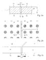
- FIGS. 1a to 1c are aligned with the state of the art, as it exists in the spatula technique.
- Perforated plates 1 and 1 ' are laid in a composite. They each have a back surface 3 or 3 'a visible surface 4 or 4' and edge surfaces 5 and 5 'on.
- a1 which is the same in the conventional spatula technique, ie the distance a1 is in the plane of the Visible surface 4, 4 'with respect to the region of the plane of the back surface 3, 3' completely the same.
- This distance is usually about 4 mm.
- the filler is pressed by means of a suitable tool, such as spatula. It was recognized that usually no uniform filling of the joint 2 with the filler is possible.
- FIGS. 2a to 2c are aligned with the state of the art, as it exists in the adhesive technology. Corresponding reference numerals are increased by the amount 10 compared to the spatula technique. Again, the corresponding distance a11 in the region of the plane of the visible surface 14, 14 'with respect to the region of the plane of the back surface 13, 13' completely the same. This distance a11 is usually about 2 mm. It is observed that the paste-like adhesive to be introduced into the joint area 12 is not able to distribute itself uniformly in the joint area.
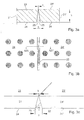
- FIGS. 3a to 3c give the joint system of the invention again.
- Perforated plates 21 and 21 ' are laid in a composite. They each have a back surface 23 or 23 'a visible surface 24 or 24' and edge surfaces 25 and 25 'on.
- the distance c in the region of the plane of the visible surface 4, 4 ' is considerably greater than the distance b in the region of the plane of the back surface 3, 3'.
- This distance c should be best in the range of 3, 6 to 4.5 mm at a thickness h of the respective perforated plate of 12.5 mm.
- the distance b should best have a dimension of about 0.2 mm at a thickness h of the respective perforated plate of 12.5 mm.
- the edge surfaces 25 and 25 are usually performed perfectly flat. However, the surfaces of the edges of the perforated plates can also be increased by various measures, such as grooves, bulges tend to achieve higher adhesion forces for receiving the adhesive or filler. If the surfaces of the edges are made completely flat, a characteristic V-shaped structure of the joint system is produced in cross-section.
- the distance b provided with 0.2 mm is already small with respect to conventional dimensions of a perforated plate and in the assembly of the plates, for example, on a substructure, hard to miss, it may prove advantageous, this distance through in the perforated plate in Ensure area of the rear panel integrated spacers.
- the adjacent laid perforated plates form in the embodiment according to the invention a joint system with the characteristic V-shaped cross-section.
- a putty with recommended by the manufacturer of the perforated plate or plasterboard composition is pressed by means of a suitable tool, such as spatula in the defined by the edge surfaces 25 - 25 'joint system.
- a suitable tool such as spatula
- the construction worker can follow, so to speak positively motivated, how the filler introduced by him in the space between the edge surfaces 25 - 25 'actually remains in the desired manner. It can then also be provided that a small projection of the filler is formed opposite to the surface of the visible side of the perforated plate, so that after solidification of the filler, z. B.
- the level of the plane of the visible surface of the perforated plate is not fallen below and smaller protrusions of the solidified filler can be easily sanded.
- the visual requirements for the visible sides 24 - 24 'of the perforated plate including the machined area in the region of the joint system according to the invention in the entire relevant perforated plate composite can then be fully met.
- the perforated plates are used for the achievement of a particular room acoustics, the full filling of the space between the edge surfaces adjacent laid perforated plates with solidified filling material for the individual perforated plate present properties even in the perforated plate composite to full advantage.
Abstract
Description
Die Erfindung betrifft ein Fugensystem für Lochplatten. Lochplatten, insbesondere Gipslochplatten weisen eine Sichtfläche, eine Rückenfläche und vier Kantenflächen auf. Sie werden üblicherweise im Verbund gegenüber einer Wand- oder Deckenfläche verlegt. Meist wird eine Unterkonstruktion verwendet, um die Lochplatten auf Abstand gegenüber der Wand- oder Deckenfläche zu verlegen. Die Lochplatten dienen meist dazu, die Akustik in Räumen zu verbessern, wozu die Rückenfläche gewöhnlich noch eine besonders ausgebildete Schicht aufweist, um die Schallwellen zu dämpfen. Die Schicht auf der Rückenseite kann auch so ausgebildet sein, dass eine Verklebung mit der Unterkonstruktion möglich ist. Der Übergangsbereich von einer zu anderen, benachbarten Lochplatte nach deren Anbringung an der Wand oder Decke bzw. an der dafür vorgesehenen Unterkonstruktion, bildet ein Fugensystem. Zum Fugensystem gehören also die Kantenflächen benachbart verlegter Lochplatten.The invention relates to a joint system for perforated plates. Perforated plates, in particular plaster-perforated plates, have a visible surface, a back surface and four edge surfaces. They are usually laid in a composite against a wall or ceiling surface. Usually, a substructure is used to lay the perforated plates at a distance from the wall or ceiling surface. The perforated plates are usually used to improve the acoustics in rooms, to which the back surface usually still has a specially trained layer to dampen the sound waves. The layer on the back side can also be designed so that an adhesion to the substructure is possible. The transition region from one to another adjacent perforated plate after its attachment to the wall or ceiling or to the substructure provided for this purpose forms a joint system. So the joint system includes the edge surfaces adjacent laid perforated plates.
Herkömmlicherweise sind die Kantenflächen von zwei benachbart verlegten Lochplatten parallel bezüglich jeder von zwei gedachten Koordinatenachsen, die die Ebene der Kantenfläche einer Lochplatte definiert, ausgerichtet. Der lotrechte Abstand zwischen den Kantenflächen beträgt ca. 2 mm, wenn eine so genannte Klebetechnik zur Verbindung entlang der Fuge der benachbart verlegten Lochplatten verwendet wird. Wird jedoch eine Spachteltechnik zu Verbindung entlang der Fuge der benachbart verlegten Lochplatten verwendet, so beträgt der lotrechte Abstand zwischen den Kantenflächen ca. 4 mm.Conventionally, the edge surfaces of two adjacently laid apertured plates are aligned parallel with respect to each of two imaginary coordinate axes defining the plane of the edge surface of a perforated plate. The vertical distance between the edge surfaces is about 2 mm, if a so-called gluing technique is used for the connection along the joint of the adjacent laid perforated plates. However, if a spatula technique is used to connect along the joint of the adjacent laid perforated plates, then the vertical distance between the edge surfaces is about 4 mm.
Es wurde erkannt, dass sowohl bei der Klebetechnik als auch bei der Spachteltechnik keine vollständige bzw. gleichmäßige Ausfüllung der Fuge möglich ist, womit auch die der Lochplatte bzw. deren Verbund zugedachte begünstigende akustische Eigenschaften zumindest teilweise wieder verloren gehen. Ferner ist meist Klebematerial oder Spachtelmaterial in ungleichmäßiger Weise überstehend gegenüber der Ebene der Sichtfläche der Lochplatte vorhanden, was eine schwierige Nachbearbeitung erforderlich macht.It was recognized that both in the adhesive technique and in the spatula technique no complete or uniform filling of the joint is possible, which also at least partially lost the favoring acoustic properties attributed to the perforated plate or its composite. Furthermore, usually adhesive material or putty material is present in an uneven manner over the plane of the visible surface of the perforated plate, which requires a difficult post-processing.
Die Aufgabe der Erfindung besteht daher darin, ein obig beschriebenes Fugensystem geeigneter zu gestalten.The object of the invention is therefore to make a joint system described above more suitable.
Die Lösung dieser Aufgabe besteht darin, dass das Fugensystem so ausgebildet ist, dass im Wesentlichen ein Abstand benachbarter Lochplatten in der Ebene der Sichtfläche der Lochplatten erheblich größer ist, als im Wesentlichen ein Abstand benachbarter Lochplatten in der Ebene der Rückenfläche benachbarter Lochplatten.The solution to this problem is that the joint system is formed so that substantially a distance between adjacent perforated plates in the plane of the visible surface of the perforated plates is substantially greater than substantially a distance of adjacent perforated plates in the plane of the back surface of adjacent perforated plates.
Ein solches erfindungsgemäßes Fugensystem erlaubt insbesondere bei Anwendung der Spachteltechnik ein gleichmäßiges Einbringen der Spachtelmasse in den Raum, der zwischen den Kantenflächen der benachbart angebrachten Lochplatten vorliegt. Der Bauausführende Handwerker kann sozusagen positiv motiviert mitverfolgen, wie die von ihm eingebrachte Spachtelmasse in dem Raum zwischen den Kantenflächen auch tatsächlich in gewollter Weise verbleibt. Es kann auch gewollt sein, dass ein kleiner Überstand der Spachtelmasse gegenüber der Oberfläche der Sichtseite der Lochplatte ausgebildet wird, so dass nach Verfestigung der Spachtelmasse, z. B durch Austrocknung und einem möglichen Schwund, das Niveau der Ebene der Sichtfläche der Lochplatte keinesfalls unterschritten wird und kleinere Überstände der verfestigten Spachtelmasse leicht abgeschliffen werden können, so dass den optischen Anforderungen an die Sichtseite der Lochplatte bzw. dem diesbezüglichen Lochplattenverbund voll entsprochen werden kann. Durch die vollständige Ausfüllung des Raumes zwischen den Kantenflächen benachbart verlegter Lochplatten mit verfestigter Füllmasse kommen die dem Lochplattenverbund zugedachten Eigenschaften, wie insbesondere die gewünschte Akustik, voll zu Geltung.Such a joint system according to the invention allows, in particular when using the spatula technique, a uniform introduction of the filler into the space which exists between the edge surfaces of the adjacent perforated plates. The construction worker can, so to speak positively motivated follow, as the putty introduced by him in the space between the edge surfaces actually remains in the desired manner. It may also be desired that a small projection of the filler is formed opposite to the surface of the visible side of the perforated plate, so that after solidification of the filler, z. B by dehydration and a possible loss, the level the level of the visible surface of the perforated plate is by no means undershot and smaller protrusions of the solidified filler can be easily abraded, so that the optical requirements for the visible side of the perforated plate or the relevant perforated plate composite can be fully met. Due to the complete filling of the space between the edge surfaces of adjacent laid perforated plates with solidified filling material, the properties intended for the perforated plate composite, such as, in particular, the desired acoustics, come into their own.
Obwohl natürlich der Abstand gegenüber einem mittleren Abstand benachbarter Lochplatten in der Ebene der Sichtflächen der Lochplatten variieren kann, z. B. wenn eine besondere Geometrie der Oberflächen der Kantenflächen gewählt sein sollte, wird doch bevorzugt ein gleichmäßiger Abstand benachbarter Lochplatten in der Ebene der Sichtflächen der Lochplatten entlang der gesamten Länge oder Breite der jeweilig benachbarten Lochplatte bevorzugt, da dies mit Fertigungsvorteilen für die betreffende Lochplatte einhergeht.Although, of course, the distance to a mean distance between adjacent perforated plates in the plane of the visible surfaces of the perforated plates may vary, for. Example, if a particular geometry of the surfaces of the edge surfaces should be selected, but a preferred uniform spacing of adjacent perforated plates in the plane of the visible surfaces of the perforated plates along the entire length or width of the respective adjacent perforated plate is preferred because this is associated with manufacturing advantages for the respective perforated plate ,
Es wurde herausgefunden, dass die erfindungsgemäßen Vorteile sich besonders günstig ergeben, wenn der Abstand benachbarter Lochplatten in der Ebene der Sichtflächen der Lochplatten sich im Bereich von 3,6 mm bis 4,5 mm bei einer Stärke der jeweiligen Lochplatte von ca. 12,5 mm befindet. Ferner hat es sich als günstig herausgestellt, wenn der Abstand benachbarter Lochplatten in der Ebene der Rückenflächen der Lochplatten ca. 0,2 mm bei, wie bereits erwähnter Stärke der jeweiligen Lochplatte von ca. 12,5 mm ist.It has been found that the advantages of the invention are particularly favorable when the distance between adjacent perforated plates in the plane of the visible surfaces of the perforated plates in the range of 3.6 mm to 4.5 mm at a thickness of the respective perforated plate of about 12.5 mm is located. Further, it has been found to be advantageous if the distance between adjacent perforated plates in the plane of the back surfaces of the perforated plates is about 0.2 mm at, as already mentioned strength of the respective perforated plate of about 12.5 mm.
Die Oberflächen der Kanten der Lochplatten können durch verschiedenartige Maßnahmen, wie Rillen, Wölbungen tendenziell vergrößert werden, um höhere Adhäsionskräfte für die Aufnahme der Klebe- oder Spachtelmasse zu erreichen, was im Rahmen der Erfindung liegt, jedoch wird es bevorzugt, die Fläche einer Kante einer jeweiligen Lochplatte eben auszuführen, was zu einer vereinfachten Fertigung der zum erfindungsgemäßen Fugensystem gehörenden Lochplatte führt. In einem solchen Fall ist der Querschnitt des erfindungsgemäßen Fugensystems auch ziemlich genau V-förmig. Von der V-Form geringfügig oder in etwas größerem Umfang abweichende Querschnittsformen gehören jedoch auch zur Erfindung.The surfaces of the edges of the perforated plates can be increased by various measures, such as grooves, bulges to achieve higher adhesion forces for receiving the adhesive or filler, which is within the scope of the invention, but it is preferred, the surface of an edge of a To execute the respective perforated plate level, resulting in a simplified production of the joint system according to the invention belonging perforated plate. In such a case, the cross section of the joint system according to the invention is also fairly exactly V-shaped. Of the V-shape slightly or slightly larger extent deviating cross-sectional shapes, however, also belong to the invention.
Ferner erweist es sich als günstig, wenn der vorbestimmte Abstand der benachbarten Lochplatten in der Ebene der Rückenflächen der der Lochplatten durch in die Lochplatte integrierte Abstandselemente sichergestellt werden kann, da dann die Montage der Lochplatten, z. B. gegenüber der Unterkonstruktion ohne Zuhilfenahme eines Messwerkzeuges erfolgen kann. Die Abstandselemente sind dann in Bezug auf gegenüberliegende Längsseiten bzw. Breitenseiten einer Lochplatte so versetzt angeordnet dass eine ungewollte Addition von des vorbestimmten Abstandes ausgeschlossen werden kann bzw. es wird nur jeweils eine Längsseite bzw. nur jeweils eine Breitenseite einer Lochplatte mit solchen Abstandselementen ausgerüstet. Werden die integrierten Abstandselemente an allen Kanten der Abstandselemente vorgesehen, kann hiermit auch ein Kantenschutz erreicht werden.Furthermore, it proves to be advantageous if the predetermined distance of the adjacent perforated plates in the plane of the back surfaces of the perforated plates can be ensured by integrated into the perforated plate spacers, since then the assembly of the perforated plates, for. B. can be done with respect to the substructure without the aid of a measuring tool. The spacer elements are then arranged offset with respect to opposite longitudinal sides or broad sides of a perforated plate so that an unwanted addition of the predetermined distance can be excluded or only one longitudinal side or only one width side of a perforated plate is equipped with such spacers. If the integrated spacer elements are provided on all edges of the spacer elements, edge protection can also be achieved hereby.
Die Erfindung wird nachfolgend anhand einer Zeichnung mit mehreren Figuren weiter erläutert. Es zeigen:
- Fig. 1a:
- einen Querschnitt, entsprechend der Schnittlinie A1 - A1' in
Fig. 1b , jedoch leicht vergrößert dargestellt, in der Anordnung benachbart verlegter Lochplatten, vorgesehen für die Spachteltechnik; - Fig. 1b:
- eine Draufsicht auf die Sichtseite in der Anordnung benachbart verlegter Lochplatten, vorgesehen für die Spachteltechnik;
- Fig. 1c:
- eine perspektivische Ansicht in der Anordnung benachbart verlegter Lochplatten, vorgesehen für die Spachteltechnik;
- Fig. 2a:
- einen Querschnitt, entsprechend der Schnittlinie A11 - A11' in
Fig. 2b , jedoch leicht vergrößert dargestellt, in der Anordnung benachbart verlegter Lochplatten, vorgesehen für die Klebetechnik; - Fig. 2b:
- eine Draufsicht auf die Sichtseite in der Anordnung benachbart verlegter Lochplatten, vorgesehen für die Klebetechnik;
- Fig. 2c:
- eine perspektivische Ansicht in der Anordnung benachbart verlegter Lochplatten, vorgesehen für die Klebetechnik;
- Fig. 3a:
- einen Querschnitt, entsprechend der Schnittlinie A21 - A21' von
Fig. 3b , jedoch leicht vergrößert dargestellt, in der Anordnung benachbart verlegter Lochplatten, entsprechend dem erfindungsgemäßen Fugensystem; - Fig. 3b:
- eine Draufsicht auf die Sichtseite in der Anordnung benachbart verlegter Lochplatten, entsprechend dem erfindungsgemäßen Fugensystem;
- Fig. 3c:
- eine perspektivische Ansicht in der Anordnung benachbart verlegter Lochplatten, entsprechend dem erfindungsgemäßen Fugensystem;
- Fig. 1a:
- a cross section corresponding to the section line A1 - A1 'in
Fig. 1b but shown slightly enlarged, in the arrangement of adjacent laid perforated plates, intended for the spatula technique; - Fig. 1b:
- a plan view of the visible side in the arrangement of adjacent laid perforated plates, provided for the spatula technique;
- Fig. 1c:
- a perspective view in the arrangement of adjacent laid perforated plates, provided for the spatula technique;
- Fig. 2a:
- a cross section corresponding to the section line A11 - A11 'in
Fig. 2b but shown slightly enlarged, in the arrangement of adjacent laid perforated plates, intended for the gluing technique; - Fig. 2b:
- a plan view of the visible side in the arrangement of adjacent laid perforated plates, intended for the gluing technique;
- Fig. 2c:
- a perspective view in the arrangement of adjacent laid perforated plates, intended for the gluing technique;
- Fig. 3a:
- a cross section corresponding to the section line A21 - A21 'of
Fig. 3b but shown slightly enlarged, in the arrangement of adjacent laid perforated plates, according to the joint system according to the invention; - 3b:
- a plan view of the visible side in the arrangement adjacent laid perforated plates, according to the joint system according to the invention;
- 3c:
- a perspective view in the arrangement adjacent laid perforated plates, according to the joint system according to the invention;
Die
Die
Die
Die benachbart verlegten Lochplatten, insbesondere Gipslochplatten, bilden in der erfindungsgemäßen Ausführungsform ein Fugensystem mit dem charakteristischen V-förmigen Querschnitt.The adjacent laid perforated plates, in particular gypsum perforated plates, form in the embodiment according to the invention a joint system with the characteristic V-shaped cross-section.
Eine Spachtelmasse mit vom Hersteller der Lochplatte bzw. Gipslochplatte empfohlener Zusammensetzung wird mittels eines geeigneten Werkzeuges, wie Spachtel in das durch die Kantenflächen 25 - 25' definierte Fugensystem eingedrückt. Dabei kann der Bauausführende Handwerker kann sozusagen positiv motiviert mitverfolgen, wie die von ihm eingebrachte Spachtelmasse in dem Raum zwischen den Kantenflächen 25 - 25' auch tatsächlich in gewollter Weise verbleibt. Es kann dann auch vorgesehen sein, dass ein kleiner Überstand der Spachtelmasse gegenüber der Oberfläche der Sichtseite der Lochplatte ausgebildet wird, so dass nach Verfestigung der Spachtelmasse, z. B. durch Austrocknung und einem möglichen Schwund, das Niveau der Ebene der Sichtfläche der Lochplatte keinesfalls unterschritten wird und kleinere Überstände der verfestigten Spachtelmasse leicht abgeschliffen werden können. Den optischen Anforderungen an die Sichtseiten 24 - 24' der Lochplatte einschließlich dem bearbeiteten Gebiet im Bereich des erfindungsgemäßen Fugensystems in dem gesamten diesbezüglichen Lochplattenverbund kann dann voll entsprochen werden kann. Soweit die Lochplatten für die Erreichung einer bestimmten Raumakustik eingesetzt werden, kommen durch die vollständige Ausfüllung des Raumes zwischen den Kantenflächen benachbart verlegter Lochplatten mit verfestigter Füllmasse die für die einzelne Lochplatte vorliegenden Eigenschaften auch bei dem Lochplattenverbund voll zu Geltung.A putty with recommended by the manufacturer of the perforated plate or plasterboard composition is pressed by means of a suitable tool, such as spatula in the defined by the edge surfaces 25 - 25 'joint system. In this case, the construction worker can follow, so to speak positively motivated, how the filler introduced by him in the space between the edge surfaces 25 - 25 'actually remains in the desired manner. It can then also be provided that a small projection of the filler is formed opposite to the surface of the visible side of the perforated plate, so that after solidification of the filler, z. B. by dehydration and a possible shrinkage, the level of the plane of the visible surface of the perforated plate is not fallen below and smaller protrusions of the solidified filler can be easily sanded. The visual requirements for the visible sides 24 - 24 'of the perforated plate including the machined area in the region of the joint system according to the invention in the entire relevant perforated plate composite can then be fully met. As far as the perforated plates are used for the achievement of a particular room acoustics, the full filling of the space between the edge surfaces adjacent laid perforated plates with solidified filling material for the individual perforated plate present properties even in the perforated plate composite to full advantage.
- 1, 1'1, 1 '
- Gips- LochplatteGypsum perforated plate
- 22
- Fugensystem, herkömmlichJoint system, conventional
- 3, 3'3, 3 '
- Rückenflächebackrest
- 4, 4'4, 4 '
- Sichtflächeviewing area
- 5, 5'5, 5 '
- Kantenflächeedge surface
- a1, a11a1, a11
- Abstanddistance
- hH
- Stärke von LochplatteThickness of perforated plate
- 11, 11'11, 11 '
- Gips- LochplatteGypsum perforated plate
- 2222
- Fugensystem, herkömmlichJoint system, conventional
- 13, 13'13, 13 '
- Rückenflächebackrest
- 14,14'14.14 '
- Sichtflächeviewing area
- 15, 15'15, 15 '
- Kantenflächeedge surface
- 21, 21'21, 21 '
- Gips- LochplatteGypsum perforated plate
- 2222
- Fugensystem, erfindungsgemäßJoint system, according to the invention
- 23, 23'23, 23 '
- Rückenflächebackrest
- 24,24'24.24 '
- Sichtflächeviewing area
- 25, 25'25, 25 '
- Kantenflächeedge surface
- bb
- kleinerer Abstand, erfindungsgemäßes Fugensystemsmaller distance, joint system according to the invention
- cc
- größerer Abstand, erfindungsgemäßes Fugensystemgreater distance, joint system according to the invention
Claims (8)
Applications Claiming Priority (1)
| Application Number | Priority Date | Filing Date | Title |
|---|---|---|---|
| DE200820016614 DE202008016614U1 (en) | 2008-12-12 | 2008-12-12 | Joint system for perforated boards |
Publications (2)
| Publication Number | Publication Date |
|---|---|
| EP2199478A2 true EP2199478A2 (en) | 2010-06-23 |
| EP2199478A3 EP2199478A3 (en) | 2011-06-08 |
Family
ID=40418696
Family Applications (1)
| Application Number | Title | Priority Date | Filing Date |
|---|---|---|---|
| EP09178824A Withdrawn EP2199478A3 (en) | 2008-12-12 | 2009-12-11 | Joining system for perforated boards |
Country Status (2)
| Country | Link |
|---|---|
| EP (1) | EP2199478A3 (en) |
| DE (1) | DE202008016614U1 (en) |
Cited By (1)
| Publication number | Priority date | Publication date | Assignee | Title |
|---|---|---|---|---|
| WO2012004220A3 (en) * | 2010-07-09 | 2012-06-28 | Saint-Gobain Placo Sas | Perforated gypsum-based boards and method for laying the same |
Family Cites Families (4)
| Publication number | Priority date | Publication date | Assignee | Title |
|---|---|---|---|---|
| FR2520408A1 (en) * | 1982-01-22 | 1983-07-29 | Smac Acieroid | EXTERNAL INSULATION ELEMENT AND CLOTHING USING SUCH ELEMENTS |
| AU643751B2 (en) * | 1989-12-14 | 1993-11-25 | J P Walls, Inc. | Predecorated wallboard joint and method of joining predecorated wallboards to form a concealed joint |
| DE20312122U1 (en) * | 2003-08-01 | 2003-12-18 | Möding Keramikfassaden GmbH | Curtain facade construction has support profiles connected to base support profiles via profiled holders each connected to base support profile via screw, plug-in or riveted fastening device installed in support profile holder |
| DE202007006920U1 (en) * | 2007-05-14 | 2007-08-16 | Geipel, Udo | Plate element of molded material e.g. for gypsum cardboard, for wall and floor lining, has adjusting unit with multiple projections, arranged at predetermined distances to each other and multiple slots are arranged in plate elements |
-
2008
- 2008-12-12 DE DE200820016614 patent/DE202008016614U1/en not_active Expired - Lifetime
-
2009
- 2009-12-11 EP EP09178824A patent/EP2199478A3/en not_active Withdrawn
Non-Patent Citations (1)
| Title |
|---|
| None |
Cited By (1)
| Publication number | Priority date | Publication date | Assignee | Title |
|---|---|---|---|---|
| WO2012004220A3 (en) * | 2010-07-09 | 2012-06-28 | Saint-Gobain Placo Sas | Perforated gypsum-based boards and method for laying the same |
Also Published As
| Publication number | Publication date |
|---|---|
| EP2199478A3 (en) | 2011-06-08 |
| DE202008016614U1 (en) | 2009-03-05 |
Similar Documents
| Publication | Publication Date | Title |
|---|---|---|
| EP2335916A1 (en) | Wood panel for ceilings or walls | |
| EP2591181B1 (en) | Perforated gypsum-based boards and method for laying the same | |
| EP3303729A1 (en) | Method for laying tiles | |
| DE202014000932U1 (en) | Drywall and drywall | |
| DE3329113A1 (en) | DEVICE FOR FIXING CERAMIC SURFACE ELEMENTS TO A SUBSTRATE | |
| DE102014005312A1 (en) | Method and device for fixing plate elements | |
| EP2199478A2 (en) | Joining system for perforated boards | |
| DE955816C (en) | Connection of flat, curved or similarly designed plate-shaped components, e.g. Intermediate walls, on the components surrounding them | |
| DE102007002639A1 (en) | Hybrid profile for closing of walls and floor covering, has two metallurgically different leveled sheeting bands, which are joined together along their longitudinal edges before, during or after molding process by deformation technology | |
| DE102006002910A1 (en) | Assembly plate used in the production of a corner element for heating pipes and cables comprises a wedge which is lower than the depth of the groove | |
| DE10054978B4 (en) | Gypsum plaster board with a randseitingen extending over the entire length of a side edge recess, method for producing and using the same | |
| DE102015122919A1 (en) | Wood brick | |
| DE102020112180A1 (en) | Method for forming an inside corner between at least two building panels of a wall structure that adjoin one another at an angle, in particular a wall structure of a prefabricated house made using a timber frame construction or a timber panel construction | |
| EP1811099A2 (en) | Building element for making a corner element | |
| DE202012011757U1 (en) | Isolated building facade | |
| DE102010026602A1 (en) | Perforated plate e.g. cardboard perforated plate at ceiling, has spacing elements arranged at side surfaces and made of plastic material or stainless metal, where total length of spacing elements is less than that of side surfaces | |
| EP3546674B1 (en) | Façade system for forming a thermal insulation compound façade | |
| DE112017000867T5 (en) | Bauplattenherstellung | |
| DE102012010265A1 (en) | High-performance thermal insulation board | |
| DE102011112378A1 (en) | joint sealing | |
| DE202015009133U1 (en) | Set for making a lining of an interior corner | |
| DE102006008686A1 (en) | Plate-like lining system for joint-less wall or ceiling coverings comprises plate-like elements having a surface on the room side and an opposite-lying surface | |
| WO2017017144A1 (en) | Wall construction and mounting method | |
| BE1025589B1 (en) | Thermally insulated wall and method for its manufacture | |
| BE1023265B1 (en) | Insulating facade panel |
Legal Events
| Date | Code | Title | Description |
|---|---|---|---|
| PUAI | Public reference made under article 153(3) epc to a published international application that has entered the european phase |
Free format text: ORIGINAL CODE: 0009012 |
|
| AK | Designated contracting states |
Kind code of ref document: A2 Designated state(s): AT BE BG CH CY CZ DE DK EE ES FI FR GB GR HR HU IE IS IT LI LT LU LV MC MK MT NL NO PL PT RO SE SI SK SM TR |
|
| AX | Request for extension of the european patent |
Extension state: AL BA RS |
|
| PUAL | Search report despatched |
Free format text: ORIGINAL CODE: 0009013 |
|
| AK | Designated contracting states |
Kind code of ref document: A3 Designated state(s): AT BE BG CH CY CZ DE DK EE ES FI FR GB GR HR HU IE IS IT LI LT LU LV MC MK MT NL NO PL PT RO SE SI SK SM TR |
|
| AX | Request for extension of the european patent |
Extension state: AL BA RS |
|
| 17P | Request for examination filed |
Effective date: 20111207 |
|
| 17Q | First examination report despatched |
Effective date: 20130711 |
|
| STAA | Information on the status of an ep patent application or granted ep patent |
Free format text: STATUS: THE APPLICATION IS DEEMED TO BE WITHDRAWN |
|
| 18D | Application deemed to be withdrawn |
Effective date: 20130702 |