EP2198899A2 - Device and method for producing same - Google Patents
Device and method for producing same Download PDFInfo
- Publication number
- EP2198899A2 EP2198899A2 EP20090177440 EP09177440A EP2198899A2 EP 2198899 A2 EP2198899 A2 EP 2198899A2 EP 20090177440 EP20090177440 EP 20090177440 EP 09177440 A EP09177440 A EP 09177440A EP 2198899 A2 EP2198899 A2 EP 2198899A2
- Authority
- EP
- European Patent Office
- Prior art keywords
- functional element
- base body
- layer
- plasma
- chemical treatment
- Prior art date
- Legal status (The legal status is an assumption and is not a legal conclusion. Google has not performed a legal analysis and makes no representation as to the accuracy of the status listed.)
- Granted
Links
Images
Classifications
-
- A—HUMAN NECESSITIES
- A61—MEDICAL OR VETERINARY SCIENCE; HYGIENE
- A61L—METHODS OR APPARATUS FOR STERILISING MATERIALS OR OBJECTS IN GENERAL; DISINFECTION, STERILISATION OR DEODORISATION OF AIR; CHEMICAL ASPECTS OF BANDAGES, DRESSINGS, ABSORBENT PADS OR SURGICAL ARTICLES; MATERIALS FOR BANDAGES, DRESSINGS, ABSORBENT PADS OR SURGICAL ARTICLES
- A61L31/00—Materials for other surgical articles, e.g. stents, stent-grafts, shunts, surgical drapes, guide wires, materials for adhesion prevention, occluding devices, surgical gloves, tissue fixation devices
- A61L31/02—Inorganic materials
- A61L31/022—Metals or alloys
-
- A—HUMAN NECESSITIES
- A61—MEDICAL OR VETERINARY SCIENCE; HYGIENE
- A61L—METHODS OR APPARATUS FOR STERILISING MATERIALS OR OBJECTS IN GENERAL; DISINFECTION, STERILISATION OR DEODORISATION OF AIR; CHEMICAL ASPECTS OF BANDAGES, DRESSINGS, ABSORBENT PADS OR SURGICAL ARTICLES; MATERIALS FOR BANDAGES, DRESSINGS, ABSORBENT PADS OR SURGICAL ARTICLES
- A61L31/00—Materials for other surgical articles, e.g. stents, stent-grafts, shunts, surgical drapes, guide wires, materials for adhesion prevention, occluding devices, surgical gloves, tissue fixation devices
- A61L31/08—Materials for coatings
- A61L31/10—Macromolecular materials
-
- A—HUMAN NECESSITIES
- A61—MEDICAL OR VETERINARY SCIENCE; HYGIENE
- A61L—METHODS OR APPARATUS FOR STERILISING MATERIALS OR OBJECTS IN GENERAL; DISINFECTION, STERILISATION OR DEODORISATION OF AIR; CHEMICAL ASPECTS OF BANDAGES, DRESSINGS, ABSORBENT PADS OR SURGICAL ARTICLES; MATERIALS FOR BANDAGES, DRESSINGS, ABSORBENT PADS OR SURGICAL ARTICLES
- A61L31/00—Materials for other surgical articles, e.g. stents, stent-grafts, shunts, surgical drapes, guide wires, materials for adhesion prevention, occluding devices, surgical gloves, tissue fixation devices
- A61L31/14—Materials characterised by their function or physical properties, e.g. injectable or lubricating compositions, shape-memory materials, surface modified materials
- A61L31/148—Materials at least partially resorbable by the body
-
- A—HUMAN NECESSITIES
- A61—MEDICAL OR VETERINARY SCIENCE; HYGIENE
- A61L—METHODS OR APPARATUS FOR STERILISING MATERIALS OR OBJECTS IN GENERAL; DISINFECTION, STERILISATION OR DEODORISATION OF AIR; CHEMICAL ASPECTS OF BANDAGES, DRESSINGS, ABSORBENT PADS OR SURGICAL ARTICLES; MATERIALS FOR BANDAGES, DRESSINGS, ABSORBENT PADS OR SURGICAL ARTICLES
- A61L31/00—Materials for other surgical articles, e.g. stents, stent-grafts, shunts, surgical drapes, guide wires, materials for adhesion prevention, occluding devices, surgical gloves, tissue fixation devices
- A61L31/14—Materials characterised by their function or physical properties, e.g. injectable or lubricating compositions, shape-memory materials, surface modified materials
- A61L31/18—Materials at least partially X-ray or laser opaque
-
- A—HUMAN NECESSITIES
- A61—MEDICAL OR VETERINARY SCIENCE; HYGIENE
- A61L—METHODS OR APPARATUS FOR STERILISING MATERIALS OR OBJECTS IN GENERAL; DISINFECTION, STERILISATION OR DEODORISATION OF AIR; CHEMICAL ASPECTS OF BANDAGES, DRESSINGS, ABSORBENT PADS OR SURGICAL ARTICLES; MATERIALS FOR BANDAGES, DRESSINGS, ABSORBENT PADS OR SURGICAL ARTICLES
- A61L2420/00—Materials or methods for coatings medical devices
- A61L2420/02—Methods for coating medical devices
-
- C—CHEMISTRY; METALLURGY
- C25—ELECTROLYTIC OR ELECTROPHORETIC PROCESSES; APPARATUS THEREFOR
- C25D—PROCESSES FOR THE ELECTROLYTIC OR ELECTROPHORETIC PRODUCTION OF COATINGS; ELECTROFORMING; APPARATUS THEREFOR
- C25D11/00—Electrolytic coating by surface reaction, i.e. forming conversion layers
- C25D11/02—Anodisation
- C25D11/024—Anodisation under pulsed or modulated current or potential
-
- C—CHEMISTRY; METALLURGY
- C25—ELECTROLYTIC OR ELECTROPHORETIC PROCESSES; APPARATUS THEREFOR
- C25D—PROCESSES FOR THE ELECTROLYTIC OR ELECTROPHORETIC PRODUCTION OF COATINGS; ELECTROFORMING; APPARATUS THEREFOR
- C25D11/00—Electrolytic coating by surface reaction, i.e. forming conversion layers
- C25D11/02—Anodisation
- C25D11/026—Anodisation with spark discharge
-
- C—CHEMISTRY; METALLURGY
- C25—ELECTROLYTIC OR ELECTROPHORETIC PROCESSES; APPARATUS THEREFOR
- C25D—PROCESSES FOR THE ELECTROLYTIC OR ELECTROPHORETIC PRODUCTION OF COATINGS; ELECTROFORMING; APPARATUS THEREFOR
- C25D11/00—Electrolytic coating by surface reaction, i.e. forming conversion layers
- C25D11/02—Anodisation
- C25D11/04—Anodisation of aluminium or alloys based thereon
- C25D11/16—Pretreatment, e.g. desmutting
-
- C—CHEMISTRY; METALLURGY
- C25—ELECTROLYTIC OR ELECTROPHORETIC PROCESSES; APPARATUS THEREFOR
- C25D—PROCESSES FOR THE ELECTROLYTIC OR ELECTROPHORETIC PRODUCTION OF COATINGS; ELECTROFORMING; APPARATUS THEREFOR
- C25D11/00—Electrolytic coating by surface reaction, i.e. forming conversion layers
- C25D11/02—Anodisation
- C25D11/26—Anodisation of refractory metals or alloys based thereon
-
- Y—GENERAL TAGGING OF NEW TECHNOLOGICAL DEVELOPMENTS; GENERAL TAGGING OF CROSS-SECTIONAL TECHNOLOGIES SPANNING OVER SEVERAL SECTIONS OF THE IPC; TECHNICAL SUBJECTS COVERED BY FORMER USPC CROSS-REFERENCE ART COLLECTIONS [XRACs] AND DIGESTS
- Y10—TECHNICAL SUBJECTS COVERED BY FORMER USPC
- Y10T—TECHNICAL SUBJECTS COVERED BY FORMER US CLASSIFICATION
- Y10T29/00—Metal working
- Y10T29/49—Method of mechanical manufacture
- Y10T29/49826—Assembling or joining
- Y10T29/49908—Joining by deforming
- Y10T29/49938—Radially expanding part in cavity, aperture, or hollow body
- Y10T29/49943—Riveting
Definitions
- the present invention relates to a device, in particular for medical use as an endoprosthesis, preferably as an intraluminal endoprosthesis, with a base body which consists at least partially of a metallic material, and with a functional element attached to the base body, which at least in a part of its volume compared with the material of the base body has different metallic material composition, which preferably at least partially radiopaque and / or radiopaque material, as well as a method for producing such a device.
- Stents are endovascular prostheses (endoprostheses) or implants that can be used to treat stenoses (vasoconstriction). They have a base body in the form of a hollow cylindrical or tubular base grid, which is open at both longitudinal ends of the tubes. The tubular base grid of such an endoprosthesis is inserted into the vessel to be treated and serves to support the vessel.
- the metallic materials may form a biodegradable material, wherein polymeric, biodegradable materials may be included.
- Biodegradation is understood to mean hydrolytic, enzymatic and other metabolism-related degradation processes in the living organism, which are primarily caused by the body fluids which come into contact with the endoprosthesis and lead to a gradual dissolution of at least large parts of the endoprosthesis. Synonymous with the term biodegradation, the term biocorrosion is often used. The term bioresorption covers the subsequent absorption of the degradation products by the living organism.
- suitable materials may also consist of several materials.
- suitable polymeric compounds are polymers from the group of cellulose, collagen, albumin, casein, polysaccharides (PSAC), polylactide (PLA), poly-L-lactide (PLLA), polyglycol (PGA), poly-D, L-lactide co-glycolide (PDLLA-PGA), polyhydroxybutyric acid (PHB), polyhydroxyvaleric acid (PHV), polyalkylcarbonates, polyorthoesters, polyethylene terephthalate (PET), polymalonic acid (PML), polyanhydrides, polyphosphazenes, polyamino acids and their copolymers, and hyaluronic acid.
- the polymers may be present in pure form, in derivatized form, in the form of blends or as copolymers.
- Metallic biodegradable materials are based on alloys of magnesium, iron, zinc and / or
- the present invention relates to endoprostheses or other devices having a base body whose material contains a metallic material.
- a metallic material In addition to the biodegradable materials mentioned, other metallic materials are also suitable.
- the determination of the position of a stent or other devices is often done by means of imaging methods, for example by means of an X-ray device. Due to the small atomic number and the low density of the biodegradable material magnesium and its alloys, the radiopacity of the medical implants made from it is very low. In order to remedy this disadvantage, it is known to provide medical devices with functional elements which, at least in part of their volume, have a different material composition compared to the material of the basic body. In particular, these so-called markers or functional elements contain a material which more strongly absorbs the x-rays and / or other electromagnetic radiation (hereinafter referred to as radiopaque or radiopaque material) than the material of the basic body.
- radiopaque or radiopaque material a material which more strongly absorbs the x-rays and / or other electromagnetic radiation
- the publication DE 698 36 656 T2 shows and describes a radiopaque marker bioabsorbable marker for use on an implantable endoprosthesis such as a stent.
- the bioabsorbable radiopaque markers have, for example, porous sections which are filled with radiopaque material.
- a marker having hollow, void-like and porous portions filled with radiopaque material is also described.
- the prior art shows a marker formed as an elongated member such as a filament that is wrapped around portions of the implantable endoprosthesis.
- the polymeric sheath minimizes the real contact area of the marker material with the magnesium and suppresses local element bonding.
- the holding forces exerted by the magnesium implant on the x-ray marker are limited due to the low strength of the polymer and the differences in the moduli of elasticity of the two materials. This leads after only a few days to a loss of bond strength and an associated risk of detachment of the X-ray marker from the implant.
- the object of the present invention is therefore to provide a device in which the direct metallic contact of the functional element to the base body is reduced and at the same time a high bond strength is achieved.
- the object is also to provide a cost-effective method for producing such a device.
- Such a device according to the invention has the advantage that the direct metallic contact between the functional element and the base body is reduced and at the same time a high bond strength is achieved. As a result, the degradation of such a device is significantly extended and the whereabouts of the functional element on the device even with advanced degradation ensured.
- the base body has at least one at least largely biodegradable metallic material, preferably magnesium or a magnesium alloy.
- the thickness of the first layer produced on the base body surface by means of the plasma-chemical treatment is about 1 ⁇ m to about 20 ⁇ m, preferably about 2 ⁇ m to about 8 ⁇ m.
- a second layer with at least one polymer from the group comprising parylene, polyurethane and magnesium stearate is arranged on the first layer at least in the border region accessible between the base body and the functional element.
- parylene completely linear, semi-crystalline and uncrosslinked aromatic polymers.
- these polymers can be divided into four basic types, namely Parylene C, Parylene D, Parylene N and Parylene F.
- Parylene can preferably be applied to the functional element by means of a vapor deposition process.
- the functional element preferably comprises one or more X-ray and / or radio-opaque elements or compounds from the group consisting of platinum, iridium, gold, tungsten, molybdenum, niobium, tantalum, yttrium, zirconium, ytterbium or alloys of these metals.
- the second layer has a layer thickness between about 0.5 ⁇ m and about 5 ⁇ m.
- the method according to the invention represents a cost-effective method for producing a device with the above advantages.
- the first layer after the plasma-chemical treatment is rinsed in a solvent, preferably by means of distilled H 2 O and then dried preferably at a temperature of at least 80 ° C, more preferably at least about 100 ° C, wherein the drying preferably in a Convection oven is performed.
- the aqueous solution contains a buffer, preferably potassium dihydrogen phosphate and / or sodium dihydrogen phosphate.
- a buffer preferably potassium dihydrogen phosphate and / or sodium dihydrogen phosphate.
- calcium dihydrogen phosphate can also be contained in the aqueous solution as a buffer, the low water solubility of which can be increased by the addition of complexing agents, such as ethylenediamine.
- the plasma-chemical treatment of the body surface takes place in that a pulsed voltage is applied to the main body, whose amplitude is in a part of the treatment period exceeds a characteristic of the material of the functional element bath voltage and preferably increases in the course of treatment.
- the functional element is attached to the base body by means of pressing, riveting, laser welding and / or electron beam welding.
- the current density in the plasma-chemical treatment is at least about 8 mA / cm 2 .
- the device according to the invention has a layer system, in particular on an absorbable magnesium implant, which is equipped with functioning as an X-ray marker functional elements of tungsten, tantalum, molybdenum, niobium and zirconium and their alloys.
- the X-ray marker is connected to the base body by known technologies such as press-fitting, riveting, laser or electron beam welding.
- the contacting material consists of an aluminum or titanium wire.
- immersion in an aqueous, phosphate-containing solution is followed by immersion in an aqueous, phosphate-containing solution.
- the bath voltage continues to rise, plasma-chemical effects are initially observed on the surface of the main body, which preferably contains magnesium, which cause a mixed phase of oxides and phosphates of the material of the main body.
- the oxide layer continues to grow on the functional element.
- the material of the Functional characteristic bath voltage of, for example, about 230 V for tantalum or 260 V for tungsten is due to a plasmachemic effect conversion of originally pure plasma-chemically generated oxide layer in a phosphate / oxide mixture layer of the functional element surface.
- the thickness of the oxide / phosphate mixture layer on the functional element surface increases depending on the bath voltage.
- the plasma-chemical process must proceed under different conditions than the coating of the individual components. It is particularly advantageous if the respective oxide layers grow slowly, otherwise the oxide with the highest formation enthalpy can not form a coherent layer.
- the slow growth of the oxide layer is achieved according to the invention by long pauses between the voltage pulses. These can be up to 500 milliseconds long. This leads to a recombination of the irregularities in the phosphate and oxide layers of the base body and the functional element caused by the plasma-chemical effects.
- mixed oxides such as, for example, magnesium tantalum oxide and mixed phosphates of the material of the main body and of the functional element are also formed in the short-term stable plasma phase.
- transition zone boundary region of the base body and functional element, which extends to the surface of the untreated device
- the lower corrosion resistance of these internal areas only then affects and accelerates accordingly Corrosion when the overlying oxide and phosphate layers are degraded during aging under corrosive conditions.
- the base body with functional element in the boundary region can also be coated with magnesium stearate without a preceding plasma-chemical oxidation process.
- the surface layer according to the invention can also serve as a base layer for a subsequent parylene-containing layer. With such a layer combination, the degradation time of the device is again significantly increased.
- the area around the functional element or the entire device can be coated with a polymer (parylene, polyurethane, magnesium stearate).
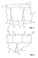
- FIG. 2 A section 7 of in FIG. 1 shown structure is in FIG. 2 shown enlarged.
- the joining zone 9, in which the functional element 3 is positively / positively locking and / or materially connected to the base body 1 is detected.
- the joining zone 9 is covered with the first layer 5, which in the various, in FIG. 2 Having zones bordered by dashed lines or areas of the first layer 5 has a different composition.
- the first layer 5 essentially comprises oxides and / or phosphates of the functional element 3.
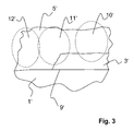
- FIG. 3 a further embodiment of a device according to the invention is shown, in which the functional element 3 'layered on the base body 1' is arranged and fixed thereto.
- the first layer 5 ' extends above the main body 1' and the layer-shaped functional element 3 '.
- three different regions 10', 11 'and 12' with different material composition can be identified analogously to the first embodiment.
- a device according to the invention in the form of an approximately 1.8 mm thick sheet of the magnesium alloy AZ 31 is welded overlapping with a 1.3 mm thick sheet of aluminum alloy AlMgSi1 by electron beam welding.
- both materials mix in the molten state. After solidification, there are three areas of different composition.
- the middle joining area is characterized by gradients in the distribution of aluminum and magnesium.
- the welded component is contacted with an aluminum wire and then plasma chemically oxidized in an electrolyte described in Example 1.
- an 8 ⁇ m thick layer is formed on the magnesium side and, on the aluminum side, an approximately 3 ⁇ m thick layer of oxides and phosphates of the respective base material.
- a mean layer thickness of about 5 ⁇ m is established with these process parameters. If a later application requires a higher layer thickness, a bath end tension of 280 V is given. The layer thicknesses then increase in each case by 2-3 microns.
- the device according to the invention coated in this way has a higher corrosion resistance under the action of a salt mist load than in the uncoated state.
- the for plasma-chemical Process typical porous surface structure provides good adhesion for subsequent surface treatments such as painting and bonding.
- a device according to the invention in the form of a spar of a supporting wing construction for aircraft consists of a titanium alloy TiA16V4, which is connected by means of laser welding with ribs made of magnesium alloy AZ 31.
- this material composite acquires surface properties which, on the one hand, leads to a higher corrosion resistance, and on the other hand also simplifies subsequent gluing and / or painting by omitting further pretreatment steps.
- This critical from the point of view of local element formation material combination - which is characterized by the conditions in the aircraft interior such as condensation, dew point, low air circulation at long service lives in the hangar, etc. - can be realized only by the inventive solution.
Abstract
Description
Die vorliegende Erfindung betrifft eine Vorrichtung, insbesondere für die medizinische Anwendung als Endoprothese, bevorzugt als intraluminale Endoprothese, mit einem Grundkörper, der zumindest teilweise aus einem metallischen Material besteht, und mit einem an dem Grundkörper befestigten Funktionselement, das zumindest in einem Teil seines Volumens eine verglichen mit dem Material des Grundkörpers verschiedene metallische Materialzusammensetzung aufweist, die vorzugsweise mindestens teilweise radioopakes und/oder röntgenopakes Material aufweist, sowie ein Verfahren zur Herstellung einer solchen Vorrichtung.The present invention relates to a device, in particular for medical use as an endoprosthesis, preferably as an intraluminal endoprosthesis, with a base body which consists at least partially of a metallic material, and with a functional element attached to the base body, which at least in a part of its volume compared with the material of the base body has different metallic material composition, which preferably at least partially radiopaque and / or radiopaque material, as well as a method for producing such a device.
Stents sind endovaskuläre Prothesen (Endoprothesen) oder Implantate, die zur Behandlung von Stenosen (Gefäßverengungen) eingesetzt werden können. Sie weisen einen Grundkörper in Form eines hohlzylinder- oder röhrenförmigen Grundgitters auf, das an beiden Längsenden der Röhren offen ist. Das röhrenförmige Grundgitter einer derartigen Endoprothese wird in das zu behandelnde Gefäß eingesetzt und dient dazu, das Gefäß zu stützen.Stents are endovascular prostheses (endoprostheses) or implants that can be used to treat stenoses (vasoconstriction). They have a base body in the form of a hollow cylindrical or tubular base grid, which is open at both longitudinal ends of the tubes. The tubular base grid of such an endoprosthesis is inserted into the vessel to be treated and serves to support the vessel.
Derartige Stents oder andere Endoprothesen sowie Vorrichtungen, die beispielsweise im Flugzeugbau eingesetzt werden, weisen in ihrem Grundkörper häufig metallische Materialien auf. Hierbei können die metallischen Materialien einen biodegradierbaren Werkstoff bilden, wobei auch polymere, biodegradierbare Materialien enthalten sein können.Such stents or other endoprostheses and devices which are used for example in aircraft, often have metallic materials in their base body. Here, the metallic materials may form a biodegradable material, wherein polymeric, biodegradable materials may be included.
Unter Biodegradation werden hydrolytische, enzymatische und andere stoffwechselbedingte Abbauprozesse im lebenden Organismus verstanden, die vor allem durch die mit der Endoprothese in Kontakt gelangenden Körperflüssigkeiten verursacht werden und zu einer allmählichen Auflösung zumindest großer Teile der Endoprothese führen. Synonym zu dem Begriff Biodegradation wird häufig der Begriff Biokorrosion verwendet. Der Begriff Bioresorption umfasst die anschließende Resorption der Abbauprodukte durch den lebenden Organismus.Biodegradation is understood to mean hydrolytic, enzymatic and other metabolism-related degradation processes in the living organism, which are primarily caused by the body fluids which come into contact with the endoprosthesis and lead to a gradual dissolution of at least large parts of the endoprosthesis. Synonymous with the term biodegradation, the term biocorrosion is often used. The term bioresorption covers the subsequent absorption of the degradation products by the living organism.
Für den Grundkörper biodegradierbarer Endoprothesen geeignete Werkstoffe (Grundmaterial) können auch aus mehreren Materialien bestehen. Beispiele für geeignete polymere Verbindungen sind Polymere aus der Gruppe Cellulose, Kollagen, Albumin, Casein, Polysaccharide (PSAC), Polylactid (PLA), Poly-L-Lactid (PLLA), Polyglykol (PGA), Poly-D,L-Lactid-co-glycolid (PDLLA-PGA), Polyhydroxybuttersäure (PHB), Polyhydroxyvaleriansäure (PHV), Polyalkylcarbonate, Polyorthoester, Polyethylenterephtalat (PET), Polymalonsäure (PML), Polyanhydride, Polyphosphazene, Polyaminosäuren und deren Copolymere sowie Hyaluronsäure. Die Polymere können je nach den gewünschten Eigenschaften in Reinform, in derivatisierter Form, in Form von Blends oder als Copolymere vorliegen. Metallische biodegradierbare Werkstoffe basieren auf Legierungen von Magnesium, Eisen, Zink und/oder Wolfram.For the basic body of biodegradable endoprostheses suitable materials (base material) may also consist of several materials. Examples of suitable polymeric compounds are polymers from the group of cellulose, collagen, albumin, casein, polysaccharides (PSAC), polylactide (PLA), poly-L-lactide (PLLA), polyglycol (PGA), poly-D, L-lactide co-glycolide (PDLLA-PGA), polyhydroxybutyric acid (PHB), polyhydroxyvaleric acid (PHV), polyalkylcarbonates, polyorthoesters, polyethylene terephthalate (PET), polymalonic acid (PML), polyanhydrides, polyphosphazenes, polyamino acids and their copolymers, and hyaluronic acid. Depending on the desired properties, the polymers may be present in pure form, in derivatized form, in the form of blends or as copolymers. Metallic biodegradable materials are based on alloys of magnesium, iron, zinc and / or tungsten.
Die vorliegende Erfindung bezieht sich auf Endoprothesen oder andere Vorrichtungen mit einem Grundkörper, dessen Material einen metallischen Werkstoff enthält. Hierbei kommen neben den genannten biodegradierbaren Materialien auch weitere metallische Werkstoffe in Frage.The present invention relates to endoprostheses or other devices having a base body whose material contains a metallic material. In addition to the biodegradable materials mentioned, other metallic materials are also suitable.
Die Ermittlung der Position eines Stents oder anderer Vorrichtungen geschieht häufig mittels bildgebender Verfahren, beispielsweise mittels einer Röntgenstrahleinrichtung. Aufgrund der kleinen Ordnungszahl und der geringen Dichte des biodegradierbaren Materials Magnesium und seiner Legierungen ist die Röntgensichtbarkeit der daraus gefertigten medizinischen Implantate sehr gering. Um diesen Nachteil zu beheben, ist es bekannt, medizinische Vorrichtungen mit Funktionselementen zu versehen, die zumindest in einem Teil ihres Volumens eine verglichen mit dem Material des Grundkörpers verschiedene Materialzusammensetzung aufweisen. Diese sogenannten Marker oder Funktionselemente enthalten insbesondere ein Material, das die Röntgenstrahlen und/oder andere elektromagnetische Strahlen stärker absorbiert (im Folgenden als röntgenopakes oder radioopakes Material bezeichnet) als das Material des Grundkörpers.The determination of the position of a stent or other devices is often done by means of imaging methods, for example by means of an X-ray device. Due to the small atomic number and the low density of the biodegradable material magnesium and its alloys, the radiopacity of the medical implants made from it is very low. In order to remedy this disadvantage, it is known to provide medical devices with functional elements which, at least in part of their volume, have a different material composition compared to the material of the basic body. In particular, these so-called markers or functional elements contain a material which more strongly absorbs the x-rays and / or other electromagnetic radiation (hereinafter referred to as radiopaque or radiopaque material) than the material of the basic body.
In der Druckschrift
In der Druckschrift
Die Druckschrift
Auch hinsichtlich anderer Anwendungen einer oben angegebenen Vorrichtung, beispielsweise für die Anwendung in Flugzeugen, ist es üblich, verschiedene metallische Materialien miteinander zu kombinieren.Also with regard to other applications of a device mentioned above, for example for use in aircraft, it is common to combine different metallic materials together.
Bei Stents oder anderen Vorrichtungen, deren Grundkörper aus einem metallischen Material bestehen, ergibt sich bei der Anordnung von metallischen Funktionselementen an dem Grundkörper das Problem, dass an dem Kontaktbereich zwischen dem Material des Grundkörpers und dem Material des Funktionselements eine Kontaktkorrosion auftritt. Diese führt zur Zerstörung der Vorrichtung bzw. zur Abtrennung des Funktionselements von dem Grundkörper, so dass die Vorrichtung nicht mehr in der Lage ist, ihre Funktion zu erfüllen, bzw. nicht mehr aufgefunden werden kann. Für das geschilderte Problem enthalten die oben beschriebenen Vorrichtungen aus dem Stand der Technik keine Lösung.In the case of stents or other devices whose basic body consists of a metallic material, the problem arises in the arrangement of metallic functional elements on the basic body that contact corrosion occurs at the contact area between the material of the basic body and the material of the functional element. This leads to the destruction of the device or to the separation of the functional element of the main body, so that the device is no longer able to fulfill their function, or can no longer be found. For the described problem, the devices of the prior art described above contain no solution.
Es ist bekannt, die beschleunigte Korrosion von Implantaten aus Magnesiumlegierungen mit Röntgenmarken durch Komplettbeschichtungen mit polymeren Überzügen zu unterbinden. Dabei kommen sowohl biodegradierbare als auch nichtdegradierbare Polymere zum Einsatz. Ebenfalls denkbar sind Lösungen, in denen der Bereich, in dem sich Röntgenmarker befinden, nur über einen Teil des Grundkörpers vor einem beschleunigten Korrosionsangriff geschützt werden, zum Beispiel durch Tauchen in eine Polymerlösung. Die so beschichteten Implantate zeigen zwar zunächst ein verzögertes Degradationsverhalten, korrodieren allerdings im Moment der Beschädigung des polymeren Überzugs in der gleichen Weise wie ein ungeschütztes Implantat. Eine andere prinzipielle Möglichkeit besteht in der Einbringung von gefüllten Polymeren in die dafür im Implantat vorgesehenen Aussparungen. Der Füllstoff dieser Polymere besteht aus feinen Partikeln von röntgenopaken Elementen. Durch die polymere Umhüllung wird eine Minimierung der realen Kontaktfläche des Markermaterials mit dem Magnesium erreicht und die Lokalelementbindung unterdrückt. Allerdings sind die vom Magnesium-implantat auf den Röntgenmarker ausgeübte Haltekräfte aufgrund der geringen Festigkeit des Polymers und der Unterschiede in den E-Modulen der beiden Werkstoffe begrenzt. Dies führt nach bereits wenigen Tagen zu einem Verlust der Verbundfestigkeit und zu einer damit verbunden Gefahr des Herauslösens des Röntgenmarkers aus dem Implantat.It is known to inhibit accelerated corrosion of X-ray brand magnesium alloy implants by complete coating with polymeric coatings. Both biodegradable and non-degradable polymers are used. Also conceivable are solutions in which the area in which X-ray markers are located is protected from accelerated corrosive attack over only a portion of the body, for example by immersion in a polymer solution. Although the implants coated in this way initially show a delayed degradation behavior, they corrode at the moment of damage to the polymeric coating in the same way as an unprotected implant. Another principal possibility is the introduction of filled polymers into the recesses provided for this purpose in the implant. The filler of these polymers consists of fine particles of radiopaque elements. The polymeric sheath minimizes the real contact area of the marker material with the magnesium and suppresses local element bonding. However, the holding forces exerted by the magnesium implant on the x-ray marker are limited due to the low strength of the polymer and the differences in the moduli of elasticity of the two materials. This leads after only a few days to a loss of bond strength and an associated risk of detachment of the X-ray marker from the implant.
Die Aufgabe der vorliegenden Erfindung besteht somit darin, eine Vorrichtung zu schaffen, bei der der direkte metallische Kontakt des Funktionselements zum Grundkörper reduziert und gleichzeitig eine hohe Verbundfestigkeit erzielt wird. Die Aufgabe besteht ferner darin, ein kostengünstiges Verfahren zur Herstellung einer derartigen Vorrichtung anzugeben.The object of the present invention is therefore to provide a device in which the direct metallic contact of the functional element to the base body is reduced and at the same time a high bond strength is achieved. The object is also to provide a cost-effective method for producing such a device.
Die obige Aufgabe wird durch eine Vorrichtung gelöst, die zumindest auf- und/oder in dem an die Oberfläche reichenden Grenzbereich zwischen Grundkörper und Funktionselement eine auf den Grundkörper auf- und/oder eingebrachte erste Schicht aufweist, welche
- a) mittels plasmachemischer Behandlung in einer wässrigen Lösung hergestellt ist, die Phosphationen enthält, oder
- b) Magnesiumstearat aufweist.
- a) is prepared by plasma chemical treatment in an aqueous solution containing phosphate ions, or
- b) comprises magnesium stearate.
Eine derartige erfindungsgemäße Vorrichtung hat den Vorteil, dass der direkte metallische Kontakt zwischen Funktionselement und Grundkörper reduziert und gleichzeitig eine hohe Verbundfestigkeit erzielt wird. Hierdurch wird die Degradationsdauer einer derartigen Vorrichtung wesentlich verlängert und der Verbleib des Funktionselements an der Vorrichtung auch bei fortgeschrittener Degradation sicher gestellt.Such a device according to the invention has the advantage that the direct metallic contact between the functional element and the base body is reduced and at the same time a high bond strength is achieved. As a result, the degradation of such a device is significantly extended and the whereabouts of the functional element on the device even with advanced degradation ensured.
In einem bevorzugten Ausführungsbeispiel weist der Grundkörper mindestens ein zumindest weitestgehend biodegradierbares metallisches Material, vorzugsweise Magnesium oder eine Magnesiumlegierung, auf.In a preferred embodiment, the base body has at least one at least largely biodegradable metallic material, preferably magnesium or a magnesium alloy.
In einem weiteren bevorzugten Ausführungsbeispiel beträgt die Dicke der mittels der plasmachemischen Behandlung auf der Grundkörperoberfläche hergestellten ersten Schicht etwa 1 µm bis etwa 20 µm, vorzugsweise etwa 2 µm bis etwa 8 µm.In a further preferred embodiment, the thickness of the first layer produced on the base body surface by means of the plasma-chemical treatment is about 1 μm to about 20 μm, preferably about 2 μm to about 8 μm.
In einem weiteren bevorzugten Ausführungsbeispiel ist zumindest in dem an der Oberfläche zugänglichen Grenzbereich zwischen Grundkörper und Funktionselement auf der ersten Schicht eine zweite Schicht mit mindestens einem Polymer aus der Gruppe enthaltend Parylene, Polyurethan und Magnesiumstearat angeordnet.In a further preferred embodiment, a second layer with at least one polymer from the group comprising parylene, polyurethane and magnesium stearate is arranged on the first layer at least in the border region accessible between the base body and the functional element.
Hierbei werden als Parylene vollständig lineare, teilkristalline und unvernetzte aromatische Polymere bezeichnet. Diese Polymere lassen sich je nach ihrem Aufbau in vier verschiedene Grundtypen einteilen, nämlich Parylene C, Parylene D, Parylene N und Parylene F. Parylene kann auf das Funktionselement bevorzugt mittels eines Aufdampfprozesses aufgebracht werden.Here are referred to as parylene completely linear, semi-crystalline and uncrosslinked aromatic polymers. Depending on their structure, these polymers can be divided into four basic types, namely Parylene C, Parylene D, Parylene N and Parylene F. Parylene can preferably be applied to the functional element by means of a vapor deposition process.
Das Funktionselement weist vorzugsweise eine oder mehrere röntgen- und/oder radioopake Elemente oder Verbindungen aus der Gruppe bestehend aus Platin, Iridium, Gold, Wolfram, Molybdän, Niob, Tantal, Yttrium, Zirkonium, Ytterbium oder Legierungen aus diesen Metallen auf.The functional element preferably comprises one or more X-ray and / or radio-opaque elements or compounds from the group consisting of platinum, iridium, gold, tungsten, molybdenum, niobium, tantalum, yttrium, zirconium, ytterbium or alloys of these metals.
In einem weiteren bevorzugten Ausführungsbeispiel weist die zweite Schicht eine Schichtdicke zwischen etwa 0,5 µm und etwa 5 µm auf.In a further preferred embodiment, the second layer has a layer thickness between about 0.5 μm and about 5 μm.
Die obige Aufgabe wird ferner durch ein Verfahren zur Herstellung einer derartigen Vorrichtung gelöst, mit den folgenden Schritten:
- i.) Befestigen eines Funktionselements an dem Grundkörper, das zumindest in einem Teil seines Volumens eine verglichen mit dem Material des Grundkörpers verschiedene metallische Materialzusammensetzung aufweist, die vorzugsweise mindestens teilweise radioopakes und/oder röntgenopakes Material beinhaltet,
- i.a) plasmachemische Behandlung des Grundkörpers mit Funktionselement in einer wässrigen Lösung, die Phosphationen enthält, zur Erzeugung einer ersten Schicht auf mindestens dem Teil der Körperoberfläche der den an die Oberfläche reichenden Grenzbereich zwischen Grundkörper und Funktionselement aufweist/bildet, oder
- ii.b) Aufbringen einer ersten Schicht, welche Magnesiumstearat enthält, auf mindestens den Teil der Körperoberfläche, der den an die Oberfläche reichenden Grenzbereich zwischen Grundkörper und Funktionselement aufweist/bildet.
- i.) attaching a functional element to the base body which, at least in part of its volume, has a different metallic material composition than the material of the base body, which preferably comprises at least partially radioopaque and / or radiopaque material,
- ia) plasma-chemical treatment of the base body with functional element in an aqueous solution containing phosphate ions, to produce a first layer on at least the part of the body surface which has / reaches the surface reaching between the base body and the functional element, or
- ii.b) applying a first layer, which contains magnesium stearate, on at least the part of the body surface, which / has the reaching to the surface boundary region between the base body and functional element /.
Das erfindungsgemäße Verfahren stellt ein kostengünstiges Verfahren zur Herstellung einer Vorrichtung mit obigen Vorteilen dar.The method according to the invention represents a cost-effective method for producing a device with the above advantages.
In einem bevorzugten Ausführungsbeispiel wird die erste Schicht nach der plasmachemischen Behandlung in einem Lösungsmittel, vorzugsweise mittels destilliertem H2O gespült und anschließend vorzugsweise bei einer Temperatur von mindestens 80°C, besonders bevorzugt mindestens etwa 100°C getrocknet, wobei das Trocknen vorzugsweise in einem Umluftofen durchgeführt wird.In a preferred embodiment, the first layer after the plasma-chemical treatment is rinsed in a solvent, preferably by means of distilled H 2 O and then dried preferably at a temperature of at least 80 ° C, more preferably at least about 100 ° C, wherein the drying preferably in a Convection oven is performed.
In einem bevorzugten Ausführungsbeispiel ist in der wässrigen Lösung ein Puffer, vorzugsweise Kaliumdihydrogenphosphat und/oder Natriumdihydrogenphosphat enthalten. Alternativ oder zusätzlich kann in der wässrigen Lösung auch Calciumdihydrogenphosphat als Puffer enthalten sein, dessen geringe Wasserlöslichkeit durch die Zugabe von Komplexbildnern wie Ethylendiamin erhöht werden kann.In a preferred embodiment, the aqueous solution contains a buffer, preferably potassium dihydrogen phosphate and / or sodium dihydrogen phosphate. Alternatively or additionally, calcium dihydrogen phosphate can also be contained in the aqueous solution as a buffer, the low water solubility of which can be increased by the addition of complexing agents, such as ethylenediamine.
In einem bevorzugten Ausführungsbeispiel des erfindungsgemäßen Verfahrens erfolgt die plasmachemische Behandlung der Körperoberfläche dadurch, dass an den Grundkörper eine gepulste Spannung angelegt wird, deren Amplitude in einem Teil des Behandlungszeitraums eine für das Material des Funktionselement charakteristische Badspannung übersteigt und vorzugsweise im Verlauf der Behandlung ansteigt.In a preferred embodiment of the method according to the invention, the plasma-chemical treatment of the body surface takes place in that a pulsed voltage is applied to the main body, whose amplitude is in a part of the treatment period exceeds a characteristic of the material of the functional element bath voltage and preferably increases in the course of treatment.
In einem bevorzugten Ausführungsbeispiel wird das Funktionselement mittels Pressen, Nieten, Laserschweißen und/oder Elektronenstrahlschweißen an dem Grundkörper befestigt.In a preferred embodiment, the functional element is attached to the base body by means of pressing, riveting, laser welding and / or electron beam welding.
In einem bevorzugten Ausführungsbeispiel beträgt die Stromdichte bei der plasmachemischen Behandlung mindestens etwa 8 mA/cm2.In a preferred embodiment, the current density in the plasma-chemical treatment is at least about 8 mA / cm 2 .
Die erfindungsgemäße Vorrichtung weist ein Schichtsystem, insbesondere auf einem absorbierbaren Magnesium-Implantat auf, das mit als Röntgenmarker wirkenden Funktionselementen aus Wolfram, Tantal, Molybdän, Niob und Zirkon sowie deren Legierungen ausgestattet ist. Dabei wird zunächst der Röntgenmarker mittels bekannter Technologien wie Einpressen, Nieten, Laser- oder Elektronenstrahlschweißen mit dem Grundkörper verbunden. Anschließend erfolgt eine anodische Kontaktierung dieses nunmehr aus einem Verbundwerkstoff bestehenden Bauteils (Vorrichtung). Der Kontaktierungswerkstoff besteht dabei aus einem Aluminium- oder Titan-Draht. Anschließend erfolgt ein Eintauchen in eine wässrige, phosphathaltige Lösung. Nach Anlegen einer gepulsten, stetig steigenden Badspannung, die sich durch lange Pulspausen auszeichnet, kommt es zur Oxidation des Werkstoffs des Grundkörpers und des Funktionselements. Durch die unterschiedlichen elektrochemischen Eigenschaften der Legierung des Grundkörpers einerseits und des Funktionselements andererseits bilden sich auf der Oberfläche beider Elemente unterschiedlich dicke Oxidschichten. An der unmittelbaren Kontaktstelle des Materials des Grundkörpers und des Materials des Funktionselements entsteht eine Grenzfläche zwischen den Oxiden des Grundmaterials und den Oxiden des Funktionselements, das beispielsweise in Form eines Röntgenmarkers vorliegt. Durch die Oxidschichtbildung auf der Oberfläche wird der die Korrosion fördernde unmittelbare Kontakt zwischen dem Material des Grundkörpers und dem Material des Funktionselements auf den innen liegenden Bereich (Innenseite) und somit unter die Oberfläche der Vorrichtung verlagert. Mit weiter steigender Badspannung sind zunächst an der Oberfläche des Grundkörpers, welche vorzugsweise Magnesium aufweist, plasmachemische Effekte zu beobachten, die eine Mischphase aus Oxiden und Phosphaten des Materials des Grundkörpers entstehen lassen. Zur gleichen Zeit wächst die Oxidschicht auf dem Funktionselement weiter. Bei einer für das Material des Funktionselements charakteristischen Badspannung von beispielsweise ca. 230 V für Tantal oder 260 V für Wolfram geht eine durch plasmachemische Effekt bedingte Umwandlung der ursprünglich reinen plasmachemisch erzeugten Oxidschicht in eine Phosphat-/Oxidmischschicht der Funktionselement-Oberfläche vonstatten. Die Dicke der Oxid-/Phosphatmischschicht auf der Funktionselement-Oberfläche wächst dabei abhängig von der Badspannung. Aufgrund der bereits erwähnten unterschiedlichen elektrochemischen Eigenschaften und der damit verbundenen unterschiedlich hohen Sauerstoffaffinität von Grundkörper und Funktionselement muss der plasmachemische Prozess unter anderen Bedingungen ablaufen als die Beschichtung der einzelnen Komponenten. Es ist vor allem von Vorteil, wenn die jeweiligen Oxidschichten langsam wachsen, da andernfalls das Oxid mit der höchsten Bildungsenthalpie keine kohärente Schicht ausbilden kann. Das langsame Wachstum der Oxidschicht wird erfindungsgemäß durch lange Pausen zwischen den Spannungspulsen erreicht. Diese können bis zu 500 Millisekunden lang sein. Dies führt zu einer Rekombination der durch die plasmachemischen Effekte hervorgerufenen Ungleichmäßigkeiten in den Phosphat- und Oxidschichten der Metalle von Grundkörper und Funktionselement.The device according to the invention has a layer system, in particular on an absorbable magnesium implant, which is equipped with functioning as an X-ray marker functional elements of tungsten, tantalum, molybdenum, niobium and zirconium and their alloys. Initially, the X-ray marker is connected to the base body by known technologies such as press-fitting, riveting, laser or electron beam welding. This is followed by an anodic contacting of this now consisting of a composite component (device). The contacting material consists of an aluminum or titanium wire. This is followed by immersion in an aqueous, phosphate-containing solution. After applying a pulsed, steadily increasing bath voltage, which is characterized by long pulse pauses, it comes to the oxidation of the material of the main body and the functional element. Due to the different electrochemical properties of the alloy of the main body on the one hand and the functional element on the other hand, oxide layers of different thickness are formed on the surface of both elements. At the immediate contact point of the material of the base body and the material of the functional element, an interface between the oxides of the base material and the oxides of the functional element, which is present for example in the form of an X-ray marker. Due to the oxide layer formation on the surface, the corrosion-promoting direct contact between the material of the base body and the material of the functional element is displaced to the inner area (inner side) and thus below the surface of the device. As the bath voltage continues to rise, plasma-chemical effects are initially observed on the surface of the main body, which preferably contains magnesium, which cause a mixed phase of oxides and phosphates of the material of the main body. At the same time, the oxide layer continues to grow on the functional element. At one for the material of the Functional characteristic bath voltage of, for example, about 230 V for tantalum or 260 V for tungsten is due to a plasmachemic effect conversion of originally pure plasma-chemically generated oxide layer in a phosphate / oxide mixture layer of the functional element surface. The thickness of the oxide / phosphate mixture layer on the functional element surface increases depending on the bath voltage. Due to the already mentioned different electrochemical properties and the associated different high oxygen affinity of the base body and the functional element, the plasma-chemical process must proceed under different conditions than the coating of the individual components. It is particularly advantageous if the respective oxide layers grow slowly, otherwise the oxide with the highest formation enthalpy can not form a coherent layer. The slow growth of the oxide layer is achieved according to the invention by long pauses between the voltage pulses. These can be up to 500 milliseconds long. This leads to a recombination of the irregularities in the phosphate and oxide layers of the base body and the functional element caused by the plasma-chemical effects.
An der Oberfläche und - je nach Höhe der angelegten Badspannung - bis in eine Tiefe von ca. 10 µm der Grenzfläche zwischen Grundkörper und Funktionselement wird erfindungsgemäß ein gleichmäßiger Übergang der Zusammensetzung erzielt. Durch die plasmachemischen Effekte, die bei höheren Badspannungen sowohl das Material des Grundkörpers als auch das des Funktionselements aufschmelzen und teilweise in die Dampfphase versetzen, erfolgt sowohl eine Durchmischung der Materialien von Grundkörper und Funktionselement als auch eine Durchmischung der entsprechenden Oxide und Phosphate im Bereich der ersten Schicht. Durch das in der wässrigen Lösung (Elektrolyt) des erfindungsgemäßen Verfahrens vorhandene große Sauerstoff- und Phosphorangebot werden in der kurzzeitig stabilen Plasmaphase auch Mischoxide wie zum Beispiel Magnesium-Tantaloxid und Mischphosphate des Materials des Grundkörpers und des Funktionselements gebildet. Diese danach in der Übergangszone (Grenzbereich von Grundkörper und Funktionselement, die sich bis an die Oberfläche der unbehandelten Vorrichtung erstreckt) vorhandenen Verbindungen bilden eine Trennschicht und reduzieren damit den unmittelbaren metallischen Kontakt beider Partner auf Bereiche im Bauteilinneren. Die geringere Korrosionsbeständigkeit dieser innen liegenden Bereiche wirkt sich erst dann aus und beschleunigt entsprechend die Korrosion, wenn die darüberliegenden Oxid- und Phosphatschichten bei Auslagerung unter korrosiven Bedingungen degradiert sind.On the surface and - depending on the level of the applied bath voltage - to a depth of about 10 microns of the interface between the body and functional element, a uniform transition of the composition is achieved according to the invention. Due to the plasma-chemical effects, which both melt the material of the main body and the functional element at higher bath voltages and partially put into the vapor phase, both a thorough mixing of the materials of the body and functional element as well as a thorough mixing of the corresponding oxides and phosphates in the first Layer. By virtue of the large oxygen and phosphorus supply present in the aqueous solution (electrolyte) of the process according to the invention, mixed oxides such as, for example, magnesium tantalum oxide and mixed phosphates of the material of the main body and of the functional element are also formed in the short-term stable plasma phase. These then present in the transition zone (boundary region of the base body and functional element, which extends to the surface of the untreated device) form a separating layer and thus reduce the direct metallic contact of both partners on areas inside the component. The lower corrosion resistance of these internal areas only then affects and accelerates accordingly Corrosion when the overlying oxide and phosphate layers are degraded during aging under corrosive conditions.
Alternativ zu einer Beschichtung mittels plasmachemischem Verfahren kann der Grundkörper mit Funktionselement in dem Grenzbereich auch ohne vorangegangenes plasmachemisches Oxidationsverfahren mit Magnesiumstearat beschichtet werden.As an alternative to a coating by means of a plasma-chemical process, the base body with functional element in the boundary region can also be coated with magnesium stearate without a preceding plasma-chemical oxidation process.
Die erfindungsgemäße Oberflächenschicht kann auch als Basisschicht für eine nachfolgende Parylene enthaltende Schicht dienen. Bei einer solchen Schichtkombination wird die Degradationszeit der Vorrichtung nochmals wesentlich erhöht.The surface layer according to the invention can also serve as a base layer for a subsequent parylene-containing layer. With such a layer combination, the degradation time of the device is again significantly increased.
Zusätzlich kann der Bereich um das Funktionselement oder die gesamte Vorrichtung mit einem Polymer (Parylene, Polyurethan, Magnesiumstearat) beschichtet werden.In addition, the area around the functional element or the entire device can be coated with a polymer (parylene, polyurethane, magnesium stearate).
Weitere Vorteile sind:
- Es werden Vollmarker verwendet, welche eine hohe Röntgendichte aufweisen (vergleiche Stand der Technik mit im Polymer suspendiertem Material).
- Es wird eine stoffschlüssige oder formschlüssige (Pressen/Nieten) Verbindung zwischen dem Grundkörper und dem Material des Funktionselements ohne Zugabe eines dritten Werkstoffs (wie Polymere oder Klebstoffe) realisiert.
- Es wird ein direkter Metall/Metall-Kontakt von Grundkörper und Funktionselement an der Oberfläche der Vorrichtung vermieden. Hierdurch wird dort die Bildung eines Lokalelements verhindert und die Korrosion gehemmt.
- Beide Metalle werden in einem Prozessschritt passiviert. Eine Montage vorher unterschiedlich behandelter Komponenten und die damit einhergehende Gefahr von Beschädigungen der Oberflächenschicht entfällt.
- Die Breite des technologisch bedingten Spaltes zwischen Funktionselement und Grundkörper wird verringert. Hierdurch verringert sich die Gefahr der Adhäsion von Fremdpartikeln.
- Das erfindungsgemäße Verfahren erzeugt auf beiden Metallen eine verfahrensbedingte poröse Struktur, die eine nachträgliche Versiegelung des Bauteils, z.B. mit polymeren Deckschichten, durch eine bessere Haftung vereinfacht oder als Carrier/Träger (bspw. für eine pharmazeutisch aktive Substanz oder andere funktionelle Stoffe) genutzt werden kann. Hierbei wird unter einer "pharmazeutisch aktiven Substanz" (oder therapeutisch aktive oder wirksame Substanz) ein pflanzlicher, tierischer oder synthetischer Wirkstoff (Medikament) oder ein Hormon verstanden, das in geeigneter Dosierung als Therapeutikum zur Beeinflussung von Zuständen oder Funktionen des Körpers, als Ersatz für natürlich vom Menschen oder tierischen Körper erzeugte Wirkstoffe, wie Insulin, sowie zur Beseitigung oder Unschädlichmachen von Krankheitserregern, Tumoren, Krebszellen oder Körperfremdstoffen Einsatz findet.
- Ferner besteht die Möglichkeit der Beladung der Oberfläche des Funktionselements mit Trägern einer pharmazeutisch aktiven Substanz. Die pharmazeutisch aktiven Substanzen können aufgrund der zum Grundkörper verschiedenen chemischen Zusammensetzung eine andere Freisetzungskinetik entfalten.
- Vorrichtungen aus unterschiedlichen Leichtmetallen und deren Legierungen können nach dem Fügen mittels stoff-, kraft- oder formschlüssiger Prinzipien mit einer Oberflächentechnologie behandelt werden. Hierdurch wird der Einfluss unterschiedlicher Oberflächeneigenschaften verringert, welche bisher eine Einzelbehandlung der Bauteile der Vorrichtung vor dem Zusammensetzen erforderte.
- Die Bildung von Mischoxiden, Mischphosphaten und einfachen Oxiden in der Oberfläche an dem Grenzbereich zwischen Grundkörper und Funktionselement führt zu einer Erhöhung der Korrosionsbeständigkeit dieser sonst aus korrosionstechnischer Schicht kritischen Oberflächenbereiche.
- Full markers are used which have a high radiopacity (compare prior art with material suspended in the polymer).
- It is realized a cohesive or positive (pressing / riveting) connection between the base body and the material of the functional element without the addition of a third material (such as polymers or adhesives).
- It prevents a direct metal / metal contact of the body and functional element on the surface of the device. As a result, there the formation of a local element is prevented and inhibited corrosion.
- Both metals are passivated in one process step. An assembly previously differently treated components and the associated risk of damage to the surface layer is eliminated.
- The width of the technologically related gap between the functional element and the base body is reduced. This reduces the risk of adhesion of foreign particles.
- The process according to the invention produces a process-related porous structure on both metals, which can facilitate a subsequent sealing of the component, eg with polymeric cover layers, by better adhesion or can be used as a carrier / carrier (for example for a pharmaceutically active substance or other functional substances) , Here, a "pharmaceutically active substance" (or therapeutically active or active substance) is a plant, animal or synthetic drug (medicament) or a hormone, in a suitable dosage as a therapeutic agent for influencing conditions or functions of the body, as a substitute for naturally produced by humans or animal body agents, such as insulin, as well as for eliminating or rendering harmless pathogens, tumors , Cancer cells or body alien substances finds use.
- Furthermore, there is the possibility of loading the surface of the functional element with carriers of a pharmaceutically active substance. The pharmaceutically active substances can develop a different release kinetics due to the chemical composition different from the basic body.
- Devices made of different light metals and their alloys can be treated after joining by means of material, force or positive principles with a surface technology. As a result, the influence of different surface properties is reduced, which previously required a single treatment of the components of the device prior to assembly.
- The formation of mixed oxides, mixed phosphates and simple oxides in the surface at the boundary region between the main body and functional element leads to an increase in the corrosion resistance of this otherwise critical corrosion surface layer surface areas.
Die Erfindung wird nachfolgend anhand von in Figuren dargestellten Ausführungsbeispielen näher erläutert. Dabei bilden alle beschriebenen und/oder bildlich dargestellten Merkmale den Gegenstand der Erfindung, unabhängig von ihrer Zusammenfassung in den Ansprüchen oder deren Rückbeziehung.The invention will be explained in more detail with reference to embodiments shown in FIGS. All described and / or illustrated features form the subject matter of the invention, regardless of their combination in the claims or their dependency.
Es zeigen schematisch:
- Fig. 1
- einen Querschnitt durch ein erstes Ausführungsbeispiel einer erfindungsgemäßen Vorrichtung,
- Fig. 2
- einen vergrößerten Ausschnitt aus
Figur 1 und - Fig. 3
- einen Querschnitt durch ein zweites Ausführungsbeispiel einer erfindungsgemäßen Vorrichtung.
- Fig. 1
- a cross section through a first embodiment of a device according to the invention,
- Fig. 2
- an enlarged section
FIG. 1 and - Fig. 3
- a cross section through a second embodiment of a device according to the invention.
Der in
- 80 g KH2PO4
- 45 g Na2CO3
- 65 ml ED (99%)
- 5g bis 10 g NaOH
Bei Badendspannungen von 200 bis 500 V und unter Verwendung von gepulsten Strömen mit
- 80 g of KH 2 PO 4
- 45 g of Na 2 CO 3
- 65 ml of ED (99%)
- 5g to 10g NaOH
At bath end voltages of 200 to 500 V and using pulsed currents with a duty cycle of 5 ms on and 100 ms off (in extreme cases up to 500 milliseconds off) and a current density of 100 mA / cm 2 , a first layer is formed on the
Ein Ausschnitt 7 der in
In
Eine erfindungsgemäße Vorrichtung in Form eines ca. 1,8 mm dicken Blechs aus der Magnesiumlegierung AZ 31 wird mit einem 1,3 mm dicken Blech der Aluminiumlegierung AlMgSi1 mittels Elektronenstrahlschweißverfahren überlappend verschweißt. In der Fügezone vermischen sich beide Materialien im schmelzflüssigen Zustand. Nach der Erstarrung liegen damit drei Bereiche unterschiedlicher Zusammensetzung vor. Der mittlere Fügebereich zeichnet sich dabei durch Gradienten in der Verteilung des Aluminiums und des Magnesiums aus. Es erfolgt ein nachfolgendes mechanisches Überschleifen der Fügezone und eine Reinigung bzw. Entfettung in einem wässrigen und ca. 60°C heißen Entfettungsbad. Nach zwei kurzen Spülvorgängen in destilliertem Wasser wird das geschweißte Bauteil mit einem Aluminiumdraht kontaktiert und in einem in Beispiel 1 beschriebenen Elektrolyt anschließend plasmachemisch oxidiert. Nach Erreichen einer Badendspannung von ca. 260 V bildet sich auf der Magnesiumseite eine 8 µm dicke und auf der Aluminiumseite eine ca. 3 µm dicke Schicht aus Oxiden und Phosphaten des jeweiligen Grundmaterials aus. In der Fügezone stellt sich bei diesen Verfahrensparametern eine mittlere Schichtdicke von ca. 5 µm ein. Falls eine spätere Anwendung eine höhere Schichtdicke erforderlich macht, wird eine Badendspannung von 280 V vorgegeben. Die Schichtdicken erhöhen sich dann jeweils um 2-3 µm. Die auf diese Art beschichtete erfindungsgemäße Vorrichtung weist unter Einwirkung einer Salznebelbelastung einen höheren Korrosionswiderstand als im unbeschichteten Zustand auf. Die für plasmachemische Verfahren typische poröse Oberflächenstruktur sorgt für eine gute Adhäsion für nachfolgende Oberflächenbehandlungen wie Lackieren und Verkleben.A device according to the invention in the form of an approximately 1.8 mm thick sheet of the magnesium alloy AZ 31 is welded overlapping with a 1.3 mm thick sheet of aluminum alloy AlMgSi1 by electron beam welding. In the joining zone, both materials mix in the molten state. After solidification, there are three areas of different composition. The middle joining area is characterized by gradients in the distribution of aluminum and magnesium. There is a subsequent mechanical grinding of the joining zone and a cleaning or degreasing in an aqueous and about 60 ° C hot degreasing. After two brief rinses in distilled water, the welded component is contacted with an aluminum wire and then plasma chemically oxidized in an electrolyte described in Example 1. After reaching a bath end tension of about 260 V, an 8 μm thick layer is formed on the magnesium side and, on the aluminum side, an approximately 3 μm thick layer of oxides and phosphates of the respective base material. In the joining zone, a mean layer thickness of about 5 μm is established with these process parameters. If a later application requires a higher layer thickness, a bath end tension of 280 V is given. The layer thicknesses then increase in each case by 2-3 microns. The device according to the invention coated in this way has a higher corrosion resistance under the action of a salt mist load than in the uncoated state. The for plasma-chemical Process typical porous surface structure provides good adhesion for subsequent surface treatments such as painting and bonding.
Eine erfindungsgemäße Vorrichtung in Form eines Holmes einer tragenden Flügelkonstruktion für Luftfahrzeuge besteht aus einer Titanlegierung TiA16V4, die mittels Laserschweißen mit Spanten aus der Magnesiumknetlegierung AZ 31 verbunden wird. Durch die in Beispiel 1 beschriebene prinzipielle Verfahrensprozedur und den dort verwendeten Elektrolyt erlangt dieser Werkstoffverbund Oberflächeneigenschaften, die einerseits zu einer höheren Korrosionsbeständigkeit führt, andererseits auch ein nachfolgendes Verkleben und/oder Lackieren durch den Wegfall weiterer Vorbehandlungsschritte vereinfacht. Diese aus der Sicht einer Lokalelementbildung kritische Werkstoffkombination - die durch die Bedingungen im Flugzeuginneren wie Schwitzwasser, Taupunktunterschreitung, geringe Luftumwälzung bei langen Standzeiten im Hangar usw. gekennzeichnet ist - kann erst durch die erfindungsgemäße Lösung realisiert werden.A device according to the invention in the form of a spar of a supporting wing construction for aircraft consists of a titanium alloy TiA16V4, which is connected by means of laser welding with ribs made of magnesium alloy AZ 31. As a result of the basic process procedure described in Example 1 and the electrolyte used there, this material composite acquires surface properties which, on the one hand, leads to a higher corrosion resistance, and on the other hand also simplifies subsequent gluing and / or painting by omitting further pretreatment steps. This critical from the point of view of local element formation material combination - which is characterized by the conditions in the aircraft interior such as condensation, dew point, low air circulation at long service lives in the hangar, etc. - can be realized only by the inventive solution.
- 1, 1'1, 1 '
- Grundkörper der erfindungsgemäßen VorrichtungBasic body of the device according to the invention
- 3, 3'3, 3 '
- Funktionselementfunctional element
- 5, 5'5, 5 '
- erste Schichtfirst shift
- 77
- Ausschnittneckline
- 9, 9'9, 9 '
-
Übergangsbereich (Fügezone) zwischen Grundkörper 1 bzw. 1' und Funktionselement 3 bzw. 3'Transition region (joining zone) between
main body 1 or 1 'andfunctional element 3 or 3' - 10, 10'10, 10 '
-
Bereich der ersten Schicht 5 bzw. 5' mit Oxiden und/oder Phosphaten des Grundkörper-MaterialsArea of the
first layer 5 or 5 'with oxides and / or phosphates of the main body material - 11, 11'11, 11 '
-
Bereich der ersten Schicht 5 bzw. 5' mit Oxiden und/oder Phosphaten des Grundkörper-Materials und des Funktionselement-MaterialsArea of the
first layer 5 or 5 'with oxides and / or phosphates of the main body material and the functional element material - 12, 12'12, 12 '
-
Bereich der ersten Schicht 5 bzw. 5' mit Oxiden und/oder Phosphaten des Funktionselement-MaterialsArea of the
first layer 5 or 5 'with oxides and / or phosphates of the functional element material
Claims (12)
Applications Claiming Priority (1)
| Application Number | Priority Date | Filing Date | Title |
|---|---|---|---|
| DE200810054845 DE102008054845A1 (en) | 2008-12-18 | 2008-12-18 | Device and method for producing the same |
Publications (3)
| Publication Number | Publication Date |
|---|---|
| EP2198899A2 true EP2198899A2 (en) | 2010-06-23 |
| EP2198899A3 EP2198899A3 (en) | 2013-10-23 |
| EP2198899B1 EP2198899B1 (en) | 2015-10-07 |
Family
ID=42102672
Family Applications (1)
| Application Number | Title | Priority Date | Filing Date |
|---|---|---|---|
| EP09177440.6A Not-in-force EP2198899B1 (en) | 2008-12-18 | 2009-11-30 | Device and method for producing same |
Country Status (3)
| Country | Link |
|---|---|
| US (1) | US8992596B2 (en) |
| EP (1) | EP2198899B1 (en) |
| DE (1) | DE102008054845A1 (en) |
Cited By (1)
| Publication number | Priority date | Publication date | Assignee | Title |
|---|---|---|---|---|
| EP2399619A3 (en) * | 2010-06-25 | 2014-08-27 | Biotronik AG | Implant and Method for Manufacturing Same |
Families Citing this family (6)
| Publication number | Priority date | Publication date | Assignee | Title |
|---|---|---|---|---|
| DE102008054920A1 (en) * | 2008-12-18 | 2010-07-01 | Biotronik Vi Patent Ag | Implant and method for producing a layer structure |
| ES2522265T3 (en) | 2010-06-21 | 2014-11-14 | Zorion Medical, Inc. | Bioabsorbable Implants |
| US8986369B2 (en) | 2010-12-01 | 2015-03-24 | Zorion Medical, Inc. | Magnesium-based absorbable implants |
| WO2018048673A1 (en) | 2016-09-09 | 2018-03-15 | Zimmer, Inc. | Monolithic composite orthopedic implants and associated methods |
| EP3981444A1 (en) * | 2017-03-30 | 2022-04-13 | Biomet Manufacturing, LLC | Methods of modifying the porous surface of implants |
| CN106938368B (en) * | 2017-05-03 | 2023-09-19 | 桂林实创真空数控设备有限公司 | Linear local dynamic seal movement mechanism with X-ray protection function |
Citations (3)
| Publication number | Priority date | Publication date | Assignee | Title |
|---|---|---|---|---|
| US6293966B1 (en) | 1997-05-06 | 2001-09-25 | Cook Incorporated | Surgical stent featuring radiopaque markers |
| US6355058B1 (en) | 1999-12-30 | 2002-03-12 | Advanced Cardiovascular Systems, Inc. | Stent with radiopaque coating consisting of particles in a binder |
| DE69836656T2 (en) | 1997-08-01 | 2007-09-27 | Schneider (Usa) Inc., Plymouth | Bioabsorbable markings with radiopaque components |
Family Cites Families (22)
| Publication number | Priority date | Publication date | Assignee | Title |
|---|---|---|---|---|
| JPS5816248B2 (en) * | 1975-11-05 | 1983-03-30 | 富士写真フイルム株式会社 | Shinkinajikikirokutai |
| US4768787A (en) * | 1987-06-15 | 1988-09-06 | Shira Chester S | Golf club including high friction striking face |
| DE4116910A1 (en) * | 1991-05-21 | 1992-11-26 | Jenoptik Jena Gmbh | METHOD FOR PRODUCING OXIDE-CERAMIC SURFACE LAYERS ON LIGHT METAL CAST ALLOYS |
| US5236457A (en) * | 1992-02-27 | 1993-08-17 | Zimmer, Inc. | Method of making an implant having a metallic porous surface |
| US6174329B1 (en) | 1996-08-22 | 2001-01-16 | Advanced Cardiovascular Systems, Inc. | Protective coating for a stent with intermediate radiopaque coating |
| NL1004207C2 (en) * | 1996-10-04 | 1998-04-07 | Accis B V | Joint prosthesis. |
| DE10127770A1 (en) | 2001-06-07 | 2002-12-12 | Volkswagen Ag | Production of anticorrosion coating on magnesium or alloy part, used in vehicle or aircraft construction, involves oxidation in aluminum phosphate electrolyte containing vanadium, molybdenum and/or manganese compound |
| DE10325678A1 (en) | 2003-06-02 | 2004-12-23 | Biotronik Meß- und Therapiegeräte GmbH & Co. Ingenieurbüro Berlin | Connection system for connecting a stent to a radio-opaque marker and method for establishing a connection between a stent and two or more radio-opaque markers |
| US20060016690A1 (en) | 2004-07-23 | 2006-01-26 | Ilya Ostrovsky | Method for producing a hard coating with high corrosion resistance on articles made anodizable metals or alloys |
| US8323333B2 (en) | 2005-03-03 | 2012-12-04 | Icon Medical Corp. | Fragile structure protective coating |
| EP1863408B1 (en) * | 2005-03-31 | 2012-07-04 | Innovational Holdings, LLC | System and method for loading a beneficial agent into a medical device |
| US8585753B2 (en) * | 2006-03-04 | 2013-11-19 | John James Scanlon | Fibrillated biodegradable prosthesis |
| DE102006033399B4 (en) | 2006-07-19 | 2009-04-09 | Jotec Gmbh | Marker system and delivery system for such a marker system |
| DE102006038233A1 (en) * | 2006-08-07 | 2008-02-14 | Biotronik Vi Patent Ag | Marker composite for medical implants |
| DE102006038232A1 (en) * | 2006-08-07 | 2008-02-14 | Biotronik Vi Patent Ag | Endoprosthesis and method for producing such |
| US9248121B2 (en) | 2006-08-21 | 2016-02-02 | Abbott Laboratories | Medical devices for controlled drug release |
| EP2084310A1 (en) | 2006-10-05 | 2009-08-05 | Boston Scientific Limited | Polymer-free coatings for medical devices formed by plasma electrolytic deposition |
| DE102006060501A1 (en) | 2006-12-19 | 2008-06-26 | Biotronik Vi Patent Ag | Forming corrosion-inhibiting anodized coating on bio-corrodible magnesium alloy implant, treats implant in aqueous or alcoholic solution containing specified ion concentration |
| EP2114480B1 (en) * | 2006-12-28 | 2016-01-06 | Boston Scientific Limited | Medical devices and methods of making the same |
| EP2125054A2 (en) * | 2007-01-19 | 2009-12-02 | Cinvention Ag | Partially bioabsorbable implant |
| WO2008122595A2 (en) * | 2007-04-05 | 2008-10-16 | Cinvention Ag | Biodegradable therapeutic implant for bone or cartilage repair |
| US8029554B2 (en) * | 2007-11-02 | 2011-10-04 | Boston Scientific Scimed, Inc. | Stent with embedded material |
-
2008
- 2008-12-18 DE DE200810054845 patent/DE102008054845A1/en not_active Withdrawn
-
2009
- 2009-10-08 US US12/576,102 patent/US8992596B2/en not_active Expired - Fee Related
- 2009-11-30 EP EP09177440.6A patent/EP2198899B1/en not_active Not-in-force
Patent Citations (3)
| Publication number | Priority date | Publication date | Assignee | Title |
|---|---|---|---|---|
| US6293966B1 (en) | 1997-05-06 | 2001-09-25 | Cook Incorporated | Surgical stent featuring radiopaque markers |
| DE69836656T2 (en) | 1997-08-01 | 2007-09-27 | Schneider (Usa) Inc., Plymouth | Bioabsorbable markings with radiopaque components |
| US6355058B1 (en) | 1999-12-30 | 2002-03-12 | Advanced Cardiovascular Systems, Inc. | Stent with radiopaque coating consisting of particles in a binder |
Cited By (2)
| Publication number | Priority date | Publication date | Assignee | Title |
|---|---|---|---|---|
| EP2399619A3 (en) * | 2010-06-25 | 2014-08-27 | Biotronik AG | Implant and Method for Manufacturing Same |
| US10272183B2 (en) | 2010-06-25 | 2019-04-30 | Biotronik Ag | Implant and method for manufacturing same |
Also Published As
| Publication number | Publication date |
|---|---|
| EP2198899A3 (en) | 2013-10-23 |
| US8992596B2 (en) | 2015-03-31 |
| EP2198899B1 (en) | 2015-10-07 |
| DE102008054845A1 (en) | 2010-07-01 |
| US20100161030A1 (en) | 2010-06-24 |
Similar Documents
| Publication | Publication Date | Title |
|---|---|---|
| EP2172234B1 (en) | Implant and method for creating a degradation-inhibiting coating on the surface of a body of an implant | |
| EP2198899B1 (en) | Device and method for producing same | |
| EP2198898B1 (en) | Implant containing magnesium or a magnesium alloy and method for manufacturing | |
| EP2179752B1 (en) | Implant and method for manufacturing same | |
| EP2172580B1 (en) | Implant and method for manufacturing same | |
| EP2184038B1 (en) | Endoprosthesis | |
| DE69736343T2 (en) | Vascular and endoluminal stents | |
| EP2399619B1 (en) | Implant and Method for Manufacturing Same | |
| DE19916315B4 (en) | A method of forming a thin ceramic-like layer of iridium oxide on a bioimplant | |
| EP1941918A2 (en) | Method for manufacturing an anti-corrosive coating on an implant made from a bio-corrodible magnesium alloy and the implant resulting from the method | |
| EP2402044B1 (en) | Implant and method for producing the same | |
| EP2189170A1 (en) | Method for manufacturing an anti-corrosive coating on an implant made from a bio-corrodible magnesium alloy and the implant resulting from the method | |
| EP3165238B1 (en) | X-ray marker for an endoprosthesis | |
| EP2422826A2 (en) | Implant and method for producing the same | |
| EP1886651A1 (en) | Stent with a structure made of a biocorrodible metal substance | |
| EP2206526A2 (en) | Implantat and method for producing the same | |
| EP3281648B1 (en) | X-ray marker for absorbable metallic scaffolds having high x-ray visibility and integrated self-passivation effect | |
| EP3581155B1 (en) | Functional marking element and method of manufacturing same | |
| DE102007029672A1 (en) | Implant and method for its production | |
| DE102015115878B4 (en) | A method of treating a metallic surface and bodies having a treated metallic surface | |
| DE102016114894A1 (en) | X-ray marker for absorbable metallic scaffolds with high radiopacity and integrated self-passivation effect | |
| WO2022135878A1 (en) | Intravascular implant and method for production | |
| DE102021106472A1 (en) | Intravascular implant and method of manufacture | |
| EP3560452A1 (en) | Marker element and method for its production | |
| DE102004026830B4 (en) | Process for the production of electrolytically corrodible detachment sites in occlusion devices, occlusion devices, insertion aid and device comprising an insertion aid and an occlusive device |
Legal Events
| Date | Code | Title | Description |
|---|---|---|---|
| PUAI | Public reference made under article 153(3) epc to a published international application that has entered the european phase |
Free format text: ORIGINAL CODE: 0009012 |
|
| AK | Designated contracting states |
Kind code of ref document: A2 Designated state(s): AT BE BG CH CY CZ DE DK EE ES FI FR GB GR HR HU IE IS IT LI LT LU LV MC MK MT NL NO PL PT RO SE SI SK SM TR |
|
| AX | Request for extension of the european patent |
Extension state: AL BA RS |
|
| PUAL | Search report despatched |
Free format text: ORIGINAL CODE: 0009013 |
|
| AK | Designated contracting states |
Kind code of ref document: A3 Designated state(s): AT BE BG CH CY CZ DE DK EE ES FI FR GB GR HR HU IE IS IT LI LT LU LV MC MK MT NL NO PL PT RO SE SI SK SM TR |
|
| AX | Request for extension of the european patent |
Extension state: AL BA RS |
|
| RIC1 | Information provided on ipc code assigned before grant |
Ipc: C23C 16/00 20060101ALI20130918BHEP Ipc: A61L 31/02 20060101AFI20130918BHEP Ipc: A61L 31/10 20060101ALI20130918BHEP Ipc: A61L 31/14 20060101ALI20130918BHEP |
|
| 17P | Request for examination filed |
Effective date: 20140403 |
|
| RBV | Designated contracting states (corrected) |
Designated state(s): AT BE BG CH CY CZ DE DK EE ES FI FR GB GR HR HU IE IS IT LI LT LU LV MC MK MT NL NO PL PT RO SE SI SK SM TR |
|
| 17Q | First examination report despatched |
Effective date: 20140513 |
|
| REG | Reference to a national code |
Ref country code: DE Ref legal event code: R079 Ref document number: 502009011660 Country of ref document: DE Free format text: PREVIOUS MAIN CLASS: A61L0031020000 Ipc: A61L0031180000 |
|
| GRAP | Despatch of communication of intention to grant a patent |
Free format text: ORIGINAL CODE: EPIDOSNIGR1 |
|
| RIC1 | Information provided on ipc code assigned before grant |
Ipc: A61L 31/02 20060101ALI20150428BHEP Ipc: C23C 16/00 20060101ALI20150428BHEP Ipc: A61L 31/14 20060101ALI20150428BHEP Ipc: A61L 31/10 20060101ALI20150428BHEP Ipc: A61L 31/18 20060101AFI20150428BHEP |
|
| INTG | Intention to grant announced |
Effective date: 20150529 |
|
| GRAS | Grant fee paid |
Free format text: ORIGINAL CODE: EPIDOSNIGR3 |
|
| GRAA | (expected) grant |
Free format text: ORIGINAL CODE: 0009210 |
|
| AK | Designated contracting states |
Kind code of ref document: B1 Designated state(s): AT BE BG CH CY CZ DE DK EE ES FI FR GB GR HR HU IE IS IT LI LT LU LV MC MK MT NL NO PL PT RO SE SI SK SM TR |
|
| REG | Reference to a national code |
Ref country code: GB Ref legal event code: FG4D Free format text: NOT ENGLISH |
|
| REG | Reference to a national code |
Ref country code: AT Ref legal event code: REF Ref document number: 753334 Country of ref document: AT Kind code of ref document: T Effective date: 20151015 Ref country code: CH Ref legal event code: EP |
|
| REG | Reference to a national code |
Ref country code: IE Ref legal event code: FG4D Free format text: LANGUAGE OF EP DOCUMENT: GERMAN |
|
| REG | Reference to a national code |
Ref country code: DE Ref legal event code: R096 Ref document number: 502009011660 Country of ref document: DE |
|
| REG | Reference to a national code |
Ref country code: NL Ref legal event code: FP |
|
| REG | Reference to a national code |
Ref country code: LT Ref legal event code: MG4D |
|
| PG25 | Lapsed in a contracting state [announced via postgrant information from national office to epo] |
Ref country code: IS Free format text: LAPSE BECAUSE OF FAILURE TO SUBMIT A TRANSLATION OF THE DESCRIPTION OR TO PAY THE FEE WITHIN THE PRESCRIBED TIME-LIMIT Effective date: 20160207 Ref country code: LT Free format text: LAPSE BECAUSE OF FAILURE TO SUBMIT A TRANSLATION OF THE DESCRIPTION OR TO PAY THE FEE WITHIN THE PRESCRIBED TIME-LIMIT Effective date: 20151007 Ref country code: NO Free format text: LAPSE BECAUSE OF FAILURE TO SUBMIT A TRANSLATION OF THE DESCRIPTION OR TO PAY THE FEE WITHIN THE PRESCRIBED TIME-LIMIT Effective date: 20160107 Ref country code: HR Free format text: LAPSE BECAUSE OF FAILURE TO SUBMIT A TRANSLATION OF THE DESCRIPTION OR TO PAY THE FEE WITHIN THE PRESCRIBED TIME-LIMIT Effective date: 20151007 Ref country code: IT Free format text: LAPSE BECAUSE OF FAILURE TO SUBMIT A TRANSLATION OF THE DESCRIPTION OR TO PAY THE FEE WITHIN THE PRESCRIBED TIME-LIMIT Effective date: 20151007 Ref country code: ES Free format text: LAPSE BECAUSE OF FAILURE TO SUBMIT A TRANSLATION OF THE DESCRIPTION OR TO PAY THE FEE WITHIN THE PRESCRIBED TIME-LIMIT Effective date: 20151007 |
|
| PG25 | Lapsed in a contracting state [announced via postgrant information from national office to epo] |
Ref country code: FI Free format text: LAPSE BECAUSE OF FAILURE TO SUBMIT A TRANSLATION OF THE DESCRIPTION OR TO PAY THE FEE WITHIN THE PRESCRIBED TIME-LIMIT Effective date: 20151007 Ref country code: LV Free format text: LAPSE BECAUSE OF FAILURE TO SUBMIT A TRANSLATION OF THE DESCRIPTION OR TO PAY THE FEE WITHIN THE PRESCRIBED TIME-LIMIT Effective date: 20151007 Ref country code: GR Free format text: LAPSE BECAUSE OF FAILURE TO SUBMIT A TRANSLATION OF THE DESCRIPTION OR TO PAY THE FEE WITHIN THE PRESCRIBED TIME-LIMIT Effective date: 20160108 Ref country code: SE Free format text: LAPSE BECAUSE OF FAILURE TO SUBMIT A TRANSLATION OF THE DESCRIPTION OR TO PAY THE FEE WITHIN THE PRESCRIBED TIME-LIMIT Effective date: 20151007 Ref country code: PT Free format text: LAPSE BECAUSE OF FAILURE TO SUBMIT A TRANSLATION OF THE DESCRIPTION OR TO PAY THE FEE WITHIN THE PRESCRIBED TIME-LIMIT Effective date: 20160208 Ref country code: PL Free format text: LAPSE BECAUSE OF FAILURE TO SUBMIT A TRANSLATION OF THE DESCRIPTION OR TO PAY THE FEE WITHIN THE PRESCRIBED TIME-LIMIT Effective date: 20151007 |
|
| REG | Reference to a national code |
Ref country code: DE Ref legal event code: R097 Ref document number: 502009011660 Country of ref document: DE |
|
| PG25 | Lapsed in a contracting state [announced via postgrant information from national office to epo] |
Ref country code: CZ Free format text: LAPSE BECAUSE OF FAILURE TO SUBMIT A TRANSLATION OF THE DESCRIPTION OR TO PAY THE FEE WITHIN THE PRESCRIBED TIME-LIMIT Effective date: 20151007 Ref country code: MC Free format text: LAPSE BECAUSE OF FAILURE TO SUBMIT A TRANSLATION OF THE DESCRIPTION OR TO PAY THE FEE WITHIN THE PRESCRIBED TIME-LIMIT Effective date: 20151007 |
|
| PLBE | No opposition filed within time limit |
Free format text: ORIGINAL CODE: 0009261 |
|
| STAA | Information on the status of an ep patent application or granted ep patent |
Free format text: STATUS: NO OPPOSITION FILED WITHIN TIME LIMIT |
|
| REG | Reference to a national code |
Ref country code: FR Ref legal event code: ST Effective date: 20160729 |
|
| PG25 | Lapsed in a contracting state [announced via postgrant information from national office to epo] |
Ref country code: SK Free format text: LAPSE BECAUSE OF FAILURE TO SUBMIT A TRANSLATION OF THE DESCRIPTION OR TO PAY THE FEE WITHIN THE PRESCRIBED TIME-LIMIT Effective date: 20151007 Ref country code: RO Free format text: LAPSE BECAUSE OF FAILURE TO SUBMIT A TRANSLATION OF THE DESCRIPTION OR TO PAY THE FEE WITHIN THE PRESCRIBED TIME-LIMIT Effective date: 20151007 Ref country code: EE Free format text: LAPSE BECAUSE OF FAILURE TO SUBMIT A TRANSLATION OF THE DESCRIPTION OR TO PAY THE FEE WITHIN THE PRESCRIBED TIME-LIMIT Effective date: 20151007 Ref country code: DK Free format text: LAPSE BECAUSE OF FAILURE TO SUBMIT A TRANSLATION OF THE DESCRIPTION OR TO PAY THE FEE WITHIN THE PRESCRIBED TIME-LIMIT Effective date: 20151007 Ref country code: SM Free format text: LAPSE BECAUSE OF FAILURE TO SUBMIT A TRANSLATION OF THE DESCRIPTION OR TO PAY THE FEE WITHIN THE PRESCRIBED TIME-LIMIT Effective date: 20151007 |
|
| 26N | No opposition filed |
Effective date: 20160708 |
|
| PG25 | Lapsed in a contracting state [announced via postgrant information from national office to epo] |
Ref country code: SI Free format text: LAPSE BECAUSE OF FAILURE TO SUBMIT A TRANSLATION OF THE DESCRIPTION OR TO PAY THE FEE WITHIN THE PRESCRIBED TIME-LIMIT Effective date: 20151007 Ref country code: FR Free format text: LAPSE BECAUSE OF NON-PAYMENT OF DUE FEES Effective date: 20151207 |
|
| REG | Reference to a national code |
Ref country code: AT Ref legal event code: MM01 Ref document number: 753334 Country of ref document: AT Kind code of ref document: T Effective date: 20151130 |
|
| PG25 | Lapsed in a contracting state [announced via postgrant information from national office to epo] |
Ref country code: AT Free format text: LAPSE BECAUSE OF NON-PAYMENT OF DUE FEES Effective date: 20151130 |
|
| PG25 | Lapsed in a contracting state [announced via postgrant information from national office to epo] |
Ref country code: BG Free format text: LAPSE BECAUSE OF FAILURE TO SUBMIT A TRANSLATION OF THE DESCRIPTION OR TO PAY THE FEE WITHIN THE PRESCRIBED TIME-LIMIT Effective date: 20151007 Ref country code: HU Free format text: LAPSE BECAUSE OF FAILURE TO SUBMIT A TRANSLATION OF THE DESCRIPTION OR TO PAY THE FEE WITHIN THE PRESCRIBED TIME-LIMIT; INVALID AB INITIO Effective date: 20091130 |
|
| PG25 | Lapsed in a contracting state [announced via postgrant information from national office to epo] |
Ref country code: CY Free format text: LAPSE BECAUSE OF FAILURE TO SUBMIT A TRANSLATION OF THE DESCRIPTION OR TO PAY THE FEE WITHIN THE PRESCRIBED TIME-LIMIT Effective date: 20151007 |
|
| PG25 | Lapsed in a contracting state [announced via postgrant information from national office to epo] |
Ref country code: BE Free format text: LAPSE BECAUSE OF NON-PAYMENT OF DUE FEES Effective date: 20151130 |
|
| PG25 | Lapsed in a contracting state [announced via postgrant information from national office to epo] |
Ref country code: MT Free format text: LAPSE BECAUSE OF FAILURE TO SUBMIT A TRANSLATION OF THE DESCRIPTION OR TO PAY THE FEE WITHIN THE PRESCRIBED TIME-LIMIT Effective date: 20151007 Ref country code: TR Free format text: LAPSE BECAUSE OF FAILURE TO SUBMIT A TRANSLATION OF THE DESCRIPTION OR TO PAY THE FEE WITHIN THE PRESCRIBED TIME-LIMIT Effective date: 20151007 |
|
| PG25 | Lapsed in a contracting state [announced via postgrant information from national office to epo] |
Ref country code: LU Free format text: LAPSE BECAUSE OF NON-PAYMENT OF DUE FEES Effective date: 20151130 |
|
| REG | Reference to a national code |
Ref country code: DE Ref legal event code: R082 Ref document number: 502009011660 Country of ref document: DE Ref country code: DE Ref legal event code: R081 Ref document number: 502009011660 Country of ref document: DE Owner name: BIOTRONIK AG, CH Free format text: FORMER OWNER: BIOTRONIK VI PATENT AG, BAAR, CH |
|
| PG25 | Lapsed in a contracting state [announced via postgrant information from national office to epo] |
Ref country code: MK Free format text: LAPSE BECAUSE OF FAILURE TO SUBMIT A TRANSLATION OF THE DESCRIPTION OR TO PAY THE FEE WITHIN THE PRESCRIBED TIME-LIMIT Effective date: 20151007 |
|
| REG | Reference to a national code |
Ref country code: GB Ref legal event code: 732E Free format text: REGISTERED BETWEEN 20180719 AND 20180725 Ref country code: NL Ref legal event code: PD Owner name: BIOTRONIK AG; CH Free format text: DETAILS ASSIGNMENT: CHANGE OF OWNER(S), ASSIGNMENT; FORMER OWNER NAME: BIOTRONIK VI PATENT AG Effective date: 20180608 |
|
| PGFP | Annual fee paid to national office [announced via postgrant information from national office to epo] |
Ref country code: GB Payment date: 20211123 Year of fee payment: 13 Ref country code: NL Payment date: 20211119 Year of fee payment: 13 Ref country code: IE Payment date: 20211118 Year of fee payment: 13 Ref country code: DE Payment date: 20211126 Year of fee payment: 13 |
|
| PGFP | Annual fee paid to national office [announced via postgrant information from national office to epo] |
Ref country code: CH Payment date: 20211123 Year of fee payment: 13 |
|
| REG | Reference to a national code |
Ref country code: DE Ref legal event code: R119 Ref document number: 502009011660 Country of ref document: DE |
|
| REG | Reference to a national code |
Ref country code: CH Ref legal event code: PL |
|
| REG | Reference to a national code |
Ref country code: NL Ref legal event code: MM Effective date: 20221201 |
|
| GBPC | Gb: european patent ceased through non-payment of renewal fee |
Effective date: 20221130 |
|
| PG25 | Lapsed in a contracting state [announced via postgrant information from national office to epo] |
Ref country code: LI Free format text: LAPSE BECAUSE OF NON-PAYMENT OF DUE FEES Effective date: 20221130 Ref country code: CH Free format text: LAPSE BECAUSE OF NON-PAYMENT OF DUE FEES Effective date: 20221130 |
|
| PG25 | Lapsed in a contracting state [announced via postgrant information from national office to epo] |
Ref country code: NL Free format text: LAPSE BECAUSE OF NON-PAYMENT OF DUE FEES Effective date: 20221201 |
|
| PG25 | Lapsed in a contracting state [announced via postgrant information from national office to epo] |
Ref country code: IE Free format text: LAPSE BECAUSE OF NON-PAYMENT OF DUE FEES Effective date: 20221130 Ref country code: GB Free format text: LAPSE BECAUSE OF NON-PAYMENT OF DUE FEES Effective date: 20221130 Ref country code: DE Free format text: LAPSE BECAUSE OF NON-PAYMENT OF DUE FEES Effective date: 20230601 |