EP2194660A2 - Radio transmission control method, radio receiver apparatus, and radio transmitter apparatus - Google Patents
Radio transmission control method, radio receiver apparatus, and radio transmitter apparatus Download PDFInfo
- Publication number
- EP2194660A2 EP2194660A2 EP10157630A EP10157630A EP2194660A2 EP 2194660 A2 EP2194660 A2 EP 2194660A2 EP 10157630 A EP10157630 A EP 10157630A EP 10157630 A EP10157630 A EP 10157630A EP 2194660 A2 EP2194660 A2 EP 2194660A2
- Authority
- EP
- European Patent Office
- Prior art keywords
- transmission
- signal
- signals
- antennas
- terminal
- Prior art date
- Legal status (The legal status is an assumption and is not a legal conclusion. Google has not performed a legal analysis and makes no representation as to the accuracy of the status listed.)
- Granted
Links
- 230000005540 biological transmission Effects 0.000 title claims abstract description 336
- 238000000034 method Methods 0.000 title claims description 96
- 238000004891 communication Methods 0.000 claims description 29
- 238000000926 separation method Methods 0.000 abstract description 2
- 230000015556 catabolic process Effects 0.000 abstract 1
- 238000006731 degradation reaction Methods 0.000 abstract 1
- 238000011156 evaluation Methods 0.000 description 61
- 239000013598 vector Substances 0.000 description 32
- 230000008054 signal transmission Effects 0.000 description 17
- 230000014509 gene expression Effects 0.000 description 16
- 239000000969 carrier Substances 0.000 description 12
- 238000012545 processing Methods 0.000 description 11
- 230000015572 biosynthetic process Effects 0.000 description 5
- 238000004364 calculation method Methods 0.000 description 5
- 238000012935 Averaging Methods 0.000 description 2
- 230000000694 effects Effects 0.000 description 2
- 230000002708 enhancing effect Effects 0.000 description 2
- 239000011159 matrix material Substances 0.000 description 2
- 238000010187 selection method Methods 0.000 description 2
- 238000007796 conventional method Methods 0.000 description 1
- 230000003247 decreasing effect Effects 0.000 description 1
- 238000013461 design Methods 0.000 description 1
- 238000010295 mobile communication Methods 0.000 description 1
- 238000001308 synthesis method Methods 0.000 description 1
- 238000003786 synthesis reaction Methods 0.000 description 1
- 230000017105 transposition Effects 0.000 description 1
Images


Classifications
-
- H—ELECTRICITY
- H04—ELECTRIC COMMUNICATION TECHNIQUE
- H04B—TRANSMISSION
- H04B7/00—Radio transmission systems, i.e. using radiation field
- H04B7/02—Diversity systems; Multi-antenna system, i.e. transmission or reception using multiple antennas
- H04B7/04—Diversity systems; Multi-antenna system, i.e. transmission or reception using multiple antennas using two or more spaced independent antennas
- H04B7/0413—MIMO systems
- H04B7/0417—Feedback systems
- H04B7/0421—Feedback systems utilizing implicit feedback, e.g. steered pilot signals
-
- H—ELECTRICITY
- H04—ELECTRIC COMMUNICATION TECHNIQUE
- H04B—TRANSMISSION
- H04B7/00—Radio transmission systems, i.e. using radiation field
- H04B7/02—Diversity systems; Multi-antenna system, i.e. transmission or reception using multiple antennas
- H04B7/04—Diversity systems; Multi-antenna system, i.e. transmission or reception using multiple antennas using two or more spaced independent antennas
- H04B7/06—Diversity systems; Multi-antenna system, i.e. transmission or reception using multiple antennas using two or more spaced independent antennas at the transmitting station
- H04B7/0602—Diversity systems; Multi-antenna system, i.e. transmission or reception using multiple antennas using two or more spaced independent antennas at the transmitting station using antenna switching
- H04B7/0608—Antenna selection according to transmission parameters
- H04B7/061—Antenna selection according to transmission parameters using feedback from receiving side
-
- H—ELECTRICITY
- H04—ELECTRIC COMMUNICATION TECHNIQUE
- H04B—TRANSMISSION
- H04B7/00—Radio transmission systems, i.e. using radiation field
- H04B7/02—Diversity systems; Multi-antenna system, i.e. transmission or reception using multiple antennas
- H04B7/04—Diversity systems; Multi-antenna system, i.e. transmission or reception using multiple antennas using two or more spaced independent antennas
- H04B7/06—Diversity systems; Multi-antenna system, i.e. transmission or reception using multiple antennas using two or more spaced independent antennas at the transmitting station
- H04B7/0613—Diversity systems; Multi-antenna system, i.e. transmission or reception using multiple antennas using two or more spaced independent antennas at the transmitting station using simultaneous transmission
- H04B7/0615—Diversity systems; Multi-antenna system, i.e. transmission or reception using multiple antennas using two or more spaced independent antennas at the transmitting station using simultaneous transmission of weighted versions of same signal
- H04B7/0619—Diversity systems; Multi-antenna system, i.e. transmission or reception using multiple antennas using two or more spaced independent antennas at the transmitting station using simultaneous transmission of weighted versions of same signal using feedback from receiving side
- H04B7/0636—Feedback format
- H04B7/0639—Using selective indices, e.g. of a codebook, e.g. pre-distortion matrix index [PMI] or for beam selection
-
- H—ELECTRICITY
- H04—ELECTRIC COMMUNICATION TECHNIQUE
- H04B—TRANSMISSION
- H04B7/00—Radio transmission systems, i.e. using radiation field
- H04B7/02—Diversity systems; Multi-antenna system, i.e. transmission or reception using multiple antennas
- H04B7/04—Diversity systems; Multi-antenna system, i.e. transmission or reception using multiple antennas using two or more spaced independent antennas
- H04B7/06—Diversity systems; Multi-antenna system, i.e. transmission or reception using multiple antennas using two or more spaced independent antennas at the transmitting station
- H04B7/0613—Diversity systems; Multi-antenna system, i.e. transmission or reception using multiple antennas using two or more spaced independent antennas at the transmitting station using simultaneous transmission
- H04B7/0684—Diversity systems; Multi-antenna system, i.e. transmission or reception using multiple antennas using two or more spaced independent antennas at the transmitting station using simultaneous transmission using different training sequences per antenna
-
- H—ELECTRICITY
- H04—ELECTRIC COMMUNICATION TECHNIQUE
- H04B—TRANSMISSION
- H04B7/00—Radio transmission systems, i.e. using radiation field
- H04B7/02—Diversity systems; Multi-antenna system, i.e. transmission or reception using multiple antennas
- H04B7/04—Diversity systems; Multi-antenna system, i.e. transmission or reception using multiple antennas using two or more spaced independent antennas
- H04B7/06—Diversity systems; Multi-antenna system, i.e. transmission or reception using multiple antennas using two or more spaced independent antennas at the transmitting station
- H04B7/0686—Hybrid systems, i.e. switching and simultaneous transmission
- H04B7/0689—Hybrid systems, i.e. switching and simultaneous transmission using different transmission schemes, at least one of them being a diversity transmission scheme
-
- H—ELECTRICITY
- H04—ELECTRIC COMMUNICATION TECHNIQUE
- H04B—TRANSMISSION
- H04B7/00—Radio transmission systems, i.e. using radiation field
- H04B7/02—Diversity systems; Multi-antenna system, i.e. transmission or reception using multiple antennas
- H04B7/04—Diversity systems; Multi-antenna system, i.e. transmission or reception using multiple antennas using two or more spaced independent antennas
- H04B7/06—Diversity systems; Multi-antenna system, i.e. transmission or reception using multiple antennas using two or more spaced independent antennas at the transmitting station
- H04B7/0686—Hybrid systems, i.e. switching and simultaneous transmission
- H04B7/0691—Hybrid systems, i.e. switching and simultaneous transmission using subgroups of transmit antennas
-
- H—ELECTRICITY
- H04—ELECTRIC COMMUNICATION TECHNIQUE
- H04B—TRANSMISSION
- H04B7/00—Radio transmission systems, i.e. using radiation field
- H04B7/02—Diversity systems; Multi-antenna system, i.e. transmission or reception using multiple antennas
- H04B7/04—Diversity systems; Multi-antenna system, i.e. transmission or reception using multiple antennas using two or more spaced independent antennas
- H04B7/06—Diversity systems; Multi-antenna system, i.e. transmission or reception using multiple antennas using two or more spaced independent antennas at the transmitting station
- H04B7/0686—Hybrid systems, i.e. switching and simultaneous transmission
- H04B7/0695—Hybrid systems, i.e. switching and simultaneous transmission using beam selection
-
- H—ELECTRICITY
- H04—ELECTRIC COMMUNICATION TECHNIQUE
- H04B—TRANSMISSION
- H04B7/00—Radio transmission systems, i.e. using radiation field
- H04B7/02—Diversity systems; Multi-antenna system, i.e. transmission or reception using multiple antennas
- H04B7/04—Diversity systems; Multi-antenna system, i.e. transmission or reception using multiple antennas using two or more spaced independent antennas
- H04B7/06—Diversity systems; Multi-antenna system, i.e. transmission or reception using multiple antennas using two or more spaced independent antennas at the transmitting station
- H04B7/0697—Diversity systems; Multi-antenna system, i.e. transmission or reception using multiple antennas using two or more spaced independent antennas at the transmitting station using spatial multiplexing
-
- H—ELECTRICITY
- H04—ELECTRIC COMMUNICATION TECHNIQUE
- H04B—TRANSMISSION
- H04B7/00—Radio transmission systems, i.e. using radiation field
- H04B7/02—Diversity systems; Multi-antenna system, i.e. transmission or reception using multiple antennas
- H04B7/04—Diversity systems; Multi-antenna system, i.e. transmission or reception using multiple antennas using two or more spaced independent antennas
- H04B7/08—Diversity systems; Multi-antenna system, i.e. transmission or reception using multiple antennas using two or more spaced independent antennas at the receiving station
- H04B7/0837—Diversity systems; Multi-antenna system, i.e. transmission or reception using multiple antennas using two or more spaced independent antennas at the receiving station using pre-detection combining
- H04B7/0842—Weighted combining
- H04B7/0848—Joint weighting
- H04B7/0857—Joint weighting using maximum ratio combining techniques, e.g. signal-to- interference ratio [SIR], received signal strenght indication [RSS]
-
- H—ELECTRICITY
- H04—ELECTRIC COMMUNICATION TECHNIQUE
- H04L—TRANSMISSION OF DIGITAL INFORMATION, e.g. TELEGRAPHIC COMMUNICATION
- H04L1/00—Arrangements for detecting or preventing errors in the information received
- H04L1/0001—Systems modifying transmission characteristics according to link quality, e.g. power backoff
- H04L1/0023—Systems modifying transmission characteristics according to link quality, e.g. power backoff characterised by the signalling
- H04L1/0025—Transmission of mode-switching indication
-
- H—ELECTRICITY
- H04—ELECTRIC COMMUNICATION TECHNIQUE
- H04W—WIRELESS COMMUNICATION NETWORKS
- H04W52/00—Power management, e.g. TPC [Transmission Power Control], power saving or power classes
- H04W52/04—TPC
- H04W52/38—TPC being performed in particular situations
- H04W52/42—TPC being performed in particular situations in systems with time, space, frequency or polarisation diversity
Definitions
- the present invention relates to a radio transmission control method for a MIMO system in which a radio receiver apparatus and a radio transmitter apparatus respectively use a plurality of antennas to perform SDM transmission, and a radio receiver apparatus and a radio transmitter apparatus.
- MIMO Multiple-Input Multiple-Output
- SDM Space Division Multiplexing
- FIGS. 32 and 33 show a configuration of a transmitter/receiver performing the SDM transmission.
- SDM transmission time-series signals are sent individually from respective antennas of a transmitter, and as shown in FIG. 33 , a receiver receives the signals using beam formation corresponding to each transmission signal.
- the transmission signals pass through a propagation path 5 to be received by M reception antennas 4.
- reception weight multiplying parts 131, 132, 133 multiply the reception signals with a weight v m to thereby perform signal combining.
- s 1 (p), ..., s N (p) represents a transmission signal
- z m (p) represents a noise and interference component at the antenna 4.
- An output y n (p) after the signal combining is given by the following expression.
- Example 1 shows the condition under which a desired signal s n (p) is received strongly, and the other signals s n0 (p) (n0 is an integer other than n) are suppressed. Thus, only the desired signal can be received satisfactorily. Furthermore, by receiving a signal using different weights v n with respect to different n, a plurality of signals can be separated to be taken out, and hence, division multiplexing can be performed spatially.
- a method for determining a weight based of the ZF standard has been described as an example, there is also a similar weight algorithm such as anMMSE synthesis method. The purpose of anyweight algorithm is basically to suppress signals other than a desired one in the same way as in (Expression 1).
- SDM Space Division Multiplexing
- (Expression 1) can be realized in the case where the number N of multiplexed signals is M or less (N ⁇ M), it cannot be realized in the case of N > M.
- the vectors v n and h n0 can be respectively expressed as one vector on an M-dimensional space.
- v n T h n0 being a vector inner product
- v n T h n0 being 0 correspond to a state where v n and h n0 are orthogonal to each other on the M-dimensional space.
- Non-Patent Document 1 A. V. Zelst, R.V. Nee, and G. A. Awater, "Space Division Multiplexing (SDM) for OFDM systems" IEEE Proc. of VTC 2000 Spring, pp. 1070 to 1074, 2000
- Non-Patent Document 2 Kurosaki, Asai, Sugiyama, Umehira, "100 Mbit/s. SDM-COFDM over MIMO channel for broadband mobile communications" Technical Report, RCS 2001-135, Oct. 2001
- a method of sending signals using all the transmission antennas does not necessarily have a satisfactory transmission efficiency even in the case where the number of transmission antennas is smaller than the number of reception antennas.
- suppressing one signal h n1 may also suppress the desired signal h n0 . In such a case, it may be better to stop one of the signals, rather than to sendboth signals, for performing signal transmission more satisfactory.
- controlling a procedure for sending signals raises the possibility of attaining more efficient signal transmission.
- a radio transmission control method for a MIMO system including a radio transmitter apparatus having a plurality of antennas and a radio receiver apparatus having a plurality of antennas for transmitting a plurality of signals to each other through SDM, the method including the steps of: sending a pilot signal by the radio transmitter apparatus; receiving the pilot signal and estimating transmission-related information corresponding to the pilot signal by the radio receiver apparatus; selecting a transmission signal to be used in the radio transmitter apparatus based on the estimated transmission-related information; notifying the radio transmitter apparatus of a control signal describing the transmission signal to be used; and selecting an antenna to be used based on the control signal and sending the information signal from the selected antenna to the radio receiver apparatus, by the radio transmitter apparatus.
- a radio receiver apparatus for transmitting a signal with respect to a radio transmitter apparatus through SDM, including: a plurality of antennas for receiving a pilot signal sent from the radio transmitter apparatus; a pilot signal detecting part for estimating transmission-related information corresponding to the pilot signal received at the plurality of antennas; a transmission signal determining part for selecting a transmission signal to be used in the radio transmitter apparatus, based on the transmission-related information estimated by the pilot signal detecting part; and a control information transmitting part for notifying the radio transmitter apparatus of a control signal describing the transmission signals to be used selected by the transmission signal determining part.
- a radio transmitter apparatus for transmitting a signal with respect to a radio receiver apparatus through SDM, including: a signal sending part for sending pilot signals from a plurality of antennas to the radio receiver apparatus; a control information receiving part for receiving, from the radio receiver apparatus, a control signal describing a transmission signal to be used selected by the radio receiver apparatus based on the transmission-related information corresponding to the pilot signal ; and a transmission signal determining part for selecting an antenna to be used, based on the control signal received by the control information receiving part, in which the signal sending part sends an information signal from the antenna selected by the transmission signal determining part to the radio receiver apparatus.
- a radio receiver apparatus selects a transmission signal to be used based on a pilot signal from a radio transmitter apparatus and notifies the radio transmitter apparatus of the transmission signal, and the radio transmitter apparatus sends an information signal to the radio receiver apparatus based on the transmission signal to be used. Therefore, the radio receiver apparatus can receive an information signal that can be separated smoothly, and a transmission efficiency can be enhanced.
- a radio receiver apparatus of the present invention detects transmission-related information corresponding to a pilot signal sent from a radio transmitter apparatus, selects a transmission signal to be used based on the detected information, and notifies the radio transmitter apparatus of the selected transmission signal. Therefore, an information signal that can be separated smoothly in accordance with a propagation environment, the number of transmission/reception antennas, and the like, can be received, and a transmission efficiency can be enhanced.
- a radio transmitter apparatus of the present invention sends a pilot signal from a plurality of antennas, receives a transmission signal to be used, which is selected by a receiver based on transmission-related information corresponding to the pilot signal, and sends an information signal with the transmission signal to be used. Therefore, on the radio receiver apparatus side, an information signal that can be separated smoothly in accordance with a propagation environment, the number of transmission/reception antennas, and the like, can be received, and a transmission efficiency can be enhanced.
- This embodiment relates to an efficient signal transmission method and communication system in a MIMO system in which a plurality of signals are subjected to space division multiplexing (SDM) transmission.
- SDM space division multiplexing
- FIG. 1 is a most basic transmission/reception structural view showing this embodiment.
- FIG. 2 is a flowchart showing a control procedure of this embodiment.
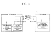
- FIG. 3 shows how the terminal B notifies the terminal A of a control signal (control information).
- FIG. 4 shows how the terminal A transmits an information signal to the terminal B.
- (a) represents a pilot signal sent from the terminal A
- (b) represents a control signal transmitted from the terminal B to the terminal A.
- FIG. 6 shows a configuration of a pilot signal detecting part at the terminal B.
- this embodiment will be described with reference to FIGS. 1 to 6 .
- This embodiment relates to a high efficient signal transmission method that is applicable to a MIMO system irrespective of the number of transmission/reception antennas in the system.
- the terminal A sends a pilot signal from each antenna 3 before sending an information signal (S101).
- the terminal B estimates a propagation vector of each pilot signal as transmission-related information (S102).
- S102 transmission-related information
- the terminal B determines, based on the estimated propagation vector, a transmission signal (transmission channel) to be used for sending an information signal (S103), and notifies the terminal A of the transmission signal to be used with a control signal (S104).
- the terminal A selects the antenna 3 to be used based on the transmission signal to be used, and sends an information signal to the terminal B (S105).
- a transmission antenna By performing control in accordance with such a procedure, a transmission antenna can be selected in accordance with a propagation environment, and efficient signal transmission can be performed.
- This embodiment is applicable to any cases irrespective of the transmission/reception antennas. Particularly, in the case where the number N of the transmission antennas is larger than the number M of the reception antennas, by reducing the number of the transmission antennas used for sending, the information signal can smoothly be separated and received at the terminal B.
- FIG. 1 shows a transmitter/receiver configuration in this control.
- the terminal A1 radio transmitter apparatus
- the terminal B2 radio receiver apparatus
- the terminal B2 includes a pilot signal detecting part 9, a transmission signal determining part 10, a control information transmitting part 11, and an information signal receiving part 12.
- the terminal A1 includes N antennas 3, and the terminal B2 includes M antennas 4.
- the signal sending part 6 of the terminal A1. sends a pilot signal from each antenna 3 before sending an information signal (S101).
- the pilot signal detecting part 9 of the terminal B detects (i.e., receives) the pilot signals from the terminal A through the antennas 4, and estimates a propagation vector of each pilot signal (S102). Although there are various specific methods of estimating a propagation vector, a specific example thereof will be described later.
- the transmission signal determining part 10 judges (i.e., determines) a transmission signal to be used for sending an information signal based on the estimated propagation vector. In this embodiment, a combination of transmission signals used for transmitting an information signal is determined (S103).
- the control information transmitting part 11 notifies the terminal A of the determined combination of transmission signals through the antennas 4 with a control signal (S104).
- FIG. 3 shows transmission of a control signal from the terminal B2 to the terminal A1 .
- the terminal A1 receives the control signal from the terminal B2 through the antennas 3 at the control information receiving part 7, and the transmission signal determining part 8 determines a transmission signal to be used, based on the control signal, i.e., selects the antenna 3 to be used.
- the signal sending part 6 of the terminal A1 sends an information signal from the selected antenna 3 (S105), and the terminal B receives an information signal at the information signal receiving part 12.
- (a) represents a pilot signal 20 of this control
- (b) represents an example of each format of the control signal 21.
- the terminal A sends pilot signals s n (p), which are different from one another, from each antenna 3. Furthermore, in the control signal from the terminal B to the terminal A, the terminal A is notified of "1" in the case where transmission is performed with respect to antennas numbered #1 to #N, and notified of "0" in the case where transmission is not performed.
- Various types of signal formats are considered, and this format is merely an example. Any signal format may be used, as long as it is a pilot signal that can be used for estimating a propagation vector or a control signal that can notify the terminal A of a transmission signal to be used.
- FIG. 6 shows a configuration of estimating a propagation vector at the pilot signal detecting part 9 of the terminal B.
- the estimation of a propagation vector can be performed by obtaining a correlation between the received pilot signal and the known pilot signal s n (p) previously stored in the pilot signal detecting part 9 for each antenna.
- FIG. 6 shows an example in which a propagation vector is estimated, any configuration other than this may be used, as long as propagation information that is transmission-related information regarding a reception signal to a pilot signal is detected. Furthermore, any parameter other than a propagation vector may be used, as long as the parameter serves as effective propagation information regarding a pilot signal.
- the transmission signal determining part 10 selects a transmission signal using the information.
- Various methods of selecting a transmission signal are considered.
- the method of selecting a transmission signal is not limited to examples of a selection method described in Embodiments 2 to 5, and any selection method may be used as long as the transmission of an information signal is controlled using propagation information that is transmission-related information, whereby the efficiency of transmission is enhanced.
- This embodiment relates to an efficient transmission control method and communication system for a MIMO system in which a plurality of signals are subjected to space division multiplexing (SDM) transmission.
- SDM space division multiplexing
- this embodiment shows one specific method regarding a method of selecting a transmission signal for the terminal B in Embodiment 1.
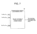
- FIG. 7 shows a transmission signal determining part 10 in this embodiment.
- FIG. 8 is a flowchart showing a control procedure in the transmission signal determining part 10.
- a method of selecting a transmission signal in this embodiment will be described with reference to FIGS. 7 and 8 .
- the transmission signal determining part 10 selects R signals having power as large as possible from among a plurality of transmission signals. Specifically, when received a propagation vector h n from the pilot signal detecting part 9, the transmission signal determining part 10 of the terminal B selects R signals in a decreasing order of norm ⁇ h n ⁇ (S201). Then, the transmission signal determining part 10 notifies the control information transmitting part 11 of numbers n of the selected signals (S202).
- each information signal can also be separated and received at the terminal B.
- a transmission signal (transmission channel) having a satisfactory propagation environment is selected to perform signal transmission. Furthermore, each information signal can smoothly be separated and received at the receiver.
- This embodiment relates to an efficient transmission control method and communication system for a MIMO system in which a plurality of signals are subjected to space division multiplexing (SDM) transmission.
- this embodiment relates to one method regarding a method of selecting a transmission signal at the terminal B in Embodiment 1, which is different from that of Embodiment 2.
- FIG. 9 shows a transmission signal determining part 10 in this embodiment
- FIG. 10 is a flowchart showing a control procedure in the transmission signal determining part 10.
- a method of selecting a transmission signal in this embodiment will be described with reference to FIGS. 9 and 10 .
- the transmission signal determining part 10 selects R signals from among a plurality of transmission signals such that the spatial correlation becomes as small as possible.
- the spatial correlation refers to a parameter defined by h n ⁇ 1 H ⁇ h n ⁇ 2 / ⁇ h n ⁇ 1 ⁇ ⁇ h n ⁇ 2 ⁇ or h n ⁇ 1 H ⁇ h n ⁇ 2 , and as this parameter is smaller, signals n1, n2 are in a state close to aspatially orthogonalrelationship. As the relationship between the signals is close to an orthogonal relationship, it is easy to separate two signals at the terminal B. According to this selection, signal transmission can be performed in an environment in which signals are likely to suppress one another. Accordingly, each information signal can easily be separated at the terminal B.
- the transmission signal determining part 10 selects a signal n at which a norm ⁇ h n ⁇ is maximum (S301). Then, the selected signal n is added to a group of a variable n1 (S302). In an initial state, the group of n1 does not have elements.
- a signal n at which the sum of spatial correlation of the signal belonging to the group n1 and the signal n: ⁇ n ⁇ 1 h n H ⁇ h n ⁇ 1 / ⁇ h n ⁇ ⁇ h n ⁇ 1 ⁇ is minimum is newly selected from the group other than the group of the variable n1 (S305), and the signal n is added to the group n1 as an element (S302). Furthermore, in a case where the number of elements of n1 is equal or larger than R at the end of Step S302 (S303), the control information transmitting part 11 is notified of the number selected as the group n1 (S304), and the processing is completed.
- a combination of signals having a small spatial correlation can be selected, and each information signal can smoothly be separated and received at the terminal B. Accordingly, high-efficient signal transmission can be performed. Furthermore, even in a case where the number N of transmission antennas is larger than the number M of reception antennas, by setting the number R of signals to be selected to be smaller than the number M of reception antennas, each information signal can be separated and received at the terminal B.
- This embodiment relates to an efficient transmission control method and communication system in aMIMO system in which a plurality of signals are subjected to space division multiplexing (SDM) transmission.
- this embodiment relates to one method of selecting a transmission signal at the terminal B in Embodiment 1, which is different from those of Embodiment 2 and Embodiment 3.
- FIG. 11 shows a configuration of the transmission signal determining part 10 in this embodiment.
- FIG. 12 is a flowchart showing a control procedure in the transmission signal determining part 10.
- FIG. 13 shows an example of an SINR prediction method used in this embodiment, and
- FIG. 14 shows a correspondence table of an SINR for determining an evaluation value and an evaluation value in the transmission signal determining part 10.
- FIG. 15 shows results obtained by calculating an evaluation value with respect to various combinations of signals. A method of selecting a transmission signal of this embodiment will be described with reference to FIGS. 11 to 15 .
- the transmission signal determining part 10 includes a signal candidate selecting part 31, an output signal to interference-plus-noise ratio (SINR) calculating part (hereinafter, referred to as an output SINR calculating part) 32, a transmission evaluating part 33, and a use signal determining part 34.
- SINR signal to interference-plus-noise ratio
- the signal candidate selecting part 31 selects a candidate combination of transmission signals (S401).
- the output SINR calculating part 32 predicts an output SINR at the terminal B obtained in the case of sending a combination of transmission signals (S402). A specific example of a prediction method will be described later.
- the transmission evaluating part 33 determines an evaluation value with respect to the candidate combination of transmission signals from the predicted output SINR (S403). This evaluation is performed with respect to all various candidate combinations of transmission signals (S404).
- the use signal determining part 34 selects a combination of transmission signals whose evaluation value is highest, and notifies the control information transmitting part 11 of the combination (S405).
- FIG. 13 shows a method of predicting an output SINR of each signal performed in Step S402 in the output SINR calculating part 32.
- a reception weight v n is first calculated using an estimated propagation vector h n .
- the reception weight v n is given by the following expression.
- v n ⁇ n ⁇ 0 h n ⁇ 0 h n ⁇ 0 H - 1 ⁇ h n ⁇ 0 (in the case of the ZF standard)
- v n ⁇ n ⁇ 0 ⁇ h n ⁇ 0 ⁇ h n ⁇ 0 H + P N ⁇ I - 1 ⁇ h n ⁇ 0 (in the case of the MMSE standard)
- an output SINR can be obtained by the following (Expression 2).
- ⁇ n h n H ⁇ v n p 2 / v n H ⁇ ⁇ n ⁇ 0 ⁇ h n ⁇ 0 ⁇ h n ⁇ 0 H + P N ⁇ I ⁇ v n - h n H ⁇ v n p 2
- P N noise power, which is a value previously estimated.
- the reception weight v n may be a weight operation other than the ZF standard and the MMSE standard.
- the SINR prediction expression of (Expression 2) is applicable to any weight v n .
- the transmission evaluating part 33 determines a transmission evaluation value based on the SINR.
- a method of setting an evaluation value to 0 or 1 in accordance with the SINR will be described.
- this embodiment is not limited to the transmission evaluating method based on the SINR, and a combination of signals can be selected based on various evaluation standards.
- the present invention is applicable to any MIMO system in which a candidate combination of signals is assumed, transmission evaluation is performed, and transmission control is performed using results thereof.
- the transmission evaluating part 33 has a table for determining an evaluation value with respect to an SINR as shown in FIG. 14 .
- an evaluation value is set to1, and otherwise, set to 0. This evaluation is executed respectively with respect to an output SINR of each signal.
- FIG. 15 shows results obtained by performing the above evaluation with respect to various combinations 51 of signals.
- various combinations of signals sent by three antennas are used.
- results obtained by performing the prediction of the output SINR 52, the calculation of the evaluation value 53 of each signal, and the calculation of the total 54 of the evaluation values (total evaluation value) are summarized.
- the total 54 of the evaluation values is calculated with respect to a combination of each signal, and a combination 55 of signals in which the total 54 of the evaluation values becomes maximum in the use signal determining part 34.
- the total of evaluation values becomes maximum, and this combination 55 is selected. In the case where a plurality of combinations reaching the maximum evaluation value are present, any one of them is selected.
- the terminal A is notified of the selected combination of signals through the control information transmitting part 11.
- a transmission efficiency can be evaluated from various transmission environments, and a combination of signals having the most excellent transmission efficiency among them can be selected.
- a communication system having a high transmission efficiency can be built.
- This embodiment can be used for enhancing the transmission efficiency with respect to any number of transmission/reception antennas.
- the transmission speed can be improvedwhile achieving the state where signal division can be performed at the terminal B, thereby producing a great application effect.
- This embodiment relates to an efficient transmission control method and communication system in a MIMO system in which a plurality of signals are subjected to Spatial Division Multiplexing (SDM) transmission.
- SDM Spatial Division Multiplexing
- This embodiment has the same configuration of a transmitter/receiver as that of Embodiment 1. However, the control signal notified from the terminal B to the terminal A is different, and in this embodiment, a transmission format number of each transmission signal is notified.
- FIG. 16 shows a flowchart of a control procedure in the transmission signal determining part 10 in this embodiment.
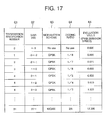
- FIG. 17 is a correspondence table of an output SINR for determining an evaluation value and an evaluation value in the transmission signal determining part 10.
- FIG. 18 shows results obtained by calculating an evaluation value with respect to various combinations of signals.
- FIG. 19 shows an example of a frame format of a control signals transmitted from the terminal B to the terminal A.
- this embodiment will be described with reference to FIGS. 16 to 19 .
- the transmission signal determining part 10 of this embodiment has the configuration in FIG. 11 in the same way as in Embodiment 4, and is composed of a signal candidate selecting part 31, an output SINR calculating part 32, a transmission evaluating part 33, and a use signal determining part 34.
- the signal candidate selecting part 31 selects a candidate combination of transmission signals (S501), and the output SINR calculating part 32 predicts an output SINR of a signal with respect to the combination (S502).
- the transmission evaluating part 33 determines an evaluation value based on the results of the output SINR (S503). This evaluation value is calculated with respect to all various candidate combinations of signals (S504), and finally, a combination of transmission signals having a highest evaluation value is selected by the use signal determining part 34.
- the use signal determining part 34 determines a transmission format suitable for sending a combination of signals, and notifies the control information transmitting part 11 of a transmission format number (S505).
- FIG. 17 is a table for determining an evaluation value with respect to an output SINR predicted value.
- This table shows a transmission format and a transmission speed that realize predetermined communication quality with respect to the output SINR predicted value.
- the predetermined communication quality refers to a required standard regarding a Bit Error Rate (BER), a Packet Error Rate (PER), or the like. More specifically, a format such as an encoding method (coding ratio, constraint length, etc.) and a modulation scheme is set to cause a transmission speed to be as high as possible within a range satisfying BER or PER of the required standard.
- BER Bit Error Rate
- PER Packet Error Rate
- FIG. 17 shows the modulation scheme 63, the coding ratio 64, and the like to be used under a certain SINR 62.
- the SINR increases, the endurance to a bit error becomes higher, so that a coding ratio can be set to be larger.
- multi-value modulation can also be used. As a result, the transmission speed 65 increases with the enhancement of the SINR.
- FIG. 18 shows results obtained by calculating a total 74 of evaluation values, using a transmission speed as an evaluation value 73 of each signal with respect to various combinations 71 of signals.
- the use signal determiningpart 34 selects a combination of signals at which the total 74 of evaluation values becomes maximum in FIG. 18 .
- a combination (1,1,0) of signals at which the total of evaluation values becomes 10.5 is selected.
- FIG. 19 is an example showing a configuration of the control signal 81, and a transmission format number is specified for each signal.
- “0” represents a transmission format number that is not used as a transmission signal.
- “8", “15”, and “6” represent transmission format numbers when used as transmission signals, and in this embodiment, as shown in FIG. 17 , transmission specification numbers "1" to "31" are selected in accordance with an SINR of each signal of the selected combination.
- the terminal B selects a transmission format number corresponding to a combination of transmission signals, and notifies the terminal A of the transmission format number.
- the terminal A that is notified of the transmission format number transmits an information signal in accordance with a transmission format and a transmission speed corresponding to the notified transmission format number.
- a transmission speed is used as an evaluation value
- a parameter other than the transmission speed may be used as an evaluation value.
- This embodiment relates to an efficient transmission control method and communication system in a MIMO system in which a plurality of signals are subjected to space division multiplexing (SDM) transmission.
- SDM space division multiplexing
- this embodiment shows SDM transmission performing multi-carrier transmission.
- FIG. 20 is a basic structural view illustrating general multi-carrier transmission.
- FIG. 21 is a structural view of transmission/reception in the case of applying the MIMO system to multi-carrier transmission.
- this embodiment will be described with reference to FIGS. 20 and 21 .
- FIG. 20 is a basic structural view of a multi-carrier communication system.
- a multi-carrier signal sending part 91 a plurality of signals are multiplexed (93 to 96) with a plurality of different frequencies, whereby signal transmission is performed.
- signals multiplexed (93 to 96) with a plurality of different frequencies are separated to obtain a reception signal of each carrier.
- the signals multiplexed in the multi-carrier signal sending part 91 are transmitted under the condition of being multiplexed (93 to 96) with a plurality of frequencies. In this case, signals transmitted by each carrier can be dealt with independently.
- individual signal processing can be performed for each carrier in the same way as in single-carrier transmission.
- the similar access control method can also be applied to the multi-carrier transmission system.
- FIG. 21 shows a configuration of signal processing in which the MIMO system of the present invention is applied to the multi-carrier transmission system.
- the MIMO system of the present invention can be applied to even the multi-carrier transmission system. That is, the terminal A1 includes multi-carrier signal sending parts 101 to 103, and the terminal B2 includes multi-carrier signal receiving parts 104 to 106.
- This embodiment shows a transmission control method and a communication system, different from those of Embodiment 6, in particular, regarding the SDM transmission performing multi-carrier transmission.
- Embodiment 6 By performing transmission control independently for each sub-carrier (each carrier) as shown in Embodiment 6, the control similar to that in the case of a single carrier can be performed. However, when independent control is performed with respect to all the sub-carriers, there is a problem in that a control amount increases. Then, in this embodiment, a method of enabling efficient signal transmission in a MIMO system while reducing a control amount will be described.
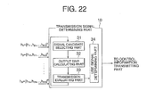
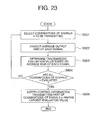
- FIG. 22 is a structural view of the transmission signal determining part 10, and FIG. 23 is a flowchart showing control performed in the transmission signal determining part 10.
- FIG. 24 shows an average SINR calculation method used in the transmission signal determining part 10.
- Embodiment 6 although the evaluation and the selection of a signal are performed for each sub-carrier, in this embodiment, one transmission evaluation and selection of a signal are performed with respect to all the sub-carriers. More specifically, an evaluation value with respect to all the sub-carriers is set, and the selection of a transmission signal of all the sub-carriers is performed in accordance with the evaluation value.
- the evaluation value various parameters such as average signal power, an average spatial correlation, and an average SINR can be used.
- the case of using an average SINR will be described as the use of one of the parameters.
- FIG. 22 shows a configuration of the transmission signal determining part 10 in the case of performing one transmission evaluation and signal selection with respect to all the sub-carriers.
- the signal candidate selecting part 31 selects a candidate combination of transmission signals (S601)
- the average output SINR calculating part 35 predicts an average output SINR (S602).
- the transmission evaluating part 33 determines an evaluation value with respect to the candidate combination of transmission signals from the prediction results of an average output SINR (S603). This evaluation is performed with respect to all various combinations of transmission signals (S604), and finally, the use signal determining part 34 selects a combination of transmission signals having a highest evaluation value and notifies the control information transmitting part 11 of the combination (S605).
- Embodiment 4 This procedure is configured in the same way as in Embodiment 4, except for using an average output SINR in place of output SINR. Furthermore, by using average signal power, an average spatial correlation, and an average SINR, even Embodiments 2, 3, and 5 can be extended to a control method of this embodiment during multi-carrier transmission.
- FIG. 24 shows a method of calculating average SINR.
- ⁇ n,l (n: transmission antenna number, l: sub-carrier number) that is an SINR of each sub-carrier is calculated in the same way as in Embodiment 4 with respect to a signal candidate. After this, by averaging an SINR among sub-carriers, ⁇ n that is an average SINR with respect to all the sub-carriers is calculated by the following Expression.
- the multi-carrier transmission encoding/decoding is generally performed over a plurality of sub-carriers in most cases.
- the multi-carrier reception characteristics greatly depend upon an average SINR, and the transmission characteristics can be substantially grasped based on the average SINR.
- efficient signal selection can be performed with a small control amount.
- a combination of signals to be used is selected using an average SINR, and the terminal A is notified of the combination with a control signal.
- the control signal is common to all the sub-carriers, and the control amount can be greatly reduced compared with Embodiment 6 in which a control method is required for each sub-carrier.
- This embodiment shows a method of sending a signal at the terminal A, which is different from Embodiments 1 to 7 in SDM transmission.
- the terminal A sends a pilot signal and an information signal from each antenna 3.
- the terminal A may not necessarily send a signal individually from each antenna 3.
- the case where the terminal A performs transmission of a pilot signal and an information signal using a transmission beam will be described.
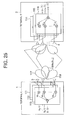
- FIG. 25 is a structural view of a transmitter/receiver in this embodiment.
- the terminal A1 includes transmission weight calculators 111, 112, and 113, and the terminal B2 includes reception weight multipliers 114, 115, and 116, whereby transmission beams 117, 118, and 119 are formed.
- FIG. 26 is a flowchart showing a control procedure in this embodiment. Hereinafter, this embodiment will be described with reference to FIGS. 25 and 26 .
- the terminal A multiplies the transmission signals by different weights w n to generate signals individually for the respective antennas 3, and sends a plurality of signals concurrently.
- the transmission signals of the terminal A have directivity, whereby transmission beams 117 to 119 are formed.
- the terminal A can also send signals from the respective transmission beams 117 to 119 instead of the respective antennas 3.
- the terminal A first sends pilot signals from the respective transmission beams 117 to 119 (S701).
- the terminal B estimates a propagation vector of each signal (S702).
- the terminal B determines a transmission beam to be used based on the estimated propagation vector (S703) and notifies the terminal A of a transmission beam to be used with a control signal.
- the terminal A selects a transmission beam to be used and sends an information signal to the terminal B (S705).
- the number of transmission beams is not necessarily the same as that of reception antennas.
- the number of transmission beams is determined based on the number of weight multipliers, and can be set to be either larger or smaller than the number of transmission antennas.
- the terminal A having two antennas 3 can also send four signals using four transmission beams.
- the application range of the methods of controlling transmission of Embodiments 1 and 8 can be further extended with respect to SDM transmission.
- Embodiment 8 and Embodiment 1 a method of controlling transmission has been stated based on the following premises:
- FIG. 27 shows a concept of this transmission control method
- FIG. 28 shows an example of a flowchart of this embodiment.
- the terminal A1 sends pilot signals 121 and 122 in either state (1) or (2) (S801).
- the terminal B2 can estimate propagation vectors with respect to the pilot signals even without recognizing either one of (1) and (2) (S802).
- the terminal B can estimate any of signal power, a spatial correlation, and an output SINR by learning only a series of pilot signals.
- the terminal B can also select appropriate signals corresponding to the pilot signals based on the results (S803).
- the terminal B can also notify the terminal A of a number of a transmission signal to be used (S804), thereby notifying the terminal A of the signal to be used.
- the terminal A having received a control signal sends an information signal to the terminal B from an antenna or a transmission beam (S805).
- the terminal B learns only a series of pilot signals, the terminal B can perform the entire transmission control smoothly even when the terminal A does not recognize any of the states (1) and (2). As a result, even when the terminal A uses an arbitrary transmission beam or the like irrespective of the terminal B, there arises no problem in transmission control.
- This embodiment relates to an efficient signal transmission method and communication system in aMIMO system in which a plurality of signals are subjected to space division multiplexing (SDM) transmission.
- SDM space division multiplexing
- this embodiment is characterized in that the terminal B determines transmission power of each signal, and notifies the terminal A of the transmission power in addition to a transmission format number.
- FIG. 29 shows results obtained by calculating an evaluation value with respect to various combinations of signals in the transmission signal determining part 10.
- FIG. 30 shows an example of a flowchart of this embodiment used in the transmission signal determining part 10.
- FIG. 31 is an example of frame format of a control signal 82 transmitted from the terminal B to the terminal A.
- this embodiment will be described with reference to FIGS. 29 to 31 .
- the transmission signal determining part 10 of this embodiment has the same configuration as that shown in FIG. 11 , and includes a signal candidate selecting part 31, an output SINR calculating part 32, a transmission evaluating part 33, and a use signal determining part 34.
- the transmission signal determining part 10 of this embodiment is different from that of the above-mentioned Embodiment 5 in that transmission power is also transmitted from the terminal B to the terminal A in addition to a transmission format number.
- the signal candidate selecting part 31 selects a combination 75 of levels of transmission power of each signal (S901), and the output SINR calculating part 32 predicts an output SINR 72 at the terminal B (S902).
- the transmission evaluating part 33 calculates an evaluation value (transmission speed) 73 with respect to each signal from the prediction results of each output SINR 72, and adds up the evaluation values with respect to the respective signals to determine a total 74 of transmission evaluation values (S903). This evaluation is performed with respect to various combinations of levels of transmission power of signals (S904), and finally, the use signal determining part 34 selects a combination of transmission power having a highest total of evaluation values and notifies the control information transmitting part 11 of the combination (S905).
- FIG. 29 shows results obtained by predicting the output SINR 72 with respect to various combinations 75 of levels of signal power, and calculating an evaluation value.
- the output SINR 72 is predicted.
- This SINR prediction can be per formed us ing the same operationmethod as that of (Expression 2).
- an evaluation value is determined using the predicted SINR.
- transmission power can be optimized. It should be noted that a combination of levels of power is created so that the total power of transmission signals is within a predetermined range.
- FIG. 31 shows an example showing a configuration of a control signal 82.
- the transmission power corresponding to each signal is described in the left column as a ratio with respect to the current pilot signal, and the numerical value in the right column represents a transmission format number.
- "0" to "3" are defined as the magnitude of the transmission power when used for a transmission signal, and "0" represents the case where the transmission format number is not used as a transmission signal.
- “0" shows that the transmission format number is not used as a transmission signal
- transmission specification numbers "1" to "31” are selected in the same way as in Embodiment 5.
- the terminal B selects a combination oftransmissionpower, and notifies the terminal A of the combination.
- the notified terminal A transmits an information signal in accordance with the notified transmission power and transmission format number.
- Examples 1 to 9 although a change in transmission power of a signal has not been considered, the power of each transmission signal can be optimized in this embodiment. As a result, signal transmission can be performed more efficiently in the MIMO system, considering also transmission power.
- Embodiment 5 although the case of applying a combination of power to Embodiment 5 has been described, the same procedure can be applied similarly to Embodiments 1 to 9. More specifically, the method of selecting power using an SINR described in this embodiment is merely one specific example of the present invention, and various configurations of a MIMO system, in which the terminal B determines power based on propagation information and performs transmission control, can be used.
- This embodiment shows the case where a MIMO system and a CDMA system are used in combination.
- Embodiments 1 to 10 When a DS-CDMA system and a multi-carrier CDMA system and a MIMO system are used in combination, after a code spreaded pilot signal is despreaded at the terminal B, the procedure similar to those of Embodiments 1 to 10 can be applied.
- the transmission control methods of Embodiments 1 to 10 can also be used in combination with a CDMA system such as the DS-CDMA system and the multi-carrier CDMA system.
- a receiver selects a transmission method of a signal from a transmitter based on a pilot signal from the transmitter, and notifies the transmitter of the transmission method, and the transmitter sends an information signal to the receiver in accordance with a signal transmissionmethod. Therefore, the present invention is applicable to a radio communication device in which signal separation can be performed smoothly, enhancing a transmission efficiency.
Abstract
Description
- The present invention relates to a radio transmission control method for a MIMO system in which a radio receiver apparatus and a radio transmitter apparatus respectively use a plurality of antennas to perform SDM transmission, and a radio receiver apparatus and a radio transmitter apparatus.
- Recently, radio communications has come into widespread use remarkably owing to its convenience. As a result, there is an urgent demand for takingmeasures to deal with the shortage of use frequencies. As one of the techniques of using the use frequency effectively, there is a MIMO (Multiple-Input Multiple-Output) system for performing high-speed signal transmission using a plurality of antennas in a transmitter/receiver, which is under active studies. In the MIMO system, it is known that a higher capacity can be achieved by using a plurality of antennas in a transmitter/receiver, compared with the case where the transmitter/receiver has one antenna.
- In the MIMO system, SDM (Space Division Multiplexing) transmission has been mostly studied, in which signals are sent individually from a plurality of transmission antennas, and each signal is extracted with signal processing on a receiving side. Hereinafter, a conventional technique will be described based on representative documents (for example, see Non-Patent
Documents 1 and 2) related to the SDM transmission. -
FIGS. 32 and33 show a configuration of a transmitter/receiver performing the SDM transmission. In the SDM transmission, time-series signals are sent individually from respective antennas of a transmitter, and as shown inFIG. 33 , a receiver receives the signals using beam formation corresponding to each transmission signal. A configuration of this signal processing will be described below. The description will be made assuming that the number of transmission antenna is N, the number of reception antennas is M, the channel gain from a transmission antenna n to a reception antenna m is hmn, and the propagation characteristics between the transmitter and the receiver is a matrix H=[hmn]. - As shown in
FIG. 32 , at a terminal A1 of the transmitter, time-series transmission signals Sn(p) (n = 1, ..., N) are transmitted fromN transmission antennas 3. The transmission signals pass through apropagation path 5 to be received byM reception antennas 4. At a terminal B2 of the receiver, receptionweight multiplying parts - Hereinafter, the above-mentioned series of processes will be shown using mathematical expressions. Assuming that a reception signal at the
reception antenna 4 is xm(p), a reception vector x (p) = [x1(p), ..., xM(p)]T (T is a transposition) is given by the following expression. -

Herein, s1(p), ..., sN(p) represents a transmission signal; hn = [hln, ..., hMn]T represents a propagation vector from thetransmission antenna 3 to theM reception antennas 4; z(p) = [z1(p), ..., zM(p)]T represents a noise and interference vector; and zm(p) represents a noise and interference component at theantenna 4. - Furthermore, the terminal B2 on the receiving side determines a weight vn = [vnl, ..., vnM]T suitable for receiving the signal sn(p) from the
transmission antenna 3. An output yn(p) after the signal combining is given by the following expression. -

- Although there are various methods for determining the reception weight vn, each reception weight vn is determined to get the transmission signal sn(p). For example, according to the weight determination based on a ZF (Zero Forcing) standard, the weight vn is determined so as to satisfy the following expressions.


- (Expression 1) shows the condition under which a desired signal sn(p) is received strongly, and the other signals sn0(p) (n0 is an integer other than n) are suppressed. Thus, only the desired signal can be received satisfactorily. Furthermore, by receiving a signal using different weights vn with respect to different n, a plurality of signals can be separated to be taken out, and hence, division multiplexing can be performed spatially. Herein, although a method for determining a weight based of the ZF standard has been described as an example, there is also a similar weight algorithm such as anMMSE synthesis method. The purpose of anyweight algorithm is basically to suppress signals other than a desired one in the same way as in (Expression 1).
- Thus, by suppressing signals other than a desired one among a plurality of signals at the terminal B2 on the receiving side, SDM (Space Division Multiplexing) can be realized. In the SDM transmission, a plurality of signals are transmitted simultaneously, so there is an advantage that high-speed signal transmission can be performed, compared with a conventional transmission system in which a transmitter/receiver uses a single antenna.
- However, actually, although (Expression 1) can be realized in the case where the number N of multiplexed signals is M or less (N ≤ M), it cannot be realized in the case of N > M. In order to understand the contents thereof, more detailed description will be made. In (Expression 1), the vectors vn and hn0 can be respectively expressed as one vector on an M-dimensional space. Furthermore, vn Thn0 being a vector inner product, and vn Thn0 being 0 correspond to a state where vn and hn0 are orthogonal to each other on the M-dimensional space. Although one vector vn orthogonal to (M-1) independent vectors hn0 can be set on the M-dimensional space, it is impossible to set a vector vn orthogonal to M or more independent vectors hn0. Thus, it is theoretically impossible to satisfy the relationship vn Thn0 = 0 with respect to M or more independent vectors hn0, and (Expression 1) does not hold for N > M.
- Accordingly, in the case where the number N of multiplexed signals is larger than the number M of reception antennas, any weight vn used on the receiving side cannot suppress other signals sufficiently. Therefore, the quality of a reception signal degrades rapidly. In order to avoid this situation, there is required a method of performing space division multiplexing transmission smoothly in an environment where the number of transmission antennas is larger than the number of reception antennas. However, such solution measures have not been introduced as yet.
- Non-Patent Document 1: A. V. Zelst, R.V. Nee, and G. A. Awater, "Space Division Multiplexing (SDM) for OFDM systems" IEEE Proc. of VTC 2000 Spring, pp. 1070 to 1074, 2000
Non-Patent Document 2: Kurosaki, Asai, Sugiyama, Umehira, "100 Mbit/s. SDM-COFDM over MIMO channel for broadband mobile communications" Technical Report, RCS 2001-135, Oct. 2001 - According to a beam formation method of a conventional procedure, in the case where the number of transmission antennas is smaller than the number of reception antennas, Space Division Multiplexing can be performed smoothly. However, in actual radio communication, there are a number of environments where the number of transmission antennas is larger than the number of reception antennas. In such a case, when different signals are sent simultaneously from respective transmission antennas using a conventional transmission method, the signals cannot be separated from one another on a receiving side, which greatly degrades the quality of the reception signals. Thus, there is a demand for a method capable of separating signals from one another and transmitting a signal of high quality in an environment where the number of transmission antennas is larger than the number of reception antennas.
- Furthermore, a method of sending signals using all the transmission antennas does not necessarily have a satisfactory transmission efficiency even in the case where the number of transmission antennas is smaller than the number of reception antennas. For example, in the case where two propagation vectors hn0 and hn1 are similar to each other, suppressing one signal hn1 may also suppress the desired signal hn0. In such a case, it may be better to stop one of the signals, rather than to sendboth signals, for performing signal transmission more satisfactory.
- Thus, controlling a procedure for sending signals raises the possibility of attaining more efficient signal transmission. There is a demand for a control method and a communication system between a transmitter and a receiver, enabling more efficient signal transmission over the MIMO system.
- According to the present invention, there is provided a radio transmission control method for a MIMO system including a radio transmitter apparatus having a plurality of antennas and a radio receiver apparatus having a plurality of antennas for transmitting a plurality of signals to each other through SDM, the method including the steps of: sending a pilot signal by the radio transmitter apparatus; receiving the pilot signal and estimating transmission-related information corresponding to the pilot signal by the radio receiver apparatus; selecting a transmission signal to be used in the radio transmitter apparatus based on the estimated transmission-related information; notifying the radio transmitter apparatus of a control signal describing the transmission signal to be used; and selecting an antenna to be used based on the control signal and sending the information signal from the selected antenna to the radio receiver apparatus, by the radio transmitter apparatus.
- Also, according to the present invention, there is provided a radio receiver apparatus for transmitting a signal with respect to a radio transmitter apparatus through SDM, including: a plurality of antennas for receiving a pilot signal sent from the radio transmitter apparatus; a pilot signal detecting part for estimating transmission-related information corresponding to the pilot signal received at the plurality of antennas; a transmission signal determining part for selecting a transmission signal to be used in the radio transmitter apparatus, based on the transmission-related information estimated by the pilot signal detecting part; and a control information transmitting part for notifying the radio transmitter apparatus of a control signal describing the transmission signals to be used selected by the transmission signal determining part.
- Further, according to the present invention, there is provided a radio transmitter apparatus for transmitting a signal with respect to a radio receiver apparatus through SDM, including: a signal sending part for sending pilot signals from a plurality of antennas to the radio receiver apparatus; a control information receiving part for receiving, from the radio receiver apparatus, a control signal describing a transmission signal to be used selected by the radio receiver apparatus based on the transmission-related information corresponding to the pilot signal ; and a transmission signal determining part for selecting an antenna to be used, based on the control signal received by the control information receiving part, in which the signal sending part sends an information signal from the antenna selected by the transmission signal determining part to the radio receiver apparatus.
- According to a radio transmission control method of the present invention, a radio receiver apparatus selects a transmission signal to be used based on a pilot signal from a radio transmitter apparatus and notifies the radio transmitter apparatus of the transmission signal, and the radio transmitter apparatus sends an information signal to the radio receiver apparatus based on the transmission signal to be used. Therefore, the radio receiver apparatus can receive an information signal that can be separated smoothly, and a transmission efficiency can be enhanced.
- Furthermore, a radio receiver apparatus of the present invention detects transmission-related information corresponding to a pilot signal sent from a radio transmitter apparatus, selects a transmission signal to be used based on the detected information, and notifies the radio transmitter apparatus of the selected transmission signal. Therefore, an information signal that can be separated smoothly in accordance with a propagation environment, the number of transmission/reception antennas, and the like, can be received, and a transmission efficiency can be enhanced.
- Furthermore, a radio transmitter apparatus of the present invention sends a pilot signal from a plurality of antennas, receives a transmission signal to be used, which is selected by a receiver based on transmission-related information corresponding to the pilot signal, and sends an information signal with the transmission signal to be used. Therefore, on the radio receiver apparatus side, an information signal that can be separated smoothly in accordance with a propagation environment, the number of transmission/reception antennas, and the like, can be received, and a transmission efficiency can be enhanced.
-
- [
FIG. 1 ] A basic structural view of a transmitter/receiver for a MIMO system inEmbodiment 1 of the present invention. - [
FIG. 2 ] A flowchart showing a transmission control method inEmbodiment 1. - [
FIG. 3 ] A view showing a situation in which a control signal is transmitted from a terminal B to a terminal A inEmbodiment 1. - [
FIG. 4 ] A view showing a situation in which an information signal is transmitted from the terminal A to the terminal B inEmbodiment 1. - [
FIG. 5 ] A format view of a pilot signal and a control signal used inEmbodiment 1. - [
FIG. 6 ] A structural view of a pilot signal detecting part of the terminal B inEmbodiment 1. - [
FIG. 7 ] A schematic view of a transmission signal determining part inEmbodiment 2. - [
FIG. 8 ] A flowchart showing a processing procedure in the transmission signal determining part inEmbodiment 2. - [
FIG. 9 ] A schematic view of a transmission signal determining part inEmbodiment 3. - [
FIG. 10 ] A flowchart showing a processing procedure in the transmission signal determining part inEmbodiment 3. - [
FIG. 11 ] A schematic view of a transmission signal determining part inEmbodiment 4. - [
FIG. 12 ] A flowchart showing a processing procedure in the transmission signal determining part inEmbodiment 4. - [
FIG. 13 ] A view showing an SINR prediction method inEmbodiment 4. - [
FIG. 14 ] A view of a table showing a relationship between an output SINR and an evaluation value inEmbodiment 4. - [
FIG. 15 ] A view of a table showing a correspondence between a combination of signals and an evaluation value inEmbodiment 4. - [
FIG. 16 ] A flowchart showing a control procedure in the transmission signal determining part inEmbodiment 4. - [
FIG. 17 ] A view of a table showing a relationship among an output SINR, a transmission format, and an evaluation value inEmbodiment 5. - [
FIG. 18 ] A view of a table showing a relationship between an output SINR and an evaluation value inEmbodiment 5. - [
FIG. 19 ] A view showing an example of a format of a control signal used inEmbodiment 5. - [
FIG. 20 ] A basic structural view of a multi-carrier communication system. - [
FIG. 21 ] A structural view of a transmitter/receiver of multi-carrier SDM transmission inEmbodiment 6. - [
FIG. 22 ] A configuration view of a configuration of a transmission signal determining part inEmbodiment 7. - [
FIG. 23 ] A flowchart showing a processing procedure in the transmission signal determining part inEmbodiment 7. - [
FIG. 24 ] A view of a calculation method of an average output SINR inEmbodiment 7. - [
FIG. 25 ] A basic structural view of a transmitter/receiver for a MIMO system inEmbodiment 8. - [
FIG. 26 ] A flowchart showing a transmission control method inEmbodiment 8. - [
FIG. 27 ] A conceptual view of a transmitter/receiver for a MIMO system inEmbodiment 9. - [
FIG. 28 ] A flowchart showing a transmission control method inEmbodiment 9. - [
FIG. 29 ] A view of a table showing a correspondence between a combination of signal powers and an evaluation value inEmbodiment 10. - [
FIG. 30 ] A flowchart showing a processing procedure in the transmission signal determining part inEmbodiment 10. - [
FIG. 31 ] A view showing one example of a format of a control signal used inEmbodiment 10. - [
FIG. 32 ] A structural view of a transmitter/receiver during SDMA transmission according to prior art. - [
FIG. 33 ] A conceptual viewof a transmitter/receiver configuration, and of reception beam formation during SDMA transmission according to prior art. - Hereinafter, each embodiment of the present invention will be described with reference to the drawings.
- This embodiment relates to an efficient signal transmission method and communication system in a MIMO system in which a plurality of signals are subjected to space division multiplexing (SDM) transmission. In the following description, a transmitting side of an information signal will be referred to as a terminal A, and a receiving side thereof will be referred to as a terminal B.
-
FIG. 1 is a most basic transmission/reception structural view showing this embodiment.FIG. 2 is a flowchart showing a control procedure of this embodiment.FIG. 3 shows how the terminal B notifies the terminal A of a control signal (control information).FIG. 4 shows how the terminal A transmits an information signal to the terminal B. InFIG. 5 , (a) represents a pilot signal sent from the terminal A, and (b) represents a control signal transmitted from the terminal B to the terminal A.FIG. 6 shows a configuration of a pilot signal detecting part at the terminal B. Hereinafter, this embodiment will be described with reference toFIGS. 1 to 6 . - This embodiment relates to a high efficient signal transmission method that is applicable to a MIMO system irrespective of the number of transmission/reception antennas in the system.
- Referring to
FIG. 2 , a basic control procedure of this embodiment will be described. First, in this embodiment, the terminal A sends a pilot signal from eachantenna 3 before sending an information signal (S101). When receiving the pilot signals, the terminal B estimates a propagation vector of each pilot signal as transmission-related information (S102). Although there are various specific methods of estimating a propagation vector, a specific example thereof will be described later. The terminal B determines, based on the estimated propagation vector, a transmission signal (transmission channel) to be used for sending an information signal (S103), and notifies the terminal A of the transmission signal to be used with a control signal (S104). When receiving the control signal, the terminal A selects theantenna 3 to be used based on the transmission signal to be used, and sends an information signal to the terminal B (S105). - By performing control in accordance with such a procedure, a transmission antenna can be selected in accordance with a propagation environment, and efficient signal transmission can be performed. This embodiment is applicable to any cases irrespective of the transmission/reception antennas. Particularly, in the case where the number N of the transmission antennas is larger than the number M of the reception antennas, by reducing the number of the transmission antennas used for sending, the information signal can smoothly be separated and received at the terminal B.
-
FIG. 1 shows a transmitter/receiver configuration in this control. In the figure, the terminal A1 (radio transmitter apparatus) includes asignal sending part 6, a controlinformation receiving part 7, and a transmissionsignal determining part 8. On the other hand, the terminal B2 (radio receiver apparatus) includes a pilotsignal detecting part 9, a transmissionsignal determining part 10, a controlinformation transmitting part 11, and an informationsignal receiving part 12. - Furthermore, the terminal A1 includes
N antennas 3, and the terminal B2 includesM antennas 4. The propagation characteristics of apropagation path 5 between a transmitter and a receiver are represented as a matrix H = [hmn]. - An operation of this embodiment will be described in detail with reference to
FIGS. 1 and2 . Thesignal sending part 6 of the terminal A1. sends a pilot signal from eachantenna 3 before sending an information signal (S101). The pilotsignal detecting part 9 of the terminal B detects (i.e., receives) the pilot signals from the terminal A through theantennas 4, and estimates a propagation vector of each pilot signal (S102). Although there are various specific methods of estimating a propagation vector, a specific example thereof will be described later. The transmissionsignal determining part 10 judges (i.e., determines) a transmission signal to be used for sending an information signal based on the estimated propagation vector. In this embodiment, a combination of transmission signals used for transmitting an information signal is determined (S103). The controlinformation transmitting part 11 notifies the terminal A of the determined combination of transmission signals through theantennas 4 with a control signal (S104).FIG. 3 shows transmission of a control signal from the terminal B2 to the terminal A1 . The terminal A1 receives the control signal from the terminal B2 through theantennas 3 at the controlinformation receiving part 7, and the transmissionsignal determining part 8 determines a transmission signal to be used, based on the control signal, i.e., selects theantenna 3 to be used. After this, as shown inFIG. 4 , thesignal sending part 6 of the terminal A1 sends an information signal from the selected antenna 3 (S105), and the terminal B receives an information signal at the informationsignal receiving part 12. - In
FIG. 5 , (a) represents apilot signal 20 of this control, and (b) represents an example of each format of thecontrol signal 21. The terminal A sends pilot signals sn(p), which are different from one another, from eachantenna 3. Furthermore, in the control signal from the terminal B to the terminal A, the terminal A is notified of "1" in the case where transmission is performed with respect to antennas numbered #1 to #N, and notified of "0" in the case where transmission is not performed. Various types of signal formats are considered, and this format is merely an example. Any signal format may be used, as long as it is a pilot signal that can be used for estimating a propagation vector or a control signal that can notify the terminal A of a transmission signal to be used. -
FIG. 6 shows a configuration of estimating a propagation vector at the pilotsignal detecting part 9 of the terminal B. The estimation of a propagation vector can be performed by obtaining a correlation between the received pilot signal and the known pilot signal sn(p) previously stored in the pilotsignal detecting part 9 for each antenna. - More specifically, a propagation vector hn = [h11, h21, ... hM1]T can be estimated by the following expression with respect to a reception vector x (p) = [x1(p), ..., xM(p)]T.
-

- Herein, * represents a complex conjugate. Generally, this operation is realized using an MF (Matched Filter). Although
FIG. 6 shows an example in which a propagation vector is estimated, any configuration other than this may be used, as long as propagation information that is transmission-related information regarding a reception signal to a pilot signal is detected. Furthermore, any parameter other than a propagation vector may be used, as long as the parameter serves as effective propagation information regarding a pilot signal. - When the pilot
signal detecting part 9 calculates propagation information (estimation of a propagation vector), the transmissionsignal determining part 10 selects a transmission signal using the information. Various methods of selecting a transmission signal are considered. Hereinafter, inEmbodiments 2 to 5, some examples will be shown regarding the method of selecting a transmission signal. The present invention is not limited to examples of a selection method described inEmbodiments 2 to 5, and any selection method may be used as long as the transmission of an information signal is controlled using propagation information that is transmission-related information, whereby the efficiency of transmission is enhanced. - This embodiment relates to an efficient transmission control method and communication system for a MIMO system in which a plurality of signals are subjected to space division multiplexing (SDM) transmission. In particular, this embodiment shows one specific method regarding a method of selecting a transmission signal for the terminal B in
Embodiment 1. -
FIG. 7 shows a transmissionsignal determining part 10 in this embodiment.FIG. 8 is a flowchart showing a control procedure in the transmissionsignal determining part 10. Hereinafter, a method of selecting a transmission signal in this embodiment will be described with reference toFIGS. 7 and8 . - As shown in
FIG. 7 , the transmissionsignal determining part 10 selects R signals having power as large as possible from among a plurality of transmission signals. Specifically, when received a propagation vector hn from the pilotsignal detecting part 9, the transmissionsignal determining part 10 of the terminal B selects R signals in a decreasing order of norm ∥hn∥ (S201). Then, the transmissionsignal determining part 10 notifies the controlinformation transmitting part 11 of numbers n of the selected signals (S202). - According to the above selection, a channel having a satisfactory propagation environment can be selected to be used. Furthermore, by setting the number R of signals to be selected to be smaller than the number M of reception antennas, each information signal can also be separated and received at the terminal B.
- Thus, according to this embodiment, a transmission signal (transmission channel) having a satisfactory propagation environment is selected to perform signal transmission. Furthermore, each information signal can smoothly be separated and received at the receiver.
- This embodiment relates to an efficient transmission control method and communication system for a MIMO system in which a plurality of signals are subjected to space division multiplexing (SDM) transmission. In particular, this embodiment relates to one method regarding a method of selecting a transmission signal at the terminal B in
Embodiment 1, which is different from that ofEmbodiment 2. -
FIG. 9 shows a transmissionsignal determining part 10 in this embodiment, andFIG. 10 is a flowchart showing a control procedure in the transmissionsignal determining part 10. Hereinafter, a method of selecting a transmission signal in this embodiment will be described with reference toFIGS. 9 and10 . - As shown in
FIG. 9 , the transmissionsignal determining part 10 selects R signals from among a plurality of transmission signals such that the spatial correlation becomes as small as possible. Herein, the spatial correlation refers to a parameter defined by
and
as this parameter is smaller, signals n1, n2 are in a state close to aspatially orthogonalrelationship. As the relationship between the signals is close to an orthogonal relationship, it is easy to separate two signals at the terminal B. According to this selection, signal transmission can be performed in an environment in which signals are likely to suppress one another. Accordingly, each information signal can easily be separated at the terminal B. - As a specific control procedure, when the propagation vector hn is estimated in the pilot
signal detecting part 9 of the terminal B, first, the transmissionsignal determining part 10 selects a signal n at which a norm ∥hn∥ is maximum (S301). Then, the selected signal n is added to a group of a variable n1 (S302). In an initial state, the group of n1 does not have elements. In a case where the number of elements of the variable n1 is smaller than R (S303), a signal n at which the sum of spatial correlation of the signal belonging to the group n1 and the signal n:
is minimum is newly selected from the group other than the group of the variable n1 (S305), and the signal n is added to the group n1 as an element (S302). Furthermore, in a case where the number of elements of n1 is equal or larger than R at the end of Step S302 (S303), the controlinformation transmitting part 11 is notified of the number selected as the group n1 (S304), and the processing is completed. - According to such a series of processing, a combination of signals having a small spatial correlation can be selected, and each information signal can smoothly be separated and received at the terminal B. Accordingly, high-efficient signal transmission can be performed. Furthermore, even in a case where the number N of transmission antennas is larger than the number M of reception antennas, by setting the number R of signals to be selected to be smaller than the number M of reception antennas, each information signal can be separated and received at the terminal B.
- This embodiment relates to an efficient transmission control method and communication system in aMIMO system in which a plurality of signals are subjected to space division multiplexing (SDM) transmission. In particular, this embodiment relates to one method of selecting a transmission signal at the terminal B in
Embodiment 1, which is different from those ofEmbodiment 2 andEmbodiment 3. -
FIG. 11 shows a configuration of the transmissionsignal determining part 10 in this embodiment.FIG. 12 is a flowchart showing a control procedure in the transmissionsignal determining part 10.FIG. 13 shows an example of an SINR prediction method used in this embodiment, andFIG. 14 shows a correspondence table of an SINR for determining an evaluation value and an evaluation value in the transmissionsignal determining part 10.FIG. 15 shows results obtained by calculating an evaluation value with respect to various combinations of signals. A method of selecting a transmission signal of this embodiment will be described with reference toFIGS. 11 to 15 . - As shown in
FIG. 11 , the transmissionsignal determining part 10 includes a signalcandidate selecting part 31, an output signal to interference-plus-noise ratio (SINR) calculating part (hereinafter, referred to as an output SINR calculating part) 32, atransmission evaluating part 33, and a usesignal determining part 34. - In the transmission
signal determining part 10, first, the signalcandidate selecting part 31 selects a candidate combination of transmission signals (S401). The outputSINR calculating part 32 predicts an output SINR at the terminal B obtained in the case of sending a combination of transmission signals (S402). A specific example of a prediction method will be described later. Thetransmission evaluating part 33 determines an evaluation value with respect to the candidate combination of transmission signals from the predicted output SINR (S403). This evaluation is performed with respect to all various candidate combinations of transmission signals (S404). Finally, the usesignal determining part 34 selects a combination of transmission signals whose evaluation value is highest, and notifies the controlinformation transmitting part 11 of the combination (S405). -
FIG. 13 shows a method of predicting an output SINR of each signal performed in Step S402 in the outputSINR calculating part 32. - In calculation of the predicted SINR, a reception weight vn is first calculated using an estimated propagation vector hn.
- For example, in the case of a ZF standard and an MMSE synthesis standard, the reception weight vn is given by the following expression.

(in the case of the ZF standard)
(in the case of the MMSE standard) - By calculating power of a desired signal and an interference noise component with respect to the operated reception weight, an output SINR can be obtained by the following (Expression 2).

where PN is noise power, which is a value previously estimated. - The reception weight vn may be a weight operation other than the ZF standard and the MMSE standard. The SINR prediction expression of (Expression 2) is applicable to any weight vn.
- When the output SINR is thus obtained, the
transmission evaluating part 33 determines a transmission evaluation value based on the SINR. Herein, as a specific example, a method of setting an evaluation value to 0 or 1 in accordance with the SINR will be described. However, this embodiment is not limited to the transmission evaluating method based on the SINR, and a combination of signals can be selected based on various evaluation standards. - The present invention is applicable to any MIMO system in which a candidate combination of signals is assumed, transmission evaluation is performed, and transmission control is performed using results thereof.
- The
transmission evaluating part 33 has a table for determining an evaluation value with respect to an SINR as shown inFIG. 14 . Herein, in the case where the SINR is 4 dB or more, an evaluation value is set to1, and otherwise, set to 0. This evaluation is executed respectively with respect to an output SINR of each signal. -
FIG. 15 shows results obtained by performing the above evaluation with respect tovarious combinations 51 of signals. In this embodiment, various combinations of signals sent by three antennas are used. Herein, results obtained by performing the prediction of theoutput SINR 52, the calculation of theevaluation value 53 of each signal, and the calculation of the total 54 of the evaluation values (total evaluation value) are summarized. Thus, the total 54 of the evaluation values is calculated with respect to a combination of each signal, and acombination 55 of signals in which the total 54 of the evaluation values becomes maximum in the usesignal determining part 34. - In the example shown in
FIG. 15 , in the case where theantennas # 1 and #2 are used, and theantenna # 3 is not used, the total of evaluation values becomes maximum, and thiscombination 55 is selected. In the case where a plurality of combinations reaching the maximum evaluation value are present, any one of them is selected. The terminal A is notified of the selected combination of signals through the controlinformation transmitting part 11. - According to such a control method, a transmission efficiency can be evaluated from various transmission environments, and a combination of signals having the most excellent transmission efficiency among them can be selected. As a result, compared with the conventional MIMO system in which transmission control is not performed, a communication system having a high transmission efficiency can be built.
- This embodiment can be used for enhancing the transmission efficiency with respect to any number of transmission/reception antennas. In particular, when the number N of transmission antennas is larger than the number M of reception antennas, the transmission speed can be improvedwhile achieving the state where signal division can be performed at the terminal B, thereby producing a great application effect.
- This embodiment relates to an efficient transmission control method and communication system in a MIMO system in which a plurality of signals are subjected to Spatial Division Multiplexing (SDM) transmission. This embodiment has the same configuration of a transmitter/receiver as that of
Embodiment 1. However, the control signal notified from the terminal B to the terminal A is different, and in this embodiment, a transmission format number of each transmission signal is notified. -
FIG. 16 shows a flowchart of a control procedure in the transmissionsignal determining part 10 in this embodiment.FIG. 17 is a correspondence table of an output SINR for determining an evaluation value and an evaluation value in the transmissionsignal determining part 10.FIG. 18 shows results obtained by calculating an evaluation value with respect to various combinations of signals.FIG. 19 shows an example of a frame format of a control signals transmitted from the terminal B to the terminal A. Hereinafter, this embodiment will be described with reference toFIGS. 16 to 19 . - The transmission
signal determining part 10 of this embodiment has the configuration inFIG. 11 in the same way as inEmbodiment 4, and is composed of a signalcandidate selecting part 31, an outputSINR calculating part 32, atransmission evaluating part 33, and a usesignal determining part 34. As a control procedure, first, the signalcandidate selecting part 31 selects a candidate combination of transmission signals (S501), and the outputSINR calculating part 32 predicts an output SINR of a signal with respect to the combination (S502). Thetransmission evaluating part 33 determines an evaluation value based on the results of the output SINR (S503). This evaluation value is calculated with respect to all various candidate combinations of signals (S504), and finally, a combination of transmission signals having a highest evaluation value is selected by the usesignal determining part 34. In this case, the usesignal determining part 34 determines a transmission format suitable for sending a combination of signals, and notifies the controlinformation transmitting part 11 of a transmission format number (S505). -
FIG. 17 is a table for determining an evaluation value with respect to an output SINR predicted value. This table shows a transmission format and a transmission speed that realize predetermined communication quality with respect to the output SINR predicted value. Herein, the predetermined communication quality refers to a required standard regarding a Bit Error Rate (BER), a Packet Error Rate (PER), or the like. More specifically, a format such as an encoding method (coding ratio, constraint length, etc.) and a modulation scheme is set to cause a transmission speed to be as high as possible within a range satisfying BER or PER of the required standard. -
FIG. 17 shows themodulation scheme 63, thecoding ratio 64, and the like to be used under acertain SINR 62. In general, as the SINR increases, the endurance to a bit error becomes higher, so that a coding ratio can be set to be larger. Furthermore, multi-value modulation can also be used. As a result, thetransmission speed 65 increases with the enhancement of the SINR. - By using this table, it is possible to determine a transmission format for achieving predetermined required quality under a certain SINR, and a transmission speed thereof. Furthermore, if the transmission speed is used as an evaluation value, an evaluation value can also be calculated with respect to various combinations of signals.
-
FIG. 18 shows results obtained by calculating a total 74 of evaluation values, using a transmission speed as anevaluation value 73 of each signal with respect tovarious combinations 71 of signals. Theuse signal determiningpart 34 selects a combination of signals at which the total 74 of evaluation values becomes maximum inFIG. 18 . In this embodiment, a combination (1,1,0) of signals at which the total of evaluation values becomes 10.5 is selected. - By selecting a combination at which the total of evaluation values becomes maximum, a transmission speed can be enhanced while a required quality standard is being satisfied in a MIMO system.
- When a combination of signals is thus selected, a transmission format number is determined with reference to
FIG. 17 , and the terminal A is notified of the transmission format number through the controlinformation transmitting part 11.FIG. 19 is an example showing a configuration of thecontrol signal 81, and a transmission format number is specified for each signal. In this figure, "0" represents a transmission format number that is not used as a transmission signal. Furthermore, "8", "15", and "6" represent transmission format numbers when used as transmission signals, and in this embodiment, as shown inFIG. 17 , transmission specification numbers "1" to "31" are selected in accordance with an SINR of each signal of the selected combination. - As described above, the terminal B selects a transmission format number corresponding to a combination of transmission signals, and notifies the terminal A of the transmission format number. The terminal A that is notified of the transmission format number transmits an information signal in accordance with a transmission format and a transmission speed corresponding to the notified transmission format number.
- According to this procedure, communication with a higher transmission speed can be realized while satisfying required communication quality, compared with the conventional MIMO system in which transmission control is not performed and the above-mentioned
Embodiments 1 to 4. Thus, by adding a degree of freedom to the transmission format, more detailed system design can be performed, which can enhance a transmission speed. - In the above description, although a transmission speed is used as an evaluation value, a parameter other than the transmission speed may be used as an evaluation value.
- This embodiment relates to an efficient transmission control method and communication system in a MIMO system in which a plurality of signals are subjected to space division multiplexing (SDM) transmission. In particular, this embodiment shows SDM transmission performing multi-carrier transmission.
-
FIG. 20 is a basic structural view illustrating general multi-carrier transmission.FIG. 21 is a structural view of transmission/reception in the case of applying the MIMO system to multi-carrier transmission. Hereinafter, this embodiment will be described with reference toFIGS. 20 and21 . - Recently, in radio communication, there is a great demand for a system capable of performing higher-speed transmission and higher-speed movement, which necessitates broadband radio transmission. Regarding the transmission of a broadband signal, in particular, attention is being paid to a multi-carrier system performing parallel transmission of signals simultaneously using a plurality of carriers. According to the multi-carrier transmission system, low-speed data are arranged in parallel on a frequency, and sent simultaneously using different carriers. An attempt is made to enhance the transmission speed by performing parallel transmission of signals.
-
FIG. 20 is a basic structural view of a multi-carrier communication system. As shown in the figure, in a multi-carriersignal sending part 91, a plurality of signals are multiplexed (93 to 96) with a plurality of different frequencies, whereby signal transmission is performed. Furthermore, in the multi-carriersignal receiving part 92 on a receiving side, signals multiplexed (93 to 96) with a plurality of different frequencies are separated to obtain a reception signal of each carrier. As shown in this figure, the signals multiplexed in the multi-carriersignal sending part 91 are transmitted under the condition of being multiplexed (93 to 96) with a plurality of frequencies. In this case, signals transmitted by each carrier can be dealt with independently. More specifically, individual signal processing can be performed for each carrier in the same way as in single-carrier transmission. Thus, inEmbodiments 1 to 5, although the case of the single-carrier transmission has been described, the similar access control method can also be applied to the multi-carrier transmission system. -
FIG. 21 shows a configuration of signal processing in which the MIMO system of the present invention is applied to the multi-carrier transmission system. As shown in this figure, by configuring the MIMO system shown inEmbodiments 1 to 5 for each carrier, the MIMO system of the present invention can be applied to even the multi-carrier transmission system. That is, the terminal A1 includes multi-carriersignal sending parts 101 to 103, and the terminal B2 includes multi-carriersignal receiving parts 104 to 106. - This embodiment shows a transmission control method and a communication system, different from those of
Embodiment 6, in particular, regarding the SDM transmission performing multi-carrier transmission. - By performing transmission control independently for each sub-carrier (each carrier) as shown in
Embodiment 6, the control similar to that in the case of a single carrier can be performed. However, when independent control is performed with respect to all the sub-carriers, there is a problem in that a control amount increases. Then, in this embodiment, a method of enabling efficient signal transmission in a MIMO system while reducing a control amount will be described. -
FIG. 22 is a structural view of the transmissionsignal determining part 10, andFIG. 23 is a flowchart showing control performed in the transmissionsignal determining part 10.FIG. 24 shows an average SINR calculation method used in the transmissionsignal determining part 10. Hereinafter, this embodiment will be described with reference toFIGS. 22 to 24 . - In
Embodiment 6, although the evaluation and the selection of a signal are performed for each sub-carrier, in this embodiment, one transmission evaluation and selection of a signal are performed with respect to all the sub-carriers. More specifically, an evaluation value with respect to all the sub-carriers is set, and the selection of a transmission signal of all the sub-carriers is performed in accordance with the evaluation value. As the evaluation value, various parameters such as average signal power, an average spatial correlation, and an average SINR can be used. Herein, the case of using an average SINR will be described as the use of one of the parameters. -
FIG. 22 shows a configuration of the transmissionsignal determining part 10 in the case of performing one transmission evaluation and signal selection with respect to all the sub-carriers. According to this procedure, first, the signalcandidate selecting part 31 selects a candidate combination of transmission signals (S601), and the average output SINR calculating part 35 predicts an average output SINR (S602). A method of predicating and calculating an average output SINR will be described later. Thetransmission evaluating part 33 determines an evaluation value with respect to the candidate combination of transmission signals from the prediction results of an average output SINR (S603). This evaluation is performed with respect to all various combinations of transmission signals (S604), and finally, the usesignal determining part 34 selects a combination of transmission signals having a highest evaluation value and notifies the controlinformation transmitting part 11 of the combination (S605). - This procedure is configured in the same way as in
Embodiment 4, except for using an average output SINR in place of output SINR. Furthermore, by using average signal power, an average spatial correlation, and an average SINR, even Embodiments 2, 3, and 5 can be extended to a control method of this embodiment during multi-carrier transmission. -
FIG. 24 shows a method of calculating average SINR. Herein, Γn,l (n: transmission antenna number, l: sub-carrier number) that is an SINR of each sub-carrier is calculated in the same way as inEmbodiment 4 with respect to a signal candidate. After this, by averaging an SINR among sub-carriers, Γn that is an average SINR with respect to all the sub-carriers is calculated by the following Expression. -

where El[•] represents performing average regarding 1. - In the multi-carrier transmission, encoding/decoding is generally performed over a plurality of sub-carriers in most cases. In this case, the multi-carrier reception characteristics greatly depend upon an average SINR, and the transmission characteristics can be substantially grasped based on the average SINR. Thus, in the multi-carrier transmission, by using an averaging parameter with respect to all the sub-carriers, efficient signal selection can be performed with a small control amount.
- In this embodiment, a combination of signals to be used is selected using an average SINR, and the terminal A is notified of the combination with a control signal. In this case, the control signal is common to all the sub-carriers, and the control amount can be greatly reduced compared with
Embodiment 6 in which a control method is required for each sub-carrier. - This embodiment shows a method of sending a signal at the terminal A, which is different from
Embodiments 1 to 7 in SDM transmission. - In the SDM transmission of
Embodiments 1 to 7, the terminal A sends a pilot signal and an information signal from eachantenna 3. However, the terminal A may not necessarily send a signal individually from eachantenna 3. In this embodiment, the case where the terminal A performs transmission of a pilot signal and an information signal using a transmission beam will be described. -
FIG. 25 is a structural view of a transmitter/receiver in this embodiment. The terminal A1 includestransmission weight calculators reception weight multipliers FIG. 26 is a flowchart showing a control procedure in this embodiment. Hereinafter, this embodiment will be described with reference toFIGS. 25 and26 . - In this embodiment, the terminal A multiplies a transmission signal sn(p) by a weight wn = [wn1, wn2, ..., wnN]T to obtain a signal of each
antenna 3. In the case where there are a plurality of transmission signals, the terminal A multiplies the transmission signals by different weights wn to generate signals individually for therespective antennas 3, and sends a plurality of signals concurrently. In this case, the transmission signals of the terminal A have directivity, whereby transmission beams 117 to 119 are formed. Thus, the terminal A can also send signals from therespective transmission beams 117 to 119 instead of therespective antennas 3. - A procedure of transmission control of a MIMO system using transmission beam forming will be described with reference to
FIG. 26 below. The terminal A first sends pilot signals from therespective transmission beams 117 to 119 (S701). When receiving a pilot signal, the terminal B estimates a propagation vector of each signal (S702). Furthermore, the terminal B determines a transmission beam to be used based on the estimated propagation vector (S703) and notifies the terminal A of a transmission beam to be used with a control signal. When receiving the control signal, the terminal A selects a transmission beam to be used and sends an information signal to the terminal B (S705). - Thus, even in the case where the terminal A sends a signal using a transmission beam, efficient SDM transmission can be performed owing to the transmission control between the terminal A and the terminal B, respectively. Similarly, all the procedures of
Embodiments 1 to 7 canbe extended to the case of using a transmission beam. - The number of transmission beams is not necessarily the same as that of reception antennas. The number of transmission beams is determined based on the number of weight multipliers, and can be set to be either larger or smaller than the number of transmission antennas. For example, the terminal A having two
antennas 3 can also send four signals using four transmission beams. - In this embodiment, the application range of the methods of controlling transmission of
Embodiments - In
Embodiment 8 andEmbodiment 1, a method of controlling transmission has been stated based on the following premises: - (1) the terminal A transmits a pilot signal from each transmission beam; and
- (2) the terminal A transmits a pilot signal from each
antenna 3, respectively. However, actually, the terminal B can control transmission even without recognizing whether the state is (1) or (2). -
FIG. 27 shows a concept of this transmission control method, andFIG. 28 shows an example of a flowchart of this embodiment. The terminal A1 sends pilot signals 121 and 122 in either state (1) or (2) (S801). At this time, the terminal B2 can estimate propagation vectors with respect to the pilot signals even without recognizing either one of (1) and (2) (S802). Furthermore, the terminal B can estimate any of signal power, a spatial correlation, and an output SINR by learning only a series of pilot signals. Furthermore, the terminal B can also select appropriate signals corresponding to the pilot signals based on the results (S803). Furthermore, the terminal B can also notify the terminal A of a number of a transmission signal to be used (S804), thereby notifying the terminal A of the signal to be used. The terminal A having received a control signal sends an information signal to the terminal B from an antenna or a transmission beam (S805). - Thus, if the terminal B learns only a series of pilot signals, the terminal B can perform the entire transmission control smoothly even when the terminal A does not recognize any of the states (1) and (2). As a result, even when the terminal A uses an arbitrary transmission beam or the like irrespective of the terminal B, there arises no problem in transmission control.
- From the above results, only a series of pilot signals is determined as a standard previously between terminals, and the use of a transmission beam can be subjected to the free determination of each terminal. As a result, it is not necessary to perform recognition and notification with respect to the presence/absence of a beam between terminals, and the terminal A can use transmission beam formation with a small control amount.
- This embodiment relates to an efficient signal transmission method and communication system in aMIMO system in which a plurality of signals are subjected to space division multiplexing (SDM) transmission.
- Unlike the control signal sent from the terminal B to the terminal A in
Embodiment 5, in particular, this embodiment is characterized in that the terminal B determines transmission power of each signal, and notifies the terminal A of the transmission power in addition to a transmission format number. -
FIG. 29 shows results obtained by calculating an evaluation value with respect to various combinations of signals in the transmissionsignal determining part 10.FIG. 30 shows an example of a flowchart of this embodiment used in the transmissionsignal determining part 10.FIG. 31 is an example of frame format of acontrol signal 82 transmitted from the terminal B to the terminal A. Hereinafter, this embodiment will be described with reference toFIGS. 29 to 31 . - The transmission
signal determining part 10 of this embodiment has the same configuration as that shown inFIG. 11 , and includes a signalcandidate selecting part 31, an outputSINR calculating part 32, atransmission evaluating part 33, and a usesignal determining part 34. However, the transmissionsignal determining part 10 of this embodiment is different from that of the above-mentionedEmbodiment 5 in that transmission power is also transmitted from the terminal B to the terminal A in addition to a transmission format number. - As a control procedure, first, the signal
candidate selecting part 31 selects acombination 75 of levels of transmission power of each signal (S901), and the outputSINR calculating part 32 predicts anoutput SINR 72 at the terminal B (S902). Thetransmission evaluating part 33 calculates an evaluation value (transmission speed) 73 with respect to each signal from the prediction results of eachoutput SINR 72, and adds up the evaluation values with respect to the respective signals to determine a total 74 of transmission evaluation values (S903). This evaluation is performed with respect to various combinations of levels of transmission power of signals (S904), and finally, the usesignal determining part 34 selects a combination of transmission power having a highest total of evaluation values and notifies the controlinformation transmitting part 11 of the combination (S905). -
FIG. 29 shows results obtained by predicting theoutput SINR 72 with respect tovarious combinations 75 of levels of signal power, and calculating an evaluation value. Herein, assuming that the power of an information signal is changed with respect to the power of a pilot signal, theoutput SINR 72 is predicted. This SINR prediction can be per formed us ing the same operationmethod as that of (Expression 2). Furthermore, an evaluation value is determined using the predicted SINR. Thus, by calculating an evaluation value with respect to various combinations of levels of power, and selecting a combination having a highest total evaluation value, transmission power can be optimized. It should be noted that a combination of levels of power is created so that the total power of transmission signals is within a predetermined range. - Thus, when a combination of levels of power of each signal is selected, the terminal A is notified of a transmission format number of the combination through the control
information transmitting part 11 together with the transmission power determined with reference toFIG. 17 in the same way as inEmbodiment 5.FIG. 31 shows an example showing a configuration of acontrol signal 82. InFIG. 31 , the transmission power corresponding to each signal is described in the left column as a ratio with respect to the current pilot signal, and the numerical value in the right column represents a transmission format number. In the item of power of this control signal, "0" to "3" are defined as the magnitude of the transmission power when used for a transmission signal, and "0" represents the case where the transmission format number is not used as a transmission signal. Furthermore, regarding the transmission format number, "0" shows that the transmission format number is not used as a transmission signal, and regarding the numbers used as transmission signals, transmission specification numbers "1" to "31" are selected in the same way as inEmbodiment 5. - As described above, the terminal B selects a combination oftransmissionpower, and notifies the terminal A of the combination. The notified terminal A transmits an information signal in accordance with the notified transmission power and transmission format number.
- In Examples 1 to 9, although a change in transmission power of a signal has not been considered, the power of each transmission signal can be optimized in this embodiment. As a result, signal transmission can be performed more efficiently in the MIMO system, considering also transmission power.
- In this embodiment, although the case of applying a combination of power to
Embodiment 5 has been described, the same procedure can be applied similarly toEmbodiments 1 to 9. More specifically, the method of selecting power using an SINR described in this embodiment is merely one specific example of the present invention, and various configurations of a MIMO system, in which the terminal B determines power based on propagation information and performs transmission control, can be used. - This embodiment shows the case where a MIMO system and a CDMA system are used in combination.
- When a DS-CDMA system and a multi-carrier CDMA system and a MIMO system are used in combination, after a code spreaded pilot signal is despreaded at the terminal B, the procedure similar to those of
Embodiments 1 to 10 can be applied. Thus, the transmission control methods ofEmbodiments 1 to 10 can also be used in combination with a CDMA system such as the DS-CDMA system and the multi-carrier CDMA system. - A receiver selects a transmission method of a signal from a transmitter based on a pilot signal from the transmitter, and notifies the transmitter of the transmission method, and the transmitter sends an information signal to the receiver in accordance with a signal transmissionmethod. Therefore, the present invention is applicable to a radio communication device in which signal separation can be performed smoothly, enhancing a transmission efficiency.
Claims (4)
- A radio communication method for a radio communication system in which output signals are generated from a plurality of information signals and then transmitted to a system of communication partners from a plurality of antennas, comprising:- a reception step of receiving control information transmitted by the system of communication partners;- a weight determining step of determining, based on the received control information, a first weight for one of the plurality of information signals modulated by a first modulation scheme and encoded by a first encoding method with respect to the plurality of antennas, and determining a second weight for another one of the plurality of information signals modulated by a second modulation scheme and encoded by a second encoding method with respect to the plurality of antennas;- an operation step of generating a first operation result by multiplying the one of the plurality of information signals by the first weight, and generating a second operation result by multiplying the other one of the plurality of information signals by the second weight; and- a transmission step of generating, based on the first operation result and the second operation result, a plurality of the output signals each corresponding to one of the plurality of antennas, and transmitting the plurality of the output signals to the system of communication partners;- wherein the control information includes information for the weight with respect to the plurality of antennas and transmission format information for the modulation schemes and the encoding methods, wherein the transmission format information corresponds to the information for the weight.
- The method according to claim 1,
wherein the control information further includes information to determine the first and second weights from candidate weights the number of which is greater than the number of antennas. - A radio communication system in which output signals are generated from a plurality of information signals and then transmitted to a system of communication partners from a plurality of antennas, comprising:- reception means for receiving control information transmitted by the system of communication partners;- weight determining means for determining, based on the received control information, a first weight for one of the plurality of information signals modulated by a first modulation scheme and encoded by a first encoding method with respect to the plurality of antennas, and determining a second weight for another one of plurality of information signals modulated by a second modulation scheme and encoded by a second encoding method with respect to the plurality of antennas;- operation means for generating a first operation result by multiplying the one of the plurality of information signals by the first weight, and generating a second operation result by multiplying the other one of the plurality of information signals by the second weight; and- transmission means for generating a plurality of the output signals each corresponding to one of the plurality of antennas by one of applying different modulation schemes between the first operation result and the second operation result and applying different encoding methods between the first operation result and the second operation result, and transmitting the plurality of the output signals to the system of communication partners;- wherein the control information includes information for the weight with respect to the plurality of antennas and transmission format information for the modulation schemes and the encoding methods, wherein the transmission format information corresponds to the information for the weight.
- The system according to claim 3,
wherein the control information further includes information to determine the first and second weights from candidate weights the number of which is greater than the number of antennas.
Applications Claiming Priority (2)
| Application Number | Priority Date | Filing Date | Title |
|---|---|---|---|
| JP2003286184A JP2005057497A (en) | 2003-08-04 | 2003-08-04 | Radio transmission control method, radio receiving device and radio transmitting device |
| EP04771058A EP1662686A4 (en) | 2003-08-04 | 2004-07-29 | Radio transmission control method, radio receiver apparatus, and radio transmitter apparatus |
Related Parent Applications (2)
| Application Number | Title | Priority Date | Filing Date |
|---|---|---|---|
| EP04771058A Division EP1662686A4 (en) | 2003-08-04 | 2004-07-29 | Radio transmission control method, radio receiver apparatus, and radio transmitter apparatus |
| EP04771058.7 Division | 2004-07-29 |
Publications (3)
| Publication Number | Publication Date |
|---|---|
| EP2194660A2 true EP2194660A2 (en) | 2010-06-09 |
| EP2194660A3 EP2194660A3 (en) | 2013-05-01 |
| EP2194660B1 EP2194660B1 (en) | 2017-03-22 |
Family
ID=34113940
Family Applications (2)
| Application Number | Title | Priority Date | Filing Date |
|---|---|---|---|
| EP04771058A Ceased EP1662686A4 (en) | 2003-08-04 | 2004-07-29 | Radio transmission control method, radio receiver apparatus, and radio transmitter apparatus |
| EP10157630.4A Active EP2194660B1 (en) | 2003-08-04 | 2004-07-29 | Radio transmission control method and radio transmission system |
Family Applications Before (1)
| Application Number | Title | Priority Date | Filing Date |
|---|---|---|---|
| EP04771058A Ceased EP1662686A4 (en) | 2003-08-04 | 2004-07-29 | Radio transmission control method, radio receiver apparatus, and radio transmitter apparatus |
Country Status (6)
| Country | Link |
|---|---|
| US (3) | US8125963B2 (en) |
| EP (2) | EP1662686A4 (en) |
| JP (1) | JP2005057497A (en) |
| KR (3) | KR100926289B1 (en) |
| CN (3) | CN101697496B (en) |
| WO (1) | WO2005013528A1 (en) |
Families Citing this family (23)
| Publication number | Priority date | Publication date | Assignee | Title |
|---|---|---|---|---|
| US8249518B2 (en) | 2003-12-29 | 2012-08-21 | Telefonaktiebolaget Lm Ericsson (Publ) | Network controlled feedback for MIMO systems |
| ATE548828T1 (en) * | 2005-03-08 | 2012-03-15 | Ericsson Telefon Ab L M | METHOD AND ARRANGEMENT FOR ADVANCED ROUTING METRICS IN MULTI-JUNK NETWORKS |
| US20060203794A1 (en) * | 2005-03-10 | 2006-09-14 | Qualcomm Incorporated | Systems and methods for beamforming in multi-input multi-output communication systems |
| US8483200B2 (en) * | 2005-04-07 | 2013-07-09 | Interdigital Technology Corporation | Method and apparatus for antenna mapping selection in MIMO-OFDM wireless networks |
| JP4701849B2 (en) * | 2005-06-14 | 2011-06-15 | 日本電気株式会社 | Reception quality display method and system |
| JP2008545328A (en) * | 2005-07-04 | 2008-12-11 | テレフオンアクチーボラゲット エル エム エリクソン(パブル) | Improved point-to-point communication system |
| NZ566171A (en) * | 2005-08-22 | 2010-08-27 | Qualcomm Inc | Method and apparatus for selection of virtual antennas |
| CN1941664A (en) * | 2005-09-30 | 2007-04-04 | 松下电器产业株式会社 | Transmission antenna selecting method and apparatus based on judge feedback in radio communication system |
| US7657244B2 (en) * | 2005-10-27 | 2010-02-02 | Samsung Electronics Co., Ltd. | Methods of antenna selection for downlink MIMO-OFDM transmission over spatial correlated channels |
| JP4542980B2 (en) * | 2005-10-31 | 2010-09-15 | 株式会社東芝 | Wireless device |
| ATE523978T1 (en) * | 2005-12-27 | 2011-09-15 | Mitsubishi Electric Corp | METHOD AND DEVICE FOR NOTIFYING TO A SECOND TELECOMMUNICATIONS DEVICE INFORMATION RELATING TO INTERFERENCE COMPONENTS RECEIVED IN A FIRST TELECOMMUNICATIONS DEVICE IN CERTAIN FREQUENCY SUB-BANDS |
| CN101090286A (en) * | 2006-06-12 | 2007-12-19 | 清华大学 | Radio system, base station device and terminal device |
| GB2459058B (en) * | 2007-02-02 | 2011-10-26 | Lg Electronics Inc | Antenna switching method and method for transmitting and receiving signals for the same |
| US8489544B2 (en) * | 2007-06-04 | 2013-07-16 | John P. Ford | System and method for prioritization and display of aggregated data |
| US8588835B2 (en) * | 2007-07-06 | 2013-11-19 | Ntt Docomo, Inc. | Base station apparatus and directivity control method in mobile communication system |
| GB2453147B (en) * | 2007-09-27 | 2009-11-18 | Toshiba Res Europ Ltd | A wireless transmission device |
| JP5251304B2 (en) | 2008-07-04 | 2013-07-31 | 日本電気株式会社 | COMMUNICATION SYSTEM, RADIO COMMUNICATION DEVICE, AND COMMUNICATION METHOD |
| US8526380B1 (en) * | 2011-03-17 | 2013-09-03 | Sprint Communications Company L.P. | Dynamic transmission mode selection based on wireless communication device data rate capabilities |
| JP5708345B2 (en) * | 2011-07-26 | 2015-04-30 | 富士通株式会社 | Wireless device and communication control method |
| KR101932197B1 (en) | 2012-07-03 | 2018-12-24 | 삼성전자주식회사 | Method and apparatus for determining the number of antenna in the mimo communication system |
| WO2014047606A2 (en) * | 2012-09-24 | 2014-03-27 | President And Fellows Of Harvard College | Techniques for data synchronization using compressive sensing |
| US20140269409A1 (en) * | 2013-03-14 | 2014-09-18 | Telefonaktiebolaget L M Ericsson (Publ) | Explicit signaling of number of receiver antennas |
| EP3258616B1 (en) * | 2015-03-20 | 2019-05-08 | Huawei Technologies Co., Ltd. | Receiving device and signal receiving processing method |
Family Cites Families (28)
| Publication number | Priority date | Publication date | Assignee | Title |
|---|---|---|---|---|
| JP3862111B2 (en) * | 1997-08-05 | 2006-12-27 | ソニー株式会社 | Reception device, radio communication system, and communication method |
| JP2962299B2 (en) | 1998-01-09 | 1999-10-12 | 日本電信電話株式会社 | Multi-carrier signal transmission device |
| US6317466B1 (en) * | 1998-04-15 | 2001-11-13 | Lucent Technologies Inc. | Wireless communications system having a space-time architecture employing multi-element antennas at both the transmitter and receiver |
| JP2000209145A (en) * | 1999-01-20 | 2000-07-28 | Nippon Telegr & Teleph Corp <Ntt> | Multi-carrier signal transmitter-receiver |
| EP1065800A1 (en) * | 1999-07-02 | 2001-01-03 | Lucent Technologies Inc. | Code division multiple access system having improved pilot channels |
| KR100316777B1 (en) * | 1999-08-24 | 2001-12-12 | 윤종용 | Closed loop transmit antenna diversity method, base station apparatus and mobile station apparatus therefor in next generation mobile communication system |
| JP2001223623A (en) | 2000-02-07 | 2001-08-17 | Matsushita Electric Ind Co Ltd | Digital radio communication system |
| FI112562B (en) * | 2000-02-29 | 2003-12-15 | Nokia Corp | Determination of measurement apertures in mutual frequency measurement |
| KR100615887B1 (en) * | 2000-04-07 | 2006-08-25 | 삼성전자주식회사 | Wireless communication system with feedback and method thereof |
| AU2000238190A1 (en) | 2000-04-07 | 2001-10-23 | Nokia Corporation | Multi-antenna transmission method and system |
| JP2001333002A (en) | 2000-05-24 | 2001-11-30 | Ntt Docomo Inc | Method for estimating transmitting antenna weight in mobile communication system and mobile communication terminal |
| PT2271041T (en) | 2000-07-12 | 2019-01-17 | Qualcomm Inc | Method and apparatus for generating pilot signals in a mimo system |
| KR100493152B1 (en) | 2000-07-21 | 2005-06-02 | 삼성전자주식회사 | Transmission antenna diversity method, base station apparatus and mobile station apparatus therefor in mobile communication system |
| JP3709129B2 (en) * | 2000-08-29 | 2005-10-19 | 大日本スクリーン製造株式会社 | Substrate processing apparatus and substrate processing method |
| WO2002047286A2 (en) * | 2000-12-06 | 2002-06-13 | Nokia Corporation | Method for controlling the weighting of a data signal in the at least two antenna elements of a radio connection unit, module and communications system |
| JP4531969B2 (en) | 2000-12-21 | 2010-08-25 | 三菱電機株式会社 | Adaptive antenna receiver |
| US6961388B2 (en) * | 2001-02-01 | 2005-11-01 | Qualcomm, Incorporated | Coding scheme for a wireless communication system |
| DE10114052C1 (en) | 2001-03-15 | 2002-07-25 | Hertz Inst Heinrich | Radio transmission method within closed space uses simultaneous transmission and reception antenna elements and space-time encoders and decoders |
| US6859503B2 (en) | 2001-04-07 | 2005-02-22 | Motorola, Inc. | Method and system in a transceiver for controlling a multiple-input, multiple-output communications channel |
| JP3801460B2 (en) | 2001-04-19 | 2006-07-26 | 松下電器産業株式会社 | Base station apparatus and wireless communication method |
| US6751187B2 (en) | 2001-05-17 | 2004-06-15 | Qualcomm Incorporated | Method and apparatus for processing data for transmission in a multi-channel communication system using selective channel transmission |
| JP3660278B2 (en) | 2001-07-13 | 2005-06-15 | 松下電器産業株式会社 | Base station apparatus, mobile station apparatus, radio communication system, and radio communication method |
| US7359466B2 (en) * | 2001-08-24 | 2008-04-15 | Lucent Technologies Inc. | Signal detection by a receiver in a multiple antenna time-dispersive system |
| US20030125040A1 (en) * | 2001-11-06 | 2003-07-03 | Walton Jay R. | Multiple-access multiple-input multiple-output (MIMO) communication system |
| JP3889614B2 (en) | 2001-12-11 | 2007-03-07 | 三洋電機株式会社 | Communication channel assignment apparatus and radio base station |
| US7020110B2 (en) | 2002-01-08 | 2006-03-28 | Qualcomm Incorporated | Resource allocation for MIMO-OFDM communication systems |
| GB0212165D0 (en) * | 2002-05-27 | 2002-07-03 | Nokia Corp | A wireless system |
| JP4602641B2 (en) | 2002-10-18 | 2010-12-22 | 株式会社エヌ・ティ・ティ・ドコモ | Signal transmission system, signal transmission method and transmitter |
-
2003
- 2003-08-04 JP JP2003286184A patent/JP2005057497A/en active Pending
-
2004
- 2004-07-29 KR KR1020067002306A patent/KR100926289B1/en active IP Right Grant
- 2004-07-29 KR KR1020097006717A patent/KR100951330B1/en active IP Right Grant
- 2004-07-29 EP EP04771058A patent/EP1662686A4/en not_active Ceased
- 2004-07-29 CN CN200910175853.8A patent/CN101697496B/en active Active
- 2004-07-29 CN CN200910175854.2A patent/CN101657011B/en active Active
- 2004-07-29 KR KR1020097006716A patent/KR100951332B1/en active IP Right Grant
- 2004-07-29 US US10/567,339 patent/US8125963B2/en active Active
- 2004-07-29 EP EP10157630.4A patent/EP2194660B1/en active Active
- 2004-07-29 CN CN2004800218400A patent/CN1830168B/en active Active
- 2004-07-29 WO PCT/JP2004/010845 patent/WO2005013528A1/en active Application Filing
-
2009
- 2009-04-06 US US12/385,350 patent/US20090196368A1/en not_active Abandoned
-
2012
- 2012-02-09 US US13/369,352 patent/US8385295B2/en active Active
Non-Patent Citations (2)
| Title |
|---|
| A. V. ZELST; R.V. NEE; G. A. AWATER: "IEEE Proc. of VTC", 2000, SPRING, article "Space Division Multiplexing (SDM) for OFDM systems", pages: 1070 - 1074 |
| KUROSAKI; ASAI; SUGIYAMA; UMEHIRA: "Technical Report", 2001, RCS, article "100 Mbit/s. SDM-COFDM over MIMO channel for broadband mobile communications", pages: 2001 - 135 |
Also Published As
| Publication number | Publication date |
|---|---|
| CN101697496A (en) | 2010-04-21 |
| US20090196368A1 (en) | 2009-08-06 |
| JP2005057497A (en) | 2005-03-03 |
| EP1662686A1 (en) | 2006-05-31 |
| US20080056217A1 (en) | 2008-03-06 |
| US8125963B2 (en) | 2012-02-28 |
| KR20090037982A (en) | 2009-04-16 |
| EP2194660B1 (en) | 2017-03-22 |
| KR20090037981A (en) | 2009-04-16 |
| KR20060054417A (en) | 2006-05-22 |
| KR100926289B1 (en) | 2009-11-12 |
| US20120134437A1 (en) | 2012-05-31 |
| CN101657011B (en) | 2014-11-12 |
| CN1830168A (en) | 2006-09-06 |
| CN101697496B (en) | 2014-03-19 |
| US8385295B2 (en) | 2013-02-26 |
| CN101657011A (en) | 2010-02-24 |
| WO2005013528A1 (en) | 2005-02-10 |
| KR100951330B1 (en) | 2010-04-08 |
| EP1662686A4 (en) | 2009-08-12 |
| CN1830168B (en) | 2012-02-01 |
| KR100951332B1 (en) | 2010-04-09 |
| EP2194660A3 (en) | 2013-05-01 |
Similar Documents
| Publication | Publication Date | Title |
|---|---|---|
| US8385295B2 (en) | Radio transmission control method, radio receiver apparatus, and radio transmitter apparatus | |
| EP1807990B1 (en) | Method and apparatus for closed loop data transmission | |
| US7991066B2 (en) | Transmitter, receiver and method for controlling multiple input multiple output system | |
| EP1742405B1 (en) | Method for channel estimation with spatial division multiplexing in an orthogonal frequency division multiplexing system with multiple antennas | |
| KR101087813B1 (en) | Wireless communication system and wireless communication method | |
| CN102439868B (en) | Method, communication system and related equipments for data transmission | |
| EP2329606B1 (en) | Interference rejection combining for multi-user mimo telecommunications system | |
| EP1914947A1 (en) | Pre-coding for MIMO system | |
| EP1538772A1 (en) | Apparatus and method for transmitting data using eigenvector selection in MIMO mobile communication systems | |
| US20020118781A1 (en) | Method and device for multiple input/multiple output transmit and receive weights for equal-rate data streams | |
| US8111771B2 (en) | Wireless communication apparatus and method using beamforming | |
| US9124313B2 (en) | Multi-cell cooperative communication system and terminal device | |
| EP0981209A2 (en) | Wireless transmission method for antenna arrays, having improved resistance to fading | |
| US20050220215A1 (en) | Radio transmitting apparatus provided with transmitters and transmitting antennas | |
| CN101582710A (en) | Method, system and device for selecting antenna mode | |
| KR100992503B1 (en) | Apparatus for trasmitting a signal using eigen-antenna technique in wireless communication system and method thereof | |
| JP4810578B2 (en) | Wireless communication method and wireless communication system | |
| JP2009135942A (en) | Radio communication method and radio communication system | |
| KR101289938B1 (en) | Apparatus and method for receiving a signal in a mobile communication system using multiple input multiple output scheme | |
| JP2009182633A (en) | Radio communication system, radio communication device, and communication control method |
Legal Events
| Date | Code | Title | Description |
|---|---|---|---|
| PUAI | Public reference made under article 153(3) epc to a published international application that has entered the european phase |
Free format text: ORIGINAL CODE: 0009012 |
|
| AC | Divisional application: reference to earlier application |
Ref document number: 1662686 Country of ref document: EP Kind code of ref document: P |
|
| AK | Designated contracting states |
Kind code of ref document: A2 Designated state(s): DE FR GB |
|
| RIN1 | Information on inventor provided before grant (corrected) |
Inventor name: OTSUKI, TOMOAKI Inventor name: HARA, YOSHITAKA Inventor name: TAIRA, AKINORI Inventor name: SUDO, KENJI |
|
| RIN1 | Information on inventor provided before grant (corrected) |
Inventor name: HARA, YOSHITAKA Inventor name: OTSUKI, TOMOAKI Inventor name: SUDO, KENJI Inventor name: TAIRA, AKINORI |
|
| PUAL | Search report despatched |
Free format text: ORIGINAL CODE: 0009013 |
|
| AK | Designated contracting states |
Kind code of ref document: A3 Designated state(s): DE FR GB |
|
| RIC1 | Information provided on ipc code assigned before grant |
Ipc: H04W 52/42 20090101ALN20130322BHEP Ipc: H04B 7/06 20060101AFI20130322BHEP Ipc: H04L 1/00 20060101ALI20130322BHEP |
|
| 17P | Request for examination filed |
Effective date: 20131030 |
|
| RBV | Designated contracting states (corrected) |
Designated state(s): DE FR GB |
|
| GRAP | Despatch of communication of intention to grant a patent |
Free format text: ORIGINAL CODE: EPIDOSNIGR1 |
|
| RIC1 | Information provided on ipc code assigned before grant |
Ipc: H04B 7/06 20060101AFI20160914BHEP Ipc: H04W 52/42 20090101ALN20160914BHEP Ipc: H04L 1/00 20060101ALI20160914BHEP |
|
| RAP1 | Party data changed (applicant data changed or rights of an application transferred) |
Owner name: MITSUBISHI DENKI K.K. |
|
| INTG | Intention to grant announced |
Effective date: 20161004 |
|
| RIN1 | Information on inventor provided before grant (corrected) |
Inventor name: TAIRA, AKINORI Inventor name: HARA, YOSHITAKA Inventor name: SUDO, KENJI Inventor name: OTSUKI, TOMOAKI |
|
| GRAS | Grant fee paid |
Free format text: ORIGINAL CODE: EPIDOSNIGR3 |
|
| GRAA | (expected) grant |
Free format text: ORIGINAL CODE: 0009210 |
|
| AC | Divisional application: reference to earlier application |
Ref document number: 1662686 Country of ref document: EP Kind code of ref document: P |
|
| AK | Designated contracting states |
Kind code of ref document: B1 Designated state(s): DE FR GB |
|
| REG | Reference to a national code |
Ref country code: GB Ref legal event code: FG4D |
|
| REG | Reference to a national code |
Ref country code: DE Ref legal event code: R096 Ref document number: 602004050984 Country of ref document: DE |
|
| REG | Reference to a national code |
Ref country code: FR Ref legal event code: PLFP Year of fee payment: 14 |
|
| REG | Reference to a national code |
Ref country code: DE Ref legal event code: R097 Ref document number: 602004050984 Country of ref document: DE |
|
| PLBE | No opposition filed within time limit |
Free format text: ORIGINAL CODE: 0009261 |
|
| STAA | Information on the status of an ep patent application or granted ep patent |
Free format text: STATUS: NO OPPOSITION FILED WITHIN TIME LIMIT |
|
| 26N | No opposition filed |
Effective date: 20180102 |
|
| GBPC | Gb: european patent ceased through non-payment of renewal fee |
Effective date: 20170729 |
|
| PG25 | Lapsed in a contracting state [announced via postgrant information from national office to epo] |
Ref country code: GB Free format text: LAPSE BECAUSE OF NON-PAYMENT OF DUE FEES Effective date: 20170729 |
|
| REG | Reference to a national code |
Ref country code: FR Ref legal event code: PLFP Year of fee payment: 15 |
|
| REG | Reference to a national code |
Ref country code: DE Ref legal event code: R084 Ref document number: 602004050984 Country of ref document: DE |
|
| P01 | Opt-out of the competence of the unified patent court (upc) registered |
Effective date: 20230512 |
|
| PGFP | Annual fee paid to national office [announced via postgrant information from national office to epo] |
Ref country code: FR Payment date: 20230608 Year of fee payment: 20 |
|
| PGFP | Annual fee paid to national office [announced via postgrant information from national office to epo] |
Ref country code: DE Payment date: 20230607 Year of fee payment: 20 |