EP2193815A1 - Flexible container with a preformed fluid channel and infusion pump device using such a container - Google Patents
Flexible container with a preformed fluid channel and infusion pump device using such a container Download PDFInfo
- Publication number
- EP2193815A1 EP2193815A1 EP08170627A EP08170627A EP2193815A1 EP 2193815 A1 EP2193815 A1 EP 2193815A1 EP 08170627 A EP08170627 A EP 08170627A EP 08170627 A EP08170627 A EP 08170627A EP 2193815 A1 EP2193815 A1 EP 2193815A1
- Authority
- EP
- European Patent Office
- Prior art keywords
- flexible container
- container
- container according
- access opening
- connection element
- Prior art date
- Legal status (The legal status is an assumption and is not a legal conclusion. Google has not performed a legal analysis and makes no representation as to the accuracy of the status listed.)
- Granted
Links
- 239000012530 fluid Substances 0.000 title claims abstract description 55
- 238000001802 infusion Methods 0.000 title claims abstract description 47
- 239000003814 drug Substances 0.000 claims abstract description 50
- 239000007788 liquid Substances 0.000 claims abstract description 43
- 238000007789 sealing Methods 0.000 claims abstract description 36
- 238000003860 storage Methods 0.000 claims abstract description 32
- 239000000463 material Substances 0.000 claims abstract description 13
- 230000002093 peripheral effect Effects 0.000 claims description 2
- NOESYZHRGYRDHS-UHFFFAOYSA-N insulin Chemical compound N1C(=O)C(NC(=O)C(CCC(N)=O)NC(=O)C(CCC(O)=O)NC(=O)C(C(C)C)NC(=O)C(NC(=O)CN)C(C)CC)CSSCC(C(NC(CO)C(=O)NC(CC(C)C)C(=O)NC(CC=2C=CC(O)=CC=2)C(=O)NC(CCC(N)=O)C(=O)NC(CC(C)C)C(=O)NC(CCC(O)=O)C(=O)NC(CC(N)=O)C(=O)NC(CC=2C=CC(O)=CC=2)C(=O)NC(CSSCC(NC(=O)C(C(C)C)NC(=O)C(CC(C)C)NC(=O)C(CC=2C=CC(O)=CC=2)NC(=O)C(CC(C)C)NC(=O)C(C)NC(=O)C(CCC(O)=O)NC(=O)C(C(C)C)NC(=O)C(CC(C)C)NC(=O)C(CC=2NC=NC=2)NC(=O)C(CO)NC(=O)CNC2=O)C(=O)NCC(=O)NC(CCC(O)=O)C(=O)NC(CCCNC(N)=N)C(=O)NCC(=O)NC(CC=3C=CC=CC=3)C(=O)NC(CC=3C=CC=CC=3)C(=O)NC(CC=3C=CC(O)=CC=3)C(=O)NC(C(C)O)C(=O)N3C(CCC3)C(=O)NC(CCCCN)C(=O)NC(C)C(O)=O)C(=O)NC(CC(N)=O)C(O)=O)=O)NC(=O)C(C(C)CC)NC(=O)C(CO)NC(=O)C(C(C)O)NC(=O)C1CSSCC2NC(=O)C(CC(C)C)NC(=O)C(NC(=O)C(CCC(N)=O)NC(=O)C(CC(N)=O)NC(=O)C(NC(=O)C(N)CC=1C=CC=CC=1)C(C)C)CC1=CN=CN1 NOESYZHRGYRDHS-UHFFFAOYSA-N 0.000 description 6
- -1 Polypropylene Polymers 0.000 description 4
- 238000004519 manufacturing process Methods 0.000 description 4
- 229920000642 polymer Polymers 0.000 description 4
- 238000003466 welding Methods 0.000 description 4
- 102000004877 Insulin Human genes 0.000 description 3
- 108090001061 Insulin Proteins 0.000 description 3
- 238000004026 adhesive bonding Methods 0.000 description 3
- 239000003708 ampul Substances 0.000 description 3
- 238000013459 approach Methods 0.000 description 3
- 238000010276 construction Methods 0.000 description 3
- 238000006073 displacement reaction Methods 0.000 description 3
- 239000010408 film Substances 0.000 description 3
- 229940125396 insulin Drugs 0.000 description 3
- 238000007920 subcutaneous administration Methods 0.000 description 3
- 229920000089 Cyclic olefin copolymer Polymers 0.000 description 2
- 239000004713 Cyclic olefin copolymer Substances 0.000 description 2
- 239000004952 Polyamide Substances 0.000 description 2
- 239000004698 Polyethylene Substances 0.000 description 2
- 239000004743 Polypropylene Substances 0.000 description 2
- 238000013461 design Methods 0.000 description 2
- 230000001627 detrimental effect Effects 0.000 description 2
- 229940079593 drug Drugs 0.000 description 2
- 238000004049 embossing Methods 0.000 description 2
- 238000001125 extrusion Methods 0.000 description 2
- 239000011888 foil Substances 0.000 description 2
- 238000012423 maintenance Methods 0.000 description 2
- 239000012528 membrane Substances 0.000 description 2
- 238000000034 method Methods 0.000 description 2
- 238000012986 modification Methods 0.000 description 2
- 230000004048 modification Effects 0.000 description 2
- 229920002493 poly(chlorotrifluoroethylene) Polymers 0.000 description 2
- 229920002647 polyamide Polymers 0.000 description 2
- 239000005023 polychlorotrifluoroethylene (PCTFE) polymer Substances 0.000 description 2
- 229920000573 polyethylene Polymers 0.000 description 2
- 229920000139 polyethylene terephthalate Polymers 0.000 description 2
- 239000005020 polyethylene terephthalate Substances 0.000 description 2
- 239000002861 polymer material Substances 0.000 description 2
- 229920001155 polypropylene Polymers 0.000 description 2
- 108090000623 proteins and genes Proteins 0.000 description 2
- 238000002560 therapeutic procedure Methods 0.000 description 2
- 229920002725 thermoplastic elastomer Polymers 0.000 description 2
- 239000004793 Polystyrene Substances 0.000 description 1
- VYPSYNLAJGMNEJ-UHFFFAOYSA-N Silicium dioxide Chemical compound O=[Si]=O VYPSYNLAJGMNEJ-UHFFFAOYSA-N 0.000 description 1
- XUIMIQQOPSSXEZ-UHFFFAOYSA-N Silicon Chemical compound [Si] XUIMIQQOPSSXEZ-UHFFFAOYSA-N 0.000 description 1
- 239000013543 active substance Substances 0.000 description 1
- 239000012790 adhesive layer Substances 0.000 description 1
- 230000000712 assembly Effects 0.000 description 1
- 238000000429 assembly Methods 0.000 description 1
- 230000004888 barrier function Effects 0.000 description 1
- 239000003795 chemical substances by application Substances 0.000 description 1
- 239000011248 coating agent Substances 0.000 description 1
- 238000000576 coating method Methods 0.000 description 1
- 150000001875 compounds Chemical class 0.000 description 1
- 238000011109 contamination Methods 0.000 description 1
- 229920001577 copolymer Polymers 0.000 description 1
- 238000007872 degassing Methods 0.000 description 1
- 230000001419 dependent effect Effects 0.000 description 1
- 206010012601 diabetes mellitus Diseases 0.000 description 1
- 230000000694 effects Effects 0.000 description 1
- 239000005038 ethylene vinyl acetate Substances 0.000 description 1
- 239000004715 ethylene vinyl alcohol Substances 0.000 description 1
- 230000009969 flowable effect Effects 0.000 description 1
- 239000000499 gel Substances 0.000 description 1
- 230000003054 hormonal effect Effects 0.000 description 1
- 229940088597 hormone Drugs 0.000 description 1
- 239000005556 hormone Substances 0.000 description 1
- 230000001939 inductive effect Effects 0.000 description 1
- 230000036512 infertility Effects 0.000 description 1
- 238000002347 injection Methods 0.000 description 1
- 239000007924 injection Substances 0.000 description 1
- 238000007918 intramuscular administration Methods 0.000 description 1
- 238000001990 intravenous administration Methods 0.000 description 1
- 238000003475 lamination Methods 0.000 description 1
- 239000010410 layer Substances 0.000 description 1
- 239000002346 layers by function Substances 0.000 description 1
- 229910052751 metal Inorganic materials 0.000 description 1
- 239000002184 metal Substances 0.000 description 1
- 239000011104 metalized film Substances 0.000 description 1
- 235000016709 nutrition Nutrition 0.000 description 1
- TWNQGVIAIRXVLR-UHFFFAOYSA-N oxo(oxoalumanyloxy)alumane Chemical compound O=[Al]O[Al]=O TWNQGVIAIRXVLR-UHFFFAOYSA-N 0.000 description 1
- 230000000149 penetrating effect Effects 0.000 description 1
- 239000004800 polyvinyl chloride Substances 0.000 description 1
- 239000005033 polyvinylidene chloride Substances 0.000 description 1
- 238000002360 preparation method Methods 0.000 description 1
- 230000002265 prevention Effects 0.000 description 1
- 102000004196 processed proteins & peptides Human genes 0.000 description 1
- 108090000765 processed proteins & peptides Proteins 0.000 description 1
- 102000004169 proteins and genes Human genes 0.000 description 1
- 238000005086 pumping Methods 0.000 description 1
- 238000000275 quality assurance Methods 0.000 description 1
- 229910052710 silicon Inorganic materials 0.000 description 1
- 239000010703 silicon Substances 0.000 description 1
- 229910052814 silicon oxide Inorganic materials 0.000 description 1
- 239000002356 single layer Substances 0.000 description 1
- 239000007787 solid Substances 0.000 description 1
- 239000000243 solution Substances 0.000 description 1
- 238000010254 subcutaneous injection Methods 0.000 description 1
- 239000007929 subcutaneous injection Substances 0.000 description 1
- 239000000126 substance Substances 0.000 description 1
- 239000000725 suspension Substances 0.000 description 1
- 230000001225 therapeutic effect Effects 0.000 description 1
- 238000012546 transfer Methods 0.000 description 1
Images


Classifications
-
- A—HUMAN NECESSITIES
- A61—MEDICAL OR VETERINARY SCIENCE; HYGIENE
- A61M—DEVICES FOR INTRODUCING MEDIA INTO, OR ONTO, THE BODY; DEVICES FOR TRANSDUCING BODY MEDIA OR FOR TAKING MEDIA FROM THE BODY; DEVICES FOR PRODUCING OR ENDING SLEEP OR STUPOR
- A61M5/00—Devices for bringing media into the body in a subcutaneous, intra-vascular or intramuscular way; Accessories therefor, e.g. filling or cleaning devices, arm-rests
- A61M5/14—Infusion devices, e.g. infusing by gravity; Blood infusion; Accessories therefor
- A61M5/142—Pressure infusion, e.g. using pumps
- A61M5/145—Pressure infusion, e.g. using pumps using pressurised reservoirs, e.g. pressurised by means of pistons
- A61M5/148—Pressure infusion, e.g. using pumps using pressurised reservoirs, e.g. pressurised by means of pistons flexible, e.g. independent bags
-
- A—HUMAN NECESSITIES
- A61—MEDICAL OR VETERINARY SCIENCE; HYGIENE
- A61J—CONTAINERS SPECIALLY ADAPTED FOR MEDICAL OR PHARMACEUTICAL PURPOSES; DEVICES OR METHODS SPECIALLY ADAPTED FOR BRINGING PHARMACEUTICAL PRODUCTS INTO PARTICULAR PHYSICAL OR ADMINISTERING FORMS; DEVICES FOR ADMINISTERING FOOD OR MEDICINES ORALLY; BABY COMFORTERS; DEVICES FOR RECEIVING SPITTLE
- A61J1/00—Containers specially adapted for medical or pharmaceutical purposes
- A61J1/14—Details; Accessories therefor
- A61J1/1475—Inlet or outlet ports
-
- A—HUMAN NECESSITIES
- A61—MEDICAL OR VETERINARY SCIENCE; HYGIENE
- A61M—DEVICES FOR INTRODUCING MEDIA INTO, OR ONTO, THE BODY; DEVICES FOR TRANSDUCING BODY MEDIA OR FOR TAKING MEDIA FROM THE BODY; DEVICES FOR PRODUCING OR ENDING SLEEP OR STUPOR
- A61M5/00—Devices for bringing media into the body in a subcutaneous, intra-vascular or intramuscular way; Accessories therefor, e.g. filling or cleaning devices, arm-rests
- A61M5/14—Infusion devices, e.g. infusing by gravity; Blood infusion; Accessories therefor
- A61M5/141—Infusion devices, e.g. infusing by gravity; Blood infusion; Accessories therefor with capillaries for restricting fluid flow
-
- A—HUMAN NECESSITIES
- A61—MEDICAL OR VETERINARY SCIENCE; HYGIENE
- A61M—DEVICES FOR INTRODUCING MEDIA INTO, OR ONTO, THE BODY; DEVICES FOR TRANSDUCING BODY MEDIA OR FOR TAKING MEDIA FROM THE BODY; DEVICES FOR PRODUCING OR ENDING SLEEP OR STUPOR
- A61M5/00—Devices for bringing media into the body in a subcutaneous, intra-vascular or intramuscular way; Accessories therefor, e.g. filling or cleaning devices, arm-rests
- A61M5/14—Infusion devices, e.g. infusing by gravity; Blood infusion; Accessories therefor
- A61M5/1414—Hanging-up devices
- A61M5/1417—Holders or handles for hanging up infusion containers
-
- A—HUMAN NECESSITIES
- A61—MEDICAL OR VETERINARY SCIENCE; HYGIENE
- A61M—DEVICES FOR INTRODUCING MEDIA INTO, OR ONTO, THE BODY; DEVICES FOR TRANSDUCING BODY MEDIA OR FOR TAKING MEDIA FROM THE BODY; DEVICES FOR PRODUCING OR ENDING SLEEP OR STUPOR
- A61M5/00—Devices for bringing media into the body in a subcutaneous, intra-vascular or intramuscular way; Accessories therefor, e.g. filling or cleaning devices, arm-rests
- A61M5/178—Syringes
- A61M5/19—Syringes having more than one chamber, e.g. including a manifold coupling two parallelly aligned syringes through separate channels to a common discharge assembly
-
- A—HUMAN NECESSITIES
- A61—MEDICAL OR VETERINARY SCIENCE; HYGIENE
- A61J—CONTAINERS SPECIALLY ADAPTED FOR MEDICAL OR PHARMACEUTICAL PURPOSES; DEVICES OR METHODS SPECIALLY ADAPTED FOR BRINGING PHARMACEUTICAL PRODUCTS INTO PARTICULAR PHYSICAL OR ADMINISTERING FORMS; DEVICES FOR ADMINISTERING FOOD OR MEDICINES ORALLY; BABY COMFORTERS; DEVICES FOR RECEIVING SPITTLE
- A61J1/00—Containers specially adapted for medical or pharmaceutical purposes
- A61J1/05—Containers specially adapted for medical or pharmaceutical purposes for collecting, storing or administering blood, plasma or medical fluids ; Infusion or perfusion containers
- A61J1/10—Bag-type containers
-
- A—HUMAN NECESSITIES
- A61—MEDICAL OR VETERINARY SCIENCE; HYGIENE
- A61M—DEVICES FOR INTRODUCING MEDIA INTO, OR ONTO, THE BODY; DEVICES FOR TRANSDUCING BODY MEDIA OR FOR TAKING MEDIA FROM THE BODY; DEVICES FOR PRODUCING OR ENDING SLEEP OR STUPOR
- A61M2209/00—Ancillary equipment
- A61M2209/04—Tools for specific apparatus
- A61M2209/045—Tools for specific apparatus for filling, e.g. for filling reservoirs
Definitions
- the invention relates to a flexible container for storing a liquid medicament to be administered to a patient by an infusion pump device, a device for the automated release of a liquid medicament, particularly an infusion pump device comprising, incorporating and/or capable of using such a flexible container, and a connection element for use with such a flexible container, according to the preambles of the independent claims.
- Devices for the automated release of liquid medicaments are normally used with patients who have a continuous and in the course of the day varying need of a medicine which can be administered by subcutaneous infusion.
- Specific applications are, for example, certain pain therapies and the treatment of diabetes, in which computer controlled infusion pump devices, such as insulin pumps, are used.
- Such devices can be carried by a patient on the body, and contain a certain amount of liquid medicament in a medicine reservoir in the form of a container.
- the medicine reservoir often comprises medicine sufficient for one or several days.
- the liquid medicament is supplied to the patient's body from the medicine reservoir through an infusion cannula or an injection needle.
- the patients using the medicament in question and administering it themselves by means of an infusion pump are increasingly emphasizing convenience and discretion.
- the dimensions of such infusion devices are limited, and particular the overall length, width and thickness should be as small as possible, in order not be evident through clothing and to be carried as comfortable as possible.
- said devices are single-use devices for sterility and contamination prevention reasons. They may be delivered pre-filled with a certain liquid medicament, or empty, ready to be filled by a user.
- This self-filling of containers has the advantage that also medicaments that are not readily available in pre-filled containers can be used for such infusion pump devices, thereby providing the patient with a larger choice of sources for his medicaments.
- said devices or parts of it can be reused, for example by replacing an empty medicament container, or by refilling said container by the user.
- the standard infusion pump devices that are carried on or near the body have a medicine reservoir with a cylindrical ampoule and a displacement piston, which is pushed into the ampoule by a piston rod or threaded spindle in order to convey the liquid medicament.
- These known designs have the disadvantage of being longer and/or thicker than desired, the resulting dimensions being detrimental to the provision of compact infusion pumps.
- the infusion pump can be divided into structural assemblies which are each arranged in their own, smaller, housings and can be joined to one another by wireless or wired connection.
- An example of such a modular infusion pump device is disclosed in US 2006/0184119 A1 .
- containers of particularly flat construction may be replaced by a container with a rectangular or another suitable cross-section, interacting with a displacement piston of corresponding shape.
- WO 2008/122135 A1 Different embodiments of such compact medicine reservoir devices are shown in WO 2008/122135 A1 .
- a further approach to reduce the overall volume of an infusion device is to replace the syringe-type dosing mechanism, in which a piston is displaced along a long container axis by an actuator, thereby conveying the appropriate amount of liquid medicine, by a downstream pump system.
- a miniaturized pump is arranged downstream of the reservoir, and causes a suction pressure that conveys the product from the reservoir to its destination.
- An example for such a pump is WO 2004/009162 A1 .
- a suitable container for such devices is disclosed in US 2007/0123820 A1 , comprising a flat container and a flat piston body arranged in the body in a sliding manner. Fully filled, such a container has a ratio between its maximum height and its overall width of less than 1.25.
- the cross-section area of the container in relation to the displacement axis is much larger than for conventional cylinder-piston arrangements, and already a comparably small pressure gradient as generated by a miniaturized pump is able to overcome the friction force of the piston sealing gliding on the inner container wall.
- a flexible container may for example have the form of two flexible wall sheets that are sealed together.
- Flexible containers have the advantage of a smaller volume surplus of the container in relation to its content, which reduces the manufacture costs and the achievable dimensions of an infusion pump device using such a flexible container.
- the volume of a flexible container for use in an infusion pump device may be up to 10 ml, but is preferably 5 ml or less, and more preferably lies in a range of 1.5 to 3.5 ml.
- the flexible container For use in an infusion pump device the flexible container must be connected to a conduit system of the device.
- the flexible container may be provided with a port.
- a port can be mounted on the container with a flange sealed to a container wall sheet.
- US 2007/0049865 A1 discloses such a container.
- the port is provided with a septum, to be punctured by a hollow needle of the conduit system of the infusion pump device.
- Another possibility used for flexible containers are ports in the form of flexible tubes or rigid connection pieces welded between the two sheets of the container at the periphery of the flexible container. The fastening of the port to the container, for example by glueing or welding, requires a precise production control to avoid high rejection rates, and furthermore limits the choice of suitable materials.
- the resulting loss of useable container volume due to the dead volume is particularly high for smaller containers as they are suitable for infusion pumps, with a total volume of only 5 ml or less.
- the dead volume considerably increases the effective costs per dose and thus of the overall therapy costs, since a certain percentage of the medicament will inevitably remain in the container and has to be disposed. This cost effect is particularly important for expensive medicaments.
- the dead volume leads also to an increase of the overall volume of the flexible container, and thus of the infusion pump device with such a flexible container.
- One object of the invention is to provide a flexible container for storing a liquid medicament to be administered to a patient, which does not comprise the disadvantages of the known containers.
- a flexible container according to the invention should be easily connected to a device for the automated release of a liquid medicament.
- a flexible container according to the invention should have a reduced dead volume, and should be easily connected to a device for the automated release of a liquid medicament. It should also have dimensions that are suitable for being carried on or near the body.
- a flexible container according to the invention should be producible with high quality at low costs, and should comprise a minimum number of components.
- a further object of the invention is to provide an advantageous connection element for connecting a flexible container with a device for the automated release of a liquid medicament.
- Yet another object of the invention is to provide a device for the automated release of a liquid medicament comprising, incorporating, and/or capable of using such a flexible container.
- a flexible container for storing a liquid medicament comprises a wall consisting of two sheets of flexible material that are sealed together.
- the container comprises a storage volume, which is intended to contain the liquid medicament, and an access opening in fluid connection with the storage volume.
- Said access opening can be fluidly connected to an infusion pump device, either directly or using a suitable connection element.
- sealing elements are arranged around the access opening.
- Said sealing elements and/or connection elements have to exert a certain pressure force on the access opening, in order to obtain a liquid tight connection, and as a result the two wall sheets are pressed together in a certain sealing zone around the access point. As a result the access point would be isolated from the storage volume and the fluid flow blocked.
- a continuous connection between the access point and the storage volume is ensured by a fluid channel that is arranged between the storage volume and the access opening. This fluid channel is formed by a cavity in one or both of the wall sheets, thus bridging the two areas on both sides of the sealing zone and ensuring a continuing fluid connection between the storage volume and the access point.
- a further advantage of the fluid channel is the possibility to avoid that the wall sheets, which are continuously collapsing when liquid is retrieved from the flexible container, constrict part of the storage volume from the access opening, and thereby block the fluid flow. Since the cross-section of the fluid channel is much smaller than the overall cross-section of the storage volume, and has a vaulted shape, the stability of the flexible sheet material is sufficient to prevent the collapse of the fluid channel under the pressure difference generated by a pump device, even when the storage volume is completely drained.
- Yet another advantage of a flexible container with such a fluid channel is the fact that no additional components have to be placed inside the container, since the fluid channel is formed in the wall sheets.
- the inner diameter of the fluid channel should as small as possible. At the same time it must be sufficiently large to allow the liquid medicament to flow through the channel.
- the particular minimum dimensions depend on the viscosity of the liquid, the power of the pump device, and the maximum speed with which the liquid should be drawn out of the container and into the pump device.
- the cavity forming the fluid channel may be located between an oblong corrugation or groove in one of the wall sheets and the opposite wall sheet. It is also possible that both of the sheets are provided with oblong corrugations or grooves oriented parallel to each other.
- the corrugation or groove can be produced by thermal forming or hot embossing the sheet like material of the wall, or any other suitable method for producing a cavity between two sheets. For example a portion of a sheet may be gathered to form a pleat, prior to the laminar sealing with the second sheet, thereby forming the cavity.
- the container is provided with elements for positioning and/or fixating the container in a connection element of an infusion pump device.
- elements for positioning and/or fixating the container may be arranged in an area of the wall which is outside of the sealed area, and which does not belong to the containment of the storage volume.
- the access opening can be located at the end of the fluid channel opposite to the storage volume. Alternatively it may be located at any position on the fluid channel, which has the advantage that liquid can flow from two or more directions to the access opening.
- the access opening may most simply be a circular hole arranged in the wall sheet of the fluid channel or the wall sheet opposite to the wall sheet of the fluid channel. Such an embodiment has the advantage that no additional port is necessary for the access opening, which would have a detrimental internal dead volume.
- the access opening may have a diameter of about 1.5 mm or less.
- a flexible container according to the invention may comprise a cap or a closure element for closing the access opening. It may also be closed with cap or closure element that has to be removed prior to first use of the container.
- the cap or closure can be realized as a separate entity, or preferably is comprised by a connection element. In the latter variant, the flexible container as such would be open, and all closing and/or sealing elements are comprised by the connection element.
- part of or all closing and/or sealing elements are part of the flexible container.
- said elements can be mounted to the outside of one or both wall sheets, for example by glueing or welding.
- the access opening is opened manually or automatically with external elements, for example a suitable blade element or needle element.
- external elements for example a suitable blade element or needle element.
- Such an element can be arranged for example in a connection element interacting with the container.
- a container according to the invention may be provided with one or more ports mounted to the container wall, in addition to the access port. These additional ports may be used for transferring liquid to and from the interior of the container, or may be used to deaerate the container if needed.
- a container according to the invention can comprise one or more ports as disclosed in European Patent Application No. 08167548 of the applicant, which is incorporated by reference as part of this disclosure in its entirety.
- a container according to the invention can also have the structural elements of a flexible container as disclosed in said application.
- An advantageous connection element according to the invention for use in an infusion pump device comprises two clamp parts, which are adapted to positively and/or non-positively locking a flexible container, and fluidly connecting the access opening of the container to a conduit system of the connection element.
- a conduit system is used with a flexible container according to the invention.
- one or both clamp parts comprise sealing elements adapted to fluidly connecting the conduit system with the access opening of the flexible container. Additionally or alternatively one or both clamp parts may also comprise resilient elements directed towards the opposite clamp part, in order to increase the friction-lock of the container element or to improve the sealing.
- the surface of the clamp parts of the connection element is adapted to the exterior shape of the flexible container to be locked.
- connection element comprises further functional elements, e.g. a bubble filter, a degassing membrane, a pressure sensor, a pressure transfer membrane, a pump chamber and/or a pumping mechanism, complete or in part.
- functional elements e.g. a bubble filter, a degassing membrane, a pressure sensor, a pressure transfer membrane, a pump chamber and/or a pumping mechanism, complete or in part.
- connection element in yet another advantageous embodiment of a connection element according to the invention at least part of the connection element is realized as an integral part of a flexible container, permanently mounted on said flexible container.
- connection element in another advantageous embodiment of a connection element according to the invention at least part of the connection element is an integral part of an infusion pump device.
- An advantageous device for the automated release of a liquid medicament comprises, incorporates or is capable of using a flexible container according to the invention.
- it may comprise, incorporate or being capable of using the above-mentioned connection element.
- the terms “medicament” and “liquid medicament” are meant to encompass any drug-containing flowable medicine, or therapeutic or diagnostic liquid, capable of being passed through a delivery element such as a hollow needle in a controlled manner, such as a liquid, solution, gel or fine suspension.
- Representative drugs include pharmaceuticals such as peptides, proteins, and hormones, biologically derived or active agents, hormonal and gene based agents, nutritional formulas and other substances in both solid (dispensed) or liquid form.
- medicament encompasses insulin preparations ready for administration.
- subcutaneous infusion and “subcutaneous injection” are meant to encompass any method in which a needle device is inserted at a selected site within the body of a patient for subcutaneous, intravenous, intramuscular or intradermal delivery of a liquid medicament to a subject.
- needle defines a piercing member (including an array of micro needles) adapted to be introduced into or through the skin of a subject.
- FIG. 1 (a) An embodiment of a flexible container according to the invention is shown in Figure 1 (a)
- Figure 2 shows the same container 1 clamped in an embodiment of a connection element 5 according to the invention in Figure 2(a) .
- the flexible container 1 is shown in the empty, fully drained state. It comprises a wall 10, consisting of two sheets 101, 102 of flexible, liquid-tight material, sealed along a circumferential sealing rim 13. At a longitudinal end of the container 1 the sealing rim 13 merges with a sealed area 14, where a larger area of the sheets 101, 102 has been sealed together.
- the sealing of the sheets 101, 102 forming the wall 10 may be achieved by heat sealing, ultrasonic welding, high-frequency inductive welding, glueing, or any other suitable method for producing flexible containers from sheet-like material that is known to the skilled person.
- the sheet-like material may be a single foil of a suitable polymer, or a compound foil.
- the base area of a flexible container according to the invention may have any suitable shape, particularly square, rectangular, circular, oval, hexagonal shape. The shape may also be specially adapted to a specific infusion pump device.
- the wall of the container may also be produced from a single sheet that is folded along an axis, and is sealed along the remaining edges.
- Another possibility known from the state of the art is the use of continuous film tubes for producing the containers.
- the sheet like material of the wall can be a monolayer film or a multilayer structure.
- the container wall may consist of one or more polymers of the following families: Polypropylene (PP), Polyethylene (PE), and copolymers; Ethylene Vinyl Acetate (EVA), Polyvinyl Chloride (PVC), Polyvinylidene Chloride (PVDC), Polystyrene (PS), Ethylene Vinyl Alcohol (EVOH), Polyethylene Terephthalate (PET), Polyamide (PA), Polychlorotrifluoroethylene (PCTFE), Cyclic Olefin Copolymer (COC), Thermoplastic Elastomer (TPE), or generally any other polymer material which is known to the skilled person to be suitable for that purpose.
- PP Polypropylene
- PE Polyethylene
- copolymers Ethylene Vinyl Acetate
- PVC Polyvinyl Chloride
- PVDC Polyvinylidene Chloride
- PS Polystyrene
- the wall may be manufactured for example by extrusion, blown film extrusion, coextrusion or lamination.
- extrusion blown film extrusion
- coextrusion lamination
- lamination When producing a multilayer structure it may be necessary to include one or more tie layers, or to apply one or more adhesive layers between the functional layers.
- Figure 1 (b) shows a further embodiment of a flexible container 1 according to the invention, with an essentially rectangular shape.
- the sealing area 541 in which the sealing elements 54 are in contact with the container 1 is marked in grey.
- An access opening 12 is located at the longitudinal end of the container 1, which is in fluid connection with the storage volume 11 of the container via a fluid channel 122.
- Said access opening is embodied as a hole in the wall 10 at the end of the fluid channel 122 opposite to the storage volume 11, and can be connected to an infusion pump device, either directly or with a connection element 5, as shown in Figure 2 . Since no port is necessary for the fluid connection of the container to the infusion pump device, the overall dead volume is considerably reduced.
- the fluid channel 122 is embodied by an oblong cavity in the sealed area 14, located between the flat upper sheet 101 and the lower sheet 102, in which an oblong corrugation has been produced.
- a hole 17 is arranged in the sealed area 14, which can act as an element for precisely positioning and/or fixating the container, particular its access opening 12, in a connection element 5. Since the cross-section of the fluid channel 122 is much smaller than the cross-section of the storage volume 11, the flexible sheet material, having certain elasticity, will prevent the fluid channel from collapsing when the storage volume of the container is completely drained. The volume of the fluid channel 122 is much smaller than the total volume of the container, and thus its contribution to the dead volume of the container is negligible.
- the connection element 5 comprises two clamp parts 51, 52, between which a longitudinal end of the flexible container 1 can be clamped.
- the clamp parts may consist of any suitable stable, rigid material, such as metal or polymer.
- One first clamp part 51 comprises a pad 55 consisting of an elastic polymer material, arranged counter-sunk on the surface of the clamp part 51.
- the elastic pad 55 adapts its form to the protruding corrugation 127 of the fluid channel 122, respectively the wall sheet 102.
- Said pad acts as a resilient element 55, since it is slightly compressed when the clamp 51, 52 is closed, and presses the access opening 12 and the adjacent wall sheet 101 against sealing elements 54 of the connection element.
- the pad may also have a preformed oblong groove, corresponding to the outer shape of the fluid channel.
- the second clamp part 52 comprises a block with a conduit system 53, and sealing elements 54 for fluidly connecting the access opening 12 with said conduit system 53.
- the conduit system opens out into a hollow pin 532, which is located closely above the hole of the access opening 12.
- An O-Ring seal 54 is mounted on the hollow pin 532, for a liquid-tight connection between the container and the connection element.
- the conduit system 53 may lead to a tube directed to a pump device, or may end in an adapter that can be connected with an infusion pump device.
- a septum 531 is provided, for example made from silicon polymer, arranged directly above the hollow pin 531 and the access opening 12. It should be noted that such a septum 531 is only an optional feature. Through septum 531 a user may access the conduit system 54 and /or the container 1 with a syringe by penetrating the septum with a hollow needle. He may for example fill or refill the container with a liquid medicament, originating from a larger container, or he may clean the conduit system or deaerate the system. Another advantage of the septum 531 is the possibility for a user to puncture the sheet 101 of the wall 10 of the container with a needle, thereby opening the access opening of a previously hermetically closed and sealed container 1.
- the two parts After inserting the appropriate end of the flexible container 1 between the two clamp parts 51, 52 of the connection element, the two parts are locked together.
- a skilled person will know a number of different methods for friction-locking or form-locking said two parts.
- the first clamp part 51 is equipped with four snap bolts 57 (one not visible), which are inserted into corresponding holes of the second clamp part. Two of these snap bolts also act as elements for positioning and/or fixating, interacting with the elements for positioning and/or fixating 17 of the flexible container. Concretely said, the snap bolts 57 are inserted into the holes 17 of the container, thereby fixing its position in a definite way in relation to the clamp parts.
- the pump device (not shown) of an infusion pump, arranged downstream of the conduit system 53 of the connection element 5, sucks liquid, the liquid medicament in the container flows from the storage volume 11 through the fluid channel 122 and the access opening 12, and then via the conduit system 53 to the pump device.
- the container fully or partially filled in the beginning, will continuously collapse, until finally the two sheets 101, 102 abut to each other. Due to its increased structural rigidity, compared to the flexible container, the fluid channel 122 will not collapse, and a constant liquid flow from the storage volume 11 to the down-stream pump can be achieved, independent from the filling level of the flexible container.
- connection element 5 Another embodiment of a connection element according to the invention is shown in Figure 3 .
- the conduit system 53 does directly end at the septum 531, through which the conduit system 53 can be connected with the infusion pump device by a hollow needle.
- the lateral dimensions of the connection element 5 are chosen smaller than in Figure 2 .
- the first clamp part 51 does not comprise a resilient element, but a recess facing toward the container. The recess has a shape that corresponds to the fluid channel, thereby reducing the pressure on the fluid channel structure.
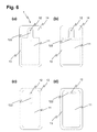
- connection element 5 is given in Figure 4(a) , where a conduit tube 53 is leading directly from a sealing element 54 positioned on top of the access opening 12 to the infusion pump device (not shown).
- a septum for accessing the container is not given.
- this embodiment is particularly suitable for a flexible container with an additional port for accessing the container.
- two positioning bolts 56 are visible, arranged on the first clamp part 51, which interact with holes 17 in the sealed area 14 of the container.
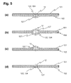
- the cavity 124 forming the fluid channel 122 was located between an oblong corrugation 127 in one 102 of the wall sheets and the other, opposite sheet 101 (see Figure 5(a) ).
- both of the sheets can have oblong corrugations oriented parallel to each other, as shown in Figure 5(b) .
- This variant requires a precise positioning of the two sheets in relation to each other.
- the access opening is located on the corrugation 127, and not on the flat sheet.
- one or both sheets may comprise a groove 127 or notch, as shown in Figure 5(d) .
- This requires a certain minimum thickness of the corresponding sheet material. Since the sealing area 14 remains flat, the clamp parts of a connection element locked to such a container can have a simpler design, because the surface of the clamp parts can be flat.
- a connection element according to the invention may be embodied as a separate unit, as shown in Figure 2 , or may be permanently attached to the flexible container, or may be directly attached to an infusion pump device.
- the first clamp part 51 be an integral part of a ground plate of an infusion pump device.
- the flexible container itself may be easily removed from the infusion pump device, or may be an integral part of the device.
- a user particularly a patient using the device, may replace an emptied container with a new, prefilled single-use container, or he may remove the container for refilling.
- Replaceable single-use containers are highly preferred for quality assurance reasons.
- the container is directly refilled in the device, for example by a septum in the connection element or by an additional port mounted on the container. If the container has to be replaced for maintenance reasons, this may be done by the user himself, or by a maintenance service.
- the inner side of the sheets, facing the interior storage volume 11 of the container are equipped with drain channels.
- This can be achieved for example by hot embossing a grid of lines on at least a part of the inner surface of the wall sheet 101, particularly on one or both sheets 101, 102 of the wall.
- the possible geometrical form of a flexible container according to the invention is not restricted to the essentially rectangular form as shown in Figures 1 and 2 , although a rectangular form is efficient and thus preferable.
- the form of the flexible container may be adapted to any specific need, particularly to the dimensions of a certain pump device. The same holds true for the form, position and dimensions of the inner storage volume and of the fluid channels, as well as the position of the access opening.
- Figure 6 shows as an example different variants of possible embodiments of flexible containers according to the invention, in a top view.
- two essentially rectangular wall sheets are sealed together along a sealing rim 13 and sealing area 14.
- the form and position of the storage volume 11 is defined by the sealing rim 13 and sealing area 14.
- the peripheral sealing rim 13 is extended toward the inner area of the wall sheets, forming a sealing area 14 that results in a specific shape of the storage volume 11.
- the fluid channel 122 may be positioned at any suitable place inside the container. It may be straight or bent, or may be even branched, as shown in Figure 6(b) .
- the access opening 12 does not necessarily have to be located at the end of the fluid channel 122. For example it may also be arranged in a central position of the fluid channel, collecting fluid from two ends of the fluid channel, as shown in Figure 6(d) .
- the embodiments in Figures 6(b) to (e) and (g) have the advantage that the zone in which fluid can be collected from the storage volume is extended.
- the embodiment in Figure 6(h) has the advantage that a connection element connected with the access opening 12 can be positioned at the periphery of the flexible container, instead of being positioned on the top, which allows a flatter construction of the overall infusion pump device.
Abstract
Description
- The invention relates to a flexible container for storing a liquid medicament to be administered to a patient by an infusion pump device, a device for the automated release of a liquid medicament, particularly an infusion pump device comprising, incorporating and/or capable of using such a flexible container, and a connection element for use with such a flexible container, according to the preambles of the independent claims.
- Devices for the automated release of liquid medicaments are normally used with patients who have a continuous and in the course of the day varying need of a medicine which can be administered by subcutaneous infusion. Specific applications are, for example, certain pain therapies and the treatment of diabetes, in which computer controlled infusion pump devices, such as insulin pumps, are used. Such devices can be carried by a patient on the body, and contain a certain amount of liquid medicament in a medicine reservoir in the form of a container. The medicine reservoir often comprises medicine sufficient for one or several days. The liquid medicament is supplied to the patient's body from the medicine reservoir through an infusion cannula or an injection needle.
- Particularly in self-administration of medicaments, for example insulin, the patients using the medicament in question and administering it themselves by means of an infusion pump are increasingly emphasizing convenience and discretion. As a consequence the dimensions of such infusion devices are limited, and particular the overall length, width and thickness should be as small as possible, in order not be evident through clothing and to be carried as comfortable as possible.
- Typically said devices are single-use devices for sterility and contamination prevention reasons. They may be delivered pre-filled with a certain liquid medicament, or empty, ready to be filled by a user. This self-filling of containers has the advantage that also medicaments that are not readily available in pre-filled containers can be used for such infusion pump devices, thereby providing the patient with a larger choice of sources for his medicaments. Alternatively said devices or parts of it can be reused, for example by replacing an empty medicament container, or by refilling said container by the user.
- The standard infusion pump devices that are carried on or near the body have a medicine reservoir with a cylindrical ampoule and a displacement piston, which is pushed into the ampoule by a piston rod or threaded spindle in order to convey the liquid medicament. These known designs have the disadvantage of being longer and/or thicker than desired, the resulting dimensions being detrimental to the provision of compact infusion pumps.
- Manufacturers try to meet the demand of small infusion pump devices by various means. For example the infusion pump can be divided into structural assemblies which are each arranged in their own, smaller, housings and can be joined to one another by wireless or wired connection. An example of such a modular infusion pump device is disclosed in
US 2006/0184119 A1 . - Another possibility is the use of containers of particularly flat construction. For example may the cylindrical ampoule be replaced by a container with a rectangular or another suitable cross-section, interacting with a displacement piston of corresponding shape. Different embodiments of such compact medicine reservoir devices are shown in
WO 2008/122135 A1 . - A further approach to reduce the overall volume of an infusion device is to replace the syringe-type dosing mechanism, in which a piston is displaced along a long container axis by an actuator, thereby conveying the appropriate amount of liquid medicine, by a downstream pump system. In such a device a miniaturized pump is arranged downstream of the reservoir, and causes a suction pressure that conveys the product from the reservoir to its destination. An example for such a pump is
WO 2004/009162 A1 . - For some of such infusion devices, the suction pressure achievable with such a pump system is not very high. A suitable container for such devices is disclosed in
US 2007/0123820 A1 , comprising a flat container and a flat piston body arranged in the body in a sliding manner. Fully filled, such a container has a ratio between its maximum height and its overall width of less than 1.25. The cross-section area of the container in relation to the displacement axis is much larger than for conventional cylinder-piston arrangements, and already a comparably small pressure gradient as generated by a miniaturized pump is able to overcome the friction force of the piston sealing gliding on the inner container wall. - In an especially advantageous approach the rigid container and movable piston are replaced by a flexible container. Such a flexible container may for example have the form of two flexible wall sheets that are sealed together. Flexible containers have the advantage of a smaller volume surplus of the container in relation to its content, which reduces the manufacture costs and the achievable dimensions of an infusion pump device using such a flexible container. The volume of a flexible container for use in an infusion pump device may be up to 10 ml, but is preferably 5 ml or less, and more preferably lies in a range of 1.5 to 3.5 ml.
- For use in an infusion pump device the flexible container must be connected to a conduit system of the device. For that purpose the flexible container may be provided with a port. Such a port can be mounted on the container with a flange sealed to a container wall sheet.
-
US 2007/0049865 A1 discloses such a container. The port is provided with a septum, to be punctured by a hollow needle of the conduit system of the infusion pump device. Another possibility used for flexible containers are ports in the form of flexible tubes or rigid connection pieces welded between the two sheets of the container at the periphery of the flexible container. The fastening of the port to the container, for example by glueing or welding, requires a precise production control to avoid high rejection rates, and furthermore limits the choice of suitable materials. - A common problem of flexible containers with ports as used, for example, in IV bags, is the dead volume resulting between the collapsed container and the port. Said dead volume cannot be used, meaning that it cannot be emptied. Thus a complete drainage of the contents of a flexible container is not possible. The resulting loss of useable container volume due to the dead volume is particularly high for smaller containers as they are suitable for infusion pumps, with a total volume of only 5 ml or less. For single-use container filled with the medicament, the dead volume considerably increases the effective costs per dose and thus of the overall therapy costs, since a certain percentage of the medicament will inevitably remain in the container and has to be disposed. This cost effect is particularly important for expensive medicaments. In addition to the increased costs, the dead volume leads also to an increase of the overall volume of the flexible container, and thus of the infusion pump device with such a flexible container.
- A further problem, particularly of flexible containers as they are known, is air remaining in the container. If for example a flexible container is provided empty, intended to be filled with the appropriate medicament by the user himself, the dead volume is initially filled with air. However, removing the air from flexible containers as they are known from the state of the art will require a certain skill of a user. If said air remains in the container, it may be administered instead of the liquid medicament, which leads to potentially dangerous dosing errors. Furthermore the administration of air into a patients body should be avoided for medical reasons.
- One object of the invention is to provide a flexible container for storing a liquid medicament to be administered to a patient, which does not comprise the disadvantages of the known containers. Particularly a flexible container according to the invention should be easily connected to a device for the automated release of a liquid medicament. Furthermore a flexible container according to the invention should have a reduced dead volume, and should be easily connected to a device for the automated release of a liquid medicament. It should also have dimensions that are suitable for being carried on or near the body.
- In addition a flexible container according to the invention should be producible with high quality at low costs, and should comprise a minimum number of components.
- A further object of the invention is to provide an advantageous connection element for connecting a flexible container with a device for the automated release of a liquid medicament.
- Yet another object of the invention is to provide a device for the automated release of a liquid medicament comprising, incorporating, and/or capable of using such a flexible container.
- These and other objects are achieved by a flexible container, a connection device, and an infusion pump device, according to the independent claims. Advantageous embodiments are given in the dependent claims.
- A flexible container for storing a liquid medicament according to the invention comprises a wall consisting of two sheets of flexible material that are sealed together. The container comprises a storage volume, which is intended to contain the liquid medicament, and an access opening in fluid connection with the storage volume. Said access opening can be fluidly connected to an infusion pump device, either directly or using a suitable connection element. In order to achieve a liquid tight connection between the access opening and the infusion pump device or the connection element, respectively, sealing elements are arranged around the access opening.
- Said sealing elements and/or connection elements have to exert a certain pressure force on the access opening, in order to obtain a liquid tight connection, and as a result the two wall sheets are pressed together in a certain sealing zone around the access point. As a result the access point would be isolated from the storage volume and the fluid flow blocked. However, a continuous connection between the access point and the storage volume is ensured by a fluid channel that is arranged between the storage volume and the access opening. This fluid channel is formed by a cavity in one or both of the wall sheets, thus bridging the two areas on both sides of the sealing zone and ensuring a continuing fluid connection between the storage volume and the access point.
- A further advantage of the fluid channel is the possibility to avoid that the wall sheets, which are continuously collapsing when liquid is retrieved from the flexible container, constrict part of the storage volume from the access opening, and thereby block the fluid flow. Since the cross-section of the fluid channel is much smaller than the overall cross-section of the storage volume, and has a vaulted shape, the stability of the flexible sheet material is sufficient to prevent the collapse of the fluid channel under the pressure difference generated by a pump device, even when the storage volume is completely drained.
- Yet another advantage of a flexible container with such a fluid channel is the fact that no additional components have to be placed inside the container, since the fluid channel is formed in the wall sheets.
- In order to minimize the dead volume and to maximize the rigidity and stability of the fluid channel, the inner diameter of the fluid channel should as small as possible. At the same time it must be sufficiently large to allow the liquid medicament to flow through the channel. The particular minimum dimensions depend on the viscosity of the liquid, the power of the pump device, and the maximum speed with which the liquid should be drawn out of the container and into the pump device. Thus with a fluid channel with suitable dimensions a constant and stable liquid flow from the storage volume to the access opening, and from there through the conduit system of a connection element to a downstream pump of an infusion pump device, can be provided independent of the sealing pressure force or current filling level of the flexible container. When the container is completely drained, no dead volume remains in the container except for the very small volume of the fluid channel.
- The cavity forming the fluid channel may be located between an oblong corrugation or groove in one of the wall sheets and the opposite wall sheet. It is also possible that both of the sheets are provided with oblong corrugations or grooves oriented parallel to each other. The corrugation or groove can be produced by thermal forming or hot embossing the sheet like material of the wall, or any other suitable method for producing a cavity between two sheets. For example a portion of a sheet may be gathered to form a pleat, prior to the laminar sealing with the second sheet, thereby forming the cavity.
- In a preferred embodiment the container is provided with elements for positioning and/or fixating the container in a connection element of an infusion pump device. For example two or more holes can be arranged in the sealed area of the container, which may interact with corresponding elements for positioning and/or fixating of a connection element, for example positioning bolts. Alternatively or additionally the elements for positioning and/or fixating the container may be arranged in an area of the wall which is outside of the sealed area, and which does not belong to the containment of the storage volume.
- The access opening can be located at the end of the fluid channel opposite to the storage volume. Alternatively it may be located at any position on the fluid channel, which has the advantage that liquid can flow from two or more directions to the access opening.
- The access opening may most simply be a circular hole arranged in the wall sheet of the fluid channel or the wall sheet opposite to the wall sheet of the fluid channel. Such an embodiment has the advantage that no additional port is necessary for the access opening, which would have a detrimental internal dead volume. The access opening may have a diameter of about 1.5 mm or less.
- A flexible container according to the invention may comprise a cap or a closure element for closing the access opening. It may also be closed with cap or closure element that has to be removed prior to first use of the container. The cap or closure can be realized as a separate entity, or preferably is comprised by a connection element. In the latter variant, the flexible container as such would be open, and all closing and/or sealing elements are comprised by the connection element.
- In another preferred embodiment part of or all closing and/or sealing elements are part of the flexible container. For example said elements can be mounted to the outside of one or both wall sheets, for example by glueing or welding.
- In another variant the access opening is opened manually or automatically with external elements, for example a suitable blade element or needle element. Such an element can be arranged for example in a connection element interacting with the container.
- A container according to the invention may be provided with one or more ports mounted to the container wall, in addition to the access port. These additional ports may be used for transferring liquid to and from the interior of the container, or may be used to deaerate the container if needed. Particularly a container according to the invention can comprise one or more ports as disclosed in European Patent Application No.
08167548 - An advantageous connection element according to the invention for use in an infusion pump device comprises two clamp parts, which are adapted to positively and/or non-positively locking a flexible container, and fluidly connecting the access opening of the container to a conduit system of the connection element. Preferably such a conduit system is used with a flexible container according to the invention.
- In a preferred embodiment of such a connection element, one or both clamp parts comprise sealing elements adapted to fluidly connecting the conduit system with the access opening of the flexible container. Additionally or alternatively one or both clamp parts may also comprise resilient elements directed towards the opposite clamp part, in order to increase the friction-lock of the container element or to improve the sealing. In an especially preferred embodiment of a connection element according to the invention, the surface of the clamp parts of the connection element is adapted to the exterior shape of the flexible container to be locked.
- In another advantageous embodiment of a connection element according to the invention the connection element comprises further functional elements, e.g. a bubble filter, a degassing membrane, a pressure sensor, a pressure transfer membrane, a pump chamber and/or a pumping mechanism, complete or in part.
- In yet another advantageous embodiment of a connection element according to the invention at least part of the connection element is realized as an integral part of a flexible container, permanently mounted on said flexible container.
- In another advantageous embodiment of a connection element according to the invention at least part of the connection element is an integral part of an infusion pump device.
- An advantageous device for the automated release of a liquid medicament, particularly an infusion pump device, comprises, incorporates or is capable of using a flexible container according to the invention. For that purpose it may comprise, incorporate or being capable of using the above-mentioned connection element.
- As used herein, the terms "medicament" and "liquid medicament" are meant to encompass any drug-containing flowable medicine, or therapeutic or diagnostic liquid, capable of being passed through a delivery element such as a hollow needle in a controlled manner, such as a liquid, solution, gel or fine suspension. Representative drugs include pharmaceuticals such as peptides, proteins, and hormones, biologically derived or active agents, hormonal and gene based agents, nutritional formulas and other substances in both solid (dispensed) or liquid form. In particular the term medicament encompasses insulin preparations ready for administration.
- The terms "subcutaneous infusion" and "subcutaneous injection" are meant to encompass any method in which a needle device is inserted at a selected site within the body of a patient for subcutaneous, intravenous, intramuscular or intradermal delivery of a liquid medicament to a subject. Further, the term needle defines a piercing member (including an array of micro needles) adapted to be introduced into or through the skin of a subject.
- In order to facilitate a fuller understanding of the present invention, reference is now made to the appended drawings. These references should not be construed as limiting the present invention, but are intended to be exemplary only.
-
Figure 1 schematically shows (a) a possible embodiments of a flexible container according to the invention in a perspective view, and (b) another possible embodiment in a top view. -
Figure 2 schematically shows the flexible container inFigure 1(a) , interacting with a possible embodiment of a connection element, (a) with the flexible container completely drained, (b) with the container filled, and (c) in a cross-section through the connection element, perpendicular to the longitudinal axis of the container. -
Figure 3 shows a detail of a cross-section of another embodiment of a connection element, interacting with a flexible container, (a) along the longitudinal axis of the container, and (b) perpendicular to the longitudinal axis. -
Figure 4 shows two other embodiments of a connection element, interacting with a flexible container. -
Figure 5 shows different variants of embodiments of the fluid channel in the sealed area of the wall of a container according to the invention. -
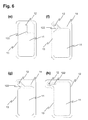
Figure 6 shows different variants of embodiments of the a flexible container according to the invention, in a top view. - An embodiment of a flexible container according to the invention is shown in
Figure 1 (a) , andFigure 2 shows thesame container 1 clamped in an embodiment of aconnection element 5 according to the invention inFigure 2(a) . Theflexible container 1 is shown in the empty, fully drained state. It comprises awall 10, consisting of twosheets circumferential sealing rim 13. At a longitudinal end of thecontainer 1 the sealingrim 13 merges with a sealedarea 14, where a larger area of thesheets sheets wall 10 may be achieved by heat sealing, ultrasonic welding, high-frequency inductive welding, glueing, or any other suitable method for producing flexible containers from sheet-like material that is known to the skilled person. The sheet-like material may be a single foil of a suitable polymer, or a compound foil. The base area of a flexible container according to the invention may have any suitable shape, particularly square, rectangular, circular, oval, hexagonal shape. The shape may also be specially adapted to a specific infusion pump device. Instead of sealing together two separate sheets, the wall of the container may also be produced from a single sheet that is folded along an axis, and is sealed along the remaining edges. Another possibility known from the state of the art is the use of continuous film tubes for producing the containers. - The sheet like material of the wall can be a monolayer film or a multilayer structure. The container wall may consist of one or more polymers of the following families: Polypropylene (PP), Polyethylene (PE), and copolymers; Ethylene Vinyl Acetate (EVA), Polyvinyl Chloride (PVC), Polyvinylidene Chloride (PVDC), Polystyrene (PS), Ethylene Vinyl Alcohol (EVOH), Polyethylene Terephthalate (PET), Polyamide (PA), Polychlorotrifluoroethylene (PCTFE), Cyclic Olefin Copolymer (COC), Thermoplastic Elastomer (TPE), or generally any other polymer material which is known to the skilled person to be suitable for that purpose.
- The wall may be manufactured for example by extrusion, blown film extrusion, coextrusion or lamination. When producing a multilayer structure it may be necessary to include one or more tie layers, or to apply one or more adhesive layers between the functional layers. To improve barrier properties one may also use metalized film, or a silicon oxide or aluminum oxide coating may be applied.
-
Figure 1 (b) shows a further embodiment of aflexible container 1 according to the invention, with an essentially rectangular shape. The sealingarea 541 in which thesealing elements 54 are in contact with thecontainer 1 is marked in grey. - An access opening 12 is located at the longitudinal end of the
container 1, which is in fluid connection with thestorage volume 11 of the container via afluid channel 122. Said access opening is embodied as a hole in thewall 10 at the end of thefluid channel 122 opposite to thestorage volume 11, and can be connected to an infusion pump device, either directly or with aconnection element 5, as shown inFigure 2 . Since no port is necessary for the fluid connection of the container to the infusion pump device, the overall dead volume is considerably reduced. - The
fluid channel 122 is embodied by an oblong cavity in the sealedarea 14, located between the flatupper sheet 101 and thelower sheet 102, in which an oblong corrugation has been produced. On both sides of the fluid channel ahole 17 is arranged in the sealedarea 14, which can act as an element for precisely positioning and/or fixating the container, particular itsaccess opening 12, in aconnection element 5. Since the cross-section of thefluid channel 122 is much smaller than the cross-section of thestorage volume 11, the flexible sheet material, having certain elasticity, will prevent the fluid channel from collapsing when the storage volume of the container is completely drained. The volume of thefluid channel 122 is much smaller than the total volume of the container, and thus its contribution to the dead volume of the container is negligible. - The
connection element 5 comprises twoclamp parts flexible container 1 can be clamped. The clamp parts may consist of any suitable stable, rigid material, such as metal or polymer. Onefirst clamp part 51 comprises apad 55 consisting of an elastic polymer material, arranged counter-sunk on the surface of theclamp part 51. Theelastic pad 55 adapts its form to the protrudingcorrugation 127 of thefluid channel 122, respectively thewall sheet 102. Said pad acts as aresilient element 55, since it is slightly compressed when theclamp adjacent wall sheet 101 against sealingelements 54 of the connection element. In another variant the pad may also have a preformed oblong groove, corresponding to the outer shape of the fluid channel. - The
second clamp part 52 comprises a block with aconduit system 53, and sealingelements 54 for fluidly connecting the access opening 12 with saidconduit system 53. The conduit system opens out into ahollow pin 532, which is located closely above the hole of theaccess opening 12. An O-Ring seal 54 is mounted on thehollow pin 532, for a liquid-tight connection between the container and the connection element. Theconduit system 53 may lead to a tube directed to a pump device, or may end in an adapter that can be connected with an infusion pump device. - In the shown embodiment of a connection element, furthermore a
septum 531 is provided, for example made from silicon polymer, arranged directly above thehollow pin 531 and theaccess opening 12. It should be noted that such aseptum 531 is only an optional feature. Through septum 531 a user may access theconduit system 54 and /or thecontainer 1 with a syringe by penetrating the septum with a hollow needle. He may for example fill or refill the container with a liquid medicament, originating from a larger container, or he may clean the conduit system or deaerate the system. Another advantage of theseptum 531 is the possibility for a user to puncture thesheet 101 of thewall 10 of the container with a needle, thereby opening the access opening of a previously hermetically closed and sealedcontainer 1. - After inserting the appropriate end of the
flexible container 1 between the twoclamp parts Figure 2 , for example, thefirst clamp part 51 is equipped with four snap bolts 57 (one not visible), which are inserted into corresponding holes of the second clamp part. Two of these snap bolts also act as elements for positioning and/or fixating, interacting with the elements for positioning and/or fixating 17 of the flexible container. Concretely said, thesnap bolts 57 are inserted into theholes 17 of the container, thereby fixing its position in a definite way in relation to the clamp parts. - When the pump device (not shown) of an infusion pump, arranged downstream of the
conduit system 53 of theconnection element 5, sucks liquid, the liquid medicament in the container flows from thestorage volume 11 through thefluid channel 122 and the access opening 12, and then via theconduit system 53 to the pump device. Thecontainer 1, fully or partially filled in the beginning, will continuously collapse, until finally the twosheets fluid channel 122 will not collapse, and a constant liquid flow from thestorage volume 11 to the down-stream pump can be achieved, independent from the filling level of the flexible container. - Another embodiment of a connection element according to the invention is shown in
Figure 3 . In this case theconduit system 53 does directly end at theseptum 531, through which theconduit system 53 can be connected with the infusion pump device by a hollow needle. Advantageously in such a case the lateral dimensions of theconnection element 5 are chosen smaller than inFigure 2 . In the embodiment inFigure 3 thefirst clamp part 51 does not comprise a resilient element, but a recess facing toward the container. The recess has a shape that corresponds to the fluid channel, thereby reducing the pressure on the fluid channel structure. - A further variant of a
connection element 5 is given inFigure 4(a) , where aconduit tube 53 is leading directly from a sealingelement 54 positioned on top of the access opening 12 to the infusion pump device (not shown). A septum for accessing the container is not given. Thus this embodiment is particularly suitable for a flexible container with an additional port for accessing the container. InFigure 4 also twopositioning bolts 56 are visible, arranged on thefirst clamp part 51, which interact withholes 17 in the sealedarea 14 of the container. - Since the omission of the septum allows reducing the construction height of the clamp part, this approach is particularly suitable for connection elements with minimum overall height, as is demonstrated by the embodiment shown in
Figure 4(b) . - In the embodiments of flexible containers discussed above, the cavity 124 forming the
fluid channel 122 was located between anoblong corrugation 127 in one 102 of the wall sheets and the other, opposite sheet 101 (seeFigure 5(a) ). However, other variants are possible, as is shown inFigures 5 (b) to (e) . For example both of the sheets can have oblong corrugations oriented parallel to each other, as shown inFigure 5(b) . This variant, however, requires a precise positioning of the two sheets in relation to each other. In another variant, as shown inFigure 5(c) , the access opening is located on thecorrugation 127, and not on the flat sheet. - Instead of a corrugation, one or both sheets may comprise a
groove 127 or notch, as shown inFigure 5(d) . This, however, requires a certain minimum thickness of the corresponding sheet material. Since the sealingarea 14 remains flat, the clamp parts of a connection element locked to such a container can have a simpler design, because the surface of the clamp parts can be flat. - A connection element according to the invention may be embodied as a separate unit, as shown in
Figure 2 , or may be permanently attached to the flexible container, or may be directly attached to an infusion pump device. For example may thefirst clamp part 51 be an integral part of a ground plate of an infusion pump device. The flexible container itself may be easily removed from the infusion pump device, or may be an integral part of the device. In the former case a user, particularly a patient using the device, may replace an emptied container with a new, prefilled single-use container, or he may remove the container for refilling. Replaceable single-use containers are highly preferred for quality assurance reasons. In the latter case the container is directly refilled in the device, for example by a septum in the connection element or by an additional port mounted on the container. If the container has to be replaced for maintenance reasons, this may be done by the user himself, or by a maintenance service. - In one advantageous embodiment of a flexible container according to the invention the inner side of the sheets, facing the
interior storage volume 11 of the container, are equipped with drain channels. This can be achieved for example by hot embossing a grid of lines on at least a part of the inner surface of thewall sheet 101, particularly on one or bothsheets fluid channel 122, even for very large containers or very flexible container wall sheets, since the liquid can always flow to the fluid channel through the grid line network on the inner side of thesheets - The possible geometrical form of a flexible container according to the invention is not restricted to the essentially rectangular form as shown in
Figures 1 and2 , although a rectangular form is efficient and thus preferable. The form of the flexible container may be adapted to any specific need, particularly to the dimensions of a certain pump device. The same holds true for the form, position and dimensions of the inner storage volume and of the fluid channels, as well as the position of the access opening. -
Figure 6 shows as an example different variants of possible embodiments of flexible containers according to the invention, in a top view. In the variants (a) to (g) two essentially rectangular wall sheets are sealed together along a sealingrim 13 and sealingarea 14. The form and position of thestorage volume 11 is defined by the sealingrim 13 and sealingarea 14. For example inFigures 6(a), (b), (f), (g) the peripheral sealingrim 13 is extended toward the inner area of the wall sheets, forming a sealingarea 14 that results in a specific shape of thestorage volume 11. - The
fluid channel 122 may be positioned at any suitable place inside the container. It may be straight or bent, or may be even branched, as shown inFigure 6(b) . Theaccess opening 12 does not necessarily have to be located at the end of thefluid channel 122. For example it may also be arranged in a central position of the fluid channel, collecting fluid from two ends of the fluid channel, as shown inFigure 6(d) . The embodiments inFigures 6(b) to (e) and (g) have the advantage that the zone in which fluid can be collected from the storage volume is extended. The embodiment inFigure 6(h) has the advantage that a connection element connected with the access opening 12 can be positioned at the periphery of the flexible container, instead of being positioned on the top, which allows a flatter construction of the overall infusion pump device. - The present invention is not to be limited in scope by the specific embodiments described herein. Indeed, various modifications of the present invention, in addition to those described herein, will be apparent to those skilled in the art from the foregoing description and accompanying drawings. Thus, such modifications are intended to fall within the scope of the appended claims. Additionally, various references are cited throughout the specification, the disclosures of which are each incorporated herein by reference in their entirety.
-
- 1
- flexible container
- 10
- wall
- 101, 102
- sheet
- 11
- storage volume
- 12
- access opening
- 122
- fluid channel
- 124
- cavity
- 127
- corrugation / groove
- 13
- sealing rim
- 14
- sealed area
- 15
- cap
- 17
- elements for positioning and/or fixating
- 2
- infusion pump device
- 3
- liquid medicament
- 5
- connection element
- 51
- first clamp part
- 52
- second clamp part
- 53
- conduit system
- 531
- septum
- 532
- hollow pin
- 54
- sealing elements
- 541
- contact area of the sealing element, sealing zone
- 55
- resilient element
- 56
- positioning bolt
- 57
- snap bolt
Claims (15)
- A flexible container (1) for storing a liquid medicament (3), with a wall (10) consisting of two sheets (101, 102) of flexible material that are sealed together (13), the container (1) comprising a storage volume (11), intended to contain the liquid medicament (3), and an access opening (12) in fluid connection with the storage volume (11), intended to be fluidly connected to an outer conduit system (53), characterized by a fluid channel (122) arranged between the storage volume (11) and the access opening (12), the fluid channel (122) being formed by a cavity (124) arranged on one or both of the two sheets (101, 102), facing the storage volume (11).
- The flexible container according to claim 1, characterized in that the cavity (124) is located between an oblong corrugation or groove (127) in one of the sheets (101, 102) and the opposite sheet (102, 101).
- The flexible container according to claim 1, characterized in that the cavity (124) is located between two oblong corrugations or grooves (127) in both of the sheets (101, 102), said corrugations or grooves (127) being oriented parallel to each other.
- The flexible container according to any of the preceding claims, characterized by elements for positioning and/or fixating (17) the flexible container (1) in a connection element (5), particularly in a connection element (5) of an infusion pump device (2).
- The flexible container according to claim 4, characterized in that the elements for positioning and/or fixating are two or more holes and/or grooves (17) arranged in a sealed area (14) of the container, and/or in an area of the wall outside of the sealed area that does not belong to the containment of the storage volume.
- The flexible container according to any of the preceding claims, characterized in that the access opening (12) is a hole arranged in the wall (10) of the fluid channel (122).
- The flexible container according to any of the preceding claims, characterized in that at least one port (4), for transferring liquid (3) and/or gas to and/or from the interior of the container (1), is mounted to a wall sheet (101, 102) or between two wall sheets (101, 102) in a peripheral sealing area (13) of the container.
- The flexible container according to any of the preceding claims, characterized in that the container comprises closing and/or sealing elements (15, 54), preferably mounted to the outside of one or both wall sheets (101, 102).
- The flexible container according to any of the preceding claims, characterized by a connection element (5) for use in an infusion pump device (2), comprising two clamp parts (51, 52) that are adapted to positively and/or non-positively locking the flexible container (1), and to fluidly connecting an access opening (12) of the container to a conduit system (53) of the connection element (5).
- The flexible container according to claim 9, characterized in that one or both clamp parts (51, 52) comprise sealing elements (54, 54') that are adapted to fluidly connecting the conduit system (53) with the access opening (12) of the flexible container (1).
- The flexible container according to claim 9 or 10, characterized in that one or both clamp parts (51, 52) comprise resilient elements (55) directed towards the opposite clamp part (52, 51) of the connection element (5).
- The flexible container according to any of claims 9 to 11, characterized in that the surface of the clamp parts (51, 52) of the connection element (5) is adapted to the exterior shape of the flexible container (1).
- The flexible container according to any of claims 9 to 12, characterized by elements for positioning and/or fixating (56) the flexible container (1), preferably interacting with elements for positioning and/or fixating (17) of the flexible container (1).
- The flexible container according to any of claims 9 to 13, characterized by elements for opening the previously closed flexible container (1) at its access opening (12).
- A device for the automated release of a liquid medicament, particularly an infusion pump device, comprising, incorporating, and/or capable of using at least one flexible container according to any of claims 1 to 14.
Priority Applications (4)
| Application Number | Priority Date | Filing Date | Title |
|---|---|---|---|
| EP20080170627 EP2193815B1 (en) | 2008-12-03 | 2008-12-03 | Flexible container with a preformed fluid channel and infusion pump device using such a container |
| DK08170627T DK2193815T3 (en) | 2008-12-03 | 2008-12-03 | Flexible container with a pre-formed fluid channel and infusion pump device utilizing such container |
| PCT/EP2009/008500 WO2010063424A1 (en) | 2008-12-03 | 2009-11-30 | Flexible container with a performed fluid channel and infusion pump device using such a container |
| US13/116,348 US9023009B2 (en) | 2008-12-03 | 2011-05-26 | Flexible container with a preformed fluid channel and infusion pump device using such a container |
Applications Claiming Priority (1)
| Application Number | Priority Date | Filing Date | Title |
|---|---|---|---|
| EP20080170627 EP2193815B1 (en) | 2008-12-03 | 2008-12-03 | Flexible container with a preformed fluid channel and infusion pump device using such a container |
Publications (2)
| Publication Number | Publication Date |
|---|---|
| EP2193815A1 true EP2193815A1 (en) | 2010-06-09 |
| EP2193815B1 EP2193815B1 (en) | 2013-02-13 |
Family
ID=40491001
Family Applications (1)
| Application Number | Title | Priority Date | Filing Date |
|---|---|---|---|
| EP20080170627 Active EP2193815B1 (en) | 2008-12-03 | 2008-12-03 | Flexible container with a preformed fluid channel and infusion pump device using such a container |
Country Status (4)
| Country | Link |
|---|---|
| US (1) | US9023009B2 (en) |
| EP (1) | EP2193815B1 (en) |
| DK (1) | DK2193815T3 (en) |
| WO (1) | WO2010063424A1 (en) |
Cited By (9)
| Publication number | Priority date | Publication date | Assignee | Title |
|---|---|---|---|---|
| EP2322238A1 (en) | 2009-11-11 | 2011-05-18 | F. Hoffmann-La Roche AG | Device and method for determining the fill level of a flexible medicine reservoir |
| EP2457602A1 (en) | 2010-11-25 | 2012-05-30 | F. Hoffmann-La Roche AG | Infusion pump having dosing unit with safety valve |
| EP2659923A1 (en) * | 2012-05-04 | 2013-11-06 | Micrel Medical Devices S.A. | Pump and prefilled bag/anaesthesia - analgesia set |
| WO2014039222A1 (en) * | 2012-09-04 | 2014-03-13 | Smiths Medical Asd, Inc. | Infusion pump pressure plate adapter system |
| US8684991B2 (en) | 2009-03-16 | 2014-04-01 | Roche Diagnostics International Ag | Flexible container with insert part |
| US8720496B2 (en) | 2009-11-06 | 2014-05-13 | Roche Diagnostics International Ag | Device, kit, and method for filling a flexible reservoir container in a negative pressure chamber |
| US8974415B2 (en) | 2012-04-10 | 2015-03-10 | Smiths Medical Asd, Inc. | Flow stop insert apparatus and methods |
| US9662437B2 (en) | 2014-04-28 | 2017-05-30 | Smiths Medical Asd, Inc. | Infusion pump pressure plate |
| WO2022026314A1 (en) * | 2020-07-30 | 2022-02-03 | Sartorius Stedim North America | Storage/containment unit for flexible pouch filled with biopharmaceutical fluid, and method of assembling a freeze/thaw containment system, using a protecting body |
Families Citing this family (9)
| Publication number | Priority date | Publication date | Assignee | Title |
|---|---|---|---|---|
| EP2455126B2 (en) | 2010-11-15 | 2023-06-14 | F. Hoffmann-La Roche AG | Container for storing medical or pharmaceutical liquids |
| US8876771B2 (en) * | 2010-11-16 | 2014-11-04 | Palyon Medical (Bvi) Limited | Propellant pillow manufacturing technique |
| CN104717992B (en) | 2012-10-12 | 2018-11-09 | 史密斯医疗Asd公司 | Drug or fluid delivery system |
| US9492350B2 (en) | 2013-03-14 | 2016-11-15 | Baxter International Inc. | Dialysis bag with anti-occlusion feature |
| US10500132B2 (en) | 2015-01-07 | 2019-12-10 | Dr. Py Instittue, Llc | Pouch with sealed fitment and method |
| WO2017136771A1 (en) | 2016-02-05 | 2017-08-10 | Havi Global Solutions, Llc | Micro-structured surface with improved insulation and condensation resistance |
| US10687642B2 (en) | 2016-02-05 | 2020-06-23 | Havi Global Solutions, Llc | Microstructured packaging surfaces for enhanced grip |
| BR112018070338B1 (en) * | 2016-04-07 | 2022-10-18 | Havi Global Solutions, Llc | FLEXIBLE CONTAINER TO RETAIN FLUID |
| US10709638B2 (en) * | 2016-11-04 | 2020-07-14 | Sartorius Stedim North America, Inc. | Protecting body for a flexible pouch, system for containing a biopharmaceutical fluid and methods for using such a system |
Citations (8)
| Publication number | Priority date | Publication date | Assignee | Title |
|---|---|---|---|---|
| US5030203A (en) * | 1987-11-16 | 1991-07-09 | Baxter International Inc. | Ampule for controlled administration of beneficial agent |
| US6179823B1 (en) * | 1998-01-20 | 2001-01-30 | Bracco Research Usa | Multiple use universal connector flexible medical container assembly |
| WO2004009162A1 (en) | 2002-07-24 | 2004-01-29 | Disetronic Licensing Ag | Infusion pump, method, control program and semiconductor means for the dosed administration of a medicinal liquid |
| WO2005081922A2 (en) * | 2004-02-23 | 2005-09-09 | Atkinson Technologies, Inc. | Fluid discharge device and fluid delivery system including same |
| US20060184119A1 (en) | 2003-06-17 | 2006-08-17 | Axel Remde | Modular infusion pump |
| US20070049865A1 (en) | 2003-08-01 | 2007-03-01 | Novo Nordisk A/S | Retraction means for transcutaneous device |
| US20070123820A1 (en) | 2004-06-02 | 2007-05-31 | Simone Gafner-Geiser | Container for Storing a Product to be Injected, and an Injection Device for Use with the Container |
| WO2008122135A1 (en) | 2007-04-10 | 2008-10-16 | F. Hoffmann-La Roche Ag | Medicine reservoir and device for the automated release of a liquid medicament |
Family Cites Families (12)
| Publication number | Priority date | Publication date | Assignee | Title |
|---|---|---|---|---|
| US5911716A (en) * | 1992-01-24 | 1999-06-15 | I-Flow Corporation | Platen pump |
| US6358239B1 (en) * | 1992-01-24 | 2002-03-19 | I-Flow Corporation | Platen pump |
| US20080215029A1 (en) * | 1993-01-22 | 2008-09-04 | I-Flow Corporation | Platen pump |
| GB9413193D0 (en) * | 1994-06-30 | 1994-08-24 | Graseby Medical Ltd | Anti-freeflow devices for medical apparatus |
| US5738671A (en) * | 1996-07-30 | 1998-04-14 | Bracco Diagnostics Inc. | Flexible plastic container for the containment and delivery of diagnostic contrast media and parenteral drug formulations |
| US5779693A (en) * | 1996-07-30 | 1998-07-14 | Bracco Diagnostics, Inc. | Flexible plastic container for the containment and delivery of diagnostic contrast media and parenteral drug formulations |
| USD407816S (en) * | 1997-05-15 | 1999-04-06 | B. Braun Medical, Inc. | Flexible, multiple-compartment medical container |
| US5984912A (en) * | 1997-07-25 | 1999-11-16 | Brocco Diagnostics, Inc. | Collapsible medical bag for the containment and delivery of diagnostic contrast media and parenteral drug formulations |
| US5941866A (en) * | 1997-07-25 | 1999-08-24 | Bracco Research Usa | Means to maintain configuration of flexible medical container |
| USD408533S (en) * | 1997-12-22 | 1999-04-20 | Bracco Research Usa | Flexible medical fluid container |
| US6019751A (en) * | 1998-01-20 | 2000-02-01 | Bracco Research Usa | Universal connector and a medical container |
| DK2179755T3 (en) | 2008-10-24 | 2013-06-17 | Hoffmann La Roche | Flexible medicine container with an inner container connection |
-
2008
- 2008-12-03 EP EP20080170627 patent/EP2193815B1/en active Active
- 2008-12-03 DK DK08170627T patent/DK2193815T3/en active
-
2009
- 2009-11-30 WO PCT/EP2009/008500 patent/WO2010063424A1/en active Application Filing
-
2011
- 2011-05-26 US US13/116,348 patent/US9023009B2/en active Active
Patent Citations (8)
| Publication number | Priority date | Publication date | Assignee | Title |
|---|---|---|---|---|
| US5030203A (en) * | 1987-11-16 | 1991-07-09 | Baxter International Inc. | Ampule for controlled administration of beneficial agent |
| US6179823B1 (en) * | 1998-01-20 | 2001-01-30 | Bracco Research Usa | Multiple use universal connector flexible medical container assembly |
| WO2004009162A1 (en) | 2002-07-24 | 2004-01-29 | Disetronic Licensing Ag | Infusion pump, method, control program and semiconductor means for the dosed administration of a medicinal liquid |
| US20060184119A1 (en) | 2003-06-17 | 2006-08-17 | Axel Remde | Modular infusion pump |
| US20070049865A1 (en) | 2003-08-01 | 2007-03-01 | Novo Nordisk A/S | Retraction means for transcutaneous device |
| WO2005081922A2 (en) * | 2004-02-23 | 2005-09-09 | Atkinson Technologies, Inc. | Fluid discharge device and fluid delivery system including same |
| US20070123820A1 (en) | 2004-06-02 | 2007-05-31 | Simone Gafner-Geiser | Container for Storing a Product to be Injected, and an Injection Device for Use with the Container |
| WO2008122135A1 (en) | 2007-04-10 | 2008-10-16 | F. Hoffmann-La Roche Ag | Medicine reservoir and device for the automated release of a liquid medicament |
Cited By (12)
| Publication number | Priority date | Publication date | Assignee | Title |
|---|---|---|---|---|
| US8684991B2 (en) | 2009-03-16 | 2014-04-01 | Roche Diagnostics International Ag | Flexible container with insert part |
| US8720496B2 (en) | 2009-11-06 | 2014-05-13 | Roche Diagnostics International Ag | Device, kit, and method for filling a flexible reservoir container in a negative pressure chamber |
| EP2322238A1 (en) | 2009-11-11 | 2011-05-18 | F. Hoffmann-La Roche AG | Device and method for determining the fill level of a flexible medicine reservoir |
| EP2457602A1 (en) | 2010-11-25 | 2012-05-30 | F. Hoffmann-La Roche AG | Infusion pump having dosing unit with safety valve |
| WO2012069308A1 (en) | 2010-11-25 | 2012-05-31 | F. Hoffmann-La Roche Ag | Infusion pump having dosing unit with safety valve |
| US8974415B2 (en) | 2012-04-10 | 2015-03-10 | Smiths Medical Asd, Inc. | Flow stop insert apparatus and methods |
| US9789251B2 (en) | 2012-04-10 | 2017-10-17 | Smiths Medical Asd, Inc. | Flow stop insert apparatus and methods |
| EP2659923A1 (en) * | 2012-05-04 | 2013-11-06 | Micrel Medical Devices S.A. | Pump and prefilled bag/anaesthesia - analgesia set |
| GR20120100242A (en) * | 2012-05-04 | 2014-01-02 | Micrel Ιατρικα Μηχανηματα Α.Ε., | Analgesia pump/pre-filled bag set |
| WO2014039222A1 (en) * | 2012-09-04 | 2014-03-13 | Smiths Medical Asd, Inc. | Infusion pump pressure plate adapter system |
| US9662437B2 (en) | 2014-04-28 | 2017-05-30 | Smiths Medical Asd, Inc. | Infusion pump pressure plate |
| WO2022026314A1 (en) * | 2020-07-30 | 2022-02-03 | Sartorius Stedim North America | Storage/containment unit for flexible pouch filled with biopharmaceutical fluid, and method of assembling a freeze/thaw containment system, using a protecting body |
Also Published As
| Publication number | Publication date |
|---|---|
| WO2010063424A1 (en) | 2010-06-10 |
| DK2193815T3 (en) | 2013-05-21 |
| EP2193815B1 (en) | 2013-02-13 |
| US20120136304A1 (en) | 2012-05-31 |
| US9023009B2 (en) | 2015-05-05 |
Similar Documents
| Publication | Publication Date | Title |
|---|---|---|
| EP2193815B1 (en) | Flexible container with a preformed fluid channel and infusion pump device using such a container | |
| EP2179755B1 (en) | Flexible medicine reservoir with an internal reservoir port | |
| EP2229927B1 (en) | Flexible container with insert part | |
| US10398853B2 (en) | Bubble trap systems for infusion pump devices | |
| EP2455126B1 (en) | Container for storing medical or pharmaceutical liquids | |
| EP2319477B1 (en) | Device for filing a flexible reservoir container in a negative pressure chamber | |
| US8197445B2 (en) | Pain management dispenser | |
| US8480656B2 (en) | Two part fluid dispenser | |
| US8142398B1 (en) | Fluid dispenser | |
| EP2436411A1 (en) | Packaging of delivery device for aseptic filling and distribution | |
| US8133204B1 (en) | Medicament dispenser | |
| FI101768B (en) | A connecting element to an infusion bag |
Legal Events
| Date | Code | Title | Description |
|---|---|---|---|
| PUAI | Public reference made under article 153(3) epc to a published international application that has entered the european phase |
Free format text: ORIGINAL CODE: 0009012 |
|
| AK | Designated contracting states |
Kind code of ref document: A1 Designated state(s): AT BE BG CH CY CZ DE DK EE ES FI FR GB GR HR HU IE IS IT LI LT LU LV MC MT NL NO PL PT RO SE SI SK TR |
|
| AX | Request for extension of the european patent |
Extension state: AL BA MK RS |
|
| AKY | No designation fees paid | ||
| REG | Reference to a national code |
Ref country code: DE Ref legal event code: 8566 |
|
| 17P | Request for examination filed |
Effective date: 20101110 |
|
| RBV | Designated contracting states (corrected) |
Designated state(s): AT BE BG CH CY CZ DE DK EE ES FI FR GB GR HR HU IE IS IT LI LT LU LV MC MT NL NO PL PT RO SE SI SK TR |
|
| 17Q | First examination report despatched |
Effective date: 20110329 |
|
| REG | Reference to a national code |
Ref country code: DE Ref legal event code: R079 Ref document number: 602008022070 Country of ref document: DE Free format text: PREVIOUS MAIN CLASS: A61M0005148000 Ipc: A61M0005140000 |
|
| GRAP | Despatch of communication of intention to grant a patent |
Free format text: ORIGINAL CODE: EPIDOSNIGR1 |
|
| RIC1 | Information provided on ipc code assigned before grant |
Ipc: A61J 1/10 20060101ALI20120730BHEP Ipc: A61M 5/148 20060101ALI20120730BHEP Ipc: A61J 1/14 20060101ALI20120730BHEP Ipc: A61M 5/14 20060101AFI20120730BHEP Ipc: A61M 5/19 20060101ALI20120730BHEP |
|
| GRAS | Grant fee paid |
Free format text: ORIGINAL CODE: EPIDOSNIGR3 |
|
| GRAA | (expected) grant |
Free format text: ORIGINAL CODE: 0009210 |
|
| AK | Designated contracting states |
Kind code of ref document: B1 Designated state(s): AT BE BG CH CY CZ DE DK EE ES FI FR GB GR HR HU IE IS IT LI LT LU LV MC MT NL NO PL PT RO SE SI SK TR |
|
| REG | Reference to a national code |
Ref country code: GB Ref legal event code: FG4D |
|
| REG | Reference to a national code |
Ref country code: AT Ref legal event code: REF Ref document number: 596129 Country of ref document: AT Kind code of ref document: T Effective date: 20130215 |
|
| REG | Reference to a national code |
Ref country code: IE Ref legal event code: FG4D |
|
| REG | Reference to a national code |
Ref country code: DE Ref legal event code: R096 Ref document number: 602008022070 Country of ref document: DE Effective date: 20130411 |
|
| REG | Reference to a national code |
Ref country code: DK Ref legal event code: T3 |
|
| REG | Reference to a national code |
Ref country code: NL Ref legal event code: T3 |
|
| REG | Reference to a national code |
Ref country code: AT Ref legal event code: MK05 Ref document number: 596129 Country of ref document: AT Kind code of ref document: T Effective date: 20130213 |
|
| REG | Reference to a national code |
Ref country code: LT Ref legal event code: MG4D |
|
| PG25 | Lapsed in a contracting state [announced via postgrant information from national office to epo] |
Ref country code: LT Free format text: LAPSE BECAUSE OF FAILURE TO SUBMIT A TRANSLATION OF THE DESCRIPTION OR TO PAY THE FEE WITHIN THE PRESCRIBED TIME-LIMIT Effective date: 20130213 Ref country code: AT Free format text: LAPSE BECAUSE OF FAILURE TO SUBMIT A TRANSLATION OF THE DESCRIPTION OR TO PAY THE FEE WITHIN THE PRESCRIBED TIME-LIMIT Effective date: 20130213 Ref country code: NO Free format text: LAPSE BECAUSE OF FAILURE TO SUBMIT A TRANSLATION OF THE DESCRIPTION OR TO PAY THE FEE WITHIN THE PRESCRIBED TIME-LIMIT Effective date: 20130513 Ref country code: SE Free format text: LAPSE BECAUSE OF FAILURE TO SUBMIT A TRANSLATION OF THE DESCRIPTION OR TO PAY THE FEE WITHIN THE PRESCRIBED TIME-LIMIT Effective date: 20130213 Ref country code: IS Free format text: LAPSE BECAUSE OF FAILURE TO SUBMIT A TRANSLATION OF THE DESCRIPTION OR TO PAY THE FEE WITHIN THE PRESCRIBED TIME-LIMIT Effective date: 20130613 Ref country code: ES Free format text: LAPSE BECAUSE OF FAILURE TO SUBMIT A TRANSLATION OF THE DESCRIPTION OR TO PAY THE FEE WITHIN THE PRESCRIBED TIME-LIMIT Effective date: 20130524 |
|
| PG25 | Lapsed in a contracting state [announced via postgrant information from national office to epo] |
Ref country code: PL Free format text: LAPSE BECAUSE OF FAILURE TO SUBMIT A TRANSLATION OF THE DESCRIPTION OR TO PAY THE FEE WITHIN THE PRESCRIBED TIME-LIMIT Effective date: 20130213 Ref country code: LV Free format text: LAPSE BECAUSE OF FAILURE TO SUBMIT A TRANSLATION OF THE DESCRIPTION OR TO PAY THE FEE WITHIN THE PRESCRIBED TIME-LIMIT Effective date: 20130213 Ref country code: SI Free format text: LAPSE BECAUSE OF FAILURE TO SUBMIT A TRANSLATION OF THE DESCRIPTION OR TO PAY THE FEE WITHIN THE PRESCRIBED TIME-LIMIT Effective date: 20130213 Ref country code: GR Free format text: LAPSE BECAUSE OF FAILURE TO SUBMIT A TRANSLATION OF THE DESCRIPTION OR TO PAY THE FEE WITHIN THE PRESCRIBED TIME-LIMIT Effective date: 20130514 Ref country code: PT Free format text: LAPSE BECAUSE OF FAILURE TO SUBMIT A TRANSLATION OF THE DESCRIPTION OR TO PAY THE FEE WITHIN THE PRESCRIBED TIME-LIMIT Effective date: 20130613 Ref country code: BE Free format text: LAPSE BECAUSE OF FAILURE TO SUBMIT A TRANSLATION OF THE DESCRIPTION OR TO PAY THE FEE WITHIN THE PRESCRIBED TIME-LIMIT Effective date: 20130213 Ref country code: FI Free format text: LAPSE BECAUSE OF FAILURE TO SUBMIT A TRANSLATION OF THE DESCRIPTION OR TO PAY THE FEE WITHIN THE PRESCRIBED TIME-LIMIT Effective date: 20130213 |
|
| PG25 | Lapsed in a contracting state [announced via postgrant information from national office to epo] |
Ref country code: HR Free format text: LAPSE BECAUSE OF FAILURE TO SUBMIT A TRANSLATION OF THE DESCRIPTION OR TO PAY THE FEE WITHIN THE PRESCRIBED TIME-LIMIT Effective date: 20130213 |
|
| PG25 | Lapsed in a contracting state [announced via postgrant information from national office to epo] |
Ref country code: EE Free format text: LAPSE BECAUSE OF FAILURE TO SUBMIT A TRANSLATION OF THE DESCRIPTION OR TO PAY THE FEE WITHIN THE PRESCRIBED TIME-LIMIT Effective date: 20130213 Ref country code: CZ Free format text: LAPSE BECAUSE OF FAILURE TO SUBMIT A TRANSLATION OF THE DESCRIPTION OR TO PAY THE FEE WITHIN THE PRESCRIBED TIME-LIMIT Effective date: 20130213 Ref country code: SK Free format text: LAPSE BECAUSE OF FAILURE TO SUBMIT A TRANSLATION OF THE DESCRIPTION OR TO PAY THE FEE WITHIN THE PRESCRIBED TIME-LIMIT Effective date: 20130213 Ref country code: RO Free format text: LAPSE BECAUSE OF FAILURE TO SUBMIT A TRANSLATION OF THE DESCRIPTION OR TO PAY THE FEE WITHIN THE PRESCRIBED TIME-LIMIT Effective date: 20130213 |
|
| PLBE | No opposition filed within time limit |
Free format text: ORIGINAL CODE: 0009261 |
|
| STAA | Information on the status of an ep patent application or granted ep patent |
Free format text: STATUS: NO OPPOSITION FILED WITHIN TIME LIMIT |
|
| PG25 | Lapsed in a contracting state [announced via postgrant information from national office to epo] |
Ref country code: IT Free format text: LAPSE BECAUSE OF FAILURE TO SUBMIT A TRANSLATION OF THE DESCRIPTION OR TO PAY THE FEE WITHIN THE PRESCRIBED TIME-LIMIT Effective date: 20130213 |
|
| 26N | No opposition filed |
Effective date: 20131114 |
|
| REG | Reference to a national code |
Ref country code: DE Ref legal event code: R097 Ref document number: 602008022070 Country of ref document: DE Effective date: 20131114 |
|
| PG25 | Lapsed in a contracting state [announced via postgrant information from national office to epo] |
Ref country code: MC Free format text: LAPSE BECAUSE OF FAILURE TO SUBMIT A TRANSLATION OF THE DESCRIPTION OR TO PAY THE FEE WITHIN THE PRESCRIBED TIME-LIMIT Effective date: 20130213 Ref country code: LU Free format text: LAPSE BECAUSE OF FAILURE TO SUBMIT A TRANSLATION OF THE DESCRIPTION OR TO PAY THE FEE WITHIN THE PRESCRIBED TIME-LIMIT Effective date: 20131203 |
|
| REG | Reference to a national code |
Ref country code: IE Ref legal event code: MM4A |
|
| PG25 | Lapsed in a contracting state [announced via postgrant information from national office to epo] |
Ref country code: IE Free format text: LAPSE BECAUSE OF NON-PAYMENT OF DUE FEES Effective date: 20131203 |
|
| PG25 | Lapsed in a contracting state [announced via postgrant information from national office to epo] |
Ref country code: CY Free format text: LAPSE BECAUSE OF FAILURE TO SUBMIT A TRANSLATION OF THE DESCRIPTION OR TO PAY THE FEE WITHIN THE PRESCRIBED TIME-LIMIT Effective date: 20130213 Ref country code: TR Free format text: LAPSE BECAUSE OF FAILURE TO SUBMIT A TRANSLATION OF THE DESCRIPTION OR TO PAY THE FEE WITHIN THE PRESCRIBED TIME-LIMIT Effective date: 20130213 |
|
| PG25 | Lapsed in a contracting state [announced via postgrant information from national office to epo] |
Ref country code: HU Free format text: LAPSE BECAUSE OF FAILURE TO SUBMIT A TRANSLATION OF THE DESCRIPTION OR TO PAY THE FEE WITHIN THE PRESCRIBED TIME-LIMIT; INVALID AB INITIO Effective date: 20081203 Ref country code: BG Free format text: LAPSE BECAUSE OF FAILURE TO SUBMIT A TRANSLATION OF THE DESCRIPTION OR TO PAY THE FEE WITHIN THE PRESCRIBED TIME-LIMIT Effective date: 20130213 |
|
| PG25 | Lapsed in a contracting state [announced via postgrant information from national office to epo] |
Ref country code: MT Free format text: LAPSE BECAUSE OF FAILURE TO SUBMIT A TRANSLATION OF THE DESCRIPTION OR TO PAY THE FEE WITHIN THE PRESCRIBED TIME-LIMIT Effective date: 20130213 |
|
| REG | Reference to a national code |
Ref country code: FR Ref legal event code: PLFP Year of fee payment: 8 |
|
| REG | Reference to a national code |
Ref country code: DE Ref legal event code: R081 Ref document number: 602008022070 Country of ref document: DE Owner name: ROCHE DIABETES CARE GMBH, DE Free format text: FORMER OWNER: ROCHE DIAGNOSTICS GMBH, 68305 MANNHEIM, DE |
|
| REG | Reference to a national code |
Ref country code: FR Ref legal event code: PLFP Year of fee payment: 9 |
|
| REG | Reference to a national code |
Ref country code: FR Ref legal event code: PLFP Year of fee payment: 10 |
|
| PGFP | Annual fee paid to national office [announced via postgrant information from national office to epo] |
Ref country code: DK Payment date: 20211126 Year of fee payment: 14 |
|
| PGFP | Annual fee paid to national office [announced via postgrant information from national office to epo] |
Ref country code: CH Payment date: 20230101 Year of fee payment: 15 |
|
| REG | Reference to a national code |
Ref country code: DK Ref legal event code: EBP Effective date: 20221231 |
|
| PGFP | Annual fee paid to national office [announced via postgrant information from national office to epo] |
Ref country code: NL Payment date: 20231121 Year of fee payment: 16 |
|
| PGFP | Annual fee paid to national office [announced via postgrant information from national office to epo] |
Ref country code: GB Payment date: 20231124 Year of fee payment: 16 |
|
| PG25 | Lapsed in a contracting state [announced via postgrant information from national office to epo] |
Ref country code: DK Free format text: LAPSE BECAUSE OF NON-PAYMENT OF DUE FEES Effective date: 20221231 |
|
| PGFP | Annual fee paid to national office [announced via postgrant information from national office to epo] |
Ref country code: FR Payment date: 20231122 Year of fee payment: 16 Ref country code: DE Payment date: 20231121 Year of fee payment: 16 |