EP2192366A2 - Device for radiating a substrate - Google Patents
Device for radiating a substrate Download PDFInfo
- Publication number
- EP2192366A2 EP2192366A2 EP20090171971 EP09171971A EP2192366A2 EP 2192366 A2 EP2192366 A2 EP 2192366A2 EP 20090171971 EP20090171971 EP 20090171971 EP 09171971 A EP09171971 A EP 09171971A EP 2192366 A2 EP2192366 A2 EP 2192366A2
- Authority
- EP
- European Patent Office
- Prior art keywords
- cooling
- lamp
- fan
- housing
- reflector
- Prior art date
- Legal status (The legal status is an assumption and is not a legal conclusion. Google has not performed a legal analysis and makes no representation as to the accuracy of the status listed.)
- Granted
Links
- 239000000758 substrate Substances 0.000 title claims 2
- 238000001816 cooling Methods 0.000 claims abstract description 66
- 239000000112 cooling gas Substances 0.000 claims abstract description 13
- 239000012530 fluid Substances 0.000 claims abstract description 4
- 238000007664 blowing Methods 0.000 claims description 4
- 239000012809 cooling fluid Substances 0.000 claims description 4
- 230000001678 irradiating effect Effects 0.000 claims 1
- 239000002826 coolant Substances 0.000 description 6
- 238000010276 construction Methods 0.000 description 4
- 239000000110 cooling liquid Substances 0.000 description 3
- 239000007789 gas Substances 0.000 description 3
- 238000009434 installation Methods 0.000 description 2
- 239000007788 liquid Substances 0.000 description 2
- 230000015572 biosynthetic process Effects 0.000 description 1
- 239000000498 cooling water Substances 0.000 description 1
- 239000000428 dust Substances 0.000 description 1
- 238000005265 energy consumption Methods 0.000 description 1
- 238000010438 heat treatment Methods 0.000 description 1
- 239000000463 material Substances 0.000 description 1
- 238000010926 purge Methods 0.000 description 1
- XLYOFNOQVPJJNP-UHFFFAOYSA-N water Substances O XLYOFNOQVPJJNP-UHFFFAOYSA-N 0.000 description 1
Images
Classifications
-
- F—MECHANICAL ENGINEERING; LIGHTING; HEATING; WEAPONS; BLASTING
- F26—DRYING
- F26B—DRYING SOLID MATERIALS OR OBJECTS BY REMOVING LIQUID THEREFROM
- F26B3/00—Drying solid materials or objects by processes involving the application of heat
- F26B3/28—Drying solid materials or objects by processes involving the application of heat by radiation, e.g. from the sun
-
- B—PERFORMING OPERATIONS; TRANSPORTING
- B41—PRINTING; LINING MACHINES; TYPEWRITERS; STAMPS
- B41F—PRINTING MACHINES OR PRESSES
- B41F23/00—Devices for treating the surfaces of sheets, webs, or other articles in connection with printing
- B41F23/04—Devices for treating the surfaces of sheets, webs, or other articles in connection with printing by heat drying, by cooling, by applying powders
- B41F23/0403—Drying webs
- B41F23/0406—Drying webs by radiation
- B41F23/0409—Ultra-violet dryers
-
- B—PERFORMING OPERATIONS; TRANSPORTING
- B41—PRINTING; LINING MACHINES; TYPEWRITERS; STAMPS
- B41F—PRINTING MACHINES OR PRESSES
- B41F23/00—Devices for treating the surfaces of sheets, webs, or other articles in connection with printing
- B41F23/04—Devices for treating the surfaces of sheets, webs, or other articles in connection with printing by heat drying, by cooling, by applying powders
- B41F23/044—Drying sheets, e.g. between two printing stations
- B41F23/045—Drying sheets, e.g. between two printing stations by radiation
- B41F23/0453—Drying sheets, e.g. between two printing stations by radiation by ultraviolet dryers
Definitions
- the invention relates to a device according to the preamble of claim 1.
- a device is for example from the US-A-5,094,010 known.
- the lamp housing is flowed through in the longitudinal direction with cooling air.
- This undoubtedly gives rise to a temperature gradient across the length of the housing, i. the cooling air enters the housing substantially cool and becomes hotter as it progresses.
- this cooling channels are also provided, which are arranged above the lamp, but it is clear that these cooling channels are heated by the overlying them on the reflector.
- coolants are supplied from somewhere outside, which does not make the thing more compact. Rather, powerful blowers or pumps are needed to keep the coolant in circulation. Of course, that makes the entire device more expensive. Since the coolant is circulated - whereby the blowing off of the cooling air or the discharge of the cooling water is avoided - a further cooling device must be provided, because otherwise the recycled heated cooling gas (in the last part of his path, the cooling fluid can not do much ) acted as a heating medium and not as a coolant.
- hose guide of course, always represents a disability or danger to the operating personnel, which may possibly get tangled up in it.
- a suction fan provided, which causes additional costs and then blows the energetically enriched air to the outside.
- the blowing power is divided into at least two units, the units can have smaller and cheaper engines, the cooling is made uniform and also a modular structure, as provided in particular in claim 2 under protection, is facilitated.
- a box-like housing 1 with side walls, a cover and a bottom wall is shown.
- the housing may have guide rails or other guide elements 6 in order to be able to insert it into a frame which, for example, also comprises a transport device for flat material, such as printed paper.
- the housing is completely closed, because the bottom wall carries a UV-transparent plate 2 in order to pass the light of a UV lamp 3 with a longitudinal axis A.
- the UV lamp 3 in a known manner by a two-part - but possibly also one-piece or multi-part - reflector 4 is surrounded.
- the reflector itself can also be designed as a so-called shutter (movable light shutter), or a separate shutter (not shown) can be provided.
- a cooling liquid which in a conventional manner by a liquid reservoir by means of a Pump (not shown) is pumped through.
- a (not shown heat exchanger is provided in this cooling fluid circuit to cool the liquid, on the other hand, but also supply the extracted heat a useful purpose.
- a, for example, slot-shaped, channel 7 is provided, through which cooling air flows to the UV lamp 3 transversely to its axis A.
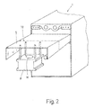
- This cooling air is supplied by a schematically indicated blower unit 8, which according to Fig. 2 is designed as a box-like module of limited size.
- the blower unit 8 comprises a motor (not shown) together with the fan (or a radial fan), as a result of the limited size, the motor can be of small size with low power consumption, which in turn requires at least two depending on the length of the elongated UV lamp but in some cases also several such blower units, which in turn ensures that the UV lamp is cooled quite uniformly and vigorously over its entire length without temperature gradients occurring along the lamp 3.
- the respective blower units 8 can each be inserted into the housing 1, as is the case Fig. 2 emerges showing a support plate 9, which is either equipped with several modules 8 or approximately along the dashed line 10 is divided, each module 8 is assigned a separate support plate 9.
- the presentation of the Fig. 1 is similar and shows two guide rails 11, in which a respective blower unit 8 via an approximately V-shaped cover plate 9a is inserted.
- the respective blower unit 8 is connected at its bottom directly with air guide means, in which case then the whole unit, for example, in grooves 12 of the housing 1 can be inserted.
- the whole unit for example, in grooves 12 of the housing 1 can be inserted.
- both the grooves 12 and the guide rails 11 are provided. In any case, one achieves such a simple, rapid and cost-effective installation.
- the above-mentioned air guide means comprise the channel 7, above which a deflecting body 13 is arranged, the coming of the fan 8 cooling air in two equally large channels deflects 14, but at the same time also ensures that the fan 8 is not directly exposed to the radiant heat of the UV lamp 3.
- This deflecting body preferably has a roof edge-like with the tip directed against the fan surface, so that there is a low flow resistance and the air is divided evenly into the channels 14.
- the deflecting body 13 is preferably hollow and, like the mentioned cooling channels 5, supplied with a coolant which flows either through the same cooling circuit as that of the channels 5 or through a separate cooling circuit.
- the relatively large space 17 available within a hollow baffle 13 may also be used to provide a vaporizable coolant, e.g. Freon, as used in refrigerators, to use.
- the cooling air, blown down from the fan 8 flows through the deflection channels 14 and into the channel 7.
- This channel 7, when not connected to the fan 8, can extend over the entire length of the UV lamp 3, in FIG In which case, however, its boundary walls must each be adapted to this length. If, however, the channel 7 part of the fan module or firmly connected to him, then here also eliminates the custom-made, because only one module 7, 8, 13, 14 etc. needs to be ranked on the other.
- the cooling air As soon as the cooling air has left the channel 7, it passes over the UV lamp 3 and along the surfaces of the reflector 4, at the bottom of which it exits. However, since the air has warmed in the course of this path, it has the tendency to ascend again after exiting the reflector 4, where the space of the housing 1 widens. The air inevitably flows at the top of the reflectors 4 (where the cooling channels 5 are) and along the side walls of the housing 1 (which may also be cooled with a cooling liquid if desired) between a cooling fin arrangement 15 of a heat exchanger having cooling channels 5 '.
- the cooling fins may be transverse to the plane of the drawing or in and parallel to the plane of the drawing Fig. 1 extend.
Abstract
Description
Die Erfindung bezieht sich auf eine Vorrichtung nach dem Oberbegriff des Anspruches 1. Eine derartige Vorrichtung ist beispielsweise aus der
Bei einer solchen Vorrichtung treten - trotz einer an sich recht intensiven Kühlung - zahlreiche Nachteile auf. Zum einen wird das Lampengehäuse in Längsrichtung mit Kühlluft durchströmt. Dies ergibt fraglos einen Temperaturgradienten über die Länge des Gehäuses, d.h. die Kühlluft tritt im wesentlichen kühl in das Gehäuse ein und wird im Laufe ihres Weges immer heisser. Zwar sind dazu auch noch Kühlkanäle vorgesehen, welche oberhalb der Lampe angeordnet sind, doch ist klar, dass auch diese Kühlkanäle durch die über den an ihnen anliegenden Reflektor aufgeheizt werden.In such a device occur - despite a rather intense cooling itself - numerous disadvantages. On the one hand, the lamp housing is flowed through in the longitudinal direction with cooling air. This undoubtedly gives rise to a temperature gradient across the length of the housing, i. the cooling air enters the housing substantially cool and becomes hotter as it progresses. Although this cooling channels are also provided, which are arranged above the lamp, but it is clear that these cooling channels are heated by the overlying them on the reflector.
Ein weiterer Nachteil liegt darin, dass die Kühlmittel von irgendwo von aussen zugeführt werden, was die Sache nicht kompakter macht. Vielmehr sind kräftige Gebläse bzw. Pumpen nötig, um die Kühlmittel im Umlauf zu halten. Das verteuert natürlich die gesamte Vorrichtung. Da die Kühlmittel im Umlauf geführt sind - wodurch das Abblasen der Kühlluft bzw. das Ablassen des Kühlwassers vermieden wird - muss eine weitere Kühleinrichtung vorgesehen sein, weil sonst ja das rückgeführte aufgeheizte Kühlgas (im letzten Teil seines Weges kann das Kühlfluid auch nicht mehr viel bewirken) als Heizmittel und nicht als Kühlmittel wirkte.Another disadvantage is that the coolants are supplied from somewhere outside, which does not make the thing more compact. Rather, powerful blowers or pumps are needed to keep the coolant in circulation. Of course, that makes the entire device more expensive. Since the coolant is circulated - whereby the blowing off of the cooling air or the discharge of the cooling water is avoided - a further cooling device must be provided, because otherwise the recycled heated cooling gas (in the last part of his path, the cooling fluid can not do much ) acted as a heating medium and not as a coolant.
Ausserdem ist diese Anordnung recht kompliziert, wenn man bedenkt, dass das Lampengehäuse die aufgesetzte Kühlung und auch noch die Luft- und Wasserversorgung trägt, welch letztere sogar in doppelter Form vorliegt. Diese Komplexizität des Aufbaues führt aber auch dazu, dass die Montage (Erstmontage, Reparaturmontage) schwierig und teuer wird.Moreover, this arrangement is quite complicated, bearing in mind that the lamp housing carries the patch cooling and also the air and water supply, the latter even being in duplicate. However, this complexity of the structure also leads to the fact that the assembly (initial assembly, repair assembly) is difficult and expensive.
Aus der
Auch ist eine ähnliche Konstruktion aus der
Es ist daher Aufgabe der Erfindung, eine Vorrichtung der eingangs genannten Art so auszubilden, dass eine einfachere, kostgünstigere und vor allem auch wirksamere Kühlung erreicht wird. Dies wird durch die kennzeichnenden Merkmale des Anspruches 1 erreicht.It is therefore an object of the invention to provide a device of the type mentioned in such a way that a simpler, more cost-effective and above all more effective cooling is achieved. This is achieved by the characterizing features of claim 1.
Zum Kühlen von UV-Lampen quer zur Längsachse - was also die Bildung von Temperaturgradienten weitgehend vermeidet- ist es beispielsweise aus der
Dies gilt analog auch für die Konstruktion nach der
Durch die Erfindung ergeben sich aber mehrere Vorteile:
- Vor allem ergeben sich über die Länge der Lampe praktisch keine Temperaturgradienten, weil überall gleichmässig gekühlt wird;
- da die Luftführung an den Wandungen des Reflektors vorbei und wieder zum Gebläse geführt wird, kann auch der Reflektor gekühlt werden, ohne etwa von Wandungen eines Mantelkanals abgeschirmt zu sein, doch weist dieser Reflektor vorzugsweise mindestens einen Kühlfluidkanal auf so, dass der Luftstrom weiter gekühlt wird;
- dabei ergibt sich damit ein ziemlich kompakter- und so auch kühlungswirksamer Aufbau;
- das Kühlgas strömt, vorzugsweise unter etwa 90° zur Lampenachse, um die Lampe und nimmt von ihr Wärme auf, wird aber gleich danach durch den - wie oben erläutert - vorzugsweise gekühlten Reflektor wieder etwas abgekühlt, d.h. durch die Fluidkühlung des Strahlkopfes kann die gesamte Kühlluft zum Kühlen der Lampe ausgenutzt werden;
- durch die Tatsache, dass Umluft (oder-gas) verwendet wird, ist die Gefahr gebannt, dass mit der Luft Staub in das Gehäuse eingetragen wird;
- durch die Strömungsführung des Kühlgases werden sich erweiternde Kammern vermieden, welche die Strömung im Warmbereich verlangsamen und dadurch den Abtransport der Wärme behindern;
- mit dem Druckgebläse kann also kühle Luft mit relativ hoher Geschwindigkeit an die Lampe gebracht werden, was beim Ansaugen der Luft durch ein über ihr gelegenes Gebläse nicht möglich wäre;
- als gesonderte Einheiten sind diese, z.B. für eine Reparatur, jederzeit leicht austauschbar.
- Above all, there are practically no temperature gradients over the length of the lamp because cooling is uniform everywhere;
- since the air duct is guided past the walls of the reflector and back to the blower, and the reflector can be cooled without being shielded by walls of a jacket channel, but this reflector preferably has at least one cooling fluid channel so that the air flow is further cooled ;
- this results in a rather compact and so cooling effective construction;
- the cooling gas flows, preferably at about 90 ° to the lamp axis, around the lamp and absorbs heat from it, but then immediately thereafter slightly cooled by the - as explained above - preferably cooled reflector, ie by the fluid cooling of the jet head, the entire cooling air be used to cool the lamp;
- the fact that circulating air (or gas) is used eliminates the risk of dust being introduced into the housing with the air;
- by the flow guidance of the cooling gas expanding chambers are avoided, which slow the flow in the warm area and thereby hinder the removal of heat;
- with the pressure fan so cool air can be brought to the lamp at a relatively high speed, which would not be possible when sucking in the air through a blower located above it;
- as separate units, these are easily replaceable at any time, eg for a repair.
Im Vergleich zum Stand der Technik erhält man überdies erfindungsgemäss zum Kühlen der UV-Lampe mindestens zwei quer zur Längsachse blasende Einheiten mit je einem Gebläse vorgesehen, d.h. die Blasleistung wird auf mindestens zwei Einheiten aufgeteilt, wobei die Einheiten kleinere und billigere Motoren haben können, die Kühlung vergleichmässigt wird und überdies ein modularer Aufbau, wie er insbesondere in Anspruch 2 unter Schutz gestellt ist, erleichtert wird.In comparison with the prior art, moreover, according to the invention, for cooling the UV lamp, at least two units blowing transversely to the longitudinal axis, each with a blower, are provided, that is to say in accordance with the invention. the blowing power is divided into at least two units, the units can have smaller and cheaper engines, the cooling is made uniform and also a modular structure, as provided in particular in
Ein solcher modularer Aufbau hat mehrere Vorteile, denn einerseits lassen sich mit der entsprechenden Anzahl von Gebläseeinheiten die unterschiedlichsten Längen von UV-Lampen gleichmässig kühlen, so dass auch in der Lagerhaltung ein Vorteil entsteht, denn es müssen nun nicht mehr je nach Grösse unterschiedliche Kühlaggregate bereitgestellt werden. Die bevorzugte Ausführung nach Anspruch 2 gestattet es zudem, die Montage dieser Einheiten rasch und kostengünstig zu gestalten.Such a modular design has several advantages, because on the one hand, with the appropriate number of fan units, the different lengths of UV lamps can cool evenly, so that an advantage also arises in the storage, because it no longer has to provide different cooling units depending on the size become. The preferred embodiment according to
Sind fluidgekühlte Flächen mit Kühlkanälen, gewissermassen als Wärmetauscher, am Wege des Kühlgases zwischen dem Ausgang des Reflektors und dem Gebläse vorgesehen, dann gelangt gekühlte Luft im Umlauf zum jeweiligen Gebläse, insbesondere einem Radialgebläse, so dass dieses einer geringeren Wärmebelastung unterliegt und die Luft für einen erneuten Kühlzyklus bereit gemacht wird.Are fluid-cooled surfaces with cooling channels, as a kind of heat exchanger, provided on the path of the cooling gas between the outlet of the reflector and the fan, then cooled air passes in circulation to the respective fan, in particular a radial fan, so that this is subject to a lower heat load and the air for a re-cooling cycle is made ready.
Obwohl es im Stande der Technik auch bekannt ist, die jeweilige Lampe von der Seite her mit Luft zu kühlen, ist es im Rahmen der Erfindung günstiger, wenn das jeweilige Gebläse oberhalb der Lampe angeordnet ist, weil dann wird der aus Lampe und Reflektor bestehende Strahlkopf gerade dort am mit kühler Luft versorgt und so am wirkungsvollsten gekühlt wird, wo sie am heissesten wirdAlthough it is also known in the art to cool the respective lamp from the side with air, it is cheaper in the invention, if the respective fan is arranged above the lamp, because then the existing lamp and reflector beam head it is supplied with cool air and cooled most effectively where it gets the hottest
Weitere Einzelheiten der Erfindung ergeben sich an Hand der nachfolgenden Beschreibung eines in der Zeichnung schematisch dargestellten Ausführungsbeispieles. Es zeigen:
- Fig. 1
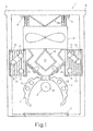
- zeigt ein erfindungsgemäss ausgebildetes UV-Lampengehäuse im Querschnitt; und
- Fig. 2
- veranschaulicht ein Detail einer abgewandelten Ausführungsform in Perspektive, wobei aus
Fig. 1 ersichtliche Teile, wie etwa die UV-durchlässige Platte weggelassen sind .
- Fig. 1
- shows a trained according to the invention UV lamp housing in cross section; and
- Fig. 2
- illustrates a detail of an alternative embodiment in perspective, wherein
Fig. 1 apparent parts, such as the UV-transmissive plate are omitted.
In
Das Gehäuse ist vollkommen geschlossen, denn die Bodenwand trägt eine UV-durchlässige Platte 2, um das Licht einer UV-Lampe 3 mit einer Längsachse A hindurchzulassen. Dazu ist die UV-Lampe 3 in bekannter Weise von einem aus zwei Teilen bestehenden - gegebenenfalls aber auch einteiligen oder mehrteiligen - Reflektor 4 umgeben. Der Reflektor selbst kann auch als sogenannter Shutter (beweglicher Lichtverschluss) ausgebildet sein, oder es kann ein gesonderter Shutter (nicht dargestellt) vorgesehen werden.The housing is completely closed, because the bottom wall carries a UV-
Innerhalb der Teile des Reflektors sind Kühlkanäle 5 für den Durchfluss einer Kühlflüssigkeit vorgesehen, die in an sich bekannter Weise von einem Flüssigkeitsvorrat mittels einer Pumpe (nicht dargestellt) hindurchgepumpt wird. Zweckmässig ist in diesem Kühlfluidkreislauf auch ein (nicht dargestellter Wärmetauscher vorgesehen, um die Flüssigkeit abzukühlen, anderseits aber auch die abgezogene Wärme einem nützlichen Zweck zuzuführen.Within the parts of the
Oberhalb der Lampe ist ein, beispielsweise schlitzförmiger, Kanal 7 vorgesehen, durch welchen Kühlluft auf die UV-Lampe 3 quer zu ihrer Achse A strömt. Diese Kühlluft wird von einem schematisch angedeuteten Gebläseaggregat 8 geliefert, welches gemäss
Die jeweiligen Gebläseaggregate 8 können jeweils für sich in das Gehäuse 1 eingeschoben werden, wie dies aus
Gerade der modulartige Aufbau der Kühlung erlaubt aber auch eine vereinfachte Lagerhaltung, weil es nun nicht mehr erforderlich ist, je nach Länge der Lampe 3 zugehörige unterschiedliche Kühlaggregate, Motoren etc. auf Lager zu haltenBut the modular design of the cooling but also allows a simplified storage, because it is no longer necessary, depending on the length of the lamp 3 associated different cooling units, motors, etc. to keep in stock
Alternativ allerdings ist das jeweilige Gebläseaggregat 8 an seiner Unterseite unmittelbar mit Luftführungseinrichtungen verbunden, in welchem Falle dann die ganze Einheit beispielsweise in Nuten 12 des Gehäuses 1 einschiebbar ist. Selbstverständlich sind auch Kombinationen denkbar, bei denen sowohl die Nuten 12 als auch die Führungsleisten 11 vorgesehen sind. In jedem Falle erreicht man so eine einfache, rasche und kostengünstige Montage.Alternatively, however, the
Die erwähnten Luftführungseinrichtungen umfassen den Kanal 7, oberhalb dessen ein Umlenkkörper 13 angeordnet ist, der die vom Gebläse 8 herkommende Kühlluft in zwei gleich grosse Kanäle 14 umlenkt, gleichzeitig aber auch dafür sorgt, dass das Gebläse 8 nicht unmittelbar der Strahlungswärme der UV-Lampe 3 ausgesetzt ist. Dieser Umlenkkörper hat vorzugsweise eine dachkantenartig mit der Spitze gegen das Gebläse gerichtete Fläche, so dass sich ein geringer Strömungswiderstand ergibt und die Luft gleichmässig in die Kanäle 14 aufgeteilt wird.The above-mentioned air guide means comprise the
Um die Wärme der UV-Lampe 3 zu absorbieren und abzuleiten, ist der Umlenkkörper 13 vorzugsweise hohl und ebenso wie die erwähnten Kühlkanäle 5 mit einem Kühlmittel versorgt, welches entweder über denselben Kühlkreislauf fliesst wie das der Kanäle 5 oder durch einen gesonderten Kühlkreislauf. Alternativ, kann der verhältnismässig grosse innerhalb eines hohlen Umlenkkörpers 13 zur Verfügung stehende Raum 17 auch dazu benutzt werden, ein verdampfbares Kühlmittel, z.B. Freon, wie es in Kühlschränken verwendet wird, einzusetzen.In order to absorb and dissipate the heat of the UV lamp 3, the deflecting
Somit wird die Kühlluft, vom Gebläse 8 abwärts geblasen, strömt durch die Umlenkkanäle 14 und in den Kanal 7. Dieser Kanal 7 kann, wenn er nicht mit dem Gebläse 8 verbunden ist, sich über die ganze Länge der UV-Lampe 3 erstrecken, in welchem Falle seine Begrenzungswände aber jeweils an diese Länge angepasst werden müssen. Ist dagegen der Kanal 7 Bestandteil des Gebläsemoduls bzw. mit ihm fest verbunden, dann entfällt auch hier die Einzelanfertigung, weil lediglich ein Modul 7, 8, 13, 14 etc. an den anderen gereiht zu werden braucht.Thus, the cooling air, blown down from the
Sobald die Kühlluft den Kanal 7 verlassen hat, streicht sie über die UV-Lampe 3 und entlang der Flächen des Reflektors 4, an dessen Unterseite sie austritt. Da sich die Luft im Verlaufe dieses Weges aber erwärmt hat, hat sie die Tendenz, nach dem Austritt aus dem Reflektor 4, wo sich der Raum des Gehäuses 1 weitet, wieder aufzusteigen. Dabei strömt die Luft zwangsläufig an der Oberseite der Reflektoren 4 (wo die Kühlkanäle 5 liegen) und entlang der Seitenwände des Gehäuses 1 (die gewünschtenfalls auch noch mit einer Kühlflüssigkeit gekühlt sein können) zwischen einer Kühlrippenanordnung 15 eines Wärmetauschers, welche Kühlkanäle 5' aufweist. Die Kühlrippen können sich quer zur Zeichnungsebene oder in und parallel zur Zeichnungsebene der
Sodann gelangt sie erst wieder zum Gebläseaggregat 8, wo sie über eine obere Öffnung 16 (
Claims (7)
Applications Claiming Priority (1)
| Application Number | Priority Date | Filing Date | Title |
|---|---|---|---|
| CH01880/08A CH700039A1 (en) | 2008-12-01 | 2008-12-01 | Device for irradiating a substrate |
Publications (3)
| Publication Number | Publication Date |
|---|---|
| EP2192366A2 true EP2192366A2 (en) | 2010-06-02 |
| EP2192366A3 EP2192366A3 (en) | 2014-01-01 |
| EP2192366B1 EP2192366B1 (en) | 2016-07-27 |
Family
ID=41723060
Family Applications (1)
| Application Number | Title | Priority Date | Filing Date |
|---|---|---|---|
| EP09171971.6A Active EP2192366B1 (en) | 2008-12-01 | 2009-10-01 | Device for radiating a substrate |
Country Status (2)
| Country | Link |
|---|---|
| EP (1) | EP2192366B1 (en) |
| CH (1) | CH700039A1 (en) |
Cited By (2)
| Publication number | Priority date | Publication date | Assignee | Title |
|---|---|---|---|---|
| WO2010106338A1 (en) * | 2009-03-19 | 2010-09-23 | Gew (Ec) Limited | Cooling system for ink curing apparatus |
| WO2019120353A1 (en) * | 2017-12-21 | 2019-06-27 | Gunther Ackermann | Apparatus for irradiating an object |
Citations (5)
| Publication number | Priority date | Publication date | Assignee | Title |
|---|---|---|---|---|
| US5094010A (en) | 1990-07-05 | 1992-03-10 | Amjo Infra-Red And Ultra-Violet Drying Systems, Inc. | Vented ultraviolet drying system for drying fiberglass resins in boat hulls and decks |
| US5945680A (en) | 1995-03-15 | 1999-08-31 | Niels Lang Mathiesen And Knud Andreasen | Method for activating photoinitiators in photosensitive substrates and an apparatus for curing such substrates |
| EP0830217B1 (en) | 1995-05-04 | 1999-11-24 | NÖLLE GmbH | Method and device for hardening a layer on a substrate |
| EP0985121B1 (en) | 1997-05-26 | 2003-09-10 | Bernhard Max Glaus | Device for exposing a substrate to uv rays and method for using this device |
| US6646278B1 (en) | 1999-04-13 | 2003-11-11 | Ist Metz Gmbh | Irradiating device |
Family Cites Families (11)
| Publication number | Priority date | Publication date | Assignee | Title |
|---|---|---|---|---|
| US3604500A (en) * | 1970-04-07 | 1971-09-14 | Integrated Dev And Mfg Co | Method of controlling fluorescent lamp output |
| JPS5132969U (en) * | 1974-09-03 | 1976-03-11 | ||
| US4419716A (en) * | 1983-01-03 | 1983-12-06 | Stephen Koo | Vapor proof housing assembly and system |
| US5323271A (en) * | 1992-11-24 | 1994-06-21 | Equestrian Co., Ltd. | Water- and air-cooled reflection mirror |
| US5861633A (en) * | 1997-08-04 | 1999-01-19 | Con-Trol-Cure, Inc. | Irradiator apparatus |
| FR2798187B1 (en) * | 1999-09-06 | 2002-02-01 | Christian Lumpp | ELECTROMAGNETIC IRRADIATION DEVICE HAVING COOLING MEANS |
| JP3846232B2 (en) * | 2000-12-08 | 2006-11-15 | ウシオ電機株式会社 | Circulating air cooling system for light irradiators |
| AU2003273789A1 (en) * | 2002-10-29 | 2004-05-25 | Knud Andreasen | Cooling of devices for uv hardening |
| US7077547B2 (en) * | 2004-07-29 | 2006-07-18 | Nordson Corporation | Shuttered lamp assembly and method of cooling the lamp assembly |
| JP4424296B2 (en) * | 2005-10-13 | 2010-03-03 | ウシオ電機株式会社 | UV irradiation equipment |
| GB2444328B (en) * | 2006-12-01 | 2010-06-09 | Gew | Cooling system for ink curing apparatus |
-
2008
- 2008-12-01 CH CH01880/08A patent/CH700039A1/en not_active Application Discontinuation
-
2009
- 2009-10-01 EP EP09171971.6A patent/EP2192366B1/en active Active
Patent Citations (5)
| Publication number | Priority date | Publication date | Assignee | Title |
|---|---|---|---|---|
| US5094010A (en) | 1990-07-05 | 1992-03-10 | Amjo Infra-Red And Ultra-Violet Drying Systems, Inc. | Vented ultraviolet drying system for drying fiberglass resins in boat hulls and decks |
| US5945680A (en) | 1995-03-15 | 1999-08-31 | Niels Lang Mathiesen And Knud Andreasen | Method for activating photoinitiators in photosensitive substrates and an apparatus for curing such substrates |
| EP0830217B1 (en) | 1995-05-04 | 1999-11-24 | NÖLLE GmbH | Method and device for hardening a layer on a substrate |
| EP0985121B1 (en) | 1997-05-26 | 2003-09-10 | Bernhard Max Glaus | Device for exposing a substrate to uv rays and method for using this device |
| US6646278B1 (en) | 1999-04-13 | 2003-11-11 | Ist Metz Gmbh | Irradiating device |
Cited By (2)
| Publication number | Priority date | Publication date | Assignee | Title |
|---|---|---|---|---|
| WO2010106338A1 (en) * | 2009-03-19 | 2010-09-23 | Gew (Ec) Limited | Cooling system for ink curing apparatus |
| WO2019120353A1 (en) * | 2017-12-21 | 2019-06-27 | Gunther Ackermann | Apparatus for irradiating an object |
Also Published As
| Publication number | Publication date |
|---|---|
| EP2192366B1 (en) | 2016-07-27 |
| CH700039A1 (en) | 2010-06-15 |
| EP2192366A3 (en) | 2014-01-01 |
Similar Documents
| Publication | Publication Date | Title |
|---|---|---|
| DE19733496B4 (en) | lamp assembly | |
| DE3811620C2 (en) | ||
| DE202006018205U1 (en) | Clothes dryer with a drum and a heat pump circuit comprising a condenser, a throttle, an evaporator and a compressor comprises an auxiliary heat exchanger between the condenser and the throttle | |
| DE102009056968B3 (en) | Air treatment device for use in heating, ventilation, or air conditioning system on vehicle roof of rail vehicle for passenger transportation, has returning air channel running towards part in longitudinal direction | |
| EP1547099B1 (en) | Radiation device and method for its operation | |
| DE102005030501A1 (en) | Drying device especially for drying saw wood has interconnected drying chambers with common flow generating unit for circulating drying air flow around inside of chambers, and heating device for heating drying air | |
| DE102012007707B4 (en) | Cooling unit for cabinet cooling | |
| EP2192366B1 (en) | Device for radiating a substrate | |
| EP3720716B1 (en) | Method for drying a substrate, dryer module for carrying out the method and dryer system | |
| DE4436713B4 (en) | Device for drying the surfaces of an object | |
| DE102012205870B3 (en) | Cooling arrangement for cooling of laser gas for gas laser system, has secondary cooling circuit with supplementary heat exchanger that is located for additional cooling of laser gas flowing from fan to resonator | |
| EP3678790B1 (en) | Irradiation tunnel for containers, and method for irradiating containers | |
| DE3317714A1 (en) | Drying apparatus for a moving web of material | |
| EP0985121B1 (en) | Device for exposing a substrate to uv rays and method for using this device | |
| DE102008016055A1 (en) | lamp arrangement | |
| DE102011009456A1 (en) | Ultraviolet-dryer for drying printing inks and other ultraviolet-photopolymerizable materials, has ultraviolet radiation head with irradiation unit having cylindrical tubular ultraviolet lamp | |
| DE102007035989A1 (en) | System for drying print medium on printing material has arrangement for applying pulsating gas flow arranged so gas guide channels are mutually adjacent in direction transverse to transport direction | |
| EP2684497A2 (en) | Hand dryer | |
| EP2589909A2 (en) | Device for heating or drying of elongated materials | |
| DE102021131796B3 (en) | Furnace system for heating laminated glass panes | |
| EP2166299A2 (en) | Web of material drying device | |
| DE10136501C1 (en) | Substrate heating device using electromagnetic radiation has cooling medium feed with integrated flow channel directing cooling medium onto substrate outside heated area | |
| DE102013207632A1 (en) | Plastic processing machine, in particular injection molding machine with a tempering device arranged in the region of the filling zone | |
| DE10257432B4 (en) | Air-cooled irradiation arrangement | |
| DE102020213189B4 (en) | Control cabinet with fan module |
Legal Events
| Date | Code | Title | Description |
|---|---|---|---|
| PUAI | Public reference made under article 153(3) epc to a published international application that has entered the european phase |
Free format text: ORIGINAL CODE: 0009012 |
|
| AK | Designated contracting states |
Kind code of ref document: A2 Designated state(s): AT BE BG CH CY CZ DE DK EE ES FI FR GB GR HR HU IE IS IT LI LT LU LV MC MK MT NL NO PL PT RO SE SI SK SM TR |
|
| AX | Request for extension of the european patent |
Extension state: AL BA RS |
|
| PUAL | Search report despatched |
Free format text: ORIGINAL CODE: 0009013 |
|
| AK | Designated contracting states |
Kind code of ref document: A3 Designated state(s): AT BE BG CH CY CZ DE DK EE ES FI FR GB GR HR HU IE IS IT LI LT LU LV MC MK MT NL NO PL PT RO SE SI SK SM TR |
|
| AX | Request for extension of the european patent |
Extension state: AL BA RS |
|
| RIC1 | Information provided on ipc code assigned before grant |
Ipc: F21V 29/02 20060101ALI20131126BHEP Ipc: F26B 3/28 20060101AFI20131126BHEP |
|
| 17P | Request for examination filed |
Effective date: 20140626 |
|
| RBV | Designated contracting states (corrected) |
Designated state(s): AT BE BG CH CY CZ DE DK EE ES FI FR GB GR HR HU IE IS IT LI LT LU LV MC MK MT NL NO PL PT RO SE SI SK SM TR |
|
| 17Q | First examination report despatched |
Effective date: 20150518 |
|
| RIC1 | Information provided on ipc code assigned before grant |
Ipc: F26B 3/28 20060101AFI20160229BHEP Ipc: B41F 23/04 20060101ALI20160229BHEP |
|
| GRAP | Despatch of communication of intention to grant a patent |
Free format text: ORIGINAL CODE: EPIDOSNIGR1 |
|
| INTG | Intention to grant announced |
Effective date: 20160421 |
|
| GRAS | Grant fee paid |
Free format text: ORIGINAL CODE: EPIDOSNIGR3 |
|
| GRAA | (expected) grant |
Free format text: ORIGINAL CODE: 0009210 |
|
| AK | Designated contracting states |
Kind code of ref document: B1 Designated state(s): AT BE BG CH CY CZ DE DK EE ES FI FR GB GR HR HU IE IS IT LI LT LU LV MC MK MT NL NO PL PT RO SE SI SK SM TR |
|
| REG | Reference to a national code |
Ref country code: GB Ref legal event code: FG4D Free format text: NOT ENGLISH |
|
| REG | Reference to a national code |
Ref country code: CH Ref legal event code: EP |
|
| REG | Reference to a national code |
Ref country code: AT Ref legal event code: REF Ref document number: 816132 Country of ref document: AT Kind code of ref document: T Effective date: 20160815 |
|
| REG | Reference to a national code |
Ref country code: IE Ref legal event code: FG4D Free format text: LANGUAGE OF EP DOCUMENT: GERMAN |
|
| REG | Reference to a national code |
Ref country code: DE Ref legal event code: R096 Ref document number: 502009012871 Country of ref document: DE |
|
| REG | Reference to a national code |
Ref country code: CH Ref legal event code: NV Representative=s name: PATWIL AG, CH |
|
| REG | Reference to a national code |
Ref country code: LT Ref legal event code: MG4D |
|
| REG | Reference to a national code |
Ref country code: NL Ref legal event code: MP Effective date: 20160727 |
|
| PG25 | Lapsed in a contracting state [announced via postgrant information from national office to epo] |
Ref country code: NL Free format text: LAPSE BECAUSE OF FAILURE TO SUBMIT A TRANSLATION OF THE DESCRIPTION OR TO PAY THE FEE WITHIN THE PRESCRIBED TIME-LIMIT Effective date: 20160727 Ref country code: IS Free format text: LAPSE BECAUSE OF FAILURE TO SUBMIT A TRANSLATION OF THE DESCRIPTION OR TO PAY THE FEE WITHIN THE PRESCRIBED TIME-LIMIT Effective date: 20161127 Ref country code: FI Free format text: LAPSE BECAUSE OF FAILURE TO SUBMIT A TRANSLATION OF THE DESCRIPTION OR TO PAY THE FEE WITHIN THE PRESCRIBED TIME-LIMIT Effective date: 20160727 Ref country code: HR Free format text: LAPSE BECAUSE OF FAILURE TO SUBMIT A TRANSLATION OF THE DESCRIPTION OR TO PAY THE FEE WITHIN THE PRESCRIBED TIME-LIMIT Effective date: 20160727 Ref country code: NO Free format text: LAPSE BECAUSE OF FAILURE TO SUBMIT A TRANSLATION OF THE DESCRIPTION OR TO PAY THE FEE WITHIN THE PRESCRIBED TIME-LIMIT Effective date: 20161027 Ref country code: LT Free format text: LAPSE BECAUSE OF FAILURE TO SUBMIT A TRANSLATION OF THE DESCRIPTION OR TO PAY THE FEE WITHIN THE PRESCRIBED TIME-LIMIT Effective date: 20160727 |
|
| PG25 | Lapsed in a contracting state [announced via postgrant information from national office to epo] |
Ref country code: PT Free format text: LAPSE BECAUSE OF FAILURE TO SUBMIT A TRANSLATION OF THE DESCRIPTION OR TO PAY THE FEE WITHIN THE PRESCRIBED TIME-LIMIT Effective date: 20161128 Ref country code: PL Free format text: LAPSE BECAUSE OF FAILURE TO SUBMIT A TRANSLATION OF THE DESCRIPTION OR TO PAY THE FEE WITHIN THE PRESCRIBED TIME-LIMIT Effective date: 20160727 Ref country code: SE Free format text: LAPSE BECAUSE OF FAILURE TO SUBMIT A TRANSLATION OF THE DESCRIPTION OR TO PAY THE FEE WITHIN THE PRESCRIBED TIME-LIMIT Effective date: 20160727 Ref country code: GR Free format text: LAPSE BECAUSE OF FAILURE TO SUBMIT A TRANSLATION OF THE DESCRIPTION OR TO PAY THE FEE WITHIN THE PRESCRIBED TIME-LIMIT Effective date: 20161028 Ref country code: BE Free format text: LAPSE BECAUSE OF NON-PAYMENT OF DUE FEES Effective date: 20161031 Ref country code: ES Free format text: LAPSE BECAUSE OF FAILURE TO SUBMIT A TRANSLATION OF THE DESCRIPTION OR TO PAY THE FEE WITHIN THE PRESCRIBED TIME-LIMIT Effective date: 20160727 Ref country code: LV Free format text: LAPSE BECAUSE OF FAILURE TO SUBMIT A TRANSLATION OF THE DESCRIPTION OR TO PAY THE FEE WITHIN THE PRESCRIBED TIME-LIMIT Effective date: 20160727 |
|
| PG25 | Lapsed in a contracting state [announced via postgrant information from national office to epo] |
Ref country code: RO Free format text: LAPSE BECAUSE OF FAILURE TO SUBMIT A TRANSLATION OF THE DESCRIPTION OR TO PAY THE FEE WITHIN THE PRESCRIBED TIME-LIMIT Effective date: 20160727 Ref country code: EE Free format text: LAPSE BECAUSE OF FAILURE TO SUBMIT A TRANSLATION OF THE DESCRIPTION OR TO PAY THE FEE WITHIN THE PRESCRIBED TIME-LIMIT Effective date: 20160727 |
|
| REG | Reference to a national code |
Ref country code: DE Ref legal event code: R097 Ref document number: 502009012871 Country of ref document: DE |
|
| PG25 | Lapsed in a contracting state [announced via postgrant information from national office to epo] |
Ref country code: BG Free format text: LAPSE BECAUSE OF FAILURE TO SUBMIT A TRANSLATION OF THE DESCRIPTION OR TO PAY THE FEE WITHIN THE PRESCRIBED TIME-LIMIT Effective date: 20161027 Ref country code: CZ Free format text: LAPSE BECAUSE OF FAILURE TO SUBMIT A TRANSLATION OF THE DESCRIPTION OR TO PAY THE FEE WITHIN THE PRESCRIBED TIME-LIMIT Effective date: 20160727 Ref country code: DK Free format text: LAPSE BECAUSE OF FAILURE TO SUBMIT A TRANSLATION OF THE DESCRIPTION OR TO PAY THE FEE WITHIN THE PRESCRIBED TIME-LIMIT Effective date: 20160727 Ref country code: SM Free format text: LAPSE BECAUSE OF FAILURE TO SUBMIT A TRANSLATION OF THE DESCRIPTION OR TO PAY THE FEE WITHIN THE PRESCRIBED TIME-LIMIT Effective date: 20160727 Ref country code: SK Free format text: LAPSE BECAUSE OF FAILURE TO SUBMIT A TRANSLATION OF THE DESCRIPTION OR TO PAY THE FEE WITHIN THE PRESCRIBED TIME-LIMIT Effective date: 20160727 |
|
| PLBE | No opposition filed within time limit |
Free format text: ORIGINAL CODE: 0009261 |
|
| STAA | Information on the status of an ep patent application or granted ep patent |
Free format text: STATUS: NO OPPOSITION FILED WITHIN TIME LIMIT |
|
| 26N | No opposition filed |
Effective date: 20170502 |
|
| REG | Reference to a national code |
Ref country code: IE Ref legal event code: MM4A |
|
| REG | Reference to a national code |
Ref country code: FR Ref legal event code: ST Effective date: 20170630 |
|
| PG25 | Lapsed in a contracting state [announced via postgrant information from national office to epo] |
Ref country code: FR Free format text: LAPSE BECAUSE OF NON-PAYMENT OF DUE FEES Effective date: 20161102 |
|
| PG25 | Lapsed in a contracting state [announced via postgrant information from national office to epo] |
Ref country code: LU Free format text: LAPSE BECAUSE OF NON-PAYMENT OF DUE FEES Effective date: 20161001 Ref country code: SI Free format text: LAPSE BECAUSE OF FAILURE TO SUBMIT A TRANSLATION OF THE DESCRIPTION OR TO PAY THE FEE WITHIN THE PRESCRIBED TIME-LIMIT Effective date: 20160727 |
|
| PG25 | Lapsed in a contracting state [announced via postgrant information from national office to epo] |
Ref country code: IE Free format text: LAPSE BECAUSE OF NON-PAYMENT OF DUE FEES Effective date: 20161001 |
|
| REG | Reference to a national code |
Ref country code: BE Ref legal event code: MM Effective date: 20161031 |
|
| REG | Reference to a national code |
Ref country code: AT Ref legal event code: MM01 Ref document number: 816132 Country of ref document: AT Kind code of ref document: T Effective date: 20161001 |
|
| PG25 | Lapsed in a contracting state [announced via postgrant information from national office to epo] |
Ref country code: AT Free format text: LAPSE BECAUSE OF NON-PAYMENT OF DUE FEES Effective date: 20161001 |
|
| PG25 | Lapsed in a contracting state [announced via postgrant information from national office to epo] |
Ref country code: CY Free format text: LAPSE BECAUSE OF FAILURE TO SUBMIT A TRANSLATION OF THE DESCRIPTION OR TO PAY THE FEE WITHIN THE PRESCRIBED TIME-LIMIT Effective date: 20160727 Ref country code: HU Free format text: LAPSE BECAUSE OF FAILURE TO SUBMIT A TRANSLATION OF THE DESCRIPTION OR TO PAY THE FEE WITHIN THE PRESCRIBED TIME-LIMIT; INVALID AB INITIO Effective date: 20091001 |
|
| PG25 | Lapsed in a contracting state [announced via postgrant information from national office to epo] |
Ref country code: MK Free format text: LAPSE BECAUSE OF FAILURE TO SUBMIT A TRANSLATION OF THE DESCRIPTION OR TO PAY THE FEE WITHIN THE PRESCRIBED TIME-LIMIT Effective date: 20160727 Ref country code: MC Free format text: LAPSE BECAUSE OF FAILURE TO SUBMIT A TRANSLATION OF THE DESCRIPTION OR TO PAY THE FEE WITHIN THE PRESCRIBED TIME-LIMIT Effective date: 20160727 Ref country code: TR Free format text: LAPSE BECAUSE OF FAILURE TO SUBMIT A TRANSLATION OF THE DESCRIPTION OR TO PAY THE FEE WITHIN THE PRESCRIBED TIME-LIMIT Effective date: 20160727 Ref country code: MT Free format text: LAPSE BECAUSE OF FAILURE TO SUBMIT A TRANSLATION OF THE DESCRIPTION OR TO PAY THE FEE WITHIN THE PRESCRIBED TIME-LIMIT Effective date: 20160727 |
|
| REG | Reference to a national code |
Ref country code: CH Ref legal event code: NV Representative=s name: KAMINSKI HARMANN PATENTANWAELTE AG, CH |
|
| PGFP | Annual fee paid to national office [announced via postgrant information from national office to epo] |
Ref country code: GB Payment date: 20231023 Year of fee payment: 15 |
|
| PGFP | Annual fee paid to national office [announced via postgrant information from national office to epo] |
Ref country code: IT Payment date: 20231030 Year of fee payment: 15 Ref country code: DE Payment date: 20231030 Year of fee payment: 15 Ref country code: CH Payment date: 20231102 Year of fee payment: 15 |