EP2189349A2 - Method and device for compensating a roll angle - Google Patents
Method and device for compensating a roll angle Download PDFInfo
- Publication number
- EP2189349A2 EP2189349A2 EP09175393A EP09175393A EP2189349A2 EP 2189349 A2 EP2189349 A2 EP 2189349A2 EP 09175393 A EP09175393 A EP 09175393A EP 09175393 A EP09175393 A EP 09175393A EP 2189349 A2 EP2189349 A2 EP 2189349A2
- Authority
- EP
- European Patent Office
- Prior art keywords
- image
- determined
- model
- displacement vectors
- camera
- Prior art date
- Legal status (The legal status is an assumption and is not a legal conclusion. Google has not performed a legal analysis and makes no representation as to the accuracy of the status listed.)
- Withdrawn
Links
- 238000000034 method Methods 0.000 title claims abstract description 18
- 239000013598 vector Substances 0.000 claims abstract description 93
- 238000006073 displacement reaction Methods 0.000 claims abstract description 57
- 238000003384 imaging method Methods 0.000 claims description 4
- 230000001419 dependent effect Effects 0.000 claims description 2
- 238000003702 image correction Methods 0.000 claims description 2
- 238000010191 image analysis Methods 0.000 description 3
- 239000011159 matrix material Substances 0.000 description 3
- 238000012545 processing Methods 0.000 description 3
- 238000013519 translation Methods 0.000 description 2
- 238000004458 analytical method Methods 0.000 description 1
- 238000013459 approach Methods 0.000 description 1
- 238000010276 construction Methods 0.000 description 1
- 238000012937 correction Methods 0.000 description 1
- 238000001514 detection method Methods 0.000 description 1
- 238000013507 mapping Methods 0.000 description 1
- 230000007704 transition Effects 0.000 description 1
Images

Classifications
-
- B—PERFORMING OPERATIONS; TRANSPORTING
- B60—VEHICLES IN GENERAL
- B60W—CONJOINT CONTROL OF VEHICLE SUB-UNITS OF DIFFERENT TYPE OR DIFFERENT FUNCTION; CONTROL SYSTEMS SPECIALLY ADAPTED FOR HYBRID VEHICLES; ROAD VEHICLE DRIVE CONTROL SYSTEMS FOR PURPOSES NOT RELATED TO THE CONTROL OF A PARTICULAR SUB-UNIT
- B60W40/00—Estimation or calculation of non-directly measurable driving parameters for road vehicle drive control systems not related to the control of a particular sub unit, e.g. by using mathematical models
- B60W40/10—Estimation or calculation of non-directly measurable driving parameters for road vehicle drive control systems not related to the control of a particular sub unit, e.g. by using mathematical models related to vehicle motion
- B60W40/11—Pitch movement
-
- B—PERFORMING OPERATIONS; TRANSPORTING
- B60—VEHICLES IN GENERAL
- B60W—CONJOINT CONTROL OF VEHICLE SUB-UNITS OF DIFFERENT TYPE OR DIFFERENT FUNCTION; CONTROL SYSTEMS SPECIALLY ADAPTED FOR HYBRID VEHICLES; ROAD VEHICLE DRIVE CONTROL SYSTEMS FOR PURPOSES NOT RELATED TO THE CONTROL OF A PARTICULAR SUB-UNIT
- B60W40/00—Estimation or calculation of non-directly measurable driving parameters for road vehicle drive control systems not related to the control of a particular sub unit, e.g. by using mathematical models
- B60W40/10—Estimation or calculation of non-directly measurable driving parameters for road vehicle drive control systems not related to the control of a particular sub unit, e.g. by using mathematical models related to vehicle motion
- B60W40/105—Speed
-
- B—PERFORMING OPERATIONS; TRANSPORTING
- B60—VEHICLES IN GENERAL
- B60W—CONJOINT CONTROL OF VEHICLE SUB-UNITS OF DIFFERENT TYPE OR DIFFERENT FUNCTION; CONTROL SYSTEMS SPECIALLY ADAPTED FOR HYBRID VEHICLES; ROAD VEHICLE DRIVE CONTROL SYSTEMS FOR PURPOSES NOT RELATED TO THE CONTROL OF A PARTICULAR SUB-UNIT
- B60W40/00—Estimation or calculation of non-directly measurable driving parameters for road vehicle drive control systems not related to the control of a particular sub unit, e.g. by using mathematical models
- B60W40/10—Estimation or calculation of non-directly measurable driving parameters for road vehicle drive control systems not related to the control of a particular sub unit, e.g. by using mathematical models related to vehicle motion
- B60W40/112—Roll movement
-
- B—PERFORMING OPERATIONS; TRANSPORTING
- B60—VEHICLES IN GENERAL
- B60W—CONJOINT CONTROL OF VEHICLE SUB-UNITS OF DIFFERENT TYPE OR DIFFERENT FUNCTION; CONTROL SYSTEMS SPECIALLY ADAPTED FOR HYBRID VEHICLES; ROAD VEHICLE DRIVE CONTROL SYSTEMS FOR PURPOSES NOT RELATED TO THE CONTROL OF A PARTICULAR SUB-UNIT
- B60W40/00—Estimation or calculation of non-directly measurable driving parameters for road vehicle drive control systems not related to the control of a particular sub unit, e.g. by using mathematical models
- B60W40/10—Estimation or calculation of non-directly measurable driving parameters for road vehicle drive control systems not related to the control of a particular sub unit, e.g. by using mathematical models related to vehicle motion
- B60W40/114—Yaw movement
-
- G—PHYSICS
- G06—COMPUTING; CALCULATING OR COUNTING
- G06V—IMAGE OR VIDEO RECOGNITION OR UNDERSTANDING
- G06V20/00—Scenes; Scene-specific elements
- G06V20/50—Context or environment of the image
- G06V20/56—Context or environment of the image exterior to a vehicle by using sensors mounted on the vehicle
- G06V20/58—Recognition of moving objects or obstacles, e.g. vehicles or pedestrians; Recognition of traffic objects, e.g. traffic signs, traffic lights or roads
-
- G—PHYSICS
- G06—COMPUTING; CALCULATING OR COUNTING
- G06V—IMAGE OR VIDEO RECOGNITION OR UNDERSTANDING
- G06V20/00—Scenes; Scene-specific elements
- G06V20/50—Context or environment of the image
- G06V20/56—Context or environment of the image exterior to a vehicle by using sensors mounted on the vehicle
- G06V20/588—Recognition of the road, e.g. of lane markings; Recognition of the vehicle driving pattern in relation to the road
-
- B—PERFORMING OPERATIONS; TRANSPORTING
- B60—VEHICLES IN GENERAL
- B60G—VEHICLE SUSPENSION ARRANGEMENTS
- B60G2400/00—Indexing codes relating to detected, measured or calculated conditions or factors
- B60G2400/05—Attitude
- B60G2400/051—Angle
- B60G2400/0511—Roll angle
-
- B—PERFORMING OPERATIONS; TRANSPORTING
- B60—VEHICLES IN GENERAL
- B60G—VEHICLE SUSPENSION ARRANGEMENTS
- B60G2401/00—Indexing codes relating to the type of sensors based on the principle of their operation
- B60G2401/14—Photo or light sensitive means, e.g. Infrared
- B60G2401/142—Visual Display Camera, e.g. LCD
-
- B—PERFORMING OPERATIONS; TRANSPORTING
- B60—VEHICLES IN GENERAL
- B60T—VEHICLE BRAKE CONTROL SYSTEMS OR PARTS THEREOF; BRAKE CONTROL SYSTEMS OR PARTS THEREOF, IN GENERAL; ARRANGEMENT OF BRAKING ELEMENTS ON VEHICLES IN GENERAL; PORTABLE DEVICES FOR PREVENTING UNWANTED MOVEMENT OF VEHICLES; VEHICLE MODIFICATIONS TO FACILITATE COOLING OF BRAKES
- B60T2230/00—Monitoring, detecting special vehicle behaviour; Counteracting thereof
- B60T2230/03—Overturn, rollover
-
- B—PERFORMING OPERATIONS; TRANSPORTING
- B60—VEHICLES IN GENERAL
- B60W—CONJOINT CONTROL OF VEHICLE SUB-UNITS OF DIFFERENT TYPE OR DIFFERENT FUNCTION; CONTROL SYSTEMS SPECIALLY ADAPTED FOR HYBRID VEHICLES; ROAD VEHICLE DRIVE CONTROL SYSTEMS FOR PURPOSES NOT RELATED TO THE CONTROL OF A PARTICULAR SUB-UNIT
- B60W2420/00—Indexing codes relating to the type of sensors based on the principle of their operation
- B60W2420/40—Photo or light sensitive means, e.g. infrared sensors
- B60W2420/403—Image sensing, e.g. optical camera
-
- B—PERFORMING OPERATIONS; TRANSPORTING
- B60—VEHICLES IN GENERAL
- B60W—CONJOINT CONTROL OF VEHICLE SUB-UNITS OF DIFFERENT TYPE OR DIFFERENT FUNCTION; CONTROL SYSTEMS SPECIALLY ADAPTED FOR HYBRID VEHICLES; ROAD VEHICLE DRIVE CONTROL SYSTEMS FOR PURPOSES NOT RELATED TO THE CONTROL OF A PARTICULAR SUB-UNIT
- B60W2520/00—Input parameters relating to overall vehicle dynamics
- B60W2520/18—Roll
-
- B—PERFORMING OPERATIONS; TRANSPORTING
- B60—VEHICLES IN GENERAL
- B60W—CONJOINT CONTROL OF VEHICLE SUB-UNITS OF DIFFERENT TYPE OR DIFFERENT FUNCTION; CONTROL SYSTEMS SPECIALLY ADAPTED FOR HYBRID VEHICLES; ROAD VEHICLE DRIVE CONTROL SYSTEMS FOR PURPOSES NOT RELATED TO THE CONTROL OF A PARTICULAR SUB-UNIT
- B60W2720/00—Output or target parameters relating to overall vehicle dynamics
- B60W2720/18—Roll
Definitions
- the invention relates to a method and a device for compensating a roll angle during operation of a camera-assisted driver assistance system in a motor vehicle.
- Modern driver assistance systems are regularly coupled with cameras and are supported by means of image processing of the images taken by the camera.
- the cameras detect speed limits and / or lane markings.
- a lane departure warning system analyzes the images taken by the camera for lane markings and alerts the driver of the motor vehicle if it overruns the lane markings delimiting the road.
- the driver assistance system and / or the image processing system knows the exact orientation of the camera with respect to the roadway. It is particularly advantageous if an image perpendicular to a lower edge of the captured images is parallel to a surface normal on the road. Alternatively, it is sufficient if an angle between the surface normal of the road surface and the image normal is known, so that this angle can be taken into account in the image analysis.
- the angle between the surface normal of the road surface and the image normal in the image plane of the camera can be at a flat road, for example, due to an imprecise built-in camera, due to a tank filling due to uneven loading of the motor vehicle and / or due to an uneven distribution of persons in the motor vehicle.
- the angle corresponds seen in the direction of travel a roll angle of the motor vehicle and is referred to in this context below as a roll angle.
- the invention is characterized by a method and a device for compensating a roll angle when operating a camera-based driver assistance system in a motor vehicle.
- a first image is acquired with the aid of a camera of the motor vehicle and the coordinates of at least two characteristic points of the first image are determined.
- a second image is acquired with the aid of the camera and the coordinates of the two characteristic points in the second image are determined.
- two displacement vectors are determined which are each representative of a displacement of the characteristic points in an image plane of the camera, in particular from the first image to the second image.
- two model displacement vectors are determined, each of which model the displacement of the characteristic points in the image plane.
- a reference vector is determined.
- the roll angle is determined.
- the images may be the same as full images captured by the camera or only parts of it. Furthermore, the images are preferably detected in the direction of travel of the motor vehicle. The movement of the motor vehicle between the recording of the first and the second image is preferably characterized by a speed of the motor vehicle.
- the reference vector is a model normal vector which is perpendicular to the road surface and thus corresponds to a surface normal of the roadway.
- the roll angle is preferably determined by projecting the model normal vector onto the image plane and comparing the projected model normal vector with an image perpendicular in the image plane of the camera. The roll angle in this context corresponds to the angle between the projected model normal vector and the image normal.
- three or more actual displacement vectors and correspondingly three or more model displacement vectors are determined, from which then the model normal vector is determined.
- This can be a mathematical system of equations be determined to determine the model normal vector, which may contribute to a particularly precise determination of the model normal vector.
- At least one of the actual displacement vectors is discarded and not considered further, in particular the actual displacement vector whose angular deviation from the one or more averaged vectors is greatest. This can help to exclude incorrectly determined actual displacement vectors and not to be taken into account in the determination of the model displacement vectors and the model normal vector and thus contributes to the particularly precise determination of the model normal vector.
- the model displacement vectors are dependent on the coordinates of the model normal vector.
- the model normal vector is determined by minimizing, by varying the coordinates of the model normal vector, a function value of a function corresponding to a distinction between all the considered actual displacement vectors and the corresponding model displacement vectors. This contributes to the fact that the model normal vector is determined with a particularly low application cost.
- the difference between the actual displacement vectors and the corresponding model displacement vectors may be expressed, for example, by an amount of the differences of the related vectors and then adding up all the amounts.
- the model normal vector corresponds optimally to the surface normal on the road surface if and only if the function value is minimal.
- the determined roll angle is used for image correction of the camera image.
- the determined roll angle can be automatically made available to the driver assistance system. This contributes to a precise functioning of the driver assistance system and thus to the safety of the driver of the motor vehicle.
- model displacement vectors are determined by means of the general equation of motion, the mapping equation of a pinhole camera and the general plane equation. This also contributes to the low application effort when programming the method.
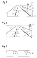
- FIG. 1 shows a road 20 with lane markings 24.
- the road 20 is visible to a horizon 26.
- a traffic sign 28 can be seen.
- a camera in particular a monocamera, which is arranged in a motor vehicle
- a first image 32 is preferably recorded in the direction of travel of the motor vehicle.
- characteristic points 30 are searched for by means of an image recognition system.
- the image recognition system may, for example, have a corner finder which searches for characteristic points 30 on the road 20 on the basis of distinctive gray value transitions.
- characteristic points 30 are preferably sought, which have the greatest possible distance from one another.
- FIG. 2 shows a view of the road 20 shortly after taking the first image 32.
- a second image 33 is taken by the camera.
- the image recognition system searches again for the characteristic points 30, which are now shifted relative to the first image 32 due to an interim movement of the motor vehicle in the second image 33.
- an image analysis system may determine first to fourth actual displacement vectors IV_1 to IV_4 representative of the displacement of the characteristic points 30 in the image plane of the camera between the capture of the first image 32 and the acquisition of the second image 33 more actual displacement vectors IV_1 to IV_4 determined.
- one or more of the actual displacement vectors IV_1 to IV_4 can also be discarded after their determination, for example if they have an angle which deviates greatly from one or more averaged angles of the other actual displacement vectors IV_1 to IV_4. This avoids that incorrectly determined actual displacement vectors IV_1 to IV_4 are taken into account in the further calculation.
- model displacement vectors MV_N Based on the coordinates of the characteristic points 30 of the first image 32, in addition to the actual displacement vectors IV_1 to IV_4 model displacement vectors MV_N based on the in FIG. 4 shown formulas F1 to F4 determined.
- the determination of the model displacement vectors MV_N is only briefly outlined below.
- the formulas F2 and F3 show a relationship between two-dimensional coordinates u 1 and u 2 , for example, one of the characteristic points 30, in the image plane of the camera and corresponding three-dimensional coordinates p 1 , p 2 , p 3 , for example, the corresponding characteristic point 30 the real roadway.
- the formulas F2 and F3 are basically also referred to as imaging equations of a pinhole camera. On the basis of the imaging equations of the lock camera, the three-dimensional ones can thus be determined starting from the characteristic points 30 recorded in the first image 32 Coordinates are determined in reality.
- R denotes a rotation matrix and t a translation vector, which depend on a movement of the motor vehicle.
- the rotation matrix R is simplified into a unit matrix and the translation vector has only one non-zero component and which depends on the speed of the motor vehicle.
- the three-dimensional coordinates q 1 , q 2 , q 3 , of the characteristic points 30 after the movement of the motor vehicle between the recording of the first image 32 and the recording of the second image 33 can be determined.
- the general plane equation is shown satisfying all points of a plane, where b 1 to b 3 are the coordinates of the normal vector of the corresponding plane.
- the model displacement vectors MV_N which are representative of the displacement of the characteristic points 30 from the first to the second image 32, 33 can now be determined as a function of a model normal vector b about the displacement of the characteristic points 30 in reality in dependence of the movement of the motor vehicle.
- the displacement of the characteristic points 30 between the images of the images 32, 33 on the one hand determined by simply measuring in the image plane, which the actual displacement vectors IV_N and on the other hand by determining the real displacement of the characteristic points 30 on the real roadway relative to the motor vehicle and transformed to the image plane.
- the displacement of the characteristic points 30 due to the movement of the motor vehicle is determined in two different ways.
- a function according to formula F5 now represents the sum over the amounts of the differences of all model displacement vectors MV_N and actual displacement vectors IV_N. If this sum is minimal, then the model displacement vectors MV_N correspond particularly well to the actual displacement vectors. Furthermore, the sum can be minimized by varying the model normal vector b. Therefore, it is assumed that the model normal vector b corresponds to the actual normal vector on the road, especially the road 20, when the sum is minimum. In other words, the model displacement vectors MV_N are varied by variation of the model normal vector b until they correspond as closely as possible to the actual displacement vectors IV_N. Preferably, so many displacement vectors are determined on the basis of the two or more images and on the represented model that the equation according to the formula F5 is strongly overdetermined. This allows a particularly precise approach to the actual normal vector of the road surface.
- FIG. 5 schematically shows a projection of the determined model normal vector b on the screen level.
- the projected model normal vector b concludes with an image vertical 40 which is perpendicular to a lower image edge of the image plane 36 an angle, in particular the roll angle ⁇ .
- this can now be considered in the image analysis system and the image be rotated accordingly.
- the image is not changed, but the determined roll angle .alpha. Is made available to the driver assistance system and / or further vehicle systems, so that they can directly take into account, in particular compensate, the roll angle .alpha.
Abstract
Description
Die Erfindung betrifft ein Verfahren und eine Vorrichtung zur Kompensation eines Rollwinkels beim Betrieb eines kameragestützten Fahrerassistenzsystems in einem Kraftfahrzeug.The invention relates to a method and a device for compensating a roll angle during operation of a camera-assisted driver assistance system in a motor vehicle.
Moderne Fahrerassistenzsysteme werden regelmäßig mit Kameras gekoppelt und werden mittels Bildverarbeitung der von der Kamera aufgenommenen Bilder unterstützt. Beispielsweise erkennen die Kameras Geschwindigkeitsbegrenzungen und/oder Fahrbahnmarkierungen. Insbesondere ein Spurhalteassistent analysiert die von der Kamera aufgenommenen Bilder nach Fahrbahnmarkierungen und alarmiert den Fahrer des Kraftfahrzeugs, falls dieser die die Straße begrenzenden Fahrbahnmarkierungen überfährt.Modern driver assistance systems are regularly coupled with cameras and are supported by means of image processing of the images taken by the camera. For example, the cameras detect speed limits and / or lane markings. In particular, a lane departure warning system analyzes the images taken by the camera for lane markings and alerts the driver of the motor vehicle if it overruns the lane markings delimiting the road.
Für eine präzise Analyse der Bilder der Kamera ist es vorteilhaft, wenn das Fahrerassistenzsystem und/oder das Bildverarbeitungssystem die genaue Ausrichtung der Kamera bezüglich der Fahrbahn kennt. Dabei ist es insbesondere vorteilhaft, wenn eine Bildsenkrechte auf einer unteren Kante der erfassten Bilder parallel zu einer Flächennormalen auf der Fahrbahn ist. Alternativ dazu ist es ausreichend, wenn ein Winkel zwischen der Flächennormalen der Fahrbahn und der Bildsenkrechten bekannt ist, so dass dieser Winkel bei der Bildanalyse berücksichtigt werden kann.For a precise analysis of the images of the camera, it is advantageous if the driver assistance system and / or the image processing system knows the exact orientation of the camera with respect to the roadway. It is particularly advantageous if an image perpendicular to a lower edge of the captured images is parallel to a surface normal on the road. Alternatively, it is sufficient if an angle between the surface normal of the road surface and the image normal is known, so that this angle can be taken into account in the image analysis.
Der Winkel zwischen der Flächennormalen der Fahrbahn und der Bildsenkrechten in der Bildebene der Kamera kann sich bei einer ebenen Fahrbahn beispielsweise auf Grund einer unpräzisen eingebauten Kamera, auf Grund einer Tankbefüllung, auf Grund einer ungleichmäßigen Beladung des Kraftfahrzeugs und/oder auf Grund einer ungleichmäßigen Verteilung von Personen in dem Kraftfahrzeug ergeben. Der Winkel entspricht in Fahrtrichtung gesehen einem Rollwinkel des Kraftfahrzeugs und wird in diesem Zusammenhang nachfolgend als Rollwinkel bezeichnet.The angle between the surface normal of the road surface and the image normal in the image plane of the camera can be at a flat road, for example, due to an imprecise built-in camera, due to a tank filling due to uneven loading of the motor vehicle and / or due to an uneven distribution of persons in the motor vehicle. The angle corresponds seen in the direction of travel a roll angle of the motor vehicle and is referred to in this context below as a roll angle.
Es ist Aufgabe der vorliegenden Erfindung, ein Verfahren und eine Vorrichtung zur Kompensation eines Rollwinkels beim Betrieb eines kameragestützten Fahrerassistenzsystems zu schaffen, die einfach und präzise die Kompensation des Rollwinkels ermöglichen.It is an object of the present invention to provide a method and a device for compensating a roll angle in the operation of a camera-based driver assistance system, which allow easy and precise compensation of the roll angle.
Die Aufgabe wird gelöst durch die Merkmale der unabhängigen Ansprüche. Vorteilhafte Ausgestaltungen sind in den Unteransprüchen angegeben.The object is solved by the features of the independent claims. Advantageous embodiments are specified in the subclaims.
Die Erfindung zeichnet sich aus durch ein Verfahren und eine Vorrichtung zur Kompensation eines Rollwinkels beim Betrieb eines kameragestützten Fahrerassistenzsystems in einem Kraftfahrzeug. Dabei wird mit Hilfe einer Kamera des Kraftfahrzeugs ein erstes Bild erfasst und die Koordinaten zumindest zweier charakteristischer Punkte des ersten Bildes werden ermittelt. Danach wird mit Hilfe der Kamera ein zweites Bild erfasst und es werden die Koordinaten der beiden charakteristischen Punkte in dem zweiten Bild ermittelt. Abhängig von den ermittelten Koordinaten der charakteristischen Punkte in dem ersten und dem zweiten Bild werden zwei Verschiebungsvektoren ermittelt, die jeweils repräsentativ sind für eine Verschiebung der charakteristischen Punkte in einer Bildebene der Kamera, insbesondere von dem ersten Bild hin zu dem zweiten Bild. Abhängig von den ermittelten Koordinaten der charakteristischen Punkte des ersten Bildes und abhängig von einer Bewegung des Kraftfahrzeugs zwischen der Aufnahme des ersten Bildes und der Aufnahme des zweiten Bildes werden zwei Modell-Verschiebungsvektoren ermittelt, die jeweils die Verschiebung der charakteristischen Punkte in der Bildebene modellieren. Abhängig von den ermittelten Ist-Verschiebungsvektoren und Modell-Verschiebungsvektoren wird ein Referenzvektor ermittelt. Abhängig von dem ermittelten Referenzvektor wird der Rollwinkel ermittelt.The invention is characterized by a method and a device for compensating a roll angle when operating a camera-based driver assistance system in a motor vehicle. In this case, a first image is acquired with the aid of a camera of the motor vehicle and the coordinates of at least two characteristic points of the first image are determined. Thereafter, a second image is acquired with the aid of the camera and the coordinates of the two characteristic points in the second image are determined. Depending on the determined coordinates of the characteristic points in the first and the second image, two displacement vectors are determined which are each representative of a displacement of the characteristic points in an image plane of the camera, in particular from the first image to the second image. Depending on the determined coordinates of the characteristic points of the first image and depending on a movement of the motor vehicle between the acquisition of the first image and the recording of the second image, two model displacement vectors are determined, each of which model the displacement of the characteristic points in the image plane. Depending on the determined actual displacement vectors and model displacement vectors, a reference vector is determined. Depending on the determined reference vector, the roll angle is determined.
Dies ermöglicht einfach und präzise den Rollwinkel zu kompensieren, insbesondere bei geringem Applikationsaufwand und ohne zusätzliche Sensorik. Die Bilder können vollständigen von der Kamera erfassten Bildern entsprechen oder nur Teilen davon. Ferner werden die Bilder vorzugsweise in Fahrtrichtung des Kraftfahrzeugs erfasst. Die Bewegung des Kraftfahrzeugs zwischen der Aufnahme des ersten und des zweiten Bildes ist vorzugsweise charakterisiert durch eine Geschwindigkeit des Kraftfahrzeugs.This makes it easy and precise to compensate for the roll angle, especially with low application costs and without additional sensors. The images may be the same as full images captured by the camera or only parts of it. Furthermore, the images are preferably detected in the direction of travel of the motor vehicle. The movement of the motor vehicle between the recording of the first and the second image is preferably characterized by a speed of the motor vehicle.
In einer vorteilhaften Ausgestaltung ist der Referenzvektor ein Modell-Normalenvektor, der senkrecht auf der Fahrbahn steht und somit einer Flächennormalen der Fahrbahn entspricht. Ferner wird vorzugsweise der Rollwinkel durch Projektion des Modell-Normalenvektors auf die Bildebene und einen Vergleich des projizierten Modell-Normalenvektors mit einer Bildsenkrechten in der Bildebene der Kamera ermittelt. Der Rollwinkel entspricht in diesem Zusammenhang dem Winkel zwischen dem projizierten Modell-Normalenvektor und der Bildsenkrechten.In an advantageous embodiment, the reference vector is a model normal vector which is perpendicular to the road surface and thus corresponds to a surface normal of the roadway. Furthermore, the roll angle is preferably determined by projecting the model normal vector onto the image plane and comparing the projected model normal vector with an image perpendicular in the image plane of the camera. The roll angle in this context corresponds to the angle between the projected model normal vector and the image normal.
In einer weiteren vorteilhaften Ausgestaltung werden drei oder mehr Ist-Verschiebungsvektoren und entsprechend drei oder mehr Modell-Verschiebungsvektoren ermittelt, von denen abhängig dann der Modell-Normalenvektor ermittelt wird. Dadurch kann ein mathematisches Gleichungssystem zum Ermitteln des Modell-Normalenvektors überbestimmt werden, was zu einem besonders präzisen Ermitteln des Modell-Normalenvektors beitragen kann.In a further advantageous embodiment, three or more actual displacement vectors and correspondingly three or more model displacement vectors are determined, from which then the model normal vector is determined. This can be a mathematical system of equations be determined to determine the model normal vector, which may contribute to a particularly precise determination of the model normal vector.
In einer weiteren vorteilhaften Ausgestaltung wird zumindest einer der Ist-Verschiebungsvektoren verworfen und nicht weiter berücksichtigt, insbesondere der Ist-Verschiebungsvektor, dessen Winkelabweichung von den einem oder mehreren gemittelten Vektoren am größten ist. Dies kann dazu beitragen, falsch ermittelte Ist-Verschiebungsvektoren auszuschließen und nicht bei der Ermittlung der Modell-Verschiebungsvektoren und des Modell-Normalenvektors zu berücksichtigen und trägt so zu dem besonders präzisen Ermitteln des Modell-Normalenvektors bei.In a further advantageous embodiment, at least one of the actual displacement vectors is discarded and not considered further, in particular the actual displacement vector whose angular deviation from the one or more averaged vectors is greatest. This can help to exclude incorrectly determined actual displacement vectors and not to be taken into account in the determination of the model displacement vectors and the model normal vector and thus contributes to the particularly precise determination of the model normal vector.
In einer weiteren vorteilhaften Ausgestaltung sind die Modell-Verschiebungsvektoren von den Koordinaten des Modell-Normalenvektors abhängig. Der Modell-Normalenvektor wird ermittelt, indem durch Variation der Koordinaten des Modell-Normalenvektors ein Funktionswert einer Funktion minimiert wird, der einem Unterscheid zwischen allen berücksichtigten Ist-Verschiebungsvektoren und den entsprechenden Modell-Verschiebungsvektoren entspricht. Dies trägt dazu bei, dass der Modell-Normalenvektor mit besonders geringem Applikationsaufwand ermittelt wird. Der Unterschied zwischen den Ist-Verschiebungsvektoren und den entsprechenden Modell-Verschiebungsvektoren kann beispielsweise durch einen Betrag der Differenzen der zueinander gehörigen Vektoren und anschließendes Aufsummieren aller Beträge ausgedrückt werden. Der Modell-Normalenvektor entspricht der Flächennormalen auf der Fahrbahn genau dann optimal, wenn der Funktionswert minimal ist.In a further advantageous embodiment, the model displacement vectors are dependent on the coordinates of the model normal vector. The model normal vector is determined by minimizing, by varying the coordinates of the model normal vector, a function value of a function corresponding to a distinction between all the considered actual displacement vectors and the corresponding model displacement vectors. This contributes to the fact that the model normal vector is determined with a particularly low application cost. The difference between the actual displacement vectors and the corresponding model displacement vectors may be expressed, for example, by an amount of the differences of the related vectors and then adding up all the amounts. The model normal vector corresponds optimally to the surface normal on the road surface if and only if the function value is minimal.
In einer weiteren vorteilhaften Ausgestaltung wird der ermittelte Rollwinkel zur Bildkorrektur des Kamerabildes verwendet. Alternativ oder zusätzlich kann der ermittelte Rollwinkel automatisch dem Fahrerassistenzsystem zur Verfügung gestellt werden. Dies trägt zu einer präzisen Funktionsweise des Fahrerassistenzsystems und damit zur Sicherheit des Fahrers des Kraftfahrzeugs bei.In a further advantageous embodiment, the determined roll angle is used for image correction of the camera image. Alternatively or additionally, the determined roll angle can be automatically made available to the driver assistance system. This contributes to a precise functioning of the driver assistance system and thus to the safety of the driver of the motor vehicle.
In einer weiteren vorteilhaften Ausgestaltung werden die Modell-Verschiebungsvektoren mittels der allgemeinen Bewegungsgleichung, der Abbildungsgleichung einer Lochkamera und der allgemeinen Ebenengleichung ermittelt. Dies trägt ebenso zu dem geringen Applikationsaufwand beim Programmieren des Verfahrens bei.In a further advantageous embodiment, the model displacement vectors are determined by means of the general equation of motion, the mapping equation of a pinhole camera and the general plane equation. This also contributes to the low application effort when programming the method.
Ausführungsbeispiele der Erfindung sind im Folgenden anhand von schematischen Zeichnungen näher erläutert.Embodiments of the invention are explained in more detail below with reference to schematic drawings.
Es zeigen:
- Figur 1
- eine Sicht aus einem Kraftfahrzeug in Fahrtrichtung mit einem ersten Bild,
Figur 2- eine zweite Sicht aus dem Kraftfahrzeug in Fahrtrichtung mit einem zweiten Bild,
Figur 3- eine Überlagerung des ersten und des zweiten Bildes,
- Figur 4
- Formeln zur Berechnung eines Modell-Normalenvektors, und
- Figur 5
- eine schematische Darstellung einer Rollwinkelkorrektur.
- FIG. 1
- a view from a motor vehicle in the direction of travel with a first image,
- FIG. 2
- a second view from the motor vehicle in the direction of travel with a second image,
- FIG. 3
- a superimposition of the first and the second image,
- FIG. 4
- Formulas for calculating a model normal vector, and
- FIG. 5
- a schematic representation of a roll angle correction.
Elemente gleicher Konstruktion oder Funktion sind figurenübergreifend mit den gleichen Bezugszeichen gekennzeichnet.Elements of the same construction or function are identified across the figures with the same reference numerals.
Durch einen in
Dabei können auch ein oder mehrere der Ist-Verschiebungsvektoren IV_1 bis IV_4 nach deren Ermittlung wieder verworfen werden, beispielsweise wenn sie einen Winkel aufweisen, der stark von einem oder mehreren gemittelten Winkeln der übrigen Ist-Verschiebungsvektoren IV_1 bis IV_4 abweicht. Dadurch wird vermieden, dass falsch ermittelte Ist-Verschiebungsvektoren IV_1 bis IV_4 bei der weiteren Berechnung berücksichtigt werden.In this case, one or more of the actual displacement vectors IV_1 to IV_4 can also be discarded after their determination, for example if they have an angle which deviates greatly from one or more averaged angles of the other actual displacement vectors IV_1 to IV_4. This avoids that incorrectly determined actual displacement vectors IV_1 to IV_4 are taken into account in the further calculation.
Ausgehend von den Koordinaten der charakteristischen Punkte 30 des ersten Bildes 32 werden zusätzlich zu den Ist-Verschiebungsvektoren IV_1 bis IV_4 Modell-Verschiebungsvektoren MV_N basierend auf den in
Als Grundannahme wird davon ausgegangen, dass die Fahrbahn eben ist, dass das Kraftfahrzeug geradeaus fährt und dass sich das Bezugssystem mit dem Kraftfahrzeug bewegt. Die Formeln F2 und F3 zeigen eine Beziehung zwischen zweidimensionalen Koordinaten u1 und u2, beispielsweise eines der charakteristischen Punkte 30, in der Bildebene der Kamera und entsprechenden dreidimensionalen Koordinaten p1, p2, p3, beispielsweise des entsprechenden charakteristischen Punktes 30, auf der realen Fahrbahn. Die Formeln F2 und F3 werden grundsätzlich auch als Abbildungsgleichungen einer Lochkamera bezeichnet. Anhand der Abbildungsgleichungen der Lockkamera können somit ausgehend von den in dem ersten Bild 32 erfassten charakteristischen Punkten 30 deren dreidimensionale Koordinaten in der Realität ermittelt werden. Ferner können durch die in Formel F1 dargestellte allgemeine Bewegungsgleichung dreidimensionale Koordinaten eines Punktes q ermittelt werden, der den Koordinaten eines Punktes p nach einer beliebigen Bewegung des Punktes p im dreidimensionalen Raum entspricht. Dabei bezeichnet R eine Rotationsmatrix und t einen Translationsvektor, die von einer Bewegung des Kraftfahrzeugs abhängen. Wird vereinfacht angenommen, dass das Kraftfahrzeug geradeaus fährt, und/oder die Berechnung nur dann durchgeführt, wenn eine Gierrate des Kraftfahrzeugs gleich Null ist, so vereinfacht sich die Rotationsmatrix R zu einer Einheitsmatrix und der Translationsvektor hat nur noch eine Komponente, die ungleich Null ist und die von der Geschwindigkeit des Kraftfahrzeugs abhängt. Somit können die dreidimensionalen Koordinaten q1, q2, q3, der charakteristischen Punkte 30 nach der Bewegung des Kraftfahrzeugs zwischen der Aufnahme des ersten Bildes 32 und der Aufnahme des zweiten Bildes 33 ermittelt werden. In einer vierten Formel F4 ist die allgemeine Ebenengleichung dargestellt, die alle Punkte einer Ebene erfüllen, wobei b1 bis b3 die Koordinaten des Normalenvektors der entsprechenden Ebene sind. Durch die allgemeinen Abbildungsgleichungen der Lochkamera und die allgemeine Ebenengleichung können nun in Abhängigkeit eines Modell-Normalenvektors b die Modell-Verschiebungsvektoren MV_N ermittelt werden, die repräsentativ sind für die Verschiebung der charakteristischen Punkte 30 von dem ersten zu dem zweiten Bild 32, 33, allerdings ermittelt über die Verschiebung der charakteristischen Punkte 30 in der Realität in Abhängigkeit der Bewegung des Kraftfahrzeugs.As a basic assumption, it is assumed that the road is level, that the motor vehicle is traveling straight ahead, and that the reference system is moving with the motor vehicle. The formulas F2 and F3 show a relationship between two-dimensional coordinates u 1 and u 2 , for example, one of the
In anderen Worten wird die Verschiebung der charakteristischen Punkte 30 zwischen den Aufnahmen der Bilder 32, 33 einerseits durch einfaches Ausmessen in der Bildebene bestimmt, was die Ist-Verschiebungsvektoren IV_N repräsentieren, und andererseits durch Bestimmen der realen Verschiebung der charakteristischen Punkte 30 auf der realen Fahrbahn relativ zu dem Kraftfahrzeug und transformiert auf die Bildebene. Somit wird die Verschiebung der charakteristischen Punkte 30 aufgrund der Bewegung des Kraftfahrzeugs auf zwei unterschiedliche Arten bestimmt.In other words, the displacement of the
Eine Funktion gemäß Formel F5 stellt nun die Summe über die Beträge der Differenzen aller Modell-Verschiebungsvektoren MV_N und Ist-Verschiebungsvektoren IV_N dar. Ist diese Summe minimal, so entsprechen die Modell-Verschiebungsvektoren MV_N besonders gut den Ist-Versschiebungsvektoren. Ferner kann die Summe durch Variation des Modell-Normalenvektors b minimiert werden. Daher wird angenommen, dass der Modell-Normalenvektor b dem tatsächlichen Normalenvektor auf der Fahrbahn, insbesondere der Straße 20, entspricht, wenn die Summe minimal ist. In anderen Worten werden die Modell-Verschiebungsvektoren MV_N durch Variation des Modell-Normalenvektors b so lange variiert, bis sie möglichst genau dem Ist-Verschiebungsvektoren IV_N entsprechen. Vorzugsweise werden so viele Verschiebungsvektoren an Hand der beiden oder weiterer Bilder und über das dargestellte Modell ermittelt, dass die Gleichung gemäß der Formel F5 stark überbestimmt ist. Dies ermöglicht ein besonders präzises Annähern an den tatsächlichen Normalenvektor der Fahrbahnebene.A function according to formula F5 now represents the sum over the amounts of the differences of all model displacement vectors MV_N and actual displacement vectors IV_N. If this sum is minimal, then the model displacement vectors MV_N correspond particularly well to the actual displacement vectors. Furthermore, the sum can be minimized by varying the model normal vector b. Therefore, it is assumed that the model normal vector b corresponds to the actual normal vector on the road, especially the
Claims (11)
Applications Claiming Priority (1)
| Application Number | Priority Date | Filing Date | Title |
|---|---|---|---|
| DE102008058279A DE102008058279A1 (en) | 2008-11-20 | 2008-11-20 | Method and device for compensating a roll angle |
Publications (2)
| Publication Number | Publication Date |
|---|---|
| EP2189349A2 true EP2189349A2 (en) | 2010-05-26 |
| EP2189349A3 EP2189349A3 (en) | 2011-03-23 |
Family
ID=41718393
Family Applications (1)
| Application Number | Title | Priority Date | Filing Date |
|---|---|---|---|
| EP09175393A Withdrawn EP2189349A3 (en) | 2008-11-20 | 2009-11-09 | Method and device for compensating a roll angle |
Country Status (5)
| Country | Link |
|---|---|
| US (1) | US20100157058A1 (en) |
| EP (1) | EP2189349A3 (en) |
| JP (1) | JP2010193428A (en) |
| KR (1) | KR20100056980A (en) |
| DE (1) | DE102008058279A1 (en) |
Cited By (3)
| Publication number | Priority date | Publication date | Assignee | Title |
|---|---|---|---|---|
| WO2013020550A3 (en) * | 2011-08-05 | 2013-04-11 | Conti Temic Microelectronic Gmbh | Method for detecting a lane by means of a camera |
| CN105973169A (en) * | 2016-06-06 | 2016-09-28 | 北京信息科技大学 | Roll angle measurement method, roll angle measurement device and roll angle measurement system |
| EP3159195A1 (en) * | 2015-10-21 | 2017-04-26 | Continental Automotive GmbH | Driver assistance device for a vehicle and method to tare a skew of the vehicle |
Families Citing this family (15)
| Publication number | Priority date | Publication date | Assignee | Title |
|---|---|---|---|---|
| JPH10299655A (en) * | 1997-02-18 | 1998-11-10 | Calsonic Corp | Piston assembly for swash plate type compressor |
| DE102010063133A1 (en) | 2010-12-15 | 2012-06-21 | Robert Bosch Gmbh | Method and system for determining a self-motion of a vehicle |
| DE102011101246A1 (en) | 2011-05-11 | 2012-11-15 | Conti Temic Microelectronic Gmbh | REDUDENT OBJECT DETECTION FOR DRIVER ASSISTANCE SYSTEMS |
| JP5821274B2 (en) * | 2011-05-20 | 2015-11-24 | マツダ株式会社 | Moving body position detection device |
| DE102012001950A1 (en) * | 2012-02-02 | 2013-08-08 | Daimler Ag | Method for operating a camera arrangement for a vehicle and camera arrangement |
| JP6141601B2 (en) | 2012-05-15 | 2017-06-07 | 東芝アルパイン・オートモティブテクノロジー株式会社 | In-vehicle camera automatic calibration device |
| DE102013104256A1 (en) | 2013-04-26 | 2014-10-30 | Conti Temic Microelectronic Gmbh | Method and device for estimating the number of lanes |
| KR101592740B1 (en) * | 2014-07-24 | 2016-02-15 | 현대자동차주식회사 | Apparatus and method for correcting image distortion of wide angle camera for vehicle |
| EP3176013B1 (en) | 2015-12-01 | 2019-07-17 | Honda Research Institute Europe GmbH | Predictive suspension control for a vehicle using a stereo camera sensor |
| EP3193306B8 (en) * | 2016-01-15 | 2019-01-23 | Aptiv Technologies Limited | A method and a device for estimating an orientation of a camera relative to a road surface |
| US10179607B2 (en) * | 2016-08-03 | 2019-01-15 | Aptiv Technologies Limited | Lane keeping system for autonomous vehicle in wind conditions using vehicle roll |
| JP6944525B2 (en) * | 2017-01-27 | 2021-10-06 | ジェンテックス コーポレイション | Image correction for motorcycle banking |
| US11202055B2 (en) * | 2018-02-28 | 2021-12-14 | Blackberry Limited | Rapid ground-plane discrimination in stereoscopic images |
| WO2020209144A1 (en) * | 2019-04-09 | 2020-10-15 | パイオニア株式会社 | Position estimating device, estimating device, control method, program, and storage medium |
| CN112697073B (en) * | 2020-11-10 | 2022-07-15 | 武汉第二船舶设计研究所(中国船舶重工集团公司第七一九研究所) | Three-dimensional attitude measurement method |
Family Cites Families (9)
| Publication number | Priority date | Publication date | Assignee | Title |
|---|---|---|---|---|
| US6535114B1 (en) * | 2000-03-22 | 2003-03-18 | Toyota Jidosha Kabushiki Kaisha | Method and apparatus for environment recognition |
| DE10204128B4 (en) * | 2002-02-01 | 2011-06-22 | Robert Bosch GmbH, 70469 | Device for rollover detection |
| JP2006505292A (en) * | 2002-02-07 | 2006-02-16 | エイシーシーユー‐スポート・インターナショナル,インコーポレイテッド | Method, apparatus and computer program product for processing golf ball images |
| DE10251949A1 (en) * | 2002-11-08 | 2004-05-19 | Robert Bosch Gmbh | Driving dynamics regulation method in motor vehicle, involves image sensor system generating image information from vehicle's surroundings using stereo camera |
| US7446798B2 (en) * | 2003-02-05 | 2008-11-04 | Siemens Corporate Research, Inc. | Real-time obstacle detection with a calibrated camera and known ego-motion |
| US7197388B2 (en) * | 2003-11-06 | 2007-03-27 | Ford Global Technologies, Llc | Roll stability control system for an automotive vehicle using an external environmental sensing system |
| DE102004048400A1 (en) * | 2004-10-01 | 2006-04-06 | Robert Bosch Gmbh | Method for detecting an optical structure |
| DE102004062275A1 (en) * | 2004-12-23 | 2006-07-13 | Aglaia Gmbh | Method and device for determining a calibration parameter of a stereo camera |
| DE102005001429A1 (en) * | 2005-01-12 | 2006-07-20 | Robert Bosch Gmbh | Method for image-position correction of a monitor image |
-
2008
- 2008-11-20 DE DE102008058279A patent/DE102008058279A1/en active Pending
-
2009
- 2009-11-09 EP EP09175393A patent/EP2189349A3/en not_active Withdrawn
- 2009-11-19 KR KR1020090111893A patent/KR20100056980A/en not_active Application Discontinuation
- 2009-11-20 JP JP2009264652A patent/JP2010193428A/en active Pending
- 2009-11-20 US US12/622,514 patent/US20100157058A1/en not_active Abandoned
Non-Patent Citations (2)
| Title |
|---|
| DIRK FEIDEN: "Automatische Hinderniserkennung im fahrenden Kraftfahrzeug", FRANKFURT AM MAIN, 2002, pages 63 - 67 |
| TEKALP, A. M.: "Digital Video Processing", 1995, PRENTICE HALL |
Cited By (5)
| Publication number | Priority date | Publication date | Assignee | Title |
|---|---|---|---|---|
| WO2013020550A3 (en) * | 2011-08-05 | 2013-04-11 | Conti Temic Microelectronic Gmbh | Method for detecting a lane by means of a camera |
| US9257045B2 (en) | 2011-08-05 | 2016-02-09 | Conti Temic Microelectronic Gmbh | Method for detecting a traffic lane by means of a camera |
| EP3159195A1 (en) * | 2015-10-21 | 2017-04-26 | Continental Automotive GmbH | Driver assistance device for a vehicle and method to tare a skew of the vehicle |
| CN105973169A (en) * | 2016-06-06 | 2016-09-28 | 北京信息科技大学 | Roll angle measurement method, roll angle measurement device and roll angle measurement system |
| CN105973169B (en) * | 2016-06-06 | 2018-09-11 | 北京信息科技大学 | Roll angle measurement method, device and system |
Also Published As
| Publication number | Publication date |
|---|---|
| JP2010193428A (en) | 2010-09-02 |
| EP2189349A3 (en) | 2011-03-23 |
| US20100157058A1 (en) | 2010-06-24 |
| KR20100056980A (en) | 2010-05-28 |
| DE102008058279A1 (en) | 2010-05-27 |
Similar Documents
| Publication | Publication Date | Title |
|---|---|---|
| EP2189349A2 (en) | Method and device for compensating a roll angle | |
| DE102007043110B4 (en) | A method and apparatus for detecting a parking space using a bird's-eye view and a parking assistance system using the same | |
| DE102014116140B4 (en) | Parking assist device and parking assistance method for a vehicle | |
| EP2504209B1 (en) | Method to estimate the roll angle in a car | |
| DE112009001197B4 (en) | Self-calibration of extrinsic camera parameters for a vehicle camera | |
| DE102008031784B4 (en) | Method and apparatus for distortion correction and image enhancement of a vehicle rearview system | |
| DE102011113197B4 (en) | Method and device for determining an angle between a towing vehicle and a trailer coupled to it, and the vehicle | |
| DE102015107390B4 (en) | Method and device for automatically calibrating all-round vision systems | |
| DE102016206493A1 (en) | Method and camera system for determining the distance of objects to a vehicle | |
| EP1480187A2 (en) | Camerabased position detection for road vehicles | |
| WO2006063546A1 (en) | Method and device for determining the speed of a vehicle | |
| DE102016213495A1 (en) | Driver assistance system, driver assistance system and vehicle | |
| DE112017007347T5 (en) | OBJECT DETECTION DEVICE AND VEHICLE | |
| EP2200881A1 (en) | Method for estimating the relative movement of video objects and driver assistance system for motor vehicles | |
| WO2017178232A1 (en) | Method for operating a driver assistance system of a motor vehicle, computing device, driver assistance system, and motor vehicle | |
| DE102018204451A1 (en) | Method and device for auto-calibration of a vehicle camera system | |
| DE102008042631B4 (en) | Method and apparatus for distance detection in a monocular video assistance system | |
| EP2394247B1 (en) | Method and apparatus for operating a video-based driver assistance system in a vehicle | |
| DE102014204360A1 (en) | Method and device for estimating the distance of a moving vehicle from an object | |
| DE102017100062A1 (en) | Visual Odometry | |
| DE102013001867A1 (en) | Method for determining orientation and corrected position of motor vehicle, involves registering features of loaded and recorded environmental data by calculating transformation and calculating vehicle orientation from transformation | |
| DE102006007550A1 (en) | Roadway markings detecting method for motor vehicle, involves analyzing pixels in such a manner that roadway markings for vehicle are detected, and using ridge-operator as image recognition operator during analysis of pixels | |
| EP3704631A2 (en) | Method for determining a distance between a motor vehicle and an object | |
| DE102008064115B4 (en) | Method and device for determining a vanishing point | |
| WO2021148286A1 (en) | Method and device for ascertaining the alignment of a surface of an object |
Legal Events
| Date | Code | Title | Description |
|---|---|---|---|
| PUAI | Public reference made under article 153(3) epc to a published international application that has entered the european phase |
Free format text: ORIGINAL CODE: 0009012 |
|
| AK | Designated contracting states |
Kind code of ref document: A2 Designated state(s): AT BE BG CH CY CZ DE DK EE ES FI FR GB GR HR HU IE IS IT LI LT LU LV MC MK MT NL NO PL PT RO SE SI SK SM TR |
|
| AX | Request for extension of the european patent |
Extension state: AL BA RS |
|
| PUAL | Search report despatched |
Free format text: ORIGINAL CODE: 0009013 |
|
| AK | Designated contracting states |
Kind code of ref document: A3 Designated state(s): AT BE BG CH CY CZ DE DK EE ES FI FR GB GR HR HU IE IS IT LI LT LU LV MC MK MT NL NO PL PT RO SE SI SK SM TR |
|
| AX | Request for extension of the european patent |
Extension state: AL BA RS |
|
| RIC1 | Information provided on ipc code assigned before grant |
Ipc: B60T 8/24 20060101ALI20110215BHEP Ipc: B60T 8/172 20060101ALI20110215BHEP Ipc: B60R 21/01 20060101ALI20110215BHEP Ipc: B60G 17/016 20060101ALI20110215BHEP Ipc: B60W 40/10 20060101AFI20100308BHEP |
|
| STAA | Information on the status of an ep patent application or granted ep patent |
Free format text: STATUS: THE APPLICATION IS DEEMED TO BE WITHDRAWN |
|
| 18D | Application deemed to be withdrawn |
Effective date: 20110924 |