EP2185118B1 - Disposable wearable absorbent articles with anchoring subsystems - Google Patents
Disposable wearable absorbent articles with anchoring subsystems Download PDFInfo
- Publication number
- EP2185118B1 EP2185118B1 EP08807546A EP08807546A EP2185118B1 EP 2185118 B1 EP2185118 B1 EP 2185118B1 EP 08807546 A EP08807546 A EP 08807546A EP 08807546 A EP08807546 A EP 08807546A EP 2185118 B1 EP2185118 B1 EP 2185118B1
- Authority
- EP
- European Patent Office
- Prior art keywords
- disposable wearable
- sam
- wearable absorbent
- absorbent article
- article
- Prior art date
- Legal status (The legal status is an assumption and is not a legal conclusion. Google has not performed a legal analysis and makes no representation as to the accuracy of the status listed.)
- Not-in-force
Links
Images


Classifications
-
- A—HUMAN NECESSITIES
- A61—MEDICAL OR VETERINARY SCIENCE; HYGIENE
- A61F—FILTERS IMPLANTABLE INTO BLOOD VESSELS; PROSTHESES; DEVICES PROVIDING PATENCY TO, OR PREVENTING COLLAPSING OF, TUBULAR STRUCTURES OF THE BODY, e.g. STENTS; ORTHOPAEDIC, NURSING OR CONTRACEPTIVE DEVICES; FOMENTATION; TREATMENT OR PROTECTION OF EYES OR EARS; BANDAGES, DRESSINGS OR ABSORBENT PADS; FIRST-AID KITS
- A61F13/00—Bandages or dressings; Absorbent pads
- A61F13/15—Absorbent pads, e.g. sanitary towels, swabs or tampons for external or internal application to the body; Supporting or fastening means therefor; Tampon applicators
- A61F13/45—Absorbent pads, e.g. sanitary towels, swabs or tampons for external or internal application to the body; Supporting or fastening means therefor; Tampon applicators characterised by the shape
- A61F13/49—Absorbent articles specially adapted to be worn around the waist, e.g. diapers
- A61F13/49007—Form-fitting, self-adjusting disposable diapers
-
- A—HUMAN NECESSITIES
- A61—MEDICAL OR VETERINARY SCIENCE; HYGIENE
- A61F—FILTERS IMPLANTABLE INTO BLOOD VESSELS; PROSTHESES; DEVICES PROVIDING PATENCY TO, OR PREVENTING COLLAPSING OF, TUBULAR STRUCTURES OF THE BODY, e.g. STENTS; ORTHOPAEDIC, NURSING OR CONTRACEPTIVE DEVICES; FOMENTATION; TREATMENT OR PROTECTION OF EYES OR EARS; BANDAGES, DRESSINGS OR ABSORBENT PADS; FIRST-AID KITS
- A61F13/00—Bandages or dressings; Absorbent pads
- A61F13/15—Absorbent pads, e.g. sanitary towels, swabs or tampons for external or internal application to the body; Supporting or fastening means therefor; Tampon applicators
- A61F13/45—Absorbent pads, e.g. sanitary towels, swabs or tampons for external or internal application to the body; Supporting or fastening means therefor; Tampon applicators characterised by the shape
- A61F13/49—Absorbent articles specially adapted to be worn around the waist, e.g. diapers
- A61F13/496—Absorbent articles specially adapted to be worn around the waist, e.g. diapers in the form of pants or briefs
Definitions
- embodiments of the present disclosure relate to wearable absorbent articles.
- embodiments of the present disclosure relate to disposable wearable absorbent articles with anchoring subsystems.
- Disposable wearable absorbent articles include disposable diapers and disposable incontinence undergarments.
- a disposable wearable absorbent article can receive and contain bodily waste while being worn by a wearer.
- Such articles can be made with various materials in a number of configurations.
- the design of a disposable wearable absorbent article can affect the way that the article fits on a wearer.
- some disposable wearable absorbent articles fit wearers poorly.
- some disposable wearable absorbent articles can sag or slip down on a wearer.
- a disposable wearable absorbent article that sags or slips down on a wearer can feel uncomfortable, look unattractive, and perform poorly as the article tends to leak.
- U.S. Patent 5,873,870 refers to absorbent articles designed to provide sustained dynamic fit about the wearer during use as well as to improve the containment of body exudates and wearer comfort / mobility.
- a closure system is designed so that a plane of tension is formed at least about the front waist portion of the article to preclude rollover of the front waist portion.
- WO 2007/15217 A1 discloses absorbent articles having an improved barrier cuff structure for improved fit. Intermediate tackdown bonds achieve the containment benefits of a barrier cuff structure without sacrificing fit characteristics of the article.
- U.S. Patent 5,899,895 refers to absorbent articles having extensibe side panel features that improve the dynamic fit of the diaper around the legs and waist of the wearer.
- a waist panel and a thigh panel are operatively associated so that the waist panel has a primary direction of extensibility and the thigh panel has a primary direction of extensibility in a different direction.
- U.S. Patent 5,846,232 is about absorbent articles including extensible zones.
- the extensible zones typically include an elastic layer between and mounted to extend with the outer cover layer and the bodyside liner layer.
- U.S. Patent 6,572,598 discloses a disposable garment having enhanced extensibility around the leg openings.
- the disposable garment comprises a chassis and seams.
- the chassis includes an ear panel that is rendered extensible to form an extensible ear.
- Embodiments of the present disclosure include disposable wearable absorbent articles with anchoring subsystems that fit wearers well.
- the designs of these articles help prevent the articles from sagging or slipping down on a wearer.
- the disposable wearable absorbent articles of the present disclosure can feel comfortable, look attractive, and perform well as the articles tend to stay in place on wearers and not leak.
- Embodiments of the present disclosure include disposable wearable absorbent articles.
- the term "disposable wearable absorbent article” refers to an article, configured to be worn on a lower torso of a human body of a wearer, configured to receive and contain bodily exudates (e.g., urine and feces) from the body, and configured to be partly or wholly disposed of after a single use by the wearer.
- a disposable wearable absorbent article is configured such that the soiled article, or a soiled portion of the article, is not intended to be restored and reused (e.g., not intended to be laundered).
- Examples of disposable wearable absorbent articles include disposable diapers, disposable incontinence undergarments, etc.
- a disposable wearable absorbent article can be configured in various ways, such as a pant-type configuration or a front fastenable configuration.
- a disposable wearable absorbent article includes an absorbent core.
- absorbent core refers to a part of a disposable wearable absorbent article configured to absorb bodily exudates received into the article from a body of a wearer.
- An absorbent core can be configured in various ways, as will be understood by one of ordinary skill in the art. Examples of absorbent cores include absorbent core assemblies (with one or more optional core structures), bucket-shaped absorbent cores, removable and/or replaceable absorbent cores, etc.
- a disposable wearable absorbent article When a disposable wearable absorbent article is placed on a wearer, the article is placed in an initial position with respect to the wearer.
- the location of this initial position can depend on a number of factors, such as the size of the article, the shape of the wearer's body, and the manner in which the article is placed on the wearer.
- an initial position of a fastenable diaper can depend in part on a location at which the diaper is fastened around a wearer.
- a number of forces can act upon the article.
- a disposable wearable absorbent article can experience various loads from placement of the article on a wearer. As an example, some pretension forces from fastening the article can drive the article downward.
- a disposable wearable absorbent article can experience various loads from the article's environment. A wearer's clothes can pull on the article, for example.
- a disposable wearable absorbent article can experience various loads from a wearer's movements.
- the wearer's body can push against parts of the article or create dynamic forces in the article.
- the force of gravity can move a disposable wearable absorbent article down on a wearer.
- the article can experience a significant load from the force of gravity, due to a mass of the article as well as a mass of any bodily waste contained by the article. These loads, can act upon a disposable wearable absorbent article, tending to move the article on a wearer.
- a disposable wearable absorbent article can experience various holding forces from placement of the article on a wearer. As an example, other pretension forces from fastening the article can drive the article upward.
- parts of a disposable wearable absorbent article can experience friction forces from contact with a wearer's skin. For example, the article can experience a friction force where a waistband of the article wraps around and against the wearer's waist.
- parts of a disposable wearable absorbent article can experience reaction forces from contact with various external anatomical features on a wearer's body.
- the article can experience reaction forces where the article contacts protruding portions of the wearer's hips.
- the reaction forces react against the force of gravity by pushing up on the article. These holding forces can act upon a disposable wearable absorbent article, tending to hold the article in place on a wearer.
- part or all of the article may or may not move, depending on whether or not such forces are balanced. If the forces tending to hold the article up can equal the forces tending to move the article down, then the article can hold in place on the wearer. If the forces tending to move the article down are greater than the forces tending to hold the article up, then part or all of the article can move out of place and down on the wearer. Sometimes, forces can move down part or all of disposable wearable absorbent article, resulting in sagging and/or slipping.
- a disposable wearable absorbent article can include an anchoring subsystem.
- an anchoring subsystem can be configured to collect at least some of the loads acting upon the article.
- the anchoring subsystem can also be configured to anchor itself to a body of a wearer. In this way, the anchoring subsystem can balance at least some of the collected loads with holding forces obtained from the anchoring. By balancing the collected loads with the obtained holding forces, the anchoring subsystem can at least assist in holding the disposable wearable absorbent article in place on a wearer.
- An anchoring subsystem can be configured to collect loads acting upon a disposable wearable absorbent article, to anchor itself to a body of a wearer, and to balance the collected loads with holding forces obtained from the anchoring.
- the term "anchored" refers to a configured relationship between part or all of an anchoring subsystem in a disposable wearable absorbent article and part or all of a body of a wearer, while the article is worn by the wearer.
- an element of an anchoring subsystem is anchored to a portion of a body of a wearer, at least part of the element is in direct and/or indirect contact with the portion of the body and the anchoring subsystem is configured to at least reduce and/or prevent relative movement between the element and the portion, while the article is worn by the wearer.
- An anchoring subsystem can be anchored to a body of a wearer with one or more elements of the anchoring subsystem configured to contact various parts of a body of a wearer.
- an anchoring subsystem can be at least partially anchored by wrapping one or more anchoring subsystem elements at least partway around a front, back, and/or side of a body of a wearer, thus creating friction and/or reaction forces.
- a part of the body with a relatively smaller radius of curvature can, in some embodiments, provide greater friction forces, since an element can tend to wrap around such parts more tightly. This is due to the physics of a flexible material that is wrapped around a curved surface and placed under tension. In this scenario, as a tensile force places the flexible material under tension, the flexible material exerts a normal force perpendicular to and inward on the curved surface. According to the basic Capstan formula, the normal force is proportional to the tensile force divided by the radius of the curved surface. Thus, at a given tensile force as the radius becomes smaller the normal force becomes larger.
- an anchoring subsystem can be at least partially anchored by setting one or more anchoring subsystem elements on, around, and/or above protruding portions of a body of a wearer, thus creating friction and/or reaction forces.
- a part of the body with a relatively larger horizontal protrusion can, in some embodiments, provide greater reaction forces, since an element can tend to hang and/or ride on such parts more securely.
- an anchoring subsystem can be configured to include one or more anchoring subsystem elements.
- an anchoring subsystem element can be an elongated element configured to carry tension.
- Anchoring subsystem elements can follow various pathways on external surfaces of a body of a wearer of the disposable wearable absorbent article in which the anchoring subsystem is included. The shapes of these external surfaces can affect the shapes of the pathways. The shapes of the pathways can, in turn, affect configurations of anchoring subsystem elements.
- curved shapes such as a curve around a hip of a human body.
- Different human bodies can include different curves as bodies have various sizes and shapes.
- part or all of an anchoring subsystem element that follows a curved pathway can be a geodesic.
- geodesic relates to a theoretical element with mathematical properties described by curved geometries.
- a geodesic is a curved line on a curved surface, wherein the curved line appears to travel straight, without turning to the left or to the right, when viewed from that curved surface.
- a geodesic can be thought of as a line pulled taut on a frictionless curved surface.
- the shortest distance between two points is a straight line.
- the shortest distance between two points is a geodesic.
- More information on geodesics and their mathematical properties can be found in texts on differential geometry and the theory of general relativity, for example Barrett O'Neill, Elementary Differential Geometry Ch. 7 (Academic Press 2006 ); and James Foster & David J. Nightingale, A Short Course in General Relativity Ch. 2.1 (Springer Science and Business Media 2006 ).
- an anchoring subsystem element can be configured as a geodesic. While, throughout the present disclosure, anchoring subsystem elements are described as geodesics, these descriptions are intended to mean that such anchoring subsystem elements are configured as close approximations to theoretical geodesic elements. Real world elements cannot behave exactly like theoretical geodesic elements since real world elements always have at least some thickness, always experience at least some friction, and are always subject to at least some small non-axial outside forces, as will be understood by one of ordinary skill in the art.
- an anchoring subsystem element can be configured as a geodesic as the element follows various convex curved pathways on external surfaces of a body of a wearer.
- An anchoring subsystem element that is loaded in tension e.g., axial loading
- tension can be configured as a geodesic, since the tension can conform the element to the convex curved pathway.
- an anchoring subsystem element configured in tension as a geodesic, passes over a concave portion of a generally convex external surface of a human body, the element bridges the concave portion, separating the anchoring subsystem element into two geodesics on either convex side of the concave portion.
- the bridging portion of the anchoring subsystem element is also a geodesic, since it is a straight line in space.
- An anchoring subsystem can include one or more anchoring subsystem elements, at least some of which can be configured as geodesics.
- a SAM is one or more physical, tension-carrying elements and/or areas disposed along a defined SAM pathway in an anchoring subsystem of a disposable wearable absorbent article.
- a SAM has two defined ends, a middle between the two ends, and a defined length from its one end to its other end.
- a SAM can have one or more widths, each of which is less than its defined length.
- a SAM also has a centerline, running along the SAM pathway, in the center of its width, from its one end to its other end.
- a SAM pathway cannot substantially or completely encircle the lower torso of the body of the wearer.
- a SAM pathway passes through a side of the disposable wearable absorbent article.
- a SAM can be contained within a side of the disposable wearable absorbent article. Further, in various embodiments, a SAM can be contained within a side panel or a side ear of a disposable wearable absorbent article.
- a side of a disposable wearable absorbent article can be defined in various ways.
- a side of a disposable wearable absorbent article can include a portion of a front of the article as well as a portion of a back of the article.
- a side of a disposable wearable absorbent article can be considered disposed in a portion of the article that is laterally offset from a longitudinal centerline of the article.
- a side of a disposable wearable absorbent article is disposed in a portion of the article that is laterally outboard from longitudinal edges of an absorbent core of the article.
- a side of a disposable wearable absorbent article can be considered disposed in a portion of the article that is laterally outboard from a narrowest portion of a chassis of the article. In various instances, a side of a disposable wearable absorbent article can be considered disposed in a side panel or a side ear of the article. Embodiments of the present disclosure can be used with any of these definitions of a side of a disposable wearable absorbent article.
- one or more SAMs can be configured to contact various parts of a body of a wearer, to at least assist in anchoring the anchoring subsystem to the body.
- a SAM can receive at least some collected loads from one or more elements of the disposable wearable absorbent article, such as a chassis, a fastener, a leg cuff, etc.
- a SAM can also provide holding forces to help balance the collected loads through contact with the body. In balancing these loads and forces, the SAM carries tensions in the anchoring system. This balancing can enable the anchoring subsystem to at least assist in holding a disposable wearable absorbent article in place on a wearer.
- a SAM can be configured in various forms.
- a SAM can include a number of elements, such as fasteners. Part or all of a SAM can be straight, curved, angled, segmented, or other shapes, or combinations of any of these shapes.
- a SAM pathway can be a unitary, continuous pathway, or can be formed by a number of discrete elements and/or separate areas disposed along a SAM pathway.
- a SAM can be formed by substantially parallel strands of material running through a side panel or a side ear, or by a series of pieces of material attached to a side panel or a side ear, or by a distribution of unstretched areas in an incrementally stretched side panel or side ear.
- Part or all of a SAM can be structurally associated with one or more elements of the disposable wearable absorbent article.
- part or all of a SAM can be discrete from and/or joined to and/or attached to and/or embedded in and/or integral with one or more elements of the disposable wearable absorbent article.
- the term "joined" refers to configurations whereby an element is directly connected to another element by affixing the element directly to the other element and to configurations whereby an element is indirectly secured to another element by affixing the element to intermediate member(s) which in turn are affixed to the other element.
- a SAM can be made from any material suitable for carrying tensions in an anchoring system.
- Part or all of a SAM can include one or more of various elastic, inelastic, extensible, inextensible, stretchable, and/or non-stretchable material(s) and/or any other suitable material(s) and/or combinations of any of these materials.
- part or all of a SAM can include one or more of various elastomeric materials, such as extruded films, elastics, nonwovens, scrims, slot-coated films, sprayed or melt-blown fibers, and/or printed elastics and/or any other suitable elastomeric material(s) and/or combinations of any of these materials.
- part or all of a SAM can be structurally associated with part or all of one or more elements of a disposable wearable absorbent article, such as embodiments wherein one or more of the element(s) are configured with an elastic nonwoven, with an elastic film and extensible nonwoven, with an extensible film and an elastic nonwoven, to be pre-stretched with elastic strands allowed to contract, to be incrementally stretched, with zero strain laminate, and/or in combinations of these and/or other configurations.
- a SAM can include one or more laminate materials.
- a SAM can be formed from various basis weights, chemistries, and/or incremental stretchings, as will be understood by one of ordinary skill in the art.
- a SAM can be any suitable width or thickness.
- a SAM can be from 5 mm to about 50 mm wide or any width within that range.
- the width and/or thickness of a SAM can be substantially or completely uniform over one or more parts of the SAM or over the entire length of the SAM, or can vary over the length of the SAM.
- a SAM can have a substantially uniform width of about 10 mm, about 20 mm, or about 30 mm.
- the width of a SAM is measured at a particular point on the SAM's pathway, as the largest overall dimension across the pathway, from one side edge of the pathway to the other side edge of the pathway, in a direction perpendicular to the SAM's centerline.
- an anchoring subsystem can balance loads and forces, thus performing functions similar to those of an anchoring system for a disposable wearable absorbent article, as described in US Patent Application No. 11/599,851 .
- an anchoring subsystem can provide benefits similar to those of an anchoring system for a disposable wearable absorbent article; helping prevent the article from sagging and/or slipping down on a wearer.
- an anchoring subsystem differs from an anchoring system in the extent of its presence within a disposable wearable absorbent article.
- no element of the anchoring subsystem substantially or completely encircles the lower torso of a wearer when the disposable wearable absorbent article is worn by the wearer.
- an anchoring subsystem is contained within a particular, defined area of a disposable wearable absorbent article.
- a side anchoring subsystem of a disposable wearable absorbent article is contained within a side of the disposable wearable absorbent article.
- Figure 1A illustrates a plan view of an inside of a pant-type disposable wearable absorbent article 110, which includes an anchoring subsystem 170 with exactly one side anchoring member 150.
- a longitudinal centerline 113 and a lateral centerline 117 provide lines of reference for referring to relative locations of parts of the disposable wearable absorbent article 110.
- first part When a first part is nearer to the longitudinal centerline 113 than a second part, the first part can be considered laterally inboard 112 to the second part. Similarly, the second part can be considered laterally outboard 114 from the first part.
- third part When a third part is nearer to the lateral centerline 117 than a fourth part, the third part can be considered longitudinally inboard 116 to the fourth part. Similarly, the fourth part can be considered longitudinally outboard 118 from the third part.
- Figure 1A includes arrows indicating relative directions for laterally inboard, laterally outboard, longitudinally inboard, and longitudinally outboard, with respect to the disposable wearable absorbent article 110.
- a reference to a longitudinal dimension, measurement, line, or direction refers to a dimension, measurement, line, or direction substantially or completely parallel to the longitudinal centerline 113
- a reference to a lateral dimension, measurement, line, or direction refers to a dimension, measurement, line, or direction substantially or completely parallel to the lateral centerline 117.
- the disposable wearable absorbent article 110 includes a front 123 and a back 127.
- the front 123 is a portion of the disposable wearable absorbent article 110 disposed generally proximate to and/or below the belly of a wearer, when the disposable wearable absorbent article 110 is worn by the wearer.
- a reference to the "front” can mean the front itself, part or all of an element in the front, and/or a disposition in the front, depending on the context of the reference.
- the back 127 is a portion of the disposable wearable absorbent article 110 disposed generally proximate to and/or below the back of a wearer, when the disposable wearable absorbent article 110 is worn by the wearer.
- a reference to the "back” can mean the back itself, part or all of an element in the back, and/or a disposition in the back, depending on the context of the reference.
- the lateral centerline 117 of the disposable wearable absorbent article 110 forms a boundary between the front 123 and the back 127.
- the front and back terminology described above is used for disposable wearable absorbent articles throughout the present disclosure, unless otherwise indicated.
- the disposable wearable absorbent article 110 also includes a chassis 120, a front waistband 121, a narrowest portion 122 of the chassis 120, an absorbent core 125 with longitudinal edges 124, an absorbent core area 126, a front waist edge 128-F, a back waist edge 128-B, and a back waistband 129.
- a portion of the chassis 120 is illustrated as cut away in order to show the absorbent core 125 and the longitudinal edges 124 more clearly.
- a front portion of a first side 131 is disposed in the front 123.
- a back portion of the first side 139 is disposed in the back 127.
- the disposable wearable absorbent article 110 has a first side panel, which includes a front portion of the first side panel 133 and a back portion of the first side panel 137, configured to connect via a first side interface 135.
- first side panel which includes a front portion of the first side panel 133 and a back portion of the first side panel 137, configured to connect via a first side interface 135.
- side panels are illustrated as distinct elements within disposable wearable absorbent articles. However, in various embodiments, one or more portions or all of a side panel may not be distinct elements within a disposable wearable absorbent article.
- the disposable wearable absorbent article 110 includes the anchoring subsystem 170.
- the anchoring subsystem 170 is not directly connected to the absorbent core 125, and is outside of the absorbent core area 126, so the anchoring subsystem 170 is separate from the absorbent core 125.
- part or all of one or more elements of an anchoring subsystem can be inside of an absorbent core area, and/or joined or directly connected to an absorbent core.
- the anchoring subsystem 170 is considered a subsystem because the SAM 150 will not substantially or completely encircle the lower torso of a wearer when the disposable wearable absorbent article 110 is worn.
- the anchoring subsystem 170 is also considered a subsystem because the anchoring subsystem 170 is contained within a particular, defined portion of the disposable wearable absorbent article 110. In the embodiment of Figures 1A-1C , the anchoring subsystem 170 is contained within the first side of the disposable wearable absorbent article 110, so the anchoring subsystem 170 is considered a side anchoring subsystem.
- the anchoring subsystem 170 includes the SAM 150.
- the SAM 150 is considered a side anchoring member because at least a portion of the SAM 150 passes through a side of the disposable wearable absorbent article 110.
- the SAM 150 is contained within the first side panel.
- part or all of the SAM 150 can be configured as a geodesic, so that the anchoring subsystem 170 can provide geodesic anchoring.
- SAMs are illustrated as visibly apparent elements.
- part or all of an anchoring subsystem element may not be readily visibly apparent within a disposable wearable absorbent article.
- a SAM may not be readily visibly apparent in embodiments wherein the SAM is embedded in or integral with a side panel or a side ear.
- the SAM 150 is disposed along a SAM pathway 151.
- the SAM pathway 151 includes a front end 153, a back end 159, and a middle 155.
- the front end is disposed in the front 127 at a front end location 152.
- the back end 159 is disposed in the back 123 at a back end location 158.
- the middle 155 is disposed along the SAM pathway 151 at a middle location 156 between the front end 153 and the back end 159.
- the middle location 156 is illustrated as approximately halfway between the front end 153 and the back end 159, bridging the front 123 and the back 129.
- a middle location can be closer to the front end 153 or closer to the back end 159.
- the front end location 152 is located at a front end longitudinally outboard distance 162 from the lateral centerline 117.
- the back end location 158 is located at a back end longitudinally outboard distance 168 from the lateral centerline 117.
- the middle location is located at a middle longitudinally outboard distance 166 from the lateral centerline 117.
- the middle longitudinally outboard distance 166 is greater than the front end longitudinally outboard distance 162 and greater than the back end longitudinally outboard distance 168.
- the front end longitudinally outboard distance 162 is about equal to the back end longitudinally outboard distance 168.
- a front end longitudinally outboard distance can be nearly or exactly equal to a back end longitudinally outboard distance.
- a front end longitudinally outboard distance can be greater than a back end longitudinally outboard distance or a front end longitudinally outboard distance can be less than a back end longitudinally outboard distance.
- a portion of the SAM pathway 151 between the middle 155 and the front end 153 turns longitudinally inboard as it nears the front end 153, and a portion of the SAM pathway 151 between the middle 155 and the back end 159 turns longitudinally inboard as it nears the back end 159.
- the front end location 152 is outside of the absorbent core area 126, in the front portion of the first side 131, laterally outboard from the longitudinal edge 124 of the absorbent core 125, within the front portion of the first side panel 133, proximate to a laterally inboard edge of the front portion of the first side panel 133, and laterally inboard to the narrowest portion 122 of the chassis 120.
- a front end location can be laterally outboard from the narrowest portion 122 of the chassis 120, and/or outside of the front portion of the first side panel 133, and/or laterally inboard to the longitudinal edges 124 of the absorbent core 125, and/or outside of the front portion of the first side 131.
- the back end location 158 is outside of the absorbent core area 126, in the back portion of the first side 139, laterally outboard from the longitudinal edge 124 of the absorbent core 125, within the back portion of the first side panel 137, proximate to a laterally inboard edge of the back portion of the first side panel 137, and laterally inboard to the narrowest portion 122 of the chassis 120.
- a back end location can be laterally outboard from the narrowest portion 122 of the chassis 120, and/or outside of the back portion of the first side panel 137, and/or laterally inboard to the longitudinal edges 124 of the absorbent core 125, and/or outside of the back portion of the first side 139.
- the front end location 152 and the back end location 158 are both outside of the absorbent core area 126.
- the disposable wearable absorbent article 110 also includes a second side with a front portion of the second side 141 disposed in the front 123 and a back portion of the second side 149 disposed in the back 127.
- the disposable wearable absorbent article 110 has a second side panel, which includes a front portion of the second side panel 143 and a back portion of the second side panel 147, configured to connect via a second side interface 145.
- the second side panel is configured similar to the first side panel.
- a second side panel can, alternatively, be configured differently.
- the disposable wearable absorbent article 110 can also include an outer cover, which can, in various embodiments, be separate from the anchoring subsystem 170. In some embodiments, part or all of such an outer cover can be stretchable, elastic, or extensible.
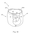
- Figure 1B illustrates a perspective view of an outside of the disposable wearable absorbent article 110 of the embodiment of Figure 1A , formed for wearing.
- the front portion of the first side panel 133 is connected to the back portion of the first side panel 137 via the first side interface 135 to form the first side panel 130.
- Figure 1C illustrates an enlarged view of a portion of the first side of the disposable wearable absorbent article 110 of the embodiment of Figure 1B .
- a connection 136 proximate to the first side interface 135 connects the front portion of the first side panel 133 with the back portion of the first side panel 137 to form the first side panel 130.
- the connection 136 can take various forms, such as a fastenable connection or a durable connection.
- the location of the connection 136 can vary in some embodiments. Alternatively, a side can be formed with more than one connection at various locations or without a distinct connection within the side.
- one or more parts of or at least a portion of the anchoring subsystem 170 can be structurally associated with the first side panel 130.
- at least a portion of an anchoring subsystem, or substantially all of an anchoring subsystem, or even all of an anchoring subsystem can be discrete from, or joined to, or attached to, or embedded in, or integral with a side panel.
- At least a portion of the SAM 150, or substantially all of the SAM 150, or even all of the SAM 150 is integral with the first side panel 130.
- the first side panel 130 has a first portion, which includes the integral portions of the anchoring subsystem 170, and a second portion outside of the first portion.
- first portion which includes the integral portions of the anchoring subsystem 170
- second portion outside of the first portion.
- the first portion would include the SAM pathway 151
- the second portion would include the area of the first side panel 130 that is longitudinally outboard from the SAM pathway 151 as well as the area of the first side panel 130 that is longitudinally inboard to the SAM pathway 151.
- this first portion and second portion can be configured in various ways, as described in the following examples.
- the disposable wearable absorbent article 110 can be configured such that substantially all of the first portion can be incrementally stretched to one or more lesser degrees and substantially all of the second portion can be incrementally stretched to one or more greater degrees.
- the disposable wearable absorbent article 110 can be configured such that the first portion can be incrementally stretched with a first particular number of teeth per a unit of distance, and the second portion can be incrementally stretched with a second particular number of teeth per the unit of distance, wherein the first particular number of teeth can be less than or equal to the second particular number of teeth.
- the first particular number of teeth can be at or about nine tenths, or four fifths, or three quarters, or two thirds, or one half, or one third, or one quarter, or one fifth, or one tenth of the second particular number of teeth.
- the disposable wearable absorbent article 110 can be configured such that substantially all of the first portion can be configured to have a higher directional modulus of elasticity, and substantially all of the second portion can be configured to have one or more lower directional modulii of elasticity, based on the directionality described in the modulus mapping method described herein.
- the higher directional modulus of elasticity can be at least 10, or at least 50, or at least 100, or at least 250, or at least 400 percent greater than the one or more lower directional modulii of elasticity.
- the disposable wearable absorbent article 110 can be configured such that substantially all of the first portion includes one or more higher caliper elastomers, and substantially all of the second portion includes one or more lower caliper elastomers.
- the disposable wearable absorbent article 110 can be configured such that substantially all of the first portion includes one or more higher performance elastomers, and substantially all of the second portion includes one or more lower performance elastomers.
- the disposable wearable absorbent article 110 can be configured such that one or more unstretched portions can be distributed throughout substantially all of the first portion, and substantially all of the second portion can be incrementally stretched.
- the disposable wearable absorbent article 110 can be configured such that one or more over-bonded portions can be distributed throughout substantially all of the first portion.
- the disposable wearable absorbent article 110 can be configured such that substantially all of the first portion can be configured to have one or more higher forces per unit width at a particular strain, and substantially all of the second portion can be configured to have one or more lower forces per unit width at the particular strain.
- the ratio of one of the higher force per unit width to one of the lower force per unit width can be at least 1.1, or at least 1.5, or at least 2, or at least 3.5, or at least 5.
- the disposable wearable absorbent article 110 can be configured such that one or more loads in the article can cause tension in the anchoring subsystem 170 before the load can cause tension in a portion of the first side panel that is outside of the anchoring subsystem 170. In various embodiments, the disposable wearable absorbent article 110 can be configured such that one or more loads in the article can cause greater tension in the anchoring subsystem 170 than in a portion of the first side panel that is outside of the anchoring subsystem 170.
- Figure 1C also shows tension lines 175.
- the tension lines 175 illustrate how the SAM 150 can balance collected loads with obtained holding forces, so that the anchoring subsystem 170 can at least assist in holding the disposable wearable absorbent article 110 in place on a wearer.
- the SAM 150 can collect loads at the front end 153, at the back end 159, and/or along the first SAM pathway 151.
- the SAM 150 can also obtain holding forces the front end 153, at the back end 159, and/or along the first SAM pathway 151 as the SAM 150 experiences anchoring from direct or indirect contact with a wearer's body underneath the first SAM pathway 151.
- the anchoring subsystem 170 is configured to indirectly anchor the absorbent core 125 to a wearer, in that, while the SAM 150 is not directly connected to the absorbent core 125, and the SAM pathway 151 is disposed outside of the absorbent core area 126, loads from the absorbent core 125 can be transmitted through various parts of the disposable wearable absorbent article 110 to the SAM 150, which can balance collected loads with obtained holding forces, so that the anchoring subsystem 170 can at least assist in holding the disposable wearable absorbent article 110 in place on a wearer.
- a pant-type disposable wearable absorbent article can also include a SAM configured in various other ways, as described in US non-provisional patent applications entitled “Disposable Wearable Absorbent Articles with Anchoring Subsystems” filed on the same date as the present application and further identified by attorney docket numbers 10897R, 10897R2, 10897R4, and 10897R5, each of which is incorporated by reference.
- Figure 2A illustrates a plan view of an inside of a front fastenable disposable wearable absorbent article 210, which includes an anchoring subsystem 270 with exactly one side anchoring member 250.
- a longitudinal centerline 213 and a lateral centerline 217 provide lines of reference for laterally inboard 212, laterally outboard 214, longitudinally inboard 216, and longitudinally outboard 218 relative locations.
- the disposable wearable absorbent article 210 includes a front 223 and a back 227.
- the disposable wearable absorbent article 210 also includes a chassis 220, a front waistband 221, a narrowest portion 222 of the chassis 220, an absorbent core 225 with longitudinal edges 224, an absorbent core area 226, a front waist edge 228-F, a back waist edge 228-B, and a back waistband 229.
- a portion of the chassis 220 is illustrated as cut away in order to show the absorbent core 225 and the longitudinal edges 224 more clearly.
- a front portion of a first side 281 is disposed in the front 223.
- a back portion of the first side 289 is disposed in the back 227.
- the disposable wearable absorbent article 210 has a first side ear 285 connected to the back portion of the first side 289.
- side ears are illustrated as distinct elements within disposable wearable absorbent articles. However, in various embodiments, one or more portions or all of a side ear may not be distinct elements within a disposable wearable absorbent article.
- the first side ear 285 includes a fastener 283 disposed proximate to a laterally distal edge of the first side ear 285.
- the first side ear 285 is configured to fasten to a fastening area 290 in the front 223.
- the disposable wearable absorbent article 210 includes the anchoring subsystem 270.
- the anchoring subsystem 270 is not directly connected to the absorbent core 225, and is outside of the absorbent core area 226, so the anchoring subsystem 270 is separate from the absorbent core 225.
- the anchoring subsystem 270 is considered a subsystem because the SAM 250 will not substantially or completely encircle the lower torso of a wearer when the disposable wearable absorbent article 210 is worn.
- the anchoring subsystem 270 is also considered a subsystem because the anchoring subsystem 270 is contained within a particular, defined portion of the disposable wearable absorbent article 210. In the embodiment of Figures 2A-2C , the anchoring subsystem 270 is contained within the first side of the disposable wearable absorbent article 210, so the anchoring subsystem 270 is considered a side anchoring subsystem.
- the anchoring subsystem 270 includes the SAM 250.
- the SAM 250 is considered a side anchoring member because at least a portion of the SAM 250 passes through a side of the disposable wearable absorbent article 210.
- the SAM 250 is contained within the first side ear 285.
- part or all of the SAM 250 can be configured as a geodesic, so that the anchoring subsystem 270 can provide geodesic anchoring.
- the SAM 250 is disposed along a SAM pathway 251.
- the SAM pathway 251 includes a front end 253, a back end 259, and a middle 255.
- the front end 253 is disposed at a front end location 252.
- the front end 253 can be considered disposed in the back 227, since the first side ear 285 is connected to the back portion of the first side 289.
- the front end 253 can be considered disposed in the front 223, since the first side ear 285 is fastened to the front portion of the first side 281.
- the back end 259 is disposed at a back end location 258.
- the middle 255 is disposed along the SAM pathway 251 at a middle location 256 between the front end 253 and the back end 259.
- the middle location 256 is illustrated as approximately halfway between the front end 253 and the back end 259.
- a middle location can be closer to the front end 253 or closer to the back end 259.
- the front end location 252 is located at a front end longitudinally outboard distance 262 from the lateral centerline 217.
- the back end location 258 is located at a back end longitudinally outboard distance 268 from the lateral centerline 217.
- the middle location is located at a middle longitudinally outboard distance 266 from the lateral centerline 217.
- the middle longitudinally outboard distance 266 is greater than the front end longitudinally outboard distance 262 and greater than the back end longitudinally outboard distance 268.
- the front end longitudinally outboard distance 262 is about equal to the back end longitudinally outboard distance 268.
- a front end longitudinally outboard distance can be nearly or exactly equal to a back end longitudinally outboard distance.
- a front end longitudinally outboard distance can be greater than a back end longitudinally outboard distance or a front end longitudinally outboard distance can be less than a back end longitudinally outboard distance.
- a portion of the SAM pathway 251 between the middle 255 and the front end 253 turns longitudinally inboard as it nears the front end 253, and a portion of the SAM pathway 251 between the middle 255 and the back end 259 turns longitudinally inboard as it nears the back end 259.
- the front end location 252 is proximate to the fastener 283.
- the front end location 252, when the article 210 is formed for wearing, is described in connection with Figure 2C .
- the back end location 258 is outside of the absorbent core area 226, in the back portion of the first side 289, laterally outboard from the longitudinal edge 224 of the absorbent core 225, laterally outboard from the narrowest portion 222 of the chassis 220, within the first side ear 285, proximate to a laterally inboard edge of the first side ear 285.
- a back end location can be outside of the first side ear 285, and/or laterally inboard to the narrowest portion 222 of the chassis 220, and/or laterally inboard to the longitudinal edges 224 of the absorbent core 225, and/or outside of the back portion of the first side 289, and/or inside of the absorbent core area 226.
- the disposable wearable absorbent article 210 also includes a second side with a front portion of the second side 291 disposed in the front 223 and a back portion of the second side 299 disposed in the back 227.
- the disposable wearable absorbent article 210 has a second side ear 295, configured to fasten to the fastening area 290.
- the second side ear 295 is configured similar to the first side ear 285.
- a second side ear can, alternatively, be configured differently.
- the disposable wearable absorbent article 210 can also include an outer cover, which can, in various embodiments, be separate from the anchoring subsystem 270. In some embodiments, part or all of such an outer cover can be stretchable, elastic, or extensible.
- Figure 2B illustrates a perspective view of an outside of the disposable wearable absorbent article 210 of the embodiment of Figure 2A , formed for wearing.
- the fastener 283 is fastened to the fastening area 290.
- Figure 2C illustrates an enlarged view of a portion of the first side of the disposable wearable absorbent article 210 of the embodiment of Figure 2B .
- the fastener 283 is fastened to the fastening area 290, so that the first side ear 285 fastens the back 227 to the front 223.
- a portion of the first side ear 285 is disposed in the front 223 and a portion of the first side ear 285 is disposed in the back 227.
- the front end location 252 is outside of the absorbent core area 226, in the front portion of the first side 281, laterally outboard from the longitudinal edge 224 of the absorbent core 225, and laterally outboard from the narrowest portion 222 of the chassis 220.
- a front end location can be laterally inboard to the narrowest portion 222 of the chassis 220, and/or laterally inboard to the longitudinal edge 224 of the absorbent core 225, and/or outside of the front portion of the first side 281.
- the front end location 252 and the back end location 258 are both outside of the absorbent core area 226.
- a front end location when an article is formed for wearing, a front end location can be disposed inside of the absorbent core area while a back end location can be disposed outside of the absorbent core area.
- a front end location when an article is formed for wearing, a front end location can be disposed outside of the absorbent core area while a back end location can be disposed inside of the absorbent core area.
- one or more parts of or at least a portion of the anchoring subsystem 270 can be structurally associated with the first side ear 285.
- at least a portion of an anchoring subsystem, or substantially all of an anchoring subsystem, or even all of an anchoring subsystem can be discrete from, or joined to, or attached to, or embedded in, or integral with a side ear.
- at least a portion of the SAM 250, or substantially all of the SAM 250, or even all of the SAM 250 can be discrete from, or joined to, or attached to, or embedded in, or integral with the first side ear 285.
- the first side ear 285 can be considered to have a first portion, which includes the integral portions of the anchoring subsystem 270, and a second portion outside of the first portion.
- the first portion would include the SAM pathway 251
- the second portion would include the area of the first side ear 285 that is longitudinally outboard from the SAM pathway 251 as well as the area of the first side ear 285 that is longitudinally inboard to the SAM pathway 251.
- this first portion and second portion can be configured in various ways, as described in connection with the embodiment of Figure 1C .
- the disposable wearable absorbent article 210 can be configured such that one or more loads in the article can cause tension in the anchoring subsystem 270 before the load can cause tension in a portion of the first side ear that is outside of the anchoring subsystem 270. In various embodiments, the disposable wearable absorbent article 210 can be configured such that one or more loads in the article can cause greater tension in the anchoring subsystem 270 than in a portion of the first side ear that is outside of the anchoring subsystem 170.
- Figure 2C also shows tension lines 275.
- the tension lines 275 illustrate how the SAM 150 can balance collected loads with obtained holding forces, so that the anchoring subsystem 270 can at least assist in holding the disposable wearable absorbent article 210 in place on a wearer.
- the SAM 250 can collect loads at the front end 253, at the back end 259, and/or along the first SAM pathway 251.
- the SAM 250 can also obtain holding forces the front end 253, at the back end 259, and/or along the first SAM pathway 251 as the SAM 250 experiences anchoring from direct or indirect contact with a wearer's body underneath the first SAM pathway 251.
- the anchoring subsystem 270 is configured to indirectly anchor the absorbent core 225 to a wearer, in that, while the SAM 250 is not directly connected to the absorbent core 225, and the SAM pathway 251 is disposed outside of the absorbent core area 226, loads from the absorbent core 225 can be transmitted through various parts of the disposable wearable absorbent article 210 to the SAM 250, which can balance collected loads with obtained holding forces, so that the anchoring subsystem 270 can at least assist in holding the disposable wearable absorbent article 210 in place on a wearer. As a result, the disposable wearable absorbent article 210 can feel comfortable, look attractive, and perform well as the article tends to stay in place on a wearer and not leak.
- Figure 2D illustrates an enlarged view of a portion of a front fastenable disposable wearable absorbent article 210-2 including a first side ear 285-2 with an active fastener 286 and a passive fastener 287 as well as an anchoring subsystem 270 having exactly one side anchoring member 250-2.
- the disposable wearable absorbent article 210-2 is configured as the disposable wearable absorbent article 210 of the embodiments of Figures 2A-2C , except as described below.
- the first side ear 285-2 is configured as the first side ear 285, except that instead of fastener 283 the first side ear 285-2 includes the active fastener 286 and the passive fastener 287.
- the active fastener 286 is disposed proximate to a laterally distal edge of the first side ear 285-2 and the passive fastener 287 is disposed proximate to a longitudinally inboard edge of the first side ear 285-2.
- an active fastener and a passive fastener can be disposed in other locations.
- the active fastener 286 is fastened to the fastening area 290 and the passive fastener 287 is fastened to a passive fastening location on the front portion of the first side 281, so that the first side ear 285-2 fastens the back 227 to the front 223.
- the SAM 250-2 is configured as the SAM 250, except that the front end 252 of the SAM pathway 251 is disposed at the front end location 253, which is proximate to the passive fastener 287.
- the SAM 250 can collect loads at the front end location 253 through various parts of the disposable wearable absorbent article 210, such as through the passive fastener 287.
- the second side ear 295 (not shown) can be configured similar to the first side ear 285-2 or can be configured differently.
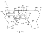
- Figure 2E illustrates an enlarged view of a portion of a front fastenable disposable wearable absorbent article 210-3 including a first side ear 285-3 with a first active fastener 282 and a second active fastener 284 as well as an anchoring subsystem 270 having exactly one side anchoring member 250-3.
- the disposable wearable absorbent article 210-3 is configured as the disposable wearable absorbent article 210 of the embodiments of Figures 2A-2C , except as described below.
- the front portion of the first side 281 includes a first fastening area 290-1 and a second fastening area 290-2.
- the second fastening area is disposed longitudinally inboard to the first fastening area 290-1.
- a front portion of a first side could include a single fastening area of a size similar to the first fastening area 290-1 and the second fastening area 290-2 combined.
- the first side ear 285-3 is configured as the first side ear 285, except that instead of fastener 283, the first side ear 285-3 includes the first active fastener 282 and the second active fastener 284.
- the first active fastener 282 is disposed proximate to a laterally distal edge of the first side ear 285-3.
- the second active fastener is disposed proximate to the laterally distal edge of the first side ear 285-3 and longitudinally inboard to the first active fastener 282.
- the first active fastener 282 is fastened to the first fastening area 290-1 and the second active fastener 284 is fastened to the second fastening area 290-2, so that the first side ear 285-3 fastens the back 227 to the front 223.
- the SAM 250-3 is configured as the SAM 250, except that the front end 252 of the SAM pathway 251 is disposed at the front end location 253, which is proximate to the second active fastener 284.
- the SAM 250 can collect loads at the front end location 253 through various parts of the disposable wearable absorbent article 210, such as through the second active fastener 284.
- the second side ear 295 (not shown) can be configured similar to the first side ear 285-3 or can be configured differently.
- a front fastenable disposable wearable absorbent article can also include a SAM configured in various other ways, as described in US non-provisional patent applications entitled “Disposable Wearable Absorbent Articles with Anchoring Subsystems” filed on the same date as the present application and further identified by attorney docket numbers 10897R, 10897R2, 10897R4, and 10897R5, each of which is incorporated by reference.
- the presence of one or more anchoring subsystem elements can be detected by using a modulus mapping method.
- This method can also be used to measure particular modulus of elasticity values for one or more anchoring subsystem elements, such as a SAM.
- the modulus mapping method is described below, and in connection with the embodiments of Figures 3A-3E .
- a first step in the modulus mapping method is to determine an area of interest in a disposable wearable absorbent article.
- the area of interest is a continuous portion of the article, which completely contains the one or more anchoring subsystem elements to be tested.
- the area of interest also includes one or more portions of the article surrounding the anchoring subsystem element(s).
- the area of interest is not limited to the anchoring subsystem elements, but includes the one or more portions of the article that form the physical context on all sides of each of the element(s).
- the area of interest should contain enough of this physical context to be tested with the modulus mapping method on all sides of each of the anchoring system element(s). In this way, the presence of each of the anchoring subsystem element(s) can be detected within their physical context, in the area of interest.
- an anchoring subsystem element may be known from knowledge of the article.
- a side panel 330 of a pant-type disposable wearable absorbent article is known to contain an anchoring subsystem with a SAM.
- the side panel 330 is the area of interest.
- the presence of an anchoring subsystem element may be apparent upon visual inspection of the article or may be suspected based on other facts.
- the area of interest can be determined by testing various portions of one or more samples of a disposable wearable absorbent article with the steps of the modulus mapping method, as will be understood by one of ordinary skill in the art.
- a second step in the modulus mapping method is to cut the area of interest from the disposable wearable absorbent article. If the area of interest is a side panel of a disposable wearable absorbent article, then continuous cuts are made through the article along one or more paths between the side panel and the rest of the article. Any connections in the side panel are left fastened and/or intact, so the area of interest can be a continuous portion of the article.
- the area of interest is a side ear of a front fastenable disposable wearable absorbent article
- continuous cuts are made through the article along one or more paths between the side ear and the rest of the article. If the side ear is fastened, then it is unfastened, for complete removal from the article.
- continuous cuts are made through the article, on both sides of the area, from points on a waist edge of the article, cutting on paths perpendicular to the waist edge. These cuts either continue until they reach a leg opening of the article, or turn to reach the leg opening on the shortest cutting path parallel to the waist edge. Any connections in the area of interest are left fastened and/or intact, so the area of interest can be a continuous portion of the article.
- a third step in the modulus mapping method is to mark the area of interest with a map, which is a grid of squares. While the area of interest is marked, the area is laid out flat, so the surface of the area of interest is not disturbed or distorted.
- the gridlines of the map should run parallel to and perpendicular to the lateral direction of the disposable wearable absorbent article. However, if the material of the area of interest has a primary direction of elasticity, stretchability, or extensibility, then the gridlines of the map should run parallel to and perpendicular to that primary direction of stretch.
- Each of the squares in the grid is 5.0 millimeters by 5.0 millimeters.
- the gridlines can be measured in various ways, such as by using a calibrated ruler.
- the gridlines can also be marked in various ways, such as by using a fine tipped marking pen.
- the marked map is a grid of squares with rows R1 through Rn and columns C1 through Cn. Thus, each square on the map can be uniquely referenced by row and column number (e.g. C1:R1 for the square of column 1, row 1).
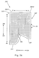
- Figure 3A illustrates an enlarged view of a portion of the side panel 330 of the disposable wearable absorbent article, cut from the article and marked with a map 371, for testing with the modulus mapping method.
- Figure 3A illustrates directions of laterally inboard 312 and laterally outboard 314 (using the lateral directions for a back 327 of the article for ease of reference) as well as directions for longitudinally inboard 316 and longitudinally outboard 318.
- the portion of the side panel 330 includes a portion of the back 323, a portion of the front 327, a front waist edge 328-F, a back waist edge 328-B, a front portion of the side panel 333, a connection 336, and a back portion of the side panel 337.
- the material of the area of interest has a primary direction of stretchability in the lateral direction. Therefore, the map 371 is marked on the side panel 330, as described above, so that the gridlines of the map 371 run parallel to and perpendicular to that primary direction of stretch, which is the lateral direction.
- a fourth step in the modulus mapping method is to test the area of interest.
- the dimensions of the area of interest are measured and recorded, for use in calculating modulus of elasticity.
- a 3.14 cm2 round foot caliper is used, with 0.5 kPa of pressure and 10 seconds of residence time.
- the testing uses a constant rate of extension tensile tester, fitted with a 5 N load cell.
- the tensile tester includes a computer interface, such as a MTS Alliance with TestWorks 4 software (available from MTS Systems Corp., Eden Prairie, Minnesota). With regard to the test equipment described below, dimensions are given as precise values.
- the tensile tester is fitted with a set of 10 N AdvantageTM pneumatic grips (available from MTS as part 100-032-017) and 15 millimeter wide by 8 millimeter high 10 N AdvantageTM grip faces with smooth steel surface (available from MTS as part 56-163-702).
- Each of the grip faces is modified by mounting a hard rubber facing on the grip face.
- the rubber facing is a hard neoprene rubber with a Durometer rating of 70A.
- the rubber facing is 5.00 millimeters wide by 8.0 millimeters high by 2.0 millimeters deep.
- the rubber facing is centered on the base width of the grip face.
- Figure 3C illustrates a modified pneumatic grip 301, as described above, for use in the modulus mapping method.
- the modified pneumatic grip 301 includes base grip width 302 (15 millimeters) and base grip height 303 (8 millimeters).
- the modified pneumatic grip 301 also includes a hard rubber facing 305 with a facing width 306 (5.00 millimeters), a facing height 307 (8.0 millimeters), and a facing depth 308 (2.0 millimeters).
- the area of interest is tested with the modulus mapping method as follows.
- references to the area of interest refer to the side panel 330 of the embodiment of Figure 3A .
- the data acquisition rate of the tensile tester is set to 100 Hz and the gage length is set to 5.0 mm.
- the crosshead and the load cell are zeroed. If there is no primary direction of elasticity, stretchability, or extensibility in the area of interest, then the area of interest is inserted and aligned as described below.
- the area of interest is inserted into the upper pneumatic grip at the square C1:R1 and oriented to pull the side panel 330 in the lateral direction of the disposable wearable absorbent article.
- the upper grip is aligned outside of square C1:R1, along the laterally outboard gridline of the square C1:R1, and closed.
- the area of interest is also inserted into the lower pneumatic grip, aligned outside of square C1:R1, along the laterally inboard gridline of the square, and closed.
- the area of interest is inserted and aligned as described below.
- the area of interest is inserted into the upper pneumatic grip at the square C1:R1 and oriented to pull the side panel 330 in the primary direction of stretch.
- the upper grip is aligned outside of square C1:R1, along a first gridline of the square that is perpendicular to the primary direction of stretch, and closed.
- the area of interest is also inserted into the lower pneumatic grip, aligned outside of square C1:R1, along a second gridline of the square that is opposite from the first gridline and also perpendicular to the primary direction of stretch, and closed.
- the area of interest should be under enough tension to eliminate any slack, but with less than 0.02 N of force on the load cell.
- the tensile tester is started and data is collected. The grips are moved apart at a constant rate of 25 millimeters per minute to 10% strain.
- the modulus of elasticity of the square is calculated as a directional modulus of elasticity, since the area of interest is pulled in a particular direction, e.g. the lateral direction or the primary direction of stretch.
- the directional modulus of elasticity of the square is calculated as the slope of the linear region of the resulting stress versus strain curve, using a slope segment length of 50% to determine the modulus line.
- Figure 3C illustrates an exemplary graph of the modulus of elasticity of a square of the map 371, with stress 372 in mega Pascals versus strain 373 as a percentage, and a modulus line 377 using a slope segment length of 50% from point 378 to point 379.
- the directional modulus of elasticity is determined to ⁇ 0.01 mega Pascals and recorded. This testing procedure is repeated for each square on the map, testing the first column (from C1:R1 to C1:Rn) followed by each successive column (from C2 to Cn).
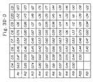
- Figure 3D illustrates an exemplary chart with directional modulus of elasticity values in mega Pascals, obtained from the modulus mapping method testing and recorded for each square of the map 371 of the area of interest, which is the side panel 330 of the disposable wearable absorbent article.
- a fifth step in the modulus mapping method is to plot and evaluate the directional modulus of elasticity values obtained from the modulus mapping method testing.
- the directional modulus of elasticity values are transferred to a spreadsheet such as Microsoft ExcelTM and plotted as a surface contour plot.
- a maximum Z-axis value to truncate high modulus values resulting from seams, chassis bonds, and/or other such structural discontinuities in the area of interest that are unrelated to anchoring subsystem element(s).
- a maximum value of approximately three and a half times the upper value of the directional modulus of elasticity in the lowest modulus region is useful for the directional modulus of elasticity values in the embodiment of Figure 3D .
- intervals to visually evaluate the plot for existing patterns of high and low directional modulii of elasticity in the area of interest. A minimum of five intervals should be used for this evaluation. For example, an interval value of approximately 0.29 mega Pascals is useful for the directional modulus of elasticity values in the embodiment of Figure 3D .
- One skilled in the art of visual pattern recognition will understand that these values are representative and can be determined empirically for a given set of directional modulus of elasticity values.
- Figure 3E illustrates an exemplary surface contour plot of the directional modulus of elasticity values of the chart of the embodiment of Figure 3D , as described above, for use in the modulus mapping method.
- the maximum Z-axis values are truncated at 1.39 mega Pascals, which is three and half times the upper value of the directional modulus of elasticity in the lowest modulus region (e.g. 0.39 mega Pascals).
- the major value intervals are chosen to be 0.29 mega Pascals.
- the plot of Figure 3E illustrates the presence of an anchoring subsystem with exactly one SAM 350.
- the size and/or shape of the SAM 350 in the example embodiment of Figures 3A-3E may or may not correspond with other embodiments of the present disclosure.
- the modulus mapping method can be used to detect the presence of embodiments of SAMs of the present disclosure, as will be understood by one of ordinary skill in the art.
- the plot of Figure 3E indicates that the SAM has a directional modulus of elasticity between 0.58 and 0.77 mega Pascals.
- the one SAM 350 extends through a side connection in the side panel.
- the modulus mapping method can be used to detect the presence of one or more anchoring subsystem elements and to measure particular directional modulus of elasticity values for such elements.
- Embodiments of the present disclosure include disposable wearable absorbent articles with anchoring subsystems that fit wearers well.
- the designs of these articles help prevent the articles from sagging or slipping down on a wearer.
- the disposable wearable absorbent articles of the present disclosure can feel comfortable, look attractive, and perform well as the articles tend to stay in place on wearers and not leak.
Description
- In general, embodiments of the present disclosure relate to wearable absorbent articles. In particular, embodiments of the present disclosure relate to disposable wearable absorbent articles with anchoring subsystems.
- Disposable wearable absorbent articles include disposable diapers and disposable incontinence undergarments. A disposable wearable absorbent article can receive and contain bodily waste while being worn by a wearer. Such articles can be made with various materials in a number of configurations. The design of a disposable wearable absorbent article can affect the way that the article fits on a wearer. Unfortunately, some disposable wearable absorbent articles fit wearers poorly. As an example, some disposable wearable absorbent articles can sag or slip down on a wearer. A disposable wearable absorbent article that sags or slips down on a wearer can feel uncomfortable, look unattractive, and perform poorly as the article tends to leak.
-
U.S. Patent 5,873,870 refers to absorbent articles designed to provide sustained dynamic fit about the wearer during use as well as to improve the containment of body exudates and wearer comfort / mobility. A closure system is designed so that a plane of tension is formed at least about the front waist portion of the article to preclude rollover of the front waist portion. -
WO 2007/15217 A1 -
U.S. Patent 5,899,895 refers to absorbent articles having extensibe side panel features that improve the dynamic fit of the diaper around the legs and waist of the wearer. A waist panel and a thigh panel are operatively associated so that the waist panel has a primary direction of extensibility and the thigh panel has a primary direction of extensibility in a different direction. -
U.S. Patent 5,846,232 is about absorbent articles including extensible zones. The extensible zones typically include an elastic layer between and mounted to extend with the outer cover layer and the bodyside liner layer. -
U.S. Patent 6,572,598 discloses a disposable garment having enhanced extensibility around the leg openings. The disposable garment comprises a chassis and seams. The chassis includes an ear panel that is rendered extensible to form an extensible ear. -
-
Figure 1A illustrates a plan view of an inside of a pant-type disposable wearable absorbent article including a side panel with an anchoring subsystem having exactly one side anchoring member, according to embodiments of the present disclosure. -
Figure 1B illustrates a perspective view of an outside of the disposable wearable absorbent article of the embodiment ofFigure 1A , formed for wearing. -
Figure 1C illustrates an enlarged view of a portion of a side of the disposable wearable absorbent article of the embodiment ofFigure 1B . -
Figure 2A illustrates a plan view of an inside of a front fastenable disposable wearable absorbent article including a side ear with one fastener as well as an anchoring subsystem having exactly one side anchoring member, according to embodiments of the present disclosure. -
Figure 2B illustrates a perspective view of an outside of the disposable wearable absorbent article of the embodiment ofFigure 2A , formed for wearing. -
Figure 2C illustrates an enlarged view of a portion of a side of the disposable wearable absorbent article of the embodiment ofFigure 2B . -
Figure 2D illustrates an enlarged view of a portion of a front fastenable disposable wearable absorbent article including a side ear with an active fastener and a passive fastener as well as an anchoring subsystem having exactly one side anchoring member, according to embodiments of the present disclosure. -
Figure 2E illustrates an enlarged view of a portion of a front fastenable disposable wearable absorbent article including a side ear with two active fasteners as well as an anchoring subsystem having exactly one side anchoring member, according to embodiments of the present disclosure. -
Figure 3A illustrates an enlarged view of a side panel of a disposable wearable absorbent article, cut from the article and marked with a map for testing with a modulus mapping method, according to embodiments of the present disclosure. -
Figure 3B illustrates a modified pneumatic grip, for use in the modulus mapping method according to embodiments of the present disclosure. -
Figure 3C illustrates an exemplary graph of the modulus of elasticity of a square of the map of the embodiment ofFigure 3A , according to embodiments of the present disclosure. -
Figure 3D illustrates an exemplary chart with modulus of elasticity values, obtained from the modulus mapping method testing and recorded for each square of the map of the embodiment ofFigure 3A , according to embodiments of the present disclosure. -
Figure 3E illustrates an exemplary surface contour plot of the modulus of elasticity values of the chart of the embodiment ofFigure 3D , according to embodiments of the present disclosure. - Embodiments of the present disclosure include disposable wearable absorbent articles with anchoring subsystems that fit wearers well. The designs of these articles help prevent the articles from sagging or slipping down on a wearer. As a result, the disposable wearable absorbent articles of the present disclosure can feel comfortable, look attractive, and perform well as the articles tend to stay in place on wearers and not leak.
- Embodiments of the present disclosure include disposable wearable absorbent articles. Throughout the present disclosure, the term "disposable wearable absorbent article" refers to an article, configured to be worn on a lower torso of a human body of a wearer, configured to receive and contain bodily exudates (e.g., urine and feces) from the body, and configured to be partly or wholly disposed of after a single use by the wearer. Thus, a disposable wearable absorbent article is configured such that the soiled article, or a soiled portion of the article, is not intended to be restored and reused (e.g., not intended to be laundered). Examples of disposable wearable absorbent articles include disposable diapers, disposable incontinence undergarments, etc. A disposable wearable absorbent article can be configured in various ways, such as a pant-type configuration or a front fastenable configuration.
- In embodiments of the present disclosure, a disposable wearable absorbent article includes an absorbent core. Throughout the present disclosure, the term "absorbent core" refers to a part of a disposable wearable absorbent article configured to absorb bodily exudates received into the article from a body of a wearer. An absorbent core can be configured in various ways, as will be understood by one of ordinary skill in the art. Examples of absorbent cores include absorbent core assemblies (with one or more optional core structures), bucket-shaped absorbent cores, removable and/or replaceable absorbent cores, etc.
- When a disposable wearable absorbent article is placed on a wearer, the article is placed in an initial position with respect to the wearer. The location of this initial position can depend on a number of factors, such as the size of the article, the shape of the wearer's body, and the manner in which the article is placed on the wearer. For example, an initial position of a fastenable diaper can depend in part on a location at which the diaper is fastened around a wearer. However, as a disposable wearable absorbent article is worn by a wearer, a number of forces can act upon the article.
- Some of these forces can tend to move the article on the wearer. Throughout the present disclosure, the term "load" refers to a force that tends to move a disposable wearable absorbent article out of place on a wearer. First, a disposable wearable absorbent article can experience various loads from placement of the article on a wearer. As an example, some pretension forces from fastening the article can drive the article downward. Second, a disposable wearable absorbent article can experience various loads from the article's environment. A wearer's clothes can pull on the article, for example. Third, a disposable wearable absorbent article can experience various loads from a wearer's movements. For example, as a wearer changes positions or moves about, the wearer's body can push against parts of the article or create dynamic forces in the article. Fourth, the force of gravity can move a disposable wearable absorbent article down on a wearer. The article can experience a significant load from the force of gravity, due to a mass of the article as well as a mass of any bodily waste contained by the article. These loads, can act upon a disposable wearable absorbent article, tending to move the article on a wearer.
- However, other forces acting upon a disposable wearable absorbent article can tend to hold the article in place on a wearer. First, a disposable wearable absorbent article can experience various holding forces from placement of the article on a wearer. As an example, other pretension forces from fastening the article can drive the article upward. Second, parts of a disposable wearable absorbent article can experience friction forces from contact with a wearer's skin. For example, the article can experience a friction force where a waistband of the article wraps around and against the wearer's waist. Third, parts of a disposable wearable absorbent article can experience reaction forces from contact with various external anatomical features on a wearer's body. As an example, the article can experience reaction forces where the article contacts protruding portions of the wearer's hips. In this example, the reaction forces react against the force of gravity by pushing up on the article. These holding forces can act upon a disposable wearable absorbent article, tending to hold the article in place on a wearer.
- As some forces tend to move a disposable wearable absorbent article down on a wearer and other forces tend to hold the article up on the wearer, part or all of the article may or may not move, depending on whether or not such forces are balanced. If the forces tending to hold the article up can equal the forces tending to move the article down, then the article can hold in place on the wearer. If the forces tending to move the article down are greater than the forces tending to hold the article up, then part or all of the article can move out of place and down on the wearer. Sometimes, forces can move down part or all of disposable wearable absorbent article, resulting in sagging and/or slipping.
- However, embodiments of the present disclosure can help prevent disposable wearable absorbent articles from sagging and/or slipping down on a wearer. A disposable wearable absorbent article can include an anchoring subsystem. In various embodiments, an anchoring subsystem can be configured to collect at least some of the loads acting upon the article. The anchoring subsystem can also be configured to anchor itself to a body of a wearer. In this way, the anchoring subsystem can balance at least some of the collected loads with holding forces obtained from the anchoring. By balancing the collected loads with the obtained holding forces, the anchoring subsystem can at least assist in holding the disposable wearable absorbent article in place on a wearer.
- An anchoring subsystem can be configured to collect loads acting upon a disposable wearable absorbent article, to anchor itself to a body of a wearer, and to balance the collected loads with holding forces obtained from the anchoring. Throughout the present disclosure, the term "anchored" refers to a configured relationship between part or all of an anchoring subsystem in a disposable wearable absorbent article and part or all of a body of a wearer, while the article is worn by the wearer. Where an element of an anchoring subsystem is anchored to a portion of a body of a wearer, at least part of the element is in direct and/or indirect contact with the portion of the body and the anchoring subsystem is configured to at least reduce and/or prevent relative movement between the element and the portion, while the article is worn by the wearer.
- An anchoring subsystem can be anchored to a body of a wearer with one or more elements of the anchoring subsystem configured to contact various parts of a body of a wearer. For example, an anchoring subsystem can be at least partially anchored by wrapping one or more anchoring subsystem elements at least partway around a front, back, and/or side of a body of a wearer, thus creating friction and/or reaction forces.
- A part of the body with a relatively smaller radius of curvature can, in some embodiments, provide greater friction forces, since an element can tend to wrap around such parts more tightly. This is due to the physics of a flexible material that is wrapped around a curved surface and placed under tension. In this scenario, as a tensile force places the flexible material under tension, the flexible material exerts a normal force perpendicular to and inward on the curved surface. According to the basic Capstan formula, the normal force is proportional to the tensile force divided by the radius of the curved surface. Thus, at a given tensile force as the radius becomes smaller the normal force becomes larger.
- Also as an example, an anchoring subsystem can be at least partially anchored by setting one or more anchoring subsystem elements on, around, and/or above protruding portions of a body of a wearer, thus creating friction and/or reaction forces. A part of the body with a relatively larger horizontal protrusion can, in some embodiments, provide greater reaction forces, since an element can tend to hang and/or ride on such parts more securely.
- In order to collect loads, anchor itself to a body of a wearer, and balance various forces, an anchoring subsystem can be configured to include one or more anchoring subsystem elements. In some embodiments, an anchoring subsystem element can be an elongated element configured to carry tension. Anchoring subsystem elements can follow various pathways on external surfaces of a body of a wearer of the disposable wearable absorbent article in which the anchoring subsystem is included. The shapes of these external surfaces can affect the shapes of the pathways. The shapes of the pathways can, in turn, affect configurations of anchoring subsystem elements.
- Many external surfaces on human bodies include curved shapes, such as a curve around a hip of a human body. Different human bodies can include different curves as bodies have various sizes and shapes. In some embodiments, part or all of an anchoring subsystem element that follows a curved pathway can be a geodesic.
- The term geodesic relates to a theoretical element with mathematical properties described by curved geometries. In this theoretical context, a geodesic is a curved line on a curved surface, wherein the curved line appears to travel straight, without turning to the left or to the right, when viewed from that curved surface. In other words, a geodesic can be thought of as a line pulled taut on a frictionless curved surface. On a flat surface, the shortest distance between two points is a straight line. On a curved surface, the shortest distance between two points is a geodesic. More information on geodesics and their mathematical properties can be found in texts on differential geometry and the theory of general relativity, for example Barrett O'Neill, Elementary Differential Geometry Ch. 7 (Academic Press 2006); and James Foster & David J. Nightingale, A Short Course in General Relativity Ch. 2.1 (Springer Science and Business Media 2006).
- Part or all of an anchoring subsystem element can be configured as a geodesic. While, throughout the present disclosure, anchoring subsystem elements are described as geodesics, these descriptions are intended to mean that such anchoring subsystem elements are configured as close approximations to theoretical geodesic elements. Real world elements cannot behave exactly like theoretical geodesic elements since real world elements always have at least some thickness, always experience at least some friction, and are always subject to at least some small non-axial outside forces, as will be understood by one of ordinary skill in the art.
- Part or all of an anchoring subsystem element can be configured as a geodesic as the element follows various convex curved pathways on external surfaces of a body of a wearer. An anchoring subsystem element that is loaded in tension (e.g., axial loading) can be configured as a geodesic, since the tension can conform the element to the convex curved pathway. When a point load is added to an anchoring subsystem element that is a geodesic, at an angle other than in-line with the geodesic, that point load deforms the original geodesic, dividing the original geodesic into two new geodesics in the anchoring subsystem element.
- Similarly, when an anchoring subsystem element, configured in tension as a geodesic, passes over a concave portion of a generally convex external surface of a human body, the element bridges the concave portion, separating the anchoring subsystem element into two geodesics on either convex side of the concave portion. Further, the bridging portion of the anchoring subsystem element is also a geodesic, since it is a straight line in space.
- When an anchoring subsystem element that is a geodesic is subjected to a load distributed along at least a portion of the length of the element, at an angle other than in-line with the geodesic, the element no longer behaves as a geodesic, and instead begins to act in a manner referred to herein as "geometric anchoring." An anchoring subsystem can include one or more anchoring subsystem elements, at least some of which can be configured as geodesics.
- One kind of anchoring subsystem element is a side anchoring member (SAM). A SAM is one or more physical, tension-carrying elements and/or areas disposed along a defined SAM pathway in an anchoring subsystem of a disposable wearable absorbent article. A SAM has two defined ends, a middle between the two ends, and a defined length from its one end to its other end. A SAM can have one or more widths, each of which is less than its defined length. A SAM also has a centerline, running along the SAM pathway, in the center of its width, from its one end to its other end. A SAM pathway cannot substantially or completely encircle the lower torso of the body of the wearer. At least a portion of a SAM pathway passes through a side of the disposable wearable absorbent article. In some embodiments, a SAM can be contained within a side of the disposable wearable absorbent article. Further, in various embodiments, a SAM can be contained within a side panel or a side ear of a disposable wearable absorbent article.
- A side of a disposable wearable absorbent article can be defined in various ways. A side of a disposable wearable absorbent article can include a portion of a front of the article as well as a portion of a back of the article. Sometimes, a side of a disposable wearable absorbent article can be considered disposed in a portion of the article that is laterally offset from a longitudinal centerline of the article. Throughout the present disclosure, unless otherwise stated, a side of a disposable wearable absorbent article is disposed in a portion of the article that is laterally outboard from longitudinal edges of an absorbent core of the article. In some instances, a side of a disposable wearable absorbent article can be considered disposed in a portion of the article that is laterally outboard from a narrowest portion of a chassis of the article. In various instances, a side of a disposable wearable absorbent article can be considered disposed in a side panel or a side ear of the article. Embodiments of the present disclosure can be used with any of these definitions of a side of a disposable wearable absorbent article.
- In an anchoring subsystem of a disposable wearable absorbent article, one or more SAMs can be configured to contact various parts of a body of a wearer, to at least assist in anchoring the anchoring subsystem to the body. A SAM can receive at least some collected loads from one or more elements of the disposable wearable absorbent article, such as a chassis, a fastener, a leg cuff, etc. A SAM can also provide holding forces to help balance the collected loads through contact with the body. In balancing these loads and forces, the SAM carries tensions in the anchoring system. This balancing can enable the anchoring subsystem to at least assist in holding a disposable wearable absorbent article in place on a wearer.
- A SAM can be configured in various forms. In some embodiments, a SAM can include a number of elements, such as fasteners. Part or all of a SAM can be straight, curved, angled, segmented, or other shapes, or combinations of any of these shapes. A SAM pathway can be a unitary, continuous pathway, or can be formed by a number of discrete elements and/or separate areas disposed along a SAM pathway. As examples, a SAM can be formed by substantially parallel strands of material running through a side panel or a side ear, or by a series of pieces of material attached to a side panel or a side ear, or by a distribution of unstretched areas in an incrementally stretched side panel or side ear.
- Part or all of a SAM can be structurally associated with one or more elements of the disposable wearable absorbent article. As examples, part or all of a SAM can be discrete from and/or joined to and/or attached to and/or embedded in and/or integral with one or more elements of the disposable wearable absorbent article. Throughout the present disclosure, the term "joined" refers to configurations whereby an element is directly connected to another element by affixing the element directly to the other element and to configurations whereby an element is indirectly secured to another element by affixing the element to intermediate member(s) which in turn are affixed to the other element.
- A SAM can be made from any material suitable for carrying tensions in an anchoring system. Part or all of a SAM can include one or more of various elastic, inelastic, extensible, inextensible, stretchable, and/or non-stretchable material(s) and/or any other suitable material(s) and/or combinations of any of these materials. As examples, part or all of a SAM can include one or more of various elastomeric materials, such as extruded films, elastics, nonwovens, scrims, slot-coated films, sprayed or melt-blown fibers, and/or printed elastics and/or any other suitable elastomeric material(s) and/or combinations of any of these materials.
- Also as examples, part or all of a SAM can be structurally associated with part or all of one or more elements of a disposable wearable absorbent article, such as embodiments wherein one or more of the element(s) are configured with an elastic nonwoven, with an elastic film and extensible nonwoven, with an extensible film and an elastic nonwoven, to be pre-stretched with elastic strands allowed to contract, to be incrementally stretched, with zero strain laminate, and/or in combinations of these and/or other configurations. In some embodiments, a SAM can include one or more laminate materials. In various embodiments, a SAM can be formed from various basis weights, chemistries, and/or incremental stretchings, as will be understood by one of ordinary skill in the art.
- A SAM can be any suitable width or thickness. For example, a SAM can be from 5 mm to about 50 mm wide or any width within that range. The width and/or thickness of a SAM can be substantially or completely uniform over one or more parts of the SAM or over the entire length of the SAM, or can vary over the length of the SAM. In some embodiments, a SAM can have a substantially uniform width of about 10 mm, about 20 mm, or about 30 mm. Throughout the present disclosure, unless otherwise stated, the width of a SAM is measured at a particular point on the SAM's pathway, as the largest overall dimension across the pathway, from one side edge of the pathway to the other side edge of the pathway, in a direction perpendicular to the SAM's centerline.
- As described above, an anchoring subsystem can balance loads and forces, thus performing functions similar to those of an anchoring system for a disposable wearable absorbent article, as described in
US Patent Application No. 11/599,851 -
Figure 1A illustrates a plan view of an inside of a pant-type disposable wearableabsorbent article 110, which includes ananchoring subsystem 170 with exactly oneside anchoring member 150. - In
Figure 1A , alongitudinal centerline 113 and alateral centerline 117 provide lines of reference for referring to relative locations of parts of the disposable wearableabsorbent article 110. When a first part is nearer to thelongitudinal centerline 113 than a second part, the first part can be considered laterally inboard 112 to the second part. Similarly, the second part can be considered laterally outboard 114 from the first part. When a third part is nearer to thelateral centerline 117 than a fourth part, the third part can be considered longitudinally inboard 116 to the fourth part. Similarly, the fourth part can be considered longitudinally outboard 118 from the third part.Figure 1A includes arrows indicating relative directions for laterally inboard, laterally outboard, longitudinally inboard, and longitudinally outboard, with respect to the disposable wearableabsorbent article 110. Throughout the present disclosure, unless otherwise stated, a reference to a longitudinal dimension, measurement, line, or direction refers to a dimension, measurement, line, or direction substantially or completely parallel to thelongitudinal centerline 113, and a reference to a lateral dimension, measurement, line, or direction refers to a dimension, measurement, line, or direction substantially or completely parallel to thelateral centerline 117. - The disposable wearable
absorbent article 110 includes a front 123 and aback 127. The front 123 is a portion of the disposable wearableabsorbent article 110 disposed generally proximate to and/or below the belly of a wearer, when the disposable wearableabsorbent article 110 is worn by the wearer. A reference to the "front" can mean the front itself, part or all of an element in the front, and/or a disposition in the front, depending on the context of the reference. The back 127 is a portion of the disposable wearableabsorbent article 110 disposed generally proximate to and/or below the back of a wearer, when the disposable wearableabsorbent article 110 is worn by the wearer. A reference to the "back" can mean the back itself, part or all of an element in the back, and/or a disposition in the back, depending on the context of the reference. Thelateral centerline 117 of the disposable wearableabsorbent article 110 forms a boundary between the front 123 and theback 127. The front and back terminology described above is used for disposable wearable absorbent articles throughout the present disclosure, unless otherwise indicated. - The disposable wearable
absorbent article 110 also includes achassis 120, afront waistband 121, anarrowest portion 122 of thechassis 120, anabsorbent core 125 withlongitudinal edges 124, anabsorbent core area 126, a front waist edge 128-F, a back waist edge 128-B, and aback waistband 129. A portion of thechassis 120 is illustrated as cut away in order to show theabsorbent core 125 and thelongitudinal edges 124 more clearly. A front portion of afirst side 131 is disposed in thefront 123. A back portion of thefirst side 139 is disposed in theback 127. The disposable wearableabsorbent article 110 has a first side panel, which includes a front portion of thefirst side panel 133 and a back portion of thefirst side panel 137, configured to connect via afirst side interface 135. Throughout the present disclosure, for clarity, side panels are illustrated as distinct elements within disposable wearable absorbent articles. However, in various embodiments, one or more portions or all of a side panel may not be distinct elements within a disposable wearable absorbent article. - The disposable wearable
absorbent article 110 includes theanchoring subsystem 170. Theanchoring subsystem 170 is not directly connected to theabsorbent core 125, and is outside of theabsorbent core area 126, so theanchoring subsystem 170 is separate from theabsorbent core 125. However, in various embodiments, part or all of one or more elements of an anchoring subsystem can be inside of an absorbent core area, and/or joined or directly connected to an absorbent core. Theanchoring subsystem 170 is considered a subsystem because theSAM 150 will not substantially or completely encircle the lower torso of a wearer when the disposable wearableabsorbent article 110 is worn. Theanchoring subsystem 170 is also considered a subsystem because theanchoring subsystem 170 is contained within a particular, defined portion of the disposable wearableabsorbent article 110. In the embodiment ofFigures 1A-1C , theanchoring subsystem 170 is contained within the first side of the disposable wearableabsorbent article 110, so theanchoring subsystem 170 is considered a side anchoring subsystem. - The
anchoring subsystem 170 includes theSAM 150. TheSAM 150 is considered a side anchoring member because at least a portion of theSAM 150 passes through a side of the disposable wearableabsorbent article 110. In the embodiment ofFigure 1A , theSAM 150 is contained within the first side panel. In various embodiments, part or all of theSAM 150 can be configured as a geodesic, so that theanchoring subsystem 170 can provide geodesic anchoring. - For clarity, in the embodiments of
Figures 1A-3C , SAMs are illustrated as visibly apparent elements. However, in various embodiments, part or all of an anchoring subsystem element may not be readily visibly apparent within a disposable wearable absorbent article. For example, a SAM may not be readily visibly apparent in embodiments wherein the SAM is embedded in or integral with a side panel or a side ear. - The
SAM 150 is disposed along aSAM pathway 151. TheSAM pathway 151 includes afront end 153, aback end 159, and a middle 155. The front end is disposed in the front 127 at afront end location 152. Theback end 159 is disposed in the back 123 at aback end location 158. The middle 155 is disposed along theSAM pathway 151 at amiddle location 156 between thefront end 153 and theback end 159. In the embodiment ofFigure 1A , themiddle location 156 is illustrated as approximately halfway between thefront end 153 and theback end 159, bridging the front 123 and theback 129. However, in various embodiments, a middle location can be closer to thefront end 153 or closer to theback end 159. - The
front end location 152 is located at a front end longitudinallyoutboard distance 162 from thelateral centerline 117. Theback end location 158 is located at a back end longitudinallyoutboard distance 168 from thelateral centerline 117. The middle location is located at a middle longitudinallyoutboard distance 166 from thelateral centerline 117. - The middle longitudinally
outboard distance 166 is greater than the front end longitudinallyoutboard distance 162 and greater than the back end longitudinallyoutboard distance 168. The front end longitudinallyoutboard distance 162 is about equal to the back end longitudinallyoutboard distance 168. In some embodiments, a front end longitudinally outboard distance can be nearly or exactly equal to a back end longitudinally outboard distance. In various embodiments, a front end longitudinally outboard distance can be greater than a back end longitudinally outboard distance or a front end longitudinally outboard distance can be less than a back end longitudinally outboard distance. A portion of theSAM pathway 151 between the middle 155 and thefront end 153 turns longitudinally inboard as it nears thefront end 153, and a portion of theSAM pathway 151 between the middle 155 and theback end 159 turns longitudinally inboard as it nears theback end 159. - The
front end location 152 is outside of theabsorbent core area 126, in the front portion of thefirst side 131, laterally outboard from thelongitudinal edge 124 of theabsorbent core 125, within the front portion of thefirst side panel 133, proximate to a laterally inboard edge of the front portion of thefirst side panel 133, and laterally inboard to thenarrowest portion 122 of thechassis 120. In some embodiments, a front end location can be laterally outboard from thenarrowest portion 122 of thechassis 120, and/or outside of the front portion of thefirst side panel 133, and/or laterally inboard to thelongitudinal edges 124 of theabsorbent core 125, and/or outside of the front portion of thefirst side 131. - The
back end location 158 is outside of theabsorbent core area 126, in the back portion of thefirst side 139, laterally outboard from thelongitudinal edge 124 of theabsorbent core 125, within the back portion of thefirst side panel 137, proximate to a laterally inboard edge of the back portion of thefirst side panel 137, and laterally inboard to thenarrowest portion 122 of thechassis 120. In some embodiments, a back end location can be laterally outboard from thenarrowest portion 122 of thechassis 120, and/or outside of the back portion of thefirst side panel 137, and/or laterally inboard to thelongitudinal edges 124 of theabsorbent core 125, and/or outside of the back portion of thefirst side 139. - In the embodiment of
Figure 1A , thefront end location 152 and theback end location 158 are both outside of theabsorbent core area 126. - The disposable wearable
absorbent article 110 also includes a second side with a front portion of thesecond side 141 disposed in the front 123 and a back portion of thesecond side 149 disposed in theback 127. The disposable wearableabsorbent article 110 has a second side panel, which includes a front portion of thesecond side panel 143 and a back portion of thesecond side panel 147, configured to connect via asecond side interface 145. In the embodiment ofFigure 1A , the second side panel is configured similar to the first side panel. However, in various embodiments, a second side panel can, alternatively, be configured differently. - The disposable wearable
absorbent article 110 can also include an outer cover, which can, in various embodiments, be separate from theanchoring subsystem 170. In some embodiments, part or all of such an outer cover can be stretchable, elastic, or extensible. -
Figure 1B illustrates a perspective view of an outside of the disposable wearableabsorbent article 110 of the embodiment ofFigure 1A , formed for wearing. In the embodiment ofFigure 1B , the front portion of thefirst side panel 133 is connected to the back portion of thefirst side panel 137 via thefirst side interface 135 to form thefirst side panel 130. -
Figure 1C illustrates an enlarged view of a portion of the first side of the disposable wearableabsorbent article 110 of the embodiment ofFigure 1B . Aconnection 136 proximate to thefirst side interface 135 connects the front portion of thefirst side panel 133 with the back portion of thefirst side panel 137 to form thefirst side panel 130. Theconnection 136 can take various forms, such as a fastenable connection or a durable connection. The location of theconnection 136 can vary in some embodiments. Alternatively, a side can be formed with more than one connection at various locations or without a distinct connection within the side. - In various embodiments of the present disclosure, one or more parts of or at least a portion of the
anchoring subsystem 170 can be structurally associated with thefirst side panel 130. In some embodiments, at least a portion of an anchoring subsystem, or substantially all of an anchoring subsystem, or even all of an anchoring subsystem, can be discrete from, or joined to, or attached to, or embedded in, or integral with a side panel. At least a portion of theSAM 150, or substantially all of theSAM 150, or even all of theSAM 150, is integral with thefirst side panel 130. - The
first side panel 130 has a first portion, which includes the integral portions of theanchoring subsystem 170, and a second portion outside of the first portion. For example, if all of theSAM 150 is integral with thefirst side panel 130, then the first portion would include theSAM pathway 151, while the second portion would include the area of thefirst side panel 130 that is longitudinally outboard from theSAM pathway 151 as well as the area of thefirst side panel 130 that is longitudinally inboard to theSAM pathway 151. In such embodiments, this first portion and second portion can be configured in various ways, as described in the following examples. - The disposable wearable
absorbent article 110 can be configured such that substantially all of the first portion can be incrementally stretched to one or more lesser degrees and substantially all of the second portion can be incrementally stretched to one or more greater degrees. The disposable wearableabsorbent article 110 can be configured such that the first portion can be incrementally stretched with a first particular number of teeth per a unit of distance, and the second portion can be incrementally stretched with a second particular number of teeth per the unit of distance, wherein the first particular number of teeth can be less than or equal to the second particular number of teeth. As examples, the first particular number of teeth can be at or about nine tenths, or four fifths, or three quarters, or two thirds, or one half, or one third, or one quarter, or one fifth, or one tenth of the second particular number of teeth. - The disposable wearable
absorbent article 110 can be configured such that substantially all of the first portion can be configured to have a higher directional modulus of elasticity, and substantially all of the second portion can be configured to have one or more lower directional modulii of elasticity, based on the directionality described in the modulus mapping method described herein. In various embodiments, the higher directional modulus of elasticity can be at least 10, or at least 50, or at least 100, or at least 250, or at least 400 percent greater than the one or more lower directional modulii of elasticity. The disposable wearableabsorbent article 110 can be configured such that substantially all of the first portion includes one or more higher caliper elastomers, and substantially all of the second portion includes one or more lower caliper elastomers. The disposable wearableabsorbent article 110 can be configured such that substantially all of the first portion includes one or more higher performance elastomers, and substantially all of the second portion includes one or more lower performance elastomers. - The disposable wearable
absorbent article 110 can be configured such that one or more unstretched portions can be distributed throughout substantially all of the first portion, and substantially all of the second portion can be incrementally stretched. The disposable wearableabsorbent article 110 can be configured such that one or more over-bonded portions can be distributed throughout substantially all of the first portion. The disposable wearableabsorbent article 110 can be configured such that substantially all of the first portion can be configured to have one or more higher forces per unit width at a particular strain, and substantially all of the second portion can be configured to have one or more lower forces per unit width at the particular strain. In various embodiments, the ratio of one of the higher force per unit width to one of the lower force per unit width can be at least 1.1, or at least 1.5, or at least 2, or at least 3.5, or at least 5. - In some embodiments, the disposable wearable
absorbent article 110 can be configured such that one or more loads in the article can cause tension in theanchoring subsystem 170 before the load can cause tension in a portion of the first side panel that is outside of theanchoring subsystem 170. In various embodiments, the disposable wearableabsorbent article 110 can be configured such that one or more loads in the article can cause greater tension in theanchoring subsystem 170 than in a portion of the first side panel that is outside of theanchoring subsystem 170. - In addition to the elements previously described,
Figure 1C also shows tension lines 175. The tension lines 175 illustrate how theSAM 150 can balance collected loads with obtained holding forces, so that theanchoring subsystem 170 can at least assist in holding the disposable wearableabsorbent article 110 in place on a wearer. For example, theSAM 150 can collect loads at thefront end 153, at theback end 159, and/or along thefirst SAM pathway 151. As a further example, theSAM 150 can also obtain holding forces thefront end 153, at theback end 159, and/or along thefirst SAM pathway 151 as theSAM 150 experiences anchoring from direct or indirect contact with a wearer's body underneath thefirst SAM pathway 151. - These loads and forces can be received through various parts of the disposable wearable
absorbent article 110, such as thechassis 120 and/or thefirst side panel 130. Theanchoring subsystem 170 is configured to indirectly anchor theabsorbent core 125 to a wearer, in that, while theSAM 150 is not directly connected to theabsorbent core 125, and theSAM pathway 151 is disposed outside of theabsorbent core area 126, loads from theabsorbent core 125 can be transmitted through various parts of the disposable wearableabsorbent article 110 to theSAM 150, which can balance collected loads with obtained holding forces, so that theanchoring subsystem 170 can at least assist in holding the disposable wearableabsorbent article 110 in place on a wearer. As a result, the disposable wearableabsorbent article 110 can feel comfortable, look attractive, and perform well as the article tends to stay in place on a wearer and not leak. In addition to the embodiment ofFigures 1A-1C , a pant-type disposable wearable absorbent article can also include a SAM configured in various other ways, as described in US non-provisional patent applications entitled "Disposable Wearable Absorbent Articles with Anchoring Subsystems" filed on the same date as the present application and further identified by attorney docket numbers 10897R, 10897R2, 10897R4, and 10897R5, each of which is incorporated by reference. -
Figure 2A illustrates a plan view of an inside of a front fastenable disposable wearableabsorbent article 210, which includes ananchoring subsystem 270 with exactly oneside anchoring member 250. Alongitudinal centerline 213 and alateral centerline 217 provide lines of reference for laterally inboard 212, laterally outboard 214, longitudinally inboard 216, and longitudinally outboard 218 relative locations. - The disposable wearable
absorbent article 210 includes a front 223 and aback 227. The disposable wearableabsorbent article 210 also includes achassis 220, afront waistband 221, anarrowest portion 222 of thechassis 220, anabsorbent core 225 withlongitudinal edges 224, anabsorbent core area 226, a front waist edge 228-F, a back waist edge 228-B, and aback waistband 229. A portion of thechassis 220 is illustrated as cut away in order to show theabsorbent core 225 and thelongitudinal edges 224 more clearly. A front portion of afirst side 281 is disposed in thefront 223. A back portion of thefirst side 289 is disposed in theback 227. - The disposable wearable
absorbent article 210 has afirst side ear 285 connected to the back portion of thefirst side 289. Throughout the present disclosure, for clarity, side ears are illustrated as distinct elements within disposable wearable absorbent articles. However, in various embodiments, one or more portions or all of a side ear may not be distinct elements within a disposable wearable absorbent article. Thefirst side ear 285 includes afastener 283 disposed proximate to a laterally distal edge of thefirst side ear 285. Thefirst side ear 285 is configured to fasten to afastening area 290 in thefront 223. - The disposable wearable
absorbent article 210 includes theanchoring subsystem 270. Theanchoring subsystem 270 is not directly connected to theabsorbent core 225, and is outside of theabsorbent core area 226, so theanchoring subsystem 270 is separate from theabsorbent core 225. Theanchoring subsystem 270 is considered a subsystem because theSAM 250 will not substantially or completely encircle the lower torso of a wearer when the disposable wearableabsorbent article 210 is worn. Theanchoring subsystem 270 is also considered a subsystem because theanchoring subsystem 270 is contained within a particular, defined portion of the disposable wearableabsorbent article 210. In the embodiment ofFigures 2A-2C , theanchoring subsystem 270 is contained within the first side of the disposable wearableabsorbent article 210, so theanchoring subsystem 270 is considered a side anchoring subsystem. - The
anchoring subsystem 270 includes theSAM 250. TheSAM 250 is considered a side anchoring member because at least a portion of theSAM 250 passes through a side of the disposable wearableabsorbent article 210. In the embodiment ofFigure 2A , theSAM 250 is contained within thefirst side ear 285. In various embodiments, part or all of theSAM 250 can be configured as a geodesic, so that theanchoring subsystem 270 can provide geodesic anchoring. - The
SAM 250 is disposed along aSAM pathway 251. TheSAM pathway 251 includes afront end 253, aback end 259, and a middle 255. Thefront end 253 is disposed at afront end location 252. When thearticle 210 is laid out flat, as illustrated inFigure 2A , thefront end 253 can be considered disposed in the back 227, since thefirst side ear 285 is connected to the back portion of thefirst side 289. However, when thearticle 210 is formed for wearing, as illustrated inFigure 2C , thefront end 253 can be considered disposed in the front 223, since thefirst side ear 285 is fastened to the front portion of thefirst side 281. Theback end 259 is disposed at aback end location 258. The middle 255 is disposed along theSAM pathway 251 at a middle location 256 between thefront end 253 and theback end 259. In the embodiment ofFigure 2A , the middle location 256 is illustrated as approximately halfway between thefront end 253 and theback end 259. However, in various embodiments, a middle location can be closer to thefront end 253 or closer to theback end 259. - The
front end location 252 is located at a front end longitudinallyoutboard distance 262 from thelateral centerline 217. Theback end location 258 is located at a back end longitudinallyoutboard distance 268 from thelateral centerline 217. The middle location is located at a middle longitudinallyoutboard distance 266 from thelateral centerline 217. The middle longitudinallyoutboard distance 266 is greater than the front end longitudinallyoutboard distance 262 and greater than the back end longitudinallyoutboard distance 268. - The front end longitudinally
outboard distance 262 is about equal to the back end longitudinallyoutboard distance 268. In some embodiments, a front end longitudinally outboard distance can be nearly or exactly equal to a back end longitudinally outboard distance. In various embodiments, a front end longitudinally outboard distance can be greater than a back end longitudinally outboard distance or a front end longitudinally outboard distance can be less than a back end longitudinally outboard distance. A portion of theSAM pathway 251 between the middle 255 and thefront end 253 turns longitudinally inboard as it nears thefront end 253, and a portion of theSAM pathway 251 between the middle 255 and theback end 259 turns longitudinally inboard as it nears theback end 259. - The
front end location 252 is proximate to thefastener 283. Thefront end location 252, when thearticle 210 is formed for wearing, is described in connection withFigure 2C . Theback end location 258 is outside of theabsorbent core area 226, in the back portion of thefirst side 289, laterally outboard from thelongitudinal edge 224 of theabsorbent core 225, laterally outboard from thenarrowest portion 222 of thechassis 220, within thefirst side ear 285, proximate to a laterally inboard edge of thefirst side ear 285. In some embodiments, a back end location can be outside of thefirst side ear 285, and/or laterally inboard to thenarrowest portion 222 of thechassis 220, and/or laterally inboard to thelongitudinal edges 224 of theabsorbent core 225, and/or outside of the back portion of thefirst side 289, and/or inside of theabsorbent core area 226. - The disposable wearable
absorbent article 210 also includes a second side with a front portion of thesecond side 291 disposed in the front 223 and a back portion of thesecond side 299 disposed in theback 227. The disposable wearableabsorbent article 210 has asecond side ear 295, configured to fasten to thefastening area 290. In the embodiment ofFigure 2A , thesecond side ear 295 is configured similar to thefirst side ear 285. However, in various embodiments, a second side ear can, alternatively, be configured differently. - The disposable wearable
absorbent article 210 can also include an outer cover, which can, in various embodiments, be separate from theanchoring subsystem 270. In some embodiments, part or all of such an outer cover can be stretchable, elastic, or extensible. -
Figure 2B illustrates a perspective view of an outside of the disposable wearableabsorbent article 210 of the embodiment ofFigure 2A , formed for wearing. In the embodiment ofFigure 2B , thefastener 283 is fastened to thefastening area 290. -
Figure 2C illustrates an enlarged view of a portion of the first side of the disposable wearableabsorbent article 210 of the embodiment ofFigure 2B . Thefastener 283 is fastened to thefastening area 290, so that thefirst side ear 285 fastens the back 227 to thefront 223. As a result, a portion of thefirst side ear 285 is disposed in the front 223 and a portion of thefirst side ear 285 is disposed in theback 227. In this fastened configuration, thefront end location 252 is outside of theabsorbent core area 226, in the front portion of thefirst side 281, laterally outboard from thelongitudinal edge 224 of theabsorbent core 225, and laterally outboard from thenarrowest portion 222 of thechassis 220. In some embodiments, a front end location can be laterally inboard to thenarrowest portion 222 of thechassis 220, and/or laterally inboard to thelongitudinal edge 224 of theabsorbent core 225, and/or outside of the front portion of thefirst side 281. - In the embodiment of
Figure 2C , thefront end location 252 and theback end location 258 are both outside of theabsorbent core area 226. However, in some embodiments, when an article is formed for wearing, a front end location can be disposed inside of the absorbent core area while a back end location can be disposed outside of the absorbent core area. In other embodiments, when an article is formed for wearing, a front end location can be disposed outside of the absorbent core area while a back end location can be disposed inside of the absorbent core area. - In various embodiments of the present disclosure, one or more parts of or at least a portion of the
anchoring subsystem 270 can be structurally associated with thefirst side ear 285. In some embodiments, at least a portion of an anchoring subsystem, or substantially all of an anchoring subsystem, or even all of an anchoring subsystem, can be discrete from, or joined to, or attached to, or embedded in, or integral with a side ear. In various embodiments, at least a portion of theSAM 250, or substantially all of theSAM 250, or even all of theSAM 250, can be discrete from, or joined to, or attached to, or embedded in, or integral with thefirst side ear 285. - In embodiments in which one or more portions of the
anchoring subsystem 270 are integral with thefirst side ear 285, thefirst side ear 285 can be considered to have a first portion, which includes the integral portions of theanchoring subsystem 270, and a second portion outside of the first portion. For example, if all of theSAM 250 is integral with thefirst side ear 285, then the first portion would include theSAM pathway 251, while the second portion would include the area of thefirst side ear 285 that is longitudinally outboard from theSAM pathway 251 as well as the area of thefirst side ear 285 that is longitudinally inboard to theSAM pathway 251. In such embodiments, this first portion and second portion can be configured in various ways, as described in connection with the embodiment ofFigure 1C . - In some embodiments, the disposable wearable
absorbent article 210 can be configured such that one or more loads in the article can cause tension in theanchoring subsystem 270 before the load can cause tension in a portion of the first side ear that is outside of theanchoring subsystem 270. In various embodiments, the disposable wearableabsorbent article 210 can be configured such that one or more loads in the article can cause greater tension in theanchoring subsystem 270 than in a portion of the first side ear that is outside of theanchoring subsystem 170. - In addition to the elements previously described,
Figure 2C also shows tension lines 275. The tension lines 275 illustrate how theSAM 150 can balance collected loads with obtained holding forces, so that theanchoring subsystem 270 can at least assist in holding the disposable wearableabsorbent article 210 in place on a wearer. For example, theSAM 250 can collect loads at thefront end 253, at theback end 259, and/or along thefirst SAM pathway 251. As a further example, theSAM 250 can also obtain holding forces thefront end 253, at theback end 259, and/or along thefirst SAM pathway 251 as theSAM 250 experiences anchoring from direct or indirect contact with a wearer's body underneath thefirst SAM pathway 251. - These loads and forces can be received through various parts of the disposable wearable
absorbent article 210, such as thechassis 220 and/or thefirst side ear 285. Theanchoring subsystem 270 is configured to indirectly anchor theabsorbent core 225 to a wearer, in that, while theSAM 250 is not directly connected to theabsorbent core 225, and theSAM pathway 251 is disposed outside of theabsorbent core area 226, loads from theabsorbent core 225 can be transmitted through various parts of the disposable wearableabsorbent article 210 to theSAM 250, which can balance collected loads with obtained holding forces, so that theanchoring subsystem 270 can at least assist in holding the disposable wearableabsorbent article 210 in place on a wearer. As a result, the disposable wearableabsorbent article 210 can feel comfortable, look attractive, and perform well as the article tends to stay in place on a wearer and not leak. -
Figure 2D illustrates an enlarged view of a portion of a front fastenable disposable wearable absorbent article 210-2 including a first side ear 285-2 with anactive fastener 286 and apassive fastener 287 as well as ananchoring subsystem 270 having exactly one side anchoring member 250-2. The disposable wearable absorbent article 210-2 is configured as the disposable wearableabsorbent article 210 of the embodiments ofFigures 2A-2C , except as described below. - The first side ear 285-2 is configured as the
first side ear 285, except that instead offastener 283 the first side ear 285-2 includes theactive fastener 286 and thepassive fastener 287. Theactive fastener 286 is disposed proximate to a laterally distal edge of the first side ear 285-2 and thepassive fastener 287 is disposed proximate to a longitudinally inboard edge of the first side ear 285-2. However, in various embodiments, an active fastener and a passive fastener can be disposed in other locations. Theactive fastener 286 is fastened to thefastening area 290 and thepassive fastener 287 is fastened to a passive fastening location on the front portion of thefirst side 281, so that the first side ear 285-2 fastens the back 227 to thefront 223. - The SAM 250-2 is configured as the
SAM 250, except that thefront end 252 of theSAM pathway 251 is disposed at thefront end location 253, which is proximate to thepassive fastener 287. TheSAM 250 can collect loads at thefront end location 253 through various parts of the disposable wearableabsorbent article 210, such as through thepassive fastener 287. The second side ear 295 (not shown) can be configured similar to the first side ear 285-2 or can be configured differently. -
Figure 2E illustrates an enlarged view of a portion of a front fastenable disposable wearable absorbent article 210-3 including a first side ear 285-3 with a firstactive fastener 282 and a secondactive fastener 284 as well as ananchoring subsystem 270 having exactly one side anchoring member 250-3. The disposable wearable absorbent article 210-3 is configured as the disposable wearableabsorbent article 210 of the embodiments ofFigures 2A-2C , except as described below. - Instead of the
fastening area 290, the front portion of thefirst side 281 includes a first fastening area 290-1 and a second fastening area 290-2. The second fastening area is disposed longitudinally inboard to the first fastening area 290-1. However, in an alternative embodiment, a front portion of a first side could include a single fastening area of a size similar to the first fastening area 290-1 and the second fastening area 290-2 combined. The first side ear 285-3 is configured as thefirst side ear 285, except that instead offastener 283, the first side ear 285-3 includes the firstactive fastener 282 and the secondactive fastener 284. The firstactive fastener 282 is disposed proximate to a laterally distal edge of the first side ear 285-3. The second active fastener is disposed proximate to the laterally distal edge of the first side ear 285-3 and longitudinally inboard to the firstactive fastener 282. The firstactive fastener 282 is fastened to the first fastening area 290-1 and the secondactive fastener 284 is fastened to the second fastening area 290-2, so that the first side ear 285-3 fastens the back 227 to thefront 223. - The SAM 250-3 is configured as the
SAM 250, except that thefront end 252 of theSAM pathway 251 is disposed at thefront end location 253, which is proximate to the secondactive fastener 284. TheSAM 250 can collect loads at thefront end location 253 through various parts of the disposable wearableabsorbent article 210, such as through the secondactive fastener 284. The second side ear 295 (not shown) can be configured similar to the first side ear 285-3 or can be configured differently. - In addition to the embodiments of
Figures 2A-2E , a front fastenable disposable wearable absorbent article can also include a SAM configured in various other ways, as described in US non-provisional patent applications entitled "Disposable Wearable Absorbent Articles with Anchoring Subsystems" filed on the same date as the present application and further identified by attorney docket numbers 10897R, 10897R2, 10897R4, and 10897R5, each of which is incorporated by reference. - The presence of one or more anchoring subsystem elements, such as a SAM, can be detected by using a modulus mapping method. This method can also be used to measure particular modulus of elasticity values for one or more anchoring subsystem elements, such as a SAM. The modulus mapping method is described below, and in connection with the embodiments of
Figures 3A-3E . - A first step in the modulus mapping method is to determine an area of interest in a disposable wearable absorbent article. The area of interest is a continuous portion of the article, which completely contains the one or more anchoring subsystem elements to be tested. The area of interest also includes one or more portions of the article surrounding the anchoring subsystem element(s). In other words, the area of interest is not limited to the anchoring subsystem elements, but includes the one or more portions of the article that form the physical context on all sides of each of the element(s). The area of interest should contain enough of this physical context to be tested with the modulus mapping method on all sides of each of the anchoring system element(s). In this way, the presence of each of the anchoring subsystem element(s) can be detected within their physical context, in the area of interest.
- The presence of an anchoring subsystem element may be known from knowledge of the article. In the example embodiment of
Figures 3A-3E , aside panel 330 of a pant-type disposable wearable absorbent article is known to contain an anchoring subsystem with a SAM. Thus, for the modulus mapping method, theside panel 330 is the area of interest. Alternatively, the presence of an anchoring subsystem element may be apparent upon visual inspection of the article or may be suspected based on other facts. Where the presence of an anchoring subsystem element is uncertain, the area of interest can be determined by testing various portions of one or more samples of a disposable wearable absorbent article with the steps of the modulus mapping method, as will be understood by one of ordinary skill in the art. - A second step in the modulus mapping method is to cut the area of interest from the disposable wearable absorbent article. If the area of interest is a side panel of a disposable wearable absorbent article, then continuous cuts are made through the article along one or more paths between the side panel and the rest of the article. Any connections in the side panel are left fastened and/or intact, so the area of interest can be a continuous portion of the article.
- If the area of interest is a side ear of a front fastenable disposable wearable absorbent article, then continuous cuts are made through the article along one or more paths between the side ear and the rest of the article. If the side ear is fastened, then it is unfastened, for complete removal from the article. For other areas of interest, including areas that are more than or less than a side panel or a side ear, continuous cuts are made through the article, on both sides of the area, from points on a waist edge of the article, cutting on paths perpendicular to the waist edge. These cuts either continue until they reach a leg opening of the article, or turn to reach the leg opening on the shortest cutting path parallel to the waist edge. Any connections in the area of interest are left fastened and/or intact, so the area of interest can be a continuous portion of the article.
- A third step in the modulus mapping method is to mark the area of interest with a map, which is a grid of squares. While the area of interest is marked, the area is laid out flat, so the surface of the area of interest is not disturbed or distorted. In general, the gridlines of the map should run parallel to and perpendicular to the lateral direction of the disposable wearable absorbent article. However, if the material of the area of interest has a primary direction of elasticity, stretchability, or extensibility, then the gridlines of the map should run parallel to and perpendicular to that primary direction of stretch. Each of the squares in the grid is 5.0 millimeters by 5.0 millimeters. The gridlines can be measured in various ways, such as by using a calibrated ruler. The gridlines can also be marked in various ways, such as by using a fine tipped marking pen. The marked map is a grid of squares with rows R1 through Rn and columns C1 through Cn. Thus, each square on the map can be uniquely referenced by row and column number (e.g. C1:R1 for the square of column 1, row 1).
-
Figure 3A illustrates an enlarged view of a portion of theside panel 330 of the disposable wearable absorbent article, cut from the article and marked with amap 371, for testing with the modulus mapping method.Figure 3A illustrates directions of laterally inboard 312 and laterally outboard 314 (using the lateral directions for a back 327 of the article for ease of reference) as well as directions forlongitudinally inboard 316 andlongitudinally outboard 318. The portion of theside panel 330 includes a portion of the back 323, a portion of the front 327, a front waist edge 328-F, a back waist edge 328-B, a front portion of theside panel 333, aconnection 336, and a back portion of theside panel 337. In the embodiment ofFigure 3A , the material of the area of interest has a primary direction of stretchability in the lateral direction. Therefore, themap 371 is marked on theside panel 330, as described above, so that the gridlines of themap 371 run parallel to and perpendicular to that primary direction of stretch, which is the lateral direction. - A fourth step in the modulus mapping method is to test the area of interest. The dimensions of the area of interest are measured and recorded, for use in calculating modulus of elasticity. To determine thickness of material, a 3.14 cm2 round foot caliper is used, with 0.5 kPa of pressure and 10 seconds of residence time. The testing uses a constant rate of extension tensile tester, fitted with a 5 N load cell. The tensile tester includes a computer interface, such as a MTS Alliance with
TestWorks 4 software (available from MTS Systems Corp., Eden Prairie, Minnesota). With regard to the test equipment described below, dimensions are given as precise values. - The tensile tester is fitted with a set of 10 N Advantage™ pneumatic grips (available from MTS as part 100-032-017) and 15 millimeter wide by 8 millimeter high 10 N Advantage™ grip faces with smooth steel surface (available from MTS as part 56-163-702). Each of the grip faces is modified by mounting a hard rubber facing on the grip face. The rubber facing is a hard neoprene rubber with a Durometer rating of 70A. The rubber facing is 5.00 millimeters wide by 8.0 millimeters high by 2.0 millimeters deep. The rubber facing is centered on the base width of the grip face. When the pneumatic grips are closed, the rubber facings should be vertically and horizontally aligned.
-
Figure 3C illustrates a modifiedpneumatic grip 301, as described above, for use in the modulus mapping method. The modifiedpneumatic grip 301 includes base grip width 302 (15 millimeters) and base grip height 303 (8 millimeters). The modifiedpneumatic grip 301 also includes a hard rubber facing 305 with a facing width 306 (5.00 millimeters), a facing height 307 (8.0 millimeters), and a facing depth 308 (2.0 millimeters). - Using this test equipment, the area of interest is tested with the modulus mapping method as follows. For clarity, in this description of testing, references to the area of interest refer to the
side panel 330 of the embodiment ofFigure 3A . The data acquisition rate of the tensile tester is set to 100 Hz and the gage length is set to 5.0 mm. The crosshead and the load cell are zeroed. If there is no primary direction of elasticity, stretchability, or extensibility in the area of interest, then the area of interest is inserted and aligned as described below. The area of interest is inserted into the upper pneumatic grip at the square C1:R1 and oriented to pull theside panel 330 in the lateral direction of the disposable wearable absorbent article. The upper grip is aligned outside of square C1:R1, along the laterally outboard gridline of the square C1:R1, and closed. The area of interest is also inserted into the lower pneumatic grip, aligned outside of square C1:R1, along the laterally inboard gridline of the square, and closed. - If there is a primary direction of elasticity, stretchability, or extensibility in the area of interest, then the area of interest is inserted and aligned as described below. The area of interest is inserted into the upper pneumatic grip at the square C1:R1 and oriented to pull the
side panel 330 in the primary direction of stretch. The upper grip is aligned outside of square C1:R1, along a first gridline of the square that is perpendicular to the primary direction of stretch, and closed. The area of interest is also inserted into the lower pneumatic grip, aligned outside of square C1:R1, along a second gridline of the square that is opposite from the first gridline and also perpendicular to the primary direction of stretch, and closed. - The area of interest should be under enough tension to eliminate any slack, but with less than 0.02 N of force on the load cell. The tensile tester is started and data is collected. The grips are moved apart at a constant rate of 25 millimeters per minute to 10% strain. The modulus of elasticity of the square is calculated as a directional modulus of elasticity, since the area of interest is pulled in a particular direction, e.g. the lateral direction or the primary direction of stretch. The directional modulus of elasticity of the square is calculated as the slope of the linear region of the resulting stress versus strain curve, using a slope segment length of 50% to determine the modulus line.
- As an example,
Figure 3C illustrates an exemplary graph of the modulus of elasticity of a square of themap 371, withstress 372 in mega Pascals versusstrain 373 as a percentage, and amodulus line 377 using a slope segment length of 50% frompoint 378 topoint 379. The directional modulus of elasticity is determined to ± 0.01 mega Pascals and recorded. This testing procedure is repeated for each square on the map, testing the first column (from C1:R1 to C1:Rn) followed by each successive column (from C2 to Cn). -
Figure 3D illustrates an exemplary chart with directional modulus of elasticity values in mega Pascals, obtained from the modulus mapping method testing and recorded for each square of themap 371 of the area of interest, which is theside panel 330 of the disposable wearable absorbent article. - A fifth step in the modulus mapping method is to plot and evaluate the directional modulus of elasticity values obtained from the modulus mapping method testing. The directional modulus of elasticity values are transferred to a spreadsheet such as Microsoft Excel™ and plotted as a surface contour plot. For the plot, set the maximum Z-axis value to truncate high modulus values resulting from seams, chassis bonds, and/or other such structural discontinuities in the area of interest that are unrelated to anchoring subsystem element(s). As an example, a maximum value of approximately three and a half times the upper value of the directional modulus of elasticity in the lowest modulus region is useful for the directional modulus of elasticity values in the embodiment of
Figure 3D . - Choose major value intervals to visually evaluate the plot for existing patterns of high and low directional modulii of elasticity in the area of interest. A minimum of five intervals should be used for this evaluation. For example, an interval value of approximately 0.29 mega Pascals is useful for the directional modulus of elasticity values in the embodiment of
Figure 3D . One skilled in the art of visual pattern recognition will understand that these values are representative and can be determined empirically for a given set of directional modulus of elasticity values. -
Figure 3E illustrates an exemplary surface contour plot of the directional modulus of elasticity values of the chart of the embodiment ofFigure 3D , as described above, for use in the modulus mapping method. InFigure 3E , the maximum Z-axis values are truncated at 1.39 mega Pascals, which is three and half times the upper value of the directional modulus of elasticity in the lowest modulus region (e.g. 0.39 mega Pascals). The major value intervals are chosen to be 0.29 mega Pascals. - One skilled in the art of visual pattern recognition will recognize that the plot of
Figure 3E illustrates the presence of an anchoring subsystem with exactly oneSAM 350. The size and/or shape of theSAM 350 in the example embodiment ofFigures 3A-3E may or may not correspond with other embodiments of the present disclosure. However, the modulus mapping method can be used to detect the presence of embodiments of SAMs of the present disclosure, as will be understood by one of ordinary skill in the art. Further, the plot ofFigure 3E indicates that the SAM has a directional modulus of elasticity between 0.58 and 0.77 mega Pascals. The oneSAM 350 extends through a side connection in the side panel. Thus, the modulus mapping method can be used to detect the presence of one or more anchoring subsystem elements and to measure particular directional modulus of elasticity values for such elements. - Embodiments of the present disclosure include disposable wearable absorbent articles with anchoring subsystems that fit wearers well. The designs of these articles help prevent the articles from sagging or slipping down on a wearer. As a result, the disposable wearable absorbent articles of the present disclosure can feel comfortable, look attractive, and perform well as the articles tend to stay in place on wearers and not leak.
Claims (3)
- A disposable wearable absorbent article (110) comprising: a front (123) and a back (127), a chassis (120), a front waistband (121), a narrowest portion (122) of the chassis (120), an absorbent core (125) with longitudinal edges (124), an absorbent core area (126), a front waist edge (128-F), a back waist edge (128-B), a back waistband (129) and an anchoring subsystem (170) which includes exactly one side anchoring member (SAM) (150), wherein:a front portion of a first side (131) is disposed in the front (123) and a back portion of a first side (139) is disposed in the back (127); andthe disposable wearable absorbent article (110) has a first side panel, which includes a front portion of the first side panel (133) and a back portion of the first side panel (137), configured to connect via a first side interface (135); andthe anchoring subsystem (170) is contained within the first side of the disposable wearable absorbent article (110); andthe SAM (150) is contained within a first side panel; andthe SAM (150) is disposed along a SAM pathway (151), wherein the SAM pathway (151) includes a front end (153), a back end (159), and a middle (155) wherein:the front end (153) is disposed in the front (127) at a front end location (152); and the back end (159) is disposed in the back (123) at a back end location (158); andthe middle (155) is disposed along the SAM pathway (151) at a middle location (156) between the front end (153) and the back end (159), wherein:the front end location (152) is located at a front end longitudinally outboard distance (162) from the lateral centerline (117); andthe back end location (158) is located at a back end longitudinally outboard distance (168) from the lateral centerline (117); andthe middle location is located at a middle longitudinally outboard distance (166) from the lateral centerline (117); and wherein:the middle longitudinally outboard distance (166) is greater than the front end longitudinally outboard distance (162) and greater than the back end longitudinally outboard distance (168); anda portion of the SAM pathway (151) between the middle (155) and the front end (153) turns longitudinally inboard as it nears the front end (153) and a portion of the SAM pathway (151) between the middle (155) and the back end (159) turns longitudinally inboard as it nears the back end (159); andthe front end location (152) and the back end location (158) are both outside of the absorbent core area (126); andthe front portion of the first side panel (133) is connected to the back portion of the first side panel (137) via the first side interface (135) to form the first side panel (130); andat least a portion of the SAM (150) is integral with the first side panel (130), wherein:the first side panel (130) has a first portion which includes the integral portions of the anchoring subsystem (170) and a second portion outside the first portion; and wherein the disposable wearable absorbent article (110) is configured such that:a) all of the first portion is incrementally stretched to one or more lesser degrees and all of the second portion is incrementally stretched to one or more greater degrees orb) all of the first portion is configured to have a higher directional modulus of elasticity, and all of the second portion is configured to have one or more lower directional moduli of elasticity, based on the directionality described in the modulus mapping method described herein orc) all of the first portion includes one or more higher caliper elastomers, and all of the second portion includes one or more lower caliper elastomers ord) one or more unstretched portions are distributed throughout all of the first portion, and all of the second portion is incrementally stretched ore) one or more over-bonded portions are distributed throughout all of the first portion orf) all of the first portion is configured to have one or more higher forces per unit width at a particular strain, and all of the second portion is configured to have one or more lower forces per unit width at the particular strain.
- The disposable wearable absorbent article (110) of claim 1, wherein:the article is a fastenable article;the side (131) includes a side ear panel, which includes the SAM (150) and a fastener; andthe front end location (152) is proximate to the fastener.
- The disposable wearable absorbent article (110) of claim 1, wherein the side anchoring member (150) is configured as a geodesic.
Applications Claiming Priority (2)
| Application Number | Priority Date | Filing Date | Title |
|---|---|---|---|
| US11/899,812 US8790325B2 (en) | 2007-09-07 | 2007-09-07 | Disposable wearable absorbent articles with anchoring subsystems |
| PCT/IB2008/053593 WO2009031122A2 (en) | 2007-09-07 | 2008-09-04 | Disposable wearable absorbent articles with anchoring subsystems |
Publications (2)
| Publication Number | Publication Date |
|---|---|
| EP2185118A2 EP2185118A2 (en) | 2010-05-19 |
| EP2185118B1 true EP2185118B1 (en) | 2012-11-07 |
Family
ID=40084317
Family Applications (2)
| Application Number | Title | Priority Date | Filing Date |
|---|---|---|---|
| EP08807423.2A Not-in-force EP2185117B1 (en) | 2007-09-07 | 2008-08-25 | Disposable wearable absorbent articles with anchoring subsystems |
| EP08807546A Not-in-force EP2185118B1 (en) | 2007-09-07 | 2008-09-04 | Disposable wearable absorbent articles with anchoring subsystems |
Family Applications Before (1)
| Application Number | Title | Priority Date | Filing Date |
|---|---|---|---|
| EP08807423.2A Not-in-force EP2185117B1 (en) | 2007-09-07 | 2008-08-25 | Disposable wearable absorbent articles with anchoring subsystems |
Country Status (10)
| Country | Link |
|---|---|
| US (1) | US8790325B2 (en) |
| EP (2) | EP2185117B1 (en) |
| JP (2) | JP2010537765A (en) |
| CN (2) | CN101815489A (en) |
| AR (1) | AR068213A1 (en) |
| BR (2) | BRPI0816209A2 (en) |
| CA (2) | CA2698800A1 (en) |
| CL (1) | CL2008002616A1 (en) |
| MX (2) | MX2010002504A (en) |
| WO (6) | WO2009031068A2 (en) |
Families Citing this family (29)
| Publication number | Priority date | Publication date | Assignee | Title |
|---|---|---|---|---|
| US9060900B2 (en) | 2007-09-07 | 2015-06-23 | The Proctor & Gamble Company | Disposable wearable absorbent articles with anchoring subsystems |
| US8597268B2 (en) * | 2007-09-07 | 2013-12-03 | The Procter & Gamble Company | Disposable wearable absorbent articles with anchoring subsystems |
| US9056031B2 (en) | 2007-09-07 | 2015-06-16 | The Procter & Gamble Company | Disposable wearable absorbent articles with anchoring subsystems |
| MX2011007569A (en) * | 2009-01-15 | 2011-08-04 | Procter & Gamble | Reusable outer cover for an absorbent article. |
| CA2749486A1 (en) * | 2009-01-15 | 2010-07-22 | The Procter & Gamble Company | Reusable outer cover for an absorbent article having zones of varying properties |
| JP5591826B2 (en) | 2009-01-15 | 2014-09-17 | ザ プロクター アンド ギャンブル カンパニー | Reusable wearable absorbent article having a fixed subsystem |
| PL2376046T3 (en) | 2009-01-15 | 2016-12-30 | Two-piece wearable absorbent articles | |
| DE202010017694U1 (en) * | 2009-01-15 | 2012-04-24 | The Procter & Gamble Company | Reusable outer cover for an absorbent article with zones of varying properties |
| US9387138B2 (en) | 2009-01-15 | 2016-07-12 | The Procter & Gamble Company | Reusable outer covers for wearable absorbent articles |
| US8808263B2 (en) | 2010-01-14 | 2014-08-19 | The Procter & Gamble Company | Article of commerce including two-piece wearable absorbent article |
| US20110172628A1 (en) * | 2010-01-14 | 2011-07-14 | Donald Carroll Roe | Leg And Waist Band Structures For An Absorbent Article |
| US8585667B2 (en) | 2010-05-21 | 2013-11-19 | The Procter & Gamble Company | Insert with advantageous fastener configurations and end stiffness characteristics for two-piece wearable absorbent article |
| US8652114B2 (en) | 2010-05-21 | 2014-02-18 | The Procter & Gamble Company | Insert with advantageous fastener configurations and end stiffness characteristics for two-piece wearable absorbent article |
| US8652115B2 (en) | 2010-05-21 | 2014-02-18 | The Procter & Gamble Company | Insert with advantageous fastener configurations and end stiffness characteristics for two-piece wearable absorbent article |
| US8506544B2 (en) | 2010-06-21 | 2013-08-13 | The Procter & Gamble Company | Disposable absorbent pant with efficient design and convenient single-section side stretch panels |
| US8821470B2 (en) | 2010-07-22 | 2014-09-02 | The Procter & Gamble Company | Two-piece wearable absorbent article with advantageous fastener performance configurations |
| US20120022491A1 (en) | 2010-07-22 | 2012-01-26 | Donald Carroll Roe | Flexible Reusable Outer Covers For Disposable Absorbent Inserts |
| US9161863B2 (en) * | 2011-01-26 | 2015-10-20 | Sca Hygiene Products Ab | Absorbent article comprising a shaped element and a method of making such |
| CN103582470B (en) | 2011-04-29 | 2017-02-08 | 宝洁公司 | Absorbent article with leg gasketing cuff |
| US9078792B2 (en) | 2011-06-30 | 2015-07-14 | The Procter & Gamble Company | Two-piece wearable absorbent article having advantageous front waist region and landing zone configuration |
| EP2750650B1 (en) | 2011-08-31 | 2021-06-16 | The Procter & Gamble Company | Fastening member having bonded reinforcing layer |
| US9095472B2 (en) | 2012-05-15 | 2015-08-04 | The Procter & Gamble Company | Disposable absorbent pants with advantageous stretch and manufacturability features, and methods for manufacturing the same |
| CN106974771A (en) | 2012-05-15 | 2017-07-25 | 宝洁公司 | Disposable absorbent pant with favourable stretching and manufacturability feature structure |
| US8932273B2 (en) | 2012-06-29 | 2015-01-13 | The Procter & Gamble Company | Disposable absorbent insert for two-piece wearable absorbent article |
| US9078789B2 (en) | 2013-03-08 | 2015-07-14 | The Procter & Gamble Company | Outer covers and disposable absorbent inserts for pants |
| US8926579B2 (en) | 2013-03-08 | 2015-01-06 | The Procter & Gamble Company | Fastening zone configurations for outer covers of absorbent articles |
| US9060905B2 (en) | 2013-03-08 | 2015-06-23 | The Procter & Gamble Company | Wearable absorbent articles |
| US8936586B2 (en) | 2013-03-08 | 2015-01-20 | The Procter & Gamble Company | Ergonomic grasping aids for reusable pull-on outer covers |
| WO2016172865A1 (en) | 2015-04-29 | 2016-11-03 | The Procter & Gamble Company | Belt with treated inner surface |
Family Cites Families (341)
| Publication number | Priority date | Publication date | Assignee | Title |
|---|---|---|---|---|
| US84703A (en) | 1868-12-08 | Improved child s diaper | ||
| US1155659A (en) | 1910-07-11 | 1915-10-05 | Edward JOHNSON | Catamenial belt. |
| US1157774A (en) | 1914-10-15 | 1915-10-26 | Louise Margaret Goodnou | Catamenial sack. |
| US1485001A (en) * | 1921-11-19 | 1924-02-26 | Charles M Wills | Wearing apparel |
| US1487154A (en) * | 1922-04-03 | 1924-03-18 | Filiatrault Albertine Deloris | Catamenial belt |
| GB243719A (en) | 1924-11-26 | 1926-02-04 | Hayes Meserole Mfg Company Inc | Improvements in or relating to clasps for sanitary napkins |
| US1661936A (en) * | 1925-04-18 | 1928-03-06 | Max F Ferstl | Belt |
| US1609769A (en) | 1925-11-11 | 1926-12-07 | Perlzweig Julia | Protector |
| US1705194A (en) * | 1928-06-05 | 1929-03-12 | Marinsky Davis | Sanitary napkin |
| US1756508A (en) * | 1928-06-12 | 1930-04-29 | Bersin Madeleine | Swaddling cloth |
| US1917979A (en) | 1929-11-09 | 1933-07-11 | Scofield & James | Catamenial belt |
| US2025843A (en) | 1933-08-28 | 1935-12-31 | Hazel F Anderson | Infant's diaper |
| US2126905A (en) | 1935-11-21 | 1938-08-16 | Mccracken Marcelite Englander | Undergarment |
| US2413970A (en) * | 1943-07-03 | 1947-01-07 | Us Rubber Co | Fabric and method of making same |
| US2572331A (en) | 1948-03-13 | 1951-10-23 | Gillessen Fred | Sanitary and hygienic girdle |
| US2493113A (en) * | 1949-02-11 | 1950-01-03 | Dance Barbara Gelimann | Diaper construction |
| US2652058A (en) | 1951-12-07 | 1953-09-15 | Vera W Carpenter | Sanitary belt |
| US2699171A (en) * | 1953-04-27 | 1955-01-11 | Margaret W Mcwilliams | Sanitary napkin belt |
| US3441025A (en) * | 1965-04-30 | 1969-04-29 | Harold J Ralph | Sanitary garment for incontinent persons |
| US3635221A (en) * | 1969-08-13 | 1972-01-18 | Kimberly Clark Co | Flushable fabric |
| DE2048006B2 (en) * | 1969-10-01 | 1980-10-30 | Asahi Kasei Kogyo K.K., Osaka (Japan) | Method and device for producing a wide nonwoven web |
| DE1950669C3 (en) | 1969-10-08 | 1982-05-13 | Metallgesellschaft Ag, 6000 Frankfurt | Process for the manufacture of nonwovens |
| US3658064A (en) * | 1971-01-21 | 1972-04-25 | Scott Paper Co | Disposable diapers and supporting garment therefor |
| US3825006A (en) | 1972-01-03 | 1974-07-23 | H Ralph | Diaper garment with interleaved liner having non-wicking protective panels |
| US3911173A (en) | 1973-02-05 | 1975-10-07 | Usm Corp | Adhesive process |
| US3848594A (en) | 1973-06-27 | 1974-11-19 | Procter & Gamble | Tape fastening system for disposable diaper |
| US3860003B2 (en) * | 1973-11-21 | 1990-06-19 | Contractable side portions for disposable diaper | |
| US3929135A (en) | 1974-12-20 | 1975-12-30 | Procter & Gamble | Absorptive structure having tapered capillaries |
| US4116892A (en) | 1975-03-31 | 1978-09-26 | Biax-Fiberfilm Corporation | Process for stretching incremental portions of an orientable thermoplastic substrate and product thereof |
| US4209016A (en) | 1977-09-23 | 1980-06-24 | Colgate-Palmolive Company | Diaper with elastic fastener |
| US4342314A (en) | 1979-03-05 | 1982-08-03 | The Procter & Gamble Company | Resilient plastic web exhibiting fiber-like properties |
| US4315508A (en) * | 1980-03-31 | 1982-02-16 | Kimberly-Clark Corporation | Self-centering multiple use garment suspension system |
| US4340563A (en) | 1980-05-05 | 1982-07-20 | Kimberly-Clark Corporation | Method for forming nonwoven webs |
| US4324246A (en) * | 1980-05-12 | 1982-04-13 | The Procter & Gamble Company | Disposable absorbent article having a stain resistant topsheet |
| US4381781A (en) | 1981-01-05 | 1983-05-03 | Kimberly-Clark Corporation | Flexible waist diaper |
| US4463045A (en) | 1981-03-02 | 1984-07-31 | The Procter & Gamble Company | Macroscopically expanded three-dimensional plastic web exhibiting non-glossy visible surface and cloth-like tactile impression |
| US4808178A (en) * | 1981-07-17 | 1989-02-28 | The Proctor & Gamble Company | Disposable absorbent article having elasticized flaps provided with leakage resistant portions |
| US4909803A (en) * | 1983-06-30 | 1990-03-20 | The Procter And Gamble Company | Disposable absorbent article having elasticized flaps provided with leakage resistant portions |
| US4515595A (en) | 1982-11-26 | 1985-05-07 | The Procter & Gamble Company | Disposable diapers with elastically contractible waistbands |
| US4610678A (en) | 1983-06-24 | 1986-09-09 | Weisman Paul T | High-density absorbent structures |
| US4710189A (en) | 1983-03-18 | 1987-12-01 | The Procter & Gamble Company | Shaped disposable diapers with shaped elastically contractible waistbands |
| US4573986A (en) * | 1984-09-17 | 1986-03-04 | The Procter & Gamble Company | Disposable waste-containment garment |
| PH23956A (en) | 1985-05-15 | 1990-01-23 | Procter & Gamble | Absorbent articles with dual layered cores |
| US4609518A (en) | 1985-05-31 | 1986-09-02 | The Procter & Gamble Company | Multi-phase process for debossing and perforating a polymeric web to coincide with the image of one or more three-dimensional forming structures |
| US4629643A (en) | 1985-05-31 | 1986-12-16 | The Procter & Gamble Company | Microapertured polymeric web exhibiting soft and silky tactile impression |
| US4655760A (en) * | 1985-07-30 | 1987-04-07 | Kimberly-Clark Corporation | Elasticized garment and method of making the same |
| US4720415A (en) * | 1985-07-30 | 1988-01-19 | Kimberly-Clark Corporation | Composite elastomeric material and process for making the same |
| US4701171A (en) | 1985-09-06 | 1987-10-20 | Kimberly-Clark Corporation | Form-fitting self-adjusting disposable garment with a zoned stretchable outer cover |
| US4701175A (en) | 1985-09-06 | 1987-10-20 | Kimberly-Clark Corporation | Form-fitting self-adjusting disposable garment with elastic waist and legs |
| US4718900A (en) * | 1985-09-06 | 1988-01-12 | Kimberly-Clark Corporation | Form-fitting self-adjusting disposable garment with straight waist appearance |
| US4701174A (en) | 1985-09-06 | 1987-10-20 | Kimberly-Clark Corporation | Form-fitting self-adjusting disposable garment with angled direction stretchable outer cover |
| US4838885A (en) | 1985-09-06 | 1989-06-13 | Kimberly-Clark Corporation | Form-fitting self-adjusting disposable garment with a multilayered absorbent |
| US4850990A (en) | 1985-09-06 | 1989-07-25 | Kimberly-Clark Corporation | Form-fitting self-adjusting disposable garment with elasticized absorbent structure |
| US4699621A (en) | 1985-09-06 | 1987-10-13 | Kimberly-Clark Corporation | Form-fitting self-adjusting disposable garment with anchored waist and leg elastics |
| US4701172A (en) | 1985-09-06 | 1987-10-20 | Kimberly-Clark Corporation | Form-fitting self-adjusting disposable garment with fully integrated absorbent structure |
| US4756709A (en) | 1985-09-06 | 1988-07-12 | Kimberly-Clark Corporation | Form-fitting self-adjusting disposable garment with a 3-section stretchable outer cover |
| US4701173A (en) | 1985-09-06 | 1987-10-20 | Kimberly-Clark Corporation | Form-fitting self-adjusting disposable garment with absorbent retaining flaps |
| US4695278A (en) | 1985-10-11 | 1987-09-22 | The Procter & Gamble Company | Absorbent article having dual cuffs |
| US4662875A (en) | 1985-11-27 | 1987-05-05 | The Procter & Gamble Company | Absorbent article |
| CN1012812B (en) | 1986-01-31 | 1991-06-12 | 三菱化成株式会社 | Method for recovering gallium |
| BR8600823A (en) | 1986-02-26 | 1987-09-08 | Johnson & Johnson Sa | FIXING AND SEALING SYSTEM FOR BABIES |
| IL82511A (en) | 1986-05-28 | 1992-09-06 | Procter & Gamble | Apparatus for and methods of airlaying fibrous webs having discrete particles therein |
| US4834735A (en) | 1986-07-18 | 1989-05-30 | The Proctor & Gamble Company | High density absorbent members having lower density and lower basis weight acquisition zones |
| CA1290501C (en) * | 1986-10-10 | 1991-10-15 | Jerry Layne Dragoo | Absorbent article having leakage resistant dual cuffs |
| US4816025A (en) * | 1986-10-10 | 1989-03-28 | The Procter & Gamble Company | Absorbent article having a containment pocket |
| US4834738A (en) | 1986-12-31 | 1989-05-30 | Kimberly-Clark Corporation | Disposable garment having elastic outer cover and integrated absorbent insert structure |
| US4770656A (en) | 1986-12-31 | 1988-09-13 | Kimberly-Clark Corporation | Routing of leg elastic to reduce stresses in a stretchable outer diaper cover |
| US4846815A (en) | 1987-01-26 | 1989-07-11 | The Procter & Gamble Company | Disposable diaper having an improved fastening device |
| ES2042612T3 (en) | 1987-03-07 | 1993-12-16 | Fuller H B Licensing Financ | PROCEDURE FOR THE PERMANENT JOINING OF EXPANDABLE ELEMENTS IN THE FORM OF THREADS OR RIBBONS ON A SURFACE SUBSTRATE AS WELL AS USING IT FOR THE MANUFACTURE OF CURLED LEAF BAND SECTORS. |
| BR8801910A (en) * | 1987-04-22 | 1988-11-22 | Hendrik Schalk Visser | CLOSE |
| US4785996A (en) | 1987-04-23 | 1988-11-22 | Nordson Corporation | Adhesive spray gun and nozzle attachment |
| US4834741A (en) | 1987-04-27 | 1989-05-30 | Tuff Spun Products, Inc. | Diaper with waist band elastic |
| US5380313A (en) * | 1987-06-19 | 1995-01-10 | The Proctor & Gamble Company | Loop fastening material for fastening device and method of making same |
| US5064421A (en) | 1987-09-08 | 1991-11-12 | Rhonda Tracy | Disposable diaper with padded waistband and legholes |
| US4857067A (en) | 1987-12-04 | 1989-08-15 | Minnesota Mining And Manufacturing Company | Disposable diaper having shirred ears |
| US4940464A (en) | 1987-12-16 | 1990-07-10 | Kimberly-Clark Corporation | Disposable incontinence garment or training pant |
| US4938753A (en) | 1987-12-16 | 1990-07-03 | Kimberly-Clark Corporation | Seam construction in a disposable training pant, incontinence garment, or diaper |
| US4869724A (en) | 1987-12-17 | 1989-09-26 | The Procter & Gamble Company | Mechanical fastening systems with adhesive tape disposal means for disposable absorbent articles |
| US4963140A (en) | 1987-12-17 | 1990-10-16 | The Procter & Gamble Company | Mechanical fastening systems with disposal means for disposable absorbent articles |
| AU2751588A (en) | 1987-12-31 | 1989-07-06 | Kimberly-Clark Corporation | Disposable diaper having abdominal support band |
| US4894060A (en) * | 1988-01-11 | 1990-01-16 | Minnesota Mining And Manufacturing Company | Disposable diaper with improved hook fastener portion |
| AU612450B2 (en) * | 1988-02-11 | 1991-07-11 | Jackilyn Mary Knight | Absorbent garment |
| US4988344A (en) * | 1988-05-24 | 1991-01-29 | The Procter & Gamble Company | Absorbent articles with multiple layer absorbent layers |
| US4988345A (en) * | 1988-05-24 | 1991-01-29 | The Procter & Gamble Company | Absorbent articles with rapid acquiring absorbent cores |
| US4968312A (en) | 1988-06-03 | 1990-11-06 | Sarbuland Khan | Disposable fecal compartmenting diaper |
| US5006394A (en) * | 1988-06-23 | 1991-04-09 | The Procter & Gamble Company | Multilayer polymeric film |
| US4962571A (en) | 1988-08-04 | 1990-10-16 | Visser Hendrik S | Diaper or babies napkin fastener |
| US4892536A (en) * | 1988-09-02 | 1990-01-09 | The Procter & Gamble Company | Absorbent article having elastic strands |
| US4990147A (en) * | 1988-09-02 | 1991-02-05 | The Procter & Gamble Company | Absorbent article with elastic liner for waste material isolation |
| US5026364A (en) | 1988-12-21 | 1991-06-25 | The Procter & Gamble Company | Absorbent article having unitary waistcap and waistband |
| US5540673A (en) | 1989-01-31 | 1996-07-30 | The Procter & Gamble Company | Refastenable mechanical fastening system |
| US5037416A (en) | 1989-03-09 | 1991-08-06 | The Procter & Gamble Company | Disposable absorbent article having elastically extensible topsheet |
| US5062840B1 (en) | 1989-05-22 | 1995-01-03 | John N Holt | Disposable diapers |
| CA1282904C (en) | 1989-07-17 | 1991-04-16 | Lee, Peter H. T. | Diapering system with detachable linings |
| US5171239A (en) | 1989-08-10 | 1992-12-15 | Uni-Charm Corporation | Disposable garments |
| US4946527A (en) | 1989-09-19 | 1990-08-07 | The Procter & Gamble Company | Pressure-sensitive adhesive fastener and method of making same |
| US5137537A (en) | 1989-11-07 | 1992-08-11 | The Procter & Gamble Cellulose Company | Absorbent structure containing individualized, polycarboxylic acid crosslinked wood pulp cellulose fibers |
| JP2664501B2 (en) * | 1989-12-22 | 1997-10-15 | ユニ・チャーム株式会社 | Disposable wearing articles |
| CA2019457C (en) | 1990-04-02 | 2001-03-20 | Anne Marie Fahrenkrug | Stretchable shaped absorbent garment |
| CA2019560C (en) | 1990-06-21 | 1993-02-02 | Heather Wippler | Reusable diaper |
| ES2100862T3 (en) * | 1990-11-26 | 1997-07-01 | Toyo Eizai Kk | DISPOSABLE DIAPER. |
| CA2053110C (en) | 1990-12-17 | 2002-09-10 | Bruce M. Siebers | Diaper or absorbent article with tensioning attachment |
| US5167897A (en) | 1991-02-28 | 1992-12-01 | The Procter & Gamble Company | Method for incrementally stretching a zero strain stretch laminate web to impart elasticity thereto |
| US5151092A (en) | 1991-06-13 | 1992-09-29 | The Procter & Gamble Company | Absorbent article with dynamic elastic waist feature having a predisposed resilient flexural hinge |
| US5156793A (en) | 1991-02-28 | 1992-10-20 | The Procter & Gamble Company | Method for incrementally stretching zero strain stretch laminate web in a non-uniform manner to impart a varying degree of elasticity thereto |
| US5221274A (en) | 1991-06-13 | 1993-06-22 | The Procter & Gamble Company | Absorbent article with dynamic elastic waist feature having a predisposed resilient flexural hinge |
| US5143679A (en) | 1991-02-28 | 1992-09-01 | The Procter & Gamble Company | Method for sequentially stretching zero strain stretch laminate web to impart elasticity thereto without rupturing the web |
| SK281223B6 (en) | 1991-05-20 | 2001-01-18 | The Procter And Gamble Company | Absorbent article fastening device |
| US5147345A (en) | 1991-08-12 | 1992-09-15 | The Procter & Gamble Company | High efficiency absorbent articles for incontinence management |
| US5387207A (en) * | 1991-08-12 | 1995-02-07 | The Procter & Gamble Company | Thin-unit-wet absorbent foam materials for aqueous body fluids and process for making same |
| US5260345A (en) | 1991-08-12 | 1993-11-09 | The Procter & Gamble Company | Absorbent foam materials for aqueous body fluids and absorbent articles containing such materials |
| US5399177A (en) * | 1991-10-25 | 1995-03-21 | The Procter & Gamble Company | Refastenable adhesive fastening systems for disposable absorbent articles |
| CA2123904A1 (en) | 1991-11-19 | 1993-05-27 | Mohammed Iqbal Aziz | Absorbent article having a nonwoven and apertured film coversheet |
| US5246433A (en) | 1991-11-21 | 1993-09-21 | The Procter & Gamble Company | Elasticized disposable training pant and method of making the same |
| US5171236A (en) | 1991-12-20 | 1992-12-15 | The Procter & Gamble Company | Disposable absorbent article having core spacers |
| US5470639A (en) | 1992-02-03 | 1995-11-28 | Fiberweb North America, Inc. | Elastic nonwoven webs and method of making same |
| US5997989A (en) | 1992-02-03 | 1999-12-07 | Bba Nonwovens Simpsonville, Inc. | Elastic nonwoven webs and method of making same |
| US5433826A (en) | 1992-05-22 | 1995-07-18 | Westvaco Corporation | Method for reducing fuzz in the production of saturating kraft paper |
| US5269775A (en) | 1992-06-12 | 1993-12-14 | The Procter & Gamble Company | Trisection topsheets for disposable absorbent articles and disposable absorbent articles having such trisection topsheets |
| DK0644748T3 (en) * | 1992-06-12 | 1998-02-02 | Procter & Gamble | Spacers for use in hygienic absorbent articles and disposable absorbent articles with such spacer |
| US5366782A (en) | 1992-08-25 | 1994-11-22 | The Procter & Gamble Company | Polymeric web having deformed sections which provide a substantially increased elasticity to the web |
| US5405682A (en) * | 1992-08-26 | 1995-04-11 | Kimberly Clark Corporation | Nonwoven fabric made with multicomponent polymeric strands including a blend of polyolefin and elastomeric thermoplastic material |
| US5269755A (en) | 1992-09-11 | 1993-12-14 | Sherwood Medical Company | Catheter with outer membrane medicament delivery system |
| US5306266A (en) * | 1992-12-21 | 1994-04-26 | The Procter & Gamble Company | Flexible spacers for use in disposable absorbent articles |
| US5304162A (en) * | 1992-12-30 | 1994-04-19 | Kimberly-Clark Corporation | Garment and pleated, adjustable strap member therefor |
| KR970009710B1 (en) * | 1992-12-30 | 1997-06-17 | 킴벌리-클라크 코포레이션 | Garment attachment system |
| US5374262A (en) | 1992-12-30 | 1994-12-20 | Kimberly-Clark Corporation | Adjustable garment attachment system |
| EP0683800B1 (en) | 1993-02-10 | 1997-01-02 | Unichema Chemie B.V. | Polymerization of glycerol using a zeolite catalyst |
| US5423789A (en) | 1993-03-31 | 1995-06-13 | Kimberly-Clark Corporation | Garment with selectable fasteners |
| US5358500A (en) | 1993-06-03 | 1994-10-25 | The Procter & Gamble Company | Absorbent articles providing sustained dynamic fit |
| US5540671A (en) | 1993-06-10 | 1996-07-30 | The Procter & Gamble Company | Absorbent article having a pocket cuff with an apex |
| US5397318A (en) * | 1993-06-10 | 1995-03-14 | The Procter & Gamble Company | Absorbent article having a pocket cuff |
| US5342338A (en) | 1993-06-11 | 1994-08-30 | The Procter & Gamble Company | Disposable absorbent article for low-viscosity fecal material |
| US5776123A (en) | 1993-07-28 | 1998-07-07 | Kimberly-Clark Worldwide, Inc. | Garment with tactile position indicators |
| US5916663A (en) | 1993-08-03 | 1999-06-29 | Chappell; Charles W. | Web materials exhibiting elastic-like behavior |
| US5518801A (en) | 1993-08-03 | 1996-05-21 | The Procter & Gamble Company | Web materials exhibiting elastic-like behavior |
| US5891544A (en) * | 1993-08-03 | 1999-04-06 | The Procter & Gamble Company | Web materials exhibiting elastic-like behavior |
| US5422172A (en) | 1993-08-11 | 1995-06-06 | Clopay Plastic Products Company, Inc. | Elastic laminated sheet of an incrementally stretched nonwoven fibrous web and elastomeric film and method |
| US5941864A (en) | 1993-08-17 | 1999-08-24 | The Procter & Gamble Company | Disposable absorbent article having improved fecal storage |
| AU697520B2 (en) | 1993-08-17 | 1998-10-08 | Procter & Gamble Company, The | Disposable absorbent article having capacity to store low-viscosity fecal material |
| JP3478569B2 (en) | 1993-10-13 | 2003-12-15 | ユニ・チャーム株式会社 | Disposable absorbent pad |
| AU685833B2 (en) * | 1993-10-15 | 1998-01-29 | Uni-Charm Corporation | Disposable absorbent pad |
| US5669900A (en) | 1993-11-03 | 1997-09-23 | Kimberly-Clark Worldwide, Inc. | Spunbond loop material for hook and loop fastening systems |
| JPH07142627A (en) * | 1993-11-18 | 1995-06-02 | Fujitsu Ltd | Semiconductor device and manufacture thereof |
| US5899895A (en) * | 1993-11-19 | 1999-05-04 | The Procter & Gamble Company | Disposable absorbent article with extensible side panels |
| US5997521A (en) | 1993-11-19 | 1999-12-07 | The Procter & Gamble Company | Disposable absorbent article with extensible side panels |
| DE69417057T2 (en) | 1993-11-19 | 1999-07-15 | Procter & Gamble | ABSORBENT ARTICLES WITH MULTIDIRECTIONAL EXTENSIBLE SIDE WINGS |
| EP0657502A1 (en) | 1993-12-13 | 1995-06-14 | Du Pont De Nemours International S.A. | Thermoplastic composition containing compatibilizer |
| US5643588A (en) | 1994-11-28 | 1997-07-01 | The Procter & Gamble Company | Diaper having a lotioned topsheet |
| US6168585B1 (en) * | 1993-12-15 | 2001-01-02 | Kimberely-Clark Worldwide, Inc. | Disposable training pant with elastically suspended absorbent assembly |
| US6313372B1 (en) | 1994-01-18 | 2001-11-06 | Paragon Trade Brands, Inc. | Stretch-activated elastic composite |
| US5554145A (en) | 1994-02-28 | 1996-09-10 | The Procter & Gamble Company | Absorbent article with multiple zone structural elastic-like film web extensible waist feature |
| US5599335A (en) | 1994-03-29 | 1997-02-04 | The Procter & Gamble Company | Absorbent members for body fluids having good wet integrity and relatively high concentrations of hydrogel-forming absorbent polymer |
| US5458592A (en) | 1994-06-30 | 1995-10-17 | Kimberly-Clark Corporation | Thermoplastic fibrous nonwoven webs for use as core wraps in absorbent articles |
| TW299633U (en) | 1994-07-14 | 1997-03-01 | Uni Charm Corp | Disposable absorbent undergarment |
| US5635290A (en) | 1994-07-18 | 1997-06-03 | Kimberly-Clark Corporation | Knit like nonwoven fabric composite |
| US5595567A (en) * | 1994-08-09 | 1997-01-21 | The Procter & Gamble Company | Nonwoven female component for refastenable fastening device |
| US5542942A (en) | 1994-09-22 | 1996-08-06 | The Procter & Gamble Company | Absorbent article with improved elasticized waistband |
| US5635191A (en) | 1994-11-28 | 1997-06-03 | The Procter & Gamble Company | Diaper having a lotioned topsheet containing a polysiloxane emollient |
| US5653703A (en) | 1994-11-30 | 1997-08-05 | The Procter & Gamble Company | Absorbent article having angular upstanding transverse partition |
| US5554142A (en) | 1994-11-30 | 1996-09-10 | The Procter & Gamble Company | Absorbent article having multiple effective height transverse partition |
| US5514121A (en) | 1994-12-09 | 1996-05-07 | The Procter & Gamble Company | Diaper having expulsive spacer |
| US5772825A (en) | 1994-12-22 | 1998-06-30 | The Procter & Gamble Company | Method for making an undergarment having side seams |
| ATE205695T1 (en) * | 1994-12-22 | 2001-10-15 | Procter & Gamble | IMPROVED DIAPER FIT BY CHANGES TO THE COVER AND CORE |
| US5779831A (en) | 1994-12-24 | 1998-07-14 | The Procter & Gamble Company | Method and apparatus for making an undergarment having overlapping or butt-type side seams |
| US5620431A (en) * | 1994-12-30 | 1997-04-15 | Kimberly-Clark Corporation | Absorbent article with elasticized leg cuffs |
| US5650222A (en) | 1995-01-10 | 1997-07-22 | The Procter & Gamble Company | Absorbent foam materials for aqueous fluids made from high internal phase emulsions having very high water-to-oil ratios |
| US5540976A (en) | 1995-01-11 | 1996-07-30 | Kimberly-Clark Corporation | Nonwoven laminate with cross directional stretch |
| US5624427A (en) * | 1995-01-18 | 1997-04-29 | The Procter & Gamble Company | Female component for refastenable fastening device |
| US5580411A (en) | 1995-02-10 | 1996-12-03 | The Procter & Gamble Company | Zero scrap method for manufacturing side panels for absorbent articles |
| US5569234A (en) | 1995-04-03 | 1996-10-29 | The Procter & Gamble Company | Disposable pull-on pant |
| TW290450B (en) * | 1995-05-03 | 1996-11-11 | Molnyche Ab | |
| AU5564396A (en) * | 1995-05-12 | 1996-11-29 | Procter & Gamble Company, The | Disposable pull-on absorbent article with multi-directional extensible side panels |
| US5885681A (en) * | 1995-05-16 | 1999-03-23 | Mcneil-Ppc, Inc. | Molten adhesive fibers and products made therefrom |
| AU712652C (en) | 1995-07-14 | 2004-11-11 | Uni-Charm Corporation | Disposable absorbent undergarment of pants type |
| JP3515834B2 (en) | 1995-08-02 | 2004-04-05 | ユニ・チャーム株式会社 | Pants-type absorbent article |
| US5607760A (en) * | 1995-08-03 | 1997-03-04 | The Procter & Gamble Company | Disposable absorbent article having a lotioned topsheet containing an emollient and a polyol polyester immobilizing agent |
| US5609587A (en) * | 1995-08-03 | 1997-03-11 | The Procter & Gamble Company | Diaper having a lotioned topsheet comprising a liquid polyol polyester emollient and an immobilizing agent |
| MY117986A (en) * | 1995-08-25 | 2004-08-30 | Uni Charm Corp | Disposable absorbent undergarment |
| JP3205690B2 (en) | 1995-09-13 | 2001-09-04 | ユニ・チャーム株式会社 | Disposable pants-type body fluid-absorbing wearing article |
| US5571096A (en) | 1995-09-19 | 1996-11-05 | The Procter & Gamble Company | Absorbent article having breathable side panels |
| US5628097A (en) | 1995-09-29 | 1997-05-13 | The Procter & Gamble Company | Method for selectively aperturing a nonwoven web |
| US5622589A (en) * | 1995-10-10 | 1997-04-22 | The Procter & Gamble Company | Method for making a flangeless seam for use in disposable articles |
| US6120489A (en) | 1995-10-10 | 2000-09-19 | The Procter & Gamble Company | Flangeless seam for use in disposable articles |
| US5607537A (en) * | 1995-10-10 | 1997-03-04 | The Procter & Gamble Company | Method for making a flangeless seam for use in disposable articles |
| US5662638A (en) | 1995-10-10 | 1997-09-02 | The Procter & Gamble Company | Flangeless seam for use in disposable articles |
| US5643239A (en) | 1995-11-03 | 1997-07-01 | Poly-Bond, Inc. | Breathable disposable sanitary product construction |
| US5846232A (en) * | 1995-12-20 | 1998-12-08 | Kimberly-Clark Worldwide, Inc. | Absorbent article containing extensible zones |
| US5695849A (en) | 1996-02-20 | 1997-12-09 | Kimberly-Clark Worldwide Inc. | Elastic, breathable, barrier fabric |
| US5952252A (en) | 1996-02-20 | 1999-09-14 | Kimberly-Clark Worldwide, Inc. | Fully elastic nonwoven fabric laminate |
| US6103647A (en) | 1996-03-14 | 2000-08-15 | Kimberly-Clark Worldwide, Inc. | Nonwoven fabric laminate with good conformability |
| US5897545A (en) * | 1996-04-02 | 1999-04-27 | The Procter & Gamble Company | Elastomeric side panel for use with convertible absorbent articles |
| US6120487A (en) | 1996-04-03 | 2000-09-19 | The Procter & Gamble Company | Disposable pull-on pant |
| US5669901A (en) | 1996-04-18 | 1997-09-23 | Kimberly-Clark Worldwide, Inc. | Absorbent article having an improved mechanical fastening system |
| TW367824U (en) | 1996-05-07 | 1999-08-21 | Uni Charm Corp | Disposable absorbent garment of pants type |
| US5865823A (en) * | 1996-11-06 | 1999-02-02 | The Procter & Gamble Company | Absorbent article having a breathable, fluid impervious backsheet |
| US6677258B2 (en) * | 1996-05-29 | 2004-01-13 | E. I. Du Pont De Nemours And Company | Breathable composite sheet structure and absorbent articles utilizing same |
| US6132409A (en) | 1996-08-29 | 2000-10-17 | Kimberly-Clark Worldwide, Inc. | Personal care article with aperture aligned for receiving fecal material |
| US5735840A (en) | 1996-09-20 | 1998-04-07 | The Procter & Gamble Company | Disposable diaper with integral backsheet landing zone |
| US5733628A (en) | 1996-10-10 | 1998-03-31 | Tredegar Industries, Inc. | Breathable elastic polymeric film laminates |
| US6585713B1 (en) | 1996-11-14 | 2003-07-01 | Kimberly-Clark Worldwide, Inc. | Absorbent article providing a dynamic fit |
| US6015764A (en) * | 1996-12-27 | 2000-01-18 | Kimberly-Clark Worldwide, Inc. | Microporous elastomeric film/nonwoven breathable laminate and method for making the same |
| US5947944A (en) | 1996-12-30 | 1999-09-07 | Kimberly-Clark Worldwide, Inc. | Stretched-thinned films comprising low crystallinity polymers and laminates thereof |
| US6001460A (en) | 1996-12-30 | 1999-12-14 | Kimberly-Clark Worldwide, Inc. | Elastic laminated fabric material and method of making same |
| US5944707A (en) | 1997-01-18 | 1999-08-31 | The Procter & Gamble Company | Absorbent article having an adjustment system |
| EP0858787A1 (en) | 1997-02-13 | 1998-08-19 | Koninklijke Utermöhlen N.V. | Adult incontinence brief with sag-eliminator |
| US7087287B2 (en) | 1997-02-21 | 2006-08-08 | The Procter & Gamble Company | Tear resistant porous extensible web |
| US6383431B1 (en) | 1997-04-04 | 2002-05-07 | The Procter & Gamble Company | Method of modifying a nonwoven fibrous web for use as component of a disposable absorbent article |
| JP3330959B2 (en) | 1997-04-18 | 2002-10-07 | ザ、プロクター、エンド、ギャンブル、カンパニー | Absorbent member for bodily fluids using a hydrogel-forming absorbent polymer |
| US6042673A (en) | 1997-05-15 | 2000-03-28 | The Procter & Gamble Company | Method for making a flangeless seam for use in disposable articles |
| US6160064A (en) | 1997-06-14 | 2000-12-12 | The Board Of Trustees Of The Leland Stanford Junior University | Ethylene enhancement of processes for synthesis of high melting theromoplastic elastomeric α-olefin polymers (PRE/EPE effects) |
| SE509537C2 (en) | 1997-06-24 | 1999-02-08 | Moelnlycke Ab | Absorbent articles with improved body contact |
| ES2201224T3 (en) | 1997-06-25 | 2004-03-16 | THE PROCTER & GAMBLE COMPANY | DISPOSABLE ABSORBENT ITEMS THAT MAINTAIN A LOW HUMIDITY CONTENT IN THE STEAM PHASE. |
| DE69724111T2 (en) | 1997-06-25 | 2004-06-09 | The Procter & Gamble Company, Cincinnati | Disposable absorbent article with improved skin drying and ventilation |
| US6432098B1 (en) | 1997-09-04 | 2002-08-13 | The Procter & Gamble Company | Absorbent article fastening device |
| US6251097B1 (en) | 1997-09-04 | 2001-06-26 | The Procter & Gamble Company | Absorbent article fastening device |
| US6107537A (en) | 1997-09-10 | 2000-08-22 | The Procter & Gamble Company | Disposable absorbent articles providing a skin condition benefit |
| US6909028B1 (en) | 1997-09-15 | 2005-06-21 | Kimberly-Clark Worldwide, Inc. | Stable breathable elastic garments |
| US6096668A (en) | 1997-09-15 | 2000-08-01 | Kimberly-Clark Worldwide, Inc. | Elastic film laminates |
| US6156424A (en) | 1997-10-31 | 2000-12-05 | Andover Coated Products, Inc. | Cohesive products |
| US6013063A (en) * | 1997-11-14 | 2000-01-11 | The Procter & Gamble Company | Viscous fluid bodily waste management article |
| US6498284B1 (en) | 1997-11-14 | 2002-12-24 | The Procter & Gamble Company | Disposable absorbent article with a skin care composition on an apertured top sheet |
| US5938648A (en) | 1997-12-03 | 1999-08-17 | The Procter & Gamble Co. | Absorbent articles exhibiting improved internal environmental conditions |
| US6193701B1 (en) * | 1997-12-31 | 2001-02-27 | Kimberly-Clark Worldwide, Inc. | Personal care article having zones with different resistance-to stretch |
| US6169151B1 (en) * | 1998-01-09 | 2001-01-02 | The Board Of Trustees Of The Leland Stanford Junior University | High-melting polyolefin copolymer elastomers, catalysts and methods of synthesis |
| US6518378B2 (en) * | 1998-01-09 | 2003-02-11 | The Board Of Trustees Of The Leland Stanford Junior University | High-melting polyolefin copolymer elastomers, catalysts and methods of synthesis |
| JP3478722B2 (en) | 1998-01-30 | 2003-12-15 | ユニ・チャーム株式会社 | Disposable diapers |
| US6013589A (en) * | 1998-03-13 | 2000-01-11 | The Procter & Gamble Company | Absorbent materials for distributing aqueous liquids |
| DE19816154A1 (en) | 1998-04-09 | 1999-10-21 | Bernhard Rieger | Linear isotactic polymers, processes for their production and their use and a catalyst combination |
| US6264641B1 (en) | 1998-05-07 | 2001-07-24 | Kimberly-Clark Worldwide, Inc. | Expandable cover garment |
| US6572598B1 (en) * | 1998-05-28 | 2003-06-03 | The Procter & Gamble Company | Disposable pant-type diaper having enhanced extensibility around leg opening |
| US6413249B1 (en) | 1998-06-12 | 2002-07-02 | First Quality Enterprises, Inc. | Disposable absorbent article having elastically contractible waist and sides |
| US20040082933A1 (en) | 1998-06-12 | 2004-04-29 | Hamzeh Karami | Absorbent articles having improved fastening system |
| US20020151858A1 (en) | 1998-06-12 | 2002-10-17 | Hamzeh Karami | Absorbent articles for various torso sizes |
| US6306121B1 (en) | 1998-06-12 | 2001-10-23 | First Quality Enterprises, Inc. | Disposable elastic absorbent article having triple member closure |
| US20010023341A1 (en) | 1998-06-12 | 2001-09-20 | First Quality Enterprises, Inc. | Absorbent articles having improved fastening system |
| US6936129B2 (en) | 1998-06-12 | 2005-08-30 | First Quality Products, Inc. | Method of making a winged absorbent article |
| US6531027B1 (en) * | 1998-08-03 | 2003-03-11 | The Procter & Gamble Company | Adhesive printing process for disposable absorbent articles |
| US6225243B1 (en) | 1998-08-03 | 2001-05-01 | Bba Nonwovens Simpsonville, Inc. | Elastic nonwoven fabric prepared from bi-component filaments |
| US20010041879A1 (en) | 2001-03-01 | 2001-11-15 | First Quality Enterprises, Inc. | Absorbent articles having improved fastening system |
| US20010008675A1 (en) * | 1998-11-06 | 2001-07-19 | Meece Barry Dewayne | Unidirectionally cold stretched nonwoven webs of multipolymer fibers for stretch fabrics and disposable absorbent articles containing them |
| US20030078558A1 (en) | 1999-02-10 | 2003-04-24 | Hamzeh Karami | Disposable pant type absorbent article with improved fasteners and method of making same |
| US20030144645A1 (en) | 1999-02-10 | 2003-07-31 | First Quality Enterprises, Inc. | Disposable pant type absorbent article having improved multifold fastening system |
| US6752796B2 (en) * | 1999-02-10 | 2004-06-22 | First Quality Products, Inc. | Disposable pant type absorbent article |
| US6680265B1 (en) * | 1999-02-22 | 2004-01-20 | Kimberly-Clark Worldwide, Inc. | Laminates of elastomeric and non-elastomeric polyolefin blend materials |
| US6465073B1 (en) | 1999-06-30 | 2002-10-15 | Kimberly-Clark Worldwide, Inc. | Variable stretch material and process to make it |
| US6319455B1 (en) | 1999-08-13 | 2001-11-20 | First Quality Nonwovens, Inc. | Nonwoven fabric with high CD elongation and method of making same |
| US20030220626A1 (en) | 1999-08-18 | 2003-11-27 | Hamzeh Karami | Loopless absorbent article |
| US20070202767A1 (en) | 2006-02-24 | 2007-08-30 | Anderson Barry J | Method of making laminate structures for mechanical activation |
| US6605172B1 (en) | 1999-09-30 | 2003-08-12 | The Procter & Gamble Company | Method of making a breathable and liquid impermeable web |
| US6479154B1 (en) | 1999-11-01 | 2002-11-12 | Kimberly-Clark Worldwide, Inc. | Coextruded, elastomeric breathable films, process for making same and articles made therefrom |
| US6632212B1 (en) | 1999-12-14 | 2003-10-14 | Kimberly-Clark Worldwide, Inc. | Breathable laminate permanently conformable to the contours of a wearer |
| SE9904839L (en) | 1999-12-29 | 2001-06-30 | Sca Hygiene Prod Ab | Absorbent articles with fasteners |
| US6437214B1 (en) | 2000-01-06 | 2002-08-20 | Kimberly-Clark Worldwide, Inc. | Layered absorbent structure with a zoned basis weight and a heterogeneous layer region |
| JP3592606B2 (en) | 2000-03-27 | 2004-11-24 | ユニ・チャーム株式会社 | Disposable wearing article and method of attaching elastic member for leg circumference to the wearing article |
| US6616648B2 (en) * | 2000-03-31 | 2003-09-09 | Sca Hygiene Products Ab | Absorbent article having v-shaped elastic attached to backsheet |
| US6821915B2 (en) | 2000-05-03 | 2004-11-23 | Kimberly-Clark Worldwide, Inc. | Film having high breathability induced by low cross-directional stretch |
| US6503236B1 (en) * | 2000-05-03 | 2003-01-07 | Kimberly-Clark Worldwide, Inc. | Absorbent article having an extensible outer cover with activatable zoned breathability |
| US6833179B2 (en) * | 2000-05-15 | 2004-12-21 | Kimberly-Clark Worldwide, Inc. | Targeted elastic laminate having zones of different basis weights |
| US20020007164A1 (en) * | 2000-05-15 | 2002-01-17 | Boggs Lavada Campbell | Garment having gasket with integrated zone of elastic tension and/or stretch |
| US20020007148A1 (en) * | 2000-05-15 | 2002-01-17 | May Raymond Jeffrey | Garment having integrated zone of elastic tension aligned with an opening |
| US6478784B1 (en) | 2000-06-19 | 2002-11-12 | The Procter & Gamble Company | Garment having integrally-formed surface protrusions |
| US20020035354A1 (en) * | 2000-06-21 | 2002-03-21 | The Procter & Gamble Company | Absorbent barrier structures having a high convective air flow rate and articles made therefrom |
| US7179951B2 (en) * | 2000-06-21 | 2007-02-20 | The Procter & Gamble Company | Absorbent barrier structures having a high convective air flow rate and articles made therefrom |
| US6717028B1 (en) | 2000-08-30 | 2004-04-06 | Kimberly-Clark Worldwide, Inc. | Bond pattern |
| US6627564B1 (en) | 2000-08-31 | 2003-09-30 | Kimberly-Clark Worldwide, Inc. | Composite elastic in one direction and extensible in another direction |
| US6482191B1 (en) | 2000-10-23 | 2002-11-19 | The Procter & Gamble Company | Elasticated topsheet with an elongate slit opening |
| US6623837B2 (en) | 2000-12-27 | 2003-09-23 | Kimberly-Clark Worldwide, Inc. | Biaxially extendible material |
| US6641568B2 (en) | 2001-01-18 | 2003-11-04 | The Procter & Gamble Company | Disposable absorbent garment having improved appearance and sustained fit |
| US6667258B2 (en) | 2001-01-19 | 2003-12-23 | Corning Incorporated | Zinc phosphate glass compositions |
| US20020138065A1 (en) | 2001-03-23 | 2002-09-26 | Yeater Stacy Jean | Adult incontinence article that can be donned without removing clothing |
| US20040092677A1 (en) | 2001-05-11 | 2004-05-13 | The Procter & Gamble Company | Synthetic material comprising a network polymer |
| DE60215015T2 (en) | 2001-07-17 | 2007-02-22 | Dow Global Technologies, Inc., Midland | ELASTIC BIKOMPONENTEN AND BIKONSTITUENTENFASERN AND METHOD FOR THE PRODUCTION OF CELLULOSE STRUCTURES USING THE SAME |
| US20030021951A1 (en) * | 2001-07-20 | 2003-01-30 | The Procter & Gamble Company | High-elongation apertured nonwoven web and method for making |
| US20040193134A1 (en) | 2001-07-26 | 2004-09-30 | The Procter & Gamble Company | Articles with cuffs |
| EP1297807A1 (en) * | 2001-10-01 | 2003-04-02 | The Procter & Gamble Company | Edge seal for absorbent article and method for making |
| US6942894B2 (en) | 2001-11-05 | 2005-09-13 | 3M Innovative Properties Company | Methods for producing composite webs with reinforcing discrete polymeric regions |
| US20030087059A1 (en) | 2001-11-05 | 2003-05-08 | 3M Innovative Properties Company | Composite webs with discrete elastic polymeric regions |
| US6875710B2 (en) | 2001-11-05 | 2005-04-05 | 3M Innovative Properties Company | Composite webs with reinforcing polymeric regions and elastic polymeric regions |
| US20030091807A1 (en) | 2001-11-05 | 2003-05-15 | The Procter & Gamble Company | Stretch composites and methods of making the composite |
| ATE336979T1 (en) | 2001-11-05 | 2006-09-15 | Procter & Gamble | COMPOSITE MATERIAL WITH VARIABLE EXTENSION AND ITS PRODUCTION PROCESS |
| AU2002350126B2 (en) | 2001-11-05 | 2006-06-08 | The Procter & Gamble Company | Articles comprising impregnated thermoplastic members and method of manufacturing the articles |
| US20030109842A1 (en) | 2001-12-12 | 2003-06-12 | Louis Raymond Gerard St. | Separated targeted elastic zone for improved process and product function |
| US6827806B2 (en) | 2001-12-19 | 2004-12-07 | Kimberly-Clark Worldwide, Inc. | Method for making an absorbent article with printed elastomers |
| JP4155042B2 (en) | 2002-02-20 | 2008-09-24 | チッソ株式会社 | Elastic long fiber nonwoven fabric and fiber product using the same |
| ATE390109T1 (en) | 2002-04-02 | 2008-04-15 | Sca Hygiene Prod Ab | SIDE FLAP DEVICE FOR ABSORBENT ARTICLE |
| EP1366825B1 (en) | 2002-05-28 | 2018-01-24 | The Procter & Gamble Company | Method and apparatus for creating a pulsed stream of particles |
| US20030233082A1 (en) | 2002-06-13 | 2003-12-18 | The Procter & Gamble Company | Highly flexible and low deformation fastening device |
| JP3959307B2 (en) * | 2002-06-24 | 2007-08-15 | ユニ・チャーム株式会社 | Open-type disposable wearing articles |
| JP2005530030A (en) * | 2002-07-03 | 2005-10-06 | ザ プロクター アンド ギャンブル カンパニー | Radiation curable low stress relaxation elastomer material |
| DE60312780T2 (en) | 2002-07-23 | 2008-01-24 | Kao Corp. | disposable diaper |
| US7459494B2 (en) * | 2002-07-31 | 2008-12-02 | The Procter & Gamble Company | Phase change solvents for thermoplastic elastomers |
| JP4225755B2 (en) | 2002-08-23 | 2009-02-18 | 白十字株式会社 | Disposable absorbent article |
| US6896843B2 (en) | 2002-08-30 | 2005-05-24 | Kimberly-Clark Worldwide, Inc. | Method of making a web which is extensible in at least one direction |
| US20040110442A1 (en) | 2002-08-30 | 2004-06-10 | Hannong Rhim | Stretchable nonwoven materials with controlled retraction force and methods of making same |
| JP4705321B2 (en) | 2002-09-19 | 2011-06-22 | ユニ・チャーム株式会社 | Non-woven |
| EP1413275B1 (en) | 2002-10-17 | 2006-04-26 | Uni-Charm Corporation | Wearing article |
| US6843134B2 (en) * | 2002-11-27 | 2005-01-18 | The Procter & Gamble Company | Ring rolling simulation press |
| US7062983B2 (en) | 2002-11-27 | 2006-06-20 | The Procter & Gamble Company | Simulation apparatus |
| US7024939B2 (en) | 2002-11-27 | 2006-04-11 | The Procter & Gamble Company | Method and apparatus for the variable speed ring rolling simulation of substrates |
| US7320948B2 (en) | 2002-12-20 | 2008-01-22 | Kimberly-Clark Worldwide, Inc. | Extensible laminate having improved stretch properties and method for making same |
| US20040121690A1 (en) | 2002-12-23 | 2004-06-24 | Mleziva Mark Michael | Elastomeric laminates having random copolymer facings |
| TWI293093B (en) | 2003-01-24 | 2008-02-01 | Mitsui Chemicals Inc | Stretch nonwoven fabric and production method for the same |
| EP1447066B1 (en) | 2003-02-12 | 2008-10-01 | The Procter & Gamble Company | Comfortable diaper |
| DE60331115D1 (en) | 2003-02-12 | 2010-03-11 | Procter & Gamble | Absorbent core for an absorbent article |
| US20040222553A1 (en) | 2003-05-05 | 2004-11-11 | The Procter & Gamble Company | Method for making a stretch composite |
| US7028735B2 (en) | 2003-06-02 | 2006-04-18 | The Procter & Gamble Company | Method and apparatus for producing elastomeric nonwoven laminates |
| US8487156B2 (en) | 2003-06-30 | 2013-07-16 | The Procter & Gamble Company | Hygiene articles containing nanofibers |
| US20050106980A1 (en) | 2003-08-22 | 2005-05-19 | Abed Jean C. | Fully elastic nonwoven-film composite |
| US20050124952A1 (en) | 2003-10-07 | 2005-06-09 | Kimberly-Clark Worldwide, Inc. | Composite outer covers adapted to attain 3-D configurations |
| US20050130544A1 (en) | 2003-11-18 | 2005-06-16 | Cheng Chia Y. | Elastic nonwoven fabrics made from blends of polyolefins and processes for making the same |
| WO2005065680A1 (en) | 2003-12-19 | 2005-07-21 | Merck & Co., Inc. | Cyclic guanidines, compositions containing such compounds and methods of use |
| US7066921B2 (en) | 2003-12-22 | 2006-06-27 | Kimberly-Clark Worldwide, Inc. | Disposable undergarment with body conforming fit and containment pocket |
| MXPA06008386A (en) | 2004-01-26 | 2006-09-04 | Procter & Gamble | Fibers and nonwovens comprising polyethylene blends and mixtures. |
| ATE416232T1 (en) | 2004-01-26 | 2008-12-15 | Procter & Gamble | FIBERS AND NON-WOVEN MATERIALS, INCLUDING POLYPROPLYEN BLENDS AND MIXTURES |
| DE602005024924D1 (en) | 2004-02-11 | 2011-01-05 | Procter & Gamble | HYDROPHOBIC SURFACE-COATED VACUUM ARTICLES |
| US8182456B2 (en) | 2004-03-29 | 2012-05-22 | The Procter & Gamble Company | Disposable absorbent articles with components having both plastic and elastic properties |
| US8551574B2 (en) | 2004-03-29 | 2013-10-08 | The Procter & Gamble Company | Method of gravure printing elastomeric compositions |
| US20050215972A1 (en) | 2004-03-29 | 2005-09-29 | Roe Donald C | Disposable absorbent articles with zones comprising elastomeric components |
| US7658811B2 (en) | 2004-03-29 | 2010-02-09 | The Procter & Gamble Company | Letterpress application of elastomeric compositions |
| AU2005236053B2 (en) * | 2004-04-19 | 2009-06-25 | The Procter & Gamble Company | Articles containing nanofibers for use as barriers |
| US8101814B2 (en) | 2004-05-12 | 2012-01-24 | The Procter & Gamble Company | Breathable absorbent articles and composites comprising a vapor permeable, liquid barrier layer |
| US7717893B2 (en) | 2004-06-04 | 2010-05-18 | The Procter & Gamble Company | Absorbent articles comprising a slow recovery elastomer |
| CN1976657B (en) * | 2004-06-30 | 2011-06-15 | 大王制纸株式会社 | Pants-type disposable diaper |
| JP2008509295A (en) | 2004-08-03 | 2008-03-27 | アドバンスド・デザイン・コンセプト・ゲゼルシヤフト・ミツト・ベシユレンクテル・ハフツング | Stretched elastic nonwoven |
| MX2007001211A (en) | 2004-08-03 | 2007-10-03 | Advanced Design Concept Gmbh | Breathable elastic composite. |
| US20060129119A1 (en) | 2004-12-15 | 2006-06-15 | Kimberly-Clark Worldwide, Inc. | Absorbent undergarment with disposal feature |
| EP1679054B2 (en) | 2005-01-11 | 2017-04-12 | The Procter & Gamble Company | Sealed core for an absorbent article |
| ATE463220T1 (en) | 2005-01-11 | 2010-04-15 | Procter & Gamble | TIGHT CONNECTION OF THE SHELL OF AN ABSORBENT CORE |
| US8328782B2 (en) | 2005-02-18 | 2012-12-11 | The Procter & Gamble Company | Hydrophobic surface coated light-weight nonwoven laminates for use in absorbent articles |
| US7744579B2 (en) * | 2005-06-29 | 2010-06-29 | The Procter & Gamble Company | Absorbent article providing a better fit and more comfort to a wearer |
| US8002760B2 (en) * | 2005-08-02 | 2011-08-23 | The Procter & Gamble Company | Barrier cuff for a unitary disposable absorbent article having intermediate bond for sustained fit |
| US7799006B2 (en) | 2005-09-30 | 2010-09-21 | The Procter & Gamble Company | Fastening system having multiple engagement orientations |
| US8211079B2 (en) | 2005-09-30 | 2012-07-03 | The Procter & Gamble Company | Anti-pop open macrofasteners |
| US8118801B2 (en) | 2005-12-16 | 2012-02-21 | The Procter & Gamble Company | Force focused fastening member |
| CN101460123A (en) * | 2006-06-07 | 2009-06-17 | 宝洁公司 | Biaxially stretchable outer cover for an absorbent article |
| US20070287983A1 (en) * | 2006-06-07 | 2007-12-13 | Richard Worthington Lodge | Absorbent article having an anchored core assembly |
| US9072633B2 (en) | 2006-06-07 | 2015-07-07 | The Procter & Gamble Company | Biaxially stretchable outer cover for an absorbent article |
| US8235963B2 (en) | 2006-06-07 | 2012-08-07 | The Procter & Gamble Company | Disposable wearable absorbent articles with anchoring systems |
| JP5048058B2 (en) | 2006-06-07 | 2012-10-17 | ザ プロクター アンド ギャンブル カンパニー | Absorbent article having multifunctional containment member |
| US20080114326A1 (en) | 2006-11-15 | 2008-05-15 | Donald Carroll Roe | Disposable absorbent article having a wrap and tuck configuration |
-
2007
- 2007-09-07 US US11/899,812 patent/US8790325B2/en not_active Expired - Fee Related
-
2008
- 2008-08-25 EP EP08807423.2A patent/EP2185117B1/en not_active Not-in-force
- 2008-08-25 BR BRPI0816209-3A patent/BRPI0816209A2/en not_active IP Right Cessation
- 2008-08-25 JP JP2010523613A patent/JP2010537765A/en active Pending
- 2008-08-25 MX MX2010002504A patent/MX2010002504A/en unknown
- 2008-08-25 CN CN200880105933A patent/CN101815489A/en active Pending
- 2008-08-25 WO PCT/IB2008/053410 patent/WO2009031068A2/en active Application Filing
- 2008-08-25 CA CA2698800A patent/CA2698800A1/en not_active Abandoned
- 2008-09-04 JP JP2010522509A patent/JP2010536525A/en active Pending
- 2008-09-04 WO PCT/IB2008/053590 patent/WO2009031120A1/en active Application Filing
- 2008-09-04 CL CL2008002616A patent/CL2008002616A1/en unknown
- 2008-09-04 CA CA2698816A patent/CA2698816A1/en not_active Abandoned
- 2008-09-04 BR BRPI0815359-0A2A patent/BRPI0815359A2/en not_active IP Right Cessation
- 2008-09-04 WO PCT/IB2008/053591 patent/WO2009031121A2/en active Application Filing
- 2008-09-04 CN CN200880105931A patent/CN101815488A/en active Pending
- 2008-09-04 EP EP08807546A patent/EP2185118B1/en not_active Not-in-force
- 2008-09-04 MX MX2010002500A patent/MX2010002500A/en unknown
- 2008-09-04 WO PCT/IB2008/053595 patent/WO2009031124A1/en active Application Filing
- 2008-09-04 WO PCT/IB2008/053593 patent/WO2009031122A2/en active Application Filing
- 2008-09-04 WO PCT/IB2008/053594 patent/WO2009031123A1/en active Application Filing
- 2008-09-05 AR ARP080103861A patent/AR068213A1/en unknown
Also Published As
| Publication number | Publication date |
|---|---|
| US8790325B2 (en) | 2014-07-29 |
| JP2010537765A (en) | 2010-12-09 |
| MX2010002500A (en) | 2010-03-26 |
| EP2185118A2 (en) | 2010-05-19 |
| EP2185117A2 (en) | 2010-05-19 |
| BRPI0815359A2 (en) | 2015-02-10 |
| WO2009031122A3 (en) | 2009-04-30 |
| CN101815488A (en) | 2010-08-25 |
| EP2185117B1 (en) | 2014-03-05 |
| WO2009031124A1 (en) | 2009-03-12 |
| WO2009031120A1 (en) | 2009-03-12 |
| MX2010002504A (en) | 2010-03-26 |
| WO2009031068A2 (en) | 2009-03-12 |
| JP2010536525A (en) | 2010-12-02 |
| CN101815489A (en) | 2010-08-25 |
| CL2008002616A1 (en) | 2009-07-17 |
| CA2698800A1 (en) | 2009-03-12 |
| WO2009031122A2 (en) | 2009-03-12 |
| WO2009031123A1 (en) | 2009-03-12 |
| CA2698816A1 (en) | 2009-03-12 |
| BRPI0816209A2 (en) | 2015-06-16 |
| WO2009031121A3 (en) | 2009-04-30 |
| WO2009031068A3 (en) | 2009-04-23 |
| AR068213A1 (en) | 2009-11-11 |
| US20090069779A1 (en) | 2009-03-12 |
| WO2009031121A2 (en) | 2009-03-12 |
Similar Documents
| Publication | Publication Date | Title |
|---|---|---|
| EP2185118B1 (en) | Disposable wearable absorbent articles with anchoring subsystems | |
| US8858523B2 (en) | Disposable wearable absorbent articles with anchoring subsystems | |
| US9050221B2 (en) | Disposable wearable absorbent articles with anchoring subsystems | |
| US8945079B2 (en) | Disposable wearable absorbent articles with anchoring subsystems | |
| US9060900B2 (en) | Disposable wearable absorbent articles with anchoring subsystems | |
| US9056031B2 (en) | Disposable wearable absorbent articles with anchoring subsystems | |
| US8597268B2 (en) | Disposable wearable absorbent articles with anchoring subsystems | |
| US8668679B2 (en) | Disposable wearable absorbent articles with anchoring subsystems | |
| US20090069777A1 (en) | Disposable wearable absorbent articles with anchoring subsystems | |
| CN102575978B (en) | Wearable article with extensible fastening member having stress distribution features and/or fastening combination performance characteristics, and method for testing, selecting fastening combination performance characteristics | |
| US9033947B2 (en) | Disposable absorbent articles with zones comprising elastomeric components | |
| CN103816009B (en) | Wearable article with highly extensible fastening member having stress distribution features | |
| EP2101703B1 (en) | Disposable wearable absorbent articles with extensible sides |
Legal Events
| Date | Code | Title | Description |
|---|---|---|---|
| PUAI | Public reference made under article 153(3) epc to a published international application that has entered the european phase |
Free format text: ORIGINAL CODE: 0009012 |
|
| 17P | Request for examination filed |
Effective date: 20100209 |
|
| AK | Designated contracting states |
Kind code of ref document: A2 Designated state(s): AT BE BG CH CY CZ DE DK EE ES FI FR GB GR HR HU IE IS IT LI LT LU LV MC MT NL NO PL PT RO SE SI SK TR |
|
| AX | Request for extension of the european patent |
Extension state: AL BA MK RS |
|
| GRAP | Despatch of communication of intention to grant a patent |
Free format text: ORIGINAL CODE: EPIDOSNIGR1 |
|
| DAX | Request for extension of the european patent (deleted) | ||
| GRAS | Grant fee paid |
Free format text: ORIGINAL CODE: EPIDOSNIGR3 |
|
| GRAA | (expected) grant |
Free format text: ORIGINAL CODE: 0009210 |
|
| AK | Designated contracting states |
Kind code of ref document: B1 Designated state(s): AT BE BG CH CY CZ DE DK EE ES FI FR GB GR HR HU IE IS IT LI LT LU LV MC MT NL NO PL PT RO SE SI SK TR |
|
| REG | Reference to a national code |
Ref country code: GB Ref legal event code: FG4D |
|
| REG | Reference to a national code |
Ref country code: AT Ref legal event code: REF Ref document number: 582675 Country of ref document: AT Kind code of ref document: T Effective date: 20121115 Ref country code: CH Ref legal event code: EP |
|
| REG | Reference to a national code |
Ref country code: IE Ref legal event code: FG4D |
|
| REG | Reference to a national code |
Ref country code: DE Ref legal event code: R096 Ref document number: 602008019988 Country of ref document: DE Effective date: 20130103 |
|
| REG | Reference to a national code |
Ref country code: AT Ref legal event code: MK05 Ref document number: 582675 Country of ref document: AT Kind code of ref document: T Effective date: 20121107 |
|
| REG | Reference to a national code |
Ref country code: NL Ref legal event code: VDEP Effective date: 20121107 |
|
| REG | Reference to a national code |
Ref country code: LT Ref legal event code: MG4D |
|
| PG25 | Lapsed in a contracting state [announced via postgrant information from national office to epo] |
Ref country code: NO Free format text: LAPSE BECAUSE OF FAILURE TO SUBMIT A TRANSLATION OF THE DESCRIPTION OR TO PAY THE FEE WITHIN THE PRESCRIBED TIME-LIMIT Effective date: 20130207 Ref country code: LT Free format text: LAPSE BECAUSE OF FAILURE TO SUBMIT A TRANSLATION OF THE DESCRIPTION OR TO PAY THE FEE WITHIN THE PRESCRIBED TIME-LIMIT Effective date: 20121107 Ref country code: NL Free format text: LAPSE BECAUSE OF FAILURE TO SUBMIT A TRANSLATION OF THE DESCRIPTION OR TO PAY THE FEE WITHIN THE PRESCRIBED TIME-LIMIT Effective date: 20121107 Ref country code: ES Free format text: LAPSE BECAUSE OF FAILURE TO SUBMIT A TRANSLATION OF THE DESCRIPTION OR TO PAY THE FEE WITHIN THE PRESCRIBED TIME-LIMIT Effective date: 20130218 Ref country code: SE Free format text: LAPSE BECAUSE OF FAILURE TO SUBMIT A TRANSLATION OF THE DESCRIPTION OR TO PAY THE FEE WITHIN THE PRESCRIBED TIME-LIMIT Effective date: 20121107 Ref country code: IS Free format text: LAPSE BECAUSE OF FAILURE TO SUBMIT A TRANSLATION OF THE DESCRIPTION OR TO PAY THE FEE WITHIN THE PRESCRIBED TIME-LIMIT Effective date: 20130307 Ref country code: HR Free format text: LAPSE BECAUSE OF FAILURE TO SUBMIT A TRANSLATION OF THE DESCRIPTION OR TO PAY THE FEE WITHIN THE PRESCRIBED TIME-LIMIT Effective date: 20121107 Ref country code: FI Free format text: LAPSE BECAUSE OF FAILURE TO SUBMIT A TRANSLATION OF THE DESCRIPTION OR TO PAY THE FEE WITHIN THE PRESCRIBED TIME-LIMIT Effective date: 20121107 |
|
| PG25 | Lapsed in a contracting state [announced via postgrant information from national office to epo] |
Ref country code: LV Free format text: LAPSE BECAUSE OF FAILURE TO SUBMIT A TRANSLATION OF THE DESCRIPTION OR TO PAY THE FEE WITHIN THE PRESCRIBED TIME-LIMIT Effective date: 20121107 Ref country code: GR Free format text: LAPSE BECAUSE OF FAILURE TO SUBMIT A TRANSLATION OF THE DESCRIPTION OR TO PAY THE FEE WITHIN THE PRESCRIBED TIME-LIMIT Effective date: 20130208 Ref country code: SI Free format text: LAPSE BECAUSE OF FAILURE TO SUBMIT A TRANSLATION OF THE DESCRIPTION OR TO PAY THE FEE WITHIN THE PRESCRIBED TIME-LIMIT Effective date: 20121107 Ref country code: BE Free format text: LAPSE BECAUSE OF FAILURE TO SUBMIT A TRANSLATION OF THE DESCRIPTION OR TO PAY THE FEE WITHIN THE PRESCRIBED TIME-LIMIT Effective date: 20121107 Ref country code: PL Free format text: LAPSE BECAUSE OF FAILURE TO SUBMIT A TRANSLATION OF THE DESCRIPTION OR TO PAY THE FEE WITHIN THE PRESCRIBED TIME-LIMIT Effective date: 20121107 Ref country code: PT Free format text: LAPSE BECAUSE OF FAILURE TO SUBMIT A TRANSLATION OF THE DESCRIPTION OR TO PAY THE FEE WITHIN THE PRESCRIBED TIME-LIMIT Effective date: 20130307 |
|
| PG25 | Lapsed in a contracting state [announced via postgrant information from national office to epo] |
Ref country code: AT Free format text: LAPSE BECAUSE OF FAILURE TO SUBMIT A TRANSLATION OF THE DESCRIPTION OR TO PAY THE FEE WITHIN THE PRESCRIBED TIME-LIMIT Effective date: 20121107 |
|
| PG25 | Lapsed in a contracting state [announced via postgrant information from national office to epo] |
Ref country code: EE Free format text: LAPSE BECAUSE OF FAILURE TO SUBMIT A TRANSLATION OF THE DESCRIPTION OR TO PAY THE FEE WITHIN THE PRESCRIBED TIME-LIMIT Effective date: 20121107 Ref country code: DK Free format text: LAPSE BECAUSE OF FAILURE TO SUBMIT A TRANSLATION OF THE DESCRIPTION OR TO PAY THE FEE WITHIN THE PRESCRIBED TIME-LIMIT Effective date: 20121107 Ref country code: BG Free format text: LAPSE BECAUSE OF FAILURE TO SUBMIT A TRANSLATION OF THE DESCRIPTION OR TO PAY THE FEE WITHIN THE PRESCRIBED TIME-LIMIT Effective date: 20130207 Ref country code: CZ Free format text: LAPSE BECAUSE OF FAILURE TO SUBMIT A TRANSLATION OF THE DESCRIPTION OR TO PAY THE FEE WITHIN THE PRESCRIBED TIME-LIMIT Effective date: 20121107 Ref country code: SK Free format text: LAPSE BECAUSE OF FAILURE TO SUBMIT A TRANSLATION OF THE DESCRIPTION OR TO PAY THE FEE WITHIN THE PRESCRIBED TIME-LIMIT Effective date: 20121107 |
|
| PG25 | Lapsed in a contracting state [announced via postgrant information from national office to epo] |
Ref country code: RO Free format text: LAPSE BECAUSE OF FAILURE TO SUBMIT A TRANSLATION OF THE DESCRIPTION OR TO PAY THE FEE WITHIN THE PRESCRIBED TIME-LIMIT Effective date: 20121107 Ref country code: IT Free format text: LAPSE BECAUSE OF FAILURE TO SUBMIT A TRANSLATION OF THE DESCRIPTION OR TO PAY THE FEE WITHIN THE PRESCRIBED TIME-LIMIT Effective date: 20121107 |
|
| PLBE | No opposition filed within time limit |
Free format text: ORIGINAL CODE: 0009261 |
|
| STAA | Information on the status of an ep patent application or granted ep patent |
Free format text: STATUS: NO OPPOSITION FILED WITHIN TIME LIMIT |
|
| 26N | No opposition filed |
Effective date: 20130808 |
|
| PG25 | Lapsed in a contracting state [announced via postgrant information from national office to epo] |
Ref country code: CY Free format text: LAPSE BECAUSE OF FAILURE TO SUBMIT A TRANSLATION OF THE DESCRIPTION OR TO PAY THE FEE WITHIN THE PRESCRIBED TIME-LIMIT Effective date: 20121107 |
|
| REG | Reference to a national code |
Ref country code: DE Ref legal event code: R097 Ref document number: 602008019988 Country of ref document: DE Effective date: 20130808 |
|
| PG25 | Lapsed in a contracting state [announced via postgrant information from national office to epo] |
Ref country code: MC Free format text: LAPSE BECAUSE OF FAILURE TO SUBMIT A TRANSLATION OF THE DESCRIPTION OR TO PAY THE FEE WITHIN THE PRESCRIBED TIME-LIMIT Effective date: 20121107 |
|
| REG | Reference to a national code |
Ref country code: CH Ref legal event code: PL |
|
| REG | Reference to a national code |
Ref country code: IE Ref legal event code: MM4A |
|
| PG25 | Lapsed in a contracting state [announced via postgrant information from national office to epo] |
Ref country code: CH Free format text: LAPSE BECAUSE OF NON-PAYMENT OF DUE FEES Effective date: 20130930 Ref country code: IE Free format text: LAPSE BECAUSE OF NON-PAYMENT OF DUE FEES Effective date: 20130904 Ref country code: LI Free format text: LAPSE BECAUSE OF NON-PAYMENT OF DUE FEES Effective date: 20130930 |
|
| PGFP | Annual fee paid to national office [announced via postgrant information from national office to epo] |
Ref country code: FR Payment date: 20140825 Year of fee payment: 7 |
|
| PG25 | Lapsed in a contracting state [announced via postgrant information from national office to epo] |
Ref country code: TR Free format text: LAPSE BECAUSE OF FAILURE TO SUBMIT A TRANSLATION OF THE DESCRIPTION OR TO PAY THE FEE WITHIN THE PRESCRIBED TIME-LIMIT Effective date: 20121107 Ref country code: MT Free format text: LAPSE BECAUSE OF FAILURE TO SUBMIT A TRANSLATION OF THE DESCRIPTION OR TO PAY THE FEE WITHIN THE PRESCRIBED TIME-LIMIT Effective date: 20121107 |
|
| PG25 | Lapsed in a contracting state [announced via postgrant information from national office to epo] |
Ref country code: LU Free format text: LAPSE BECAUSE OF NON-PAYMENT OF DUE FEES Effective date: 20130904 Ref country code: HU Free format text: LAPSE BECAUSE OF FAILURE TO SUBMIT A TRANSLATION OF THE DESCRIPTION OR TO PAY THE FEE WITHIN THE PRESCRIBED TIME-LIMIT; INVALID AB INITIO Effective date: 20080904 |
|
| REG | Reference to a national code |
Ref country code: FR Ref legal event code: ST Effective date: 20160531 |
|
| PG25 | Lapsed in a contracting state [announced via postgrant information from national office to epo] |
Ref country code: FR Free format text: LAPSE BECAUSE OF NON-PAYMENT OF DUE FEES Effective date: 20150930 |
|
| PGFP | Annual fee paid to national office [announced via postgrant information from national office to epo] |
Ref country code: GB Payment date: 20200826 Year of fee payment: 13 Ref country code: DE Payment date: 20200826 Year of fee payment: 13 |
|
| REG | Reference to a national code |
Ref country code: DE Ref legal event code: R119 Ref document number: 602008019988 Country of ref document: DE |
|
| GBPC | Gb: european patent ceased through non-payment of renewal fee |
Effective date: 20210904 |
|
| PG25 | Lapsed in a contracting state [announced via postgrant information from national office to epo] |
Ref country code: GB Free format text: LAPSE BECAUSE OF NON-PAYMENT OF DUE FEES Effective date: 20210904 Ref country code: DE Free format text: LAPSE BECAUSE OF NON-PAYMENT OF DUE FEES Effective date: 20220401 |